KR20180003262U - Road surface suction device - Google Patents
Road surface suction device Download PDFInfo
- Publication number
- KR20180003262U KR20180003262U KR2020170002333U KR20170002333U KR20180003262U KR 20180003262 U KR20180003262 U KR 20180003262U KR 2020170002333 U KR2020170002333 U KR 2020170002333U KR 20170002333 U KR20170002333 U KR 20170002333U KR 20180003262 U KR20180003262 U KR 20180003262U
- Authority
- KR
- South Korea
- Prior art keywords
- suction
- water
- suction unit
- unit
- road surface
- Prior art date
Links
Images


Classifications
-
- E—FIXED CONSTRUCTIONS
- E01—CONSTRUCTION OF ROADS, RAILWAYS, OR BRIDGES
- E01H—STREET CLEANING; CLEANING OF PERMANENT WAYS; CLEANING BEACHES; DISPERSING OR PREVENTING FOG IN GENERAL CLEANING STREET OR RAILWAY FURNITURE OR TUNNEL WALLS
- E01H1/00—Removing undesirable matter from roads or like surfaces, with or without moistening of the surface
- E01H1/08—Pneumatically dislodging or taking-up undesirable matter or small objects; Drying by heat only or by streams of gas; Cleaning by projecting abrasive particles
- E01H1/0827—Dislodging by suction; Mechanical dislodging-cleaning apparatus with independent or dependent exhaust, e.g. dislodging-sweeping machines with independent suction nozzles ; Mechanical loosening devices working under vacuum
-
- E—FIXED CONSTRUCTIONS
- E01—CONSTRUCTION OF ROADS, RAILWAYS, OR BRIDGES
- E01H—STREET CLEANING; CLEANING OF PERMANENT WAYS; CLEANING BEACHES; DISPERSING OR PREVENTING FOG IN GENERAL CLEANING STREET OR RAILWAY FURNITURE OR TUNNEL WALLS
- E01H3/00—Applying liquids to roads or like surfaces, e.g. for dust control; Stationary flushing devices
- E01H3/02—Mobile apparatus, e.g. watering-vehicles
Landscapes
- Engineering & Computer Science (AREA)
- Architecture (AREA)
- Civil Engineering (AREA)
- Structural Engineering (AREA)
- Cleaning Of Streets, Tracks, Or Beaches (AREA)
Abstract
본 고안의 목적은 상부 양측에 2개의 연결구를 구비하여 기존 차량에 그대로 연결 설치할 수 있게 하되, 흡입구는 넓은 면적을 갖도록 하나만을 구비하고, 흡입시 먼지나 이물질이 분산되지 않도록 흡입구의 전방에 제한된 일부위만 물이 분사되게 하여 흡입 효율을 향상시킬 수 있는 노면 석션 장치를 제공한다.
이러한 본 고안은 차량의 폭에 대응하는 폭으로 이루어진 하나의 흡입구가 하단에 구비되고, 상기 흡입구의 상부에 좌우 양측으로 배치되어 호스가 연결되는 좌측연결구와 우측연결구가 구비된 석션유닛; 상기 석션유닛의 뒤쪽에 설치된 지지롤러로 이루어진 지지유닛; 및 상기 석션유닛의 앞쪽에 설치되어 먼지나 이물질의 비산을 방지하는 비산방지유닛;을 포함하고, 상기 비산방지유닛은: 상기 석션유닛의 전방으로 소정 간격을 갖도록 이격 설치되되, 지면으로부터 하단면이 소정 간격을 이루게 설치되는 비산방지판체; 상기 비산방지판체와 석션유닛의 사이에서 물을 분사할 수 있도록 설치되는 복수 개의 물 분사노즐; 및 상기 물 분사노즐이 일정 간격을 이루게 설치되며, 상기 물 분사노즐에 물을 공급할 수 있는 물 공급관;으로 이루어지는 것이 바람직하다. The object of the present invention is to provide two connecting ports on both sides of the upper part so that they can be connected to an existing vehicle as they are, and the suction port is provided with only one large area so that a limited part in front of the suction port The present invention provides a road surface suction device capable of enhancing suction efficiency by spraying stomach water.
The present invention relates to a suction unit having a suction port having a width corresponding to a width of a vehicle, the suction port being disposed at a lower end of the suction port, the suction port being disposed on both sides of the suction port, A supporting unit comprising a supporting roller provided on a rear side of the suction unit; And a scattering prevention unit disposed at a front side of the suction unit to prevent scattering of dust and foreign matter, wherein the scattering prevention unit is spaced apart from the suction unit at a predetermined distance, A scattering prevention plate disposed at a predetermined interval; A plurality of water spray nozzles installed to spray water between the scatter preventive plate and the suction unit; And a water supply pipe installed at a predetermined interval between the water injection nozzles and capable of supplying water to the water injection nozzles.
Description
본 고안은 노면 석션 장치에 관한 것으로, 더욱 상세하게는 상부 양측에 2개의 연결구를 구비하여 기존의 청소 차량에 그대로 연결되도록 설치할 수 있게 하되, 흡입구는 넓은 면적을 갖도록 하나만을 구비하고, 흡입시 먼지나 이물질이 분산되지 않도록 흡입구의 전방에 제한된 일부위만 물이 분사되게 하여 흡입 효율을 향상시킬 수 있게 한 노면 석션 장치에 관한 것이다. The present invention relates to a road surface suction device, and more particularly, to a road surface suction device which is provided with two connecting ports on both sides of a top surface so as to be connected to an existing cleaning vehicle, The present invention relates to a road surface suction apparatus capable of improving the suction efficiency by spraying a limited amount of stomach water in front of a suction port so that foreign matter is not dispersed.
일반적으로, 각 지방자치단체 또는 도로를 관리하는 기관에서는 도로의 이물질을 제거하는 청소작업을 주기적으로 진행하고 있으며, 이를 통해 노면을 깨끗한 상태로 유지 및 관리하고 있다. In general, local governments or agencies that manage roads regularly perform cleaning operations to remove foreign matter from the roads, thereby maintaining and managing the roads in a clean condition.
특히, 도시 미관과 관련하여 폐기물을 처리하는 것은 매우 중요하며, 그 중에서도 도로 및 도로 주변에 대하여 청소가 실시되는 것은 높은 인구가 밀집되어 생활하고 있는 도시의 특성상 매우 중요하다.Especially, it is very important to treat waste in relation to the beauty of the city. Among these, cleaning of roads and roads is very important because of the characteristics of cities where high population is concentrated.
이에 따라, 적은 인력으로도 노면을 깨끗한 상태로 유지 및 관리할 수 있는 방법으로 노면 청소차가 사용되고 있다.As a result, road surface sweepers are being used as a way to maintain and manage the road surface in a clean condition even with a small workforce.
통상, 노면 청소차는 노면의 이물질을 빨아들여 도로를 청소하기 위한 특수 차량이다. 즉, 노면 청소차는 노면의 이물질을 빨아들여 적재함에 적재하고, 별도의 처리장소로 이동하여 적재된 이물질을 처리하게 된다.In general, a road sweeper is a special vehicle for sweeping roads by sweeping foreign matter on the road surface. That is, the road surface sweeping vehicle sucks the foreign matter on the road surface, loads it on the loading box, moves to a separate processing place, and processes the loaded foreign matter.
이러한 노면 청소차는 습식, 건식 및 혼합식으로 구별될 수 있다.Such road sweepers can be distinguished in wet, dry and mixed form.
상기 습식 노면 청소차는 노면에 물을 분사하는 살수장치를 가진다. 습식 노면 청소차는 노면에 물을 분사하면서 브러시를 이용하여 노면을 닦아내게 되는데, 이 경우, 물이 노면의 이물질 및 먼지의 비산을 방지하고 이물질의 뭉침을 돕기 때문에, 흡입장치로의 이물질 흡입이 용이한 이점이 있다. The wet road surface sweeper has a water spray device for spraying water on the road surface. A wet road surface sweeper wipes off the road surface using a brush while spraying water on the road surface. In this case, since the water prevents scattering of foreign matter and dust on the road surface and helps to accumulate foreign matter, There is one advantage.
또한, 건식 노면 청소차는 노면에 물을 살수하지 않고 노면의 이물질을 흡입한다. 따라서, 건식 노면 청소차는 살수장치가 불필요한 이점이 있으나, 노면에 중량이 많이 나가거나, 고착된 이물질의 흡입이 어려운 문제점이 있다.In addition, dry road sweepers absorb foreign matter on the road surface without sprinkling water on the road surface. Therefore, although the dry road surface sweeper has an advantage that a sprinkler is unnecessary, there is a problem in that it is heavy on the road surface or difficult to suck foreign matter adhering to the road surface.
이러한 문제를 해결하기 위해, 건식 노면 청소차에 브러시 장치를 탑재하고 있는데, 노면에 살수를 하지 않기 때문에 먼지가 많이 비산하는 문제점이 있다.In order to solve such a problem, a brush device is mounted on a dry road surface sweeper, but there is a problem that dust is scattered because it is not sprayed on the road surface.
도 1은 종래의 건식 노면 청소차를 나타낸 측면도이고, 도 2는 종래의 건식 노면 청소차의 청소장치의 구성을 개략적으로 나타낸 평면예시도이다.FIG. 1 is a side view showing a conventional dry road surface sweeper, and FIG. 2 is a plan view schematically showing a configuration of a conventional device for cleaning a dry road surface sweeper.
도 1내지 도 2에 도시된 바와 같이, 종래의 건식 노면 청소차(10)는 노면을 닦아내기 위한 사이드 브러시 장치(20)를 구비하고 있다. 사이드 브러시 장치(20)는 노면 청소차(10)의 좌우 양측에 구비되며, 차량의 주행 중에 브러시(21)가 회전하면서 노면을 닦아내게 된다. As shown in FIGS. 1 and 2, the conventional dry
그리고, 사이드 브러시 장치(20)의 후방에는 브러시(21)에 의해 노면에서 닦여진 이물질을 흡입하기 위한 흡입장치(30)가 형성된다.A
그러나 이러한 종래의 건식 노면 청소차(10)는, 상기 흡입장치(30)가 좌우 양측에 위치하는 브러시(21)의 후방에 2개가 구비되므로, 흡입이 저하되는 문제점있다. 즉, 2개의 흡입장치(30)가 분리된 형태로 구비됨에 의해 2개의 흡입장치(30)의 사이에서는 먼지나 이물질을 흡입할 수 없게 된다. However, since the conventional
또한, 건식 노면 청소차(10)의 경우에는 상기 흡입장치(30)로 흡입되는 이물질 및 먼지의 비산을 방지하기 위한 장치가 구비되어 있지 않기 때문에 흡입이 용이하지 못한 단점이 있다. 다만, 습식 노면 청소차에서 노면에 물을 분사하도록 하는 장치가 구비되어 있는데, 이는 브러시로 노면을 청소할 때 물을 분사하는 용도이고, 분사되는 물이 사방으로 흩어지는 단점이 있다. In addition, in the case of the dry road
본 고안은 상기한 종래 기술의 문제점을 해결하기 위하여 안출된 것으로서, 본 고안의 목적은 상부 양측에 2개의 연결구를 구비하여 기존의 청소 차량에 그대로 연결되도록 설치할 수 있게 하되, 흡입구는 넓은 면적을 갖도록 하나만을 구비하고, 흡입시 먼지나 이물질이 분산되지 않도록 흡입구의 전방에 제한된 일부위만 물이 분사되게 하여 흡입 효율을 향상시킬 수 있는 노면 석션 장치를 제공하는데 있다. The present invention has been made in order to solve the problems of the prior art described above, and it is an object of the present invention to provide two connection ports on both sides of the upper part so as to be installed in a conventional cleaning vehicle, The present invention provides a road surface suction device capable of improving the suction efficiency by causing only a limited amount of water to be sprayed in front of the suction port so that dust and foreign matter are not dispersed during suction.
상기 목적을 달성하기 위한 본 고안은 도로의 청소 차량에 설치되어 흙, 먼지나 이물질을 흡입할 수 있는 노면 석션 장치로서, 상기 차량의 하부 내측에 배치되도록 설치되어 도로의 먼지나 이물질을 흡입할 수 있도록 상기 차량의 폭에 대응하는 폭으로 이루어진 하나의 흡입구가 하단에 구비되고, 상기 흡입구의 상부에 좌우 양측으로 배치되어 호스가 각각 연결되는 좌측연결구와 우측연결구가 구비된 석션유닛; 상기 석션유닛의 뒤쪽에 설치되어 차량의 이동에 따라 구름운동을 하면서 석션유닛을 지지하는 지지롤러로 이루어진 지지유닛; 및 상기 지지유닛의 반대측에 위치하도록 상기 석션유닛의 앞쪽에 설치되어 먼지나 이물질의 비산을 방지하는 비산방지유닛;을 포함하고, 상기 비산방지유닛은: 상기 석션유닛의 전방으로 소정 간격을 갖도록 이격 설치되되, 지면으로부터 하단면이 소정 간격을 이루게 설치되는 비산방지판체; 상기 비산방지판체와 석션유닛의 사이에서 물을 분사할 수 있도록 설치되는 복수 개의 물 분사노즐; 및 상기 물 분사노즐이 일정 간격을 이루게 설치되며, 상기 물 분사노즐에 물을 공급할 수 있는 물 공급관;으로 이루어지되, 상기 물 분사노즐을 통해 분사되는 물이 상기 비산방지판체에 의해 전방으로 확산되지 않고 상기 비산방지판체와 석션유닛의 사이에서만 분사되는 것이 바람직하다. In order to achieve the above object, the present invention is a road surface suction device installed in a cleaning vehicle on the road and capable of sucking dirt, dust, or foreign matter, A suction port having a width corresponding to the width of the vehicle, the suction port being disposed at the lower end of the suction port, the suction port being disposed on both sides of the suction port, the suction port having a left end and a right end; And a support roller provided at the rear of the suction unit and supporting the suction unit while rolling in accordance with movement of the vehicle. And a scattering prevention unit provided at a front side of the suction unit so as to be positioned on the opposite side of the support unit to prevent scattering of dust and foreign matter, wherein the scattering prevention unit comprises: A scattering prevention plate disposed at a predetermined distance from the ground; A plurality of water spray nozzles installed to spray water between the scatter preventive plate and the suction unit; And a water supply pipe installed at a predetermined interval between the water spray nozzles and capable of supplying water to the water spray nozzles, wherein water sprayed through the water spray nozzles is not diffused forward And is preferably injected only between the scattering prevention plate and the suction unit.
상기 석션유닛은: 하단에 긴 직사각 형상으로 하나의 흡입구가 구비되고, 상부에 좌우 양측으로 각각 좌측연결구와 우측연결구가 일체형으로 구비되도록, 상기 석션유닛의 전면과 후면을 형성하는 상부가 좁고 하부가 넓은 상광하협의 부채꼴 형태로 구성되는 좌측부와 우측부가 서로 대칭으로 형성되며, 좌측부와 우측부를 연결하도록 좌측부와 우측부의 사이를 연결하는 연결부가 일체로 형성되는 하나의 판재로 형성된 전후면판재; 및 상기 전후면판재에 연결되어 상기 석션유닛의 좌측과 우측을 형성하는 역 사다리꼴 형상으로 형성된 좌우면판재;로 이루어지는 것이 바람직하다. The suction unit includes: a suction unit having a long rectangular shape at the lower end and having an upper portion formed narrow and a lower portion forming a front surface and a rear surface of the suction unit such that the upper end is provided integrally with the left end and the right end, A front and rear plate member formed of a single plate member formed integrally with a left side portion and a right side portion which are formed in a fan shape with a wide upper light beam and are formed symmetrically with each other and a connecting portion connecting the left side portion and the right side portion to connect the left side portion and the right side portion; And left and right plate members connected to the front and back plate members and formed in an inverted trapezoidal shape forming left and right sides of the suction unit.
상기 석션유닛은: 상기 좌측연결구와 우측연결구가 각각 외측으로 위치되도록 상기 전후면판재에 구비되는 좌측부와 우측부에 의해 형성되는 외측에 위치하는 경사면이 내측에 위치하는 경사면보다 급경사면을 이루게 형성되는 것이 바람직하다. Wherein the suction unit is formed so as to have a steeply sloped surface that is formed by the left side portion and the right side portion of the front and rear plate members so that the left side connector and the right side connector are located outwardly, .
상기 석션유닛은: 상기 전후면판재 및 좌우면판재와의 하단으로 돌출되도록 고무 재질로 이루어지는 블레이드가 각각 설치되는 것이 바람직하다. Preferably, the suction unit is provided with a blade made of a rubber material so as to protrude from the lower ends of the front and rear plate members and the left and right plate members.
상기 물 분사노즐은: 물이 분사되도록 하는 분사공이 형성되되, 상기 분사공은: 물 공급관을 통해 공급되어 하부로 분사되는 방향을 따라 점진적으로 직경이 감소되는 축경홀과, 상기 축경홀에 연통되며, 상기 축경홀의 최소 직경 부분이 연장되어 형성되는 오리피스 연장홀과, 상기 오리피스 연장홀에 연통되며, 물이 분사되는 방향을 따라 점진적으로 직경이 증가되는 확경홀로 이루어지는 것이 바람직하다. Wherein the water injection nozzle comprises: a spray hole for spraying water; the spray hole comprises: an axial hole that is gradually reduced in diameter along a direction of being supplied through a water supply pipe and sprayed downward; An orifice extending hole formed by extending a minimum diameter portion of the shaft hole, and an enlarged diameter hole communicating with the orifice extending hole and having a diameter gradually increased along a direction in which water is sprayed.
본 고안에 따른 노면 석션 장치에 의하면, 넓은 면적을 갖는 하나의 흡입구를 구비하되, 기존의 청소 차량에 그대로 연결 설치할 수 있도록 상부 양측에 2개의 연결구를 구비하고, 흡입시 먼지나 이물질이 분산되지 않도록 흡입구의 전방에 제한된 일부위만 물이 분사되게 하여 흡입 효율을 향상시킬 수 있는 효과가 있다. According to the road surface suction device according to the present invention, there is provided a single suction port having a large area, and two connecting ports are provided on both sides of the upper part so that the suction port can be directly connected to a conventional cleaning vehicle, and dust and foreign matter are not dispersed And a part of the stomach water is injected in front of the suction port, so that the suction efficiency can be improved.
도 1은 종래의 건식 노면 청소차를 나타낸 측면도이고,
도 2는 종래의 건식 노면 청소차의 청소장치의 구성을 개략적으로 나타낸 평면예시도이고,
도 3은 본 고안에 따른 노면 석션 장치에 구비되는 석션유닛을 나타낸 도면이고,
도 4는 본 고안에 따른 노면 석션 장치에 구비되는 비산방지유닛의 물 분사노즐과 물 공급관을 나타낸 도면이고,
도 5는 본 고안에 따른 노면 석션 장치에 구비되는 석션유닛에 비산방지유닛이 설치되어 물이 분사되는 상태를 보인 도면이고,
도 6은 본 고안에 따른 노면 석션 장치의 측면도이고,
도 7은 본 고안에 따른 노면 석션 장치에 구비되는 비산방지유닛에서 물 분사노즐의 일예를 보인 단면도이다. 1 is a side view showing a conventional dry road surface sweeper,
2 is a plan view schematically showing a configuration of a conventional cleaning apparatus for a dry road surface sweeper,
3 is a view showing a suction unit provided in the road surface suction apparatus according to the present invention,
FIG. 4 is a view showing a water injection nozzle and a water supply pipe of the scattering prevention unit provided in the road surface suction apparatus according to the present invention,
FIG. 5 is a view showing a state in which water is sprayed on a suction unit provided in a road surface suction apparatus according to the present invention,
6 is a side view of the road surface suction apparatus according to the present invention,
FIG. 7 is a cross-sectional view showing an example of a water injection nozzle in the scattering prevention unit provided in the road surface suction apparatus according to the present invention.
이하에서는, 첨부된 도면을 참고하여 본 고안에 따른 바람직한 실시예를 보다 상세하게 설명하기로 한다.Hereinafter, preferred embodiments according to the present invention will be described in detail with reference to the accompanying drawings.
본 고안의 설명에 앞서, 이하의 특정한 구조 내지 기능적 설명들은 단지 본 고안의 개념에 따른 실시예를 설명하기 위한 목적으로 예시된 것으로, 본 고안의 개념에 따른 실시예들은 다양한 형태로 실시될 수 있으며, 본 명세서에 설명된 실시예들에 한정되는 것으로 해석되어서는 아니된다.Prior to the description of the present invention, the following specific structural or functional descriptions are merely illustrative for the purpose of describing an embodiment according to the concept of the present invention, and the embodiments according to the concept of the present invention may be embodied in various forms , And should not be construed as limited to the embodiments described herein.
또한, 본 고안의 개념에 따른 실시예는 다양한 변경을 가할 수 있고 여러 가지 형태를 가질 수 있으므로, 특정 실시예들을 도면에 예시하고 본 명세서에 상세하게 설명하고자 한다. 그러나, 이는 본 고안의 개념에 따른 실시예들을 특정한 개시 형태에 한정하려는 것이 아니며, 본 고안의 사상 및 기술 범위에 포함되는 모든 변경물, 균등물 내지 대체물을 포함하는 것으로 이해되어야 한다. In addition, since the embodiments according to the concept of the present invention can make various changes and have various forms, specific embodiments are illustrated in the drawings and described in detail herein. It is to be understood, however, that the appended claims are intended to cover all modifications, equivalents, and alternatives falling within the spirit and scope of the appended claims, rather than limiting the embodiments in accordance with the concepts herein.
첨부된 도 3은 본 고안에 따른 노면 석션 장치에 구비되는 석션유닛을 나타낸 도면이고, 도 4는 본 고안에 따른 노면 석션 장치에 구비되는 비산방지유닛의 물 분사노즐과 물 공급관을 나타낸 도면이고, 도 5는 본 고안에 따른 노면 석션 장치에 구비되는 석션유닛에 비산방지유닛이 설치되어 물이 분사되는 상태를 보인 도면이고, 도 6은 본 고안에 따른 노면 석션 장치의 측면도이고, 도 7은 본 고안에 따른 노면 석션 장치에 구비되는 비산방지유닛에서 물 분사노즐의 일예를 보인 단면도이다. FIG. 3 is a view showing a suction unit provided in the road surface suction apparatus according to the present invention, FIG. 4 is a view showing a water injection nozzle and a water supply pipe of the scatter preventing unit provided in the road surface suction apparatus according to the present invention, FIG. 6 is a side view of the road surface suction apparatus according to the present invention. FIG. 7 is a side view of the road surface suction apparatus according to the present invention. Sectional view showing an example of a water spray nozzle in a scatter preventing unit provided in a road surface suction apparatus according to the present invention.
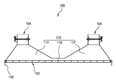
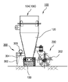
이들 도면에 도시되어 있는 바와 같이, 본 고안에 따른 노면 석션 장치는 도로의 청소 차량에 설치되어 흙, 먼지나 이물질을 흡입할 수 있게 한 것으로, 석션유닛(100)과 지지유닛(200) 및 비산방지유닛(300)을 포함하여 구성되는 것이 바람직하다. As shown in these figures, the road surface suction apparatus according to the present invention is installed in a cleaning vehicle on the road so as to suck soil, dust or foreign matter. The
상기 석션유닛(100)은 도로의 먼지나 이물질을 흡입할 수 있도록 차량의 하부 내측에 배치되도록 설치된다. 즉, 차량의 좌우 양측에 위치하는 브러시의 후방에 배치되도록 석션유닛(100)이 설치된다. The
이러한 석션유닛(100)은 차량의 폭에 대응하는 폭으로 이루어진 하나의 흡입구(102)가 하단에 구비되고, 상기 흡입구(102)의 상부에 좌우 양측으로 좌측연결구(104)와 우측연결구(106)가 각각 배치되도록 형성되어 호스가 각각 연결된다. The
이와 같이 하나의 흡입구(102)가 하단에 구비되고, 상부에 좌측연결구(104)와 우측연결구(106)가 일체형으로 구비될 수 있도록 상기 석션부재(100)는 전후면판재(110) 및 좌우면판재(120)로 이루어지는 것이 바람직하다. The
상기 전후면판재(110)는 석션유닛(100)의 전면과 후면을 형성하는 것으로, 상부가 좁고 하부가 넓은 상광하협의 부채꼴 형태로 구성되는 좌측부(112)와 우측부(114)가 서로 대칭으로 형성되고, 좌측부(112)와 우측부(114)를 연결하도록 좌측부(112)와 우측부(114)의 사이에 연결부(116)가 일체로 형성되는 하나의 판재로 형성된다. The front and
또한, 상기 좌우면판재(120)는 전후면판재(110)에 연결되어 상기 석션유닛(100)의 좌측과 우측을 형성하는 것으로, 역 사다리꼴 형상으로 형성된다. The left and right
이때, 상기 좌측연결구(104)와 우측연결구(106)가 각각 외측으로 위치되도록 상기 전후면판재(110)에 구비되는 좌측부(112)와 우측부(114)에 의해 형성되는 외측에 위치하는 경사면이 내측에 위치하는 경사면보다 급경사면을 이루게 형성되는 것이 바람직하다. At this time, the outer side inclined surface formed by the
또한, 상기 전후면판재(110)와 좌우면판재(120)의 하단에는 고무 재질로 이루어지는 블레이드(130)가 각각 하단으로 돌출되도록 설치되는 것이 바람직하다. In addition, it is preferable that a
따라서, 본 고안은 상기 석션유닛(100)에 구비되는 하단의 흡입구(102)가 하나로 구비됨에 의해 넓은 면적에서 흡입이 이루어지므로 흡입 효율을 향상시킬 수 있다. Accordingly, in the present invention, since the
도시된 바와 같이, 본 고안에 따른 노면 석션 장치에 구비되는 지지유닛(200)은 상기 석션유닛(100)의 뒤쪽에 설치되어 차량의 이동에 따라 구름운동을 하면서 석션유닛(100)을 지지하는 지지롤러(202)로 이루어지는 것이 바람직하다. As shown in the drawing, the
이러한 지지롤러(202)는 차량의 이동에 따라 제자리 회전됨과 아울러 선회 가능하도록 설치되는 것이 바람직하다. It is preferable that the
도시된 바와 같이, 본 고안에 따른 노면 석션 장치에 구비되는 비산방지유닛(300)은 상기 지지유닛(200)의 반대측에 위치하도록 상기 석션유닛(100)의 앞쪽에 설치되어 먼지나 이물질의 비산을 방지하는 역할을 한다. As shown in the drawing, the
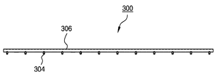
이러한 비산방지유닛(300)은 상기 석션유닛(100)의 전방으로 소정 간격을 갖도록 이격 설치되되, 지면으로부터 하단면이 소정 간격을 이루게 설치되는 비산방지판체(302)가 구비된다. The
또한, 상기 비산방지판체(302)와 석션유닛(100)의 사이에서 물을 분사할 수 있도록 복수 개의 물 분사노즐(304)이 상기 비산방지판체(302)와 석션유닛(100)의 사이에 설치되고, 상기 물 분사노즐(304)에 물을 공급할 수 있도록 물 공급관(306)이 설치되며, 이러한 물 공급관(306)에 상기 물 분사노즐(304)이 일정 간격을 이루게 설치되는 것이 바람직하다. A plurality of
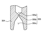
이때, 상기 물 분사노즐(304)은 물이 분사되도록 하는 분사공(305)이 형성되는 것이 바람직하다. At this time, the
이러한 분사공(305)의 사이즈는 직경 10-30mm 내의 범위를 가질 수 있다. 물론, 이의 수치에 본 고안의 권리범위가 제한될 수 없다. The size of the
상기 분사공(305)의 일 예로써, 첨부도면 도 7에 나타낸 바와 같이 축경홀(305a), 오리피스 연장홀(305b), 그리고 확경홀(305c)의 구조로 가공될 수 있다. As an example of the
상기 축경홀(305a)은 물이 분사되는 방향을 따라 점진적으로 직경이 감소되는 부분이다. 이러한 축경홀(305a)은 물이 분사공(305)으로 최초 유입되면서 생길 수 있는 와류(vortex)를 방지하도록 하여 균일하고 안정되게 분사할 수 있게 한다. The
또한, 상기 오리피스 연장홀(305b)은 축경홀(305a)에 연통되며, 축경홀(305a)의 최소 직경 부분이 연장되어 형성되는 부분이다. 이러한 오리피스 연장홀(305b)의 형상을 조절함으로써, 분사되는 물의 유속을 조절할 수 있다. The
그리고 상기 확경홀(305c)은 오리피스 연장홀(305b)에 연통되며, 물이 분사되는 방향을 따라 점진적으로 직경이 증가되는 부분이다. 이러한 확경홀(305c)은 물이 균일하고 안정되게 퍼지면서 분사되도록 하는 역할을 한다.The
이와 같이 분사공(305)을 단순 구멍이 아닌 축경홀(305a), 오리피스 연장홀(305b), 그리고 확경홀(305c)의 구조로 가공한 구조가 적용되어 물의 효율적인 분사가 이루어지게 할 수 있다. As described above, the structure in which the
따라서, 본 고안은 상기 물 분사노즐(304)을 통해 분사되는 물이 상기 비산방지판체(302)에 의해 전방으로 확산되지 않고 상기 비산방지판체(302)와 석션유닛(100)의 사이에서만 분사되게 하여 흡입 효율을 향상시킬 수 있다. Therefore, in the present invention, the water sprayed through the
이상에서와 같은 기술적 구성에 의해 본 고안의 기술적 과제가 달성되는 것이며, 비록 한정된 실시예와 도면에 의해 설명되었으나 여기에 한정되지 않고 본 고안이 속하는 기술분야에서 통상의 지식을 가진 자에 의해 극히 용이하게 본 고안의 기술사상과 아래에 기재될 실용신안등록청구범위의 균등범위 내에서 다양한 수정 및 변형이 가능한 것임은 물론이다.The technical object of the present invention is achieved by the technical structure as described above, and although it has been described by the limited embodiments and drawings, it is not limited thereto, and it is extremely easy It is obvious that various changes and modifications can be made within the scope of the technical idea of the present invention and the scope of claims of utility model registration described below.
100 - 석션유닛
102 - 흡입구
104 - 좌측연결구
106 - 우측연결구
200 - 지지유닛
202 - 지지롤러
300 - 비산방지유닛
302 - 비산방지판체
304 - 물 분사노즐
306 - 물 공급관100 - Suction unit 102 - Suction port
104 - Left connector 106 - Right connector
200 - support unit 202 - support roller
300 - Shatterproof unit 302 - Shatterproof sheet
304 - Water injection nozzle 306 - Water supply pipe
Claims (5)
상기 차량의 하부 내측에 배치되도록 설치되어 도로의 먼지나 이물질을 흡입할 수 있도록 상기 차량의 폭에 대응하는 폭으로 이루어진 하나의 흡입구가 하단에 구비되고, 상기 흡입구의 상부에 좌우 양측으로 배치되어 호스가 각각 연결되는 좌측연결구와 우측연결구가 구비된 석션유닛;
상기 석션유닛의 뒤쪽에 설치되어 차량의 이동에 따라 구름운동을 하면서 석션유닛을 지지하는 지지롤러로 이루어진 지지유닛; 및
상기 지지유닛의 반대측에 위치하도록 상기 석션유닛의 앞쪽에 설치되어 먼지나 이물질의 비산을 방지하는 비산방지유닛;을 포함하고,
상기 비산방지유닛은:
상기 석션유닛의 전방으로 소정 간격을 갖도록 이격 설치되되, 지면으로부터 하단면이 소정 간격을 이루게 설치되는 비산방지판체;
상기 비산방지판체와 석션유닛의 사이에서 물을 분사할 수 있도록 설치되는 복수 개의 물 분사노즐; 및
상기 물 분사노즐이 일정 간격을 이루게 설치되며, 상기 물 분사노즐에 물을 공급할 수 있는 물 공급관;으로 이루어지되,
상기 물 분사노즐을 통해 분사되는 물이 상기 비산방지판체에 의해 전방으로 확산되지 않고 상기 비산방지판체와 석션유닛의 사이에서만 분사되는 것을 특징으로 하는 노면 석션 장치.
BACKGROUND OF THE INVENTION 1. Field of the Invention [0001] The present invention relates to a road surface suction device installed in a cleaning vehicle on a road and capable of sucking dirt, dust,
A suction port provided at a lower end corresponding to the width of the vehicle so as to be able to suck dust and foreign matter from the road and disposed on the lower side of the suction port, A suction unit having a left connector and a right connector to which the left and right connectors are connected, respectively;
And a support roller provided at the rear of the suction unit and supporting the suction unit while rolling in accordance with movement of the vehicle. And
And a scattering prevention unit disposed at a front side of the suction unit to be positioned on the opposite side of the support unit to prevent scattering of dust and foreign matter,
The shatterproofing unit comprises:
A scattering prevention plate disposed at a predetermined distance in front of the suction unit and having a lower end surface spaced apart from the ground;
A plurality of water spray nozzles installed to spray water between the scatter preventive plate and the suction unit; And
And a water supply pipe installed at a predetermined interval between the water injection nozzles and capable of supplying water to the water injection nozzles,
Wherein the water sprayed through the water spray nozzle is sprayed only between the scattering prevention plate and the suction unit without being diffused forward by the scattering prevention plate.
상기 석션유닛은:
하단에 긴 직사각 형상으로 하나의 흡입구가 구비되고, 상부에 좌우 양측으로 각각 좌측연결구와 우측연결구가 일체형으로 구비되도록,
상기 석션유닛의 전면과 후면을 형성하는 상부가 좁고 하부가 넓은 상광하협의 부채꼴 형태로 구성되는 좌측부와 우측부가 서로 대칭으로 형성되며, 좌측부와 우측부를 연결하도록 좌측부와 우측부의 사이를 연결하는 연결부가 일체로 형성되는 하나의 판재로 형성된 전후면판재; 및
상기 전후면판재에 연결되어 상기 석션유닛의 좌측과 우측을 형성하는 역 사다리꼴 형상으로 형성된 좌우면판재;로 이루어지는 것을 특징으로 하는 노면 석션 장치.
The method according to claim 1,
The suction unit comprises:
And the left and right connectors are integrally formed on the left and right sides of the upper portion, respectively,
A left side portion and a right side portion which are formed in a fan shape having a narrow upper portion and a lower wide upper portion forming a front and a rear surface of the suction unit are formed symmetrically with each other and a connecting portion connecting the left portion and the right portion to connect the left portion and the right portion Front and rear plate members formed of a single plate member integrally formed; And
And a left and right side plate member connected to the front and back plate members and formed in an inverted trapezoidal shape forming left and right sides of the suction unit.
상기 석션유닛은:
상기 좌측연결구와 우측연결구가 각각 외측으로 위치되도록 상기 전후면판재에 구비되는 좌측부와 우측부에 의해 형성되는 외측에 위치하는 경사면이 내측에 위치하는 경사면보다 급경사면을 이루게 형성된 것을 특징으로 하는 노면 석션 장치.
3. The method of claim 2,
The suction unit comprises:
Wherein the front and rear right and left connecting members are formed on the front and rear plate members so that the left and right connecting members are located on the outer side, respectively, and the outer side slope formed by the right and left side portions has a steeply sloped surface, Device.
상기 석션유닛은:
상기 전후면판재 및 좌우면판재와의 하단으로 돌출되도록 고무 재질로 이루어지는 블레이드가 각각 설치된 것을 특징으로 하는 노면 석션 장치.
3. The method of claim 2,
The suction unit comprises:
And a blade made of a rubber material is provided so as to protrude from the lower ends of the front and rear plate members and the left and right plate members.
상기 물 분사노즐은:
물이 분사되도록 하는 분사공이 형성되되,
상기 분사공은:
물 공급관을 통해 공급되어 하부로 분사되는 방향을 따라 점진적으로 직경이 감소되는 축경홀과,
상기 축경홀에 연통되며, 상기 축경홀의 최소 직경 부분이 연장되어 형성되는 오리피스 연장홀과,
상기 오리피스 연장홀에 연통되며, 물이 분사되는 방향을 따라 점진적으로 직경이 증가되는 확경홀로 이루어진 것을 특징으로 하는 노면 석션 장치. The method according to claim 1,
The water injection nozzle comprises:
A spray hole for spraying water is formed,
The spray holes are:
An axial hole provided through the water supply pipe and gradually decreasing in diameter along a direction of spraying downward,
An orifice extension hole communicating with the shaft hole and formed by extending a minimum diameter portion of the shaft hole,
And an enlarged diameter hole communicating with the orifice extension hole and having a diameter gradually increased along a direction in which water is sprayed.
Priority Applications (1)
| Application Number | Priority Date | Filing Date | Title |
|---|---|---|---|
| KR2020170002333U KR20180003262U (en) | 2017-05-12 | 2017-05-12 | Road surface suction device |
Applications Claiming Priority (1)
| Application Number | Priority Date | Filing Date | Title |
|---|---|---|---|
| KR2020170002333U KR20180003262U (en) | 2017-05-12 | 2017-05-12 | Road surface suction device |
Publications (1)
| Publication Number | Publication Date |
|---|---|
| KR20180003262U true KR20180003262U (en) | 2018-11-21 |
Family
ID=64558053
Family Applications (1)
| Application Number | Title | Priority Date | Filing Date |
|---|---|---|---|
| KR2020170002333U KR20180003262U (en) | 2017-05-12 | 2017-05-12 | Road surface suction device |
Country Status (1)
| Country | Link |
|---|---|
| KR (1) | KR20180003262U (en) |
Cited By (1)
| Publication number | Priority date | Publication date | Assignee | Title |
|---|---|---|---|---|
| CN110280086A (en) * | 2019-06-27 | 2019-09-27 | 余艳 | A kind of multi-angle spray system for architectural environment |
Citations (1)
| Publication number | Priority date | Publication date | Assignee | Title |
|---|---|---|---|---|
| KR100936209B1 (en) | 2009-04-08 | 2010-01-11 | 김종순 | Road sweeper having a brushig unit |
-
2017
- 2017-05-12 KR KR2020170002333U patent/KR20180003262U/en not_active IP Right Cessation
Patent Citations (1)
| Publication number | Priority date | Publication date | Assignee | Title |
|---|---|---|---|---|
| KR100936209B1 (en) | 2009-04-08 | 2010-01-11 | 김종순 | Road sweeper having a brushig unit |
Cited By (1)
| Publication number | Priority date | Publication date | Assignee | Title |
|---|---|---|---|---|
| CN110280086A (en) * | 2019-06-27 | 2019-09-27 | 余艳 | A kind of multi-angle spray system for architectural environment |
Similar Documents
| Publication | Publication Date | Title |
|---|---|---|
| USRE39623E1 (en) | Sprayless surface cleaner | |
| KR101718125B1 (en) | Cleaning apparatus which can clean pedestrian road for road sweeping vehicle | |
| KR101584794B1 (en) | Cleanning apparatus for dry type road sweeping vehicle | |
| RU2008141963A (en) | SPRAY HOSE WITH DISPOSABLE SPRAY | |
| CN105534422A (en) | Washing recovery device of cleaning machine | |
| CN105615762A (en) | Manufacturing method of automatic cleaning device | |
| US7290307B1 (en) | Implement for removing pavement cleaner | |
| KR20180003262U (en) | Road surface suction device | |
| US8959705B2 (en) | Robot for cleaning smooth surfaces | |
| KR101664332B1 (en) | nozzle turning apparatus for wter sprinkling of vehicles | |
| CN101137317A (en) | Hard and soft floor cleaning tool and machine | |
| KR102536138B1 (en) | Water-soluble composition coating device for eco-friendly paper production | |
| US20150096133A1 (en) | Floor scrubber and scrubber head | |
| EP2463441B1 (en) | Dust control system | |
| CN210810819U (en) | Floor nozzle for a wet surface cleaning device | |
| US20220408993A1 (en) | Air agitator nozzle system | |
| KR100619452B1 (en) | Rear brushing apparatus for watering vehicle | |
| CN105520682A (en) | Cleaning device of automatic cleaning machinery | |
| CN213524978U (en) | Surface cleaning apparatus | |
| CN105499176A (en) | Handheld vehicle cleaning equipment | |
| KR100635641B1 (en) | Robot vacuum cleaner having water spray | |
| CN217039998U (en) | Ground cleaning machine capable of spraying water externally | |
| KR100466220B1 (en) | Apparatus for preventing floating dusts from being scattered in road scavenger's cart | |
| KR200416105Y1 (en) | rear brushing apparatus for watering vehicle | |
| KR20180126404A (en) | Squeegee for a floor cleaning machine |
Legal Events
| Date | Code | Title | Description |
|---|---|---|---|
| A201 | Request for examination | ||
| A302 | Request for accelerated examination | ||
| E902 | Notification of reason for refusal | ||
| AMND | Amendment | ||
| E601 | Decision to refuse application | ||
| AMND | Amendment | ||
| X601 | Decision of rejection after re-examination | ||
| J201 | Request for trial against refusal decision |
Free format text: TRIAL NUMBER: 2018101000908; TRIAL AGAINST DECISION OF REJECTION FOR APPEAL AGAINST DECISION TO DECLINE REFUSAL |
|
| J301 | Trial decision |
Free format text: TRIAL NUMBER: 2018101000908; TRIAL DECISION FOR APPEAL AGAINST DECISION TO DECLINE REFUSAL REQUESTED 20180228 Effective date: 20190723 |