KR20170122341A - Flexible Brake pad - Google Patents
Flexible Brake pad Download PDFInfo
- Publication number
- KR20170122341A KR20170122341A KR1020160050959A KR20160050959A KR20170122341A KR 20170122341 A KR20170122341 A KR 20170122341A KR 1020160050959 A KR1020160050959 A KR 1020160050959A KR 20160050959 A KR20160050959 A KR 20160050959A KR 20170122341 A KR20170122341 A KR 20170122341A
- Authority
- KR
- South Korea
- Prior art keywords
- plate
- elastic member
- friction
- center hole
- elastic
- Prior art date
Links
Images


Classifications
-
- F—MECHANICAL ENGINEERING; LIGHTING; HEATING; WEAPONS; BLASTING
- F16—ENGINEERING ELEMENTS AND UNITS; GENERAL MEASURES FOR PRODUCING AND MAINTAINING EFFECTIVE FUNCTIONING OF MACHINES OR INSTALLATIONS; THERMAL INSULATION IN GENERAL
- F16D—COUPLINGS FOR TRANSMITTING ROTATION; CLUTCHES; BRAKES
- F16D65/00—Parts or details
- F16D65/02—Braking members; Mounting thereof
- F16D65/04—Bands, shoes or pads; Pivots or supporting members therefor
- F16D65/092—Bands, shoes or pads; Pivots or supporting members therefor for axially-engaging brakes, e.g. disc brakes
- F16D65/095—Pivots or supporting members therefor
- F16D65/097—Resilient means interposed between pads and supporting members or other brake parts
-
- B—PERFORMING OPERATIONS; TRANSPORTING
- B61—RAILWAYS
- B61H—BRAKES OR OTHER RETARDING DEVICES SPECIALLY ADAPTED FOR RAIL VEHICLES; ARRANGEMENT OR DISPOSITION THEREOF IN RAIL VEHICLES
- B61H5/00—Applications or arrangements of brakes with substantially radial braking surfaces pressed together in axial direction, e.g. disc brakes
-
- F—MECHANICAL ENGINEERING; LIGHTING; HEATING; WEAPONS; BLASTING
- F16—ENGINEERING ELEMENTS AND UNITS; GENERAL MEASURES FOR PRODUCING AND MAINTAINING EFFECTIVE FUNCTIONING OF MACHINES OR INSTALLATIONS; THERMAL INSULATION IN GENERAL
- F16D—COUPLINGS FOR TRANSMITTING ROTATION; CLUTCHES; BRAKES
- F16D65/00—Parts or details
- F16D65/02—Braking members; Mounting thereof
- F16D65/04—Bands, shoes or pads; Pivots or supporting members therefor
- F16D65/092—Bands, shoes or pads; Pivots or supporting members therefor for axially-engaging brakes, e.g. disc brakes
Abstract
Description
본 발명은 소결 마찰 부재를 구비하여 고속철도용으로 사용되는 탄성 브레이크 패드에 관한 것이다.The present invention relates to an elastic brake pad having a sintered friction member and used for a high-speed railway.
일반적으로 운동 에너지가 발생하는 운송 수단, 예를 들어, 차량 등에 사용되는 브레이크 조립체를 구성하는 브레이크 패드는 소정 형상의 마찰 부재와 마찰 부재를 지지하는 지지 부재, 지지 부재가 고정된 백플레이트 및 백플레이트 하면에 결합되어 브레이크 시스템에 장착되는 도브 테일을 포함한다. 차량의 구동 샤프트에 연동되어 회전하는 브레이크 디스크에 브레이크 패드의 마찰 부재가 직접 접촉함으로써 브레이크 디스크와 마찰 부재 사이에 마찰력이 발생하며, 마찰력으로 인하여 철도 차량이 제동된다. BACKGROUND ART A brake pad constituting a brake assembly used in a transportation means such as a vehicle in which kinetic energy is generated generally includes a friction member having a predetermined shape and a support member for supporting the friction member, And a dove tail coupled to the lower surface and mounted to the brake system. A frictional force is generated between the brake disc and the friction member due to the friction member of the brake pad directly contacting the brake disc rotating in conjunction with the drive shaft of the vehicle, and the railway vehicle is braked due to the frictional force.
상기 브레이크 패드는 일반적으로 구조상의 특징에 따라 두 가지로 분류될 수 있다. 상기 브레이크 패드는 마찰 부재가 백플레이트에 고정되어 유동되지 않는 고정 타입(Rigid Type)과 마찰 부재가 백플레이트에 고정되지만 마찰 과정에서 압부력을 받았을 때 유동되어 플렉서블한 특성을 갖는 플렉서블 타입(Flexible Type)으로 분류 할 수 있다. The brake pads can be generally classified into two types according to their structural characteristics. The brake pad is a rigid type in which the friction member is fixed to the back plate and does not flow, and a flexible type in which the friction member is fixed to the back plate but is flexible when the pressure is applied in the friction process. ).
상기 고정 타입의 브레이크 패드는 마찰 과정에서 유압 또는 공압에 의해 압부력이 가해지면 마찰 부재가 브레이크 디스크 표면에 직접적으로 압력을 전달하여 제동하는 타입으로 마찰 부재가 브레이크 디스크에 대하여 유동하지 않으며 브레이크 디스크 형상이나 인가되는 압부력의 차이를 반영할 수 없는 단점이 있다. 또한, 상기 마찰 부재에 동일한 압부력이 가해지므로, 마찰 과정에서 각각의 마찰 부재에서 편마모가 발생할 확률이 증가하여 마찰 부재의 균일한 마모가 진행되지 않는 단점이 있다. 또한, 상기 고정 타입의 브레이크 패드는 마찰 부재가 브레이크 디스크의 표면에 접촉될 때, 마찰 부재의 전체 면적이 브레이크 디스크와 접촉되지 않으므로 제동 면적이 감소하고 국부적으로 높은 마찰열이 발생되는 단점이 있다. 또한, 상기 고정 타입의 브레이크 패드는 제동면 전체에 균일한 압력이 전달되지 못하기 때문에 브레이크 디스크에 가해지는 열적 충격을 증가시키고, 브레이크 디스크의 수명을 단축시키고 브레이크 디스크의 파손으로 연결될 수 있는 원인이 되기도 한다. The fixed type brake pad is a type in which when the pressing force is applied by hydraulic pressure or air pressure in the course of friction, the friction member directly brakes by transmitting pressure to the surface of the brake disk, so that the friction member does not flow to the brake disk, And the difference in applied pressure force can not be reflected. In addition, since the same pressing force is applied to the friction member, the probability of occurrence of uneven wear in each friction member during the friction process increases, and uniform wear of the friction member does not proceed. In addition, when the friction member is brought into contact with the surface of the brake disc, the fixed-type brake pad has a disadvantage in that the entire area of the friction member is not in contact with the brake disc, so that the braking area is reduced and locally high frictional heat is generated. In addition, since the fixed type brake pad can not transmit a uniform pressure to the entire braking surface, thermal shock applied to the brake disk increases, shortening the service life of the brake disk and causing breakage of the brake disk. It is.
따라서, 상기 고정 타입의 브레이크 패드의 단점을 보완하기 위하여, 현재 고속철도용 브레이크 패드는 플렉서블 타입으로 개발되어 사용되고 있다. 일반적으로 상기 플렉서블 타입의 브레이크 패드는 마찰 부재를 지지하는 지지 부재와 백플레이트 사이에 스프링 기능을 하는 제 1 탄성 부재를 포함하여 형성된다. 상기 제 1 탄성 부재는 마찰 부재와 지지 부재를 지지하면서, 마찰 과정에서 변형되어 마찰 부재가 유동되도록 하여 브레이크 디스크 표면과 전체적으로 균일하게 접촉되도록 형성되고 있다. 그러나 상기 플렉서블 타입의 브레이크 패드는 스프링 기능을 하는 제 1 탄성 부재의 구조가 복잡하여 제조하는데 어려움이 많으며, 복잡한 구조로 인하여 마찰 성능 및 내구성이 저하되는 문제가 있다.Therefore, in order to compensate for the disadvantages of the fixed type brake pads, brake pads for high-speed railways have been developed and used in a flexible type. Generally, the flexible type brake pad is formed by including a first elastic member that functions as a spring between a support member for supporting the friction member and the back plate. The first elastic member is formed to support the friction member and the support member while being deformed in the friction process so as to allow the friction member to flow, thereby making uniform contact with the surface of the brake disc as a whole. However, the brake pad of the flexible type has a complicated structure due to the complicated structure of the first elastic member having a spring function, and has a problem that the frictional performance and the durability are deteriorated due to the complicated structure.
본 발명은 제 1 탄성 부재와 제 2 탄성 부재를 이용하여 복수 개의 마찰 부재의 표면이 전체적으로 균일하게 브레이크 디스크의 마찰 표면에 접촉될 수 있도록 하는 브레이크 패드를 제공하는데 그 목적이 있다.An object of the present invention is to provide a brake pad that allows the surfaces of a plurality of friction members to be uniformly contacted to the friction surface of the brake disk by using the first elastic member and the second elastic member.
본 발명의 탄성 브레이크 패드는 적어도 하나의 마찰 부재와, 상기 마찰 부재에 대응되는 수로 형성되며, 상기 마찰 부재의 하면에 접합되어 결합되는 지지 부재와, 상기 지지 부재의 하면에 결합되는 상부판과 상기 상부판의 양측단에서 하부 방향으로 호 형상으로 절곡되어 형성되는 연결판 및 상기 연결판의 하단에 상기 상부판의 내측 방향으로 연장되는 판상으로 형성되는 하부판을 구비하는 제 1 탄성 부재와, 콘 형상이며, 상기 제 1 탄성 부재의 내부에 위치하는 상부판과 상기 하부판 사이에 위치하는 제 2 탄성 부재 및 상기 제 1 탄성 부재의 하부판 하면이 결합되는 백플레이트를 포함하는 것을 특징으로 한다.The elastic brake pad of the present invention comprises at least one friction member, a support member formed in a number corresponding to the friction member and joined to the lower surface of the friction member to be coupled to each other, an upper plate coupled to a lower surface of the support member, A first elastic member having a connecting plate formed by bending the upper plate in a downward arc at both side ends thereof and a lower plate formed in a plate shape extending in the inner direction of the upper plate at a lower end of the connecting plate, And a second elastic member positioned between the upper plate and the lower plate positioned in the first elastic member and a back plate coupled to the lower surface of the first elastic member.
또한, 상기 탄성 브레이크 패드는 상기 백플레이트의 하부에 결합되는 도브 테일을 더 포함하여 형성될 수 있다.Further, the elastic brake pad may further include a dove tail coupled to a lower portion of the back plate.
또한, 상기 지지 부재는 돌기 또는 홈 형상으로 형성되는 하부 결합부를 포함하며, 상기 제 1 탄성 부재의 상부판은 상기 하부 결합부에 대응되는 위치에 형성되는 홈 또는 돌기 형상의 상부 결합부를 더 포함하며, 상기 하부 결합부와 상부 결합부는 서로 결합되어 상기 지지 부재가 마찰 과정에서 회전하는 것을 방지하도록 형성될 수 있다.The support member may include a lower engaging portion formed in a protrusion or a groove shape, and the upper plate of the first elastic member may further include a groove or a protrusion-shaped upper engaging portion formed at a position corresponding to the lower engaging portion, The lower engaging portion and the upper engaging portion may be coupled to each other to prevent the support member from rotating in the course of friction.
또한, 상기 마찰 부재는 상하로 관통되는 제 1 중앙홀을 구비하며, 상기 지지 부재는 상하로 관통되며 상기 제 1 중앙홀에 대응되는 위치에 형성되는 제 2 중앙홀을 구비하며, 상기 제 1 탄성 부재는 상기 상부판에 상기 제 1 중앙홀에 대응되는 위치에 형성되는 제 3 중앙홀을 구비하며, 상기 백플레이트는 제 1 중앙홀에 대응되는 위치에 형성되는 제 5 중앙홀을 구비하며, 상기 제 2 탄성 부재는 제 4 중앙홀을 구비하며, 상기 제 4 중앙홀이 상기 제 1 중앙홀에 대응되는 위치에 위치하도록 상기 상부판의 하면과 상기 백플레이트의 상면 사이에 위치할 수 있다. 이때, 상기 하부판은 내측단이 서로 이격되는 두 개의 판상으로 형성되며, 상기 제 2 탄성 부재는 상기 하부판의 내측단 사이에 위치하며, 상기 제 1 탄성 부재의 하부판 사이의 거리보다 작은 외경을 갖도록 형성될 수 있다.The friction member has a first center hole penetrating vertically, the support member having a second center hole penetrating vertically and formed at a position corresponding to the first center hole, Wherein the member has a third central hole formed in the upper plate at a position corresponding to the first center hole and the back plate has a fifth central hole formed at a position corresponding to the first center hole, The second elastic member may include a fourth center hole and may be positioned between the lower surface of the upper plate and the upper surface of the back plate such that the fourth center hole is located at a position corresponding to the first center hole. The second elastic member is disposed between the inner ends of the lower plate and is formed to have an outer diameter smaller than a distance between the lower plates of the first elastic member. .
또한, 상기 제 2 탄성 부재는 상기 백플레이트의 상면과 상기 상부판의 하면 사이의 높이에 대응되는 높이를 가지며, 상기 제 4 중앙홀은 상기 상부판의 제 3 중앙홀의 내경보다 큰 내경을 가지며, 상기 백플레이트의 제 5 중앙홀의 내경보다 큰 내경을 가지도록 형성될 수 있다.The second elastic member may have a height corresponding to a height between an upper surface of the back plate and a lower surface of the upper plate, and the fourth center hole may have an inner diameter larger than an inner diameter of the third center hole of the upper plate, And may have an inner diameter larger than an inner diameter of the fifth central hole of the back plate.
본 발명에 따른 탄성 브레이크 패드는 제 1 탄성 부재와 제 2 탄성 부재를 사용하여 마찰 부재와 지지 부재를 지지하면서 마찰 과정에서 마찰 부재가 브레이크 디스크의 마찰 표면에 대하여 유동되도록 하는 효과가 있다.The elastic brake pad according to the present invention has the effect of supporting the friction member and the support member by using the first elastic member and the second elastic member and causing the friction member to flow against the friction surface of the brake disk during the friction process.
또한, 본 발명에 따른 탄성 브레이크 패드는 마찰 부재를 지지하는 지지 부재와 백플레이트 사이에 제 1 탄성 부재와 제 2 탄성 부재가 장착되어 마찰 부재의 표면이 전체적으로 균일하게 브레이크 디스크의 마찰 표면에 접촉되도록 하는 효과가 있다.The elastic brake pad according to the present invention is characterized in that the first elastic member and the second elastic member are mounted between the support member for supporting the friction member and the back plate so that the surface of the friction member is uniformly contacted to the friction surface of the brake disc as a whole .
또한, 본 발명에 따른 탄성 브레이크 패드는 마찰 부재가 브레이크 디스크의 마찰 표면에 균일하게 접촉되므로 브레이크 디스크가 제동 마찰열에 의하여 부분적으로 과열되어 열충격을 받는 것이 감소되어 브레이크 디스크의 손상이 방지되고 수명이 연장되는 효과가 있다. In addition, the elastic brake pad according to the present invention can prevent the brake disc from being damaged and the life of the brake disc is prolonged because the friction member uniformly contacts the friction surface of the brake disc, so that the brake disc is partially overheated by the brake friction heat, .
또한, 본 발명에 따른 탄성 브레이크 패드는 유동을 갖는 각각의 제 1 탄성 부재에 의하여 마찰 부재와 지지 부재가 지지되므로 마찰 과정에서 발생되는 마찰 열의 배출이 용이하며, 제동 소음도 감소되는 효과가 있다.In addition, since the friction member and the support member are supported by the respective first elastic members having the flow, the elastic brake pad according to the present invention has an effect of facilitating the discharge of the friction heat generated in the friction process and reducing the braking noise.
도 1은 본 발명의 일 실시예에 따른 탄성 브레이크 패드의 평면도이다.
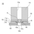
도 2는 도 1의 A-A를 따라 절취한 상태의 수직 단면도이다.
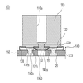
도 3은 도 1의 B-B를 따라 절취한 상태의 수직 단면도이다.
도 4는 도 1에 도시된 제 1 탄성 부재의 평면도이다.
도 5는 도 4의 C-C를 따라 절취한 상태의 수직 단면도이다.
도 6은 도 1에 도시된 제 2 탄성 부재의 평면도이다.
도 7은 도 1에 도시된 백플레이트의 평면도이다.
도 8은 백플레이트에 결합되는 도브 테일의 평면도이다.1 is a plan view of an elastic brake pad according to an embodiment of the present invention.
2 is a vertical cross-sectional view taken along line AA of FIG.
3 is a vertical cross-sectional view taken along line BB of FIG.
4 is a plan view of the first elastic member shown in Fig.
5 is a vertical cross-sectional view taken along the line CC of FIG.
6 is a plan view of the second elastic member shown in Fig.
7 is a plan view of the back plate shown in Fig.
8 is a plan view of a dove tail coupled to a back plate;
이하, 본 발명의 실시예에 따른 탄성 브레이크 패드를 첨부된 도면을 통하여 상세히 설명한다. Hereinafter, an elastic brake pad according to an embodiment of the present invention will be described in detail with reference to the accompanying drawings.
도 1은 본 발명의 일 실시예에 따른 탄성 브레이크 패드의 평면도이다. 도 2는 도 1의 A-A를 따라 절취한 상태의 수직 단면도이다. 도 3은 도 1의 B-B를 따라 절취한 상태의 수직 단면도이다. 도 4는 도 1에 도시된 제 1 탄성 부재의 평면도이다. 도 5는 도 4의 C-C를 따라 절취한 상태의 수직 단면도이다. 도 6은 도 1에 도시된 제 2 탄성 부재의 평면도이다. 도 7은 도 1에 도시된 백플레이트의 평면도이다. 도 8은 백플레이트에 결합되는 도브 테일의 평면도이다.1 is a plan view of an elastic brake pad according to an embodiment of the present invention. 2 is a vertical sectional view taken along the line A-A of FIG. 3 is a vertical cross-sectional view taken along the line B-B in Fig. 4 is a plan view of the first elastic member shown in Fig. 5 is a vertical cross-sectional view taken along the line C-C of FIG. 6 is a plan view of the second elastic member shown in Fig. 7 is a plan view of the back plate shown in Fig. 8 is a plan view of a dove tail coupled to a back plate;
본 발명의 일 실시예에 따른 탄성 브레이크 패드(100)는, 도 1 내지 도 8을 참조하면, 마찰 부재(110)와 지지 부재(120)와 제 1 탄성 부재(130)와 제 2 탄성 부재(140) 및 백플레이트(150)를 포함하여 형성된다. 또한, 상기 탄성 브레이크 패드(100)는 도브 테일(160)을 더 포함하여 형성될 수 있다.1 to 8, the
상기 탄성 브레이크 패드(100)는 지지 부재(120)를 지지하는 제 1 탄성 부재(130)와 제 2 탄성 부재(140)에 의하여 마찰 과정에서 마찰 부재(110)가 유동되면서 전체적으로 균일하게 브레이크 디스크(미도시)에 접촉된다. The
또한, 상기 탄성 브레이크 패드(100)는 제 1 탄성 부재(130)가 제 2 탄성 부재(140)에 의하여 지지되므로, 제 1 탄성 부재(130)가 마찰 부재(110)의 마찰 과정에서 발생되어 전달되는 열에 의하여 가열되더라도 주저앉는 것이 방지되며 탄성력을 유지한다.Since the first
또한, 상기 탄성 브레이크 패드(100)는 좌우 대칭인 두 개의 탄성 브레이크 패드가 한 쌍을 이루며 하나의 도브 테일(160)에 결합된다. 따라서, 상기 탄성 브레이크 패드(100)는 백플레이트(150)가 두 개로 분리되어 도브 테일(160)에 결합되므로 마찰 부재(110)의 마찰 과정에서 발생되어 전달되는 열에 의한 변형이 감소된다.In addition, the
이하의 설명에서, 상측 또는 상면은 도 1을 기준으로 +z 축을 향하는 방향 또는 면을 의미하며, 하측 또는 하면은 -z축을 향하는 방향 또는 면을 의미한다. 또한, 수평 방향은 +z축에 수직이고 +x축 및 y축에 평행인 방향을 의미한다. 또한, 일측은 -x 축 방향, 타측은 +x축 방향을 의미한다. 또한, 전측은 +y축 방향, 후측은 -y축 방향을 의미한다.In the following description, the upper side or the upper side refers to a direction or a face toward the + z axis with reference to Fig. 1, and the lower side or lower side means a direction or face toward the -z axis. In addition, the horizontal direction means a direction perpendicular to the + z-axis and parallel to the + x-axis and the y-axis. Further, one side indicates the -x axis direction and the other side indicates the + x axis direction. Further, the front means the + y axis direction and the rear side means the -y axis direction.
상기 마찰 부재(110)는 수평 단면이 대략 사각 형상이며, 소정 높이를 갖는 기둥 형상으로 형성된다. 다만, 여기서 상기 마찰부재(110)의 형상을 한정하는 것은 아니며, 원 기둥, 삼각 기둥 또는 육각 기둥과 같은 형상으로 형성될 수 있다. 상기 마찰 부재(110)는 브레이크 시스템의 사양과 탄성 브레이크 패드(100)의 교체 주기에 따라 소정 형상과 높이로 형성될 수 있다. The
상기 마찰 부재(110)는 제 1 중앙홀(110a)을 포함하여 형성된다. 상기 제 1 중앙홀(110a)은 마찰 부재(110)의 수평면을 기준으로 중앙 영역에 형성되며, 바람직하게는 중심에 형성된다. 상기 제 1 중앙홀(110a)은 마찰 부재(110)의 상면에서 하면으로 관통되는 소정 직경을 갖는 홀로 형성된다. 상기 제 1 중앙홀(110a)은 지지 부재(120)를 제 1 탄성 부재(130)에 고정하기 위한 중앙 리벳(10)이 삽입되는 통로를 제공하게 된다. 따라서, 상기 제 1 중앙홀(110a)은 바람직하게는 중앙 리벳(10)의 머리 부분의 직경보다 큰 직경을 가지도록 형성된다. 또한, 상기 제 1 중앙홀(110a)은 마찰 부재(110)의 마찰 과정에서 발생되는 입자들을 수용하여 마찰 부재(110)와 브레이크 디스크의 마찰이 원활하게 이루어지도록 한다. 또한, 상기 제 1 중앙홀(110a)은 마찰 과정에서 발생되는 열이 발산되는 통로를 제공한다.The
상기 마찰 부재(110)는 하면이 소결 과정에서 지지 부재(120)의 상면과 결합된다. 상기 마찰 부재(110)는 온도가 가해지는 연속 소결 방식 또는 온도와 압력이 동시에 가해지는 가압 소결 방식에 의하여 제조될 수 있다. 상기 마찰 부재(110)는 소결 과정에서 지지 부재(120)와 결합되어 백플레이트(150)에 고정된다. 상기 마찰 부재(110)는 소결 과정에서 브레이징 접합 또는 동시 가압 소결 접합에 의하여 지지 부재(120)와 결합된다. The lower surface of the
상기 마찰 부재(110)는 금속 재료로 형성되는 기지부와 기지부에 분산되며 세라믹 또는 흑연과 같은 비금속을 포함하는 마찰 조정제를 포함하여 형성된다. 상기 마찰 부재(110)의 기지부는 철을 주성분으로 하는 철계 또는 구리를 주성분으로 하는 동계로 형성될 수 있다. 또한, 상기 기지부는 철계로 형성되는 경우에 철(Fe)외에 망간(Mn), 몰리브덴(Mo)과 같은 성분을 포함하여 형성될 수 있다. 또한 상기 기지부는 동계로 형성되는 경우에 구리(Cu)외에 주석(Sn), 니켈(Ni), 철(Fe), 몰리브덴(Mo)과 같은 성분을 포함하여 형성될 수 있다. 따라서, 상기 기지부는 탄성 브레이크 패드(100)에 요구되는 마찰특성, 내열성, 내구성 등 제반 특성을 고려하여 선택적으로 금속 재료가 사용될 수 있으며, 여기서 금속 재료의 성분을 한정하는 것은 아니다. 상기 마찰 조정제는 알루미나, 실리콘 산화물과 같은 세라믹, 흑연과 같은 재료를 포함하며, 탄성 브레이크 패드(100)에 요구되는 마찰특성, 내열성, 내구성 등 제반 특성을 고려하여 다양한 재료가 선택적으로 사용될 수 있다.The
상기 지지 부재(120)는 제 2 중앙홀(120a)과 하부 결합부(120b)를 포함하여 형성된다. 상기 지지 부재(120)는 마찰 부재(110)의 평면 형상 또는 하면에 대응되는 형상을 가지는 판상으로 형성된다. 상기 지지 부재(120)는 마찰 부재(110)의 수에 대응되는 수로 형성되며, 상면에 결합되는 마찰 부재(110)를 지지하게 된다. 또한, 상기 지지 부재(120)는 하면이 제 1 탄성 부재(130)에 결합된다. The
상기 제 2 중앙홀(120a)은 지지 부재(120)의 상면에서 하면으로 관통되는 홀 형상으로 형성되며, 지지 부재(120)의 상면을 기준으로 중앙에 형성된다. 상기 제 2 중앙홀(120a)은 지지 부재(120)가 마찰 부재(110)와 결합될 때 제 1 중앙홀(110a)에 대응되는 위치에 형성된다. 상기 제 2 중앙홀(120a)은 지지 부재(120)와 제 1 탄성 부재(130)을 결합시키기 위한 중앙 리벳(10)이 삽입된다. 따라서, 상기 제 2 중앙홀(120a)은 삽입되는 중앙 리벳(10)의 외경에 대응되는 내경을 가지도록 형성된다. The
상기 하부 결합부(120b)는, 도 3에 도시된 바와 같이, 지지 부재(120)의 하면에서 하부 방향으로 돌출되는 소정 높이의 돌기 형상으로 형성된다. 또한, 상기 하부 결합부(120b)는 구체적으로 도시하지 않았지만 하면에서 상부로 연장되는 소정 깊이의 홈 형상으로 형성될 수 있다. 즉, 상기 하부 결합부(120b)는 하부 지지 돌기 또는 하부 지지 홈으로 형성될 수 있다. 상기 하부 결합부(120b)가 돌기 형상으로 형성되는 경우에 하면에서 하부 방향으로 돌출되는 돔 형상으로 형성될 수 있다. 또한, 상기 하부 결합부(120b)는 수평 단면 형상이 원형 또는 사각형인 돌기 또는 홈 형상으로 형성될 수 있다. 상기 하부 결합부(120b)는 지지 부재(120)의 평면 형상에 따라 복수 개로 형성된다. 예를 들면, 상기 하부 결합부(120b)는 지지 부재(120)가 사각 형상으로 형성되는 경우에 각 모서리에 형성되어 4개로 형성된다. 또한, 상기 지지 부재(120)가 원형 또는 육각 형상으로 형성되는 경우에 제 2 중앙홀(120a)을 중심으로 원주 방향을 따라 3 개 이상으로 형성될 수 있다. 따라서, 상기 하부 결합부(120b)는 바람직하게는 적어도 3개로 형성된다. 상기 하부 결합부(120b)는 제 1 탄성 부재(130)와 결합되어 마찰 부재(110)와 지지 부재(120)가 마찰 과정에서 중앙 리벳(10)을 중심으로 회전하는 것을 방지한다.As shown in FIG. 3, the lower
상기 제 1 탄성 부재(130)는 상부판(131)과 연결판(133) 및 하부판(135)을 포함하여 형성된다. 상기 제 1 탄성 부재(130)는 하나의 판상이 절곡되어 상부판(131)과 연결판(133) 및 하부판(135)이 일체로 형성될 수 있다. 상기 제 1 탄성 부재(130)는 상부판(131)과 하부판(135)을 연결하는 연결판(133)에 의하여 스프링 역할을 한다. 또한, 상기 제 1 탄성 부재(130)는 상부판(131)이 지지 부재(120)의 하면에 결합되며, 마찰 부재(110) 및 지지 부재(120)를 지지한다. 또한, 상기 제 1 탄성 부재(130)는 하부판(135)이 백플레이트(150)에 결합된다. 상기 제 1 탄성 부재(130)는 스프링강, 스테인레스 스틸과 같은 적절한 금속 재질로 형성될 수 있다.The first
상기 제 1 탄성 부재(130)는 마찰 과정에서 상부판(131)이 연결판(133)의 스프링 역할에 의하여 수평 방향에 대하여 상하로 유동하면서 마찰 부재(110)가 유동되도록 한다. The first
상기 상부판(131)은 제 3 중앙홀(131a)과 상부 결합부(131b)를 포함하여 형성된다. 상기 상부판(131)은 지지 부재(120)의 평면 형상 또는 하면에 대응되는 형상을 가지는 판상으로 형성된다. 또한, 상기 상부판(131)은 지지 부재(120)보다 더 넓은 면적을 가지도록 형성될 수 있다. 즉, 상기 상부판(131)은 지지 부재(120)의 양측 또는 전후측보다 돌출되도록 형성될 수 있다. 상기 상부판(130)는 지지 부재(120)의 수에 대응되는 수로 형성되며, 상면에 결합되는 지지 부재(120)를 지지하게 된다.The
상기 제 3 중앙홀(131a)은 상부판(131)의 상면에서 하면으로 관통되는 홀 형상으로 형성되며, 상부판(131)의 상면을 기준으로 중앙에 형성된다. 이때, 상기 제 3 중앙홀(131a)은 마찰 부재(110)의 제 1 중앙홀(110a) 및 지지 부재(120)의 제 2 중앙홀(120a)와 동일 중심을 갖는 위치에 형성된다. 상기 제 3 중앙홀(131a)은 지지 부재(120)와 상부판(131)을 결합하기 위한 중앙 리벳(10)이 결합된다. 따라서, 상기 제 3 중앙홀(131a)은 삽입되는 중앙 리벳(10)의 외경에 대응되는 내경을 가지도록 형성된다. 상기 중앙 리벳(10)은 제 2 중앙홀(120a)과 제 3 중앙홀(131a)을 관통하여 삽입되며, 지지 부재(120)와 제 1 탄성 부재(130)의 상부판(131)을 결합시킨다.The
상기 상부 결합부(131b)는 하부 결합부(120b)에 대응되는 위치에 하부 결합부(120b)와 결합되는 반대 형상으로 형성된다. 예를 들면, 상기 하부 결합부(120b)가 돌기 형상으로 형성되는 경우에, 상부 결합부(131b)는 상부판(131)의 상면에서 하면으로 관통되는 홀 또는 홈 형상으로 형성된다. 또한, 상기 하부 결합부(120b)가 홈 형상으로 형성되는 경우에 상부판(131)의 상면에서 상부로 돌출되는 돌기 형상으로 형성된다. 상기 상부 결합부(131b)는 하부 결합부(120b)에 대응되는 수로 형성된다. 상기 상부 결합부(131b)는 하부 결합부(120b)와 결합되어 마찰 과정에서 지지 부재(120) 및 마찰 부재(110)가 회전하는 것을 방지한다. The
상기 연결판(133)은 상부판(131)의 양측단에서 하부 방향으로 절곡되어 형성되며, y축에 수직인 방향의 단면 형상이 호 형상 또는 이에 상응하는 형상을 이루도록 형성된다. 즉, 상기 연결판(133)은 두 개로 형성되며 각각의 상단이 상부판(131)의 양측단과 각각 연결되며, 하단이 하부판(135)의 양측단과 연결되도록 형성된다. 또한, 상기 연결판(133)은 호 형상외에도 육각 호 형상, 팔각 호 형상과 같이 육각형, 팔각형의 일부분에 의하여 이루어지는 호 형상에 상응하는 형상으로 형성될 수 있다. 상기 연결판(133)은 충분한 탄성력을 갖기 위하여 호의 각도가 180도 이상이 되도록 형성된다. 또한, 상기 연결판(133)은 충분한 탄성력을 갖기 위하여 호의 반지름이 연결판(133) 두께의 1 내지 3배가 되도록 형성될 수 있다. 상기 연결판(133)은 호 형상으로 형성되므로 상부판(131)이 마찰 과정에서 압부력을 받을 때 변형되면서 상부판(131)이 유동되도록 한다. 또한, 상기 연결판(133)은 마찰 과정에 종료되면 상부판(131)이 복원되도록 한다. The connecting
상기 하부판(135)은 제 3 하부홀(135a)을 포함하여 형성된다. 상기 하부판(135)은 연결판(133)의 하단에서 상부판(131)의 내측 방향으로 연장되는 판상으로 형성된다. 상기 하부판(135)은 바람직하게는 상부판(131)과 평행하도록 형성된다. 상기 하부판(135)은 전체적으로 상부판(131)에 대응되는 형상으로 형성된다. 다만, 상기 하부판(135)은 바람직하게는 2 개의 판으로 형성되며, 내측단이 서로 이격되도록 형성되어 중앙 리벳(10)의 하부 머리와 제 2 탄성 부재(140)가 수용되는 공간을 제공한다. 상기 하부판(135)은 백플레이트(150)의 상면에 결합되며, 제 1 탄성 부재(130)가 백플레이트(150)에 고정되어 지지되도록 한다. The
상기 제 3 하부홀(135a)은 하부판(135)의 상면에서 하면으로 관통되는 홀 형상으로 형성된다. 상기 제 3 하부홀(135a)은 제 1 탄성 부재(130)의 하부판(135)을 백플레이트(150)에 고정하는 하부 리벳(20)이 결합된다. 따라서, 상기 제 3 하부홀(135a)은 하부 리벳(20)의 외경에 대응되는 내경을 가지도록 형성된다. 한편, 상기 제 3 하부홀(135a)은 바람직하게는 상부 결합부(131b)에 대응되는 위치에 형성된다. 즉, 상기 상부 결합부(131b)가 홀 형상으로 형성되는 경우에, 제 3 하부홀(135a)은 중심이 상부 결합부(131b)의 중심과 일치하며, 상부 결합부(131b)의 홀보다 작은 직경을 가지도록 형성된다. 따라서, 상기 하부 리벳(20)은 상부 결합부(131b)를 통하여 제 3 하부홀(135a)에 결합되며, 하부판(135)과 용이하게 결합될 수 있다. The third
상기 제 2 탄성 부재(140)는 내부가 중공이며, 상하로 관통하는 제 4 중앙홀(140a)를 구비하는 콘 형상의 판스프링으로 형성된다. 여기서, 상기 콘 형상은 원뿔 형상을 밑면에 평행인 평면으로 잘라서 생기는 두 입체도형 중 원뿔의 꼭지점을 포함하지 않는 쪽의 것과 잘린 면으로 이루어지는 도형의 형상을 의미한다. 상기 제 2 탄성 부재(140)는 소정의 외경을 갖도록 형성된다. 상기 제 4 중앙홀(140a)은 마찰 부재(110)의 제 1 중앙홀(110a) 및 지지 부재(120)의 제 2 중앙홀(120a)와 동일 중심을 갖는 위치에 위치한다. The second
상기 제 2 탄성 부재(140)는 제 4 중앙홀(140a)로부터 외경 방향으로 갈수록 경사지게 형성된다. 상기 제 2 탄성 부재(140)는 백플레이트(150)의 상면과 상부판(131)의 하면 사이의 높이에 대응되는 높이로 형성된다. 상기 제 4 중앙홀(140a)은 상부판(131)의 제 3 중앙홀(131a)의 내경보다 큰 내경을 갖도록 형성된다. 또한, 상기 제 4 중앙홀(140a)은 제 2 탄성 부재(140)가 백플레이트(150)의 상면에 안착될 수 있는 크기로 형성된다. 상기 제 2 탄성 부재(140)는 외경이 제 1 탄성 부재(130)의 하부판(135) 사이의 거리보다 작은 외경을 갖도록 형성된다. The second
또한, 상기 제 2 탄성 부재(140)는 외경과 제 4 중앙홀(140a)의 경사 각도는 외경과 제 4 중앙홀(140a) 사이의 거리와 백플레이트 상면과 상부판 하면 사이의 높이에 따라 결정된다. The outer diameter of the second
상기 제 2 탄성 부재(140)는 제 1 탄성 부재(130)의 상부판(131)과 하부판(135) 사이에 위치한다. 보다 구체적으로는 상기 제 2 탄성 부재(140)는 제 4 중앙홀(140a)이 상부판(131)의 제3 중앙홀(131a)에 대응되도록 제 1 탄성 부재(130)의 내부에 위치한다. 또한, 상기 제 2 탄성 부재(140)는 백플레이트(150)의 상면에서 제 1 탄성 부재(130)의 하부판(135) 사이에 위치한다. The second
상기 제 2 탄성 부재(140)는 바람직하게는 스프링강으로 형성되어 탄성력을 보유하게 된다. 한편, 상기 제 2 탄성 부재(140)는 판상이 원뿔대 형상으로 형성되는 스프링에 한정되는 것은 아니며, 코일 스프링과 같은 스프링으로 형성될 수 있다. The second
상기 제 2 탄성 부재(140)는 브레이크 시스템의 제동과정에서 브레이크 디스크와 마찰 부재(110)에 가해지는 하중에 대하여 마찰 부재(110)가 탄성력을 갖도록 제 1 탄성 부재(130)와 함께 마찰 부재(110)를 지지하게 된다. 따라서, 상기 마찰 부재(110)는 브레이크 시스템의 제동과정에서 마찰 부재(110)의 표면에서 가해지는 하중이 국부적으로 서로 상이한 경우에 마찰 부재(110)의 표면의 각도가 브레이크 디스크의 표면에 대하여 전체적으로 수평을 이루도록 조정된다. 즉, 상기 브레이크 패드(100)가 브레이크 디스크에 전체적으로 접촉될 때, 상기 브레이크 패드(100)의 각 위치에 있는 마찰 부재(110)는 표면에 가해지는 하중의 분포가 서로 상이하게 된다. 이때, 상기 제 2 탄성 부재(140)는 제 1 탄성 부재(130)와 함께 탄성적으로 변형되면서 마찰 부재(110)의 상면의 각도를 조정하여, 마찰 부재(110)가 전체적으로 브레이크 디스크에 접촉될 수 있도록 한다. 따라서, 상기 브레이크 패드(100)는 각 마찰 부재(110)가 전체적으로 브레이크 디스크에 접촉되어 균일한 마찰력을 발생시키게 되며, 브레이크 디스크의 국부적인 마찰과 마모를 방지하게 된다. The second
또한, 상기 제 2 탄성 부재(140)는 제 1 탄성 부재(130)의 상부판(131)과 하부판(135) 사이에 위치하여 상부판(131)을 지지하므로, 제 1 탄성 부재(130)는 마찰 과정에서 발생되어 전달되는 열에 의하여 가열되더라도 주저앉지 않으며 탄성력을 유지할 수 있다. 따라서, 상기 브레이크 시스템은 브레이크 디스크와 마찰 부재(110)의 국부적인 마찰이 방지됨에 따라 핫 스팟과 같은 현상이 발생되지 않게 된다.The second
상기 백플레이트(150)는 제 5 외곽홀(150a)과 제 5 중앙홀(150b)을 포함하여 형성된다. 또한, 상기 백플레이트(150)는 제 5 리벳홀(150c)을 더 포함하여 형성될 수 있다.The
상기 백플레이트(150)는 소정 두께의 금속 판형 부재로 이루어진다. 상기 백플레이트(150)의 상면에는 제 1 탄성 부재(130)의 하부판(135)이 결합된다. 또한, 상기 백플레이트(150)의 상면에는 제 2 탄성 부재(140)가 안착되어 지지된다. 상기 백플레이트(150)는 브레이크 시스템에서 요구하는 평면 형상과 두께로 형성될 수 있으며, 장착되는 마찰 부재(110)의 개수에 따라 그 면적을 달리할 수 있다. 또한, 상기 백플레이트(150)는 복수 개의 마찰 부재(110)가 결합될 수 있는 면적으로 형성된다. 또한, 상기 백플레이트(150)는 요구되는 기계적 강도에 따라 스프링강, 합금강, 특수강, 스테인레스 스틸과 같은 적절한 금속 재질로 형성될 수 있다.The
상기 제 5 외곽홀(150a)은 백플레이트(150)의 상면에서 하면으로 관통되는 홀 형상으로 형성된다. 상기 제 5 외곽홀(150a)은 제 1 탄성 부재(130)가 백플레이트(150)에 장착될 때 제 3 하부홀(135a)의 위치에 대응되는 위치에 형성된다. 즉, 상기 제 5 외곽홀(150a)은 4개씩 형성될 수 있다. 상기 제 5 외곽홀(150a)은 제 1 탄성 부재(130)의 제 3 하부홀(135a)에 결합되는 하부 리벳(20)이 관통하여 결합되도록 한다. 이를 위하여, 상기 제 5 외곽홀(150a)은 리벳의 머리부가 안착되도록 단차지게 형성될 수 있다. 따라서, 상기 하부 리벳(20)은 제 1 탄성 부재(130)를 백플레이트(150)에 고정하게 된다. The fifth
상기 제 5 중앙홀(150b)은 백플레이트(150)의 상면에서 하면으로 관통되어 형성된다. 상기 제 5 중앙홀(150b)은 제 1 탄성 부재(130)의 상부판(131)에 형성되는 제 3 중앙홀(131a)에 대응되는 위치에 형성된다. 즉, 상기 제 5 중앙홀(150a)은 마찰 부재(110)의 제 1 중앙홀(110a) 및 지지 부재(120)의 제 2 중앙홀(120a)과 동일 중심을 갖는 위치에 위치한다. 상기 제 5 중앙홀(150b)은 제 3 중앙홀(131a) 및 제 2 중앙홀(120a)에 중앙 리벳(10)이 결합되는 통로를 제공한다. The
또한, 상기 제 5 중앙홀(150b)은 제 4 중앙홀(140a)의 내경보다 작은 내경을 갖도록 형성된다. 따라서, 상기 백플레이트(150)는 상면에 안착되는 제 2 탄성 부재(140)를 안정적으로 지지한다. The
상기 제 5 리벳홀(150c)은 백플레이트(150)의 상면에서 하면으로 관통되어 형성된다. 상기 제 5 리벳홀(150c)은 제 5 외곽홀(150a)과 제 5 중앙홀(150b)이 형성되지 않은 부분에 형성된다. 상기 제 5 리벳홀(150c)은 백플레이트(150)와 도브 테일(160)을 결합시키는 리벳(미도시)이 결합되는 홀을 제공한다. 한편, 상기 백플레이트(150)와 도브 테일(160)이 용접에 의하여 결합되는 경우에, 제 5 리벳홀(160c)은 생략될 수 있다. The
상기 도브 테일(160)은 판상으로 형성되며, 백플레이트(150)의 하부면에 결합된다. 한편, 상기 도브 테일(160)은 백플레이트(150)의 하면에 결합되는 별도의 도브 테일 플레이트(미도시)에 결합될 수 있다. The
상기 도브 테일(160)은 백플레이트(150)에 리벳, 볼트 또는 용접에 의하여 결합된다. 이를 위하여, 상기 도브 테일(160)은 리벳 또는 볼트이 삽입되는 제 6 리벳홀(160a)을 더 포함하여 형성될 수 있다. 상기 제 6 리렛홀(160a)은 도브 테일(160)의 상면에서 하면으로 관통되어 형성되며, 제 5 리벳홀(150c)에 대응되는 위치에 형성된다. 다만, 상기 도브 테일(160)이 백플레이트(150)와 용접에 의하여 결합되는 경우에, 제 6 리벳홀(160a)은 생략될 수 있다. The
상기 도브 테일(160)은 도면에 도시된 형상으로 한정되지 않으며, 탄성 브레이크 패드(100)가 사용되는 브레이크 시스템의 캘리퍼(미도시)의 형상에 따라 다양한 형상을 가질 수 있다. 또한, 상기 도브 테일(160)은 금속 재료로 이루어진다. 다만, 상기 도브 테일(160)은 결합되는 캘리퍼보다 높은 강도를 가지는 경우에 캘리퍼의 손상을 유발할 수 있으므로, 캘리퍼의 재질보다 낮은 강도를 갖는 재질로 형성된다.The
한편, 상기 도브 테일(160)은 브레이크 시스템에 결합되는데 필요한 다양한 홀과 홈을 포함하여 형성된다. 또한, 상기 도브 테일(160)은 상대적으로 두꺼운 판상으로 형성되므로 무게를 줄이기 위하여 살빼기 홀 또는 홈이 형성될 수 있다. Meanwhile, the
본 명세서에 개시된 실시예는 여러 가지 실시 가능한 예중에서 당업자의 이해를 돕기 위하여 가장 바람직한 실시예를 선정하여 제시한 것일 뿐, 이 발명의 기술적 사상이 반드시 이 실시예에만 의해서 한정되거나 제한되는 것은 아니고, 본 발명의 기술적 사상을 벗어나지 않는 범위 내에서 다양한 변화와 부가 및 변경이 가능함 물론, 균등한 다른 실시예의 구현이 가능하다.It is to be understood that both the foregoing general description and the following detailed description of the present invention are exemplary and explanatory and are intended to provide further explanation of the invention as claimed. It will be understood by those skilled in the art that various changes in form and details may be made therein without departing from the spirit and scope of the invention as defined in the appended claims.
100: 탄성 브레이크 패드
110: 마찰 부재
120: 지지 부재
130: 제 1 탄성 부재
140: 제 2 탄성 부재
150: 백플레이트
160: 도브 테일100: elastic brake pad
110: friction member 120: support member
130: first elastic member 140: second elastic member
150: back plate 160: dove tail
Claims (6)
상기 마찰 부재에 대응되는 수로 형성되며, 상기 마찰 부재의 하면에 접합되어 결합되는 지지 부재와,
상기 지지 부재의 하면에 결합되는 상부판과 상기 상부판의 양측단에서 하부 방향으로 호 형상으로 절곡되어 형성되는 연결판 및 상기 연결판의 하단에 상기 상부판의 내측 방향으로 연장되는 판상으로 형성되는 하부판을 구비하는 제 1 탄성 부재와,
콘 형상이며, 상기 제 1 탄성 부재의 내부에 위치하는 상부판과 상기 하부판 사이에 위치하는 제 2 탄성 부재 및
상기 제 1 탄성 부재의 하부판 하면이 결합되는 백플레이트를 포함하는 것을 특징으로 하는 탄성 브레이크 패드.At least one friction member,
A support member formed at a number corresponding to the friction member and joined to the lower surface of the friction member,
A connection plate formed to be bent in an arc shape downward at both side ends of the upper plate and a plate extending in an inward direction of the upper plate at a lower end of the connection plate; A first elastic member having a bottom plate,
A second elastic member positioned between the upper plate and the lower plate positioned inside the first elastic member,
And a back plate coupled to the lower surface of the first elastic member.
상기 백플레이트의 하부에 결합되는 도브 테일을 더 포함하는 것을 특징으로 하는 탄성 브레이크 패드.The method according to claim 1,
And a dove tail coupled to a lower portion of the back plate.
상기 지지 부재는 돌기 또는 홈 형상으로 형성되는 하부 결합부를 포함하며,
상기 제 1 탄성 부재의 상부판은 상기 하부 결합부에 대응되는 위치에 형성되는 홈 또는 돌기 형상의 상부 결합부를 더 포함하며,
상기 하부 결합부와 상부 결합부는 서로 결합되어 상기 지지 부재가 마찰 과정에서 회전하는 것을 방지하도록 형성되는 것을 특징으로 하는 탄성 브레이크 패드. The method according to claim 1,
Wherein the support member includes a lower engaging portion formed in a projection or groove shape,
The upper plate of the first elastic member may further include a groove or a projection-shaped upper coupling portion formed at a position corresponding to the lower coupling portion,
Wherein the lower engaging portion and the upper engaging portion are coupled to each other to prevent the support member from rotating in the course of friction.
상기 마찰 부재는 상하로 관통되는 제 1 중앙홀을 구비하며,
상기 지지 부재는 상하로 관통되며 상기 제 1 중앙홀에 대응되는 위치에 형성되는 제 2 중앙홀을 구비하며,
상기 제 1 탄성 부재는 상기 상부판에 상기 제 1 중앙홀에 대응되는 위치에 형성되는 제 3 중앙홀을 구비하며,
상기 백플레이트는 제 1 중앙홀에 대응되는 위치에 형성되는 제 5 중앙홀을 구비하며,
상기 제 2 탄성 부재는 제 4 중앙홀을 구비하며, 상기 제 4 중앙홀이 상기 제 1 중앙홀에 대응되는 위치에 위치하도록 상기 상부판의 하면과 상기 백플레이트의 상면 사이에 위치하는 것을 특징으로 하는 탄성 브레이크 패드.The method according to claim 1,
Wherein the friction member has a first central hole penetrating up and down,
Wherein the support member has a second center hole penetrating vertically and formed at a position corresponding to the first center hole,
Wherein the first elastic member has a third center hole formed in the upper plate at a position corresponding to the first center hole,
Wherein the back plate has a fifth central hole formed at a position corresponding to the first center hole,
And the second elastic member has a fourth center hole and is positioned between the lower surface of the upper plate and the upper surface of the back plate so that the fourth center hole is located at a position corresponding to the first center hole. Elastic brake pads.
상기 하부판은 내측단이 서로 이격되는 두 개의 판상으로 형성되며,
상기 제 2 탄성 부재는 상기 하부판의 내측단 사이에 위치하며, 상기 제 1 탄성 부재의 하부판 사이의 거리보다 작은 외경을 갖도록 형성되는 것을 특징으로 하는 탄성 브레이크 패드.5. The method of claim 4,
Wherein the lower plate is formed in two plates whose inner ends are spaced apart from each other,
Wherein the second elastic member is disposed between the inner ends of the lower plate and has an outer diameter smaller than a distance between the lower plates of the first elastic member.
상기 제 2 탄성 부재는 상기 백플레이트의 상면과 상기 상부판의 하면 사이의 높이에 대응되는 높이를 가지며,
상기 제 4 중앙홀은 상기 상부판의 제 3 중앙홀의 내경보다 큰 내경을 가지며, 상기 백플레이트의 제 5 중앙홀의 내경보다 큰 내경을 가지도록 형성되는 것을 특징으로 하는 탄성 브레이크 패드.5. The method of claim 4,
The second elastic member has a height corresponding to a height between an upper surface of the back plate and a lower surface of the upper plate,
Wherein the fourth center hole has an inner diameter larger than an inner diameter of the third center hole of the upper plate and has an inner diameter larger than an inner diameter of the fifth center hole of the back plate.
Priority Applications (1)
| Application Number | Priority Date | Filing Date | Title |
|---|---|---|---|
| KR1020160050959A KR20170122341A (en) | 2016-04-26 | 2016-04-26 | Flexible Brake pad |
Applications Claiming Priority (1)
| Application Number | Priority Date | Filing Date | Title |
|---|---|---|---|
| KR1020160050959A KR20170122341A (en) | 2016-04-26 | 2016-04-26 | Flexible Brake pad |
Publications (1)
| Publication Number | Publication Date |
|---|---|
| KR20170122341A true KR20170122341A (en) | 2017-11-06 |
Family
ID=60384359
Family Applications (1)
| Application Number | Title | Priority Date | Filing Date |
|---|---|---|---|
| KR1020160050959A KR20170122341A (en) | 2016-04-26 | 2016-04-26 | Flexible Brake pad |
Country Status (1)
| Country | Link |
|---|---|
| KR (1) | KR20170122341A (en) |
Cited By (3)
| Publication number | Priority date | Publication date | Assignee | Title |
|---|---|---|---|---|
| KR20190081401A (en) * | 2017-12-29 | 2019-07-09 | 상신브레이크주식회사 | A brake pad assembly for a vehicle using a flexible plate |
| WO2020235723A1 (en) * | 2019-05-23 | 2020-11-26 | 상신브레이크주식회사 | Brake disk friction pad assembly for vehicle |
| WO2022005202A1 (en) * | 2020-06-30 | 2022-01-06 | (주)다윈프릭션 | Brake pad |
-
2016
- 2016-04-26 KR KR1020160050959A patent/KR20170122341A/en active Search and Examination
Cited By (4)
| Publication number | Priority date | Publication date | Assignee | Title |
|---|---|---|---|---|
| KR20190081401A (en) * | 2017-12-29 | 2019-07-09 | 상신브레이크주식회사 | A brake pad assembly for a vehicle using a flexible plate |
| WO2020235723A1 (en) * | 2019-05-23 | 2020-11-26 | 상신브레이크주식회사 | Brake disk friction pad assembly for vehicle |
| WO2022005202A1 (en) * | 2020-06-30 | 2022-01-06 | (주)다윈프릭션 | Brake pad |
| KR20220001879A (en) * | 2020-06-30 | 2022-01-06 | 주식회사 다윈프릭션 | Brake pad |
Similar Documents
| Publication | Publication Date | Title |
|---|---|---|
| KR101941233B1 (en) | Brake pad | |
| JP5512337B2 (en) | Brake lining for railway vehicles | |
| KR20190007510A (en) | Brake pad | |
| TWI621557B (en) | Brake lining for railway vehicles and disc brakes therewith | |
| KR101772609B1 (en) | Brake pads for railway vehicle using seesaw type structure | |
| KR102045433B1 (en) | Brake lining for rolling stock and disc brakes for rolling stock using the same | |
| KR101373762B1 (en) | Brake pad | |
| EP2290257A1 (en) | Friction pad for brake system | |
| KR20170122341A (en) | Flexible Brake pad | |
| KR100784504B1 (en) | Friction pad for brake system and method for manufacturing the same | |
| JP4702272B2 (en) | Brake pads | |
| KR101545227B1 (en) | Flexible Brake pad | |
| US20190078629A1 (en) | Brake lining for railway vehicle and disk brake for railway vehicle including the same | |
| KR20210022414A (en) | Brake pad | |
| JP2006275230A (en) | Brake lining and disc brake for railroad vehicle | |
| KR102495055B1 (en) | Brake pad | |
| KR101162732B1 (en) | Friction Pad for Brake System | |
| KR20190081401A (en) | A brake pad assembly for a vehicle using a flexible plate | |
| KR20190081400A (en) | A brake pad assembly for a vehicle with a rubber damper | |
| KR102495056B1 (en) | Brake Pad | |
| KR101957712B1 (en) | A brake pad assembly for a vehicle with oval pin | |
| KR102592879B1 (en) | Flexible Brake Pad Using Elastic Body and Beads | |
| KR20240059990A (en) | Brake Pad | |
| KR20240059995A (en) | Brake pad | |
| KR101900388B1 (en) | Assembly of brake pad |
Legal Events
| Date | Code | Title | Description |
|---|---|---|---|
| A201 | Request for examination | ||
| E902 | Notification of reason for refusal | ||
| AMND | Amendment | ||
| E601 | Decision to refuse application | ||
| AMND | Amendment |