KR20170097715A - Cutting system - Google Patents
Cutting system Download PDFInfo
- Publication number
- KR20170097715A KR20170097715A KR1020177019865A KR20177019865A KR20170097715A KR 20170097715 A KR20170097715 A KR 20170097715A KR 1020177019865 A KR1020177019865 A KR 1020177019865A KR 20177019865 A KR20177019865 A KR 20177019865A KR 20170097715 A KR20170097715 A KR 20170097715A
- Authority
- KR
- South Korea
- Prior art keywords
- plate
- sheet
- series
- cutting system
- slots
- Prior art date
Links
- 238000005520 cutting process Methods 0.000 title claims abstract description 57
- 239000000463 material Substances 0.000 claims abstract description 94
- 238000003825 pressing Methods 0.000 claims abstract description 35
- 238000000034 method Methods 0.000 claims description 17
- 239000002699 waste material Substances 0.000 claims description 9
- 239000002184 metal Substances 0.000 claims description 7
- 239000000428 dust Substances 0.000 claims description 6
- 239000000779 smoke Substances 0.000 claims description 5
- 239000003517 fume Substances 0.000 claims 1
- 238000004080 punching Methods 0.000 description 4
- 238000004519 manufacturing process Methods 0.000 description 2
- 238000012986 modification Methods 0.000 description 2
- 230000004048 modification Effects 0.000 description 2
- 230000003068 static effect Effects 0.000 description 2
- 230000005540 biological transmission Effects 0.000 description 1
- 238000010276 construction Methods 0.000 description 1
- 230000007717 exclusion Effects 0.000 description 1
- 238000003698 laser cutting Methods 0.000 description 1
- 238000003754 machining Methods 0.000 description 1
Images

Classifications
-
- B—PERFORMING OPERATIONS; TRANSPORTING
- B23—MACHINE TOOLS; METAL-WORKING NOT OTHERWISE PROVIDED FOR
- B23K—SOLDERING OR UNSOLDERING; WELDING; CLADDING OR PLATING BY SOLDERING OR WELDING; CUTTING BY APPLYING HEAT LOCALLY, e.g. FLAME CUTTING; WORKING BY LASER BEAM
- B23K26/00—Working by laser beam, e.g. welding, cutting or boring
- B23K26/36—Removing material
- B23K26/38—Removing material by boring or cutting
-
- B—PERFORMING OPERATIONS; TRANSPORTING
- B23—MACHINE TOOLS; METAL-WORKING NOT OTHERWISE PROVIDED FOR
- B23K—SOLDERING OR UNSOLDERING; WELDING; CLADDING OR PLATING BY SOLDERING OR WELDING; CUTTING BY APPLYING HEAT LOCALLY, e.g. FLAME CUTTING; WORKING BY LASER BEAM
- B23K26/00—Working by laser beam, e.g. welding, cutting or boring
- B23K26/08—Devices involving relative movement between laser beam and workpiece
- B23K26/0869—Devices involving movement of the laser head in at least one axial direction
- B23K26/0876—Devices involving movement of the laser head in at least one axial direction in at least two axial directions
- B23K26/0884—Devices involving movement of the laser head in at least one axial direction in at least two axial directions in at least in three axial directions, e.g. manipulators, robots
-
- B—PERFORMING OPERATIONS; TRANSPORTING
- B23—MACHINE TOOLS; METAL-WORKING NOT OTHERWISE PROVIDED FOR
- B23K—SOLDERING OR UNSOLDERING; WELDING; CLADDING OR PLATING BY SOLDERING OR WELDING; CUTTING BY APPLYING HEAT LOCALLY, e.g. FLAME CUTTING; WORKING BY LASER BEAM
- B23K26/00—Working by laser beam, e.g. welding, cutting or boring
- B23K26/14—Working by laser beam, e.g. welding, cutting or boring using a fluid stream, e.g. a jet of gas, in conjunction with the laser beam; Nozzles therefor
- B23K26/142—Working by laser beam, e.g. welding, cutting or boring using a fluid stream, e.g. a jet of gas, in conjunction with the laser beam; Nozzles therefor for the removal of by-products
-
- B—PERFORMING OPERATIONS; TRANSPORTING
- B23—MACHINE TOOLS; METAL-WORKING NOT OTHERWISE PROVIDED FOR
- B23K—SOLDERING OR UNSOLDERING; WELDING; CLADDING OR PLATING BY SOLDERING OR WELDING; CUTTING BY APPLYING HEAT LOCALLY, e.g. FLAME CUTTING; WORKING BY LASER BEAM
- B23K37/00—Auxiliary devices or processes, not specially adapted to a procedure covered by only one of the preceding main groups
- B23K37/04—Auxiliary devices or processes, not specially adapted to a procedure covered by only one of the preceding main groups for holding or positioning work
- B23K37/0426—Fixtures for other work
- B23K37/0435—Clamps
-
- B—PERFORMING OPERATIONS; TRANSPORTING
- B25—HAND TOOLS; PORTABLE POWER-DRIVEN TOOLS; MANIPULATORS
- B25B—TOOLS OR BENCH DEVICES NOT OTHERWISE PROVIDED FOR, FOR FASTENING, CONNECTING, DISENGAGING OR HOLDING
- B25B5/00—Clamps
- B25B5/06—Arrangements for positively actuating jaws
- B25B5/12—Arrangements for positively actuating jaws using toggle links
-
- B—PERFORMING OPERATIONS; TRANSPORTING
- B25—HAND TOOLS; PORTABLE POWER-DRIVEN TOOLS; MANIPULATORS
- B25B—TOOLS OR BENCH DEVICES NOT OTHERWISE PROVIDED FOR, FOR FASTENING, CONNECTING, DISENGAGING OR HOLDING
- B25B5/00—Clamps
- B25B5/16—Details, e.g. jaws, jaw attachments
- B25B5/163—Jaws or jaw attachments
-
- H—ELECTRICITY
- H01—ELECTRIC ELEMENTS
- H01R—ELECTRICALLY-CONDUCTIVE CONNECTIONS; STRUCTURAL ASSOCIATIONS OF A PLURALITY OF MUTUALLY-INSULATED ELECTRICAL CONNECTING ELEMENTS; COUPLING DEVICES; CURRENT COLLECTORS
- H01R43/00—Apparatus or processes specially adapted for manufacturing, assembling, maintaining, or repairing of line connectors or current collectors or for joining electric conductors
- H01R43/16—Apparatus or processes specially adapted for manufacturing, assembling, maintaining, or repairing of line connectors or current collectors or for joining electric conductors for manufacturing contact members, e.g. by punching and by bending
-
- B—PERFORMING OPERATIONS; TRANSPORTING
- B23—MACHINE TOOLS; METAL-WORKING NOT OTHERWISE PROVIDED FOR
- B23K—SOLDERING OR UNSOLDERING; WELDING; CLADDING OR PLATING BY SOLDERING OR WELDING; CUTTING BY APPLYING HEAT LOCALLY, e.g. FLAME CUTTING; WORKING BY LASER BEAM
- B23K2101/00—Articles made by soldering, welding or cutting
- B23K2101/18—Sheet panels
-
- B—PERFORMING OPERATIONS; TRANSPORTING
- B23—MACHINE TOOLS; METAL-WORKING NOT OTHERWISE PROVIDED FOR
- B23K—SOLDERING OR UNSOLDERING; WELDING; CLADDING OR PLATING BY SOLDERING OR WELDING; CUTTING BY APPLYING HEAT LOCALLY, e.g. FLAME CUTTING; WORKING BY LASER BEAM
- B23K2101/00—Articles made by soldering, welding or cutting
- B23K2101/36—Electric or electronic devices
- B23K2101/38—Conductors
-
- B23K2201/18—
Landscapes
- Engineering & Computer Science (AREA)
- Physics & Mathematics (AREA)
- Optics & Photonics (AREA)
- Mechanical Engineering (AREA)
- Plasma & Fusion (AREA)
- Robotics (AREA)
- Manufacturing & Machinery (AREA)
- Laser Beam Processing (AREA)
- Processing Of Stones Or Stones Resemblance Materials (AREA)
- Rotary Switch, Piano Key Switch, And Lever Switch (AREA)
Abstract
절단 시스템은, 이동 기구(100); 이동 기구 상에 장착되는 레이저 절단기(200); 절단될 재료 플레이트(500)의 시트를 자신 위에서 지지하도록 구성되는 지지대(300); 및 절단될 재료 플레이트의 시트를 지지대 상에 고정하도록 구성되는 고정 디바이스(400)를 포함한다. 고정 디바이스(400)는 인접한 톱니-형 피처들(tooth-like features) 사이의 톱니 슬롯들과 더불어 일련의 톱니-형 피처들을 갖는 가압 플레이트(410)를 포함한다. 레이저 절단기로 재료 플레이트의 시트를 절단하는 동안, 일련의 톱니-형 피처들은 지지대 상에서 재료 플레이트의 시트를 가압하고, 이동 기구는 단일 절단 프로세스에 의해 재료 플레이트의 시트로부터, 일련의 톱니-형 피처들에 대응하는 일련의 워크피스들(work pieces)을 절단하도록 레이저 절단기의 레이저 헤드가 톱니 슬롯들의 에지들을 따라 이동하게 한다. 워크피스들을 절단하는 효율이 증가되고 레이저 헤드에 의해 절단된 워크피스들은 매끄러운 에지를 가져서 워크피스의 절단 품질을 개선한다. The cutting system includes a moving mechanism (100); A laser cutter (200) mounted on a moving mechanism; A support 300 configured to support a sheet of material plate 500 to be cut on itself; And a securing device (400) configured to secure a sheet of material plate to be cut on a support. Fixing device 400 includes a pressing plate 410 having a series of serrated-like features with tooth slots between adjacent tooth-like features. During the cutting of the sheet of material plate with a laser cutter, a series of serration-type features presses the sheet of material plate on the support, and the transfer mechanism is moved from the sheet of material plate by a single cutting process to a series of serration- Causing the laser head of the laser cutter to move along the edges of the sawtooth slots to cut a series of work pieces corresponding to the sawtooth slots. The efficiency of cutting the workpieces is increased and the workpieces cut by the laser head have smooth edges to improve the cutting quality of the workpiece.
Description
관련 출원들에 대한 상호-참조Cross-references to related applications
이 출원은 중국의 국가 지식산권국에 2014년 12월 18일 출원된 중국 특허 출원 번호 제CN201410791172.5호를 우선권으로 주장하며, 그 전체 내용은 인용에 의해 본원에 포함된다. This application claims priority to Chinese Patent Application No. CN201410791172.5, filed on December 18, 2014, to the National Bureau of Knowledge in China, the entire contents of which are incorporated herein by reference.
본 발명의 실시예들은 절단 시스템에 관한 것으로서, 보다 구체적으로, 단일 절단 프로세스에서 재료 플레이트(plate)의 시트로부터 일련의 워크피스들(work pieces)을 절단하도록 적응된 레이저 절단 시스템에 관한 것이다. Embodiments of the present invention relate to a cutting system, and more particularly, to a laser cutting system adapted to cut a series of workpieces from a sheet of material plate in a single cutting process.
전자 제조 산업에서, 재료 플레이트, 예를 들어, 금속 플레이트의 스트립(strip) 상에 복수의 워크피스들, 예를 들어 콘택들(contacts)을 기계가공(machining)할 필요가 종종 있다. 일반적으로, 종래 기술에서, 복수의 워크피스들은 종래의 펀칭 툴 또는 종래의 절단 툴로 금속 플레이트의 스트립을 펀칭 또는 절단함으로써 기계가공된다. In the electronics manufacturing industry, it is often necessary to machine a plurality of workpieces, for example contacts, on a strip of material plate, for example a metal plate. Generally, in the prior art, a plurality of workpieces are machined by punching or cutting a strip of metal plate with a conventional punching tool or a conventional cutting tool.
그러나 종래의 펀칭 툴 또는 종래의 절단 툴을 이용한 기계가공 방법은 느린 프로세싱 속도, 낮은 생산 효율 등과 같은 다수의 단점들을 갖는다. 또한, 종래의 펀칭 툴 또는 종래의 절단 툴에 의해 기계가공된 워크피스들은 거친 에지들을 가져서, 워크피스의 품질을 감소시킨다. However, conventional machining methods using punching tools or conventional cutting tools have a number of disadvantages, such as slow processing speed, low production efficiency, and the like. In addition, workpieces machined by conventional punching tools or conventional cutting tools have rough edges to reduce the quality of the workpiece.
본 발명은 위에서 언급된 단점들의 적어도 하나의 양상을 극복하거나 완화하도록 이루어졌다. The present invention has been made to overcome or alleviate at least one aspect of the above mentioned disadvantages.
본 발명의 목적에 따라, 단일 절단 프로세스에서 재료 플레이트의 시트로부터 일련의 워크피스들을 절단하고 워크피스들의 에지들의 절단 품질을 개선할 수 있는 절단 시스템이 제공된다. In accordance with the purpose of the present invention, a cutting system is provided that can cut a series of workpieces from a sheet of material plate in a single cutting process and improve the cutting quality of the edges of the workpieces.
본 발명의 양상에 따라, 절단 시스템이 제공되며, 이 절단 시스템은 이동 기구; 이동 기구 상에 장착되는 레이저 절단기; 절단될 재료 플레이트의 시트를 자신 위에서 지지하도록 구성되는 지지대; 및 절단될 재료 플레이트의 시트를 지지대 상에 고정하도록 구성되는 고정 디바이스를 포함한다. 고정 디바이스는 인접한 톱니-형 피처들(tooth-like features) 사이에 규정되는 톱니 슬롯과 더불어 일련의 톱니-형 피처들을 갖는 가압 플레이트를 포함한다. 레이저 절단기로 재료 플레이트의 시트를 절단하는 동안, 일련의 톱니-형 피처들은 지지대 상에서 재료 플레이트의 시트를 가압하고, 이동 기구는 단일 절단 프로세스에 의해 재료 플레이트의 시트로부터, 일련의 톱니-형 피처들에 대응하는 일련의 워크피스들을 절단하도록 레이저 절단기의 레이저 헤드가 톱니 슬롯들의 에지들을 따라 이동하게 한다. According to an aspect of the present invention, there is provided a cutting system comprising: a moving mechanism; A laser cutter mounted on a moving mechanism; A support configured to support a sheet of material plate to be cut on itself; And a fastening device configured to fasten the sheet of material plate to be cut on the support. The fixation device includes a pressure plate having a series of serration-like features with serration slots defined between adjacent tooth-like features. During the cutting of the sheet of material plate with a laser cutter, a series of serration-type features presses the sheet of material plate on the support, and the transfer mechanism is moved from the sheet of material plate by a single cutting process to a series of serration- So that the laser head of the laser cutter moves along the edges of the sawtooth slots.
본 발명의 예시적인 실시예에 따라, 재료 플레이트의 시트는 금속 플레이트의 스트립(strip)이다. According to an exemplary embodiment of the present invention, the sheet of material plate is a strip of metal plate.
본 발명의 다른 예시적인 실시예에 따라, 일련의 톱니-형 피처들은 크기 및 형상의 면에서 서로 동일하여, 재료 플레이트의 시트로 제조된 일련의 워크피스들이 크기 및 형상의 면에서 서로 동일하다. According to another exemplary embodiment of the present invention, the series of serration-like features are identical to each other in terms of size and shape, so that a series of workpieces made of sheets of material plates are equal to each other in terms of size and shape.
본 발명의 다른 예시적인 실시예에 따라, 일련의 톱니-형 피처들은 크기 및 형상의 면에서 서로 상이하여, 재료 플레이트의 시트로 제조된 일련의 워크피스들이 크기 및 형상의 면에서 서로 상이하다. According to another exemplary embodiment of the present invention, a series of serration-like features are different from each other in terms of size and shape, so that a series of workpieces made of a sheet of material plate are different in terms of size and shape.
본 발명의 다른 예시적인 실시예에 따라, 고정 디바이스는, 가압 플레이트 상에 가압력을 부과하여 가압 플레이트로 지지대 상에서 재료 플레이트의 시트를 가압하도록 구성된 힘 부과 기구(force exerting mechanism)을 더 포함한다. According to another exemplary embodiment of the present invention, the fastening device further comprises a force exerting mechanism configured to apply a pressing force on the pressing plate to press the sheet of material plate on the support with the pressing plate.
본 발명의 다른 예시적인 실시예에 따라, 힘 부과 기구는, 정적인 베이스 상에 고정되고 제 1 단부 및 제 2 단부를 갖는 제 1 연동 플레이트(linking plate); 제 1 코너, 제 2 코너 및 제 3 코너를 갖는 제 2 연동 플레이트 ― 제 2 연동 플레이트의 제 1 코너는 제 1 연동 플레이트의 제 1 단부에 피봇 가능하게(pivotally) 연결됨 ― ; 제 1 단부 및 제 2 단부를 갖는 제 3 연동 플레이트 ― 제 3 연동 플레이트의 제 1 단부는 제 1 연동 플레이트의 제 2 단부에 피봇 가능하게 연결됨 ― ; 및 핸들을 포함하고, 핸들의 하나의 저부측은 제 2 연동 플레이트의 제 2 코너에 피봇 가능하게 연결되고, 핸들의 다른 저부측은 제 3 연동 플레이트의 제 2 단부에 피봇 가능하게 연결되고, 가압 플레이트는 제 2 연동 플레이트의 제 3 코너에 고정 연결되며, 가압력은 핸들을 회전시킴으로써 가압 플레이트에 부과될 수 있다. According to another exemplary embodiment of the present invention, a force applying mechanism comprises a first interlocking plate fixed on a static base and having a first end and a second end; A second interlocking plate having a first corner, a second corner and a third corner, the first corner of the second interlocking plate being pivotally connected to the first end of the first interlocking plate; A third interlocking plate having a first end and a second end, the first end of the third interlocking plate being pivotally connected to the second end of the first interlocking plate; Wherein one bottom side of the handle is pivotally connected to a second corner of the second interlocking plate and the other bottom side of the handle is pivotally connected to the second end of the third interlocking plate, And is fixedly connected to the third corner of the second interlocking plate, and the pressing force can be applied to the pressing plate by rotating the handle.
본 발명의 다른 예시적인 실시예에 따라, 힘 부과 기구는 재료 플레이트의 시트가 가압되는 잠금 상태와 재료 플레이트의 시트가 방출되는 잠금해제 상태 사이에서 전환되도록 구성된다. According to another exemplary embodiment of the present invention, the force applying mechanism is configured to be switched between a locked state in which the sheet of the material plate is pressed and an unlocked state in which the sheet of material plate is released.
본 발명의 다른 예시적인 실시예에 따라, 힘 부과 기구가 잠금 상태로 전환될 때, 힘 부과 기구의 제 2 연동 플레이트 및 제 3 연동 플레이트는 힘 부과 기구를 잠금 상태로 유지하도록 마찰에 의해 서로 맞물린다. According to another exemplary embodiment of the present invention, when the force applying mechanism is switched to the locked state, the second interlocking plate and the third interlocking plate of the force applying mechanism are engaged with each other by friction so as to keep the force applying mechanism in a locked state. All.
본 발명의 다른 예시적인 실시예에 따라, 힘 부과 기구가 잠금 상태로 전환될 때, 핸들은 가압 플레이트에 대해 실질적으로 평행한 수평 포지션으로 회전되고 유지된다. According to another exemplary embodiment of the present invention, when the force applying mechanism is switched to the locked state, the handle is rotated and held in a horizontal position substantially parallel to the pressing plate.
본 발명의 다른 예시적인 실시예에 따라, 가압 플레이트는 연결 로드(connection rod)가 제공되어 있는 플레이트 본체를 포함하고, 연결 로드는 스레드식 단부(threaded end)를 갖고; 연결 부재가 제 2 연동 플레이트의 제 3 코너 상에 제공되고 관통 구멍을 갖도록 형성되고; 연결 로드의 스레드식 단부는 연결 부재의 관통 구멍을 통과하고 연결 부재의 양 측들 상의 2개의 너트들에 의해 연결 부재 상에 고정된다. According to another exemplary embodiment of the present invention, the pressing plate includes a plate body provided with a connecting rod, the connecting rod having a threaded end; A connecting member is provided on the third corner of the second interlocking plate and is formed to have a through-hole; The threaded end of the connecting rod passes through the through-hole of the connecting member and is fixed on the connecting member by two nuts on both sides of the connecting member.
본 발명의 다른 예시적인 실시예에 따라, 힘 부과 기구는 에어(air) 실린더 또는 유압 실린더를 포함하고, 에어 실린더 또는 유압 실린더의 피스톤 로드는 가압 플레이트 상에 가압력을 직접 부과한다. According to another exemplary embodiment of the present invention, the force applying mechanism includes an air cylinder or a hydraulic cylinder, and the piston rod of the air cylinder or the hydraulic cylinder directly applies a pressing force on the pressing plate.
본 발명의 다른 예시적인 실시예에 따라, 지지대는 챔버가 형성되어 있는 본체를 포함하고; 가압 플레이트의 일련의 톱니 슬롯들에 대응하는 일련의 재료 하강 슬롯들(material dropping slots)이 챔버의 최상부 벽에 형성되고; 챔버의 최상부 벽에 있는 일련의 재료 하강 슬롯들을 통해, 재료 플레이트의 시트로부터 절단된 폐기 재료가 챔버 내로 떨어지고, 재료 플레이트의 시트를 절단하는 동안 생성된 연기 및 먼지가 챔버 내로 들어간다. According to another exemplary embodiment of the present invention, the support includes a body in which a chamber is formed; A series of material dropping slots corresponding to a series of tooth slots of the pressing plate are formed in the top wall of the chamber; Through a series of material drop slots in the top wall of the chamber, the waste material cut from the sheet of material plate falls into the chamber and the smoke and dust created during cutting the sheet of material plate enter the chamber.
본 발명의 다른 예시적인 실시예에 따라, 절단 시스템은, 챔버로부터 연기 및 먼지를 흡입하도록, 챔버의 측벽으로부터 챔버 내로 연장되는 진공 흡입관을 갖는 진공 흡입기를 더 포함한다. According to another exemplary embodiment of the present invention, the cutting system further includes a vacuum inhaler having a vacuum suction tube extending into the chamber from a side wall of the chamber to suck up smoke and dust from the chamber.
본 발명의 다른 예시적인 실시예에 따라, 일련의 재료 하강 슬롯들에 대응하는 일련의 재료 수집 슬롯들이 챔버의 저부 벽에 형성되고; 재료 하강 슬롯들을 통해 챔버로 떨어지는 폐기 재료는 재료 수집 슬롯들에서 수집된다. According to another exemplary embodiment of the present invention, a series of material collection slots corresponding to a series of material drop slots are formed in the bottom wall of the chamber; The waste material falling into the chamber through the material falling slots is collected in the material collection slots.
본 발명의 다른 예시적인 실시예에 따라, 재료 수집 슬롯은 재료 하강 슬롯에 대면하는 더 큰 개구 및 더 큰 개구에 반대편에 더 작은 개구를 갖는 트럼펫 형상(trumpet shape)을 나타낸다. According to another exemplary embodiment of the present invention, the material collection slot exhibits a trumpet shape with a larger opening facing the material drop slot and a smaller opening on the opposite side to the larger opening.
본 발명의 다른 예시적인 실시예에 따라, 지지대는 지지대의 본체의 저부 상에 제공된 저부 커버를 더 포함하고; 재료 수집 슬롯들에서 수집된 폐기 재료는 저부 커버가 개방된 후에 재료 수집 슬롯들의 더 작은 개구들을 통해 배출된다. According to another exemplary embodiment of the present invention, the support further comprises a bottom cover provided on the bottom of the body of the support; The waste material collected in the material collection slots is discharged through the smaller openings in the material collection slots after the bottom cover is opened.
본 발명의 다른 예시적인 실시예에 따라, 이동 기구는 다-자유도 로봇(multi-freedom robot)을 포함하고, 레이저 절단기는 다-자유도 로봇의 단부 아암(end arm) 상에 장착된다. According to another exemplary embodiment of the present invention, the moving mechanism comprises a multi-freedom robot, and the laser cutter is mounted on the end arm of the multi-degree of freedom robot.
본 발명의 위의 다양한 예시적인 실시예들에서, 재료 플레이트의 시트는 일련의 톱니-형 피처들을 갖는 가압 플레이트에 의해 가압되고, 레이저 헤드는 톱니-형 피처들 사이의 톱니 슬롯들의 에지들을 따라 재료 플레이트의 시트를 절단한다. 결과적으로, 일련의 톱니-형 피처들에 대응하는 일련의 워크피스들은 단일 절단 프로세스에 의해 재료 플레이트의 시트로부터 절단되어, 절단 효율을 증가시킨다. 또한, 레이저 헤드에 의해 절단된 워크피스들은 매끄러운 에지를 가져서, 워크피스의 절단 품질을 개선한다. In various exemplary embodiments of the invention above, the sheet of material plate is pressed by a pressure plate having a series of serrated-type features, and the laser head is moved along the edges of the serration slots between the serration- Cut the sheet on the plate. As a result, a series of workpieces corresponding to a series of sawtooth-shaped features are cut from the sheet of material plate by a single cutting process, increasing the cutting efficiency. Also, the workpieces cut by the laser head have smooth edges to improve the cutting quality of the workpiece.
본 발명의 위의 그리고 다른 특징들은 첨부 도면들을 참조하여 본 발명의 예시적인 실시예들을 상세히 설명함으로써 더욱 자명하게 될 것이다.
도 1은 본 발명의 예시적인 실시예에 따른 절단 시스템의 예시적인 사시도이며, 여기서 고정 디바이스는 재료 플레이트의 시트가 가압되는 잠금 상태에 있다.
도 2는 도 1의 절단 시스템의 지지대 및 고정 디바이스를 도시하는 예시적인 사시도이며, 여기서 고정 디바이스는 재료 플레이트의 시트가 방출되는 잠금해제 상태에 있다.
도 3은 도 1의 절단 시스템의 지지대 및 고정 디바이스의 단면도이며, 여기서 고정 디바이스는 재료 플레이트의 시트가 가압되는 잠금 상태에 있다. The above and other features of the present invention will become more apparent by describing in detail exemplary embodiments of the invention with reference to the accompanying drawings.
BRIEF DESCRIPTION OF THE DRAWINGS Figure 1 is an exemplary perspective view of a cutting system according to an exemplary embodiment of the present invention wherein the fastening device is in a locked condition in which a sheet of material plate is pressed.
Figure 2 is an exemplary perspective view illustrating the support and fastening device of the cutting system of Figure 1, wherein the fastening device is in an unlocked state in which a sheet of material plate is ejected.
Figure 3 is a cross-sectional view of the support and fastening device of the cutting system of Figure 1, wherein the fastening device is in a locked condition in which the sheet of material plate is urged.
본 개시의 예시적인 실시예들은 유사한 참조 번호들이 유사한 엘리먼트들을 지칭하는 첨부된 도면들을 참조하여 이하 상세히 설명될 것이다. 그러나 본 개시는 다수의 상이한 형태들로 실현될 수 있고, 본원에서 기술된 실시예들로 제한되는 것으로서 해석되어선 안 되며; 오히려, 이들 실시예들은 본 개시가 철저하고 완전하게 되도록 제공되며, 본 개시의 개념을 당업자들에게 완전히 전달할 것이다. Exemplary embodiments of the present disclosure will now be described in detail below with reference to the accompanying drawings, in which like reference numerals refer to like elements. This disclosure may, however, be embodied in many different forms and should not be construed as limited to the embodiments set forth herein; Rather, these embodiments are provided so that this disclosure will be thorough and complete, and will fully convey the concept of the disclosure to those skilled in the art.
아래의 상세한 설명에서, 설명을 위해, 다수의 특정한 세부사항들이 개시된 실시예들의 완전한 이해를 제공하기 위해 기술된다. 그러나 하나 또는 그 초과의 실시예들은 이들 특정한 세부사항들 없이 실시될 수 있다는 것이 자명할 것이다. 다른 경우들에서, 잘-알려진 구조들 및 디바이스들은 도면을 단순하게 하기 위해 개략적으로 도시된다. In the following description, for purposes of explanation, numerous specific details are set forth in order to provide a thorough understanding of the disclosed embodiments. It will be appreciated, however, that one or more embodiments may be practiced without these specific details. In other instances, well-known structures and devices are schematically illustrated to simplify the drawing.
본 발명의 일반적인 개념에 따르면, 절단 시스템이 제공되며, 이 절단 시스템은 이동 기구; 이동 기구 상에 장착되는 레이저 절단기; 절단될 재료 플레이트의 시트를 자신 위에서 지지하도록 구성되는 지지대; 및 절단될 재료 플레이트의 시트를 지지대 상에 고정하도록 구성되는 고정 디바이스를 포함한다. 고정 디바이스는 인접한 톱니-형 피처들(tooth-like features) 사이에 규정되는 톱니 슬롯과 더불어 일련의 톱니-형 피처들을 갖는 가압 플레이트를 포함한다. 레이저 절단기로 재료 플레이트의 시트를 절단하는 동안, 일련의 톱니-형 피처들은 지지대 상에서 재료 플레이트의 시트를 가압하고, 이동 기구는 단일 절단 프로세스에 의해 재료 플레이트의 시트로부터, 일련의 톱니-형 피처들에 대응하는 일련의 워크피스들을 절단하도록 톱니 슬롯들의 에지들을 따라 이동하게 레이저 절단기의 레이저 헤드를 구동한다. According to a general concept of the present invention, a cutting system is provided, the cutting system comprising a moving mechanism; A laser cutter mounted on a moving mechanism; A support configured to support a sheet of material plate to be cut on itself; And a fastening device configured to fasten the sheet of material plate to be cut on the support. The fixation device includes a pressure plate having a series of serration-like features with serration slots defined between adjacent tooth-like features. During the cutting of the sheet of material plate with a laser cutter, a series of serration-type features presses the sheet of material plate on the support, and the transfer mechanism is moved from the sheet of material plate by a single cutting process to a series of serration- And drives the laser head of the laser cutter to move along the edges of the sawtooth slots to cut off a series of workpieces corresponding to the laser cutter.
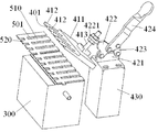
도 1은 본 발명의 예시적인 실시예에 따른 절단 시스템의 예시적인 사시도이며, 여기서 고정 디바이스(400)는 재료 플레이트의 시트(500)가 가압되는 잠금 상태에 있고; 도 2는 도 1의 절단 시스템의 지지대(300) 및 고정 디바이스(400)를 도시하는 예시적인 사시도이며, 여기서 고정 디바이스(400)는 재료 플레이트의 시트(500)가 방출되는 잠금해제 상태에 있다. Figure 1 is an exemplary perspective view of a cutting system in accordance with an exemplary embodiment of the present invention, wherein the
본 발명의 예시적인 실시예에서, 도 1 및 도 2에 도시된 바와 같이, 이동 기구(100), 레이저 절단기(200), 지지대(300) 및 고정 디바이스(400)를 주로 포함하는 절단 시스템이 개시된다. In an exemplary embodiment of the present invention, as shown in Figs. 1 and 2, a cutting system, which primarily comprises a
도 1 및 도 2에 도시된 바와 같이, 레이저 절단기(200)는 이동 기구(100) 상에 장착된다. 이동 기구(100)는 레이저 절단기(200)의 레이저 헤드를 프리셋 제어 프로그램에 기초하여 미리 결정된 궤도를 따라 이동시키게 구동하도록 구성된다. 재료 플레이트의 시트(500)를 절단하는 동안, 레이저 절단기(200)는 미리 결정된 궤도를 따라 재료 플레이트의 시트(500)를 절단하도록, 재료 플레이트의 시트(500) 상에 레이저 빔을 방출한다. 지지대(300)는 절단될 재료 플레이트의 시트(500)를 자신 위에서 지지하도록 구성된다. 고정 디바이스(400)는 절단될 재료 플레이트의 시트(500)를 지지대(300) 상에 고정하도록 구성된다. As shown in FIGS. 1 and 2, the
도 1 및 도 2를 다시 참조하면, 일 실시예에서, 고정 디바이스(400)는 가압 플레이트(410)를 포함하고, 가압 플레이트(410) 상에는 일련의 톱니-형 피처들(412)이 형성된다. 그 결과, 일련의 톱니 슬롯들(401)이 톱니-형 피처들(412) 사이에 정의된다. 레이저 절단기(200)로 재료 플레이트의 시트(500)를 절단하는 동안, 일련의 톱니-형 피처들(412)은 지지대(300) 상에서 재료 플레이트의 시트(500)를 가압하고, 이동 기구(100)는 단일 절단 프로세스에 의해 재료 플레이트의 시트(500)로부터 일련의 톱니-형 피처들(412)에 대응하는 일련의 워크피스들(510)을 절단하여 이를 형성하도록 톱니 슬롯들(401)의 에지를 따라 이동하게 레이저 절단기(200)의 레이저 헤드를 구동한다. Referring again to Figures 1 and 2, in one embodiment, the
본 발명의 예시적인 실시예에서, 재료 플레이트의 시트(500)는 금속 플레이트의 스트립(strip)일 수 있다. 금속 플레이트의 스트립으로 제조된 워크피스들(510)은 금속 콘택들일 수 있다. 도 2에 도시된 바와 같이, 재료 플레이트의 시트(500)는 재료 플레이트의 시트(500)를 로케이팅하고 운반하기 위한 에지 부분(520)을 가질 수 있다. 워크피스들(510)의 전달을 용이하게 하기 위해, 재료 플레이트의 시트(500)로 제조된 워크피스들(510)은 초기에 에지 부분(520)에 의해 서로 연결된다. 재료 플레이트의 시트(500)의 에지 부분(520)은 사용 시에 워크피스들(510)을 서로 분리시키도록 최종적으로 절단된다. In an exemplary embodiment of the invention, the sheet of
일 실시예에서, 도 1 및 2에 도시된 바와 같이, 일련의 톱니-형 피처들(412)은 크기 및 형상의 면에서 서로 동일하여, 재료 플레이트의 시트(500)로 제조된 일련의 워크피스들(510)이 크기 및 형상의 면에서 서로 동일하다. 그러나 본 발명은 이것으로 한정되는 것은 아니며, 일련의 톱니-형 피처들은 크기 및 형상의 면에서 서로 상이할 수 있어, 재료 플레이트의 시트로 제조된 일련의 워크피스들은 크기 및 형상의 면에서 서로 상이하게 한다. In one embodiment, as shown in FIGS. 1 and 2, a series of tooth-
도 1 및 도 2에 도시된 바와 같이, 고정 디바이스(400)는 지지대(300) 상에 포지셔닝된 재료 플레이트의 시트(500)를 가압 플레이트(410)로 가압하기 위해, 가압 플레이트(410) 상에 가압력을 부과하도록 구성되는 힘 부과 기구(force exerting mechanism)(420)를 더 포함할 수 있다. 1 and 2, the
일 실시예에서, 도 1 및 도 2에 도시된 바와 같이, 힘 부과 기구(420)는 제 1 연동 플레이트(421), 제 2 연동 플레이트(422), 제 3 연동 플레이트(423) 및 핸들(424)을 주로 포함한다. 제 1 연동 플레이트(421)는 정적인 베이스(430) 상에 고정되고 제 1 단부 및 제 2 단부를 갖는다. 제 2 연동 플레이트(422)는 제 1 코너, 제 2 코너 및 제 3 코너를 갖는다. 제 2 연동 플레이트(422)의 제 1 코너는 제 1 연동 플레이트(421)의 제 1 단부에 피봇 가능하게(pivotally) 연결된다. 제 3 연동 플레이트(423)는 제 1 단부 및 제 2 단부를 가지며, 제 3 연동 플레이트(423)의 제 1 단부는 제 1 연동 플레이트(421)의 제 2 단부에 피봇 가능하게 연결된다. 핸들(424)의 하나의 저부측은 제 2 연동 플레이트(422)의 제 2 코너에 피봇 가능하게 연결되고, 핸들(424)의 다른 저부측은 제 3 연동 플레이트(423)의 제 2 단부에 피봇 가능하게 연결된다. 가압 플레이트(410)는 제 2 연동 플레이트(422)의 제 3 코너에 고정 연결되며, 가압력은 핸들(424)을 회전시킴으로써 가압 플레이트(410)에 부과될 수 있다. 1 and 2, the
예시된 실시예에서, 힘 부과 기구(420)는 피봇 가능 접합부들이 제공된 평행 사변형 전달 기구를 포함한다. 그러나 본 발명은 이것으로 한정되는 것은 아니며, 힘 부과 기구는 에어 실린더 또는 유압 실린더를 포함할 수 있고, 에어 실린더 또는 유압 실린더의 피스톤 로드가 가압 플레이트 상에 가압력을 직접 부과할 수 있다. In the illustrated embodiment, the
도 1 및 도 2를 참조하면, 힘 부과 기구(420)는 재료 플레이트의 시트(500)가 가압되는 잠금 상태(도 1에 도시됨)와 재료 플레이트의 시트(500)가 방출되는 잠금해제 상태(도 2에 도시됨) 사이에서 전환되도록 구성된다. 도 1 및 도 2에 도시된 바와 같이, 힘 부과 기구(420)가 잠금 상태(도 1에 도시됨)로 전환될 때, 힘 부과 기구(420)의 제 2 연동 플레이트(422) 및 제 3 연동 플레이트(423)는, 마찰에 의해 서로 맞물려서, 힘 부과 기구(420)를 잠금 상태로 유지한다. 또한, 힘 부과 기구(420)가 잠금 상태(도 1에 도시됨)로 전환될 때, 핸들(424)은 가압 플레이트(410)와 실질적으로 평행한 수평 포지션(도 1에 도시됨)으로 회전된다. Referring to Figures 1 and 2, the
본 발명의 실시예에서, 도 1 및 도 2에 도시된 바와 같이, 가압 플레이트(410)는 연결 로드(413)가 제공되어 있는 플레이트 본체(411)를 포함하고, 연결 로드(413)는 스레드식 단부(threaded end)를 갖는다. 연결 부재(4221)는 제 2 연동 플레이트(422)의 제 3 코너 상에 제공되고 관통 구멍을 갖도록 형성된다. 연결 로드(413)의 스레드식 단부는 연결 부재(4221)의 관통 구멍을 통과하고 연결 부재(4221)의 양 측들 상에서 나사 결합되는 2개의 너트들에 의해 연결 부재(4221) 상에 잠금된다. 1 and 2, the
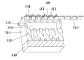
도 3은 도 1의 절단 시스템의 지지대(300) 및 고정 디바이스(400)의 단면도이며, 여기서 고정 디바이스(400)는 재료 플레이트의 시트(500)가 가압되는 잠금 상태에 있다. FIG. 3 is a cross-sectional view of the
도 1 내지 도 3에 도시된 바와 같이, 일 실시예에서, 지지대(300)는 챔버(350)가 형성되어 있는 본체(310)를 포함한다. 가압 플레이트(410)의 일련의 톱니 슬롯들(401)에 대응하는 일련의 재료 하강 슬롯들(material dropping slots)(301)이 챔버(350)의 최상부 벽에 형성된다. 챔버(350)의 최상부 벽에 있는 일련의 재료 하강 슬롯들(301)을 통해, 재료 플레이트의 시트(500)로부터 절단된 폐기 재료가 챔버(350) 내로 떨어지고, 재료 플레이트의 시트(500)를 절단하는 동안 생성된 연기 및 먼지가 챔버(350) 내로 들어간다. 1 to 3, in one embodiment, the
도 3에 도시된 바와 같이, 절단 시스템은 챔버(350)로부터의 연기 및 먼지를 흡입하도록 챔버(350)의 측벽으로부터 챔버(350) 내로 연장되는 진공 흡입관(320)을 갖는 진공 흡입기를 더 포함한다. 3, the cutting system further includes a vacuum inhaler having a
도 3을 다시 참조하면, 일련의 재료 하강 슬롯들(301)에 대응하는 일련의 재료 수집 슬롯들(330)이 챔버(350)의 저부 벽에 형성된다. 재료 하강 슬롯들(301)을 통해 챔버(350)로 떨어지는 폐기 재료는 재료 수집 슬롯들(330)에서 수집된다. 일 실시예에서, 재료 수집 슬롯(330)은 재료 하강 슬롯(301)을 향하는 더 큰 개구 및 더 큰 개구에 반대편에 더 작은 개구를 갖는 트럼펫 형상을 나타낸다. Referring again to FIG. 3, a series of
도 3을 다시 참조하면, 일 실시예에서, 지지대(300)는 지지대(300)의 본체(310)의 저부 상에 제공된 저부 커버(340)를 더 포함한다. 재료 수집 슬롯들(330)에 수집된 폐기 재료는 저부 커버(340)가 개방된 후에 재료 수집 슬롯들(330)의 더 작은 개구들을 통해 배출된다. Referring again to FIG. 3, in one embodiment, the
일 실시예에서, 도 1에 도시된 바와 같이, 이동 기구(100)는 다-자유도 로봇, 예를 들어 4개, 5개 또는 6개의 자유도들을 갖는 로봇을 포함할 수 있다. 레이저 절단기(200)는 다-자유도 로봇의 단부 아암 상에 장착되고 지지대(300)의 최상부 표면 위에 로케이팅될 수 있다. In one embodiment, as shown in FIG. 1, the moving
위의 실시예들은 제한적이 아니라 예시적인 것으로 의도된다는 것이 당업자들에게 인지되어야 한다. 예를 들어, 당업자들에 의해 위의 실시예들에 대한 다수의 수정들이 이루어질 수 있고, 상이한 실시예들에서 설명되는 다양한 특징들은 구성 또는 원리에서 충돌함 없이 서로 자유롭게 결합될 수 있다. It should be appreciated by those skilled in the art that the above embodiments are intended to be illustrative rather than restrictive. For example, numerous modifications may be made to the embodiments above by those skilled in the art, and the various features described in the different embodiments may be freely combined with one another without conflict in construction or principle.
몇 개의 예시적인 실시예들이 도시되고 설명되었지만, 다양한 변경들 또는 수정들이 본 개시의 원리들 및 사상으로부터 벗어남 없이 이들 실시예들에서 이루어질 수 있다는 것이 당업자에 의해 인지될 것이며, 본 개시의 범위는 청구항 및 그의 등가물들에서 정의된다. While a few exemplary embodiments have been shown and described, it will be appreciated by those skilled in the art that various changes or modifications can be made in these embodiments without departing from the principles and spirit of the present disclosure, And its equivalents.
본원에서 이용되는 바와 같이, 단수로 인용되고 단수표현으로 제기되는 엘리먼트들은, 복수의 상기 엘리먼트들 또는 단계들의 배제가 명시적으로 언급되지 않는다면, 이들을 배제하지 않는 것으로서 이해되어야 한다. 또한, 본 발명의 "일 실시예"에 대한 참조들은 인용된 특징들을 또한 포함하는 부가적인 실시예들의 존재를 배제하는 것으로서 해석되는 것으로 의도되지 않는다. 또한, 그 반대가 명시적으로 언급되지 않으면, 특정한 특성을 갖는 엘리먼트 또는 복수의 엘리먼트들을 "포함하고" 또는 "갖는" 실시예들은 그 특성을 갖지 않는 부가적인 이러한 엘리먼트들을 포함할 수 있다. As used herein, elements referred to in the singular and appearing in the singular are to be understood as not excluding, unless an exclusion of a plurality of such elements or steps is explicitly mentioned. Further, references to "one embodiment" of the present invention are not intended to be construed as excluding the existence of additional embodiments which also include the recited features. Also, unless the contrary is expressly stated, embodiments having "having" or "having" a particular characteristic or a plurality of elements may include additional such elements without that characteristic.
Claims (17)
이동 기구;
상기 이동 기구 상에 장착되는 레이저 절단기;
절단될 재료 플레이트의 시트(sheet)를 자신 위에서 지지하도록 구성되는 지지대(support table); 및
상기 절단될 재료 플레이트의 시트를 상기 지지대 상에 고정하도록 구성되는 고정 디바이스를 포함하고,
상기 고정 디바이스는 인접한 톱니-형 피처들(tooth-like features) 사이에 규정되는 톱니 슬롯(tooth slot)과 더불어 일련의(a row of) 톱니-형 피처들을 갖는 가압 플레이트(pressing plate)를 포함하고,
상기 레이저 절단기로 상기 재료 플레이트의 시트를 절단하는 동안, 상기 일련의 톱니-형 피처들은 상기 지지대 상에서 상기 재료 플레이트의 시트를 가압하고, 상기 이동 기구는 단일 절단 프로세스에 의해 상기 재료 플레이트의 시트로부터, 상기 일련의 톱니-형 피처들에 대응하는 일련의 워크피스들(work pieces)을 절단하도록 상기 톱니 슬롯들의 에지들을 따라 이동하게 상기 레이저 절단기의 레이저 헤드를 구동하는,
절단 시스템.
As a cutting system,
A moving mechanism;
A laser cutter mounted on the moving mechanism;
A support table configured to support a sheet of material plate to be cut on itself; And
And a securing device configured to secure a sheet of material plate to be cut on said support,
The fastening device includes a pressing plate having a row of serrated features along with a tooth slot defined between adjacent tooth-like features, ,
The series of serration-type features presses the sheet of material plate on the support while cutting the sheet of material plate with the laser cutter, the movement mechanism being movable from a sheet of material plate by a single cutting process, Driving the laser head of the laser cutter to move along the edges of the sawtooth slots to cut a series of work pieces corresponding to the series of serrated features,
Cutting system.
상기 재료 플레이트의 시트는 금속 플레이트의 스트립(strip)인,
절단 시스템.
The method according to claim 1,
Wherein the sheet of material plate is a strip of metal plate,
Cutting system.
상기 일련의 톱니-형 피처들은 크기 및 형상의 면에서 서로 동일하여, 상기 재료 플레이트의 시트로 제조된 상기 일련의 워크피스들이 크기 및 형상의 면에서 서로 동일한,
절단 시스템.
The method according to claim 1,
Said series of serrated features being identical to each other in terms of size and shape so that said series of workpieces made of a sheet of material plate are identical to each other in terms of size and shape,
Cutting system.
상기 일련의 톱니-형 피처들은 크기 및 형상의 면에서 서로 상이하여, 상기 재료 플레이트의 시트로 제조된 상기 일련의 워크피스들이 크기 및 형상의 면에서 서로 상이한,
절단 시스템.
The method according to claim 1,
Wherein the series of serration-like features are different from one another in terms of size and shape so that the series of workpieces made of the sheet of material plate are different from one another in terms of size and shape,
Cutting system.
상기 고정 디바이스는, 상기 가압 플레이트 상에 가압력을 부과하여 상기 가압 플레이트로 상기 지지대 상에서 상기 재료 플레이트의 시트를 가압하도록 구성된 힘 부과 기구(force exerting mechanism)을 더 포함하는,
절단 시스템.
The method according to claim 1,
Wherein the holding device further comprises a force exerting mechanism configured to apply a pressing force on the pressing plate to press the sheet of material plate on the supporting plate with the pressing plate.
Cutting system.
상기 힘 부과 기구는,
정적인 베이스(stationary base) 상에 고정되고 제 1 단부 및 제 2 단부를 갖는 제 1 연동 플레이트(linking plate);
제 1 코너, 제 2 코너 및 제 3 코너를 갖는 제 2 연동 플레이트 ― 상기 제 2 연동 플레이트의 제 1 코너는 상기 제 1 연동 플레이트의 제 1 단부에 피봇 가능하게(pivotally) 연결됨 ― ;
제 1 단부 및 제 2 단부를 갖는 제 3 연동 플레이트 ― 상기 제 3 연동 플레이트의 제 1 단부는 상기 제 1 연동 플레이트의 제 2 단부에 피봇 가능하게 연결됨 ― ; 및
핸들을 포함하고,
상기 핸들의 하나의 저부측은 상기 제 2 연동 플레이트의 제 2 코너에 피봇 가능하게 연결되고, 상기 핸들의 다른 저부측은 상기 제 3 연동 플레이트의 제 2 단부에 피봇 가능하게 연결되고;
상기 가압 플레이트는 상기 제 2 연동 플레이트의 제 3 코너에 고정 연결되며, 상기 가압력은 상기 핸들을 회전시킴으로써 상기 가압 플레이트에 부과되는,
절단 시스템.
6. The method of claim 5,
The force applying mechanism includes:
A first interlocking plate fixed on a stationary base and having a first end and a second end;
A second interlocking plate having a first corner, a second corner and a third corner, wherein a first corner of the second interlocking plate is pivotally connected to a first end of the first interlocking plate;
A third interlocking plate having a first end and a second end, the first end of the third interlocking plate being pivotally connected to the second end of the first interlocking plate; And
Including a handle,
One bottom side of the handle being pivotally connected to a second corner of the second interlocking plate and the other bottom side of the handle being pivotally connected to the second end of the third interlocking plate;
Wherein the pressing plate is fixedly connected to a third corner of the second interlocking plate and the pressing force is applied to the pressing plate by rotating the handle,
Cutting system.
상기 힘 부과 기구는 상기 재료 플레이트의 시트가 가압되는 잠금 상태와 상기 재료 플레이트의 시트가 방출되는(released) 잠금해제 상태 사이에서 전환되도록 구성되는,
절단 시스템.
The method according to claim 6,
Wherein the force applying mechanism is configured to switch between a locked state in which a sheet of the material plate is pressed and an unlocked state in which a sheet of the material plate is released,
Cutting system.
상기 힘 부과 기구가 상기 잠금 상태로 전환될 때, 상기 힘 부과 기구의 제 2 연동 플레이트 및 제 3 연동 플레이트는 상기 힘 부과 기구를 상기 잠금 상태로 유지하도록 마찰에 의해 서로 맞물리는(engaged),
절단 시스템.
8. The method of claim 7,
Wherein the second interlocking plate and the third interlocking plate of the force applying mechanism are engaged with each other by friction to maintain the force applying mechanism in the locked state when the force applying mechanism is switched to the locked state,
Cutting system.
상기 힘 부과 기구가 상기 잠금 상태로 전환될 때, 상기 핸들은 상기 가압 플레이트에 대해 실질적으로 평행한 수평 포지션으로 회전되고 유지되는,
절단 시스템.
9. The method of claim 8,
Wherein when the force applying mechanism is switched to the locked state, the handle is rotated and held in a horizontal position substantially parallel to the pressing plate,
Cutting system.
상기 가압 플레이트는 연결 로드(connection rod)가 제공되어 있는 플레이트 본체를 포함하고, 상기 연결 로드는 스레드식 단부(threaded end)를 갖고;
연결 부재가 상기 제 2 연동 플레이트의 제 3 코너 상에 제공되고 관통 구멍을 갖도록 형성되고; 그리고
상기 연결 로드의 스레드식 단부는 상기 연결 부재의 관통 구멍을 통과하고 상기 연결 부재의 양 측들 상에서 나사 결합되는 2개의 너트들에 의해 상기 연결 부재 상에 잠금되는,
절단 시스템.
The method according to claim 6,
Wherein the pressure plate comprises a plate body provided with a connection rod, the connection rod having a threaded end;
A connecting member is provided on the third corner of the second interlocking plate and is formed to have a through-hole; And
Wherein the threaded end of the connecting rod is locked on the connecting member by two nuts passing through the through hole of the connecting member and screwed on both sides of the connecting member,
Cutting system.
상기 힘 부과 기구는 에어(air) 실린더 또는 유압 실린더를 포함하고, 상기 에어 실린더 또는 상기 유압 실린더의 피스톤 로드는 상기 가압 플레이트 상에 가압력을 직접 부과하는,
절단 시스템.
6. The method of claim 5,
Wherein the force applying mechanism includes an air cylinder or a hydraulic cylinder and the piston rod of the air cylinder or the hydraulic cylinder directly applies a pressing force on the pressing plate,
Cutting system.
상기 지지대는 챔버가 형성되어 있는 본체를 포함하고;
상기 가압 플레이트의 일련의 톱니 슬롯들에 대응하는 일련의 재료 하강 슬롯들(material dropping slots)이 상기 챔버의 최상부(top) 벽에 형성되고;
상기 챔버의 최상부 벽에 있는 상기 일련의 재료 하강 슬롯들을 통해, 상기 재료 플레이트의 시트로부터 절단된 폐기 재료가 상기 챔버 내로 떨어지고, 상기 재료 플레이트의 시트를 절단하는 동안 생성된 연기 및 먼지가 상기 챔버 내로 들어가는,
절단 시스템.
The method according to claim 1,
The support includes a body in which a chamber is formed;
A series of material dropping slots corresponding to a series of tooth slots of the pressing plate are formed in the top wall of the chamber;
Wherein waste material cut from a sheet of the material plate falls into the chamber through the series of material drop slots in the top wall of the chamber and fumes and dust generated during cutting the sheet of material plate into the chamber Entering,
Cutting system.
상기 챔버로부터 상기 연기 및 먼지를 흡입하도록, 상기 챔버의 측벽으로부터 상기 챔버 내로 연장되는 진공 흡입관을 갖는 진공 흡입기(vacuum sucker)를 더 포함하는,
절단 시스템.
13. The method of claim 12,
Further comprising a vacuum sucker having a vacuum suction line extending from the side wall of the chamber into the chamber to draw in the smoke and dust from the chamber.
Cutting system.
상기 일련의 재료 하강 슬롯들에 대응하는 일련의 재료 수집 슬롯들이 상기 챔버의 저부 벽에 형성되고; 그리고
상기 재료 하강 슬롯들을 통해 상기 챔버로 떨어지는 폐기 재료는 상기 재료 수집 슬롯들에서 수집되는,
절단 시스템.
14. The method of claim 13,
A series of material collection slots corresponding to the series of material drop slots are formed in the bottom wall of the chamber; And
Wherein waste material falling into the chamber through the material falling slots is collected in the material collection slots,
Cutting system.
상기 재료 수집 슬롯은 상기 재료 하강 슬롯을 마주하는 더 큰 개구 및 상기 더 큰 개구에 반대편에 더 작은 개구를 갖는 트럼펫 형상(trumpet shape)을 나타내는,
절단 시스템.
15. The method of claim 14,
The material collection slot having a larger opening facing the material falling slot and a trumpet shape having a smaller opening on the opposite side to the larger opening,
Cutting system.
상기 지지대는 상기 지지대의 본체의 저부 상에 제공된 저부 커버를 더 포함하고,
상기 재료 수집 슬롯들에서 수집된 상기 폐기 재료는 상기 저부 커버가 개방된 후에 상기 재료 수집 슬롯들의 더 작은 개구들을 통해 배출되는,
절단 시스템.
16. The method of claim 15,
The support further comprises a bottom cover provided on the bottom of the body of the support,
Wherein the waste material collected in the material collection slots is discharged through smaller openings in the material collection slots after the bottom cover is opened,
Cutting system.
상기 이동 기구는 다-자유도 로봇(multi-freedom robot)을 포함하고, 상기 레이저 절단기는 상기 다-자유도 로봇의 단부 아암(end arm) 상에 장착되는,
절단 시스템.
The method according to claim 1,
Wherein the moving mechanism comprises a multi-freedom robot, and the laser cutter is mounted on an end arm of the multi-degree of freedom robot,
Cutting system.
Applications Claiming Priority (3)
| Application Number | Priority Date | Filing Date | Title |
|---|---|---|---|
| CN201410791172.5 | 2014-12-18 | ||
| CN201410791172.5A CN105750737B (en) | 2014-12-18 | 2014-12-18 | Diced system |
| PCT/IB2015/059732 WO2016098047A1 (en) | 2014-12-18 | 2015-12-17 | Cutting system |
Publications (2)
| Publication Number | Publication Date |
|---|---|
| KR20170097715A true KR20170097715A (en) | 2017-08-28 |
| KR102501154B1 KR102501154B1 (en) | 2023-02-16 |
Family
ID=55173866
Family Applications (1)
| Application Number | Title | Priority Date | Filing Date |
|---|---|---|---|
| KR1020177019865A KR102501154B1 (en) | 2014-12-18 | 2015-12-17 | Cutting system |
Country Status (6)
| Country | Link |
|---|---|
| US (1) | US10702957B2 (en) |
| EP (1) | EP3233363B1 (en) |
| JP (1) | JP6425802B2 (en) |
| KR (1) | KR102501154B1 (en) |
| CN (1) | CN105750737B (en) |
| WO (1) | WO2016098047A1 (en) |
Families Citing this family (2)
| Publication number | Priority date | Publication date | Assignee | Title |
|---|---|---|---|---|
| CN108056488A (en) * | 2018-01-02 | 2018-05-22 | 深圳润丰投资咨询有限公司 | A kind of feed granules processing unit (plant) |
| JP7002677B2 (en) * | 2018-11-13 | 2022-01-20 | 本田技研工業株式会社 | Laser processing equipment |
Citations (4)
| Publication number | Priority date | Publication date | Assignee | Title |
|---|---|---|---|---|
| JPH05245681A (en) * | 1992-03-06 | 1993-09-24 | Fuji Heavy Ind Ltd | Laser beam machine |
| JPH08243777A (en) * | 1995-03-13 | 1996-09-24 | Hideo Nakagawa | Metal filter cutting method and device therefor |
| KR101040660B1 (en) * | 2011-01-14 | 2011-06-10 | (주)스페이스원 | Cnc plasma model cutter with improved dust-collection efficiency |
| KR20130069202A (en) * | 2011-12-16 | 2013-06-26 | 주식회사 성우하이텍 | Jig apparatus for laser welding |
Family Cites Families (51)
| Publication number | Priority date | Publication date | Assignee | Title |
|---|---|---|---|---|
| US2456100A (en) * | 1945-06-04 | 1948-12-14 | Justice W Wood | Toggle clamp |
| US3924844A (en) * | 1974-07-29 | 1975-12-09 | Wright Barry Corp | Toggle clamp lock |
| US4382728A (en) * | 1979-10-25 | 1983-05-10 | The Boeing Company | Workpiece retaining pressure-foot assembly for orthogonally movable machine tool |
| US4335873A (en) * | 1980-05-21 | 1982-06-22 | C. J. Edwards Company | Toggle bolt clamp |
| DE3816692A1 (en) * | 1988-05-17 | 1989-11-30 | Matthias Fischer | Resilient pressure pot, in particular for toggle-lever gripping devices |
| CN2112471U (en) * | 1991-11-20 | 1992-08-12 | 国家建筑材料工业局南京玻璃纤维研究设计院 | Full antomatic holding device for laser welding platinum alloy leak plate |
| JPH08192289A (en) * | 1995-01-12 | 1996-07-30 | Toshiba Corp | Laser beam machining device |
| US5922225A (en) * | 1996-03-06 | 1999-07-13 | Blake; Ronald J. | Apparatus for reducing vaporized material deposits during laser cutting |
| US5763852A (en) * | 1996-09-04 | 1998-06-09 | W.A. Whitney Co. | Punch press with auxillary high-energy thermal cutting device and improved slag collection system |
| US5924685A (en) * | 1997-06-16 | 1999-07-20 | Webb; Robert M. | Adjustable clamp |
| US5906760A (en) * | 1997-11-04 | 1999-05-25 | Robb; David K. | Exhaust system for a laser cutting device |
| GB2332637B (en) * | 1997-12-25 | 2000-03-08 | Matsushita Electric Ind Co Ltd | Apparatus and method for processing |
| EP1148588A3 (en) * | 2000-01-31 | 2001-11-14 | Tyco Electronics AMP GmbH | Contact socket |
| US6455805B1 (en) * | 2001-01-17 | 2002-09-24 | Advanced Micro Devices, Inc. | Tray mask plate for laser-trimming apparatus |
| US7763826B2 (en) * | 2001-12-18 | 2010-07-27 | Meir Chen | System and method for cutting and applying metal configurations to another metal surface |
| KR100956072B1 (en) * | 2002-07-25 | 2010-05-07 | 니시무라 프레스 코규쇼 가부시키가이샤 | Clamp device |
| NL1021622C2 (en) * | 2002-10-10 | 2004-04-14 | Wemo Nederland Bv | Laser cutting device for sheet material, includes two fixing devices for holding product in input, processing and output regions |
| EP1433571B1 (en) * | 2002-12-28 | 2005-08-10 | Heinrich Kipp Werk Spanntechnik + Normelemente | Clamping device |
| WO2004065055A1 (en) * | 2003-01-21 | 2004-08-05 | Toyota Steel Center Co., Ltd. | Laser cutting device, laser cutting method, and laser cutting system |
| US7857020B2 (en) * | 2004-07-30 | 2010-12-28 | Black & Decker Inc. | Jig apparatus |
| CN2764548Y (en) * | 2005-01-24 | 2006-03-15 | 彩虹集团电子股份有限公司 | Press plate for laser welding |
| US20060249228A1 (en) * | 2005-05-06 | 2006-11-09 | Hart Design, Inc. | Dovetail jig |
| DE102005035846A1 (en) * | 2005-07-30 | 2007-02-08 | GM Global Technology Operations, Inc., Detroit | Pressure device for a clamping system |
| US7648131B2 (en) * | 2005-11-04 | 2010-01-19 | Delaware Capital Foundation, Inc. | Horizontal hold down clamp |
| CA2611230A1 (en) * | 2006-11-20 | 2008-05-20 | Leigh Industries Ltd. | Joint making jig |
| EP2122451A4 (en) * | 2007-02-13 | 2011-08-03 | Paul H Nye | A personal affector machine |
| WO2009009187A1 (en) * | 2007-06-15 | 2009-01-15 | Johnson Controls - Saft Advanced Power Solutions Llc | Laser cutting system |
| CN201136098Y (en) * | 2007-12-10 | 2008-10-22 | 西北有色金属研究院 | Forming appliance for precision short tubes |
| JP5532929B2 (en) * | 2008-02-08 | 2014-06-25 | 日立化成株式会社 | Optical wiring printed circuit board manufacturing method |
| CN101804510A (en) * | 2009-02-14 | 2010-08-18 | 陈新建 | Double-funnel type medium-pressure smoke discharging device for laser engraving (cutting) machine |
| CN201483155U (en) * | 2009-07-29 | 2010-05-26 | 比亚迪股份有限公司 | Laser machining device |
| CN101777640B (en) * | 2010-02-10 | 2014-06-11 | 奇瑞汽车股份有限公司 | Laser cutting device of power battery pole piece |
| CN201807839U (en) * | 2010-09-06 | 2011-04-27 | 北京东明兴业科技有限公司 | Fixture for laser welding between lower sliding plate and nut of mobile phone |
| CN101972893B (en) * | 2010-10-29 | 2015-04-15 | 武汉金运激光股份有限公司 | Worktable of laser cutting machine |
| CN102642089B (en) * | 2011-02-18 | 2014-12-31 | 深圳市吉阳自动化科技有限公司 | Pole piece laser cutting machine |
| CN102139416A (en) * | 2011-03-22 | 2011-08-03 | 无锡太博泵业有限公司 | Mould for welding impeller |
| CN202037425U (en) * | 2011-03-22 | 2011-11-16 | 无锡太博泵业有限公司 | Die used for impeller welding |
| CN102152008A (en) * | 2011-03-22 | 2011-08-17 | 无锡太博泵业有限公司 | Impeller welding die |
| CN202021443U (en) * | 2011-03-22 | 2011-11-02 | 无锡太博泵业有限公司 | Mold for welding impeller |
| CN202015918U (en) * | 2011-03-29 | 2011-10-26 | 三星高新电机(天津)有限公司 | Printed circuit board product arraying pallet |
| CN102284796B (en) * | 2011-06-07 | 2015-03-11 | 大族激光科技产业集团股份有限公司 | Method for processing window on covering film |
| CN102554818A (en) * | 2011-12-08 | 2012-07-11 | 苏州工业园区高登威科技有限公司 | Mounting fixture with slide track positioning judging function |
| CN202726323U (en) * | 2012-06-26 | 2013-02-13 | 常州华日升反光材料股份有限公司 | Sheet laser welding working table |
| CN203236513U (en) * | 2013-01-15 | 2013-10-16 | 吉祥资源科技股份有限公司 | Cutting device for recovered dialysis tubing |
| CN103177836B (en) * | 2013-03-16 | 2016-07-13 | 东莞市安培龙电子科技有限公司 | Adopt critesistor and the manufacture method thereof of ceramic membrane manufacture |
| CN104175005B (en) * | 2013-05-28 | 2017-10-03 | 日本车辆制造株式会社 | Thin plate holding meanss |
| CN203390458U (en) * | 2013-07-31 | 2014-01-15 | 广东欧珀移动通信有限公司 | Digital product metal housing welding fixture |
| CN203712075U (en) * | 2014-02-27 | 2014-07-16 | 长沙星沙机床有限公司 | Laser processing machine tool |
| CN203817635U (en) * | 2014-03-27 | 2014-09-10 | 深圳市大族激光科技股份有限公司 | Laser processing device with adsorption structure |
| CN203918241U (en) * | 2014-04-21 | 2014-11-05 | 东莞市盛雄激光设备有限公司 | A kind of jig for laser cutting |
| CN104096980B (en) * | 2014-06-26 | 2016-01-20 | 长春光华微电子设备工程中心有限公司 | laser cutting vacuum absorbing platform |
-
2014
- 2014-12-18 CN CN201410791172.5A patent/CN105750737B/en active Active
-
2015
- 2015-12-17 EP EP15825849.1A patent/EP3233363B1/en active Active
- 2015-12-17 KR KR1020177019865A patent/KR102501154B1/en active IP Right Grant
- 2015-12-17 JP JP2017515143A patent/JP6425802B2/en not_active Expired - Fee Related
- 2015-12-17 WO PCT/IB2015/059732 patent/WO2016098047A1/en active Application Filing
-
2017
- 2017-06-14 US US15/622,706 patent/US10702957B2/en active Active
Patent Citations (4)
| Publication number | Priority date | Publication date | Assignee | Title |
|---|---|---|---|---|
| JPH05245681A (en) * | 1992-03-06 | 1993-09-24 | Fuji Heavy Ind Ltd | Laser beam machine |
| JPH08243777A (en) * | 1995-03-13 | 1996-09-24 | Hideo Nakagawa | Metal filter cutting method and device therefor |
| KR101040660B1 (en) * | 2011-01-14 | 2011-06-10 | (주)스페이스원 | Cnc plasma model cutter with improved dust-collection efficiency |
| KR20130069202A (en) * | 2011-12-16 | 2013-06-26 | 주식회사 성우하이텍 | Jig apparatus for laser welding |
Also Published As
| Publication number | Publication date |
|---|---|
| US20170274483A1 (en) | 2017-09-28 |
| EP3233363A1 (en) | 2017-10-25 |
| US10702957B2 (en) | 2020-07-07 |
| WO2016098047A1 (en) | 2016-06-23 |
| EP3233363B1 (en) | 2020-10-07 |
| JP2017529244A (en) | 2017-10-05 |
| JP6425802B2 (en) | 2018-11-21 |
| CN105750737B (en) | 2018-01-09 |
| KR102501154B1 (en) | 2023-02-16 |
| CN105750737A (en) | 2016-07-13 |
Similar Documents
| Publication | Publication Date | Title |
|---|---|---|
| US4162641A (en) | Automatic loading and unloading for numerically controlled turret punch | |
| JP7068150B2 (en) | Hand, robot system and work removal method | |
| JP6117755B2 (en) | Device, robot, and robot system for releasing catch of substrate cut in advance | |
| KR20170097715A (en) | Cutting system | |
| JP6635344B2 (en) | Cutting equipment for cutting paper, corrugated cardboard, plastics, composites or such relatively rigid materials | |
| JP2012232317A (en) | Fastener driving device | |
| JP6884425B2 (en) | Board splitting device | |
| EP2944409A1 (en) | Machine for cutting wood or plastic panels | |
| JP2810459B2 (en) | Plate positioning device | |
| EP3625001B1 (en) | Workpiece gripping device | |
| KR840006156A (en) | Combined shear and punch press | |
| EP3401278B1 (en) | Drawing device and drawing method | |
| EP1738883A2 (en) | Cardboard working machine | |
| KR20010071110A (en) | Universal ejection tool | |
| JPS63299826A (en) | Method and device for positioning origin of plate stock | |
| KR101451034B1 (en) | A coupling device for worktable | |
| EP3263324A1 (en) | A machine for forming boxes | |
| WO2018038224A1 (en) | Blank material separation device and blank material separation system using same | |
| KR200490110Y1 (en) | Reusable cover for t-type groove | |
| JP2019011776A (en) | Cam device and pick-and-place unit | |
| EP2944408A1 (en) | Machine for cutting wood or plastic panels | |
| JP4198425B2 (en) | Cardboard sheet cutting device | |
| TR201607607A2 (en) | A COMPOSITE PANEL CUTTING AND PROCESSING MACHINE | |
| TWI417157B (en) | Gripping device | |
| KR20170072743A (en) | Apparatus and method for processing groove of heat insulating materials and heat insulating materials using the same |
Legal Events
| Date | Code | Title | Description |
|---|---|---|---|
| A201 | Request for examination | ||
| E902 | Notification of reason for refusal | ||
| E90F | Notification of reason for final refusal | ||
| E701 | Decision to grant or registration of patent right | ||
| GRNT | Written decision to grant |