KR20170076546A - Coated steel sheet - Google Patents
Coated steel sheet Download PDFInfo
- Publication number
- KR20170076546A KR20170076546A KR1020160157102A KR20160157102A KR20170076546A KR 20170076546 A KR20170076546 A KR 20170076546A KR 1020160157102 A KR1020160157102 A KR 1020160157102A KR 20160157102 A KR20160157102 A KR 20160157102A KR 20170076546 A KR20170076546 A KR 20170076546A
- Authority
- KR
- South Korea
- Prior art keywords
- plating layer
- cooling
- steel sheet
- plating
- layer
- Prior art date
Links
- 229910000831 Steel Inorganic materials 0.000 title claims abstract description 274
- 239000010959 steel Substances 0.000 title claims abstract description 274
- 238000007747 plating Methods 0.000 claims abstract description 349
- 238000001816 cooling Methods 0.000 claims description 260
- 239000010410 layer Substances 0.000 claims description 254
- 238000000034 method Methods 0.000 claims description 31
- 229910017706 MgZn Inorganic materials 0.000 claims description 14
- 238000009826 distribution Methods 0.000 claims description 14
- 239000002344 surface layer Substances 0.000 claims description 9
- 239000002245 particle Substances 0.000 claims description 7
- 238000010586 diagram Methods 0.000 claims description 5
- 229910018134 Al-Mg Inorganic materials 0.000 claims description 3
- 229910018467 Al—Mg Inorganic materials 0.000 claims description 3
- 238000003618 dip coating Methods 0.000 claims description 3
- 239000004744 fabric Substances 0.000 claims description 3
- 229910045601 alloy Inorganic materials 0.000 claims description 2
- 239000000956 alloy Substances 0.000 claims description 2
- 238000007731 hot pressing Methods 0.000 claims description 2
- 239000013078 crystal Substances 0.000 abstract description 6
- 239000007788 liquid Substances 0.000 description 71
- 239000011701 zinc Substances 0.000 description 65
- IJGRMHOSHXDMSA-UHFFFAOYSA-N Atomic nitrogen Chemical compound N#N IJGRMHOSHXDMSA-UHFFFAOYSA-N 0.000 description 32
- 230000000052 comparative effect Effects 0.000 description 28
- 230000008569 process Effects 0.000 description 20
- 239000007789 gas Substances 0.000 description 17
- 238000003825 pressing Methods 0.000 description 17
- 229910052757 nitrogen Inorganic materials 0.000 description 16
- 230000007547 defect Effects 0.000 description 15
- 230000008021 deposition Effects 0.000 description 13
- 230000007797 corrosion Effects 0.000 description 12
- 238000005260 corrosion Methods 0.000 description 12
- 229910052751 metal Inorganic materials 0.000 description 12
- 239000002184 metal Substances 0.000 description 12
- 230000001276 controlling effect Effects 0.000 description 11
- 239000003507 refrigerant Substances 0.000 description 11
- 229910052725 zinc Inorganic materials 0.000 description 11
- HCHKCACWOHOZIP-UHFFFAOYSA-N Zinc Chemical compound [Zn] HCHKCACWOHOZIP-UHFFFAOYSA-N 0.000 description 10
- 238000010791 quenching Methods 0.000 description 10
- 239000011777 magnesium Substances 0.000 description 9
- 238000004519 manufacturing process Methods 0.000 description 9
- 239000000919 ceramic Substances 0.000 description 8
- 238000005246 galvanizing Methods 0.000 description 8
- 239000001307 helium Substances 0.000 description 8
- 229910052734 helium Inorganic materials 0.000 description 8
- SWQJXJOGLNCZEY-UHFFFAOYSA-N helium atom Chemical compound [He] SWQJXJOGLNCZEY-UHFFFAOYSA-N 0.000 description 8
- 230000000171 quenching effect Effects 0.000 description 7
- 238000012360 testing method Methods 0.000 description 7
- 239000011248 coating agent Substances 0.000 description 6
- 239000011247 coating layer Substances 0.000 description 6
- 238000000576 coating method Methods 0.000 description 6
- 230000008520 organization Effects 0.000 description 6
- 230000003746 surface roughness Effects 0.000 description 6
- 239000002826 coolant Substances 0.000 description 5
- 238000001514 detection method Methods 0.000 description 5
- 229910052749 magnesium Inorganic materials 0.000 description 5
- 229910052782 aluminium Inorganic materials 0.000 description 4
- 230000000694 effects Effects 0.000 description 4
- 239000007769 metal material Substances 0.000 description 4
- 238000005452 bending Methods 0.000 description 3
- 239000000356 contaminant Substances 0.000 description 3
- 238000000635 electron micrograph Methods 0.000 description 3
- 229910001092 metal group alloy Inorganic materials 0.000 description 3
- 238000012545 processing Methods 0.000 description 3
- XKRFYHLGVUSROY-UHFFFAOYSA-N Argon Chemical compound [Ar] XKRFYHLGVUSROY-UHFFFAOYSA-N 0.000 description 2
- 229910001335 Galvanized steel Inorganic materials 0.000 description 2
- FYYHWMGAXLPEAU-UHFFFAOYSA-N Magnesium Chemical compound [Mg] FYYHWMGAXLPEAU-UHFFFAOYSA-N 0.000 description 2
- 238000002441 X-ray diffraction Methods 0.000 description 2
- 230000005856 abnormality Effects 0.000 description 2
- 230000002411 adverse Effects 0.000 description 2
- XAGFODPZIPBFFR-UHFFFAOYSA-N aluminium Chemical compound [Al] XAGFODPZIPBFFR-UHFFFAOYSA-N 0.000 description 2
- 230000008859 change Effects 0.000 description 2
- 230000007423 decrease Effects 0.000 description 2
- 238000002474 experimental method Methods 0.000 description 2
- 239000008397 galvanized steel Substances 0.000 description 2
- 230000006872 improvement Effects 0.000 description 2
- 230000001788 irregular Effects 0.000 description 2
- 239000000463 material Substances 0.000 description 2
- 150000002739 metals Chemical class 0.000 description 2
- 238000009828 non-uniform distribution Methods 0.000 description 2
- 230000001590 oxidative effect Effects 0.000 description 2
- 230000001105 regulatory effect Effects 0.000 description 2
- 150000003839 salts Chemical class 0.000 description 2
- 238000007711 solidification Methods 0.000 description 2
- 230000008023 solidification Effects 0.000 description 2
- 239000007921 spray Substances 0.000 description 2
- 238000012935 Averaging Methods 0.000 description 1
- 230000002159 abnormal effect Effects 0.000 description 1
- 238000005299 abrasion Methods 0.000 description 1
- 238000013459 approach Methods 0.000 description 1
- 229910052786 argon Inorganic materials 0.000 description 1
- 239000004566 building material Substances 0.000 description 1
- 238000006243 chemical reaction Methods 0.000 description 1
- 239000010960 cold rolled steel Substances 0.000 description 1
- 238000007796 conventional method Methods 0.000 description 1
- 239000000112 cooling gas Substances 0.000 description 1
- 238000005336 cracking Methods 0.000 description 1
- 230000006866 deterioration Effects 0.000 description 1
- 238000007598 dipping method Methods 0.000 description 1
- 239000000428 dust Substances 0.000 description 1
- 238000001914 filtration Methods 0.000 description 1
- 238000010438 heat treatment Methods 0.000 description 1
- 239000012535 impurity Substances 0.000 description 1
- 238000009434 installation Methods 0.000 description 1
- 238000002156 mixing Methods 0.000 description 1
- 239000000203 mixture Substances 0.000 description 1
- 238000012986 modification Methods 0.000 description 1
- 230000004048 modification Effects 0.000 description 1
- 230000003287 optical effect Effects 0.000 description 1
- 230000002093 peripheral effect Effects 0.000 description 1
- 238000005498 polishing Methods 0.000 description 1
- 229910052761 rare earth metal Inorganic materials 0.000 description 1
- 150000002910 rare earth metals Chemical class 0.000 description 1
- 230000003252 repetitive effect Effects 0.000 description 1
- 238000010583 slow cooling Methods 0.000 description 1
- 239000010935 stainless steel Substances 0.000 description 1
- 229910001220 stainless steel Inorganic materials 0.000 description 1
- 238000009628 steelmaking Methods 0.000 description 1
- 239000000126 substance Substances 0.000 description 1
- 238000009827 uniform distribution Methods 0.000 description 1
- XLYOFNOQVPJJNP-UHFFFAOYSA-N water Substances O XLYOFNOQVPJJNP-UHFFFAOYSA-N 0.000 description 1
Images


Classifications
-
- C—CHEMISTRY; METALLURGY
- C23—COATING METALLIC MATERIAL; COATING MATERIAL WITH METALLIC MATERIAL; CHEMICAL SURFACE TREATMENT; DIFFUSION TREATMENT OF METALLIC MATERIAL; COATING BY VACUUM EVAPORATION, BY SPUTTERING, BY ION IMPLANTATION OR BY CHEMICAL VAPOUR DEPOSITION, IN GENERAL; INHIBITING CORROSION OF METALLIC MATERIAL OR INCRUSTATION IN GENERAL
- C23C—COATING METALLIC MATERIAL; COATING MATERIAL WITH METALLIC MATERIAL; SURFACE TREATMENT OF METALLIC MATERIAL BY DIFFUSION INTO THE SURFACE, BY CHEMICAL CONVERSION OR SUBSTITUTION; COATING BY VACUUM EVAPORATION, BY SPUTTERING, BY ION IMPLANTATION OR BY CHEMICAL VAPOUR DEPOSITION, IN GENERAL
- C23C2/00—Hot-dipping or immersion processes for applying the coating material in the molten state without affecting the shape; Apparatus therefor
- C23C2/04—Hot-dipping or immersion processes for applying the coating material in the molten state without affecting the shape; Apparatus therefor characterised by the coating material
- C23C2/06—Zinc or cadmium or alloys based thereon
-
- B—PERFORMING OPERATIONS; TRANSPORTING
- B32—LAYERED PRODUCTS
- B32B—LAYERED PRODUCTS, i.e. PRODUCTS BUILT-UP OF STRATA OF FLAT OR NON-FLAT, e.g. CELLULAR OR HONEYCOMB, FORM
- B32B15/00—Layered products comprising a layer of metal
- B32B15/01—Layered products comprising a layer of metal all layers being exclusively metallic
- B32B15/013—Layered products comprising a layer of metal all layers being exclusively metallic one layer being formed of an iron alloy or steel, another layer being formed of a metal other than iron or aluminium
-
- B—PERFORMING OPERATIONS; TRANSPORTING
- B32—LAYERED PRODUCTS
- B32B—LAYERED PRODUCTS, i.e. PRODUCTS BUILT-UP OF STRATA OF FLAT OR NON-FLAT, e.g. CELLULAR OR HONEYCOMB, FORM
- B32B15/00—Layered products comprising a layer of metal
- B32B15/04—Layered products comprising a layer of metal comprising metal as the main or only constituent of a layer, which is next to another layer of the same or of a different material
- B32B15/043—Layered products comprising a layer of metal comprising metal as the main or only constituent of a layer, which is next to another layer of the same or of a different material of metal
-
- B—PERFORMING OPERATIONS; TRANSPORTING
- B32—LAYERED PRODUCTS
- B32B—LAYERED PRODUCTS, i.e. PRODUCTS BUILT-UP OF STRATA OF FLAT OR NON-FLAT, e.g. CELLULAR OR HONEYCOMB, FORM
- B32B15/00—Layered products comprising a layer of metal
- B32B15/18—Layered products comprising a layer of metal comprising iron or steel
-
- C—CHEMISTRY; METALLURGY
- C22—METALLURGY; FERROUS OR NON-FERROUS ALLOYS; TREATMENT OF ALLOYS OR NON-FERROUS METALS
- C22C—ALLOYS
- C22C18/00—Alloys based on zinc
- C22C18/04—Alloys based on zinc with aluminium as the next major constituent
-
- C—CHEMISTRY; METALLURGY
- C23—COATING METALLIC MATERIAL; COATING MATERIAL WITH METALLIC MATERIAL; CHEMICAL SURFACE TREATMENT; DIFFUSION TREATMENT OF METALLIC MATERIAL; COATING BY VACUUM EVAPORATION, BY SPUTTERING, BY ION IMPLANTATION OR BY CHEMICAL VAPOUR DEPOSITION, IN GENERAL; INHIBITING CORROSION OF METALLIC MATERIAL OR INCRUSTATION IN GENERAL
- C23C—COATING METALLIC MATERIAL; COATING MATERIAL WITH METALLIC MATERIAL; SURFACE TREATMENT OF METALLIC MATERIAL BY DIFFUSION INTO THE SURFACE, BY CHEMICAL CONVERSION OR SUBSTITUTION; COATING BY VACUUM EVAPORATION, BY SPUTTERING, BY ION IMPLANTATION OR BY CHEMICAL VAPOUR DEPOSITION, IN GENERAL
- C23C18/00—Chemical coating by decomposition of either liquid compounds or solutions of the coating forming compounds, without leaving reaction products of surface material in the coating; Contact plating
-
- C—CHEMISTRY; METALLURGY
- C23—COATING METALLIC MATERIAL; COATING MATERIAL WITH METALLIC MATERIAL; CHEMICAL SURFACE TREATMENT; DIFFUSION TREATMENT OF METALLIC MATERIAL; COATING BY VACUUM EVAPORATION, BY SPUTTERING, BY ION IMPLANTATION OR BY CHEMICAL VAPOUR DEPOSITION, IN GENERAL; INHIBITING CORROSION OF METALLIC MATERIAL OR INCRUSTATION IN GENERAL
- C23C—COATING METALLIC MATERIAL; COATING MATERIAL WITH METALLIC MATERIAL; SURFACE TREATMENT OF METALLIC MATERIAL BY DIFFUSION INTO THE SURFACE, BY CHEMICAL CONVERSION OR SUBSTITUTION; COATING BY VACUUM EVAPORATION, BY SPUTTERING, BY ION IMPLANTATION OR BY CHEMICAL VAPOUR DEPOSITION, IN GENERAL
- C23C2/00—Hot-dipping or immersion processes for applying the coating material in the molten state without affecting the shape; Apparatus therefor
- C23C2/003—Apparatus
- C23C2/0034—Details related to elements immersed in bath
- C23C2/00342—Moving elements, e.g. pumps or mixers
- C23C2/00344—Means for moving substrates, e.g. immersed rollers or immersed bearings
-
- C—CHEMISTRY; METALLURGY
- C23—COATING METALLIC MATERIAL; COATING MATERIAL WITH METALLIC MATERIAL; CHEMICAL SURFACE TREATMENT; DIFFUSION TREATMENT OF METALLIC MATERIAL; COATING BY VACUUM EVAPORATION, BY SPUTTERING, BY ION IMPLANTATION OR BY CHEMICAL VAPOUR DEPOSITION, IN GENERAL; INHIBITING CORROSION OF METALLIC MATERIAL OR INCRUSTATION IN GENERAL
- C23C—COATING METALLIC MATERIAL; COATING MATERIAL WITH METALLIC MATERIAL; SURFACE TREATMENT OF METALLIC MATERIAL BY DIFFUSION INTO THE SURFACE, BY CHEMICAL CONVERSION OR SUBSTITUTION; COATING BY VACUUM EVAPORATION, BY SPUTTERING, BY ION IMPLANTATION OR BY CHEMICAL VAPOUR DEPOSITION, IN GENERAL
- C23C2/00—Hot-dipping or immersion processes for applying the coating material in the molten state without affecting the shape; Apparatus therefor
- C23C2/003—Apparatus
- C23C2/0035—Means for continuously moving substrate through, into or out of the bath
-
- C—CHEMISTRY; METALLURGY
- C23—COATING METALLIC MATERIAL; COATING MATERIAL WITH METALLIC MATERIAL; CHEMICAL SURFACE TREATMENT; DIFFUSION TREATMENT OF METALLIC MATERIAL; COATING BY VACUUM EVAPORATION, BY SPUTTERING, BY ION IMPLANTATION OR BY CHEMICAL VAPOUR DEPOSITION, IN GENERAL; INHIBITING CORROSION OF METALLIC MATERIAL OR INCRUSTATION IN GENERAL
- C23C—COATING METALLIC MATERIAL; COATING MATERIAL WITH METALLIC MATERIAL; SURFACE TREATMENT OF METALLIC MATERIAL BY DIFFUSION INTO THE SURFACE, BY CHEMICAL CONVERSION OR SUBSTITUTION; COATING BY VACUUM EVAPORATION, BY SPUTTERING, BY ION IMPLANTATION OR BY CHEMICAL VAPOUR DEPOSITION, IN GENERAL
- C23C2/00—Hot-dipping or immersion processes for applying the coating material in the molten state without affecting the shape; Apparatus therefor
- C23C2/14—Removing excess of molten coatings; Controlling or regulating the coating thickness
- C23C2/16—Removing excess of molten coatings; Controlling or regulating the coating thickness using fluids under pressure, e.g. air knives
- C23C2/18—Removing excess of molten coatings from elongated material
- C23C2/20—Strips; Plates
-
- C—CHEMISTRY; METALLURGY
- C23—COATING METALLIC MATERIAL; COATING MATERIAL WITH METALLIC MATERIAL; CHEMICAL SURFACE TREATMENT; DIFFUSION TREATMENT OF METALLIC MATERIAL; COATING BY VACUUM EVAPORATION, BY SPUTTERING, BY ION IMPLANTATION OR BY CHEMICAL VAPOUR DEPOSITION, IN GENERAL; INHIBITING CORROSION OF METALLIC MATERIAL OR INCRUSTATION IN GENERAL
- C23C—COATING METALLIC MATERIAL; COATING MATERIAL WITH METALLIC MATERIAL; SURFACE TREATMENT OF METALLIC MATERIAL BY DIFFUSION INTO THE SURFACE, BY CHEMICAL CONVERSION OR SUBSTITUTION; COATING BY VACUUM EVAPORATION, BY SPUTTERING, BY ION IMPLANTATION OR BY CHEMICAL VAPOUR DEPOSITION, IN GENERAL
- C23C2/00—Hot-dipping or immersion processes for applying the coating material in the molten state without affecting the shape; Apparatus therefor
- C23C2/14—Removing excess of molten coatings; Controlling or regulating the coating thickness
- C23C2/22—Removing excess of molten coatings; Controlling or regulating the coating thickness by rubbing, e.g. using knives, e.g. rubbing solids
-
- C—CHEMISTRY; METALLURGY
- C23—COATING METALLIC MATERIAL; COATING MATERIAL WITH METALLIC MATERIAL; CHEMICAL SURFACE TREATMENT; DIFFUSION TREATMENT OF METALLIC MATERIAL; COATING BY VACUUM EVAPORATION, BY SPUTTERING, BY ION IMPLANTATION OR BY CHEMICAL VAPOUR DEPOSITION, IN GENERAL; INHIBITING CORROSION OF METALLIC MATERIAL OR INCRUSTATION IN GENERAL
- C23C—COATING METALLIC MATERIAL; COATING MATERIAL WITH METALLIC MATERIAL; SURFACE TREATMENT OF METALLIC MATERIAL BY DIFFUSION INTO THE SURFACE, BY CHEMICAL CONVERSION OR SUBSTITUTION; COATING BY VACUUM EVAPORATION, BY SPUTTERING, BY ION IMPLANTATION OR BY CHEMICAL VAPOUR DEPOSITION, IN GENERAL
- C23C2/00—Hot-dipping or immersion processes for applying the coating material in the molten state without affecting the shape; Apparatus therefor
- C23C2/26—After-treatment
- C23C2/28—Thermal after-treatment, e.g. treatment in oil bath
- C23C2/29—Cooling or quenching
-
- C—CHEMISTRY; METALLURGY
- C23—COATING METALLIC MATERIAL; COATING MATERIAL WITH METALLIC MATERIAL; CHEMICAL SURFACE TREATMENT; DIFFUSION TREATMENT OF METALLIC MATERIAL; COATING BY VACUUM EVAPORATION, BY SPUTTERING, BY ION IMPLANTATION OR BY CHEMICAL VAPOUR DEPOSITION, IN GENERAL; INHIBITING CORROSION OF METALLIC MATERIAL OR INCRUSTATION IN GENERAL
- C23C—COATING METALLIC MATERIAL; COATING MATERIAL WITH METALLIC MATERIAL; SURFACE TREATMENT OF METALLIC MATERIAL BY DIFFUSION INTO THE SURFACE, BY CHEMICAL CONVERSION OR SUBSTITUTION; COATING BY VACUUM EVAPORATION, BY SPUTTERING, BY ION IMPLANTATION OR BY CHEMICAL VAPOUR DEPOSITION, IN GENERAL
- C23C2/00—Hot-dipping or immersion processes for applying the coating material in the molten state without affecting the shape; Apparatus therefor
- C23C2/34—Hot-dipping or immersion processes for applying the coating material in the molten state without affecting the shape; Apparatus therefor characterised by the shape of the material to be treated
- C23C2/36—Elongated material
- C23C2/40—Plates; Strips
-
- C—CHEMISTRY; METALLURGY
- C23—COATING METALLIC MATERIAL; COATING MATERIAL WITH METALLIC MATERIAL; CHEMICAL SURFACE TREATMENT; DIFFUSION TREATMENT OF METALLIC MATERIAL; COATING BY VACUUM EVAPORATION, BY SPUTTERING, BY ION IMPLANTATION OR BY CHEMICAL VAPOUR DEPOSITION, IN GENERAL; INHIBITING CORROSION OF METALLIC MATERIAL OR INCRUSTATION IN GENERAL
- C23C—COATING METALLIC MATERIAL; COATING MATERIAL WITH METALLIC MATERIAL; SURFACE TREATMENT OF METALLIC MATERIAL BY DIFFUSION INTO THE SURFACE, BY CHEMICAL CONVERSION OR SUBSTITUTION; COATING BY VACUUM EVAPORATION, BY SPUTTERING, BY ION IMPLANTATION OR BY CHEMICAL VAPOUR DEPOSITION, IN GENERAL
- C23C28/00—Coating for obtaining at least two superposed coatings either by methods not provided for in a single one of groups C23C2/00 - C23C26/00 or by combinations of methods provided for in subclasses C23C and C25C or C25D
- C23C28/02—Coating for obtaining at least two superposed coatings either by methods not provided for in a single one of groups C23C2/00 - C23C26/00 or by combinations of methods provided for in subclasses C23C and C25C or C25D only coatings only including layers of metallic material
- C23C28/021—Coating for obtaining at least two superposed coatings either by methods not provided for in a single one of groups C23C2/00 - C23C26/00 or by combinations of methods provided for in subclasses C23C and C25C or C25D only coatings only including layers of metallic material including at least one metal alloy layer
-
- C—CHEMISTRY; METALLURGY
- C23—COATING METALLIC MATERIAL; COATING MATERIAL WITH METALLIC MATERIAL; CHEMICAL SURFACE TREATMENT; DIFFUSION TREATMENT OF METALLIC MATERIAL; COATING BY VACUUM EVAPORATION, BY SPUTTERING, BY ION IMPLANTATION OR BY CHEMICAL VAPOUR DEPOSITION, IN GENERAL; INHIBITING CORROSION OF METALLIC MATERIAL OR INCRUSTATION IN GENERAL
- C23C—COATING METALLIC MATERIAL; COATING MATERIAL WITH METALLIC MATERIAL; SURFACE TREATMENT OF METALLIC MATERIAL BY DIFFUSION INTO THE SURFACE, BY CHEMICAL CONVERSION OR SUBSTITUTION; COATING BY VACUUM EVAPORATION, BY SPUTTERING, BY ION IMPLANTATION OR BY CHEMICAL VAPOUR DEPOSITION, IN GENERAL
- C23C28/00—Coating for obtaining at least two superposed coatings either by methods not provided for in a single one of groups C23C2/00 - C23C26/00 or by combinations of methods provided for in subclasses C23C and C25C or C25D
- C23C28/02—Coating for obtaining at least two superposed coatings either by methods not provided for in a single one of groups C23C2/00 - C23C26/00 or by combinations of methods provided for in subclasses C23C and C25C or C25D only coatings only including layers of metallic material
- C23C28/023—Coating for obtaining at least two superposed coatings either by methods not provided for in a single one of groups C23C2/00 - C23C26/00 or by combinations of methods provided for in subclasses C23C and C25C or C25D only coatings only including layers of metallic material only coatings of metal elements only
- C23C28/025—Coating for obtaining at least two superposed coatings either by methods not provided for in a single one of groups C23C2/00 - C23C26/00 or by combinations of methods provided for in subclasses C23C and C25C or C25D only coatings only including layers of metallic material only coatings of metal elements only with at least one zinc-based layer
-
- C—CHEMISTRY; METALLURGY
- C23—COATING METALLIC MATERIAL; COATING MATERIAL WITH METALLIC MATERIAL; CHEMICAL SURFACE TREATMENT; DIFFUSION TREATMENT OF METALLIC MATERIAL; COATING BY VACUUM EVAPORATION, BY SPUTTERING, BY ION IMPLANTATION OR BY CHEMICAL VAPOUR DEPOSITION, IN GENERAL; INHIBITING CORROSION OF METALLIC MATERIAL OR INCRUSTATION IN GENERAL
- C23C—COATING METALLIC MATERIAL; COATING MATERIAL WITH METALLIC MATERIAL; SURFACE TREATMENT OF METALLIC MATERIAL BY DIFFUSION INTO THE SURFACE, BY CHEMICAL CONVERSION OR SUBSTITUTION; COATING BY VACUUM EVAPORATION, BY SPUTTERING, BY ION IMPLANTATION OR BY CHEMICAL VAPOUR DEPOSITION, IN GENERAL
- C23C28/00—Coating for obtaining at least two superposed coatings either by methods not provided for in a single one of groups C23C2/00 - C23C26/00 or by combinations of methods provided for in subclasses C23C and C25C or C25D
- C23C28/30—Coatings combining at least one metallic layer and at least one inorganic non-metallic layer
- C23C28/32—Coatings combining at least one metallic layer and at least one inorganic non-metallic layer including at least one pure metallic layer
- C23C28/322—Coatings combining at least one metallic layer and at least one inorganic non-metallic layer including at least one pure metallic layer only coatings of metal elements only
- C23C28/3225—Coatings combining at least one metallic layer and at least one inorganic non-metallic layer including at least one pure metallic layer only coatings of metal elements only with at least one zinc-based layer
-
- C—CHEMISTRY; METALLURGY
- C23—COATING METALLIC MATERIAL; COATING MATERIAL WITH METALLIC MATERIAL; CHEMICAL SURFACE TREATMENT; DIFFUSION TREATMENT OF METALLIC MATERIAL; COATING BY VACUUM EVAPORATION, BY SPUTTERING, BY ION IMPLANTATION OR BY CHEMICAL VAPOUR DEPOSITION, IN GENERAL; INHIBITING CORROSION OF METALLIC MATERIAL OR INCRUSTATION IN GENERAL
- C23C—COATING METALLIC MATERIAL; COATING MATERIAL WITH METALLIC MATERIAL; SURFACE TREATMENT OF METALLIC MATERIAL BY DIFFUSION INTO THE SURFACE, BY CHEMICAL CONVERSION OR SUBSTITUTION; COATING BY VACUUM EVAPORATION, BY SPUTTERING, BY ION IMPLANTATION OR BY CHEMICAL VAPOUR DEPOSITION, IN GENERAL
- C23C30/00—Coating with metallic material characterised only by the composition of the metallic material, i.e. not characterised by the coating process
- C23C30/005—Coating with metallic material characterised only by the composition of the metallic material, i.e. not characterised by the coating process on hard metal substrates
-
- Y—GENERAL TAGGING OF NEW TECHNOLOGICAL DEVELOPMENTS; GENERAL TAGGING OF CROSS-SECTIONAL TECHNOLOGIES SPANNING OVER SEVERAL SECTIONS OF THE IPC; TECHNICAL SUBJECTS COVERED BY FORMER USPC CROSS-REFERENCE ART COLLECTIONS [XRACs] AND DIGESTS
- Y10—TECHNICAL SUBJECTS COVERED BY FORMER USPC
- Y10T—TECHNICAL SUBJECTS COVERED BY FORMER US CLASSIFICATION
- Y10T428/00—Stock material or miscellaneous articles
- Y10T428/12—All metal or with adjacent metals
- Y10T428/12493—Composite; i.e., plural, adjacent, spatially distinct metal components [e.g., layers, joint, etc.]
- Y10T428/12729—Group IIA metal-base component
-
- Y—GENERAL TAGGING OF NEW TECHNOLOGICAL DEVELOPMENTS; GENERAL TAGGING OF CROSS-SECTIONAL TECHNOLOGIES SPANNING OVER SEVERAL SECTIONS OF THE IPC; TECHNICAL SUBJECTS COVERED BY FORMER USPC CROSS-REFERENCE ART COLLECTIONS [XRACs] AND DIGESTS
- Y10—TECHNICAL SUBJECTS COVERED BY FORMER USPC
- Y10T—TECHNICAL SUBJECTS COVERED BY FORMER US CLASSIFICATION
- Y10T428/00—Stock material or miscellaneous articles
- Y10T428/12—All metal or with adjacent metals
- Y10T428/12493—Composite; i.e., plural, adjacent, spatially distinct metal components [e.g., layers, joint, etc.]
- Y10T428/12736—Al-base component
- Y10T428/1275—Next to Group VIII or IB metal-base component
- Y10T428/12757—Fe
-
- Y—GENERAL TAGGING OF NEW TECHNOLOGICAL DEVELOPMENTS; GENERAL TAGGING OF CROSS-SECTIONAL TECHNOLOGIES SPANNING OVER SEVERAL SECTIONS OF THE IPC; TECHNICAL SUBJECTS COVERED BY FORMER USPC CROSS-REFERENCE ART COLLECTIONS [XRACs] AND DIGESTS
- Y10—TECHNICAL SUBJECTS COVERED BY FORMER USPC
- Y10T—TECHNICAL SUBJECTS COVERED BY FORMER US CLASSIFICATION
- Y10T428/00—Stock material or miscellaneous articles
- Y10T428/12—All metal or with adjacent metals
- Y10T428/12493—Composite; i.e., plural, adjacent, spatially distinct metal components [e.g., layers, joint, etc.]
- Y10T428/12771—Transition metal-base component
- Y10T428/12785—Group IIB metal-base component
- Y10T428/12792—Zn-base component
- Y10T428/12799—Next to Fe-base component [e.g., galvanized]
-
- Y—GENERAL TAGGING OF NEW TECHNOLOGICAL DEVELOPMENTS; GENERAL TAGGING OF CROSS-SECTIONAL TECHNOLOGIES SPANNING OVER SEVERAL SECTIONS OF THE IPC; TECHNICAL SUBJECTS COVERED BY FORMER USPC CROSS-REFERENCE ART COLLECTIONS [XRACs] AND DIGESTS
- Y10—TECHNICAL SUBJECTS COVERED BY FORMER USPC
- Y10T—TECHNICAL SUBJECTS COVERED BY FORMER US CLASSIFICATION
- Y10T428/00—Stock material or miscellaneous articles
- Y10T428/12—All metal or with adjacent metals
- Y10T428/12493—Composite; i.e., plural, adjacent, spatially distinct metal components [e.g., layers, joint, etc.]
- Y10T428/12771—Transition metal-base component
- Y10T428/12861—Group VIII or IB metal-base component
- Y10T428/12951—Fe-base component
- Y10T428/12958—Next to Fe-base component
-
- Y—GENERAL TAGGING OF NEW TECHNOLOGICAL DEVELOPMENTS; GENERAL TAGGING OF CROSS-SECTIONAL TECHNOLOGIES SPANNING OVER SEVERAL SECTIONS OF THE IPC; TECHNICAL SUBJECTS COVERED BY FORMER USPC CROSS-REFERENCE ART COLLECTIONS [XRACs] AND DIGESTS
- Y10—TECHNICAL SUBJECTS COVERED BY FORMER USPC
- Y10T—TECHNICAL SUBJECTS COVERED BY FORMER US CLASSIFICATION
- Y10T428/00—Stock material or miscellaneous articles
- Y10T428/12—All metal or with adjacent metals
- Y10T428/12493—Composite; i.e., plural, adjacent, spatially distinct metal components [e.g., layers, joint, etc.]
- Y10T428/12771—Transition metal-base component
- Y10T428/12861—Group VIII or IB metal-base component
- Y10T428/12951—Fe-base component
- Y10T428/12972—Containing 0.01-1.7% carbon [i.e., steel]
- Y10T428/12979—Containing more than 10% nonferrous elements [e.g., high alloy, stainless]
-
- Y—GENERAL TAGGING OF NEW TECHNOLOGICAL DEVELOPMENTS; GENERAL TAGGING OF CROSS-SECTIONAL TECHNOLOGIES SPANNING OVER SEVERAL SECTIONS OF THE IPC; TECHNICAL SUBJECTS COVERED BY FORMER USPC CROSS-REFERENCE ART COLLECTIONS [XRACs] AND DIGESTS
- Y10—TECHNICAL SUBJECTS COVERED BY FORMER USPC
- Y10T—TECHNICAL SUBJECTS COVERED BY FORMER US CLASSIFICATION
- Y10T428/00—Stock material or miscellaneous articles
- Y10T428/12—All metal or with adjacent metals
- Y10T428/12993—Surface feature [e.g., rough, mirror]
Abstract
도금 조직이 미세하고, 균일한 우수한 품질의 도금강판으로, 소지 강판, 상기 소지 강판 상에 형성되는 Zn 도금층을 포함하고, 상기 도금층 내 Zn 결정의 크기는 5㎛ 이하인 도금 강판을 제공한다.The present invention provides a coated steel sheet having fine and uniform plating quality, a base steel sheet and a Zn plating layer formed on the base steel sheet, wherein the Zn crystal in the plating layer has a size of 5 탆 or less.
Description
본 발명은 도금 강판에 관한 것으로, 보다 상세하게는 급속 냉각을 통해 제조되어 미세하고 균일한 도금 조직을 갖는 우수한 품질의 도금 강판에 관한 것이다.BACKGROUND OF THE
예를 들어, 강판의 표면에 아연계의 금속이나 금속 합금을 도금하는 것에 의해 내식성을 부여하는 기술이 폭넓게 행해지고 있다. 도금 강판은 우수한 내식성을 바탕으로 일반 건축자재를 비롯하여 미려한 표면 관리가 요구되는 가전 제품, 자동차, 조선 등의 외판재까지 점점 그 사용 범위가 확대되고 있는 실정이다.For example, a technique for imparting corrosion resistance by plating a zinc-based metal or a metal alloy on the surface of a steel sheet has been extensively performed. Plated steel sheets are increasingly used for general building materials, exterior materials for home appliances, automobiles, shipbuilding, etc., which require beautiful surface management, due to their excellent corrosion resistance.
용융아연 도금설비(CGL;Continuous Galvanizing Line)는 강판 표면에 용융 아연을 부착하여 도금강판을 생산하는 설비이다. 용융아연 도금설비에서 강판은 도금포트 내에 배치된 싱크롤(sink roll)을 거치면서 용융 아연이 수용된 도금포트에 담겨져 도금이 이루어진다. Continuous galvanizing line (CGL) is a facility to produce galvanized steel sheet by adhering molten zinc to the surface of steel sheet. In the hot dip galvanizing system, the steel sheet is plated by being immersed in a plating port containing molten zinc while passing through a sink roll disposed in the plating port.
용융 아연이 부착된 강판은 싱크롤을 지나 방향이 전환되어 도금포트 상부로 나오게 된다. 아연도금포트에서 인출된 강판은 이후 강판 표면에서 도금 부착량을 조절하는 공정을 거친 후 도금층을 냉각하는 공정을 거쳐 도금강판으로 제조된다.The hot-dip galvanized steel sheet passes through the sink roll and is turned to the top of the plating port. The steel sheet withdrawn from the zinc-plated port is subjected to a process of adjusting the amount of deposited metal on the surface of the steel sheet, and then the coated layer is cooled to produce a coated steel sheet.
최근에 다양한 업체에서 도금강판을 양산하고 있는 실정으로, 제품 경쟁력을 보다 높일 수 있도록, 보다 고품질의 도금강판 개발이 요구된다. In recent years, various companies have produced coated steel sheets, and it is required to develop more high-quality coated steel sheets in order to enhance the competitiveness of products.
도금 조직이 미세하고, 균일한 우수한 품질의 도금강판을 제공한다.The present invention provides a plated steel sheet having a fine plating structure and uniform quality.
이를 위해 본 구현예의 도금 강판은, 강판 상에 용융도금 후 접촉식 가압냉각으로 형성된 Zn계 도금층을 포함하고, 상기 Zn계 도금층은 평균 입도 5㎛ 이하인 Zn 단상 조직을 포함할 수 있다. To this end, the coated steel sheet of the present embodiment includes a Zn-based plating layer formed on the steel sheet by hot pressing and cooling after hot-dip coating, and the Zn-based plating layer may include a Zn single-phase structure having an average particle size of 5 탆 or less.
상기 도금층의 스팽글 크기는 300 내지 500㎛일 수 있다.The size of the sequin of the plating layer may be 300 to 500 mu m.
상기 도금층은 Mg 성분을 더 포함하고, 상기 도금층 내에 MgZn2상을 포함할 수 있다.The plating layer may further include a Mg component and may include a MgZn 2 phase in the plating layer.
상기 MgZn2상의 (112)/(201) 비율이 0.6 이상으로 형성될 수 있다.The (112) / (201) ratio of the MgZn 2 phase may be 0.6 or more.
상기 도금층은 Al 성분을 더 포함하는 Zn-Al-Mg 합금 도금층일 수 있다.The plating layer may be a Zn-Al-Mg alloy plating layer further containing an Al component.
본 구현예의 Zn 단상의 분율은 15 내지 40 면적%일 수 있다.The fraction of the Zn single phase in this embodiment may be from 15 to 40% by area.
본 구현예의 도금층 내의 Zn 단상 분포가 도금층 두께 방향에 대해 균일할 수 있다.The Zn single phase distribution in the plating layer of this embodiment can be uniform with respect to the thickness direction of the plating layer.
본 구현예의 도금 강판은, 도금층 내 Zn 단상 분포도 B/A가 0.5 내지 1.0의 조건으로 형성될 수 있다. 여기서, A는 도금층 두께 방향에 대한 전체 Zn 단상 분율이고, B는 도금층 외측 표층부에서의 Zn 단상 분율이다.The coated steel sheet of this embodiment can be formed under the condition that the Zn single-phase distribution diagram B / A in the plating layer is 0.5 to 1.0. Where A is the total Zn single phase fraction with respect to the thickness direction of the plating layer and B is the single phase fraction of Zn at the outer surface layer portion of the plating layer.
본 구현예의 도금층은 두께가 5 내지 50㎛ 일 수 있다. The plating layer of this embodiment may have a thickness of 5 to 50 mu m.
본 구현예의 도금층은 표면에 접촉식 가압 냉각 패턴을 가질 수 있다.The plating layer of this embodiment may have a contact pressure cooling pattern on the surface.
상기 접촉식 가압 냉각 패턴은, 직조된 천의 형태, 그물 형태 또는 불규칙하게 선이 얽혀있는 형태일 수 있다.The contact-type pressurized cooling pattern may be in the form of a woven cloth, a net shape, or a shape in which irregular lines are entangled.
본 구현예의 도금층 표면의 패턴은 강판 표면 도금층에 가압 밀착되어 냉기를 가하는 냉각벨트의 표면 패턴이 전사되어 형성될 수 있다.The pattern of the surface of the plating layer in this embodiment can be formed by transferring the surface pattern of the cooling belt which is pressed and adhered to the surface plating layer of the steel sheet to apply cold air thereto.
본 구현예의 도금 강판은, 강판을 도금하는 도금 단계; 강판의 도금 부착량을 조절하는 조절 단계; 및 강판을 20℃/sec 이상의 냉각속도로 급냉하는 냉각 단계를 거쳐 제조될 수 있다.The coated steel sheet of this embodiment includes: a plating step of plating a steel sheet; An adjusting step of adjusting a plating amount of the steel sheet; And a cooling step of quenching the steel sheet at a cooling rate of 20 DEG C / sec or more.
본 구현예의 도금 강판은, 강판을 도금하는 도금 단계; 강판의 도금 부착량을 조절하는 조절 단계; 및 강판 표면의 도금층에 접촉하는 냉각체로 강판에 냉기를 가하여 강판을 냉각하는 단계, 및 상기 냉각체로 액체 질소나 액체 헬륨을 포함하는 극저온 액체를 공급하여 냉각체를 냉각하는 단계를 포함하여, 강판을 급냉하는 냉각 단계를 거쳐 제조될 수 있다.The coated steel sheet of this embodiment includes: a plating step of plating a steel sheet; An adjusting step of adjusting a plating amount of the steel sheet; And cooling the steel sheet by applying cold air to the steel sheet with a cooling body in contact with the plating layer on the surface of the steel sheet and cooling the cooling body by supplying cryogenic liquid containing liquid nitrogen or liquid helium to the cooling body, Followed by a quenching cooling step.
본 구현예의 도금 강판은, 강판을 도금하는 도금 단계; 강판 표면의 도금층에 접촉하는 나이프로 도금 부착량을 일차 조절하는 단계, 및 상기 나이프로 액체 질소나 액체 헬륨을 포함하는 극저온 액체를 공급하여 나이프를 냉각하는 단계를 포함하여 강판의 도금 부착량을 조절하는 조절 단계; 및 강판을 냉각하는 냉각 단계를 거쳐 제조될 수 있다.The coated steel sheet of this embodiment includes: a plating step of plating a steel sheet; A step of primarily adjusting the amount of plating adhered to the plating layer on the surface of the steel sheet and a step of supplying the cryogenic liquid containing liquid nitrogen or liquid helium to the knife to cool the knife, step; And a cooling step for cooling the steel sheet.
상기 조절 단계는 강판 표면의 도금층에 접촉하는 나이프로 도금 부착량을 일차 조절하는 단계, 및 상기 나이프로 액체 질소나 액체 헬륨을 포함하는 극저온 액체를 공급하여 나이프를 냉각하는 단계를 포함할 수 있다.The adjusting step may include a step of primarily adjusting the amount of plating adhered to the plating layer on the surface of the steel sheet, and a step of supplying the cryogenic liquid containing liquid nitrogen or liquid helium to the knife to cool the knife.
상기 조절 단계는 강판 표면의 도금층에 밀착되는 칠롤로 도금 부착량을 이차 제어하며 강판을 냉각하는 단계, 및 상기 칠롤로 액체 질소나 액체 헬륨을 포함하는 극저온 액체를 공급하여 칠롤을 냉각하는 단계를 더 포함할 수 있다.The controlling step may further include a step of cooling the steel sheet by controlling the amount of the plating adhered to the plating layer adhered to the plating layer on the surface of the steel sheet, and cooling the chill roll by supplying the cryogenic liquid containing liquid nitrogen or liquid helium with the roll can do.
상기 조절 단계에서, 나이프의 팁부는 -250 내지 5℃의 온도로 유지될 수 있다.In this adjustment step, the tip of the knife can be maintained at a temperature of -250 to 5 [deg.] C.
상기 조절 단계에서, 칠롤은 -250 내지 5℃의 온도로 유지될 수 있다.In the regulating step, chillol can be maintained at a temperature of -250 to 5 ° C.
상기 냉각 단계에서, 냉각체는 -250 내지 5℃의 온도로 유지될 수 있다.In the cooling step, the cooling body can be maintained at a temperature of -250 to 5 占 폚.
상기 도금 강판은 20℃/sec 이상의 냉각속도로 250℃ 이하의 온도까지 급냉되어 제조될 수 있다.The coated steel sheet can be produced by quenching to a temperature of 250 DEG C or less at a cooling rate of 20 DEG C / sec or more.
상기 조절 단계 또는 냉각 단계에서 사용된 액체 질소에 의한 배출가스를 고로 내 환원가스 또는 냉각 공정의 분위기 유지용 가스로 사용하는 단계를 더 포함할 수 있다.The method may further include the step of using the exhaust gas from the liquid nitrogen used in the regulating step or the cooling step as a reducing gas in the blast furnace or a gas for maintaining the atmosphere in the cooling step.
이상 설명한 바와 같은 본 구현예에 따른 도금 강판은, 표면 결함이 거의 없으며, 단상 조직이 5㎛ 이하로 미세화되고 균일한 도금 조직을 갖는다.The plated steel sheet according to this embodiment as described above has almost no surface defects, has a single-phase structure finer than 5 mu m, and has a uniform plating structure.
또한, 본 구현예의 도금 강판은 도금 부착량이 보다 정밀하게 제어되어 도금 부착량 편차나 도금층 조직 편차가 매우 적다. In addition, the plating steel sheet of this embodiment is more precisely controlled in plating adhesion amount, and thus there is very little deviation in plating deposition amount and deviation in plating layer structure.
이에, 본 구현예의 도금 강판은 표면 결함이 적고 내식성이나 내균열성 등에서 매우 우수한 품질을 얻을 수 있게 된다. Thus, the coated steel sheet of this embodiment has a reduced surface defect, and can obtain excellent quality in terms of corrosion resistance, crack resistance, and the like.
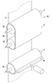
도 1은 본 실시예에 따른 용융 아연 도금 장치를 도시한 개략적인 도면이다.
도 2는 본 실시예에 따른 용융 아연 도금 장치의 나이프 구조를 도시한 개략적인 도면이다.
도 3은 본 실시예에 따른 용융 아연 도금 장치의 나이프에 대한 또다른 실시예를 도시한 개략적인 도면이다.
도 4는 본 실시예에 따른 나이프의 강판에 대한 접촉하중 제어 구조를 도시한 개략적인 도면이다.
도 5는 본 실시예에 따른 나이프의 팁부 구조 및 강판에 대한 배치 구조의 다양한 실시예를 도시한 개략적인 도면이다.
도 6은 본 실시예에 따른 용융 아연 도금 장치의 칠롤의 구조를 도시한 개략적인 도면이다.
도 7 내지 도 8은 본 실시예에 따른 용유 아연 도금 장치의 냉각부 구조를 도시한 개략적인 도면이다.
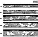
도 9와 도 10은 본 실시예에 따라 제조된 도금 강판의 표면 도금층 조직을 종래와 비교하여 나타낸 전자현미경 사진이다.
도 11은 비교예에 대해 냉각속도를 높인 경우의 도금층 단면 조직을 나타낸 전자현미경 사진이다.
도 12는 본 실시예에 따라 제조된 도금 강판의 도금층 특성을 종래와 비교하여 나타낸 도표이다.
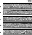
도 13은 본 실시예에 따른 도 12의 비교예들과 실시예들에 대한 도금층 결정 구조 변화를 X-ray 회절 시험기를 이용하여 나타낸 도면이다.
도 14와 도 15는 본 실시예에 따른 도 11의 비교예들과 실시예들에 대한 도금층 단면 조직을 나타낸 전자현미경 사진이다.
도 16은 본 실시예에 따른 도금 강판에 대한 내식성 실험 결과를 종래와 비교하여 나타낸 도면이다.
도 17은 본 실시예에 따라 도금층 표면에 패턴이 형성된 도금 강판을 도시한 것이다.1 is a schematic view showing a hot-dip galvanizing apparatus according to the present embodiment.
2 is a schematic view showing the knife structure of the hot dip galvanizing apparatus according to the present embodiment.
3 is a schematic view showing still another embodiment of the knife of the hot dip galvanizing apparatus according to the present embodiment.
4 is a schematic view showing a contact load control structure for a steel plate of a knife according to the present embodiment.
5 is a schematic view showing various embodiments of the tip structure of the knife and the arrangement structure of the steel plate according to the present embodiment.
6 is a schematic view showing the structure of the chill roll of the hot-dip galvanizing apparatus according to the present embodiment.
Figs. 7 to 8 are schematic views showing the structure of the cooling section of the liquefied zinc plating apparatus according to the present embodiment.
9 and 10 are electron micrographs showing the surface plating layer structure of the coated steel sheet manufactured according to the present embodiment in comparison with the prior art.
11 is an electron micrograph showing the cross-sectional structure of the plating layer when the cooling rate is increased for the comparative example.
12 is a chart showing the plating layer characteristics of the coated steel sheet produced according to the present embodiment in comparison with the prior art.
FIG. 13 is a diagram showing the change in the crystal structure of the plating layer with respect to the comparative examples and embodiments of FIG. 12 according to the present embodiment, using an X-ray diffraction tester.
FIGS. 14 and 15 are electron micrographs showing cross-sectional structures of the plating layer for the comparative examples and embodiments of FIG. 11 according to the present embodiment.
16 is a graph showing corrosion resistance test results of a plated steel sheet according to the present embodiment in comparison with conventional ones.
17 shows a plated steel sheet having a pattern formed on the surface of the plating layer according to this embodiment.
이하, 첨부한 도면을 참조하여, 본 발명이 속하는 기술분야에서 통상의 지식을 가진 자가 용이하게 실시할 수 있도록 본 발명의 실시예를 설명한다. 본 발명이 속하는 기술분야에서 통상의 지식을 가진 자가 용이하게 이해할 수 있는 바와 같이, 후술하는 실시예는 본 발명의 개념과 범위를 벗어나지 않는 한도 내에서 다양한 형태로 변형될 수 있으며 여기에서 설명하는 실시예에 한정되지 않는다.Hereinafter, embodiments of the present invention will be described with reference to the accompanying drawings so that those skilled in the art can easily carry out the present invention. It will be apparent to those skilled in the art that the embodiments described below may be modified in various ways without departing from the spirit and scope of the invention. But is not limited to the example.
도면들은 개략적이고 축적에 맞게 도시되지 않았다는 것을 일러둔다. 도면에 있는 부분들의 상대적인 치수 및 비율은 도면에서의 명확성 및 편의를 위해 그 크기에 있어 과장되거나 감소되어 도시되었으며 임의의 치수는 단지 예시적인 것이지 한정적인 것은 아니다.The drawings are schematic and illustrate that they are not drawn to scale. The relative dimensions and ratios of the parts in the figures are shown exaggerated or reduced in size for clarity and convenience in the figures, and any dimensions are merely illustrative and not restrictive.
[도금 강판 제조장치][Plated steel sheet manufacturing apparatus]
이하, 본 실시예에 따른 도금 강판을 제조하기 위한 제조장치를 설명하면 다음과 같다.Hereinafter, a manufacturing apparatus for manufacturing the coated steel sheet according to the present embodiment will be described.
본 실시예는 도금 장치로 강판 표면에 아연계 금속이나 금속 합금을 을 도금하는 용융 아연 도금 장치를 예로서 설명한다. 본 도금 장치는 아연계 금속이나 금속 합금의 도금에 한정되지 않으며, 다양한 금속에 대한 용융 도금 장치에 모두 적용가능하다.The present embodiment describes a hot-dip galvanizing apparatus for plating a zinc-based metal or a metal alloy on the surface of a steel sheet with a plating apparatus as an example. The present plating apparatus is not limited to the plating of a zinc-based metal or a metal alloy, and is applicable to a hot-dip coating apparatus for various metals.
도 1은 본 실시예에 따른 용융 아연 도금 장치를 개략적으로 도시하고 있다.Fig. 1 schematically shows a hot-dip galvanizing apparatus according to the present embodiment.
도 1에 도시된 바와 같이, 본 실시예의 도금 장치는 강판(P)을 용융 도금하는 도금 욕조(10), 강판 진행방향을 따라 상기 도금 욕조(10) 후단에서 강판의 일면 또는 양면에 배치되어 강판의 도금 부착량을 제어하는 와이핑부, 및 강판 진행방향을 따라 상기 와이핑부 후단에서 강판의 일면 또는 양면에 배치되어 강판을 냉각시키기 위한 냉각부를 포함한다.1, the plating apparatus according to the present embodiment includes a
도금 욕조(10)로 안내된 강판(P)은 도금 욕조(10) 내에 배치된 싱크롤(sink roll)(12)을 지나면서 용융 금속에 담겨져 용융 도금 공정이 진행된다. 강판(P)은 싱크롤(12)에 의해 진행 방향이 전환되어 도금 욕조(10) 상부로 이동하게된다. 도금 욕조(10) 내의 용융 금속에 의해 표면이 도금된 강판(P)은 도금 욕조(10) 상부로 인출된다. 강판은 진행방향을 따라 차례로 배치된 와이핑부 및 냉각부를 거쳐 도금 강판으로 제조된다. 냉각부를 거쳐 급냉된 강판은 텐션롤(14)을 거쳐 공정으로 진행된다.The steel sheet P guided to the
본 실시예에서, 상기 와이핑부는 강판 표면에 부착된 도금층에 직접 접촉하여 도금 부착량을 조절하는 구조로 되어 있다.In this embodiment, the wiping portion is in direct contact with the plating layer adhered to the surface of the steel sheet to adjust the plating deposition amount.
이를 위해, 상기 와이핑부는 강판(P) 표면의 도금층에 접촉하여 도금 부착량을 제어하는 나이프(20), 및 상기 나이프(20)로 액체 질소나 액체 헬륨을 포함하는 극저온 액체를 공급하여 나이프(20)를 냉각하는 냉매공급부(50)를 포함할 수 있다.The wiping portion is provided with a
나이프(20)를 도금층에 직접 접촉함으로써, 도금욕면의 산화물 혼입을 방지하고 보다 용이하게 강판의 도금 부착량을 제어할 수 있다. 상기 냉매공급부(50)는 나이프(20)를 극저온 액체로 냉각시킴으로써, 나이프(20)의 온도를 낮춰 나이프(20)가 고온의 도금층에 직접 접촉하는 상태에서도 도금 용액이 나이프(20)에 융착되는 것을 방지할 수 있게 된다.By directly contacting the
또한, 본 실시예에서 상기 냉각부는 강판 표면의 도금층에 직접 접촉하여 강판을 냉각하는 구조로 되어 있다. Further, in this embodiment, the cooling section has a structure in which the steel plate is cooled by directly contacting the plating layer on the surface of the steel plate.
이를 위해, 상기 냉각부는 강판 표면의 도금층에 밀착하여 도금층을 냉각하는 적어도 하나 이상의 냉각체(60), 및 상기 냉각체(60)로 액체 질소나 액체 헬륨을 포함하는 극저온 액체를 공급하여 냉각체(60)를 냉각하는 냉매공급부(50)를 포함할 수 있다.For this purpose, the cooling section includes at least one cooling
냉각체(60)를 도금층에 직접 접촉하여 강판의 도금층을 냉각시킴으로써, 냉각 능력을 극대화하여 보다 신속하게 강판 도금층을 급냉시킬 수 있게 된다. 상기 냉각부는 냉각체(60)를 극저온 액체로 냉각시킴으로써, 냉각체(60)의 온도를 낮춰 냉각체(60)가 고온의 도금층에 직접 접촉하는 상태에서도 도금 용액이 냉각체(60)에 융착되는 것을 방지할 수 있게 된다.By directly contacting the cooling
상기 냉매공급부(50)는 나이프(20) 또는 냉각체(60)로 극저온 액체를 공급하기 위한 것으로, 예를 들어 극저온 액체가 수용된 탱크, 극저온 액체가 이송되는 공급라인, 공급라인 상에 설치되는 공급펌프를 포함할 수 있다. 상기 냉매공급부(50)는 극저온 액체를 공급할 수 있는 구조면 모두 적용가능하며 다양하게 변형될 수 있다.The
상기 냉매공급부(50)에서 사용되는 극저온 액체는 액체 질소, 액체 헬륨 이외에 액체 아르곤 등 다양한 액체가 사용될 수 있다. 액체 질소를 사용하는 경우 보다 경제성을 높일 수 있다.As the cryogenic liquid used in the
이와 같이, 극저온 액체를 사용하여 냉각된 나이프(20)와 냉각체(60)가 강판(P)에 직접 접촉되어 강판의 도금량을 제어하고 급냉시킴으로써, 본 실시예를 통해 도금 강판의 도금 부착량을 정밀 제어할 수 있고, 도금 강판의 냉각속도를 20℃/sec 이상으로 높일 수 있게 된다. 따라서, 강판 냉각을 위한 설비 라인 길이를 획기적으로 단축하고 제품 생산 속도를 높일 수 있게 된다.As described above, the
상기 냉매공급부(50)를 통해 나이프(20) 또는 냉각체(60)로 공급된 극저온 액체는 나이프(20) 또는 냉각체(60)를 지나면서 도금층과 열교환되어 기체화될 수 있다. 나이프(20) 또는 냉각체(60)에서 배출되는 가스는 적절한 여과 장치를 거쳐 제철 공정의 열처리로(furnace) 내 환원가스 또는 냉각공정에서의 비산화성 분위기 유지를 위한 가스로 사용하여 재활용될 수 있다.The cryogenic liquid supplied to the
도 2는 본 실시예에 따른 나이프의 구체적인 구조를 예시하고 있다.Fig. 2 illustrates a specific structure of the knife according to the present embodiment.
본 실시예에서, 상기 나이프(20)는 강판의 양면에 대향 배치되어 강판(P) 양면에 대해 도금액의 부착량을 조절한다. 강판(P) 양면에 배치되는 나이프(20)는 동일한 구조로 이루어지며, 이하 설명은 강판의 일면에 대한 나이프(20)만을 예로서 설명한다.In the present embodiment, the
도 2에 도시된 바와 같이, 상기 나이프(20)는 강판(P) 폭방향으로 연장되고 내부에는 극저온 액체가 순한되는 바디(22), 및 상기 바디(22) 선단에 설치되고 강판의 도금층에 접하는 팁부(24)를 포함하여, 강판 표면의 도금 부착량을 1차적으로 제어하는 구조일 수 있다.2, the
상기 바디(22)와 상기 팁부(24)는 액체 질소 사용에 따른 극저온 환경에서 장시간 안정적으로 사용 가능하도록, 극저온 내구성이 우수한 금속(metal), 세라믹(ceramic) 또는 세라믹 코팅된 금속재 등으로 제조될 수 있다.The
상기 바디(22)는 내부에 극저온 액체가 지나가도록 유로(26)가 형성된다. 상기 바디(22)에 연결된 냉매공급부(50)는 유로(26)를 통해 극저온 액체를 순환 공급한다. 상기 유로(26)는 바디(22)의 선단에 설치된 팁부(24)를 충분히 냉각할 수 있도록 팁부(24)가 위치한 선단까지 연장 형성되어, 팁부(24)에 극저온 액체가 접촉될 수 있도록 한다. The body (22) is formed with a flow path (26) so that a cryogenic liquid passes through the body (22). The
본 실시예에서, 상기 팁부(24)는 바디(22)에 대해 착탈가능하게 설치될 수 있다. In this embodiment, the
상기 팁부(24)는 고온의 도금층과 계속 접촉되어 마모된다. 이에, 소모성인 팁부(24)를 교체가능한 부품화하여 마모시 바디(22)에서 팁부(24)만을 교체하여 나이프(20)를 계속 사용할 수 있다. 상기 팁부(24)는 보다 정밀한 도금 부착량 제어를 위해 선단으로 갈수록 뾰족하게 형성된 구조일 수 있다. The
상기 바디(22)로 공급된 극저온 액체는 유로(26)를 따라 순환되면서 팁부(24)를 냉각시켜, 팁부(24)를 저온 상태를 유지시키게 된다. 이에, 팁부(24)는 도금층에 접한 상태에서 도금용액이 팁부(24)에 부착되는 것을 방지하면서, 일차적으로 도금 부착층을 보다 정확하게 제어할 수 있게 된다.The cryogenic liquid supplied to the
도 3은 나이프의 또다른 실시예를 예시하고 있다. 도 3의 실시예에 따른 나이프는 팁부 이상시 바로 교환하여 사용할 수 있도록 복수개의 팁부를 구비한 구조로 되어 있다.Figure 3 illustrates another embodiment of a knife. The knife according to the embodiment of FIG. 3 has a structure in which a plurality of tips are provided so that the knife can be exchanged and used immediately in the event of a tip failure.
이를 위해, 본 실시예의 나이프(21)는 강판 폭방향으로 연장되고 회전가능하게 설치되며 내부에는 극저온 액체가 순환되는 회전체(23)와, 상기 회전체(23) 외주면에 원주방향을 따라 간격을 두고 설치되고 강판(P) 표면의 도금층에 접하여 도금 부착량을 제어하는 팁부(24), 및 상기 회전체(23)에 연결되어 회전체(23)를 회전시켜 일측 팁부(24)를 강판 표면을 향하여 배치시키는 회전구동부를 포함할 수 있다.To this end, the
이에, 팁부(24) 마모와 같은 이상 발생시 회전체(23)를 회전시켜 사용중인 팁부(24)를 강판에서 이격시키고 대기중에 있는 다른 팁부(24)를 강판쪽으로 이동시킴으로써, 바로 팁부(24)를 교체하여 사용할 수 있게 된다. 상기 팁부(24)는 도 3에 도시된 바와 같이 4개가 회전체(23) 외주면을 따라 90도 각도로 배치될 수 있다. 이에 회전체(23)가 90도 각도로 회전되어 각 팁부(24)를 강판 표면쪽으로 이동시킬 수 있게 된다. 상기 팁부(24)의 설치 개수는 다양하게 변형 가능하다. Accordingly, when an abnormality such as abrasion of the
본 실시예에서, 상기 회전체(23)는 원통형태로 이루어질 수 있다. 상기 회전체(23)는 원통형태에 한정되지 않으며, 예를 들어 회전축의 외주면을 따라 위에서 언급한 바디(22)가 각도를 두고 연속적으로 배치된 구조일 수 있다. 상기 회전체(23)의 양 선단은 설비 상에 별도의 지지대(도시되지 않음)에 회전가능하게 지지될 수 있다.In the present embodiment, the rotating
상기 회전체(23) 역시 액체 질소 사용에 따른 극저온 환경에서 장시간 안정적으로 사용 가능하도록, 극저온 내구성이 우수한 금속(metal), 세라믹(ceramic) 또는 세라믹 코팅된 금속재 등으로 제조될 수 있다.The rotating
상기 회전체(23)는 내부에 극저온 액체가 지나가도록 유로(도시되지 않음)가 형성된다. 회전체(23) 내부에 형성되는 유로는 회전체(23)의 회전축 양 선단을 통해 냉매공급부(50)와 연결될 수 있다. 냉매공급부(50)로부터 공급된 극저온 액체는 상기 회전체(23)의 선단을 통해 회전체(23) 내부의 유로로 순환 공급된다. 상기 유로는 회전체(23) 외주면에 설치된 팁부(24)를 충분히 냉각할 수 있도록 팁부(24)가 위치한 표면으로 연장 형성되어, 팁부(24)에 극저온 액체가 접촉될 수 있도록 한다. A flow path (not shown) is formed in the
상기 회전체(23)의 표면에 축방향을 따라 팁부(24)가 설치된다. 상기 팁부(24)는 회전체(23) 표면에 착탈가능하게 설치될 수 있다.A tip portion (24) is provided on the surface of the rotating body (23) along the axial direction. The
상기 회전구동부는 회전체(23)를 설정된 각도만큼 회전시키는 구조면 모두 적용가능하다. 도 3에 도시된 바와 같이 예를 들어, 상기 회전동부는 회전체(23)와 구동벨트(25)로 연결되어 동력을 전달하는 스텝모터(27)를 포함할 수 있다. 이에, 스텝모터(27)가 일정량 회전구동되면 구동벨트(25)를 통해 회전체(23)에 동력이 전달되어 회전체(23)가 팁부(24)의 배치 간격만큼 회전된다. 회전체(23)의 회전에 따라 회전체(23) 표면에 설치되어 대기 중에 있던 새 팁부(24)가 강판 쪽으로 이동하여 강판 표면의 도금층에 접촉된다. 그리고 회전체(23) 회전에 따라 마모되거나 이상이 있는 팁부(24)는 강판 표면에서 외측으로 이격되어 대기 위치로 이동된다. 마모된 팁부(24)는 대기 위치에서 교체 또는 표면 연마 작업을 통해 처리된다.The rotation driving unit is applicable to all of the structures that rotate the
이와 같이, 본 실시예의 경우 회전체(23)를 소정 각도로 회전시키는 것으로 간단하게 팁부(24)를 교체함으로써, 팁부(24) 교체에 따른 시간을 줄이고 연속적으로 작업을 진행할 수 있게 된다.As described above, in the present embodiment, by simply rotating the
본 실시예에서, 상기 나이프(20,21)는 내부로 극저온 액체를 순환시켜 팁부(24)를 -250 내지 5℃로 냉각시킬 수 있다. 상기 팁부(24)의 온도가 5℃ 보다 높게 되면 고온의 도금용액이 팁부(24)에 부착되는 문제가 발생된다. 상기 팁부(24)의 온도가 -250℃ 보다 낮은 경우에는 상기 팁부(24)의 저온취성 파괴 문제가 발생된다. In the present embodiment, the
또한, 상기 나이프(20,21)는 강판에 대해 이동되어 팁부(24)에 의한 도금 부착량을 정밀하게 조절하게 된다. In addition, the
도 4에 도시된 바와 같이, 상기 나이프(20)에 의한 도금 부착량의 정밀 제어를 위해, 상기 와이핑부는 상기 나이프(20)에 구비되어 강판(P)에 대한 팁부(24)의 접촉 하중을 검출하는 로드센서(30), 및 상기 로드센서(30)의 검출신호에 따라 강판에 대해 나이프(20)를 이동하여 강판에 대한 팁부(24)의 가압력을 제어하는 제어부(32)를 더 포함할 수 있다.4, the wiping portion is provided on the
상기 나이프(20)가 강판의 도금층으로 더 접근하거나 도금층에서 외측으로 이격됨으로써, 팁부(24)와 강판(P)과의 간격이 달라져 강판의 도금 부착량이 조절된다.The distance between the
팁부(24)와 강판(P) 사이의 간격은 로드센서(30)를 통해 검출된 팁부의 접촉 하중을 통해 확인할 수 있다. 팁부(24)와 강판(P) 사이의 간격이 좁아지면 팁부(24)가 강판의 도금층에 깊이 들어가 도금 용액과의 접촉량이 많아지면서 접촉하중이 커지게 되며, 반대로 팁부(24)가 강판(P)에서 이격되면 도금 용액과의 접촉량이 줄면서 접촉하중이 작아지게 된다.The distance between the
상기 제어부(32)는 로드센서(30)의 검출값을 연산하여 1차적으로 설정된 도금 부착량에 맞춰 강판(P)에 대해 나이프(20)를 이동시켜 도금 부착량을 제어한다. The
강판에 대한 상기 나이프(20)의 이동은 예를 들어, 나이프(20)에 결합된 구동실린더 등의 구동부(34)를 통해 이루어질 수 있다. 상기 구동부(34)는 구동실린더나 모터 등 다양한 동력원이 이용될 수 있으며, 나이프(20)를 강판에 대해 직선 이동시킬 수 있는 구조면 모두 적용가능하다.The movement of the
또한, 상기 제어부(32)는 로드센서(30)의 측정값 변화를 감지하여, 장치 이상 유무를 확인할 수 있다. 장치 이상 판별시 나이프(20)에서 팁부(24)를 교체하는 등 필요한 조치를 바로 취할 수 있게 된다.In addition, the
도 5는 강판에 대한 나이프의 팁부 형태 및 강판에 대한 팁부의 배치 구조를 예시하고 있다.Fig. 5 illustrates the tip shape of the knife with respect to the steel sheet and the arrangement structure of the tip portion with respect to the steel sheet.
본 실시예에서, 상기 나이프(20,21)에 설치되는 팁부(24)는 직선 형태이거나, 중간이 꺽여져 V자 형태를 이루는 구조 등 다양한 구조로 형성될 수 있다. 상기 팁부(24)가 설치되는 나이프의 바디(22) 또는 회전체(23) 역시 팁부(24)의 형태와 동일한 구조로 이루어질 수 있다. 예를 들어, 상기 팁부(24)가 V자 형태로 이루어진 경우 팁부(24)가 설치되는 나이프(20)의 바디(22) 역시 선단부는 팁부(24)와 같은 형태인 V 자 형태로 이루어질 수 있다.In this embodiment, the
도 5에 도시된 바와 같이, 상기 팁부(24)는 강판(P)에 폭방향에 대해 평행하게 배치될 수 있다. 또한, 상기 팁부(24)는 강판의 폭방향에 대해 경사지게 배치될 수 있다.As shown in FIG. 5, the
또한, 상기 팁부(24)가 V자 형태로 꺽여진 구조의 경우, 꺽여진 부분이 강판의 이동방향을 향하거나 강판의 이동방향에 반대방향을 향하도록 역V 자 형태 또는 V자 형태로 배치될 수 있다.Further, in the case of the structure in which the
강판(P)에 대해 도금층과 접하는 팁부(24)의 배치를 다양하게 함으로써, 도금층과 팁부(24)와의 접촉 하중을 줄여 보다 원활하게 도금층의 부착량을 조절할 수 있게 된다.By varying the arrangement of the
도 1과 도 6에 도시된 바와 같이, 상기 와이핑부는 강판 진행방향을 따라 상기 나이프(20) 후단에 배치되어 강판의 도금 부착량을 보다 정밀하게 제어하고 강판의 도금층을 급냉시키는 칠롤(40)을 더 포함할 수 있다.As shown in FIGS. 1 and 6, the wiping portion is disposed at the rear end of the
상기 칠롤(chill roll)(40)은 강판의 폭방향으로 배치되고 도금층에 가압 밀착되는 롤 구조물이다. 상기 칠롤(40)의 양 선단은 설비 상에 별도의 지지대(도시되지 않음)에 회전가능하게 지지될 수 있다. 상기 칠롤(40)은 자유롭게 회전가능한 구조로 강판의 이동에 따라 같이 회전되거나, 별도의 구동원에 연결되어 설정된 속도로 회전되는 구조일 수 있다. The
본 실시예에서, 상기 칠롤(40)은 표면조도가 평균 0.1 내지 3㎛ 일 수 있다.In the present embodiment, the
상기 칠롤(40)의 표면조도가 3㎛보다 높게 되면 열위한 표면 품질로 인한 불균일한 후처리 문제가 발생된다. 상기 칠롤(40)의 표면조도가 0.1㎛ 보다 낮은 경우에는 화성처리와 같은 후처리 특성이 저하되는 문제가 발생된다.If the surface roughness of the chill roll (40) is higher than 3 탆, uneven post-treatment problems arise due to surface quality for heat. When the surface roughness of the
상기 칠롤(40)은 내부로 극저온 액체가 순환되어 저온으로 냉각되는 구조로 되어 있다. 상기 칠롤(40)은 액체 질소 사용에 따른 극저온 환경에서 장시간 안정적으로 사용 가능하도록, 극저온 내구성이 우수한 금속(metal), 세라믹(ceramic) 또는 세라믹 코팅된 금속재 등으로 제조될 수 있다.The
도 6에 도시된 바와 같이, 상기 칠롤(40) 내부에는 극저온 액체가 지나가도록 유로가 형성된다. 칠롤(40) 내부에 형성되는 유로는 칠롤(40)의 회전축 양 선단을 통해 냉매공급부(도 1의 50 참조)와 연결될 수 있다. 냉매공급부(50)로부터 공급된 극저온 액체는 상기 칠롤(40)의 선단을 통해 칠롤(40) 내부의 유로로 순환 공급된다. 칠롤(40) 내부로 공급된 극저온 액체에 의해 칠롤(40) 표면은 저온의 냉각 상태를 유지한다. 이에, 칠롤(40)은 강판(P)의 도금층에 접한 상태에서 도금용액이 칠롤(40) 표면에 부착되는 것을 방지하고, 도금층을 급속 냉각시킬 수 있게 된다. As shown in FIG. 6, a channel is formed in the
따라서, 상기 칠롤(40)은 강판(P) 표면의 도금층에 밀착하여 일차적으로 나이프(20)를 거친 강판(P)의 도금 부착량을 이차적으로 정밀 제어한다. 더불어 상기 칠롤(40)은 도금층에 접하여 직접적인 열교환을 통해 도금층을 급속 냉각시시킬 수 있게 된다.Therefore, the
본 실시예에서, 상기 칠롤(40)은 내부로 극저온 액체를 순환시켜 온도를 -250 내지 5℃로 냉각시킬 수 있다. 상기 칠롤(40)의 온도가 5℃ 보다 높게 되면 도금강판의 냉각성능 및 표면품질 개선 효율이 저하되는 문제가 발생된다. 상기 칠롤(40)의 온도가 -250℃ 보다 낮은 경우에는 상기 칠롤(40)의 저온취성 파괴 문제가 발생된다. In the present embodiment, the
이와 같이, 본 실시예의 도금 장치는 강판 도금층에 접하는 저온의 나이프(20)와 칠롤(40)을 통해 도금 부착량을 보다 정밀하게 제어할 수 있게 된다. 또한, 저온으로 냉각된 칠롤(40)이 도금층을 가압하여 급속 냉각시킴으로서 도금층의 조직을 미세화시키며 폭방향으로의 도금 부착량 편차를 효과적으로 줄이게 된다.Thus, in the plating apparatus of this embodiment, it is possible to more precisely control the plating deposition amount through the
칠롤(40)이 도금층에 접촉하여 보다 빠른 시간 내에 도금 용액을 응고시킴으로써, 상기 도금 장치는 강판을 20℃/sec 의 냉각 속도로 급냉시킬 수 있게 된다. 뿐만 아니라, 상기 칠롤(40)은 소정의 압력 하에 도금층을 가압하면서 냉각이 진행되므로 난도금성 강종에 대해서도 도금성능을 개선할 수 있게 된다. The
또한, 본 실시예의 경우 도금 욕조(10)의 싱크롤(12)과 칠롤(40)이 연동하여 강판(P)을 지지하고 있는 상태가 되어 강판이 접촉식 나이프(20)를 지나는 과정에서 폭방향으로 굽어지는 반곡 현상이 전혀 발생되지 않는다. 즉, 강판 이동방향을 따라 나이프(20)의 전단과 후단에서 강판은 각각 싱크롤(12)과 칠롤(40)을 지나게 된다. 이에 강판(P)은 싱크롤(12)과 칠롤(40)에 의해 평평하게 펴진 상태로 반곡 현상의 발생없이 나이프(20)를 지나게 된다. In the present embodiment, the
강판이 반곡되는 경우, 폭방향으로의 도금 부착량 편차가 발생되고 측면 과도금으로 인한 빗살 무늬 결함 등의 도금 표면 결함이 발생된다. 종래 구조의 경우 이러한 강판 반곡 현상에 따른 도금 표면 결함이 빈번하게 발생되나, 본 실시예의 경우 강판의 반곡 발생을 방지함으로써, 폭방향의 도금 부착량 및 도금층 조직 편차가 거의 없는 도금 강판의 제조가 가능하다. When the steel sheet is curved, a variation in the plating deposition amount in the width direction is generated, and plating surface defects such as a comb-like defect due to lateral over-plating occur. In the case of the conventional structure, plating surface defects are frequently caused by the bending of the steel sheet, but in the case of this embodiment, the occurrence of bending of the steel sheet is prevented so that it is possible to manufacture a coated steel sheet having almost no coating amount .
본 실시예의 와이핑부는 상기 칠롤(40)에 의한 도금 부착량의 정밀 제어를 위해, 나이프와 마찬가지로 상기 칠롤(40)에 구비되어 강판에 대한 칠롤(40)의 접촉 하중을 검출하는 로드센서(30), 및 상기 로드센서의 검출신호에 따라 구동부(34)를 작동하여 강판에 대해 칠롤(40)을 이동하여 강판에 대한 칠롤(40)의 가압력을 제어하는 제어부(32)를 더 포함할 수 있다.The wiping unit of the present embodiment is provided with a
상기 칠롤(40)이 강판(P)의 도금층으로 접근하거나 도금층에서 외측으로 이격됨으로써, 칠롤(40)과 강판과의 간격이 달라져 강판의 도금 부착량이 정밀하게 조절된다.The distance between the
칠롤(40)에 대한 로드센서와 제어부의 구조는 위에서 언급한 나이프(20)에 대한 로드센서(30)와 제어부(32) 및 구동부(34)의 구조와 동일하므로 동일한 부호를 사용하고, 그 구조와 작용은 나이프(20)에 대한 로드센서(30)와 제어부(32)의 설명을 참조하며, 이하 상세한 설명은 생략한다. 이에, 상기 제어부(32)는 로드센서(30)의 검출값을 연산하여 강판에 대해 칠롤(40)을 이동시켜 도금층을 가압함으로써, 도금 부착량을 보다 정밀하게 제어할 수 있다. 또한, 칠롤에 의해 도금층이 가압되면서 20℃/sec 이상의 냉각속도로 급냉됨으로써, 폭방향 도금 부착량 편차를 최소화하면서 보다 미세한 조직의 도금층을 얻을 수 있게 된다.The structure of the load sensor and the control unit with respect to the
또한, 상기 와이핑부는 칠롤(40) 표면이 오염되었을 경우에 대비하여 칠롤(40) 표면의 오염물을 제거하는 구조로 되어 있다. 이를 위해, 도 7에 도시된 바와 같이, 상기 와이핑부는 칠롤(40)에 접하여 칠롤(40) 표면에 부착된 오염물을 제거하기 위한 스크레퍼(44)를 더 포함할 수 있다. 상기 스크레퍼(44)는 칠롤(40)의 축방향으로 연장되어 칠롤(40) 표면에 접촉되도록 설치될 수 있다. 이에, 상기 칠롤(40)이 회전되면서 칠롤(40) 표면에 부착된 오염물이 스크레퍼(44)에 걸려 칠롤(40) 표면에서 제거된다.The wiping unit is configured to remove contaminants on the surface of the
상기 와이핑부를 거쳐 도금 부착량이 정밀 조절되고 급냉이 이루어진 강판은 와이핑부 후단에 배치된 냉각부를 거치면서 설정 온도 이하로 급속 냉각된다. 또한, 본 실시예에서 강판은 냉각부를 거치면서 도금층 두께가 정밀하게 제어된다. The steel plate precisely adjusted in plating amount through the wiping portion and quenched is rapidly cooled to a set temperature or lower while passing through a cooling portion disposed at the rear end of the wiping portion. Further, in this embodiment, the thickness of the plating layer is precisely controlled while passing through the cooling portion of the steel sheet.
도 7과 도 8은 본 실시예에 따른 냉각부의 구조를 예시하고 있다.7 and 8 illustrate the structure of the cooling section according to the present embodiment.
상기 냉각부는 강판 표면의 도금층에 밀착하여 도금층을 냉각하는 적어도 하나 이상의 냉각체(60), 및 상기 냉각체(60)로 액체 질소나 액체 헬륨을 포함하는 극저온 액체를 공급하여 냉각체(60)를 냉각하는 냉매공급부(50)를 포함할 수 있다.The cooling section includes at least one cooling
본 실시예에서, 상기 냉각체(60)는 강판 폭방향으로 연장되고 내부에는 극저온 액체가 순환되며 강판(P) 표면의 도금층에 가압되어 냉기를 가하는 냉각롤(62)을 포함할 수 있다. 상기 냉각롤(62)은 복수개가 강판의 진행방향을 따라 간격을 두고 다단으로 배치된 구조일 수 있다.In the present embodiment, the cooling
상기 냉각롤(62)은 상기 칠롤(40)과 마찬가지로 강판의 폭방향으로 배치되는 롤 구조물이다. 상기 냉각롤(62)의 양 선단은 설비 상에 별도의 지지대(도시되지 않음)에 회전가능하게 지지될 수 있다. 상기 냉각롤(62)은 자유롭게 회전가능한 구조로 강판의 이동에 따라 같이 회전되거나, 별도의 구동원에 연결되어 설정된 속도로 회전되는 구조일 수 있다. The
상기 냉각롤(62)은 내부로 극저온 액체가 순환되어 저온으로 냉각되는 구조로 되어 있다. The
칠롤(40)과 마찬가지로 상기 냉각롤(62) 내부에는 극저온 액체가 지나가도록 유로(64)가 형성된다. 냉각롤(62) 내부에 형성되는 유로(64)는 냉각롤(62)의 회전축 양 선단을 통해 냉매공급부(도 1의 50 참조)와 연결될 수 있다. 냉매공급부(50)로부터 공급된 극저온 액체는 상기 냉각롤(62)의 선단을 통해 냉각롤(62) 내부의 유로(64)로 순환 공급된다. 냉각롤(62) 내부로 공급된 극저온 액체에 의해 냉각롤(62) 표면은 저온의 냉각 상태를 유지한다.Like the
또한, 상기 냉각체(60)는 적어도 두 개의 냉각롤(62) 사이에 감겨져 설치되고 강판(P) 표면의 도금층에 가압 밀착하여 냉기를 가하는 냉각벨트(66)를 더 포함할 수 있다. 이러한 구조의 경우 냉각롤(62)이 아닌 냉각벨트(66)가 강판의 도금층에 직접 접하게 된다.The cooling
상기 냉각롤(62)과 상기 냉각벨트(66)는 액체 질소 사용에 따른 극저온 환경에서 장시간 안정적으로 사용 가능하도록, 극저온 내구성이 우수한 스테인레스 등의 금속(metal), 세라믹(ceramic) 또는 세라믹 코팅된 금속재 등으로 제조될 수 있다.The
본 실시예에서, 상기 강판 표면에 접하는 냉각롤(62) 또는 냉각벨트(66)는 표면조도가 평균 0.1 내지 3㎛ 일 수 있다. 상기 냉각롤(62) 또는 냉각벨트(66)의 표면조도가 3㎛보다 높게 되면 열위한 표면 품질로 인한 불균일한 후처리 문제가 발생되며, 표면조도가 0.1㎛ 보다 낮은 경우에는 화성처리와 같은 후처리 특성이 저하되는 문제가 발생된다.In this embodiment, the
본 실시예에서, 두 개의 냉각롤(62)에 냉각벨트(66)가 감겨져 하나의 냉각체(60)를 이루며, 이러한 냉각체(60) 하나 또는 복수개가 강판의 진행방향을 따라 간격을 두고 배치된 구조로 되어 있다. 각 냉각체(60)의 설치 간격이나 개수 등은 설비나 공정 조건에 따라 다양하게 변형 가능하다. In this embodiment, the cooling
각 냉각체(60)는 동일한 구조로 이루어질 수 있으며, 이하 일측 냉각체에 대한 구조를 예로서 설명한다.Each cooling
이격된 두 개의 냉각롤(62) 사이에 냉각벨트(66)가 감겨져 설치되고, 냉각벨트(66)는 강판 표면의 도금층에 면접촉된다. 상기 냉각벨트(66)는 예를 들어, 강판에 접한 상태에서 냉각롤(62)의 회전구동에 의해 강판의 이동 속도에 맞춰 회전될 수 있다. 강판의 이동 속도에 맞춰 냉각벨트(66)가 회전됨으로써, 강판과 냉각벨트(66) 사이의 마찰을 최소화하고 마찰에 의한 도금층 손상을 방지할 수 있다.A cooling
냉각롤(62)은 외측의 구비된 냉각벨트(66)를 저온으로 냉각시키게 된다. 냉각벨트(66)는 냉각롤(62)에 의해 저온으로 냉각된 상태로 도금층에 면접촉하고 있어, 도금층을 급속 냉각시킬 수 있게 된다. 즉, 상기 냉각벨트(66)는 두 개의 냉각롤(62) 사이에서 강판 표면의 도금층에 면접촉하고 있다. 이에, 강판의 도금층에 대한 냉각 면적은 냉각벨트(66)에 의한 접촉면적만큼 커지게 된다. 따라서, 본 실시예의 냉각부는 냉각벨트(66)를 통해 강판 도금층에 대한 냉각 면적을 늘려 냉각 속도를 높일 수 있게 된다.The
본 실시예에서, 상기 냉각롤(62)은 내부로 극저온 액체를 순환시켜 도금층과 접하는 냉각벨트(66)의 온도를 -250 내지 5℃로 냉각시킬 수 있다. 상기 냉각벨트(66)의 온도가 5℃ 보다 높게 되면 도금강판의 냉각성능 및 표면품질 개선 효율이 저하되는 문제가 발생된다. 상기 냉각벨트(66)의 온도가 -250℃ 보다 낮은 경우에는 상기 냉각벨트(66)의 저온취성 파괴 문제가 발생된다.In this embodiment, the
이와 같이, 냉각롤(62)에 설치된 냉각벨트(66)가 도금층에 접촉하여 보다 빠른 시간 내에 도금 용액을 응고시킴으로써, 본 실시예의 도금 장치는 냉각부를 통해 강판을 20℃/sec 의 냉각 속도로 250℃ 이하의 온도까지 급냉시킬 수 있게 된다.As described above, the cooling
상기 냉각부는 유닛을 구성하는 두 개의 냉각롤(62) 사이의 간격을 조절하여 냉각벨트(66)를 팽팽하게 긴장시킬 수 있다. 냉각벨트(66)가 긴장되어 팽팽하게 펼쳐짐에 따라 강판 표면의 도금층과 냉각벨트(66)의 접촉이 원활하게 이루어지고 도금층을 보다 고르게 냉각시킬 수 있게 된다. The cooling section can tighten the cooling
도 8에 도시된 바와 같이, 이를 위해 상기 냉각부는 냉각벨트(66)가 감겨진 두 개의 냉각롤(62) 사이에 냉각롤(62) 사이를 신축시키는 구동실린더(68)가 설치될 수 있다. 상기 구동실린더(68)는 제어부(32)의 신호에 따라 구동되어 냉각롤(62) 사이를 벌리게 된다. 냉각롤(62) 사이가 벌어짐에 따라 냉각벨트(66)가 팽팽하게 펼쳐지게 된다.As shown in Fig. 8, for this purpose, the cooling section may be provided with a
또한, 상기 냉각롤(62)은 강판의 도금층에 대한 가압력을 정밀하게 조절할 수 있다. 이를 위해, 상기 냉각롤(62)은 도시되지 않았으나, 칠롤(40)과 동일하게 로드센서와 제어부 및 구동부를 구비할 수 있다. 냉각롤의 가압력 조절 구조는 위에서 언급한 칠롤(40)에 대한 로드센서(30)와 제어부(32) 및 구동부(34)의 구조와 동일하므로, 그 구조와 작용에 대한 상세한 설명은 생략한다. 이에, 냉각롤은 강판에 설정된 압력으로 가압 밀착되어 강판의 도금층 두께를 정밀하게 제어하게 된다.In addition, the
상기 냉각롤(62)이 강판의 도금층으로 접근하거나 도금층에서 외측으로 이격됨으로써, 냉각롤(62)에 감겨진 냉각벨트(66)와 강판과의 간격이 달라져 강판의 도금층에 대한 가압력이 조절된다. 이와 같이, 상기 냉각부는 로드센서의 검출값을 연산하여 강판에 대해 냉각롤(62)을 이동시켜 냉각벨트(66)에 의한 도금층 가압력을 정밀하게 조절함으로써, 도금층 두께를 정밀하게 제어할 수 있게 된다.Since the
여기서, 상기 냉각롤(62)의 이동에 따른 냉각벨트(66)의 가압력은 강판의 이동방향을 따라 배치된 복수개의 냉각체(60) 각각에 대해 동일하거나 상이할 수 있다. 즉, 강판의 이동 방향을 따라 배치된 각 냉각체(60)는 동일한 가압력으로 강판에 밀착될 수 있다. 또는 상기 각 냉각체(60)는 강판의 이동방향을 따라 점차적으로 가압력을 높여 강판에 밀착될 수 있다. 따라서, 강판은 각 냉각체(60)를 지나면서 점차적으로 높은 가압력을 받아 도금층 두께를 점차적으로 줄일 수 있게 된다.Here, the pressing force of the cooling
이에, 상기 강판의 이동방향을 따라 상기 나이프(20)에서 냉각롤(62)로 가면서 점차적으로 강판의 도금층을 가압하여 도금층 두께를 보다 정밀하게 제어할 수 있게 된다.Accordingly, the thickness of the plating layer can be controlled more precisely by pressing the plating layer of the steel plate gradually from the
또한, 상기 냉각부는 소정의 압력 하에 도금층을 가압하면서 도금층을 급냉시킴으로써, 난도금성 강종에 대해서도 도금성능을 개선할 수 있게 된다. Further, by cooling the plating layer while pressurizing the plating layer under a predetermined pressure, the cooling section can improve the plating performance also against the difficult-to-handle steel species.
이와 같이, 본 실시예의 도금 장치는 극저온 액체에 의해 냉각된 냉각벨트를 도금층에 밀착시켜 냉각시킴으로써, 종래와 비교하여 도금층을 급속 냉각시킬 수 있게 된다. 도금 강판 냉각은 제품의 표면 품질에 직접적인 영향을 미친다. 만약 미응고 도금층이 오염된 가스 또는 설비 후단의 롤에 접촉되는 경우 직접적인 표면 결함 발생의 원인이 되기 때문에 도금층은 설비 후단으로 진입하기 전에 완전히 응고되어야 한다. 종래 구조의 경우 가스나 수냉방식을 이용함에 따라 열용량이 낮아 냉각능력이 떨어지고, 이에 도금강판을 일정 온도 이하로 냉각시켜 도금층을 완전히 응고시키기 위해서는 매우 긴 다단계의 냉각라인을 필요로 하였다. 따라서 종래에는 냉각 라인이 상당히 복잡하고 설비 규모가 방대하여 설비를 효과적으로 관리하기 어려워 표면 결함 발생이 빈번하였다. 특히, Zn 도금 용액에 Al, Mg가 다량 첨가된 합금도금 강판과 같이 도금층의 응고 시작 온도와 응고 완료 온도 차가 큰 경우에는 종래의 가스를 이용한 방식으로는 충분한 냉각효과를 얻기 어렵다. 이에, 도금층의 냉각이 제대로 이루어지지 못해, 강산화성 금속인 Al, Mg 함유 조대하고 취약한 도금층 조직이 생성되며, 이러한 영역에서 흑점, 흑변과 같은 도금층 표면 결함이 발생되고 도금층 크랙발생 및 내식성 저하의 문제를 유발하게 된다.Thus, in the plating apparatus of this embodiment, the cooling belt cooled by the cryogenic liquid is brought into close contact with the plating layer and cooled, whereby the plating layer can be rapidly cooled as compared with the conventional one. Plated steel plate cooling has a direct effect on the surface quality of the product. If the uncoated plated layer is contacted with a contaminated gas or a roll at the end of the equipment, it will cause direct surface defects and the plated layer must be completely solidified before entering the end of the installation. In the case of the conventional structure, since the heat capacity is low due to the use of the gas or the water-cooling method, the cooling capacity is lowered and a very long multi-stage cooling line is required to completely cool the plated steel sheet by cooling the plated steel sheet to a predetermined temperature or less. Therefore, conventionally, since the cooling line is considerably complicated and the facility scale is large, it is difficult to effectively manage the facilities, and surface defects are frequently generated. Particularly, when the solidification start temperature and the solidification completion temperature difference of the plating layer are large, such as the alloy-plated steel sheet in which a large amount of Al and Mg are added to the Zn plating solution, a sufficient cooling effect can not be obtained by the conventional method using gas. Thus, the plating layer is not sufficiently cooled, and a large and weak plating layer structure containing Al and Mg, which are strong oxidizing metals, is produced. In such a region, surface layer defects such as black spots and black spots are generated and cracking of the plating layer and deterioration of corrosion resistance .
이에 반해, 본 실시예의 경우, 강판의 도금층에 직접 냉각벨트(66)가 접촉하여 극저온 액체를 이용하여 도금층을 냉각시킴으로써, 냉각효율을 보다 높일 수 있게 된다. 이에, 도금층 냉각에 소요되는 시간을 크게 단축시킬 수 있게 된다. 따라서, 본 실시예에 따라 도금 강판의 냉각속도가 20℃/sec 이상으로 높아져 냉각부의 설비라인을 보다 줄일 수 있게 된다. 또한, 강판에 가스가 직접적으로 접촉하지 않아 표면 결함 발생을 최소화할 수 있고, 보다 작고 균일한 도금 조직을 얻어 고품질의 도금 강판 제조가 가능하다. 또한, 냉각용 가스를 사용하지 않아 환경에 유해한 분진 발생을 방지할 수 있게 된다. On the other hand, in the case of this embodiment, the cooling
또한, 본 실시예에서, 상기 냉각벨트는 도금강판의 도금층을 가압하여 냉각하는 과정에서 도금층에 패턴을 각인하여 형성하는 구조일 수 있다. 여기서 패턴이라 함은 반복적인 문양이나 무늬를 의미할 수 있다. Further, in the present embodiment, the cooling belt may be a structure formed by stamping a pattern on the plating layer in the process of pressing and cooling the plating layer of the coated steel strip. Here, a pattern may mean a repetitive pattern or pattern.
도금강판의 도금층은 냉각을 위해 도금층과 접촉하고 있는 냉각벨트의 표면 형상에 영향을 받으므로, 냉각벨트에 다양한 패턴을 형성시켜 전사시키는 구조를 통해 도금층 표면을 가공할 수 있다. 이를 위해, 상기 냉각벨트는 표면에 도금층에 전사될 패턴이 형성될 수 있다. 이에, 냉각벨트가 도금층에 가압 밀착되어 도금층을 냉각하는 과정에서, 냉각벨트 표면에 형성된 패턴이 도금층에 눌려져 전사되면서 도금층에 냉각벨트의 패턴과 동일한 형태의 패턴이 형성된다. Since the plated layer of the plated steel sheet is influenced by the surface shape of the cooling belt in contact with the plated layer for cooling, the surface of the plated layer can be processed through a structure in which various patterns are formed on the cooling belt and transferred. To this end, the cooling belt may be formed with a pattern to be transferred to the plating layer on its surface. Accordingly, in the process of cooling the plating layer by pressing the cooling belt against the plating layer, the pattern formed on the surface of the cooling belt is pressed and transferred to the plating layer, and a pattern of the same shape as the pattern of the cooling belt is formed on the plating layer.
이와 같이, 도금강판의 도금층에 냉각벨트를 접촉시켜 급속 냉각시킴으로써, 별도의 패턴 형성을 위한 장치를 거치지 않고 도금층에 패턴을 용이하게 형성할 수 있게 된다.As described above, the cooling belt is brought into contact with the plating layer of the plated steel sheet and is rapidly cooled, so that it is possible to easily form a pattern on the plated layer without passing through an apparatus for forming another pattern.
[도금 강판 제조 공정][Plated steel sheet manufacturing process]
이하, 본 실시예에 따른 도금 강판을 제조하기 위한 공정에 대해 설명한다.Hereinafter, a process for manufacturing the plated steel sheet according to the present embodiment will be described.
본 실시예에 따라 도금 욕조를 거쳐 용융 아연이 도금된 강판은 도금 욕조 상부로 이동되어 강판의 도금 부착량을 조절하는 공정과 강판을 냉각하는 공정을 거쳐 도금강판으로 제조된다.According to the present embodiment, a steel sheet plated with molten zinc through a plating bath is moved to an upper portion of the plating bath to prepare a coated steel sheet through a process of adjusting the amount of coating of the steel sheet and a process of cooling the steel sheet.
강판의 도금 부착량을 조절하기 위해, 도금 욕조에서 나온 강판은 일차적으로 강판 표면의 도금층에 접촉하는 저온의 나이프에 의해 일차적으로 도금 부착량이 제어된다. 그리고 나이프의 후단에서 강판 표면 도금층에 접촉하는 저온의 칠롤에 의해 이차적으로 도금 부착량이 제어된다. In order to adjust the plating amount of the steel sheet, the steel sheet from the plating bath is primarily controlled by the low temperature knife which contacts the plating layer on the surface of the steel sheet. And the plating adherence amount is controlled by the low temperature chill roll which is in contact with the steel plate surface plating layer at the rear end of the knife.
상기 나이프와 칠롤에 의한 도금 부착량 조절은, 강판에 대한 나이프와 칠롤의 접촉 하중을 검출하고, 검출된 접촉 하중에 따라 강판에 대해 나이프와 칠롤을 이동시켜 가압력을 제어함으로써, 정밀하게 조절할 수 있다. The plating amount adjustment by the knife and chill roll can be precisely controlled by detecting the contact load of the knife and chill roll on the steel sheet and controlling the pressing force by moving the knife and chill roll on the steel sheet according to the detected contact load.
상기 나이프와 칠롤은 내부로 액체 질소 등의 극저온 액체가 공급되어 저온으로 냉각된다. 나이프로 공급된 극저온 액체에 의해 나이프에 설치된 팁부는 5℃ 이하의 온도로 냉각된다. 이에, 팁부가 도금층에 접촉하여 도금 부착량을 조절하는 상태에서 도금 용액이 저온으로 냉각된 팁부에 융착되지 않는다. 따라서, 나이프는 팁부를 물리적으로 도금층에 접촉한 상태에서 도금층의 도금 부착량을 정확하게 제어할 수 있게 된다. 이와 같이 도금 욕조에서 나온 강판은 나이프에 의해 일차적으로 도금층의 도금 부착량이 제어된다. The knife and chill roll are supplied with a cryogenic liquid such as liquid nitrogen and cooled to a low temperature. The cryostat provided on the knife by the cryogenic liquid supplied to the knife is cooled to a temperature of 5 DEG C or less. Thus, the plating solution does not adhere to the tip cooled at a low temperature in a state in which the tip contacts the plating layer and adjusts the plating deposition amount. Thus, the knife can precisely control the plating amount of the plating layer in a state where the tip portion is physically brought into contact with the plating layer. As described above, the steel sheet from the plating bath is primarily controlled in plating amount of the plating layer by the knife.
칠롤은 일차적으로 나이프에 의해 부착량이 제어된 강판의 도금층에 접촉되어 도금층을 물리적으로 가압함으로써, 도금 부착량을 이차적으로 보다 정밀하게 제어한다. The chill roll is first contacted with the plating layer of the steel sheet whose deposition amount is controlled by the knife, and physically presses the plating layer, thereby finely controlling the deposition amount of the plating.
칠롤 역시 내부로 공급된 극저온 액체에 의해 저온으로 냉각되어 있어서, 도금층에 접촉되는 칠롤의 표면은 5℃ 이하로 냉각된다. 이에, 칠롤이 도금층에 밀착되어 가압하는 상태에서 도금용액이 칠롤 표면에 부착되지 않는다. 따라서, 칠롤을 도금층에 가압하여 도금층의 도금 부착량을 정밀하게 제어할 수 있게 된다.The chill roll is also cooled to a low temperature by the cryogenic liquid supplied to the inside, so that the surface of the chill roll contacting the plating layer is cooled to 5 캜 or less. Therefore, the plating solution does not adhere to the surface of the chill roll while the chill roll is pressed against the plating layer. Therefore, the chill roll can be pressed against the plating layer to precisely control the plating amount of the plating layer.
칠롤에 의해 강판이 가압되어 도금 부착량이 제어되는 과정에서 저온의 칠롤에 의해 강판의 도금층이 급속하게 냉각된다. 칠롤은 언급한 바와 같이 극저온 액체에 의해 냉각된 상태로 칠롤과 접촉하고 있는 도금층이 칠롤과 열교환되면서 급속하게 냉각된다. 이와 같이, 칠롤이 도금층과 접하여 도금층을 냉각시킴으로써, 상기 도금 강판은 20℃/sec 이상의 냉각속도로 급냉될 수 있다.In the process that the steel plate is pressed by the chill roll and the amount of the plating is controlled, the coating layer of the steel plate is rapidly cooled by the low temperature chill roll. As mentioned above, the chill roll is rapidly cooled as the plating layer in contact with the chill roll undergoes heat exchange with the chill roll while being cooled by the cryogenic liquid. Thus, the chill roll is brought into contact with the plating layer to cool the plating layer, so that the coated steel sheet can be quenched at a cooling rate of 20 DEG C / sec or more.
칠롤을 지나면서 급속 냉각된 강판은 칠롤 후단에 배치된 냉각구간을 지나면서 설정 온도 이하로 급냉된다. The rapidly cooled steel sheet passing through the chill roll is quenched below the set temperature as it passes through the cooling section disposed at the rear end of the chill roll.
냉각구간에는 냉각체로써 냉각롤과 냉각벨트를 포함하여 구성된 유닛 복수개가 연속적으로 배치되고, 각 유닛의 냉각벨트가 강판 표면의 도금층에 가압 밀착되어 있다. In the cooling section, a plurality of units composed of a cooling roll and a cooling belt as a cooling body are successively arranged, and the cooling belt of each unit is pressed and adhered to the plating layer on the surface of the steel sheet.
냉각롤은 칠롤과 같이, 내부로 액체 질소 등의 극저온 액체가 공급되어 저온으로 냉각된다. 냉각롤의 냉기는 냉각벨트를 통해 도금층에 가해져 도금층을 급냉시키게 된다.Like a chill roll, a cooling roll is supplied with a cryogenic liquid such as liquid nitrogen and cooled to a low temperature. The cold air of the cooling roll is applied to the plating layer through the cooling belt to quench the plating layer.
냉각벨트는 극저온 액체에 의해 저온으로 냉각되어 냉각벨트가 도금층에 가압된 상태에서 도금층이 냉각벨트에 부착되지 않는다. The cooling belt is cooled to a low temperature by the cryogenic liquid so that the plating layer is not attached to the cooling belt while the cooling belt is pressed against the plating layer.
상기 냉각벨트는 강판의 도금층을 적정 압력으로 가압한 상태로 도금층을 냉각시키게 된다. 강판에 대한 냉각벨트의 가압력 조절은, 강판에 대한 냉각벨트의 접촉 하중을 검출하고, 검출된 접촉 하중에 따라 강판에 대해 냉각벨트를 이동시켜 가압력을 정밀하게 제어할 수 있다. The cooling belt cools the plating layer with the plating layer of the steel sheet pressed under an appropriate pressure. Adjustment of the pressing force of the cooling belt relative to the steel sheet can detect the contact load of the cooling belt against the steel sheet and move the cooling belt relative to the steel sheet according to the detected contact load to precisely control the pressing force.
이에, 칠롤을 거친 도금 강판은 냉각구간을 지나면서 냉각벨트에 의해 냉각되어 20℃/sec 이상의 냉각속도로 250℃ 이하의 온도까지 급냉될 수 있다.Thus, the coated steel plate passed through the chill roll is cooled by the cooling belt passing through the cooling section, and can be quenched to a temperature of 250 DEG C or less at a cooling rate of 20 DEG C / sec or more.
여기서, 상기 냉각벨트에 의한 강판의 도금층 냉각과정에서, 도금 강판의 도금층 표면에 패턴을 형성할 수 있다. Here, in the cooling process of the plating layer of the steel sheet by the cooling belt, a pattern can be formed on the surface of the plating layer of the coated steel sheet.
냉각벨트가 도금층을 가압하여 냉각하면서, 냉각벨트 표면에 형성된 패턴이 도금층을 눌러 가압하게 된다. 이에, 냉각벨트 표면에 형성된 패턴이 그대로 도금층에 전사되어 도금층 표면에 냉각벨트 표면에 형성된 패턴과 동일한 형태의 패턴이 형성된다.As the cooling belt pressurizes and cools the plating layer, the pattern formed on the surface of the cooling belt presses the plating layer. Thus, the pattern formed on the surface of the cooling belt is transferred to the plating layer as it is, and a pattern having the same shape as the pattern formed on the surface of the cooling belt is formed on the surface of the plating layer.
이와 같이, 간단히 도금층을 냉각하는 과정에서 도금강판 표면에 원하는 형태의 패턴을 형성할 수 있게 된다.Thus, it is possible to form a desired pattern on the surface of the coated steel sheet in the process of simply cooling the plating layer.
도금 부착량 조절 과정과 도금층 냉각 과정을 거치면서 칠롤과 냉각벨트가 도금층을 직접 접하여 가압함에 따라, 강판의 이동방향을 따라 강판의 도금층 두께를 점차 줄여, 강판의 도금층 두께를 보다 정밀하게 제어할 수 있게 된다.As the chill roll and the cooling belt are directly touched and pressed against the plating layer while controlling the plating amount and cooling process of the plating layer, the thickness of the plating layer of the steel sheet gradually decreases along the moving direction of the steel sheet, and the thickness of the coating layer of the steel sheet can be controlled more precisely do.
또한, 칠롤과 냉각벨트에 의한 압력하에 도금층의 냉각이 진행되므로 난도금성 강종의 도금성을 개선할 수 있다.In addition, since the cooling of the plating layer proceeds under the pressure of the chill roll and the cooling belt, the plating ability of the hard-chromatic steel can be improved.
도금 부착량 조절 과정과 도금층 냉각 과정에서 액체 질소가 기체화될 수 있으며, 이 과정에서 발생된 배출가스는 여과 과정을 거친 후 열처리로(Furnace) 내 환원가스 또는 도금 강판 냉각 공정의 분위기 유지용 가스로 재활용할 수 있다.The liquid nitrogen may be gasified during the process of controlling the amount of plating and cooling the plating layer. The exhaust gas generated in this process is filtered and then supplied to a reducing gas in a furnace or an atmosphere maintaining gas in a cooling process It can be recycled.
상기와 같이 급속 냉각되어 제조된 본 실시예의 도금 강판은 보다 작고 균일한 도금 조직을 형성하며, 내식성과 내균열성에 있어서 우수한 품질을 얻을 수 있게 된다.The coated steel sheet of the present embodiment manufactured by rapid cooling as described above forms a smaller and uniform plating structure, and excellent quality in terms of corrosion resistance and crack resistance can be obtained.
이하, 본 실시예에 따른 도금 강판에 대해 보다 구체적으로 설명한다.Hereinafter, the plated steel sheet according to the present embodiment will be described in more detail.
본 실시예의 도금 강판은 강판 상에 Zn을 포함하는 도금층을 형성하고, 상기 도금층 내 Zn 단상 평균 입도는 5㎛ 이하일 수 있다. The coated steel sheet of this embodiment is formed of a plating layer containing Zn on the steel sheet, and the Zn single-phase average particle size in the plating layer may be 5 탆 or less.
본 실시예에서 상기 도금층 내 Zn 단상 평균 입도는 0 초과 10㎛ 이하 일 수 있으며, 보다 바람직하게는 0 초과 5㎛ 이하 일 수 있다. In this embodiment, the Zn single-phase average particle size in the plating layer may be more than 0 and 10 탆 or less, more preferably, more than 0 and 5 탆 or less.
이와 같이 도금층 내 Zn 단상 평균 입도를 5㎛ 이하로 결정립을 미세하게 형성함으로써, 내균열성을 높일 수 있게 된다.As described above, by forming the crystal grains finely with a Zn single-phase average grain size of 5 탆 or less in the plating layer, the crack resistance can be improved.
본 실시예의 도금 강판은 도금층 내 Zn 단상의 분율이 15 내지 40 면적%일 수 있다.In the coated steel sheet of this embodiment, the fraction of the Zn single phase in the plating layer may be 15 to 40% by area.
Zn 단상의 분율이 15면적% 보다 작은 경우에는 이원공정 조직이 조대화될 가능성이 높아져 품질이 저하될 수 있고, 40면적%를 넘는 경우에는 강판의 도금 특성 향상의 효과는 더 이상 나타나지 않는다.If the fraction of the Zn single phase is smaller than 15% by area, the possibility of coarsening of the two-way process structure is increased and the quality may be deteriorated. When the content exceeds 40% by area, the effect of improving the plating properties of the steel sheet no longer appears.
Zn 단상은 도금층 내에서 균일한 분포로 형성될 수 있다.Zn single phase can be formed with a uniform distribution in the plating layer.
본 실시예의 도금 강판은, 상기 도금층의 스팽글 크기가 500㎛이하일 수 있다. 바람직하게 상기 도금층의 스팽글 크기는 0 초과 300㎛ 이하일 수 있다.In the coated steel sheet of this embodiment, the size of the sequin of the plating layer may be 500 mu m or less. Preferably, the size of the sequins of the plating layer may be greater than 0 and less than or equal to 300 탆.
스팽글의 크기가 500㎛보다 큰 경우에는 결정립이 조대해져 도금층에 크랙이 발생되는 문제가 나타난다.When the size of the sequins is larger than 500 mu m, crystal grains become large and cracks are generated in the plating layer.
본 실시예의 도금 강판은, 강판 상에 Zn, Mg를 포함하는 도금층을 형성하고, 상기 도금층 내에 MgZn2상 (112)/(201) 비율이 0.6 이상일 수 있다.In the coated steel sheet of this embodiment, a plating layer containing Zn and Mg is formed on a steel sheet, and the ratio of MgZn 2 phase (112) / (201) in the plating layer may be 0.6 or more.
도금층 내의 MgZn2상 (112)/(201) 비율이 0.6 보다 작은 경우에는 취약한 (201) 상의 분율이 높아 도금층 내부의 균열 발생의 우려가 높으며, 가공 후 내식성 확보에 악영향을 끼치는 문제가 있다.When the ratio of the MgZn 2 phase (112) / (201) in the plating layer is less than 0.6, the fragile (201) phase fraction is high and there is a high possibility of occurrence of cracks in the plating layer and adversely affects the securing of corrosion resistance after processing.
상기 도금 강판은 Zn-Al-Mg 도금층이 형성된 도금 강판일 수 있다.The plated steel sheet may be a plated steel sheet having a Zn-Al-Mg plated layer formed thereon.
이를 위해, 상기 본 실시예의 도금 강판은 열처리된 강판을 0.1 내지 7중량%의 Mg, 1 내지 9중량%의 Al, 잔부가 Zn인 도금욕을 거쳐 도금될 수 있다. 도금 강판은 상기 도금욕을 거쳐 30 내지 400g/㎡의 도금 부착량으로 도금될 수 있다. To this end, the coated steel sheet of the present embodiment can be plated through a heat treatment steel sheet with a plating bath containing 0.1 to 7 wt% of Mg, 1 to 9 wt% of Al, and the balance of Zn. The plated steel sheet may be plated with the plating adhesion amount of 30 to 400 g / m < 2 >
상기 도금 강판은 열연강판 또는 냉연강판을 소지 강판으로 사용할 수 있다. The coated steel sheet may be a hot-rolled steel sheet or a cold-rolled steel sheet.
본 실시예의 도금층 두께는 5 내지 50㎛ 일 수 있다. The thickness of the plating layer in this embodiment may be 5 to 50 mu m.
또한 본 실시예의 도금 강판은 도금층 내의 Zn 단상의 분포가 도금층의 두께 방향을 따라 전체에서 균일할 수 있다.Also, in the coated steel sheet of this embodiment, the distribution of the Zn single phase in the plating layer can be uniform throughout the thickness direction of the plating layer.
종래의 경우 냉각속도가 빠를수록 도금층 표면에서의 Zn 단상의 분포 비율이 증가하는 경향을 나타낸다. 이에 반해 본 실시예의 도금 강판은 도금층이 급속 냉각됨으로써 도금층의 두께 방향을 따라 강판과의 계면에서부터 외측 표면까지 전체적으로 Zn 단상이 균일한 분포를 이룬다.In the conventional case, the faster the cooling rate is, the more the distribution ratio of the Zn single phase on the surface of the plating layer tends to increase. On the other hand, in the coated steel sheet of the present embodiment, the plating layer is rapidly cooled, so that the Zn single phase is uniformly distributed from the interface with the steel sheet to the outer surface along the thickness direction of the plating layer.
본 실시예의 도금 강판은, 도금층 두께 방향에 대한 Zn 단상 분포도인 B/A가 0.5 내지 1.0의 값으로 형성될 수 있다. . 여기서, A는 도금층 두께 방향에 대한 전체 Zn 단상의 분율이고, B는 도금층 외측 표층부에서의 Zn 단상 분율이다. 또한, 표층부는 도금층 두께 방향을 따라 도금층 외표면에서 도금층 전체 두께의 대략 1/2 지점 이내의 영역을 의미할 수 있다. The plated steel sheet of this embodiment can be formed with a value of B / A of 0.5 to 1.0, which is a Zn single phase distribution diagram for the plating layer thickness direction. . Where A is the fraction of the entire Zn single phase with respect to the plating layer thickness direction and B is the single phase fraction of Zn in the outer surface layer portion of the plating layer. In addition, the surface layer portion may mean a region within approximately 1/2 of the entire thickness of the plating layer on the outer surface of the plating layer along the thickness direction of the plating layer.
B/A의 값이 0.5 보다 작은 경우에는 전체 대비 표층부에서 Zn 단상 분포가 너무 적게 나타나 전체적으로 불균일한 분포를 이룬다는 것을 의미하며, B/A 값이 1.0을 넘는 경우에는 반대로 전체 대비 표층부에서 Zn 단상 분포가 너무 많이 나타나 역시 전체적으로 불균일한 분포를 이룬다는 것을 의미한다. 이와 같이 B/A 값이 상기 범위를 벗어나 불균일한 분포를 이루는 경우 도금층의 내균열성을 저하되는 문제가 발생된다.When the value of B / A is less than 0.5, it means that the Zn single-phase distribution is too small in the surface layer compared with the whole, resulting in a nonuniform distribution as a whole. When the B / A value exceeds 1.0, on the contrary, The distribution is too much, which means that the distribution is nonuniform as a whole. When the B / A value is out of the above range and has a nonuniform distribution, there arises a problem that the crack resistance of the plating layer is lowered.
본 실시예의 도금강판은 도금층 표면에 형성된 일정한 형태의 접촉식 가압 냉각 패턴을 갖는다.The plated steel sheet of this embodiment has a contact type pressurized cooling pattern formed on the surface of the plating layer.
상기 패턴은 도금강판의 도금층을 급속냉각하기 위해 도금층에 가압 밀착되어 냉기를 가하는 냉각벨트의 표면 패턴이 전사되어 형성될 수 있다.The pattern may be formed by transferring a surface pattern of a cooling belt that pressurizes and closely coats the plating layer to cool rapidly the plated layer of the plated steel sheet.
[실험예1][Experimental Example 1]
일반 GI 도금과 Zn(아연), Al(알루미늄), Mg(마그네슘)을 활용한 도금(이하 PosMAC 도금이라 한다)에 대해, 종래 냉각 방식과 본 실시예에 따른 냉각 방식으로 도금층을 형성하여 도금 강판을 제조하여 조직을 비교하였다.A plating layer is formed by a conventional cooling method and a cooling method according to the present embodiment for general GI plating and plating using Zn (zinc), Al (aluminum), Mg (magnesium) (hereinafter referred to as PosMAC plating) And tissues were compared.
여기서, 일반 GI 도금 강판이란 아연을 포함한 도금액으로 도금층을 형성한 강판이고, PosMAC 도금은 마그네슘, 알루미늄 및 아연을 포함한 도금액으로 도금층을 형성한 강판으로, 예를 들어, Al이 1 내지 4중량%, Mg이 1 내지 4중량%, 나머지가 Zn이고, 불순물이 0.1중량% 이하로 포함된 도금액으로 도금되어 Zn-Al-Mg 도금층을 형성한 도금 강판일 수 있다.Here, the general GI coated steel sheet is a steel sheet having a plating layer formed of a plating solution containing zinc. The PosMAC plating is a steel sheet having a plating layer formed of a plating solution containing magnesium, aluminum and zinc. For example, Mg-plated layer formed by plating with a plating solution containing 1 to 4% by weight of Mg and the remainder of Zn and containing 0.1% by weight or less of impurities.
도 9에서 실시예는 본 발명에 따라 20℃/sec 이상의 냉각속도로 급냉하여 제조된 GI 도금 강판과 PosMAC 도금 강판에 대한 도금층 도금 조직을 나타내고 있으며, 비교예는 종래 가스에 의한 냉각방식에 따라 10℃/sec 이하의 냉각속도로 서냉하여 제조된 GI 도금 강판과 PosMAC 도금 강판에 대한 도금층 도금 조직을 나타내고 있다.In FIG. 9, the embodiment shows a plated layer plating structure for a GI-plated steel sheet and a PosMAC-coated steel sheet produced by quenching at a cooling rate of 20 ° C / sec or more according to the present invention. Lt; RTI ID = 0.0 > C / sec, < / RTI > and the PosMAC coated steel sheet.
도 9에 나타낸 바와 같이, 일반 GI 도금 강판에 있어 비교예의 경우 스팽글의 크기가 800 내지 2,000㎛로 조대한 반면, 실시예의 경우 도금 조직이 미세화되어 스팽글 크기가 300 내지 500㎛로 결정립이 매우 미세함을 확인할 수 있다.As shown in FIG. 9, in the case of the general GI-coated steel sheet, the size of the sequins is comparatively large in the case of the comparative example from 800 to 2,000 mu m, whereas in the case of the embodiment, the plating structure is miniaturized and the size of the sequins is 300 to 500 mu m, Can be confirmed.
또한, PosMAC 도금 강판의 경우에도 실시예의 경우 비교예와 비교하여 도금층의 Zn 단상 및 MgZn2 조직이 미세화된 것을 확인할 수 있다.In the case of the PosMAC-plated steel sheet, it is also confirmed that the Zn single phase and the MgZn 2 structure of the plating layer are finer than the comparative example in the case of the embodiment.
도 10은 PosMAC 도금 강판에 대해 도금층 단면 조직을 나타내고 있다. 비교예는 종래 냉각방식에 따라 제조된 강판의 도금층을 나타내고 있으며, 실시예는 본 발명에 따라 급냉되어 제조된 강판의 도금층을 나타내고 있다. 도 10에 나타낸 바와 같이, 실시예의 경우 비교예와 비교하여 도금층의 Zn 단상 및 MgZn2 조직이 미세화된 것을 확인할 수 있다.Fig. 10 shows the cross-sectional structure of the plating layer with respect to the PosMAC plated steel sheet. The comparative example shows a plating layer of a steel sheet produced according to a conventional cooling method, and the embodiment shows a plating layer of a steel sheet produced by rapid cooling according to the present invention. As shown in Fig. 10, it can be confirmed that the Zn single phase and the MgZn 2 structure of the plating layer were miniaturized as compared with the comparative example in the case of the embodiment.
이에, 본 실시예와 같이 급냉 공정을 통해 도금 강판을 제조하는 경우 도금층의 조직을 보다 미세화할 수 있게 된다.Accordingly, when the coated steel sheet is manufactured through the quenching step as in the present embodiment, the structure of the plating layer can be further miniaturized.
Zn 단상의 평균 입도와 분율 또한, 비교예와 비교하여 실시예의 경우 미세하고 편차없이 균일하게 분포되어 나타남을 알 수 있다. Zn 단상 분율은 도 10과 같이 광학 현미경을 이용하여 관찰된 도금층 단면 조직 사진을 이미지 어날라이저(Image Analyzer)를 통해 Zn 단상의 면분율을 계산하여 확인하였다. Zn 단상의 면적분율은 도금층 전체의 면적을 세분하고 이를 평균하여 측정하였다.The average particle size and fraction of the Zn single phase were also finely distributed uniformly in the examples in comparison with the comparative examples. The single phase fraction of Zn was confirmed by calculating the surface fraction of the Zn single phase through an image analyzer using a photograph of the cross section of the plating layer observed using an optical microscope as shown in FIG. The area fraction of the Zn single phase was determined by dividing the area of the entire plating layer and averaging the area.
비교예의 경우 Zn 단상 평균 입도가 조대하며 Zn 단상의 분율 값이 낮게 나타났으며, 위치별로 편차가 큰 것을 확인할 수 있다. 이에 반해, 본 실시예의 경우 도금층 내 Zn 단상의 평균 입도가 5㎛ 이하로 미세하며, Zn 단상의 분율 역시 비교예와 달리 높은 값을 보이며, 편차없이 균일하게 분포되어 있음을 확인할 수 있다.In the comparative example, the Zn single phase average grain size is large and the Zn single phase fraction value is low, and it can be confirmed that the deviation is large in each position. On the contrary, in the case of this embodiment, the average particle size of the Zn single phase in the plating layer is as small as 5 탆 or less, and the fraction of the Zn single phase also shows a high value unlike the comparative example, and is uniformly distributed without deviation.
상기 표 1은 도 10에 나타낸 본 실시예의 도금강판에 대한 도금층 두께 방향에 대한 Zn 단상 분포도인 B/A 값을 나타내고 있다. 도 10에서 좌측에서 우측 방향으로 각각의 사진을 조직1, 조직2, 조직3이라 한다. 표층부는 도금층 두께 방향을 따라 도금층 표면으로부터 대략 도금층 두께의 1/2 지점까지의 영역으로 설정하여, 해당 면적에서의 Zn 단상 분율인 B값을 구하였다. Table 1 shows the B / A value, which is a Zn single-phase distribution diagram for the thickness direction of the plating layer with respect to the coated steel sheet of this embodiment shown in Fig. In Fig. 10, the photographs from the left to the right are referred to as
표 1에서와 같이 본 실시예에 따른 도금강판은 냉각속도를 높임으로써, B/A의 값이 0.5 이상 1.0 이하의 값을 가져, 도금층의 두께 방향 전체에서 고르게 분포함을 확인할 수 있다.As shown in Table 1, the coated steel sheet according to the present embodiment has a value of B / A of 0.5 or more and 1.0 or less by increasing the cooling rate, and it can be confirmed that the coated steel sheet is uniformly distributed throughout the thickness direction of the plating layer.
이에, 반해 도 10의 비교예의 경우 조대한 Zn 단상이 불균일하게 생성되며,냉각속도를 높이게 되면, 냉각속도가 빠르면 빠를수록 도금층 표면에서의 Zn 단상의 분포 비율이 증가하는 경향을 나타낸다.On the other hand, in the comparative example of FIG. 10, coarse Zn single phase is generated unevenly, and as the cooling rate is increased, the faster the cooling rate is, the more the distribution ratio of the Zn single phase on the surface of the plating layer is increased.
도 11는 비교예에 대해 냉각속도를 높여서 냉각한 경우의 도금층 단면 조직을 나타내고 있다.Fig. 11 shows the cross-sectional structure of the plating layer in the case of cooling the comparative example at a higher cooling rate.
도 11에서 실험은 도금강판에 대해 종래 가스에 의한 냉각방식을 적용하여 냉각을 수행하고, 냉각속도를 달리하여 제조한 후 도금층의 단면 조직을 검사하여 이루어졌다.11, the test was performed by cooling the plated steel sheet by applying the conventional gas cooling method, testing the cross-sectional structure of the plated layer after manufacturing the steel sheet at different cooling rates.
도 11에 나타낸 바와 같이, 종래의 도금 강판의 경우 냉각속도가 증가할수록 도금층 표층부에 존재하는 Zn 단상 면적이 증가함을 확인할 수 있다. 염수분무실험 결과, 냉각속도가 느린 경우가 내식성이 더 양호한 것으로 나타났는데, 이는 내식성에 취약한 도금층의 Zn 상이 도금층 표면층에 적게 존재하기 때문으로 추정된다.As shown in FIG. 11, it can be seen that, in the case of the conventional coated steel sheet, the Zn single phase area existing in the surface layer portion of the plating layer increases as the cooling rate increases. As a result of the salt water spray test, it was found that the slower cooling rate showed better corrosion resistance because the Zn phase of the plating layer, which is vulnerable to corrosion resistance, is present in the surface layer of the plating layer.
이와 같이, 비교예의 경우 종래 가스에 의한 냉각방식에 의해 냉각이 이루어짐에 따라 냉각 속도를 높인다 하더라도, 본 실시예와 같이 도금층의 두께 방향을 따라 강판과의 계면에서부터 외측 표면까지 전체적으로 Zn 단상이 균일한 분포를 이루기 어렵다.As described above, in the comparative example, even if the cooling rate is increased as the cooling is performed by the conventional gas cooling method, the Zn single phase from the interface with the steel sheet to the outer surface along the thickness direction of the plating layer as a whole is uniform It is difficult to obtain distribution.
[실험예2][Experimental Example 2]
PosMAC 도금 강판에 대해 종래 가스에 의한 서냉 방식으로 제조한 비교예들과 본 발명에 따라 급냉하여 제조된 실시예들에 대해 도금층의 특성을 비교하였다.The characteristics of the plating layer were compared with respect to the PosMAC coated steel sheets prepared by the comparative examples prepared by the slow cooling method by the conventional gas and the embodiments produced by the quenching method according to the present invention.
도 12는 다양한 조건에서 비교예들과 실시예들에 대한 도금층 특성을 나타낸 도표이고, 도 13은 도 12의 각 비교예들과 실시예들에 대한 도금층 결정 구조 변화를 X-ray 회절 시험기를 이용하여 나타낸 것이다. 또한, 도 14와 도 15는 각각 비교예들과 실시예들에 대한 도금층 단면 조직을 나타내고 있다.FIG. 12 is a chart showing the plating layer characteristics for Comparative Examples and Examples under various conditions, FIG. 13 is a graph showing changes in the crystal structure of the plating layer for each of Comparative Examples and Examples of FIG. 12 using an X-ray diffraction tester Respectively. 14 and 15 show the cross-sectional structure of the plating layer for the comparative examples and the embodiments, respectively.
비교예들과 실시예들은 모두 동일한 성분의 도금층을 갖는 1.5mm의 두께의 도금 강판이며, 단지 실시예들은 본 발명에 따라 20℃/sec 이상의 냉각속도로 급냉하여 제조되었고, 비교예들은 종래 가스에 의한 냉각방식에 따라 10℃/sec 이하의 냉각속도로 서냉하여 제조된 것이다.Comparative Examples and Examples are all 1.5 mm thick coated steel sheets with the same composition of plated layers, only embodiments were prepared according to the invention by quenching at a cooling rate of 20 [deg.] C / sec or more, Cooling at a cooling rate of 10 DEG C / sec or less depending on the cooling method by the cooling method.
도 12에 나타낸 바와 같이, 비교예들의 경우 도금층내 크랙이나 파임 등의 결함이 빈번하게 발생됨에 반해, 실시예들의 경우 도금층 결함이 전혀 발생되지 않았다. 여기서, 도금층 결함은 도 12에 도시된 바와 같이, 크랙(crack) 또는 파임 부분을 의미하며, 도금 결함 발생빈도는 도금층 길이 약 10mm 이내의 영역에서 발생한 크랙 또는 파임의 발생 회수를 의미한다. As shown in Fig. 12, defects such as cracks and spots frequently occurred in the plating layer in the comparative examples, but in the examples, no plating layer defects were generated at all. Here, the plating layer defects refer to cracks or spots as shown in FIG. 12, and the occurrence frequency of plating defects means the number of cracks or spots occurring in the region within about 10 mm of the plating layer length.
도 12 내지 도 15에 도시된 바와 같이, 비교예들의 경우 도금층 조직은 Zn 단상의 면적분율은 낮으나 입도가 5㎛ 이상으로 조대하고, 도금 결함 발생빈도가 도금량이 증가하면서 증가하는 것으로 나타났다. 또한, Zn 단상 분율이 낮고 미세조직의 위치별 편차가 크게 나타남을 알 수 있다.As shown in FIGS. 12 to 15, in the comparative examples, the plating layer structure showed a small area fraction of the Zn single phase but a coarse grain size of 5 μm or more, and the occurrence frequency of plating defects increased with increasing plating amount. In addition, it can be seen that the Zn single phase fraction is low and the deviation of the microstructure by position is large.
이에 반해, 본 실시예에 따라 제조되는 도금 강판의 경우 도금층 조직내 Zn 단상의 평균 입도는 3㎛ 이하, 배치 방식의 실험임을 고려하였을 때, 5㎛ 이하로 결정립을 미세하게 형성할 수 있으며, MgZn2 조직이 미세하고 도금층내 크랙이나 파임 등의 결함이 없음을 알 수 있다. 또한, 비교예와 달리 Zn 단상의 분율이 높고 위치별 편차 없이 균일한 도금 조직을 나타냄을 알 수 있다.On the other hand, in the case of the coated steel sheet produced according to the present embodiment, it is possible to finely form the crystal grains to 5 μm or less, considering that the average grain size of the Zn single phase in the plating layer structure is 3 μm or less, 2 It can be seen that the structure is fine and there are no defects such as cracks or breakage in the plating layer. Also, unlike the comparative example, it can be seen that the fraction of Zn single phase is high and uniformly plated structure is exhibited without positional deviation.
이와 같이, 비교예의 경우 도금층의 단면 조직 내의 Zn 단상 평균 입도가 매우 큰 반면에, 실시예의 경우 도금층 단면 조직 내의 Zn 단상 평균 입도가 5㎛ 이하의 크기로 매우 미세하고 균일하게 형성됨을 확인할 수 있다. 따라서, 본 실시예에 따른 도금 강판은 도금층의 Zn 단상 평균 입도가 5㎛ 이하로 미세하고, 도금층의 두께 방향 전체에서 균일하게 형성하여 내균열성이 우수한 도금 강재임을 알 수 있다.As described above, in the comparative example, the Zn single-phase average grain size in the cross-sectional structure of the plated layer is very large, whereas in the case of the embodiment, the Zn single-phase average grain size in the cross-sectional structure of the plating layer is extremely small and uniformly formed to a size of 5 탆 or less. Therefore, it can be seen that the plated steel sheet according to the present embodiment is a plated steel material having an average single-phase Zn particle size of 5 mu m or less in the plated layer, uniformly formed throughout the thickness direction of the plated layer, and excellent in crack resistance.
또한, 비교예들의 경우, 도금층 냉각효과가 떨어져 취약하고 조대한 MgZn2 (201) 상을 많이 발생시킨다. 이에, 비교예들의 경우 모두 취약한 (201) 상의 분율이 높게 나타나, MgZn2상 (112)/(201) 비율이 0.4 이하로 낮게 나타났다. 이러한 도금층 조직은 도금층 내부의 균열(Crack) 발생의 우려가 높으며, 가공후 내식성 확보에 악영향을 끼치게 된다.In the case of the comparative examples, the cooling effect of the plating layer is poor, and the MgZn 2 (201) phase, which is weak and large, is generated. In the comparative examples, fractions of the fragile phase (201) were high, and the ratio of MgZn 2 phase (112) / (201) was as low as 0.4 or less. Such a plating layer structure is highly likely to cause cracks in the plating layer, and adversely affects the securing of corrosion resistance after processing.
이에 반해, 실시예들의 경우, 급속 냉각되어 제조되어 MgZn2 조직이 미세하고 MgZn2상 (112)/(201) 비율이 0.7 이상으로 나타났다. 배치 방식의 실험임을 고려할 때, 본 실시예의 경우 MgZn2상 (112)/(201) 비율이 0.6 이상 5이하로 증가됨을 알 수 있다.In contrast, in the examples, MgZn 2 structure was fine and MgZn 2 phase (112) / (201) ratio was 0.7 or more. It is understood that the ratio of MgZn 2 phase (112) / (201) is increased to 0.6 or more and 5 or less in this embodiment.
따라서 새로운 급속 냉각공정을 적용함으로서 도금층 조직을 미세화 시키고 도금층 균열발생을 억제시키며, 도금층내 MgZn2상 (112)/(201) 비율을 0.6 이상으로 높여 우수한 도금층 조직을 얻을 수 있었다.Therefore, by applying the new rapid cooling process, the plating layer structure was refined and the generation of cracks in the plating layer was suppressed, and a good plating layer structure was obtained by increasing the ratio of MgZn 2 phase (112) / (201) in the plating layer to 0.6 or more.
앞서 도 15에 나타낸 바와 같이 본 실시예의 도금 강판은 냉각속도를 높임으로써 도금층 내의 Zn 단상의 분포가 도금층의 두께 방향을 따라 전체에서 균일하다.As shown in FIG. 15, the distribution of the Zn single phase in the plating layer is uniform throughout the thickness direction of the plating layer by increasing the cooling rate in the coated steel sheet of this embodiment.
그러나, 언급한 바와 같이 비교예의 경우 냉각속도를 높이게 되면, 냉각속도가 빠르면 빠를수록 도금층 표면에서의 Zn 단상의 분포 비율이 증가하는 경향을 나타낸다.However, as mentioned above, in the case of the comparative example, as the cooling rate is increased, the faster the cooling rate becomes, the more the distribution ratio of the Zn single phase on the surface of the plating layer tends to increase.
[실험예3][Experimental Example 3]
도 16은 PosMAC 도금 강판에 대해 종래 가스에 의한 서냉 방식으로 제조한 비교예들과 본 발명에 따라 급냉하여 제조된 실시예들에 대한 내식성 실험 결과를 나타내고 있다. Fig. 16 shows corrosion resistance test results for PosMAC coated steel sheets prepared by the comparative examples prepared by the conventional gas cooling method and those prepared by rapid cooling according to the present invention.
도 16은 비교예와 실시예에 대해 염수분무시험(SST) 실시 후 800시간 경과 후를 나타내고 있다. 도 16에 도시된 바와 같이, 비교예와 비교하여 실시예의 경우 내식성이 우수한 것을 확인할 수 있다.FIG. 16 shows the test results of Comparative Examples and Examples after 800 hours from the execution of the salt spray test (SST). As shown in Fig. 16, it can be confirmed that the corrosion resistance of Examples is superior to that of Comparative Examples.
[실험예4][Experimental Example 4]
도 17은 도금층의 표면에 형성된 일정한 형태의 접촉식 가압 냉각 패턴을 갖는 다양한 실시예의 도금강판을 도시하고 있다.Fig. 17 shows a plated steel sheet of various embodiments having a contact type pressurized cooling pattern formed on the surface of the plated layer.
도 17에 상기 도금강판의 도금층에 형성되는 패턴의 다양한 예시가 도시되어 있다. 도 17에 예시된 바와 같이, 상기 패턴은 직조된 천의 형태, 그물과 같은 다각 형태, 불규칙적인 폐 곡선형태 등 다양하게 형성될 수 있다, 도금층에 대한 패턴은 이에 한정되지 않으며 다양하게 변형가능하다. Fig. 17 shows various examples of patterns formed on the plated layer of the plated steel sheet. As illustrated in FIG. 17, the pattern may be formed in various shapes such as a woven cloth shape, a polygonal shape such as a net shape, an irregular closed curved shape, etc. The pattern for the plated layer is not limited thereto and may be variously modified .
본 실험에서는 도금강판 제조 과정에서 도금강판을 급속 냉각시키는 냉각벨트의 표면에 미리 패턴을 형성하고, 이 냉각벨트를 도금강판에 가압 접촉시켜 냉각시킴으로써, 도금층에 접촉식 가압 냉각 패턴을 형성하였다.In this experiment, a contact type pressurized cooling pattern was formed on the plating layer by previously forming a pattern on the surface of a cooling belt for rapidly cooling the coated steel sheet during the process of manufacturing the coated steel sheet, and cooling the cooling belt by pressing the coated steel sheet against the plated steel sheet.
실험 결과, 도 17에 나타낸 바와 같이, 도금 강판의 도금층에 냉각벨트에 형성되어 있는 패턴이 전사되어, 원하는 형태의 패턴을 형성한 도금강판을 제조할 수 있음을 확인하였다.As a result of the experiment, it was confirmed that a pattern formed on the cooling belt was transferred to the plating layer of the plated steel sheet to produce a plated steel sheet having a desired pattern.
이상 설명한 바와 같이 본 발명의 예시적인 실시예가 도시되어 설명되었지만, 다양한 변형과 다른 실시예가 본 분야의 숙련된 기술자들에 의해 행해질 수 있을 것이다. 이러한 변형과 다른 실시예들은 첨부된 청구범위에 모두 고려되고 포함되어, 본 발명의 진정한 취지 및 범위를 벗어나지 않는다 할 것이다.While the illustrative embodiments of the present invention have been shown and described, various modifications and alternative embodiments may be made by those skilled in the art. Such variations and other embodiments will be considered and included in the appended claims, all without departing from the true spirit and scope of the invention.
10 : 도금 욕조 12 : 싱크롤
20,21 : 나이프 22 : 바디
23 : 회전체 24 : 팁부
25 : 구동벨트 26,42,64 : 유로
27 : 스텝모터 30 : 로드센서
32 : 제어부 34 : 구동부
40 : 칠롤 50 : 냉매공급부
60 : 냉각체 64 : 냉각롤
66 : 냉각벨트 68 : 구동실린더10: Plating bath 12: Sink roll
20, 21: knife 22: body
23: Rotor 24: Tip
25:
27: step motor 30: load sensor
32: control unit 34:
40: chillool 50: refrigerant supply part
60: cooling body 64: cooling roll
66: cooling belt 68: driving cylinder
Claims (9)
상기 Zn계 도금층은 평균 입도 5㎛ 이하인 Zn 단상 조직을 포함하고,
상기 도금층 내 Zn 단상 분포도 B/A가 0.5 내지 1.0의 조건을 만족하여, 도금층 두께 방향에 대해 Zn 단상이 균일한 분포로 형성된 미세하고 균일한 도금 조직을 갖는 도금 강판.
여기에서 A는 도금층 두께 방향에 대한 전체 Zn 단상의 분율이고, B는 도금층 외측 표층부에서의 Zn 단상 분율이다.And a Zn-based plating layer formed on the steel sheet by hot pressing and cooling after hot-dip coating,
The Zn-based plating layer includes a Zn single-phase structure having an average particle size of 5 탆 or less,
Wherein the Zn single-phase distribution diagram B / A in the plating layer satisfies the condition of 0.5 to 1.0, and the single-phase Zn single phase is uniformly distributed in the thickness direction of the plating layer.
Where A is the fraction of the entire Zn single phase with respect to the thickness direction of the plating layer and B is the single phase fraction of Zn at the outer surface layer portion of the plating layer.
상기 도금층의 Zn 단상의 분율은 15 내지 40 면적%인 미세하고 균일한 도금 조직을 갖는 도금 강판.The method according to claim 1,
And the fraction of the Zn single phase of the plating layer is 15 to 40% by area.
상기 도금층의 스팽글 크기는 300 내지 500㎛인 미세하고 균일한 도금 조직을 갖는 도금 강판.3. The method of claim 2,
Wherein the plated layer has a fine and uniform plating structure having a size of a sequin of 300 to 500 mu m.
상기 도금층은 표면에 접촉식 가압 냉각 패턴을 가지는 미세하고 균일한 도금 조직을 갖는 도금 강판.4. The method according to any one of claims 1 to 3,
Wherein the plating layer has a fine and uniform plating structure having a contact pressure cooling pattern on a surface thereof.
상기 접촉식 가압 냉각 패턴은, 직조된 천의 형태, 그물 형태 또는 불규칙하게 선이 얽혀있는 형태인 미세하고 균일한 도금 조직을 갖는 도금 강판.5. The method of claim 4,
Wherein the contact type pressurized cooling pattern has a fine and uniform plating structure in the form of a woven cloth, a net shape, or irregularly intertwined lines.
상기 도금층은 Mg 성분을 더 포함하고,
상기 도금층 내에 MgZn2상을 포함하는 미세하고 균일한 도금 조직을 갖는 도금 강판.4. The method according to any one of claims 1 to 3,
Wherein the plating layer further comprises a Mg component,
Wherein the plating layer has a fine and uniform plating structure including a MgZn 2 phase.
상기 MgZn2상의 (112)/(201) 비율이 0.6 이상으로 형성된 미세하고 균일한 도금 조직을 갖는 도금 강판.The method according to claim 6,
Wherein a ratio of (112) / (201) of the MgZn 2 phase is not less than 0.6, and a fine and uniform plating structure is formed.
상기 도금층은 Al 성분을 더 포함하는 Zn-Al-Mg 합금 도금층인 미세하고 균일한 도금 조직을 갖는 도금 강판.8. The method of claim 7,
Wherein the plating layer is a Zn-Al-Mg alloy plating layer further comprising an Al component, and has a fine and uniform plating structure.
상기 도금층 두께는 5 내지 50㎛ 인 미세하고 균일한 도금 조직을 갖는 도금 강판.
8. The method of claim 7,
Wherein the plating layer has a fine and uniform plating structure with a thickness of 5 to 50 占 퐉.
Priority Applications (6)
| Application Number | Priority Date | Filing Date | Title |
|---|---|---|---|
| JP2018532720A JP6876053B2 (en) | 2015-12-24 | 2016-12-23 | A method for manufacturing a plated steel sheet and a plated steel sheet having a fine and uniform plated structure. |
| EP16879397.4A EP3396009B1 (en) | 2015-12-24 | 2016-12-23 | Plated steel sheet having fine and even plating structure and plated steel sheet manufacturing method |
| PCT/KR2016/015164 WO2017111530A1 (en) | 2015-12-24 | 2016-12-23 | Plated steel sheet having fine and even plating structure and plated steel sheet manufacturing method |
| CN201680079915.3A CN108779542B (en) | 2015-12-24 | 2016-12-23 | Plated steel sheet having minute and uniform plating texture and method for producing plated steel sheet |
| US16/064,804 US11168389B2 (en) | 2015-12-24 | 2016-12-23 | Plated steel sheet having fine and even plating structure |
| JP2021034487A JP7093866B2 (en) | 2015-12-24 | 2021-03-04 | Plated steel sheet with fine and uniform plating composition |
Applications Claiming Priority (2)
| Application Number | Priority Date | Filing Date | Title |
|---|---|---|---|
| KR1020150186313 | 2015-12-24 | ||
| KR20150186313 | 2015-12-24 |
Publications (2)
| Publication Number | Publication Date |
|---|---|
| KR20170076546A true KR20170076546A (en) | 2017-07-04 |
| KR101847567B1 KR101847567B1 (en) | 2018-04-10 |
Family
ID=59356947
Family Applications (1)
| Application Number | Title | Priority Date | Filing Date |
|---|---|---|---|
| KR1020160157102A KR101847567B1 (en) | 2015-12-24 | 2016-11-24 | Coated steel sheet |
Country Status (5)
| Country | Link |
|---|---|
| US (1) | US11168389B2 (en) |
| EP (1) | EP3396009B1 (en) |
| JP (2) | JP6876053B2 (en) |
| KR (1) | KR101847567B1 (en) |
| CN (1) | CN108779542B (en) |
Cited By (1)
| Publication number | Priority date | Publication date | Assignee | Title |
|---|---|---|---|---|
| CN113165331A (en) * | 2018-09-28 | 2021-07-23 | Posco公司 | Method for manufacturing electrical steel sheet product |
Families Citing this family (7)
| Publication number | Priority date | Publication date | Assignee | Title |
|---|---|---|---|---|
| KR101847567B1 (en) | 2015-12-24 | 2018-04-10 | 주식회사 포스코 | Coated steel sheet |
| BE1023837B1 (en) * | 2016-01-29 | 2017-08-09 | Centre De Recherches Metallurgiques Asbl | DEVICE FOR THE HYDRODYNAMIC STABILIZATION OF A CONTINUOUSLY CONTINUOUS METAL STRIP |
| CN111822663B (en) * | 2019-04-17 | 2021-11-19 | 青岛九环新越新能源科技股份有限公司 | Continuous production method of composite metal belt |
| JP7265142B2 (en) * | 2019-05-27 | 2023-04-26 | 日本製鉄株式会社 | Hot-dip galvanized steel sheet |
| TWI794874B (en) * | 2021-07-09 | 2023-03-01 | 日商日本製鐵股份有限公司 | Plated steel |
| BR112023023876A2 (en) | 2021-07-09 | 2024-02-20 | Nippon Steel Corp | PLATED STEEL |
| WO2023132240A1 (en) * | 2022-01-06 | 2023-07-13 | 日本製鉄株式会社 | Plated steel sheet |
Family Cites Families (40)
| Publication number | Priority date | Publication date | Assignee | Title |
|---|---|---|---|---|
| US4291074A (en) | 1978-11-09 | 1981-09-22 | Laminoirs De Strasbourg | Process for producing a sheet or strip which is lightly galvanized on one or both sides and products obtained by said process |
| JPS5657267U (en) * | 1979-10-08 | 1981-05-18 | ||
| JPS5657267A (en) | 1979-10-16 | 1981-05-19 | Sumitomo Electric Industries | Terminal for aluminum wire |
| ES8602151A1 (en) * | 1984-02-23 | 1985-11-01 | Australian Wire Ind Pty | Coating of wire or strip |
| EP0162989B1 (en) * | 1984-05-30 | 1988-03-16 | UNION SIDERURGIQUE DU NORD ET DE L'EST DE LA FRANCE par abréviation "USINOR" | Process and device for producing a galvanized steel sheet or strip not coated by pure zinc at at least one surface |
| JPS6357754A (en) * | 1986-08-26 | 1988-03-12 | Kobe Steel Ltd | Method for eliminating spangle of nonalloying hot dipped steel sheet |
| JPH01279740A (en) | 1988-04-28 | 1989-11-10 | Nkk Corp | Method for regulating coating weight in continuous hot dipping of steel sheet |
| JP2567737B2 (en) * | 1990-12-29 | 1996-12-25 | 東京特殊電線株式会社 | Hot dip plating equipment |
| JPH0533112A (en) * | 1991-07-31 | 1993-02-09 | Kawasaki Steel Corp | Method and apparatus for producing galvannealed steel sheet |
| JPH07224366A (en) * | 1994-02-08 | 1995-08-22 | Nkk Corp | Method for controlling plating thickness in hot-dip plating for metallic sheet |
| EP0685466A1 (en) | 1994-06-02 | 1995-12-06 | Ciba-Geigy Ag | 3-Heteroaliphatyle-and 3-hetero-(aryle)-aliphatyle-2(1H)-quinolone derivatives |
| JPH08118469A (en) * | 1994-10-21 | 1996-05-14 | Dainippon Printing Co Ltd | Method and apparatus for producing embossed sheet |
| NZ331311A (en) * | 1996-12-13 | 2000-08-25 | Nisshin Steel Co Ltd | Hot-dip Zn-Al-Mg plated steel sheet and method of production |
| JP3179401B2 (en) * | 1996-12-13 | 2001-06-25 | 日新製鋼株式会社 | Hot-dip Zn-Al-Mg plated steel sheet with good corrosion resistance and surface appearance and method for producing the same |
| JP3149129B2 (en) | 1997-03-04 | 2001-03-26 | 日新製鋼株式会社 | Hot-dip Zn-Al-Mg-based coated steel sheet with good corrosion resistance and surface appearance and method for producing the same |
| JP4555491B2 (en) | 2000-03-16 | 2010-09-29 | 新日本製鐵株式会社 | Hot-dip zinc-aluminum alloy-plated steel sheet with excellent chemical conversion and its manufacturing method |
| JP3580261B2 (en) * | 2001-03-23 | 2004-10-20 | 住友金属工業株式会社 | Hot-dip Zn-Al-Mg plated steel sheet and method for producing the same |
| JP2002317233A (en) * | 2001-04-20 | 2002-10-31 | Nippon Steel Corp | Hot dip tin-zinc based plated steel sheet |
| JP2003147501A (en) * | 2001-11-08 | 2003-05-21 | Yodogawa Steel Works Ltd | Continuous hot dip coating device for band steel |
| JP3732141B2 (en) | 2001-11-09 | 2006-01-05 | 新日本製鐵株式会社 | Hot-dip galvanized-Al alloy-plated steel sheet with excellent corrosion resistance after processing and method for producing the same |
| JP3760901B2 (en) * | 2002-08-06 | 2006-03-29 | Jfeスチール株式会社 | Hot-dip Zn-Al-Mg-based plated steel sheet excellent in workability and corrosion resistance and method for producing the same |
| JP4356423B2 (en) | 2003-10-30 | 2009-11-04 | Jfeスチール株式会社 | Fused Al-Zn-Mg plated steel sheet and method for producing the same |
| JP2005256055A (en) | 2004-03-10 | 2005-09-22 | Jfe Steel Kk | Consecutive hot dip metal coating method and its apparatus |
| JP4584179B2 (en) | 2006-04-13 | 2010-11-17 | Jfe鋼板株式会社 | Method for producing hot-dip Zn-Al alloy-plated steel sheet with excellent corrosion resistance and workability |
| MY150193A (en) * | 2006-05-24 | 2013-12-13 | Bluescope Steel Ltd | Treating al/zn-based alloy coated products |
| JP5113489B2 (en) * | 2007-11-02 | 2013-01-09 | 日鉄住金鋼板株式会社 | Apparatus for removing excess plating solution of molten metal plating and method for producing molten metal plated plate |
| JP5651971B2 (en) | 2010-03-15 | 2015-01-14 | 新日鐵住金株式会社 | Mg-based alloy plated steel with excellent corrosion resistance in machined parts |
| JP5808609B2 (en) | 2010-09-15 | 2015-11-10 | 日新製鋼株式会社 | Black plated steel plate |
| KR20120075235A (en) * | 2010-12-28 | 2012-07-06 | 주식회사 포스코 | Hot dip zn alloy plated steel sheet having excellent anti-corrosion and method for manufacturing the steel sheet using the same |
| KR101308168B1 (en) * | 2011-05-27 | 2013-09-12 | 동부제철 주식회사 | Coating composition, and method for coating of steel using the same, and coating steel coated coating composition |
| ES2526078T3 (en) * | 2012-02-21 | 2015-01-05 | Cockerill Maintenance & Ingenierie S.A. | System to reduce the consumption of cleaning gas in an air knife |
| KR101417304B1 (en) * | 2012-07-23 | 2014-07-08 | 주식회사 포스코 | HOT DIP Zn ALLOY PLATED STEEL SHEET HAVING EXCELLENT ANTI-CORROSION AND SURFACE APPEARANCE AND METHOD FOR MANUFACTURING THE STEEL SHEET USING THE SAME |
| KR101568508B1 (en) * | 2013-12-21 | 2015-11-11 | 주식회사 포스코 | HOT DIP Zn-BASED ALLOY COATING BATH COMPRISING CALCIUM OXIDE, HOT DIP Zn-BASED ALLOY COATED STEEL SHEET AND METHOD FOR PREPARING THE SAME |
| JP6303581B2 (en) * | 2014-02-19 | 2018-04-04 | 新日鐵住金株式会社 | Wiping device |
| CN103904219A (en) * | 2014-03-28 | 2014-07-02 | 电子科技大学 | Inversion organic thin film solar cell decorated by polar solvent and preparing method thereof |
| KR101758529B1 (en) * | 2014-12-24 | 2017-07-17 | 주식회사 포스코 | Zn ALLOY PLATED STEEL SHEET HAVING EXCELLENT PHOSPHATABILITY AND SPOT WELDABILITY AND METHOD FOR MANUFACTURING SAME |
| JP6983153B2 (en) * | 2015-10-26 | 2021-12-17 | ポスコPosco | Zinc alloy plated steel sheet with excellent bendability and its manufacturing method |
| JP2017104987A (en) * | 2015-12-07 | 2017-06-15 | 倉敷紡績株式会社 | Polyolefin-based fiber-reinforced resin laminated sheet |
| KR101711856B1 (en) * | 2015-12-24 | 2017-03-03 | 주식회사 포스코 | Continuous galvanizing apparatus and method |
| KR101847567B1 (en) * | 2015-12-24 | 2018-04-10 | 주식회사 포스코 | Coated steel sheet |
-
2016
- 2016-11-24 KR KR1020160157102A patent/KR101847567B1/en active IP Right Grant
- 2016-12-23 US US16/064,804 patent/US11168389B2/en active Active
- 2016-12-23 JP JP2018532720A patent/JP6876053B2/en active Active
- 2016-12-23 EP EP16879397.4A patent/EP3396009B1/en active Active
- 2016-12-23 CN CN201680079915.3A patent/CN108779542B/en active Active
-
2021
- 2021-03-04 JP JP2021034487A patent/JP7093866B2/en active Active
Cited By (2)
| Publication number | Priority date | Publication date | Assignee | Title |
|---|---|---|---|---|
| CN113165331A (en) * | 2018-09-28 | 2021-07-23 | Posco公司 | Method for manufacturing electrical steel sheet product |
| CN113165331B (en) * | 2018-09-28 | 2023-11-14 | 浦项股份有限公司 | Method for manufacturing electrical steel sheet product |
Also Published As
| Publication number | Publication date |
|---|---|
| JP2021091973A (en) | 2021-06-17 |
| US20180371598A1 (en) | 2018-12-27 |
| CN108779542A (en) | 2018-11-09 |
| JP6876053B2 (en) | 2021-05-26 |
| US11168389B2 (en) | 2021-11-09 |
| JP2018538446A (en) | 2018-12-27 |
| CN108779542B (en) | 2020-08-14 |
| EP3396009B1 (en) | 2024-02-07 |
| JP7093866B2 (en) | 2022-06-30 |
| KR101847567B1 (en) | 2018-04-10 |
| EP3396009A1 (en) | 2018-10-31 |
| EP3396009A4 (en) | 2019-01-16 |
Similar Documents
| Publication | Publication Date | Title |
|---|---|---|
| KR101847567B1 (en) | Coated steel sheet | |
| AU758268B2 (en) | Method for galvanizing and galvannealing employing a bath of zinc and aluminum | |
| KR101711856B1 (en) | Continuous galvanizing apparatus and method | |
| US20060118424A1 (en) | Method for Manufacturing plated film, cathode roll for plating, and method for manufacturing circuit board | |
| US8763679B2 (en) | Casting roll for a two-roll casting device and two-roll casting device | |
| US6485570B2 (en) | Sink roll blade apparatus used in continuous molten metal plating apparatus and method for preventing occurrence of dents | |
| EP0245862B1 (en) | Liquid film coating of iron-based metals | |
| KR101711858B1 (en) | Continuous galvanizing apparatus and method | |
| US5073415A (en) | Apparatus for coating an iron based metal with a liquid protective metal and method | |
| KR101711857B1 (en) | Continuous galvanizing apparatus and method | |
| KR100905904B1 (en) | A sink roll and stabilizing rolls in coating bath for hot dip coating steel sheets | |
| WO2017111530A1 (en) | Plated steel sheet having fine and even plating structure and plated steel sheet manufacturing method | |
| JP3680757B2 (en) | Equipment for removing deposits from rolls in molten metal plating bath | |
| JPH05195178A (en) | Roll in molten-metal plating bath | |
| JP4576720B2 (en) | Apparatus and method for removing deposits on roll surface in molten metal plating bath | |
| JPH051357A (en) | Hot-dip metal coating method | |
| JPWO2020121657A1 (en) | Work rolls for rolling and rolling mills equipped with them and rolling methods | |
| CN110423967A (en) | A kind of shielding processing technology of Zn-Cu-Ni alloy strip | |
| US20220064773A1 (en) | Apparatus for cooling metal material | |
| JPH06277608A (en) | Doctor blade for coating apparatus | |
| JPWO2018092898A1 (en) | Steel sheet passing method, steel sheet manufacturing equipment and steel sheet manufacturing method | |
| JPS6052904B2 (en) | How to grind steel plate |
Legal Events
| Date | Code | Title | Description |
|---|---|---|---|
| A201 | Request for examination | ||
| E902 | Notification of reason for refusal | ||
| E701 | Decision to grant or registration of patent right | ||
| GRNT | Written decision to grant |