JP5113489B2 - Apparatus for removing excess plating solution of molten metal plating and method for producing molten metal plated plate - Google Patents
Apparatus for removing excess plating solution of molten metal plating and method for producing molten metal plated plate Download PDFInfo
- Publication number
- JP5113489B2 JP5113489B2 JP2007286155A JP2007286155A JP5113489B2 JP 5113489 B2 JP5113489 B2 JP 5113489B2 JP 2007286155 A JP2007286155 A JP 2007286155A JP 2007286155 A JP2007286155 A JP 2007286155A JP 5113489 B2 JP5113489 B2 JP 5113489B2
- Authority
- JP
- Japan
- Prior art keywords
- contact roller
- molten metal
- plating
- metal plate
- plate
- Prior art date
- Legal status (The legal status is an assumption and is not a legal conclusion. Google has not performed a legal analysis and makes no representation as to the accuracy of the status listed.)
- Active
Links
Images


Description
本発明は、溶融亜鉛めっき鋼板などの溶融金属めっき板のめっき工程で使用される余剰めっき液の除去装置、及びこれを用いた溶融金属めっき板の製造方法に関するものである。 The present invention relates to an apparatus for removing an excess plating solution used in a plating process of a hot-dip galvanized steel sheet such as a hot-dip galvanized steel sheet, and a method of manufacturing a hot-dip metal plating board using the same.
従来より、鋼板等の長尺帯状の金属板に溶融亜鉛めっきなどの金属めっきを施すことによって、溶融亜鉛めっき鋼板などの溶融金属めっき板を製造することが行われている。この場合、金属板をめっき浴から引き上げた後、対向する一対のワイピングノズルの間に通すことによって、ワイピングノズルから吹き出されるガスで金属板の表面に付着した溶融金属めっきの目付量(付着量)が調整されるようになっている。また、めっき浴から引き上げた後の金属板の端部には余剰のめっき液(溶融金属)が付着する、所謂エッジビルドアップ(付着量過多)が発生するため、余剰めっき液をエッジプレート(「バッフルプレート」や「ビーバーテール」とも言う)と称される板材で除去してエッジビルドアップを抑制することが行われている(例えば、特許文献1参照)。 2. Description of the Related Art Conventionally, a hot-dip galvanized sheet such as a hot-dip galvanized steel sheet has been manufactured by applying metal plating such as hot-dip galvanizing to a long strip-shaped metal plate such as a steel sheet. In this case, after the metal plate is lifted from the plating bath, it is passed between a pair of opposing wiping nozzles, so that the amount of molten metal plating adhered to the surface of the metal plate with the gas blown from the wiping nozzle (attachment amount) ) Has been adjusted. Moreover, since an excessive plating solution (molten metal) adheres to the end portion of the metal plate after being pulled up from the plating bath, so-called edge build-up (excess amount of adhesion) occurs. An edge buildup is suppressed by removing a plate material called “baffle plate” or “beaver tail” (see, for example, Patent Document 1).
上記のエッジプレートは、めっき浴から引き上げた直後の金属板の幅方向端面(金属板の搬送方向と直交する方向の端面)に3〜5mm程度の間隔を介して近接設置されるものであり、金属板の幅方向端部に付着した余剰めっき液が存在する場合にこれを掻き取って除去するものである。また、エッジプレートの上記間隔を規制するために接触ローラが配設されている。この接触ローラはエッジプレートと連結されており、金属板の幅方向端面に回転しながら接触するものであり、エッジプレートが金属板の幅方向端部に近づきすぎないようにして、金属板とエッジプレートとの衝突などを防止するものである。 The above edge plate is installed close to the end face in the width direction of the metal plate immediately after being pulled up from the plating bath (end face in the direction orthogonal to the transport direction of the metal plate) with an interval of about 3 to 5 mm, If there is an excess plating solution adhering to the end in the width direction of the metal plate, it is scraped off and removed. In addition, a contact roller is provided to regulate the distance between the edge plates. This contact roller is connected to the edge plate and rotates while contacting the end face in the width direction of the metal plate, so that the edge plate does not get too close to the end in the width direction of the metal plate. It prevents collisions with the plate.
しかし、上記の接触ローラはめっき浴から引き上げられた直後の高温の金属板に常に接触しているために消耗が激しく、この消耗により破損して回転不良などが生じて金属板の端部が損傷するおそれがあった。そこで、接触ローラに外部からエアを吹き付けて冷却することが考えられるが、エアが金属板に直接当たると黒ずみ等の表面欠陥が生じるため、エアの吹き付け位置の調整が厳格となって、事実上、接触ローラを外部から冷却するのは困難であった。尚、接触ローラを使用せずに、電気的なセンサー等でエッジプレートの位置調整をすることも考えられるが、周辺温度が200℃と高くて光電等の電子機器の動作も不安定であり、応答も遅いという欠点がある。
本発明は上記の点に鑑みてなされたものであり、溶融金属めっき後の金属板に表面欠陥等の不具合を発生させることなく、接触ローラを冷却することができる溶融金属めっきの余剰めっき液の除去装置及びこれを用いた溶融金属めっき板の製造方法を提供することを目的とするものである。 The present invention has been made in view of the above points, and the molten metal plating surplus plating solution capable of cooling the contact roller without causing defects such as surface defects on the metal plate after the molten metal plating. It is an object of the present invention to provide a removing device and a method for producing a molten metal plating plate using the same.
本発明の請求項1に係る溶融金属めっきの余剰めっき液の除去装置Aは、溶融金属めっきが施された金属板1の幅方向端面2に対向して離間設置されるエッジプレート3と、前記金属板1の幅方向端面2と前記エッジプレート3との間隔を規制するために前記金属板1の幅方向端面2に接触させる接触ローラ4とを備えた溶融金属めっきの余剰めっき液の除去装置Aであって、前記接触ローラ4の内部に冷媒を供給するための冷却手段を備え、この冷却手段が、接触ローラ4の軸部材6の内部に形成された冷媒流通路7と、軸部材6の周面に開口した複数の吹き出し口8と、冷媒流通路7に冷媒を供給するための冷媒供給管9と、前記接触ローラ4の側端部を軸方向に貫通する複数個の排気孔30とを備え、前記複数個の排気孔30は接触ローラ4の周方向に並んで形成され、接触ローラ4の内面には前記各排気孔30と連通する溝部33が形成されて成ることを特徴とするものである。
An apparatus A for removing a surplus plating solution for molten metal plating according to claim 1 of the present invention includes an
本発明の請求項2に係る溶融金属めっき板の製造方法は、請求項1に記載の溶融金属めっきの余剰めっき液の除去装置Aを用いた溶融金属めっき板の製造方法であって、冷媒供給管9から冷媒流通路7に供給された冷媒を吹き出し口8から接触ローラ4の内面に吹き付けると共に接触ローラ4の溝部33を通じて排気孔30まで前記冷媒を流通させることによって、冷却手段により接触ローラ4を内部から冷却しながら溶融金属めっきが施された金属板1の幅方向端面2に接触ローラ4を接触することを特徴とするものである。
A method for manufacturing a molten metal plating plate according to a second aspect of the present invention is a method for manufacturing a molten metal plating plate using the apparatus A for removing a surplus plating solution of the molten metal plating according to claim 1, wherein the refrigerant supply The coolant supplied from the
請求項1の発明では、冷却手段により接触ローラ4を内部から冷却することができ、接触ローラ4に外部からエアを吹き付ける場合に比べて、溶融金属めっきが施された金属板に対する接触ローラ4の冷却の影響がほとんど無くなるものであり、溶融金属めっき後の金属板1に表面欠陥等の不具合を発生させることなく、接触ローラ4を冷却することができるものである。
According to the first aspect of the present invention, the
また、冷媒供給管9を通じて冷媒を冷媒流通路7に供給した後、この冷媒を吹き出し口8から吹き出して接触ローラ4の内周面に供給することができ、接触ローラ4の溝部33を通じて排気孔30まで冷媒を流通させることができ、接触ローラ4を内部から確実に冷却することができるものである。
Further, after supplying the refrigerant to the
請求項2の発明では、冷却手段により接触ローラ4を内部から冷却することができ、接触ローラ4に外部からエアを吹き付ける場合に比べて、溶融金属めっきが施された金属板1に対する接触ローラ4の冷却の影響がほとんど無くなるものであり、接触ローラ4を冷却することができるにもかかわらず、溶融金属めっき後の金属板1に表面欠陥等の不具合を発生させないようにすることができるものである。
According to the second aspect of the present invention, the
以下、本発明を実施するための最良の形態を説明する。 Hereinafter, the best mode for carrying out the present invention will be described.
図2に本発明の溶融金属めっきの余剰めっき液の除去装置Aの一例を示す。この除去装置Aは二機を一組として使用されるものであって、溶融亜鉛などの金属のめっき浴20の上方において、二機の除去装置A、Aが水平方向において対向配置されている。
FIG. 2 shows an example of an apparatus A for removing excess plating solution for molten metal plating according to the present invention. The removal device A is used as a set of two devices, and the two removal devices A and A are disposed opposite each other in the horizontal direction above the
上記の除去装置Aは、枠状の基体21にエッジプレート3と接触ローラ4を設けて形成されている。エッジプレート3は鋼板などの金属板で形成されるものであって、基体21の下端に取り付けられており、その一側端には帯材22が設けられている。帯材22の下部はエッジプレート3の上記一側端と反対側の側端部に向かって湾曲している。
The removing device A is formed by providing an
接触ローラ4は鋼材などの金属材料で略円筒状に形成されるものであって、図3に示すように、その両側端部の外周には凸部23が全周にわたって突設されている。また、接触ローラ4には水平方向に長い軸孔24が形成されている。軸孔24は中央部の小径部24aと両側端部の大径部24bとで構成されており、大径部24bは小径部24aよりも孔径が大きく形成されている。また、軸孔24は大径部24bにより接触ローラ4の側端面で開口している。また、接触ローラ4の側端面には複数個の排気孔30、30…が開口して形成されている。この排気孔30は大径部24bの周方向に沿って並べて配置されており、また、排気孔30は接触ローラ4の側端部を軸方向に貫通して小径部24aと連通している。小径部24aにおける接触ローラ4の内面には軸方向に長い溝部33が形成されており、溝部33の端部は排気孔30の小径部24a側の開口と連通している。
The
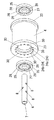
上記の接触ローラ4は軸部材6及び一対のベアリング25を介して基体21に取り付けられている。軸部材6は鋼材などの金属材料で管状に形成されており、その一端は閉塞されている。また、軸部材6の内側空間は軸方向に長い冷媒流通路7として形成されており、また、軸部材6の外周面には複数の吹き出し口8が開口されている。この吹き出し口8は上記冷媒流通路7と連通している。ベアリング25は外輪26と内輪27の間に複数の転動体(玉)28、28…を保持したボールベアリングなどを用いることができる。そして、二つのベアリング25、25を接触ローラ4の大径部24bに嵌め込んで装着し、このベアリング25、25の内輪27の内側に軸部材6を挿通することによって、図1に示すように、接触ローラ4と軸部材6とベアリング25とを一体的に組み立てることができる。また、接触ローラ4の両側に突出する軸部材6の両端部を基体21に設けた支持部21aに支持して取り付けることによって、エッジプレート3の上方において接触ローラ4を基体21に配設することができる。
The
図4に示すように、基体21に取り付けた軸部材6には冷媒供給管9が接続される。冷媒供給管9は耐熱性のあるホースなどを用いることができ、冷媒供給管9の一端は軸部材6の閉塞されていない方の側端部に接続されている。また、冷媒供給管9の他端は冷媒を圧送するためのポンプやボンベなどの冷媒供給装置(図示省略)に接続されている。冷媒としては常温の空気を用いることができるが、その他の公知の冷媒を用いることもできる。そして、本発明においては、上記の冷媒流通路7、吹き出し口8、冷媒供給管9、排気孔30、冷媒供給装置及び冷媒などにより冷却手段が形成されている。
As shown in FIG. 4, a
上記の余剰めっき液の除去装置Aを用いて溶融金属めっき板を製造するにあたっては、次のようにして行う。まず、鋼板などの長尺帯状の金属板1をその長尺方向に搬送しながらめっき浴20に上側から進入させた後、めっき浴20中のシンクロール31の下面に沿わせながら、その進行方向を上向きとなるように変更することによって、めっき浴20に進入させた金属板1をめっき浴20から引き上げる。この後、めっき浴20から引き上げられた金属板1は、めっき浴20の上方に設けた一対のワイピングノズル32、32の間を通過し、且つ上記一対の除去装置A、Aの間を通過するようにして進行する。そして、溶融金属めっきが施された上記金属板1がワイピングノズル32、32の間を通過する際に、金属板1の両面にワイピングノズル32、32からガスを吹き付けることによって、金属板1の表面に付着した溶融金属めっきの目付量(付着量)を調整する。また、溶融金属めっきが施された上記金属板1が一対の除去装置A、Aの間を通過する際に、金属板1の幅方向端部(金属板1の長尺方向と直交する方向の側端部)にエッジプレート3が近接することによって、金属板1の幅方向端部に付着した余剰のめっき液が除去される。この後、金属板1を冷却することによって、金属板1の表面に溶融金属めっき層が形成された溶融金属めっき板を形成することができる。
In manufacturing a molten metal plating plate using the above-described surplus plating solution removing apparatus A, the following steps are performed. First, after a long belt-like metal plate 1 such as a steel plate is conveyed from the upper side while being transported in the longitudinal direction, the traveling direction is moved along the lower surface of the
そして、溶融金属めっきが施された上記金属板1が一対の除去装置A、Aの間を通過する際に、除去装置Aの接触ローラ4は回転しながら金属板1の幅方向端面(側端面)2に常に接触しており、この接触により除去装置Aが金属板1の幅方向端面2に対して水平方向に近接離間移動することになって、エッジプレート3の帯材22を溶融金属めっきが施された金属板1の幅方向端面2に対向して所定の間隔で離間設置することができる。つまり、接触ローラ4は金属板1の幅方向端面2とエッジプレート3との間隔を常に3〜5mmに保持して規制するために設けられている。そして、接触ローラ4は常に金属板1の幅方向端面2と接触しているため、溶融金属めっきを施した直後の高温の金属板1で加熱されることになる。
And when the said metal plate 1 to which the molten metal plating was given passes between a pair of removal apparatuses A and A, the
そこで、本発明では冷却手段により接触ローラ4を内部から冷却しながら金属板1に接触させるものである。すなわち、冷媒供給装置から冷媒供給管9を通して空気等の冷媒を軸部材6の冷媒流通路7に供給し、冷媒供給路7に供給された冷媒を吹き出し口8から小径部24aに吹き出して接触ローラ4の内面に吹き付ける。これにより、接触ローラ4を内部から冷媒により冷却することができる。また、小径部24a内に供給された冷媒は排気孔30を通して接触ローラ4の外部に排気されるが、排気孔30を通過する冷媒によりベアリング25を冷却することもできる。ここで、接触ローラ4の内面には溝部33が形成されているので、溝部33を通じて排気孔30にまで冷媒を流れやすくすることができる。このようにして接触ローラ4及びベアリング25を約200℃程度にまで冷却することができる。尚、接触ローラ4及びベアリング25を冷却しない場合は約600℃程度にまで加熱される。
Therefore, in the present invention, the
このように本発明では、接触ローラ4を内部から冷却することができ、接触ローラ4に外部からエア等を吹き付けて冷却する場合に比べて、溶融金属めっきが施された金属板1に対するエア等の吹き付けが少なくなり、溶融金属めっき後の金属板1に表面欠陥等の不具合を発生させることなくなるものである。そして、冷却により接触ローラ4の熱による消耗が少なくなり、接触ローラ4の消耗による破損や回転不良などが無くなって金属板1の端部の損傷も無くすることができる。
As described above, in the present invention, the
1 金属板
2 幅方向端面
3 エッジプレート
4 接触ローラ
6 軸部材
7 冷媒流通路
8 吹き出し口
9 冷媒供給管
30 排気孔
33 溝部
DESCRIPTION OF SYMBOLS 1
30 Exhaust hole
33 Groove
Claims (2)
Priority Applications (1)
| Application Number | Priority Date | Filing Date | Title |
|---|---|---|---|
| JP2007286155A JP5113489B2 (en) | 2007-11-02 | 2007-11-02 | Apparatus for removing excess plating solution of molten metal plating and method for producing molten metal plated plate |
Applications Claiming Priority (1)
| Application Number | Priority Date | Filing Date | Title |
|---|---|---|---|
| JP2007286155A JP5113489B2 (en) | 2007-11-02 | 2007-11-02 | Apparatus for removing excess plating solution of molten metal plating and method for producing molten metal plated plate |
Publications (2)
| Publication Number | Publication Date |
|---|---|
| JP2009114479A JP2009114479A (en) | 2009-05-28 |
| JP5113489B2 true JP5113489B2 (en) | 2013-01-09 |
Family
ID=40781941
Family Applications (1)
| Application Number | Title | Priority Date | Filing Date |
|---|---|---|---|
| JP2007286155A Active JP5113489B2 (en) | 2007-11-02 | 2007-11-02 | Apparatus for removing excess plating solution of molten metal plating and method for producing molten metal plated plate |
Country Status (1)
| Country | Link |
|---|---|
| JP (1) | JP5113489B2 (en) |
Families Citing this family (2)
| Publication number | Priority date | Publication date | Assignee | Title |
|---|---|---|---|---|
| KR101847567B1 (en) | 2015-12-24 | 2018-04-10 | 주식회사 포스코 | Coated steel sheet |
| KR101778456B1 (en) * | 2016-07-28 | 2017-09-14 | 주식회사 포스코 | Apparatus for plating |
Family Cites Families (3)
| Publication number | Priority date | Publication date | Assignee | Title |
|---|---|---|---|---|
| JPS5693865A (en) * | 1979-12-27 | 1981-07-29 | Nisshin Steel Co Ltd | Strip support apparatus in molten metal plating |
| JP2692423B2 (en) * | 1991-05-31 | 1997-12-17 | 住友金属工業株式会社 | Deflector roll for cooling high temperature steel strip |
| JP3184790B2 (en) * | 1997-11-18 | 2001-07-09 | 大同鋼板株式会社 | Device for removing excess plating solution from hot-dip metal plating |
-
2007
- 2007-11-02 JP JP2007286155A patent/JP5113489B2/en active Active
Also Published As
| Publication number | Publication date |
|---|---|
| JP2009114479A (en) | 2009-05-28 |
Similar Documents
| Publication | Publication Date | Title |
|---|---|---|
| TWI480238B (en) | Production method and manufacturing apparatus of floating glass | |
| JP2007029789A (en) | Conveying apparatus for double-surface coated substrate | |
| JP5260370B2 (en) | Substrate processing equipment | |
| JP2013137139A (en) | Drying device and heat treatment system | |
| JP5113489B2 (en) | Apparatus for removing excess plating solution of molten metal plating and method for producing molten metal plated plate | |
| US9249489B2 (en) | Method and system for manufacturing metal-plated steel pipe | |
| JP2009094281A (en) | Substrate cooling device | |
| CN108431284A (en) | Plater and coating method | |
| JP4587834B2 (en) | Non-masking continuous partial plating equipment | |
| TWI270423B (en) | Method and apparatus for manufacturing metal material, metal material and metal workpiece | |
| KR101245696B1 (en) | Top roll of cooling tower | |
| JPWO2008072403A1 (en) | Non-contact liquid sealing apparatus and method | |
| JP3876749B2 (en) | Surface treatment method of plate material and heat radiating fin for heat exchanger | |
| JP2007138208A (en) | Liquid-wiping device | |
| JP2013123671A (en) | Film coating machine | |
| JP2012219356A (en) | Wiping device and hot dip plating apparatus using the same | |
| JP2005185997A (en) | Drying facility | |
| JP2007294598A (en) | Method for forming film of flexible printed board, and device therefor | |
| JP2009202041A (en) | Coating apparatus | |
| JP4804670B2 (en) | Equipment for cooling, heating or drying steel strip | |
| CN211662786U (en) | Multilayer composite film production equipment | |
| JPH04187750A (en) | Roll supporting device in hot dipping bath | |
| JP2019006614A (en) | Method and apparatus for manufacturing plate glass | |
| KR20090029915A (en) | Dry cleaner | |
| JP2009136780A (en) | Adhesive dip coating apparatus and adhesive dip coating method |
Legal Events
| Date | Code | Title | Description |
|---|---|---|---|
| A621 | Written request for application examination |
Free format text: JAPANESE INTERMEDIATE CODE: A621 Effective date: 20100830 |
|
| A977 | Report on retrieval |
Free format text: JAPANESE INTERMEDIATE CODE: A971007 Effective date: 20110202 |
|
| A131 | Notification of reasons for refusal |
Free format text: JAPANESE INTERMEDIATE CODE: A131 Effective date: 20120626 |
|
| A521 | Written amendment |
Free format text: JAPANESE INTERMEDIATE CODE: A523 Effective date: 20120827 |
|
| TRDD | Decision of grant or rejection written | ||
| A01 | Written decision to grant a patent or to grant a registration (utility model) |
Free format text: JAPANESE INTERMEDIATE CODE: A01 Effective date: 20120925 |
|
| A01 | Written decision to grant a patent or to grant a registration (utility model) |
Free format text: JAPANESE INTERMEDIATE CODE: A01 |
|
| A61 | First payment of annual fees (during grant procedure) |
Free format text: JAPANESE INTERMEDIATE CODE: A61 Effective date: 20121012 |
|
| FPAY | Renewal fee payment (event date is renewal date of database) |
Free format text: PAYMENT UNTIL: 20151019 Year of fee payment: 3 |
|
| R150 | Certificate of patent or registration of utility model |
Ref document number: 5113489 Country of ref document: JP Free format text: JAPANESE INTERMEDIATE CODE: R150 Free format text: JAPANESE INTERMEDIATE CODE: R150 |
|
| R250 | Receipt of annual fees |
Free format text: JAPANESE INTERMEDIATE CODE: R250 |
|
| R250 | Receipt of annual fees |
Free format text: JAPANESE INTERMEDIATE CODE: R250 |
|
| R250 | Receipt of annual fees |
Free format text: JAPANESE INTERMEDIATE CODE: R250 |