KR20170018995A - Heat pump system for vehicle - Google Patents
Heat pump system for vehicle Download PDFInfo
- Publication number
- KR20170018995A KR20170018995A KR1020150112374A KR20150112374A KR20170018995A KR 20170018995 A KR20170018995 A KR 20170018995A KR 1020150112374 A KR1020150112374 A KR 1020150112374A KR 20150112374 A KR20150112374 A KR 20150112374A KR 20170018995 A KR20170018995 A KR 20170018995A
- Authority
- KR
- South Korea
- Prior art keywords
- air
- outside
- evaporator
- condenser
- car
- Prior art date
Links
Images


Classifications
-
- B—PERFORMING OPERATIONS; TRANSPORTING
- B60—VEHICLES IN GENERAL
- B60H—ARRANGEMENTS OF HEATING, COOLING, VENTILATING OR OTHER AIR-TREATING DEVICES SPECIALLY ADAPTED FOR PASSENGER OR GOODS SPACES OF VEHICLES
- B60H1/00—Heating, cooling or ventilating [HVAC] devices
- B60H1/00642—Control systems or circuits; Control members or indication devices for heating, cooling or ventilating devices
- B60H1/00814—Control systems or circuits characterised by their output, for controlling particular components of the heating, cooling or ventilating installation
- B60H1/00878—Control systems or circuits characterised by their output, for controlling particular components of the heating, cooling or ventilating installation the components being temperature regulating devices
- B60H1/00899—Controlling the flow of liquid in a heat pump system
-
- B—PERFORMING OPERATIONS; TRANSPORTING
- B60—VEHICLES IN GENERAL
- B60H—ARRANGEMENTS OF HEATING, COOLING, VENTILATING OR OTHER AIR-TREATING DEVICES SPECIALLY ADAPTED FOR PASSENGER OR GOODS SPACES OF VEHICLES
- B60H1/00—Heating, cooling or ventilating [HVAC] devices
- B60H1/00507—Details, e.g. mounting arrangements, desaeration devices
- B60H1/00514—Details of air conditioning housings
-
- B—PERFORMING OPERATIONS; TRANSPORTING
- B60—VEHICLES IN GENERAL
- B60H—ARRANGEMENTS OF HEATING, COOLING, VENTILATING OR OTHER AIR-TREATING DEVICES SPECIALLY ADAPTED FOR PASSENGER OR GOODS SPACES OF VEHICLES
- B60H1/00—Heating, cooling or ventilating [HVAC] devices
- B60H1/00507—Details, e.g. mounting arrangements, desaeration devices
- B60H1/00557—Details of ducts or cables
- B60H1/00564—Details of ducts or cables of air ducts
-
- B—PERFORMING OPERATIONS; TRANSPORTING
- B60—VEHICLES IN GENERAL
- B60H—ARRANGEMENTS OF HEATING, COOLING, VENTILATING OR OTHER AIR-TREATING DEVICES SPECIALLY ADAPTED FOR PASSENGER OR GOODS SPACES OF VEHICLES
- B60H1/00—Heating, cooling or ventilating [HVAC] devices
- B60H1/02—Heating, cooling or ventilating [HVAC] devices the heat being derived from the propulsion plant
- B60H1/04—Heating, cooling or ventilating [HVAC] devices the heat being derived from the propulsion plant from cooling liquid of the plant
- B60H1/08—Heating, cooling or ventilating [HVAC] devices the heat being derived from the propulsion plant from cooling liquid of the plant from other radiator than main radiator
- B60H1/10—Heating, cooling or ventilating [HVAC] devices the heat being derived from the propulsion plant from cooling liquid of the plant from other radiator than main radiator the other radiator being situated in a duct capable of being connected to atmosphere outside vehicle
- B60H1/12—Heating, cooling or ventilating [HVAC] devices the heat being derived from the propulsion plant from cooling liquid of the plant from other radiator than main radiator the other radiator being situated in a duct capable of being connected to atmosphere outside vehicle using an air blower
-
- B—PERFORMING OPERATIONS; TRANSPORTING
- B60—VEHICLES IN GENERAL
- B60H—ARRANGEMENTS OF HEATING, COOLING, VENTILATING OR OTHER AIR-TREATING DEVICES SPECIALLY ADAPTED FOR PASSENGER OR GOODS SPACES OF VEHICLES
- B60H1/00—Heating, cooling or ventilating [HVAC] devices
- B60H1/24—Devices purely for ventilating or where the heating or cooling is irrelevant
- B60H1/248—Air-extractors, air-evacuation from the vehicle interior
-
- B—PERFORMING OPERATIONS; TRANSPORTING
- B60—VEHICLES IN GENERAL
- B60H—ARRANGEMENTS OF HEATING, COOLING, VENTILATING OR OTHER AIR-TREATING DEVICES SPECIALLY ADAPTED FOR PASSENGER OR GOODS SPACES OF VEHICLES
- B60H1/00—Heating, cooling or ventilating [HVAC] devices
- B60H1/32—Cooling devices
- B60H1/3204—Cooling devices using compression
- B60H1/3205—Control means therefor
- B60H1/3213—Control means therefor for increasing the efficiency in a vehicle heat pump
-
- B—PERFORMING OPERATIONS; TRANSPORTING
- B60—VEHICLES IN GENERAL
- B60H—ARRANGEMENTS OF HEATING, COOLING, VENTILATING OR OTHER AIR-TREATING DEVICES SPECIALLY ADAPTED FOR PASSENGER OR GOODS SPACES OF VEHICLES
- B60H1/00—Heating, cooling or ventilating [HVAC] devices
- B60H1/32—Cooling devices
- B60H1/3204—Cooling devices using compression
- B60H1/3229—Cooling devices using compression characterised by constructional features, e.g. housings, mountings, conversion systems
-
- F—MECHANICAL ENGINEERING; LIGHTING; HEATING; WEAPONS; BLASTING
- F25—REFRIGERATION OR COOLING; COMBINED HEATING AND REFRIGERATION SYSTEMS; HEAT PUMP SYSTEMS; MANUFACTURE OR STORAGE OF ICE; LIQUEFACTION SOLIDIFICATION OF GASES
- F25B—REFRIGERATION MACHINES, PLANTS OR SYSTEMS; COMBINED HEATING AND REFRIGERATION SYSTEMS; HEAT PUMP SYSTEMS
- F25B30/00—Heat pumps
- F25B30/02—Heat pumps of the compression type
Abstract
Description
본 발명은 차량용 히트 펌프 시스템에 관한 것으로써, 더욱 상세하게는 공조케이스 내부에 증발기가 설치되는 냉풍통로와 응축기가 설치되는 온풍통로를 구비하여 냉,난방을 수행하는 히트 펌프 시스템에서, 난방모드시 내기와 외기의 혼합 공기를 상기 증발기와 응축기측으로 각각 공급하여 익스트랙터를 통해 차실외로 배출될 내기의 일정량을 재순환시켜 증발기를 통과시킨 후 배출시키도록 한 차량용 히트 펌프 시스템에 관한 것이다.The present invention relates to a heat pump system for a vehicle. More particularly, the present invention relates to a heat pump system for performing cooling and heating by providing a cold air passage in which an evaporator is installed in an air conditioning case and a hot air passage in which a condenser is installed, The present invention relates to a heat pump system for a vehicle, in which a mixed air of an indoor air and an outdoor air is supplied to the evaporator and a condenser, respectively, and a certain amount of indoor air to be discharged to the outside of the car through an extractor is recirculated and passed through an evaporator.
일반적인 차량용 에어컨시스템은 통상, 도 1에 도시된 바와 같이, 냉매를 압축하여 송출하는 압축기(Compressor)(1), 압축기(1)에서 송출되는 고압의 냉매를 응축하는 응축기(Condenser)(2), 응축기(2)에서 응축되어 액화된 냉매를 교축하는 예컨대 팽창밸브(Expansion Valve)(3), 그리고, 상기 팽창밸브(3)에 의해 교축된 저압의 액상 냉매를 차실내측으로 송풍되는 공기와 열교환하여 증발시킴으로써 냉매의 증발잠열에 의한 흡열작용으로 실내에 토출되는 공기를 냉각하는 증발기(Evaporator)(4) 등이 냉매 파이프로 연결되어 이루어진 냉동사이클로 구성되며, 다음과 같은 냉매 순환과정을 통하여 자동차 실내를 냉방한다.1, a general automotive air conditioning system generally includes a
상기 에어컨시스템의 냉방스위치(미도시)가 온(On) 되면, 먼저 압축기(1)가 엔진 또는 모터의 동력으로 구동하면서 저온 저압의 기상 냉매를 흡입,압축하여 고온 고압의 기체 상태로 응축기(2)로 송출하고, 응축기(2)는 그 기상 냉매를 외기와 열교환하여 고온 고압의 액체로 응축한다. 이어, 응축기(2)에서 고온 고압의 상태로 송출되는 액상 냉매는 팽창밸브(3)의 교축작용으로 급속히 팽창되어 저온 저압의 습포화 상태로 증발기(4)로 보내어지고, 증발기(4)는 그 냉매를 블로어(미도시)가 차실내로 송풍하는 공기와 열교환시킨다. 이에 냉매는 증발기(4)에서 증발하여 저온 저압의 기체 상태로 배출되고 다시 압축기(1)에 흡입되어 상술한 바와 같은 냉동사이클을 재순환하게 된다.When the cooling switch (not shown) of the air conditioning system is turned on, the
상기 증발기는 차실내측에 설치된 공조케이스의 내부에 설치되어 냉방 역할을 하게 되는데, 즉, 블로어(미도시)가 송풍하는 공기가 상기 증발기(4)를 거치면서 증발기(4)내를 순환하는 액상 냉매의 증발 잠열로 냉각되어 차가워진 상태로 차실내에 토출됨으로써 이루어진다.The evaporator is installed inside the air conditioner case installed inside the vehicle compartment to function as a cooling device. That is, the air blown by the blower (not shown) flows through the
또한, 차실내의 난방은, 상기 공조케이스의 내부에 설치되어 엔진 냉각수가 순환하는 히터코어(미도시)를 이용하거나 또는 상기 공조케이스의 내부에 설치되는 전기가열식히터(미도시)를 이용하게 된다.The heating of the interior of the vehicle is performed by using a heater core (not shown) provided inside the air conditioning case and circulating engine cooling water, or an electric heater (not shown) installed inside the air conditioning case .
한편, 상기 응축기(2)는 차량의 전방측에 설치되어 공기와 열교환하면서 방열을 하게 된다.On the other hand, the
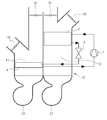
최근에는, 냉동사이클만을 이용하여 냉,난방을 수행하는 히트 펌프 시스템이 개발되고 있는바, 도 2에 도시된 바와 같이, 하나의 공조케이스(10) 내부에 냉풍통로(11)와 온풍통로(12)를 좌,우 구획되게 형성하고, 상기 냉풍통로(11)에는 냉방을 위한 증발기(4)를 설치하며, 상기 온풍통로(12)에는 난방을 위한 응축기(2)를 설치한 구조이다.2. Description of the Related Art In recent years, a heat pump system has been developed that performs cooling and heating using only a refrigeration cycle. As shown in Fig. 2, a
이때, 상기 공조케이스(10)의 출구측에는 차실내로 공기를 공급하는 공기토출구(15)와, 차실외로 공기를 방출하는 공기방출구(16)가 형성된다.At this time, an
또한, 상기 냉풍통로(11)와 온풍통로(12)의 각 입구측에는 개별작동하는 블로어(20)가 각각 설치된다.The
상기 냉풍통로(11)와 온풍통로(12)가 좌,우(차량 폭방향)로 배치되므로, 상기 두 개의 블로어(20)도 좌,우로 배치된다.Since the
따라서, 냉방모드시에는 상기 냉풍통로(11)의 증발기(4)를 통과하면서 냉각된 냉풍이 공기토출구(15)를 통해 차실내로 토출되어 냉방하게 되고, 이때 상기 온풍통로(12)의 응축기(2)를 통과하면서 가열된 온풍은 공기방출구(16)를 통해 차실외로 배출되게 된다.Therefore, in the cooling mode, the cold air cooled while passing through the
난방모드시에는 상기 온풍통로(12)의 응축기(2)를 통과하면서 가열된 온풍이 상기 공기토출구(15)를 통해 차실내로 토출되어 난방하게 되고, 이때 상기 냉풍통로(11)의 증발기(4)를 통과하면서 냉각된 냉풍은 공기방출구(16)를 통해 차실외로 배출되게 된다.In the heating mode, hot air heated while passing through the
그리고, 도 3과 같이 통상적으로 차량의 트렁크측에는 차실내의 공기(내기)를 차실외로 배출시키는 익스트랙터(Extractor)(50)가 설치되는데, 상기 익스트랙터(50)는 차실내와 차실외의 차압에 의해 열리게 된다.3, an
따라서, 상기 공조케이스(10)를 통해 냉풍 또는 온풍이 차실내로 공급되면, 차실내를 순환하는 공기(내기)의 일정량이 상기 익스트랙터(50)를 통해 차실외로 배출되게 된다.Accordingly, when cold air or warm air is supplied through the
일예로, 난방모드시 차실내로 온풍이 유입되는데, 이때 VOC와 유리창 습기 문제로 인해 차실내 공기(내기)의 일정량이 상기 익스트랙터(50)를 통해 차실외로 배출되는 것이다.For example, in the heating mode, hot air flows into the car interior. At this time, a certain amount of the car interior air (inside air) is discharged to the outside of the car through the
그러나, 종래에는 난방모드시 상기 익스트랙터(50)를 통해 차실외로 배출되는 내기(난방 공기)를 활용하지 못함은 물론 특히 난방 성능을 향상하기 위해 히트 펌프 시스템의 냉동사이클에 칠러(미도시)를 추가 설치하여 차량 전장품의 폐열로 데워진 냉각수와 냉매를 열교환시킴으로써, 냉매 압력과 온도를 높여주어 난방 성능을 향상하였는데, 이 경우 난방 성능 향상을 위해 상기 칠러와 같은 추가 부품이 구성되어야 하는 문제가 있었다.However, conventionally, in the heating mode, it is not possible to utilize the inside air (heating air) discharged to the outside of the car through the
상기한 문제점을 해결하기 위한 본 발명의 목적은 공조케이스 내부에 증발기가 설치되는 냉풍통로와 응축기가 설치되는 온풍통로를 구비하여 냉,난방을 수행하는 히트 펌프 시스템에서, 난방모드시 내기와 외기의 혼합 공기를 상기 증발기와 응축기측으로 각각 공급하여 익스트랙터를 통해 차실외로 배출될 내기의 일정량을 재순환시켜 증발기를 통과시킨 후 배출시킴으로써, 추가 부품 구성 없이 냉매사이클에서 냉매 압력과 온도를 상승시켜 난방 성능을 향상할 수 있는 차량용 히트 펌프 시스템을 제공하는데 있다.In order to solve the above problems, an object of the present invention is to provide a heat pump system that includes a cold air passage in which an evaporator is installed and a hot air passage in which a condenser is installed, The mixed air is supplied to the evaporator and the condenser, and a certain amount of the air to be discharged to the outside of the car is supplied through the evaporator and the condenser, and then the refrigerant is passed through the evaporator and discharged. Thus, the refrigerant pressure and temperature are increased in the refrigerant cycle The present invention provides a heat pump system for a vehicle that can improve the performance of a vehicle.
상기한 목적을 달성하기 위한 본 발명은, 압축기, 응축기, 팽창수단, 증발기(104)가 냉매순환라인으로 연결되어 이루어진 차량용 히트 펌프 시스템에 있어서, 상기 증발기가 설치되는 냉풍통로 및 상기 응축기가 설치되는 온풍통로를 구비하고, 상기 증발기를 통과한 냉풍과 응축기를 통과한 온풍을 차실내로 공급하거나 차실외로 방출하는 공조케이스와, 상기 공조케이스의 입구측에 설치되어 상기 냉풍통로로 공기를 송풍하는 제1블로어 및 상기 온풍통로로 공기를 송풍하는 제2블로어와, 상기 제1,2블로어측에 연결 설치되어 내기와 외기를 공급하는 내,외기 공급수단과, 내기와 외기의 혼합 공기를 상기 증발기와 응축기측으로 각각 공급하도록 상기 내,외기 공급수단을 제어하는 제어부를 포함하여 이루어진 것을 특징으로 한다.According to an aspect of the present invention, there is provided a heat pump system for a vehicle including a compressor, a condenser, an expansion means, and an evaporator connected to a refrigerant circulation line, wherein the cold air passage, An air conditioning case provided with a hot air passage for supplying cold air having passed through the evaporator and hot air passing through the condenser to the inside or outside of the car interior of the vehicle, A second blower for blowing air to the first blower and the hot air passage; inner and outer air supply means connected to the first and second blower sides for supplying indoor and outdoor air; And a control unit for controlling the inside / outside air supply unit to supply the outside air and the outside air to the condenser, respectively.
본 발명은, 공조케이스 내부에 증발기가 설치되는 냉풍통로와 응축기가 설치되는 온풍통로를 구비하여 냉,난방을 수행하는 히트 펌프 시스템에서, 난방모드시 내기와 외기의 혼합 공기를 상기 증발기와 응축기측으로 각각 공급하여 익스트랙터를 통해 차실외로 배출될 내기의 일정량을 재순환시켜 증발기를 통과시킨 후 배출시킴으로써, 추가 부품 구성 없이 냉매사이클에서 냉매 압력과 온도를 상승시켜 난방 성능을 향상할 수 있다.The present invention relates to a heat pump system for performing cooling and heating by providing a cold air passage in which an evaporator is installed and a warm air passage in which a condenser is installed in an air conditioning case and a mixed air of air and outdoor air in a heating mode is supplied to the evaporator and a condenser And a predetermined amount of the air to be discharged to the outside of the vehicle through the extractor is recirculated and passed through the evaporator and then discharged. Thus, the refrigerant pressure and the temperature can be increased in the refrigerant cycle without additional components, thereby improving the heating performance.
도 1은 일반적인 차량용 에어컨시스템의 냉동사이클을 나타내는 구성도,
도 2는 종래의 차량용 히트 펌프 시스템을 나타내는 도면,
도 3은 종래의 차량용 히트 펌프 시스템의 난방모드시 공기유동을 나타내는 도면,
도 4는 본 발명에 따른 차량용 히트 펌프 시스템을 나타내는 사시도,
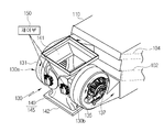
도 5는 본 발명에 따른 차량용 히트 펌프 시스템에서 송풍장치를 나타내는 부분 사시도,
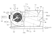
도 6은 도 4의 A측에서 바라본 측면도,
도 7은 본 발명에 따른 차량용 히트 펌프 시스템의 난방모드시 공기유동을 나타내는 도면,
도 8은 본 발명에 따른 차량용 히트 펌프 시스템의 난방모드시 송풍장치를 나타내는 단면도,
도 9는 본 발명에 따른 차량용 히트 펌프 시스템의 냉방모드를 나타내는 도면,
도 10은 본 발명에 따른 차량용 히트 펌프 시스템의 난방모드를 나타내는 도면이다.BRIEF DESCRIPTION OF THE DRAWINGS FIG. 1 is a view showing a refrigeration cycle of a general automotive air conditioning system;
2 is a view showing a conventional vehicle heat pump system,
3 is a view showing air flow in a heating mode of a conventional vehicle heat pump system,
4 is a perspective view showing a heat pump system for a vehicle according to the present invention,
5 is a partial perspective view showing a blower in the heat pump system for a vehicle according to the present invention,
Fig. 6 is a side view seen from the side A in Fig. 4,
7 is a view showing an air flow in a heating mode of a vehicle heat pump system according to the present invention,
FIG. 8 is a cross-sectional view showing a blower in a heating mode of a heat pump system for a vehicle according to the present invention,
9 is a view showing a cooling mode of a heat pump system for a vehicle according to the present invention,
10 is a view showing a heating mode of a vehicle heat pump system according to the present invention.
이하, 본 발명을 첨부된 도면을 참조하여 상세히 설명하면 다음과 같다.Hereinafter, the present invention will be described in detail with reference to the accompanying drawings.
도시된 바와 같이, 본 발명에 따른 차량용 히트 펌프 시스템은, 압축기(미도시) -> 응축기(102) -> 팽창수단(미도시) -> 증발기(104)를 냉매순환라인(미도시)으로 연결하여, 상기 증발기(104)를 통해 냉방을 수행하고 상기 응축기(102)를 통해 난방을 수행하는 것이다.The heat pump system for a vehicle according to the present invention includes a compressor (not shown) -> a condenser 102 -> an expansion means (not shown) -> an
먼저, 상기 압축기는 동력공급원(엔진 또는 모터 등)으로부터 동력을 전달받아 구동하면서 증발기(104)로부터 토출된 저온 저압의 기상 냉매를 흡입 압축하여 고온 고압의 기체 상태로 토출하게 된다.First, the compressor receives the power from a power source (such as an engine or a motor), sucks and compresses the low-temperature low-pressure gaseous refrigerant discharged from the
상기 응축기(102)는, 상기 압축기에서 배출되어 응축기(102)의 내부를 유동하는 고온 고압의 기상 냉매와 상기 응축기(102)를 통과하는 공기를 상호 열교환시키게 되며, 이 과정에서 냉매는 응축되고, 공기는 가열되어 온풍으로 바뀌게 된다.The
이러한 상기 응축기(102)는, 냉매순화라인(냉매파이프)을 지그재그 형태로 구성한 후 방열핀(미도시)을 설치한 구조, 또는 복수개의 튜브(미도시)를 적층하고 각 튜브의 사이에 방열핀을 설치한 구조로 구성할 수 있다.The
따라서, 상기 압축기에서 배출된 고온 고압의 기상 냉매가 상기 지그재그 형태의 냉매순환라인 또는 복수개 튜브를 따라 유동하면서 공기와 열교환하여 응축되고, 이때 상기 응축기(102)를 통과하는 공기는 가열되어 온풍으로 바뀌게 되는 것이다.Accordingly, the gaseous refrigerant of high temperature and pressure discharged from the compressor flows through the zigzag refrigerant circulation line or a plurality of tubes and is heat-exchanged with the air to be condensed. At this time, the air passing through the
그리고, 상기 팽창수단(미도시)은 상기 응축기(102)에서 배출되어 유동하는 액상 냉매를 교축작용으로 급속히 팽창시켜 저온 저압의 습포화 상태로 증발기(104)로 보내게 된다.The expansion means (not shown) rapidly expands the liquid-phase refrigerant discharged from the
상기 팽창수단으로는 팽창밸브 또는 오리피스 구조를 사용할 수 있다.As the expansion means, an expansion valve or an orifice structure can be used.
상기 증발기(104)는 상기 팽창수단에서 배출되어 유동하는 저압의 액상 냉매를 공조케이스(110)내의 공기와 열교환시켜 증발시킴으로써 냉매의 증발잠열에 의한 흡열작용으로 공기를 냉각하게 된다.The
계속해서, 상기 증발기(104)에서 증발하여 배출된 저온 저압의 기상 냉매는 다시 압축기에 흡입되어 상술한 바와 같은 사이클을 재순환하게 된다.Subsequently, the gaseous low-temperature and low-pressure gaseous refrigerant evaporated in the
아울러, 상기와 같은 냉매순환과정에서, 차실내의 냉방은, 송풍장치(130)에서 송풍되는 공기가 공조케이스(110)내로 유입되어 증발기(104)를 통과하면서 증발기(104)의 내부를 순환하는 액상 냉매의 증발 잠열로 냉각되어 차가워진 상태로 차실내에 토출됨으로써 이루어지고,In the refrigerant circulation process as described above, air in the interior of the vehicle is circulated through the
차실내의 난방은, 송풍장치(130)에서 송풍되는 공기가 공조케이스(110)내로 유입되어 응축기(102)를 통과하면서 응축기(102)의 내부를 순환하는 고온 고압의 기상 냉매의 방열로 가열되어 뜨거워진 상태로 차실내에 토출됨으로써 이루어진다.In the heating of the interior of the vehicle, the air blown from the
그리고, 상기 공조케이스(110)의 내부에는, 그 내부를 상,하로 구획하는 구획벽(113)에 의해 냉풍통로(111) 및 온풍통로(112)가 상,하방향으로 서로 구획 형성된다.In the interior of the
즉, 상기 냉풍통로(111)는 상기 구획벽(113)을 기준으로 상부에 형성되고, 상기 온풍통로(112)는 상기 구획벽(113)을 기준으로 하부에 형성된다.That is, the
또한, 상기 냉풍통로(111)에는 상기 증발기(104)를 설치하고, 상기 온풍통로(112)에는 상기 응축기(102)를 설치된다. 아울러 상기 냉풍통로(111)와 온풍통로(112)의 상,하 배치 구조로 인해 상기 증발기(104)와 상기 응축기(102)도 상,하로 배치되게 된다.The
상기 공조케이스(110)는, 상기 증발기(104)가 설치된 냉풍통로(111)에는 냉풍이 유동하고, 상기 응축기(102)가 설치된 온풍통로(112)에는 온풍이 유동하게 되며, 상기 증발기(104)를 통과한 냉풍과 응축기(102)를 통과한 온풍을 차실내로 공급하거나 차실외로 방출하게 된다.In the
상기에서는 증발기(104)가 구획벽(113)의 상부에 설치되고, 상기 응축기(102)가 구획벽(113)의 하부에 설치된 경우에 대해서만 설명하였지만, 이와는 반대로 상기 증발기(104)를 구획벽(113)의 하부에 설치하고, 상기 응축기(102)를 구획벽(113)의 상부에 설치하는 것도 가능하다.The case where the
한편, 상기 공조케이스(110) 및 송풍장치(130)는, 도 7과 같이 차실내 승객룸을 형성하는 격벽의 외측에 설치되는데, 일예로 차량의 엔진룸내에 설치될 수 있다.Meanwhile, the
그리고, 상기 공조케이스(110)의 입구측에 설치되는 송풍장치(130)는, 상기 공조케이스(110)의 냉풍통로(111) 입구(111a)측에 연결 설치되어 냉풍통로(111)로 공기를 송풍하는 제1블로어(130a)와, 상기 공조케이스(110)의 온풍통로(112) 입구(112a)측에 연결 설치되어 온풍통로(112)로 공기를 송풍하는 제2블로어(130b)로 이루어진다.The
상기 제1블로어(130a)와 제2블로어(130b)는, 차량의 폭방향으로 서로 이격되어 설치된다.The
상기 제1블로어(130a)는, 상기 공조케이스(110)의 냉풍통로(111) 입구(111a)측에 연결되는 스크롤케이스(131)와, 상기 스크롤케이스(131)의 내부에 회전가능하게 설치되는 송풍팬(132)과, 상기 스크롤케이스(131)의 일측면에 형성되어 내,외기가 유입되는 인렛링(131a)과, 상기 스크롤케이스(131)의 타측면에 설치되어 상기 송풍팬(132)을 회전시키는 모터(133)로 이루어진다.The
상기 인렛링(131a)은, 상기 스크롤케이스(131)에서 내,외기공급수단(145)의 인테이크덕트(140)가 결합되는 일측면에 형성된다.The
상기 제2블로어(130b)는, 상기 공조케이스(110)의 온풍통로(112) 입구(112a)측에 연결되는 스크롤케이스(135)와, 상기 스크롤케이스(135)의 내부에 회전가능하게 설치되는 송풍팬(136)과, 상기 스크롤케이스(135)의 일측면에 형성되어 내,외기가 유입되는 인렛링(135a)과, 상기 스크롤케이스(135)의 타측면에 설치되어 상기 송풍팬(136)을 회전시키는 모터(137)로 이루어진다.The
상기 인렛링(135a)은, 상기 스크롤케이스(135)에서 내,외기공급수단(145)의 인테이크덕트(140)가 결합되는 일측면에 형성된다.The
또한, 상기 제1블로어(130a)의 인렛링(131a)과 상기 제2블로어(130b)의 인렛링(135a)은 서로 마주하도록 형성된다.The
한편, 상기 제1,2블로어(130a,130b)의 스크롤케이스(131,135)는, 각각 내부에 설치된 송풍팬(132,136)을 중심으로 스크롤 형태로 형성된다.The
그리고, 상기 제1,2블로어(130a,130b)측에 연결 설치되어 내기와 외기를 공급하는 내,외기 공급수단(145)이 설치된다.The first and
상기 내,외기 공급수단(145)은, 상기 제1,2블로어(130a,130b)와 연통되게 연결되며 내기유입구(142) 및 외기유입구(141)를 구비한 인테이크 덕트(140)와, 상기 제1블로어(130a)에 대해 상기 내,외기유입구(141,142)를 선택적으로 개방하는 제1내외기전환도어(147)와, 상기 제2블로어(130b)에 대해 상기 내,외기유입구(141,142)를 선택적으로 개방하는 제2내외기전환도어(148)로 이루어진다.The internal and external air supply means 145 includes an
상기 인테이크덕트(140)는, 상기 제1블로어(130a)와 제2블로어(130b)의 사이에 하나가 설치되어, 상기 제1,2블로어(130a,130b)가 상기 하나의 인테이크덕트(140)를 공용으로 사용하게 되는 것이다.The
이처럼, 상기 인테이크덕트(140)를 상기 제1블로어(130a)와 제2블로어(130b)의 사이에 설치함으로써, 각각 개별 작동하는 두 개의 블로어(130a,130b)를 사용하는 시스템에서 하나의 인테이크덕트(140)를 사용하므로 공간 효율을 극대화 할 수 있고, 이로인해 시스템의 크기 및 비용을 줄일 수 있다.By providing the
상기 인테이크덕트(140)에는, 외기를 유입하는 외기유입구(141)와, 내기를 유입하는 내기유입구(142)가 구비되며, 이때 상기 외기유입구(141)는 인테이크덕트(140)의 상부에 형성되고, 내기유입구(142)는 인테이크덕트(140)의 하부에 형성되는 것이 바람직하다.The
상기 제1내외기전환도어(147)와 상기 제2내외기전환도어(148)는 상기 인테이크덕트(140)의 내기유입구(142)와 외기유입구(141)의 사이에 각각 설치되며, 이때 상기 제1내외기전환도어(147)는 돔형 도어로 이루어져 상기 제1블로어(130a)의 일측에 배치되고, 상기 제2내외기전환도어(148)도 돔형 도어로 이루어져 상기 제2블로어(130b)의 일측에 배치된다.The first indoor /
이처럼, 하나의 인테이크덕트(140)를 상기 제1,2블로어(130a,130b)의 사이에 설치하고, 상기 인테이크덕트(140)의 내부에는 제1,2내외기전환도어(147,148)를 설치하여, 상기 인테이크덕트(140)의 내,외기유입구(141,142)로 유입되는 내,외기를 상기 제1,2블로어(130a,130b)를 통해 상기 증발기와 응축기측으로 선택적으로 공급할 수 있다.As described above, one
한편, 상기 인테이크덕트(140)의 외기유입구(141)는 차량의 외부와 연통되고, 상기 인테이크덕트(140)의 내기유입구(142)는 차실내와 연통된다.Meanwhile, the
이때, 상기 공조케이스(110)에는, 상기 인테이크덕트(140)의 내기유입구(142)와 차실내를 연결하는 내기유입덕트(142a)가 설치된다.At this time, the
또한, 상기 외기유입구(141)와 내기유입구(142)에는, 각각 에어필터(141a,142a)가 설치되어, 외기유입구(141)와 내기유입구(142)로 유입되는 공기 중에 포함된 불순물을 제거하게 된다.
그리고, 상기 공조케이스(110)의 냉풍통로(111) 출구측에는, 상기 증발기(104)를 통과한 냉풍을 차실내로 토출하는 냉풍토출구(111b) 및 차실외로 방출하는 냉풍방출구(119a)와, 상기 냉풍토출구(111b)와 냉풍방출구(119a)를 개폐하는 냉풍 모드도어(120)가 구비되고,A cool
상기 공조케이스(110)의 온풍통로(112) 출구측에는, 상기 응축기(102)를 통과한 온풍을 차실내로 토출하는 온풍토출구(112b) 및 차실외로 방출하는 온풍방출구(119b)와, 상기 온풍토출구(112b)와 온풍방출구(119b)를 개폐하는 온풍 모드도어(121)가 구비된다.A warm
상기 냉풍 모드도어(120)와 온풍 모드도어(121)는 돔형 도어로 구성된다.The cold-
따라서, 냉방모드시에는 상기 냉풍토출구(111b)와 온풍방출구(119b)가 개방되어, 상기 냉풍통로(111)를 유동하는 공기는 증발기(104)를 통과하면서 냉풍으로 바뀐 후 냉풍토출구(111b)를 통해 차실내로 공급되어 냉방하게 되고, 이때 상기 온풍통로(112)를 유동하는 공기는 응축기(102)를 통과하면서 온풍으로 바뀐 후 온풍방출구(119b)를 통해 차실외로 배출되게 된다.Accordingly, in the cooling mode, the cold
난방모드시에는 온풍토출구(112b)와 냉풍방출구(119a)가 개방되어, 상기 온풍통로(112)를 유동하는 공기는 응축기(102)를 통과하면서 온풍으로 바뀐 후 온풍토출구(112b)를 통해 차실내로 공급되어 난방하게 되고, 이때 상기 냉풍통로(111)를 유동하는 공기는 증발기(104)를 통과하면서 냉풍으로 바뀐 후 냉풍방출구(119a)를 통해 차실외로 배출되게 된다.In the heating mode, the hot
그리고, 상기 차량에는 차실내의 공기를 차실외로 배출시킬 수 있도록 익스트랙터(Extractor)(50)가 설치된다.The vehicle is provided with an
상기 익스트랙터(50)는 차실내와 차실외의 차압에 의해 열리게 되며 차량의 트렁크측에 설치된다. 한편, 상기 익스트랙터(50)는 공지된 것이므로 구조에 대한 상세 설명은 생략한다.The extractor (50) is opened by a differential pressure between the vehicle interior and the vehicle exterior, and is installed on the trunk side of the vehicle. Meanwhile, since the
따라서, 상기 공조케이스(110)를 통해 냉풍 또는 온풍이 차실내로 공급되면, 차실내,외의 차압에 의해 상기 익스트랙터(50)가 열리게 되고, 이때 차실내 내기의 일정량이 상기 익스트랙터(50)를 통해 차실외로 배출되게 된다.Accordingly, when cold air or warm air is supplied to the room through the
그리고, 본 발명에서는, 상기 익스트랙터(50)를 통해 차실외로 배출되던 차실내 내기(난방 공기)를 재순환시켜 증발기(104)를 통과시킨 후 배출시키게 되는데, 다시말해 차실외로 버려지던 폐 열원을 재활용하여 증발기(104)와 열교환시킨후 배출시킴으로써 추가 부품 구성 없이 냉매사이클에서 냉매 압력과 온도를 상승시켜 난방 성능을 향상할 수 있도록 한 것이다.In the present invention, the interior of the car (heating air), which has been discharged to the outside of the car through the
이를 위해, 본 발명은, 난방모드시, 도 8과 같이, 내기와 외기의 혼합 공기를 상기 증발기(104)와 응축기(102)측으로 각각 공급하도록 상기 내,외기 공급수단(145)을 제어하는 제어부(150)가 구비된다.To this end, according to the present invention, in the heating mode, as shown in Fig. 8, a control unit for controlling the inside / outside air supply means 145 to supply mixed air of the inside air and the outside air to the
즉, 상기 제어부(150)는, 난방모드시 상기 익스트랙터(50)로 배출될 내기의 일정량을 상기 증발기(104)와 응축기(102)측으로 재순환시키도록 상기 내,외기 공급수단(145)의 제1,2내외기전환도어(147,148)를 제어하게 된다.That is, the
다시말해, 상기 익스트랙터(50)로 배출될 내기를 재순환시켜 일부는 상기 응축기(102)를 통과시킨 후 차실내로 재공급하지만, 일부는 도 10과 같이 상기 증발기(104)를 통과시킨 후 엔진룸(차실외)으로 배출하게 되며, 이로인해 상기 익스트랙터(50)로 배출되는 내기의 양을 줄이거나 없앨수 있어 상기 익스트랙터(50)의 크기를 축소하거나 대체할 수 있다.In other words, the exhaust gas to be discharged to the
한편, 상기 제어부(150)는, 난방모드시 상기 증발기(104)측으로는 외기를 상대적으로 많이 공급하고, 상기 응축기(102)측으로는 내기를 상대적으로 많이 공급하도록 상기 내,외기 공급수단(145)을 제어하게 된다.The
이때, 난방모드시, 상기 증발기(104)측 제1블로어(130a)로 공급되는 내기와 외기의 비율은 내기 30%, 외기 70%이고, 상기 응축기(102)측 제2블로어(130b)로 공급되는 내기와 외기의 비율은 내기 70%, 외기 30%인 것이 바람직하다.At this time, in the heating mode, the ratio of the inside air to the outside air supplied to the
즉, 난방모드시 응축기(102)측 제2블로어(130b)측으로는 내기를 상대적으로 많이 공급하여 난방 성능을 향상하고, 증발기(104)측 제1블로어(130a)측으로는 외기를 상대적으로 많이 공급하여 풍량 확보를 통한 히트 펌프 시스템의 성능을 향상할 수 있다.That is, in the heating mode, the indoor air is relatively supplied to the side of the
또한, 냉방모드시에는, 상기 증발기(104)측 제1블로어(130a)로 내기 100% 공급하고, 상기 응축기(102)측 제2블로어(130b)로 외기 100% 공급하게 된다.In the cooling mode, 100% air is supplied to the
한편, 상기 제어부(150)는, 난방모드시, 상기 증발기(104)를 통과한 내,외기 혼합공기를 차실외로 배출하도록 히트 펌프 시스템의 냉풍 모드도어(120)를 제어하게 된다. 이때 난방모드시에는 상기 냉풍 모드도어(120)를 제어하여 차실외로 배출되는 내,외기 혼합공기의 양을 조절할 수도 있다.Meanwhile, the
또한, 상기 제어부(150)는, 최대난방모드시, 상기 증발기(104)를 통과한 내,외기 혼합공기 전부를 차실외로 배출하도록 히트 펌프 시스템의 냉풍 모드도어(120)를 제어하게 된다.
Also, the
이하, 본 발명에 따른 차량용 히트 펌프 시스템의 냉매유동과정을 설명하기로 한다.Hereinafter, a refrigerant flow process in the vehicle heat pump system according to the present invention will be described.
먼저, 상기 압축기에서 압축되어 배출되는 고온 고압의 기상 냉매는 상기 응축기(102)로 유입된다.First, the gaseous refrigerant of high temperature and high pressure compressed and discharged from the compressor flows into the
상기 응축기(102)로 유입된 기상 냉매는, 응축기(102)를 통과하는 공기와 열교환하게 되고, 이 과정에서 냉매가 냉각되면서 액상으로 상변화하게 된다.The gaseous refrigerant flowing into the
상기 응축기(102)에서 배출된 액상냉매는, 상기 팽창수단으로 유입되어 감압 팽창 된다.The liquid refrigerant discharged from the
상기 팽창수단에서 감압 팽창된 냉매는, 저온 저압의 무화 상태가 되어 상기 증발기(104)로 유입되고, 상기 증발기(104)로 유입된 냉매는 증발기(104)를 통과하는 공기와 열교환하여 증발하게 된다.The refrigerant decompressed and expanded by the expansion means is transferred to the
이후, 상기 증발기(104)에서 배출된 저온 저압의 냉매는, 상기 압축기로 유입된 후 상술한 바와 같은 냉동사이클을 재순환하게 된다.
Then, the low-temperature low-pressure refrigerant discharged from the
이하, 냉방모드, 난방모드시의 공기유동과정을 설명하기로 한다.Hereinafter, the air flow process in the cooling mode and the heating mode will be described.
가. 냉방모드(도 9)end. The cooling mode (Fig. 9)
냉방모드시에는, 상기 냉풍 모드도어(120)가 상기 냉풍토출구(111b)를 개방하도록 작동하고, 상기 온풍 모드도어(121)는 상기 온풍방출구(119b)를 개방하도록 작동하게 된다.In the cooling mode, the cold
그리고, 상기 제어부(150)는 상기 내,외기 공급수단(145)을 제어하여 상기 제1블로어(130a)측으로는 내기를 공급하고, 상기 제2블로어(130b)측으로는 외기를 공급하게 된다.The
따라서, 상기 제1,2블로어(130a,130b)가 작동하게 되면, 상기 인테이크덕트(140)의 내기유입구(142)로 유입되는 내기는 상기 제1블로어(130a)로 흡입된 후 상기 냉풍통로(111)로 공급되고, 상기 외기유입구(141)로 유입되는 외기는 상기 제2블로어(130b)로 흡입된 후 상기 온풍통로(112)로 공급된다.Accordingly, when the first and
상기 냉풍통로(111)로 공급되는 내기는 증발기(104)를 통과하면서 냉각된 후 냉풍토출구(111b)를 통해 차실내로 토출되어 냉방하게 된다.The indoor air supplied to the
이때, 상기 온풍통로(112)로 공급되는 외기는 응축기(102)를 통과하면서 가열된 후 온풍방출구(119b)를 통해 차실외로 배출된다.
At this time, the outside air supplied to the
나.난방모드(도 10)B. Heating mode (FIG. 10)
난방모드시에는, 상기 온풍 모드도어(121)가 온풍토출구(112b)를 개방하도록 작동하고, 상기 냉풍 모드도어(120)는 상기 냉풍방출구(119a)를 개방하도록 작동하게 된다.In the heating mode, the hot
그리고, 상기 제어부(150)는 도 8과 같이 상기 내,외기 공급수단(145)을 제어하여 상기 제1,2블로어(130a,130b)측으로 내기와 외기를 혼합하여 공급하게 된다.The
이때, 상기 익스트랙터(50)를 통해 차실외로 배출될 내기가 상기 증발기(104)측으로 재순환되어 증발기(104)를 통과한 후 차실외로 배출되게 된다.At this time, the air to be discharged to the outside of the car through the
따라서, 상기 제1,2블로어(130a,130b)가 작동하게 되면, 상기 인테이크덕트(140)의 내,외기유입구(141,142)로 유입되는 내기와 외기가 혼합되어 상기 제1,2블로어(130a,130b)로 흡입된 후 상기 냉풍통로(111) 및 온풍통로(112)로 각각 공급된다.Accordingly, when the first and
상기 온풍통로(112)로 공급되는 내,외기는 응축기(102)를 통과하면서 가열된 후 온풍토출구(112b)를 통해 차실내로 토출되어 난방하게 된다.The inside / outside air supplied to the
상기 냉풍통로(111)로 공급되는 내,외기는 증발기(104)를 통과하면서 냉각된 후 냉풍방출구(119a)를 통해 차실외로 배출된다.The inside / outside air supplied to the
이때, 상기 증발기(104)로는 차실내 내기(난방 공기)가 통과하여 열교환하게 되므로 냉매사이클에서 냉매 압력과 온도를 상승시켜 난방 성능을 향상하게 된다.At this time, since the evaporator 104 carries out heat exchange through the indoor air (heating air), the refrigerant pressure and the temperature are increased in the refrigerant cycle, thereby improving the heating performance.
102: 응축기
104: 증발기
110: 공조케이스
111: 냉풍통로
111b: 냉풍토출구
112: 온풍통로
112b: 온풍토출구
113: 구획벽
119a: 냉풍방출구
119b: 온풍방출구
120: 냉풍 모드도어
121: 온풍 모드도어
130: 송풍장치
130a: 제1블로어
130b: 제2블로어
131,135: 스크롤케이스
132,136: 송풍팬
133,137: 모터
140: 인테이크덕트
141: 외기유입구
142: 내기유입구
142a: 내기유입덕트
145: 내,외기 공급수단
147: 제1내외기전환도어
148: 제2내외기전환도어
150: 제어부102: condenser 104: evaporator
110: air conditioning case 111: cold air passage
111b: Cool air discharge port 112:
112b: Hot air discharge hole 113:
119a:
120: cold air mode door 121: warm air mode door
130:
130b:
132, 136: blowing
140: intake duct 141: outside air inlet
142:
145: inside, outside air supply means
147: first inner / outer switching door 148: second inner / outer switching door
150:
Claims (7)
상기 증발기(104)가 설치되는 냉풍통로(111) 및 상기 응축기(102)가 설치되는 온풍통로(112)를 구비하고, 상기 증발기(104)를 통과한 냉풍과 응축기(102)를 통과한 온풍을 차실내로 공급하거나 차실외로 방출하는 공조케이스(110)와,
상기 공조케이스(110)의 입구측에 설치되어 상기 냉풍통로(111)로 공기를 송풍하는 제1블로어(130a) 및 상기 온풍통로(112)로 공기를 송풍하는 제2블로어(130b)와,
상기 제1,2블로어(130a,130b)측에 연결 설치되어 내기와 외기를 공급하는 내,외기 공급수단(145)과,
내기와 외기의 혼합 공기를 상기 증발기(104)와 응축기(102)측으로 각각 공급하도록 상기 내,외기 공급수단(145)을 제어하는 제어부(150)를 포함하여 이루어진 것을 특징으로 하는 차량용 히트 펌프 시스템.A heat pump system for a vehicle, comprising a compressor, a condenser (102), an expansion means, and an evaporator (104) connected by a refrigerant circulation line,
A cold air passage 111 in which the evaporator 104 is installed and a hot air passage 112 in which the condenser 102 is installed and a cold air passing through the evaporator 104 and a hot air passing through the condenser 102 An air conditioning case 110 for supplying the air to the inside or outside of the car,
A first blower 130a installed on the inlet side of the air conditioning case 110 for blowing air to the cold air passage 111 and a second blower 130b blowing air to the hot air passage 112,
An inside / outside air supply means 145 connected to the first and second blowers 130a and 130b to supply the inside air and the outside air,
And a control unit (150) for controlling the inside / outside air supply means (145) to supply mixed air of the inside air and outside air to the evaporator (104) and the condenser (102) side.
상기 차량에는 차실내의 공기를 차실외로 배출시키는 익스트랙터(Extractor)(50)가 설치되고,
상기 제어부(150)는, 난방모드시 상기 익스트랙터(50)로 배출될 내기의 일정량을 상기 증발기(104)와 응축기(102)측으로 재순환시키는 것을 특징으로 하는 차량용 히트 펌프 시스템.The method according to claim 1,
The vehicle is provided with an extractor (50) for discharging the air in the inside of the car to the outside of the car.
Wherein the control unit (150) recirculates a predetermined amount of the internal air to be discharged to the extractor (50) to the evaporator (104) and the condenser (102) side in a heating mode.
상기 내,외기 공급수단(145)은,
상기 제1,2블로어(130a,130b)와 연통되게 연결되며 내기유입구(142) 및 외기유입구(141)를 구비한 인테이크 덕트(130)와,
상기 제1블로어(130a)에 대해 상기 내,외기유입구(141,142)를 선택적으로 개방하는 제1내외기전환도어(147)와,
상기 제2블로어(130b)에 대해 상기 내,외기유입구(141,142)를 선택적으로 개방하는 제2내외기전환도어(148)로 이루어진 것을 특징으로 하는 차량용 히트 펌프 시스템.The method according to claim 1,
The inside / outside air supply means 145,
An intake duct 130 connected to the first and second blowers 130a and 130b and having an air inlet inlet 142 and an outside air inlet 141,
A first internal / external switching door 147 selectively opening the inside and outside air inlet ports 141 and 142 with respect to the first blower 130a,
And a second inside / outside switching door (148) for selectively opening the inside / outside air inlet (141, 142) to the second blower (130b).
상기 제어부(150)는, 난방모드시 상기 증발기(104)측으로는 외기를 상대적으로 많이 공급하고, 상기 응축기(102)측으로는 내기를 상대적으로 많이 공급하도록 상기 내,외기 공급수단(145)을 제어하는 것을 특징으로 하는 차량용 히트 펌프 시스템.The method according to claim 1,
The control unit 150 controls the inside / outside air supply unit 145 to supply a relatively large amount of outside air to the evaporator 104 in the heating mode and a relatively large amount of outside air to the condenser 102 side The heat pump system comprising:
상기 냉풍통로(111)와 온풍통로(112)는, 상기 공조케이스(110)의 내부에 상,하방향으로 서로 구획되어 형성되고,
상기 공조케이스(110)의 냉풍통로(111) 출구측에는, 상기 증발기(104)를 통과한 냉풍을 차실내로 토출하는 냉풍토출구(111b) 및 차실외로 방출하는 냉풍방출구(119a)가 형성되고,
상기 공조케이스(110)의 온풍통로(112) 출구측에는, 상기 응축기(102)를 통과한 온풍을 차실내로 토출하는 온풍토출구(112b) 및 차실외로 방출하는 온풍방출구(119b)가 형성된 것을 특징으로 하는 차량용 히트 펌프 시스템.The method according to claim 1,
The cold air passage 111 and the warm air passage 112 are formed in the air conditioner case 110 so as to be separated from each other in the upward and downward directions,
A cool air discharge port 111b for discharging the cool air having passed through the evaporator 104 to the inside of the car and a cool air discharge port 119a for discharging to the outside of the car are formed at the outlet side of the cool air passage 111 of the air conditioning case 110 ,
A hot air discharge port 112b for discharging hot air having passed through the condenser 102 to the inside of the car and a hot air discharge port 119b for discharging to the outside of the car are formed on the outlet side of the hot air passage 112 of the air conditioning case 110 A heat pump system for a vehicle.
상기 제어부(150)는, 난방모드시, 상기 증발기(104)를 통과한 내,외기 혼합공기를 차실외로 배출하도록 히트 펌프 시스템을 제어하는 것을 특징으로 하는 차량용 히트 펌프 시스템.The method according to claim 1,
Wherein the control unit (150) controls the heat pump system to discharge the mixed air of the inside and outside air passing through the evaporator (104) to the outside of the car in the heating mode.
상기 제어부(150)는, 최대난방모드시, 상기 증발기(104)를 통과한 내,외기 혼합공기 전부를 차실외로 배출하도록 히트 펌프 시스템을 제어하는 것을 특징으로 하는 차량용 히트 펌프 시스템.The method according to claim 1,
Wherein the controller (150) controls the heat pump system to discharge all the mixed air of the inside and outside air passing through the evaporator (104) to the outside of the car in the maximum heating mode.
Priority Applications (5)
| Application Number | Priority Date | Filing Date | Title |
|---|---|---|---|
| KR1020150112374A KR102401265B1 (en) | 2015-08-10 | 2015-08-10 | Heat pump system for vehicle |
| US15/226,963 US10457115B2 (en) | 2015-08-10 | 2016-08-03 | Air conditioning system for vehicle |
| JP2016153323A JP6415489B2 (en) | 2015-08-10 | 2016-08-04 | Vehicle air conditioning system |
| EP16182898.3A EP3130492A1 (en) | 2015-08-10 | 2016-08-05 | Air conditioning system for vehicle |
| CN201610652224.XA CN106427462B (en) | 2015-08-10 | 2016-08-10 | Vehicle air-conditioning systems |
Applications Claiming Priority (1)
| Application Number | Priority Date | Filing Date | Title |
|---|---|---|---|
| KR1020150112374A KR102401265B1 (en) | 2015-08-10 | 2015-08-10 | Heat pump system for vehicle |
Publications (2)
| Publication Number | Publication Date |
|---|---|
| KR20170018995A true KR20170018995A (en) | 2017-02-21 |
| KR102401265B1 KR102401265B1 (en) | 2022-05-25 |
Family
ID=58313688
Family Applications (1)
| Application Number | Title | Priority Date | Filing Date |
|---|---|---|---|
| KR1020150112374A KR102401265B1 (en) | 2015-08-10 | 2015-08-10 | Heat pump system for vehicle |
Country Status (1)
| Country | Link |
|---|---|
| KR (1) | KR102401265B1 (en) |
Cited By (4)
| Publication number | Priority date | Publication date | Assignee | Title |
|---|---|---|---|---|
| WO2018190548A1 (en) * | 2017-04-14 | 2018-10-18 | 한온시스템 주식회사 | Air conditioner for vehicle |
| KR20190071974A (en) * | 2017-12-15 | 2019-06-25 | 한온시스템 주식회사 | Air conditioner for vehicles |
| WO2019132481A1 (en) * | 2017-12-27 | 2019-07-04 | 한온시스템 주식회사 | Vehicle air conditioning device |
| WO2020045878A1 (en) * | 2018-08-31 | 2020-03-05 | 한온시스템 주식회사 | Air conditioning apparatus for vehicle |
Citations (2)
| Publication number | Priority date | Publication date | Assignee | Title |
|---|---|---|---|---|
| KR20030048318A (en) * | 2001-12-12 | 2003-06-19 | 기아자동차주식회사 | Automobile extractor |
| JP2013141932A (en) * | 2012-01-12 | 2013-07-22 | Panasonic Corp | Vehicle air conditioner |
-
2015
- 2015-08-10 KR KR1020150112374A patent/KR102401265B1/en active IP Right Grant
Patent Citations (2)
| Publication number | Priority date | Publication date | Assignee | Title |
|---|---|---|---|---|
| KR20030048318A (en) * | 2001-12-12 | 2003-06-19 | 기아자동차주식회사 | Automobile extractor |
| JP2013141932A (en) * | 2012-01-12 | 2013-07-22 | Panasonic Corp | Vehicle air conditioner |
Cited By (8)
| Publication number | Priority date | Publication date | Assignee | Title |
|---|---|---|---|---|
| WO2018190548A1 (en) * | 2017-04-14 | 2018-10-18 | 한온시스템 주식회사 | Air conditioner for vehicle |
| KR20180115947A (en) * | 2017-04-14 | 2018-10-24 | 한온시스템 주식회사 | Air conditioning system for automotive vehicles |
| US11458807B2 (en) | 2017-04-14 | 2022-10-04 | Hanon Systems | Air conditioner for vehicle |
| KR20190071974A (en) * | 2017-12-15 | 2019-06-25 | 한온시스템 주식회사 | Air conditioner for vehicles |
| WO2019132481A1 (en) * | 2017-12-27 | 2019-07-04 | 한온시스템 주식회사 | Vehicle air conditioning device |
| US11446981B2 (en) | 2017-12-27 | 2022-09-20 | Hanon Systems | Vehicle air conditioner |
| WO2020045878A1 (en) * | 2018-08-31 | 2020-03-05 | 한온시스템 주식회사 | Air conditioning apparatus for vehicle |
| CN112638671A (en) * | 2018-08-31 | 2021-04-09 | 翰昂汽车零部件有限公司 | Air conditioning apparatus for vehicle |
Also Published As
| Publication number | Publication date |
|---|---|
| KR102401265B1 (en) | 2022-05-25 |
Similar Documents
| Publication | Publication Date | Title |
|---|---|---|
| JP6415489B2 (en) | Vehicle air conditioning system | |
| EP3936355A1 (en) | Air conditioning system for vehicle | |
| CN107848372B (en) | Air conditioning system for vehicle | |
| EP3623185B1 (en) | Heat pump system for vehicle | |
| KR102456818B1 (en) | Air conditioning system for vehicle | |
| KR102401265B1 (en) | Heat pump system for vehicle | |
| KR20170086726A (en) | Air conditining system for vehicle | |
| KR20160084882A (en) | Heat pump system for vehicle | |
| KR102326343B1 (en) | Heat pump system for vehicle | |
| KR102158496B1 (en) | Heat pump system for vehicle | |
| KR102182338B1 (en) | Heat pump system for vehicle | |
| KR20180011904A (en) | Air conditioning system for vehicle | |
| KR20130101263A (en) | Heat pump system for vehicle | |
| KR20170086724A (en) | Air conditining system for vehicle | |
| KR102456814B1 (en) | Air conditioning system for vehicle | |
| KR102456822B1 (en) | Air conditioning system for vehicle | |
| KR20160017155A (en) | Air conditioner system for vehicle | |
| KR20170015755A (en) | Heat pump system for vehicle | |
| KR20180008977A (en) | Air conditining system for vehicle | |
| KR20160027526A (en) | Heat pump system for vehicle | |
| KR20170086727A (en) | Air conditining system for vehicle | |
| KR102536578B1 (en) | Air conditioning system for vehicle | |
| KR20170015756A (en) | Heat pump system for vehicle | |
| KR20180008978A (en) | Air conditining system for vehicle | |
| KR20180011902A (en) | Air conditioning system for vehicle |
Legal Events
| Date | Code | Title | Description |
|---|---|---|---|
| AMND | Amendment | ||
| E902 | Notification of reason for refusal | ||
| AMND | Amendment | ||
| E601 | Decision to refuse application | ||
| AMND | Amendment | ||
| X701 | Decision to grant (after re-examination) | ||
| GRNT | Written decision to grant |