KR20160048718A - Glass film ribbon manufacturing method and glass film ribbon manufacturing device - Google Patents
Glass film ribbon manufacturing method and glass film ribbon manufacturing device Download PDFInfo
- Publication number
- KR20160048718A KR20160048718A KR1020157033111A KR20157033111A KR20160048718A KR 20160048718 A KR20160048718 A KR 20160048718A KR 1020157033111 A KR1020157033111 A KR 1020157033111A KR 20157033111 A KR20157033111 A KR 20157033111A KR 20160048718 A KR20160048718 A KR 20160048718A
- Authority
- KR
- South Korea
- Prior art keywords
- glass film
- film ribbon
- ribbon
- conveying
- width direction
- Prior art date
Links
Images


Classifications
-
- C—CHEMISTRY; METALLURGY
- C03—GLASS; MINERAL OR SLAG WOOL
- C03B—MANUFACTURE, SHAPING, OR SUPPLEMENTARY PROCESSES
- C03B33/00—Severing cooled glass
- C03B33/09—Severing cooled glass by thermal shock
- C03B33/091—Severing cooled glass by thermal shock using at least one focussed radiation beam, e.g. laser beam
- C03B33/093—Severing cooled glass by thermal shock using at least one focussed radiation beam, e.g. laser beam using two or more focussed radiation beams
-
- C—CHEMISTRY; METALLURGY
- C03—GLASS; MINERAL OR SLAG WOOL
- C03B—MANUFACTURE, SHAPING, OR SUPPLEMENTARY PROCESSES
- C03B23/00—Re-forming shaped glass
- C03B23/02—Re-forming glass sheets
-
- B—PERFORMING OPERATIONS; TRANSPORTING
- B65—CONVEYING; PACKING; STORING; HANDLING THIN OR FILAMENTARY MATERIAL
- B65H—HANDLING THIN OR FILAMENTARY MATERIAL, e.g. SHEETS, WEBS, CABLES
- B65H23/00—Registering, tensioning, smoothing or guiding webs
- B65H23/02—Registering, tensioning, smoothing or guiding webs transversely
- B65H23/022—Registering, tensioning, smoothing or guiding webs transversely by tentering devices
-
- C—CHEMISTRY; METALLURGY
- C03—GLASS; MINERAL OR SLAG WOOL
- C03B—MANUFACTURE, SHAPING, OR SUPPLEMENTARY PROCESSES
- C03B33/00—Severing cooled glass
- C03B33/02—Cutting or splitting sheet glass or ribbons; Apparatus or machines therefor
- C03B33/023—Cutting or splitting sheet glass or ribbons; Apparatus or machines therefor the sheet or ribbon being in a horizontal position
- C03B33/0235—Ribbons
-
- C—CHEMISTRY; METALLURGY
- C03—GLASS; MINERAL OR SLAG WOOL
- C03B—MANUFACTURE, SHAPING, OR SUPPLEMENTARY PROCESSES
- C03B33/00—Severing cooled glass
- C03B33/02—Cutting or splitting sheet glass or ribbons; Apparatus or machines therefor
- C03B33/023—Cutting or splitting sheet glass or ribbons; Apparatus or machines therefor the sheet or ribbon being in a horizontal position
- C03B33/033—Apparatus for opening score lines in glass sheets
-
- C—CHEMISTRY; METALLURGY
- C03—GLASS; MINERAL OR SLAG WOOL
- C03B—MANUFACTURE, SHAPING, OR SUPPLEMENTARY PROCESSES
- C03B33/00—Severing cooled glass
- C03B33/09—Severing cooled glass by thermal shock
- C03B33/091—Severing cooled glass by thermal shock using at least one focussed radiation beam, e.g. laser beam
-
- C—CHEMISTRY; METALLURGY
- C03—GLASS; MINERAL OR SLAG WOOL
- C03B—MANUFACTURE, SHAPING, OR SUPPLEMENTARY PROCESSES
- C03B35/00—Transporting of glass products during their manufacture, e.g. hot glass lenses, prisms
- C03B35/14—Transporting hot glass sheets or ribbons, e.g. by heat-resistant conveyor belts or bands
- C03B35/16—Transporting hot glass sheets or ribbons, e.g. by heat-resistant conveyor belts or bands by roller conveyors
-
- B—PERFORMING OPERATIONS; TRANSPORTING
- B65—CONVEYING; PACKING; STORING; HANDLING THIN OR FILAMENTARY MATERIAL
- B65H—HANDLING THIN OR FILAMENTARY MATERIAL, e.g. SHEETS, WEBS, CABLES
- B65H2301/00—Handling processes for sheets or webs
- B65H2301/50—Auxiliary process performed during handling process
- B65H2301/51—Modifying a characteristic of handled material
- B65H2301/512—Changing form of handled material
- B65H2301/5124—Stretching; Tentering
-
- B—PERFORMING OPERATIONS; TRANSPORTING
- B65—CONVEYING; PACKING; STORING; HANDLING THIN OR FILAMENTARY MATERIAL
- B65H—HANDLING THIN OR FILAMENTARY MATERIAL, e.g. SHEETS, WEBS, CABLES
- B65H2601/00—Problem to be solved or advantage achieved
- B65H2601/20—Avoiding or preventing undesirable effects
- B65H2601/25—Damages to handled material
- B65H2601/254—Permanent deformation
-
- B—PERFORMING OPERATIONS; TRANSPORTING
- B65—CONVEYING; PACKING; STORING; HANDLING THIN OR FILAMENTARY MATERIAL
- B65H—HANDLING THIN OR FILAMENTARY MATERIAL, e.g. SHEETS, WEBS, CABLES
- B65H2801/00—Application field
- B65H2801/61—Display device manufacture, e.g. liquid crystal displays
-
- Y—GENERAL TAGGING OF NEW TECHNOLOGICAL DEVELOPMENTS; GENERAL TAGGING OF CROSS-SECTIONAL TECHNOLOGIES SPANNING OVER SEVERAL SECTIONS OF THE IPC; TECHNICAL SUBJECTS COVERED BY FORMER USPC CROSS-REFERENCE ART COLLECTIONS [XRACs] AND DIGESTS
- Y02—TECHNOLOGIES OR APPLICATIONS FOR MITIGATION OR ADAPTATION AGAINST CLIMATE CHANGE
- Y02P—CLIMATE CHANGE MITIGATION TECHNOLOGIES IN THE PRODUCTION OR PROCESSING OF GOODS
- Y02P40/00—Technologies relating to the processing of minerals
- Y02P40/50—Glass production, e.g. reusing waste heat during processing or shaping
- Y02P40/57—Improving the yield, e-g- reduction of reject rates
Abstract
유리 필름 리본(G)을 횡방향으로 반송하는 횡반송부(4)와, 횡반송부(4)의 반송 경로 상에 배치되고 또한 유리 필름 리본을 길이 방향으로 연장되는 할단 예정선을 따라서 할단하는 할단부(5)를 구비한 유리 필름 리본 제조 장치(1)에 있어서, 횡반송부(4)에 유리 필름 리본(G)에 발생된 주름을, 할단부(5)에 의해 유리 필름 리본(G)에 대한 할단이 행해지기 이전에 제거하는 주름 제거 수단(14)을 배치한다.A transverse conveying section 4 for conveying the glass film ribbon G in the transverse direction and a transverse conveying section 4 disposed on the conveying path of the transverse conveying section 4 and also for separating the glass film ribbon along the planned demining line extending in the longitudinal direction The wrinkles generated in the glass film ribbon G are transferred to the transverse carrying section 4 and the wrinkles generated in the transverse carrying section 4 are transferred to the glass film ribbon G ) Is disposed before the removal of the wrinkle removing means (14).
Description
본 발명은 유리 필름 리본을 횡반송부에 의해 횡방향으로 반송하면서, 횡반송부의 반송 경로 상에 배치된 할단부에 의해 유리 필름 리본을 길이 방향으로 연장되는 할단 예정선을 따라서 할단할 때에 유리 필름 리본을 적정한 상태로 반송하면서 할단하기 위한 기술에 관한 것이다. When the glass film ribbon is conveyed in the transverse direction by the transverse conveying section while the glass film ribbon is conveyed along the planned demining line extending in the longitudinal direction by the retainment section disposed on the conveying path of the transverse conveying section, The present invention relates to a technique for removing a ribbon while conveying the ribbon in an appropriate state.
주지와 같이, 액정 디스플레이, 플라즈마 디스플레이, 및 유기 EL 디스플레이 등의 플랫 패널 디스플레이(FPD)에 사용되는 판 유리, 유기 EL 조명에 사용되는 판 유리, 터치 패널의 구성 요소인 강화 유리 등의 제조에 사용되는 유리판, 또한 태양 전지의 패널 등에 사용되는 유리판은 박육화가 추진되고 있는 것이 실정이다. As well known, it is used for manufacturing plate glass used for a flat panel display (FPD) such as a liquid crystal display, a plasma display, and an organic EL display, plate glass used for organic EL lighting, tempered glass as a component of a touch panel Glass plates used for solar cell panels and the like are being promoted to be thinner.
이러한 실정에 대처하기 위해, 최근에 있어서는 이들 유리판을 판 두께가 300㎛ 이하 또는 200㎛ 이하인 유리 필름으로서 사용할 수 있도록 개발을 진행하고 있는 것이 현재 상황이다. 이 종류의 유리 필름을 제조할 때에는 오버플로우 다운드로우법, 슬롯 다운드로우법, 및 리드로우법 등으로 대표되는 다운드로우법, 또는 플로트법이 일례로서 사용되고 있다. In order to cope with such a situation, it is in the present situation that these glass plates are being developed so that they can be used as a glass film having a plate thickness of 300 탆 or less or 200 탆 or less. When a glass film of this type is produced, a down-draw method or a float method represented by an overflow down-draw method, a slot-down draw method, a lead-down method, or the like is used as an example.
이들 방법에서는 용융 유리를 재료로 해서 성형부에서 유리 필름 리본을 성형하여 인출한 후, 이 유리 필름 리본을 횡반송부에 의해 횡방향으로 반송하면서 그 반송되고 있는 유리 필름 리본의 불요부를 할단 제거하여 유리롤로 하는 것이 행해지고 있다. 상세하게 설명하면, 횡반송부에 의해 횡방향으로 반송되고 있는 유리 필름 리본으로부터, 그 폭 방향 양단부에 있어서의 후육의 핸들부를 포함하는 불요부를 할단부에 의해 할단 제거하는 등과 같이, 유리 필름 리본을 길이 방향으로 연장되는 할단 예정선을 따라서 할단한 후, 유효부인 하나 또는 복수의 유리 필름 리본을 권취해서 하나 또는 복수의 유리롤로 하는 것이 행해지고 있다(다운드로우법에 대해서는 특허문헌 1 참조). In these methods, a glass film ribbon is formed and drawn out from a molten glass as a material, and the glass film ribbon is transported in the lateral direction by the transverse transport section, and unnecessary portions of the transported glass film ribbon are removed A glass roll is used. More specifically, a glass film ribbon, which is transported in the transverse direction by the transverse carrying section, is removed from the glass film ribbon by removing the unnecessary portion including the handle portion of the rear meat at both end portions in the transverse direction, And one or a plurality of glass film ribbons (not shown) are wound to form one or a plurality of glass rolls (see
또한, 이것 이외에도 핸들부를 포함하는 불요부를 할단 제거하지 않고 유리 필름 리본을 권취해서 유리롤로 한 경우, 또는 핸들부를 포함하는 불요부를 할단 제거한 후에 유리 필름 리본을 권취해서 유리롤로 한 경우에 있어서, Roll to Roll 공정에서 그들 한쪽의 유리롤로부터 유리 필름 리본을 인출하면서 다른쪽의 유리롤에 의해 권취하면서 횡반송부에 의해 횡방향으로 반송하는 것이 행해지는 경우가 있다. In addition to this, in the case where the glass film ribbon is wound into a glass roll without removing the unnecessary portion including the handle portion, or when the glass film ribbon is wound after removing the unnecessary portion including the handle portion into a glass roll, There is a case where in the roll process, the glass film ribbon is pulled out from one of the glass rolls and is transported in the lateral direction by the lateral transport section while being wound by the other glass roll.
이 종류의 Roll to Roll 공정에 있어서도, 유리 필름 리본이 횡반송부에 의해 횡방향으로 반송되고 있는 동안에 유리 필름 리본의 폭 방향 양단부에 존재하는 불요부를 할단부에 의해 할단 제거하는 등과 같이, 유리 필름 리본을 길이 방향으로 연장되는 할단 예정선을 따라서 할단한 후 유효부인 하나 또는 복수의 유리 필름 리본을 권취해서 이루어지는 하나 또는 복수의 유리롤을 얻는 것이 행해지고 있다. In this kind of roll-to-roll process, the unnecessary portions existing at both end portions in the width direction of the glass film ribbon are removed by the cutter portion while the glass film ribbon is being conveyed in the transverse direction by the transverse conveyance portion, One or a plurality of glass rolls obtained by winding a ribbon along a scheduled breaking line extending in the longitudinal direction and then winding up one or more effective glass fiber ribbons is obtained.
그런데, 상술의 할단부에 있어서의 유리 필름의 할단을 행하기 위해서는, 일례로서 레이저 할단법이 널리 채용되기에 이르고 있고, 이 레이저 할단법은 열응력을 이용해서 할단을 수행하는 것이다. 그리고, 상술의 2종의 유리롤의 제조 방법에 대해서 고찰하면, 레이저 할단법에 의한 할단부의 위치는 전자의 경우에는 유리 필름 리본이 성형부로부터 인출된 후(다운드로우법에서는 방향 변환부를 더 거친 후)의 횡반송부로 되고, 또한 후자의 경우에는 한쪽의 유리롤로부터 유리 필름 리본을 인출하면서 다른쪽의 유리롤에 의해 권취하면서 횡방향으로 반송하는 횡반송부로 되어 있는 것이 통례이다. However, in order to cut the glass film in the above-described cut-end portion, for example, the laser cut-out method is widely used. As the laser cut-out method, the cut-out is performed by using thermal stress. Considering a manufacturing method of the two types of glass rolls described above, the position of the end portion to be subjected to the laser cutting is, in the case of the former, after the glass film ribbon is drawn out from the forming portion In the latter case, the glass film ribbon is taken out from one of the glass rolls while being wound by the other glass roll while being transported in the lateral direction.
이 경우, 유리 필름 리본은 가요성을 갖고 있기 때문에 횡반송부에 의해 횡방향으로 반송되고 있는 도중에서 유리 필름 리본에 주름이 발생된다고 하는 문제가 생긴다. 이와 같이, 유리 필름 리본에 주름이 발생되면, 주름 및 그 근방에 미묘한 굽힘 응력이 발생되기 때문에 레이저 할단 중의 열응력에 대하여 주름에 기인하는 예측하지 못한 굽힘 응력이 부여되게 된다. 그 때문에, 레이저 할단을 안정적으로 행하는 것이 곤란해진다고 하는 문제를 초래할 수 있다. In this case, since the glass film ribbon has flexibility, there arises a problem that wrinkles are generated in the glass film ribbon in the middle while being conveyed in the lateral direction by the transverse conveyance portion. As described above, when wrinkles are generated in the glass film ribbon, wrinkles and subtle bending stresses are generated in the vicinity thereof, so that unexpected bending stresses due to wrinkles are imparted to the thermal stresses during laser stripping. As a result, it is difficult to stably perform laser cutting.
또한, 특허문헌 2에는 횡반송부에 의해 유리 필름 리본이 횡방향으로 반송되고 있는 도중에 있어서, 레이저 할단 위치보다 상류측 위치에서 유리 필름 리본에 발생되는 주름에 기인해서 생기는 물결을, 레이저 할단 위치보다 상류측을 향해서 밀어내는 에어 공급 수단(에어 나이프)을 구비한 구성이 개시되어 있다. 그러나, 이 에어 공급 수단은 주름에 기인하는 물결을 소실시키는 것이 아니라, 그 주름(물결)을 레이저 할단 위치로부터 상류측으로 멀리하는 것이다. In addition, in
그 때문에, 특허문헌 2의 도 1로부터도 확인할 수 있는 바와 같이, 에어 공급 수단에 의해서 주름이 레이저 할단 위치로부터 상류측으로 지나치게 멀어진 경우에는 그 주름이 유리 필름 리본의 방향 변환부(진행 방향이 종방향으로부터 횡방향으로 변하는 부위) 또는 그 근방까지 도달하는 것이 예측된다. 이러한 사태가 발생되면, 주름의 도달에 의해 유리 필름 리본이 방향 변환부 주변에서 흔들림 등을 발생시키게 되기 때문에 성형체나 어닐러를 포함하는 성형부에서 성형되고 있는 유리 필름 리본에도, 그 흔들림 등의 악영향이 미칠 우려가 있다. Therefore, as can be seen from FIG. 1 of
이러한 관점에서, 본 발명의 제 1 과제는 장치의 횡반송부에 의해 횡방향으로 반송되고 있는 유리 필름 리본에 발생되는 주름에 의한 할단부에서의 할단 불량을 확실하게 억제하는데에 있다. In view of the above, a first object of the present invention is to positively restrain defective detachment at the rear end portion due to wrinkles generated in the glass film ribbon being transported in the lateral direction by the transverse conveying portion of the apparatus.
한편, 상술의 횡반송부에 의해 유리 필름 리본이 할단된 후에 있어서는 유효부가 유리롤의 권취부로 이송됨과 아울러, 불요부가 폐기 처리부 등으로 이송되게 된다. 그 경우에, 유리 필름 리본의 할단 직후에 있어서는 할단 위치에 부당한 응력이 작용하는 것을 저지할 필요가 있으며, 그러기 위해서는 불요부를 불요부 지지부에 의해서 하방으로부터 지지하는 것이 바람직하다. On the other hand, after the glass film ribbon is removed by the transverse conveyance unit, the effective portion is conveyed to the winding portion of the glass roll, and the unnecessary portion is conveyed to the waste disposal unit or the like. In this case, it is necessary to prevent undue stress from acting on the cut-off position immediately after the cutting of the glass film ribbon. For this purpose, it is preferable to support the unnecessary portion from below by the unnecessary portion supporting portion.
이러한 실정 하에 있어서, 불요부의 폭 방향 외측의 단부에 유효부보다 후육의 핸들부가 형성되어 있는 경우에는, 불요부를 불요부 지지부에 의해 하방으로부터 지지하여 폐기 처리부 등을 향해서 이송하고자 하면, 이하에 나타내는 바와 같은 문제가 생긴다. In this case, when the handle portion of the lower portion of the muscle is formed at the end portion on the outer side in the width direction of the unnecessary portion, if the unnecessary portion is supported from below by the unnecessary portion supporting portion and is intended to be transported toward the waste disposal portion, The same problem arises.
즉, 핸들부는 이송 방향으로 볼록부와 오목부가 반복 연속되는 물결진 상태로 되어 있기 때문에, 유리 필름 리본의 할단 전에 있어서는 핸들부의 폭 방향 내측에 주름이 발생되어 있다. 그리고, 상기 유리 필름 리본의 할단 후에 있어서는 핸들부를 포함해 주름이 발생되어 있던 부위가 불요부로 된다. 이러한 불요부의 전역을 불요부 지지부에 의해서 하방으로부터 지지한 경우에는 불요부가 핸들부 및 그 폭 방향 내측 주변의 도처에서 불요부 지지부로부터 뜬 상태로 된다. That is, since the handle portion is in a wavy state in which the convex portion and the concave portion repeatedly continue in the conveying direction, wrinkles are generated on the inner side in the width direction of the handle portion before the cutting of the glass film ribbon. After the cutting of the glass film ribbon, a portion including wrinkles including the handle portion becomes unnecessary. When the entirety of the unnecessary portion is supported from below by the unnecessary portion supporting portion, the unnecessary portion is floated from the unnecessary portion supporting portion in the vicinity of the handle portion and the inner periphery in the width direction.
이러한 지지 상태에서 불요부에 이송이 부여되면 불요부에 있어서의 핸들부의 폭 방향 내측에 진동이 생기고, 이것에 기인하여 불요부의 할단 끝면과 유효부의 할단 끝면이 빈번하게 마찰된다고 하는 사태를 초래한다. 그 결과, 유효부(제품부)의 할단 끝면에 크랙 등이 발생되거나, 이 크랙 등을 기점으로 해서 파손이 발생되거나 해서 유효부의 품위 저하뿐만 아니라 생산성의 저하를 일으키게 된다. In this support state, when the conveyance is imparted to the unnecessary portion, vibration occurs in the width direction inner side of the handle portion in the unnecessary portion, resulting in frequent rubbing of the cut end face of the unnecessary portion and the cut end face of the valid portion. As a result, a crack or the like is generated on the end surface of the effective portion (product portion), or breakage occurs from the crack or the like as a starting point, thereby causing not only a decline in the quality of the effective portion but also a decrease in productivity.
또한, 불요부에 핸들부가 존재하지 않는 경우라도, 불요부와 유효부의 할단 끝면끼리가 마찰되는 것을 방지하여 불요부와 유효부를 스무드하게 분리하는 것이 요구된다. In addition, even when the handle portion is not present in the unnecessary portion, it is required to smoothly separate the unnecessary portion and the effective portion from each other by preventing rubbing between the unnecessary end surfaces of the effective portion and the unnecessary portions.
이러한 관점에서, 본 발명의 제 2 과제는 유리 필름 리본을 횡반송부에 의해 횡방향으로 반송하면서 불요부와 유효부로 할단한 후, 불요부의 지지를 적절화시켜서 상기 불요부와 유효부의 할단 끝면끼리의 간섭을 억제하는 데에 있다.In view of the above, a second object of the present invention is to provide a glass ribbon, which is transported horizontally by a transverse conveying unit, and is made into a useless part and an effective part, and then the support of the useless part is made appropriate, In order to suppress the interference.
상기 제 1 과제를 해결하기 위해서 창안된 본 발명에 의한 방법은 유리 필름 리본을 횡반송부에 의해 횡방향으로 반송하면서, 상기 횡반송부의 반송 경로 상에 배치된 할단부에 의해 상기 유리 필름 리본을 길이 방향으로 연장되는 할단 예정선을 따라서 할단하는 유리 필름 리본 제조 방법에 있어서, 상기 할단부에 의해 상기 유리 필름 리본에 대한 할단이 행해지기 이전에, 상기 횡반송부에 설치한 주름 제거 수단에 의해서 상기 유리 필름 리본에 발생된 주름을 제거하는 것에 특징이 있다. 여기서, 상기 「횡방향」이란 수평 방향, 또는 수평 방향에 대하여 상하로 각각 45° 미만의 범위 내에서 경사진 방향(바람직하게는 30° 미만의 범위 내에서 경사진 방향)을 의미한다(이하, 마찬가지). In order to solve the first problem, a method according to the present invention is characterized in that a glass film ribbon is transported in a transverse direction by a transverse transport section, and the glass film ribbon is transported by a transport path of a transverse transport section, A method for manufacturing a glass film ribbon that cuts along a scheduled breaking line extending in the longitudinal direction, characterized in that before the breaking of the glass film ribbon is performed by the breaking section, by the wrinkle removing means provided on the transverse carrying section And the wrinkles generated on the glass film ribbon are removed. Here, the " lateral direction " means a tilted direction (preferably a tilted direction within a range of less than 30 DEG) within a range of less than 45 DEG in the horizontal direction or in the vertical direction (hereinafter, same here).
이러한 구성에 의하면 횡반송부에 의해 횡방향으로 반송되고 있는 유리 필름 리본에 주름이 발생해도, 그 주름은 유리 필름 리본이 할단부에 의해 할단되기 이전에 횡반송부에 설치되어 있는 주름 제거 수단에 의해서 제거되게 된다. 그 때문에, 유리 필름 리본에 발생된 주름은 적정하게 소실되고, 그 후에 레이저 할단법 등에 의해서 유리 필름 리본이 길이 방향으로 연장되는 할단 예정선을 따라서 할단되기 때문에, 부당한 굽힘 응력 등이 유리 필름에 발생되지 않게 되어 양호한 할단이 안정적으로 행해질 수 있게 된다. 또한, 성형부로부터 방향 변환부를 거쳐 횡반송부에 의해 유리 필름 리본이 반송되는 구성의 것에 있어서는, 유리 필름에 발생된 주름은 주름 제거 수단에 의해서 제거되어 소실되기 때문에 주름이 상류측을 향해서 밀어내어져 방향 변환부 또는 그 근방에 도달한다고 하는 사태는 발생되지 않는다. 그 때문에, 주름에 기인하여 유리 필름 리본이 방향 변환부에서 흔들림 등을 발생시키는 일이 없게 되어 성형부에 악영향을 미칠 우려가 없게 된다. According to this configuration, even if wrinkles are generated in the glass film ribbon being conveyed in the transverse direction by the transverse conveying section, the corrugations are conveyed to the wrinkle removing means provided in the transverse conveying section . Therefore, the wrinkles generated on the glass film ribbon are appropriately lost, and thereafter, the glass film ribbon is cut along the scheduled breaking line extending in the longitudinal direction by the laser cutting method or the like, so that undue bending stress or the like occurs in the glass film So that a good decanter can be stably performed. Further, in the configuration in which the glass film ribbon is conveyed by the transverse conveying portion from the forming portion through the direction changing portion, the wrinkles generated in the glass film are removed by the wrinkle removing means and disappear, so that the wrinkles are pushed toward the upstream side A situation in which it does not reach the direction changing unit or the vicinity thereof does not occur. Therefore, the glass film ribbon does not cause shaking or the like in the direction changing portion due to the wrinkles, and there is no fear of adversely affecting the molded portion.
이러한 구성에 있어서, 상기 주름 제거 수단은 상기 횡반송부에 의해 반송되는 유리 필름 리본의 하면측에 설치되어 있는 것이 바람직하다. In this configuration, it is preferable that the wrinkle removing means is provided on the lower surface side of the glass film ribbon conveyed by the transverse conveyance portion.
이렇게 하면, 횡반송부에 있어서의 유리 필름 리본의 상방의 빈 스페이스가 커져서 스페이스의 유효 이용이 도모됨과 아울러, 주름 제거 수단과 할단부의 간섭이 회피되어서 레이아웃 상의 문제가 해소된다. By doing so, the empty space above the glass film ribbon in the transverse conveyance portion becomes large, so that the space can be effectively used, and the interference between the wrinkle removing means and the rear end portion is avoided, thereby eliminating the layout problem.
이상의 구성에 있어서, 상기 주름 제거 수단은 상기 할단부에 의한 상기 유리 필름 리본에 대한 할단 위치보다 상류측에 배치되어서 상기 유리 필름 리본의 반송 방향과 직교하는 방향으로 연장되는 직교 막대 형상체가, 상기 유리 필름 리본을 하면측으로부터 들어올림으로써 상기 주름을 제거하는 것이 바람직하다. 여기서, 「막대 형상체」란 중실의 막대 형상체뿐만 아니라 중공(파이프 형상)의 막대 형상체도 포함한다(이하, 마찬가지). In the above construction, the wrinkle removing means may be arranged such that the orthogonal bar shaped body, which is disposed on the upstream side of the cut end position with respect to the glass film ribbon by the cutter portion and extends in the direction orthogonal to the conveying direction of the glass film ribbon, It is preferable to remove the wrinkles by lifting the film ribbon from the bottom side. Here, the " rod-like body " includes not only a solid rod-like body but also a hollow (pipe-shaped) rod-like body.
이렇게 하면, 유리 필름 리본의 할단 위치보다 상류측에서 발생된 주름은 반송 방향과 직교하는 방향으로 연장되는 직교 막대 형상체 상에 유리 필름 리본이 올라타서 반송되는 동안에 대부분이 제거되어 소실된다. 환언하면, 유리 필름 리본에 발생된 주름은 직교 막대 형상체에 의해서 하면측으로부터 들어올려질 때에, 그 들어올림력의 작용에 의해서 제거되게 된다. 따라서, 유리 필름 리본에 발생되는 주름 중 각종 방향성을 갖는 불규칙적인 주름이 광범위에 걸쳐서 효율적으로 제거되게 된다. In this way, the wrinkles generated on the upstream side of the cut end position of the glass film ribbon are mostly removed and lost while the glass film ribbon is conveyed on the orthogonal bar-shaped body extending in the direction perpendicular to the transport direction. In other words, the wrinkles generated in the glass film ribbon are removed by the action of the lifting force when lifted from the lower side by the orthogonal bar-shaped body. Therefore, irregular wrinkles having various orientations among the wrinkles generated in the glass film ribbon can be efficiently removed over a wide range.
이러한 구성 대신에 또는 이것과 함께, 상기 주름 제거 수단은 상기 할단부에 의한 상기 유리 필름 리본에 대한 할단 위치의 상류측으로부터 하류측에 걸쳐서 배치되어서 상기 유리 필름 리본의 반송 방향과 평행한 방향으로 연장되는 평행 막대 형상체가, 상기 유리 필름 리본의 폭 방향 양단부를 하면측으로부터 각각 들어올림으로써 상기 주름을 제거하는 것이 바람직하다. Instead of or in addition to such a configuration, the crease removing means may be disposed from the upstream side to the downstream side of the cut end position with respect to the glass film ribbon by the cutter, and extend in a direction parallel to the conveying direction of the glass film ribbon The wrinkles are preferably removed by raising both end portions in the width direction of the glass ribbon from the lower side.
이렇게 하면, 유리 필름 리본에 반송 방향을 따르도록 발생된 주름은 폭 방향 양단부를 반송 방향과 평행하게 연장되는 평행 막대 형상체 상에 유리 필름 리본이 올라타서 반송되는 동안에, 유리 필름 리본의 폭 방향 양단부로 끌려들어가도록 해서 제거되어 소실된다. 환원하면, 유리 필름 리본에 반송 방향을 따르도록 발생된 주름은 폭 방향 양단부의 각각의 평행 막대 형상체에 의해서 하면측으로부터 들어올려질 때에, 그것들의 들어올림력의 작용에 의해서 폭 방향 양단측을 향해서 제거되게 된다. 따라서, 유리 필름 리본에 발생되는 주름 중 특히 반송 방향을 따르는 주름이 확실하고 또한 효율적으로 제거되게 된다. 또한, 평행 막대 형상체는 할단 위치의 상류측으로부터 하류측에 걸쳐서 배치되어 있기 때문에, 할단이 행해진 후라도 평행 막대 형상체가 할단 부위에 들어올림력을 작용시키기 때문에 할단 부위에 있어서의 대향하는 할단 끝면이 서로 이반되려고 한다. 그 때문에, 할단 부위에 있어서의 대향하는 할단 끝면끼리가 접촉하는 것에 의한 손상이나 깨짐의 발생이 효과적으로 회피되어 적정한 성상의 할단 끝면을 확보하는 것이 가능해진다. In this way, the wrinkles generated along the conveying direction on the glass film ribbon are conveyed while the glass film ribbon is conveyed on the parallel bar-shaped body extending in parallel with the conveying direction at both ends in the width direction, So that it is removed. The wrinkles generated along the transport direction on the glass film ribbon are lifted from the lower side by the respective parallel rod-like bodies at the opposite ends in the width direction, and by the action of their lifting forces, . Therefore, wrinkles generated in the glass film ribbon, particularly wrinkles along the carrying direction, can be reliably and effectively removed. Further, since the parallel rod-like body is arranged from the upstream side to the downstream side of the cut end position, the parallel rod-like body acts to raise the cutting edge portion even after the cutting is performed, They are trying to relate to each other. Therefore, it is possible to effectively prevent damage or breakage caused by the contact between the opposite end faces at the cut end portions, thereby ensuring a proper cut end face.
이상과 같은 구성 대신에 또는 그것들과 함께, 상기 주름 제거 수단은 상기 할단부에 의한 상기 유리 필름 리본에 대한 할단 위치의 상류측으로부터 하류측에 걸쳐서 배치되어서 상기 유리 필름 리본을 하면측으로부터 지지하는 베이스 플레이트를 갖고, 상기 유리 필름 리본의 폭 방향 양단부를 상기 베이스 플레이트의 폭 방향 양단으로부터 돌출시켜서 띄우는 것이 바람직하다. Instead of or in addition to the above-described configuration, the wrinkle removing means may be disposed on the downstream side from the upstream side of the stop position for the glass film ribbon by the stopper, It is preferable that both ends of the glass film ribbon in the width direction protrude from both ends in the width direction of the base plate and float.
이렇게 하면, 유리 필름 리본을 하면측으로부터 지지하는 베이스 플레이트의 폭 방향 양단으로부터 유리 필름 리본의 폭 방향 양단부가 돌출되어서 뜬 상태로 되기 때문에, 유리 필름에는 그 돌출부의 중량에 의해서 폭 방향 양단측을 향하는 인장력이 작용한다. 그 때문에, 유리 필름 리본에 반송 방향을 따르도록 발생된 주름은 상기 인장력에 의해서 폭 방향 중앙부로부터 폭 방향 양단측을 향해서 제거된다. 따라서, 유리 필름 리본에 발생되는 주름 중 특히 반송 방향을 따르는 주름이 확실하고 또한 효율적으로 제거되게 된다. 또한, 베이스 플레이트는 할단 위치의 상류측으로부터 하류측에 걸쳐서 배치되어 있기 때문에, 할단이 행해진 후라도 유리 필름 리본의 돌출부가 폭 방향 양단측으로 인장되려고 하기 때문에 할단 부위에 있어서의 대향하는 할단 끝면을 서로 이반시키는 힘이 작용한다. 그 때문에, 할단 부위에 있어서의 대향하는 할단 끝면끼리가 접촉하는 것에 의한 손상이나 깨짐의 발생이 효과적으로 회피되어 적정한 성상의 할단 끝면을 확보하는 것이 가능해진다. In this way, since both end portions in the width direction of the glass film ribbon are projected from both ends in the width direction of the base plate supporting the glass film ribbon from the lower surface side, the glass film is provided with a projection Tensile force acts. Therefore, the wrinkles generated along the conveying direction on the glass film ribbon are removed from the widthwise central portion toward both ends in the width direction by the tensile force. Therefore, wrinkles generated in the glass film ribbon, particularly wrinkles along the carrying direction, can be reliably and effectively removed. In addition, since the base plate is disposed from the upstream side to the downstream side of the cut-off position, even when the cut-off is performed, the protruding portions of the glass film ribbon are intended to be pulled toward both ends in the width direction, The force to act. Therefore, it is possible to effectively prevent damage or breakage caused by the contact between the opposite end faces at the cut end portions, thereby ensuring a proper cut end face.
이 경우, 상기 베이스 플레이트의 상면은 폭 방향 중앙부보다 폭 방향 양단부가 낮아지도록 형성되어 있는 것이 바람직하다. In this case, it is preferable that the upper surface of the base plate is formed so that both ends in the width direction are lower than the widthwise center portion.
이렇게 하면, 유리 필름 리본에 대하여 그 돌출부의 중량에 의해서 폭 방향 양단측을 향하는 인장력을 보다 확실하게 작용시키는 것이 가능해진다. By doing so, it becomes possible to more reliably act on the glass film ribbon by the weight of the projecting portion, so that the tensile force toward both end sides in the width direction can be reliably applied.
이상과 같은 구성 대신에 또는 그것들과 함께, 상기 주름 제거 수단은 상기 할단부에 의한 상기 유리 필름 리본에 대한 할단 위치를 포함하고 또한 상기 할단 위치로부터 상류측과 하류측을 향하는 영역에 배치된 인상체가 상기 유리 필름 리본을 하면측으로부터 각각 들어올림으로써 상기 주름을 제거하는 것이 바람직하다. Instead of or in addition to the above-described configuration, the crease removing means may include an impression member including a cut-off position with respect to the glass film ribbon by the cutter and arranged in the region from the cut-off position toward the upstream side and the downstream side It is preferable to remove the wrinkles by raising the glass film ribbons from the bottom side.
이렇게 하면, 유리 필름 리본에 있어서의 할단 위치를 포함하는 그 상류측으로부터 하류측에 걸친 부위가 인상체에 의해서 하면측으로부터 들어올려지기 때문에, 할단부에 의해서 할단되는 유리 필름 리본의 할단 위치의 주변에 당김을 갖게 하는 것이 가능해진다. 따라서, 유리 필름 리본에 대한 할단 이전에 발생되어 있던 주름은 할단 위치의 주변에서 당김을 갖게 됨으로써 효과적으로 소실된다. 이러한 작용 효과는 유리 필름 리본의 두께가 작아짐에 따라서 현저하게 얻어진다. In this way, since the portion extending from the upstream side to the downstream side including the cut end position of the glass film ribbon is lifted from the lower side by the pulling body, the periphery of the cut end portion of the glass film ribbon, It is possible to have the pulling force. Therefore, the wrinkles that have been generated before the cutting of the glass film ribbon are effectively lost by having a pull at the periphery of the cut-off position. Such an action effect is remarkably obtained as the thickness of the glass film ribbon becomes smaller.
이상의 구성에 있어서, 상기 횡반송부에는 상기 유리 필름 리본의 폭 방향 양단부에 대응하는 위치에 각각 압박체가 더 설치되고, 이들 압박체는 상기 주름 제거 수단이 상기 유리 필름 리본의 폭 방향 양단부를 띄운 상태로 지지하고 있을 때에, 상기 폭 방향 양단부를 각각 상방으로부터 누르는 것이 바람직하다. In the above configuration, the transverse conveyance unit is further provided with a pressing body at positions corresponding to both end portions in the width direction of the glass film ribbon, and these pressing bodies are arranged such that the wrinkle removing means has a state in which both end portions in the width direction of the glass film ribbon are floated It is preferable to press both end portions in the width direction from above.
이렇게 하면, 유리 필름 리본의 횡반송시에 그 폭 방향 양단부에 진동이 생기는 사태, 및 그 진동이 유리 필름 리본의 할단에 악영향을 미치는 사태가 효과적으로 회피된다. 즉, 유리 필름 리본의 폭 방향 양단부에는 그 횡반송시에 상방으로 볼록하게 되는 부분과 하방으로 볼록하게 되는 부위가 길이 방향으로 인접하여 반복 형성되는 것이 통례이며, 반송에 수반하여 상방으로 볼록하게 되어 있던 부분이 하방으로 볼록하게 되는 부분으로 반전되거나, 하방으로 볼록하게 되어 있던 부분이 상방으로 볼록하게 되는 부분으로 반전되거나 하는 일이 빈번하게 발생되고 있다고 하는 실정이 있었다. 이러한 사태가 발생되면, 유리 필름 리본의 폭 방향 양단부에 진동이 생기고, 그 진동이 할단 위치에 전파되기 때문에 할단부에 의한 할단을 정지시키지 않을 수 없게 된다고 하는 치명적인 문제를 초래하는 결과로 된다. 그러나, 본 발명에서는 유리 필름 리본의 폭 방향 양단부를 각각 압박체가 상방으로부터 누름으로써 상방으로 볼록하게 되어 있는 부분 및 하방으로 볼록하게 되어 있는 부분을 모두 강제적으로 하방으로 볼록하게 되도록 유지시키고, 이러한 상태에서 횡반송을 행하는 것이 가능해진다. 따라서, 상방으로 볼록하게 되는 부분과 하방으로 볼록하게 되는 부분이 반전한다고 하는 현상이 생길 수 없게 되고, 이것에 수반하여 진동의 발생이 억제되어 할단부에 의한 할단이 원활하고 또한 양호하게 행해진다. This effectively avoids a situation where vibrations occur at both end portions in the transverse direction of the glass ribbon while the glass ribbon is transversely conveyed and a situation where the vibration adversely affects the cutting of the glass film ribbon. In other words, at both ends in the width direction of the glass film ribbon, portions upwardly convex and portions downwardly convex at the time of transverse conveyance are repeatedly formed adjacent to each other in the longitudinal direction, and convex upward There has been a problem that the portion where the convex portion is formed is inverted to the portion that is convex downward, or the portion that is convex downward is inverted to the portion where the convex portion is convex upward. When such a situation occurs, vibration occurs at both end portions in the width direction of the glass film ribbon, and the vibration is propagated to the cut end position, which results in a fatal problem that it is impossible to stop the cut end due to the cut end portion. However, in the present invention, both the end portions of the glass film ribbon in the width direction are pressed by the pressing body from above, so that the upwardly convex portion and the downwardly convex portion are forced to be convex downward. It is possible to carry out transverse conveyance. Therefore, the phenomenon that the portion that is convex upward and the portion that is convex downward can not be reversed, and the generation of vibration is suppressed along with this, so that the detachment by the detached portion is smoothly and satisfactorily performed.
이상의 구성에 있어서, 상기 직교 막대 형상체보다 하류측에 상기 평행 막대 형상체를 각각 배치함으로써 주름 제거 수단을 구성하도록 해도 좋다. In the above configuration, the wrinkle removing means may be constituted by disposing the parallel-bar-shaped bodies on the downstream side of the orthogonal bar-shaped body.
이렇게 하면, 이미 설명한 직교 막대 형상체를 설치한 것에 의한 작용 효과와 평행 막대 형상체를 설치한 것에 의한 작용 효과를 일거 동시에 얻을 수 있다. In this way, it is possible to obtain both the action effect of providing the above-described orthogonal rod-shaped body and the action and effect of providing the parallel rod-shaped body.
이상의 구성에 있어서, 상기 직교 막대 형상체보다 하류측에 상기 베이스 플레이트를 배치함과 아울러, 그 베이스 플레이트의 폭 방향 양단부의 상부에 상기 평행 막대 형상체를 각각 장착함으로써 주름 제거 수단을 구성할 수 있다. In the above configuration, the base plate may be disposed on the downstream side of the orthogonal bar-shaped body, and the parallel-bar-shaped bodies may be respectively mounted on the upper portions of the widthwise ends of the base plate to constitute the wrinkle removing means .
이렇게 하면, 베이스 플레이트의 폭 방향 양단부의 상부에 평행 막대 형상체를 각각 장착함으로써 유리 필름 리본에 반송 방향을 따르도록 발생된 주름을 보다 확실하게 제거하는 것이 가능해지는 것에 추가하여, 이들 구성 요소를 직교 막대 형상체보다 하류측에 배치함으로써 다양한 방향성을 갖는 주름을 보다 광범위에 걸쳐서 효율적으로 제거하는 것이 가능해진다. In this way, it is possible to more reliably remove the wrinkles generated along the transport direction on the glass film ribbon by mounting the parallel rod-shaped bodies on the upper portions of both ends in the width direction of the base plate, It is possible to efficiently remove wrinkles having various directionality over a wider range by disposing them on the downstream side of the rod-shaped body.
이상의 구성에 있어서, 상기 직교 막대 형상체보다 하류측에 상기 베이스 플레이트를 배치함과 아울러, 그 베이스 플레이트의 상기 할단 위치에 대응하는 부위의 상부에 상기 인상체를 각각 장착함으로써 주름 제거 수단을 구성할 수 있다. In the above configuration, the base plate is disposed on the downstream side of the orthogonal bar-shaped body, and the impression members are respectively mounted on the upper portion of the base plate corresponding to the cut-off position to constitute the wrinkle removing means .
이렇게 하면, 베이스 플레이트의 할단 위치에 대응하는 부위의 상부에 인상체를 각각 장착함으로써, 특히 박육의 유리 필름 리본의 할단 위치 주변이 들어올려져서 당김이 가해지는 것에 추가하여, 이들 구성 요소를 직교 막대 형상체보다 하류측에 배치함으로써 다양한 방향성을 갖는 주름을 보다 광범위에 걸쳐서 효율적으로 제거하는 것이 가능해진다. In this way, by attaching the impression members to the upper portions of the portions corresponding to the cut-off positions of the base plate, in particular, the vicinity of the cut position of the thin film glass ribbon is lifted and pulled, It is possible to efficiently remove the wrinkles having various directionality over a wider range by disposing them on the downstream side of the mold body.
이상의 구성에 있어서, 상기 직교 막대 형상체보다 하류측이고 또한 상기 평행 막대 형상체보다 폭 방향 외측에 상기 압박체를 각각 설치할 수 있다. In the above configuration, the pressing body can be provided on the downstream side of the orthogonal bar-like body and on the outer side in the width direction than the parallel bar-like body.
이렇게 하면, 유리 필름 리본에 발생되는 주름이 제거되는 것에 추가하여, 압박체에 의해서 유리 필름 리본의 양단부에 발생되는 진동이 억제되어 유리 필름 리본의 할단에 지장이 생기지 않게 된다. In this case, besides the wrinkles generated in the glass film ribbon are removed, vibration generated at both end portions of the glass film ribbon is suppressed by the pressing body, so that the breakage of the glass film ribbon does not occur.
이상의 구성에 있어서, 상기 주름 제거 수단은 정치로 설치되어 있는 것이 바람직하다. In the above configuration, it is preferable that the wrinkle removing means is provided in a stationary state.
이렇게 하면, 이미 설명한 주름 제거 수단에 의한 작용 효과를 구성의 복잡화를 초래하는 일 없이 유효하게 향수(享受)할 수 있다. By doing so, it is possible to effectively enjoy the effect of the wrinkle removing means, which has already been described, without causing complication of the constitution.
이상의 구성에 있어서, 상기 주름 제거 수단과 상기 유리 필름 리본 사이에 가요성을 갖는 반송용 시트 리본을 개재시키고, 상기 반송용 시트 리본의 하면이 상기 주름 제거 수단과 슬라이딩하면서 이동함으로써 상기 반송용 시트 리본이 상기 유리 필름 리본을 반송하도록 구성해도 좋다. In the above configuration, the carrying sheet ribbons having flexibility are interposed between the wrinkle removing means and the glass film ribbons, and the lower surface of the carrying sheet ribbons is moved while sliding with the wrinkle removing means, The glass ribbon may be conveyed.
이렇게 하면, 유리 필름 리본과 주름 제거 수단이 접촉해서 슬라이딩하지 않게 되기 때문에 유리 필름 리본에 손상이 가해지거나 또는 파손되거나 등의 문제가 회피됨과 아울러, 유리 필름 리본의 반송이 원활하게 행해질 수 있게 된다. 이 경우, 주름 제거 수단은 정치로 설치되고 또한 반송용 시트 리본의 반송 속도와 유리 필름 리본의 반송 속도는 동일한 것이 바람직하다. In this case, since the glass film ribbon and the wrinkle removing means are not in contact with each other and do not slide, the problems such as damage or breakage of the glass film ribbon are avoided, and the glass film ribbon can be smoothly transported. In this case, it is preferable that the wrinkle removing means is provided in a stationary state, and the conveying speed of the conveying sheet ribbon and the conveying speed of the glass film ribbon are the same.
이상의 구성에 있어서, 상기 횡반송부의 상류측에 성형부로부터 종방향 하방으로 인출된 유리 필름 리본을 횡방향으로의 반송으로 방향을 변환시키는 방향 변환부를 구비하고 있어도 좋다. In the above configuration, the direction changing unit may be provided on the upstream side of the transverse conveying unit to change the direction of conveying the glass film ribbon drawn in the longitudinal downward direction from the forming unit in the lateral direction.
이렇게 하면, 주름 제거 수단에 의해서 유리 필름 리본에 발생된 주름을 제거하는 동작이 방향 변환부에 흔들림 등의 악영향을 미치지 않게 되며, 이것에 의해서 성형부에서의 성형 불량 등을 초래할 우려도 없게 된다. By doing so, the operation of removing the wrinkles generated in the glass film ribbon by the wrinkle removing means does not adversely affect the direction changing portion, such as shaking, and there is no possibility that the molding defects in the molding portion are caused.
이상의 구성에 있어서, 상기 횡반송부의 하류측에 상기 유리 필름 리본을 보호 시트에 겹쳐서 권취하는 롤 권취부를 구비하고 있어도 좋다. In the above configuration, the roll film winding unit may be provided on the downstream side of the transverse conveyance unit to wind the glass film ribbon over the protective sheet.
이렇게 하면, 주름 제거 수단에 의해서 유리 필름 리본에 발생된 주름을 제거하는 동작이 롤 권취부에서의 유리 필름 리본의 권취에 악영향을 미치지 않게 되고, 이것에 의해서 적정하게 권취된 고품위의 유리롤을 얻을 수 있다. By doing so, the action of removing the wrinkles generated on the glass film ribbon by the wrinkle removing means does not adversely affect the winding of the glass film ribbon in the roll winding portion, whereby a high-quality glass roll wound appropriately is obtained .
또한, 상기 제 1 과제를 해결하기 위해서 창안된 본 발명에 의한 장치는, 유리 필름 리본을 횡방향으로 반송하는 횡반송부와, 상기 횡반송부의 반송 경로 상에 설치되고 또한 유리 필름 리본을 길이 방향으로 연장되는 할단 예정선을 따라서 할단하는 할단부를 구비한 유리 필름 리본 제조 장치에 있어서, 상기 횡반송부에 상기 유리 필름 리본에 발생된 주름을 상기 할단부에 의해 상기 유리 필름 리본에 대한 할단이 행해지기 이전에 제거하는 주름 제거 수단을 설치한 것에 특징이 있다. In order to solve the first problem, an apparatus according to the present invention, which is provided to solve the first problem, comprises a transverse conveying section for conveying a glass film ribbon in a transverse direction, and a glass film ribbon provided on a conveying path of the transverse conveying section, Wherein the wrinkle generated in the glass film ribbon is cut in the transverse conveying section by the lower end of the glass film ribbon in the transverse conveyance section, And a wrinkle removing means for removing the wrinkle removing means.
이러한 구성을 구비한 장치에 의하면, 이미 설명한 대응하는 본 발명에 의한 방법과 마찬가지의 작용 효과를 얻을 수 있다. According to the apparatus having such a configuration, it is possible to obtain the same operational effects as those of the previously described method of the present invention.
한편, 상기 제 2 과제를 해결하기 위해서 창안된 본 발명에 의한 방법은, 유리 필름 리본을 횡반송부에 의해 횡방향으로 반송하면서, 상기 횡반송부의 반송 경로 상에 배치된 할단부에 의해 상기 유리 필름 리본을 폭 방향의 적어도 일단측의 불요부와 그 폭 방향 중앙측의 유효부의 경계선을 이루는 할단 예정선을 따라서 할단하는 유리 필름 리본 제조 방법에 있어서, 상기 할단부에 의해 상기 유리 필름 리본이 할단된 후에, 상기 불요부가 상기 유효부와의 사이에 폭 방향 간극을 갖는 불요부 지지부에 의해서 지지되는 것에 특징이 있다. On the other hand, a method according to the present invention, which is invented to solve the second problem, is characterized in that while the glass film ribbon is conveyed in the lateral direction by the transverse conveying section, the glass film ribbon is conveyed by the retainment section arranged on the conveyance path of the transverse conveyance section, A method for manufacturing a glass film ribbon, wherein the film ribbon is cut along a predetermined dividing line that forms a boundary line between a useless portion at least at one end in the width direction and a usable portion at the center in the width direction, The unnecessary portion is supported by the unnecessary portion supporting portion having a widthwise gap with the effective portion.
이러한 구성에 의하면, 횡반송부에 의해 횡방향으로 반송되고 있는 유리 필름 리본이 유효부와 불요부로 할단된 후에는 유효부와의 사이에 폭 방향 간극을 갖는 불요부 지지부에 의해서 불요부가 지지되어서 이송되게 된다. 즉, 불요부가 불요부 지지부에 의해서 지지된 상태 하에서는 불요부에 있어서의 적어도 할단측의 단부는 폭 방향 간극의 존재에 의해서 지지되지 않은 상태로 된다. 그 때문에, 불요부의 할단측의 단부는 자중에 의해서 처지는 상태로 되기 때문에, 불요부의 할단 끝면과 유효부의 할단 끝면은 상하로 이반된 상태로 된다. 그 결과, 불요부와 유효부의 할단 끝면끼리가 마찰된다고 하는 사태가 회피되고, 유효부(제품부)의 할단 끝면의 품위 향상, 나아가서는 생산성의 향상이 도모된다. 또한, 불요부는 불요부 지지부에 의해서 면 접촉 지지되어 있는 것이 바람직하다. With this configuration, after the glass film ribbon being transported in the transverse direction by the transverse carrying section is removed to the effective portion and the unnecessary portion, the unnecessary portion is supported by the unnecessary portion supporting portion having the widthwise gap between the effective portion . That is, under the condition that the unnecessary portion is supported by the unnecessary portion supporting portion, at least the end portion on the farthest end side in the unnecessary portion is not supported by the existence of the width direction gap. Therefore, the end surface of the unnecessary portion is in a sagging state due to its own weight. Therefore, the trailing end surface of the unnecessary portion and the trailing end surface of the effective portion are separated vertically. As a result, it is possible to avoid the situation in which the unnecessary ends and the end faces of the effective portion are rubbed against each other, thereby improving the quality of the end face of the effective portion (product portion), and further improving the productivity. It is preferable that the unnecessary portion is surface-contact supported by the unnecessary portion supporting portion.
이러한 구성에 있어서, 상기 불요부는 상기 유효부보다 후육의 핸들부를 갖고, 상기 불요부 지지부는 상기 핸들부가 폭 방향 외측으로 돌출된 상태에서 상기 불요부를 지지하도록 해도 좋다. In such a configuration, the unnecessary portion may have a handle portion of the lower portion than the effective portion, and the unnecessary portion supporting portion may support the unnecessary portion in a state where the handle portion protrudes outward in the width direction.
이렇게 하면, 불요부에 있어서의 핸들부가 불요부 지지부에 의해서 지지되지 않는 상태로 되기 때문에 물결진 상태로 되어 있는 핸들부를 제외하고, 그 폭 방향 내측 부분이 불요부 지지부에 의해서 지지된다. 이것에 의해, 할단 전에 주름이 발생되어 있던 부위가 불요부 지지부에 의해서 지지되어서 안정된 지지 상태로 되기 때문에, 불요부에 이송이 부여되더라도 핸들부의 폭 방향 내측에 진동 등이 발생될 여지가 없어진다. 또한, 불요부가 불요부 지지부에 의해서 지지된 상태 하에서는 중량이 큰 핸들부가 자중에 의해서 처지려고 하기 때문에 불요부는 전체적으로 유효부로부터 이반하려고 한다. 이상의 결과, 유효부와 불요부의 할단 끝면끼리가 빈번하게 마찰되는 사태의 발생 확률이 확실하게 저감된다. In this case, since the handle portion in the unnecessary portion is in a state in which it is not supported by the unnecessary portion supporting portion, the inside portion in the width direction is supported by the unnecessary portion supporting portion except for the handle portion which is in the wavy state. As a result, the wrinkled portion is held by the unnecessary portion supporting portion and is stably supported by the unnecessary portion supporting portion. Therefore, even if the unnecessary portion is conveyed, vibration or the like is not generated inside the width direction of the handle portion. Further, under the condition that the unnecessary portion is supported by the unnecessary portion supporting portion, the unnecessary portion tries to move away from the effective portion as a whole because the heavy handle portion tries to sag due to its own weight. As a result, the occurrence probability of frequent rubbing between the effective end and the end surfaces of the unnecessary portion is reliably reduced.
이상의 구성에 있어서, 상기 불요부 지지부는 상기 불요부의 폭 방향 외측 근처 위치를 지지하도록 해도 좋다. In the above configuration, the unnecessary portion supporter may support a position near the outer side in the width direction of the unnecessary portion.
이렇게 하면, 불요부 중 불요부 지지부에 의해서 지지되지 않는 폭 방향 내측 부분의 길이를 장척으로 할 수 있기 때문에, 불요부의 할단측의 단부에 있어서의 자중에 의한 처짐을 보다 충분한 것으로 할 수 있다. 그 결과, 유효부와 불요부의 할단 끝면 상호간의 이간 치수를 보다 크게 해서 양쪽의 할단 끝면끼리의 마찰을 보다 확실하게 저지할 수 있다. This makes it possible to make the length of the width direction inward portion not supported by the unnecessary portion support portion unnecessary in the unnecessary portion to be longer, thereby making it possible to more sufficiently deflect the unnecessary portion due to its own weight at the end portion on the retainment end side. As a result, it is possible to more reliably prevent friction between the both ends of the end faces, by increasing the distance between the effective ends and the end faces of the unnecessary portions.
이상의 구성에 있어서, 상기 불요부 지지부의 폭 방향 길이는 상기 폭 방향 간극의 폭 방향 길이의 0.1~2.0배인 것이 바람직하다. In the above configuration, it is preferable that the width direction length of the unnecessary portion supporting portion is 0.1 to 2.0 times the width direction length of the width direction gap.
즉, 상기 수치가 0.1배 미만인 경우에는 불요부 지지부의 폭 방향 길이가 과도하게 짧아지기 때문에 불요부의 지지 그 자체가 불안정해질 우려가 있다. 이것에 대하여, 상기 수치가 2.0배를 초과하면 폭 방향 간극이 불충분하게 되어서 불요부의 할단측의 단부의 처짐이 부족할 우려가 있다. 따라서, 상기 수치가 상기 범위 내에 있으면, 이들 문제가 회피될 수 있다. 이상의 관점에서, 상기 수치는 0.2~0.5배인 것이 보다 바람직하고, 0.25~0.3배인 것이 더욱 바람직하다. That is, when the numerical value is less than 0.1 times, since the length in the width direction of the unnecessary portion supporting portion becomes excessively short, the support of the unnecessary portion itself may become unstable. On the other hand, when the numerical value exceeds 2.0 times, the gap in the width direction becomes insufficient, and there is a possibility that deflection of the end portion on the rear end side of the unnecessary portion becomes insufficient. Therefore, if the numerical value is within the above range, these problems can be avoided. From the above viewpoint, the above numeric value is more preferably 0.2 to 0.5, and still more preferably 0.25 to 0.3.
이상의 구성에 있어서, 상기 유효부는 폭 방향 양단부가 각각 폭 방향 외측으로 돌출된 상태에서 유효부 지지부에 의해서 지지되어 있어도 좋다. In the above configuration, the effective portion may be supported by the effective portion supporting portion in a state in which both end portions in the width direction protrude outward in the width direction.
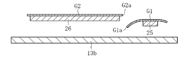
이렇게 하면, 상기 유효부는 횡반송부가 본래적으로 갖고 있는 반송력에 의해서 유리롤의 권취부측으로 이송되지만, 그 경우에 유리 필름 리본의 할단 직후에 있어서는 상기 유효부가 유효부 지지부에 의해서 지지되게 된다. 그리고, 유효부 지지부는 유효부를 그 폭 방향 양단부가 각각 폭 방향 외측으로 돌출된 상태에서 지지하는 것이기 때문에, 유효부는 유효부 지지부에 의해서 지지되고 있음에도 불구하고, 유효부의 할단 끝면의 끝가장자리는 유효부 지지부에 접하고 있지 않은 상태로 된다. 그 결과, 유효부의 할단 끝면은 유효부 지지부로부터의 외력의 영향을 직접적으로 받을 수 없게 되어서 유효부의 할단 끝면에는 그 끝가장자리와 유효부 지지부의 슬라이딩에 기인하는 크랙 등이 발생되지 않게 되어 상기 할단 끝면이 효과적으로 보호된다. 또한, 이 경우에 있어서의 유효부의 유효부 지지부로부터의 돌출 치수는 유효부의 폭 방향 양단부에 자중에 의한 처짐이 발생되지 않는 정도까지 짧아지는 것이 바람직하다. 또한, 유효부는 유효부 지지부에 의해서 면 접촉 지지되어 있는 것이 바람직하다.In this case, the effective portion is conveyed to the winding portion of the glass roll by the conveying force inherently possessed by the transverse conveying portion, but in this case, the effective portion is supported by the effective portion supporting portion immediately after the cutting of the glass film ribbon. Since the effective portion supporting portion supports the effective portion in a state where both end portions in the width direction protrude outward in the width direction, the effective edge portion is supported by the effective portion supporting portion, And is not in contact with the support portion. As a result, the end face of the effective portion can not receive the influence of the external force directly from the effective portion supporting portion, so cracks or the like caused by the sliding of the end edge and the effective portion supporting portion are not generated on the end face of the effective portion, Is effectively protected. In this case, it is preferable that the protruding dimension of the effective portion from the effective portion supporting portion in this case is shortened to the extent that deflection by self weight does not occur at both end portions in the width direction of the effective portion. It is preferable that the effective portion is surface-contact supported by the effective portion supporting portion.
이 경우, 상기 불요부 지지부에 의한 상기 불요부의 반송 궤도와 상기 유효부 지지부에 의한 상기 유효부의 반송 궤도는 반송 방향 하류측으로 이행함에 따라서 상하 방향으로 점차 확개되어 있는 것이 바람직하다.In this case, it is preferable that the conveying trajectory of the unnecessary portion by the unnecessary portion supporting portion and the conveying trajectory of the effective portion by the effective portion supporting portion gradually expand in the vertical direction as they move to the downstream side in the conveying direction.
이렇게 하면, 유효부와 불요부의 분리가 보다 한층 촉진될뿐만 아니라 불요부의 최종적인 폐기 처리 등을 행하는 점에서 유리해진다.This is advantageous in that not only the separation between the effective portion and the unnecessary portion is further promoted, but also the final disposal process of the unnecessary portion is performed.
이상의 구성에 있어서, 상기 불요부 지지부와 상기 유효부 지지부는 상기 횡반송부의 반송 경로를 따라서 정치로 설치된 정판의 반송 방향 하류단에 돌출될 수 있다.In the above configuration, the unnecessary portion supporter and the effective portion supporter may protrude from the downstream end of the top plate provided at the fixed position along the transport path of the transporter.
이렇게 하면, 정판 상에서 유리 필름 리본을 반송하면서 할단한 후, 유효부를 유효부 지지부에 의해서 지지시켜서 이송함과 아울러 불요부를 불요부 지지부에 의해서 지지시켜서 이송하는 것이 가능해진다. 그 결과, 유리 필름 리본의 할단으로부터 유효부 및 불요부의 이송에 이르는 일련의 동작이 원활하게 행해진다.In this case, after the glass ribbon is transported on the base plate, the effective portion is transported while being supported by the effective portion support, and the unnecessary portion can be transported while being supported by the unnecessary portion support. As a result, a series of operations from the cutting edge of the glass film ribbon to the conveyance of the effective portion and the unnecessary portion are smoothly performed.
이 경우, 상기 정판, 상기 불요부 지지부 및 상기 유효부 지지부와, 상기 유리 필름 리본 사이에 가요성을 갖는 반송용 시트 리본을 개재시키고, 상기 반송용 시트 리본의 하면이 상기 정판, 상기 불요부 지지부 및 상기 유효부 지지부와 슬라이딩하면서 이동함으로써 상기 반송용 시트 리본이 상기 유리 필름 리본을 반송하도록 해도 좋다.In this case, a conveying sheet ribbon having flexibility is interposed between the top plate, the sparse portion supporting portion and the effective portion supporting portion, and the glass film ribbon, and the lower surface of the conveying sheet ribbon is supported by the top plate, And the conveying sheet ribbon may be moved while sliding on the effective portion supporting portion to convey the glass film ribbon.
이렇게 하면, 유리 필름 리본(할단 후의 불요부 및 유효부를 포함함)과, 정판, 불요부 지지부 및 유효부 지지부가 접촉해서 슬라이딩하지 않게 되기 때문에, 유리 필름 리본에 손상이 가해지거나 또는 파손되거나 등의 문제가 회피됨과 아울러 유리 필름 리본의 반송이 원활하게 행해질 수 있다.In this case, since the glass film ribbon (including the unnecessary portions after the dressing and the effective portion) and the top plate, the unnecessary portion supporting portion and the effective portion supporting portion are prevented from sliding in contact with each other, the glass film ribbon is damaged or broken, The problem can be avoided and the conveying of the glass film ribbon can be performed smoothly.
또한, 상기 제 2 과제를 해결하기 위해서 창안된 본 발명에 의한 장치는, 유리 필름 리본을 횡반송부에 의해 횡방향으로 반송하면서, 상기 횡반송부의 반송 경로 상에 배치된 할단부에 의해 상기 유리 필름 리본을 폭 방향의 적어도 일단측의 불요부와 그 폭 방향 중앙측의 유효부의 경계선을 이루는 할단 예정선을 따라서 할단하도록 구성한 유리 필름 리본 제조 장치에 있어서, 상기 할단부에 의해 상기 유리 필름 리본이 할단된 후에, 상기 불요부가 상기 유효부와의 사이에 폭 방향 간극을 갖는 불요부 지지부에 의해서 지지되도록 구성한 것에 특징이 있다.In order to solve the second problem, an apparatus according to the present invention, which is invented to solve the second problem, is characterized in that while the glass film ribbon is transported in the transverse direction by the transverse transport section, The film ribbon is configured to be cut along a dividing line to form a boundary line between a useless portion at least at one end in the width direction and a usable portion at the center in the width direction, And the unnecessary portion is supported by the unnecessary portion supporting portion having a widthwise gap between the unnecessary portion and the effective portion.
이러한 구성을 구비한 장치에 의하면, 이미 설명한 대응하는 본 발명에 의한 방법과 마찬가지의 작용 효과를 얻을 수 있다.According to the apparatus having such a configuration, it is possible to obtain the same operational effects as those of the previously described method of the present invention.
(발명의 효과) (Effects of the Invention)
이상과 같이 제 1 과제를 해결하기 위해서 창안된 본 발명에 의하면, 장치의 횡반송부에 의해 횡방향으로 반송되고 있는 유리 필름 리본에 발생되는 주름에 의한 할단부에서의 할단 불량을 확실하게 억제하는 것이 가능해진다. 또한, 제 2 과제를 해결하기 위해서 창안된 본 발명에 의하면, 유리 필름 리본이 횡반송부에 의해 횡방향으로 반송되면서 불요부와 유효부로 할단된 후, 불요부의 지지가 적절화되어서 상기 불요부와 유효부의 할단 끝면끼리의 간섭이 가급적으로 억제된다.As described above, according to the present invention, which is intended to solve the first problem, it is possible to reliably suppress the detachment failure in the rear end portion due to the wrinkles generated in the glass film ribbon being transported in the lateral direction by the lateral transportation portion of the apparatus Lt; / RTI > In addition, according to the present invention developed to solve the second problem, after the glass film ribbon is conveyed in the lateral direction by the transverse conveying section, the unnecessary portion and the effective portion are cut off and the support of the unnecessary portion is made appropriate, The interference between the cut end faces of the effective portion is suppressed as much as possible.
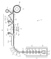
도 1은 본 발명의 제 1 실시형태에 의한 유리 필름 리본 제조 장치의 전체 구성을 나타내는 개략 측면도이다.
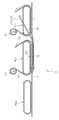
도 2는 본 발명의 제 1 실시형태에 의한 유리 필름 리본 제조 장치의 요부를 나타내는 확대 종단 측면도이다.
도 3은 본 발명의 제 1 실시형태에 의한 유리 필름 리본 제조 장치의 요부를 나타내는 확대 평면도이다.
도 4는 본 발명의 제 1 실시형태에 의한 유리 필름 리본 제조 장치의 요부를 나타내는 확대 종단 측면도이다.
도 5는 본 발명의 제 1 실시형태에 의한 유리 필름 리본 제조 장치의 요부를 나타내는 확대 종단 측면도이다.
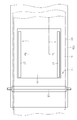
도 6은 본 발명의 제 1 실시형태에 의한 유리 필름 리본 제조 장치의 요부를 나타내는 확대 종단 정면도이다.
도 7은 본 발명의 제 1 실시형태에 의한 유리 필름 리본 제조 장치의 작용을 나타내는 확대 평면도이다.
도 8은 본 발명의 제 1 실시형태에 의한 유리 필름 리본 제조 장치의 작용을 나타내는 확대 평면도이다.
도 9는 본 발명의 제 1 실시형태에 의한 유리 필름 리본 제조 장치의 작용을 나타내는 확대 종단 정면도이다.
도 10은 본 발명의 제 1 실시형태에 의한 유리 필름 리본 제조 장치를 사용하여 제작된 유리롤의 개략 사시도이다.
도 11은 본 발명의 제 2 실시형태에 의한 유리 필름 리본 제조 장치의 요부를 나타내는 확대 평면도이다.
도 12는 본 발명의 제 2 실시형태에 의한 유리 필름 리본 제조 장치의 요부를 나타내는 확대 종단 정면도이다.
도 13은 본 발명의 제 2 실시형태에 의한 유리 필름 리본 제조 장치의 변형예의 요부를 나타내는 확대 평면도이다.
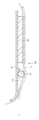
도 14는 본 발명의 제 3 실시형태에 의한 유리 필름 리본 제조 장치의 요부 구성을 나타내는 개략 측면도이다.
도 15는 본 발명의 제 4 실시형태에 의한 유리 필름 리본 제조 장치의 전체 구성을 나타내는 개략 측면도이다.
도 16은 본 발명의 제 5 실시형태에 의한 유리 필름 리본 제조 장치의 전체 구성을 나타내는 개략 측면도이다.
도 17은 본 발명의 제 5 실시형태에 의한 유리 필름 리본 제조 장치의 요부를 나타내는 확대 종단 측면도이다.
도 18은 본 발명의 제 5 실시형태에 의한 유리 필름 리본 제조 장치의 요부를 나타내는 확대 평면도이다.
도 19는 본 발명의 제 5 실시형태에 의한 유리 필름 리본 제조 장치의 요부를 나타내는 확대 측면도이다.
도 20은 본 발명의 제 5 실시형태에 의한 유리 필름 리본 제조 장치의 요부를 나타내는 확대 평면도이다.
도 21은 본 발명의 제 5 실시형태에 의한 유리 필름 리본 제조 장치의 요부를 나타내는 확대 측면도이다.
도 22는 도 21의 I-I선에 따라서 절단한 확대 종단면도이다.
도 23은 본 발명의 제 6 실시형태에 의한 유리 필름 리본 제조 장치의 요부를 나타내는 확대 측면도이다.
도 24는 본 발명의 제 6 실시형태에 의한 유리 필름 리본 제조 장치의 요부를 나타내는 확대 종단면도이다.
도 25는 본 발명의 제 7 실시형태에 의한 유리 필름 리본 제조 장치의 요부 구성을 나타내는 확대 종단면도이다.
도 26은 본 발명의 제 8 실시형태에 의한 유리 필름 리본 제조 장치의 요부 구성을 나타내는 확대 종단면도이다.
도 27은 본 발명의 제 9 실시형태에 의한 유리 필름 리본 제조 장치의 전체 구성을 나타내는 개략 측면도이다.
도 28a는 본 발명의 제 9 실시형태에 의한 유리 필름 리본 제조 장치의 요부의 일례를 나타내는 확대 종단면도이다.
도 28b는 본 발명의 제 9 실시형태에 의한 유리 필름 리본 제조 장치의 요부의 다른 예를 나타내는 확대 종단면도이다.BRIEF DESCRIPTION OF DRAWINGS FIG. 1 is a schematic side view showing the entire configuration of a glass film ribbon producing apparatus according to a first embodiment of the present invention; FIG.
2 is an enlarged longitudinal sectional side view showing a main part of a glass film ribbon producing apparatus according to a first embodiment of the present invention.
3 is an enlarged plan view showing a main part of a glass ribbon manufacturing apparatus according to a first embodiment of the present invention.
4 is an enlarged longitudinal sectional side view showing a main part of a glass film ribbon producing apparatus according to a first embodiment of the present invention.
5 is an enlarged longitudinal sectional side view showing a main part of a glass film ribbon producing apparatus according to a first embodiment of the present invention.
Fig. 6 is an enlarged longitudinal elevation view showing the essential part of the apparatus for manufacturing a glass film ribbon according to the first embodiment of the present invention. Fig.
7 is an enlarged plan view showing the operation of the apparatus for manufacturing a glass film ribbon according to the first embodiment of the present invention.
8 is an enlarged plan view showing the operation of the apparatus for manufacturing a glass film ribbon according to the first embodiment of the present invention.
9 is an enlarged longitudinal elevational view showing the operation of the apparatus for manufacturing a glass film ribbon according to the first embodiment of the present invention.
10 is a schematic perspective view of a glass roll manufactured using the apparatus for manufacturing a glass film ribbon according to the first embodiment of the present invention.
11 is an enlarged plan view showing a main part of a glass film ribbon producing apparatus according to a second embodiment of the present invention.
12 is an enlarged longitudinal elevation view showing a main part of a glass film ribbon producing apparatus according to a second embodiment of the present invention.
13 is an enlarged plan view showing a main part of a modification of the apparatus for manufacturing a glass film ribbon according to the second embodiment of the present invention.
Fig. 14 is a schematic side view showing the essential structure of a glass film ribbon producing apparatus according to a third embodiment of the present invention. Fig.
15 is a schematic side view showing the entire configuration of a glass film ribbon producing apparatus according to a fourth embodiment of the present invention.
16 is a schematic side view showing the entire configuration of a glass film ribbon producing apparatus according to a fifth embodiment of the present invention.
17 is an enlarged longitudinal side view showing a main part of a glass film ribbon producing apparatus according to a fifth embodiment of the present invention.
18 is an enlarged plan view showing a main part of a glass film ribbon producing apparatus according to a fifth embodiment of the present invention.
19 is an enlarged side view showing a main part of a glass film ribbon producing apparatus according to a fifth embodiment of the present invention.
20 is an enlarged plan view showing a main part of a glass film ribbon producing apparatus according to a fifth embodiment of the present invention.
21 is an enlarged side view showing a main part of a glass film ribbon producing apparatus according to a fifth embodiment of the present invention.
22 is an enlarged longitudinal sectional view cut along the line II in Fig.
23 is an enlarged side view showing a main part of a glass film ribbon producing apparatus according to a sixth embodiment of the present invention.
24 is an enlarged longitudinal sectional view showing a main part of a glass film ribbon producing apparatus according to a sixth embodiment of the present invention.
Fig. 25 is an enlarged longitudinal sectional view showing the essential structure of a glass film ribbon producing apparatus according to a seventh embodiment of the present invention. Fig.
Fig. 26 is an enlarged longitudinal sectional view showing the essential part of a glass film ribbon producing apparatus according to an eighth embodiment of the present invention. Fig.
27 is a schematic side view showing the entire configuration of a glass film ribbon producing apparatus according to a ninth embodiment of the present invention.
28A is an enlarged longitudinal sectional view showing an example of a main portion of a glass film ribbon producing apparatus according to a ninth embodiment of the present invention.
Fig. 28B is an enlarged longitudinal sectional view showing another example of a principal part of a glass film ribbon producing apparatus according to a ninth embodiment of the present invention. Fig.
이하, 본 발명의 실시형태에 의한 유리 필름 리본 제조 장치(이하, 단지 제조 장치라고 함) 및 유리 필름 제조 방법에 대하여 도면을 참조하면서 설명한다.DESCRIPTION OF THE PREFERRED EMBODIMENTS Hereinafter, a glass ribbon manufacturing apparatus (hereinafter simply referred to as a manufacturing apparatus) and a glass film manufacturing method according to an embodiment of the present invention will be described with reference to the drawings.
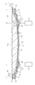
도 1은 본 발명의 제 1 실시형태에 의한 제조 장치(1)의 전체 구성을 모식적으로 나타내는 개략 측면도이다. 동 도면에 나타내는 바와 같이, 이 제조 장치(1)는 주된 구성 요소로서 유리 필름 리본(G)을 성형하는 성형부(2)와, 유리 필름 리본(G)의 진행 방향을 종방향 하방으로부터 횡방향으로 변환하는 방향 변환부(3)와, 방향 변환 후에 유리 필름 리본(G)을 횡방향으로 반송하는 횡반송부(4)와, 횡반송부(4)에 의해 횡방향으로 반송하고 있는 유리 필름 리본(G)의 핸들부(Gx)를 포함하는 불요부(G1)를 할단하는 할단부(5)와, 할단부(5)에 의해 불요부(G1)를 할단 제거해서 얻어진 유리 필름 리본(G)의 유효부(G2)를 롤 형상으로 권취해서 유리롤(R)을 제작하는 권취부(6)를 갖는다. 또한, 유리 필름 리본(G)의 유효부(G2)의 두께는 300㎛ 이하 또는 200㎛ 이하 또는 100㎛ 이하인 것이 바람직하다.Fig. 1 is a schematic side view schematically showing an overall configuration of a
성형부(2)는 상단부에 오버플로우 홈(7a)이 형성된 단면이 대략 쐐기형인 성형체(7)와, 성형체(7)의 바로 아래에 배치되어서 리본 형상의 용융 유리(Gb)를 표리 양측으로부터 끼우는 냉각 롤러(8)와, 냉각 롤러(8)의 바로 아래에 배치되어서 상하 방향 복수단으로 설치된 어닐러 롤러(9)를 갖는 어닐러(10)로 구성되어 있다. 상세하게 설명하면, 성형부(2)의 작용에 착안한 경우의 주성형부(2a)는 오버플로우 홈(7a)의 상방으로부터 흘러넘친 용융 유리(Ga)를 양측면을 따라서 각각 유하(流下)시키고, 하단에서 합류시켜서 리본 형상의 용융 유리(Gb)로 하는 성형체(7)와, 리본 형상의 용융 유리(Gb)의 폭 방향 수축을 규제하여 소정 폭의 유리 필름 리본(G)으로 하는 냉각 롤러(8)로 구성된다. 그리고, 이 주성형부(2a)의 하방으로 유리 필름 리본(G)에 대하여 왜곡 제거 처리를 실시하기 위한 어닐러(10)를 배치함으로써 상기 성형부(2)가 구성되어 있다.The
어닐러(10)의 하방에는 유리 필름 리본(G)을 표리 양측으로부터 협지하는 인장 롤러(11)가 배치되고, 인장 롤러(11)와 냉각 롤러(8) 사이, 또는 인장 롤러(11)와 어느 1개소의 어닐러 롤러(9) 사이에서 유리 필름 리본(0G)을 박육으로 하는 것을 조장하기 위한 장력이 부여되어 있다. 또한, 이 인장 롤러(11)는 유리 필름 리본(G)의 두께가 큰 경우에는 유리 필름 리본(G)의 자중에 의한 하방으로의 연장을 방지하는 지지 롤러로서의 역할을 한다.A
인장 롤러(11)의 하방에는 유리 필름 리본(G)의 진행 방향을 종방향 하방으로부터 횡방향으로 변환하는 방향 변환부(3)가 구비되어 있다. 이 방향 변환부(3)에는 유리 필름 리본(G)의 이면측에 유리 필름 리본(G)의 방향 전환을 안내하는 가이드 부재로서의 복수의 가이드 롤러(12)가 만곡 형상으로 배열되고, 이들 가이드 롤러(12)는 유리 필름 리본(G)의 이면에 접촉하고 있다. 또한, 이들 가이드 롤러(12)는 유리 필름 리본(G)의 이면에 대하여 기류 등을 분사함으로써 유리 필름 리본(G)을 비접촉으로 지지하는 것이어도 좋다. 또한, 가이드 부재로서는 만곡 형상으로 형성된 벨트 컨베이어 형상의 형태를 이루는 한 개의 것이어도 좋고, 또는 방향 변환부(3)에 가이드 부재를 설치하지 않고 유리 필름 리본(G)이 이면측으로부터의 외력의 영향을 받는 일 없이 방향 변환하도록 해도 좋다. 또한, 복수의 가이드 롤러(12) 중 일부의 가이드 롤러(12)가 유리 필름 리본(G)의 이면과 접촉하고 있어도 좋다. 또한, 가이드 롤러(12)는 유리 필름 리본(G)의 일부(예를 들면, 폭 방향 양단부)만을 지지하고 있어도 좋다.Below the
방향 변환부(3)의 반송 경로에 있어서의 하류측에는 유리 필름 리본(G)을 횡방향으로 반송하는 횡반송부(4)가 구비되어 있다. 이 횡반송부(4)에는 반송 방향에 직렬로 3대의 벨트 컨베이어(13a, 13b, 13c)가 배열되어 있다. 상세하게 설명하면, 횡반송부(4)에는 상시 정지하고 있는 정지 컨베이어(13b)와, 정지 컨베이어(13b)의 상류측이고 방향 변환부(3)에 이르기까지의 위치에 배열되고 또한 선회 구동하는 제 1 구동 컨베이어(13a)와, 정지 컨베이어(13b)의 하류측이고 권취부(6)에 이르기까지의 위치에 배열되고 또한 선회 구동하는 제 2 구동 컨베이어(13c)가 배열되어 있다. 따라서, 방향 변환부(3)와 권취부(6) 사이에 있어서는 상류측으로부터 순서대로 반송 수단으로서의 제 1 구동 컨베이어(13a)와, 정치로 구동 불가능하게 설치된 정지 컨베이어(13b)와, 반송 수단으로서의 제 2 구동 컨베이어(13c)가 각각 인접해서 배열되어 있다. 또한, 본 실시형태에서는 횡반송부(4)가 유리 필름 리본(G)(할단 후의 유효부(G2)를 포함함)을 수평 방향으로 반송하도록 구성되어 있지만, 수평 방향에 대하여 상하로 각각 45° 미만의 범위 내(바람직하게는 30° 미만의 범위 내)에서 경사지고 있어도 좋다.On the downstream side in the conveying path of the
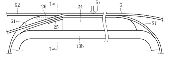
횡반송부(4)에 있어서의 정지 컨베이어(13b)의 상부에는 유리 필름 리본(G)에 발생된 주름을 제거하는 주름 제거 수단(14)이 정치로 설치되어 있다. 이 주름 제거 수단(14)과 유리 필름 리본(G) 사이에는 발포 수지로 이루어지는 신축성을 갖는 반송용 시트 리본(S1)이 개재되어 있다. 이 반송용 시트 리본(S1)은 하면이 주름 제거 수단(14)에 슬라이딩 가능하게 됨과 아울러 상면이 유리 필름 리본(G)을 반송 지지하는 반송 지지면으로 되어 있다. 또한, 정지 컨베이어(13b)의 상부에 있어서의 반송 경로 중앙부의 상방에는 유리 필름 리본(G)의 폭 방향(표리면을 따르는 방향이고 또한 반송 방향과 직교하는 방향)의 양단부에 형성되는 후육의 핸들부(Gx)를 포함하는 불요부(G1)를 할단하는 할단부(5)가 배치되어 있다. 즉, 정지 컨베이어(13b)는 그 반송 경로 상에 유리 필름 리본(G)의 불요부(G1)를 할단하는 할단부(5)를 갖고 있다. 상세하게 설명하면, 이 할단부(5)에는 유리 필름 리본(G)의 불요부(G1)와 그 폭 방향 중앙측의 박육의 유효부(G2)의 경계(도 3에 나타내는 길이 방향으로 연장되는 할단 예정선(A))에 대하여 국부 가열을 행하는 레이저광 조사 수단(5aa)과, 레이저광 조사 수단(5aa)에 의한 가열 부위에 대하여 냉각을 행하는 미스트수 분사 수단(5ab)으로 이루어지는 열응력 할단 장치(5a)가 설치되어 있다. 그리고, 할단된 불요부(G1)(엄밀하게는 핸들부(Gx)를 포함하는 불요부(G1))는 반송 방향 전방에 대해 비스듬히 하방을 향해서 이송되어서 파기되도록 되어 있다.A wrinkle removing means 14 for removing the wrinkles generated in the glass film ribbon G is provided at the upper portion of the
횡반송부(4)의 하류측에는 핸들부(Gx)를 포함하는 불요부(G1)가 제거되어서 반송되어 온 유리 필름 리본(G)(유효부(G2))을 권취해서 유리롤(R)로 하는 권취부(6)가 배치되어 있다. 이 권취부(6)의 하방에는 보호 시트(S)를 권회해서 이루어지는 시트롤(r)이 배치되어 있으며, 이 시트롤(r)로부터 인출된 보호 시트(S)가 권취부(6)에 의해 유리 필름 리본(G)(유효부(G2))에 겹쳐져서 권취되어 감에 따라서 유리롤(R)이 제작되도록 되어 있다.A glass film ribbon G (effective portion G2) which has been conveyed after the unnecessary portion G1 including the handle portion Gx is removed is wound on the downstream side of the transverse conveying
도 2는 횡반송부(4)의 구성을 상세하게 나타내는 확대 종단 측면도이다. 동 도면에 나타내는 바와 같이, 반송용 시트 리본(S1)은 정지 컨베이어(13b)의 하방에 배치되어 있는 시트롤(r1)로부터 상방을 향해서 인출되고, 정지 컨베이어(13b)의 상부에서 주름 제거 수단(14)과 유리 필름 리본(G) 사이를 통과하여 정지 컨베이어(13b)의 하류측 단부로부터 하방을 향해서 송출되도록 되어 있다. 이 경우, 반송용 시트 리본(S1)은 도면 밖의 구동 수단에 의해서 주름 제거 수단(14)과 슬라이딩하면서 개방 루프 형상(또는 도시하지 않지만 폐쇄 루프 형상)으로 이송되는 구성으로 되어 있다. 이 시트 리본(S1)을 형성하는 발포 수지는 폴리에틸렌이나 폴리프로필렌 등의 수지로 이루어지고, 발포 배율이 5배~100배이며, 두께가 0.1~3.0㎜로 되어 있다. 이와 같은 구성에 의하면, 성형부(2)로부터 방향 변환부(3)를 거쳐 횡반송부(4)에 이른 유리 필름 리본(G)은 제 1 구동 컨베이어(13a)의 상면부로부터 반송용 시트 리본(S1)의 상면부로 갈아타서 반송되게 된다.2 is an enlarged longitudinal sectional side view showing the configuration of the
또한, 제 2 구동 컨베이어(13c)의 상면부에는 발포 수지로 이루어지는 신축성을 갖는 시트 리본(S2)이 겹쳐서 권취되어 있으며, 이 시트 리본(S2)의 상면이 핸들부(Gx)를 포함하는 불요부(G1)의 할단 제거 후에 있어서의 유리 필름 리본(G)의 유효부(G2)를 반송 지지하는 반송 지지면으로 되어 있다. 이 제 2 구동 컨베이어(13c)의 하방에는 시트 리본(S2)을 권회해서 이루어지는 시트롤(r2)이 배치되어 있으며, 이 시트롤(r2)로부터 상방을 향하여 인출된 시트 리본(S2)이 제 2 구동 컨베이어(13c)의 상류측 단부로부터 벨트의 상면부에 겹쳐서 권취되어 또한 제 2 구동 컨베이어(13c)의 하류측 단부로부터 하방을 향해서 송출되도록 되어 있다. 따라서, 이 시트 리본(S2)은 제 2 구동 컨베이어(13c)의 벨트의 상면부를 추종해서 개방 루프 형상(또는 도시하지 않지만 폐쇄 루프 형상)으로 이송되는 구성으로 되어 있다. 또한, 이 시트 리본(S2)을 형성하는 발포 수지는 폴리프로필렌이나 폴리에틸렌 등의 수지로 이루어지고, 발포 배율이 5배~100배이며, 두께가 0.1~3.0㎜로 되어 있다.The upper surface of the
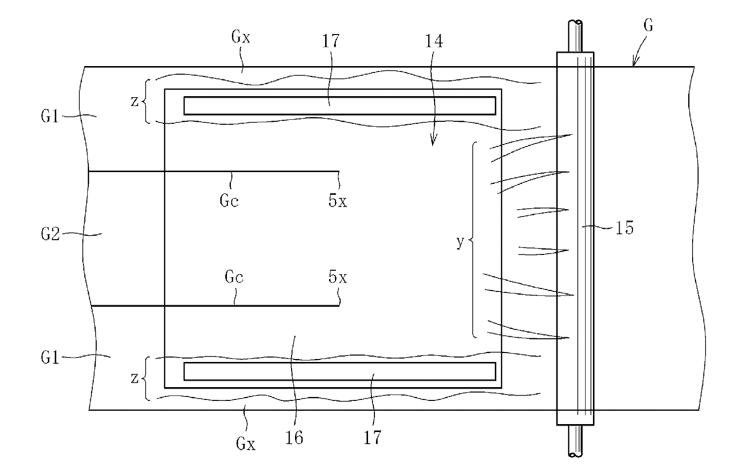
도 3은 주름 제거 수단(14)의 전체 구성을 나타내는 평면도이다. 동 도면에 나타내는 바와 같이, 주름 제거 수단(14)은 유리 필름(G)에 대한 할단부(5)에 의한 할단 위치(5x)보다 상류측에 배치되고 또한 반송 방향과 직교하는 방향으로 연장되는 직교 막대 형상체(15)와, 할단 위치(5x)의 상류측으로부터 하류측에 걸쳐서 배치되고 또한 평면으로 볼 때 직사각형인 베이스 플레이트(16)와, 베이스 플레이트(16)의 폭 방향(반송 방향과 직교하는 방향)에 있어서의 양단부에 각각 배치되고 또한 반송 방향과 평행한 방향으로 연장되는 한 쌍의 평행 막대 형상체(17)를 갖는다. 또한, 동 도면으로부터 파악할 수 있는 바와 같이 반송용 시트 리본(S1)의 폭 방향 양단은 유리 필름 리본(G)의 폭 방향 양단으로부터 돌출되어 있음과 아울러, 정지 컨베이어(13b)의 폭 방향 양단은 반송용 시트 리본(S1)의 폭 방향 양단으로부터 돌출되어 있다. 이 경우, 도시예에서는 직교 막대 형상체(15)의 길이 방향 양단이 유리 필름 리본(G)의 폭 방향 양단으로부터 돌출되어 있지만, 이것과는 반대로 유리 필름 리본(G)의 폭 방향 양단이 직교 막대 형상체(15)의 길이 방향 양단으로부터 돌출되어 있어도 좋다. 또한, 도시예에서는 반송용 시트 리본(S1)의 폭 방향 양단이 유리 필름 리본(G)의 폭 방향 양단으로부터 돌출되어 있지만, 이것과는 반대로 유리 필름 리본(G)의 폭 방향 양단이 반송용 시트 리본(S1)의 폭 방향 양단으로부터 돌출되어 있어도 좋다.3 is a plan view showing the entire configuration of the
주름 제거 수단(14)을 구성하고 있는 직교 막대 형상체(15)는, 도 4에 나타내는 바와 같이 정지 컨베이어(13b)의 상류측 단부에 배치되고, 길이 방향으로 직각인 단면의 형상이 원형을 이룸과 아울러, 예를 들면 정지 컨베이어(13b)에 고정됨으로써 회전 불능인 상태에서 정치로 설치되어 있다. 또한, 이 직교 막대 형상체(15)는 단면 형상이 원형이 아니어도 좋고, 예를 들면 타원형이거나, 또는 다각형이거나, 또는 하면부가 평탄면 등이어도 좋고, 어느 쪽이든 유리 필름 리본(G)의 하면측과 접촉하는 면(상면)이 볼록 형상으로 만곡 또는 돌출되어 있으면 좋다. 또한, 이 직교 막대 형상체(15)는 상기 단면 형상이 원형인 경우에는 정지 컨베이어(13b)의 상면으로부터 상방으로 이간시킨 상태에서 화살표 a 방향(유리 필름 리본(G)의 반송 방향을 따르는 방향)으로 회전 구동하는 구성으로 되어 있어도 좋다. 그 경우, 직교 막대 형상체(15)의 둘레 속도는 유리 필름 리본(G)의 반송 속도와 동일 또는 그것보다 저속으로 된다. 또한, 이러한 경우에는 직교 막대 형상체(15)가 공전하도록 유지되어 있어도 좋다.As shown in Fig. 4, the orthogonal bar-
이 직교 막대 형상체(15)의 상단 위치는, 도 5에 나타내는 바와 같이 베이스 플레이트(16)의 상단 위치보다 높아지도록 설정되어 있으며, 그 높이의 상위 치수(h)는 1㎜~10㎜, 바람직하게는 1~3㎜, 이 실시형태에서는 2㎜로 되어 있다. 이 경우, 직교 막대 형상체(15)와 베이스 플레이트(16)는 근접한 상태에서 이간하고 있지만, 그 이간 치수는 유리 필름 리본(G)이 직교 막대 형상체(15)로부터 베이스 플레이트(16)로 갈아탈 때에 굴곡되지 않고 매끄럽게 만곡될 정도이면 좋고, 또는 직교 막대 형상체(15)와 베이스 플레이트(16)가 접촉 또는 대략 접촉되어 있어도 좋다.As shown in Fig. 5, the upper end position of the orthogonal bar-
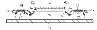
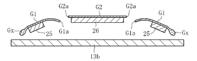
주름 제거 수단(14)을 구성하고 있는 베이스 플레이트(16)는, 도 6에 나타내는 바와 같이 예를 들면 정지 컨베이어(13b)의 상면부에 고정 설치되고, 그 상면(16a)은 폭 방향 중앙부가 폭 방향 양단부보다 높아지도록 완만하게 만곡되어 있다. 이 경우, 베이스 플레이트(16)의 도시 단면 형상은, 예를 들면 중앙부가 평탄하고 또한 양단부가 경사지는 사다리꼴 형상 등이어도 좋다. 그리고, 유리 필름 리본(G)의 폭 방향 양단부의 핸들부(Gx)는 유효부(G2)보다 두꺼움과 아울러, 이들 핸들부(Gx)는 베이스 플레이트(16)의 상면에 있어서의 폭 방향 양단으로부터 각각 돌출되어서 뜬 상태로 되어 있다. 상세하게는, 유리 필름 리본(G)은 반송용 시트 리본(S1)을 개재해서 베이스 플레이트(16)의 상면에 의해 하방으로부터 지지된 상태에서, 그 핸들부(Gx)를 포함하는 양단부가 베이스 플레이트(16)의 폭 방향 양단으로부터 돌출되어 반송용 시트 리본(S1)의 양단부의 상방에서 뜬 상태로 되어 있다.6, the
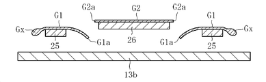
주름 제거 수단(14)을 구성하고 있는 평행 막대 형상체(17)는 베이스 플레이트(16)의 폭 방향 양단으로부터 약간 중앙부 근처 위치의 상면부에 각각 고정 설치되고, 그것들의 평행 막대 형상체(17)의 상단부는 베이스 플레이트(16)의 상면으로부터 상방으로 돌출되어 있다. 또한, 평행 막대 형상체(17)의 유리 필름 리본(G)의 하면측과 접촉하는 면(상면)은 볼록 형상으로 만곡하고, 그 하면부는 평탄면으로 되어 있지만, 이 평행 막대 형상체(17)의 길이 방향과 직교하는 단면의 형상은 원형, 타원형, 정사각형 또는 직사각형 등이어도 좋다. 또한, 이 평행 막대 형상체(17)의 길이 방향 양단은 베이스 플레이트(16)의 대응하는 양단보다 약간 길이 방향 중앙 근처 위치에 존재하고 있다.The parallel bar-shaped
이상과 같은 구성에 의하면, 도 1에 나타내는 성형부(2)로부터 방향 변환부(3)를 거쳐 횡반송부(4)에 이른 유리 필름 리본(G)은, 박육이며 가요성을 갖고 있는 것에 기인하여 제 1 구동 컨베이어(13a)에 의해서 횡방향으로 반송되는 동안에 광범위에 걸쳐서 주름이 발생된다. 그러나, 이 제 1 구동 컨베이어(13a)의 상면부에서 발생된 주름은 그 하류측에 설치되어 있는 주름 제거 수단(14)에 의해서 적정하게 제거되어 할단부(5)에 의한 할단 영역 주변에서는 레이저 할단에 지장이 생기지 않는 정도까지 소실된다.According to the above-described structure, the glass film ribbon G which has been passed from the forming
도 7은 주름 제거 수단(14)의 구성 요소인 직교 막대 형상체(15)만에 의한 작용 효과를 나타내는 개략 평면도이며, 편의상 반송용 시트 리본 및 각 컨베이어의 도시를 생략하고 있다. 동 도면에 나타내는 바와 같이, 제 1 구동 컨베이어(13a)의 상면부에서는 유리 필름 리본(G)에 부호 X로 나타내는 바와 같은 다양한 방향성을 가진 불규칙한 주름이 폭 방향의 전 영역에 발생되어 있다. 이 유리 필름 리본(G)이 정지 컨베이어(13b)의 상면부에 이른 후에 있어서, 직교 막대 형상체(15)에 올라탄 경우에는 직교 막대 형상체(15)의 하류측 부위에 부호 Y로 나타내는 바와 같은 반송 방향을 따르는 주름이 폭 방향 중앙부에 발생됨과 아울러, 부호 Z로 나타내는 바와 같은 반송 방향과 직교하는 방향을 따르는 주름이 폭 방향 양단부에 발생된다. 즉, 부호 X로 나타내는 바와 같은 폭 방향의 전 영역에 발생되어 있던 불규칙한 주름은 유리 필름 리본(G)을 직교 막대 형상체(15)가 들어올림으로써 부호 Y, Z로 나타내는 바와 같은 부분적으로 규칙적인 주름으로 변환된다. 따라서, 이 직교 막대 형상체(15)만으로도 할단 부위(5x)에서의 레이저 할단에 대한 주름의 악영향은 완화된다. 또한, 부호 Z로 나타내는 주름은 유리 필름 리본(G)의 폭 방향 양단부에 존재하는 핸들부(Gx)의 두께에 편차가 있기 때문에 폭 방향 양단부에 있어서는 반송 방향에 대하여 요철이 존재하는 것으로부터 유래되어 발생된 것이다.Fig. 7 is a schematic plan view showing the action and effect of only the orthogonal bar-shaped
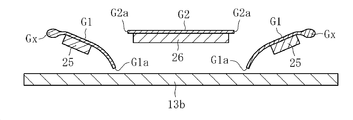
도 8은 주름 제거 수단(14)으로서, 상기 직교 막대 형상체(15)에 추가하여 베이스 플레이트(16)와, 한 쌍의 평행 막대 형상체(17)를 배치한 경우의 작용 효과를 나타내는 개략 평면도이고, 편의상 반송용 시트 리본 및 각 컨베이어의 도시를 생략하고 있다. 동 도면에 나타내는 바와 같이, 유리 필름 리본(G)이 직교 막대 형상체(15)에 올라탄 후, 또한 베이스 플레이트(16) 및 한 쌍의 평행 막대 형상체(17)에 올라탄 경우에는 이미 설명한 부호 Y로 나타낸 반송 방향을 따르는 주름이 이 시점에서는 부호 y로 나타내는 바와 같이 매우 짧은 주름으로 됨과 아울러, 이미 설명한 부호 Z로 나타낸 반송 방향과 직교하는 방향을 따르는 주름이 이 시점에서는 부호 z로 나타내는 바와 같이 폭 방향 양단부에 있어서의 매우 좁은 폭 영역에서의 주름으로 변환된다. 이러한 현상이 생기는 제 1 요인은, 도 9에 나타내는 바와 같이 유리 필름 리본(G)의 핸들부(Gx)를 포함하는 폭 방향 양단부가 베이스 플레이트(16)의 폭 방향 양단(또는 한 쌍의 평행 막대 형상체(17))으로부터 돌출되어서 떠 있기 때문에, 이미 설명한 핸들부(Gx)에 있어서의 요철의 영향을 받지 않게 되는 것에 의한 것이다. 또한, 제 2 이유는 상기와 같이 핸들부(Gx)가 돌출되어서 떠 있는 것, 및 베이스 플레이트(16)의 상면의 폭 방향 중앙부가 폭 방향 양단부보다 높게 되어 있는 것의 상승 효과에 의해서 유리 필름 리본(G)에 화살표 D로 나타내는 폭 방향 외측을 향하는 인장력이 발생되는 것에 의한 것이다. 또한, 제 3 이유는 반송 방향을 따르도록 발생되어 있던 주름이 유리 필름 리본(G)의 폭 방향 양단부를 평행 막대 형상체(17)가 들어올림으로써 평행 막대 형상체(17)의 근방으로 끌어넣어지는 것에 의한 것이다. 따라서, 도 8에 나타내는 할단 위치(5x)에서는 주름의 영향을 거의 받는 일 없이 할단 부위(Gc)가 직선 형상으로 진행되어 나가게 된다. 그 결과, 할단 후에 있어서의 유리 필름 리본(G3)의 할단 끝면은 적정한 성상을 갖게 된다.8 is a schematic plan view showing an action effect when the
또한, 베이스 플레이트(16) 및 평행 막대 형상체(17)는 어느 것이라도, 할단 위치(5x)의 상류측으로부터 하류측에 걸쳐서 배치되어 있기 때문에, 할단이 행해진 후라도 할단 부위(Gc)에 여전히 들어올림력이 작용하거나, 또는 핸들부(Gx)를 포함하는 불요부(G1)에 폭 방향 양단측을 향하는 인장력이 여전히 작용하게 되기 때문에, 할단 부위(Gc)에 있어서의 대향하는 할단 끝면이 서로 이반되려고 한다. 그 때문에, 할단 부위(Gc)에 있어서의 대향하는 할단 끝면끼리가 접촉되는 것에 의한 손상이나 깨짐의 발생이 효과적으로 회피되어 적정한 성상의 할단 끝면을 확보하는 것이 가능해진다.Since both the
이상과 같이 해서 할단을 종료한 유리 필름 리본(G)은 주름이 소실된 상태에서 권취부(6)에 이름으로써, 최종적으로 도 10에 나타내는 바와 같이 권심(18)의 둘레에 유리 필름 리본(유효부(G2))과 보호 시트(S)가 겹쳐진 상태에서 권취되어서 이루어지는 유리롤(R)을 얻을 수 있다. 이렇게 해서 얻어진 유리롤(R)은 권취 어긋남이나 끝면의 손상 등이 매우 적은 고품질의 것으로 된다.The glass film ribbon G finished in the above-described manner is wound on the winding
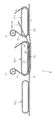
도 11은 본 발명의 제 2 실시형태에 의한 제조 장치(1)의 요부 구성을 나타내는 평면도이며, 도 12는 마찬가지로 상기 제조 장치(1)의 요부 구성을 나타내는 종단 정면도이다. 이들 각 도면에 나타내는 바와 같이, 이 제 2 실시형태에 의한 제조 장치(1)가 상술의 제 1 실시형태에 의한 제조 장치(1)와 상위하고 있는 점은, 할단 위치(5x)를 포함하고 또한 할단 위치(5x)로부터 상류측과 하류측을 향하는 영역에 배치되어서 반송 방향과 평행한 방향으로 연장되는 한 쌍의 인상체(20)가 주름 제거 수단(14)의 구성 요소로서 추가되어 있는 점과, 유리 필름 리본(G)의 폭 방향 양단부에 있어서의 핸들부(Gx)를 상방으로부터 누르는 한 쌍의 압박체(21)가 추가되어 있는 점이다. 그 밖의 구성 요소에 대해서는 상술의 제 1 실시형태와 동일하므로, 이하의 설명에 있어서 양 실시형태에 공통하는 구성 요소에 대해서는 동일 부호를 붙이고, 그 설명을 생략한다.Fig. 11 is a plan view showing a main part of a
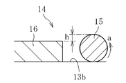
인상체(20)는 베이스 플레이트(16)의 상면부에 고정 설치되어서 베이스 플레이트(16)의 상면으로부터 상방으로 돌출됨과 아울러, 인상체(20)가 설치되어 있는 폭 방향 위치는 유리 필름 리본(G)의 할단 부위(Gc)와 할단 위치(5x)를 포함하는 위치로 되어 있다. 또한, 인상체(20)의 반송 방향을 따르는 길이는 베이스 플레이트(16)의 반송 방향을 따르는 길이와 동일 또는 대략 동일하게 되어 있다. 여기서, 도 11에 나타내는 할단 위치(5x)는 유리 필름 리본(G)이 실제로 할단되는 위치, 상세하게는 유리 필름 리본(G)이 할단되어 갈 때의 시단이 되는 위치여도 좋다.The pulling
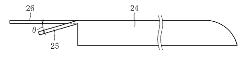
상기 구성에 대해서 상세하게 설명하면, 인상체(20)에 있어서의 베이스 플레이트(16)의 상면으로부터의 돌출 높이(t)는 {[0.05/유리 필름 리본(G)의 두께(㎜)](㎜)}에서 {[1.00/유리 필름 리본(G)의 두께(㎜)](㎜)}까지의 범위 내에 있는 것이 바람직하고, {[0.10/유리 필름 리본(G)의 두께(㎜)](㎜)}에서 {[0.75/유리 필름 리본(G)의 두께(㎜)](㎜)}까지의 범위 내에 있는 것이 보다 바람직하다. 이 돌출 높이(t)가 지나치게 높으면, 인상체(20)로부터 유리 필름 리본(G)에 작용하는 굽힘 응력이 커지고, 유리 필름 리본(G)의 할단 위치(5x)를 기점으로 해서 굽힘 응력을 따르는 깨짐이 상류측을 향해서 진전하여 레이저 할단을 할 수 없게 된다. 한편, 이 돌출 높이(t)가 지나치게 낮으면, 인상체(20)에 의한 유리 필름 리본(G)의 들어올림량이 부족하고, 특히 두께가 작은(예를 들면, 두께가 40㎛ 이하의) 유리 필름 리본(G)에 있어서의 주름 제거 효과를 충분히 얻을 수 없게 된다. 따라서, 이 돌출 높이(t)가 상기 범위 내이면, 이들 문제가 회피될 수 있다.The protrusion height t from the upper surface of the
인상체(20)의 폭(w1)은 유리 필름 리본(G)의 두께의 500배~10,000배의 범위 내에 있는 것이 바람직하고, 1,000배~5,000배의 범위 내에 있는 것이 보다 바람직하다. 이 폭(w1)이 지나치게 넓으면 인상체(20)가 유리 필름 리본(G)의 넓은 영역을 들어올리게 되기 때문에 충분한 당김을 갖게 하는 것이 곤란해져서 들어올림에 의한 효과를 얻을 수 없게 된다. 한편, 이 폭(w1)이 지나치게 좁으면 인상체(20)가 유리 필름 리본(G)을 들어올리는 영역이 부족해서 충분한 당김을 갖게 하는 것이 곤란해져서, 이 경우에도 들어올림에 의한 효과를 얻을 수 없게 된다. 따라서, 이 폭(w1)이 상기 범위 내이면, 이들 문제가 회피될 수 있다. 이 경우, 인상체(20)의 폭은 할단 위치(5x)의 상류측으로부터 하류측에 걸쳐서 일정해도 좋지만, 예를 들면 도 13에 나타내는 바와 같이 상류측으로부터 하류측으로 이행함에 따라서 점차 폭이 좁아지고 있어도 좋고, 또는 할단 위치(5x)를 경계로 해서 그 상류측의 일정 폭의 부위보다 하류측의 일정 폭의 부위 쪽이 좁게 되어 있어도 좋다. 또한, 인상체(20)는 그 폭 방향의 중심에 할단 위치(5x)가 존재하고 있어도 좋지만, 그 폭 방향의 중심이 할단 위치(5x)로부터 오프셋되어 있어도 좋고, 그 경우에는 그 폭 방향의 중심이 할단 위치(5x)로부터 폭 방향 외측으로 오프셋되어 있는 것이 바람직하다.The width w1 of the
인상체(20)의 길이는 할단 위치(5x)로부터 상류측을 향해서 100㎜ 이상인 것이 바람직하고, 200㎜ 이상인 것이 보다 바람직하고, 또한 할단 위치(5x)로부터 하류측을 향해서 100㎜ 이상인 것이 바람직하고, 200㎜ 이상인 것이 보다 바람직하다. 이 인상체(20)의 길이는 할단 위치(5x)의 상류측 부위 및 하류측 부위 중 어느 것에 대해서도, 지나치게 단척이면 유리 필름 리본(G)에 발생된 주름을 제거하는 효과가 충분하게 얻어지지 않게 된다.The length of the pulling
또한, 인상체(20)의 길이 방향과 직교하는 단면의 형상은 도 12에 나타내는 예와 같이 직사각형이어도 좋지만, 원형, 타원형 또는 정사각형 등이어도 좋고, 어느 쪽이든 유리 필름 리본(G)을 상방으로 볼록한 만곡 형상이 되도록 들어올릴 수 있으면 좋다.The shape of the cross section orthogonal to the longitudinal direction of the
한편, 압박체(21)는 유리 필름 리본(G)의 폭 방향 양단부에 있어서의 핸들부(Gx)가 존재하고 있는 폭 방향의 위치를 반송 방향과 평행한 방향으로 연장하고 있다. 이 압박체(21)는 바닥면이나 정지 컨베이어(13b) 등에 고정된 문형의 지주에 매달려 지지되어서 정치로 설치되고, 할단 위치(5x)의 상류측으로부터 하류측에 걸쳐서 설치되어 있다.On the other hand, the
이 압박체(21)의 역할은 다음에 나타내는 바와 같다. 즉, 유리 필름 리본(G)의 폭 방향 양단부에 있어서의 핸들부(Gx)에는 그 횡반송시에 상방으로 볼록하게 되는 부분과 하방으로 볼록하게 되는 부위가 길이 방향으로 인접해서 반복 형성되는 것이 통례이며, 반송에 수반하여 상방으로 볼록하게 되어 있던 부분이 하방으로 볼록하게 되는 부분으로 반전되거나, 하방으로 볼록하게 되어 있던 부분이 상방으로 볼록하게 되는 부분으로 반전되거나 하는 일이 빈번하게 발생되고 있었다. 이러한 사태가 생기면, 유리 필름 리본(G)의 핸들부(Gx)에 진동이 발생하고, 이 진동이 할단 위치(5x)에 전파되기 때문에 할단을 중지시키지 않을 수 없게 된다. 그러나, 압박체(21)가 설치되어 있으면 유리 필름 리본(G)의 핸들부(Gx)를 각각 압박체(21)가 상방으로부터 누름으로써 상방으로 볼록하게 되어 있는 부분 및 하방으로 볼록하게 되어 있는 부분이 반전하는 것을 방지한 상태에서 횡반송을 행하는 것이 가능해진다. 따라서, 상방으로 볼록하게 되는 부분과 하방으로 볼록하게 되는 부분이 반전한다고 하는 현상이 생길 수 없게 되고, 이것에 수반하여 진동의 발생이 억제되어 레이저 할단이 원활하고 또한 양호하게 행해진다.The function of this
압박체(21)의 하면이 유리 필름 리본(G)의 핸들부(Gx)의 상면에 접촉하고 있는 폭(이하, 압박폭이라고 함)의 치수(w2)는 유리 필름 리본(G)의 할단 위치(5x)에서 핸들부(Gx)의 폭 방향 외단까지의 치수(w3)의 0.01배~0.5배의 범위 내에 있는 것이 바람직하고, 0.05배~0.25배의 범위 내에 있는 것이 보다 바람직하다. 이 압박폭이 지나치게 좁으면, 압박체(21)의 하면이 핸들부(Gx)에 접촉하는 영역이 부족하기 때문에 핸들부(Gx)의 진동을 억지하는 효과를 충분히 얻을 수 없게 된다. 한편, 이 압박폭이 지나치게 넓으면, 압박체(21)가 핸들부(Gx)를 누름으로써 발생되는 응력이 유리 필름 리본(G)의 할단 위치(5x)에 도달하기 때문에 할단을 똑바로 진전시키는 것이 방해되어서 할단 정지의 요인이 된다. 따라서, 이 압박폭의 치수(w2)가 상기 범위 내에 있으면, 이들 문제가 회피될 수 있다.The dimension w2 of the width (hereinafter referred to as the pressing width) at which the lower surface of the
압박체(21)의 길이는 할단 위치(5x)로부터 상류측을 향해서 100㎜ 이상인 것이 바람직하고, 200㎜ 이상인 것이 보다 바람직하고, 또한 할단 위치(5x)로부터 하류측을 향해서 100㎜ 이상인 것이 바람직하고, 200㎜ 이상인 것이 보다 바람직하다. 이 압박체(21)의 길이는 할단 위치(5x)의 상류측 부위 및 하류측 부위의 어느 것에 대해서도, 지나치게 단척이면 핸들부(Gx)의 진동을 억지하는 효과가 불충분해진다. 또한, 도 11에 나타내는 예와 같이 압박체(21)에 있어서의 할단 위치(5x)의 상류측 부위의 길이는 하류측 부위의 길이보다 길게 되어 있어도 좋다.The length of the
압박체(21)의 하면은 유리 필름 리본(G)의 핸들부(Gx)가 처져 있는 방향을 따라서 경사져 있는 것이 바람직하고, 도 12에 나타내는 핸들부(Gx)의 처짐선(L)을 기준으로 해서 압박체(21)의 하면의 각도(α)가 ± 20° 이내에 포함되어 있는 것이 바람직하다. 압박체(21)의 하면의 수평면으로부터의 경사 각도가 지나치게 크면, 유리 필름 리본(G)의 핸들부(Gx)를 하방으로 압박하는 힘이 부족해지기 때문에 핸들부(Gx)의 진동을 억지하는 효과가 불충분해진다. 한편, 압박체(21)의 하면의 수평면으로부터의 경사 각도가 지나치게 작으면, 핸들부(Gx)의 상면에 대한 압박체(21)의 하면의 접촉부 중 폭 방향 내측의 접촉부에 응력 집중이 발생되는 결과를 초래하여 유리 필름 리본(G)에 깨짐이 발생되기 쉬워진다. 따라서, 압박체(21)의 하면의 경사 각도가 상기 범위 내에 있으면 이들 문제는 회피될 수 있다.It is preferable that the lower surface of the
압박체(21)의 형상은 도 11 및 도 12에 나타내는 예와 같이 판 형상인 경우에는 하면이 평탄한 것이 바람직하고, 그 재질은 유리 필름 리본(G)과의 마찰 저항이 작은 폴리에틸렌, 폴리프로필렌, 테프론(등록상표) 등의 수지가 바람직하다. 또한, 압박체(21)는 판 형상을 이루는 것에 한정되는 것은 아니고, 핸들부(Gx)의 상면을 길이 방향으로 전동 가능한 다련 형상의 롤러(재질은 상기와 마찬가지의 수지가 바람직함) 등이어도 좋다.11 and 12, the
이상과 같이, 이 제 2 실시형태에 의한 제조 장치(1)에 의하면, 인상체(20)를 추가하여 설치함으로써 유리 필름 리본(G)이 할단 위치(5x)의 주변에서 들어올려지게 되고, 특히 두께가 작은 유리 필름 리본(G)에서는 주름이 발생되기 쉬운 부위에 당김을 갖게 할 수 있어 충분한 주름 제거 효과를 얻을 수 있다. 덧붙여서, 상술의 제 1 실시형태에 의한 제조 장치(1)에서는 두께가 50㎛ 이상인 유리 필름 리본(G)의 주름 제거에 적용하고 있는 것에 대하여, 이 제 2 실시형태에 의한 제조 장치(1)에서는 두께가 50㎛ 미만, 특히 두께가 40㎛ 이하 또는 30㎛ 이하인 유리 필름 리본(G)의 주름 제거에 적용하고 있다. 또한, 이 제 2 실시형태에 의한 제조 장치(1)에 의하면, 압박체(21)를 추가하여 설치함으로써 유리 필름 리본(G)의 핸들부(Gx)에 진동이 발생되고, 그 진동이 할단 위치(5x)에 전파된다고 하는 할단의 정지 요인이 없어져서 원활한 할단의 수행이 가능해진다.As described above, according to the
도 14는 본 발명의 제 3 실시형태에 의한 제조 장치(1)의 전체 구성을 모식적으로 나타내는 개략 측면도이다. 상술의 제 1 실시형태에 의한 제조 장치(1)는 방향 변환부(3)로부터 횡반송부(4)에 이르는 유리 필름 리본(G)의 진행 경로가 횡반송부(4)에서의 유리 필름 리본(G)의 진행 경로보다 하방으로 처져 있지 않았지만, 이 제 3 실시형태에 의한 제조 장치(1)는 성형부(2)로부터 종 방향 하방으로 인출된 유리 필름 리본(G)이 방향 변환부(3)에 있어서 횡반송부(4)에서의 진행 경로보다 하방으로 처진 후에 상방으로 이행하여 횡반송부(4)에 이르는 진행 경로로 되도록 구성되어 있다. 그 밖의 구성은 상술의 제 1 실시형태에 의한 제조 장치(1)와 동일하므로, 상세한 도시를 생략함과 아울러 도시한 구성 중 공통의 구성 요소에는 동일 부호를 붙이고, 그 설명을 생략한다.Fig. 14 is a schematic side view schematically showing an overall configuration of a
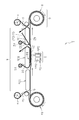
도 15는 본 발명의 제 4 실시형태에 의한 제조 장치(1)의 전체 구성을 모식적으로 나타내는 개략 측면도이다. 동 도면에 나타내는 바와 같이, 이 제조 장치(1)는 Roll to Roll 공정의 실시에 이용되는 것이고, 한쪽(동 도면 우측)의 유리롤(Ra)로부터 유리 필름 리본(G)을 인출하면서, 다른쪽(동 도면 좌측)의 유리롤(R)에 의해 권취하여 나가는 것이다. 그리고, 한쪽의 유리롤(Ra)의 하류측이고 또한 다른쪽의 유리롤(R)의 상류측에는, 유리 필름 리본(G)을 횡방향으로 반송하는 횡반송부(4)가 구비되어 있다. 이 횡반송부(4)에 주름 제거 수단(14)과 압박체(21)가 배치되어 있는 점, 및 주름 제거 수단(14)과 압박체(21)의 구성, 및 주름 제거 수단(14) 및 압박체(21)와 할단부(5)의 위치 관계 등에 대해서는 상술의 제 1 실시형태에 의한 제조 장치(1)와 동일하다. 즉, 이 제 4 실시형태에 의한 제조 장치(1)가 상술의 제 1 실시형태에 의한 그것과 상위하고 있는 점은, 한쪽의 유리롤(Ra)로부터 인출된 유리 필름(G)이 횡반송부(4)로 송출되는 점과 그것에 수반하여 한쪽의 유리롤(Ra)로부터 인출된 보호 시트(Sa)가 시트롤(ra)에 권취되는 점이다. 그 밖의 구성은 상술의 제 1 실시형태에 의한 제조 장치(1)와 동일하므로 양자에 공통의 구성 요소에 대해서는 동일 부호를 붙이고, 그 설명을 생략한다. 그리고, 이 제조 장치(1)는 한쪽의 유리롤(Ra)이 핸들부(Gx)를 갖는 유리 필름 리본(G)을 권취한 것이며, 할단부(5)에서 핸들부(Gx)를 포함하는 불요부(G1)를 제거하는 것이다. 단, 한쪽의 유리롤(Ra)이 핸들부(Gx)가 할단 제거된 유리 필름 리본을 권취한 것이어도 좋고, 그 경우에는 유리 필름 리본(G)은 할단부(5)에 의해 하나 또는 복수의 길이 방향으로 연장되는 할단 예정선을 따라서 할단된다.15 is a schematic side view that schematically shows the overall configuration of a
또한, 이상의 제 1 실시형태~제 4 실시형태에서는 주름 제거 수단(14)을 직교 막대 형상체(15)와 베이스 플레이트(16)와 평행 막대 형상체(17)와 인상체(20)로 구성했지만, 이 주름 제거 수단(14)은 직교 막대 형상체(15)만이어도 좋고, 또는 베이스 플레이트(16)만이어도 좋고, 또는 평행 막대 형상체(17)만이어도 좋고, 또한 인상체(20)만이어도 좋다. 단, 베이스 플레이트(16)만, 또는 평행 막대 형상체(17)만, 또는 인상체(20)만으로 구성하는 경우에는, 베이스 플레이트(16)의 상류측 끝면, 또는 평행 막대 형상체(17)의 상류측 끝면, 또는 인상체(20)의 상류측 끝면을 상류측을 낮게 해서 하류측으로 이행함에 따라서 점차 높아지는 경사면 또는 볼록 형상 만곡면으로 함으로써, 반송용 시트 리본(S1)의 하면과의 슬라이딩 저항을 작게 하는 것이 바람직하다.In the first to fourth embodiments described above, the wrinkle removing means 14 is constituted by the orthogonal bar-shaped
또한, 이상의 제 1 실시형태~제 4 실시형태에서는 횡반송부(4)의 정지 컨베이어(13b) 상에 주름 제거 수단(14)과 압박체(21)를 배치했지만, 정지 컨베이어(13b)를 사용하지 않고 고정 설치된 기대부의 상부에 주름 제거 수단(14)과 압박체(21)를 배치해도 좋다.Although the
또한, 이상의 제 1 실시형태~제 4 실시형태에서는 유리 필름 리본(G)과 주름 제거 수단(14) 사이에 반송용 시트 리본(S1)을 개재시켰지만, 이 반송용 시트 리본(S1)을 사용하지 않고 주름 제거 수단(14)의 상면부를 유리 필름 리본(G)이 슬라이딩하도록 해도 좋다. 단, 그 경우에는 주름 제거 수단(14)의 각 구성 요소에 의해서 유리 필름 리본(G)의 하면에 허용하기 곤란한 손상 등이 가해지지 않도록 할 필요가 있다. Although the sheet ribbon S1 for conveyance is interposed between the glass film ribbon G and the wrinkle removing means 14 in the first to fourth embodiments described above, the sheet ribbon S1 for conveyance is not used The glass film ribbon G may slide on the upper surface portion of the
또한, 이상의 제 1 실시형태~제 4 실시형태에서는 2대의 구동 컨베이어를 횡반송부(4)의 구성 요소로 했지만, 이것 대신에 1대의 구동 컨베이어를 횡반송부(4)의 구성 요소로서 해도 좋다. 단, 그 경우에는 주름 제거 수단(14) 및 압박체(21)를 그것들의 구동 컨베이어로부터 에지 컷팅 상태로 해서 정치로 설치할 필요가 있다. 또한, 3대 이상의 구동 컨베이어를 횡반송부(4)의 구성 요소로 해도 좋다.In the first to fourth embodiments described above, the two drive conveyors are constituent elements of the
도 16은 본 발명의 제 5 실시형태에 의한 제조 장치(1)의 전체 구성을 모식적으로 나타내는 개략 측면도이며, 도 17은 상기 제조 장치(1)의 횡반송부(4)의 구성을 상세하게 나타내는 확대 종단 측면도이다. 이 제 5 실시형태에 의한 제조 장치(1)가 상술의 제 1 실시형태에 의한 제조 장치(1)와 상위하고 있는 점은, 횡반송부(4)에 있어서의 정지 컨베이어(13b)의 상부에 주름 제거 수단(14) 대신에 정판(24)과 불요부 지지부(25)와 유효부 지지부(26)를 배치한 점이다. 따라서, 도 16 및 도 17에 있어서 상술의 제 1 실시형태에 의한 제조 장치(1)와 공통되는 구성 요소에 대해서는 동일 부호를 붙여서 그 설명을 생략한다. 이 경우, 상술의 제 1 실시형태에 있어서의 주름 제거 수단(14)의 구성 요소인 베이스 플레이트(16)를, 여기에서의 정판(24)으로 간주해서 주름 제거 수단(14)에 추가하여 불요부 지지부(25)와 유효부 지지부(26)를 추가한 것으로 할 수도 있다. 그리고, 이들 각 도면에 기초해서 상술의 상위점을 간략하게 설명하면, 횡반송부(4)에 있어서의 정지 컨베이어(13b)의 상부에는 유리 필름 리본(G)을 할단 위치 주변에서 안내하는 정판(24)과, 유리 필름 리본(G)을 할단한 후(직후)에 불요부(G1)와 유효부(G2)를 각각 지지하여 안내하는 불요부 지지부(15)와 유효부 지지부(16)가 정치로 설치되어 있다. 이하, 이들 구성을 상세하게 설명한다.Fig. 16 is a schematic side view schematically showing the overall configuration of the
도 18은 정판(24), 불요부 지지부(25) 및 유효부 지지부(26)의 전체적 구성을 나타내는 평면도이다. 동 도면에 나타내는 바와 같이, 정판(24)은 유리 필름 리본(G)에 대한 할단 위치(5x)를 상방에 갖도록 정치로 설치된 대략 직사각형의 판상체이다. 그리고, 정판(24)의 반송 방향 하류단에는 폭 방향 양단부에 각각 불요부 지지부(25)가 돌출됨과 아울러, 그들 불요부 지지부(25)의 폭 방향 중앙측에 유효부 지지부(26)가 돌출되어 있다. 또한, 정판(24)의 폭 방향 외측의 양단 가장자리(24a)와 불요부 지지부(25)의 각각의 폭 방향 외측의 양단 가장자리(25a)는 일직선 상에 연속되어 있다. 이 경우, 불요부 지지부(25) 및 유효부 지지부(26)는 어느 것이라도 대략 직사각 형상을 이루고, 불요부 지지부(25)가 정판(24)의 반송 방향 하류단으로부터 돌출되어 있는 치수(L1)는 불요부(G1)의 폭의 0.5~3배이다. 또한, 유효부 지지부(26)가 정판(24)의 반송 방향 하류단으로부터 돌출되어 있는 치수(L2)는 불요부 지지부(25)의 상기 치수(L1)의 1~3배이다. 또한, 동 도면으로부터 파악될 수 있는 바와 같이, 반송용 시트 리본(S1)의 폭 방향 양단은 유리 필름 리본(G)의 폭 방향 양단으로부터 돌출되어 있음과 아울러, 정지 컨베이어(13b)의 폭 방향 양단은 반송용 시트 리본(S1)의 폭 방향 양단으로부터 돌출되어 있다. 또한, 도시예에서는 반송용 시트 리본(S1)의 폭 방향 양단이 유리 필름 리본(G)의 폭 방향 양단으로부터 돌출되어 있지만, 이것과는 반대로 유리 필름 리본(G)의 폭 방향 양단이 반송용 시트 리본(S1)의 폭 방향 양단으로부터 돌출되어 있어도 좋다.18 is a plan view showing the overall configuration of the
그리고, 도 19에 나타내는 바와 같이 불요부 지지부(25) 및 유효부 지지부(26)는 모두 본 실시형태에서는 정판(24)보다 판 두께가 얇고, 또한 정판(24)의 반송 방향 하류단에 있어서의 상단부에 돌출되어 있다. 이 경우, 유효부 지지부(26)의 상면은 정판(24)의 상면과 면일 상태에서 동 방향을 향하여 연장되어 있는 것에 대하여, 불요부 지지부(25)의 상면은 정판(24)의 상면으로부터 반송 방향 하류측을 향해서 하강 경사져 있다. 이 경우의 경사 각도(θ)는 0.5~45°인 것이 바람직하고, 1~10°인 것이 보다 바람직하다. 또한, 불요부 지지부(25)의 상면은 정판(24)의 상면과 면일 상태에서 동 방향을 향해서 연장되어 있어도 좋고, 그 경우에는 유효부 지지부(26)의 상면이 정판(24)의 상면으로부터 반송 방향 하류측을 향해서 상방 경사져 있는 것이 바람직하다. 이 경우의 경사 각도도 상술의 θ와 동일하게 된다.19, both of the
도 20은 정판(24), 불요부 지지부(25) 및 유효부 지지부(26)와, 할단된 상태에 있는 유리 필름 리본(G)(G1, G2)을 나타내는 개략 평면도이며, 편의상 반송용 시트 리본 및 컨베이어의 도시를 생략하고 있다. 동 도면에 나타내는 바와 같이, 유리 필름 리본(G)은 화살표 B 방향으로 반송되면서 할단 위치(5x)에서 할단되기 때문에, 그 하류측에 있어서는 핸들부(Gx)를 포함하는 불요부(G1)의 할단 끝면(G1a)과, 유효부(G2)의 할단 끝면(G2a)이 형성되어 있다. 그리고, 유효부(G2)의 할단 끝면(G2a)과 불요부 지지부(25)의 폭 방향 안쪽단 사이에는 폭 방향 간극(27)이 각각 형성되어 있으며, 불요부 지지부(25)의 폭 방향 길이(L3)는 이들 폭 방향 간극(27)의 폭 방향 치수(L4)의 0.1~2.0배로 되고, 보다 바람직하게는 0.2~0.5배로 되고, 더욱 바람직하게는 0.25~0.3배로 된다. 또한, 유효부(G2)의 할단 끝면(G2a)은 유효부 지지부(26)의 폭 방향 양단부로부터 각각 약간 돌출되어 있을 뿐이기 때문에, 유효부 지지부(26)의 폭 방향 양단과 불요부 지지부(25)의 폭 방향 안쪽단 사이에 설치되어 있는 간극에 대해서도 마찬가지의 관계가 성립한다. 따라서, 불요부 지지부(25)의 폭 방향 길이(L3)는 그 간극에 있어서의 폭 방향 치수(L5)의 0.1~2.0배, 보다 바람직하게는 0.2~0.5배, 더욱 바람직하게는 0.25~0.3배여도 좋다. 또한, 유리 필름 리본(G)의 할단 위치(5x)로부터 정판(24)의 반송 방향 하류단까지의 치수(L6)는 유효부(G2)의 폭의 0.5~3배인 것이 바람직하다.20 is a schematic plan view showing the
동 도면으로부터 파악할 수 있는 바와 같이, 유리 필름 리본(G)이 할단된 후에, 불요부(G1)를 불요부 지지부(25)가 지지하는 형태는 불요부(G1)의 핸들부(Gx)가 불요부 지지부(25)의 폭 방향 바깥쪽단으로부터 외측으로 돌출된 상태로 되어 있다. 또한, 전체적으로 보면 불요부 지지부(25)는 불요부(G1)의 폭 방향 외측 근처의 위치를 지지하고 있다. 그리고, 도 21에 나타내는 바와 같이 불요부 지지부(25)에 의한 불요부(G1)의 반송 궤도와 유효부 지지부(26)에 의한 유효부(G2)의 반송 궤도는, 반송 방향 하류측으로 이행함에 따라서 점차 확개되고 있다. 따라서, 유리 필름 리본(G)이 할단된 후에 유효부(G2)가 유효부 지지부(26)에 의해 지지되어 이송되고, 또한 불요부(G1)가 불요부 지지부(25)에 의해 지지되어서 이송되는 동안에는, 도 22에 나타내는 바와 같이 반송용 시트 리본(S1)이 자유롭게 휜 상태에서 불요부(G1)와 유효부(G2)가 상하 방향으로 다른 위치에서 지지된다.As can be seen from the figure, in the form in which the unnecessary
이상과 같은 구성에 의하면, 도 16에 나타내는 성형부(2)로부터 방향 변환부(3)를 거쳐 횡반송부(4)에 이른 유리 필름 리본(G)은 제 1 구동 컨베이어(13a)에 의해서 횡방향으로 반송된 후, 정지 컨베이어(13b)의 상부로 갈아타서 횡방향으로 반송된다. 이 경우, 정지 컨베이어(13b)의 상부에서는 정판(24), 불요부 지지부(25) 및 유효부 지지부(26)와 슬라이딩하면서 이동하는 반송용 시트 리본(S1)에 의해서 유리 필름 리본(G) 및 그 할단 후에 있어서의 불요부(G1)와 유효부(G2)가 반송된다.16, the glass film ribbon G arriving from the forming
도 20에 나타내는 바와 같이, 정지 컨베이어(13b)의 상부에서 유리 필름 리본(G)이 정판(24) 상의 할단 위치(5x)에 이르기까지의 사이에 있어서는, 핸들부(Gx)의 폭 방향 내측 부위에 반송 방향과 직교하는 방향을 따르는 주름(Gy)이 발생되어 있다. 그런데, 불요부(G1)가 정판(24)의 반송 방향 하류단을 통과해서 불요부 지지부(25)에 의해서 지지되도록 된 경우에는, 핸들부(Gx)가 지지되지 않고 그 폭 방향 내측 부위(주름(Gy)이 발생되어 있던 부위)가 지지되게 된다. 이것에 의해, 불요부(G1)는 주름(Gy)이 소실된 상태에서 불요부 지지부(25)에 의해서 지지되어서 반송되게 된다. 또한, 중량이 큰 핸들부(Gx)가 불요부 지지부(25)의 폭 방향 바깥쪽단으로부터 돌출되어 처지려고 하기 때문에, 불요부(G1)는 유효부(G2)로부터 이반하려고 한다. 또한, 불요부 지지부(25)는 핸들부(Gx)에 발생되어 있는 물결의 영향을 받는 일 없이 불요부(G1)를 지지하고 있는 상태로 된다. 이상의 결과, 불요부(G1)가 불요부 지지부(25)에 의해 지지되어서 반송될 때에는 불요부(G1)에 발생될 수 있는 진동 등이 효과적으로 억지됨과 아울러, 불요부(G1)의 할단 끝면(G1a)과 유효부(G2)의 할단 끝면(G2a)이 빈번하게 마찰하는 사태가 회피된다. 이 경우, 불요부(G1)가 할단위치(5x)로부터 불요부 지지부(25)에 도달할 때까지의 동안에 있어서도, 핸들부(Gx)는 정판(24)의 폭 방향 양단으로부터 외측으로 돌출되어 있기 때문에 핸들부(Gx)의 자중에 의해서 그 폭 방향 내측 부위에 외측을 향하는 장력이 작용하고, 또한 그 장력에 기인해서 불요부(G1)를 유효부(G1)로부터 이반시키려고 하는 힘이 작용한다. 따라서, 유리 필름 리본(G)이 정판(24) 상에 있어도 할단 위치(5x)에서의 할단 후에 있어서는 불요부(G1)는 유효부(G2)로부터 독립된 부위로서 반송되기 때문에, 상기 장력에 의해서 주름(Gy)의 대부분이 소실됨과 아울러 불요부(G1)의 할단 끝면(G1a)과 유효부(G2)의 할단 끝면(G2a)의 간섭이 유효하게 억제된다. 또한, 유리 필름 리본(G)의 할단 위치(5x)가 불요부 지지부(25)의 반송 방향 상단으로부터 치수(L6)분에 대해 이반하고 있는 것은 다음의 이유에 의한다. 즉, 도 21에 나타내는 바와 같이 불요부 지지부(25)와 유효부 지지부(26)의 반송 궤도가 상위하고 있기 때문에, 만약 할단 위치(5x)가 불요부 지지부(25)의 반송 방향 상류단에 위치하고 있으면 할단 위치(5x)에 부당한 응력이 작용해서 적정한 할단을 행할 수 없게 되기 때문이다.20, until the glass film ribbon G reaches the
또한, 불요부 지지부(25)와 유효부(G2)(유효부 지지부(26)) 사이에는 충분한 크기의 폭 방향 간극(27)이 존재하고 있기 때문에, 불요부 지지부(25)에 의해 지지되어 있는 불요부(G1)의 폭 방향 안쪽단 주변부는, 도 22에 나타내는 바와 같이 처진 상태로 된다. 상세하게 설명하면, 불요부 지지부(25)는 불요부(G1)의 폭 방향 외측 근처 위치를 지지하고 있기 때문에 불요부(G1)의 폭 방향 내측으로의 돌출 치수가 길게 된 상태에서 불요부 지지부(25)에 의해서 지지되어 있게 되고, 이것에 기인해서 불요부(G1)의 폭 방향 안쪽단 주변부가 크게 처진 상태로 된다. 이것에 의해, 불요부(G1)의 할단 끝면(G1a)과 유효부(G2)의 할단 끝면(G2a)이 이반한 상태로 되기 때문에, 양자(G1, G2)의 할단 끝면(G1a, G2a)끼리가 마찰하는 사태가 보다 한층 확실하게 회피된다. 이러한 이점은, 도 21에 나타내는 바와 같이 불요부 지지부(25)와 유효부 지지부(26)의 반송 궤도가 상위하고 있는 것에 유래해서 한층 현저해진다. 또한, 도 22로부터 추인할 수 있는 바와 같이, 만약 불요부 지지부(25)와 유효부 지지부(26)의 반송 궤도가 동일했다고 해도 불요부 지지부(25)에 의해 지지되어 있는 불요부(G1)는 그 폭 방향 안쪽단 주변부가 크게 처진 상태로 되었기 때문에, 불요부(G1)의 할단 끝면(G1a)과 유효부(G2)의 할단 끝면(G2a)이 마찰되는 사태를 회피할 수 있다. 그리고, 이렇게 한 경우에는 유리 필름 리본(G)의 할단 위치(5x)를 불요부 지지부(25)의 반송 방향 상류단 또한 그 근방에 위치시킬 수 있다.Since the
이상과 같이 하여 불요부 지지부(25)에 의해서 지지되어서 반송된 불요부(G1)는 폐기 처리부(도시하지 않음)로 이송되어 세분화된다. 한편, 유효부 지지부(26)에 의해서 지지되어서 반송된 유효부(G2)는 권취부(6)에 이름으로써, 최종적으로 이미 설명된 도 10에 나타낸 상태와 마찬가지로 권심(18)의 둘레에 유리 필름 리본(G)(유효부(G2))과 보호 시트(S)가 겹쳐진 상태에서 권취되어서 이루어지는 유리롤(R)로 된다. 이렇게 해서 얻어진 유리롤(R)은 할단 끝면의 손상 등이 매우 적은 고품질의 것으로 된다.The unneeded portion G1 supported and supported by the unnecessary
도 23 및 도 24는 본 발명의 제 6 실시형태에 의한 제조 장치(1)의 요부 구성을 예시하고 있다. 동 도면에 나타내는 바와 같이, 이 제 6 실시형태에 의한 제조 장치(1)가 상술의 제 5 실시형태에 의한 제조 장치(1)와 상위하고 있는 점은, 정지 컨베이어(13b)의 상부에 있어서 정판(24), 불요부 지지부(25) 및 유효부 지지부(26)와, 유리 필름 리본(G)(불요부(G1) 및 유효부(G2)를 포함함) 사이에 반송용 시트 리본을 개재시키고 있지 않은 점에 있다. 이러한 구성이어도, 유리 필름 리본(G)에 작용하는 상류측으로부터의 이송력 및 하류측으로부터의 인장력에 의해서 유리 필름 리본(G)은 정판(24), 불요부 지지부(25) 및 유효부 지지부(26)의 상면과 슬라이딩하면서 반송된다. 이 경우, 정판(24)의 상류측 끝면(24a)은 유리 필름 리본(G)의 하면에 슬라이딩에 의한 손상 등이 생기지 않도록 만곡해서 매끄럽게 상면(24b)으로 이어져 있다. 이러한 구성에 의해서도 상술의 제 5 실시형태에 있어서의 경우와 마찬가지의 동작이 행해지고, 또한 마찬가지의 작용 효과가 얻어진다. 또한, 도 23 및 도 24에 있어서 상술의 제 5 실시형태에 의한 제조 장치(1)와 공통의 구성 요소에 대해서는 동일 부호를 붙이고, 그 설명을 생략한다.Figs. 23 and 24 illustrate the essential structure of the
도 25는 본 발명의 제 7 실시형태에 의한 제조 장치(1)의 요부 구성을 예시하고 있다. 동 도면에 나타내는 바와 같이, 이 제 7 실시형태에 의한 제조 장치(1)가 상술의 제 6 실시형태에 의한 제조 장치(1)와 상위하고 있는 점은, 불요부 지지부(25)가 폭 방향 외측으로부터 폭 방향 내측을 향해서 하강 경사져 있는 점에 있다. 또한, 이 제 7 실시형태에 있어서는 상술의 제 5 실시형태와 마찬가지로, 정판, 불요부 지지부(25) 및 유효부 지지부(26)와, 유리 필름 리본(G)(불요부(G1) 및 유효부(G2)를 포함함) 사이에 반송용 시트 리본을 개재시켜도 좋다. 그리고, 이 제 7 실시형태에 있어서의 구성에 의해서도 상술의 제 6 실시형태에 있어서의 경우와 마찬가지의 동작이 행해지고, 또한 마찬가지의 작용 효과가 얻어진다. 또한, 도 25에 있어서 상술의 제 6 실시형태에 의한 제조 장치(1)와 공통의 구성 요소에 대해서는 동일 부호를 붙이고, 그 설명을 생략한다.Fig. 25 illustrates a configuration of the essential part of the
도 26은 본 발명의 제 8 실시형태에 의한 제조 장치(1)의 요부 구성을 예시하고 있다. 동 도면에 나타내는 바와 같이, 이 제 8 실시형태에 의한 제조 장치(1)가 상술의 제 6 실시형태에 의한 제조 장치(1)와 상위하고 있는 점은, 불요부 지지부(25)가 폭 방향 내측으로부터 폭 방향 외측을 향해서 하강 경사져 있는 점에 있다. 또한, 이 제 8 실시형태에 있어서도 상술의 제 5 실시형태와 마찬가지로 정판, 불요부 지지부(25) 및 유효부 지지부(26)와, 유리 필름 리본(G)(불요부(G1) 및 유효부(G2)를 포함함) 사이에 반송용 시트 리본을 개재시켜도 좋다. 그리고, 이 제 8 실시형태에 있어서의 구성에 의해서도 상술의 제 6 실시형태에 있어서의 경우와 마찬가지의 동작이 행해지고, 또한 마찬가지의 작용 효과가 얻어진다. 또한, 도 26에 있어서 상술의 제 6 실시형태에 의한 제조 장치(1)와 공통의 구성 요소에 대해서는 동일 부호를 붙이고, 그 설명을 생략한다.Fig. 26 illustrates the essential structure of the
도 27은 본 발명의 제 9 실시형태에 의한 제조 장치(1)의 전체 구성을 모식적으로 나타내는 개략 측면도이다. 동 도면에 나타내는 바와 같이, 이 제조 장치(1)는 Roll to Roll 공정의 실시에 이용되는 것이고, 한쪽(동 도면 우측)의 유리롤(Ra)로부터 유리 필름 리본(G)을 인출하면서, 다른쪽(동 도면 좌측)의 유리롤(R)에 의해 권취해 가는 것이다. 그 때에는 한쪽의 유리롤(Ra)로부터 유리 필름 리본(G)을 인출하는 것에 수반하여 한쪽의 유리롤(Ra)로부터 인출된 보호 시트(Sa)가 시트롤(ra)에 권취되도록 되어 있다. 여기서, 한쪽의 유리롤(Ra)이 핸들부가 이미 할단 제거되어 있는 유리 필름 리본(G)을 권취한 것인 경우에는, 불요부(G1)는 유리 필름 리본(G)의 폭 방향 양단부에 각각 존재하고 있거나, 또는 폭 방향 일단부에만 존재하고 있거나 하다. 그리고, 유리 필름 리본(G)의 폭 방향 치수를 리사이징하기 위해서 불요부(G1)의 할단 제거가 행해지는 경우가 있다. 이러한 경우에, 횡반송부(4)에 있어서는 정판(24)의 반송 방향 하류단에 있어서의 폭 방향 양단부 또는 폭 방향 일단부에 불요부 지지부(25)가 돌출되고, 또한 정판(24)의 반송 방향 하류단에 있어서의 불요부 지지부(25)의 폭 방향 중앙측에 유효부 지지부(26)가 돌출된다. 따라서, 유리 필름 리본(G)의 폭 방향 양단부에 각각 불요부(G1)가 존재하고 있는 경우에는, 도 28a에 나타내는 바와 같이 할단 후에 있어서의 한 쌍의 불요부(G1)가 한 쌍의 불요부 지지부(25)에 의해서 지지된다. 또한, 유리 필름 리본(G)의 폭 방향 일 단부에만 불요부(G1)가 존재하고 있는 경우에는, 도 28b에 나타내는 바와 같이 할단 후에 있어서의 하나의 불요부(G1)가 단일의 불요부 지지부(25)에 의해서 지지된다. 이상의 사항 이외의 구성은 상술의 제 6 실시형태에 의한 제조 장치(1)와 동일하므로 양자에 공통의 구성 요소에 대해서는 동일 부호를 붙이고, 그 설명을 생략한다.Fig. 27 is a schematic side view schematically showing an overall configuration of a
또한, 상술의 제 5~제 9 실시형태에 의한 제조 장치(1)는 방향 변환부(3)로부터 횡반송부(4)에 이르는 유리 필름 리본(G)의 진행 경로가 횡반송부(4)에서의 유리 필름 리본(G)의 진행 경로보다 하방으로 처져 있지 않았지만, 이미 설명한 도 14에 나타내는 형태와 마찬가지로 성형부(2)로부터 종방향 하방으로 인출된 유리 필름 리본(G)이 방향 변환부(3)에 있어서 횡반송부(4)에서의 진행 경로보다 하방으로 처진 후에 상방으로 이행하여 횡반송부(4)에 이르는 진행 경로로 되도록 구성해도 좋다.In the
그리고, 상술의 제 5 실시형태~제 9 실시형태에서는 횡반송부(4)의 정지 컨베이어(13b) 상에 정판(24), 불요부 지지부(25) 및 유효부 지지부(26)를 배치했지만, 정지 컨베이어(13b)를 사용하지 않고 고정 설치된 기대부의 상부에 정판(24), 불요부 지지부(25) 및 유효부 지지부(26)를 배치해도 좋다.Although the
또한, 상술의 제 5 실시형태~제 9 실시형태에서는 2대의 구동 컨베이어를 횡반송부(4)의 구성 요소로 했지만, 이것 대신에 1대의 구동 컨베이어를 횡반송부(4)의 구성 요소로 해도 좋다. 단, 그 경우에는 정판(24), 불요부 지지부(25) 및 유효부 지지부(26)를 그것들의 구동 컨베이어로부터 에지 컷팅 상태로 해서 정치로 설치할 필요가 있다. 또한, 3대 이상의 구동 컨베이어를 횡반송부(4)의 구성 요소로 해도 좋다.In the fifth to ninth embodiments described above, the two drive conveyors are constituent elements of the
또한, 상술의 제 5 실시형태~제 9 실시형태에서는 정판(24)의 반송 방향 하류단에 불요부 지지부(25)와 유효부 지지부(26)를 돌출시켰지만, 유리 필름 리본(G)의 유효부(G2)가 하류측의 제 2 구동 컨베이어(13c) 상으로 원활하게 갈아타서 반송되도록 정판(24)과 제 2 구동 컨베이어(13c)를 가까이 하여 배치한 경우에는 유효부 지지부(26)를 설치하지 않아도 좋다.Although the unnecessary
또한, 이상의 제 1 실시형태~제 6 실시형태에서는 횡반송부(4)에 배열되는 각 컨베이어(13a, 13b, 13c)를 벨트 컨베이어로 구성했지만, 이것 대신에 또는 이것과 함께 각 컨베이어의 일부 또는 전부를 복수(다수)의 롤러가 자전하는 구성으로 한 롤러 컨베이어나 부상 반송 수단 등을 적절히 조합시켜서 구성하도록 해도 좋다. 또한, 불요부 지지부(25)에 대해서도 판상체로 하지 않고, 그러한 롤러 컨베이어 등으로 구성하도록 해도 좋다.In the first to sixth embodiments described above, the
또한, 이상의 적절한 실시형태에서는 유리 필름 리본(G)을 성형하기 위해서 오버플로우 다운드로우법을 채용했지만, 이것 대신에 슬롯 다운드로우법 등의 다른 다운드로우법이나 리드로우법 등을 채용하는 것도 가능하다. 또한, 유리 필름 리본(G)을 성형하는 방법으로서는 플로트 배스로부터 유리 필름 리본을 인출해서 횡반송부에 의해 반송하도록 한 플로트법을 채용하는 것이 가능하다.In the above preferred embodiments, the overflow down-draw method is employed to form the glass film ribbon G. However, other down-draw methods such as the slot down-draw method and the lead-down method may be employed . As a method for molding the glass film ribbon G, it is possible to employ a float method in which a glass film ribbon is taken out from a float bath and conveyed by a transverse conveying portion.
또한, 이상의 모든 실시형태는 할단부(5)에 의해 핸들부를 할단해서 제거한 유리 필름 리본(G2)을 롤 형상으로 권취해서 유리롤(R)을 제작하는 권취부(6)를 갖는 구성으로 했지만, 이러한 권취부(6)를 갖지 않고 할단부(5)에 의해 불요부(G1)를 할단하여 제거한 유리 필름 리본(유효부(G2))을 길이 방향 소정 길이씩 직사각형으로 절단해서 복수의 직사각형의 각 유리 필름의 상호간에 보호 시트를 개재시켜서 이루어지는 유리 필름 적층체를 제작하는 구성으로 해도 좋다.In all of the above-described embodiments, the winding
1: 유리 필름 리본 제조 장치 2: 성형부
3: 방향 변환부 4: 횡반송부
5: 할단부 5x: 할단 위치
6: 권취부 13a: 제 1 구동 컨베이어
13b: 정지 컨베이어 13c: 제 2 구동 컨베이어
14: 주름 제거 수단 15: 직교 막대 형상체
16: 베이스 플레이트 17: 평행 막대 형상체
20: 인상체 21: 압박체
24: 정판 25: 불요부 지지부
26: 유효부 지지부 G: 유리 필름 리본
G1: 불요부 G2: 유효부
Gx: 핸들부 R: 유리롤
S1: 반송용 시트 리본 1: Glass film ribbon producing apparatus 2: Molding section
3: direction changing section 4: transverse conveying section
5:
6: winding
13b: stop
14: wrinkle removing means 15: orthogonal bar-shaped body
16: base plate 17: parallel rod-shaped body
20: impression body 21: pressing body
24: top plate 25:
26: effective part support G: glass film ribbon
G1: unnecessary part G2: valid part
Gx: Handle part R: Glass roll
S1: sheet ribbon for conveying
Claims (23)
상기 할단부에 의해 상기 유리 필름 리본에 대한 할단이 행해지기 이전에, 상기 횡반송부에 설치된 주름 제거 수단에 의해서 상기 유리 필름 리본에 발생된 주름을 제거하는 것을 특징으로 하는 유리 필름 리본 제조 방법.The glass film ribbon is conveyed in the transverse direction by the transverse conveying section while the glass film ribbon is conveyed in the conveying path of the transverse conveying section by the glass film ribbon In the method,
Wherein the wrinkle generated on the glass film ribbon is removed by the wrinkle removing means provided on the transverse conveying section before the end of the glass film ribbon is performed by the end portion.
상기 주름 제거 수단은 상기 횡반송부에 의해 반송되는 유리 필름 리본의 하면측에 설치되어 있는 것을 특징으로 하는 유리 필름 리본 제조 방법.The method according to claim 1,
Wherein the wrinkle removing means is provided on a lower surface side of the glass film ribbon conveyed by the transverse conveying portion.
상기 주름 제거 수단은 상기 할단부에 의한 상기 유리 필름 리본에 대한 할단 위치보다 상류측에 배치되어서 상기 유리 필름 리본의 반송 방향과 직교하는 방향으로 연장되는 직교 막대 형상체가 상기 유리 필름 리본을 하면측으로부터 들어올림으로써 상기 주름을 제거하는 것을 특징으로 하는 유리 필름 리본 제조 방법.3. The method according to claim 1 or 2,
Wherein the wrinkle removing means is disposed on an upstream side of a cut end position of the glass film ribbon by the cutter so that an orthogonal bar shaped body extending in a direction orthogonal to the conveying direction of the glass film ribbon presses the glass film ribbon And removing the wrinkles by lifting the wrinkles.
상기 주름 제거 수단은 상기 할단부에 의한 상기 유리 필름 리본에 대한 할단 위치의 상류측으로부터 하류측에 걸쳐서 배치되어서 상기 유리 필름 리본의 반송 방향과 평행한 방향으로 연장되는 평행 막대 형상체가 상기 유리 필름 리본의 폭 방향 양단부를 하면측으로부터 각각 들어올림으로써 상기 주름을 제거하는 것을 특징으로 하는 유리 필름 리본 제조 방법.4. The method according to any one of claims 1 to 3,
Wherein the wrinkle removing means comprises a parallel rod-shaped body extending from an upstream side to a downstream side of a cut end position of the glass film ribbon by the cutter and extending in a direction parallel to a conveying direction of the glass film ribbon, And the wrinkles are removed by lifting both end portions in the width direction of the glass ribbon from the lower side.
상기 주름 제거 수단은 상기 할단부에 의한 상기 유리 필름 리본에 대한 할단 위치의 상류측으로부터 하류측에 걸쳐서 배치되어서 상기 유리 필름 리본을 하면측으로부터 지지하는 베이스 플레이트를 갖고, 상기 유리 필름 리본의 폭 방향 양단부를 상기 베이스 플레이트의 폭 방향 양단으로부터 돌출시켜서 띄우는 것을 특징으로 하는 유리 필름 리본 제조 방법.5. The method according to any one of claims 1 to 4,
Wherein the wrinkle removing means has a base plate which is disposed from the upstream side to the downstream side of the cut end position of the glass film ribbon by the cutter and supports the glass film ribbon from the bottom side, Wherein both ends of the base plate are protruded from both ends in the width direction of the base plate.
상기 베이스 플레이트의 상면은 폭 방향 중앙부보다 폭 방향 양단부가 낮게 되도록 형성되어 있는 것을 특징으로 하는 유리 필름 리본 제조 방법.6. The method of claim 5,
Wherein the upper surface of the base plate is formed so that both end portions in the width direction are lower than a widthwise center portion thereof.
상기 주름 제거 수단은 상기 할단부에 의한 상기 유리 필름 리본에 대한 할단 위치를 포함하고 또한 상기 할단 위치로부터 상류측과 하류측을 향하는 영역에 배치된 인상체가 상기 유리 필름 리본을 하면측으로부터 각각 들어올림으로써 상기 주름을 제거하는 것을 특징으로 하는 유리 필름 리본 제조 방법.7. The method according to any one of claims 1 to 6,
Wherein the wrinkle removing means includes a detaching position for the glass film ribbon by the detaching unit and the impression body arranged in the region facing the upstream side and the downstream side from the detaching position lifts the glass film ribbon from the bottom side Thereby removing the wrinkles.
상기 횡반송부에는 상기 유리 필름 리본의 폭 방향 양단부에 대응하는 위치에 각각 압박체가 더 설치되고, 이 압박체는 상기 주름 제거 수단이 상기 유리 필름 리본의 폭 방향 양단부를 띄운 상태로 지지하고 있을 때에, 상기 폭 방향 양단부를 각각 상방으로부터 누르는 것을 특징으로 하는 유리 필름 리본 제조 방법.8. The method according to any one of claims 1 to 7,
Wherein the transverse conveying unit is further provided with a pressing body at positions corresponding to both end portions in the width direction of the glass film ribbon and the pressing body is configured such that when the wrinkle removing means supports both ends of the glass film ribbon in the width direction, , And the opposite ends in the width direction are pressed from above, respectively.
상기 주름 제거 수단은 정치로 설치되어 있는 것을 특징으로 하는 유리 필름 리본 제조 방법.9. The method according to any one of claims 1 to 8,
Wherein the wrinkle removing means is provided in a stationary state.
상기 주름 제거 수단과 상기 유리 필름 리본 사이에 가요성을 갖는 반송용 시트 리본이 개재되고, 상기 반송용 시트 리본의 하면이 상기 주름 제거 수단과 슬라이딩하면서 이동함으로써 상기 반송용 시트 리본이 상기 유리 필름 리본을 반송하는 것을 특징으로 하는 유리 필름 리본 제조 방법.10. The method of claim 9,
And a conveying sheet ribbon having flexibility is interposed between the wrinkle removing means and the glass film ribbon, and the lower surface of the conveying sheet ribbon is moved while sliding on the wrinkle removing means, To the glass ribbon (3).
상기 횡반송부의 상류측에 성형부로부터 종방향 하방으로 인출된 유리 필름 리본을 횡방향으로의 반송으로 방향을 변환시키는 방향 변환부를 구비하고 있는 것을 특징으로 하는 유리 필름 리본 제조 방법.11. The method according to any one of claims 1 to 10,
And a direction changing section for changing the direction of the glass film ribbon drawn in the longitudinal direction downward from the forming section on the upstream side of the transverse conveying section by conveying the glass film ribbon in the transverse direction.
상기 횡반송부의 하류측에 상기 유리 필름 리본을 보호 시트에 겹쳐서 권취하는 롤 권취부를 구비하고 있는 것을 특징으로 하는 유리 필름 리본 제조 방법.12. The method according to any one of claims 1 to 11,
And a roll winding portion for winding the glass film ribbon on the protective sheet in a rolled state on the downstream side of the transverse conveying portion.
상기 횡반송부에 상기 유리 필름 리본에 발생된 주름을 상기 할단부에 의해 상기 유리 필름 리본에 대한 할단이 행해지기 이전에 제거하는 주름 제거 수단을 설치한 것을 특징으로 하는 유리 필름 리본 제조 장치.A glass film ribbon manufacturing apparatus provided with a transverse conveying section for conveying the glass film ribbon in the transverse direction and a separating section provided on the conveying path of the transverse conveying section and for separating the glass film ribbon along the predetermined dividing line extending in the longitudinal direction In this case,
And a wrinkle removing means for removing wrinkles generated in the glass film ribbon before the cutting of the glass film ribbon is performed by the cutter portion in the transverse conveying portion.
상기 횡반송부에는 상기 주름 제거 수단이 상기 유리 필름 리본의 폭 방향 양단부를 띄운 상태로 지지하고 있을 때에, 상기 폭 방향 양단부를 각각 상방으로부터 누르는 압박체가 더 설치되어 있는 것을 특징으로 하는 유리 필름 리본 제조 장치.14. The method of claim 13,
Wherein the wrinkle removing means is further provided with a pressing body which presses the both end portions in the width direction from above when the wrinkle removing means supports both end portions in the width direction of the glass film ribbon in a floating state in the transverse carrying section Device.
상기 할단부에 의해 상기 유리 필름 리본이 할단된 후에, 상기 불요부는 상기 유효부와의 사이에 폭 방향 간극을 갖는 불요부 지지부에 의해서 지지되는 것을 특징으로 하는 유리 필름 리본 제조 방법.The glass film ribbon is conveyed in the transverse direction by the transverse conveying section while the glass film ribbon is conveyed by the unloading section disposed on the conveying path of the transverse conveying section, A method for manufacturing a glass film ribbon, comprising the steps of:
Wherein the unused portion is supported by a unneeded portion having a widthwise gap between the unused portion and the effective portion after the glass film ribbon is removed by the uncut portion.
상기 불요부는 상기 유효부보다 후육의 핸들부를 갖고, 상기 불요부 지지부는 상기 핸들부가 폭 방향 외측으로 돌출된 상태에서 상기 불요부를 지지하는 것을 특징으로 하는 유리 필름 리본 제조 방법.16. The method of claim 15,
Wherein the unnecessary portion has a handle portion of the lower portion than the effective portion, and the unnecessary portion supporting portion supports the unnecessary portion in a state where the handle portion protrudes outward in the width direction.
상기 불요부 지지부는 상기 불요부의 폭 방향 외측 근처 위치를 지지하는 것을 특징으로 하는 유리 필름 리본 제조 방법.17. The method according to claim 15 or 16,
Wherein the unnecessary portion supporting portion supports a position near the width direction outer side of the unnecessary portion.
상기 불요부 지지부의 폭 방향 길이는 상기 폭 방향 간극의 폭 방향 길이의 0.1~2.0배인 것을 특징으로 하는 유리 필름 리본 제조 방법.18. The method according to any one of claims 15 to 17,
Wherein the width direction length of the unnecessary portion supporting portion is 0.1 to 2.0 times the width direction length of the width direction gap.
상기 유효부는 폭 방향 양단부가 각각 폭 방향 외측으로 돌출된 상태에서 유효부 지지부에 의해서 지지되어 있는 것을 특징으로 하는 유리 필름 리본 제조 방법.19. The method according to any one of claims 15 to 18,
Wherein the effective portion is supported by an effective portion supporting portion in a state where both end portions in the width direction protrude outward in the width direction.
상기 불요부 지지부에 의한 상기 불요부의 반송 궤도와 상기 유효부 지지부에 의한 상기 유효부의 반송 궤도는 반송 방향 하류측으로 이행함에 따라서 상하 방향으로 점차 확개되고 있는 것을 특징으로 하는 유리 필름 리본 제조 방법.20. The method of claim 19,
Wherein the conveying path of the unnecessary portion by the unnecessary portion supporting portion and the conveying path of the effective portion by the effective portion supporting portion are gradually expanded in the vertical direction as they move to the downstream side in the conveying direction.
상기 불요부 지지부와 상기 유효부 지지부는 상기 횡반송부의 반송 경로를 따라서 정치로 설치된 정판의 반송 방향 하류단에 돌출되어 있는 것을 특징으로 하는 유리 필름 리본 제조 방법.21. The method according to claim 19 or 20,
Wherein the unnecessary portion supporting portion and the effective portion supporting portion protrude from the downstream end in the conveying direction of the top plate provided at a fixed position along the conveying path of the transverse conveying portion.
상기 정판, 상기 불요부 지지부 및 상기 유효부 지지부와, 상기 유리 필름 리본 사이에 가요성을 갖는 반송용 시트 리본을 개재시키고, 상기 반송용 시트 리본의 하면이 상기 정판, 상기 불요부 지지부 및 상기 유효부 지지부와 슬라이딩하면서 이동함으로써 상기 반송용 시트 리본이 상기 유리 필름 리본을 반송하는 것을 특징으로 하는 유리 필름 리본 제조 방법.22. The method of claim 21,
And a conveying sheet ribbon having flexibility between the top plate, the unnecessary portion supporting portion and the effective portion supporting portion and between the glass film ribbons is interposed between the top plate, the unnecessary portion supporting portion, And the transporting sheet ribbon transports the glass film ribbon by sliding while sliding on the sub-support portion.
상기 할단부에 의해 상기 유리 필름 리본이 할단된 후에, 상기 불요부는 상기 유효부와의 사이에 폭 방향 간극을 갖는 불요부 지지부에 의해서 지지되도록 구성된 것을 특징으로 하는 유리 필름 리본 제조 장치.The glass film ribbon is conveyed in the transverse direction by the transverse conveying section while the glass film ribbon is conveyed by the unloading section disposed on the conveying path of the transverse conveying section, A glass ribbon manufacturing apparatus configured to cut along a scheduled breaking line forming a boundary line of an effective portion,
Wherein the unnecessary portion is configured to be supported by the unnecessary portion supporting portion having a widthwise gap with the effective portion after the glass film ribbon is removed by the detaching portion.
Applications Claiming Priority (5)
| Application Number | Priority Date | Filing Date | Title |
|---|---|---|---|
| JP2013176819A JP6136070B2 (en) | 2013-08-28 | 2013-08-28 | Glass film ribbon manufacturing method and glass film ribbon manufacturing apparatus |
| JP2013176817 | 2013-08-28 | ||
| JPJP-P-2013-176817 | 2013-08-28 | ||
| JPJP-P-2013-176819 | 2013-08-28 | ||
| PCT/JP2014/071972 WO2015029888A1 (en) | 2013-08-28 | 2014-08-22 | Glass film ribbon manufacturing method and glass film ribbon manufacturing device |
Related Child Applications (1)
| Application Number | Title | Priority Date | Filing Date |
|---|---|---|---|
| KR1020207024196A Division KR102221540B1 (en) | 2013-08-28 | 2014-08-22 | Glass film ribbon manufacturing method and glass film ribbon manufacturing device |
Publications (2)
| Publication Number | Publication Date |
|---|---|
| KR20160048718A true KR20160048718A (en) | 2016-05-04 |
| KR102184301B1 KR102184301B1 (en) | 2020-11-30 |
Family
ID=52586447
Family Applications (1)
| Application Number | Title | Priority Date | Filing Date |
|---|---|---|---|
| KR1020157033111A KR102184301B1 (en) | 2013-08-28 | 2014-08-22 | Glass film ribbon manufacturing method and glass film ribbon manufacturing device |
Country Status (6)
| Country | Link |
|---|---|
| US (2) | US9932259B2 (en) |
| EP (2) | EP3326978B1 (en) |
| KR (1) | KR102184301B1 (en) |
| CN (2) | CN105307992B (en) |
| TW (2) | TWI625312B (en) |
| WO (1) | WO2015029888A1 (en) |
Cited By (1)
| Publication number | Priority date | Publication date | Assignee | Title |
|---|---|---|---|---|
| KR20190127656A (en) * | 2017-03-13 | 2019-11-13 | 니폰 덴키 가라스 가부시키가이샤 | Manufacturing Method Of Glass Film |
Families Citing this family (20)
| Publication number | Priority date | Publication date | Assignee | Title |
|---|---|---|---|---|
| WO2017095859A1 (en) * | 2015-12-01 | 2017-06-08 | Corning Incorporated | Glass web separating devices and methods |
| JP6876725B2 (en) * | 2016-06-03 | 2021-05-26 | コーニング インコーポレイテッド | Devices and methods for managing mechanically induced stresses at the crack tips when separating flexible glass ribbons |
| JP6796282B2 (en) * | 2016-10-11 | 2020-12-09 | 日本電気硝子株式会社 | Glass film manufacturing method |
| JP7238405B2 (en) * | 2016-12-06 | 2023-03-14 | 日本電気硝子株式会社 | Quality inspection method for strip glass film |
| JP6720900B2 (en) * | 2017-03-14 | 2020-07-08 | 日本電気硝子株式会社 | Glass roll manufacturing method |
| JP6909403B2 (en) * | 2017-07-31 | 2021-07-28 | 日本電気硝子株式会社 | Glass film manufacturing method |
| JP6839419B2 (en) * | 2017-07-31 | 2021-03-10 | 日本電気硝子株式会社 | Glass film manufacturing method |
| KR102583667B1 (en) | 2017-10-30 | 2023-10-04 | 코닝 인코포레이티드 | Systems and methods for processing thin glass ribbons |
| US20200290916A1 (en) * | 2017-10-31 | 2020-09-17 | Corning Incorporated | Systems and methods for processing thin glass ribbons |
| JP6883282B2 (en) * | 2017-11-27 | 2021-06-09 | 日本電気硝子株式会社 | Glass roll manufacturing method |
| JP7054170B2 (en) * | 2017-11-30 | 2022-04-13 | 三星ダイヤモンド工業株式会社 | Belt conveyor equipment |
| JP7324424B2 (en) * | 2018-01-31 | 2023-08-10 | 日本電気硝子株式会社 | GLASS ROLL, GLASS ROLL MANUFACTURING METHOD AND QUALITY EVALUATION METHOD |
| JP7148837B2 (en) * | 2018-06-22 | 2022-10-06 | 日本電気硝子株式会社 | Glass roll manufacturing method |
| JP2022547575A (en) * | 2019-09-12 | 2022-11-14 | コーニング インコーポレイテッド | Method and apparatus for manufacturing glass ribbon |
| DE102019129036A1 (en) * | 2019-10-28 | 2021-04-29 | Schott Ag | Process for the production of glass panes and glass panes produced in accordance with the process and their use |
| WO2021131617A1 (en) * | 2019-12-23 | 2021-07-01 | 日本電気硝子株式会社 | Method for manufacturing glass film and device for manufacturing same |
| US20230026145A1 (en) * | 2019-12-24 | 2023-01-26 | Nippon Electric Glass Co., Ltd. | Glass film production method, glass roll production method, and glass film production device |
| JP2022093901A (en) * | 2020-12-14 | 2022-06-24 | 日本電気硝子株式会社 | Method and apparatus for manufacturing glass plate |
| JP2022108103A (en) * | 2021-01-12 | 2022-07-25 | 日本電気硝子株式会社 | Method for manufacturing glass film |
| WO2023177539A1 (en) * | 2022-03-15 | 2023-09-21 | Corning Incorporated | Methods and apparatus for manufacturing a ribbon |
Citations (5)
| Publication number | Priority date | Publication date | Assignee | Title |
|---|---|---|---|---|
| JP2011144092A (en) * | 2010-01-18 | 2011-07-28 | Nippon Electric Glass Co Ltd | Method for cutting plate-like glass and apparatus for cutting the same |
| JP2012106898A (en) * | 2010-11-19 | 2012-06-07 | Nippon Electric Glass Co Ltd | Method for producing glass film |
| JP2012111649A (en) | 2010-11-22 | 2012-06-14 | Nippon Electric Glass Co Ltd | Device for cleaving strip-shaped glass film and method for cleaning strip-shaped glass film |
| JP2012211074A (en) | 2011-03-30 | 2012-11-01 | Corning Inc | Method of fabricating glass ribbon |
| WO2012169002A1 (en) * | 2011-06-07 | 2012-12-13 | 日本電気硝子株式会社 | Method for cutting plate-like glass, and cutting device therefor |
Family Cites Families (21)
| Publication number | Priority date | Publication date | Assignee | Title |
|---|---|---|---|---|
| GB1246481A (en) * | 1968-03-29 | 1971-09-15 | Pilkington Brothers Ltd | Improvements in or relating to the cutting of glass |
| SE403280B (en) * | 1972-10-12 | 1978-08-07 | Glaverbel | KIT AND DEVICE TO CUT GLASS OR GLASS CRYSTALLINIC MATERIAL ALONG A DETERMINED LINE |
| JPS5910099Y2 (en) * | 1979-10-22 | 1984-03-30 | セントラル硝子株式会社 | Glass plate breaking separation device |
| JPS5665931A (en) | 1979-10-31 | 1981-06-04 | Kobe Steel Ltd | Manufacture of cold-rolled steel sheet for press formation |
| JPS6076318A (en) | 1983-10-04 | 1985-04-30 | Toray Ind Inc | Smoothing device of film |
| JPH08175726A (en) | 1994-12-22 | 1996-07-09 | Toray Ind Inc | Unwrinkling roll for sheet material |
| JP5522516B2 (en) | 2009-12-07 | 2014-06-18 | 日本電気硝子株式会社 | Sheet glass cutting method and apparatus |
| JP5418977B2 (en) * | 2009-12-08 | 2014-02-19 | 日本電気硝子株式会社 | Glass film cutting method and apparatus |
| US9656901B2 (en) * | 2010-03-03 | 2017-05-23 | Nippon Electric Glass Co., Ltd. | Method of manufacturing a glass roll |
| JP5669001B2 (en) * | 2010-07-22 | 2015-02-12 | 日本電気硝子株式会社 | Glass film cleaving method, glass roll manufacturing method, and glass film cleaving apparatus |
| JP5645063B2 (en) * | 2010-07-23 | 2014-12-24 | 日本電気硝子株式会社 | Glass film manufacturing apparatus and manufacturing method |
| JP5696393B2 (en) * | 2010-08-02 | 2015-04-08 | 日本電気硝子株式会社 | Cleaving method of glass film |
| JP2012096936A (en) | 2010-10-29 | 2012-05-24 | Asahi Glass Co Ltd | Apparatus and method for cutting edge of glass ribbon, and apparatus and method for manufacturing glass product |
| KR101800223B1 (en) * | 2011-06-08 | 2017-11-22 | 니폰 덴키 가라스 가부시키가이샤 | Method for cutting plate-like glass, and cutting device therefor |
| TWI586612B (en) * | 2011-11-18 | 2017-06-11 | 康寧公司 | Apparatus and method for trimming a moving glass ribbon |
| TW201412658A (en) * | 2012-09-26 | 2014-04-01 | Corning Inc | Edge trim management for flexible glass ribbon |
| US9216924B2 (en) * | 2012-11-09 | 2015-12-22 | Corning Incorporated | Methods of processing a glass ribbon |
| US9643878B2 (en) * | 2012-11-13 | 2017-05-09 | Nippon Electric Glass Co., Ltd. | Sheet glass manufacturing method and manufacturing device |
| EP2925684B1 (en) * | 2012-11-29 | 2017-09-06 | Corning Incorporated | Method and apparatus for fabricating glass ribbon of various widths |
| US9919381B2 (en) * | 2013-01-30 | 2018-03-20 | Corning Incorporated | Apparatus and methods for continuous laser cutting of flexible glass |
| EP2991939B1 (en) * | 2013-05-03 | 2017-04-12 | Corning Incorporated | Method and apparatus for conveying a glass ribbon |
-
2014
- 2014-08-22 KR KR1020157033111A patent/KR102184301B1/en active IP Right Grant
- 2014-08-22 EP EP17199114.4A patent/EP3326978B1/en active Active
- 2014-08-22 CN CN201480031453.9A patent/CN105307992B/en active Active
- 2014-08-22 WO PCT/JP2014/071972 patent/WO2015029888A1/en active Application Filing
- 2014-08-22 EP EP14839514.8A patent/EP3040317B1/en active Active
- 2014-08-22 US US14/908,718 patent/US9932259B2/en active Active
- 2014-08-22 CN CN201710767435.2A patent/CN107382048B/en active Active
- 2014-08-27 TW TW103129440A patent/TWI625312B/en active
- 2014-08-27 TW TW107108888A patent/TWI644871B/en active
-
2017
- 2017-10-11 US US15/730,156 patent/US10202299B2/en active Active
Patent Citations (5)
| Publication number | Priority date | Publication date | Assignee | Title |
|---|---|---|---|---|
| JP2011144092A (en) * | 2010-01-18 | 2011-07-28 | Nippon Electric Glass Co Ltd | Method for cutting plate-like glass and apparatus for cutting the same |
| JP2012106898A (en) * | 2010-11-19 | 2012-06-07 | Nippon Electric Glass Co Ltd | Method for producing glass film |
| JP2012111649A (en) | 2010-11-22 | 2012-06-14 | Nippon Electric Glass Co Ltd | Device for cleaving strip-shaped glass film and method for cleaning strip-shaped glass film |
| JP2012211074A (en) | 2011-03-30 | 2012-11-01 | Corning Inc | Method of fabricating glass ribbon |
| WO2012169002A1 (en) * | 2011-06-07 | 2012-12-13 | 日本電気硝子株式会社 | Method for cutting plate-like glass, and cutting device therefor |
Cited By (1)
| Publication number | Priority date | Publication date | Assignee | Title |
|---|---|---|---|---|
| KR20190127656A (en) * | 2017-03-13 | 2019-11-13 | 니폰 덴키 가라스 가부시키가이샤 | Manufacturing Method Of Glass Film |
Also Published As
| Publication number | Publication date |
|---|---|
| TWI644871B (en) | 2018-12-21 |
| US20160168003A1 (en) | 2016-06-16 |
| EP3040317A4 (en) | 2017-07-19 |
| US20180044216A1 (en) | 2018-02-15 |
| CN107382048A (en) | 2017-11-24 |
| WO2015029888A1 (en) | 2015-03-05 |
| EP3040317A1 (en) | 2016-07-06 |
| EP3040317B1 (en) | 2019-09-25 |
| EP3326978B1 (en) | 2020-06-10 |
| CN105307992B (en) | 2018-03-20 |
| CN105307992A (en) | 2016-02-03 |
| US10202299B2 (en) | 2019-02-12 |
| CN107382048B (en) | 2020-03-27 |
| TWI625312B (en) | 2018-06-01 |
| EP3326978A1 (en) | 2018-05-30 |
| KR102184301B1 (en) | 2020-11-30 |
| TW201509845A (en) | 2015-03-16 |
| US9932259B2 (en) | 2018-04-03 |
| TW201821378A (en) | 2018-06-16 |
Similar Documents
| Publication | Publication Date | Title |
|---|---|---|
| KR20160048718A (en) | Glass film ribbon manufacturing method and glass film ribbon manufacturing device | |
| JP6331087B2 (en) | Glass film ribbon manufacturing method and glass film ribbon manufacturing apparatus | |
| KR101800224B1 (en) | Method for cutting plate-like glass, and cutting device therefor | |
| JP6924379B2 (en) | Glass film manufacturing method | |
| JP2012096936A (en) | Apparatus and method for cutting edge of glass ribbon, and apparatus and method for manufacturing glass product | |
| JP6112301B2 (en) | Glass film ribbon manufacturing apparatus, glass film ribbon manufacturing method, and glass roll | |
| KR102246033B1 (en) | Glass film manufacturing method | |
| JP6108230B2 (en) | Glass film ribbon manufacturing method, glass film ribbon manufacturing apparatus, and glass roll manufacturing method | |
| JP6136070B2 (en) | Glass film ribbon manufacturing method and glass film ribbon manufacturing apparatus | |
| KR102267240B1 (en) | Manufacturing method and manufacturing apparatus of strip-shaped glass film | |
| JP2015174744A (en) | Manufacturing method of glass roll | |
| WO2022114021A1 (en) | Glass film manufacturing method | |
| KR102475077B1 (en) | Manufacturing method of glass film | |
| KR102475068B1 (en) | Manufacturing method of glass film | |
| KR102221540B1 (en) | Glass film ribbon manufacturing method and glass film ribbon manufacturing device | |
| JP6860824B2 (en) | Glass film manufacturing method | |
| JP6897445B2 (en) | Glass film manufacturing method | |
| TWI486315B (en) | Sheet breaking device for sheet metal | |
| JP2019182690A (en) | Method and equipment for manufacturing glass article |
Legal Events
| Date | Code | Title | Description |
|---|---|---|---|
| A201 | Request for examination | ||
| E902 | Notification of reason for refusal | ||
| E701 | Decision to grant or registration of patent right | ||
| GRNT | Written decision to grant |