KR20160042723A - Tarp for vehicle - Google Patents
Tarp for vehicle Download PDFInfo
- Publication number
- KR20160042723A KR20160042723A KR1020140137061A KR20140137061A KR20160042723A KR 20160042723 A KR20160042723 A KR 20160042723A KR 1020140137061 A KR1020140137061 A KR 1020140137061A KR 20140137061 A KR20140137061 A KR 20140137061A KR 20160042723 A KR20160042723 A KR 20160042723A
- Authority
- KR
- South Korea
- Prior art keywords
- vehicle
- tarp
- structural profile
- tarpaulin
- tar
- Prior art date
Links
Images


Classifications
-
- E—FIXED CONSTRUCTIONS
- E04—BUILDING
- E04H—BUILDINGS OR LIKE STRUCTURES FOR PARTICULAR PURPOSES; SWIMMING OR SPLASH BATHS OR POOLS; MASTS; FENCING; TENTS OR CANOPIES, IN GENERAL
- E04H15/00—Tents or canopies, in general
- E04H15/02—Tents combined or specially associated with other devices
- E04H15/06—Tents at least partially supported by vehicles
-
- E—FIXED CONSTRUCTIONS
- E04—BUILDING
- E04H—BUILDINGS OR LIKE STRUCTURES FOR PARTICULAR PURPOSES; SWIMMING OR SPLASH BATHS OR POOLS; MASTS; FENCING; TENTS OR CANOPIES, IN GENERAL
- E04H15/00—Tents or canopies, in general
- E04H15/32—Parts, components, construction details, accessories, interior equipment, specially adapted for tents, e.g. guy-line equipment, skirts, thresholds
- E04H15/54—Covers of tents or canopies
-
- E—FIXED CONSTRUCTIONS
- E04—BUILDING
- E04H—BUILDINGS OR LIKE STRUCTURES FOR PARTICULAR PURPOSES; SWIMMING OR SPLASH BATHS OR POOLS; MASTS; FENCING; TENTS OR CANOPIES, IN GENERAL
- E04H15/00—Tents or canopies, in general
- E04H15/32—Parts, components, construction details, accessories, interior equipment, specially adapted for tents, e.g. guy-line equipment, skirts, thresholds
- E04H15/60—Poles
Abstract
Description
The present invention relates to a tarp for a vehicle. More particularly, the present invention relates to a tarp installed in order to prevent sunlight or rainwater during auto-camping.
Auto camping means camping with the vehicle as the name suggests. In the past, it was common to install a tarp in a proper space away from the vehicle.
Nowadays, many camping items such as camping table, camping chair, ice box, etc. are used so much, so it is difficult and inconvenient when moving away. Therefore, it is necessary to make efforts to narrow the distance between the vehicle and the living space, .
There are prior art applications such as vehicle applications such as Application No. 20-2001-0032503 and Application No. 20-2007-0015392. In the case of a vehicle, generally, the main body (which houses the awning tent) is mounted on the vehicle, and it is convenient because a shade can be formed by pulling out the stored awning tent. However, since the eaves tent and structure are set, it is not easy to maintain and replace when tents or structures are damaged
Further, since the height of the corrugation is interlocked with the height of the corrugation main body mounted on the vehicle, that is, the height of the vehicle, and the corrugation width must also be interlocked with the length of the installed main body, it provides only a relatively low height and narrow width can not do it.
In addition, the above-mentioned vehicle awnings are installed horizontally without a ridge, so that the structure (vertical pole) is damaged by the weight of the water due to the flooding phenomenon at the center in the case of rainy weather or the water is poured in the narrow and low- There is a problem that the water splashing from the floor rushes into the inside.
If you have an auto camping (large) tarp or mini tarp, there is no way to utilize it and it is not economical due to redundant investment.
SUMMARY OF THE INVENTION It is an object of the present invention to provide a tar for a vehicle which can be conveniently installed adjacent to a vehicle during an auto camping and is easy to maintain and replace. Also, it is intended to provide a car tar that can make a large space of shade through a length-extending pipe, and can make a high ceiling with the vertical pole of the vehicle. It is another object of the present invention to provide a tar for a vehicle in which a ridge is formed in a tarpaulin tarpaulin so that the tar phenomenon does not occur at the center during a rainy day.
To this end, the tarp for a vehicle according to the present invention includes: a tarp tarpaulin forming a shade; And a plurality of vertical poles that engage with the edges of the tarpaulin, wherein one of the plurality of vertical poles is a vertical pole (top of the vehicle) attached to the fixture.
In addition, the tarp for a vehicle includes: a tarp tarpaulin forming a shadow; A plurality of vertical poles engaged with the edges of the tarpaulin; Equipment mounted on the top of the vehicle;
A structural profile (100) secured to the implement; A length extension pipe (200) fastened to the structural profile (structural profile); And is coupled to the coupling of the tarpaulin using both the
In addition, the tarp for a vehicle includes: a tarp tarpaulin forming a shadow; A plurality of vertical poles engaged with the edges of the tarpaulin; Equipment mounted on the top of the vehicle; A structural profile (100) secured to the implement; A length extension pipe (200) fastened to the structural profile (structural profile); , Wherein one of the plurality of vertical poles is a vertical pole (top of the vehicle) attached to the fixture, and wherein both ends of the structural profile (100) and the length extension pipe (200) Is combined with a coupling port of the coupling member.
At this time, it is preferable that the mechanism is a rail bar, a horizontal bar, a magnetic adsorber or a vacuum adsorber mechanism.
Also, the
In addition, it is preferable that a gap exists in the
At this time, it is preferable that the voids of the profile are any one of a cross-section, a cross-section, a cross-section, a polygonal cross-section, or an elliptical cross-section .
The tarp for a vehicle according to the present invention is advantageous in that a tarp can be conveniently provided adjacent to a vehicle during an auto camping, and a tarp for a vehicle that is easy to maintain and replace is provided. In addition, it is possible to make a shade in a wide space through the extension pipe and to provide a car tar that can make a high ceiling with the vertical pole of the vehicle. Further, a ridge is formed on the tarpaulin tarpaulin to provide a tar for a vehicle which does not cause a sinking phenomenon in the center during a rainy day.
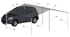
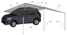
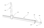
Fig. 1 is an embodiment in which a large-size tarpaulin is installed according to the present invention.
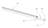
FIG. 2 is a view for explaining the combination of the
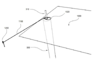
3 is a view for explaining the vertical
Fig. 4 shows an embodiment in which a mini tarp is installed in the present invention.
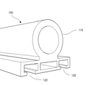
5 is a view for explaining the cross-sectional structure of the
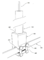
6 is a detailed view for explaining the structure of the
7 is a view for explaining a
Fig. 8 is a view for explaining an example of mounting suitable for a vehicle according to the present invention.
Fig. 9 is another embodiment in which a large tarpaulin is installed according to the present invention.
Fig. 10 shows another embodiment in which the large-size tarp already held by the present invention is installed.
Fig. 11 shows another embodiment in which a large tarpaulin is installed according to the present invention.
12 is a detailed view for explaining the structure of the
13 is an explanatory diagram of a configuration in which the present invention is implemented in a folding type.
14 is an exemplary diagram that variously modifies the cross-sectional structure of the
Hereinafter, preferred embodiments of the present invention will be described in detail with reference to the accompanying drawings. It should be noted that the same components are denoted by the same reference numerals as possible in the accompanying drawings.
In addition, terms and words used in the present specification and claims should not be construed as limited to ordinary or dictionary terms and should be construed in accordance with the technical concept of the present invention. The detailed description of the air structure and the function which are considered to be unnecessarily blurred from the gist of the present invention will be omitted.
A key concept of the present invention is to install a tarp awning adjacent to the vehicle using a vertical pole mounted on the top of the vehicle. It is also possible to install a tarp tarpaulin adjacent to the vehicle using a structural profile horizontally installed on top of the vehicle
The first embodiment of the present invention is an embodiment in which a tarp is installed (adjacent to a vehicle) by using a vertical pole provided on an upper portion of the vehicle. Hereinafter, a first embodiment of the present invention will be described in detail with reference to FIGS. 1 to 3. FIG.
Referring to FIG. 1, the tarp for a vehicle according to the present invention includes a
Here, the portion of the tarpaulin tied to the vehicle upper
In the case of a tarp tent which is installed horizontally without a ridge, the structure (vertical pole) is damaged by the weight of the water due to the precipitation phenomenon in the middle in case of rainy weather, or the water is poured, There was a problem that the water splashed on the bottom of the tarp tent.
However, according to the present invention, the
An embodiment of the
The
Hereinafter, an embodiment of a method of coupling the
First, the vertical
Therefore, according to the present invention, it is possible to install the tarpaulins of various sizes and provide a flexible space of rest, and the structure with the
The first embodiment of the present invention has been described in detail above.
The second embodiment of the present invention is an embodiment in which a structural profile is fixed to an upper portion of a vehicle and tarp is installed adjacent to the vehicle.
Referring to FIG. 4, a tarp for a vehicle according to the present invention includes a
At this time, the
5, the cross-sectional structure of the
6, a method of joining the
Also, at the other end of the length-extending
At this time, the tarpaulin is fixed to the
Referring to Fig. 7, the length-extending
The length-extending
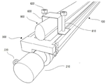
8, a description will be given of a method of fixing the
If the length of the
With the present embodiment, it is possible to provide a rest space of a flexible size, which can be installed in various sizes of tarpaulins, and a tarp for a car which is installed more simply and quickly with the use of the minimum
The second embodiment of the present invention has been described in detail above
This embodiment is an example constructed by combining the first embodiment and the second embodiment described in detail above. Hereinafter, a third embodiment of the present invention will be described in detail with reference to FIGS. 9 to 12. FIG.
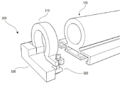
Fig. 9 is an exploded perspective view showing a vehicle upper
10 shows a vehicle upper
11 shows a vehicle upper
The third embodiment of the present invention has been described in detail.
In the first and third embodiments of the present invention, the vertical
It is also obvious to those skilled in the art that a magnetic adsorber or vacuum adsorber can be installed on top of the vehicle and the
It is also obvious to those skilled in the art that the
In addition, in the first to third embodiments of the present invention, the inner shape of the cross section of the
While the present invention has been described with reference to exemplary embodiments, it is to be understood that the invention is not limited to the disclosed exemplary embodiments. Therefore, the embodiments of the present invention disclosed in the present specification and drawings are merely illustrative of the technical contents of the present invention, and are intended to illustrate specific examples in order to facilitate understanding of the present invention, and do not limit the scope of the present invention.
100: structural profile
110: Profile cavity rail
120: Profile fixing bolt groove
200: extension pipe
210: Long extension pipe termination plug
220: Tarpaulin fixing ring
300: Extension of pipe length
310: Extension pipe extension
320: Extend the length of the pipe clamp screw
330: Length extension pipe fixture base
400: Vertical pole join block
410: vertical pole joining block joining groove
420: vertical pole joining block vertical pole joining hole
430: Vertical pole joining fixing bracket
440: Vertical pole fastening bolt
500: vertical poles (500a-500f)
510: pin for fixing tar
520: vertical pole joining block joining portion
600: "ㄷ" folded
610: Fixing bolt
620: Fixing nut
900: Vehicle rail bar
1000: Tarpauling tent
1010: Tarn ridges 1010a to 1010b
1020: Tharp Eyelet hole
1100: String for tarp fixing
1200: Tarp fixing peck
Claims (7)
A tarp tarp forming a shade;
Equipment mounted on the top of the vehicle;
And a plurality of vertical poles coupled to the edges of the tarpaulin,
Characterized in that one of said plurality of vertical poles is a vertical pole (top of vehicle) attached to said fixture
A tarp tarp forming a shade;
A plurality of vertical poles engaged with the edges of the tarpaulin;
Equipment mounted on the top of the vehicle;
A structural profile fixed to the fixture;
A length extending pipe (structural profile) fastened to the structural profile; And,
Wherein the structural profile and the length-extending pipe joint are coupled to the coupling of the tarpaulin using both ends of the length-extension pipe combination.
A tarp tarp forming a shade;
A plurality of vertical poles engaged with the edges of the tarpaulin;
Equipment mounted on the top of the vehicle;
A structural profile fixed to the fixture;
A length extending pipe (structural profile) fastened to the structural profile; And,
Wherein one of the plurality of vertical poles is a vertical pole (vehicle upper) attached to the fixture and is coupled to a coupling of the tarpaulin using both the structural profile and both ends of the elongate pipe joint; Tarp.
Characterized in that the device is a rail bar, a horizontal bar, a magnetic adsorber or a vacuum adsorber mechanism.
Said structural profile and said length extension pipe being connected in either a hinge or slide manner; Features a car tar.
Wherein the structural profile has voids and one side of the structural profile has a slit through which the head of the bolt can be inserted; And the car tar
Priority Applications (1)
| Application Number | Priority Date | Filing Date | Title |
|---|---|---|---|
| KR1020140137061A KR20160042723A (en) | 2014-10-11 | 2014-10-11 | Tarp for vehicle |
Applications Claiming Priority (1)
| Application Number | Priority Date | Filing Date | Title |
|---|---|---|---|
| KR1020140137061A KR20160042723A (en) | 2014-10-11 | 2014-10-11 | Tarp for vehicle |
Publications (1)
| Publication Number | Publication Date |
|---|---|
| KR20160042723A true KR20160042723A (en) | 2016-04-20 |
Family
ID=55917459
Family Applications (1)
| Application Number | Title | Priority Date | Filing Date |
|---|---|---|---|
| KR1020140137061A KR20160042723A (en) | 2014-10-11 | 2014-10-11 | Tarp for vehicle |
Country Status (1)
| Country | Link |
|---|---|
| KR (1) | KR20160042723A (en) |
Cited By (5)
| Publication number | Priority date | Publication date | Assignee | Title |
|---|---|---|---|---|
| KR102299800B1 (en) * | 2020-06-18 | 2021-09-08 | 송한수 | Awning apparatus for vehicle |
| KR200494358Y1 (en) * | 2020-04-17 | 2021-09-27 | 송한수 | Foldable awning frame for a vehicle |
| KR20220112970A (en) | 2021-02-05 | 2022-08-12 | 박종훈 | Car tarp holder |
| KR20220159600A (en) | 2021-05-26 | 2022-12-05 | 박종훈 | vehicle tarp installation structure |
| KR102519392B1 (en) | 2022-08-19 | 2023-04-10 | 권주현 | Corner screen for vehicle earnings |
-
2014
- 2014-10-11 KR KR1020140137061A patent/KR20160042723A/en not_active Application Discontinuation
Cited By (5)
| Publication number | Priority date | Publication date | Assignee | Title |
|---|---|---|---|---|
| KR200494358Y1 (en) * | 2020-04-17 | 2021-09-27 | 송한수 | Foldable awning frame for a vehicle |
| KR102299800B1 (en) * | 2020-06-18 | 2021-09-08 | 송한수 | Awning apparatus for vehicle |
| KR20220112970A (en) | 2021-02-05 | 2022-08-12 | 박종훈 | Car tarp holder |
| KR20220159600A (en) | 2021-05-26 | 2022-12-05 | 박종훈 | vehicle tarp installation structure |
| KR102519392B1 (en) | 2022-08-19 | 2023-04-10 | 권주현 | Corner screen for vehicle earnings |
Similar Documents
| Publication | Publication Date | Title |
|---|---|---|
| KR20160042723A (en) | Tarp for vehicle | |
| US10113330B2 (en) | Expandable mat-based sun shelter | |
| US7472666B1 (en) | Support frame for tarpaulin used for sheltering boats and other objects | |
| US20180038128A1 (en) | Canopy with detachable awning | |
| US9051756B1 (en) | Collapsible sunshade | |
| US20050194030A1 (en) | Shelter having an extendable roof | |
| KR101705442B1 (en) | A ponding-water-proof high-dome tent | |
| US20110259768A1 (en) | Convertible shipping container | |
| US20190112832A1 (en) | Modular canopy structures that can be fitted with a retractable roof, production methods, assembly methods and corresponding uses | |
| KR20120110104A (en) | Auxiliary member | |
| US20060180729A1 (en) | Leg support | |
| KR200471065Y1 (en) | Length adjusting tarp | |
| KR20210135699A (en) | Sunshield device for vehicle | |
| CN210264140U (en) | Folding tent support and roof tent | |
| US7866740B2 (en) | Roof frame and cover system for recreational vehicles | |
| US20020108647A1 (en) | Tent with awning | |
| KR101742476B1 (en) | Tent Mongolian tent-shaped prefabricated | |
| KR100725840B1 (en) | Structure of tent | |
| KR101881112B1 (en) | Tent | |
| KR200314973Y1 (en) | A Connector of Tent Pole | |
| US20140166062A1 (en) | Tent system and methods | |
| JP6606324B2 (en) | Roof structure and roof construction method | |
| EP2025555A2 (en) | Bar for fixing a sidewall of a front tent of a camper, motorhome or the like | |
| KR102496602B1 (en) | Support pole assembly for vehicle installation of camping tarp | |
| CN220769050U (en) | Outdoor waterproof tent |
Legal Events
| Date | Code | Title | Description |
|---|---|---|---|
| WITN | Withdrawal due to no request for examination |