KR20160000728A - Lens moving unit and camera module including the same - Google Patents
Lens moving unit and camera module including the same Download PDFInfo
- Publication number
- KR20160000728A KR20160000728A KR1020140078294A KR20140078294A KR20160000728A KR 20160000728 A KR20160000728 A KR 20160000728A KR 1020140078294 A KR1020140078294 A KR 1020140078294A KR 20140078294 A KR20140078294 A KR 20140078294A KR 20160000728 A KR20160000728 A KR 20160000728A
- Authority
- KR
- South Korea
- Prior art keywords
- housing
- coil
- bobbin
- magnet
- support
- Prior art date
Links
Images


Classifications
-
- G—PHYSICS
- G03—PHOTOGRAPHY; CINEMATOGRAPHY; ANALOGOUS TECHNIQUES USING WAVES OTHER THAN OPTICAL WAVES; ELECTROGRAPHY; HOLOGRAPHY
- G03B—APPARATUS OR ARRANGEMENTS FOR TAKING PHOTOGRAPHS OR FOR PROJECTING OR VIEWING THEM; APPARATUS OR ARRANGEMENTS EMPLOYING ANALOGOUS TECHNIQUES USING WAVES OTHER THAN OPTICAL WAVES; ACCESSORIES THEREFOR
- G03B3/00—Focusing arrangements of general interest for cameras, projectors or printers
- G03B3/10—Power-operated focusing
-
- G—PHYSICS
- G03—PHOTOGRAPHY; CINEMATOGRAPHY; ANALOGOUS TECHNIQUES USING WAVES OTHER THAN OPTICAL WAVES; ELECTROGRAPHY; HOLOGRAPHY
- G03B—APPARATUS OR ARRANGEMENTS FOR TAKING PHOTOGRAPHS OR FOR PROJECTING OR VIEWING THEM; APPARATUS OR ARRANGEMENTS EMPLOYING ANALOGOUS TECHNIQUES USING WAVES OTHER THAN OPTICAL WAVES; ACCESSORIES THEREFOR
- G03B5/00—Adjustment of optical system relative to image or object surface other than for focusing
-
- G—PHYSICS
- G02—OPTICS
- G02B—OPTICAL ELEMENTS, SYSTEMS OR APPARATUS
- G02B27/00—Optical systems or apparatus not provided for by any of the groups G02B1/00 - G02B26/00, G02B30/00
- G02B27/64—Imaging systems using optical elements for stabilisation of the lateral and angular position of the image
- G02B27/646—Imaging systems using optical elements for stabilisation of the lateral and angular position of the image compensating for small deviations, e.g. due to vibration or shake
-
- H—ELECTRICITY
- H02—GENERATION; CONVERSION OR DISTRIBUTION OF ELECTRIC POWER
- H02K—DYNAMO-ELECTRIC MACHINES
- H02K11/00—Structural association of dynamo-electric machines with electric components or with devices for shielding, monitoring or protection
- H02K11/20—Structural association of dynamo-electric machines with electric components or with devices for shielding, monitoring or protection for measuring, monitoring, testing, protecting or switching
- H02K11/21—Devices for sensing speed or position, or actuated thereby
-
- H—ELECTRICITY
- H02—GENERATION; CONVERSION OR DISTRIBUTION OF ELECTRIC POWER
- H02K—DYNAMO-ELECTRIC MACHINES
- H02K33/00—Motors with reciprocating, oscillating or vibrating magnet, armature or coil system
- H02K33/02—Motors with reciprocating, oscillating or vibrating magnet, armature or coil system with armatures moved one way by energisation of a single coil system and returned by mechanical force, e.g. by springs
-
- H—ELECTRICITY
- H04—ELECTRIC COMMUNICATION TECHNIQUE
- H04N—PICTORIAL COMMUNICATION, e.g. TELEVISION
- H04N23/00—Cameras or camera modules comprising electronic image sensors; Control thereof
- H04N23/60—Control of cameras or camera modules
- H04N23/68—Control of cameras or camera modules for stable pick-up of the scene, e.g. compensating for camera body vibrations
- H04N23/682—Vibration or motion blur correction
- H04N23/685—Vibration or motion blur correction performed by mechanical compensation
- H04N23/687—Vibration or motion blur correction performed by mechanical compensation by shifting the lens or sensor position
-
- G—PHYSICS
- G03—PHOTOGRAPHY; CINEMATOGRAPHY; ANALOGOUS TECHNIQUES USING WAVES OTHER THAN OPTICAL WAVES; ELECTROGRAPHY; HOLOGRAPHY
- G03B—APPARATUS OR ARRANGEMENTS FOR TAKING PHOTOGRAPHS OR FOR PROJECTING OR VIEWING THEM; APPARATUS OR ARRANGEMENTS EMPLOYING ANALOGOUS TECHNIQUES USING WAVES OTHER THAN OPTICAL WAVES; ACCESSORIES THEREFOR
- G03B2205/00—Adjustment of optical system relative to image or object surface other than for focusing
- G03B2205/0007—Movement of one or more optical elements for control of motion blur
-
- H—ELECTRICITY
- H02—GENERATION; CONVERSION OR DISTRIBUTION OF ELECTRIC POWER
- H02K—DYNAMO-ELECTRIC MACHINES
- H02K2203/00—Specific aspects not provided for in the other groups of this subclass relating to the windings
- H02K2203/12—Machines characterised by the bobbins for supporting the windings
Abstract
Description
실시 예는 렌즈 구동 장치 및 이를 포함하는 카메라 모듈에 관한 것이다.Embodiments relate to a lens driving apparatus and a camera module including the lens driving apparatus.
초소형, 저전력 소모를 위한 카메라 모듈은 기존의 일반적인 카메라 모듈에 사용된 보이스 코일 모터(VCM:Voice Coil Motor)의 기술을 적용하기 곤란하여, 이와 관련 연구가 활발히 진행되어 왔다.It is difficult to apply the technology of a voice coil motor (VCM) used in a conventional camera module to a camera module for ultra small size and low power consumption, and related research has been actively conducted.
스마트폰과 같은 소형 전자제품에 실장되는 카메라 모듈의 경우, 사용 도중에 빈번하게 카메라 모듈이 충격을 받을 수 있으며, 촬영하는 동안 사용자의 손떨림 등에 따라 미세하게 카메라 모듈이 흔들릴 수 있다. 이와 같은 점을 감안하여, 최근에는 손떨림 방지 수단을 카메라 모듈에 추가 설치하는 기술에 대한 개발이 요구되고 있다.In the case of a camera module mounted on a small electronic device such as a smart phone, the camera module may be frequently hit during use, and the camera module may be slightly shaken due to user's hand motion during shooting. In view of this, in recent years, there has been a demand for development of a technique for additionally installing the camera shake preventing means on the camera module.
이러한 손떨림 방지 수단은 다양하게 연구되고 있는데, 그 중 하나로서 광학모듈을 광축에 대하여 수직한 평면에 해당되는 x축 및 y축으로 움직여 손떨림을 보정할 수 있는 기술이 있다. 이 기술의 경우, 이미지 보정을 위해 광학계를 광축과 수직인 평면 내에서 이동 조정하므로 구조가 복잡하고 소형화에 적합하지 않다.One such technique is to move the optical module along the x-axis and the y-axis corresponding to the plane perpendicular to the optical axis to correct the camera shake. In this technique, the optical system is moved and adjusted in a plane perpendicular to the optical axis for image correction, so that the structure is complicated and is not suitable for miniaturization.
또한, 광학 모듈의 초점을 정확하게 맞추기 위해서, 광축으로 이동하는 광학 모듈의 위치를 센싱하는 별도의 센서가 요망되며, 이 센서를 회로 기판과 전기적으로 연결시키기 위한 방법이 필요성이 대두되고 있다.In addition, in order to accurately focus the optical module, a separate sensor for sensing the position of the optical module moving to the optical axis is desired, and a method for electrically connecting the sensor to the circuit board is required.
실시 예는 공정을 간소화시키고 간단한 구성으로 보다 정확하게 렌지의 초점을 조정할 수 있도록 하는 렌즈 구동 장치를 제공한다.The embodiment provides a lens driving apparatus that simplifies the process and makes it possible to more accurately adjust the focus of the stove in a simple configuration.
실시 예에 의한 렌즈 구동 장치는, 적어도 한 장 이상의 렌즈가 내측에 설치되고 외주면에는 제1 코일이 설치된 보빈; 상기 보빈의 주변에 상기 제1 코일과 대향하여 배치된 제1 마그네트; 상기 제1 마그네트를 지지하는 하우징; 및 상기 보빈 및 상기 하우징과 결합되는 상측 및 하측 탄성 부재 포함하여, 상기 제1 마그네트와 상기 제1 코일의 상호 작용에 의해 상기 보빈을 광축에 평행한 제1 방향으로 이동 시키는 제1 렌즈 구동 유닛; 및 상기 제1 렌즈 구동 유닛과 일정 간격 이격 배치되는 베이스; 상기 하우징을 상기 베이스에 대하여 상기 제1 방향에 직교하는 제2 및 제3 방향으로 이동 가능하게 지지하는 복수의 지지 부재 쌍; 상기 제1 마그네트에 대향하여 배치된 제2 코일; 및 상기 제2 코일이 설치되는 회로 기판을 포함하여, 상기 제1 마그네트와 상기 제2 코일의 상호 작용에 의해 상기 하우징을 상기 제2 및 제3 방향으로 이동시키는 제2 렌즈 구동 유닛을 포함하고, 상기 복수의 지지 부재 쌍은 상기 하우징의 측면에 배치되고, 상기 복수의 지지 부재 쌍 각각은 서로 분할되어 상기 하우징의 동일 측면에서 인접하여 배치된 제1 및 제2 지지 부재를 포함하고, 상기 복수의 지지 부재 쌍 중 하나인 제1 지지 부재 쌍을 통해 상기 제1 코일에 전원을 공급할 수 있다.A lens driving apparatus according to an embodiment of the present invention includes: a bobbin having at least one lens disposed on an inner side and a first coil on an outer peripheral surface; A first magnet disposed on the periphery of the bobbin so as to face the first coil; A housing for supporting the first magnet; And a first lens driving unit for moving the bobbin in a first direction parallel to the optical axis by interaction between the first magnet and the first coil, the upper and lower elastic members being coupled to the bobbin and the housing. And a base disposed at a predetermined distance from the first lens driving unit; A plurality of support member pairs movably supporting the housing with respect to the base in a second direction and a third direction orthogonal to the first direction; A second coil disposed opposite the first magnet; And a second lens driving unit including a circuit board on which the second coil is mounted and moving the housing in the second and third directions by an interaction between the first magnet and the second coil, Wherein the plurality of support member pairs are disposed on a side surface of the housing and each of the plurality of support member pairs includes first and second support members which are separated from each other to be disposed adjacent to the same side of the housing, Power can be supplied to the first coil through the first pair of support members, which is one of the pair of support members.
상기 하우징의 복수의 측면은 복수의 상기 제1 마그네트가 설치되는 모서리에 마련된 복수의 제1 면; 및 상기 복수의 제1 면이 상호 연결되며, 일정 깊이의 평면으로 형성되어 상기 복수의 지지 부재 쌍 각각이 배치된 제2 면을 포함할 수 있다.A plurality of side surfaces of the housing include a plurality of first surfaces provided at corners where a plurality of the first magnets are installed; And a second surface interconnected by the plurality of first surfaces, the second surface being formed in a plane having a predetermined depth and each of the plurality of pairs of support members being disposed.
상기 상측 탄성 부재는 서로 분할된 제1 및 제2 상측 탄성 부재를 포함하고, 상기 제1 및 제2 상측 탄성 부재는 상기 제1 지지 부재 쌍의 상기 제1 및 제2 지지 부재와 각각 대향하면서 연결되어 상기 전원을 상기 제1 코일에 공급할 수 있다.Wherein the upper elastic member includes first and second upper elastic members that are separated from each other, wherein the first and second upper elastic members are connected to each other while facing the first and second support members of the first pair of support members, So that the power can be supplied to the first coil.
상기 제1 및 제2 상측 탄성 부재 각각은 상기 보빈과 결합하는 내측 프레임; 상기 하우징과 결합하는 외측 프레임; 상기 내측 프레임과 상기 외측 프레임을 연결하는 프레임 연결부; 및 상기 외측 프레임으로부터 돌출되어 상기 제1 지지 부재 쌍의 상기 제1 또는 제2 지지 부재와 대향하는 지지 부재 접촉부를 포함할 수 있다.Wherein each of the first and second upper elastic members has an inner frame coupled with the bobbin; An outer frame coupled with the housing; A frame connector connecting the inner frame and the outer frame; And a support member contact protruding from the outer frame and opposed to the first or second support member of the first pair of support members.
상기 제1 렌즈 구동 유닛은 상기 하우징에 의해 지지되어, 상기 보빈의 상기 제1 방향의 위치를 검출하는 제1 감지 센서; 및 상기 제1 감지 센서와 대향하도록 상기 보빈의 외주면에 부착되는 제2 마그네트를 더 포함할 수 있다. 상기 제2 마그네트는 상기 보빈의 원주 방향으로 이격된 복수의 상기 제1 마그네트 사이에 배치될 수 있다. 상기 제1 감지 센서는 상기 하우징에 삽입되어 지지될 수도 있고, 상기 하우징에 부착되어 지지될 수도 있다. The first lens driving unit includes: a first sensing sensor supported by the housing and detecting a position of the bobbin in the first direction; And a second magnet attached to an outer circumferential surface of the bobbin to face the first sensing sensor. The second magnet may be disposed between a plurality of the first magnets spaced apart in the circumferential direction of the bobbin. The first sensing sensor may be inserted into the housing and supported by the housing.
상기 하측 탄성 부재는 서로 분할된 제1 및 제2 하측 탄성 부재를 포함하고, 상기 제1 감지 센서의 복수 핀 중 일부인 제1 핀은 상기 복수의 지지 부재 쌍 중 다른 하나인 제2 지지 부재 쌍을 통해 상기 회로 기판과 연결되고, 상기 제1 감지 센서의 상기 복수 핀 중 타부인 제2 핀은 상기 제1 및 제2 하측 탄성 부재와 상기 복수의 지지 부재 쌍 중 또 다른 하나인 제3 지지 부재 쌍을 통하여 상기 회로 기판과 연결될 수 있다.Wherein the lower elastic member includes first and second lower elastic members that are separated from each other, and a first pin, which is a part of the plurality of fins of the first sensing sensor, includes a second pair of support members, And a second pin of the plurality of pins of the first sensing sensor is connected to the circuit board through a third pair of the first and second lower elastic members and a third one of the plurality of pairs of support members, To the circuit board.
상기 제1 및 제2 하측 탄성 부재 각각은 상기 보빈과 결합되는 내측 프레임;상기 하우징과 결합되는 외측 프레임; 상기 내측 프레임과 상기 외측 프레임을 연결하는 프레임 연결부; 및 상기 제1 감지 센서의 상기 제2 핀과 접촉 가능하고, 상기 제3 지지 부재 쌍과 접촉 가능하도록, 상기 외측 프레임으로부터 돌출된 적어도 하나의 센서 접촉부를 포함할 수 있다.Each of the first and second lower elastic members includes an inner frame coupled with the bobbin, an outer frame coupled with the housing, A frame connector connecting the inner frame and the outer frame; And at least one sensor contact protruding from the outer frame to be contactable with the second pin of the first sensing sensor and to be contactable with the third pair of support members.
상기 제2 지지 부재 쌍과 상기 제3 지지 부재 쌍은 서로 대향하여 배치될 수 있다.The pair of second support members and the pair of third support members may be disposed opposite to each other.
상기 제1 렌즈 구동 유닛은 상기 보빈의 중심을 기준으로 상기 제2 마그네트와 대칭인 상기 보빈의 외주면에 배치되는 자장 보상용 금속을 더 포함할 수 있다.The first lens driving unit may further include a magnetic field compensating metal disposed on an outer circumferential surface of the bobbin symmetrical to the second magnet with respect to a center of the bobbin.
상기 제1 및 제2 지지 부재는 상기 제1 방향에 수직한 방향으로 서로 대칭인 형상을 가질 수 있다.The first and second support members may have a shape symmetrical to each other in a direction perpendicular to the first direction.
상기 제1 및 제2 지지 부재 각각은 상기 하우징의 상기 제2 면의 상단부와 결합된 상측 단자부; 상기 상측 단자부로부터 길이 방향으로 연장되어 적어도 1회 이상 구부러진 형상을 갖는 적어도 하나의 탄성 변형부; 및 상기 적어도 하나의 탄성 변형부로부터 연장되어 상기 베이스와 결합된 하측 단자부를 포함할 수 있다.Each of the first and second support members includes an upper terminal portion coupled with an upper end portion of the second surface of the housing; At least one elastic deforming portion extending in the longitudinal direction from the upper terminal portion and having a shape bent at least once more; And a lower terminal portion extending from the at least one elastic deformation portion and coupled with the base.
상기 제1 지지 부재 쌍에서, 상기 제1 지지 부재의 상기 상측 단자부는 상기 제1 상측 탄성 부재와 전기적으로 연결되고, 상기 제2 지지 부재의 상기 상측 단자부는 상기 제2 상측 탄성 부재와 전기적으로 연결될 수 있다.In the pair of first support members, the upper terminal portion of the first support member is electrically connected to the first upper elastic member, and the upper terminal portion of the second support member is electrically connected to the second upper elastic member .
상기 제2 지지 부재 쌍에서, 상기 제1 지지 부재의 상기 상측 단자부는 상기 제1 감지 센서의 상기 제1 핀 중 하나인 제1-1 핀과 연결되고 상기 제2 지지 부재의 상기 상측 단자부는 상기 제1 감지 센서의 상기 제1 핀 중 다른 하나인 제1-2 핀과 연결될 수 있다.In the pair of second support members, the upper terminal portion of the first support member is connected to the 1-1 pin, which is one of the first pins of the first sensing sensor, and the upper terminal portion of the second support member is connected to the And may be connected to the other one of the first pins of the first sensing sensor.
상기 제1 감지 센서의 상기 제2 핀 중 하나인 제2-1 핀은 상기 제1 하측 탄성 부재의 일측과 연결되고, 상기 제2 핀 중 다른 하나인 제2-2 핀은 상기 제2 하측 탄성 부재의 일측와 연결되고, 상기 제3 지지 부재 쌍에서, 상기 제1 지지 부재는 상기 제1 하측 탄성 부재의 타측과 연결되고 제2 지지 부재는 상기 제2 하측 탄성 부재의 타측과 연결될 수 있다.And a second 2-1 pin which is one of the second pins of the first sensing sensor is connected to one side of the first lower elastic member and a second 2-2 pin which is another one of the second pins is connected to the second lower elasticity member, And in the third pair of support members, the first support member may be connected to the other side of the first lower elastic member, and the second support member may be connected to the other side of the second lower elastic member.
상기 회로 기판은 상기 복수의 지지 부재 쌍 각각의 상기 하측 단자부와 연결 가능한 패드부를 포함할 수 있다.The circuit board may include a pad portion connectable with the lower terminal portion of each of the plurality of pairs of support members.
다른 실시 예에 의한 카메라 모듈은, 이미지 센서; 상기 이미지 센서가 실장된 인쇄회로 기판; 및 상기 렌즈 구동 장치를 포함할 수 있다.A camera module according to another embodiment includes an image sensor; A printed circuit board on which the image sensor is mounted; And the lens driving device.
실시 예에 따른 렌즈 구동 장치는 기존과 달리, 서로 전기적으로 분리된 제1 및 제2 지지 부재와 제1 및 제2 상부 탄성 부재를 하우징의 동일한 평면상에서 대향하여 연결시키므로 솔더링 공정에 소요되는 시간을 단축하면서 제조 공정 시간을 단축시킬 수 있고,Since the first and second supporting members electrically separated from each other and the first and second upper elastic members are opposed to each other on the same plane of the housing, the lens driving apparatus according to the embodiment of the present invention can reduce the time required for the soldering process The manufacturing process time can be shortened,
하우징의 각 측면을 바라보는 하나의 지지 부재를 2개로 분할하고 하부 탄성 부재를 2개로 분할하여, 분할된 지지 부재와 분할된 하부 탄성 부재를 이용하여 제1 감지 센서를 회로 기판에 연결시킬 수 있기 때문에 제1 감지 센서를 위한 별도의 구조가 요구되지 않으므로, 보빈의 위치를 정확하게 제어하기 위한 제1 감지 센서(170)를 저렴한 비용으로 추가할 수 있고,It is possible to divide one supporting member facing each side of the housing into two, divide the lower elastic member into two, connect the first sensing sensor to the circuit board by using the divided supporting member and the divided lower elastic member Therefore, since a separate structure for the first sensing sensor is not required, the
추가되는 제1 감지 센서에서 감지된 값을 궤환시켜 렌즈의 초점이 정확하게 조절될 수 있도록 한다.And the value detected by the added first sensing sensor is fed back so that the focus of the lens can be accurately adjusted.
도 1은 실시 예에 의한 렌즈 구동 장치의 개략적인 사시도를 나타낸다.
도 2는 도 1에 예시된 렌즈 구동 장치의 분해 사시도를 나타낸다.
도 3은 도 1 및 도 2에 예시된 커버 부재를 제거한 실시 예에 의한 렌즈 구동 장치의 사시도를 나타낸다.
도 4는 실시 예에 의한 렌즈 구동 장치에서, 보빈, 제1 코일, 제1 마그네트, 제1 감지 센서, 및 제2 마그네트가 결합된 사시도를 나타낸다.
도 5는 실시 예에 의한 렌즈 구동 장치에서, 보빈, 제1 마그네트, 제1 감지 센서, 제2 마그네트, 및 자장 보상용 금속이 결합된 평면도를 나타낸다.
도 6은 실시 예에 의한 하우징과 제1 감지 센서의 분해 사시도를 나타낸다.
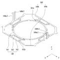
도 7은 실시 예에 의한 하우징의 배면 사시도를 나타낸다.
도 8은 실시 예에 의한 보빈, 제1 마크네트, 하우징, 하측 탄성 부재, 및 복수의 지지 부재 쌍이 결합된 배면 사시도를 나타낸다.
도 9는 실시 예에 의한 상부 탄성 부재의 사시도를 나타낸다.
도 10은 실시 예에 의한 하측 탄성 부재의 사시도를 나타낸다.
도 11은 도 3에 도시된 I-I' 선을 따라 절개한 단면도를 나타낸다.
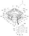
도 12는 실시 예에 의한 제2 코일, 회로 기판 및 베이스의 부분 결합 사시도를 나타낸다.
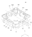
도 13은 실시 예에 의한 제2 코일, 회로 기판 및 베이스의 분해 사시도를 나타낸다.
도 14는 실시 예에 의한 복수의 지지 부재 쌍 각각의 정면도를 나타낸다.
도 15는 실시 예에 의한 회로 기판의 사시도를 나타낸다.
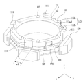
도 16은 도 3에 예시된 렌즈 구동 장치에서 하측 탄성 부재, 제1 내지 제4 지지 부재 쌍 및 회로 기판만의 실시 예에 의한 사시도를 나타낸다.1 is a schematic perspective view of a lens driving apparatus according to an embodiment.
2 is an exploded perspective view of the lens driving apparatus illustrated in Fig.
FIG. 3 is a perspective view of a lens driving apparatus according to an embodiment in which the cover member illustrated in FIGS. 1 and 2 is removed.
FIG. 4 is a perspective view of a lens driving apparatus according to an embodiment in which a bobbin, a first coil, a first magnet, a first sensing sensor, and a second magnet are coupled.
FIG. 5 is a plan view in which a bobbin, a first magnet, a first sensing sensor, a second magnet, and a metal for magnetic field compensation are combined in the lens driving apparatus according to the embodiment.
6 is an exploded perspective view of the housing and the first sensing sensor according to the embodiment.
7 is a rear perspective view of the housing according to the embodiment.
FIG. 8 is a rear perspective view of a bobbin, a first mark net, a housing, a lower elastic member, and a plurality of support member pairs according to the embodiment.
9 is a perspective view of the upper elastic member according to the embodiment.
10 is a perspective view of the lower elastic member according to the embodiment.
11 is a cross-sectional view taken along the line II 'shown in FIG.
12 is a partially assembled perspective view of a second coil, a circuit board and a base according to the embodiment.
13 is an exploded perspective view of a second coil, a circuit board and a base according to the embodiment.
14 shows a front view of each of a plurality of pairs of support members according to the embodiment.
15 shows a perspective view of a circuit board according to an embodiment.
Fig. 16 is a perspective view showing an embodiment of the lower elastic member, the first to fourth support member pairs, and the circuit board alone in the lens driving apparatus illustrated in Fig. 3;
이하, 본 발명을 구체적으로 설명하기 위해 실시 예를 들어 설명하고, 발명에 대한 이해를 돕기 위해 첨부도면을 참조하여 상세하게 설명하기로 한다. 그러나, 본 발명에 따른 실시 예들은 여러 가지 다른 형태로 변형될 수 있으며, 본 발명의 범위가 아래에서 상술하는 실시 예들에 한정되는 것으로 해석되지 않아야 한다. 본 발명의 실시 예들은 당 업계에서 평균적인 지식을 가진 자에게 본 발명을 보다 완전하게 설명하기 위해서 제공되는 것이다.DETAILED DESCRIPTION OF THE PREFERRED EMBODIMENTS Hereinafter, embodiments of the present invention will be described in detail with reference to the accompanying drawings in order to facilitate understanding of the present invention. However, the embodiments according to the present invention can be modified into various other forms, and the scope of the present invention should not be construed as being limited to the embodiments described below. Embodiments of the present invention are provided to more fully describe the present invention to those skilled in the art.
본 발명에 따른 실시 예의 설명에 있어서, 각 element의 " 상(위)" 또는 "하(아래)(on or under)"에 형성되는 것으로 기재되는 경우에 있어, 상(위) 또는 하(아래)(on or under)는 두개의 element가 서로 직접(directly)접촉되거나 하나 이상의 다른 element가 상기 두 element사이에 배치되어(indirectly) 형성되는 것을 모두 포함한다. 또한 “상(위)" 또는 "하(아래)(on or under)”로 표현되는 경우 하나의 element를 기준으로 위쪽 방향뿐만 아니라 아래쪽 방향의 의미도 포함할 수 있다.In the description of the embodiment according to the present invention, in the case of being described as being formed on the "upper" or "on or under" of each element, on or under includes both elements being directly contacted with each other or one or more other elements being indirectly formed between the two elements. Also, when expressed as "on" or "on or under", it may include not only an upward direction but also a downward direction with respect to one element.
또한, 이하에서 이용되는 "제1" 및 "제2," "상/상부/위" 및 "하/하부/아래" 등과 같은 관계적 용어들은, 그런 실체 또는 요소들 간의 어떠한 물리적 또는 논리적 관계 또는 순서를 반드시 요구하거나 내포하지는 않으면서, 어느 한 실체 또는 요소를 다른 실체 또는 요소와 구별하기 위해서만 이용될 수도 있다.It is also to be understood that the terms "first" and "second," "upper / upper / upper," and "lower / lower / lower" But may be used only to distinguish one entity or element from another entity or element, without necessarily requiring or implying an order.
도면에서 각층의 두께나 크기는 설명의 편의 및 명확성을 위하여 과장되거나 생략되거나 또는 개략적으로 도시되었다. 또한 각 구성요소의 크기는 실제크기를 전적으로 반영하는 것은 아니다.The thickness and size of each layer in the drawings are exaggerated, omitted, or schematically shown for convenience and clarity of explanation. Also, the size of each component does not entirely reflect the actual size.
이하, 첨부된 도면을 참조하여 실시 예에 의한 렌즈 구동 장치에 대해 다음과 같이 살펴본다. 설명의 편의상, 실시 예에 의한 렌즈 구동 장치는 데카르트 좌표계(x, y, z)를 사용하여 설명하지만, 다른 좌표계를 사용하여 설명할 수도 있으며, 실시 예는 이에 국한되지 않는다. 각 도면에서 x축과 y축은 광축 방향인 z축에 대하여 수직한 방향을 의미하며, 광축 방향인 z축 방향을 '제1 방향'이라 칭하고, x축 방향을 '제2 방향'이라 칭하고, y축 방향을 '제3 방향'이라 칭할 수 있다.Hereinafter, a lens driving apparatus according to an embodiment will be described with reference to the accompanying drawings. For convenience of explanation, the lens driving apparatus according to the embodiment is described using the Cartesian coordinate system (x, y, z), but may be described using another coordinate system, and the embodiment is not limited to this. In the drawings, the x-axis and the y-axis indicate directions perpendicular to the z-axis, which is the optical axis direction, the z-axis direction as the optical axis direction is referred to as a first direction, the x-axis direction is referred to as a second direction, The axial direction can be referred to as a 'third direction'.
스마트폰 또는 태블릿 PC 등과 같은 모바일 디바이스의 소형 카메라 모듈에 적용되는 '손떨림 보정 장치'란 정지 화상의 촬영 시 사용자의 손떨림에 의해 기인한 진동으로 인해 촬영된 이미지의 외곽선이 또렷하게 형성되지 못하는 것을 방지할 수 있도록 구성된 장치를 의미할 수 있다.The "camera-shake correction device" applied to a small-sized camera module of a mobile device such as a smart phone or a tablet PC is to prevent the outline of the captured image from being formed due to the vibration caused by the hand- ≪ / RTI >
또한, '오토 포커싱 장치'란, 피사체의 화상의 초점을 자동으로 이미지 센서 면에 결상시키는 장치이다. 이와 같은 손떨림 보정 장치와 오토 포커싱 장치는 다양하게 구성할 수 있는데, 실시 예에 의한 렌즈 구동 장치는, 적어도 한 장의 렌즈로 구성된 광학 모듈을 광축에 대해 평행한 제1 방향으로 움직이거나, 제1 방향에 수직인 제2 및 제3 방향에 의해 형성되는 면에 대하여 움직여 손떨림 보정 동작 및/또는 오토 포커싱 동작을 수행할 수 있다.The "auto focusing device" is a device that automatically focuses an image of a subject on an image sensor surface. The camera shake correcting device and the auto focusing device may be configured in various manners. In the lens driving device according to the embodiment, the optical module composed of at least one lens is moved in a first direction parallel to the optical axis, It is possible to perform the camera shake correcting operation and / or the auto focusing operation by moving with respect to the surface formed by the second and third directions perpendicular to the optical axis.
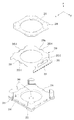
도 1은 실시 예에 의한 렌즈 구동 장치의 개략적인 사시도를 나타내고, 도 2는 도 1에 예시된 렌즈 구동 장치의 분해 사시도를 나타낸다.Fig. 1 shows a schematic perspective view of a lens driving apparatus according to an embodiment, and Fig. 2 shows an exploded perspective view of the lens driving apparatus illustrated in Fig.
도 1 및 도 2를 참조하면, 실시 예에 따른 렌즈 구동 장치는, 제1 렌즈 구동 유닛(100), 제2 렌즈 구동 유닛(200) 및 커버 부재(300)를 포함할 수 있다. 여기서, 제1 렌즈 구동 유닛(100)은 전술한 오토 포커싱 장치의 역할을 수행하고, 제2 렌즈 구동 유닛(200)은 전술한 손떨림 보정 장치의 역할을 수행할 수 있다.Referring to FIGS. 1 and 2, the lens driving apparatus according to the embodiment may include a first
커버 부재(300)는 대략 상자 형태로 마련될 수 있으며, 제1 및 제2 렌즈 구동 유닛(100, 200)을 감쌀 수 있다.The
도 3은 도 1 및 도 2에 예시된 커버 부재(300)를 제거한 실시 예에 의한 렌즈 구동 장치의 사시도를 나타낸다.FIG. 3 is a perspective view of a lens driving apparatus according to an embodiment in which the
제1 렌즈 구동 유닛(100)은 보빈(bobbin)(110), 제1 코일(120), 제1 마그네트(130), 하우징(140), 상부 탄성 부재(150), 및 하부 탄성 부재(160)를 포함할 수 있다. 또한, 제1 렌즈 구동 유닛(100)은 제1 감지 센서(170) 및 제2 마그네트(180)를 더 포함할 수 있으며, 여기에 추가로 자장 보상용 금속(182)을 더 포함할 수도 있다.The first
도 2에서, 복수의 지지 부재 쌍(pair)(220)이 제1 렌즈 구동 유닛(100)에 속하는 것처럼 도시되어 있지만, 복수의 지지 부재 쌍(220)은 기능적으로 보면, 제2 렌즈 구동 유닛(200)에도 속할 수 있다. 지지 부재 쌍(220)에 대해서는 제2 렌즈 구동 유닛(100)을 설명할 때, 상세히 후술된다.2, although a plurality of support member pairs 220 are shown as belonging to the first
도 4는 실시 예에 의한 렌즈 구동 장치에서, 보빈(110), 제1 코일(120), 제1 마그네트(130), 제1 감지 센서(170), 및 제2 마그네트(180)가 결합된 사시도를 나타낸다.4 is a perspective view of a lens driving apparatus according to an embodiment in which a
도 5는 실시 예에 의한 렌즈 구동 장치에서, 보빈(110), 제1 마그네트(130), 제1 감지 센서(170), 제2 마그네트(180), 및 자장 보상용 금속(182)이 결합된 평면도를 나타낸다.5 is a schematic view of a lens driving apparatus according to an embodiment in which a
전술한 도면들을 참조하면, 보빈(110)은 하우징(140)의 내부 공간에 광축 방향인 제1 방향에 대해 평행한 방향으로 왕복 이동 가능하게 설치될 수 있다. 보빈(110)의 외주면에 제1 코일(120)이 도 4에 예시된 바와 같이 설치되어, 제1 코일(120)과 제1 마그네트(130)가 전자기적 상호 작용할 수 있다. 이를 위해, 제1 마그네트(130)는 보빈(110)의 주변에 제1 코일(120)과 대향하여 배치될 수 있다.Referring to the drawings, the
또한, 보빈(110)이 광축과 평행한 제1 방향으로 상승 및/또는 하강하는 동작하여 오토 포커싱 기능을 수행할 때, 상측 및 하측 탄성 부재(150, 160)에 의해 탄력적으로 지지될 수 있다.Further, when the
비록 도시되지는 않았지만, 보빈(110)의 내부의 측면(즉, 내측)에 적어도 한장 이상의 렌즈가 설치될 수 있는 렌즈 배럴(미도시)을 포함할 수 있다. 렌즈 배럴은 보빈(110)의 내측에 다양한 방식으로 설치될 수 있다. 예컨대, 보빈(110)의 내주면에 암 나사산을 형성하고, 렌즈 베럴의 외주면에는 암 나사산에 대응되는 수 나사산을 형성하여 이들의 나사 결합으로 렌즈 베럴을 통해 보빈(110)에 결합할 수 있지만, 실시 예는 이에 국한되지 않는다.(Not shown) in which at least one lens can be installed on the inner side (i.e., the inner side) of the
다른 실시 예에 의하면, 렌즈 배럴을 보빈(110)의 안쪽에 나사 결합 이외의 방법으로 직접 고정되거나 또는, 렌즈 배럴 없이 한 장 이상의 렌즈가 보빈(110)과 일체로 형성될 수도 있다. 렌즈 배럴에 결합되는 렌즈는 한 장으로 구성될 수도 있고, 2개 또는 그 이상의 렌즈들이 광학계를 형성하도록 구성할 수도 있다.According to another embodiment, the lens barrel may be directly fixed to the inside of the
도 6은 실시 예에 의한 하우징(140)과 제1 감지 센서(170)의 분해 사시도를 나타내고, 도 7은 실시 예에 의한 하우징(140)의 배면 사시도를 나타낸다.FIG. 6 is an exploded perspective view of the
보빈(110)은 제1 스토퍼(111) 및 제2 스토퍼(또는, 권선 돌기)(112)를 포함할 수 있다.The
제1 스토퍼(111)는 보빈(110)이 오토 포커싱 기능을 수행하기 위해 광축에 평행한 방향인 제1 방향으로 움직일 때, 외부 충격 등에 의해 규정된 범위 이상으로 움직이더라도, 보빈(110)의 몸체 상측면이 도 1에 도시된 커버 부재(300)의 내측면에 직접 충돌하는 것을 방지할 수 있다.When the
또한, 도 3을 참조하면 제 1 스토퍼(111)는 상측 탄성 부재(150)의 설치 위치를 가이드 하는 역할을 함께 수행할 수도 있다. 실시 예에 따르면, 도 4에 도시된 바와 같이, 제 1 스토퍼(111)는 복수 개가 상측으로 제1 높이(h1)로 돌출 형성될 수 있는데, 적어도 4개가 다각 기둥의 형태로 돌출 형성될 수 있다.Referring to FIG. 3, the
또한, 예시된 바와 같이 제 1 스토퍼(111)는 보빈(110)의 중심에 대해 대칭 구조로 마련될 수도 있고, 예시된 바와 달리 다른 부품들과의 간섭이 배제된 비대칭 구조로 마련될 수도 있다. 이 경우, 도 6에 예시된 바와 같이, 하우징(140)은 제1 스토퍼(111)와 대응되는 위치에 형성된 제1 안착 홈(146-1)을 포함할 수 있다.Also, as illustrated, the
제2 스토퍼(또는, 권선 돌기)(112)는 보빈(110)이 오토 포커싱 기능을 위해 광축에 평행한 방향인 제1 방향으로 움직일 때, 외부 충격 등에 의해 보빈(110)이 규정된 범위 이상으로 움직이더라도, 보빈(110)의 몸체 바닥면이 베이스(210) 및 회로 기판(250)의 상부면에 직접 충돌하는 것을 방지할 수 있다. 도 4의 경우, 제2 스토퍼(112)는 2개의 스토퍼(112a, 112b)를 포함하는 것으로 예시되어 있지만, 실시 예는 제2 스토퍼(112)의 개수에 국한되지 않는다.When the
실시 예에 따르면, 제2 스토퍼(112)는 보빈(110)의 외주면으로부터 원주 방향으로 돌출 형성될 수 있다. 이 경우, 도 6에 예시된 하우징(140)은 제2 스토퍼(112)와 대응되는 위치에 형성된 제2 안착 홈(146-2)을 포함할 수 있다.According to the embodiment, the
도 6을 참조하면, 제1 스토퍼(111)와 제1 안착 홈(146-1)의 제1 바닥면(146a-1)이 접촉된 상태가 초기위치로 구성되면, 오토 포커싱 기능은 기존의 보이스 코일 모터(VCM:Voice Coil Motor)에서의 단방향 제어와 같이 제어될 수 있다. 또는, 제2 스토퍼(112)와 제2 안착 홈(146-2)의 제2 바닥면(146a-2)이 접촉된 상태가 초기위치로 구성되면, 오토 포커싱 기능은 기존의 보이스 코일 모터에서의 단방향 제어와 같이 제어될 수도 있다. 즉, 전류가 제1 코일(120)에 공급될 때 보빈(110)이 상승하고, 전류가 오프될 때 보빈(120)이 하강하는 동작을 통해 오토 포커싱 기능이 구현될 수 있다.Referring to FIG. 6, when the
그러나, 제1 스토퍼(111)와 제1 안착홈(146-1)의 제1 바닥면(146a-1)이 일정 거리 이격된 위치가 초기 위치로 구성되면, 오토 포커싱 기능은 기존의 보이스 코일 모터에서의 양방향 제어와 같이 전류의 방향에 따라 제어될 수 있다. 또는, 제2 스토퍼(112)와 제2 안착홈(146-2)의 제2 바닥면(146a-2)이 일정 거리 이격된 위치가 초기 위치로 구성되면, 오토 포커싱 기능은 기존의 보이스 코일 모터에서의 양방향 제어와 같이 전류의 방향에 따라 제어될 수도 있다. 즉, 보빈(110)을 광축에 평행한 상측 또는 하측 방향으로 움직이는 동작을 통해 오토 포커싱 기능이 구현될 수도 있다. 예를 들면, 정방향 전류가 인가되면 보빈(110)이 상측으로 이동할 수 있으며, 역방향 전류가 인가되면 보빈(110)이 하측으로 이동할 수 있다.However, if the
제1 스토퍼(111)와 대응되는 하우징(140)의 제1 안착홈(146-1)은 오목하게 형성될 수 있다. 이때, 도 4에 도시된 제1 스토퍼(111)의 제1 폭(w1)보다 도 6에 도시된 제1 안착홈(146-1)의 제2 폭(w2)이 일정 공차를 가지도록 형성될 수 있다. 이로 인해, 제1 안착홈(146-1)의 내부에서 제1 스토퍼(111)가 회전하는 것이 규제될 수 있다. 그러면, 보빈(110)이 광축 방향이 아닌 광축을 중심으로 회전하는 방향으로 힘을 받더라도, 제1 스토퍼(111)가 보빈(110)의 회전을 방지할 수 있다. 이러한 제1 스토퍼(111)의 역할을 제2 스토퍼(112)가 수행할 수도 있음은 물론이다.The first seating groove 146-1 of the
도 8은 보빈(110), 제1 마크네트(130), 하우징(140), 하측 탄성 부재(160), 및 복수의 지지 부재 쌍(220)이 결합된 배면 사시도를 나타낸다.8 shows a rear perspective view in which the
보빈(110)의 상부면에는 도 3 및 도 4에 예시된 복수 개의 상측 지지 돌기(113)가 돌출 형성되고, 보빈(110)의 하부면에는 도 8에 예시된 복수의 하측 지지 돌기(114)가 돌출 형성될 수 있다.A plurality of
복수의 상측 지지 돌기(113)는 예시된 바와 같이 반구 형상을 가질 수도 있고, 이와 달리 원통 형상 또는 각기둥 형상을 가질 수도 있으나, 실시 예는 상측 지지 돌기(113)의 형상에 국한되지 않는다. The plurality of
도 9는 실시 예에 의한 상부 탄성 부재(150)의 사시도를 나타낸다.Fig. 9 shows a perspective view of the upper
도 9를 참조하면, 실시 예에 따르면, 상측 탄성 부재(150)는 서로 전기적으로 분할된 제1 상측 탄성 부재(150a) 및 제2 상측 탄성 부재(150b)를 포함할 수 있다. Referring to FIG. 9, the upper
제1 및 제2 상측 탄성 부재(150a, 150b) 각각은 보빈(110)과 결합될 수 있는 내측 프레임(151)과 하우징(140)과 결합될 수 있는 외측 프레임(152) 및 내측 프레임(151)과 외측 프레임(152)을 연결하는 프레임 연결부(153)를 포함할 수 있다. 프레임 연결부(153)는 적어도 한 번 이상 절곡 형성되어 일정 형상의 패턴을 형성할 수 있다. 프레임 연결부(153)의 위치 변화 및 미세 변형을 통해 보빈(110)은 광축에 평행한 제1 방향으로의 상승 및/또는 하강 동작이 탄력 지지될 수 있다.Each of the first and second upper
내측 프레임(151)과 외측 프레임(152)이 보빈(110)과 하우징(140)에 각각 결합된 후, 후술되는 바와 같이 제1 코일(120)의 양 끝선이 권선되는 한 쌍의 권선 돌기(112)와 근접한 위치의 상부면에서 납땜 등과 같은 통전성 연결을 수행하여, 제1 및 제2 상측 탄성 부재(150a, 150b)는 서로 다른 극성의 전원을 인가받을 수 있다. 이와 같이 서로 다른 극성의 전원을 인가받을 수 있도록, 상측 탄성 부재(150)가 제1 및 제2 상측 탄성 부재(150a, 150a)로 2분할될 수 있다.After the
또한, 제1 상측 탄성 부재(150a)는 제1 지지 부재 접촉부(150a-1)를 더 포함하고, 제2 상측 탄성 부재(150b)는 제2 지지 부재 접촉부(150b-1)를 더 포함할 수 있다. 제1 및 제2 지지 부재 접촉부(150a-1, 150b-1) 각각은 외측 프레임(52)으로부터 돌출되어 형성될 수 있다. 도 9에 예시된 바와 같이, 이들(150a-1, 150b-1)은 광축 방향인 제1 방향으로 돌출될 수 있지만, 실시 예는 돌출 방향에 국한되지 않는다.The first upper
한편, 다시 도 3 및 도 4를 참조하면, 복수의 상측 지지 돌기(113)는 도 9에 예시된 상측 탄성 부재(150)의 내측 프레임(151)과 보빈(110)을 결합 및 고정할 수 있다. 실시 예에 따르면, 내측 프레임(151)의 상측 지지 돌기(113)와 대응되는 위치에는 제1 통공(151a)이 형성될 수 있다.3 and 4, the plurality of
이때, 상측 지지 돌기(113)와 제1 통공(151a)은 열 융착으로 고정될 수도 있고, 에폭시 등과 같은 접착 부재로 고정될 수도 있다. At this time, the
또한, 복수 개의 상측 지지 돌기(113) 사이의 거리는 주변 부품과의 간섭을 피할 수 있는 범위 내에서 적절히 배치될 수 있다. 즉, 보빈(110)의 중심에 대해 대칭으로 각각의 상측 지지 돌기(113)가 일정한 간격으로 배치될 수도 있고, 이들의 간격이 일정하지는 않으나, 보빈(110)의 중심을 지나는 특정 가상선에 대하여 대칭이 되도록 배치될 수도 있다.Further, the distance between the plurality of
도 9에 예시된 상측 탄성 부재(150)는 제1 코일(120)에 전류를 인가하기 위한 단자 역할을 하기 위해, 각각이 서로 전기적으로 연결되지 않도록 전술한 바와 같이 분할된 제1 및 제2 상측 탄성 부재(150a, 150b)를 포함할 수 있다. 이와 같이, 분할된 제1 및 제2 상측 탄성 부재(150a, 150b)를 고정하기 위해서는, 충분한 수의 상측 지지 돌기(113)를 마련할 수 있다. 따라서, 제1 및 제2 상측 탄성 부재(150a, 150b)와 보빈(110)이 불완전하게 결합될 수 있는 것을 방지할 수 있다.The upper
도 10은 실시 예에 의한 하측 탄성 부재(160)의 사시도를 나타낸다.10 shows a perspective view of the lower
도 10을 참조하면, 실시 예에 의한 하측 탄성 부재(160)는 제1 및 제2 하측 탄성 부재(160a, 160b)를 포함할 수 있다.Referring to FIG. 10, the lower
제1 및 제2 하측 탄성 부재(160a, 160b) 각각은 보빈(110)과 결합될 수 있는 내측 프레임(161), 하우징(140)과 결합될 수 있는 외측 프레임(162), 및 내측 프레임(161)과 외측 프레임(162)을 연결하는 프레임 연결부(163)를 포함할 수 있다. 프레임 연결부(163)는 적어도 한 번 이상 절곡 형성되어 일정 형상의 패턴을 형성할 수 있다. 프레임 연결부(163)의 위치 변화 및 미세 변형을 통해 보빈(110)은 광축에 평행한 제1 방향으로의 상승 및/또는 하강 동작이 탄력적으로 지지될 수 있다.Each of the first and second lower
또한, 제1 하측 탄성 부재(160a)는 적어도 하나의 제1 센서 접촉부(160a-1, 160a-2)를 포함하고, 제2 하측 탄성 부재(160b)는 적어도 하나의 제2 센서 접촉부(160b-1, 160b-2)를 포함할 수 있다. 도 10의 경우, 2개의 제1 센서 접촉부(160a-1, 160a-2)와 2개의 제2 센서 접촉부(160b-1, 160b-2)가 도시되어 있지만, 실시 예는 센서 접촉부의 개수에 국한되지 않는다.The first lower
제1 센서 접촉부(160a-1, 160a-2) 및 제2 센서 접촉부(160b-1, 160b-2) 각각은 외측 프레임(162)으로부터 돌출된 형상을 가질 수 있다. 도 10의 경우 외측 프레임(162)으로부터 제1 방향으로 돌출된 것으로 도시되어 있지만, 실시 예는 제1 센서 접촉부(160a-1, 160a-2) 및 제2 센서 접촉부(160b-1, 160b-2) 각각의 형상에 국한되지 않는다.Each of the first
전술한 바와 같이 하측 탄성 부재(160)는 2개로 분할된 구조를 가지므로, 상측 지지 돌기(113)의 개수와 마찬가지로, 하측 지지 돌기(114)의 개수도 충분히 많이 형성하여 하측 탄성 부재(160)가 분리될 경우 발생될 수 있는 들뜸 현상을 방지할 수 있다.The lower
만일, 하측 탄성 부재(160)가 분할된 구조가 아니라 한 몸으로 구성된 경우, 하측 지지 돌기(114)를 상측 지지 돌기(113)만큼 많이 형성할 필요가 없다. 왜냐하면, 적은 개수의 하측 지지 돌기(114) 만으로도, 하측 탄성 부재(160)를 보빈(110)에 안정적인 결합할 수 있기 때문이다. If the lower
그러나, 실시 예에서와 같이, 하측 탄성 부재(160)가 서로 전기적으로 연결되지 않도록 이격된 제1 및 제2 하측 탄성 부재(160a, 160b)로 분할될 경우, 분할된 제1 및 제2 하측 탄성 부재(160a, 160b)를 고정하기 위해서, 충분한 개수의 하측 지지 돌기(114)를 마련할 수 있다. 따라서, 제1 및 제2 하측 탄성 부재(160a, 160b)와 보빈(110)이 불완전하게 결합될 수 있는 것을 방지할 수 있다.However, as in the embodiment, when the lower
다시, 도 8을 참조하면, 하측 지지 돌기(114)는 상측 지지 돌기(113)처럼 반구형 형상을 가질 수도 있으나, 이와 달리 원통형상 또는 각기둥형상을 가질 수도 있다. 그러나, 실시 예는 하측 지지 돌기(114)의 형상에 국한되지 않는다. 하측 지지 돌기(114)는 하측 탄성 부재(160)의 내측 프레임(161)과 보빈(110)을 결합 및 고정할 수 있다.Referring to FIG. 8, the
또한, 제1 및 제2 상측 탄성 부재(150a, 150b) 대신에, 서로 절연되어 이격 분할된 제1 및 제2 하측 탄성 부재(160a, 160b)가 제1 코일(120)에 전류를 인가하기 위한 단자 역할을 수행할 수도 있다.Instead of the first and second upper
또한, 하측 탄성 부재(160)를 전술한 바와 같이 분할하는 이유에 대해서는 지지 부재 쌍(220)을 설명할 때 상세히 설명된다.The reason why the lower
실시 예에 따르면, 제1 및 제2 하측 탄성 부재(160a, 160b) 각각의 내측 프레임(161)에서 하측 지지 돌기(114)와 대응되는 위치에는 제2 통공(161a)이 형성될 수 있다. 이때, 하측 지지 돌기(114)와 제2 통공(161a)은 열 융착으로 고정될 수도 있고, 에폭시 등과 같은 접착부재로 고정될 수 있다.The second through
또한, 복수의 하측 지지 돌기(114) 사이의 거리는 주변 부품과의 간섭을 피할 수 있는 범위 내에서 적절히 배치될 수 있다. 즉, 보빈(110)의 중심에 대해 대칭으로 하측 지지 돌기(114)가 일정한 간격으로 배치될 수도 있다.Further, the distance between the plurality of
전술한 상측 탄성 부재(150)와 하측 탄성 부재(160) 각각은 판 스프링으로 마련될 수 있으나, 실시 예는 상측 및 하측 탄성 부재(150, 160)의 재질에 국한되지 않는다.Each of the upper
한편, 다시 도 4 및 도 5를 참조하면, 권선 돌기(또는, 제2 스토퍼)(112)는 보빈(110)의 상측 외주면으로부터 돌출되어 마련될 수 있다. 권선 돌기(112)에는 제1 코일(120)의 양 끝단인 시선과 종선이 각각 권선될 수 있다. 권선돌기(112)와 근접한 보빈(110)의 상부면에서 상측 탄성 부재(150)의 상부면에 제1 코일(120)의 끝단이 솔더(S) 등과 같은 통전성 연결부재에 의해 통전 가능하게 연결될 수 있다.4 and 5, the winding protrusions (or the second stoppers) 112 may protrude from the outer circumferential surface of the
또한, 도 4에 예시된 바와 같이 권선 돌기(112)는 보빈(110)의 일측에서 두 개가 서로 인접하게 배치될 수 있고, 예시된 바와 달리 보빈(110)의 중심에 대하여 좌우 대칭되는 위치에 한 쌍이 배치될 수 있다.4, two winding
또한, 권선 돌기(112)의 끝단에는 걸림턱(112a-1)이 형성되어, 권선된 제1 코일(120)이 이탈되는 것을 방지할 수 있으며, 또는 제1 코일(120)의 위치를 가이드 할 수 있도록 한다. 걸림턱(112a-1)은 예시된 바와 같이 보빈(110)의 외주면으로부터 돌출 형성되는 권선 돌기(112)의 폭이 점점 증가하도록 형성되면서, 그 끝단에서 단차진 단턱 구조로 형성될 수 있다.In addition, a locking
한편, 보빈(110), 하우징(140), 및 상측 및 하측 탄성 부재(150, 160)는 열 융착 및/또는 접착제 등을 이용한 본딩 작업 등을 통해 조립될 수 있다. 이때, 조립 순서에 따라 열 융착 고정 후 접착제를 이용한 본딩으로 고정 작업을 마무리할 수 있다.Meanwhile, the
예컨대, 첫 번째로 보빈(110)과 하측 탄성 부재(160)의 내측 프레임(161)을 조립하고, 두 번째로 하우징(140)과 하측 탄성 부재(160)의 외측 프레임(162)을 조립할 경우, 보빈(110)의 하측 지지 돌기(114) 및 이와 결합되는 제2 통공(161a) 및 하우징(140)의 하측 프레임 지지 돌기(145)와 결합되는 제3 통공(162a)은 열 융착 고정될 수 있다. 세 번째로, 보빈(110)과 상측 탄성 부재(150)의 내측 프레임(151)을 먼저 조립할 경우, 보빈(110)의 상측 지지 돌기(113) 및 이와 결합되는 제1 통공(151a)은 열 융착 고정될 수 있다. 그 후에 마지막 네 번째로 하우징(140)과 상측 탄성 부재(150)의 외측 프레임(152)을 고정할 경우, 후술되는 하우징(140)의 상측 프레임 지지 돌기(144)와 결합되는 제4 통공(152a)은 에폭시 등과 같은 접착제 도포를 통해 본딩 결합될 수 있다. 그러나 이러한 조립 순서는 변경될 수 있으며, 즉, 첫 번째에서 세 번째까지의 조립 공정은 열 융착으로, 가장 마지막 네 번째 단계의 고정 시 본딩을 수행하면 된다. 이는 열 융착 시 뒤틀리는 등 변형을 수반할 수 있어 마지막 단계에서는 본딩을 통해 이를 보완할 수 있다.For example, when the
한편, 제1 코일(120)은 작업자 또는 기계에 의해 보빈(110)의 외주면에 권선된 후에 시선과 종선은 각각 권선 돌기(112)에 감아 고정할 수 있다. 이때, 작업자에 따라 권선 돌기(112)에 감기는 제1 코일(120)의 끝단의 위치는 가변 될 수 있다.The
제1 코일(120)은 보빈(110)의 외주면에 삽입 결합되는 링 형상 또는 각진 형상의 코일블록으로 마련될 수도 있으나 이에 한정되는 것은 아니며, 제1 코일(120)을 보빈(110)의 외주면에 직접 권선할 수도 있다. 어느 경우에나 제1 코일(120)의 시선과 종선은 권선 돌기(112)에 감아 고정할 수 있으며, 그 외의 구성은 동일하다.The
제1 코일(120)은 도 2에 도시된 바와 같이 대략 8각 형상으로 형성될 수 있다. 이는 보빈(110)의 외주면의 형상에 대응되는 것으로, 보빈(110) 또한 8각 형상으로 구비될 수 있다. 또한, 제1 코일(120)에서 적어도 4면은 직선으로 마련될 수 있고, 이들 면을 연결하는 모서리 부분도 직선으로 마련될 수 있으나, 이를 한정하는 것은 아니며 라운드 형태로 형성하는 것도 가능하다.The
이때, 제1 코일(120)에서 직선으로 형성된 부분은 제1 마그네트(130)와 대응되는 면이 되도록 형성될 수 있다. 또한, 제1 코일(120)과 대응되는 제1 마그네트(130)의 면은 제1 코일(120)의 곡률과 같은 곡률을 가질 수 있다. 즉, 제1 코일(120)이 직선이면, 대응되는 제1 마그네트(130)의 면은 직선일 수 있으며, 제1 코일(120)이 곡선이면, 대응되는 제1 마그네트(130)의 면은 곡선일 수 있다. 또한, 제1 코일(120)이 곡선이더라도 대응되는 제1 마그네트(130)의 면은 직선일 수 있으며, 그 반대일수도 있다.In this case, the portion of the
제1 코일(120)은 보빈(110)을 광축에 평행한 방향으로 움직여 오토 포커스 기능을 수행하도록 하기 위한 것으로, 전류가 공급되면 제1 마그네트(130)와 상호 작용을 통해 전자기력을 형성할 수 있으며, 형성된 전자기력이 보빈(110)을 움직일 수 있다.The
제1 코일(120)은 제1 마그네트(130)와 대응되게 구성될 수 있는데, 제1 마그네트(130)가 단일 몸체로 구성되어 제1 코일(120)과 마주보는 면 전체가 동일한 극성을 가지도록 마련되면, 제1 코일(120) 또한 제1 마그네트(130)와 대응되는 면이 동일한 극성을 가지도록 구성될 수 있다. The
또는, 제1 마그네트(130)가 광축에 수직한 면으로 2분할 또는 4분할되어 제1 코일(120)과 마주보는 면이 2개 또는 그 이상으로 구분될 경우, 제1 코일(120) 역시 분할된 제1 마그네트(130)와 대응되는 개수로 분할 구성되는 것도 가능하다.Alternatively, when the
제1 마그네트(130)는 제1 코일(120)과 대응되는 위치에 설치될 수 있다. 실시 예에 따르면, 제1 마그네트(130)는 도 8에 도시된 바와 같이 하우징(140)의 모서리 부분에 설치될 수 있다. 제1 마그네트(130)의 형상은 모서리 부분에 대응되는 형상으로 대략 사다리꼴 형상일 수 있으며, 제1 코일(120)과 마주보는 면은 제1 코일(120)의 대응되는 면의 곡률과 대응되게 형성될 수 있다.The
제1 마그네트(130)는 한 몸으로 구성될 수 있으며, 실시 예의 경우 제1 코일(120)을 마주보는 면을 N극(134), 바깥쪽 면은 S극(132)이 되도록 배치할 수 있다. 그러나 이를 한정하는 것은 아니며, 반대로 구성하는 것도 가능하다.The
제1 마그네트(130)는 적어도 2개 이상이 설치될 수 있으며, 실시 예에 따르면 4개가 설치될 수 있다. 이때, 제1 마그네트(130)는 도 5에 예시된 바와 같이, 평면이 대략 사다리꼴 형상으로 마련될 수 있으며, 또는 이와 달리 삼각형상으로 마련될 수도 있다.At least two
다만, 제1 코일(120)과 마주보는 면은 직선으로 형성될 수 있으나, 이를 한정하는 것은 아니며 제1 코일(120)의 대응되는 면이 곡선일 경우 대응되는 곡률을 가지는 곡선으로 마련될 수도 있다. 이와 같이 구성하면, 제1 코일(120)과의 거리를 일정하게 유지할 수 있다. 실시 예의 경우, 하우징(140)의 네 모서리 부분에 각각 1개씩 설치될 수 있다. 그러나 이를 한정하는 것은 아니며, 설계에 따라 제1 마그네트(130)와 제1 코일(120) 중 어느 하나만이 평면이고, 다른 한 쪽은 곡면으로 구성될 수도 있다. 또는 제1 코일(120)과 제1 마그네트(130)의 마주보는 면은 모두가 곡면일 수도 있으며, 이때, 제1 코일(120)과 제1 마그네트(130)의 마주보는 면의 곡률은 같게 형성될 수 있다.However, the surface facing the
도 5에 예시된 바와 같이 제1 마그네트(130)의 평면이 사다리꼴 형상이면, 복수 개의 제1 마그네트(130) 중 한 쌍은 제2 방향으로 평행하게 배치되고, 다른 한 쌍은 제3 방향으로 평행하게 배치될 수 있다. 이와 같은 배치 구조에 따라 후술할 손떨림 보정을 위한 하우징(140)의 이동 제어가 가능할 수 있다.5, if the plane of the
하우징(140)은 다각형 평면 형상을 가질 수 있으며, 실시 예에 따르면, 도 6 및 도 7에 예시된 바와 같이 팔각 평면 형상을 가질 수 있다. 따라서, 하우징(140)은 복수의 측면을 포함할 수 있다. 예를 들어, 평면 형상이 팔각이면 8개의 측면을 포함할 수 있다. 복수의 측면은 제1 면(141)과 제2 면(142)으로 구분될 수 있다.The
제1 면(141)은 제1 마그네트(130)가 설치되는 면을 포함하고, 제2 면(142)은 후술할 지지 부재 쌍(220)이 배치되는 면을 포함할 수 있다. 이를 위해, 제2 면(142)은 복수의 제1 면(141)이 상호 연결되며, 일정 깊이의 평면으로 형성될 수 있다.The
제1 면(141)은 모서리 부분에 형성될 수 있는데, 실시 예에 따르면 제1 마그네트(130)와 대응되는 면적 또는 그보다 크게 형성될 수 있다. 도 7을 참조하면, 제1 마그네트(130)는 제1 면(141)의 안쪽 면에 형성된 마그네트 안착부(141a)에 고정될 수 있다. 마그네트 안착부(141a)는 제1 마그네트(130)의 크기와 대응되는 요홈으로 형성될 수 있으며, 제1 마그네트(130)와 적어도 3면, 즉 양 측면과 상부면이 마주보게 배치될 수 있다. 마그네트 안착부(141a)의 바닥면, 즉 후술할 제2 코일(230)을 마주보는 면에 개구를 형성하여 제1 마그네트(130)의 바닥면이 제2 코일(230)과 직접 마주보도록 형성될 수 있다.The
제1 마그네트(130)는 마그네트 안착부(141a)에 접착제로 고정될 수 있으나 이를 한정하는 것은 아니며, 양면 테이프와 같은 접착부재 등이 사용될 수도 있다. 또는 마그네트 안착부(141a)를 도 7과 같이 오목한 요홈으로 형성하는 대신, 제1 마그네트(130)의 일부가 노출 또는 끼워질 수 있는 장착공으로 형성할 수도 있다.The
제1 면(141)은 커버 부재(300)의 측면과 평행하게 배치될 수 있다. 또한, 제1 면(141)은 제2 면(142)보다 큰 면을 가지도록 형성될 수도 있다.The
또한, 제2 면(142)에는 도 6 및 도 7에 도시된 바와 같이, 일정 깊이를 가지는 도피 홈(142a)이 오목하게 형성될 수 있다. 도피 홈(142a)에 대해서는 지지 부재 쌍(220)을 설명할 때 상세히 후술된다.6 and 7, an
또한, 하우징(140)의 상부면에는 복수 개의 제3 스토퍼(143)가 돌출 형성될 수 있다. 제3 스토퍼(143)는 커버 부재(300)와 하우징(140) 몸체의 충돌을 방지하기 위한 것으로, 외부 충격 발생 시 하우징(140)의 상부면이 커버 부재(300)의 내측면에 직접 충돌하는 것을 방지할 수 있다. 또한, 도 3에 예시된 바와 같이 제3 스토퍼(143)는 제1 및 제2 상측 탄성 부재(150a, 150b)를 서로 이격시키는 가이드 역할도 수행할 수 있다.In addition, a plurality of
또한, 하우징(140)의 상측에는 상측 탄성 부재(150)의 외측 프레임(152)이 결합되는 복수 개의 상측 프레임 지지 돌기(144)가 돌출 형성될 수 있다. 상측 프레임 지지 돌기(144)는 상측 지지 돌기(113)의 개수보다 많은 개수로 형성될 수 있다. 이는 외측 프레임(152)의 길이가 내측 프레임(151)의 길이보다 길기 때문이다. 이때, 상측 프레임 지지 돌기(144)와 대응되는 상측 탄성 부재(150)의 외측 프레임(152)에는 대응되는 형상의 제4 통공(152a)이 형성될 수 있으며, 상측 프레임 지지 돌기(144)는 제4 통공(152a)에서 접착제 또는 열 융착으로 고정될 수 있다.A plurality of upper
또한, 하우징(140)의 하측에는 도 7에 도시된 바와 같이, 하측 탄성 부재(160)의 외측 프레임(162)이 결합되는 복수 개의 하측 프레임 지지 돌기(145)가 돌출 형성될 수 있다. 이때, 하측 프레임 지지 돌기(145)는 전술한 하측 지지 돌기(114)의 개수보다 많은 개수로 형성될 수 있다. 이는 하측 탄성 부재(160)의 외측 프레임(162)의 길이가 내측 프레임(161)의 길이보다 길기 때문이다.As shown in FIG. 7, a plurality of lower
하측 프레임 지지 돌기(145)와 대응되는 도 10에 예시된 하측 탄성 부재(160)의 외측 프레임(162)에서 하측 프레임 지지 돌기(145)와 대응되는 형상의 제3 통공(162a)이 형성될 수 있으며, 제3 통공(162a)에서 접착제 또는 열 융착으로 고정될 수 있다.A third through
비록 도시되지는 않았지만, 하우징(140)의 하측에는 제4 스토퍼가 부가적으로 더 배치될 수 있다. 제4 스토퍼는 하우징(140)의 하부면으로부터 돌출되어 형성될 수 있다. 제 4 스토퍼는 하우징(140)의 바닥면이 후술할 베이스(210) 및/또는 회로 기판(250)과 충돌하는 것을 방지할 수 있다. 또한, 제 4 스토퍼는 초기 상태 및 정상 동작 중에는 베이스(210) 및/또는 회로 기판(250)과 일정 거리 이격된 상태를 유지할 수 있다. 이러한 구성을 통해 하우징(140)은 아래쪽으로는 베이스(210)와 이격되고, 상측으로는 커버 부재(300)와 이격 되어 상하 간섭 없이 후술할 지지 부재 쌍(220)에 의해 광축 방향 높이가 유지되도록 할 수 있다. 따라서 하우징(140)은 광축에 수직한 평면에서 전후좌후 방향인 제2 및 제 3 방향으로 쉬프팅 동작을 수행할 수도 있다. 이러한 동작에 대해서는 뒤에 다시 설명한다.Although not shown, a fourth stopper may be additionally disposed on the lower side of the
실시 예에 의한 제1 렌즈 구동 유닛(100)은 보빈(110)의 광축 방향인 z축 방향으로의 위치를 센싱하고, 보빈(110)의 이동을 정밀하게 제어할 수 있도록, 센싱된 위치를 회로 기판(250)을 통해 외부로 궤환시키는 동작을 수행할 수 있다. 이를 위해, 제1 렌즈 구동 유닛(100)은 제1 감지 센서(170) 및 제2 마그네트(180)를 더 포함할 수 있다.The first
제1 감지 센서(170)는 하우징(140)에 의해 지지될 수 있다. 이를 위해, 하우징(140)의 측면에는 제1 감지 센서 안착홈(172)이 마련될 수 있다. 제1 감지 센서(170)는 제1 감지 센서 안착홈(172)에 배치되어 보빈(110)이 제1 방향으로 움직이는 정도를 감지할 수 있다. 이를 위해 제1 감지 센서(170)는 복수의 핀을 포함할 수 있다.The
제1 감지 센서 안착홈(172)의 적어도 한 면에는 테이퍼진 경사면(미도시)을 형성하여, 제1 감지 센서(170)의 조립을 위한 에폭시 주입 등이 보다 원활하게 이루어질 수 있도록 구성할 수 있다. 또한, 제1 감지 센서 안착홈(172)에 별도의 에폭시 등이 주입되지 않을 수도 있으나, 에폭시 등을 주입하여 제1 감지 센서(170)를 고정시킬 수도 있다. 도 5 및 도 6을 참조하면, 제1 감지 센서 안착홈(172)의 위치는 제2 마그네트(180)과 동일한 선상에 배치될 수도 있다. 따라서, 제2 마그네트(180)의 중심과 제1 감지 센서(170)의 중심은 서로 일치될 수 있다.A tapered inclined surface (not shown) may be formed on at least one surface of the first sensor
예를 들어, 제1 감지 센서(170)는 도 6에 예시된 바와 같이 하우징(140)에 삽입되어 지지될 수도 있고, 예시된 바와 달리 하우징(140)에 에폭시 또는 양면 테이프 등의 접착 부재를 이용하여 부착되어 지지될 수도 있다. For example, the
제1 감지 센서(170)는 홀 센서로 마련될 수 있으며, 자기력 변화를 감지할 수 있는 센서라면 어떠한 것이든 사용 가능하다.The
도 4 및 도 5를 참조하면, 제2 마그네트(180)는 제1 감지 센서(170)와 대향하도록 보빈(110)의 외주면에 부착될 수 있다. 실시 예에 따르면, 제2 마그네트(180)는 보빈의 원주 방향으로 이격된 복수의 제1 마그네트(130) 사이에 배치될 수 있다. 이는 제1 마그네트(130)와 제2 마그네트(180) 간의 간섭을 최소화하기 위함이다. 또한, 제2 마그네트(180)는 보빈(110)에 권선된 제1 코일(120)의 상부에 배치될 수 있지만, 실시 예는 이에 국한되지 않는다.4 and 5, the
도 11은 도 3에 도시된 I-I' 선을 따라 절개한 단면도를 나타낸다. 설명의 편의상 하우징(140)의 도시는 생략되었다.11 is a cross-sectional view taken along the line I-I 'shown in FIG. The illustration of the
제2 마그네트(180)를 배치할 경우, 제1 마그네트(130)와 제1 코일(120) 간의 상호 작용이 제2 마그네트(180)에 의해 방해받을 수 있다. 이는 제2 마그네트(180)에 의해 자장이 야기될 수 있기 때문이다. 따라서, 실시 예에 의하면, 제1 마그네트(130)와 제1 코일(120) 간의 상호 작용의 방해를 최소화시키기 위해, 제1 렌즈 구동 유닛(100)은 자장 보상용 금속(182)을 더 포함할 수 있다.When the
도 5 및 도 11을 참조하면, 자장 보상용 금속(182)은 보빈(110)의 외주면에서 제2 마그네트(180)와 대칭인 위치에 배치될 수 있다. 즉, 자장 보상용 금속(182)과 제2 마그네트(180)가 제3 방향인 y축 방향으로 동일선(HL) 상에 위치해야만, 상호 작용의 방해가 최소화될 수 있다.5 and 11, the magnetic
실시 예에 의하면, 자장 보상용 금속(182)의 재질은 금속일 수 있다. 자장 보상용 금속(182)은 자성을 갖는 물질 예를 들어 자성체 또는 마그네트로 이루어질 수 있다.According to the embodiment, the material of the magnetic
경우에 따라, 제1 렌즈 구동 유닛(100)은 제1 감지 센서(170), 제2 마그네트(180) 및 자장 보상용 금속(182)을 포함하지 않을 수도 있다. 또는, 제1 렌즈 구동 유닛(100)은 제1 감지 센서(170) 이외에 제1 렌즈 구동 유닛(100)의 오토 포커싱 기능을 향상시키기 위한 각종 디바이스를 더 포함할 수도 있다. 이 경우, 디바이스의 배치 위치 또는 회로 기판(250)을 통해 전원을 공급받고, 회로 기판(250)으로 필요한 신호를 공급하는 방법이나 과정은 제1 감지 센서(170)와 동일할 수 있다.In some cases, the first
한편, 다시 도 2를 참조하면, 제2 렌즈 구동 유닛(200)은 전술한 바와 같이 손떨림 보정용 렌즈 구동 유닛으로, 제1 렌즈 구동 유닛(100), 베이스(210), 복수의 지지 부재 쌍(pair)(220), 제2 코일(230), 제2 감지 센서(240) 및 회로 기판(250)을 포함할 수도 있다.2, the second
제1 렌즈 구동 유닛(100)은 전술한 바와 같은 구성을 가질 수 있으나, 전술한 구성 이외에 다른 형태의 오토 포커싱 기능을 구현한 광학계로 대체될 수도 있다. 즉, 보이스 코일 모터 방식의 오토 포커싱 액츄에이터를 사용하는 대신 단렌즈 무빙 액츄에이터 또는 굴절률 가변 방식의 액츄에이터를 이용하는 광학모듈로 구성될 수도 있다. 즉, 제1 렌즈 구동 유닛(100)은 오토 포커싱 기능을 수행할 수 있는 광학 액츄에이터라면 어떠한 것이든 사용 가능하다. 다만, 후술되는 제2 코일(230)과 대응되는 위치에 제1 마그네트(130)가 설치될 필요가 있다.The first
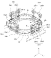
도 12는 제2 코일(230), 회로 기판(250) 및 베이스(210)의 부분 결합 사시도를 나타내고, 도 13은 제2 코일(230), 회로 기판(250) 및 베이스(210)의 분해 사시도를 나타낸다.12 is a partial perspective view of the
먼저, 제2 렌즈 구동 유닛(200)의 베이스(210)는 도 2에 예시된 바와 같이, 대략 사각 평면 형상을 가질 수 있으며, 직선면에 복수의 지지 부재 쌍(220)이 고정될 수 있다. 베이스(210)에는 커버 부재(300)를 접착 고정할 때, 접착제가 도포될 수 있도록 도 12 및 도 13에 예시된 바와 같이 단턱(211)이 형성될 수 있다. 이때, 단턱(211)의 바닥면은 커버 부재(300)의 단부와 면 접촉될 수 있다.First, the
베이스(210)는 제1 렌즈 구동 유닛(100)과 일정 간격 이격되어 배치될 수 있다. 베이스(210)에서 회로 기판(250)의 단자(251)가 형성된 부분과 마주보는 면에는 대응되는 크기의 지지홈이 형성될 수 있다. 이 지지홈은 베이스(210)의 외주면으로부터 일정 깊이 안쪽으로 오목하게 형성되어, 단자(251)가 형성된 단자면(253)이 외측으로 돌출되지 않도록 하거나 돌출되는 양을 조절할 수 있다.The base 210 may be spaced apart from the first
단턱(211)은 상측에 결합되는 커버 부재(300)를 가이드할 수 있으며, 또한, 커버 부재(300)의 단부가 면 접촉하도록 결합될 수 있다. 단턱(211)과 커버 부재(300)의 단부는 접착제 등에 의해 접착 고정 및 실링 될 수 있다.The
베이스(210)의 상부면에는 모서리 부분에 복수의 지지 부재 쌍(220)이 삽입될 수 있는 지지 부재 안착홈(214)이 오목하게 형성될 수 있다. 지지 부재 안착홈(214)에는 접착제가 도포되어 복수의 지지 부재 쌍(220)이 움직이지 않도록 고정할 수 있다. 지지 부재 안착홈(214)에 복수의 지지 부재 쌍(220)의 끝단이 삽입 또는 배치되어 접착제 등을 통해 고정될 수 있다. 지지 부재 안착홈(214)은 복수의 지지 부재 쌍(220)이 설치되는 직선 면에 각각 복수 개 또는 적어도 하나 이상이 형성될 수 있는데, 이 지지 부재 안착홈(214)의 형상은 대략 사각 형상의 홈으로 마련될 수 있다. A support
또한, 지지 부재 안착홈(214)은 도 13에 도시된 바와 같이 실시 예에서는 직선 면마다 2개씩 마련될 수 있는데, 이는 복수의 지지 부재 쌍(220)의 형상에 따라 증감될 수 있으며, 1개가 형성될 수도 있으며, 3개 이상이 형성될 수도 있다. 실시 예에서는, 복수의 지지 부재 쌍(220)의 제1 및 제2 지지 부재 각각의 끝단이 지지 부재 안착홈(214)에 삽입 또는 배치될 수 있도록 직선 면마다 2개씩 지지 부재 안착홈(214)이 형성되어 있다.13, two supporting
또한, 베이스(210)의 상부면에는 제2 감지 센서(240)가 배치될 수 있는 제2 감지 센서 안착홈(215)이 마련될 수 있다. 실시 예에 따르면, 제2 감지 센서 안착홈(215)은 총 2개가 마련되어 있어, 제2 감지 센서(240)가 제2 감지 센서 안착홈(215)에 배치되어 하우징(140)이 상기한 제2 방향과 제3 방향으로 움직이는 정도를 감지할 수 있다. 이를 위해 제2 감지 센서 안착홈(215)과 베이스(210)의 중심을 연결하는 가상의 선들이 이루는 각도는 90도가 되도록 2개의 제2 감지 센서 안착홈(215)을 배치할 수 있다.In addition, a second sensing
제2 감지 센서 안착홈(215)의 적어도 한 면에는 테이퍼진 경사면(미도시)을 형성할 수도 있다. 제2 감지 센서(240)의 조립을 위한 에폭시 주입 등이 보다 원활하게 이루어질 수 있도록 구성할 수 있다. 또한, 제2 감지 센서 안착홈(215)에 별도의 에폭시 등이 주입되지 않을 수도 있으나, 에폭시 등을 주입하여 제2 감지 센서(240)를 고정시킬 수도 있다. 제2 감지 센서 안착홈(215)의 위치는 제2 코일(230)의 중앙 또는 중앙부근에 배치될 수 있다. 또는, 제2 코일(230)의 중심과 제2 감지 센서(240)의 중심을 일치시킬 수도 있다. 실시 예에 따르면 제2 감지 센서 안착홈(215)은 베이스(210)의 모서리 부분에 설치되는 것이 좋다. 이는 복수의 지지 부재 쌍(220)과의 간섭을 최소화하기 위함이다.A tapered inclined surface (not shown) may be formed on at least one surface of the second
제2 감지 센서(240)는 회로 기판(250)을 사이에 두고 제2 코일(230)의 중심 측에 배치될 수 있다. 즉, 제2 감지 센서(240)는 제2 코일(230)과 직접 연결되는 것이 아니며, 회로 기판(250)을 기준으로 상부면에는 제2 코일(230)이, 하부면에는 제2 감지 센서(240)가 설치될 수 있다. 실시 예에 따르면, 제2 감지 센서(240)와 제2 코일(230) 및 제1 마그네트(130)는 서로 동일 축에 배치될 수 있다.The
이와 같은 구성에 따라, 제2 코일(230)은 제1 마그네트(130)와의 상호 작용을 통해, 제2 및/또는 제 3 방향으로 하우징(140)을 움직여, 손떨림 보정을 수행할 수 있도록 한다.According to this configuration, the
커버 부재(300)의 단턱(211)과 대응되는 위치에는 홈부가 형성되어, 이 홈부를 통해 접착제 등이 주입될 수 있다. 이때, 주입되는 접착제는 점성이 낮게 설정되어, 홈부를 통해 주입된 접착제가 단턱(211)과 커버 부재(300)의 단부의 면 접촉 위치에 스며들 수 있다. 이와 같이 홈부에 도포된 접착 부재는 홈부를 통해 커버 부재(300)와 베이스(210)의 서로 마주보는 면들 사이의 갭(gap)을 메우어, 커버 부재(300)가 베이스(210)와 결합되면서 실링 할 수 있도록 구성될 수 있다.A groove portion is formed at a position corresponding to the
또한, 베이스(210)의 하면에는 필터가 설치되는 안착부(미도시)가 형성될 수도 있다. 이러한 필터는 적외선 차단 필터일 수 있다. 그러나 이를 한정하는 것은 아니며, 베이스(210) 하부에 별도 센서 홀더에 필터가 배치될 수도 있다. 또한, 후술하겠지만, 베이스(210)의 하면에는 이미지 센서가 실장된 센서 기판이 결합되어 카메라 모듈을 구성할 수도 있다.In addition, a seating part (not shown) on which a filter is installed may be formed on a lower surface of the
복수의 지지 부재 쌍(220)은 하우징(140)의 복수의 측면에 각각 배치될 수 있다. 실시 예에서, 복수의 지지 부재 쌍(220) 각각은 2개의 제1 및 제2 지지 부재를 포함하는 것으로 설명하지만, 지지 부재 쌍(220) 각각은 3개 이상의 지지 부재를 포함할 수도 있다.A plurality of pairs of
예를 들어, 전술한 바와 같이, 하우징(140)이 다각형 평면 형상을 가질 경우, 하우징(140)의 측면의 개수는 복수 개이다. 만일, 하우징(140)이 도 6 및 도 7에 예시된 바와 같이 팔각 평면 형상을 가질 경우, 복수의 지지 부재 쌍(220)은 팔각 측면 중 해당하는 측면에 배치될 수 있다. 또는, 하우징(140)이 4각 평면 형상을 가질 경우, 복수의 지지 부재 쌍(220)은 4개의 측면에 각각 배치될 수도 있다.For example, as described above, when the
이하, 복수의 지지 부재 쌍(220)의 개수가 도 2, 도 3, 및 도 8에 예시된 바와 같이 4개인 것으로 가정하여 설명하지만, 지지 부재 쌍(220)의 개수는 3개일 수도 있다. 즉, 하우징(140)의 4개의 제2 면(142)에 제1 내지 제4 지지 부재 쌍(220-1, 220-2, 220-3, 220-4)이 각각 배치된 것으로 설명한다.Hereinafter, it is assumed that the number of the plurality of support member pairs 220 is four as illustrated in Figs. 2, 3, and 8, but the number of the support member pairs 220 may be three. That is, the first to fourth support member pairs 220-1, 220-2, 220-3, and 220-4 are disposed on the four
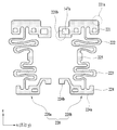
도 14는 실시 예에 의한 복수의 지지 부재 쌍(220) 각각의 정면도를 나타낸다.14 shows a front view of each of a plurality of pairs of
제1 내지 제4 지지 부재 쌍(220:220-1, 220-2, 220-3, 220-4)은 하우징(140)의 8개의 측면 중에서, 4개의 제2 면(142)에 개별적으로 배치되어 하우징(140)을 베이스(210)에 대하여 일정거리 이격시켜 지지할 수 있다. 실시 예에 따른 제1 내지 제4 지지 부재 쌍(220:220-1, 220-2, 220-3, 220-4) 각각은 하우징의 제2 면(142)에 각각 배치되므로, 총 4개의 지지 부재 쌍이 상호 대칭으로 설치될 수 있다. 그러나 이를 한정하는 것은 아니며, 각 직선면 마다 2개씩 8개의 쌍으로 구성될 수도 있다.The first to fourth support member pairs 220: 220-1, 220-2, 220-3, and 220-4 are individually disposed on the four
제1 내지 제4 지지 부재 쌍(220:220-1, 220-2, 220-3, 220-4) 각각은 서로 분할된 제1 및 제2 지지 부재(220a, 220b)를 포함할 수 있다. 즉, 제1 지지 부재 쌍(220-1)은 제1 지지 부재(220a-1) 및 제2 지지 부재(220b-1)를 포함하고, 제2 지지 부재 쌍(220-2)은 제1 지지 부재(220a-2) 및 제2 지지 부재(220b-2)를 포함하고, 제3 지지 부재 쌍(220-3)은 제1 지지 부재(220a-3) 및 제2 지지 부재(220b-3)를 포함하고, 제4 지지 부재 쌍(220-4)은 제1 지지 부재(220a-4) 및 제2 지지 부재(220b-4)를 포함할 수 있다. 여기서, 제1 지지 부재와 제2 지지 부재는 하우징(140)의 동일 측면에서 인접하여 설치될 수 있다.Each of the first to fourth support member pairs 220: 220-1, 220-2, 220-3, and 220-4 may include first and
제1 지지 부재(220a-1, 220a-2, 220a-3, 220a-4) 및 제2 지지 부재(220b-1, 220b-2, 220b-3, 220b-4) 각각은 상측 단자부(221), 적어도 하나의 탄성 변형부(222, 223, 225) 및 하측 단자부(224)를 포함할 수 있다. 또한, 도 14에 예시된 제1 및 제2 지지 부재는 제1 방향인 z축 방향에 수직한 방향(예, x축 또는 y축 방향으로 서로 대칭인 형상을 가질 수 있다. 만일, 도 14에 예시된 지지 부재 쌍(220)이 도 3 및 도 8에 예시된 제1 또는 제4 지지 부재 쌍(220-1, 220-4)에 해당할 경우, 제1 및 제2 지지 부재는 z축 방향에 수직인 y축 방향으로 대칭일 수 있다. 또한, 도 14에 예시된 지지 부재 쌍(220)이 제2 또는 제3 지지 부재 쌍(220-2, 220-3)에 해당할 경우, 제1 및 제2 지지 부재는 z축 방향에 수직인 x축 방향으로 대칭일 수 있다.Each of the first supporting
도 6 및 도 7에 예시된 하우징(140)의 도피 홈(142a)의 바닥면은 오픈된 개구를 형성하도록 하여, 지지 부재 쌍(220)의 하측 단자부(224)가 하우징(140)과 간섭되는 것을 방지할 수 있다. 또한, 도피 홈(142a)의 상측은 도 7에 예시된 바와 같이 단차부(142b)를 구성하여 지지 부재 쌍(220)의 상측 단자부(221)의 안쪽을 지지할 수 있다.The bottom surface of the
도 3 및 도 14를 참조하면, 상측 단자부(221)는 하우징(140)의 제2 면(142)의 상단부와 결합되는 곳으로서, 제2 면(142)에 돌출 형성된 결합 돌기(147)와 대응되는 위치에 오목 홈부(147a)를 형성하여 이들의 끼워 맞춤으로 고정될 수 있다. 상측 단자부(221)는 상측 탄성 부재(150)와 전기적으로 연결될 수 있는 부분이다.3 and 14, the
실시 예에 의하면, 도 9에 예시된 제1 및 제2 상측 탄성 부재(150a, 150b)의 제1 및 제2 지지 부재 접촉부(150a-1, 150b-1)는 제1 지지 부재 쌍(220-1)의 제1 및 제2 지지 부재(220a-1, 220b-1)의 상측 단자부(221)와 각각 전기적으로 연결될 수 있도록 대향하여 배치될 수 있다. 여기서, 제1 지지 부재 쌍이란, 제1 내지 제4 지지 부재 쌍(220-1, 220-2, 220-3, 2204) 중에서 제1 코일(120)에 전원을 공급하도록 역할이 할당된 지지 부재 쌍을 의미한다. 따라서, 제1 및 제2 지지 부재(220a-1, 220b-1)가 하우징(140)의 동일 측면에서 인접하여 배치된 것처럼, 제1 및 제2 상측 탄성 부재(150a, 150b)의 제1 및 제2 지지 부재 접촉부(150a-1, 150b-1)도 서로 이웃하여 배치될 수 있다.According to the embodiment, the first and second
도 3을 참조하면, 제1 지지 부재 쌍(220-1)에서 제1 지지 부재(220a-1)의 상측 단자부(221)와 제1 지지 부재 접촉부(150a-1)가 제1 접점(CP1)에서 솔더링 등을 통해 서로 전기적으로 연결될 수 있다. 제1 지지 부재 쌍(220-1)에서 제2 지지 부재(220b-1)의 상측 단자부(221)와 제2 지지 부재 접촉부(150b-1)가 제2 접점(CP2)에서 솔더링 등을 통해 서로 전기적으로 연결될 수 있다. 즉, 제1 지지 부재 쌍(220-1)에서, 제1 지지 부재(220a-1)의 상측 단자부(221)는 제1 상측 탄성 부재(150a)와 전기적으로 연결되고, 제2 지지 부재(220b-1)의 상측 단자부(221)는 제2 상측 탄성 부재(150b)와 전기적으로 연결될 수 있다. 이와 같은 구성에 의해, 2개로 분할된 제1 및 제2 상측 탄성 부재(150a, 150b)는 제1 지지 부재 쌍(220-1)의 제1 및 제2 지지 부재(220a-1, 220b-1)와 각각 전기적으로 연결되어 회로 기판(250)으로부터 받은 전원(또는, 전류)를 제1 코일(120)에 인가할 수 있다.3, the
또한, 도 14에 예시된 제1 및 제2 지지 부재의 상측 단자부(221)는 제1 및 제2 상측 탄성 부재(150a, 150b)에 전원 공급을 위한 제1 접촉 단자부(221a)를 포함할 수 있다. 여기서, 제1 접촉 단자부(221a)는 상측 단자부(221)의 상부 가장 자리에 배치될 수 있다. 그러나, 제1 접촉 단자부(221a)는 상측 단자부(221)와 별도로 마련될 수도 있다. 제1 및 제2 지지 부재 각각의 제1 접촉 단자부(221a)는 양(+)극 또는 음(-)극 전원을 인가받을 수 있다.The upper
또한, 제1 및 제2 지지 부재의 상측 단자부(221)는 제1 감지 센서(170)와 회로 기판(250)을 연결하기 위한 제2 접촉 단자부(221b)를 더 포함할 수 있다. 여기서, 제2 접촉 단자부(221b)는 상측 단자부(221)의 하부 가장 자리에 배치될 수 있다. 그러나, 제2 접촉 단자부(221a)는 상측 단자부(221)와 별도로 마련될 수도 있다.The
적어도 하나의 탄성 변형부(222, 223, 225)는 상측 단자부(221)로부터 길이 방향으로 연장되어 적어도 1회 이상 구부러진 형상으로 마련되어, 일정 형태의 패턴을 형성할 수 있다. 여기서, 길이 방향이란, 상측 단자부(221)와 하측 단자부(224)를 서로 연결하는 방향일 수 있다.The at least one
실시 예에 따르면, 적어도 하나의 탄성 변형부는 제1 및/또는 제2 탄성 변형부(222, 223)를 포함할 수 있다.According to an embodiment, the at least one resiliently deformable portion may include the first and / or second resiliently
제1 탄성 변형부(222)가 2번 이상의 절곡을 통해 지그재그 형상으로 마련될 경우, 제2 탄성 변형부(223) 또한 이와 대응되게 형성될 수 있으나, 이에 한정되지 않는다. 다른 실시 예에 의하면, 제2 탄성 변형부(223)는 생략되거나 제1 탄성 변형부(222)와 다른 형상으로 마련될 수도 있다. 도 14는 일 실시 예일 뿐이며, 그 외에도 지그재그 형상 등 다양한 패턴을 가지도록 구성하는 것도 가능하다. 이때, 제1 및 제2 탄성 변형부(222, 223)를 구분하지 않고 하나로만 구성할 수도 있고, 이러한 패턴 없이 서스펜션 와이어의 형태로만 구성하는 것도 가능하다. 실시 예에 따르면 제1 및 제2 탄성 변형부(222, 223)의 직선 부분은 광축에 수직한 평면과 대략 평행하도록 형성될 수 있다.When the first
제1 및 제2 탄성 변형부(222, 223)는 하우징(140)이 광축에 수직한 평면인 제2 및/또는 제 3 방향으로 움직일 때, 하우징(140)이 움직이는 방향 또는 지지 부재 쌍의 길이 방향으로 미세하게 탄성 변형될 수 있다. 그러면, 하우징(140)은 광축과 평행한 방향인 제1 방향에 대해서는 거의 위치 변화없이 실질적으로 광축과 수직한 평면인 제2 및 제3 방향으로 움직일 수 있어 손떨림 보정의 정확도를 높일 수 있다. 이는 탄성 변형부(222, 223)가 길이방 향으로 늘어날 수 있는 특성을 활용한 것이다.The first and second elastically
또한, 적어도 하나의 탄성 변형부는 연결부(225)를 더 포함할 수 있다. 연결부(225)는 제1 및 제2 탄성 변형부(222, 223)의 중간에 배치될 수 있으나 이에 한정되는 것은 아니며, 하나의 탄성 변형부와 연결되어 배치될 수도 있다. 제1 및 제2 탄성 변형부(222, 223)는 연결부(225)를 가운데에 개재한 상태로 형성될 수도 있으며, 또한 상호 대응되는 형상으로 마련될 수도 있다.In addition, the at least one elastic deformation portion may further include a
연결부(225)는 댐핑 역할을 수행할 수 있도록 플레이트 형상으로 마련될 수 있으며, 연결부(225)에 복수 개의 홀(미도시) 또는 홈(미도시)이 형성되어 홀 또는 홈을 통해 연결부(225)와 하우징(140)을 UV댐퍼 등을 이용하여 댐핑부를 구성할 수도 있다.A plurality of holes (not shown) or grooves (not shown) may be formed in the
실시 예의 경우, 제1 및 제2 탄성 변형부(222, 223)는 상측 단자부(221)와 하측 단자부(224) 사이에 배치된 것으로 도시되어 있지만, 실시 예는 이에 국한되지 않는다. 다른 실시 예에 의하면, 도 14에 예시된 바와 달리, 제1 및 제2 지지 부재 각각의 양끝단에 하나 이상의 탄성 변형부를 포함할 수도 있다.In the embodiment, the first and second
하측 단자부(224)는 도 14에 예시된 제1 및 제2 지지 부재 각각의 단부에 마련되며, 적어도 하나의 탄성 변형부(222 ,223, 225)로부터 연장되어 베이스(210)와 결합될 수 있다. 하측 단자부(224)의 일 끝단(224a)은 베이스(210)에 형성된 지지 부재 안착홈(214)에 삽입 또는 배치되어 에폭시 등과 같은 접착 부재에 의해 고정 결합될 수 있다. 그러나 이를 한정하는 것은 아니며, 지지 부재 안착홈(214)을 하측 단자부(224)와 대응되도록 하여 이들을 끼워 맞춤 결합할 수도 있다. 또는, 하측 단자부(224)의 일 끝단(224a)은 2개 이상의 형상으로 분기되어 형성될 수도 있으며, 이에 대응되게 베이스(210)에는 하나의 지지 부재 당 2개 이상의 지지 부재 안착홈(214)이 형성될 수도 있다.The lower
또한, 하측 단자부(224)의 타 끝단(224b)은 회로 기판(250)의 패드부(252-1, 252-2, 252-3, 252-4)의 각 패드 상단에 안착되어 연결될 수 있다.The
하측 단자부(224)는 제1 및 제2 탄성 변형부(222, 223)의 폭 보다 넓은 플레이트 형상으로 마련될 수 있으나 이에 한정되지 않고, 좁거나 대응되는 폭을 가질 수도 있다.The lower
한편, 제2 코일(230)은 하우징(140)에 고정되는 제1 마그네트(130)와 대향 하도록 배치될 수 있다. 일 예로, 제2 코일(230)은 제1 마그네트(130)의 외측에 배치될 수 있다. 또는, 제2 코일(230)은 제1 마그네트(130)의 하측에 일정 거리 이격되어 설치될 수 있다.Meanwhile, the
실시 예에 따르면, 도 12 및 도 13에 예시된 바와 같이 제2 코일(230)은 회로 기판(250)의 네 모서리 부분에 총 4개 설치될 수 있으나, 이를 한정하는 것은 아니며, 제2 방향용 1개, 제3 방향용 1개 등 2개만이 설치되는 것도 가능하고, 4개 이상 설치될 수도 있다. 실시 예의 경우 회로 기판(250)에 제2 코일(230) 형상으로 회로 패턴을 형성하고, 추가적으로 별도의 제2 코일(230)이 회로 기판(250) 상부에 배치될 수도 있으나, 이에 한정되지 않으며, 회로 기판(250)에 제2 코일(230) 형상으로 회로패턴을 형성하지 않고 회로 기판(250) 상부에 별도의 제2 코일(230)만이 배치될 수도 있다. 또는, 도넛 형상으로 와이어를 권선하여 제2 코일(230)을 구성하거나 또는 FP코일형태로 제2 코일(230)을 형성하여 회로 기판(250)에 전기적으로 연결하여 구성하는 것도 가능하다.According to the embodiment, as illustrated in FIGS. 12 and 13, a total of four
제2 코일(230)을 포함한 회로부재(231)는 베이스(210)의 상측에 배치되는 회로 기판(250)의 상부면에 설치될 수 있다. 그러나 이를 한정하는 것은 아니며, 제2 코일(230)은 베이스(210)와 밀착 배치될 수도 있고, 일정 거리 이격 배치될 수도 있으며, 별도 기판에 형성되어 이 기판을 회로 기판(250)에 적층 연결할 수도 있다.The
전술한 바와 같이 구현된 제1 마그네트(130)와 제2 코일(230)의 상호 작용에 의해 하우징(140)이 제2 및 제3 방향으로 이동될 수 있다. 이를 위해, 전술한 제1 내지 제4 지지 부재 쌍(220-1, 220-2, 220-3, 220-4)은 하우징(140)을 베이스(210)에 대하여 제1 방향에 직교하는 제2 및 제3 방향으로 이동 가능하게 지지할 수 있다.The
한편, 제2 감지 센서(240)는 제2 코일(230)의 중심에 배치되어, 하우징(140)의 움직임을 감지할 수 있다. 제2 감지 센서(240)는 홀 센서로 마련될 수 있으며, 자기력 변화를 감지할 수 있는 센서라면 어떠한 것이든 사용 가능하다. 제2 감지 센서(240)는 도 13에 도시된 바와 같이, 회로 기판(250)의 하측에 배치되는 베이스(210)의 모서리 부분에 총 2개가 설치될 수 있으며, 실장 된 제2 감지 센서(240)는 베이스(210)에 형성된 제2 감지 센서 안착홈(215)에 삽입 배치될 수 있다. 회로 기판(240)의 하면은 제2 코일(230)이 배치된 면의 반대면 일 수 있다.Meanwhile, the
도 15는 실시 예에 의한 회로 기판(250)의 사시도를 나타낸다.15 shows a perspective view of the
도 13 및 도 15를 참조하면, 회로 기판(250)은 복수의 패드부(252-1, 252-2, 252-3, 252-4)를 포함할 수 있다. 복수의 패드부(252-1, 252-2, 252-3, 252-4)는 복수의 지지 부재 쌍(220-1, 220-2, 220-3, 220-4) 각각의 하측 단자부(224)의 타끝단(224b)과 연결 가능한 형태를 가질 수 있다. 즉, 제1 지지 부재 쌍(220-1)의 제1 및 제2 지지 부재(220a-1, 220b-1)의 하측 단자부(224)의 타 끝단(224b)은 제1 패드부(252-1)의 패드들과 각각 연결되고, 제2 지지 부재 쌍(220-2)의 제1 및 제2 지지 부재(220a-2, 220b-2)의 하측 단자부(224)의 타 끝단(224b)은 제2 패드부(252-2)의 패드들과 각각 연결되고, 제3 지지 부재 쌍(220-3)의 제1 및 제2 지지 부재(220a-3, 220b-3)의 하측 단자부(224)의 타 끝단(224b)은 제3 패드부(252-3)의 패드들과 각각 연결되고, 제4 지지 부재 쌍(220-4)의 제1 및 제2 지지 부재(220a-4, 220b-4)의 하측 단자부(224)의 타 끝단(224b)은 제4 패드부(252-4)의 패드들과 각각 연결될 수 있다. 제1 내지 제4 패드부(252-1, 252-2, 252-3, 252-4) 각각에는 2개의 패드가 있어 해당하는 지지 부재 쌍의 제1 및 제2 지지 부재와 각각 연결될 수 있다.13 and 15, the
회로 기판(250)은 전술한 패드부(252-1, 252-2, 252-3, 252-4)와 전기적으로 연결된 복수의 단자(251)를 더 포함할 수 있다.The
회로 기판(250)은 베이스(210)의 상부면에 결합되며, 지지 부재 안착홈(214)이 노출될 수 있도록 대응되는 위치에 제5 통공(255)이 형성될 수 있다. 회로 기판(250)에는 절곡된 단자면(233)이 형성될 수 있다. 실시 예에 의하면, 회로 기판(250)의 1개의 절곡된 단자면(253)에는 적어도 하나의 단자(251)가 설치될 수 있다. The
실시 예에 의하면, 단자면(253)에 설치된 복수 개의 단자(251)를 통해 외부 전원을 인가받아 제1 및 제2 코일(120, 230) 및 제1 감지 센서(170)에 전원을 공급할 수도 있고, 제1 감지 센서(170)로부터의 신호를 보빈(110)의 위치를 제어하기 위해 필요한 궤환 신호로서 외부로 출력할 수도 있다.The power may be supplied to the first and
단자(251)가 설치되는 단자면(253)에 형성된 단자들의 개수는 제어가 필요한 구성 요소들의 종류에 따라 증감될 수 있다.The number of terminals formed on the
실시 예에 따르면, 회로 기판(250)은 FPCB로 마련될 수 있으나 이를 한정하는 것은 아니며, 회로 기판(250)의 단자 구성 등을 베이스(210)의 표면에 표면 전극 방식 등을 이용하여 직접 형성하는 것도 가능하다.According to the embodiment, the
이하, 전술한 구성을 갖는 렌즈 구동 장치에서, 복수의 지지 부재 쌍(220)을 이용하여, 제1 감지 센서(170)에 전원을 공급하고 제1 감지 센서(170)로부터 출력되는 센싱 신호를 회로 기판(250)에 전달하는 과정에 대해 첨부된 도면을 참조하여 예시적으로 다음과 같이 설명한다.Hereinafter, in the lens driving apparatus having the above-described configuration, a plurality of support member pairs 220 are used to supply power to the
제1 감지 센서(170)가 홀 센서로 구현될 경우, 홀 센서(170)는 복수의 핀들을 가질 수 있다. 예를 들어, 복수의 핀은 제1 및 제2 핀을 포함할 수 있다. 제1 핀은 전압과 접지에 각각 연결되는 제1-1 및 제1-2 핀을 포함할 수 있고, 제2 핀은 센싱된 결과를 출력하는 제2-1 및 제2-2 핀을 포함할 수 있다. 여기서, 제2-1 및 제2-2 핀을 통해 출력되는 센싱된 결과는 전류 형태일 수 있으나, 실시 예는 신호의 형태에 국한되지 않는다.When the
실시 예에 의하면, 제2 지지 기판 쌍(220-2)을 이용하여 회로 기판(250)으로부터 제1 감지 센서(170)의 제1-1 및 제1-2 핀으로 전원을 공급할 수 있고, 제3 지지 기판 쌍(220-3)을 이용하여 제1 감지 센서(170)의 제2-1 및 제2-2 핀으로부터 회로 기판(250)으로 센싱된 결과를 전달할 수도 있다. 여기서, 제2 지지 기판 쌍이란, 제1 내지 제4 지지 기판 쌍(220-1, 220-2, 220-3, 220-4) 중에서 제1 지지 기판 쌍(220-1)을 제외한 임의의 지지 기판 쌍을 의미한다. 또한, 제3 지지 기판 쌍이란, 제1 내지 제4 지지 기판 쌍(220-1, 220-2, 220-3, 220-4) 중에서, 제1 및 제2 지지 기판 쌍을 제외한 임의의 지지 기판 쌍을 의미한다.According to the embodiment, the second support substrate pair 220-2 can be used to supply power from the
도 16은 도 3에 예시된 렌즈 구동 장치에서 하측 탄성 부재(160), 제1 내지 제4 지지 부재 쌍(220-1, 220-2, 220-3, 220-4) 및 회로 기판(250)만의 사시도를 나타낸다.16 is a plan view of the lower
제1 감지 센서(170)의 제1-1 및 제1-2 핀은 제2 지지 부재 쌍(220-2)을 통해 회로 기판(250)과 연결될 수 있다. The 1-1 and 1-2 pins of the
이를 위해, 도 14에 예시된 제1 및 제2 지지 부재 각각의 상측 단자부(221)의 제2 접촉 단자부(221b)를 이용할 수 있다. 그러나, 실시 예는 이에 국한되지 않으며, 상측 단자부(221)는 제2 접촉 단자부(221b)와 다른 형태로 제1-1 및 제1-2 핀과 연결될 수 있다. To this end, the second contact terminal portion 221b of the
부연하면, 도 3에 예시된 바와 같이, 제2 지지 부재 쌍(220-2)의 제1 지지 기판(220a-2)의 상측 단자부(221)의 제2 접촉 단자부(221b)는 제1-1 핀과 제3 접점(CP3)에서 전기적으로 연결되고, 제2 지지 부재 쌍(220-2)의 제2 지지 부재(220b-2)의 상측 단자부(221)의 제2 접촉 단자부(221b)는 제1-2 핀과 제4 접점(CP4)에서 전기적으로 연결될 수 있다. 또한, 제2 지지 부재 쌍(220-2)의 제1 및 제2 지지 기판(220a-2, 220b-2)의 하측 단자부(224)는 회로 기판(250)의 제2 패드부(252-2)의 패드들과 제7 및 제8 접점(CP7, CP8)에서 각각 연결될 수 있다.3, the second contact terminal portion 221b of the
전술한 연결에 의해, 제1 감지 센서(170)의 제1-1 및 제1-2 핀은 제2 지지 부재 쌍(220-2)의 제1 및 제2 지지 기판(220a-2, 220b-2)을 통해 회로 기판(250)과 연결될 수 있음을 알 수 있다. 도 16을 참조하면, 제1 감지 센서(170)의 제1-1 및 제1-2 핀으로부터 회로 기판(250)의 제2 패드부(252-2)까지의 통전 경로가 P1 및 P2로 각각 도시되어 있다.The 1-1 and 1-2 pins of the
또한, 제1 감지 센서(170)의 제2-1 및 제2-2 핀은 제1 및 제2 하측 탄성 부재(160a, 160b)를 경유하여 제3 지지 부재 쌍(220-3)을 통해 회로 기판(250)과 연결될 수 있다.Further, the second-1 and second-2 pins of the
이를 위해, 도 3을 참조하면, 제2-1 핀은 제5 접점(CP5)에서 제1 하측 탄성 부재(160a)의 일측인 제1-1 센서 접촉부(160a-1)의 끝단과 전기적으로 연결되고, 제2-2 핀은 제6 접점(CP6)에서 제2 하측 탄성 부재(160b)의 일측인 제2 센서 접촉부(160b-1)의 끝단과 전기적으로 연결될 수 있다.3, the 2-1 pin is electrically connected to the end of the 1-1
또한, 도 3, 도 8 및 도 16을 참조하면, 제1 하측 탄성 부재(160a)의 일측인 제1-1 센서 접촉부(160a-1)는 외측 프레임(162)과 제1 하측 탄성 부재(160a)의 타측인 제1-2 센서 접촉부(160a-2)를 통해 제3 지지 부재 쌍(220-3)의 제1 지지 부재(220a-3)의 제2 접촉 단자부(221b)와 제9 접점(CP9)에서 연결될 수 있다. 또한, 제2 하측 탄성 부재(160b)의 일측인 제2-1 센서 접촉부(160b-1)는 외측 프레임(162)과 제2 하측 탄성 부재(160b)의 타측인 제2-2 접촉 단자부(160b-2)를 통해 제3 지지 부재 쌍(220-3)의 제2 지지 부재(220b-3)의 제2 접촉 단자부(221b)와 제10 접점(CP10)에서 연결될 수 있다.3, 8, and 16, the first
제3 지지 부재 쌍(220-3)의 제1 및 제2 지지 부재(220a-3, 220b-3)의 제2 접촉 단자부(221b)로부터 연장된 하측 단자부(224)는 회로 기판(250)의 제3 패드부(252-3)의 패드들과 연결되어 있다. 따라서, 제1 감지 센서(170)의 제2-1 및 제2-2 핀은 하부 탄성 부재(160)를 경유하여 제3 지지 부재 쌍(220-3)을 통해 회로 기판(250)과 연결될 수 있음을 알 수 있다. 도 16을 참조하면, 제1 감지 센서(170)의 제2-1 및 제2-2 핀으로부터 회로 기판(250)의 제3 패드부(252-3)까지의 통전 경로가 P3 및 P4로 각각 도시되어 있다.The lower
실시 예에 의하면, 제1 감지 센서(170)의 제1-1 및 제1-2 핀을 회로 기판(250)에 연결시키는 제2 지지 부재 쌍(220-2)과 제2-1 및 제2-2 핀을 회로 기판(250)에 연결시키는 제3 지지 부재 쌍(220-3)은 서로 y축 방향으로 대칭일 수 있다. 이를 위해, 제2 지지 부재 쌍(220-2)과 제3 지지 부재 쌍(220-3)은 하우징(140)의 서로 대향하는 측면에 각각 배치될 수 있다.According to the embodiment, the second support member pair 220-2 connecting the 1-1 and 1-2 pin of the
만일, 렌즈 구동 장치에서 지지 기판의 개수가 총 4개이고, 이들 중 2개의 지지 기판을 이용하여 제1 코일(120)로 전원을 공급할 경우, 회로 기판(250)에서 필요한 패드의 개수는 2개에 불과하다. 그러나, 실시 예에 의하면, 지지 기판의 개수가 총 8개이고, 이들 중에서 2개의 지지 기판은 제1 코일(120)에 전원을 공급하는 데 사용되고, 나머지 6개의 지지 기판 중에서 4개의 지지 기판은 제1 감지 센서(170)의 4개의 핀들과 회로 기판(250)을 연결하는 데 사용되므로 회로 기판(250)에서 필요한 패드의 개수는 6개일 수 있다. 이와 같이, 실시 예에 의하면, 지지 기판의 개수가 증가하였으므로, 회로 기판(250)에서 필요한 패드의 개수도 증가할 수 있으며, 단자(251)의 개수도 증가할 수 있다.If the number of the supporting substrates is four in the lens driving apparatus and the power is supplied to the
만일, 지지 기판의 개수가 4개일 경우에 회로 기판(250)에서 단자(251)의 개수가 14개이라면, 실시 예에 의한 회로 기판(250)에서 단자(251)의 개수는 18개 내지 20개가 될 수 있으나, 실시 예는 단자(251)의 개수에 국한되지 않는다.If the number of the
실시 예에 의한 렌즈 구동 장치에서 제1 내지 제4 지지 부재 쌍(220-1, 220-2, 220-3, 220-4) 각각은 서로 전기적으로 분할된 제1 및 제2 지지 부재를 포함할 수 있다. 이때, 제1 지지 부재 쌍(220-1)을 이용하여 제1 코일(120)에 전원을 공급할 수 있으며, 제1 지지 부재 쌍(220-1)의 제1 및 제2 지지 부재(220a-1, 220b-1)의 상측 단자부(221)는 하우징(140)의 동일한 측면에서 서로 인접하여 배치된다. 그리고, 제1 지지 부재(220a-1)의 상측 단자부(221)는 제1 상부 탄성 부재(150a)의 제1 지지 부재 접촉부(150a-1)와 대향하도록 배치되고, 제2 지지 부재(220b-1)의 상측 단자부(221)는 제2 상부 탄성 부재(150b)의 제2 지지 부재 접촉부(150b-1)와 대향하도록 배치된다. 따라서, 제1 지지 부재 쌍(220-1)과 상부 접촉 부재(150)는 하우징(140)의 일측면에서 솔더링에 의해 전기적으로 서로 연결될 수 있어, 제1 및 제2 지지 부재 접촉부(150a-1, 150b-1)가 보빈(110)을 중심으로 서로 180°대향하여 대칭적으로 위치할 때보다 훨씬 제조 공정이 단순해질 수 있다.In the lens driving apparatus according to the embodiment, each of the first to fourth support member pairs 220-1, 220-2, 220-3, and 220-4 includes first and second support members electrically separated from each other . At this time, power can be supplied to the
또한, 보빈(110)의 위치를 정확하게 제어하기 위해서, 렌즈 구동 장치가 제1 감지 센서(170)를 추가적으로 포함할 경우, 추가된 제1 감지 센서(170)를 위한 별도의 부재를 요구하지 않는다. 왜냐하면, 제1 감지 센서(170)는 통상 4개의 핀을 갖는데, 별도의 부재나 선로를 이용하지 않고 손떨림 보정을 위해 이용되는 지지 부재 쌍(220) 및 하부 탄성 부재(160)를 이용하여 4개의 핀과 회로 기판(250)을 연결할 수 있기 때문이다. 따라서, 실시 예에 의한 렌즈 구동 장치의 제작 비용이 저렴하고 구조가 간단해 질 수 있다. 이는 제1 감지 센서(170) 이외에 렌즈 구동 장치의 동작을 돕기 위한 다른 디바이스를 추가적으로 배치할 경우에도 마찬가지로 적용될 수 있다.Further, in order to precisely control the position of the
한편, 전술한 실시 예에 의한 렌즈 구동 장치는 다양한 분야 예를 들어 카메라 모듈에 이용될 수 있다. 예를 들어, 카메라 모듈은 휴대폰 등 모바일 기기 등에 적용 가능하다.Meanwhile, the lens driving apparatus according to the above-described embodiments can be used in various fields, for example, a camera module. For example, the camera module can be applied to a mobile device such as a mobile phone.
실시 예에 의한 카메라 모듈은 보빈(110)과 결합되는 렌즈 배럴, 이미지 센서(미도시), 회로 기판(250) 및 광학계를 포함할 수 있다.The camera module according to the embodiment may include a lens barrel coupled to the
렌즈 배럴은 전술한 바와 같고, 회로 기판(250)은 이미지 센서가 실장되는 부분으로부터 카메라 모듈의 바닥면을 형성할 수 있다.The lens barrel is as described above, and the
또한, 광학계는 이미지 센서에 화상을 전달하는 적어도 한 장 이상의 렌즈를 포함할 수 있다. 이때, 광학계에는 오토 포커싱 기능과 손떨림 보정 기능을 수행할 수 있는 액츄에이터 모듈이 설치될 수 있다. 오토 포커싱 기능을 수행하는 액츄에이터 모듈은 다양하게 구성될 수 있으며, 보이스 코일 유닛 모터를 일반적으로 많이 사용한다. 전술한 실시 예에 의한 렌즈 구동 장치는 오토 포커싱 기능과 손떨림 보정 기능을 모두 수행하는 액츄에이터 모듈의 역할을 수행할 수 있다.Further, the optical system may include at least one or more lenses that transmit images to the image sensor. At this time, the optical system may be provided with an actuator module capable of performing autofocusing function and camera-shake correction function. Actuator modules that perform the auto focusing function can be variously configured, and a voice coil unit motor is generally used. The lens driving apparatus according to the above-described embodiment can perform the role of an actuator module that performs both the auto focusing function and the camera shake correction function.
또한, 카메라 모듈은 적외선 차단 필터(미도시)를 더 포함할 수 있다. 적외선 차단 필터는 이미지 센서에 적외선 영역의 빛이 입사됨을 차단하는 역할을 한다. 이 경우, 도 2에 예시된 베이스(210)에서, 이미지 센서와 대응되는 위치에 적외선 차단 필터가 설치될 수 있으며, 홀더 부재(미도시)와 결합될 수 있다. 또한, 베이스(210)는 홀더 부재의 하측을 지지할 수 있다.In addition, the camera module may further include an infrared cut filter (not shown). The infrared cut filter serves to block the infrared light from entering the image sensor. In this case, in the base 210 illustrated in FIG. 2, an infrared cutoff filter may be installed at a position corresponding to the image sensor, and may be combined with a holder member (not shown). Further, the base 210 can support the lower side of the holder member.
베이스(210)에는 회로 기판(250)과의 통전을 위해 별도의 터미널 부재가 설치될 수도 있고, 표면 전극 등을 이용하여 터미널을 일체로 형성하는 것도 가능하다. 한편, 베이스(210)는 이미지 센서를 보호하는 센서 홀더 기능을 할 수 있으며, 이 경우, 베이스(210)의 측면을 따라 하측 방향으로 돌출부가 형성될 수도 있다. 그러나 이는 필수적인 구성은 아니며, 도시하지는 않았지만, 별도의 센서 홀더가 베이스(210)의 하부에 배치되어 그 역할을 수행하도록 구성할 수도 있다.A separate terminal member may be provided on the
이상과 같은 구성에 따르면, 제1 마그네트(130)를 공용하여 제1 및 제2 렌즈 구동 유닛(100, 200)의 오토 포커싱 동작과 손떨림 보정 동작을 구현할 수 있기 때문에, 부품 수를 줄일 수 있고, 하우징(140)의 무게를 줄여 응답성을 향상시킬 수 있다. 물론, 오토 포커싱용 제1 마그네트와 손떨림보정용 제1 마그네트를 별개로 구성할 수도 있다.According to the above-described configuration, since the
이상에서 실시 예를 중심으로 설명하였으나 이는 단지 예시일 뿐 본 발명을 한정하는 것이 아니며, 본 발명이 속하는 분야의 통상의 지식을 가진 자라면 본 실시 예의 본질적인 특성을 벗어나지 않는 범위에서 이상에 예시되지 않은 여러 가지의 변형과 응용이 가능함을 알 수 있을 것이다. 예를 들어, 실시 예에 구체적으로 나타난 각 구성 요소는 변형하여 실시할 수 있는 것이다. 그리고 이러한 변형과 응용에 관계된 차이점들은 첨부된 청구 범위에서 규정하는 본 발명의 범위에 포함되는 것으로 해석되어야 할 것이다.While the present invention has been particularly shown and described with reference to exemplary embodiments thereof, it is to be understood that the invention is not limited to the disclosed exemplary embodiments, but, on the contrary, It will be understood that various modifications and applications are possible. For example, each component specifically shown in the embodiments can be modified and implemented. It is to be understood that all changes and modifications that come within the meaning and range of equivalency of the claims are therefore intended to be embraced therein.
100: 제1 렌즈 구동 유닛
200: 제2 렌즈 구동 유닛
110: 보빈(bobbin)
112a-1: 걸림턱
120: 제1 코일
130: 제1 마그네트
140: 하우징
141a: 마그네트 안착부
142a: 도피 홈
142b: 단차부
144: 상측 프레임 지지 돌기
145: 하측 프레임 지지 돌기
147: 결합 돌기
150: 상부 탄성 부재
150a-1: 제1 지지 부재 접촉부
150b-1: 제2 지지 부재 접촉부
151a: 제1 통공
152a: 제4 통공
160: 하부 탄성 부재
160a-1, 160a-2: 제1 센서 접촉부
160b-1, 160b-2: 제2 센서 접촉부
161a: 제2 통공
162a: 제3 통공
170: 제1 감지 센서
172: 제1 감지 센서 안착홈
180: 제2 마그네트
182: 자장 보상용 금속
210: 베이스
211: 단턱
214: 지지 부재 안착홈
215: 제2 감지 센서 안착홈
220: 복수의 지지 부재 쌍
220a-1, 220a-2, 220a-3, 220a-4: 제1 지지 부재
220b-1, 220b-2, 220b-3, 220b-4: 제2 지지 부재
221: 상측 단자부
221a: 제1 접촉 단자부
221b: 제2 접촉 단자부
222, 223, 225: 탄성 변형부
224: 하측 단자부
230: 제2 코일
240: 제2 감지 센서
250: 회로 기판
251: 단자
253: 단자면
255: 제5 통공
300: 커버 부재100: first lens driving unit 200: second lens driving unit
110: bobbin 112a-1:
120: first coil 130: first magnet
140:
142a:
144: upper frame support projection 145: lower frame support projection
147: engaging projection 150: upper elastic member
150a-1: first support
151a: first through
160: Lower
160b-1, 160b-2: second
162a: third through hole 170: first sensing sensor
172: first sensing sensor seating groove 180: second magnet
182: metal for magnetic field compensation 210: base
211: step 234: support member seat groove
215: second sensor mounting groove 220: a plurality of pairs of support members
220a-1, 220a-2, 220a-3, 220a-4:
220b-1, 220b-2, 220b-3, 220b-4:
221: upper
221b: second
224: lower side terminal portion 230: second coil
240: second sensing sensor 250: circuit board
251: terminal 253: terminal face
255: fifth through hole 300: cover member
Claims (19)
상기 제1 렌즈 구동 유닛과 일정 간격 이격 배치되는 베이스; 상기 하우징을 상기 베이스에 대하여 상기 제1 방향에 직교하는 제2 및 제3 방향으로 이동 가능하게 지지하는 복수의 지지 부재 쌍; 상기 제1 마그네트에 대향하여 배치된 제2 코일; 및 상기 제2 코일이 설치되는 회로 기판을 포함하여, 상기 제1 마그네트와 상기 제2 코일의 상호 작용에 의해 상기 하우징을 상기 제2 및 제3 방향으로 이동시키는 제2 렌즈 구동 유닛을 포함하고,
상기 복수의 지지 부재 쌍은 상기 하우징의 측면에 배치되고, 상기 복수의 지지 부재 쌍 각각은 서로 분할되어 상기 하우징의 동일 측면에서 인접하여 배치된 제1 및 제2 지지 부재를 포함하고, 상기 복수의 지지 부재 쌍 중 하나인 제1 지지 부재 쌍을 통해 상기 제1 코일에 전원을 공급하는 렌즈 구동 장치.A bobbin in which at least one lens is provided on the inner side and a first coil is provided on the outer side; A first magnet disposed on the periphery of the bobbin so as to face the first coil; A housing for supporting the first magnet; And a first lens driving unit for moving the bobbin in a first direction parallel to the optical axis by interaction between the first magnet and the first coil, the upper and lower elastic members being coupled to the bobbin and the housing. And
A base disposed at a predetermined distance from the first lens driving unit; A plurality of support member pairs movably supporting the housing with respect to the base in a second direction and a third direction orthogonal to the first direction; A second coil disposed opposite the first magnet; And a second lens driving unit including a circuit board on which the second coil is mounted and moving the housing in the second and third directions by an interaction between the first magnet and the second coil,
Wherein the plurality of support member pairs are disposed on a side surface of the housing and each of the plurality of support member pairs includes first and second support members which are separated from each other to be disposed adjacent to the same side of the housing, And supplies power to the first coil through a first pair of support members which is one of a pair of support members.
복수의 상기 제1 마그네트가 설치되는 모서리에 마련된 복수의 제1 면; 및
상기 복수의 제1 면이 상호 연결되며, 일정 깊이의 평면으로 형성되어 상기 복수의 지지 부재 쌍 각각이 배치된 제2 면을 포함하는 렌즈 구동 장치.2. The apparatus of claim 1, wherein the plurality of sides of the housing
A plurality of first surfaces provided at corners where a plurality of the first magnets are installed; And
Wherein the plurality of first surfaces are interconnected and the second surface is formed in a plane having a predetermined depth and each of the plurality of pairs of support members is disposed.
상기 제1 및 제2 상측 탄성 부재는 상기 제1 지지 부재 쌍의 상기 제1 및 제2 지지 부재와 각각 대향하면서 연결되어 상기 전원을 상기 제1 코일에 공급하는 렌즈 구동 장치.3. The image forming apparatus according to claim 2, wherein the upper elastic member includes first and second upper elastic members divided from each other,
Wherein the first and second upper elastic members are connected to each other while being opposed to the first and second support members of the pair of first support members to supply the power to the first coil.
상기 보빈과 결합하는 내측 프레임;
상기 하우징과 결합하는 외측 프레임;
상기 내측 프레임과 상기 외측 프레임을 연결하는 프레임 연결부; 및
상기 외측 프레임으로부터 돌출되어 상기 제1 지지 부재 쌍의 상기 제1 또는 제2 지지 부재와 대향하는 지지 부재 접촉부를 포함하는 렌즈 구동 장치.4. The absorbent article according to claim 3, wherein each of the first and second upper elastic members
An inner frame coupled with the bobbin;
An outer frame coupled with the housing;
A frame connector connecting the inner frame and the outer frame; And
And a support member contact portion projecting from the outer frame and facing the first or second support member of the first pair of support members.
상기 하우징에 의해 지지되어, 상기 보빈의 상기 제1 방향의 위치를 검출하는 제1 감지 센서; 및
상기 제1 감지 센서와 대향하도록 상기 보빈의 외주면에 부착되는 제2 마그네트를 더 포함하는 렌즈 구동 장치.4. The zoom lens according to claim 3, wherein the first lens driving unit
A first sensing sensor supported by the housing to detect a position of the bobbin in the first direction; And
And a second magnet attached to an outer circumferential surface of the bobbin so as to face the first sensing sensor.
상기 제1 감지 센서의 복수 핀 중 일부인 제1 핀은 상기 복수의 지지 부재 쌍 중 다른 하나인 제2 지지 부재 쌍을 통해 상기 회로 기판과 연결되고,
상기 제1 감지 센서의 상기 복수 핀 중 타부인 제2 핀은 상기 제1 및 제2 하측 탄성 부재와 상기 복수의 지지 부재 쌍 중 또 다른 하나인 제3 지지 부재 쌍을 통하여 상기 회로 기판과 연결된 렌즈 구동 장치.6. The seat according to claim 5, wherein the lower elastic member includes first and second lower elastic members which are divided from each other,
Wherein a first pin, which is part of a plurality of pins of the first sensing sensor, is connected to the circuit board through a second pair of support members,
Wherein a second pin of the plurality of pins of the first sensing sensor is connected to the circuit board via a pair of third and fourth supporting members which are the other of the first and second lower elastic members and the plurality of pairs of supporting members, drive.
상기 보빈과 결합되는 내측 프레임;
상기 하우징과 결합되는 외측 프레임;
상기 내측 프레임과 상기 외측 프레임을 연결하는 프레임 연결부; 및
상기 제1 감지 센서의 상기 제2 핀과 접촉 가능하고, 상기 제3 지지 부재 쌍과 접촉 가능하도록, 상기 외측 프레임으로부터 돌출된 적어도 하나의 센서 접촉부를 포함하는 렌즈 구동 장치.10. The absorbent article according to claim 9, wherein each of the first and second lower elastic members
An inner frame coupled to the bobbin;
An outer frame coupled to the housing;
A frame connector connecting the inner frame and the outer frame; And
And at least one sensor contact protruding from the outer frame to be contactable with the second pin of the first sensing sensor and to be contactable with the third pair of support members.
상기 보빈의 중심을 기준으로 상기 제2 마그네트와 대칭인 상기 보빈의 외주면에 배치되는 자장 보상용 금속을 더 포함하는 렌즈 구동 장치.6. The zoom lens according to claim 5, wherein the first lens driving unit
And a magnetic field compensating metal disposed on an outer circumferential surface of the bobbin symmetrical to the second magnet with respect to a center of the bobbin.
상기 하우징의 상기 제2 면의 상단부와 결합된 상측 단자부;
상기 상측 단자부로부터 길이 방향으로 연장되어 적어도 1회 이상 구부러진 형상을 갖는 적어도 하나의 탄성 변형부; 및
상기 적어도 하나의 탄성 변형부로부터 연장되어 상기 베이스와 결합된 하측 단자부를 포함하는 렌즈 구동 장치.11. The apparatus of claim 10, wherein each of the first and second support members
An upper terminal portion coupled with an upper end of the second surface of the housing;
At least one elastic deforming portion extending in the longitudinal direction from the upper terminal portion and having a shape bent at least once more; And
And a lower terminal portion extending from the at least one elastic deformation portion and coupled with the base.
상기 제3 지지 부재 쌍에서, 상기 제1 지지 부재는 상기 제1 하측 탄성 부재의 타측과 연결되고 제2 지지 부재는 상기 제2 하측 탄성 부재의 타측과 연결된 렌즈 구동 장치.17. The sensor according to claim 16, wherein the second-1 pin, which is one of the second pins of the first sensing sensor, is connected to one side of the first lower elastic member, and the other one of the second pins, Is connected to one side of the second lower elastic member,
In the pair of third support members, the first support member is connected to the other side of the first lower elastic member, and the second support member is connected to the other side of the second lower elastic member.
상기 복수의 지지 부재 쌍 각각의 상기 하측 단자부와 연결 가능한 패드부를 포함하는 렌즈 구동 장치.15. The method of claim 14, wherein the circuit board
And a pad portion connectable with the lower terminal portion of each of the plurality of pairs of support members.
상기 이미지 센서가 실장된 인쇄회로 기판; 및
제1 항 내지 제18 항 중 어느 한 항에 기재된 렌즈 구동 장치를 포함하는 카메라 모듈.Image sensor;
A printed circuit board on which the image sensor is mounted; And
A camera module comprising the lens driving device according to any one of claims 1 to 18.
Priority Applications (19)
| Application Number | Priority Date | Filing Date | Title |
|---|---|---|---|
| KR1020140078294A KR102270076B1 (en) | 2014-06-25 | 2014-06-25 | Lens moving unit and camera module including the same |
| EP15156637.9A EP2916153B1 (en) | 2014-03-05 | 2015-02-26 | Lens moving apparatus and camera module including the same |
| EP21159340.5A EP3848742B1 (en) | 2014-03-05 | 2015-02-26 | Lens moving apparatus and camera module including the same |
| US14/638,893 US9423631B2 (en) | 2014-03-05 | 2015-03-04 | Lens moving apparatus and camera module including the same |
| CN202111064002.3A CN113759488B (en) | 2014-03-05 | 2015-03-05 | Lens moving device and camera module including the same |
| CN202111062658.1A CN113759487A (en) | 2014-03-05 | 2015-03-05 | Lens moving device and camera module including the same |
| CN202111064037.7A CN113759489A (en) | 2014-03-05 | 2015-03-05 | Lens moving device and camera module including the same |
| CN201910717753.7A CN110401789B (en) | 2014-03-05 | 2015-03-05 | Lens moving device and camera module including the same |
| CN201510098312.5A CN104902149B (en) | 2014-03-05 | 2015-03-05 | Lens Moving apparatus and camera model including the lens Moving apparatus |
| US15/221,208 US9578244B2 (en) | 2014-03-05 | 2016-07-27 | Lens moving apparatus with a bobbin comprising a groove and elastic members and camera module including the same |
| US15/405,102 US9726852B2 (en) | 2014-03-05 | 2017-01-12 | Lens moving apparatus with a bobbin comprising a groove and elastic members and camera module including the same |
| US15/642,080 US9885849B2 (en) | 2014-03-05 | 2017-07-05 | Lens moving apparatus with a bobbin comprising a groove and elastic members and camera module including the same |
| US15/854,594 US10451836B2 (en) | 2014-03-05 | 2017-12-26 | Lens moving apparatus with a bobbin comprising a groove and elastic members and camera module including the same |
| US16/571,975 US10620396B2 (en) | 2014-03-05 | 2019-09-16 | Lens moving apparatus with a bobbin comprising a groove and elastic members and camera module including the same |
| US16/824,992 US11131831B2 (en) | 2014-03-05 | 2020-03-20 | Lens moving apparatus with a bobbin comprising a groove and elastic members and camera module including the same |
| KR1020210080764A KR102413097B1 (en) | 2014-06-25 | 2021-06-22 | Lens moving unit and camera module including the same |
| US17/463,130 US11782234B2 (en) | 2014-03-05 | 2021-08-31 | Lens moving apparatus with a bobbin comprising a groove and elastic members and camera module including the same |
| KR1020220075363A KR102643043B1 (en) | 2014-06-25 | 2022-06-21 | Lens moving unit and camera module including the same |
| US18/469,377 US20240004159A1 (en) | 2014-03-05 | 2023-09-18 | Lens moving apparatus with a bobbin comprising a groove and elastic members and camera module including the same |
Applications Claiming Priority (1)
| Application Number | Priority Date | Filing Date | Title |
|---|---|---|---|
| KR1020140078294A KR102270076B1 (en) | 2014-06-25 | 2014-06-25 | Lens moving unit and camera module including the same |
Related Child Applications (1)
| Application Number | Title | Priority Date | Filing Date |
|---|---|---|---|
| KR1020210080764A Division KR102413097B1 (en) | 2014-06-25 | 2021-06-22 | Lens moving unit and camera module including the same |
Publications (2)
| Publication Number | Publication Date |
|---|---|
| KR20160000728A true KR20160000728A (en) | 2016-01-05 |
| KR102270076B1 KR102270076B1 (en) | 2021-06-28 |
Family
ID=55164665
Family Applications (3)
| Application Number | Title | Priority Date | Filing Date |
|---|---|---|---|
| KR1020140078294A KR102270076B1 (en) | 2014-03-05 | 2014-06-25 | Lens moving unit and camera module including the same |
| KR1020210080764A KR102413097B1 (en) | 2014-06-25 | 2021-06-22 | Lens moving unit and camera module including the same |
| KR1020220075363A KR102643043B1 (en) | 2014-06-25 | 2022-06-21 | Lens moving unit and camera module including the same |
Family Applications After (2)
| Application Number | Title | Priority Date | Filing Date |
|---|---|---|---|
| KR1020210080764A KR102413097B1 (en) | 2014-06-25 | 2021-06-22 | Lens moving unit and camera module including the same |
| KR1020220075363A KR102643043B1 (en) | 2014-06-25 | 2022-06-21 | Lens moving unit and camera module including the same |
Country Status (1)
| Country | Link |
|---|---|
| KR (3) | KR102270076B1 (en) |
Cited By (12)
| Publication number | Priority date | Publication date | Assignee | Title |
|---|---|---|---|---|
| KR20170082803A (en) * | 2016-01-07 | 2017-07-17 | 엘지이노텍 주식회사 | Lens driving device, camera module and optical apparatus |
| WO2017122993A1 (en) * | 2016-01-11 | 2017-07-20 | 엘지이노텍 주식회사 | Lens driving device, camera module, and optical device |
| KR20170114346A (en) * | 2016-04-04 | 2017-10-16 | 엘지이노텍 주식회사 | Camera module and optical apparatus |
| WO2017179845A1 (en) * | 2016-04-12 | 2017-10-19 | 엘지이노텍(주) | Lens driving apparatus, and camera module and optical device including same |
| WO2018016790A1 (en) * | 2016-07-21 | 2018-01-25 | 엘지이노텍(주) | Lens driving device, and camera module and optical device, which include same |
| KR20180010472A (en) * | 2016-07-21 | 2018-01-31 | 엘지이노텍 주식회사 | A lens moving unit, and camera module and optical instrument including the same |
| CN109459831A (en) * | 2018-12-18 | 2019-03-12 | 长汀县比路电子有限公司 | For the pedestal of lens drive motor, lens drive motor and mobile terminal |
| WO2019231245A1 (en) * | 2018-05-30 | 2019-12-05 | 엘지이노텍(주) | Lens driving device, and camera module and optical device including same |
| EP3677964A4 (en) * | 2017-08-30 | 2020-09-02 | LG Innotek Co., Ltd. | Lens driving device, and camera module and optical device including same |
| WO2022245054A1 (en) * | 2021-05-21 | 2022-11-24 | 엘지이노텍 주식회사 | Camera device |
| US11543672B2 (en) | 2016-01-07 | 2023-01-03 | Lg Innotek Co., Ltd. | Lens driving device, camera module, and optical apparatus |
| WO2023085644A1 (en) * | 2021-11-12 | 2023-05-19 | 엘지이노텍 주식회사 | Camera device |
Families Citing this family (7)
| Publication number | Priority date | Publication date | Assignee | Title |
|---|---|---|---|---|
| KR20230138204A (en) | 2022-03-23 | 2023-10-05 | 엘지이노텍 주식회사 | Camera module and optical device including the same |
| KR20230139599A (en) | 2022-03-28 | 2023-10-05 | 엘지이노텍 주식회사 | Camera module and optical device including the same |
| KR20230140932A (en) | 2022-03-30 | 2023-10-10 | 엘지이노텍 주식회사 | Camera module, control method thereof, optical device including the same |
| KR20230140837A (en) | 2022-03-30 | 2023-10-10 | 엘지이노텍 주식회사 | Camera module and optical device including the same |
| KR20230140836A (en) | 2022-03-30 | 2023-10-10 | 엘지이노텍 주식회사 | Camera module and optical device including the same |
| KR20230140765A (en) | 2022-03-30 | 2023-10-10 | 엘지이노텍 주식회사 | Camera module and optical device including the same |
| KR20230146250A (en) | 2022-04-12 | 2023-10-19 | 엘지이노텍 주식회사 | Camera module and optical device including the same |
Citations (6)
| Publication number | Priority date | Publication date | Assignee | Title |
|---|---|---|---|---|
| KR20120027751A (en) * | 2010-09-13 | 2012-03-22 | 주식회사 하이소닉 | Compact camera device |
| JP2012088477A (en) * | 2010-10-19 | 2012-05-10 | Shicoh Engineering Co Ltd | Lens drive device, auto-focus camera and mobile terminal device with camera |
| JP2012177753A (en) * | 2011-02-25 | 2012-09-13 | Shicoh Engineering Co Ltd | Lens driving device, autofocus camera and mobile terminal device with camera |
| JP2013024938A (en) * | 2011-07-15 | 2013-02-04 | Mitsumi Electric Co Ltd | Lens drive device |
| US20130050828A1 (en) * | 2011-08-24 | 2013-02-28 | Mitsumi Electric Co., Ltd. | Lens holder driving device including damper compound suppressing undesired resonance |
| KR20130071000A (en) * | 2011-12-20 | 2013-06-28 | 에쓰이에이치에프코리아 (주) | Camera lens assembly |
-
2014
- 2014-06-25 KR KR1020140078294A patent/KR102270076B1/en active IP Right Grant
-
2021
- 2021-06-22 KR KR1020210080764A patent/KR102413097B1/en active IP Right Grant
-
2022
- 2022-06-21 KR KR1020220075363A patent/KR102643043B1/en active IP Right Grant
Patent Citations (6)
| Publication number | Priority date | Publication date | Assignee | Title |
|---|---|---|---|---|
| KR20120027751A (en) * | 2010-09-13 | 2012-03-22 | 주식회사 하이소닉 | Compact camera device |
| JP2012088477A (en) * | 2010-10-19 | 2012-05-10 | Shicoh Engineering Co Ltd | Lens drive device, auto-focus camera and mobile terminal device with camera |
| JP2012177753A (en) * | 2011-02-25 | 2012-09-13 | Shicoh Engineering Co Ltd | Lens driving device, autofocus camera and mobile terminal device with camera |
| JP2013024938A (en) * | 2011-07-15 | 2013-02-04 | Mitsumi Electric Co Ltd | Lens drive device |
| US20130050828A1 (en) * | 2011-08-24 | 2013-02-28 | Mitsumi Electric Co., Ltd. | Lens holder driving device including damper compound suppressing undesired resonance |
| KR20130071000A (en) * | 2011-12-20 | 2013-06-28 | 에쓰이에이치에프코리아 (주) | Camera lens assembly |
Cited By (29)
| Publication number | Priority date | Publication date | Assignee | Title |
|---|---|---|---|---|
| KR20170082803A (en) * | 2016-01-07 | 2017-07-17 | 엘지이노텍 주식회사 | Lens driving device, camera module and optical apparatus |
| US11543672B2 (en) | 2016-01-07 | 2023-01-03 | Lg Innotek Co., Ltd. | Lens driving device, camera module, and optical apparatus |
| CN113341527A (en) * | 2016-01-11 | 2021-09-03 | Lg伊诺特有限公司 | Lens driving device, camera module, and optical device |
| US11079567B2 (en) | 2016-01-11 | 2021-08-03 | Lg Innotek Co., Ltd. | Lens driving device, camera module, and optical device |
| CN113341525A (en) * | 2016-01-11 | 2021-09-03 | Lg伊诺特有限公司 | Lens driving device, camera module, and optical device |
| WO2017122993A1 (en) * | 2016-01-11 | 2017-07-20 | 엘지이노텍 주식회사 | Lens driving device, camera module, and optical device |
| EP4053628A1 (en) * | 2016-01-11 | 2022-09-07 | Lg Innotek Co., Ltd. | Lens driving device, camera module, and optical device |
| CN113341525B (en) * | 2016-01-11 | 2023-10-27 | Lg伊诺特有限公司 | Lens driving device, camera module and optical device |
| US11815734B2 (en) | 2016-01-11 | 2023-11-14 | Lg Innotek Co., Ltd. | Lens driving device, camera module, and optical device |
| KR20170114346A (en) * | 2016-04-04 | 2017-10-16 | 엘지이노텍 주식회사 | Camera module and optical apparatus |
| US11378773B2 (en) | 2016-04-12 | 2022-07-05 | Lg Innotek Co., Ltd. | Lens driving apparatus, and camera module and optical device including same |
| US11899275B2 (en) | 2016-04-12 | 2024-02-13 | Lg Innotek Co., Ltd. | Lens driving apparatus, and camera module and optical device including same |
| WO2017179845A1 (en) * | 2016-04-12 | 2017-10-19 | 엘지이노텍(주) | Lens driving apparatus, and camera module and optical device including same |
| CN109477999A (en) * | 2016-07-21 | 2019-03-15 | Lg伊诺特有限公司 | Lens driver and camera model and optical device including the lens driver |
| WO2018016790A1 (en) * | 2016-07-21 | 2018-01-25 | 엘지이노텍(주) | Lens driving device, and camera module and optical device, which include same |
| CN109477999B (en) * | 2016-07-21 | 2021-07-06 | Lg伊诺特有限公司 | Lens driving device, and camera module and optical apparatus including the same |
| US11880126B2 (en) | 2016-07-21 | 2024-01-23 | Lg Innotek Co., Ltd. | Lens driving device, and camera module and optical device, which include same |
| US10871701B2 (en) | 2016-07-21 | 2020-12-22 | Lg Innotek Co., Ltd. | Lens driving device, and camera module and optical device, which include same |
| KR20180010472A (en) * | 2016-07-21 | 2018-01-31 | 엘지이노텍 주식회사 | A lens moving unit, and camera module and optical instrument including the same |
| US11480848B2 (en) | 2016-07-21 | 2022-10-25 | Lg Innotek Co., Ltd. | Lens driving device, and camera module and optical device, which include same |
| EP3677964A4 (en) * | 2017-08-30 | 2020-09-02 | LG Innotek Co., Ltd. | Lens driving device, and camera module and optical device including same |
| CN115167061A (en) * | 2017-08-30 | 2022-10-11 | Lg伊诺特有限公司 | Lens moving device, camera module including the same, and optical device including the same |
| US11774703B2 (en) | 2017-08-30 | 2023-10-03 | Lg Innotek Co., Ltd. | Lens driving device, and camera module and optical device including same |
| CN115167061B (en) * | 2017-08-30 | 2024-03-01 | Lg伊诺特有限公司 | Lens moving device, camera module and optical device including the same |
| CN112262336A (en) * | 2018-05-30 | 2021-01-22 | Lg伊诺特有限公司 | Lens driving device, camera module including the same, and optical apparatus |
| WO2019231245A1 (en) * | 2018-05-30 | 2019-12-05 | 엘지이노텍(주) | Lens driving device, and camera module and optical device including same |
| CN109459831A (en) * | 2018-12-18 | 2019-03-12 | 长汀县比路电子有限公司 | For the pedestal of lens drive motor, lens drive motor and mobile terminal |
| WO2022245054A1 (en) * | 2021-05-21 | 2022-11-24 | 엘지이노텍 주식회사 | Camera device |
| WO2023085644A1 (en) * | 2021-11-12 | 2023-05-19 | 엘지이노텍 주식회사 | Camera device |
Also Published As
| Publication number | Publication date |
|---|---|
| KR102270076B1 (en) | 2021-06-28 |
| KR102643043B1 (en) | 2024-03-05 |
| KR20220088672A (en) | 2022-06-28 |
| KR102413097B1 (en) | 2022-06-24 |
| KR20210082135A (en) | 2021-07-02 |
Similar Documents
| Publication | Publication Date | Title |
|---|---|---|
| KR102643043B1 (en) | Lens moving unit and camera module including the same | |
| US9736377B2 (en) | Lens moving unit and camera module having the same | |
| KR102159746B1 (en) | Lens moving unit and camera module having the same | |
| KR102421070B1 (en) | Lens moving unit and camera module having the same | |
| KR102305996B1 (en) | Lens moving unit and camera module including the same | |
| KR102209033B1 (en) | Lens driving unit and camera module including the same | |
| KR20160045385A (en) | Lens driving unit and camera module including the same | |
| KR20160041500A (en) | Lens moving apparatus | |
| KR102295715B1 (en) | Lens moving unit and camera module having the same | |
| KR20170029986A (en) | Lens driving device, camera module and optical apparatus | |
| KR102386927B1 (en) | Lens moving unit and camera module and smartphone having the same | |
| KR20160057722A (en) | Lens driving unit and camera module including the same | |
| KR20230124525A (en) | Lens driving unit and camera module including the same | |
| KR20230110694A (en) | Lens moving unit and camera module including the same | |
| KR102355999B1 (en) | Lens driving unit and camera module including the same | |
| KR102525237B1 (en) | Lens moving unit and camera module and smartphone having the same | |
| KR20160057725A (en) | Lens driving unit and camera module including the same | |
| KR20220014911A (en) | Lens driving unit and camera module including the same | |
| KR20160009390A (en) | Camera module |
Legal Events
| Date | Code | Title | Description |
|---|---|---|---|
| A201 | Request for examination | ||
| AMND | Amendment | ||
| E902 | Notification of reason for refusal | ||
| AMND | Amendment | ||
| E601 | Decision to refuse application | ||
| X091 | Application refused [patent] | ||
| AMND | Amendment | ||
| X701 | Decision to grant (after re-examination) | ||
| A107 | Divisional application of patent | ||
| GRNT | Written decision to grant |