KR20150129596A - Solid fuel manufacturing apparatus and method for manufacturing solid fuel - Google Patents
Solid fuel manufacturing apparatus and method for manufacturing solid fuel Download PDFInfo
- Publication number
- KR20150129596A KR20150129596A KR1020147033016A KR20147033016A KR20150129596A KR 20150129596 A KR20150129596 A KR 20150129596A KR 1020147033016 A KR1020147033016 A KR 1020147033016A KR 20147033016 A KR20147033016 A KR 20147033016A KR 20150129596 A KR20150129596 A KR 20150129596A
- Authority
- KR
- South Korea
- Prior art keywords
- mixture
- solid fuel
- rotary drum
- waste
- producing apparatus
- Prior art date
Links
Images


Classifications
-
- C—CHEMISTRY; METALLURGY
- C10—PETROLEUM, GAS OR COKE INDUSTRIES; TECHNICAL GASES CONTAINING CARBON MONOXIDE; FUELS; LUBRICANTS; PEAT
- C10L—FUELS NOT OTHERWISE PROVIDED FOR; NATURAL GAS; SYNTHETIC NATURAL GAS OBTAINED BY PROCESSES NOT COVERED BY SUBCLASSES C10G, C10K; LIQUEFIED PETROLEUM GAS; ADDING MATERIALS TO FUELS OR FIRES TO REDUCE SMOKE OR UNDESIRABLE DEPOSITS OR TO FACILITATE SOOT REMOVAL; FIRELIGHTERS
- C10L5/00—Solid fuels
- C10L5/02—Solid fuels such as briquettes consisting mainly of carbonaceous materials of mineral or non-mineral origin
- C10L5/04—Raw material of mineral origin to be used; Pretreatment thereof
-
- B—PERFORMING OPERATIONS; TRANSPORTING
- B01—PHYSICAL OR CHEMICAL PROCESSES OR APPARATUS IN GENERAL
- B01J—CHEMICAL OR PHYSICAL PROCESSES, e.g. CATALYSIS OR COLLOID CHEMISTRY; THEIR RELEVANT APPARATUS
- B01J19/00—Chemical, physical or physico-chemical processes in general; Their relevant apparatus
- B01J19/18—Stationary reactors having moving elements inside
- B01J19/20—Stationary reactors having moving elements inside in the form of helices, e.g. screw reactors
-
- C—CHEMISTRY; METALLURGY
- C10—PETROLEUM, GAS OR COKE INDUSTRIES; TECHNICAL GASES CONTAINING CARBON MONOXIDE; FUELS; LUBRICANTS; PEAT
- C10L—FUELS NOT OTHERWISE PROVIDED FOR; NATURAL GAS; SYNTHETIC NATURAL GAS OBTAINED BY PROCESSES NOT COVERED BY SUBCLASSES C10G, C10K; LIQUEFIED PETROLEUM GAS; ADDING MATERIALS TO FUELS OR FIRES TO REDUCE SMOKE OR UNDESIRABLE DEPOSITS OR TO FACILITATE SOOT REMOVAL; FIRELIGHTERS
- C10L5/00—Solid fuels
- C10L5/40—Solid fuels essentially based on materials of non-mineral origin
- C10L5/42—Solid fuels essentially based on materials of non-mineral origin on animal substances or products obtained therefrom, e.g. manure
-
- C—CHEMISTRY; METALLURGY
- C10—PETROLEUM, GAS OR COKE INDUSTRIES; TECHNICAL GASES CONTAINING CARBON MONOXIDE; FUELS; LUBRICANTS; PEAT
- C10L—FUELS NOT OTHERWISE PROVIDED FOR; NATURAL GAS; SYNTHETIC NATURAL GAS OBTAINED BY PROCESSES NOT COVERED BY SUBCLASSES C10G, C10K; LIQUEFIED PETROLEUM GAS; ADDING MATERIALS TO FUELS OR FIRES TO REDUCE SMOKE OR UNDESIRABLE DEPOSITS OR TO FACILITATE SOOT REMOVAL; FIRELIGHTERS
- C10L5/00—Solid fuels
- C10L5/40—Solid fuels essentially based on materials of non-mineral origin
- C10L5/44—Solid fuels essentially based on materials of non-mineral origin on vegetable substances
- C10L5/445—Agricultural waste, e.g. corn crops, grass clippings, nut shells or oil pressing residues
-
- C—CHEMISTRY; METALLURGY
- C10—PETROLEUM, GAS OR COKE INDUSTRIES; TECHNICAL GASES CONTAINING CARBON MONOXIDE; FUELS; LUBRICANTS; PEAT
- C10L—FUELS NOT OTHERWISE PROVIDED FOR; NATURAL GAS; SYNTHETIC NATURAL GAS OBTAINED BY PROCESSES NOT COVERED BY SUBCLASSES C10G, C10K; LIQUEFIED PETROLEUM GAS; ADDING MATERIALS TO FUELS OR FIRES TO REDUCE SMOKE OR UNDESIRABLE DEPOSITS OR TO FACILITATE SOOT REMOVAL; FIRELIGHTERS
- C10L5/00—Solid fuels
- C10L5/40—Solid fuels essentially based on materials of non-mineral origin
- C10L5/46—Solid fuels essentially based on materials of non-mineral origin on sewage, house, or town refuse
-
- C—CHEMISTRY; METALLURGY
- C10—PETROLEUM, GAS OR COKE INDUSTRIES; TECHNICAL GASES CONTAINING CARBON MONOXIDE; FUELS; LUBRICANTS; PEAT
- C10L—FUELS NOT OTHERWISE PROVIDED FOR; NATURAL GAS; SYNTHETIC NATURAL GAS OBTAINED BY PROCESSES NOT COVERED BY SUBCLASSES C10G, C10K; LIQUEFIED PETROLEUM GAS; ADDING MATERIALS TO FUELS OR FIRES TO REDUCE SMOKE OR UNDESIRABLE DEPOSITS OR TO FACILITATE SOOT REMOVAL; FIRELIGHTERS
- C10L2290/00—Fuel preparation or upgrading, processes or apparatus therefore, comprising specific process steps or apparatus units
- C10L2290/06—Heat exchange, direct or indirect
-
- C—CHEMISTRY; METALLURGY
- C10—PETROLEUM, GAS OR COKE INDUSTRIES; TECHNICAL GASES CONTAINING CARBON MONOXIDE; FUELS; LUBRICANTS; PEAT
- C10L—FUELS NOT OTHERWISE PROVIDED FOR; NATURAL GAS; SYNTHETIC NATURAL GAS OBTAINED BY PROCESSES NOT COVERED BY SUBCLASSES C10G, C10K; LIQUEFIED PETROLEUM GAS; ADDING MATERIALS TO FUELS OR FIRES TO REDUCE SMOKE OR UNDESIRABLE DEPOSITS OR TO FACILITATE SOOT REMOVAL; FIRELIGHTERS
- C10L2290/00—Fuel preparation or upgrading, processes or apparatus therefore, comprising specific process steps or apparatus units
- C10L2290/08—Drying or removing water
-
- C—CHEMISTRY; METALLURGY
- C10—PETROLEUM, GAS OR COKE INDUSTRIES; TECHNICAL GASES CONTAINING CARBON MONOXIDE; FUELS; LUBRICANTS; PEAT
- C10L—FUELS NOT OTHERWISE PROVIDED FOR; NATURAL GAS; SYNTHETIC NATURAL GAS OBTAINED BY PROCESSES NOT COVERED BY SUBCLASSES C10G, C10K; LIQUEFIED PETROLEUM GAS; ADDING MATERIALS TO FUELS OR FIRES TO REDUCE SMOKE OR UNDESIRABLE DEPOSITS OR TO FACILITATE SOOT REMOVAL; FIRELIGHTERS
- C10L2290/00—Fuel preparation or upgrading, processes or apparatus therefore, comprising specific process steps or apparatus units
- C10L2290/14—Injection, e.g. in a reactor or a fuel stream during fuel production
- C10L2290/145—Injection, e.g. in a reactor or a fuel stream during fuel production of air
-
- C—CHEMISTRY; METALLURGY
- C10—PETROLEUM, GAS OR COKE INDUSTRIES; TECHNICAL GASES CONTAINING CARBON MONOXIDE; FUELS; LUBRICANTS; PEAT
- C10L—FUELS NOT OTHERWISE PROVIDED FOR; NATURAL GAS; SYNTHETIC NATURAL GAS OBTAINED BY PROCESSES NOT COVERED BY SUBCLASSES C10G, C10K; LIQUEFIED PETROLEUM GAS; ADDING MATERIALS TO FUELS OR FIRES TO REDUCE SMOKE OR UNDESIRABLE DEPOSITS OR TO FACILITATE SOOT REMOVAL; FIRELIGHTERS
- C10L2290/00—Fuel preparation or upgrading, processes or apparatus therefore, comprising specific process steps or apparatus units
- C10L2290/24—Mixing, stirring of fuel components
-
- C—CHEMISTRY; METALLURGY
- C10—PETROLEUM, GAS OR COKE INDUSTRIES; TECHNICAL GASES CONTAINING CARBON MONOXIDE; FUELS; LUBRICANTS; PEAT
- C10L—FUELS NOT OTHERWISE PROVIDED FOR; NATURAL GAS; SYNTHETIC NATURAL GAS OBTAINED BY PROCESSES NOT COVERED BY SUBCLASSES C10G, C10K; LIQUEFIED PETROLEUM GAS; ADDING MATERIALS TO FUELS OR FIRES TO REDUCE SMOKE OR UNDESIRABLE DEPOSITS OR TO FACILITATE SOOT REMOVAL; FIRELIGHTERS
- C10L2290/00—Fuel preparation or upgrading, processes or apparatus therefore, comprising specific process steps or apparatus units
- C10L2290/28—Cutting, disintegrating, shredding or grinding
-
- C—CHEMISTRY; METALLURGY
- C10—PETROLEUM, GAS OR COKE INDUSTRIES; TECHNICAL GASES CONTAINING CARBON MONOXIDE; FUELS; LUBRICANTS; PEAT
- C10L—FUELS NOT OTHERWISE PROVIDED FOR; NATURAL GAS; SYNTHETIC NATURAL GAS OBTAINED BY PROCESSES NOT COVERED BY SUBCLASSES C10G, C10K; LIQUEFIED PETROLEUM GAS; ADDING MATERIALS TO FUELS OR FIRES TO REDUCE SMOKE OR UNDESIRABLE DEPOSITS OR TO FACILITATE SOOT REMOVAL; FIRELIGHTERS
- C10L2290/00—Fuel preparation or upgrading, processes or apparatus therefore, comprising specific process steps or apparatus units
- C10L2290/56—Specific details of the apparatus for preparation or upgrading of a fuel
- C10L2290/567—Mobile or displaceable apparatus
-
- C—CHEMISTRY; METALLURGY
- C10—PETROLEUM, GAS OR COKE INDUSTRIES; TECHNICAL GASES CONTAINING CARBON MONOXIDE; FUELS; LUBRICANTS; PEAT
- C10L—FUELS NOT OTHERWISE PROVIDED FOR; NATURAL GAS; SYNTHETIC NATURAL GAS OBTAINED BY PROCESSES NOT COVERED BY SUBCLASSES C10G, C10K; LIQUEFIED PETROLEUM GAS; ADDING MATERIALS TO FUELS OR FIRES TO REDUCE SMOKE OR UNDESIRABLE DEPOSITS OR TO FACILITATE SOOT REMOVAL; FIRELIGHTERS
- C10L2290/00—Fuel preparation or upgrading, processes or apparatus therefore, comprising specific process steps or apparatus units
- C10L2290/58—Control or regulation of the fuel preparation of upgrading process
-
- C—CHEMISTRY; METALLURGY
- C10—PETROLEUM, GAS OR COKE INDUSTRIES; TECHNICAL GASES CONTAINING CARBON MONOXIDE; FUELS; LUBRICANTS; PEAT
- C10L—FUELS NOT OTHERWISE PROVIDED FOR; NATURAL GAS; SYNTHETIC NATURAL GAS OBTAINED BY PROCESSES NOT COVERED BY SUBCLASSES C10G, C10K; LIQUEFIED PETROLEUM GAS; ADDING MATERIALS TO FUELS OR FIRES TO REDUCE SMOKE OR UNDESIRABLE DEPOSITS OR TO FACILITATE SOOT REMOVAL; FIRELIGHTERS
- C10L2290/00—Fuel preparation or upgrading, processes or apparatus therefore, comprising specific process steps or apparatus units
- C10L2290/60—Measuring or analysing fractions, components or impurities or process conditions during preparation or upgrading of a fuel
-
- C—CHEMISTRY; METALLURGY
- C10—PETROLEUM, GAS OR COKE INDUSTRIES; TECHNICAL GASES CONTAINING CARBON MONOXIDE; FUELS; LUBRICANTS; PEAT
- C10L—FUELS NOT OTHERWISE PROVIDED FOR; NATURAL GAS; SYNTHETIC NATURAL GAS OBTAINED BY PROCESSES NOT COVERED BY SUBCLASSES C10G, C10K; LIQUEFIED PETROLEUM GAS; ADDING MATERIALS TO FUELS OR FIRES TO REDUCE SMOKE OR UNDESIRABLE DEPOSITS OR TO FACILITATE SOOT REMOVAL; FIRELIGHTERS
- C10L5/00—Solid fuels
- C10L5/02—Solid fuels such as briquettes consisting mainly of carbonaceous materials of mineral or non-mineral origin
- C10L5/34—Other details of the shaped fuels, e.g. briquettes
- C10L5/36—Shape
- C10L5/363—Pellets or granulates
-
- Y—GENERAL TAGGING OF NEW TECHNOLOGICAL DEVELOPMENTS; GENERAL TAGGING OF CROSS-SECTIONAL TECHNOLOGIES SPANNING OVER SEVERAL SECTIONS OF THE IPC; TECHNICAL SUBJECTS COVERED BY FORMER USPC CROSS-REFERENCE ART COLLECTIONS [XRACs] AND DIGESTS
- Y02—TECHNOLOGIES OR APPLICATIONS FOR MITIGATION OR ADAPTATION AGAINST CLIMATE CHANGE
- Y02E—REDUCTION OF GREENHOUSE GAS [GHG] EMISSIONS, RELATED TO ENERGY GENERATION, TRANSMISSION OR DISTRIBUTION
- Y02E50/00—Technologies for the production of fuel of non-fossil origin
- Y02E50/10—Biofuels, e.g. bio-diesel
-
- Y—GENERAL TAGGING OF NEW TECHNOLOGICAL DEVELOPMENTS; GENERAL TAGGING OF CROSS-SECTIONAL TECHNOLOGIES SPANNING OVER SEVERAL SECTIONS OF THE IPC; TECHNICAL SUBJECTS COVERED BY FORMER USPC CROSS-REFERENCE ART COLLECTIONS [XRACs] AND DIGESTS
- Y02—TECHNOLOGIES OR APPLICATIONS FOR MITIGATION OR ADAPTATION AGAINST CLIMATE CHANGE
- Y02E—REDUCTION OF GREENHOUSE GAS [GHG] EMISSIONS, RELATED TO ENERGY GENERATION, TRANSMISSION OR DISTRIBUTION
- Y02E50/00—Technologies for the production of fuel of non-fossil origin
- Y02E50/30—Fuel from waste, e.g. synthetic alcohol or diesel
Abstract
본 발명은, 고형 연료 제조 장치는, 수분을 함유하는 가연성 폐기물과, 이 수분의 제거를 재촉하는 탈수 처리제의 혼합물을 생성하는 혼합물 생성 수단과, 내부 공간에 혼합물을 수용하는 원통 형상으로 자전 가능한 혼합물 수용 수단과, 혼합물 수용 수단에 외기를 도입하는 흡기 수단과, 혼합물 수용 수단으로부터 배기를 외부로 배출하는 배기 수단과, 혼합물 수용 수단을 회전시키는 구동 수단과, 구동 수단을 제어하는 제어 수단과, 혼합물 수용 수단에 수용한 혼합물을 파쇄하는 파쇄 수단을 구비하고, 탈수 처리제는, 합성 수지를 함유한 에멀션으로 이루어지는 처리제인 것, 파쇄 수단은, 혼합물 수용 수단의 내주벽에 배치되고, 혼합물 수용 수단의 자전 운동에 의해, 혼합물을 내부 공간의 상방으로 쓸어 올림과 함께, 내부 공간의 상방으로부터 하방으로 자유 낙하 가능하게 형성되어 있는 것을 특징으로 한다.According to the present invention, there is provided a solid fuel producing apparatus comprising: a mixture producing means for producing a mixture of combustible waste containing moisture and a dehydrating agent for promoting the removal of water; and a cylindrical rotatable mixture An exhaust means for exhausting the exhaust from the mixture receiving means, a driving means for rotating the mixture receiving means, a control means for controlling the driving means, and a control means for controlling the mixture Wherein the dehydrating agent is a treatment agent comprising an emulsion containing a synthetic resin, the crushing means is disposed on the inner peripheral wall of the mixture receiving means, and the rotation of the mixture receiving means As a result of the movement, the mixture is swept upward from the inner space, And is capable of falling freely into a room.

Description
본 발명은 수분을 함유하는 가연성 폐기물로서, 예를 들어 하수 오니, 식품 폐기물, 농작물 폐기물 등의 유기계 폐기물에 함유되는 수분을 제거하고, 파쇄하여 펠릿 형상의 고형 연료를 생성하는 고형 연료 제조 장치, 및 고형 연료 제조 방법에 관한 것이다.The present invention relates to a flammable waste containing moisture, for example, a solid fuel producing apparatus for producing pellet-shaped solid fuel by removing moisture contained in organic wastes such as sewage sludge, food waste and crop waste, To a solid fuel production method.
예를 들어, 공공 하수나 공업 배수 등의 하수 처리 시에 발생하는 유기 오니는, 가연 성분을 포함하고, 함유되는 수분을 제거하면, 연료로서 유효하게 이용할 수 있기 때문에, 최근 들어 유기 오니를 고형 연료로 생성하여 자원화하는 것이 제안되고 있다. 이러한 고형 연료의 제조 기술의 일례로서, 특허문헌 1 내지 3이 개시되어 있다.For example, since organic sludge generated during sewage treatment such as public sewage or industrial drainage contains a combustible component and can be effectively used as a fuel when moisture contained therein is removed, It has been proposed to make a resource. As examples of such solid fuel production techniques,
오니를 탄화 처리하여 고형 연료화하는 기술로서, 특허문헌 1은, 오니를 탄화로에서 탄화 처리하여 얻어진 오니 탄화물을, 수냉 컨베이어를 통하여 냉각한 후, 기류 반송관에 의해, 불활성 가스를 사용하여 기류 반송하고, 백 필터에 의해 반송 기류 중에 포함되는 오니 탄화물을 분리 회수한 후, 가습기에 의해 오니 탄화물을 가습하여, 오니 탄화물 연료를 생성하는 기술이다. 특허문헌 1과 같이, 탄화 처리법에 의한 오니의 고형 연료화는 현재, 일반적으로 널리 행해지고 있는 기술이며, 한층 더한 기술 진보를 도모한 개발이 매일 진행되고 있는 한편, 특허문헌 2, 3과 같이, 탄화 처리법 이외의 유기 오니의 고형 연료화도 또한, 기술 개발되고 있다.
특허문헌 2는, 현장에서 활성 오니가 발생하는 공장 등에 있어서, 활성 오니에, 소취 기능을 갖는 커피 찌꺼기와, 유기계의 응집 침전 오니를 첨가하고 교반하여 생성한 활성 오니 혼합물을, 상온에서 자연 건조시켜 악취가 없는 고형 연료를 생성하는 기술이다. 특허문헌 2에서는, 활성 오니 혼합물을 함수율 20 내지 25% 정도까지 건조하는 데 필요한 시간은, 하계인 경우에 2∼3일, 동계가 되면, 1주일 정도이다. 또한, 교반 후, 고온 건조 장치에 의해 온도 80℃에서 5분간 건조시킨 후, 상온에서 방치한 경우이더라도, 건조 시간은 1일간 필요하게 되었다.
또한, 특허문헌 3은, 전처리 공정에 있어서, 하수 오니, 식품 폐기물 등의 유기계 폐기물을, 가압하에서 분쇄하면서 혼련하고, 혼련 시에 발생하는 마찰열로 20 내지 40℃로 가온하여, 유기계 폐기물에 내재하는 호기성 미생물을 발효시키기 용이한 상태로 하고 있다. 그 후, 발효 공정에 있어서, 단열 구조의 발효조 내에서, 발효물을, 교반하여 세분화함과 함께, 공기의 송풍에 의해 발효를 촉진하면서, 발효물의 함수율을 내리고, 다음 분쇄 공정에서는, 발효조 내에 있어서, 벨트 구동하는 블레이드로 상방으로 쓸어 올려진 발효물을 낙하시킴으로써, 발효물을, 한층 더 파쇄와 발효를 재촉하여 숙성시켜서 고형 연료화하고 있다. 특허문헌 3에서는, 전처리 공정의 개시부터 고형 연료화될 때까지, 적어도 10일간의 처리 시간이 필요해졌다.Further, Patent Document 3 discloses that, in the pretreatment step, organic wastes such as sewage sludge and food waste are kneaded while being crushed under pressure, heated to 20 to 40 캜 with frictional heat generated at the time of kneading, The aerobic microorganism is made ready for fermentation. Thereafter, in the fermentation step, the fermentation product is agitated and subdivided in a fermentation tank having an adiabatic structure, while the water content of the fermentation product is lowered while promoting fermentation by air blowing. In the subsequent pulverization step, , And the fermented material swept upwards by the belt for driving the belt is dropped so that the fermented material is aged by further promoting crushing and fermentation to solidify the fuel. Patent Document 3 requires a treatment time of at least 10 days from the start of the pretreatment process to the solidification of the fuel.
그러나, 특허문헌 1 내지 3과 같은 종래 기술에는, 이하와 같은 문제가 있었다. 특허문헌 1과 같은 오니 탄화 처리 플랜트는 일반적으로, 가열원 외에 처리로(爐)의 내열 대책, 작업자에 대한 단열 대책, 방취 대책 등, 투입한 유기계 폐기물을 고형 연료로 생성할 때까지 필요한 각종 장치를 구비하여 구성되기 때문에, 구조가 복잡하여 대형화되고, 설비 비용이 고가로 된다. 또한, 이러한 탄화 처리 플랜트는, 유기계 폐기물을 가열하여 탄화하는 데 열원에 공급하는 에너지(연료)가 대량으로 필요해지기 때문에, 러닝 코스트가 고가이다.However, the conventional techniques such as
한편, 특허문헌 2는, 활성 오니 혼합물을 자연 건조시켜서 고형 연료를 생성하고 있기 때문에, 활성 오니 혼합물의 수분 제거에 시간이 상당히 오래 걸려서 고형 연료의 생산성은 매우 낮다. 또한, 특허문헌 3은, 유기계 폐기물의 발효에, 혼련 시에 발생하는 유기계 폐기물 자체의 마찰열과, 송풍한 공기를 이용하면서, 발효물을 낙하시켜서 작게 파쇄함으로써, 공기와의 접촉 표면적을 증대하여 발효물의 함수율을 낮추고 있기 때문에, 에너지 절약도 되어 러닝 코스트는 저렴하지만, 특허문헌 2와 마찬가지로, 고형 연료의 생산성이 매우 낮다.On the other hand, in
특허문헌 2, 3과 같은 기술은, 자사(自社)의 현장에서 발생한 활성 오니를, 공장 내의 부지에서 고형 연료화하는 쪽에는 유효한 기술로 될 수 있지만, 특히 자치 단체에 있어서의 하수 오니 처리 외에, 식품 제조업체나 슈퍼마켓 등의 시설에서는, 식품 폐기물 등의 유기계 폐기물이 매일같이 대량으로 발생한다. 그로 인해, 이러한 유기계 폐기물을 처리하여 고형 연료화하는 경우에는, 특허문헌 2, 3의 기술은 처리 능력이 부족하여 실용화될 수 없다.Techniques such as
본 발명은, 상기 문제점을 해결하기 위해 이루어진 것으로, 가연성 폐기물에 함유되는 수분을 짧은 시간에 제거하여, 저비용으로 고형 연료를 생성할 수 있는 고형 연료 제조 장치, 및 그 제조 방법을 제공하는 것을 목적으로 한다.SUMMARY OF THE INVENTION The present invention has been made in order to solve the above problems, and it is an object of the present invention to provide a solid fuel producing apparatus capable of producing solid fuel at a low cost by removing moisture contained in combustible wastes in a short time, and a manufacturing method thereof do.
상기 과제를 해결하기 위해 이루어진 본 발명의 일 형태에 있어서의 고형 연료 제조 장치는, 수분을 함유하는 가연성 폐기물과, 상기 가연성 폐기물로부터 수분의 제거를 재촉하는 탈수 처리제가 혼련된 혼합물을 생성하는 혼합물 생성 수단과, 원통 형상으로 자전 가능하게 구성되고, 내부 공간에 상기 혼합물을 수용하는 혼합물 수용 수단과, 상기 혼합물 수용 수단에 외기를 도입하는 흡기 수단과, 상기 혼합물 수용 수단으로부터의 배기를 외부로 배출하는 배기 수단과, 상기 혼합물 수용 수단을 회전시키는 구동 수단과, 상기 구동 수단의 움직임을 제어하는 제어 수단과, 상기 혼합물 수용 수단에 수용한 상기 혼합물을 파쇄하는 파쇄 수단을 구비하고, 상기 탈수 처리제는, 합성 수지를 함유한 에멀션으로 이루어지는 처리제인 것, 상기 파쇄 수단은, 상기 혼합물 수용 수단의 내주벽을 따라 배치되고, 상기 혼합물 수용 수단의 자전 운동에 의해, 상기 혼합물을, 상기 내부 공간의 상방으로 쓸어 올림과 함께, 상기 내부 공간의 상방으로부터 하방으로 자유 낙하 가능한 구조로 형성되어 있는 것을 특징으로 한다.In order to solve the above problems, a solid fuel producing apparatus according to an aspect of the present invention includes a combustible waste containing moisture and a mixture producing a mixture in which a dehydrating agent for promoting the removal of moisture from the combustible waste is kneaded A mixing means which is rotatable in a cylindrical shape and which accommodates the mixture in an internal space, an intake means for introducing outside air into the mixture containing means, and a discharge means for discharging the exhaust from the mixture containing means to the outside A control means for controlling the movement of the driving means; and a crushing means for crushing the mixture accommodated in the mixture containing means, wherein the dehydration treatment agent comprises: Wherein the shredding means is a treatment agent comprising an emulsion containing a synthetic resin, The mixture is disposed along the inner peripheral wall of the mixture receiving means and swirled upward by the rotating movement of the mixture receiving means to allow the mixture to fall freely downward from above the inner space Is formed.
이 형태에 의하면, 가연성 폐기물에 포함하는 수분은, 탈수 처리제에 의해 증발되기 쉽게 되어 있으며, 혼합물의 교반과, 고온으로 가열하지 않고, 예를 들어 20℃ 정도 등, 거의 상온에 가까운 온도의 외기를 도입하는 것만으로, 고형 연료로서, 파쇄 수단에 의해 세분화된 건조 처리 후의 혼합물을 생성할 수 있다. 또한, 본 발명의 일 형태에 있어서의 고형 연료 제조 장치에서는, 그 구성이나 구조가 간단하면서, 가연성 폐기물로부터 고형 연료인 건조 처리 후의 혼합물을 생성하지만, 가연성 폐기물을 가열하는 열원이 불필요하여, 그 열원에 공급하는 에너지(연료)도 필요로 하지 않는다.According to this configuration, the moisture contained in the combustible waste is easily evaporated by the dehydrating agent, and the outside air at a temperature close to the normal temperature, for example, about 20 캜 or so It is possible to produce a mixture after the drying treatment which has been finely divided by the crushing means as a solid fuel. Further, in the solid fuel producing apparatus according to an embodiment of the present invention, a composition after the drying process, which is a solid fuel, is produced from the combustible waste with a simple structure and structure, but a heat source for heating the combustible waste is unnecessary, It is not necessary to supply energy (fuel).
그로 인해, 본 발명의 일 형태에 있어서의 고형 연료 제조 장치에서는, 종래 기술의 고형 연료 제조 장치에 비하여, 이니셜 코스트와 러닝 코스트 모두 고가의 비용이 들지 않는다는 이점이 있다. 또한, 가연성 폐기물로부터 건조 처리 후의 혼합물을, 효율적으로 짧은 처리 시간에 생성할 수 있다는 이점이 있다. 게다가 건조 처리 후의 혼합물 생성 시에 악취가 발생하지 않기 때문에, 방취 대책을 필요로 하지 않아 작업성도 좋다.Therefore, the solid fuel producing apparatus according to one embodiment of the present invention has an advantage that the initial cost and the running cost are not expensive as compared with the conventional solid fuel producing apparatus. In addition, there is an advantage that the mixture after the drying treatment from flammable waste can be efficiently produced in short processing time. In addition, odor is not generated at the time of the production of the mixture after the drying treatment, so that deodorization measures are not required and workability is also good.
특히 자치 단체에 있어서의 하수 오니 처리 외에, 식품 제조업체나 슈퍼마켓 등의 시설에서는, 예를 들어 하수 처리 시에 발생하는 유기 오니, 식품 폐기물 등, 유기계 폐기물인 가연성 폐기물이 매일같이 대량으로 발생한다. 본 발명의 일 형태에 있어서의 고형 연료 제조 장치는, 이러한 가연성 폐기물로부터 건조 처리 후의 혼합물을 생성하는 데, 예를 들어 수십 내지 수백 ㎏의 가연성 폐기물을, 수시간 등의 처리 시간에 건조 처리하는 높은 처리 능력을 갖고 있기 때문에, 이러한 시설에 있어서, 가연성 폐기물을 고형 연료화하는 처리를 행하는 데 적합한 장치로 될 수 있다.In addition to the treatment of sewage sludge in municipalities, flammable wastes such as organic sludge and food waste, which are generated during sewage treatment, such as food waste and organic waste are generated in large quantities on a daily basis at facilities such as food manufacturers and supermarkets. The solid fuel producing apparatus according to one aspect of the present invention is capable of producing a mixture after drying treatment from such flammable wastes, for example, by burning several ten to several hundred kilograms of flammable waste at a high It is possible to provide a facility suitable for carrying out the process of solidifying the flammable waste in such a facility.
상기의 형태에 있어서는, 하중 센서가, 상기 혼합물 수용 수단을 지지하는 위치에 배치되고, 상기 제어 수단이, 상기 하중 센서의 검출 신호에 기초하여, 상기 구동 수단의 움직임을 제어하는 것이 바람직하다.In the above aspect, it is preferable that the load sensor is disposed at a position for supporting the mixture containing means, and the control means controls the movement of the drive means based on the detection signal of the load sensor.
이 형태에 의하면, 혼합물 수용 수단의 내부 공간에서는, 혼합물이 남김없이 교반되고, 도입된 외기에 노출되는 혼합물의 표면적을 보다 크게 할 수 있어, 수분의 증발과, 혼합물의 세분화가 촉진되기 쉬워진다.According to this configuration, in the internal space of the mixture receiving means, the mixture is stirred thoroughly and the surface area of the mixture exposed to the introduced external air can be made larger, so that evaporation of water and fragmentation of the mixture are facilitated.
상기의 형태에 있어서는, 당해 고형 연료 제조 장치는, 목적지까지 수송하는 화물용 컨테이너의 실내에 설치되어 있는 것이 바람직하다.In the above aspect, it is preferable that the solid fuel producing apparatus is installed in a room of a cargo container for transportation to a destination.
이 형태에 의하면, 본 발명의 고형 연료 제조 장치를 실내에 설치한 화물용 컨테이너를, 본 발명의 고형 연료 제조 장치의 설치 장소에 앵커를 박아 고정하는 것만으로, 본 발명의 고형 연료 제조 장치의 설치가 완료되어 그 설치 작업이 용이하게 된다.According to this embodiment, only the anchor is fixed to the installation place of the solid fuel production apparatus of the present invention by fixing the cargo container provided with the solid fuel production apparatus of the present invention in the room, And the installation work is facilitated.
상기의 형태에 있어서는, 상기 흡기 수단에 의해 도입되는 상기 외기의 온도가 20℃ 미만인 경우, 상기 외기를, 20℃ 이상 30℃ 이하의 범위에서 승온시키는 승온 수단을 구비하고 있는 것이 바람직하다.In the above aspect, it is preferable that the air conditioner further includes a temperature raising means for raising the temperature of the outside air in a range of 20 ° C to 30 ° C when the temperature of the outside air introduced by the intake means is less than 20 ° C.
이 형태에 의하면, 계절이나 환경에 따라 외기의 온도가 20℃ 미만이더라도, 악취를 발생시키지 않아, 혼합물에 포함되는 수분을, 혼합물 수용 수단의 내부 공간의 분위기에, 효율적으로 증발시킬 수 있다.According to this aspect, odor is not generated even when the temperature of the outside air is lower than 20 占 폚 depending on the season or environment, and moisture included in the mixture can be efficiently evaporated into the atmosphere of the internal space of the mixture receiving means.
또한, 상기의 형태에 있어서의 고형 연료 제조 방법은, 본 발명의 상기 일 형태에 있어서의 고형 연료 제조 장치를 사용하여, 상기 가연성 폐기물을 건조시키고, 파쇄하여 펠릿 형상의 고형 연료를 생성하는 것이 바람직하다.Further, in the method for producing a solid fuel in the above embodiment, it is preferable to dry and crush the combustible waste by using the solid fuel producing apparatus according to the above-described embodiment of the present invention to produce a pellet-shaped solid fuel Do.
이 형태에 의하면, 건조 처리 후의 혼합물이 연소하기 쉬운 상태로 된다. 또한, 건조 처리 후의 혼합물은, 고형 연료를 연소시켜서 열원을 발생하는 장치에 대하여, 폭넓은 용도로 이용할 수 있다.According to this embodiment, the mixture after the drying treatment is in a state where it is easily burned. Further, the mixture after the drying treatment can be used for a wide variety of applications for a device for generating a heat source by burning a solid fuel.
상기의 형태에 있어서는, 상기 가연성 폐기물은, 적어도 하수 오니, 식품 폐기물, 동물의 배설물, 또는 식물성 폐기물 중 어느 하나인 것이 바람직하다.In the above aspect, it is preferable that the combustible waste is at least one of sewage sludge, food waste, animal waste, or vegetable waste.
이 형태에 의하면, 가연성 폐기물은, 가연 성분을 포함한 채, 함유되는 수분을 제거하면, 유효한 연료 자원으로서 활용할 수 있다.According to this aspect, the combustible waste can be utilized as an effective fuel resource by removing moisture contained in the combustible waste including the combustible component.
본 발명에 따른 고형 연료 제조 장치, 및 고형 연료 제조 방법에 의하면, 가연성 폐기물에 함유되는 수분을 짧은 시간에 제거하여, 저비용으로 고형 연료를 생성할 수 있다.According to the solid fuel producing apparatus and the solid fuel producing method of the present invention, the moisture contained in the combustible waste can be removed in a short time, and the solid fuel can be produced at low cost.
도 1은, 실시 형태 1에 따른 고형 연료 제조 장치를 나타내는 정면도이다.
도 2는, 도 1에 도시한 고형 연료 제조 장치의 평면도이다.
도 3은, 도 1에 도시한 고형 연료 제조 장치의 좌측 측면도이다.
도 4는, 도 1에 도시한 고형 연료 제조 장치의 우측 측면도이다.
도 5는, 도 1 중, A-A 화살표 방향에서 본 도면이다.
도 6은, 도 1 중, B-B 화살표 방향에서 본 뱃치식 드럼의 내부 모습을 나타내는 도면이며, 블레이드의 부착 위치를 설명한 도면이다.
도 7은, 도 2 중, C-C 화살표 방향에서 본 도면이며, 블레이드의 배치 위치를 설명하는 도면이다.
도 8은, 변형예 1에 따른 블레이드의 배치 위치의 설명도이다.
도 9는, 변형예 2에 따른 블레이드의 배치 위치의 설명도이다.
도 10은, 도 3 중, D-D 화살표 방향에서 본 뱃치식 드럼 내를 나타내는 도면이며, 레이크의 설명도이다.
도 11은, 도 2 중, C-C 화살표 방향에서 본 도면이며, 스크레이퍼의 설명도이다.
도 12는, 도 11 중, E-E 화살표 방향에서 본 스크레이퍼를 나타내는 설명도이다.
도 13은, 실시 형태 1 내지 4에 있어서, 처리 대상인 하수 오니를 구성하는 입상체를 나타내는 설명도이다.
도 14는, 도 13에 도시한 입상체 표면에 탈수 처리액이 접촉된 상태를 나타내는 설명도이다.
도 15는, 피복 입상체를 나타내는 설명도이다.
도 16은, 실시 형태 2에 따른 고형 연료 제조 장치를 나타내는 정면도이다.
도 17은, 도 16에 도시한 고형 연료 제조 장치의 평면도이다.
도 18은, 도 16 중, F-F 화살표 방향에서 본 연속식 드럼의 내부 모습을 나타내는 설명도이다.
도 19는, 실시 형태 3에 따른 고형 연료 제조 장치를 나타내는 평면도이다.
도 20은, 도 19에 도시한 고형 연료 제조 장치의 정면도이다.
도 21은, 도 19에 도시한 고형 연료 제조 장치의 좌측 측면도이다.
도 22는, 도 19에 도시한 고형 연료 제조 장치의 우측 측면도이다.
도 23은, 도 19에 도시한 고형 연료 제조 장치의 혼합물 건조 장치의 사시도이다.
도 24는, 도 23에 도시한 혼합물 건조 장치의 평면도이다.
도 25는, 도 23에 도시한 혼합물 건조 장치의 정면도이다.
도 26은, 도 25에 도시한 혼합물 건조 장치의 우측 측면도이다.
도 27은, 도 23에 도시한 혼합물 건조 장치의 회전 드럼의 평면도이다.
도 28은, 도 27 중, G-G 화살표 방향에서 본 회전 드럼 내부의 모습을 나타내는 도면이며, 교반 스크류 및 블레이드의 부착 위치를 설명하는 도면이다.
도 29는, 도 23에 도시한 혼합물 건조 장치의 회전 드럼의 정면도이다.
도 30은, 도 29 중, H-H 화살표 방향에서 본 회전 드럼 내부의 모습을 나타내는 도면이며, 교반 스크류 및 블레이드의 부착 위치를 설명하는 도면이다.
도 31은, 실시 형태 4에 따른 고형 연료 제조 장치의 혼합물 생성 장치를 나타내는 측면도이다.
도 32는, 도 31에 도시한 혼합물 생성 장치의 정면도이다.
도 33은, 도 31에 도시한 혼합물 생성 장치의 평면도이다.1 is a front view showing a solid fuel producing apparatus according to Embodiment 1. Fig.
Fig. 2 is a plan view of the solid fuel production apparatus shown in Fig. 1. Fig.
Fig. 3 is a left side view of the solid fuel producing device shown in Fig. 1. Fig.
Fig. 4 is a right side view of the solid fuel producing device shown in Fig. 1. Fig.
Fig. 5 is a view seen from the arrow AA direction in Fig.
Fig. 6 is a view showing the inner appearance of the batch type drum viewed from the BB arrow direction in Fig. 1, and is a view for explaining attachment positions of the blades.
Fig. 7 is a view seen from the arrow direction of CC in Fig. 2, and is a view for explaining the arrangement position of the blades.
Fig. 8 is an explanatory view of the arrangement position of the blades according to the first modification. Fig.
Fig. 9 is an explanatory view of the arrangement position of the blades according to the second modification. Fig.
Fig. 10 is a view showing the interior of the batch type drum viewed from the direction of arrow DD in Fig. 3, and is an explanatory diagram of rake.
Fig. 11 is a view of the scraper as viewed in the direction of arrow CC in Fig. 2. Fig.
Fig. 12 is an explanatory diagram showing a scraper viewed from the direction of an arrow EE in Fig. 11; Fig.
13 is an explanatory view showing the granular material constituting the sewage sludge to be treated in the first to fourth embodiments;
14 is an explanatory diagram showing a state in which the dehydrating treatment liquid is in contact with the surface of the grain body shown in Fig.
Fig. 15 is an explanatory diagram showing a coated grain. Fig.
16 is a front view showing a solid fuel producing apparatus according to the second embodiment.
Fig. 17 is a plan view of the solid fuel production apparatus shown in Fig. 16. Fig.
FIG. 18 is an explanatory view showing the internal state of the continuous drum seen in the FF arrow direction in FIG. 16; FIG.
Fig. 19 is a plan view showing a solid fuel producing apparatus according to Embodiment 3; Fig.
20 is a front view of the solid fuel production apparatus shown in Fig.
Fig. 21 is a left side view of the solid fuel producing device shown in Fig. 19; Fig.
Fig. 22 is a right side view of the solid fuel producing device shown in Fig. 19; Fig.
23 is a perspective view of the mixture drying apparatus of the solid fuel production apparatus shown in Fig.
24 is a plan view of the mixture drying apparatus shown in Fig.
Fig. 25 is a front view of the mixture drying apparatus shown in Fig. 23. Fig.
26 is a right side view of the mixture drying apparatus shown in Fig.
Fig. 27 is a plan view of a rotary drum of the mixture drying apparatus shown in Fig. 23. Fig.
Fig. 28 is a view showing the inside of the rotary drum viewed from the arrow GG direction in Fig. 27, and is a view for explaining the positions of attachment of the stirring screw and the blade.
Fig. 29 is a front view of the rotary drum of the mixture drying apparatus shown in Fig. 23. Fig.
Fig. 30 is a view showing the inside of the rotary drum viewed from the HH arrow direction in Fig. 29, and is a view for explaining the positions of attachment of the stirring screw and the blades.
31 is a side view showing a mixture producing apparatus of the solid fuel producing device according to the fourth embodiment.
32 is a front view of the mixture producing apparatus shown in Fig.
FIG. 33 is a plan view of the mixture producing apparatus shown in FIG. 31; FIG.
이하, 본 발명에 따른 고형 연료 제조 장치와, 이 장치를 사용한 고형 연료 제조 방법에 대하여, 실시 형태를 도면에 기초하여 상세히 설명한다. 고형 연료 제조 장치는, 적어도 하수 오니, 식품 폐기물, 동물의 배설물, 또는 식물성 폐기물 등의 가연성 폐기물에 함유되어 있는 수분을 건조시키고, 파쇄하여 펠릿 형상의 고형 연료를 생성하는 장치이다. 실시 형태 1 내지 4에서는, 가연성 폐기물이 하수 오니인 경우를 예로 들어 설명한다.BEST MODE FOR CARRYING OUT THE INVENTION Hereinafter, embodiments of a solid fuel production apparatus and a solid fuel production method using the same according to the present invention will be described in detail with reference to the drawings. A solid fuel producing apparatus is a device for producing pellet-shaped solid fuel by drying and crushing water contained in at least combustible waste such as sewage sludge, food waste, animal waste, or vegetable waste. In
(실시 형태 1)(Embodiment 1)
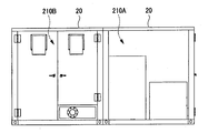
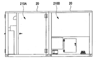
도 1은, 실시 형태 1에 따른 고형 연료 제조 장치(10)를 나타내는 정면도이다. 고형 연료 제조 장치(10)는, 도 1에 도시한 바와 같이, 크게 구별하여 혼합물 생성 장치(10A: 혼합물 생성 수단)와 혼합물 건조 장치(10B)로 이루어진다. 고형 연료 제조 장치(10)는, 본 실시 형태 1에서는, 목적지까지 수송하는 화물용 컨테이너(20)의 실내에 설치 가능한 크기로 구성되고, 구체적으로는, 예를 들어 ISO 규격에 준한, 소위 20ft의 해상 운송용 드라이 컨테이너(실내 치수: 길이 5.900m, 폭2.350m, 높이 2.390m)의 실내에 설치되는 것을 전제로 구성되어 있다.1 is a front view showing a solid
또한, 고형 연료 제조 장치(10)는, 화물용 컨테이너(20)의 실내에 한정하여 설치되는 것이 아니라, 화물용 컨테이너(20)를 사용하지 않고, 건물 내의 바닥에 설치하는 경우도 있다. 이 경우에는, 고형 연료 제조 장치(10)는, 화물용 컨테이너(20)에 알맞은 치수로 구성될 필요는 없다.The solid
혼합물 생성 장치(10A)는, 수분을 함유하는 가연성 폐기물(1: 도 13 참조)과, 이 가연성 폐기물(1)로부터 수분의 제거를 재촉하는 탈수 처리액(2: 탈수 처리제)을 혼련한 혼합물(3)을 생성하는 장치이다. 혼합물 생성 장치(10A)는, 고형 연료의 소재인 가연성 폐기물(1)을 투입하는 원료 투입구(12)와, 후술하는 탈수 처리액(2)을 주입하는 탈수 처리액 주입구(13)와, 가연성 폐기물(1)과 탈수 처리액(2)을 주지 기술에 의해 혼련하는 혼련부(14)와, 혼련부(14)에서 혼련된 혼합물(3)을 외부로 토출하는 압출부(15)를 갖고, 이들 모두가 제1 프레임(11)에 적재되어 있다.The
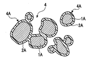
여기서, 탈수 처리액(2)에 대하여, 도 13 내지 도 15를 이용하여 설명한다. 도 13은, 처리 대상인 하수 오니를 구성하는 입상체(1A)를 나타내는 설명도이며, 도 13에 도시한 입상체 표면에 탈수 처리액(2)이 접촉된 상태를, 도 14에 도시한다. 도 15는, 피복 입상체(4A)를 나타내는 설명도이다. 탈수 처리액(2)은, 합성 수지를 함유한 에멀션으로 이루어진다. 구체적으로는, 탈수 처리액(2)은, 예를 들어 아크릴 수지, 우레탄 수지, 또는 아세트산 비닐 수지 등의 합성 수지를 함유한 것이며, 표 1에 나타낸 바와 같이, 다양한 합성 수지를 함유하는 에멀션을, 물로 적절히 희석한 것이다.Here, the

이 탈수 처리액(2)은, 혼합물 생성 장치(10A)에 의해, 가연성 폐기물(1)을 구성하는 입상체(1A)와 혼합한 혼합물(3)을 생성하고, 도 13 내지 도 15에 도시한 바와 같이, 탈수 처리액(2)을 입상체(1A)의 표면에 접촉시키면, 가연성 폐기물(1)에 있어서, 입상체(1A)끼리의 사이에 형성되는 공간(1B)에 탈수 처리액(2)이 들어가고, 입상체(1A)의 표면에 균일하게 피복하는 특성을 갖고 있다. 또한, 전술한 합성 수지를 포함하는 탈수 처리액(2)에는, 입상체(1A)의 건조를 촉진시키는 작용을 비교적 크게 하는 특성이 있다.This
또한, 도 15에 도시한 바와 같이, 전술한 합성 수지로 이루어지는 합성 수지 피막(2A)은, 발수성을 갖고 있으며, 혼합물(3)을 건조시켜 생성한 고형 연료인 건조 가연 물질(4)이 저장되어 있을 때라도, 건조 가연 물질(4)에의 흡습을 저감할 수 있고, 이 합성 수지 피막(2A)은, 건조 가연 물질(4)의 함수율의 증가나, 건조 가연 물질(4)에 점착성을 띠는 것을 억제하는 특성을 구비하고 있다. 또한, 본 실시 형태에서는, 함수율 w(질량%)는, 가연성 폐기물(1), 혼합물(3), 건조 가연 물질(4) 등의 측정 대상물의 전체 중량 W(㎏)에 차지하는 수분 함유량(수분 중량) h(㎏)의 비율이며, 하기 식 1에 의해 산출된다.15, the
[식 1][Formula 1]
w=h/W×100w = h / W x 100
이와 같은 특성을 갖는 탈수 처리액(2)을 사용한 혼합물(3)의 건조 공정에서는, 후술하는 혼합물 건조 장치(10B)에 의해 혼합물(3)을 온도가 20℃ 정도의 외기 AR에 의한 송풍으로 건조시키면, 입상체(1A) 표면에 부착된 탈수 처리액(2)이 건조하여 이루어지는 합성 수지 피막(2A)이 형성됨과 함께, 입상체(1A)에 포함하는 수분이 증발한다.In the step of drying the mixture 3 using the
이에 의해, 함수율이 저감된 입상체(1A)와, 그 표면을 피복하는 합성 수지 피막(2A)으로 이루어지는 피복 입상체(4A)가 생성된다. 또한, 건조에 수반되어 혼합물(3)이 수축함으로써, 혼합물(3)이 작게 분할하여 세분화되기 쉬워진다. 따라서, 합성 수지 피막(2A)을 개재하여, 서로 밀착된 복수의 피복 입상체(4A)로 이루어지는 건조 물질(4)이 생성된다.As a result, a
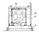
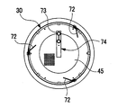
다음으로, 혼합물 건조 장치(10B)에 대하여, 설명한다. 도 2는, 고형 연료 제조 장치(10)의 평면도이다. 도 3은, 고형 연료 제조 장치(10)의 좌측 측면도이며, 그 우측 측면도를 도 4에 도시한다. 혼합물 건조 장치(10B)는, 회전 드럼(30: 혼합물 수용 수단)과, 흡기구(33: 흡기 수단)와, 환기 팬(41: 배기 수단)과, 히트 펌프(46: 승온 수단)와, 모터(51: 구동 수단)와, 조작 제어반(60: 제어 수단)과, 블레이드(72: 도 6 참조)(파쇄 수단) 등을 갖고 있다.Next, the
혼합물 건조 장치(10B)에서는, 그 설치면과의 높이를 조정 가능한 높이 조정 볼트(22)와, 당해 혼합물 건조 장치(10B)의 이동 시에 달아 올리는 반송용 훅(23)이, 외형이 사각 프레임 형상의 제2 프레임(21)에 설치되어 있다. 이 제2 프레임(21)에는, 모터(51), 드럼 하측 지지부(56), 드럼 상측 지지부(57), 및 조작 제어반(60) 등이 적재되어 있다.In the
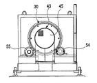
회전 드럼(30)은, 원통 형상으로 자전 가능하게 구성되고, 내부 공간(30S: 도 6 참조)에 혼합물(3)을 수용하는 드럼으로서, 본 실시 형태 1에서는, 혼합물(3)을 내부 공간(30S)에 투입한 양만큼 처리하는 뱃치 처리식 회전 드럼이다. 이 회전 드럼(30)은, 2개의 구동 롤러(54)와, 4개의 종동 롤러(55)에 의해 지지되어 있다. 구동 롤러(54)는, 제2 프레임(21)에 적재된 4군데의 드럼 하측 지지부(56) 중, 2군데의 드럼 하측 지지부(56)에, 각각 회전 가능하게 축 지지되어 있다.The
또한, 회전 드럼(30) 외주에는, 롤러 주행면(58)이 2군데 형성되어 있다. 롤러 주행면(58)은, 회전하는 구동 롤러(54)가 구름 이동하면서 접촉하여 구름 압축하는 면이며, 구동 롤러(54)의 회전력에 의해, 회전 드럼(30)에 회전력이 전달되고, 롤러 주행면(58)에 접촉하는 종동 롤러(55)가 종동적으로 구름 이동하면서, 회전하는 회전 드럼(30)을 보유 지지한다.In addition, two roller running surfaces 58 are formed on the outer periphery of the
구체적으로는, 4개 중, 2개의 종동 롤러(55)는, 나머지 2군데의 드럼 하측 지지부(56)에 각각 회전 가능하게 축 지지되어 있으며, 나머지 2개의 종동 롤러(55)는 각각, 도 1 및 도 3에 도시한 바와 같이, 제2 프레임(21)에 세워 설치된 2군데의 드럼 상측 지지부(57)에 회전 가능하게 축 지지되어 있다. 드럼 상측 지지부(57)는, 종동 롤러(55)의 축심 높이를 상하 방향으로 조정 가능하게 구성되어 있으며, 드럼 상측 지지부(57)에 축 지지한 종동 롤러(55)의 높이를 위치 조정함으로써, 구동 롤러(54)에 의한 회전 드럼(30)에의 여압이 조정된다.Specifically, two of the four driven
모터(51)는, 회전 드럼(30)을 회전시키는 구동원이며, 모터 출력축(52)과 연결하는 동력 전달축(53)의 회전에 의해, 회전력이 구동 롤러(54)에 전달되는 구조로 되어 있다. 조작 제어반(60)은, 혼합물 생성 장치(10A)의 작동 ON/OFF, 회전 드럼(30)의 회전 동작 ON/OFF, 환기 팬(41)의 작동 ON/OFF, 히트 펌프(46)의 작동 ON/OFF 등, 당해 고형 연료 제조 장치(10)의 조작을 행하는 조작 기능을 구비하고 있다.The
또한, 이 조작 제어반(60)은, 타이머 기능, 모터(51)의 회전 수를 제어하는 인버터, 환기 팬(41)의 풍량을 제어하는 인버터, 회전 드럼(30)의 회전 수 및 회전 방향의 설정이나 변경 등의 당해 고형 연료 제조 장치(10)의 각 동작에 있어서의 동작 제어나, 프로그래밍을 행하는 시퀀서 등의 전기적 제어 기기도 구비하고 있다.The
4군데의 드럼 하측 지지부(56)에는 각각, 하중 센서(59)가 배치되어 있다. 4개의 하중 센서(59)는, 내부 공간(30S)에 수용된 혼합물(3)을 포함하는 회전 드럼(30) 전체에 걸리는 하중 중, 각 드럼 하측 지지부(56)의 소정 부위(예를 들어, 구동 롤러(54)의 회전축 또는 그 베어링, 종동 롤러(55)의 회전축 또는 그 베어링 등)에 작용하는 하중을 각각 검출한다. 하중 센서(59)는, 조작 제어반(60)과 전기적으로 접속되어 있으며, 하중 센서(59)의 검출 신호가, 조작 제어반(60)으로 출력된다.A
이에 의해, 회전 드럼(30)의 내부 공간(30S)에 수용된 혼합물(3)이, 내부 공간(30S)의 어느 부근에 있는 것인가에 대하여, 작업자는, 각 하중 센서(59)로부터 검출된 신호에 기초하여, 조작 제어반(60)에 의해 확인할 수 있다. 즉, 회전 드럼(30)의 내부 공간(30S)에 있어서, 혼합물(3)이 치우치고, 회전 드럼(30) 전체의 무게 중심이 흡기구(33)측 또는 배기구(45)측으로 치우쳤을 때의 각 하중 센서(59)의 검출 신호에 기초하여, 회전 드럼(30) 전체의 무게 중심 위치를 원 상태로 되돌리도록, 회전 드럼(30)의 회전 방향이 반전되고, 혼합물(3)이 치우친 위치에 머물지 않도록, 회전 드럼(30)의 회전이 조작 제어반(60)에 의해 제어되고 있다.By this means, the operator can recognize which part of the
또한, 본 실시 형태 1에서는, 조작 제어반(60)에 입력된 하중 센서(59)로부터의 검출 신호에 기초하여, 조작 제어반(60) 내의 전기적 제어 기기가, 회전 드럼(30)에 있어서의 회전 수 변경, 회전 방향 변경, 회전과 정지를 복합적으로 조합한 동작 등의 동작 제어를, 자동으로 행한다.In the first embodiment, the electric control device in the
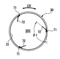
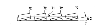
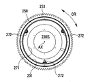
다음으로, 본 발명의 파쇄 수단인 블레이드(72)에 대하여, 설명한다. 도 6은, 도 1 중, B-B 화살표 방향에서 본 뱃치식 회전 드럼(30)의 내부 모습을 나타낸 도면이며, 블레이드(72)의 부착 위치를 설명하는 도면이다. 블레이드(72)는, 회전 드럼(30)의 내부 공간(30S)에 수용한 혼합물(3)을 파쇄하는 부재로서, 회전 드럼(30)의 내주벽(31)을 따라 배치되고, 회전 드럼(30)의 자전 운동에 의해, 혼합물(30)(또는 건조 가연 물질(4))을 내부 공간(30S)의 상방으로 쓸어 올림과 함께, 내부 공간(30S)의 상방으로부터 하방으로 자유 낙하 가능한 구조로 형성되어 있다.Next, the
구체적으로는, 각 블레이드(72)는, 예를 들어 굽힘 가공에 의해 판재를, 2변이 이루는 굽힘 각도 θ1이 135°(도 6에 도시한 바와 같이, 내주벽(31)에 있어서의 블레이드 브래킷(71)의 부착 위치의 접선 방향에 대하여, 블레이드(72)의 1변으로 되는 일면부를 45°로 기운 상태)인 대략 ㄱ자 형상, 또는 90°인 L자 형상으로 굴곡시켜 형성되어 있다. 블레이드(72)는, 그 또 1변으로 되는 다른 면부를, 회전 드럼(30)의 내주벽(31)에 고착된 판 형상의 블레이드 브래킷(71)에, 나사 체결로 고정하여 부착되어 있다.Specifically, each of the
또한, 본 실시 형태 1에서는, 도 6에 있어서, 블레이드 브래킷(71)은, 내주벽(31)에, 회전 드럼(30)의 주위 방향 CR에 대하여, 120°등분의 위치에 3군데 배치되어 있지만, 블레이드 브래킷(71)의 부착하는 위치, 부착하는 수, 주위 방향 CR에 대하여 부착하는 간격은, 건조 처리하는 혼합물(3)의 물성에 따라서, 적절히 변경 가능하며, 본 실시 형태 1에 한정되는 것은 아니다.6, the
도 7은, 도 2 중, C-C 화살표 방향에서 본 도면이며, 블레이드(72)의 배치 위치를 설명하는 도면이다. 도 8은, 변형예 1에 따른 블레이드(72)의 배치 위치의 설명도이다. 도 9는, 변형예 2에 따른 블레이드(72)의 배치 위치의 설명도이다.Fig. 7 is a view seen from the direction of arrows C-C in Fig. 2, and is a view for explaining the arrangement positions of the
또한, 도 7 내지 도 9에서는, 블레이드 브래킷(71)에 대하여 블레이드(72)를 배치하는 위치나 방향, 배치하는 수, 굽힘 각도 θ1, 부착 각도 θ2는, 단순히 예시한 것에 지나지 않으며, 본 실시 형태 1에 한정되는 것이 아니라, 적절히 변경 가능하다.7 to 9, the position and direction of the
또한, 도 7 내지 도 9에서는, 3개의 블레이드 브래킷(71) 중, 1개 블레이드 브래킷(71)에 부착된 블레이드(72)에 대하여 도시한 것이지만, 3개의 블레이드 브래킷(71) 모두, 블레이드(72)의 배치 위치나 방향, 배치하는 수, 굽힘 각도 θ1, 부착 각도 θ2가 동일하여도 된다. 또는, 도 7 내지 도 9의 각 도면에 각각 나타낸 블레이드(72)의 배치 형태가, 3개의 블레이드 브래킷(71)마다 서로 다르게 나뉘어 있어도 된다.7 to 9 show the
블레이드(72)는, 회전 드럼(30)의 축 방향 AX(도 1 중, 좌우 방향)를 따라서, 1개의 블레이드 브래킷(71)에 복수(도 7에서는 4개) 부착되어 있다. 구체적으로는, 도 7에 도시한 바와 같이, 1개의 블레이드 브래킷(71)에, 회전 드럼(30)의 드럼 개폐 도어(32)측(도 7 중, 좌측)에 위치하는 블레이드(72)가, 시계 방향으로 10°정도 기울어 부착되어 있음과 함께, 배기구(45)측(도 7 중, 우측)에 위치하는 블레이드(72)가, 반시계 방향으로 10°정도 기울어 부착되어 있다.The
(변형예 1)(Modified Example 1)
도 8에 도시한 바와 같이, 1개의 블레이드 브래킷(71)에 부착되어 있는 모든 블레이드(72)가, 반시계 방향으로 10°정도 기울어 부착되어 있다.As shown in Fig. 8, all the
(변형예 2)(Modified example 2)
도 9에 도시한 바와 같이, 1개의 블레이드 브래킷(71)에 부착되어 있는 모든 블레이드(72)가, 시계 방향으로 10°정도 기울어 부착되어 있다. 또한, 도 7 내지 도 9에 도시한 블레이드(72)가, 블레이드 브래킷(71)에 대하여 경사져서 부착하는 각도는, 10°정도에 한하지 않으며, 건조 처리하는 혼합물(3)의 점도 등에 따라서, 적절히 변경 가능하다.As shown in Fig. 9, all the
회전 드럼(30)은, 축 방향 AX(도 1 중, 좌우 방향)의 일방측(도 1 중, 좌측)의 개구부에, 개폐 가능한 드럼 개폐 도어(32)를 갖고, 도 3에 도시한 바와 같이, 드럼 개폐 도어(32)의 내부에, 통기 가능한 메쉬 구조로 형성된 흡기구(33)를 구비하고 있다. 흡기구(33)는, 환기 팬(41)에 의해 흡인되는 외기 AR을, 회전 드럼(30)의 내부 공간(30S)에 도입하는 개구부이다. 도 10은, 도 3 중, D-D 화살표 방향에서 본 뱃치식 드럼 내를 나타내는 도면이며, 레이크(34: rake)의 설명도이다.The
레이크(34)는, 드럼 개폐 도어(32)의 흡기구(33)의 하방 위치에 설치되어 있다(도 1 및 도 10 참조). 레이크(34)는, 마치 빗과 같이, 복수 개의 봉재(棒材)를, 간극을 두고 평행으로 정렬한 부재이며, 회전 드럼(30)의 내부 공간(30S)에서 건조 처리하고 있는 혼합물(3)이 레이크(34)에 접촉함으로써, 세분화하는 기능을 갖는다. 도 5는, 도 1 중, A-A 화살표 방향에서 본 도면이며, 도면을 보기 쉽게 하기 위해서, 블레이드 및 스크레이퍼와, 이들에 관계하는 각 부재의 도시를 생략한 도면이다.The
회전 드럼(30)의 축 방향 AX의 타방측(도 1 중, 우측)의 개구부는, 통 형상의 덕트(43)와, 상대적으로 회전 가능하게 연결되어 있다. 이 덕트(43)는, 커버(42)에 의해 덮인 환기 팬(41)에 의해, 외부로부터 흡기구(33)에 흡인된 외기 AR을 회전 드럼(30)의 내부 공간(30S)에 송풍하여 공급하는 중간 유로로서 기능한다. 회전 드럼(30)과 덕트(43)의 사이에는, 도 5에 도시한 바와 같이, 배기구(45)가 설치되어 있다.The opening on the other side (the right side in Fig. 1) of the axial direction AX of the
배기구(45)는, 내부 공간(30S)에 투입한 혼합물(3)이나, 이 혼합물(3)의 건조 처리를 행하고 있는 동안에 세분화된 건조 처리 종료 직전의 건조 가연 물질(4)을 덕트(43) 내로 유출되는 것을 방지할 수 있는 비교적 미세한 개공률의 메쉬 구조로 형성되어 있다. 덕트(43)는, 배기구(45)와 환기 팬(41)의 사이에 접속되어 있다. 회전 드럼(30)의 내부 공간(30S) 내의 분위기는, 환기 팬(41)에 의해, 배기구(45)를 통하여 덕트(43) 내에 흡인되어 외부로 배기된다.The
도 11은, 도 2 중, C-C 화살표 방향에서 본 도면이며, 스크레이퍼(74)의 설명도이다. 도 12는, 도 11 중, E-E 화살표 방향에서 본 스크레이퍼(74)를 나타내는 설명도이다. 배기구(45)에는, 도 11 및 도 12에 도시한 바와 같이, 스크레이퍼(74)가 배치되어 있다. 스크레이퍼(74)는, 배기구(45)의 메쉬에 부착된 혼합물(3)(또는 건조 가연 물질(4))을 메쉬로부터 불식하는 브러시 형상의 부재이며, 회전 드럼(30)에 배치된 스크레이퍼 부착 부재(73)에 고정 설치되어 지지되어 있다.Fig. 11 is a view of the
이 스크레이퍼(74)는, 배기구(45)의 메쉬에 있어서 직경 방향의 절반 이상의 범위를 불식 가능한 크기로 형성되어 있다. 이에 의해, 스크레이퍼(74)의 털끝이 배기구(45)의 메쉬의 일정한 위치에 접촉하고 있으면, 회전 드럼(30)의 회전에 수반하여, 배기구(45)의 메쉬도 자전하기 때문에, 스크레이퍼(74)는 배기구(45)의 메쉬 전체에 걸쳐 부착된 혼합물(3)(또는 건조 가연 물질(4))을 배기구(45)의 메쉬로부터 제거할 수 있다.The
도 1에 도시한 바와 같이, 혼합물 생성 장치(10A)의 제1 프레임(11)의 하측에는, 히트 펌프(46)가 배치되어 있다. 히트 펌프(46)의 에어 토출부(48)는, 도 1 내지 도 3에 도시한 바와 같이, 혼합물 건조 장치(10B)의 드럼 개폐 도어(32)에 접속되어 있다. 외기 AR의 온도가 20℃ 미만인 경우, 히트 펌프(46)가 에어 흡기부(47)로부터 도입된 외기 AR을, 20℃ 이상 및 30℃ 이하의 범위에서 승온한다. 승온된 외기 AR은, 에어 토출부(48)를 통하여, 회전 드럼(30)의 내부 공간(30S)에 공급된다.As shown in Fig. 1, a
다음으로, 고형 연료 제조 장치(10)를 사용한 고형 연료 제조 방법에 대하여 설명한다. 처음에, 혼합물 생성 장치(10A)에 의해, 소정량(예를 들어, 1 뱃치당 수십 내지 수백 ㎏)의 가연성 폐기물(1)을 원료 투입구(12)에 투입하고, 탈수 처리액(2)을 탈수 처리액 주입구(13)에 주입하여, 가연성 폐기물(1)과 탈수 처리액(2)을 혼련부(14)에서 혼련하여 혼합물(3)을 생성하고, 압출부(15)로부터 토출한다.Next, a solid fuel production method using the solid
본 실시 형태 1에서는, 가연성 폐기물(1)은 97%, 탈수 처리액(2)은 3%의 중량 비율로 혼합되고, 혼합한 가연성 폐기물(1)과 탈수 처리액(2)의 함수율은, 대략 70 내지 80%이다. 또한, 회전 드럼(30)의 내부 공간(30S)에 투입하는 혼합물(3)의 총 체적은, 내부 공간(30S) 전체의 용적비로, 1/2 이하의 범위 내이며, 보다 바람직하게는, 내부 공간(30S)에 투입하는 혼합물(3)의 양은, 내부 공간(30S)의 내경에 대응하는 높이에 대하여, 1/3 이하의 범위 내이면 된다.In the first embodiment, the water content of the
그 이유로서, 내부 공간(30S)에 투입한 혼합물(3)은, 회전 드럼(30)의 회전에 의해, 복수의 블레이드(72)로 내부 공간(30S)의 상방으로 쓸어 올림과 함께, 내부 공간(30S)의 상방으로부터 하방으로 자유 낙하하는 복잡한 운동을 반복하면서, 환기 팬(41)에 의해 흡인되는 외기 AR에 접촉하여 건조하고, 세분화된다. 이때, 혼합물(3)의 투입량이, 전술한 범위 내이면, 혼합물(3)은 적극적으로 교반되고, 외기 AR에 접촉하는 혼합물(3)의 표면적을 보다 크게 할 수 있다. 그로 인해, 혼합물(3)의 건조가 촉진되고, 수분의 증발과 함께 혼합물(3)이 수축함으로써, 혼합물(3)이 작게 분할되어 세분화되기 쉬워지기 때문이다.The reason for this is that the mixture 3 charged into the
작업자는, 압출부(15)로부터 토출된 혼합물(3)을 회전 드럼(30)의 내부 공간(30S)에 투입하고, 드럼 개폐 도어(32)에 의해 내부 공간(30S)을 폐색한다. 계속해서, 작업자는 혼합물(3)의 건조 처리 공정을 행하기 전에, 내부 공간(30S)에 혼합물(3)을 투입한 직후의 회전 드럼(30) 전체의 중량을, 하중 센서(59)에 의해 검출함으로써, 혼합물(3)의 건조 처리 전 중량을 미리 계측해 둔다. 계속해서, 조작 제어반(60)을 조작하여, 예를 들어 회전 드럼(30)을 주위 속도 140㎜/sec.로 일 방향으로 회전시켜서, 환기 팬(41)의 작동에 의해 외기 AR을, 풍속 3 내지 6m/sec. 등의 조건으로 내부 공간(30S)에 도입한다. 외기 AR의 온도가 20℃ 미만인 경우에는, 히트 펌프(46)를 작동시켜서, 내부 공간(30S)에 유입되는 외기 AR을, 온도 20℃ 이상 및 30℃ 이하의 범위에서 승온한다.The worker puts the mixture 3 discharged from the extruding
그리고, 혼합물 건조 장치(10B)를, 이 상태에서, 예를 들어 5시간 정도, 운전을 계속한다. 그동안 내부 공간(30S)에 투입한 혼합물(3)은, 각 블레이드(72)에 의해 내부 공간(30S)의 상방으로 쓸어 올림과 함께, 내부 공간(30S)의 상방으로부터 하방으로 자유 낙하를 반복하면서, 4개의 하중 센서(59)의 검출 신호에 기초하는 회전 드럼(30)의 동작 제어에 의해, 축 방향 AX를 따른 왕래를 반복한다.Then, the
혼합물 건조 장치(10B)의 드럼 개폐 도어(32)에는, 흡기구(33)가 배기구(45)와 대향하는 위치에 설치되어 있기 때문에, 환기 팬(41)에 의해 외기 AR이, 흡기구(33)를 통하여 내부 공간(30S)에 유입되어도, 내부 공간(30S)으로부터의 배기 EG가 배기구(45)로부터 배출되기 쉬어, 흡기 및 배기 효율이 높아지고 있다. 그로 인해, 건조 처리 중 수분이 혼합물(3)로부터 증발하여도, 내부 공간(30S)의 분위기는 포화 상태가 되지 않고, 혼합물(3)을 한창 교반하고 있을 때, 이 혼합물(3)로부터 수분이 내부 공간(30S)의 분위기에 증발되는 것을 저지하지 못한다.The outside air AR is discharged by the
그리고, 타임 업 후, 작업자는 혼합물(3)에 있어서의 수분의 함유율을, 하중 센서(59)의 검출 신호에 의해 측정한다. 구체적으로는, 작업자는, 혼합물(3)의 건조 처리 공정의 타임 업 후에, 내부 공간(30S)에 혼합물(3)을 투입된 채의 회전 드럼(30) 전체의 중량을, 하중 센서(59)에 의해 검출함으로써, 혼합물(3)의 건조 처리 후 중량을 계측한다. 그리고, 작업자는 혼합물(3)의 건조 처리 전 중량에 대하여 혼합물(3)의 건조 처리 후 중량의 비율(혼합물(3)에 함유되는 수분의 함수율)을 구하고, 이 함수율이 20% 이하인지 여부를 판단한다. 함수율이 20%를 초과하면, 작업자는 조작 제어반(60)을 다시 조작하여, 함수율 20% 이하로 될 때까지, 혼합물(3)의 건조 처리 시간을 연장하고, 함수율 20% 이하를 포함하고 있으면, 건조 처리를 종료한다.Then, after time-up, the worker measures the moisture content in the mixture (3) by the detection signal of the load sensor (59). More specifically, the operator sets the weight of the entire
이와 같이, 내부 공간(30S)에 투입한 혼합물(3)은, 혼합물 건조 장치(10B)에 의해 함수율 20% 이하로 건조 처리되고, 약 4,000 내지 5,000kcal/㎏의 에너지를 갖는 건조 가연 물질(4)로 된다. 이와 같이 하여, 가연성 폐기물(1)에 포함되어 있는 수분을 건조시키고, 파쇄하여 1㎤보다 작은 펠릿 형상의 고형 연료로서, 건조 가연 물질(4)을 생성할 수 있다.As described above, the mixture 3 charged into the
여기서, 본 실시 형태 1의 고형 연료 제조 장치(10)를 사용한 고형 연료 제조 방법에 대하여, 그 유의성을 확인하는 조사를 행하였다. 확인 조사는, 가연성 폐기물(1)로서, 폐기된 양배추를 시료로 하는 테스트 1과, 부식된 귤을 시료로 하는 테스트 2를 실시하였다.Here, the solid fuel producing method using the solid
〔테스트 1과 테스트 2의 공통 조건〕[Common conditions between
(1) 가연성 폐기물(1)과 탈수 처리액(2)의 혼합 중량 비율; 97:3(1) the mixing weight ratio of the flammable waste (1) to the dehydrating liquid (2); 97: 3
(2) 혼합 전의 가연성 폐기물(1)의 표면 온도; 28℃(2) surface temperature of
(3) 건조 처리 시간; 6시간(3) drying treatment time; 6 hours
(4) 함수율의 분석; 전문 기관에 있어서, 건조 처리한 건조 가연 물질(4)을 수분계를 사용하여 1시간마다 함수율을 계측(4) Analysis of water content; In a professional organization, the moisture content of the dried flammable material (4), which has been dried, is measured every hour using a moisture meter
(5) 함수율의 계측; 5분간, 시료를 교반한 후, 가열 건조식 수분계(A&D사 제조 기종 ML-50)를 사용하여 계측(5) Measurement of water content; After stirring the sample for 5 minutes, measurement was carried out using a heating dry type moisture meter (model ML-50 manufactured by A & D)
〔테스트 1의 결과〕[Results of Test 1]
테스트 1에서는, 혼합 전의 양배추의 함수율은 92%이었지만, 양배추로부터 생성된 건조 가연 물질(4)의 함수율은, 건조 처리 개시 후 6시간에 13.5%로 되고, 이 건조 가연 물질(4)의 표면 온도는 30.1℃이었다. 또한, 건조 가연 물질(4)은 쌀 한 톨의 크기 정도까지 파쇄되고, 펠릿 형상의 고형 연료가 되어 있는 것이 확인되었다. 또한, 테스트 1에 따른 건조 가연 물질(4)을 분석한 바, 양배추로부터 생성된 건조 가연 물질(4)의 발열량은, 18,800J/g이었다.In the
〔테스트 2의 결과〕[Results of Test 2]
테스트 2에서는, 혼합 전의 귤의 함수율은 80.6%이었지만, 부식된 귤로부터 생성된 건조 가연 물질(4)의 함수율은, 건조 처리 개시 후 6시간에 21.4%로 되고, 이 건조 가연 물질(4)의 표면 온도는 26.1℃이었다. 또한, 건조 가연 물질(4)은 대략 0.8㎤ 정도까지 파쇄되고, 펠릿 형상의 고형 연료가 되어 있는 것이 확인되었다. 또한, 테스트 2에 따른 건조 가연 물질(4)을 분석한 바, 부식된 귤로부터 생성된 건조 가연 물질(4)의 발열량은, 19,800J/g이었다.In the
테스트 1, 2에서는, 함수율 80% 이상의 수분을 함유하는 가연성 폐기물(1)에, 탈수 처리액(2)을 약간 주입하여 혼련한 후, 그 생성물인 혼합물(3)에, 6시간 정도, 거의 상온인 20℃ 정도의 외기 AR을 송풍하면서 교반하는 것만으로, 고형 연료로서 사용할 수 있는 목표의 함수율 20% 정도의 건조 가연 물질(4)을 생성할 수 있어, 고형 연료 제조 장치(10)를 사용한 고형 연료 제조 방법에 유의성이 있음을 확인할 수 있었다. 게다가, 건조 가연 물질(4)의 생성 처리의 과정에서는, 가연성 폐기물(1)이 종래 기술에 의한 고형 연료 제조 장치와 같이, 100℃ 가까운 고온 하의 분위기에 노출되지 않기 때문에, 악취가 완전히 발생하는 일도 없다.In Tests 1 and 2, the dehydrating
전술한 구성을 갖는 본 실시 형태 1에 따른 고형 연료 제조 장치(10)와, 이 장치를 사용한 고형 연료 제조 방법의 작용·효과에 대하여 설명한다.The operation and effect of the solid
고형 연료 제조 장치(10)는 수분을 함유하는 가연성 폐기물(1)과, 가연성 폐기물(1)로부터 수분의 제거를 촉진시키는 탈수 처리액(2)이 혼련된 혼합물(3)을 생성하는 혼합물 생성 장치(10A)와, 원통 형상으로 자전 가능하게 구성되고, 내부 공간(30S)에 혼합물(3)을 수용하는 회전 드럼(30)과, 회전 드럼(30)에 외기 AR을 도입하는 환기 팬(41)을 구비한다.A solid fuel producing apparatus (10) is provided with a mixture producing apparatus (1) for producing a mixture (3) in which flammable waste (1) containing moisture is mixed with a dehydrating treatment liquid (2) A
또한, 내부 공간(30S)으로부터의 배기 EG를 외부로 배출하는 배기구(45)와, 회전 드럼(30)을 회전시키는 모터(51)와, 모터(51)의 움직임을 제어하는 조작 제어반(60)과, 내부 공간(30S)에 수용한 혼합물(3)을 파쇄하는 블레이드(72)를 구비한다. 그리고, 탈수 처리액(2)은, 합성 수지를 함유한 에멀션으로 이루어지는 처리제이다. 블레이드(72)는, 회전 드럼(30)의 내주벽(31)을 따라 배치되고, 회전 드럼(30)의 자전 운동에 의해, 혼합물(3)을 내부 공간(30S)의 상방으로 쓸어 올림과 함께, 내부 공간(30S)의 상방으로부터 하방으로 자유 낙하 가능한 구조로 형성되어 있다.An
이에 의해, 고형 연료 제조 장치(10)에서는, 가연성 폐기물(1)에 포함하는 수분은, 탈수 처리액(2)에 의해 증발되기 쉬워지게 되어 있으며, 혼합물(3)의 교반과, 고온으로 가열하지 않고, 거의 상온에 가까운 20℃ 정도의 외기 AR을 송풍하는 것만으로, 고형 연료로서, 블레이드(72) 및 레이크(34)에 의해 세분화된 건조 가연 물질(4)을 생성할 수 있다. 또한, 고형 연료 제조 장치(10)에서는, 그 구성이나 구조가 간단한 동시에, 가연성 폐기물(1)로부터 고형 연료인 건조 가연 물질(4)을 생성하지만, 가연성 폐기물(1)을 가열하는 열원의 설비가 불필요하며, 그 열원에 공급하는 에너지(연료)도 필요로 하지 않는다.Thus, in the solid
그로 인해, 고형 연료 제조 장치(10)에서는, 종래 기술의 고형 연료 제조 장치에 비하여, 이니셜 코스트와 러닝 코스트 모두 고가의 비용이 들지 않는다는 이점이 있다. 또한, 가연성 폐기물(1)로부터 건조 가연 물질(4)을 효율적으로, 짧은 처리 시간에 생성할 수 있다. 게다가 건조 가연 물질(4)의 생성 시에 악취가 발생하지 않기 때문에, 방취 대책을 필요로 하지 않아 작업성도 좋다.Thereby, the solid
특히, 자치 단체에 있어서의 하수 오니 처리 외에, 식품 제조업체나 슈퍼마켓 등에서 발생한 식품 폐기물 등의 시설에서는, 예를 들어 하수 처리 시에 발생하는 유기 오니, 식품 폐기물 등, 유기계 폐기물인 가연성 폐기물이 매일, 대량으로 발생한다. 고형 연료 제조 장치(10)는, 이와 같은 가연성 폐기물로부터 건조 처리 후의 혼합물을 생성하는 데도, 예를 들어 수십 내지 수백 ㎏의 가연성 폐기물(1)을 수 시간 등의 처리 시간에 건조 처리하는 높은 처리 능력을 갖고 있기 때문에, 이러한 시설에 있어서, 가연성 폐기물(1)을 고형 연료화하는 처리를 행하는 데 적합한 장치로 될 수 있다.In particular, in addition to sewage sludge treatment in local governments, facilities such as food waste generated in food manufacturers and supermarkets, such as organic sludge generated during sewage treatment, food wastes, and combustible wastes such as organic wastes, . The solid
따라서, 본 실시 형태 1에 따른 고형 연료 제조 장치(10)에 의하면, 가연성 폐기물(1)인 하수 오니에 포함되는 수분을 짧은 시간에 제거하여, 저비용으로 고형 연료인 건조 가연 물질(4)을 생성할 수 있다는 우수한 효과를 발휘한다.Therefore, according to the solid
또한, 본 실시 형태 1에서는, 회전 드럼(30)의 내주벽(31)에 부착된 블레이드(72)는, 회전 드럼(30)의 축 방향 AX와 주위 방향 CR에 대하여, 복수 부분에 적어도 부착 각도, 또는 부착 방향을 바꿔 배치되어 있다. 또한, 하중 센서(59)가 회전 드럼(30)을 지지하는 위치에 배치되고, 조작 제어반(60)이 하중 센서(59)의 검출 신호에 기초하여, 모터(51)의 움직임을 제어하고 있다.The
그로 인해, 회전 드럼(30)의 내부 공간(30S)에서는, 혼합물(3)이 남김없이 교반되고, 흡기구(33)로부터 도입되는 외기 AR에 노출되는 혼합물(3)의 표면적을, 보다 크게 할 수 있어, 수분의 증발과, 혼합물(3)의 세분화가 촉진되기 쉬워진다.Thereby, in the
또한, 본 실시 형태 1에서는, 회전 드럼(30)은 뱃치 처리식 회전 드럼이므로, 고형 연료화하는 처리 대상의 가연성 폐기물(1)이 비교적 소량인 경우에, 고형 연료 제조 장치(10)의 사용은 적합하다. 또한, 고형 연료 제조 장치(10)는 조밀하며, 설비 비용도 저렴하다.Further, in the first embodiment, since the
또한, 본 실시 형태 1에서는, 환기 팬(41)에 의해 도입되는 외기 AR의 온도가 20℃ 미만인 경우, 외기 AR을, 20℃ 이상 및 30℃ 이하의 범위에서 승온시키는 히트 펌프(46)를 구비하고 있으므로, 계절이나 환경에 의해 외기 AR의 온도가 20℃ 미만이더라도, 악취를 발생시키지 않고, 혼합물(3)에 포함되는 수분을, 회전 드럼(30)의 내부 공간(30S)의 분위기에, 효율적으로 증발시킬 수 있다.In the first embodiment, a
또한, 본 실시 형태 1에서는, 배기구(45)에 스크레이퍼(74)가 설치되어 있으므로, 환기 팬(41)에 의해 도입되는 외기 AR을, 회전 드럼(30)의 내부 공간(30S)에 송풍하는 데 있어서, 외기 AR의 흐름이, 배기구(45)의 메쉬 전체에 걸쳐 부착된 혼합물(3)(또는 건조 가연 물질(4))에 의해, 저해되는 것을 방지할 수 있다.In the first embodiment, since the
또한, 본 실시 형태 1에서는, 고형 연료 제조 장치(10)는 화물용 컨테이너(20)의 실내에 설치되어 있으므로, 실내에 고형 연료 제조 장치(10)를 설치한 화물용 컨테이너(20)를 고형 연료 제조 장치(10)의 설치 장소에 앵커를 박아 고정하는 것만으로, 고형 연료 제조 장치(10)의 설치가 완료되어 그 설치 작업이 용이하게 된다.The solid
또한, 본 실시 형태 1에서는, 고형 연료 제조 장치(10)를 사용하여, 가연성 폐기물(1)에 포함되어 있는 수분을 건조시키고, 파쇄하여, 1㎤보다 작은 펠릿 형상의 고형 연료인 건조 가연 물질(4)을 생성하므로, 건조 가연 물질(4)이 연소하기 쉬운 상태로 된다. 또한, 건조 가연 물질(4)은, 고형 연료를 연소시켜 열원을 발생하는 장치에 대하여 폭넓은 용도로 이용할 수 있다.Further, in
또한, 본 실시 형태 1에서는, 가연성 폐기물(1)은 적어도 하수 오니, 식품 폐기물, 동물의 배설물, 또는 식물성 폐기물 중 어느 하나를 대상으로 하고 있으므로, 가연성 폐기물(1)은 가연 성분을 포함한 채 함유되는 수분을 제거하면, 유효한 연료 자원으로서 활용할 수 있다.In the first embodiment, since the
(실시 형태 2)(Embodiment 2)
다음으로, 실시 형태 2에 따른 고형 연료 제조 장치(110)에 대하여, 도 16 내지 도 18을 이용하여 설명한다. 도 16은, 실시 형태 2에 따른 고형 연료 제조 장치(110)를 나타내는 정면도이며, 도 16에 도시한 고형 연료 제조 장치(110)의 평면도를 도 17에, 도 16 중, F-F 화살표 방향에서 본 연속식 회전 드럼(130)의 내부 모습을 나타내는 설명도를 도 18에, 각각 도시한다.Next, a solid
실시 형태 1의 고형 연료 제조 장치(10)에서는, 본 발명의 혼합물 형성 수단을, 뱃치 처리식 회전 드럼(30)으로 하였다. 본 실시 형태 2의 고형 연료 제조 장치(110)에서는, 본 발명의 혼합물 형성 수단이, 연속 처리식 회전 드럼(130)이며, 반입용 컨베이어(180)가 구성되어 있다. 이 외에, 주로 흡기 수단 및 배기 수단과, 고형 연료 제조 장치(110)를 수용하는 화물용 컨테이너의 사이즈와, 회전 드럼(130)의 회전 구동 구조 등이, 실시 형태 1과 상이하다.In the solid
그 이외의 부분은, 실시 형태 1과 마찬가지이다. 따라서, 실시 형태 1과 동일한 부분은 동일 부호를 사용하여, 실시 형태 1과 상이한 부분을 중심으로 설명하고, 그 밖에 대해서는 설명을 간략 또는 생략한다.The other parts are the same as those in the first embodiment. Therefore, the same parts as those of the first embodiment are denoted by the same reference numerals, and the description will be simplified or omitted except for the parts different from the first embodiment.
고형 연료 제조 장치(110)는, 도 1에 도시한 바와 같이, 크게 구별하여, 혼합물 생성 장치(10A)와 혼합물 건조 장치(110B)를 포함한다. 고형 연료 제조 장치(110)는, 본 실시 형태 2에서는, 목적지까지 수송하는 화물용 컨테이너(120)의 실내에 설치 가능한 크기로 구성되고, 구체적으로는, 예를 들어 ISO 규격에 준한, 소위 40ft 하이큐브(키높이형) 해상 운송용 드라이 컨테이너(실내 치수: 길이 12.030m, 폭 2.350m, 높이 2.700m)의 실내에 설치되는 것을 전제로 구성되어 있다.1, the solid
또한, 고형 연료 제조 장치(110)는, 화물용 컨테이너(120)의 실내에 한정하여 설치되는 것이 아니라, 화물용 컨테이너(120)를 사용하지 않고, 건물 내의 바닥에 설치하는 경우도 있다. 이 경우에는, 고형 연료 제조 장치(110)는 화물용 컨테이너(120)에 맞춘 치수로 구성될 필요는 없다.The solid
회전 드럼(130)은, 본 실시 형태 2에서는, 처리 전의 혼합물(3)을 축 방향 AX 일방측(도 16 중, 좌측)에 있는 내부 공간(130S)의 입구에 반입하고, 내부 공간(130S)을 축 방향 AX로 통과함으로써 처리되고, 타방측(도 16 중, 우측)에 있는 내부 공간(130S)의 출구로부터 처리 후의 혼합물(3)(건조 가연 물질(4))이 반출되는 연속 처리식 회전 드럼이다.The
회전 드럼(130)은, 제2 프레임(121)에 적재된 4군데의 드럼 하측 지지부(56)에, 각각 회전 가능하게 축 지지한 4개의 종동 롤러(55)에 의해, 지지되어 있다. 회전 드럼(130) 외주에는, 롤러 주행면(158)이 2군데에 형성되고, 2개 1조인 종동 롤러(55)가 롤러 주행면(158)과 접촉하여 종동적으로 구름 이동하면서, 회전하는 회전 드럼(130)을 보유 지지한다.The
이 회전 드럼(130) 외주에는, 외부 링 기어와 같이, 구동 체인(153)과 맞물림 가능한 복수의 외치를 단속적으로 형성한 체인 맞물림부(154)가 설치되어 있다. 모터(151)는, 회전 드럼(130)을 회전시키는 구동원이며, 모터 출력축(152)에 스프로킷이 연결되고, 구동 체인(153)이, 이 스프로킷과 체인 맞물림부(154)에 걸쳐 감겨 있으며, 모터 출력축(152)의 회전에 의해 회전 드럼(130)이 회전하도록 되어 있다.In the outer periphery of the
또한, 상기 스프로킷 및 구동 체인(153) 대신에, 모터 출력축(152)에 구동 기어(외치 기어)를 회전 드럼(130) 외주에 종동 기어(환 현상의 외치 기어)를 이 구동 기어와 맞물리게 하여 설치하고, 모터(151)의 회전을, 이 구동 기어를 개재하여 종동 기어에 전달함으로써, 모터(151)의 회전력이 회전 드럼(130)에 전달하는 구조이어도 된다.A drive gear (external gear) is provided on the
조작 제어반(160)은 시퀀서에 의해, 모터(151)에 대하여 작동 ON/OFF와, 회전 제어 등의 각 동작 제어를 행한다. 또한, 조작 제어반(160)은 CPU, ROM, 및 RAM 등의 공지된 구성의 마이크로컴퓨터(도시생략)를 구비하여 구성되어 있다. ROM 등에는, 예를 들어 하중 센서에 의해 검출되는 부하 하중의 크기에 기초하여, 회전 드럼(130)에 있어서의 회전 수의 설정이나 그 변경, 회전 방향의 전환, 회전 동작의 인칭 운전, 회전과 그 정지를 제어하는 프로그램이나, 공급하는 외기 AR의 유량 설정과 그 변경, 외기 AR의 풍량 조정을 자동으로 행하는 프로그램, 그 밖의 프로그램이 기억되어 있다.The
그리고, 조작 제어반(160)에서는, CPU에 로드함으로써, 예를 들어 내부 공간(130S)에 투입된 혼합물(3)의 상태, 즉 체적, 함수율, 내부 공간(130S)에서의 산재 상황 등, 혼합물(3)의 상태에 대응한 최적의 운전 조건에 의해, 회전 드럼(130)의 회전 동작, 외기 AR의 송풍 등의 소정의 동작을 실행할 수 있다.The
회전 드럼(130)의 내부 공간(130S)에는, 복수(도 18에서는 4개)의 에어 관(142: 흡기 수단)이 축 방향 AX를 따라 병렬로 배관되어 있으며, 건조 블로워(140: 흡기 수단)와 접속되어 있다. 각 에어 관(142)에는, 송풍 노즐(143: 흡기 수단)이 소정 피치의 간격으로 복수 부분에 배치되어 있으며, 필요한 유량의 외기 AR이, 송풍 노즐(143)로부터 내부 공간(130S)에 공급된다.A plurality of (four in FIG. 18) air pipes 142 (intake means) are arranged in parallel along the axial direction AX in the
또한, 송풍 노즐(143)은, 예를 들어 인접하는 에어 관(142)을 통해 지그재그형으로 배치로 하는 것, 노즐 선단의 방향을 일정한 배치 규칙에 기초하여 변화시키는 것 등 외에, 노즐 직경이 서로 다른 복수 종의 송풍 노즐(143)이 사용되어도 된다. 또한, 환기 팬(141: 배기 수단)이 각각, 회전 드럼(130)의 내부 공간(130S)의 입구측과, 출구측에 설치되어 있다.The
본 실시 형태 2에서는, 고형 연료 제조 장치(110)에는, 반입용 컨베이어(180)가 배치되어 있다. 반입용 컨베이어(180)는 주지 기술로 구성한 벨트 컨베이어이며, 혼합물 생성 장치(10A)의 압출부(15)로부터 토출하는 혼합물(3)을 벨트 위에 적재한 혼합물 받침대(183)에 공급하고, 벨트의 회전에 의해, 소정량의 혼합물(3)이 적재된 혼합물 받침대(183)를 최상 위치까지 반송한다.In the second embodiment, a carry-in
혼합물 받침대(183)에 적재된 소정량의 혼합물(3)은, 회전 드럼(130)의 내부 공간(130S)의 입구측에 배치된 반입용 호퍼(181)에 투입되고, 회전 드럼(130)의 내부 공간(130S)에 수용된다. 혼합물(3)은, 회전 드럼(130)의 자전 운동에 의해, 내부 공간(130S)에 있어서, 복수의 블레이드(72)에 의해, 내부 공간(130S)의 상방으로 쓸어 올림과 함께, 내부 공간(130S)의 상방으로부터 하방으로 자유 낙하하는 복잡한 운동을 반복하면서, 내부 공간(13) OS를 축 방향 AX로 일 방향으로 진행하여 이동한다.The predetermined amount of the mixture 3 loaded on the
이 이동의 동안에, 혼합물(3)은 건조되면서, 미세하게 파쇄되어 건조 가연 물질(4)로 되고, 내부 공간(130S)의 출구측에 배치된 반출용 호퍼(182)로 반출된다. 고형 연료 제조 장치(110)는, 예를 들어 700㎏/hour 등, 높은 처리 능력에 의해, 단속적으로 투입되는 혼합물(3)로부터, 건조 가연 물질(4)을 연속하여 생성할 수 있다.During this movement, the mixture 3 is dried and finely crushed to a dry combustible material 4, which is carried out to a carry-out
본 실시 형태 2의 고형 연료 제조 장치(110)의 작용·효과에 대하여, 설명한다. 전술한 실시 형태 1의 고형 연료 제조 장치(10)와 마찬가지로, 본 실시 형태 2의 고형 연료 제조 장치(110)에서도, 가연성 폐기물(1)인 하수 오니에 포함되는 수분을 짧은 시간에 제거하여, 저비용으로 고형 연료인 건조 가연 물질(4)을 생성할 수 있다는 우수한 효과를 발휘한다.The action and effect of the solid
또한, 고형 연료 제조 장치(110)에서는, 회전 드럼(130)이 연속 처리식 회전 드럼이므로, 고형 연료화하는 처리 대상의 가연성 폐기물(1)이 비교적 대량인 경우에, 고형 연료 제조 장치(110)의 사용은 적합하며, 생산성을 높게 하여 혼합물(3)로부터 건조 가연 물질(4)을 생성할 수 있다.Further, in the solid
고형 연료 제조 장치(110)에 있어서의 기타 작용·효과에 대해서는, 실시 형태 1에 따른 고형 연료 제조 장치(10)에 있어서, 뱃치 처리식 회전 드럼(30)이면 미치는 작용을 제외하고, 실시 형태 1에 따른 고형 연료 제조 장치(10)에 미치는 작용과 동일하기 때문에, 여기서는 그 설명을 생략한다.Other operations and effects of the solid
(실시 형태 3)(Embodiment 3)
다음으로, 실시 형태 3에 따른 고형 연료 제조 장치에 대하여, 도 19 내지 도 30을 이용하여 설명한다. 도 19는, 실시 형태 3에 따른 고형 연료 제조 장치(230)를 나타내는 평면도이며, 그 정면도를 도 20에, 좌우의 측면도를 도 21 및 도 22에, 각각 도시한다. 또한, 도 19에서는, 도면을 보기 쉽게 하기 위해서, 히트 펌프(46)의 도시가 생략되었다.Next, a solid fuel producing apparatus according to Embodiment 3 will be described with reference to Figs. 19 to 30. Fig. Fig. 19 is a plan view showing the solid
실시 형태 1의 고형 연료 제조 장치(10)에서는, 혼합물 생성 장치(10A)와 혼합물 건조 장치(10B)도, 하나의 화물용 컨테이너(20) 내에 수용하였다. 본 실시 형태 3의 고형 연료 제조 장치(210)에서는, 혼합물 생성 장치(210A)와 혼합물 건조 장치(210B)가, 병치된 2개의 화물용 컨테이너(20) 내에 각각 수용되어 있다. 또한, 주로 교반 스크류(271)의 배치, 블레이드(272)의 형상, 회전 드럼(230)의 회전 구동 구조, 환기 팬(241)의 부착 형태, 고형 연료 제조 장치(210) 전체를 구성하는 기기의 레이아웃 등이, 실시 형태 1과 상이하다.The
혼합물(3)의 건조 방법, 히트 펌프(46: 승온 수단)의 구비 등, 그 이외의 부분은, 실시 형태 1과 마찬가지이다. 따라서, 실시 형태 1과 동일한 부분은 동일한 명칭 또는 부호를 사용하여, 실시 형태 1과 상이한 부분을 중심으로 설명하고, 그 밖에 대해서는 설명을 간략 또는 생략한다.Other parts, such as the method of drying the mixture (3) and the heat pump (46: heating means), are the same as those of the first embodiment. Therefore, the same parts as those in the first embodiment are denoted by the same reference numerals or signs, and different parts from the first embodiment will be mainly described, and the description will be simplified or omitted.
도 19에 도시한 바와 같이, 혼합물 생성 장치(210A)는, 조작 제어반(260)과 함께 한쪽의 화물용 컨테이너(20) 내에 수평한 배치 자세로 수용되어 있다. 화물용 컨테이너(20)는 ISO 규격에 준한, 소위 20ft이다. 혼합물 생성 장치(210A)는, 수분을 함유하는 가연성 폐기물(1)과, 이 가연성 폐기물(1)로부터 수분의 제거를 재촉하는 탈수 처리액(2: 탈수 처리제)을 혼련한 혼합물(3)을 생성하는 장치이며, 조작 제어반(260)에 의한 조작 및 제어로 동작한다.As shown in Fig. 19, the
혼합물 생성 장치(210A)는, 고형 연료의 소재인 가연성 폐기물(1)을 투입하는 원료 투입구(212)와, 탈수 처리액(2)을 주입하는 탈수 처리액 주입구(도시생략)와, 가연성 폐기물(1)과 탈수 처리액(2)을 혼련부에서 혼련한 혼합물(3)을 외부로 토출하는 압출부(215)를 갖고, 이들 모두가 제1 프레임에 적재되어 있다.The apparatus for producing a
도 23은, 도 19에 도시한 고형 연료 제조 장치(210)의 혼합물 건조 장치(210B)의 사시도이며, 그의 혼합물 건조 장치(210B)의 평면도를 도 24에, 그 정면도를 도 25에, 우측 측면도를 도 26에, 각각 도시한다. 한쪽의 화물용 컨테이너(20) 내에는, 혼합물 건조 장치(210B)가 수용되어 있다. 혼합물 건조 장치(210B)는, 회전 드럼(230), 환기 팬(241) 등을 갖고 있다.Fig. 23 is a perspective view of the
회전 드럼(230)은, 내부 공간(230S: 도 30 참조)에 혼합물(3)을 수용하는 원통 형상의 드럼으로, 혼합물(3)을 내부 공간(230S)에 투입한 양만큼 처리하는 자전가능한 뱃치 처리식 회전 드럼이며, 전체 길이가 실시 형태 1의 회전 드럼(30)보다 길고, 용적도 크게 구성되어 있다. 제3 프레임(222)에는, 4개의 드럼 하측 지지부(256)가 고정 설치되어 있으며, 이 회전 드럼(230)은, 이 드럼 하측 지지부(256)에 구름 이동 가능하게 축 지지된 4개의 종동 롤러(255)를 회전 드럼(230) 외주에 형성된 2개의 롤러 주행면(258)과 접촉하여 지지되어 있다.The
2개의 롤러 주행면(258)의 사이에 위치하는 회전 드럼(230) 외주에는, 외부 링 기어인 종동 기어(253)가 설치되어 있다. 모터(251)의 출력축에는, 구동 기어(252)가 부착되고, 구동 기어(252)와 종동 기어(253)가 맞물려, 모터(251)의 회전력을 종동 기어(253)에 전달함으로써, 회전 드럼(230)이 자전한다.A driven
환기 팬(241) 등은, 제2 프레임(221)에 적재되어 있다. 이 제2 프레임(221)과 제3 프레임(222)의 사이에는, 4개의 하중 센서(259)가 각 드럼 하측 지지부(256)의 각각 하방 위치에 배치되어 있다. 4개의 하중 센서(259)는, 내부 공간(230S)에 수용된 혼합물(3)을 포함하는 회전 드럼(230) 전체에 걸리는 하중 중, 각 드럼 하측 지지부(256)의 소정 부위(예를 들어, 종동 롤러(255)의 회전축 또는 그 베어링 등)에 작용하는 하중을 각각 검출한다.The
하중 센서(259)는, 조작 제어반(260)과 전기적으로 접속되어 있으며, 하중 센서(259)의 검출 신호가, 조작 제어반(260)으로 출력된다. 즉, 회전 드럼(230)의 내부 공간(230S)에 있어서, 혼합물(3)이 치우치고, 회전 드럼(230) 전체의 무게 중심이, 회전 드럼(230)의 길이 방향(도 23 중, 좌하-우상 방향)에 대하여 드럼 개폐 도어(232)측 또는 그 반대측에 치우쳤을 때의 각 하중 센서(259)의 검출 신호에 기초하여, 회전 드럼(230) 전체의 무게 중심 위치를 원 상태로 되돌리도록, 회전 드럼(230)의 회전 방향이 반전되고, 혼합물(3)이 치우친 위치에 머물지 않도록, 회전 드럼(230)의 회전이 조작 제어반(260)에 의해 제어되어 있다.The
도 27은, 도 23에 도시한 혼합물 건조 장치(210B)의 회전 드럼(230)을 나타내는 평면도이며, 도 27 중, G-G 화살표 방향에서 본 회전 드럼(230)의 내부 모습을 도 28에 도시하였다. 도 29는, 도 23에 도시한 혼합물 건조 장치(210B)의 회전 드럼(230)의 정면도이며, 도 29 중, H-H 화살표 방향에서 본 회전 드럼(230)의 내부 모습을 도 30에 도시하였다.Fig. 27 is a plan view showing the
본 실시 형태 3에서는, 도 28 및 도 30에 도시한 바와 같이, 교반 스크류(271)가 회전 드럼(230)의 내부 공간(230S)에 설치되어 있다. 교반 스크류(271)는 회전 드럼(230) 전체 길이만큼의 범위에 걸쳐, 판재를, 회전 드럼(230)의 법선 방향 직경 내측에 세워 설치하고, 내주벽(231)에 주위 방향 CR을 따르면서, 축 방향 AX로 소정 피치의 간격으로 스파이럴 형상으로 연장되어 형성되어 있다. 이 교반 스크류(271)의 간격에는, 회전 드럼(230) 한 바퀴에 걸쳐 3개의 블레이드(272)가 회전 드럼(230)의 주위 방향 CR에 대하여 120°등분의 위치에 배치되어 있다. 또한, 블레이드(272)의 부착하는 위치, 부착하는 수, 주위 방향 CR에 대하여 부착하는 간격은, 건조 처리하는 혼합물(3)의 물성에 따라서 적절히 변경 가능하며, 본 실시 형태 3에 한정되는 것은 아니다.In the third embodiment, as shown in Figs. 28 and 30, the stirring
블레이드(272)는, 회전 드럼(230)의 내부 공간(230S)에 수용한 혼합물(3)을 파쇄하는 부재로서, 회전 드럼(230)의 내주벽(231)을 따라 배치되고, 회전 드럼(230)의 자전 운동에 의해, 혼합물(3)(또는 건조 가연 물질(4))을 내부 공간(230S)의 상방으로 쓸어 올림과 함께, 내부 공간(230S)의 상방으로부터 하방으로 자유 낙하 가능한 구조로 형성되어 있다. 구체적으로는, 본 실시 형태 3에서는, 각 블레이드(272)는, 예를 들어 굽힘 가공에 의해 판재를, 2변이 이루는 굽힘 각도 90°로 굴곡시켜서 형성되어 있다.The
본 실시 형태 3의 고형 연료 제조 장치(210)의 작용·효과에 대하여, 설명한다. 전술한 실시 형태 1, 2의 고형 연료 제조 장치(10, 110)와 마찬가지로, 본 실시 형태 3의 고형 연료 제조 장치(210)이더라도, 가연성 폐기물(1)인 하수 오니에 포함되는 수분을 짧은 시간에 제거하여, 저비용으로 고형 연료인 건조 가연 물질(4)을 생성할 수 있다는 우수한 효과를 발휘한다.The operation and effect of the solid
그 밖에, 고형 연료 제조 장치(210)에 있어서의 기타 작용·효과에 대해서는, 실시 형태 1에 따른 고형 연료 제조 장치(10)에 있어서, 회전 드럼(30)의 내주벽(31)에 부착된 블레이드(72)의 형상, 부착 형태 및 부착 위치에 의해 미치는 작용을 제외하고, 실시 형태 1에 따른 고형 연료 제조 장치(10)에 미치는 작용과 동일하기 때문에, 여기서는 그 설명을 생략한다.Other operations and effects of the solid
(실시 형태 4)(Fourth Embodiment)
다음으로, 실시 형태 4에 따른 고형 연료 제조 장치에 대하여, 도 23 및 도 31 내지 도 33을 이용하여 설명한다. 도 31은, 실시 형태 4에 따른 고형 연료 제조 장치(310)의 혼합물 생성 장치(310A)를 나타내는 측면도이며, 그 정면도를 도 32에, 평면도를 도 33에, 각각 도시한다.Next, the solid fuel producing apparatus according to the fourth embodiment will be described with reference to Fig. 23 and Figs. 31 to 33. Fig. Fig. 31 is a side view showing a
실시 형태 4의 고형 연료 제조 장치(310)에서는, 혼합물 생성 장치(310A)의 구성이 실시 형태 3의 고형 연료 제조 장치(210)의 혼합물 생성 장치(210A)와 상이하지만, 혼합물 건조 장치의 구성은 실시 형태 3의 혼합물 건조 장치(210B)와 동일하다. 따라서, 실시 형태 3과 동일한 부분은 동일한 명칭 또는 부호를 사용하여, 실시 형태 3과 상이한 부분을 중심으로 설명하고, 그 밖에 대해서는 설명을 간략 또는 생략한다.In the solid
고형 연료 제조 장치(310)에서는, 혼합물 생성 장치(310A)는, 도 33에 도시한 바와 같이, 1개의 혼련 유닛(311)과, 1개의 메인 혼합물 공급 유닛(312)과, 3개의 서브 혼합물 공급 유닛(313)을 포함한다. 이들 계 5개의 유닛은, 소위 20ft의 각 화물용 컨테이너(20)에, 1개의 화물용 컨테이너(20)와 1개의 혼합물 건조 장치(210B)가 1대1의 관계로, 각각 수용되어 있으며, 이 5개의 화물용 컨테이너(20)가 횡 배열로 정렬하여 배치되어 있다.33, in the solid
혼합물 공급 유닛(312)은 열 중앙 위치에 배치되고, 이 혼합물 공급 유닛(312)을 끼우는 편측에, 혼련 유닛(311)이 서브 혼합물 공급 유닛(313)을 개재하여 배치되어 있다. 또한, 혼합물 공급 유닛(312)을 끼우는 그 반대측에, 2개의 서브 혼합물 공급 유닛(313)이 병치되어 있다.The
혼련 유닛(311)은, 혼련부(314)를 구비한 유닛이다. 혼련부(314)에서는, 가연성 폐기물(1)이 원료 투입구(315)로부터 투입되고, 탈수 처리액(2: 도 14 참조)이 주입구(도시생략)로부터 주입되어 가연성 폐기물(1)과 혼합된다. 그리고, 가연성 폐기물(1)과 탈수 처리액(2)의 혼합물(3)이 원료 토출부(316)에서 압송됨으로써, 직경 약 10㎜ 정도의 굵기로 작게 세분화된 상태에서, 원료 토출부(316)로부터 원료 호퍼부(317)로 낙하하여 공급된다.The kneading
본 실시 형태 3에서는, 도시를 생략하였지만, 원료 호퍼부(317)는, 예를 들어 호퍼의 입력측은 하나이고, 그 직경이 약 200㎜ 정도인 데 비하여, 호퍼의 출력측에서는 복수의 세관으로 분할되어 있으며, 하나의 세관 직경이 약 10㎜ 정도 등으로 구성되어 있다. 그로 인해, 이 혼합물(3)이 원료 토출부(316)의 복수의 세관을 압송하여 통과할 때, 혼합물(3)은 세관의 내벽과의 사이에서 마찰을 받아, 이때의 마찰열에 의해 혼합물(3)이 작게 세분화되기 쉬워지게 되어 있다.Although not shown in the third embodiment, the
메인 혼합물 공급 유닛(312)과 서브 혼합물 공급 유닛(313)에는, 각각 흡인실(322)이 설치되고, 각 흡인실(322)은, 제1 밸브(324) 및 제2 밸브(325)를 통하여 선단에 토출구(328)를 갖는 혼합물 투입 배관(331)과 접속되어 있다. 토출구(328)는, 혼합물 건조 장치(210B)의 회전 드럼(230)의 드럼 개폐 도어(232)측으로, 내부 공간(230S)에 혼합물(3)을 투입하는 혼합물 투입구(235)의 바로 위에 배치된다(도 23 등 참조).A
원료 호퍼부(317)와 접속하는 혼합물 반송 배관(332)은, 개폐 게이트(327)를 통하여 4개의 흡인실(322)과, 각각 병렬로 접속되어 있다. 개폐 게이트(327)는 이 배관 내에서 세분화된 혼합물(3)의 이동을, 차단 또는 그 해제하는 밸브이다.The
또한, 메인 혼합물 공급 유닛(312)은, 공기를 흡인하는 흡인 펌프(321)를 구비하고, 조작 제어반(260: 도 19 참조)과 전기적으로 접속되어 있다. 흡인 펌프(321)는, 에어 전환 밸브(323)와 직렬로 접속된 에어 배관(333)으로부터, 제3 밸브(326)를 통하여 4개의 흡인실(322)과, 각각 병렬로 접속되어 있다. 흡인 펌프(321)는, 에어 배관(333) 내의 공기를, 도 31의 흑색 도포 화살표로 나타내는 방향으로 흡인하여 외부로 배기한다.The main
혼합물 생성 장치(310A)에 의해 생성된 혼합물(3)을, 혼합물 건조 장치(210B)의 회전 드럼(230)의 내부 공간(230S)에 투입할 때까지의 과정에 대하여 설명한다. 먼저, 혼련부(314)에 의해 작게 세분화된 혼합물(3)이 원료 호퍼부(317)에 공급된다. 원료 호퍼부(317)에 공급된 혼합물(3)은 제1 밸브(324)를 폐쇄된 상태에서, 흡인 펌프(321)에 의해, 도 31의 흰색 화살표로 나타내는 방향으로 흡인되고, 흡인실(322) 내로 반송된다.A description will be given of the process until the mixture 3 produced by the
이때, 메인 혼합물 공급 유닛(312) 이외에, 3개의 서브 혼합물 공급 유닛(313)의 흡인실(322)에 대하여 서브 혼합물 공급 유닛(313)으로부터, 대응하는 혼합물 건조 장치(210B)의 회전 드럼(230)의 내부 공간(230S)에 혼합물(3)을 투입할 필요에 따라서, 개폐 게이트(327)의 개폐가 행해진다. 마찬가지로, 제3 밸브(326)의 개폐가 행해진다.At this time, in addition to the main
즉, 서브 혼합물 공급 유닛(313)을 가동하여, 혼합물(3)을 혼합물 건조 장치(210B)의 회전 드럼(230)의 내부 공간(230S)에 투입하는 경우에는, 개폐 게이트(327)와 제3 밸브(326)는 개방된다. 한편, 서브 혼합물 공급 유닛(313)을 가동하지 않고, 혼합물 건조 장치(210B)의 회전 드럼(230)의 내부 공간(230S)에 투입하지 않은 경우에는, 개폐 게이트(327)와 제3 밸브(326)는 폐쇄된다.That is, when the sub
흡인 펌프(321)에 의해 흡인된 혼합물(3)은 메인 혼합물 공급 유닛(312)의 흡인실(322)과, 3개의 서브 혼합물 공급 유닛(313)의 각 흡인실(322)까지, 에어 배관(333)의 내벽에서 마찰을 받으면서 이송되고, 4개의 흡인실(322)에 각각, 저류된다. 이때, 혼합물(3)은 흡인 펌프(321)에 의해 흡인되는 공기에 접촉됨과 함께, 이송 시에 혼합물 반송 배관(332)의 내벽 사이에서 발생하는 마찰열을 받아, 혼합물(3)에 함유되는 수분은 이송 중에, 혼련부(314)에 투입 전의 상태에 있어서의 가연성 폐기물(1)의 함수율 대비로, 10% 정도 제거된다.The mixture 3 sucked by the
수분 함유율이 10% 정도 저감된 상태의 혼합물(3)이 흡인실(322)에 소정량까지 저류되면, 흡인 펌프(321)의 흡인을 정지하고, 에어 배관(333) 내의 압력을 대기압으로 한다. 계속해서, 개폐 게이트(327)가 폐쇄된 후, 제1 밸브(324)가 개방됨과 동시에, 제2 밸브(325)가 개방된다. 이에 의해, 흡인실(322)에 저류된 혼합물(3)이 혼합물 투입 배관(331)을 통하여, 토출구(328)로부터, 혼합물 건조 장치(210B)의 회전 드럼(230)의 혼합물 투입구(235)에 자유 낙하하고, 내부 공간(230S)에 투입된다.The suction of the
고형 연료 제조 장치(310)에서는, 혼합물 건조 장치(210B)의 회전 드럼(230)의 내부 공간(230S)에 혼합물(3)을 투입하는 것, 흡인 펌프(321)에 의해 혼합물(3)을 흡인실(322)에 흡인하여 저류하는 것이, 교대로 반복하여 단속적으로 행해진다. 그로 인해, 소정량의 혼합물(3)이 회전 드럼(230)의 내부 공간(230S)에 투입되면, 제2 밸브(325)는 폐쇄된 채, 제1 밸브(324)는 폐쇄된다. 또한, 개폐 게이트(327)가 개방된다. 이러한 일련 동작이 반복하여 행해진다.In the solid
전술한 실시 형태 3의 고형 연료 제조 장치(210)와 마찬가지로, 본 실시 형태 4의 고형 연료 제조 장치(210)이더라도, 가연성 폐기물(1)인 하수 오니에 포함되는 수분을 짧은 시간에 제거하여, 저비용으로 고형 연료인 건조 가연 물질(4)을 생성할 수 있다는 우수한 효과를 발휘한다.The solid
그 밖에, 고형 연료 제조 장치(310)에 있어서의 기타 작용·효과에 대해서는, 실시 형태 1에 따른 고형 연료 제조 장치(10)에 있어서, 회전 드럼(30)의 내주벽(31)에 부착된 블레이드(72)의 형상, 부착 형태 및 부착 위치에 의해 미치는 작용을 제외하고, 실시 형태 3에 따른 고형 연료 제조 장치(210)에 미치는 작용과 동일하기 때문에, 여기서는 그 설명을 생략한다.Other operations and effects of the solid
이상에 있어서, 본 발명을 실시 형태 1 내지 4에 입각하여 설명하였지만, 본 발명은 상기 실시 형태 1 내지 4에 한정되는 것이 아니라, 그 요지를 일탈하지 않는 범위에서, 적절히 변경하여 적용할 수 있다.While the present invention has been described based on the first to fourth embodiments, the present invention is not limited to the first to fourth embodiments, and can be appropriately modified and applied without departing from the gist of the present invention.
(1) 예를 들어, 실시 형태 1 내지 4에서는, 가연성 폐기물(1)을 하수 오니로 하였지만, 가연성 폐기물은, 실시 형태에 한정되는 것이 아니라, 수분과 함께 가연 성분을 포함하는 성상이면 된다.(1) For example, in
(2) 또한, 실시 형태 1, 2에서는, 도 6 내지 도 9에 도시한 형상, 배치 위치의 블레이드(72)를, 파쇄 수단으로서 설명하였지만, 블레이드의 형상, 블레이드의 배치 위치는, 실시 형태에 한정되는 것은 아니라, 적절히 변경 가능하다.(2) In
(3) 또한, 실시 형태 1에서는, 제1 프레임(11)에 대하여 드럼 개폐 도어(32)측에 있는 높이 조정 볼트(22)의 높이를, 환기 팬(41)측에 있는 높이 조정 볼트(22)보다 낮게 하여, 혼합물 건조 장치(10B)를, 드럼 개폐 도어(32)측으로 경사지게 하였다. 그리고, 내부 공간(30S)에 수용한 혼합물(3)을 드럼 개폐 도어(32)측으로 끌어당기면서, 회전 드럼(30)의 회전 동작과, 블레이드(72)에 의한 교반 동작에 의해, 환기 팬(41)측을 향하여 이동시키고, 축 방향 AX를 따르는 혼합물(3)의 왕래를 적극적으로 행하였다. 그러나, 조정 볼트(22)의 높이에, 현저한 고저차를 부여하지 않고, 혼합물 건조 장치(10B)를 수평으로 배치하여도 된다.(3) In
(4) 또한, 실시 형태 1과 마찬가지로, 실시 형태 2에도, 하중 센서를, 혼합물 수용 수단을 지지하는 위치에 배치하여도 된다. 이에 의해, 단속적으로 투입되는 혼합물이, 혼합물 수용 수단의 내부 공간의 입구로부터 출구까지, 일정한 시간을 들여서 이동할 수 있도록, 혼합물 수용 수단의 회전이, 하중 센서의 검출 신호에 기초하여 제어하는 것이 가능해진다.(4) In the same manner as in the first embodiment, the load sensor may be disposed at the position for supporting the mixture receiving means in the second embodiment. Thereby, the rotation of the mixture receiving means can be controlled based on the detection signal of the load sensor so that the intermittently introduced mixture can move for a predetermined time from the inlet to the outlet of the internal space of the mixture receiving means .
(5) 또한, 실시 형태 4에서는, 혼련 유닛(311)과 메인 혼합물 공급 유닛(312)을 각각 1개 배치하고, 서브 혼합물 공급 유닛(313)을 3개 구성한 혼합물 생성 장치(310A)를 예로 들었지만, 서브 혼합물 공급 유닛의 수량, 혼련 유닛, 혼합물 공급 유닛 및 서브 혼합물 공급 유닛에 있어서의 배치 위치는, 한정되는 것은 아니라 적절히 변경 가능하다.(5) In the fourth embodiment, a
1: 가연성 폐기물
2: 탈수 처리제
3: 혼합물
10, 110, 210, 310: 고형 연료 제조 장치
10A, 210A, 310A: 혼합물 생성 장치(혼합물 생성 수단)
20, 120: 화물용 컨테이너
30, 130, 230: 회전 드럼(혼합물 수용 수단)
30S, 130S, 230S: 내부 공간
31, 231: 내주벽(혼합물 수용 수단의 내주벽)
33: 흡기구(흡기 수단)
41, 241: 환기 팬(배기 수단)
46: 히트 펌프(승온 수단)
51, 151, 251: 모터(구동 수단)
59, 259: 하중 센서
60, 160, 260: 조작 제어반(제어 수단)
72, 273: 블레이드(파쇄 수단)
AR: 외기
EG: 배기1: Flammable waste
2: Dehydrating agent
3: mixture
10, 110, 210, 310: Solid fuel manufacturing apparatus
10A, 210A, 310A: Mixture producing device (mixture producing means)
20, 120: Cargo containers
30, 130, 230: rotary drum (mixture receiving means)
30S, 130S, 230S: inner space
31, 231: inner peripheral wall (inner peripheral wall of mixture receiving means)
33: Intake port (intake means)
41, 241: Ventilation fan (exhausting means)
46: Heat pump (heating means)
51, 151, 251: motor (driving means)
59, 259: Load sensor
60, 160, 260: Operation control panel (control means)
72, 273: blade (breaking means)
AR: outside atmosphere
EG: Exhaust
Claims (6)
원통 형상으로 자전 가능하게 구성되고, 내부 공간에 혼합물을 수용하는 혼합물 수용 수단과,
상기 혼합물 수용 수단에 외기를 도입하는 흡기 수단과,
상기 혼합물 수용 수단으로부터의 배기를 외부로 배출하는 배기 수단과,
상기 혼합물 수용 수단을 회전시키는 구동 수단과,
상기 구동 수단의 움직임을 제어하는 제어 수단과,
상기 혼합물 수용 수단에 수용한 상기 혼합물을 파쇄하는 파쇄 수단을 구비하고,
상기 탈수 처리제는, 합성 수지를 함유한 에멀션을 포함하는 처리제인 것,
상기 파쇄 수단은, 상기 혼합물 수용 수단의 내주벽을 따라 배치되고, 상기 혼합물 수용 수단의 자전 운동에 의해, 상기 혼합물을, 상기 내부 공간의 상방으로 쓸어 올림과 함께, 상기 내부 공간의 상방으로부터 하방으로 자유 낙하 가능한 구조로 형성되어 있는 것을 특징으로 하는, 고형 연료 제조 장치.A mixture producing means for producing a mixture of flammable waste containing moisture and a dehydrating agent for promoting the removal of moisture from the flammable waste,
Comprising: a mixture receiving means configured to be rotatable in a cylindrical shape and containing a mixture in an inner space;
Intake means for introducing outside air into the mixture receiving means,
An exhaust means for exhausting the exhaust from the mixture receiving means to the outside,
Driving means for rotating said mixture receiving means,
Control means for controlling the movement of the driving means,
And crushing means for crushing the mixture contained in the mixture receiving means,
The dehydrating agent may be a treating agent containing an emulsion containing a synthetic resin,
Wherein the crushing means is disposed along the inner peripheral wall of the mixture receiving means and sweeps the mixture upward from the inner space by the rotating movement of the mixture receiving means, Wherein the fuel tank is formed in a free fallable structure.
하중 센서가, 상기 혼합물 수용 수단을 지지하는 위치에 배치되고, 상기 제어 수단이, 상기 하중 센서의 검출 신호에 기초하여, 상기 구동 수단의 움직임을 제어하는 것을 특징으로 하는, 고형 연료 제조 장치.The method according to claim 1,
Wherein the load sensor is disposed at a position for supporting the mixture containing means, and the control means controls the movement of the drive means based on a detection signal of the load sensor.
상기 고형 연료 제조 장치는, 목적지까지 수송하는 화물용 컨테이너의 실내에 설치되어 있는 것을 특징으로 하는, 고형 연료 제조 장치.3. The method according to claim 1 or 2,
Wherein the solid fuel producing device is provided in a room of a cargo container for transporting to a destination.
상기 흡기 수단에 의해 도입되는 상기 외기의 온도가 20℃ 미만인 경우, 상기 외기를, 20℃ 이상 30℃ 이하의 범위에서 승온시키는 승온 수단을 구비하고 있는 것을 특징으로 하는, 고형 연료 제조 장치.4. The method according to any one of claims 1 to 3,
And a temperature raising means for raising the temperature of the outside air in a range of 20 占 폚 to 30 占 폚 when the temperature of the outside air introduced by the intake means is less than 20 占 폚.
상기 가연성 폐기물은, 적어도 하수 오니, 식품 폐기물, 동물의 배설물, 또는 식물성 폐기물 중 어느 하나인 것을 특징으로 하는, 고형 연료의 제조 방법.6. The method of claim 5,
Wherein the combustible waste is at least one of sewage sludge, food waste, animal waste, or vegetable waste.
Applications Claiming Priority (1)
| Application Number | Priority Date | Filing Date | Title |
|---|---|---|---|
| PCT/JP2014/055282 WO2015132857A1 (en) | 2014-03-03 | 2014-03-03 | Device for producing solid fuel and method for producing solid fuel |
Publications (2)
| Publication Number | Publication Date |
|---|---|
| KR20150129596A true KR20150129596A (en) | 2015-11-20 |
| KR101680957B1 KR101680957B1 (en) | 2016-11-29 |
Family
ID=52136342
Family Applications (1)
| Application Number | Title | Priority Date | Filing Date |
|---|---|---|---|
| KR1020147033016A KR101680957B1 (en) | 2014-03-03 | 2014-03-03 | Solid fuel manufacturing apparatus and method for manufacturing solid fuel |
Country Status (6)
| Country | Link |
|---|---|
| US (1) | US10557097B2 (en) |
| EP (1) | EP2933318B1 (en) |
| JP (1) | JP5627159B1 (en) |
| KR (1) | KR101680957B1 (en) |
| RU (1) | RU2598375C2 (en) |
| WO (1) | WO2015132857A1 (en) |
Cited By (1)
| Publication number | Priority date | Publication date | Assignee | Title |
|---|---|---|---|---|
| KR102564379B1 (en) * | 2022-06-10 | 2023-08-07 | 렘코 주식회사 | Mill scale recycling briquette manufacturing facility |
Families Citing this family (5)
| Publication number | Priority date | Publication date | Assignee | Title |
|---|---|---|---|---|
| JP5778831B1 (en) * | 2014-03-31 | 2015-09-16 | 月島機械株式会社 | Method of drying workpiece and horizontal rotary dryer |
| JP5847350B1 (en) * | 2015-09-15 | 2016-01-20 | 月島機械株式会社 | Method of drying terephthalic acid and horizontal rotary dryer |
| CN106391241A (en) * | 2016-11-02 | 2017-02-15 | 郑州仁宏医药科技有限公司 | Atomization smashing device of medicine particles |
| RU2716684C1 (en) * | 2018-11-21 | 2020-03-13 | Общество с ограниченной ответственностью "МедТехникаПоинт" | Plant for production of granular mixtures of paraffins and waxes |
| BR112021024267A2 (en) * | 2019-06-05 | 2022-01-11 | Philip Morris Products Sa | Dryer for herbaceous material with access heating |
Family Cites Families (33)
| Publication number | Priority date | Publication date | Assignee | Title |
|---|---|---|---|---|
| GB1423300A (en) * | 1973-04-09 | 1976-02-04 | Polysius Ag | Rotary drum for the heat treatment of strongly erosive material |
| CH618354A5 (en) * | 1976-07-30 | 1980-07-31 | Zueblin Ag | Rotary drum for refuse treatment |
| JPS5723689A (en) * | 1980-07-18 | 1982-02-06 | Chikaichi Ooishida | Solid fuel, its preparation, and its device |
| JPS5948137B2 (en) * | 1980-07-31 | 1984-11-24 | 日立造船株式会社 | Rotating drum type granulation dryer |
| US4389218A (en) | 1981-09-16 | 1983-06-21 | Blackfire Coal Products | Production of solid fuel shapes from coal fines |
| US4435082A (en) * | 1982-05-21 | 1984-03-06 | Bishop Robert J | Rotary drum mixing device |
| JPS6097038A (en) * | 1983-10-31 | 1985-05-30 | Shiyouun Kogyo Kk | Drum granulator |
| JPS6452539A (en) * | 1987-08-25 | 1989-02-28 | Ichikoh Industries Ltd | Fixing method for shock-absorbing member of lighting fixture for vehicle |
| JPS6452539U (en) * | 1987-09-29 | 1989-03-31 | ||
| DK160846C (en) * | 1988-11-10 | 1991-10-07 | Atlas Ind As | ROTATING TOURS AND USE THEREOF |
| DK170944B1 (en) * | 1991-10-14 | 1996-03-25 | Cour Administration A S Pindst | Process for preparing a fuel product by drying a mixture product consisting of sludge and combustible material and plant for use in the process |
| US5555645A (en) | 1993-03-31 | 1996-09-17 | White Consolidated Industries, Inc. | Reversing clothes dryer and method therefor |
| WO1999051709A1 (en) * | 1998-04-06 | 1999-10-14 | Valery Grigorievich Lury | Moulded fuel, variants, and methods for producing the same |
| KR200224007Y1 (en) | 2000-12-07 | 2001-05-15 | 주식회사사람과환경 | device for disposal dry distillation of industrial wastes |
| JP2004043532A (en) | 2002-07-09 | 2004-02-12 | Tetsuo Masui | Apparatus for converting waste plastic into oil |
| JP2006130443A (en) * | 2004-11-08 | 2006-05-25 | Hitachi Constr Mach Co Ltd | Continuous granulation system of dehydrated cake |
| JP5128157B2 (en) | 2006-03-29 | 2013-01-23 | 三菱重工環境・化学エンジニアリング株式会社 | Method and apparatus for producing sludge carbonized fuel |
| US20100146848A1 (en) * | 2008-03-27 | 2010-06-17 | Ian Fraser Johnston | Fuel formed of cellulosic and biosolid materials |
| US9272468B1 (en) * | 2008-04-03 | 2016-03-01 | Purdue Research Foundation | Apparatus and method for producing biobased carriers from byproducts of biomass processing |
| US8118582B1 (en) * | 2008-04-03 | 2012-02-21 | Purdue Research Foundation | Method and apparatus for producing biobased carriers from byproducts of biomass processing |
| CA2638159C (en) * | 2008-07-24 | 2012-09-11 | Sunopta Bioprocess Inc. | Method and apparatus for treating a cellulosic feedstock |
| NL1035778C2 (en) | 2008-07-31 | 2009-06-03 | Qlyte Technologies B V | Waste particles mixture processing method for producing e.g. fuel, involves feeding dried cellulose/plastic waste to purification stage, and subjecting dried waste to effect of treatment phase |
| US7963701B2 (en) * | 2008-10-20 | 2011-06-21 | Phillips Kiln Services, Ltd. | System and method for setting roller skew |
| JP2011153282A (en) * | 2010-01-27 | 2011-08-11 | Rebran Kk | Method of manufacturing solidified fuel by recycling |
| JP2012001667A (en) | 2010-06-18 | 2012-01-05 | S Science:Kk | Solid fuel and method for manufacturing the same |
| JP6012926B2 (en) | 2010-12-08 | 2016-10-25 | 株式会社タスク東海 | Solid fuel production method using activated sludge |
| JP5830279B2 (en) * | 2011-06-24 | 2015-12-09 | 株式会社川本製作所 | Cover with heater mounting seat |
| JP2013072013A (en) | 2011-09-28 | 2013-04-22 | Hitachi Ltd | Method for making fuel pellet from waste, device for making the fuel pellet from waste, and electric vehicle mounted with the device |
| CN102620546B (en) * | 2012-03-31 | 2014-08-13 | 山东天力干燥股份有限公司 | Biomass crushing rotary drum type drier |
| CA2783082C (en) * | 2012-04-02 | 2013-11-19 | Andrew Marszal | Waste material converter using rotary drum |
| JP5963257B2 (en) | 2012-06-22 | 2016-08-03 | ハイモ株式会社 | Sludge dewatering agent |
| JP5642131B2 (en) * | 2012-09-20 | 2014-12-17 | 株式会社アクト | Method for producing dry combustible material |
| EP3112445A4 (en) | 2014-02-25 | 2017-09-27 | Act Co., Ltd. | Method for manufacturing dried combustible substance and dried combustible substance |
-
2014
- 2014-03-03 KR KR1020147033016A patent/KR101680957B1/en active IP Right Grant
- 2014-03-03 JP JP2014530996A patent/JP5627159B1/en active Active
- 2014-03-03 US US14/391,129 patent/US10557097B2/en not_active Expired - Fee Related
- 2014-03-03 WO PCT/JP2014/055282 patent/WO2015132857A1/en active Application Filing
- 2014-03-03 EP EP14783758.7A patent/EP2933318B1/en active Active
- 2014-03-03 RU RU2014147611/04A patent/RU2598375C2/en active
Cited By (1)
| Publication number | Priority date | Publication date | Assignee | Title |
|---|---|---|---|---|
| KR102564379B1 (en) * | 2022-06-10 | 2023-08-07 | 렘코 주식회사 | Mill scale recycling briquette manufacturing facility |
Also Published As
| Publication number | Publication date |
|---|---|
| RU2014147611A (en) | 2016-06-20 |
| WO2015132857A1 (en) | 2015-09-11 |
| RU2598375C2 (en) | 2016-09-27 |
| EP2933318A1 (en) | 2015-10-21 |
| JPWO2015132857A1 (en) | 2017-03-30 |
| EP2933318A4 (en) | 2015-10-28 |
| US20150247101A1 (en) | 2015-09-03 |
| KR101680957B1 (en) | 2016-11-29 |
| US10557097B2 (en) | 2020-02-11 |
| EP2933318B1 (en) | 2017-09-13 |
| JP5627159B1 (en) | 2014-11-19 |
Similar Documents
| Publication | Publication Date | Title |
|---|---|---|
| KR101680957B1 (en) | Solid fuel manufacturing apparatus and method for manufacturing solid fuel | |
| KR101921692B1 (en) | Agitating destruction device of sludge and animal manure and food waste and food wastewater | |
| CN204897692U (en) | Mud degree of depth mummification processing system that modifies | |
| CN206731804U (en) | A kind of moveable-type soil detection device | |
| KR100978788B1 (en) | Mixing unit of device for disposing food waste | |
| JP5155080B2 (en) | Water separation and drying treatment system for livestock manure | |
| JP7058413B2 (en) | Composting control method | |
| CN206731794U (en) | A kind of Soil K+adsorption improved equipment | |
| JP2013199515A (en) | Biomass circulating processing system of livestock excrement | |
| CN107200454B (en) | Wet sludge drying method and device | |
| CN208378746U (en) | The vertical Rapid Fermentation tower of excrement | |
| WO2021134526A1 (en) | Organic waste biological fermentation reaction device and organic fertilizer production line | |
| KR101634977B1 (en) | Fuel-axes systems | |
| JP2008086915A (en) | Garbage disposal apparatus | |
| JP5754883B2 (en) | Method and apparatus for producing composite biomass fuel | |
| KR100944041B1 (en) | Fermentation fodder and fermentation compost manufacture device that use food dregs | |
| CN207405102U (en) | A kind of twin shaft organic solid castoff biodegrading machine | |
| JPS6144837B2 (en) | ||
| JP2020075832A (en) | Composting apparatus and method of controlling the same | |
| KR101973099B1 (en) | Small blower of fermentor for fast fermentation | |
| US3246954A (en) | Apparatus for treating organic and inorganic waste material | |
| KR101936814B1 (en) | Apparatus and method for reducing moisture of waste using self heating | |
| KR102315892B1 (en) | Deodorization and drying system for wet waste | |
| CN218202578U (en) | Biomass garbage resource conversion equipment | |
| KR101929788B1 (en) | Bio-drying system for treating organic sludge |
Legal Events
| Date | Code | Title | Description |
|---|---|---|---|
| A201 | Request for examination | ||
| E902 | Notification of reason for refusal | ||
| E902 | Notification of reason for refusal | ||
| E902 | Notification of reason for refusal | ||
| E902 | Notification of reason for refusal | ||
| E701 | Decision to grant or registration of patent right | ||
| GRNT | Written decision to grant | ||
| FPAY | Annual fee payment |
Payment date: 20190416 Year of fee payment: 4 |