KR20140094421A - Drag mechanism for fishing reel - Google Patents
Drag mechanism for fishing reel Download PDFInfo
- Publication number
- KR20140094421A KR20140094421A KR1020130118640A KR20130118640A KR20140094421A KR 20140094421 A KR20140094421 A KR 20140094421A KR 1020130118640 A KR1020130118640 A KR 1020130118640A KR 20130118640 A KR20130118640 A KR 20130118640A KR 20140094421 A KR20140094421 A KR 20140094421A
- Authority
- KR
- South Korea
- Prior art keywords
- drag
- spool
- reel
- fluororesin
- shaft
- Prior art date
Links
Images


Classifications
-
- A—HUMAN NECESSITIES
- A01—AGRICULTURE; FORESTRY; ANIMAL HUSBANDRY; HUNTING; TRAPPING; FISHING
- A01K—ANIMAL HUSBANDRY; CARE OF BIRDS, FISHES, INSECTS; FISHING; REARING OR BREEDING ANIMALS, NOT OTHERWISE PROVIDED FOR; NEW BREEDS OF ANIMALS
- A01K89/00—Reels
- A01K89/02—Brake devices for reels
- A01K89/027—Brake devices for reels with pick-up, i.e. for reels with the guiding member rotating and the spool not rotating during normal retrieval of the line
-
- A—HUMAN NECESSITIES
- A01—AGRICULTURE; FORESTRY; ANIMAL HUSBANDRY; HUNTING; TRAPPING; FISHING
- A01K—ANIMAL HUSBANDRY; CARE OF BIRDS, FISHES, INSECTS; FISHING; REARING OR BREEDING ANIMALS, NOT OTHERWISE PROVIDED FOR; NEW BREEDS OF ANIMALS
- A01K89/00—Reels
- A01K89/01—Reels with pick-up, i.e. with the guiding member rotating and the spool not rotating during normal retrieval of the line
-
- C—CHEMISTRY; METALLURGY
- C23—COATING METALLIC MATERIAL; COATING MATERIAL WITH METALLIC MATERIAL; CHEMICAL SURFACE TREATMENT; DIFFUSION TREATMENT OF METALLIC MATERIAL; COATING BY VACUUM EVAPORATION, BY SPUTTERING, BY ION IMPLANTATION OR BY CHEMICAL VAPOUR DEPOSITION, IN GENERAL; INHIBITING CORROSION OF METALLIC MATERIAL OR INCRUSTATION IN GENERAL
- C23C—COATING METALLIC MATERIAL; COATING MATERIAL WITH METALLIC MATERIAL; SURFACE TREATMENT OF METALLIC MATERIAL BY DIFFUSION INTO THE SURFACE, BY CHEMICAL CONVERSION OR SUBSTITUTION; COATING BY VACUUM EVAPORATION, BY SPUTTERING, BY ION IMPLANTATION OR BY CHEMICAL VAPOUR DEPOSITION, IN GENERAL
- C23C28/00—Coating for obtaining at least two superposed coatings either by methods not provided for in a single one of groups C23C2/00 - C23C26/00 or by combinations of methods provided for in subclasses C23C and C25C or C25D
Abstract
Description
본 발명은, 드래그 장치, 특히, 낚시용 릴의 줄 감기용의 스풀의 줄 방출 방향의 회전을 제동하여 드래그력을 조정 가능한 낚시용 릴의 드래그 기구에 관한 것이다.The present invention relates to a drag mechanism, and more particularly to a drag mechanism of a fishing reel in which a drag force can be adjusted by braking the rotation of the fishing line reel spool in the line releasing direction.
낚시용 릴에는, 드래그력을 조정하기 위하여, 스풀의 줄 방출 방향의 회전을 제동하는 드래그 기구가 설치된다. 종래의 드래그 기구는, 드래그력을 조정하기 위한 조작 부재와, 조작 부재가 나합(螺合, 나사를 끼워 맞추는 것)하는 나사 부재와, 조작 부재를 돌리는 것에 의하여 마찰력이 변화하는 마찰 기구를 가진다. 예를 들어, 회전하는 스풀에 의하여 낚싯줄을 감는 양 베어링 릴 또는 편 베어링 릴에서는, 나사 부재로서의 구동축 또는 스풀축에 조작 부재가 나합한다. 또한, 정지한 스풀에 로터에 의하여 낚싯줄을 감는 스피닝 릴에서는, 나사 부재로서의 스풀축에 조작 부재가 나합한다(예를 들어, 특허 문헌 1 참조).The fishing reel is provided with a drag mechanism for braking the rotation of the spool in the string releasing direction to adjust the drag force. The conventional drag mechanism has an operating member for adjusting the drag force, a screw member for screwing (screwing and screwing) the operating member, and a friction mechanism for changing the frictional force by turning the operating member. For example, in a double-bearing reel or a single-bearing reel in which a fishing line is wound by a rotating spool, an operating member is combined with a drive shaft or a spool shaft as a screw member. Further, in a spinning reel in which a fishing line is wound around a still spool by a rotor, an operating member is combined with a spool shaft as a screw member (see, for example, Patent Document 1).
이와 같은 종래의 드래그 기구에서는, 조작 부재가 회동(回動, 정방향 역방향으로 원운동함) 조작하는 것에 의하여 나사 부재의 축 방향으로 조작 부재의 나합 부분이 이동하고, 이 이동에 의하여 마찰 기구의 마찰력이 변화하며, 드래그력을 조정할 수 있다.In such a conventional drag mechanism, when the operating member rotates (rotates, circularly moves in the opposite direction in the forward direction), the engaging portion of the operating member moves in the axial direction of the screw member, And the drag force can be adjusted.
종래의 드래그 기구에서는, 조작 부재를 회동 조작할 때, 조작 부재의 회동 조작이 무거워지는 일이 있다. 특히, 지깅(jigging)과 같이 드래그력을 항상 조정할 필요가 있는 경우에 큰 드래그력을 설정할 때, 이와 같은 현상이 발생하기 쉽다.In the conventional drag mechanism, when the operating member is rotated, the turning operation of the operating member may become heavy. In particular, when a large drag force is set in a case where it is necessary to always adjust the drag force such as jigging, this phenomenon is likely to occur.
본 발명의 과제는, 낚시용 릴의 드래그 기구에 있어서, 드래그력이 커져도 가벼운 조작력으로 조작 부재를 조작할 수 있도록 하는 것에 있다.An object of the present invention is to make it possible to operate the operating member with a light operating force even if the drag force is large in the drag mechanism of the fishing reel.
낚시용 릴의 드래그 기구는, 낚시용 릴의 줄 감기용의 스풀의 줄 방출 방향의 회전을 제동하는 기구이다. 낚시용 릴의 드래그 기구는, 수나사부를 가지는 제1 부재와, 제2 부재와, 마찰 기구와, 불소 수지 함유 무전해 니켈 도금 피막(皮膜)을 구비한다. 제2 부재는, 수나사부에 나합하는 암나사부를 가진다. 마찰 기구는, 제1 부재 및 제2 부재를 상대적으로 회동시키는 것에 의하여, 마찰력이 변화하고, 스풀의 줄 방출 방향의 회전을 제동 가능한 기구이다. 불소 수지 함유 무전해 니켈 도금 피막은, 적어도 수나사부 및 암나사부의 어느 한쪽에 형성된다.The drag mechanism of the fishing reel is a mechanism for braking the rotation of the fishing reel in the line releasing direction of the line-winding spool. The drag mechanism of the fishing reel has a first member having a male thread portion, a second member, a friction mechanism, and a fluororesin-containing electroless nickel plating film. The second member has a female threaded portion that mates with the male threaded portion. The friction mechanism is a mechanism capable of braking the rotation of the spool in the line discharge direction by changing the frictional force by relatively rotating the first member and the second member. The fluororesin-containing electroless nickel plating film is formed on at least one of the male thread portion and the female thread portion.
이 드래그 기구에서는, 제1 부재 및 제2 부재의 일방(一方)을 조작 부재로서 타방(他方)의 부재와 상대 회동시키는 것에 의하여, 마찰 기구의 마찰력이 변화하고, 드래그력을 조정할 수 있다. 이 제1 부재의 수나사부 및 제2 부재의 암나사부의 적어도 어느 한쪽에는, 불소 수지 함유 무전해 니켈 도금 피막이 형성된다. 이 때문에, 불소 수지 함유 무전해 니켈 도금 피막의 막 두께가 균일하게 되고, 상대 회동하는 수나사부와 암나사부와의 사이의 접동(摺動, 접촉하여 미끄러져 움직임) 저항이 작아지며, 수나사부와 암나사부와의 상대 회동이 부드럽게 된다. 이것에 의하여, 드래그력이 커져도 가벼운 조작력으로 조작 부재를 조작할 수 있게 된다. 게다가, 조작 부재의 조작 중에 있어서의 삐걱거리는 음이 작아져, 조작 필링(feeling)이 향상한다.In this drag mechanism, one of the first member and the second member is rotated relative to the other member as an operating member, whereby the frictional force of the friction mechanism changes, and the drag force can be adjusted. A fluorine resin-containing electroless nickel plating film is formed on at least one of the male screw portion of the first member and the female screw portion of the second member. As a result, the film thickness of the electroless nickel plated film containing fluororesin becomes uniform, and the sliding resistance (slidable contact and sliding) between the relatively rotating male threaded portion and the female threaded portion becomes small, The relative rotation between the female screw portion becomes smooth. Thus, even if the drag force is increased, the operation member can be operated with a light operation force. In addition, the squeaking sound during operation of the operating member is reduced, and the operation feeling improves.
낚시용 릴의 드래그 기구에 있어서, 불소 수지는, 폴리테트라플루오로에틸렌(PTFE), 폴리클로로트리플루오로에틸렌(PCTFE), 폴리불화 비닐리덴(PVDF), 폴리불화 비닐(PVF), 퍼플루오로알콕시 불소 수지(PFA), 불화 에틸렌·6불화 프로필렌 공중합체(FEP), 에틸렌·4불화 에틸렌 공중합체(ETFE), 및 에틸렌·클로로트리플루오로에틸렌 공중합체(ECTFE)로 이루어지는 군(群)으로부터 선택되어도 무방하다. 이 경우에는, 불소 수지 중에서도 특히 접동성이 높은 것을 선택할 수 있다.In the drag mechanism of a fishing reel, the fluororesin may be at least one selected from the group consisting of polytetrafluoroethylene (PTFE), polychlorotrifluoroethylene (PCTFE), polyvinylidene fluoride (PVDF), polyvinyl fluoride It is preferable to use a group consisting of an alkoxy fluorine resin (PFA), an ethylene fluoride · propylene hexafluoride copolymer (FEP), an ethylene · tetrafluoroethylene copolymer (ETFE), and an ethylene · chlorotrifluoroethylene copolymer (ECTFE) It may be selected. In this case, among fluororesins, those having particularly high sliding properties can be selected.
낚시용 릴의 드래그 기구에 있어서, 낚시용 릴은, 핸들의 회전에 의하여 스풀이 회전하는 양 베어링 릴 또는 편 베어링 릴이어도 무방하다. 제1 부재는 핸들의 회전에 의하여 회전하는 구동축이다. 제2 부재는, 구동축에 나합하는 조작 부재이다. 마찰 기구는, 구동축에 배치되고, 조작 부재에 의하여 압압(押壓, 내리누르는 것)되는 적어도 1매의 마찰판을 가진다. 이 경우에는, 구동축의 주위에 마찰판이 배치되는 드래그 기구를 가지는 양 베어링 릴 또는 편 베어링 릴에 있어서, 드래그력이 커져도 가벼운 조작력으로 조작 부재를 조작할 수 있게 된다.In the drag mechanism of the fishing reel, the fishing reel may be a double-bearing reel or a single-bearing reel in which the spool rotates by the rotation of the handle. The first member is a drive shaft that rotates by the rotation of the handle. The second member is an operating member that mates with the drive shaft. The friction mechanism has at least one friction plate which is disposed on the drive shaft and which is pressed (depressed and depressed) by the operating member. In this case, in the double-bearing reel or the single-bearing reel having the drag mechanism in which the friction plate is disposed around the drive shaft, even if the drag force is large, the operation member can be operated with a light operation force.
낚시용 릴의 드래그 기구에 있어서, 구동축의 줄 방출 방향의 회전을 금지하는 역전(逆轉) 방지 기구를 더 구비하여도 무방하다. 이 경우에는 구동축이 줄 방출 방향으로 회전하지 않기 때문에, 마찰판을 적어도 구동축에 일체(一體) 회전 가능하게 설치하는 것에 의하여, 스타 드래그(star drag)형의 드래그 기구를 구성할 수 있다.The drag mechanism of the fishing reel may further include a reverse rotation preventing mechanism for prohibiting the rotation of the drive shaft in the line release direction. In this case, since the drive shaft does not rotate in the line discharge direction, a star drag type drag mechanism can be constituted by providing at least the friction plate integrally rotatable with the drive shaft.
낚시용 릴의 드래그 기구에 있어서, 낚시용 릴은, 스풀축에 회전 가능하게 감는 스피닝 릴이어도 무방하다. 제1 부재는 스풀이 회전 가능하게 장착되는 스풀축이다. 제2 부재는 스풀축에 나합하는 조작 부재이다. 마찰 기구는, 스풀축에 배치되고, 조작 부재에 의하여 압압되는 적어도 1매의 마찰판을 포함한다. 이 경우에는, 스풀축의 주위에 마찰판이 배치되는 스피닝 릴에 있어서, 드래그력이 커져도 가벼운 조작력으로 조작 부재를 조작할 수 있게 된다.In the drag mechanism of the fishing reel, the fishing reel may be a spinning reel rotatably wound on the spool shaft. The first member is a spool shaft to which the spool is rotatably mounted. The second member is an operating member that mates with the spool shaft. The friction mechanism includes at least one friction plate disposed on the spool shaft and pressed by the operating member. In this case, in the spinning reel in which the friction plate is disposed around the spool shaft, even if the drag force is large, the operation member can be operated with a light operation force.
낚시용 릴의 드래그 기구에 있어서, 불소 수지 함유 무전해 니켈 도금 피막은, 수나사부에 형성되어도 무방하다. 이 경우에는, 제1 부재의 수나사부에 불소 수지 함유 무전해 니켈 도금 피막이 형성되기 때문에, 드래그력의 조정 위치에 따라 불소 수지 함유 무전해 니켈 도금 피막과 암나사부와의 접촉 위치가 변화한다. 또한, 이 때문에, 불소 수지 함유 무전해 니켈 도금 피막의 장수명화(長壽命化)를 도모할 수 있다.In the drag mechanism of the fishing reel, the electroless nickel plated film containing fluorine resin may be formed on the male threaded portion. In this case, since the electroless nickel plating film containing fluorine resin is formed on the male thread portion of the first member, the contact position between the fluorine resin-containing electroless nickel plating film and the female threaded portion changes depending on the adjustment position of the drag force. For this reason, the life span of the electroless nickel plating film containing fluororesin can be increased.
낚시용 릴의 드래그 기구에 있어서, 불소 수지 함유 무전해 니켈 도금 피막은, 불소 수지의 미립자를 분산 공석(共析)시킨 복합 도금 피막이어도 무방하다. 이 경우에는, 코스트(cost)의 증가를 억제하여 불소 수지 함유 무전해 니켈 도금 피막을 형성할 수 있다.In the drag mechanism of the fishing reel, the electroless nickel plating film containing fluororesin may be a composite plating film obtained by dispersing fine particles of fluororesin in an eutectoid. In this case, an increase in cost can be suppressed to form a fluororesin-containing electroless nickel plating film.
낚시용 릴의 드래그 기구에 있어서, 불소 수지 함유 무전해 니켈 도금 피막은, 입자상(粒子狀)으로 석출(析出)시킨 니켈-인(Ni-P)의 다공성 피막에 불소 수지를 열처리에 의하여 복합화시킨 복합 도금 피막이어도 무방하다. 이 경우에는, 복합 도금 피막의 형성 코스트가 비싸지지만, 복합 도금 피막의 경도(硬度)가 높아진다.In the drag mechanism of the fishing reel, the fluorine resin-containing electroless nickel plating film is formed by combining a porous film of nickel-phosphorus (Ni-P) precipitated in particulate form with a fluororesin by heat treatment It is also possible to use a composite plating film. In this case, although the formation cost of the composite plating film is high, the hardness of the composite plating film is high.
본 발명에 의하면, 상대 회동하는 수나사부와 암나사부와의 사이의 접동 저항이 작아지고, 수나사부와 암나사부와의 상대 회동이 부드럽게 된다. 이것에 의하여, 드래그력이 커져도 가벼운 조작력으로 조작 부재를 조작할 수 있게 된다.According to the present invention, the sliding resistance between the relatively rotating male screw portion and the female screw portion is reduced, and the relative rotation between the male screw portion and the female screw portion is smooth. Thus, even if the drag force is increased, the operation member can be operated with a light operation force.
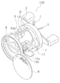
도 1은 본 발명의 제1 실시예가 채용된 양 베어링 릴의 사시도.
도 2는 양 베어링 릴의 사시도.
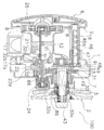
도 3은 양 베어링 릴의 단면도
도 4는 도 3의 드래그 기구의 단면 확대도.
도 5는 드래그 기구의 분해 사시도.
도 6은 구동축의 수나사부 외주 측의 단면 모식도.
도 7은 본 발명의 제2 실시예가 채용된 스피닝 릴의 측면도.
도 8은 스피닝 릴의 단면도.
도 9는 도 8의 스풀 부분의 단면 확대도.
도 10은 도 9의 드래그 손잡이 부분의 단면 확대도.
도 11은 스풀축의 수나사부 외주 측의 단면 모식도.
도 12는 제2 실시예의 드래그 기구를 포함하는 분해 사시도.1 is a perspective view of a double-bearing reel in which a first embodiment of the present invention is employed;
2 is a perspective view of a dual bearing reel;
Figure 3 is a cross-
Fig. 4 is an enlarged cross-sectional view of the drag mechanism of Fig. 3; Fig.
5 is an exploded perspective view of the drag mechanism;
6 is a schematic sectional view of the outer periphery of the male screw portion of the drive shaft.
7 is a side view of a spinning reel in which a second embodiment of the present invention is employed;
8 is a cross-sectional view of a spinning reel.
9 is a cross-sectional enlarged view of the spool portion of Fig.
10 is an enlarged cross-sectional view of the drag handle portion of Fig.
11 is a schematic sectional view of the outer peripheral side of the male thread portion of the spool shaft.
12 is an exploded perspective view including the drag mechanism of the second embodiment;
<제1 실시예>≪
도 1 및 도 2에 도시하는 바와 같이, 본 발명의 제1 실시예가 채용된 양 베어링 릴(100)은, 릴 본체(1)와, 릴 본체(1)의 측방(側方)에 배치된 스풀 회전용 핸들(2)과, 스풀(12)과, 스타 드래그(3)(제2 부재 및 조작 부재의 일례)를 가지는 스타 드래그형의 드래그 기구(23)(도 2 참조)를 구비한다.1 and 2, a double-bearing
도 2에 도시하는 바와 같이, 릴 본체(1)는, 프레임(5)과, 프레임(5)의 양 측방에 장착된 제1 측 커버(6) 및 제2 측 커버(7)를 가진다. 프레임(5)은, 소정의 간격을 두고 서로 대향하도록 배치된 제1 측판(8) 및 제2 측판(9)과, 제1 측판(8) 및 제2 측판(9)을 연결하는 전(前) 연결부(10a) 및 하(下) 연결부(10b)를 가진다. 하 연결부(10b)에는, 낚싯대 장착용의 장대 장착 다리부(10c)가 일체 형성된다.2, the
제1 측 커버(6)는, 스풀축 방향 외방(外方)으로부터 보아 원형(圓形)이고, 제2 측 커버(7)는, 2개의 교차하는 외주원(外周圓)으로 구성된 표주박형이다. 제1 측 커버(6)는, 도 1에 도시하는 바와 같이, 스풀(12)의 착탈(着脫)을 가능하게 하기 위하여 제1 측판(8)에 요동(搖動) 가능하게 장착되고, 프레임(5)에 대하여 개폐(開閉) 가능하다. 제2 측 커버(7)는, 제2 측판(9)과 동일한 2개의 외주원이 교차하는 편심(偏心)한 원형의 측면(側面)을 가진다. 제2 측 커버(7)는, 예를 들어 3개의 나사에 의하여 제2 측판(9)에 고정된다.The
프레임(5) 내에는, 스풀(12)과, 서밍(thumbing)을 행하는 경우의 엄지 손가락을 대는 부분으로 되는 클러치 레버(clutch lever)(17)와, 스풀(12) 내에 균일하게 낚싯줄을 감기 위한 레벨 와인드(level wind) 기구(18)가 배치된다. 프레임(5)과 제2 측 커버(7)와의 사이에는, 회전 전달 기구(19)와, 클러치 기구(21)와, 클러치 제어 기구(22)와, 드래그 기구(23)와, 캐스팅 컨트롤(casting control) 기구(24)가 배치된다. 또한, 프레임(5)과 제1 측 커버(6)와의 사이에는, 캐스팅 시의 백래시(backlash)를 억제하기 위한 원심(遠心) 브레이크 기구(25)가 배치된다.In the frame 5, a
회전 전달 기구(19)는, 핸들(2)로부터의 회전력을 스풀(12) 및 레벨 와인드 기구(18)에 전한다. 클러치 기구(21)는, 회전 전달 기구(19)의 도중에 설치되고, 구동축(30)과 스풀(12)을 연결·차단한다. 클러치 제어 기구(22)는, 클러치 레버(17)의 조작에 따라 클러치 기구(21)의 연결·연결 해제를 제어한다. 드래그 기구(23)는, 스타 드래그(3)의 조임량에 따라 스풀(12)의 줄 방출 방향의 회전을 제동한다. 캐스팅 컨트롤 기구(24)는, 스풀(12)의 회전 시의 저항력을 조정한다.The
스풀(12)은, 그 중심을 관통하는 스풀축(20)에 고정된다. 스풀축(20)은 베어링에 의하여 릴 본체(1)에 회전 가능하게 지지된다.The
클러치 레버(17)는, 도 3에 도시하는 바와 같이, 제1 측판(8) 및 제2 측판(9) 간의 후부(後部)에서 스풀(12) 후방(後方)에 배치된다. 클러치 레버(17)는 제1 측판(8) 및 제2 측판(9) 사이에서 상하(上下) 방향으로 슬라이드한다. 클러치 레버(17)의 핸들 장착 측에는, 계합(係合, 걸어 맞추는 것)축(17a)이 제2 측판(9)을 관통하여 일체 형성된다. 이 계합축(17a)은 클러치 제어 기구(22)에 계합한다.The
레벨 와인드 기구(18)는, 도 3에 도시하는 바와 같이, 스풀(12)의 전방(前方)에서 제1 측판(8) 및 제2 측판(9) 사이에 배치되고, 외주면(外周面)에 교차하는 나선상(螺旋狀) 홈(46a)이 형성된 트래버스 캠(traverse cam)축(46)과, 트래버스 캠축(46)에 의하여 스풀축 방향으로 왕복 이동하는 낚싯줄 안내부(47)를 가진다.The level wind mechanism 18 is disposed between the
회전 전달 기구(19)는, 구동축(30)(제1 부재의 일례)과, 구동축(30)에 고정된 구동 기어(31)와, 구동 기어(31)에 맞물리는 통상(筒狀)의 피니언 기어(pinion gear)(32)와, 트래버스 캠축(46)의 도 3 우단(右端)에 회전 불가능하게 장착된 기어 부재(48)와, 구동축(30)의 기단부(基端部)에 회전 불가능하게 장착된 기어 부재(49)를 가진다.The
구동축(30)은, 예를 들어, 스테인리스 합금제의 금속제의 축 부재다. 구동축(30)에는, 도 4 및 도 5에 도시하는 바와 같이, 기단 측으로부터 선단 측을 향하여 축지(軸支, 축으로 회전 가능하게 지지하는 것)부(30a), 제1 계지(係止, 서로 걸려 고정되는 것)부(30b), 테두리부(30c), 제2 계지부(30d), 제3 계지부(30e), 제1 수나사부(30f), 제2 수나사부(30g), 및 제4 계지부(30h)가 각각 형성된다. 축지부(30a)에는 베어링(28)이 장착된다. 제1 계지부(30b)는 축지부(30a)보다 대경(大徑)이고, 서로 평행한 2조(組)의 모따기부로 구성된다. 테두리부(30c)는 제1 계지부(30b)보다 대경이다. 제2 계지부(30d)는, 테두리부(30c)보다 소경(小徑)이고, 서로 평행한 2조의 모따기부로 구성된다. 제3 계지부(30e)는, 제2 계지부(30d)보다 소경이고, 서로 평행한 1조의 모따기부에 의하여 구성된다. 제1 수나사부(30f)는, 제3 계지부(30e)의 선단(先端) 측에 제3 계지부(30e)를 제외하는 외주면에 형성된다. 제2 수나사부(30g)는, 구동축(30)의 선단부에 제1 수나사부(30f)보다 소경으로 형성된다. 제4 계지부(30h)는, 제2 수나사부(30g)가 형성된 구동축(30)의 외주면에 형성된다. 제4 계지부(30h)에 핸들(2)이 회전 불가능하게 장착되고, 제2 수나사부(30g)에 틀어넣어진 너트(43)에 의하여 핸들(2)이 구동축(30)에 고정된다.The
제1 수나사부(30f)의 표면에는, 도 6에 모식적으로 도시하는 바와 같이, 불소 수지 함유 무전해 니켈 도금 피막(90)이 형성된다. 덧붙여, 도 6에서는 나사의 형상을 생략하여 도시한다. 불소 수지 함유 무전해 니켈 도금 피막(90)은, 불소 수지의 미립자를 실질적으로 균일하게 니켈 도금 용액 내에 분산 공석시켜 형성된 복합 도금 피막이다. 불소 수지 함유 무전해 니켈 도금 피막(90)에 이용하는 불소 수지는, 폴리테트라플루오로에틸렌(PTFE), 폴리클로로트리플루오로에틸렌(PCTFE), 폴리불화 비닐리덴(PVDF), 폴리불화 비닐(PVF), 퍼플루오로알콕시 불소 수지(PFA), 불화 에틸렌·6불화 프로필렌 공중합체(FEP), 에틸렌·4불화 에틸렌 공중합체(ETFE), 및 에틸렌·클로로트리플루오로에틸렌 공중합체(ECTFE)로 이루어지는 군으로부터 선택된다. 바람직하게는, 불소 수지는, 폴리테트라플루오로에틸렌(PTFE)이다. 덧붙여, 도 6에서는, 도트(dot)에 의하여, 불소 수지를 모식적으로 도시한다. 불소 수지 함유 무전해 니켈 도금 피막(90)의 막 두께는, 예를 들어 2㎛로부터 20㎛의 범위이고, 바람직하게는, 5㎛로부터 15㎛의 범위이다. 불소 수지의 공석량은, 도금액 전체의 예를 들어 1.5로부터 10 중량 퍼센트이다.On the surface of the first
구동축(30)은, 릴 본체(1)에 회전 가능하게 장착되어 있고, 역전 방지 기구(66)를 구성하는 롤러형의 제1 원웨이(one way) 클러치(86) 및 멈춤쇠식의 제2 원웨이 클러치(87)에 의하여 줄 방출 방향의 회전(역전)이 금지된다. 또한, 구동축(30)은, 베어링(28) 및 제1 원웨이 클러치(86)에 의하여 제2 측 커버(7) 및 프레임(5)에 회전 가능하게 지지된다.The
제1 원웨이 클러치(86)는, 구동축(30)의 중간부에 배치되고, 릴 본체(1)의 제2 측 커버(7)와 구동축(30)과의 간극(間隙)에 장착된다. 제1 원웨이 클러치(86)는, 제2 측 커버(7)에 회전 불가능하게 장착된 외륜(外輪)(86a)과, 구동축(30)에 회전 가능하게 장착된 내륜(內輪)(86b)과, 외륜(86a)과 내륜(86b)과의 사이에 배치된 롤러(86c)를 가진다.The first one-way clutch 86 is disposed in a middle portion of the
제2 원웨이 클러치(87)는, 래칫 휠(ratchet wheel)(61)과, 릴 본체(1)의 제2 측판(9)의 외측면(外側面)에 요동 가능하게 장착된 래칫 멈춤쇠(67)(도 5 참조)를 가진다. 래칫 휠(61)은, 구동 기어(31)와 기어 부재(49)와의 사이에서 제2 계지부(30d)에 회전 불가능하게 장착된다. 래칫 휠(61)은, 테두리부(30c)에 접촉하여 배치되고, 테두리부(30c)에 의하여 기단 측으로의 이동이 규제된다. 래칫 휠(61)의 외주부에는, 대략 평행사변형상으로 돌출하여 형성된 래칫 톱니(61a)가 둘레 방향으로 간격을 두고 배치된다. 릴 본체(1)에 요동 가능하게 장착된 래칫 멈춤쇠(67)가 래칫 톱니(61a)에 맞물리는 것에 의하여, 구동축(30)의 줄 방출 방향의 회전이 금지된다. 제2 원웨이 클러치(87)는, 드래그 기구(23)의 마찰판으로서 기능한다.The second one-way clutch 87 includes a
구동 기어(31)는, 구동축(30)에 회전 가능하게 장착되어 있고, 구동축(30)과 드래그 기구(23)를 통하여 연결된다. 드래그 기구(23)는 구동 기어(31)의 줄 방출 방향의 회전을 제동하는 것에 의하여, 스풀(12)의 줄 방출 방향의 회전을 제동한다.The
피니언 기어(32)는, 도 3에 도시하는 바와 같이, 제2 측판(9)의 외방으로부터 내방(內方)으로 연장되고, 중심에 스풀축(20)이 관통하는 통상 부재이다. 피니언 기어(32)는, 스풀축(20)에 축 방향으로 이동 가능하게 장착된다. 피니언 기어(32)의 도 3 좌단부(左端部)에는 스풀축(20)을 직경 방향으로 관통하는 계합 핀(20b)에 맞물리는 맞물림 홈(32a)이 형성된다. 이 맞물림 홈(32a)과 스풀축(20)에 장착된 계합 핀(20b)에 의하여 클러치 기구(21)가 구성된다. 또한, 피니언 기어(32)의 중간부에는 잘록부(32b)가, 우단부에는 구동 기어(31)에 맞물리는 기어부(32c)가 각각 형성된다. 잘록부(32b)에 클러치 제어 기구(22)의 클러치 요크(clutch yoke)(22a)가 계합한다.3, the
기어 부재(49)는, 구동축(30)의 기단부에 형성된 제1 계지부(30b)에 회전 불가능하게 장착되고, 테두리부(30c)에 기단부 측으로부터 당접(當接, 부딪는 상태로 접하는 것)한다. 트래버스 캠축(46)에 장착된 기어 부재(48)는, 구동축(30)에 장착된 기어 부재(49)에 맞물려 있다. 이와 같은 구성에 의하여, 레벨 와인드 기구(18)의 트래버스 캠축(46)은, 구동축(30)의 줄 감기 방향의 회전에 연동하여 회전한다.The
드래그 기구(23)는, 설정된 드래그력까지 구동축(30)과 구동 기어(31)를 연동 회전시켜 스풀(12)의 줄 방출 방향의 회전을 제동하는 기구이다. 드래그력은, 스타 드래그(3)의 조임 상태에 의하여 조절된다. 드래그 기구(23)는, 도 4 및 도 5에 도시하는 바와 같이, 스타 드래그(3)와, 구동축(30)과, 마찰 기구(4)와, 구동축(30)에 형성된 전술한 불소 수지 함유 무전해 니켈 도금 피막(90)(도 6 참조)을 구비한다. 또한, 드래그 기구(23)는, 발음 기구(65)와, 전술한 역전 방지 기구(66)를 구비한다.The
스타 드래그(3)는, 도 3에 도시하는 바와 같이, 방사상(放射狀)으로 배치된 복수의 조작부(3a)를 가지는 본체부(3b)와, 본체부(3b) 내에 일체 회전 가능하게 또한 축 방향 이동 가능하게 배치된 너트 부재(3c)를 가진다. 너트 부재(3c)는, 제1 수나사부(30f)에 나합하는 암나사부(3d)를 가진다. 스타 드래그(3)는, 그것보다 기단 측에서 구동축(30)에 장착된 마찰 기구(4)를 압압하여 소정의 드래그력을 조정하기 위한 조작 부재이다. 스타 드래그(3)와 제1 원웨이 클러치(86)와의 사이에는 4매의 접시 용수철(88)이 장착된다. 접시 용수철(88)은, 스타 드래그(3)의 조임력을 후술하는 드래그판(62)에 완만하게 전하기 위하여 설치되어 있다. 접시 용수철(88)은, 스타 드래그(3)의 너트 부재(3c)와 제1 원웨이 클러치(86)의 내륜(86b)과의 사이에 배치된다.3, the
스타 드래그(3)는, 그 조임 상태를 조절하는 것에 의하여, 구동축(30)을 제2 측 커버(7)에 장착된 제1 원웨이 클러치(86)의 내륜(86b)을, 접시 용수철(88)(도 3 참조)을 통하여 축 방향으로 이동시킬 수 있다. 즉, 스타 드래그(3)의 회동에 의하여, 접시 용수철(88)의 압압력이 조정된다. 이것에 의하여, 스타 드래그(3)에 의하여 드래그력을 미세하게 조정할 수 있다.The
마찰 기구(4)는, 구동축(30)에 일체 회전 가능하게 계합하는 드래그판(62)(마찰판의 일례)과, 래칫 휠(61)(마찰판의 일례)을 가진다. 드래그판(62)은, 제1 드래그 와셔(washer)(63a)를 통하여 구동 기어(31)(제2 마찰판의 일례)에 핸들(2) 측으로부터 접촉하는 원판 부재이다. 드래그판(62)은, 제3 계지부(30e)에 구동축(30)과 일체 회전 가능하게 장착된다. 드래그판(62)은, 래칫 휠(61)로 구동 기어(31)를 협지(挾持)한다. 또한, 드래그판(62)은, 제1 원웨이 클러치(86)의 내륜(86b)과 회전 불가능하게 연결되고 또한 당접한다. 이 결과, 제1 원웨이 클러치(86)의 내륜(86b)은, 구동축(30)에 대하여 일체 회전 가능한 것과 함께, 드래그판(62)에 스타 드래그(3)의 압압력을 전달한다. 드래그판(62)의 중심부에는, 내륜(86b)에 일체 회전 가능하게 계합하는 것과 함께, 구동축(30)의 제3 계지부(30e)에 일체 회전 가능하게 계합하는 계합 구멍(62a)이 형성된다. 구동 기어(31)는, 제2 드래그 와셔(63b)를 통하여 래칫 휠(61)에 접촉한다.The friction mechanism 4 has a drag plate 62 (an example of a friction plate) and a ratchet wheel 61 (an example of a friction plate) which are integrally rotatably engaged with the
제2 드래그 와셔(63b)는, 래칫 휠(61)과 구동 기어(31)와의 사이에 배치된 링상(狀)의 마찰 디스크이다. 제2 드래그 와셔(63b)의 내주(內周) 측에는, 링 부재(64)가 배치된다. 링 부재(64)는, 구동축(30)에 대하여 회전 가능하다. 또한, 링 부재(64)는, 구동 기어(31) 측에 계지 핀(64a)을 가진다. 계지 핀(64a)은, 구동 기어(31)의 측면에 관통하여 형성된 한 쌍의 계지 구멍(31a, 31b)의 어느 한쪽에 계합한다. 이 결과, 링 부재(64)는, 구동 기어(31)에 연동하여 회전한다. 링 부재(64)의 두께는, 제2 드래그 와셔(63b)의 두께보다 얇다. 이 때문에, 스타 드래그(3)에 의하여 드래그판(62)이 압압되어 구동 기어(31)가 드래그판(62)과 래칫 휠(61)에 의하여 협지되어도, 링 부재(64)에 압압력은 작용하지 않고, 회전 가능하다.The
발음 기구(65)는, 기어 부재(49)에 구동축 방향으로 진퇴 가능하게 장착된 타격 핀(70)과, 링 부재(64)의 핸들 측과 반대쪽의 측면에 둘레 방향으로 간격을 두고 형성된 다수의 음출(音出) 오목부(71)와, 타격 핀(70)을 링 부재(64)를 향하게 하여 압박하는 코일 용수철(72)을 가진다. 타격 핀(70)은, 선단에 음출 오목부(71)에 계합하는 머리부를 가진다. 타격 핀(70) 및 코일 용수철(72)은, 기어 부재(49)의 핸들 측의 측면으로 돌출하여 형성된 원통부(圓筒部)(49a)에 수납된다. 원통부(49a)는, 래칫 휠(61)의 중심 구멍의 근방에 형성된 관통 구멍(61b)에 삽입 가능한 크기이고, 링 부재(64) 측에 노출한다. 다수의 음출 오목부(71)는, 링 부재(64)의 타격 핀(70)에 대향 가능한 측면에 둘레 방향으로 간격을 두고 형성된다. 이와 같은 구성의 발음 기구(65)에서는, 드래그의 작동에 의하여 구동축(30)과 구동 기어(31)가 상대 회전하면, 구동축(30)에 대하여 회전 불가능한 타격 핀(70)이 구동 기어(31)와 함께 회전하는 링 부재(64)에 형성된 음출 오목부(71)에 대하여 충돌을 반복하여 발음한다.The sounding
다음으로, 이 양 베어링 릴의 동작을 설명한다.Next, the operation of the double-bearing reel will be described.
낚싯줄을 감을 때에는, 핸들(2)을 줄 감기 방향으로 돌린다. 핸들(2)의 회전은 구동축(30)으로부터 드래그 기구(23)를 통하여 구동축(30)에 연동하는 구동 기어(31) 및 피니언 기어(32)에 전달된다. 피니언 기어(32)의 회전은, 클러치 기구(21)에 의하여 피니언 기어(32)와 감합(嵌合)하는 스풀축(20)에 전달되고, 스풀(12)이 회전하여 낚싯줄을 감는다. 이 구동축(30)의 회전은, 기어 부재(49) 및 기어 부재(48)를 통하여 트래버스 캠축(46)에도 전달되고, 트래버스 캠축(46)의 회전에 의하여 낚싯줄 안내부(47)가 스풀축(20)을 따라 왕복 운동을 행한다. 이 왕복 운동에 의하여, 스풀(12)에 낚싯줄이 대략 균일하게 감긴다.When winding the fishing line, turn the
한편, 낚싯줄을 방출할 때에는, 클러치 레버(17)를 조작하여 클러치 제어 기구(22)에 의하여 클러치 기구(21)를 이탈 상태로 한다. 이것에 의하여, 스풀축(20)과 피니언 기어(32)와의 감합이 해제되고, 낚싯줄의 방출에 의하여 스풀(12)이 회전하여도 회전 전달 기구(19) 및 구동축(30)에는 그 회전은 전달되지 않는다.On the other hand, when releasing the fishing line, the
다음으로, 드래그 기구(23)의 동작에 관하여 설명한다.Next, the operation of the
물고기를 낚아 올릴 때에는, 낚싯줄에 텐션이 걸린다. 이것에 의하여, 스풀(12)에는 줄 방출 방향으로 회전하려고 하는 토크(torque)가 작용한다. 그러나 스풀(12)에 작용하는 드래그력이 설정된 드래그력보다도 작은 동안은, 스타 드래그(3)의 조임에 의하여 압축한 접시 용수철(88)에 의하여 구동 기어(31)가 제1 드래그 와셔(63a)를 통하여 래칫 휠(61) 및 제2 드래그판(62)에 협지되어 있고, 구동 기어(31)와 구동축(30)이 상대 회전 불가능하다. 그리고 구동축(30)은 역전 방지 기구(66)에 의하여 줄 방출 방향으로 회전하지 않도록 멈춰 있기 때문에, 구동 기어(31)와 연동하는 스풀(12)도 줄 방출 방향으로 회전하지 않는다. 덧붙여, 여기에서는 래칫 휠(61)과 구동 기어(31) 및 드래그판(62)과 구동 기어(31)와의 사이에 각각 제2 드래그 와셔(63b) 및 제1 드래그 와셔(63a)가 삽입되기 때문에, 작은 접시 용수철(88)의 압압력으로 래칫 휠(61) 및 드래그판(62)과 구동 기어(31)와의 사이에서 전달 가능한 토크를 크게 할 수 있다.Tension is applied to the fishing line when fishing. As a result, a torque is applied to the
낚싯줄에 걸리는 텐션이 높아지고 스풀(12)에 걸리는 토크가 커지면, 래칫 휠(61) 및 드래그판(62)과 구동 기어(31)와의 제2 드래그 와셔(63b) 및 제1 드래그 와셔(63a)를 통한 압접(壓接) 부분에서 슬립(slip)이 발생한다. 이것에 의하여, 구동축(30)의 회전을 멈추고 있어도 동마찰(動摩擦)의 저항을 받으면서 구동 기어(31)가 줄 방출 방향으로 회전하고, 스풀(12)도 줄 방출 방향으로 회전한다. 이와 같이, 스풀(12)에 작용하는 토크가 소정의 값을 넘으면, 바꾸어 말하면 낚싯줄에 과대(過大)한 장력이 걸리면, 드래그 기구(23)가 작동하여 스풀(12)이 줄 방출 방향으로 회전하고, 낚싯줄을 과대한 장력으로부터 보호한다.The
물고기를 낚아 올릴 때에 있어서 상기와 같이 스풀(12)이 줄 방출 방향으로 회전할 때에, 드래그 기구(23)의 발음 기구(65)가 음을 발생한다. 구동축(30)과 구동 기어(31)가 상대 회전하면, 구동 기어(31)에 연동하여 회전하는 링 부재(64)에 형성된 음출 오목부(71)와, 구동축(30)에 대하여 상대 회전 불가능한 기어 부재(49)에 연동하여 회전하는 타격 핀(70)이 간섭하여 클릭음을 발생한다. 이 클릭음은, 등간격(等間隔)으로 배치된 음출 오목부(71)에 코일 용수철(72)에 의하여 압박된 타격 핀(70)의 머리부가 간헐적으로 당접하는 것에 의하여 발생하기 때문에 리드미컬(rhythmical)한 음이다. 이 음 발생 시에는, 링 부재(64)는, 제2 드래그 와셔(63b)에 대하여 박육(薄肉)이기 때문에, 또한, 계지 핀(64a)과 계지 구멍(31a)과의 간극에 의하여, 직경 방향에 대해서도, 축 방향에 대해서도, 어느 정도 덜거거림을 가진 상태로 배치된다. 이와 같이, 링 부재(64)가 다른 부재에 의하여 꽉 눌려져 있지 않기 때문에, 발생하는 음이 잘 울리고, 음량도 크다.When the fish is pulled up, when the
또, 지깅을 행하는 경우에는, 스타 드래그(3)를 돌려 빈번하게 드래그력을 조정한다. 이때, 너트 부재(3c)가 제1 수나사부(30f)에 대하여 회동하여 너트 부재(3c)가 구동축(30)의 축 방향으로 이동한다. 예를 들어, 스타 드래그(3)를 도 2의 시계 방향으로 회전시키면, 너트 부재(3c)가 제1 원웨이 클러치(86)에 접근하는 방향으로 이동하고, 접시 용수철(88)을 압압하여 드래그력이 커진다. 이때, 설정된 드래그력이 큰 경우에 스타 드래그(3)가 돌기 어려워지는 일이 있다. 그러나 제1 실시예에서는, 제1 수나사부(30f)의 표면에 불소 수지 함유 무전해 니켈 도금 피막(90)이 형성되어 너트 부재(3c)의 접동 저항이 작아지고, 너트 부재(3c)가 부드럽게 회전한다. 이것에 의하여, 드래그력이 커져도 가벼운 조작력으로 스타 드래그(3)를 조작할 수 있게 된다. 게다가, 스타 드래그(3)의 조작 중에 있어서의 삐걱거리는 음이 작아져, 조작 필링이 향상한다.In addition, when jigging is performed, the star drag (3) is turned frequently to adjust the drag force. At this time, the
<제2 실시예>≪
제2 실시예와 관련되는 드래그 기구가 채용되는 낚시용 릴은, 양 베어링 릴은 아니고 스피닝 릴이다.The fishing reel in which the drag mechanism according to the second embodiment is employed is a spinning reel rather than a double-bearing reel.
<전체 구성><Overall configuration>
도 7 및 도 8에 있어서, 본 발명의 제2 실시예를 채용한 스피닝 릴(200)은, 핸들(101)을 회전 가능하게 지지하는 릴 본체(102)와, 로터(103)와, 스풀(104)과, 드래그 기구(160)(도 2 참조)를 구비하고 있다. 로터(103)는, 스풀(104)에 낚싯줄을 감는 것이고, 릴 본체(102)의 전부(前部)에 회전 가능하게 지지된다. 스풀(104)은, 외주면에 낚싯줄을 감는 것이고, 로터(103)의 전부에 전후(前後) 이동 가능하게 배치된다. 덧붙여, 핸들(101)은, 도 7에 도시하는 릴 본체(102)의 좌측과, 릴 본체(102)의 우측의 어느 쪽에도 장착 가능하다.7 and 8, a spinning reel 200 employing a second embodiment of the present invention includes a
핸들(101)은, 도 7에 도시하는 바와 같이, 핸들축(110)의 선단에 장착되는 핸들 암(108)과, 핸들 암(108)의 선단에 장착된 핸들 손잡이(109)를 구비하고 있다.7, the
릴 본체(102)는, 도 7 및 도 8에 도시하는 바와 같이, 개구(開口)(102d)를 가진다, 예를 들어 알루미늄 합금제의 릴 보디(102a)와, 개구(102d)를 막도록 릴 보디(102a)에 착탈 가능하게 장착된, 예를 들어 알루미늄 합금제의 덮개 부재(102b)(도 7 참조)와, 릴 보디(102a)로부터 비스듬히 상전방(上前方)으로 연장되는 장대 취부(取付) 다리(102c)를 가진다. 릴 보디(102a)는, 내부(內部)에 공간을 가지고 있고, 그 공간 내에는, 로터(103)를 핸들(101)의 회전에 연동하여 회전시키는 로터 구동 기구(105)와, 스풀(104)을 전후로 이동시켜 낚싯줄을 균일하게 감기 위한 오실레이팅(oscillating) 기구(106)가 설치되어 있다.The
로터 구동 기구(105)는, 도 8에 도시하는 바와 같이, 핸들(101)의 핸들축(110)이 고정된 구동 기어축(111a)과 함께 회전하는 구동 기어(111)와, 이 구동 기어(111)에 맞물리는 피니언 기어(112)를 가진다. 피니언 기어(112)는 통상으로 형성되어 있고, 그 전부(112a)는 로터(103)의 중심부를 관통하고 있으며, 너트(113)에 의하여 로터(103)와 고정된다. 피니언 기어(112)는, 그 축 방향의 중간부와 후단부(後端部)가, 릴 보디(102a)에 간격을 두고 장착된 베어링(114a, 114b)에 의하여 릴 보디(102a)에 회전 가능하게 지지된다.8, the
오실레이팅 기구(106)는, 스풀(104)의 중심부에 드래그 기구(160)를 통하여 연결된 스풀축(115)을 전후 방향으로 이동시켜 스풀(104)을 동(同) 방향으로 이동시키기 위한 기구이다. 오실레이팅 기구(106)는, 스풀축(115)의 하방(下方)에 평행으로 배치된 트래버스 캠축(121)과, 트래버스 캠축(121)을 따라 전후 방향으로 이동하는 슬라이더(122)와, 트래버스 캠축(121)의 선단에 고정된 중간 기어(123)를 가진다. 슬라이더(122)에는 스풀축(115)의 후단이 회전 불가능하게 고정된다. 중간 기어(123)는, 피니언 기어(112)에 직접적으로 또는 도시하지 않는 감속 기구를 통하여 간접적으로 맞물려 있다.The
스풀축(115)(제1 부재의 일례)은, 피니언 기어(112)의 중심부를 관통하여 배치된다. 스풀축(115)은, 피니언 기어(112)의 내부를 오실레이팅 기구(106)에 의하여 전후로 왕복 이동한다. 스풀축(115)은, 중간부가 너트(113) 내에 장착된 베어링(116)에 의하여, 후부가 피니언 기어(112)의 후부 내주면에 의하여, 회전 가능하게 또한 축 방향 이동 가능하게 지지된다. 스풀축(115)이 피니언 기어(112)와 상대 회전하면서 전후 이동할 때에, 피니언 기어(112)에 스풀축(115)이 달라붙는 것을 방지하기 위하여, 스풀축(115)의 표면에는, 무전해 니켈 도금이 입혀진다. 도 9 및 도 10에 도시하는 바와 같이, 스풀축(115)의 선단에는, 서로 평행한 면으로 구성된 회전 멈춤을 위한 계지면(115a)과, 드래그 조정용의 수나사부(115b)가 형성된다.The spool shaft 115 (an example of the first member) is disposed so as to pass through the center portion of the
수나사부(115b)의 표면에는, 도 11에 모식적으로 도시하는 바와 같이, 불소 수지 함유 무전해 니켈 도금 피막(190)이 형성된다. 제1 실시예에서는, 불소 수지 함유 니켈 도금 피막으로서, 불소 수지의 미립자를 니켈 도금액 중에 분산 공석시킨 복합 도금 피막이었다. 그러나 제2 실시예에서는, 불소 수지 함유 무전해 니켈 도금 피막(190)은, 입자상으로 석출시킨 니켈-인(Ni-P)의 다공질 피막(192)에 불소 수지(194)를 열처리에 의하여 복합화시킨 복합 도금 피막이다. 이 경우에는, 코스트는 증가하지만, 복합 도금 피막의 경도가 높아진다.On the surface of the
불소 수지 함유 무전해 니켈 도금 피막(190)에 이용하는 불소 수지(194)는, 제1 실시예와 마찬가지로, 폴리테트라플루오로에틸렌(PTFE), 폴리클로로트리플루오로에틸렌(PCTFE), 폴리불화 비닐리덴(PVDF), 폴리불화 비닐(PVF), 퍼플루오로알콕시 불소 수지(PFA), 불화 에틸렌·6불화 프로필렌 공중합체(FEP), 에틸렌·4불화 에틸렌 공중합체(ETFE), 및 에틸렌·클로로트리플루오로에틸렌 공중합체(ECTFE)로 이루어지는 군으로부터 선택된다. 바람직하게는, 불소 수지(194)는 폴리테트라플루오로에틸렌(PTFE)이다. 불소 수지 함유 무전해 니켈 도금 피막(190)의 막 두께는, 예를 들어 5㎛로부터 20㎛의 범위이고, 바람직하게는, 8㎛로부터 15㎛의 범위이다. 불소 수지(194)의 사용량은, 도금 전체의 예를 들어 1.5로부터 10 중량 퍼센트이다.The
로터(103)는, 도 8에 도시하는 바와 같이, 통상의 연결부(130)와, 연결부(130)의 측방에 서로 대향하여 설치된 제1 로터 암(131) 및 제2 로터 암(132)을 가지는 로터 본체(133)와, 로터 본체(133)에 요동 가능하게 장착된 베일 암(134)을 가진다. 로터 본체(133)는, 예를 들어 알루미늄 합금제이고 일체 성형된다.8, the
연결부(130)의 전부에는 전벽(前壁)(130a)이 형성되어 있고, 전벽(130a)의 중앙부에는 보스부(130b)가 형성된다. 보스부(130b)의 중심부에는 관통 구멍(130c)이 형성되어 있고, 이 관통 구멍(130c)을 피니언 기어(112)의 전부(112a) 및 스풀축(115)이 관통한다. 전벽(130a)의 전부에 너트(113)가 배치된다.A front wall 130a is formed at the front of the
제1 로터 암(131)은, 연결부(130)로부터 외방으로 볼록하게 만곡(彎曲)하여 전방으로 연장되어 있고, 연결부(130)의 둘레 방향으로 넓어져 만곡한다. 제2 로터 암(132)은, 연결부(130)로부터 외방으로 볼록하게 만곡하여 전방으로 연장되어 있고, 연결부(130)와의 접속부는 연결부(130)의 둘레 방향으로 넓어져 만곡한다. 덧붙여, 제2 로터 암(132)에는, 경량화를 위하여 개구(도시하지 않음)가 형성된다.The
도 8에 도시하는 바와 같이, 로터(103)의 연결부(130)의 내부에는 로터(103)의 역전을 금지하기 위한 역전 방지 기구(150)가 배치된다. 역전 방지 기구(150)는, 내륜이 유전(遊轉)하는 롤러형의 원웨이 클러치(151)를 가진다. 이 역전 방지 기구(150)는, 로터(103)의 줄 방출 방향의 역전을 상시(常時) 금지하고 있고, 역전을 허가하는 상태를 취할 일은 없다. 덧붙여, 역전 방지 기구를 역전 금지 상태와 역전 허가 상태로 전환할 수 있도록 구성하여도 무방하다.8, an
스풀(104)은, 도 8에 도시하는 바와 같이, 로터 본체(133)의 제1 로터 암(131)과 제2 로터 암(132)과의 사이에 배치되어 있고, 스풀축(115)의 선단에 장착된다. 스풀(104)은, 도 9에 도시하는 바와 같이, 외주에 낚싯줄이 감기는, 예를 들어 알루미늄 합금제의 줄 감기 몸통부(104a)와, 줄 감기 몸통부(104a)의 후부에 일체로 형성된 스커트부(104b)와, 줄 감기 몸통부(104a)의 전단(前端)에 일체 형성된 전(前) 플랜지부(104c)를 가진다. 스풀(104)의 내부에는, 설정된 드래그력이 스풀(104)에 작용하도록 스풀(104)을 제동하는 드래그 기구(160)가 수납된다.8, the
줄 감기 몸통부(104a)는, 원통상(圓筒狀)의 부재이고, 외주면은 스풀축(115)과 평행한 둘레면으로 구성된다. 줄 감기 몸통부(104a)는, 낚싯줄이 감기는 통상부(104d)와, 통상부(104d)의 내주면에 일체 형성된 원판상(圓板狀)의 지지 벽부(104e)와, 지지 벽부(104e)의 내주 측에 형성된 통상의 축지부(104f)를 가진다.The
스커트부(104b)는, 줄 감기 몸통부(104a)의 후방으로부터 직경 방향으로 연장되는 후(後) 플랜지부(104h)와, 후 플랜지부(104h)의 외주 측으로부터 후방으로 통상으로 연장되는 원통부(104i)를 가진다. 이 원통부(104i)의 내측(內側)에 로터(103)의 연결부(130)가 배치된다.The
전 플랜지부(104c)의 외주면에는, 낚싯줄을 줄 감기 몸통부(4a)로부터 부드럽게 방출하기 위한 금속제의 스풀 링(120)이 장착된다. 스풀 링(120)은, 앞쪽 끝으로 갈수록 넓어지는 경사면(120a)을 가진다. 스풀 링(120)은, 링 고정 부재(119)에 의하여 전 플랜지부(104c)에 고정된다. 링 고정 부재(119)는, 전 플랜지부(104c)로부터 전방으로 돌출하는 통상의 암나사부(104j)에 나합한다.A
줄 감기 몸통부(104a)의 내부에 있어서, 지지 벽부(104e)의 전방에는, 드래그 기구(160)를 수납하기 위한 드래그 수납 통부(152)가 일체 회전 가능하게 장착된다. 드래그 수납 통부(152)의 전방에는, 축지부(104f)로 스풀(104)을 스풀축(115)에 대하여 회전 가능하게 지지하기 위한 지지 통부(153)가 장착된다.Inside the
드래그 수납 통부(152)의 내부에는, 드래그 기구(160)의 후술하는 마찰 기구(162)가 수납된다. 드래그 수납 통부(152)는 스풀(104)과 일체 회전한다.A drag mechanism 160 (to be described later) of the
지지 통부(153)는 그 전방에서 스풀(104) 내부에 장착된 선재제(線材製)의 빠짐 방지 용수철(155)에 의하여 드래그 수납 통부(152)와 함께 빠짐 방지된다. 빠짐 방지 용수철(155)은, 줄 감기 몸통부(104a)의 전면(前面)과 링 고정 부재(119)의 후면(後面)과의 간극에서 스풀(104) 내에 보지(保持)된다.The support
스풀축(115)의 외주면에는, 스풀(104)을 스풀축(115)에 대하여 회전 가능하게 지지하기 위한 2개의 베어링(158a, 158b)이 장착되는 제1 지지부(156) 및 제2 지지부(157)가 끼워 넣어진다. 제1 지지부(156)는 스풀축(115)에 회전 가능하게 장착된다.A
제2 지지부(157)는, 도 12에 도시하는 바와 같이, 스풀축(115)의 앞쪽 부분에 형성된 계지면(115a)의 후부에 고정된다. 제2 지지부(157)는, 소경부(157a)와 대경부(157b)를 가지는 대소 2단의 단붙이 통상의 부재이다. 소경부(157a)에는, 베어링(158b)의 내륜이 장착된다. 베어링(158b)의 외륜은, 줄 감기 몸통부(104a)의 축지부(104f)에 장착된다. 대경부(157b)에는, 서로 평행한 면으로 구성된 제1 계지면(157c)과, 제1 계지면(157c)과 직교하는 제2 계지면(157d)이 형성된다. 이 제1 계지면(157c)을 관통하도록 배치된 멈춤 나사(159)에 의하여, 제2 지지부(157)는 스풀축(115)에 회전 불가능하게 고정된다. 멈춤 나사(159)는, 슬리팅(slitting)붙이의 중공(中空)의 세트 스크류(set screw)를 이용한 것이고, 제1 계지면(157c)을 통하여 계지면(115a)을 관통하는 나사 구멍에 틀어넣어진다.The
이와 같은 구성의 스풀(104)에서는, 줄 감기 몸통부(104a)의 지지 벽부(104e)의 전방에 지지 통부(153)를 설치하고, 지지 통부(153)에 베어링(158a)을 배치하였기 때문에, 축지부(104f)에 2개의 베어링을 나란히 놓는 종래의 구성에 비하여, 2개의 베어링(158a, 158b)의 축 방향의 간격을 넓게 할 수 있다. 이 때문에, 스풀(104)의 지지 간격이 넓어지고, 스풀(104)의 덜걱거림을 억제할 수 있다.In the
드래그 기구(160)는, 도 9 및 도 10에 도시하는 바와 같이, 스풀(104)의 줄 방출 방향으로의 회전을 제동하여 스풀(104)에 드래그력을 작용시키기 위한 기구이다. 드래그 기구(160)는, 드래그 손잡이(161)(제2 부재의 일례)와, 전술한 스풀축(115)과, 마찰 기구(162)와, 불소 수지 함유 무전해 니켈 도금 피막(190)과, 드래그 발음 기구(185)를 구비하고 있다. 드래그 손잡이(161)는, 드래그력을 손으로 조정하기 위한 조작 부재이다. 드래그 손잡이(161)에 의하여 마찰 기구(162)가 스풀(104) 측으로 압압되어 드래그력이 조정되는, 마찰 기구(162)는, 예를 들어 4매의 드래그 좌금(座金)(162a ~ 162d)(마찰판의 일례)을 가진다.9 and 10, the
드래그 손잡이(161)는, 도 10에 도시하는 바와 같이, 제1 손잡이 부재(166) 및 제1 손잡이 부재(166)에 대하여 상대 회전하는 제2 손잡이 부재(167)를 가지는 손잡이부(163)와, 제1 손잡이 부재(166)와 제2 손잡이 부재(167)와의 상대 회전에 의하여 발음하는 도시하지 않는 손잡이 발음 기구를 가진다.10, the drag handle 161 includes a
손잡이부(163)는, 제1 손잡이 부재(166) 및 제2 손잡이 부재(167)에 더하여 제1 손잡이 부재(166) 및 제2 손잡이 부재(167)를 축 방향 이동 불가능하게 또한 회전 가능하게 연결하는 연결 부재(174)를 더 가진다.The
제1 손잡이 부재(166)는, 링상의 테두리부(166a)와, 테두리부(166a)보다 소경의 원통부(166b)를 가지는 테두리붙이 통상의, 예를 들어 알루미늄 합금 등의 금속제의 부재이다. 제1 손잡이 부재(166)는, 스풀축(115)에 회전 불가능하게 또한 축 방향 이동 가능하게 설치되어 있다. 테두리부(166a)의 전단면에는, 손잡이 발음 기구를 구성하는 음출 원판(169)이 일체 회전 가능하게 설치되어 있다.The
음출 원판(169)은, 합성 수지제의 부재이고, 그 전면에는, 둘레 방향으로 간격을 두고 다수의 음출 오목부(169a)가 형성된다. 음출 원판(169)의 후면에는, 테두리부(166a)에 형성된 복수의 연결 구멍(166e)에 감합하는 복수의 연결 돌기(169b)가 형성된다. 이것에 의하여 음출 원판(169)은, 제1 손잡이 부재(166)에 대하여 회전 멈춤된다.The
원통부(166b)의 내주부에는, 스풀축(115)의 계지면(115a)에 회전 불가능하게 계합하는 장원상(長圓狀)의 계지 슬롯(166c)이 형성된다. 원통부(166b)의 후단면이 제1 지지부(156)를 통하여 마찰 기구(162)의 드래그 좌금(162a)에 당접한다.An
제2 손잡이 부재(167)는, 제1 손잡이 부재(166)에 대향하여 배치되고, 제1 손잡이 부재(166)와 상대 회동 가능하게 설치되어 있다. 제2 손잡이 부재(167)는, 스풀축(115)에 나합하는 것과 함께, 테두리부(166a)를 덮도록 제1 손잡이 부재(166)를 향하여 통상으로 돌출하는 부재이다. 제2 손잡이 부재(167)는, 손잡이체(171)와, 손잡이체(171)에 회전 불가능하게 또한 축 방향 이동 가능하게 장착되고, 스풀축(115)의 수나사부(115b)에 나합하는 암나사부(172a)를 가지는 너트 부재(172)와, 너트 부재(172)와 제1 손잡이 부재(166)와의 사이에 압축 상태로 배치된 코일 용수철로 이루어지는 용수철 부재(173)를 가진다.The
손잡이체(171)는, 원판부(175a)와, 원판부(175a)보다 소경의 통상의 돌출부(175b)를 가지는 합성 수지제의 손잡이 본체(175)와, 손잡이 본체(175)의 전면에 고정된 금속제의 원판상의 커버부(176)와, 커버부(176)의 전면에 직경 방향을 따라 고정된 금속제의 조작 손잡이(177)를 가진다.The
손잡이 본체(175)의 원판부(175a)의 배면(背面) 측으로부터는, 4개의 볼트 부재(180a ~ 180d)가 삽입되고, 커버부(176)를 관통하여 조작 손잡이(177)에 틀어넣어져 있다. 이것에 의하여, 커버부(176)와 조작 손잡이(177)가 손잡이 본체(175)에 고정된다.Four bolt members 180a to 180d are inserted from the rear surface side of the disk portion 175a of the
돌출부(175b)는, 제1 손잡이 부재(166)의 테두리부(166a)를 덮도록 제1 손잡이 부재(166)를 향하여 통상으로 돌출한다. 돌출부(175b)로 덮인 제1 손잡이 부재(166)의 테두리부(166a)는, 돌출부(175b)의 내주면에 장착된 연결 부재(174)에 의하여 빠짐 방지된다. 이것에 의하여, 제1 손잡이 부재(166)와 제2 손잡이 부재(167)가 상대 회전 가능하게 또한 축 방향 이동 불가능하게 연결된다. 손잡이 본체(175)의 내주부에는, 너트 부재(172)가 축 방향 이동 가능하게 또한 일체 회전 가능하게 수납되는 너트 수납부(175c)가 형성된다.The
커버부(176)는, 손잡이 본체(175)의 원판부(175a)의 전면 및 외주면의 일부를 덮도록 형성된다. 이 결과, 드래그 손잡이(161)의 기구 부분을 구성하는 합성 수지제의 손잡이 본체(175)는 스풀(104) 내에 가려져 외부에 노출하지 않게 된다. 커버부(176)의 전면은, 중심 부분을 향하여 서서히 두께가 얇아지도록 파여 있다. 조작 손잡이(177)는, 커버부(176)의 직경을 따라 배치되고, 전방으로 돌출한다.The
연결 부재(174)는, 탄성(彈性)을 가지는 금속 선재를 꺾어 구부려 형성된 부재이다. 연결 부재(174)는, 대략 정방형의 각(角)에 상당하는 4개의 각부를 가지는 C자 형상의 용수철 부재이다. 연결 부재(174)는, 돌출부(175b)의 내주면에 형성된 환상(環狀) 홈에 각부가 계지되는 것에 의하여 돌출부(175b)의 내주면에 장착된다. 연결 부재(174)는, 각부의 사이의 3개의 원호부(圓弧部)가 테두리부(166a)의 후면에 접촉하는 것에 의하여, 테두리부(166a)를 빠짐 방지한다.The connecting
너트 부재(172)는, 예를 들어 육각 너트이고, 스풀축(115)의 선단 외주면에 형성된 수나사부(115b)에 나합하고, 손잡이 본체(175)의 회동에 따라 용수철 부재(173)를 압축한다.The
손잡이 발음 기구는, 드래그 조작 시에 제2 손잡이 부재(167)와 제1 손잡이 부재(166)가 상대 회전하면, 음출 오목부(169a)와의 충돌을 반복하여 발음한다.When the
마찰 기구(162)의 드래그 좌금(162a)은, 도 9 및 도 12에 도시하는 바와 같이, 제1 손잡이 부재(166)에 제1 지지부(156)를 통하여 접촉하고, 또한 스풀축(115)에 대하여 회전 불가능한 금속제의 원판 부재이다. 드래그 좌금(162b)은, 스풀(104)에 대하여 일체 회전 가능한 금속제의 원판 부재이다. 드래그 좌금(162c)은, 드래그 좌금(162a)과 마찬가지로 스풀축(115)에 대하여 회전 불가능한 금속제의 원판 부재이다. 드래그 좌금(162d)은, 스풀(104) 및 스풀축(115)에 대하여 회전 가능한 예를 들어 펠트(felt)제 또는 그라파이트(graphite)제의 원판 부재이다. 드래그 좌금(162a, 162c)의 중심부에는, 스풀축(115)의 선단 측에 형성된 계지면(115a)에 계합하는 장원형의 계지 슬롯(162e)이 형성된다. 드래그 좌금(162b)의 외주면에는, 직경 방향 외방으로 돌출하는 복수(예를 들어 8개)의 귀부(162f)가 형성된다. 이 귀부(162f)는, 드래그 수납 통부(152)의 내주면에 둘레 방향으로 간격을 두고 배치되고, 축 방향을 따라 형성된 복수의 계지 오목부(152a)에 계지된다. 이것에 의하여, 드래그 좌금(162b)은, 스풀(104)에 대하여 일체 회전 가능하게 되어 있다.9 and 12, the
드래그 좌금(162a ~ 162d)은, 지지 통부(153)를 지지하는 제1 지지부(156)에 의하여 빠짐 방지된다. 따라서 지지 통부(153)의 전방에 배치된 빠짐 방지 용수철(155)을 떼어 내지 않으면 드래그 좌금(162a ~ 162d)은 착탈할 수 없다.The
드래그 발음 기구(185)는, 드래그의 작동에 의하여 스풀축(115)과 스풀(104)이 상대 회전하면 발음하는 기구이다. 드래그 발음 기구(185)는, 도 12에 도시하는 바와 같이, 스풀(104)의 후 플랜지부(104h)의 배면에 장착되고 스풀(104)과 일체 회전하는 제1 발음 부재(186)와, 제1 발음 부재(186)에 대하여 타격을 반복하고 제2 발음 부재(187)를 가진다.The dragging
제1 발음 부재(186)는, 단붙이 원통 형상이고, 내주면에 원호상(圓弧狀)의 다수의 음출 오목부(186a)가 형성된 금속제의 부재이다. 제1 발음 부재(186)의 후면에는 명판(名板)(188)이 배치되고, 명판(188)과 함께, 제1 발음 부재(186)는 후 플랜지부(104h)의 배면에 나사 멈춤된다.The first
제2 발음 부재(187)는, 음출 오목부(186a)를 향하여 진퇴하는 2개의 타격 핀(187a)과, 2개의 타격 핀(187a)을 음출 오목부(186a)를 향하여 압박하는 2개의 용수철 부재(187b)를 가진다. 타격 핀(187a)은, 제2 지지부(157)의 제2 계지면(157d)에 회전 불가능하게 계합하는 통상의 수납 부재(189)에 수납된다. 수납 부재(189)는, 타격 핀(187a)을 진퇴 가능하게 수납하는 2개의 수납 홈(189c)을 가지는 후육(厚肉) 원통상의 수납 본체부(189a)와, 수납 본체부(189a)에 나사 멈춤되어 수납 홈(189c)을 막는 것과 함께, 제2 계지면(157d)에 계합하는 원판상의 커버(189b)를 가진다. 수납 본체부(189a)의 2개의 수납 홈(189c)은, 수납 본체부(189a)의 외주면에 개구하고 있고, 개구 측의 2개의 수납 홈(189c)의 간격이 좁아지도록 형성된다. 커버(189b)의 내주면에는, 제2 계지면(157d)에 계합하는 계지 슬롯(189d)이 형성된다. 수납 부재(189)와, 스풀(104)의 지지 벽부(104e)와의 사이에는 와셔(201)가 배치된다.The second
커버(189b)의 후면에는, 제2 지지부(157)의 제1 계지면(157c)에 계합하는, 예를 들어 합성 수지제의 3매의 스풀 위치 조정 와셔(202)와, 스풀(104)의 후방으로의 이동을 규제하는 2매의 규제 와셔(203, 204)가 장착된다. 규제 와셔(203, 204)는, 스풀축(115)의 계지면(115a)에 계합하는 계지 슬롯(203a, 204a)이 내주부에 형성되어 있고, 스풀축(215)에 대하여 회전 불가능하다. 규제 와셔(204)는, 단붙이 와셔이고, 규제 와셔(203)와 실(seal) 부재(205)를 보지한다. 실 부재(205)의 외주부는, 제1 발음 부재(186)의 내주면에 접촉한다. 실 부재(205)는, 스풀(104)의 후면으로부터 마찰 기구(162)를 포함하는 스풀(104) 내부로의 액체의 유입을 방지하기 위하여 설치되어 있다.The rear surface of the
〔릴의 조작 및 동작〕[Reel operation and operation]
낚시를 행하기 전에 물고기의 크기나 종류에 맞추어 드래그력을 조정한다. 드래그력을 조정하려면, 드래그 손잡이(161)를 돌린다. 드래그 손잡이(161)를 예를 들어 시계 방향으로 돌리면, 스풀축(115)에 나합하는 너트 부재(172)에 의하여 용수철 부재(173)를 통하여 제1 손잡이 부재(166)가 마찰 기구(162) 측으로 압압된다. 이것에 의하여 드래그력이 커진다. 이때, 제1 손잡이 부재(166)와 제2 손잡이 부재(167)와의 상대 회전에 의하여 명확하고 경쾌한 클릭음이 발생한다.Adjust the drag force to match the size and type of fish before fishing. To adjust the drag force, turn the drag knob (161). The
캐스팅 시에는, 베일 암(134)을 줄 개방 자세로 반전(反轉)시킨다. 이것에 의하여 낚싯줄을 스풀(104)로부터 방출 가능하게 된다. 이 상태에서 낚싯대를 잡는 손의 집게 손가락으로 낚싯줄을 걸면서 낚싯대를 캐스팅한다. 그러면 낚싯줄은 채비의 무게에 의하여 힘차게 방출된다. 이 상태에서 핸들(101)을 줄 감기 방향으로 회전시키면, 로터 구동 기구(105)에 의하여 로터(103)가 줄 감기 방향으로 회전하고, 베일 암(134)이 베일 반전 기구(도시하지 않음)에 의하여 줄 감기 위치로 복귀하며, 낚싯줄이 베일 암(134)에 의하여 스풀(104)에 감긴다.At the time of casting, the
지깅을 행하는 경우, 줄 감기 시에 낚아 올리는 물고기에 따라 드래그력을 조정하지 않으면 안 되는 상황이 발생하는 일이 있다. 이 경우에서도, 스풀축(115)의 수나사부(115b)의 표면에 불소 수지 함유 무전해 니켈 도금 피막(190)이 형성되기 때문에, 드래그 손잡이(161)와의 접동 성능이 높아진다. 이 때문에, 드래그력이 커져도 가벼운 조작력으로 드래그 손잡이(161)를 조작할 수 있게 된다.When jigging is performed, there may be a situation where the drag force must be adjusted depending on the fish that is caught at the time of winding the line. Even in this case, since the electroless
<특징><Features>
상기 실시예는, 하기와 같이 표현 가능하다.The above embodiment can be expressed as follows.
(A) 낚시용 릴의 드래그 기구(23)(또는 160)는, 낚시용 릴의 줄 감기용의 스풀(12)(또는 104)의 줄 방출 방향의 회전을 제동하는 기구이다. 낚시용 릴의 드래그 기구(23)(또는 160)는, 제1 수나사부(30f)(또는 115b)를 가지는 구동축(30)(또는 스풀축(115))과, 스타 드래그(3)(또는 드래그 손잡이(161))와, 마찰 기구(4)(또는 162)와, 불소 수지 함유 무전해 니켈 도금 피막(90)(또는 190)을 구비한다. 스타 드래그(3)(또는 드래그 손잡이(161))는, 제1 수나사부(30f)(또는 115b)에 나합하는 암나사부(3d)(또는 172a)를 가진다. 마찰 기구(4)(또는 162)는, 스타 드래그(3)(또는 드래그 손잡이(161)) 및 구동축(30)(또는 스풀축(115))을 상대적으로 회동시키는 것에 의하여, 마찰력이 변화하고, 스풀(12)(또는 104)의 줄 방출 방향의 회전을 제동 가능한 기구이다. 불소 수지 함유 무전해 니켈 도금 피막(90)(또는 190)은, 적어도 제1 수나사부(30f)(또는 수나사부(115b)) 및 암나사부(3d)(또는 172a)의 어느 한쪽에 형성된다.(A) The drag mechanism 23 (or 160) of the fishing reel is a mechanism for braking the rotation of the spool 12 (or 104) for fishing line reeling in the fishing line reeling direction. The drag mechanism 23 (or 160) of the fishing reel has the drive shaft 30 (or the spool shaft 115) having the first
이 드래그 기구(23)(또는 160)에서는, 제1 부재인 구동축(30)(또는 스풀축(115)) 및 제2 부재인 스타 드래그(3)(또는 드래그 손잡이(161))의 일방을 조작 부재로서 타방의 부재와 상대 회동시키는 것에 의하여, 마찰 기구(4)(또는 162)의 마찰력이 변화하고, 드래그력을 조정할 수 있다. 이 구동축(30)(또는 스풀축(115))의 제1 수나사부(30f)(또는 115b) 및 스타 드래그(3)(또는 드래그 손잡이(161))의 암나사부(3d)(또는 172a)의 적어도 어느 일방에는, 불소 수지 함유 무전해 니켈 도금 피막(90)(또는 190)이 형성된다. 이 때문에, 불소 수지 함유 무전해 니켈 도금 피막(90)(또는 190)의 막 두께가 균일하게 되고, 상대 회동하는 제1 수나사부(30f)(또는 115b)와 암나사부(3d)(또는 172a)와의 사이의 접동 저항이 작아지고, 제1 수나사부(30f)(또는 115b)와 암나사부(3d)(또는 172a)와의 상대 회동이 부드럽게 된다. 이것에 의하여, 드래그력이 커져도 가벼운 조작력으로 조작 부재를 조작할 수 있게 된다. 게다가, 스타 드래그(3)(또는 드래그 손잡이(161))의 조작 중에 있어서의 삐걱거리는 음이 작아져, 조작 필링이 향상한다.In this drag mechanism 23 (or 160), one of the drive shaft 30 (or the spool shaft 115) as the first member and the star drag 3 (or the drag handle 161) as the second member is operated The frictional force of the friction mechanism 4 (or 162) is changed by rotating the member relative to the other member so that the drag force can be adjusted. Of the
(B) 낚시용 릴의 드래그 기구(23)(또는 160)에 있어서, 불소 수지는, 폴리테트라플루오로에틸렌(PTFE), 폴리클로로트리플루오로에틸렌(PCTFE), 폴리불화 비닐리덴(PVDF), 폴리불화 비닐(PVF), 퍼플루오로알콕시 불소 수지(PFA), 불화 에틸렌·6불화 프로필렌 공중합체(FEP), 에틸렌·4불화 에틸렌 공중합체(ETFE), 및 에틸렌·클로로트리플루오로에틸렌 공중합체(ECTFE)로 이루어지는 군으로부터 선택되어도 무방하다. 이 경우에는, 불소 수지 중에서도 특히 접동성이 높은 것을 선택할 수 있다.(B) In the drag mechanism 23 (or 160) of the fishing reel, the fluororesin may be at least one selected from the group consisting of polytetrafluoroethylene (PTFE), polychlorotrifluoroethylene (PCTFE), polyvinylidene fluoride (PVDF) (PTFE), fluorinated ethylene · hexafluoropropylene copolymer (FEP), ethylene · tetrafluoroethylene copolymer (ETFE), and ethylene · chlorotrifluoroethylene copolymer (ECTFE). In this case, among fluororesins, those having particularly high sliding properties can be selected.
(C) 낚시용 릴의 드래그 기구에 있어서, 낚시용 릴은, 핸들(2)의 회전에 의하여 스풀(12)이 회전하는 양 베어링 릴(100) 또는 편 베어링 릴이어도 무방하다. 제1 부재는 핸들(2)의 회전에 의하여 회전하는 구동축(30)이다. 제2 부재는, 구동축(30)에 나합하는 스타 드래그(3)이다. 마찰 기구(4)는, 구동축(30)에 배치되고, 스타 드래그(3)에 의하여 압압되는 적어도 1매의 드래그판(62)을 가진다. 이 경우에는, 구동축의 주위에 드래그판(62)이 배치된다. 드래그 기구(23)를 가지는 양 베어링 릴(100) 또는 편 베어링 릴에 있어서, 드래그력이 커져도 가벼운 조작력으로 스타 드래그(3)를 조작할 수 있게 된다.(C) In the drag mechanism of the fishing reel, the fishing reel may be a double-
(D) 양 베어링 릴의 드래그 기구(23)에 있어서, 구동축(30)의 줄 방출 방향의 회전을 금지하는 역전 방지 기구(66)를 더 구비하여도 무방하다. 이 경우에는 구동축(30)이 줄 방출 방향으로 회전하지 않기 때문에, 드래그판(62)을 적어도 구동축(30)에 일체 회전 가능하게 설치하는 것에 의하여, 스타 드래그형의 드래그 기구(23)를 구성할 수 있다.(D) Further, the
(E) 낚시용 릴의 드래그 기구(160)에 있어서, 낚시용 릴은, 스풀축(115)에 회전 가능하게 감는 스피닝 릴(200)이다. 제1 부재는 스풀(104)이 회전 가능하게 장착되는 스풀축(115)이다. 제2 부재는, 스풀축(115)에 나합하는 드래그 손잡이(161)이다. 마찰 기구(162)는, 스풀축(115)에 배치되고, 드래그 손잡이(161)에 의하여 압압되는 적어도 1매의 드래그 좌금(162a ~ 162d)을 포함한다. 이 경우에는, 스풀축(115)의 주위에 드래그 좌금(162a ~ 162d)이 배치되는 스피닝 릴에 있어서, 드래그력이 커져도 가벼운 조작력으로 드래그 손잡이(161)를 조작할 수 있게 된다.(E) In the
(F) 낚시용 릴의 드래그 기구(23)(또는 160)에 있어서, 불소 수지 함유 무전해 니켈 도금 피막(90)(또는 190)은, 제1 수나사부(30f)(또는 수나사부(115b))에 형성되어도 무방하다. 이 경우에는, 제1 수나사부(30f)(또는 수나사부(115b))에 불소 수지 함유 무전해 니켈 도금 피막(90)(또는 190)이 형성되기 때문에, 드래그력의 조정 위치에 따라 불소 수지 함유 무전해 니켈 도금 피막(90)(또는 190)과 암나사부(3d)(또는 172a)와의 접촉 위치가 변화한다. 또한, 이 때문에, 불소 수지 함유 무전해 니켈 도금 피막(90)(또는 190)의 장수명화를 도모할 수 있다.(Or F) In the drag mechanism 23 (or 160) of the fishing reel, the fluororesin-containing electroless nickel plating film 90 (or 190) has the first
(G) 낚시용 릴의 드래그 기구(23)에 있어서, 불소 수지 함유 무전해 니켈 도금 피막(90)은, 불소 수지의 미립자를 분산 공석시킨 복합 도금 피막이어도 무방하다. 이 경우에는, 코스트의 증가를 억제하여 불소 수지 함유 무전해 니켈 도금 피막(90)을 형성할 수 있다.(G) In the
(H) 낚시용 릴의 드래그 기구(160)에 있어서, 불소 수지 함유 무전해 니켈 도금 피막(190)은, 입자상으로 석출시킨 니켈-인(Ni-P)의 다공성 피막에 불소 수지를 열처리에 의하여 복합화시킨 복합 도금 피막이어도 무방하다. 이 경우에는, 복합 도금 피막의 형성 코스트가 비싸지지만, 복합 도금 피막의 경도가 높아진다.(H) In the
<다른 실시예><Other Embodiments>
이상, 본 발명의 일 실시예에 관하여 설명하였지만, 본 발명은 상기 실시예에 한정되는 것이 아니고, 발명의 요지를 일탈하지 않는 범위에서 여러 가지의 변경이 가능하다. 특히, 본 명세서에 쓰여진 복수의 실시예 및 변형예는 필요에 따라 임의로 조합 가능하다.While the present invention has been described in connection with the preferred embodiments thereof, it is to be understood that the invention is not limited to the disclosed exemplary embodiments. In particular, a plurality of embodiments and modifications written in this specification may be arbitrarily combined as needed.
(a) 제1 및 제2 실시예에서는, 드래그 기구로서, 양 베어링 릴의 스타 드래그 기구 및 스피닝 릴의 프런트 드래그(front drag) 기구를 예시하였지만, 본 발명의 드래그 기구는, 이것에 한정되지 않는다. 예를 들어, 스피닝 릴의 리어 드래그(rear drag) 기구, 양 베어링 릴의 레버 드래그 기구, 핸들이 스풀에 설치되는 편 베어링 릴의 드래그 기구에도 본 발명을 적용할 수 있다.(a) In the first and second embodiments, the star drag mechanism of the double-bearing reel and the front drag mechanism of the spinning reel are exemplified as the drag mechanism, but the drag mechanism of the present invention is not limited to this . For example, the present invention can be applied to a drag mechanism of a single-bearing reel in which a handle is attached to a spool, a lever drag mechanism of a double-bearing reel, and a rear drag mechanism of a spinning reel.
(b) 제1 및 제2 실시예에서는, 제1 부재인 구동축 또는 스풀축에 불소 수지 함유 무전해 니켈 도금 피막이 형성되지만, 본 발명은 이것에 한정되지 않는다. 예를 들어, 제1 부재인 스타 드래그 또는 드래그 손잡이에 설치되는 암나사부에 불소 수지 함유 무전해 니켈 도금 피막을 설치하여도 무방하다.(b) In the first and second embodiments, the electroless nickel plating film containing fluorine resin is formed on the drive shaft or the spool shaft as the first member, but the present invention is not limited to this. For example, a fluorine resin-containing electroless nickel plating film may be provided on the female screw portion provided on the first member, the star drag or the drag handle.
(c) 제1 및 제2 실시예에 의한 불소 수지를 분산 공석시킨 니켈 도금 피막에 대신하여, 불소 수지를 분산 공석시킨 니켈-인 도금 피막 또는 니켈-붕소 도금 피막이어도 무방하다. 단, 이 경우에는, 복합 도금 피막을 형성하는 코스트가 비싸진다.(c) A nickel-plated film or a nickel-boron plated film in which a fluororesin is dispersed in place may be used in place of the nickel-plated film obtained by dispersing the fluororesin of the first and second embodiments. However, in this case, the cost of forming the composite plating film becomes higher.
(d) 상기 실시예에서는, 불소 수지로서, 폴리테트라플루오로에틸렌(PTFE)을 예시하였지만, 본 발명은 이것에 한정되지 않는다. 불소 수지는, 폴리테트라플루오로에틸렌(PTFE), 폴리클로로트리플루오로에틸렌(PCTFE), 폴리불화 비닐리덴(PVDF), 폴리불화 비닐(PVF), 퍼플루오로알콕시 불소 수지(PFA), 불화 에틸렌·6불화 프로필렌 공중합체(FEP), 에틸렌·4불화 에틸렌 공중합체(ETFE), 및 에틸렌·클로로트리플루오로에틸렌 공중합체(ECTFE)로 이루어지는 군으로부터 선택되는 것이면 어떠한 것이어도 무방하다.(d) In the above embodiment, polytetrafluoroethylene (PTFE) is exemplified as the fluororesin, but the present invention is not limited thereto. The fluororesin may be at least one selected from the group consisting of polytetrafluoroethylene (PTFE), polychlorotrifluoroethylene (PCTFE), polyvinylidene fluoride (PVDF), polyvinyl fluoride (PVF), perfluoroalkoxy fluoropolymer (PFA) Any of those selected from the group consisting of propylene hexafluoropropylene copolymer (FEP), ethylene · tetrafluoroethylene copolymer (ETFE), and ethylene · chlorotrifluoroethylene copolymer (ECTFE) may be used.
(e) 제1 실시예 및 제2 실시예에서는, 모두 제1 부재인 구동축(30)(또는 스풀축(115))의 제1 수나사부(30f)(또는 수나사부(115b))에 불소 수지 함유 무전해 니켈 도금 피막(90)(또는 190)을 형성하였지만 본 발명은 이것에 한정되지 않는다. 제2 부재인 너트 부재(3c)(또는 172)의 암나사부(3d)(또는 172a)에 불소 수지 함유 무전해 니켈 도금 피막을 형성하여도 무방하다. 또한, 제1 수나사부(30f)(또는 수나사부(115b))와 암나사부(3d)(또는 172a)의 양방(兩方)에 불소 수지 함유 무전해 니켈 도금 피막을 형성하여도 무방하다. 나아가, 구동축(30)(또는 스풀축(115))의 전체에 불소 수지 함유 무전해 니켈 도금 피막을 형성하여도 무방하다.(e) In the first embodiment and the second embodiment, the first male threaded
2: 핸들
3: 스타 드래그
3c: 너트 부재
3d: 암나사부
4: 마찰 기구
12: 스풀
23: 드래그 기구
30: 구동축
30f: 제1 수나사부
31: 구동 기어
61: 래칫 휠
62: 드래그판
66: 역전 방지 기구
67: 래칫 멈춤쇠
90: 불소 수지 함유 무전해 니켈 도금 피막
100: 양 베어링 릴
101: 핸들
104: 스풀
115: 스풀축
115b: 수나사부
160: 드래그 기구
161: 드래그 손잡이
162a: 드래그 좌금
162b: 드래그 좌금
162c: 드래그 좌금
162d: 드래그 좌금
172: 너트 부재
172a: 암나사부
190: 불소 수지 함유 무전해 니켈 도금 피막
192: 다공질 피막
194: 불소 수지
200: 스피닝 릴2: Handle
3: Star Drag
3c: Nut member
3d: Female threads
4: Friction mechanism
12: spool
23: Drag mechanism
30: drive shaft
30f: first male thread
31: drive gear
61: ratchet wheel
62: Drag plate
66: Anti-reverse mechanism
67: ratchet detent
90: Electroless nickel plated film containing fluorine resin
100: Both bearing reel
101: Handle
104: spool
115: Spool shaft
115b:
160: Drag mechanism
161: Drag handle
162a: Drag balance
162b: Drag balance
162c: Drag balance
162d: Drag balance
172: Nut member
172a: female thread portion
190: Electroless nickel plated film containing fluorine resin
192: Porous film
194: Fluorine resin
200: spinning reel
Claims (8)
수나사부를 가지는 제1 부재와,
상기 수나사부에 나합(螺合)하는 암나사부를 가지는 제2 부재와,
상기 제1 부재 및 상기 제2 부재를 상대적으로 회동시키는 것에 의하여, 마찰력이 변화하고, 상기 스풀의 상기 줄 방출 방향의 회전을 제동 가능한 마찰 기구와,
적어도 상기 수나사부 및 상기 암나사부의 어느 한쪽에 형성된 불소 수지 함유 무전해 니켈 도금 피막
을 구비한 낚시용 릴의 드래그 기구.A fishing reel drag mechanism for braking rotation of a spool for fishing line rewinding of a fishing reel in a line releasing direction,
A first member having a male thread portion,
A second member having a female threaded portion engaged with the male threaded portion,
A friction mechanism that changes the frictional force by relatively rotating the first member and the second member and that is capable of braking the rotation of the spool in the line-
A fluororesin-containing electroless nickel plating film formed on at least one of the male screw portion and the female screw portion
And a drag mechanism for fishing the reel.
상기 불소 수지는, 폴리테트라플루오로에틸렌(PTFE), 폴리클로로트리플루오로에틸렌(PCTFE), 폴리불화 비닐리덴(PVDF), 폴리불화 비닐(PVF), 퍼플루오로알콕시 불소 수지(PFA), 불화 에틸렌·6불화 프로필렌 공중합체(FEP), 에틸렌·4불화 에틸렌 공중합체(ETFE), 및 에틸렌·클로로트리플루오로에틸렌 공중합체(ECTFE)로 이루어지는 군으로부터 선택되는, 낚시용 릴의 드래그 기구.The method according to claim 1,
The fluororesin may be at least one selected from the group consisting of polytetrafluoroethylene (PTFE), polychlorotrifluoroethylene (PCTFE), polyvinylidene fluoride (PVDF), polyvinyl fluoride (PVF), perfluoroalkoxy fluoropolymer Wherein the drag mechanism is selected from the group consisting of ethylene · hexafluoropropylene copolymer (FEP), ethylene · tetrafluoroethylene copolymer (ETFE), and ethylene · chlorotrifluoroethylene copolymer (ECTFE).
상기 낚시용 릴은, 핸들의 회전에 의하여 스풀이 회전하는 릴이고,
상기 제1 부재는, 상기 핸들의 회전에 의하여 회전하는 구동축이고,
상기 제2 부재는, 상기 구동축에 나합하는 조작 부재이고,
상기 마찰 기구는, 상기 구동축에 배치되고, 상기 조작 부재에 의하여 압압(押壓)되는 적어도 1매의 마찰판을 가지는, 낚시용 릴의 드래그 기구.3. The method according to claim 1 or 2,
The fishing reel is a reel in which the spool rotates by the rotation of the handle,
The first member is a drive shaft that rotates by the rotation of the handle,
The second member is an operating member that mates with the drive shaft,
Wherein the friction mechanism has at least one friction plate disposed on the drive shaft and pressed by the operating member.
상기 구동축의 줄 방출 방향의 회전을 금지하는 역전(逆轉) 방지 기구를 더 구비하는, 낚시용 릴의 드래그 기구.The method of claim 3, wherein
Further comprising a reverse preventing mechanism for preventing rotation of the driving shaft in the string discharging direction.
상기 낚시용 릴은, 스풀축에 회전 가능하게 감는 스피닝 릴이고,
상기 제1 부재는, 상기 스풀이 회전 가능하게 장착되는 스풀축이고,
상기 제2 부재는, 상기 스풀축에 나합하는 조작 부재이고,
상기 마찰 기구는, 상기 스풀축에 배치되고, 상기 조작 부재에 의하여 압압되는 적어도 1매의 마찰판을 포함하는, 낚시용 릴의 드래그 기구.3. The method according to claim 1 or 2,
The fishing reel is a spinning reel rotatably wound on a spool shaft,
Wherein the first member is a spool shaft on which the spool is rotatably mounted,
Wherein the second member is an operating member that mates with the spool shaft,
Wherein the friction mechanism includes at least one friction plate disposed on the spool shaft and pressed by the operating member.
상기 불소 수지 함유 무전해 니켈 도금 피막은, 상기 수나사부에 형성되는, 낚시용 릴의 드래그 기구.5. The method according to any one of claims 1 to 4,
Wherein the fluororesin-containing electroless nickel plating film is formed on the male threaded portion.
상기 불소 수지 함유 무전해 니켈 도금 피막은, 상기 불소 수지의 미립자를 분산 공석(共析)시킨 복합 도금 피막인, 낚시용 릴의 드래그 기구.7. The method according to any one of claims 1 to 6,
Wherein the fluororesin-containing electroless nickel plating film is a composite plating film in which fine particles of the fluororesin are dispersed in eutectoid.
상기 불소 수지 함유 무전해 니켈 도금 피막은, 입자상(粒子狀)으로 석출(析出)시킨 니켈-인(Ni-P)의 다공성 피막에 상기 불소 수지를 열처리에 의하여 복합화시킨 복합 도금 피막인, 낚시용 릴의 드래그 기구.7. The method according to any one of claims 1 to 6,
The fluororesin-containing electroless nickel plating film is a composite plating film obtained by compounding the fluororesin by heat treatment in a nickel-phosphorus (Ni-P) porous film precipitated in particulate form, The drag mechanism of the reel.
Applications Claiming Priority (2)
| Application Number | Priority Date | Filing Date | Title |
|---|---|---|---|
| JPJP-P-2013-008342 | 2013-01-21 | ||
| JP2013008342A JP2014138561A (en) | 2013-01-21 | 2013-01-21 | Drag mechanism of fishing reel |
Publications (1)
| Publication Number | Publication Date |
|---|---|
| KR20140094421A true KR20140094421A (en) | 2014-07-30 |
Family
ID=51179665
Family Applications (1)
| Application Number | Title | Priority Date | Filing Date |
|---|---|---|---|
| KR1020130118640A KR20140094421A (en) | 2013-01-21 | 2013-10-04 | Drag mechanism for fishing reel |
Country Status (4)
| Country | Link |
|---|---|
| JP (1) | JP2014138561A (en) |
| KR (1) | KR20140094421A (en) |
| CN (1) | CN103931576A (en) |
| TW (1) | TWI627902B (en) |
Families Citing this family (3)
| Publication number | Priority date | Publication date | Assignee | Title |
|---|---|---|---|---|
| TWI566696B (en) * | 2016-02-04 | 2017-01-21 | 史威技漁具設計有限公司 | Spinning Reel Device And Protector Therefor |
| JP6879844B2 (en) * | 2017-06-30 | 2021-06-02 | 帝人株式会社 | Fishing gear member and fishing reel drag device using it |
| JP7088670B2 (en) * | 2017-12-27 | 2022-06-21 | 株式会社シマノ | Drag knob and fishing reel |
Family Cites Families (8)
| Publication number | Priority date | Publication date | Assignee | Title |
|---|---|---|---|---|
| JP3445934B2 (en) * | 1998-05-26 | 2003-09-16 | 株式会社シマノ | Surface structure of fishing gear |
| JP2002267028A (en) * | 2001-03-07 | 2002-09-18 | Shimano Inc | Parts assembly |
| JP2002345373A (en) * | 2001-05-25 | 2002-12-03 | Shimano Inc | Part assemblage of reel for fishing |
| JP4254197B2 (en) * | 2002-10-18 | 2009-04-15 | 日本液炭株式会社 | Dry ice pellet manufacturing equipment |
| JP2006075050A (en) * | 2004-09-08 | 2006-03-23 | Gyokyo Ko | Drag force-adjusting device of fishing reel and fishing reel equipped with the same |
| JP4455424B2 (en) * | 2005-06-23 | 2010-04-21 | Ykk株式会社 | Connecting structure using self-tapping screws |
| US7842403B2 (en) * | 2006-02-23 | 2010-11-30 | Atotech Deutschland Gmbh | Antifriction coatings, methods of producing such coatings and articles including such coatings |
| JP4901710B2 (en) * | 2007-12-18 | 2012-03-21 | 株式会社シマノ | Spinning reel drag knob assembly |
-
2013
- 2013-01-21 JP JP2013008342A patent/JP2014138561A/en active Pending
- 2013-10-04 KR KR1020130118640A patent/KR20140094421A/en not_active Application Discontinuation
- 2013-10-31 TW TW102139549A patent/TWI627902B/en active
- 2013-12-04 CN CN201310646685.2A patent/CN103931576A/en active Pending
Also Published As
| Publication number | Publication date |
|---|---|
| CN103931576A (en) | 2014-07-23 |
| TW201440647A (en) | 2014-11-01 |
| TWI627902B (en) | 2018-07-01 |
| JP2014138561A (en) | 2014-07-31 |
Similar Documents
| Publication | Publication Date | Title |
|---|---|---|
| KR101975425B1 (en) | Torque limiting device for fishing reel | |
| US10010061B2 (en) | Spinning reel | |
| JP6134133B2 (en) | Drag knob and fishing reel using the same | |
| US7614576B2 (en) | Spool for spinning reel | |
| KR20140113475A (en) | Ratchet wheel for fishing reel | |
| JPH119160A (en) | Double bearing reel | |
| JP2009273378A (en) | Reverse prevention mechanism for lever drag reel | |
| TW201031325A (en) | Drag mechanism for dual-bearing reel | |
| JP2009038978A (en) | Clutch operation member of double bearing reel | |
| KR20140094421A (en) | Drag mechanism for fishing reel | |
| KR101694486B1 (en) | Spinning reel drag knob | |
| JP2014212739A (en) | Dual-bearing reel | |
| JP2014212739A5 (en) | ||
| JP2014138561A5 (en) | ||
| JP4402816B2 (en) | Double bearing reel drag device | |
| TWI308480B (en) | Spinning reel sound producing mechanism | |
| US9861086B2 (en) | Drag device for a dual-bearing reel | |
| KR102294430B1 (en) | Spinning reel | |
| JP2016220689A (en) | Lever drag reel | |
| JP5997994B2 (en) | Fishing reel handle | |
| JP7245799B2 (en) | Fishing reel and its braking force adjuster | |
| JP5986876B2 (en) | Fishing reel handle device | |
| JP6143657B2 (en) | Fishing reel | |
| JP3940222B2 (en) | Double bearing reel sound generation mechanism and dual bearing reel | |
| JP2018186758A (en) | Both bearing type fishing reel |
Legal Events
| Date | Code | Title | Description |
|---|---|---|---|
| WITN | Withdrawal due to no request for examination |