KR20140071966A - Method and device for producing a steel profiled element and said type of steel profiled element - Google Patents
Method and device for producing a steel profiled element and said type of steel profiled element Download PDFInfo
- Publication number
- KR20140071966A KR20140071966A KR1020137032255A KR20137032255A KR20140071966A KR 20140071966 A KR20140071966 A KR 20140071966A KR 1020137032255 A KR1020137032255 A KR 1020137032255A KR 20137032255 A KR20137032255 A KR 20137032255A KR 20140071966 A KR20140071966 A KR 20140071966A
- Authority
- KR
- South Korea
- Prior art keywords
- workpiece
- steel
- strip
- bending
- angle
- Prior art date
Links
Images


Classifications
-
- B—PERFORMING OPERATIONS; TRANSPORTING
- B21—MECHANICAL METAL-WORKING WITHOUT ESSENTIALLY REMOVING MATERIAL; PUNCHING METAL
- B21D—WORKING OR PROCESSING OF SHEET METAL OR METAL TUBES, RODS OR PROFILES WITHOUT ESSENTIALLY REMOVING MATERIAL; PUNCHING METAL
- B21D39/00—Application of procedures in order to connect objects or parts, e.g. coating with sheet metal otherwise than by plating; Tube expanders
- B21D39/02—Application of procedures in order to connect objects or parts, e.g. coating with sheet metal otherwise than by plating; Tube expanders of sheet metal by folding, e.g. connecting edges of a sheet to form a cylinder
-
- B—PERFORMING OPERATIONS; TRANSPORTING
- B21—MECHANICAL METAL-WORKING WITHOUT ESSENTIALLY REMOVING MATERIAL; PUNCHING METAL
- B21D—WORKING OR PROCESSING OF SHEET METAL OR METAL TUBES, RODS OR PROFILES WITHOUT ESSENTIALLY REMOVING MATERIAL; PUNCHING METAL
- B21D11/00—Bending not restricted to forms of material mentioned in only one of groups B21D5/00, B21D7/00, B21D9/00; Bending not provided for in groups B21D5/00 - B21D9/00; Twisting
- B21D11/08—Bending by altering the thickness of part of the cross-section of the work
-
- B—PERFORMING OPERATIONS; TRANSPORTING
- B21—MECHANICAL METAL-WORKING WITHOUT ESSENTIALLY REMOVING MATERIAL; PUNCHING METAL
- B21D—WORKING OR PROCESSING OF SHEET METAL OR METAL TUBES, RODS OR PROFILES WITHOUT ESSENTIALLY REMOVING MATERIAL; PUNCHING METAL
- B21D11/00—Bending not restricted to forms of material mentioned in only one of groups B21D5/00, B21D7/00, B21D9/00; Bending not provided for in groups B21D5/00 - B21D9/00; Twisting
- B21D11/06—Bending into helical or spiral form; Forming a succession of return bends, e.g. serpentine form
- B21D11/07—Making serpentine-shaped articles by bending essentially in one plane
-
- B—PERFORMING OPERATIONS; TRANSPORTING
- B21—MECHANICAL METAL-WORKING WITHOUT ESSENTIALLY REMOVING MATERIAL; PUNCHING METAL
- B21D—WORKING OR PROCESSING OF SHEET METAL OR METAL TUBES, RODS OR PROFILES WITHOUT ESSENTIALLY REMOVING MATERIAL; PUNCHING METAL
- B21D11/00—Bending not restricted to forms of material mentioned in only one of groups B21D5/00, B21D7/00, B21D9/00; Bending not provided for in groups B21D5/00 - B21D9/00; Twisting
- B21D11/10—Bending specially adapted to produce specific articles, e.g. leaf springs
-
- B—PERFORMING OPERATIONS; TRANSPORTING
- B21—MECHANICAL METAL-WORKING WITHOUT ESSENTIALLY REMOVING MATERIAL; PUNCHING METAL
- B21D—WORKING OR PROCESSING OF SHEET METAL OR METAL TUBES, RODS OR PROFILES WITHOUT ESSENTIALLY REMOVING MATERIAL; PUNCHING METAL
- B21D11/00—Bending not restricted to forms of material mentioned in only one of groups B21D5/00, B21D7/00, B21D9/00; Bending not provided for in groups B21D5/00 - B21D9/00; Twisting
- B21D11/20—Bending sheet metal, not otherwise provided for
-
- B—PERFORMING OPERATIONS; TRANSPORTING
- B21—MECHANICAL METAL-WORKING WITHOUT ESSENTIALLY REMOVING MATERIAL; PUNCHING METAL
- B21D—WORKING OR PROCESSING OF SHEET METAL OR METAL TUBES, RODS OR PROFILES WITHOUT ESSENTIALLY REMOVING MATERIAL; PUNCHING METAL
- B21D17/00—Forming single grooves in sheet metal or tubular or hollow articles
- B21D17/04—Forming single grooves in sheet metal or tubular or hollow articles by rolling
-
- B—PERFORMING OPERATIONS; TRANSPORTING
- B21—MECHANICAL METAL-WORKING WITHOUT ESSENTIALLY REMOVING MATERIAL; PUNCHING METAL
- B21D—WORKING OR PROCESSING OF SHEET METAL OR METAL TUBES, RODS OR PROFILES WITHOUT ESSENTIALLY REMOVING MATERIAL; PUNCHING METAL
- B21D47/00—Making rigid structural elements or units, e.g. honeycomb structures
-
- B—PERFORMING OPERATIONS; TRANSPORTING
- B21—MECHANICAL METAL-WORKING WITHOUT ESSENTIALLY REMOVING MATERIAL; PUNCHING METAL
- B21D—WORKING OR PROCESSING OF SHEET METAL OR METAL TUBES, RODS OR PROFILES WITHOUT ESSENTIALLY REMOVING MATERIAL; PUNCHING METAL
- B21D5/00—Bending sheet metal along straight lines, e.g. to form simple curves
-
- B—PERFORMING OPERATIONS; TRANSPORTING
- B23—MACHINE TOOLS; METAL-WORKING NOT OTHERWISE PROVIDED FOR
- B23K—SOLDERING OR UNSOLDERING; WELDING; CLADDING OR PLATING BY SOLDERING OR WELDING; CUTTING BY APPLYING HEAT LOCALLY, e.g. FLAME CUTTING; WORKING BY LASER BEAM
- B23K26/00—Working by laser beam, e.g. welding, cutting or boring
- B23K26/02—Positioning or observing the workpiece, e.g. with respect to the point of impact; Aligning, aiming or focusing the laser beam
- B23K26/06—Shaping the laser beam, e.g. by masks or multi-focusing
-
- B—PERFORMING OPERATIONS; TRANSPORTING
- B23—MACHINE TOOLS; METAL-WORKING NOT OTHERWISE PROVIDED FOR
- B23K—SOLDERING OR UNSOLDERING; WELDING; CLADDING OR PLATING BY SOLDERING OR WELDING; CUTTING BY APPLYING HEAT LOCALLY, e.g. FLAME CUTTING; WORKING BY LASER BEAM
- B23K26/00—Working by laser beam, e.g. welding, cutting or boring
- B23K26/20—Bonding
- B23K26/21—Bonding by welding
- B23K26/24—Seam welding
-
- B—PERFORMING OPERATIONS; TRANSPORTING
- B23—MACHINE TOOLS; METAL-WORKING NOT OTHERWISE PROVIDED FOR
- B23K—SOLDERING OR UNSOLDERING; WELDING; CLADDING OR PLATING BY SOLDERING OR WELDING; CUTTING BY APPLYING HEAT LOCALLY, e.g. FLAME CUTTING; WORKING BY LASER BEAM
- B23K26/00—Working by laser beam, e.g. welding, cutting or boring
- B23K26/20—Bonding
- B23K26/32—Bonding taking account of the properties of the material involved
- B23K26/322—Bonding taking account of the properties of the material involved involving coated metal parts
-
- B—PERFORMING OPERATIONS; TRANSPORTING
- B23—MACHINE TOOLS; METAL-WORKING NOT OTHERWISE PROVIDED FOR
- B23K—SOLDERING OR UNSOLDERING; WELDING; CLADDING OR PLATING BY SOLDERING OR WELDING; CUTTING BY APPLYING HEAT LOCALLY, e.g. FLAME CUTTING; WORKING BY LASER BEAM
- B23K26/00—Working by laser beam, e.g. welding, cutting or boring
- B23K26/34—Laser welding for purposes other than joining
-
- B—PERFORMING OPERATIONS; TRANSPORTING
- B23—MACHINE TOOLS; METAL-WORKING NOT OTHERWISE PROVIDED FOR
- B23K—SOLDERING OR UNSOLDERING; WELDING; CLADDING OR PLATING BY SOLDERING OR WELDING; CUTTING BY APPLYING HEAT LOCALLY, e.g. FLAME CUTTING; WORKING BY LASER BEAM
- B23K26/00—Working by laser beam, e.g. welding, cutting or boring
- B23K26/346—Working by laser beam, e.g. welding, cutting or boring in combination with welding or cutting covered by groups B23K5/00 - B23K25/00, e.g. in combination with resistance welding
- B23K26/348—Working by laser beam, e.g. welding, cutting or boring in combination with welding or cutting covered by groups B23K5/00 - B23K25/00, e.g. in combination with resistance welding in combination with arc heating, e.g. TIG [tungsten inert gas], MIG [metal inert gas] or plasma welding
-
- B—PERFORMING OPERATIONS; TRANSPORTING
- B23—MACHINE TOOLS; METAL-WORKING NOT OTHERWISE PROVIDED FOR
- B23P—METAL-WORKING NOT OTHERWISE PROVIDED FOR; COMBINED OPERATIONS; UNIVERSAL MACHINE TOOLS
- B23P23/00—Machines or arrangements of machines for performing specified combinations of different metal-working operations not covered by a single other subclass
- B23P23/04—Machines or arrangements of machines for performing specified combinations of different metal-working operations not covered by a single other subclass for both machining and other metal-working operations
-
- E—FIXED CONSTRUCTIONS
- E02—HYDRAULIC ENGINEERING; FOUNDATIONS; SOIL SHIFTING
- E02D—FOUNDATIONS; EXCAVATIONS; EMBANKMENTS; UNDERGROUND OR UNDERWATER STRUCTURES
- E02D5/00—Bulkheads, piles, or other structural elements specially adapted to foundation engineering
- E02D5/02—Sheet piles or sheet pile bulkheads
- E02D5/03—Prefabricated parts, e.g. composite sheet piles
- E02D5/04—Prefabricated parts, e.g. composite sheet piles made of steel
-
- E—FIXED CONSTRUCTIONS
- E02—HYDRAULIC ENGINEERING; FOUNDATIONS; SOIL SHIFTING
- E02D—FOUNDATIONS; EXCAVATIONS; EMBANKMENTS; UNDERGROUND OR UNDERWATER STRUCTURES
- E02D5/00—Bulkheads, piles, or other structural elements specially adapted to foundation engineering
- E02D5/22—Piles
- E02D5/24—Prefabricated piles
- E02D5/28—Prefabricated piles made of steel or other metals
-
- B—PERFORMING OPERATIONS; TRANSPORTING
- B23—MACHINE TOOLS; METAL-WORKING NOT OTHERWISE PROVIDED FOR
- B23K—SOLDERING OR UNSOLDERING; WELDING; CLADDING OR PLATING BY SOLDERING OR WELDING; CUTTING BY APPLYING HEAT LOCALLY, e.g. FLAME CUTTING; WORKING BY LASER BEAM
- B23K2101/00—Articles made by soldering, welding or cutting
- B23K2101/16—Bands or sheets of indefinite length
-
- B—PERFORMING OPERATIONS; TRANSPORTING
- B23—MACHINE TOOLS; METAL-WORKING NOT OTHERWISE PROVIDED FOR
- B23K—SOLDERING OR UNSOLDERING; WELDING; CLADDING OR PLATING BY SOLDERING OR WELDING; CUTTING BY APPLYING HEAT LOCALLY, e.g. FLAME CUTTING; WORKING BY LASER BEAM
- B23K2103/00—Materials to be soldered, welded or cut
- B23K2103/02—Iron or ferrous alloys
- B23K2103/04—Steel or steel alloys
-
- B—PERFORMING OPERATIONS; TRANSPORTING
- B23—MACHINE TOOLS; METAL-WORKING NOT OTHERWISE PROVIDED FOR
- B23K—SOLDERING OR UNSOLDERING; WELDING; CLADDING OR PLATING BY SOLDERING OR WELDING; CUTTING BY APPLYING HEAT LOCALLY, e.g. FLAME CUTTING; WORKING BY LASER BEAM
- B23K2103/00—Materials to be soldered, welded or cut
- B23K2103/08—Non-ferrous metals or alloys
-
- B—PERFORMING OPERATIONS; TRANSPORTING
- B23—MACHINE TOOLS; METAL-WORKING NOT OTHERWISE PROVIDED FOR
- B23K—SOLDERING OR UNSOLDERING; WELDING; CLADDING OR PLATING BY SOLDERING OR WELDING; CUTTING BY APPLYING HEAT LOCALLY, e.g. FLAME CUTTING; WORKING BY LASER BEAM
- B23K2103/00—Materials to be soldered, welded or cut
- B23K2103/50—Inorganic material, e.g. metals, not provided for in B23K2103/02 – B23K2103/26
-
- Y—GENERAL TAGGING OF NEW TECHNOLOGICAL DEVELOPMENTS; GENERAL TAGGING OF CROSS-SECTIONAL TECHNOLOGIES SPANNING OVER SEVERAL SECTIONS OF THE IPC; TECHNICAL SUBJECTS COVERED BY FORMER USPC CROSS-REFERENCE ART COLLECTIONS [XRACs] AND DIGESTS
- Y10—TECHNICAL SUBJECTS COVERED BY FORMER USPC
- Y10T—TECHNICAL SUBJECTS COVERED BY FORMER US CLASSIFICATION
- Y10T428/00—Stock material or miscellaneous articles
- Y10T428/12—All metal or with adjacent metals
- Y10T428/1241—Nonplanar uniform thickness or nonlinear uniform diameter [e.g., L-shape]
Landscapes
- Engineering & Computer Science (AREA)
- Mechanical Engineering (AREA)
- Physics & Mathematics (AREA)
- Optics & Photonics (AREA)
- Plasma & Fusion (AREA)
- Structural Engineering (AREA)
- Mining & Mineral Resources (AREA)
- General Life Sciences & Earth Sciences (AREA)
- Life Sciences & Earth Sciences (AREA)
- Paleontology (AREA)
- Civil Engineering (AREA)
- General Engineering & Computer Science (AREA)
- Chemical & Material Sciences (AREA)
- Composite Materials (AREA)
- Bending Of Plates, Rods, And Pipes (AREA)
- Laser Beam Processing (AREA)
- Coating With Molten Metal (AREA)
- Bulkheads Adapted To Foundation Construction (AREA)
Abstract
본 발명은 강철 프로세싱 및 강철 제품, 특히 강철 프로필의 제조 분야에 관한 것이다. 본 발명은 강철 프로필 제조방법으로서, 공작물(2, 44, 52), 특히 강철 블랭크, 바람직하게는 강철 스트립 블랭크를 제공하는 단계, 공작물(2, 44, 52)에서 계획된 벤드의 영역에서 취약 지점(10)을 형성하는 단계, 및 공작물(2, 44, 52)에서 벤드를 형성하기 위해 공작물(2, 44, 52)을 벤딩하는 단계를 포함하는 강철 프로필 제조방법에 관한 것이다. 벤딩 후에, 취약 지점(10)은 용접에 의해 보강된다. The present invention relates to the field of steel processing and the manufacture of steel products, particularly steel profiles. A method of manufacturing a steel profile, comprising the steps of providing a work piece (2, 44, 52), in particular a steel blank, preferably a steel strip blank, in a region of the planned bend in the work piece (2, 44, 52) And bending the workpiece (2, 44, 52) to form a bend in the workpiece (2, 44, 52). After bending, the weak point 10 is reinforced by welding.
Description
본 발명은 강철 프로세싱 및 강철 제품, 특히 강철 프로필(profile)의 제조 분야에 관한 것이다. 본 발명은 강철 프로필 제조방법에 관한 것이다. 본 발명은 추가로 강철 프로필, 특히 상술한 방법에 따라 제조된 강철 프로필에 관한 것이다. 또한, 본 발명은 시트 파일, 특히 Z 시트 파일에 관한 것이다. 추가로 본 발명은 공작물, 특히 강철 블랭크(blank), 바람직하게는 강철 스트립 블랭크로부터 강철 프로필을 제조하는 시스템에 관한 것이다. The present invention relates to the field of steel processing and the manufacture of steel products, particularly steel profiles. The present invention relates to a method of manufacturing a steel profile. The invention further relates to a steel profile, in particular a steel profile produced according to the method described above. The present invention also relates to a sheet file, particularly a Z sheet file. The invention further relates to a system for manufacturing steel profiles from workpieces, in particular steel blanks, preferably steel strip blanks.
강철 프로필 제조방법, 강철 프로필, 시트 파일 및 강철 프로필 제조 시스템은 기본적으로 종래 기술에서 알려져 있다. 강철 공장에서 강철 프로필은 종종 연속 캐스팅, 열간 압연 또는 냉간 압연에 의하여 제조된다. 강철 블랭크를 질량 성형함으로써 제조된 강철 프로필도 역시 알려져 있다. 시트 파일 벽을 건축할 때 시트 파일 형태로 된 강철 프로필은 종종 시트 파일 벽의 구성요소로서 사용되고 있다. Z-형 시트 파일 및 U-형 시트 파일은 특히 이러한 문맥에서 알려져 있으며, 다양한 형태의 인터록(interlock), 예로서 "라르젠 인터록(Larssen interlocks)"에 의하여 서로 연결된다. 시트 파일은 대체로 시트 파일을 지면에 삽입하거나, 박거나 또는 진동시킬 때 인터록을 서로 삽입함으로써 서로 연결된다. Steel profile making methods, steel profiles, sheet piles and steel profile making systems are basically known in the prior art. Steel profiles in steel mills are often produced by continuous casting, hot rolling or cold rolling. Steel profiles made by mass-forming a steel blank are also known. Sheet Files When building walls, steel profiles in the form of sheet files are often used as a component of sheet pile walls. Z-shaped sheet files and U-shaped sheet files are known in particular in this context and are interconnected by various types of interlocks, such as "Larsen interlocks ". The sheet file is generally connected to each other by inserting the interlocks when inserting, punching or vibrating the sheet file.
본 발명의 목적은 강철 프로필을 제조하기 위한 개선된 방법, 개선된 강철 프로필, 개선된 시트 파일, 및 공작물로부터 강철 프로필을 제조하는 개선된 시스템을 제공하는데 있다. It is an object of the present invention to provide an improved method for making a steel profile, an improved steel profile, an improved sheet pile, and an improved system for manufacturing a steel profile from a workpiece.
상기 목적은 본 발명에 따라서, 공작물, 특히 강철 블랭크, 바람직하게는 강철 스트립 블랭크를 제공하는 단계, 상기 공작물에서 계획된 벤드(bend)의 영역에서 취약 지점을 형성하는 단계, 및 상기 공작물에서 벤드를 형성하기 위해 상기 공작물을 벤딩(bending)하는(구부리는) 단계를 포함하는 강철 프로필 제조방법에 의하여 달성된다. This object is achieved according to the invention by providing a workpiece, in particular a steel blank, preferably a steel strip blank, forming a weak point in the area of the planned bend in the workpiece, and forming a bend in the workpiece And bending (bending) the workpiece to form a workpiece.
본 발명은 종래 기술의 방법이 여러 가지 단점을 갖는 것을 인식한 것에 기초를 두고 있다. 종래 기술의 방법은 에너지 집약적이고, 노동 집약적이고 높은 셋업 및/또는 개시 비용을 포함한다. 이것은 최소 주문량(minimum order volume)을 많게 하고 비교적 긴 배달 주기를 초래하며, 따라서 생산이 사전에 길게 계획되고 고객 주문에 유연하게 반응하기 위해 다량의 재고를 유지해야 하는 것이 필수적이다. The present invention is based on the recognition that the prior art method has several disadvantages. Prior art methods are energy intensive, labor intensive, and include high setup and / or start-up costs. This increases the minimum order volume and results in a relatively long delivery cycle, so it is essential that production is planned long in advance and that large quantities of inventory must be maintained to respond flexibly to customer orders.
본 발명에 따른 방법의 장점은 강철 프로필이 코일 및/또는 강철 스트립의 롤로부터 또는 시작재료로서 평평한 압연강 공작물과 함께, 자체적으로, 유연하게 및 완전 자동으로, 바람직하게는 직접적으로 제조될 수 있다는 것이다. 또한, 생산 비용은 비교적 낮은 공구 비용, 낮은 노동비 및 작은 재료 손실로 인하여 저렴하게 유지된다. 본 방법을 적용함으로써 달성되는 수요에 적절히 맞추어진 시기 적절한 생산은 또한 저장 비용을 낮게 유지하게 한다. 또한, 본 방법은 작업이 에너지 효율적이고, 청결하고 환경친화적이다. 특히 두꺼운 강철을 프로세싱할 때 에너지가 절감된다. An advantage of the process according to the invention is that the steel profile can be manufactured itself, flexibly and completely automatically, preferably directly, from the roll of coil and / or steel strip or with a flat rolled steel workpiece as starting material will be. In addition, production costs are kept low due to relatively low tool cost, low labor costs and small material losses. Timely production, tailored to the needs achieved by applying this method, also keeps storage costs low. In addition, the method is energy efficient, clean and environmentally friendly. Energy is saved especially when processing thick steel.
공작물에서의 취약 지점은 바람직하게 공작물에서 계획된 벤드를 따라 연장한다. The weak points in the workpiece preferably extend along the planned bend in the workpiece.
본 발명에 따른 방법의 하나의 유리한 실시예에 따라서, 취약 지점은 공작물에서 압입자국(indentation), 특히 노치를 형성함으로써 만들어진다. 이것은 공작물에서 계획된 벤드의 영역에서 취약 지점을 형성하기 위해 특별히 편리하고 단순한 변화이다. According to one advantageous embodiment of the method according to the invention, the weakening point is created by indentation in the workpiece, in particular by forming a notch. This is a particularly convenient and simple change to form a weak point in the area of the planned bend in the workpiece.
본 발명의 문맥에서, 표현 "노치(notch)"는 개방 단부를 갖도록 하는 방법으로 공작물에 형성되는 압입자국으로서 이해해야 한다. In the context of the present invention, the expression "notch" should be understood as an indentation mark formed on a workpiece in such a way as to have an open end.
본 발명에 따른 방법의 다른 실시예에서, 취약 지점, 특히 취약 지점을 형성하는 압입자국은 밀링, 압연, 펀칭 또는 스탬핑에 의하여 형성된다. 따라서 취약 지점은 공작물에서 특히 단순한 방법으로 필요하면 자동으로 형성될 수 있다. In another embodiment of the method according to the invention, the weak points, in particular the indentations that form the weak points, are formed by milling, rolling, punching or stamping. The weak points can therefore be automatically formed in the workpiece, if necessary, in a particularly simple manner.
본 발명에 따른 방법의 특별히 바람직한 실시예는 취약 지점이 벤딩 후에 용접, 특히 레이저 용접, 바람직하게는 레이저 하이브리드 용접 기술에 의하여 보강되는 실시예이다. 벤딩 목적에 제공되는 취약 지점의 그러한 실시예로 인하여, 특별히 높은 강도(stiffness)를 갖는 강철 프로필이 벤딩 후에 제조된다. A particularly preferred embodiment of the method according to the invention is an embodiment in which the weak point is reinforced by welding, in particular laser welding, preferably laser hybrid welding, after bending. Due to such an embodiment of the weak point provided for bending purposes, a steel profile with a particularly high stiffness is produced after bending.
용접은 바람직하게 벤딩의 결과로서 부분적으로 폐쇄되는 압입자국을 완전히 폐쇄하는 작용을 한다. 예를 들어, 서로 접촉하는 공작물의 압입자국의 단부들은 용접에 의하여 분리되지 않게 함께 결합될 수 있다. The welding preferably acts to completely close the indentation mark which is partially closed as a result of bending. For example, the ends of the indentations of the workpiece contacting each other can be joined together without being separated by welding.
본 발명의 문맥에서, 표현 "레이저 용접(laser welding)"은 광학적으로 집속된(focused) 고강도 레이저 빔을 사용하여 강철 프로필의 두 단부를 분리되지 않게 결합하는 것을 의미하는 것으로 이해해야 한다. In the context of the present invention, it should be understood that the expression "laser welding" refers to the inseparable coupling of the two ends of a steel profile using an optically focused high intensity laser beam.
본 발명에 따른 방법의 하나의 실시예에 따라서, 용접은 공작물에 있는 벤드의 외측면으로부터 벤드의 내측면으로 특히, 벤딩 후 압입자국에 의해 형성된 제로 갭(zero gap)을 따라서 조준되는 집속된 레이저 빔을 사용하여 이루어지고, 상기 빔의 초점은 바람직하게 상기 공작물 내부에 있다. 표현 "제로 갭(zero gap)"은 본 발명의 문맥 내에서 압입자국의 측면들이 벤딩 후 서로 닿게 놓여 있는, 예로서 화학적 결합을 형성함이 없이 접촉하는 것을 의미하는 것으로 이해해야 한다. According to one embodiment of the method according to the invention, the welding is carried out from the outer side of the bend in the workpiece to the inner side of the bend, in particular after the bending, the focused laser, which is aimed along a zero gap Beam, and the focus of the beam is preferably inside the workpiece. The expression "zero gap" shall be understood to mean, in the context of the present invention, that the sides of the indenting contact are in contact with each other after bending, for example without forming a chemical bond.
기본적으로 공작물을 단지 한번 벤딩함으로써, 벤드 각도에 관계없이, 공작물의 벤드의 외측면으로부터 벤드의 내측면으로, 또는 또한 벤드의 내측면으로부터 벤드의 외측면으로 용접할 수 있다. 그러나 강철 프로필을 제조할 때, 몇 개의 벤드는, 벤드의 일부 내측면 및/또는 제로 갭이 공작물에서 인접한 스트립에 의해 은폐되며 따라서 레이저 빔이 접근할 수 없을 때에는, 벤드의 내측면으로부터 시작하여 용접될 수 없다. 또한, 용접은 벤드의 외측면으로부터 벤드의 내측면으로 향하는 레이저 빔에 의하여 특별히 간단한 방법으로 실시될 수 있다. 따라서 발진 빔 또는 2개의 부분 레이저 빔보다는 단일 집속된 레이저 빔이 사용되는 것이 양호하다. Basically, by only bending the workpiece once, it can be welded from the outer surface of the bend of the workpiece to the inner surface of the bend, or even from the inner surface of the bend to the outer surface of the bend, regardless of the bend angle. However, when manufacturing a steel profile, some bends may be avoided because some of the sides of the bend and / or the zero gap are concealed by adjacent strips in the workpiece so that when the laser beam is inaccessible, Can not be. Welding can also be carried out in a particularly simple manner by means of a laser beam directed from the outer surface of the bend to the inner surface of the bend. It is therefore preferable that a single focused laser beam be used rather than an oscillating beam or two partial laser beams.
본 발명의 방법의 다른 실시예에 따라서, 취약 지점을 형성하며 벤드의 내측면에 형성되는 압입자국은 크기가 감소되거나 벤딩 중에 폐쇄되며, 또는 취약 지점을 형성하며 벤드의 외측면에 형성되는 압입자국은 벤딩 중에 확장된다. 이것은 본 발명의 특히 편리한 실시예로서, 취약 지점을 구성하는 압입자국이 벤딩 목적을 위해 특히 적절한 방법으로 형성된다. 또한, 이 방법은 이러한 방법으로 단순화되는데, 왜냐하면 재료에서의 압입자국은 상기 압입자국이 실시될 벤딩에 대응하여 적응될 수 있도록 하는 방법으로 벤딩 전에 형성될 수 있기 때문이다. 압입자국은 의도한 벤드 각도에 일치될 수 있는 것이 바람직하다. According to another embodiment of the method of the present invention, the indentation marks formed on the inner side of the bend forming the weak point are reduced in size or closed during bending, or formed into the indentation marks Is expanded during bending. This is a particularly convenient embodiment of the invention, in which the indentations constituting the weak point are formed in a particularly suitable way for the purpose of bending. This method is also simplified in this way because the indentation marks in the material can be formed before bending in such a way that the indentation marks can be adapted to the bending to be performed. It is desirable that the indentation mark can be matched to the intended bend angle.
본 발명의 방법의 다른 편리한 실시예에 따라서, 취약 지점을 형성하는 압입자국이 공작물에 제공되며, 여기서 공작물의 벤드의 내측면에 형성된 압입자국은 벤딩 후에 용접, 특히 레이저 용접에 의하여 폐쇄된다. 이와 같이 규정된 방법에 의하여 초기에 벤딩시에 크기가 감소되는 압입자국은 강철 프로필을 보강하도록 용접에 의하여 폐쇄된다. According to another convenient embodiment of the method of the present invention, an indentation mark forming a weak point is provided in the workpiece, wherein the indentation marks formed on the inner side of the bend of the workpiece are closed by welding, in particular by laser welding, after bending. The indentation marks, which are initially reduced in size by bending, by the method thus defined, are closed by welding to reinforce the steel profile.
본 발명에 따른 방법의 다른 실시예에서, 취약 지점을 형성하는 압입자국을 한정하는 측면들은 분리되지 않게 함께 결합되어 있다. 이러한 방법으로, 벤딩 목적에 제공된 취약 지점은 벤딩 후에 추가로 보강된다. In another embodiment of the method according to the present invention, the sides defining the indentation marks forming the vulnerable points are joined together inseparably. In this way, the vulnerable points provided for bending purposes are further reinforced after bending.
본 발명에 따른 방법의 다른 편리한 실시예에 따라서, 벤딩은 자유 벤딩, 폴딩(folding) 또는 다이 벤딩(die bending)에 의해 실시된다. 이러한 방법으로, 공작물은 강철 프로필을 형성하기 위해 특별히 단순한 자동화 방법으로 구부러질 수 있다. According to another convenient embodiment of the method according to the invention, the bending is carried out by free bending, folding or die bending. In this way, the workpiece can be bent in a particularly simple automated manner to form a steel profile.
본 발명의 방법의 또 다른 바람직한 실시예에 따라서, 공작물은 강철 스트립 롤, 특히 코일을 펼침(unrolling)으로써 제공된다. 본 발명의 문맥에서, 표현 "코일(coil)"은 예를 들어 강철 스트립 코일의 형태로서 감긴 금속 스트립을 의미하는 것으로 이해해야 한다. According to another preferred embodiment of the method of the present invention, the workpiece is provided by unrolling a steel strip roll, especially a coil. In the context of the present invention, the expression "coil" shall be understood to mean a metal strip wound, for example in the form of a steel strip coil.
본 발명에 따른 방법의 다른 바람직한 실시예에 따라서, 압입자국은 강철 스트립 블랭크의 형태로 된 공작물에 벤딩 전에 도입되고, 상기 압입자국은 상기 강철 스트립 블랭크의 길이방향에 대해 횡단하여 배향되며 상기 강철 스트립 블랭크의 측방향 에지에서 개방된다. 압입자국은 예를 들어 스탬핑 공구, 고에너지 레이저 빔 또는 강철 소우(saw)에 의하여 강철 스트립 블랭크로 측방향에서 도입되는 예로서 슬롯형 압입자국의 형태로 제공될 수 있다. 강철 스트립 블랭크의 길이방향은 바람직하게 강철 스트립 블랭크가 제조 프로세스 중에 예로서 제조라인 상에서 이동하는 방향이다. 이 길이방향은 또한 특히, 강철 스트립 코일로부터 풀린 강철 스트립이 제조라인으로 공급되는 방향이 될 수 있다. According to another preferred embodiment of the method according to the invention, the indenting mark is introduced into the workpiece in the form of a steel strip blank before bending, said indentation marks being oriented transverse to the longitudinal direction of the steel strip blank, Open at the lateral edges of the blank. The indentation mark may be provided in the form of a slotted indentation station, for example, which is laterally introduced into the steel strip blank by a stamping tool, a high energy laser beam or a steel saw. The longitudinal direction of the steel strip blank is preferably the direction in which the steel strip blank moves on the manufacturing line as an example during the manufacturing process. This longitudinal direction can also be in particular the direction in which the steel strips unwound from the steel strip coils are fed into the production line.
압입자국은 제조 프로세스에서의 단계들이 상기 압입자국에 의하여 제1 영역으로부터 분리되는 강철 스트립 블랭크의 제2 영역에 영향을 주지않고 강철 스트립 블랭크의 제1 영역에서 수행될 수 있게 허용한다. The indenting mark allows the steps in the manufacturing process to be performed in the first area of the steel strip blank without affecting the second area of the steel strip blank separated from the first area by the indenting mark.
상술한 실시예의 바람직한 발전에 따라서, 압입자국은 상기 압입자국의 제1 부분을 제한하는 강철 스트립 블랭크의 제1 영역의 벤딩 모멘트가 상기 압입자국의 제2 부분을 제한하는 강철 스트립 블랭크의 제2 영역으로 전달되지 않도록 상기 강철 스트립 블랭크 내로 돌출한다. 이것은 실질적으로 강철 스트립 블랭크가 사용될 때 강철 프로필을 위한 제조 프로세스를 단순화한다. 본 발명의 방법에 따른 벤딩은 벤딩 전에 강철 스트립 블랭크의 개별 구역(section)을 서로 완전히 분리시키도록 하는 어떠한 필요도 없이 실시될 수 있다. 압입자국은 각각, 강철 스트립 블랭크의 제1 영역에서의 벤딩 모멘트가 강철 스트립 블랭크의 제2 영역으로 전달되지 않도록 하는 방법으로 강철 스트립 블랭크로 사전규정된 깊이로 도입되며, 그럼에도 불구하고 두 영역은 강철 스트립 블랭크의 사전규정된 부분에서 함께 결합한 채로 유지된다. According to a preferred development of the above-described embodiment, the indenting marks are formed in the second region of the steel strip blank which limits the bending moment of the first region of the steel strip blank, which limits the first portion of the indenting mark, To the steel strip blank. This substantially simplifies the manufacturing process for steel profiles when steel strip blanks are used. Bending according to the method of the present invention can be carried out without any need to completely separate the individual sections of the steel strip blank before bending. The indentation marks are each introduced at a predefined depth into the steel strip blank in such a way that the bending moment in the first area of the steel strip blank is not transmitted to the second area of the steel strip blank, And remain bonded together in a predefined portion of the strip blank.
본 발명에 따른 제조 프로세스에서 강철 프로필을 제조하기 위해, 강철 스트립 블랭크의 제1 영역은 예를 들어 공작물이 거기에서 구부러질 수 있도록 벤딩 장치에 배치된다. 압입자국은 이 경우에, 벤드가 예를 들어 취약화 장치(weakening device)에 여전히 위치해 있는 강철 스트립 블랭크의 제2 영역에 적용되는 것을 방지하는 역할을 한다. In order to produce a steel profile in the manufacturing process according to the invention, the first area of the steel strip blank is arranged in the bending device, for example so that the workpiece can bend there. The indenting mark serves in this case to prevent the bend from being applied to the second area of the steel strip blank which is still located, for example, in a weakening device.
서두에 특정한 목적은 또한 본 발명에 따라서, 벤딩 영역에서 취약 지점을 갖는 공작물의 형태로서 강철 프로필, 특히 상술한 방법에 의해 제조된 강철 프로필에 의해 달성된다. A particular aim at the beginning is also achieved according to the invention by a steel profile, in particular a steel profile produced by the method described above, in the form of a workpiece having a weak point in the bending zone.
본 발명은 종래 기술의 강철 프로필이 다수의 단점을 갖는 것을 인식한 것에 기초를 두고 있다. 지금까지, 종래 기술의 강철 프로필은 단지 다량의 에너지를 적용함으로써 구부러질 수 있었다. 전개되는 벤딩 기술에 따라서 재료 축적 및 비틀림이 예를 들어 마무리 중에 제거되어야 하는, 공작물에서의 벤드의 내측면에서 발생한다. The present invention is based on the recognition that prior art steel profiles have a number of disadvantages. So far, prior art steel profiles have only been able to bend by applying a large amount of energy. Material accumulation and twisting in accordance with the developed bending technique, for example, occur on the inner side of the bend in the workpiece, which must be removed during finishing.
본 발명에 다른 강철 프로필의 하나의 장점은 강철 프로필을 형성하기 위한 벤딩 기술이 특히 단순하고 효율적인 방법으로 실시될 수 있다는 것이다. 또한, 재료비가 저렴하게 유지된다. One advantage of other steel profiles according to the invention is that the bending technique for forming a steel profile can be carried out in a particularly simple and efficient manner. In addition, the material cost is kept low.
본 발명의 강철 프로필의 유리한 하나의 실시예에 따라서, 취약 지점은 공작물에서 압입자국으로서 형성된다. 따라서 취약 지점은 특히 단순하고 편리한 형태로 제공된다. According to one advantageous embodiment of the steel profile of the present invention, the weakening point is formed as an indentation mark in the workpiece. The vulnerability points are thus provided in a particularly simple and convenient form.
본 발명에 따른 강철 프로필의 특별히 바람직한 하나의 실시예에서, 공작물은 벤딩 영역에서 실질적으로 V-형상의 압입자국을 가지며, 상기 압입자국의 측면들은 바람직하게 90°내지 135° 범위에 있는 각도를 형성한다. In one particularly preferred embodiment of the steel profile according to the present invention, the workpiece has a substantially V-shaped indentation trace in the bending region, the sides of which preferably form an angle in the range of 90 to 135 degrees do.
본 발명의 강철 프로필의 또 다른 바람직한 실시예에 따라서, 공작물은 벤딩 영역에서 실질적으로 W-형상 압입자국을 가진다. 이러한 관점에서 W-형상 압입자국은 또한 서로 인접하게 제공된 2개의 V-형상의 압입자국에 의해 형성될 수 있다. 벤딩 후에, W-형상 압입자국의 측면들, 즉 2개의 V-형상의 압입자국의 각 측면들은 서로 접촉하여 놓이며 제로 갭을 형성한다. 이러한 제로 갭은 그때 용접, 특히 레이저 용접에 의해 폐쇄될 수 있다. According to another preferred embodiment of the steel profile of the present invention, the workpiece has a substantially W-shaped indentation in the bending region. In this respect, the W-shaped indentation marks can also be formed by two V-shaped indentation marks provided adjacent to one another. After bending, the sides of the W-shaped indentation station, i.e., each side of the two V-shaped indentation stations, are in contact with each other and form a zero gap. This zero gap can then be closed by welding, in particular by laser welding.
W-형상 압입자국의 하나의 중요한 장점은, 공작물을 벤딩할 때, 단지 특별히 작은 영역이 변형되며, 즉 냉각 형성된다는 것이다. 벤드의 내측면을 향해 개방되는 W-형상 압입자국의 경우, 벤드의 내측면으로부터 멀리 바라보는 공작물의 영역만이 벤딩 중에 변형된다. 그 결과, 공작물 재료의 강도는 벤딩에 의해 단지 작은 영향만을 받는 것에 불과하다. 이것은, 변형된 영역이 더 단단해지지만 또한 더 부서지기 쉽기 때문에 강철 프로필을 사용할 때 특히 중요하다. One significant advantage of W-shaped indentation marks is that when the workpiece is bent, only a particularly small area is deformed, i. In the case of a W-shaped indentation that opens toward the inner side of the bend, only the area of the workpiece that is away from the inner side of the bend is deformed during bending. As a result, the strength of the workpiece material is merely a small effect of bending. This is particularly important when using a steel profile because the deformed area is harder but also more fragile.
본 발명의 강철 프로필의 다른 바람직한 실시예에 따라서, 공작물은 제1 영역에서 V-형상이며, 제2 영역, 특히 압입자국의 바닥 영역에서 W-형상인 압입자국을 가지며, 상기 V-형상 영역의 측면들은 바람직하게 대략 50°내지 110°범위의 각도를 형성한다. 공작물이 구부러진 후에, 압입자국의 W-형상 영역의 측면들은 서로 접촉하여 놓이며 제로 갭을 형성한다. 또한, 압입자국의 V-형상 영역의 측면들도 벤딩 후 서로 접촉하여 놓이며 제로 갭을 형성한다. 따라서 3개의 제로 갭이 형성되는데, 즉 하나의 제로 갭은 V-형상 영역에 있고 2개의 제로 갭은 W-형상 영역, 즉 W-형상 영역을 형성하는 2개의 V-형상 압입자국의 측면들 사이에 있다. 이러한 제로 갭은 그때 바람직하게 용접, 특히 레이저 용접에 의하여 폐쇄된다. According to another preferred embodiment of the steel profile of the invention, the workpiece is V-shaped in the first region and has a W-shaped indenting mark in the second region, in particular the bottom region of the indenting region, The sides preferably form an angle in the range of approximately 50 [deg.] To 110 [deg.]. After the workpiece is bent, the sides of the W-shaped area of the indentation mark are placed in contact with each other and form a zero gap. In addition, the sides of the V-shaped region of the indenting mark are also placed in contact with each other after bending and form a zero gap. Thus, three zero gaps are formed, i.e. one zero gap is in the V-shaped region and two zero gaps are formed between the sides of the two V-shaped indentation stations forming a W-shaped region, . This zero gap is then preferably closed by welding, in particular by laser welding.
이런 종류의 압입자국의 한가지 중요한 장점은, 공작물을 벤딩할 때, 단지 매우 작은 영역이 변형된다는 것이다. 벤드의 내측면으로 개방되는 이러한 종류의 압입자국에 의하여, 상기 영역은 예를 들어 벤드의 내측면으로부터 멀리 바라보는 영역이다. 그 결과, 공작물 재료의 강도가 벤딩에 의해 단지 약간만 영향을 받는다. 또한, 이러한 종류의 압입자국에 의하여 큰 벤드 각도를 만들면서 동시에 재료에 최소의 영향을 발휘할 수 있다. 덧붙여, 공작물이 압연되는 방향, 즉 블랭크의 제조 중에 롤러가 회전하는 방향에 관계없이, 바람직한 벤딩 특성이 얻어진다. 이러한 종류의 압입자국을 구비한 공작물을 벤딩한 후, 공작물은 이 공작물의 구부러지지 않은 영역에서보다 벤드의 정점에서 더 큰 두께를 갖는다. 예를 들어 공작물이 110°의 각도로 구부러지면, 정점은 구부러지지 않은 영역에서의 공작물 두께보다 대략 1.7배가 큰 두께를 갖는다. One important advantage of this kind of indentation marks is that when bending the workpiece, only very small areas are deformed. With this kind of indentation mark opening to the inner side of the bend, the area is, for example, an area that is viewed away from the inner side of the bend. As a result, the strength of the workpiece material is only slightly affected by bending. In addition, this type of indentation marks can simultaneously produce a large bend angle while minimizing the effect on the material. In addition, desirable bending properties are obtained, irrespective of the direction in which the workpiece is rolled, i.e., the direction in which the rollers are rotated during manufacture of the blank. After bending the workpiece with this kind of indentation marks, the workpiece has a greater thickness at the apex of the bend than in the unbent areas of the workpiece. For example, if the workpiece is bent at an angle of 110, the apex has a thickness that is approximately 1.7 times greater than the workpiece thickness in the unbent area.
상술한 두 실시예의 다른 바람직한 발전에 따라서, W-형상 압입자국의 측면은 V-형상 압입자국의 측면에 인접하며, 특히 W-형상 압입자국의 각 외측면이 V-형상 압입자국의 측면에 인접하도록 하는 방식이다. 이것은 특히 W-형상 압입자국의 외측면의 자유단부가 V-형상 압입자국의 측면에 인접하도록 하는 방식으로 이해할 수 있다. V-형상 압입자국의 측면들은 서로 인접하지 않지만, 제각기 W-형상 압입자국의 단부로부터 공작물의 벤드의 내측면, 즉 예를 들어 압입자국의 개방 측면까지 연장한다. 이러한 방법으로, 특히 벤드의 내측면으로 개방되어 있는 압입자국을 만들 수 있다. According to another preferred development of the two embodiments described above, the side of the W-shaped indentation station is adjacent to the side of the V-shaped indentation station, and in particular, each outer side of the W-shaped indentation station is adjacent . This is particularly understandable in such a manner that the free end of the outer surface of the W-shaped indentation station is adjacent to the side of the V-shaped indentation station. The sides of the V-shaped indentation mark are not adjacent to each other but extend from the end of the W-shaped indentation station to the inner side of the bend of the workpiece, i. E. The open side of the indentation mark, for example. In this way, it is possible to create indentations that are particularly open to the inner surface of the bend.
V-형상 압입자국의 측면들 사이의 각도는 바람직하게 공작물의 벤드 각도와 동일하다. 또한, W-형상 압입자국의 각각의 외측면이 서로 실질적으로 평행하게 배향되는 것이 양호하다. 또한, W-형상 압입자국의 폭이 V-형상 압입자국의 측면들 사이의 각도 증가에 따라 증가하는 것이 양호하다. The angle between the sides of the V-shaped indentation station is preferably equal to the bend angle of the workpiece. It is also preferable that the respective outer surfaces of the W-shaped indentation marks are oriented substantially parallel to each other. It is also preferred that the width of the W-shaped indentation station increases with increasing angle between the sides of the V-shaped indentation station.
본 발명에 따른 강철 프로필의 다른 편리한 디자인에서, 공작물은 벤딩 영역에서 취약 지점을 보강하기 위해 용접 심(seam), 특히 레이저 용접 심을 갖는다. 이것은 강철 프로필을 제조하는데 특별히 안정적이고 간단하게 만든다. In another convenient design of the steel profile according to the invention, the workpiece has a weld seam, in particular a laser welded shim, to reinforce the weak point in the bending zone. This makes it particularly stable and simple to manufacture steel profiles.
서두에 규정한 목적은 또한 본 발명에 따라서 상술한 종류의 방법에 의해 제조되는 강철 프로필에 의해 형성된 시트 파일(sheet pile), 특히 Z 시트 파일에 의하여 달성된다. 본 발명의 방법에 의해 제조된 시트 파일은 상기 시트 파일의 구부러지지 않은 영역에서보다 특히 벤드의 정점에서 더 큰 두께를 갖는다. DIN 10248에 따라서 시트 파일은 대체로 시트의 구부러지지 않은 영역에서 약 12mm 정도의 두께를 갖는다. The object defined in the opening paragraph is also achieved by means of a sheet pile, in particular a Z sheet, formed by a steel profile produced by a method of the kind mentioned above according to the invention. The sheet file produced by the method of the present invention has a greater thickness, especially at the apex of the bend, in the unbent areas of the sheet pile. According to DIN 10248, the sheet pile generally has a thickness of about 12 mm in the unbent areas of the sheet.
서두에 규정한 목적은 또한 본 발명에 따라서 시트 파일을 다른 시트 파일 또는 지지 요소의 로크(lock) 부재에 연결하기 위한 로크 부재를 포함하며, 상기 로크 부재는 시트 파일의 벽 구역으로부터 특히 실질적으로 직각으로 연장하는 네크 스트립(neck strip), 및 상기 네크 스트립으로부터 연장하는 클로 스트립(claw strip)을 포함하고, 상기 클로 스트립은 적어도 90°의 각도, 특히 100°내지 130°의 각도로 실질적으로 상기 네크 스트립을 향해 배향되고, 상기 클로 스트립의 일 단부는 상기 벽 구역과 마주보는 구성의 시트 파일, 특히 Z 시트 파일에 의해 달성된다. 시트 파일의 벽 구역으로부터 실질적으로 직각으로 연장하는 네크 스트립은 바람직하게 본 발명의 문맥에서 네크 스트립이 벽 구역을 향해 대략 90°의 각도로 배향된다는 것을 의미하는 것으로 이해해야 한다. The object defined in the opening paragraph also includes a locking member for connecting the seat file to another seat file or a locking element of the supporting element in accordance with the invention, And a claw strip extending from said neck strip, said clot strip having an angle of at least 90 [deg.], In particular an angle of 100 [deg.] To 130 [deg.], Wherein one end of the chloe strip is achieved by a sheet pile, in particular a Z sheet pile, facing the wall area. It should be understood that the neckstrip extending substantially perpendicularly from the wall section of the sheet pile preferably means that in the context of the present invention the neckstrip is oriented at an angle of approximately 90 [deg.] Towards the wall section.
시트 파일의 로크 부재는 바람직하게 앞에서 설명한 종류의 방법에 의하여 발명에 따라서 제조된다. 이것은 바람직하게 강철 스트립 블랭크를 상술한 방법에 의하여 로크 부재의 형상으로 벤딩함으로써 이루어진다. 로크 부재는 특히 다른 시트 파일의 로크 부재와 결합하는데 사용된다. 이것은 바람직하게 시트 파일을 지면에 박거나 진동시킬 때 다른 시트 파일의 로크 부재 내로 삽입함으로써 이루어진다. The lock member of the sheet pile is preferably manufactured according to the invention by the method of the kind described above. This is preferably accomplished by bending the steel strip blank into the shape of the lock member by the method described above. The lock member is particularly used to engage with the lock member of another sheet pile. This is preferably accomplished by inserting the sheet file into the lock member of another sheet file when it is pushed or vibrated on the ground.
본 발명에 따른 시트 파일의 바람직한 실시예에 따라서, 네크 스트립은 최대 90°의 각도, 특히 대략 20°내지 60°의 각도, 바람직하게 35°내지 45°의 각도로 벽 구역을 향해 배향된다. According to a preferred embodiment of the sheet pile according to the invention, the neckstrip is oriented towards the wall zone at an angle of up to 90 [deg.], In particular an angle of approximately 20 [deg.] To 60 [deg.], Preferably an angle of 35 [
서두에 규정한 목적은 또한 본 발명에 따라서 시트 파일을 다른 시트 파일 또는 지지 요소의 로크 부재에 연결하기 위한 로크 부재를 포함하고, 상기 로크 부재는 상기 시트 파일의 벽 구역으로부터 실질적으로 직각으로 연장하는 네크 스트립, 상기 네크 스트립으로부터 특히 실질적으로 직각으로 연장하는 헤드 스트립, 상기 헤드 스트립으로부터 특히 실질적으로 직각으로 연장하는 전방 스트립, 및 상기 전방 스트립으로부터 연장하는 클로 스트립을 포함하고, 상기 클로 스트립은 적어도 90°의 각도, 특히 100°내지 130°의 각도로 실질적으로 상기 전방 스트립을 향해 배향되며, 상기 네크 스트립과 상기 헤드 스트립과 상기 전방 스트립에 의해 형성된 U-형 영역에서 상기 전방 스트립으로부터 연장하는 구성의 시트 파일, 특히 Z 시트 파일에 의하여 달성된다. 시트 파일의 벽 구역으로부터 실질적으로 직각으로 연장하는 네크 스트립은 바람직하게 본 발명의 문맥에서 네크 스트립이 벽 구역을 향해 대략 90°의 각도로 배향된다는 것을 의미하는 것으로 이해해야 한다. 네크 스트립으로부터 실질적으로 직각으로 연장하는 헤드 스트립은 바람직하게 본 발명의 문맥에서 헤드 스트립이 네크 스트립을 향해 대략 90°의 각도로 배향된다는 것을 의미하는 것으로 이해해야 한다. 헤드 스트립으로부터 실질적으로 직각으로 연장하는 전방 스트립은 바람직하게 본 발명의 문맥에서 전방 스트립이 헤드 스트립을 향해 대략 90°의 각도로 배향된다는 것을 의미하는 것으로 이해해야 한다. The object defined in the opening paragraph also includes a locking member for connecting the seat file to another seat file or a locking member of a supporting element according to the invention, said locking member being arranged to extend substantially perpendicularly from the wall section of the seat file A neck strip, a head strip extending at least substantially at right angles to the neck strip, a front strip extending at least substantially at right angles to the head strip, and a cloog strip extending from the front strip, Shaped area defined by the neck strip, the head strip and the front strip, and a substantially U-shaped region extending from the front strip at an angle of < RTI ID = 0.0 & Sheet file, especially by Z sheet file . It should be understood that the neckstrip extending substantially perpendicularly from the wall section of the sheet pile preferably means that in the context of the present invention the neckstrip is oriented at an angle of approximately 90 [deg.] Towards the wall section. It should be understood that a head strip extending substantially perpendicularly from the neck strip preferably means in the context of the present invention that the head strip is oriented at an angle of approximately 90 [deg.] Towards the neck strip. It should be understood that the front strip extending substantially perpendicularly from the head strip preferably means that in the context of the present invention the front strip is oriented at an angle of approximately 90 [deg.] Towards the head strip.
시트 파일의 로크 부재는 상술한 종류의 방법에 의하여 본 발명에 따라 바람직하게 제조된다. 이것은 바람직하게 강철 스트립 블랭크를 상술한 방법에 의하여 로크 부재의 형상으로 벤딩함으로써 실시된다. 로크 부재는 특히 다른 시트 파일의 로크 부재와 결합하는데 사용된다. 이것은 바람직하게 시트 파일이 땅 속으로 박히거나 진동될 때 다른 시트 파일의 로크 부재 내로 로크 부재를 삽입함으로써 실시된다. The lock member of the sheet pile is preferably manufactured according to the present invention by a method of the kind described above. This is preferably done by bending the steel strip blank into the shape of the locking member by the method described above. The lock member is particularly used to engage with the lock member of another sheet pile. This is preferably done by inserting the lock member into the lock member of another sheet file when the sheet file is pinched or vibrated into the ground.
시트 파일의 로크 부재(이 단락에서 제2 로크 부재로서 언급됨)는 특히, 네크 스트립 및 클로 스트립을 포함하는 상술한 종류의 로크 부재(이 단락에서 제1 로크 부재로서 언급됨)과 결합하기 위해 사용된다. 2개의 로크 부재가 서로 결합될 때, 두 전방면이 서로 닿게 놓이며 서로 실질적으로 평행하게 배향된다. 두 로크 부재의 클로 스트립도 역시 서로 닿게 놓이며, 즉 제1 로크 부재의 클로 스트립이 제2 로크 부재의 클로 스트립에 평행하게 연장한다. 제1 로크 부재의 네크 스트립은 네크 스트립과 헤드 스트립 및 제1 로크 부재의 전방 스트립에 의해 형성된 제2 로크 부재의 U-형 영역에서 시트 파일의 벽 구역으로부터 연장한다. 클로 스트립은 제1 로크 부재의 클로 스트립 및 네크 스트립에 의해 형성된 제1 로크 부재의 영역 내로 들어간다. 로크 부재에 의해 함께 연결된 시트 파일의 두 벽 구역은 서로 실질적으로 평행하게 정렬되어 동일한 평면에 놓여 있다. 상술한 종류의 두 로크 부재가 함께 연결될 때, 종래 기술에서 로크 부재 접속부에 있는 체적과 비교하여 체적이 아주 적은 사이공간(interspace)이 형성된다. 그 결과, 로크 부재들이 서로에 대해 삽입된 후 사이 공간을 채우는데 필요한 밀봉제의 양이 적다. 또한, 제1 로크 부재가 시트 파일의 제1 단부에 형성되며, 다른 로크 부재, 바람직하게는 제2 로크 부재에 해당하는 로크 부재가 시트 파일의 제2 단부에 형성되는 것이 바람직하다. 무한요소법에 기초한 수치 분석과, 로크 부재의 시험은, 상술한 바와 같이 본 발명의 두 로크 부재 사이의 접속이 특히 인장력에 대해 탄성을 갖는 것을 보여주고 있다. 이것은 특히, 네크 스트립이 벽 구역에 대해 직각으로 배향되고, 클로 스트립이 네크 스트립에 대해 120°내지 140°의 각도로 연장하는 제1 로크 부재를 갖는 경우에 해당된다. 또한, 이것은, 네크 스트립이 벽 구역에 대해 실질적으로 직각으로 배향되고, 헤드 스트립이 네크 스트립에 대해 실질적으로 직각으로 배향되고, 전방 스트립이 헤드 스트립에 대해 실질적으로 직각으로 배향되고, 클로 스트립이 네크 스트립으로부터 전방 스트립에 대해 120°내지 140°의 각도로 연장하는 제2 로크 부재를 갖는 경우에 해당된다. 이러한 종류의 로크 부재가 함께 연결될 때, 인장력이 로크 부재의 벽 구역의 연장 방향으로 가해지면(시트 파일의 재료 두께가 대략 10mm임), 로크 부재는 136 kN(킬로뉴턴)의 장력이 가해질 때까지 파손되지 않는다. 이와 비교하여, 종래 기술에서 공지된 바와 같은 라르젠 프로필들 사이의 연결은 80 kN의 인장력이 가해질 때 파손된다. 상술한 인장력은 길이가 각각 100 mm인 샘플로 측정되었다. The locking members (referred to as second locking members in this paragraph) of the seat pile are particularly suitable for joining with locking members of the kind described above including neckstrips and cloisters (referred to as first locking members in this paragraph) Is used. When the two locking members are engaged with each other, the two front faces are placed in contact with each other and are oriented substantially parallel to each other. The claw strips of the two locking members are also placed in contact with each other, i.e. the claw strip of the first locking member extends parallel to the claw strip of the second locking member. The neck strip of the first locking member extends from the wall section of the seat file in the U-shaped region of the second locking member formed by the neck strip and head strip and the front strip of the first locking member. The cloister strip enters into the area of the first locking member formed by the cloopy strip and the neck strip of the first locking member. The two wall sections of the sheet pile joined together by the locking members are arranged in substantially the same plane and aligned substantially parallel to each other. When two lock members of the above kind are connected together, an interspace is formed with a volume which is small in volume as compared to the volume in the lock member connection in the prior art. As a result, the amount of sealant needed to fill the interspace after the locking members are inserted relative to each other is small. It is also preferable that a first locking member is formed at the first end of the seat pile, and another locking member, preferably a locking member corresponding to the second locking member, is formed at the second end of the seat pile. The numerical analysis based on the infinite element method and the test of the lock member show that the connection between the two lock members of the present invention is particularly elastic against the tensile force as described above. This is particularly the case when the neckstrip is oriented at right angles to the wall section and the cloisterstrip has a first locking member extending at an angle of 120 to 140 with respect to the neckstrip. This also means that the neckstrip is oriented at a substantially right angle to the wall section, the headstrip is oriented at a substantially right angle to the neckstrip, the frontstrip is oriented at a substantially right angle to the headstrip, And a second locking member extending from the strip at an angle of 120 DEG to 140 DEG with respect to the front strip. When these kinds of locking members are connected together, if a tensile force is applied in the direction of extension of the wall region of the locking member (the material thickness of the sheet pile is approximately 10 mm), the locking member is rotated until a tension of 136 kN (kilo Newton) It is not damaged. In comparison, the connection between Larsen profiles as known in the prior art is broken when a tensile force of 80 kN is applied. The aforementioned tensile force was measured with a sample having a length of 100 mm each.
본 발명에 따른 시트 파일의 바람직한 하나의 발전에 따라서, 네크 스트립은 최대 90°의 각도, 특히 대략 30°내지 70°의 각도, 바람직하게 45°내지 55°의 각도로 벽 구역을 향해 배향되고, 헤드 스트립은 최대 90°의 각도, 특히 대략 20°내지 50°의 각도, 바람직하게 30°내지 40°의 각도로 네크 스트립을 향해 배향되고, 및/또는 전방 스트립은 최대 90°의 각도, 특히 대략 30°내지 70°의 각도, 바람직하게 45°내지 60°의 각도로 헤드 스트립을 향해 배향된다. According to one preferred development of the sheet pile according to the invention, the neckstrip is oriented towards the wall zone at an angle of up to 90 [deg.], In particular an angle of approximately 30 [deg.] To 70 [ The head strip is oriented towards the neckstrip at an angle of up to 90 [deg.], In particular an angle of approximately 20 [deg.] To 50 [deg.], Preferably 30 [deg.] To 40 [ Is oriented toward the head strip at an angle of 30 DEG to 70 DEG, preferably 45 DEG to 60 DEG.
본 발명에 따른 시트 파일의 바람직한 하나의 발전에 따라서, 클로 스트립은 실질적으로 120°내지 140°의 각도로 전방 스트립을 향해 배향된다. According to one preferred development of the sheet pile according to the invention, the cloister strips are oriented towards the front strip at an angle of substantially 120 [deg.] To 140 [deg.].
상술한 로크 부재에 의한 수치 분석 및 시험은, 상술한 발전이 특히 두 로크 부재가 함께 연결될 때 인장력에 대항하여 탄성을 갖는 것을 보여주고 있다. 인장력이 로크 부재의 벽 구역의 연장 방향으로 가해지면(시트 파일의 재료 두께가 대략 10 mm임), 로크 부재는 112 kN(킬로뉴턴)의 장력이 가해질 때까지 파손되지 않는다. 예를 들어 110 kN의 장력이 가해질 때, 연결된 로크 부재의 벽 구역은, 힘이 가해지지 않을 때의 본래 위치에 비하여 50 내지 60 mm 만큼 멀리 당겨진다. 이에 비하여, 앞서 기술된 바와 같은 연결된 로크 부재의 벽 구역은, 힘이 가해지지 않을 때의 본래 위치에 비하여 90 내지 100 mm 만큼 멀리 당겨진다. 다시 말하면, 인장력이 가해질 때의 벽 구역 사이의 오프셋은 상술한 바와 같은 두 로크 부재 사이의 연결에 비하여 작다. 다른 장점은, 약 80 kN의 힘이 가해질 때, 상술한 로크 부재의 경우에서보다 더 작은 응력 및 스트레인이 발생한다는 것이다. 이것은 특히 용접 지점에서 유리하다. Numerical analysis and testing by the lock members described above show that the above-described power generation has elasticity against the tensile force particularly when the two lock members are connected together. If a tensile force is applied in the direction of extension of the wall section of the lock element (the material thickness of the sheet pile is approximately 10 mm), the lock element is not broken until a tensile force of 112 kN (kilo Newton) is applied. For example, when a tensile force of 110 kN is applied, the wall area of the connected lock member is pulled by 50 to 60 mm relative to its original position when no force is applied. By contrast, the wall area of the connected lock member as previously described is pulled by 90-100 mm relative to its original position when no force is applied. In other words, the offset between the wall sections when the tensile force is applied is smaller than the connection between the two lock members as described above. Another advantage is that, when a force of about 80 kN is applied, less stress and strain occur than in the case of the lock member described above. This is particularly advantageous at weld points.
본 발명의 시트 파일의 유리한 하나의 실시예에 따라서, 클로 스트립의 일 단부가 라운딩된다. 이것은, 예를 들어 클로 스트립의 일 단부가 시트 파일 단면에서 보아 예리한 에지를 갖지 않는다는 것을 의미한다. 클로 스트립의 단부는 밀링에 의해 바람직하게 라운딩된다. 로크 부재들을 서로에 대해 삽입함으로써 시트 파일을 연결할 때, 어떠한 예리한 에지는 인터록에서 재료를 절단시키는 결과를 초래한다. 로크 부재들 사이에 축적물을 발생시키는 컷팅은 그들을 부분적으로 쐐기가 되게 한다. 특정한 양의 컷팅이 로크 부재들 사이에 축적되어 있을 때, 로크 부재들을 서로에 대하여 삽입하는 것은 심한 악영향을 받거나 또는 삽입이 불가능하게 만든다. 또한, 인터록은 예리한 에지가 재료를 절단함으로써 손상을 입고, 그들의 안정성이 동시에 손상된다. 클로 스트립의 단부를 라운딩하는 것은 그러한 재료의 절단을 방지하며, 이것은 두 시트 파일의 로크 부재가 인터록에 손상을 입히지 않고 특별히 간단한 방법으로 서로에 대해 삽입될 수 있다는 것을 의미한다. According to one advantageous embodiment of the sheet file of the present invention, one end of the cloak strip is rounded. This means, for example, that one end of the clo-strip does not have a sharp edge as seen in the sheet ply section. The ends of the clooke strips are preferably rounded by milling. When connecting the sheet files by inserting the locking members against one another, any sharp edges result in cutting the material in the interlock. The cuts that generate accumulations between the lock members cause them to become partially wedged. When a specific amount of cut is accumulated between the lock members, inserting the lock members relative to each other is severely adversely affected or makes insertion impossible. In addition, interlocks are damaged by sharp edges cutting the material, and their stability is compromised at the same time. Rounding the ends of the cloakstrips prevents the cutting of such materials, which means that the locking members of the two sheetfiles can be inserted against one another in a particularly simple manner without damaging the interlocks.
서두에 언급한 목적은 또한 본 발명에 따라서, 적어도 두 개의 시트 파일, 특히, 앞서 언급된 종류의 Z 시트 파일을 포함하는 시트 파일 벽에 의해 달성된다.The object mentioned in the opening paragraph is also achieved in accordance with the invention by a sheet file wall comprising at least two sheet files, in particular a Z-sheet file of the kind mentioned above.
서두에 언급한 목적은 또한 본 발명에 따라서, 공작물, 특히 강철 블랭크, 바람직하게는 강철 스트립 블랭크로부터 강철 프로필을 제조하는 시스템에 의하여 달성되며, 상기 시스템은 공작물에 취약 지점, 특히 상기 공작물의 계획된 벤드의 영역에 압입자국을 형성하기 위한 취약화 장치 및 상기 취약 지점의 영역에서 상기 공작물을 구부리기 위한 벤딩 장치를 포함한다. The object mentioned in the opening paragraph is also achieved in accordance with the invention by means of a system for manufacturing a steel profile from a workpiece, in particular a steel blank, preferably a steel strip blank, which system has a weak point on the workpiece, in particular a planned bend And a bending device for bending the workpiece in the region of the weak point.
본 발명은 강철 프로필을 제조하기 위한 종래 기술의 시스템이 특히 복잡하여 높은 레벨의 전력 소비뿐만 아니라 높은 셋업 및/또는 개시 비용을 초래한다는 것을 인식한 것에 기초를 두고 있다. The present invention is based on the recognition that prior art systems for making steel profiles are particularly complex, resulting in high levels of power consumption as well as high setup and / or start-up costs.
본 발명에 따른 시스템의 하나의 장점은 강철 프로필이 특히 단순하고 자동화된 방법으로 시스템에 의해 제조될 수 있다는 것이다. One advantage of the system according to the invention is that the steel profile can be manufactured by the system in a particularly simple and automated manner.
취약화 장치는 바람직하게 밀링 유닛, 펀칭 유닛, 스탬핑 유닛 및/또는 압연유닛의 형태로 제공될 수 있다. 바람직하게, 벤딩 장치는 또한 폴딩 유닛, 다이 벤딩 유닛 및/또는 공작물을 자유로이 구부리기 위한 벤딩 유닛을 포함할 수 있다. The weakening device may preferably be provided in the form of a milling unit, a punching unit, a stamping unit and / or a rolling unit. Preferably, the bending device may also comprise a folding unit, a die bending unit and / or a bending unit for free bending the workpiece.
본 발명의 시스템의 바람직한 하나의 변경예에 따라서, 시스템은 공작물, 특히 강철 블랭크, 바람직하게는 강철 스트립 블랭크를 제공하기 위한 공급 장치를 포함한다. 이러한 방법으로 강철 프로필을 제조하기 위한 공작물은 자동으로 시스템에 공급될 수 있다. According to one preferred variant of the system of the invention, the system comprises a feeding device for providing a workpiece, in particular a steel blank, preferably a steel strip blank. In this way, the workpiece for manufacturing a steel profile can be automatically supplied to the system.
공급 장치는 바람직하게 공작물의 스택으로부터 공작물을 취하는 자동 그래플러(grappler)로서 제공될 수 있다. 또한, 공급 장치는 강철 스트립 롤을 펼치기 위한 언롤링(unrolling) 유닛이 될 수 있다. The feeder may preferably be provided as an automatic grappler taking the workpiece from a stack of workpieces. In addition, the feeder may be an unrolling unit for unrolling the steel strip roll.
본 발명에 따른 시스템의 다른 실시예에 따라서, 컷팅 장치가 강철 스트립 코일로부터 공급된 강철 스트립을 공작물로 분할하기 위해 제공된다. 이러한 방법으로, 강철 스트립 공작물은 강철 프로필을 제조하기 위해 필요한 크기 및/또는 길이로 절단될 수 있다. According to another embodiment of the system according to the invention, a cutting device is provided for dividing the steel strip fed from the steel strip coil into a workpiece. In this way, the steel strip workpiece can be cut to the size and / or length required to produce the steel profile.
본 발명에 따른 시스템의 다른 바람직한 실시예에 따라서, 컷팅 장치는 압입자국을 도입하도록 설계되고, 상기 압입자국은 강철 스트립 코일의 길이방향에 대해 실질적으로 횡단하여 배향되고 강철 스트립 코일의 측방향 에지에서 개방되어 있다. According to another preferred embodiment of the system according to the invention, the cutting device is designed to introduce an indenting mark, said indenting mark being oriented substantially transversely with respect to the longitudinal direction of the steel strip coil, and at the lateral edge of the steel strip coil It is open.
본 발명에 따른 방법의 장점은 강철 프로필이 코일 및/또는 강철 스트립의 롤로부터 또는 시작재료로서 평평한 압연강 공작물과 함께, 자체적으로, 유연하게 및 완전 자동으로, 바람직하게는 직접적으로 제조될 수 있다는 것이다. 또한, 생산 비용은 비교적 낮은 공구 비용, 낮은 노동비 및 작은 재료 손실로 인하여 저렴하게 유지된다. 본 방법을 적용함으로써 달성되는 수요에 적절히 맞추어진 시기 적절한 생산은 또한 저장 비용을 낮게 유지하게 한다. 또한, 본 방법은 작업이 에너지 효율적이고, 청결하고 환경친화적이다. 특히 두꺼운 강철을 프로세싱할 때 에너지가 절감된다. An advantage of the process according to the invention is that the steel profile can be manufactured itself, flexibly and completely automatically, preferably directly, from the roll of coil and / or steel strip or with a flat rolled steel workpiece as starting material will be. In addition, production costs are kept low due to relatively low tool cost, low labor costs and small material losses. Timely production, tailored to the needs achieved by applying this method, also keeps storage costs low. In addition, the method is energy efficient, clean and environmentally friendly. Energy is saved especially when processing thick steel.
본 발명의 바람직한 실시예는 이제 도면을 참고하여 설명될 것이다.
도 1은 본 발명에 따른 방법의 실시예를 도시한다.
도 2는 본 발명에 따른 강철 프로필의 실시예를 도시한다.
도 3은 본 발명에 따른 시스템의 제1 실시예를 도시한다.
도 4a 내지 도 4c는 본 발명에 따른 방법의 다른 실시예를 도시한다.
도 5는 본 발명에 따른 두 시트 파일의 2개의 제1 실시예를 도시한다.
도 6은 본 발명에 따른 시트 파일 벽의 제1 실시예의 단면도를 도시한다.
도 7은 본 발명에 따른 시스템의 제2 실시예를 도시한다.
도 8은 공작물의 하나의 실시예의 사시도를 도시한다.
도 9는 도 8에 도시된 강철 스트립 코일이 중간 상태에 있는 사시도를 도시한다.
도 10은 본 발명에 따른 두 시트 파일의 2개의 제2 실시예를 도시한다.
도 11은 본 발명에 따른 시트 파일 벽의 제2 실시예의 사시도를 도시한다.
도 12는 본 발명에 따른 시트 파일 벽의 제2 실시예의 단면도를 도시한다.
도 13은 로크 부재의 일부의 단면을 도시한다.Preferred embodiments of the present invention will now be described with reference to the drawings.
Figure 1 shows an embodiment of the method according to the invention.
Figure 2 shows an embodiment of a steel profile according to the invention.
Figure 3 shows a first embodiment of a system according to the invention.
Figures 4A-4C illustrate another embodiment of the method according to the present invention.
Figure 5 shows two first embodiments of two sheet files according to the invention.
Figure 6 shows a cross-sectional view of a first embodiment of a sheet pile wall according to the invention.
Figure 7 shows a second embodiment of a system according to the invention.
Figure 8 shows a perspective view of one embodiment of the workpiece.
Fig. 9 shows a perspective view of the steel strip coil shown in Fig. 8 in an intermediate state.
Figure 10 shows two second embodiments of two sheet files according to the invention.
11 shows a perspective view of a second embodiment of a sheet pile wall according to the present invention.
Figure 12 shows a cross-sectional view of a second embodiment of a sheet pile wall according to the present invention.
13 shows a cross section of a part of the lock member.
도 1은 강철 프로필(1)을 제조하기 위한 본 발명에 따른 방법의 실시예를 도시한다. 공작물(2)은 각각의 경우에 공작물(2)의 길이방향(3)에 대해 횡단하는 측면에서 바라본 도면으로 도시되어 있다. Figure 1 shows an embodiment of the process according to the invention for producing a steel profile (1). The
단계 A에서, 공작물(2)은 높이(5) 및 길이(6)를 갖는 직사각형 강철 스트립 블랭크(4)의 형태로 제공된다. In step A, the
단계 B에서, 압입자국(11) 형태로 된 취약 지점(10)이 공작물(2)에서 계획된 벤드(13)의 영역(12)에 형성된다. 취약화 장치(14)로서 사용된 공구유닛(15)이 공작물(2)로부터 조각을 제거한다. 실질적으로 동일한 길이를 갖는 두 측면(16)을 갖는 V-형상 압입자국(11)이 이 공정에서 형성된다. In step B a
단계 C에서, 공작물(2)은 공작물(2)의 벤드의 내측면(21)에 단계 B에서 형성된 압입자국(11)이 폐쇄되도록 벤딩 장치(20)에 의하여 벤딩 영역(12)에서 구부러진다. 구부러진 상태에서, 단계 B에서 형성된 압입자국(11)의 측면(16)들이 서로 접촉하게 된다. In step C the
방법의 다른 단계에서(도시 안 됨), 측면(16)들은 압입자국(11)으로서 원래 제공된 취약 지점이 보강되어 고강도를 갖는 강철 프로필(1)을 형성하도록 레이저 용접에 의해 분리되지 않게 함께 연결된다. 레이저 용접은 측면(16)들이 서로 접촉할 때 형성된 갭이 레이저 용접 심에 의해 폐쇄되도록 하는 그러한 방법으로 실시된다. 기술적으로, 형성된 갭은 또한 제로 갭이 될 수 있고, 이 경우 측면은 용접을 위해 적용될 필요가 없다. In another step of the method (not shown), the side surfaces 16 are joined together by laser welding so as to reinforce the weak points originally provided as
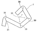
도 2는 도 1에 도시된 공작물(2)로서 본 발명에 따른 방법에 의하여 제조된, 본 발명에 따른 강철 프로필(1)의 실시예의 측면도를 도시한다. 동일한 부재들, 또는 동일한 기능을 갖는 부재들이 여기서 동일한 도면부호로 표시되어 있다. Fig. 2 shows a side view of an embodiment of a steel profile 1 according to the invention, produced by the method according to the invention as the
제조 공정에서 형성된 압입자국은 벤딩에 의해 폐쇄된다. 강철 프로필은 용접 심(30)을 가지며, 이 용접 심에 의하여 압입자국이 강철을 보강하기 위해 견고하게 폐쇄된다. 벤드의 내측면(31) 또는 벤드의 외측면에서, 용접 심이 관찰 방향에서 강철 프로필(1)을 따라 연장하고, 도 1에 도시된 측면(1)을 따라 공작물(2) 내로 부분적으로 연장한다. The indentation marks formed in the manufacturing process are closed by bending. The steel profile has a
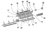
도 3은 공작물로부터 강철 프로필을 제조하기 위해 본 발명에 따른 시스템(40)의 실시예를 도시한다. 공급 장치(41)는 강철 스트립이 컷팅 장치(43)에서 추가의 제조 공정을 위한 적절한 크기의 공작물(44)로 분할될 수 있도록 강철 스트립 코일(42)로부터 강철 스트립을 제거한다. 또한, 시스템은 추가의 제조 공정을 위한 공작물의 팔레트(51)로부터 공작물(52)을 제거하는 제2 공급 장치(50)를 갖는다. 3 shows an embodiment of a
전달 요소(55)는 밀링 유닛(57)의 형태로 제공되어 있는 취약화 장치(56)로 가공되도록 하기 위해 공작물(44, 52)을 안내한다. The
밀링 유닛(57)이 공작물에서 압입자국을 형성한 후, 공작물(44, 52)은 전달 요소(55)에 의하여 공작물(44, 52)을 벤딩하기 위한 벤딩 장치(60)로 안내된다. After the
벤딩 후에, 공작물(44, 52)은 레이저 장치(61)로 이송되고, 여기서 공작물의 압입자국이 폐쇄된다. 용접 후 강철 프로필(58)은 전달 요소(55)에 의하여 스택(59) 상에 옆으로 놓여질 수 있다. After bending, the
시스템(40)은 중앙 제어기(62)에 의해 제어된다. The
도 4a 및 도 4b는 본 발명에 따른 방법의 제2 실시예를 도시한다. 특히, 도 4a 및 도 4b는 각각 벤딩 전(상단) 및 벤딩 후(하단) 공작물(400)의 두 중간 상태를 도시한다. Figures 4A and 4B show a second embodiment of the method according to the invention. In particular, Figures 4a and 4b show two intermediate states of the
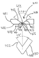
도 4a는 공작물(400)의 끝 부분(401)을 도시하고, 여기서 단부(402)가 예리한 에지가 없이 라운딩되어 있다. 도 4a에서 상단에 도시된 중간 상태에서, 공작물(400)의 압입자국(410)은 W-형상 영역(411) 및 V-형상 영역(412)을 갖는다. W-형상 영역(411)은 제1 V-형상 영역(420) 및 제2 V-형상 영역(421)으로 이루어진다. V-형상 영역(412)의 제1 측면(413)은 관찰 방향에서 볼 때 좌측에서 제1 V-형상 영역(420)의 제1 측면(422)에 인접한다. V-형상 영역(412)의 제2 측면(423)은 제2 V-형상 영역(421)의 제1 측면(424)에 인접한다. 제2 V-형상 영역(421)의 제2 측면(425)은 V-형상 영역(412)의 제2 측면(414)에 인접한다. 관찰 방향에서 볼 때 좌측에서 우측으로 진행하면서, 압입자국(410)은 다음의 인접한 요소들: 즉 V-형상 영역(412)의 제1 측면(413), 제1 V-형상 영역(420)의 제1 측면(422), 제1 V-형상 영역(420)의 제2 측면(423), 제2 V-형상 영역(421)의 제1 측면(424), 제2 V-형상 영역(421)의 제2 측면(425), 및 V-형상 영역(412)의 제2 측면(414)으로 형성된다. 4A shows the
제1 측면(413)과 제2 측면(414) 사이의 개방 각도는 대략 110°이다. The opening angle between the
하단에서, 도 4a는 벤딩 후 중간 상태에 있는 공작물(400)을 도시한다. 벤딩 중에, 공작물은 대략 110°의 벤드 각으로 구부러지고, 따라서 관찰 방향에서 볼 때, 공작물(400)의 끝 부분(401)과 우측 부분(430) 사이에 대략 70°의 개방 각도를 초래한다. 벤딩 후, 각각의 V-형상 영역 또는 부분의 측면들은 서로 닿게 놓이며 및/또는 제로 갭을 형성하며, 즉 측면(413)은 측면(414)과 함께 제로 갭을 형성하고, 측면(422)은 측면(423)과 함께 제로 갭을 형성하고, 측면(424)은 측면(425)과 함께 제로 갭을 형성한다. At the bottom, Figure 4a shows the
도 4b는 실질적으로 압입자국(410)과 유사하게 형성되어 있는 압입자국(441)을 갖는 공작물(440)을 도시한다. 동일한 부재들, 또는 동일한 기능을 갖는 부재들은 여기서 동일한 도면부호로 표시되어 있다. 도 4b에 도시된 압입자국(441)에서, 제1 측면(413)과 제2 측면(414) 사이의 개방 각도는 대략 90°이다. 벤딩 중에, V-형상 영역(412)의 측면들(413, 414)과, W-형상 영역(411)의 측면들(422, 423) 및 측면들(424, 425)은 각자 제로 갭을 형성하여서, 서로를 향하여 구부러진 구역(445)과 구역(446) 사이에 대략 90°의 각도가 만들어진다. 4B shows
도 4c는 실질적으로 압입자국(410)(도 4a) 및 압입자국(441)(도 4b)과 유사하게 형성되어 있는 압입자국(451)을 갖는 공작물(450)을 도시한다. 동일한 부재들, 또는 동일한 기능을 갖는 부재들은 여기서 동일한 도면부호로 표시되어 있다. 도 4c에 도시된 압입자국(451)에서, 제1 측면(413)과 제2 측면(414) 사이의 개방 각도는 대략 50°이다. 벤딩 중에, V-형상 영역(412)의 측면들(413, 414)과, W-형상 영역(411)의 측면들(422, 423) 및 측면들(424, 425)은 각자 제로 갭을 형성하여서, 서로를 향하여 구부러진 구역(445)과 구역(446) 사이에 대략 130°의 각도가 만들어진다. Figure 4c shows
도 5는 제1 시트 파일(511) 및 제2 시트 파일(521)의 각자의 구역(510, 520)을 도시한다. 제1 시트 파일(511)은 제2 시트 파일(521)의 로크 부재(522)와 결합하는 로크 부재(512)를 갖는다. 도 5를 참고하면, 0°보다 큰 양의 값을 갖는 정해진 각도는 시계방향(530)에서 측정된 각도로 이해해야 하고; 0°보다 작은 음의 값을 갖는 정해진 각도는 반시계방향에서 측정된 각도로 이해해야 한다. 5 shows
제1 시트 파일(511)의 로크 부재(512)는 네크 스트립(513) 및 클로 스트립(514)에 의해 형성된다. 네크 스트립(513)은 실질적으로 직각(대략 -90°)으로 제1 시트 파일(511)의 벽 구역(515)에서 연장한다. 그러한 각도를 달성하는데 필요한 공작물의 벤딩은 예를 들어, 도 4a에 도시된 공작물(440)의 중간 상태를 거쳐 실시될 수 있다. 클로 스트립(514)은 대략 -110°의 각도 α에서 네크 스트립(513)으로부터 연장한다. 예로서 대략 110°의 그러한 각도를 달성하는데 필요한 공작물의 벤딩은 예로서 도 4a에 도시된 공작물(400)의 중간 상태를 거쳐 실시될 수 있다. 클로 스트립(514)의 단부는 동시에 제1 시트 파일(511)의 단부(502)를 형성한다. 상기 단부(502)는 라운딩되고 적어도 시트 파일 단면의 관점에서 예리한 에지를 갖지 않는다. 제2 시트 파일(521)의 로크 부재(522)는 네크 스트립(523), 헤드 스트립(524), 전방 스트립(525) 및 클로 스트립(526)에 의해 형성된다. 네크 스트립(523)은 실질적으로 직각(대략 +90°)으로 제2 시트 파일(521)의 벽 구역(527)에서 연장한다. 헤드 스트립(524)은 실질적으로 직각(대략 -90°)으로 네크 스트립(523)에서 연장한다. 전방 스트립(525)은 실질적으로 직각(대략 -90°)으로 헤드 스트립(524)에서 연장한다. 그러한 직각을 달성하는데 필요한 공작물의 벤딩은 예를 들어, 도 4b에 도시된 공작물(440)의 중간 상태를 거쳐 실시될 수 있다. 클로 스트립(526)은 이에 대해 대략 -110°의 각도 β에서 전방 스트립(525)으로부터 연장한다. 그러한 대략 -110°의 각도를 달성하는데 필요한 공작물의 벤딩은 예로서 도 4a에 도시된 공작물(400)의 중간 상태를 거쳐 실시될 수 있다. 클로 스트립(526)의 단부는 제2 시트 파일(521)의 단부(503)를 동시에 형성한다. 상기 단부(503)는 라운딩되고 적어도 시트 파일 단면의 관점에서 예리한 에지를 갖지 않는다. The
네크 스트립(523), 헤드 스트립(524), 및 전방 스트립(525)은 시트 파일(521)의 U-형 영역(528)을 형성한다. 벽 구역(527)과 연합하여 U-형 영역(528)은 시트 파일(521)의 낫(sickle) 모양의 영역을 형성한다. 이에 의하여 클로 스트립(526)은 U-형 영역(528) 및/또는 낫 모양의 영역에 의해 형성된 내부 공간(529)으로 돌출한다. 도 5에 도시된 배치(arrangement)에서, 벽 구역(515, 527)은 서로 평행하게 정렬되고 동일한 평면에서 배열된다. The
벽 구역(515, 527)들이 서로를 향해 이동되면, 로크 부재(512, 522)들은 그들의 전방 스트립(513, 523)에서 서로 접한다. 시트 파일들(511, 521) 사이에 인장력이 작용하는 경우, 즉 시트 파일이 벽 구역의 연장 방향에서 강한 힘에 의해 벌어질 때, 로크 부재들은 클로 스트립(514)의 단부(502)가 전방 스트립(525)과 접하고 클로 스트립(526)의 단부(503)가 네크 스트립(513)과 접하도록 하는 방법으로 서로 결합한다. 인터록은 압력이 예를 들어 시트 파일(511, 512)의 연장부의 길이 방향에 대해 횡단하여 가해질 때 로크된 채로 유지된다. 도 5를 관찰 방향에서 상호 로크된 시트 파일들을 단지 변위시킴으로써 시트 파일들을 서로 분리시킬 수 있다. When the
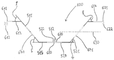
도 6은 2개의 시트 파일을 포함하는 시트 파일 벽(600)의 구역을 도시한다. 도 6에 도시된 시트 파일은 도 5에 도시된 시트 파일과 유사하다. 동일한 부재들, 또는 동일한 기능을 갖는 부재들은 여기서 동일한 도면부호로 표시되어 있다. 제1 시트 파일(511)은 실질적으로 Z-형 프로필을 갖도록 제조되고, 일 단부(610)(우측)에서 로크 부재(512)를 갖는 제1 벽 구역(515)을 포함한다. 제2 시트 파일(521)은 실질적으로 Z-형 프로필을 갖도록 제조되고, 일 단부(620)(좌측)에서 로크 부재(522)를 갖는 제1 벽 구역(527)을 포함한다. FIG. 6 shows a section of a
제1 시트 파일(511)의 제1 벽 구역(515)에서부터, 제1 시트 파일(511)의 제2 벽 구역(640)은 대략 +50°의 각 ζ에서 제1 벽 구역(515)으로 연장한다. 제2 벽 구역(640)에서부터, 제1 시트 파일(511)의 제3 벽 구역(613)은 대략 -50°의 각 ρ에서 제2 벽 구역(640)으로 연장한다. 일 단부(611)에서, 제3 벽 구역(613)은 제2 시트 파일(521)의 로크 부재(522)와 실질적으로 동일한 구조를 갖는 로크 부재(612)를 갖는다. 즉 로크 부재(612)는 평면(630)에서 거울상으로 볼 때 로크 부재(522)와 동일한 형상을 갖는다. From the
제2 시트 파일(521)의 제1 벽 구역(527)에서부터, 제2 시트 파일(521)의 제2 벽 구역(641)은 대략 -50°의 각 π에서 제1 벽 구역(527)으로 연장한다. 제2 벽 구역(641)에서부터, 제2 시트 파일(527)의 제3 벽 구역(614)은 대략 +50°의 각 ξ에서 제2 벽 구역(641)으로 연장한다. 일 단부(621)에서, 제3 벽 구역(614)은 제1 시트 파일의 로크 부재(512)와 실질적으로 동일한 구조를 갖는 로크 부재(622)를 갖는다. 즉 로크 부재(622)는 평면(630)에서 거울상으로 볼 때 로크 부재(512)와 동일한 형상을 갖는다. The
도 7은 강철 스트립 블랭크(702)로부터 시트 파일(701)을 제조하기 위해 본 발명에 따른 시스템(700)의 제2 실시예를 도시한다. 강철 스트립 블랭크(702)는 공급장치(704)에 의하여 강철 스트립 코일(703)로부터 펼쳐지고 운반 방향(710)에서 시스템(700)의 다음 구성요소로 공급 방향(710)에서 공급된다. 운반 장치(711)는 시스템(700)의 개별 구성요소를 따라 및/또는 통하여 공급 방향(710)에서 강철 블랭크(702)를 운반하는데 사용된다. 7 illustrates a second embodiment of a
강철 스트립 블랭크(702)는 공급 장치(704)로부터 밀링 장치(712)로 진행하고, 밀링 장치에 의하여 취약 지점으로서 제공된 압입자국이 강철 스트립 블랭크(702)에 도입된다. 밀링 장치(712)는 2개의 밀링 유닛(713, 714)을 갖는다. 밀링 유닛(713)에 의하여 압입자국이 먼저 아래에서부터 강철 스트립 블랭크(702)에 도입된다. 밀링 유닛(714)에 의하여 압입자국이 위에서부터 강철 스트립 블랭크(702)에 도입된다. The steel strip blank 702 advances from the
레이저 컷팅 장치(720)가 강철 스트립 블랭크(702)에 슬롯형 컷아웃들(cut-outs)을 도입하는데 사용된다. 컷아웃들 각각은 강철 스트립 블랭크(702)의 외측 에지에서부터 실질적으로 직선으로 강철 스트립 블랭크(702) 내로 공급 방향(710)에 대해 횡단하여 연장한다. 특히, 2개의 컷은 공급 방향(710)에서 사전규정된 거리에서, 소위 강철 스트립 블랭크(702)의 측방향 에지에서부터 사전규정된 길이 만큼 내향으로 만들어진다. 컷은 특히, 운반 장치(711)에 위치한 전체 강철 스트립 블랭크(702)로 전달되는 벤딩 모멘트가 없이, 다음 제조 공정에서 벤드가 만들어지도록 하기 위하여 만들어진다. 컷은 이러한 지점에서 강철 스트립 블랭크(702)에 도입되며, 여기서 공작물은 후속 제조 공정에서 강철 스트립 블랭크(702)로부터 연속적으로 절단된다. A laser cutting device 720 is used to introduce slotted cut-outs into the steel strip blank 702. Each of the cutouts extends transversely to the
시스템(700)의 벤딩 장치(725)는 다른 지점에서 강철 스트립 블랭크(702)에 적용된다. 벤드의 영역에서, 벤딩 중에 형성된 제로 갭은 레이저 장치(730)에 의하여 폐쇄된다. 용접 후, 개별 공작물이 컷팅 장치(740)에 의하여 강철 블랭크(702)로부터 절단된다. 마무리된 공작물은 다음에 예를 들어 배송되기 위해 스택(750)에 저장될 수 있다. The bending device 725 of the
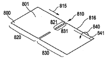
도 8은 강철 스트립 블랭크(801)의 형태로 구체화된 본 발명에 따른 공작물(800)의 일부의 사시도를 도시한다. 압입자국(810)이 강철 스트립 블랭크(801)에 도입되며, 이는 강철 스트립 블랭크(801)의 연장부(815)의 길이 방향에 대해 횡단하여 강철 스트립 블랭크(801)로 측방향으로 연장하며, 강철 스트립 블랭크의 측방향 에지(816)로 개방된다. 제1 영역(820)은 압입자국(810)의 제1 부분(821)을 한정한다. 제2 영역(830)은 압입자국(810)의 제2 부분(831)을 한정한다. 이에 의하여 벤딩 모멘트(840)가 파선으로 나타난 축(841)에 대해 토크의 형태로 강철 스트립 블랭크(801)의 제2 영역(830)에 가해질 수 있다. 즉 관찰 방향에서 볼 때 파선(841) 아래에 도시된 강철 스트립 블랭크의 영역은 그 위치가 유지되고, 반면에 관찰 방향에서 보아서 파선(841)보다 위에 도시된 강철 스트립 블랭크(801)의 에지는 축(841)에 대해 토크에 노출되어 있다. 압입자국(810)으로 인하여, 이러한 종류의 벤딩 모멘트(840)가 강철 스트립 블랭크(801)의 제1 영역(820)으로 전달되지 않는다. 즉 이러한 벤딩 모멘트가 제1 영역(820)에 전달되지 않으며 및/또는 제1 영역(820)에 어떠한 효과를 주지 않으면서 벤드가 제2 영역(830)에서 실시될 수 있다. Figure 8 shows a perspective view of a portion of a
도 9는 벤딩 후에 중간 상태에서 도 8에 도시된 강철 스트립 블랭크(801)의 사시도를 도시한다. 즉 도 8에 도시된 강철 스트립 블랭크(801)는 시트 파일을 제조하기 위하여 강철 스트립 블랭크(801)에서 제조 공정 동안 실시되는 벤딩 작업을 받았다. 도 9는 기본적으로 제조 공정에서 후속 단계로 서로 분리되는 2개의 시트 파일(901, 902)을 도시한다. Figure 9 shows a perspective view of the steel strip blank 801 shown in Figure 8 in an intermediate state after bending. That is, the steel strip blank 801 shown in FIG. 8 was subjected to a bending operation performed during the manufacturing process in the steel strip blank 801 to produce the sheet pile. Figure 9 shows two
도 10은 제1 시트 파일(1011) 및 제2 시트 파일(1021)의 각자의 구역(1010, 1020)을 도시한다. 제1 시트 파일(1011)은 제2 시트 파일(1021)의 로크 부재(1022)와 결합하는 로크 부재(1012)를 갖는다. 도 10을 참고하면, 0°보다 큰 양의 값을 갖는 정해진 각도는 시계방향(1030)에서 측정된 각도로 이해해야 하고; 0°보다 작은 음의 값을 갖는 정해진 각도는 반시계방향에서 측정된 각도로 이해해야 한다. 10 shows the
제1 시트 파일(1011)의 로크 부재(1012)는 네크 스트립(1013) 및 클로 스트립(1014)에 의해 형성된다. 네크 스트립(1013)은 +38°의 각도 ω에서 제1 시트 파일(1011)의 벽 구역(1015)에서 연장한다. 클로 스트립(1014)은 대략 +123°의 각도 Ψ에서 네크 스트립(1013)으로부터 연장한다. 클로 스트립(1014)의 단부는 동시에 제1 시트 파일(1011)의 단부(1002)를 형성한다. 상기 단부(1002)는 라운딩되고 적어도 시트 파일 단면의 관점에서 예리한 에지를 갖지 않는다. The locking
제2 시트 파일(1021)의 로크 부재(1022)는 네크 스트립(1023), 헤드 스트립(1024), 전방 스트립(1025) 및 클로 스트립(1026)에 의해 형성된다. 네크 스트립(1023)은 실질적으로 -49.5°의 각도 χ에서 제2 시트 파일(1021)의 벽 구역(1027)에서 연장한다. 헤드 스트립(1024)은 대략 +30.5°의 각도 φ에서 네크 스트립(1023)에서 연장한다. 전방 스트립(1025)은 대략 +57°의 각도 σ에서 헤드 스트립(1024)에서 연장한다. 클로 스트립(1026)은 대략 +123°의 각도 Ψ에서 전방 스트립(1025)으로부터 연장한다. 클로 스트립(1026)의 단부는 제2 시트 파일(1021)의 단부(1003)를 동시에 형성한다. 상기 단부(1003)는 라운딩되고 적어도 시트 파일 단면의 관점에서 예리한 에지를 갖지 않는다. 도 10에 도시된 배치에서, 벽 구역(1015, 1027)은 서로 평행하게 정렬되고 동일한 평면에서 배열된다. The
시트 파일들(1011, 1021) 사이에 인장력이 작용하는 경우, 즉 시트 파일들이 강한 힘에 의해 벌어질 때, 로크 부재들은 클로 스트립(1014)의 단부(1002)가 전방 스트립(1025) 및 클로 스트립(1026)과 접하고 클로 스트립(1026)의 단부(1003)가 네크 스트립(1013) 및 클로 스트립(1014)과 접하도록 하는 방법으로 서로 결합한다. 인터록은 압력이 예를 들어 시트 파일(1011, 1021)의 연장부의 길이 방향에 대해 횡단하여 가해질 때 로크된 채로 유지된다. 도 10을 관찰 방향에서 상호 로크된 시트 파일들을 단지 변위시킴으로써 시트 파일들을 서로 분리시킬 수 있다. When the tension forces are applied between the sheet files 1011 and 1021, that is, when the sheet files are pulled by the strong force, the locking members move the
도 11 및 도 12는 각각 2개의 시트 파일을 포함하는 시트 파일 벽(1100)의 구역을 도시한다. 도 11은 사시도를 도시하고, 도 12는 시트 파일 벽(1100)의 단면을 도시한다. 도 11 및 도 12에 도시된 시트 파일은 도 10에 도시된 시트 파일과 구조가 유사하다. 동일한 부재들, 또는 동일한 기능을 갖는 부재들은 여기서 동일한 도면부호로 표시되어 있다. 제1 시트 파일(1011)은 실질적으로 Z-형 프로필을 갖도록 제조되고, 일 단부(1110)(우측)에서 로크 부재(1012)를 갖는 제1 벽 구역(1015)을 포함한다. 제2 시트 파일(1021)은 실질적으로 Z-형 프로필을 갖도록 제조되고, 일 단부(1120)(좌측)에서 로크 부재(1022)를 갖는 제1 벽 구역(1027)을 포함한다. Figs. 11 and 12 illustrate a section of a
제1 시트 파일(1011)의 제1 벽 구역(1015)에서부터, 제1 시트 파일(1011)의 제2 벽 구역(1140)은 대략 -50°의 각 ν에서 제1 벽 구역(1015)으로 연장한다. 제2 벽 구역(1140)에서부터, 제1 시트 파일(1011)의 제3 벽 구역(1113)은 대략 +50°의 각 μ에서 제2 벽 구역(1140)으로 연장한다. 일 단부(1111)에서, 제3 벽 구역(1113)은 제2 시트 파일(1021)의 로크 부재(1022)와 실질적으로 동일한 구조를 갖는 로크 부재(1112)를 갖는다. 즉 로크 부재(1112)는 평면(1130)에서 거울상으로 볼 때 로크 부재(1022)와 동일한 형상을 갖는다. From the
제2 시트 파일(1021)의 제1 벽 구역(1027)에서부터, 제2 시트 파일(1021)의 제2 벽 구역(1141)은 대략 +50°의 각 λ에서 제1 벽 구역(1027)으로 연장한다. 제2 벽 구역(1141)에서부터, 제2 시트 파일(1021)의 제3 벽 구역(1114)은 대략 -50°의 각 κ에서 제2 벽 구역(1141)으로 연장한다. 일 단부(1121)에서, 제3 벽 구역(1114)은 제1 시트 파일의 로크 부재(1012)와 실질적으로 동일한 구조를 갖는 로크 부재(1122)를 갖는다. 즉 로크 부재(1122)는 평면(1130)에서 거울상으로 볼 때 로크 부재(1012)와 동일한 형상을 갖는다. The
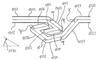
도 13은 도 10에 도시된 로크 부재(1022)의 일부의 단면을 도시한다. 이러한 단면은 벤딩 단계 후에 실시되는 용접 작업을 예시한다. 특히, 도 13은 클로 스트립(1026)과, 전방 스트립(1025)의 일부를 도시한다. 벤딩 후에, 제로 갭은 압입자국의 측면에 의해, 예로서 도 4a에 도시된 바와 같이 측면(413, 414)에 의해 형성된다. 제로 갭을 폐쇄(용접)하기 위하여, 레이저 빔(1310)이 벤드의 외측면(1320)에서부터 벤드의 내측면(1321)으로 향하게 된다. 레이저 빔(1310)은 실질적으로 제로 갭을 따라서 공작물(1300) 내측으로 나아간다. 용접 후에, 용접 루트(root)(1330)가 용접 심의 벤드 외측면(1320)에 형성되고, 용접 루트(1331)가 용접 심의 벤드 내측면(1321)에 형성된다. 공작물(1300) 내측에서, 두 영역(1340, 1341)이 용접 후에 형성된다. 영역(1340)은 용접 중에 완전히 용해되는 실질적으로 삼각형 용접 코어(1345)에 의해 형성된다. 영역(1341)은 용접 작업에 포함되지 않는 공작물의 영역(1346)과 용접 코어(1345) 사이의 전이 영역에 의해 형성된다. 벤드 외측면(1320)으로부터의 용접은 쐐기형 용접 루트가 형성되며 그 팁(tip)이 벤드 내측면(1340)을 향해 배향되는 것을 보장한다. 레이저 빔(1310)의 초점(1350)은 공작물(1300) 내측, 특히 영역(1340) 내에 있다. 이러한 초점 위치, 즉 공작물 내측에 있는 초점 위치(레이저 빔이 공작물을 타격하는 지점에서 진행하는)는 넓은 루트를 보장하고, 그 결과 벤드 외측면의 넓은 영역이 영향을 받게 된다. 특히 구부러진 상태에서 더브테일(dovetail) 형식으로 외부로 돌출하는 W-형상 압입자국의 경우, 따라서 벤딩 중에 형성된 제로 갭을 용해할 수 있다. 벤딩 중에 변형된 영역도 역시 용해되고, 그 결과 조인트가 사전에 구부러진 상태에서보다 냉각 후에 더 작은 스트레인을 받는다. Fig. 13 shows a cross section of a part of the
용접을 위해 사용되는 레이저 빔(1310)은 바람직하게 10kW 내지 14kW(킬로와트)의 전력 소요량을 갖는다. 대략 110°의 벤드 각도에 대해서, 레이저 용접 빔의 전력 소요량은 바람직하게 약 14kW이고, 바람직한 초점 위치는 대략 14mm이며; 대략 90°의 벤드 각도에 대해서, 레이저 용접 빔의 전력 소요량은 바람직하게 약 12kW이고, 바람직한 초점 위치는 대략 -16mm이며; 대략 50°의 벤드 각도에 대해서, 레이저 용접 빔의 공칭 전력은 바람직하게 약 10kW이고, 바람직한 초점 위치는 대략 -8mm이다. 레이저 용접 빔은 바람직하게 용접 중에 도 13의 관찰 방향에서, 1.5 내지 1.8 m/min(분당 미터)의 속도로 용접될 공작물을 따라 이동한다. The
2, 44, 52 공작물
10 취약 지점
11 압입자국
21 벤드2, 44, 52 Workpiece
10 vulnerable points
11 indentation marks
21 Bend
Claims (31)
공작물(2, 44, 52), 특히 강철 블랭크(blank), 바람직하게는 강철 스트립 블랭크를 제공하는 단계,
상기 공작물(2, 44, 52)에서 계획된 벤드(bend)의 영역에서 취약 지점(10)을 형성하는 단계, 및
상기 공작물(2, 44, 52)에서 벤드를 형성하기 위해 상기 공작물(2, 44, 52)을 벤딩(bending)하는 단계를 포함하는 강철 프로필 제조방법.A method of making a steel profile,
Providing the workpiece 2, 44, 52, in particular a steel blank, preferably a steel strip blank,
Forming a weak point (10) in the area of the planned bend in the workpiece (2, 44, 52); and
Bending the workpiece (2, 44, 52) to form a bend in the workpiece (2, 44, 52).
상기 취약 지점(10)은 상기 공작물(2, 44, 52)에서 압입자국(indentation)(11), 특히 노치(notch)를 형성함으로써 형성되는 강철 프로필 제조방법. The method according to claim 1,
The weak point (10) is formed by forming an indentation (11), in particular a notch, in the workpiece (2, 44, 52).
상기 취약 지점(10), 특히 상기 취약 지점(10)을 형성하는 압입자국(11)은 밀링, 압연, 펀칭 또는 스탬핑에 의하여 형성되는 강철 프로필 제조방법. The method according to claim 1 or 2,
Wherein the weak point (10), in particular the indentation mark (11) forming the weak point (10), is formed by milling, rolling, punching or stamping.
상기 취약 지점(10)은 벤딩 후에 용접, 특히 레이저 용접, 및 바람직하게는 레이저 하이브리드 용접 기술에 의하여 보강되는 강철 프로필 제조방법. The method according to any one of claims 1 to 3,
The weak point (10) is reinforced by welding after bending, in particular by laser welding, and preferably by laser hybrid welding techniques.
상기 취약 지점(10)을 형성하는 압입자국(11)이 상기 공작물(2, 44, 52)에서 벤드(21)의 내측면에 형성되며, 벤딩 중에 크기가 감소되거나 또는 폐쇄되며, 또는
상기 취약 지점(10)을 형성하는 압입자국(11)이 상기 공작물(2, 44, 52)에서 벤드(21)의 외측면에 형성되며, 벤딩 중에 확장되는 강철 프로필 제조방법. 5. The method according to any one of claims 1 to 4,
An indentation mark 11 forming the weak point 10 is formed in the inner surface of the bend 21 in the workpiece 2, 44, 52 and is reduced in size or closed during bending,
An indentation mark (11) forming the weak point (10) is formed on the outer surface of the bend (21) in the workpiece (2, 44, 52) and is expanded during bending.
압입자국(11)이 상기 공작물(2, 44, 52)에서 상기 취약 지점(10)을 형성하며, 상기 공작물(2, 44, 52)에서 벤드(21)의 내측면에 형성된 상기 압입자국(11)은 벤딩 후에 용접, 특히 레이저 용접에 의하여 폐쇄되는 강철 프로필 제조방법. The method according to any one of claims 1 to 5,
A press-in impression station (11) forms the weak point (10) at the work piece (2, 44, 52) ) Is closed after welding by bending, in particular by laser welding.
용접은 공작물(1300)에 있는 벤드(1320)의 외측면으로부터 벤드(1321)의 내측면으로 특히, 벤딩 후 압입자국(410)에 의해 형성된 제로 갭(zero gap)을 따라서 조준되는 집속된 레이저 빔(1310)을 사용하여 이루어지고, 상기 빔의 초점은 바람직하게 상기 공작물(1300) 내부에 있는 강철 프로필 제조방법. The method of claim 6,
The weld is directed from the outer side of the bend 1320 in the workpiece 1300 to the inner side of the bend 1321 and in particular to the focused laser beam 130 that is aimed along a zero gap formed by the indentation station 410 after bending. (1310), and the focus of the beam is preferably within the workpiece (1300).
상기 취약 지점(10)을 형성하는 압입자국(11)을 규정하는 측면(16)들은 다함께 분리되지 않게 결합되는 강철 프로필 제조방법. The method according to any one of claims 1 to 7,
Wherein the side faces (16) defining the indentation station (11) forming the weak point (10) are joined together in a non-separable manner.
벤딩은 자유 벤딩, 폴딩(folding) 또는 다이 벤딩(die bending)에 의해 실시되는 강철 프로필 제조방법. The method according to any one of claims 1 to 8,
Wherein the bending is performed by free bending, folding or die bending.
상기 공작물(2, 44, 52)은 강철 스트립 롤(42), 특히 코일을 펼침(unrolling)으로써 제공되는 강철 프로필 제조방법. The method according to any one of claims 1 to 9,
The workpiece (2, 44, 52) is provided by a steel strip roll (42), in particular by unrolling the coil.
압입자국(810)이 강철 스트립 블랭크(801)의 형태로 된 공작물(800)에 벤딩 전에 도입되고, 상기 압입자국은 상기 강철 스트립 블랭크의 길이방향(815)에 대해 실질적으로 횡단하여 배향되며 상기 강철 스트립 블랭크(801)의 측방향 에지(816)에서 개방되는 강철 프로필 제조방법. The method according to any one of claims 1 to 10,
An indentation mark 810 is introduced into the workpiece 800 in the form of a steel strip blank 801 before bending and the indentation mark is oriented substantially transverse to the longitudinal direction 815 of the steel strip blank, And is opened at a lateral edge (816) of the strip blank (801).
상기 압입자국(810)은, 상기 압입자국(810)의 제1 부분(821)을 제한하는 상기 강철 스트립 블랭크(801)의 제1 영역(820)에서의 벤딩 모멘트(840)가 상기 압입자국(810)의 제2 부분(831)을 제한하는 상기 강철 스트립 블랭크(801)의 제2 영역(830)으로 전달되지 않도록, 상기 강철 스트립 블랭크(801) 내로 돌출하는 강철 프로필 제조방법. The method of claim 11,
The indenting station 810 is configured such that a bending moment 840 in the first area 820 of the steel strip blank 801 that limits the first portion 821 of the indenting station 810 is greater than the bending moment 840 in the first area 820 of the steel strip blank 801, (801) of the steel strip blank (801) that limits the second portion (831) of the steel strip blank (810).
벤딩 영역에서 취약 지점(10)을 갖는 공작물(2, 44, 52)을 포함하는 강철 프로필. A steel profile, in particular a steel profile produced by a method of manufacturing a steel profile according to any one of claims 1 to 12,
A steel profile comprising a workpiece (2, 44, 52) having a weak point (10) in a bending area.
상기 취약 지점(10)은 상기 공작물(2, 44, 52)에서 압입자국(11)으로서 형성되는 강철 프로필. 14. The method of claim 13,
The weak point (10) is formed as an indentation mark (11) in the workpiece (2, 44, 52).
상기 공작물(2, 44, 52)은 벤딩 영역에서 실질적으로 V-형상 압입자국(11)을 가지며, 상기 압입자국(11)의 측면(16)들은 바람직하게 90°내지 135° 범위의 각도를 형성하는 강철 프로필. The method according to claim 13 or 14,
The workpiece (2, 44, 52) has a substantially V-shaped indentation mark (11) in the bending region and the sides (16) of the indentation mark (11) preferably form an angle in the range of 90 to 135 Steel profiles.
상기 공작물(400)은 벤딩 영역에서 실질적으로 W-형상 압입자국을 가지는 강철 프로필. The method according to any one of claims 13 to 15,
The workpiece (400) has a substantially W-shaped indentation mark in the bending region.
상기 공작물(400)은 제1 영역(412)에서 V-형상이며, 제2 영역(425), 특히 압입자국(410)의 바닥 영역에서 W-형상인 압입자국(410)을 가지며,
V-형상 영역(412)의 측면들(413, 414)은 바람직하게 대략 50°내지 110°범위의 각도를 형성하는 강철 프로필. The method according to any one of claims 13 to 16,
The workpiece 400 is V-shaped in a first region 412 and has a second region 425, particularly a W-shaped indentation station 410 in the bottom region of the indentation station 410,
The sides 413 and 414 of the V-shaped region 412 preferably form an angle in the range of approximately 50 ° to 110 °.
상기 W-형상 압입자국의 측면들은, 특히 상기 W-형상 압입자국의 각각의 외측면들이 V-형상 압입자국의 측면들과 인접하도록 하는 방식으로 V-형상 압입자국의 측면들과 인접하는 강철 프로필. The method according to claim 16 or 17,
The sidewalls of the W-shaped indentation station are arranged in such a way that the steel profiles adjacent to the sides of the V-shaped indentation station, in particular in such a manner that the outer surfaces of each of the W-shaped indentation stations are adjacent to the sides of the V- .
상기 공작물(2, 44, 52)은, 상기 벤딩 영역(12)에서의 상기 취약 지점(10)을 보강하기 위해 용접 심(weld seam)(30), 특히 레이저 용접 심을 가지는 강철 프로필. The method according to any one of claims 13 to 18,
The workpiece (2, 44, 52) has a weld seam (30), particularly a steel profile having a laser welded core, for reinforcing the weak point (10) in the bending region (12).
시트 파일(511; 1011)을 다른 시트 파일(521; 1021) 또는 지지 요소의 로크 부재(522; 1022)에 연결하기 위한 로크 부재(512; 1012)를 포함하고,
상기 로크 부재(512; 1012)는 상기 시트 파일(511; 1011)의 벽 구역(515; 1015)으로부터, 특히 실질적으로 직각으로 연장하는 네크 스트립(neck strip)(513; 1013), 및 상기 네크 스트립(513, 1013)으로부터 연장하는 클로 스트립(claw strip)(514, 1014)을 포함하고,
상기 클로 스트립(514; 1014)은 적어도 90°의 각도(α; Ψ), 특히 100°내지 130°의 각도로 실질적으로 상기 네크 스트립(513; 1013)을 향해 배향되고, 상기 클로 스트립(514; 1014)의 일 단부(502; 1002)는 상기 벽 구역(515; 1015)과 마주보는 시트 파일. As a sheet file, especially a Z sheet file,
A lock member 512 (1012) for connecting the sheet file 511 (1011) to another sheet file 521 (1021) or a locking member (522; 1022)
The locking member 512 (1012) includes a neck strip 513 (1013) extending from the wall section 515 (1015) of the sheet pile 511 (1011), in particular at a substantially right angle, And a claw strip (514, 1014) extending from the base (513, 1013)
The clot strips 514 and 1014 are oriented substantially toward the neck strips 513 and 1013 at an angle of at least 90 degrees and an angle of between 100 and 130 degrees, 1014) of the sheet member (502; 1002) faces the wall section (515;
상기 네크 스트립(1013)은 최대 90°의 각도(Ψ), 특히 대략 20°내지 50°의 각도, 바람직하게 30°내지 40°의 각도로 상기 벽 구역(1015)을 향해 배향되는 시트 파일. 23. The method of claim 21,
The neck strip 1013 is oriented toward the wall section 1015 at an angle (?) Of up to 90 °, in particular an angle of about 20 ° to 50 °, preferably 30 ° to 40 °.
시트 파일(521; 1021)을 다른 시트 파일(511; 1011) 또는 지지 요소의 로크 부재(512; 1012)에 연결하기 위한 로크 부재(522; 1022)를 포함하고,
상기 로크 부재(522; 1022)는,
상기 시트 파일(521; 1021)의 벽 구역(527; 1027)으로부터, 특히 직각으로 연장하는 네크 스트립(523; 1023),
상기 네크 스트립(523, 1023)으로부터, 특히 실질적으로 직각으로 연장하는 헤드 스트립(524; 1024),
상기 헤드 스트립(524; 1024)으로부터, 특히 실질적으로 직각으로 연장하는 전방 스트립(525; 1025), 및
상기 전방 스트립(525; 1025)으로부터 연장하는 클로 스트립(526, 1026)을 포함하고,
상기 클로 스트립(526; 1026)은 적어도 90°의 각도(β; Ψ), 특히 100°내지 130°의 각도(β)로 실질적으로 상기 전방 스트립(525; 1025)을 향해 배향되며, 상기 네크 스트립(523, 1023)과 상기 헤드 스트립(524; 1024)과 상기 전방 스트립(525; 1025)에 의해 형성된 U-형 영역(528; 1028)에서 상기 전방 스트립(525; 1025)으로부터 연장하는 시트 파일. As a sheet file, especially a Z sheet file,
Includes a lock member 522 (1022) for connecting the sheet file 521 (1021) to another sheet file (511; 1011) or a locking member (512;
The locking member (522; 1022)
A neck strip 523 (1023) extending from a wall section 527 (1027) of the sheet file 521 (1021)
A head strip (524; 1024) extending from the neck strips (523, 1023), in particular at a substantially right angle,
A front strip 525 (1025) extending from the head strip 524 (1024), in particular at a substantially right angle, and
And a claw strip (526, 1026) extending from the front strip (525; 1025)
The clog strips 526 1026 are oriented substantially toward the front strips 525 1025 at an angle beta of at least 90 degrees and in particular an angle beta of 100 to 130 degrees, (525; 1025) formed in the U-shaped region (528; 1028) formed by the head strips (523, 1023) and the front strips (525; 1025).
상기 네크 스트립(1023)은 최대 90°의 각도(χ), 특히 대략 30°내지 70°의 각도, 바람직하게 45°내지 55°의 각도로 상기 벽 구역(1027)을 향해 배향되고, 및/또는
상기 헤드 스트립(1024)은 최대 90°의 각도(φ), 특히 대략 20°내지 50°의 각도, 바람직하게 30°내지 40°의 각도로 상기 네크 스트립(1023)을 향해 배향되고, 및/또는
상기 전방 스트립(1025)은 최대 90°의 각도(σ), 특히 대략 30°내지 70°의 각도, 바람직하게 45°내지 60°의 각도로 상기 헤드 스트립(1024)을 향해 배향되는 시트 파일. 24. The method of claim 23,
The neckstrip 1023 is oriented toward the wall zone 1027 at an angle (?) Of at most 90 °, in particular an angle of approximately 30 ° to 70 °, preferably an angle of 45 ° to 55 °, and /
The head strip 1024 is oriented towards the neckstrip 1023 at an angle of up to 90 degrees, in particular an angle of between about 20 and 50 degrees, preferably between 30 and 40 degrees, and /
The front strip 1025 is oriented toward the head strip 1024 at an angle? Of up to 90 占 particularly an angle of approximately 30 占 to 70 占 preferably between 45 占 and 60 占.
상기 클로 스트립(1026)은 실질적으로 120°내지 140°의 각도(Ψ)로 상기 전방 스트립(1025)을 향해 배향되는 시트 파일. The method according to claim 21 or 24,
Wherein the cloth strip (1026) is oriented toward the front strip (1025) at an angle (?) Of substantially 120 ° to 140 °.
상기 클로 스트립(514; 524)의 일 단부(402; 502; 503)는 라운딩되어(rounded) 있는 시트 파일. The method of claim 21 or 22,
Wherein one end (402; 502; 503) of the clip strip (514; 524) is rounded.
공작물(2, 44, 52)에 취약 지점(10), 특히 상기 공작물(2, 44, 52)의 계획된 벤드의 영역에 압입자국(11)을 형성하기 위한 취약화 장치(weakening device)(14, 56) 및
상기 취약 지점(10)의 영역에서 상기 공작물(2, 44, 52)을 구부리기 위한 벤딩 장치(20, 60, 725)를 포함하는 강철 프로필 제조 시스템. As a system for manufacturing steel profiles from workpieces, particularly steel blanks, preferably steel strip blanks (4, 702)
A weakening device 14 for forming the indentation mark 11 in the area of the intended bend of the weak point 10, in particular the workpiece 2, 44, 52, 56) and
(20, 60, 725) for bending the workpiece (2, 44, 52) in the region of the weak point (10).
상기 공작물(2, 44, 52), 특히 강철 블랭크, 바람직하게는 강철 스트립 블랭크(4, 702)를 제공하기 위한 공급 장치(50, 704)를 포함하는 강철 프로필 제조 시스템. 29. The method of claim 28,
(50, 704) for providing said workpiece (2, 44, 52), in particular a steel blank, preferably a steel strip blank (4, 702).
컷팅 장치(43)가 강철 스트립 코일(42)로부터 공급된 강철 스트립을 공작물(2, 44, 52)로 분할하기 위해 제공되는 강철 프로필 제조 시스템. 29. The method of claim 28 or 29,
A steel profile manufacturing system in which a cutting device (43) is provided for dividing a steel strip supplied from a steel strip coil (42) into workpieces (2, 44, 52).
컷팅 장치(720)가 압입자국(810)을 도입하도록 설계되고, 상기 압입자국(810)은 상기 강철 스트립 블랭크의 길이방향(815)에 대해 실질적으로 횡단하여 배향되고, 상기 강철 스트립 블랭크(801)의 측방향 에지(816)에서 개방되는 강철 프로필 제조 시스템. 32. The method according to any one of claims 28 to 30,
Cutting device 720 is designed to introduce the indenting station 810 and the indenting station 810 is oriented substantially transversely to the longitudinal direction 815 of the steel strip blank and the steel strip blank 801, Is open at the lateral edge (816) of the steel profile.
Applications Claiming Priority (3)
| Application Number | Priority Date | Filing Date | Title |
|---|---|---|---|
| DE102011100633A DE102011100633A1 (en) | 2011-05-05 | 2011-05-05 | Method for producing a steel profile |
| DE102011100633.1 | 2011-05-05 | ||
| PCT/EP2012/058311 WO2012150352A2 (en) | 2011-05-05 | 2012-05-04 | Method for producing a steel profiled element |
Publications (1)
| Publication Number | Publication Date |
|---|---|
| KR20140071966A true KR20140071966A (en) | 2014-06-12 |
Family
ID=46046192
Family Applications (1)
| Application Number | Title | Priority Date | Filing Date |
|---|---|---|---|
| KR1020137032255A KR20140071966A (en) | 2011-05-05 | 2012-05-04 | Method and device for producing a steel profiled element and said type of steel profiled element |
Country Status (15)
| Country | Link |
|---|---|
| US (2) | US9199292B2 (en) |
| EP (1) | EP2709778B1 (en) |
| JP (1) | JP6178307B2 (en) |
| KR (1) | KR20140071966A (en) |
| CN (1) | CN103561879B (en) |
| AU (1) | AU2012251616B2 (en) |
| BR (1) | BR112013028179A2 (en) |
| CA (1) | CA2833189C (en) |
| DE (1) | DE102011100633A1 (en) |
| EA (1) | EA027891B1 (en) |
| MX (1) | MX345308B (en) |
| MY (1) | MY167087A (en) |
| SG (1) | SG194638A1 (en) |
| WO (1) | WO2012150352A2 (en) |
| ZA (1) | ZA201307776B (en) |
Cited By (2)
| Publication number | Priority date | Publication date | Assignee | Title |
|---|---|---|---|---|
| KR101675687B1 (en) * | 2015-05-27 | 2016-11-11 | (주)파버나인 | Stand manufacturing method of a display device |
| KR20180028858A (en) * | 2016-09-09 | 2018-03-19 | 삼성전자주식회사 | Cooking appliance and method of manufacturing housing of cooking appliance |
Families Citing this family (21)
| Publication number | Priority date | Publication date | Assignee | Title |
|---|---|---|---|---|
| DE102012113088A1 (en) * | 2012-12-24 | 2014-06-26 | Tuo-Jen Chen | Manufacturing method of repair tool, involves removing one side of bending portion by trimming process to obtain certain thickness of bending portion to form working surface on surface of bending portion with smooth texture |
| DE102013215830A1 (en) | 2013-08-09 | 2015-02-12 | Origami Steel Corp. | Steel profile, support profile and method for producing a steel profile |
| DE102013222899A1 (en) | 2013-11-11 | 2015-05-13 | Origami Steel Corp. | Method for producing a steel profile, in particular a steel beam |
| CN104759893A (en) * | 2015-03-27 | 2015-07-08 | 王威 | Keel forming system and application method thereof |
| JP6630192B2 (en) * | 2016-01-25 | 2020-01-15 | 梶 塁 | High load hinge device and frame structure equipped with it |
| MX2018009900A (en) | 2016-02-16 | 2018-11-09 | Nisshin Steel Co Ltd | Laser-welded shaped steel and method for producing same. |
| DE102016214929A1 (en) * | 2016-08-11 | 2018-02-15 | Bayerische Motoren Werke Aktiengesellschaft | Method for producing a three-dimensional molded component and molded component |
| JP6947818B2 (en) * | 2016-09-20 | 2021-10-13 | オートテック・エンジニアリング・ソシエダッド・リミターダAutotech Engineering, S.L. | Reinforce structural parts |
| DE102017124443A1 (en) * | 2017-10-19 | 2019-04-25 | Brandenburgische Technische Universität Cottbus-Senftenberg | Profile with longitudinally varying cross-sectional shapes and method for its production |
| AT17787U1 (en) * | 2018-01-12 | 2023-02-15 | Blum Gmbh Julius | Drawer slide with at least one guide rail |
| BE1026099B1 (en) * | 2018-03-16 | 2019-10-14 | Kreafin Group Sa | PANEL OF WHICH THE COUPLING DEVICES ARE SUITABLE FOR CONNECTING THE LONG SIDE AND / OR KOPSE SIDE TOGETHER |
| DK180079B1 (en) | 2018-02-23 | 2020-03-31 | Kk Wind Solutions A/S | Profile for a cabinet frame |
| DE102018203922B4 (en) * | 2018-03-15 | 2021-02-04 | Volkswagen Aktiengesellschaft | Cable lug with defined crash behavior and arrangement of a cable lug |
| CN108481001A (en) * | 2018-04-23 | 2018-09-04 | 广州市捷迈智能装备制造有限公司 | It is a kind of full-automation bending, welding production line |
| US11364566B2 (en) | 2018-08-09 | 2022-06-21 | The United States Of America As Represented By The Secretary Of The Army | Complex laser folding and fabrication |
| CN110459434B (en) * | 2019-08-08 | 2021-08-17 | 安徽商贸职业技术学院 | Automatic armature machining equipment for small electromagnetic relay |
| CN112045075B (en) * | 2020-08-19 | 2022-05-24 | 福州弘泰冶金技术开发有限公司 | Turnover type steel sheet flanging machine |
| CN112165298B (en) * | 2020-09-30 | 2021-12-28 | 晶科能源股份有限公司 | Photovoltaic frame, photovoltaic assembly and manufacturing method of photovoltaic frame |
| CN112234930B (en) * | 2020-09-30 | 2022-08-05 | 晶科能源股份有限公司 | Strip-shaped section bar and photovoltaic frame |
| AU2021452413B2 (en) * | 2021-06-25 | 2023-07-20 | Sasan SAIDIAN | A stud wall restraint system for in-plane building movement isolation |
| CN114211257B (en) * | 2021-12-31 | 2023-03-28 | 中冶南方工程技术有限公司 | Welding and punching integrated integration method |
Family Cites Families (31)
| Publication number | Priority date | Publication date | Assignee | Title |
|---|---|---|---|---|
| GB403276A (en) | 1932-09-17 | 1933-12-21 | Fried Krupp Ag Friedrich Alfre | Improvements in or relating to the manufacture of sheet metal piles |
| US3287041A (en) * | 1964-09-04 | 1966-11-22 | Milton R Cohen | Fabricated corner construction |
| DE2131726C3 (en) | 1971-06-25 | 1978-06-01 | Hans Knuerr Kg Mechanik Fuer Die Elektronik, 8000 Muenchen | Metal profile for the manufacture of housings for electrical apparatus |
| US3877275A (en) * | 1973-08-22 | 1975-04-15 | Unistrut Corp | Cold roll reduction and forming method |
| US4024691A (en) * | 1975-06-06 | 1977-05-24 | Roblin Industries, Inc. | Corner key reinforcement brace |
| US4223503A (en) * | 1979-02-26 | 1980-09-23 | H. H. Robertson Company | Joint for building panels |
| JPS57528A (en) * | 1980-05-31 | 1982-01-05 | Hitachi Zosen Corp | Damage detecting method for internal gear |
| JPS5772728A (en) * | 1980-10-27 | 1982-05-07 | Shigenobu Watari | Bending method for thick metallic plate |
| JPS6099511A (en) | 1983-10-24 | 1985-06-03 | Mitsubishi Heavy Ind Ltd | Side trimming method for band plate |
| JPH0257352A (en) * | 1988-08-22 | 1990-02-27 | Nec Corp | Printing head |
| JPH07100528A (en) * | 1993-10-05 | 1995-04-18 | Nisshin Steel Co Ltd | Production of special shaped tube excellent in shape property |
| US5598737A (en) | 1993-12-03 | 1997-02-04 | Kabushiki Kaisha Ogura | Portable, power driven punch press for working on steel frame members |
| US7574839B1 (en) * | 1995-06-07 | 2009-08-18 | Harold Simpson, Inc. | Roof assembly having increased resistance to sidelap shear |
| JPH0957352A (en) * | 1995-06-14 | 1997-03-04 | Sumitomo Metal Ind Ltd | Production of steel shapes with lip |
| GB2306526B (en) * | 1995-11-02 | 1999-06-30 | Richard Lees Steel Decking Ltd | Floor decking |
| MY132693A (en) * | 1995-12-06 | 2007-10-31 | Frederick Untiedt Dalmain | Building structure |
| US5725201A (en) * | 1995-12-11 | 1998-03-10 | North American Pipe Corporation | Adjustable width panel assembly |
| LU88747A1 (en) | 1996-04-24 | 1997-02-21 | Profilarbed Sa | High strength modulus "Z" sheet pile |
| JPH1015619A (en) | 1996-07-05 | 1998-01-20 | Sekisui Chem Co Ltd | Bent steel sheet, method for bending steel sheet and roll forming device for bending steel sheet |
| JP3737580B2 (en) * | 1996-11-12 | 2006-01-18 | シロキ工業株式会社 | Roll forming method and roll forming apparatus |
| GB9803535D0 (en) | 1998-02-19 | 1998-04-15 | Dawson Const Plant Ltd | Sheet piling |
| US6640605B2 (en) * | 1999-01-27 | 2003-11-04 | Milgo Industrial, Inc. | Method of bending sheet metal to form three-dimensional structures |
| US6412325B1 (en) * | 1999-03-23 | 2002-07-02 | 3 Dimensional Services | Method for phototyping parts from sheet metal |
| AUPR730101A0 (en) * | 2001-08-27 | 2001-09-20 | Metal Forming Technologies Pty Ltd | Profiled metal sheet |
| JP3488232B1 (en) * | 2002-11-15 | 2004-01-19 | 新日本製鐵株式会社 | Rolled steel sheet pile |
| GB2397074B (en) * | 2003-01-07 | 2006-10-11 | Corus Uk Ltd | Profiled steel decking |
| WO2006125248A1 (en) | 2005-05-23 | 2006-11-30 | Fielders Australia Pty Ltd | Structural steel decking panel |
| JP4928241B2 (en) * | 2006-11-30 | 2012-05-09 | 株式会社庄内シャーリング | Sheet metal processing method |
| US7871280B2 (en) * | 2007-08-08 | 2011-01-18 | Kimball International, Inc. | Electrical system for office furniture |
| GB0805387D0 (en) * | 2008-03-25 | 2008-04-30 | Studwelders Ltd | Profiled steel floor panel |
| US7955101B2 (en) * | 2008-10-07 | 2011-06-07 | Hubbell Incorporated | Modifiable electrical connector lug |
-
2011
- 2011-05-05 DE DE102011100633A patent/DE102011100633A1/en not_active Ceased
-
2012
- 2012-05-04 WO PCT/EP2012/058311 patent/WO2012150352A2/en active Application Filing
- 2012-05-04 MX MX2013012691A patent/MX345308B/en active IP Right Grant
- 2012-05-04 EP EP12719695.4A patent/EP2709778B1/en active Active
- 2012-05-04 JP JP2014508840A patent/JP6178307B2/en active Active
- 2012-05-04 CA CA2833189A patent/CA2833189C/en active Active
- 2012-05-04 EA EA201391631A patent/EA027891B1/en not_active IP Right Cessation
- 2012-05-04 KR KR1020137032255A patent/KR20140071966A/en not_active Application Discontinuation
- 2012-05-04 CN CN201280021960.5A patent/CN103561879B/en active Active
- 2012-05-04 US US14/115,589 patent/US9199292B2/en active Active
- 2012-05-04 SG SG2013079470A patent/SG194638A1/en unknown
- 2012-05-04 BR BR112013028179A patent/BR112013028179A2/en not_active Application Discontinuation
- 2012-05-04 AU AU2012251616A patent/AU2012251616B2/en active Active
- 2012-05-04 MY MYPI2013702087A patent/MY167087A/en unknown
-
2013
- 2013-10-18 ZA ZA2013/07776A patent/ZA201307776B/en unknown
-
2015
- 2015-10-22 US US14/920,326 patent/US20160074923A1/en not_active Abandoned
Cited By (2)
| Publication number | Priority date | Publication date | Assignee | Title |
|---|---|---|---|---|
| KR101675687B1 (en) * | 2015-05-27 | 2016-11-11 | (주)파버나인 | Stand manufacturing method of a display device |
| KR20180028858A (en) * | 2016-09-09 | 2018-03-19 | 삼성전자주식회사 | Cooking appliance and method of manufacturing housing of cooking appliance |
Also Published As
| Publication number | Publication date |
|---|---|
| EA201391631A1 (en) | 2014-02-28 |
| SG194638A1 (en) | 2013-12-30 |
| CA2833189A1 (en) | 2012-11-08 |
| EP2709778A2 (en) | 2014-03-26 |
| US9199292B2 (en) | 2015-12-01 |
| ZA201307776B (en) | 2014-07-30 |
| EP2709778B1 (en) | 2020-10-21 |
| WO2012150352A2 (en) | 2012-11-08 |
| EA027891B1 (en) | 2017-09-29 |
| WO2012150352A3 (en) | 2013-05-16 |
| CN103561879B (en) | 2017-12-01 |
| DE102011100633A1 (en) | 2012-11-08 |
| JP6178307B2 (en) | 2017-08-09 |
| AU2012251616B2 (en) | 2016-01-21 |
| MX2013012691A (en) | 2014-04-30 |
| CA2833189C (en) | 2019-09-17 |
| AU2012251616A1 (en) | 2013-04-04 |
| MY167087A (en) | 2018-08-10 |
| BR112013028179A2 (en) | 2017-01-10 |
| MX345308B (en) | 2017-01-25 |
| JP2014512963A (en) | 2014-05-29 |
| CN103561879A (en) | 2014-02-05 |
| US20160074923A1 (en) | 2016-03-17 |
| US20140186650A1 (en) | 2014-07-03 |
Similar Documents
| Publication | Publication Date | Title |
|---|---|---|
| KR20140071966A (en) | Method and device for producing a steel profiled element and said type of steel profiled element | |
| US10385943B2 (en) | Conveyor belt fastener and method of manufacture | |
| US20060021413A1 (en) | Fatigue-resistance sheet slitting method and resulting sheet | |
| US7922067B2 (en) | Tailor welded blank assembly and method | |
| AU2010277794B2 (en) | Duct blank seam and apparatus for making a duct blank seam | |
| KR20140044330A (en) | Device and method for producing a customized sheet metal strip or metal profile | |
| CN112584967B (en) | Method for welding sheet metal strips and device for producing large surfaces using said method | |
| CN104203443A (en) | Uoe steel tube and structure | |
| JP2017013125A (en) | Plate-like workpiece processing method | |
| CN105492136A (en) | Method for manufacturing curved component having polygonal closed-cross-sectional structure and curved component having polygonal closed-cross-sectional structure and manufactured using said method | |
| EP2234752B1 (en) | Method of producing ring member | |
| US7121450B2 (en) | Friction stir welding method and group of shape members for friction stir welding | |
| JP2002224840A (en) | Method for welding open pipe | |
| JP2007283339A (en) | Manufacturing method of butt-welded metal plate | |
| US20170158151A1 (en) | Bumper beams, rocker panels and methods | |
| JP6401729B2 (en) | L-shaped structural member manufacturing method and L-shaped structural member | |
| JP6547706B2 (en) | Straightening method and straightening apparatus for straight steel sheet pile | |
| JP2023069978A (en) | Weldment backing strip | |
| JP2020192567A (en) | Manufacturing method of bent article, and bent article |
Legal Events
| Date | Code | Title | Description |
|---|---|---|---|
| WITN | Application deemed withdrawn, e.g. because no request for examination was filed or no examination fee was paid |