KR20140050112A - Drill bit exchange device for shield tunneling machine - Google Patents
Drill bit exchange device for shield tunneling machine Download PDFInfo
- Publication number
- KR20140050112A KR20140050112A KR1020147007342A KR20147007342A KR20140050112A KR 20140050112 A KR20140050112 A KR 20140050112A KR 1020147007342 A KR1020147007342 A KR 1020147007342A KR 20147007342 A KR20147007342 A KR 20147007342A KR 20140050112 A KR20140050112 A KR 20140050112A
- Authority
- KR
- South Korea
- Prior art keywords
- bit
- excavation
- valve body
- exchange
- sealing
- Prior art date
Links
- 230000005641 tunneling Effects 0.000 title 1
- 238000009412 basement excavation Methods 0.000 claims abstract description 100
- 238000007789 sealing Methods 0.000 claims abstract description 44
- 230000004308 accommodation Effects 0.000 claims abstract description 13
- 239000003566 sealing material Substances 0.000 claims description 25
- 239000012530 fluid Substances 0.000 claims description 3
- 238000000034 method Methods 0.000 claims description 3
- 239000000565 sealant Substances 0.000 claims description 2
- 235000011389 fruit/vegetable juice Nutrition 0.000 description 11
- XLYOFNOQVPJJNP-UHFFFAOYSA-N water Substances O XLYOFNOQVPJJNP-UHFFFAOYSA-N 0.000 description 6
- 238000000926 separation method Methods 0.000 description 4
- 239000004576 sand Substances 0.000 description 3
- 239000002689 soil Substances 0.000 description 3
- 239000004575 stone Substances 0.000 description 3
- 238000000605 extraction Methods 0.000 description 2
- 239000012528 membrane Substances 0.000 description 2
- 230000002093 peripheral effect Effects 0.000 description 2
- 230000000903 blocking effect Effects 0.000 description 1
- 239000004927 clay Substances 0.000 description 1
Images


Classifications
-
- E—FIXED CONSTRUCTIONS
- E21—EARTH OR ROCK DRILLING; MINING
- E21D—SHAFTS; TUNNELS; GALLERIES; LARGE UNDERGROUND CHAMBERS
- E21D9/00—Tunnels or galleries, with or without linings; Methods or apparatus for making thereof; Layout of tunnels or galleries
- E21D9/06—Making by using a driving shield, i.e. advanced by pushing means bearing against the already placed lining
-
- E—FIXED CONSTRUCTIONS
- E21—EARTH OR ROCK DRILLING; MINING
- E21D—SHAFTS; TUNNELS; GALLERIES; LARGE UNDERGROUND CHAMBERS
- E21D9/00—Tunnels or galleries, with or without linings; Methods or apparatus for making thereof; Layout of tunnels or galleries
- E21D9/10—Making by using boring or cutting machines
- E21D9/11—Making by using boring or cutting machines with a rotary drilling-head cutting simultaneously the whole cross-section, i.e. full-face machines
- E21D9/112—Making by using boring or cutting machines with a rotary drilling-head cutting simultaneously the whole cross-section, i.e. full-face machines by means of one single rotary head or of concentric rotary heads
-
- E—FIXED CONSTRUCTIONS
- E21—EARTH OR ROCK DRILLING; MINING
- E21D—SHAFTS; TUNNELS; GALLERIES; LARGE UNDERGROUND CHAMBERS
- E21D9/00—Tunnels or galleries, with or without linings; Methods or apparatus for making thereof; Layout of tunnels or galleries
- E21D9/06—Making by using a driving shield, i.e. advanced by pushing means bearing against the already placed lining
- E21D9/08—Making by using a driving shield, i.e. advanced by pushing means bearing against the already placed lining with additional boring or cutting means other than the conventional cutting edge of the shield
- E21D9/087—Making by using a driving shield, i.e. advanced by pushing means bearing against the already placed lining with additional boring or cutting means other than the conventional cutting edge of the shield with a rotary drilling-head cutting simultaneously the whole cross-section, i.e. full-face machines
-
- E—FIXED CONSTRUCTIONS
- E21—EARTH OR ROCK DRILLING; MINING
- E21D—SHAFTS; TUNNELS; GALLERIES; LARGE UNDERGROUND CHAMBERS
- E21D9/00—Tunnels or galleries, with or without linings; Methods or apparatus for making thereof; Layout of tunnels or galleries
- E21D9/06—Making by using a driving shield, i.e. advanced by pushing means bearing against the already placed lining
- E21D9/08—Making by using a driving shield, i.e. advanced by pushing means bearing against the already placed lining with additional boring or cutting means other than the conventional cutting edge of the shield
- E21D9/0875—Making by using a driving shield, i.e. advanced by pushing means bearing against the already placed lining with additional boring or cutting means other than the conventional cutting edge of the shield with a movable support arm carrying cutting tools for attacking the front face, e.g. a bucket
- E21D9/0879—Making by using a driving shield, i.e. advanced by pushing means bearing against the already placed lining with additional boring or cutting means other than the conventional cutting edge of the shield with a movable support arm carrying cutting tools for attacking the front face, e.g. a bucket the shield being provided with devices for lining the tunnel, e.g. shuttering
-
- E—FIXED CONSTRUCTIONS
- E21—EARTH OR ROCK DRILLING; MINING
- E21D—SHAFTS; TUNNELS; GALLERIES; LARGE UNDERGROUND CHAMBERS
- E21D9/00—Tunnels or galleries, with or without linings; Methods or apparatus for making thereof; Layout of tunnels or galleries
- E21D9/10—Making by using boring or cutting machines
- E21D9/1006—Making by using boring or cutting machines with rotary cutting tools
- E21D9/104—Cutting tool fixtures
Landscapes
- Engineering & Computer Science (AREA)
- Mining & Mineral Resources (AREA)
- Environmental & Geological Engineering (AREA)
- Life Sciences & Earth Sciences (AREA)
- General Life Sciences & Earth Sciences (AREA)
- Geochemistry & Mineralogy (AREA)
- Geology (AREA)
- Excavating Of Shafts Or Tunnels (AREA)
Abstract
굴삭 개구부(34)가 형성된 하우징(33)과, 하우징(33)에 형성된 밸브 수용실(36)에 커터헤드(16)의 앞면과 수직인 축에 대하여 소정의 각도로 경사지는 회전축심(Ob)을 중심으로 하여 회전 가능하게 수용된 밸브체(35)와, 밸브체(35)에 형성되어서 롤러비트(31)를 삽탈 가능하게 수용하는 비트수용구멍(39)과, 밸브 수용실(36)의 앞면에서 회전축심(Ob)을 중심으로 하는 굴삭 개구부(34)의 대칭위치에 형성되어서 제2밀봉재(62)로 둘러싸인 교환밀봉부(40)를 구비하고, 밸브체(35)를 회전축심(Ob)을 중심으로 회전시켜서 굴삭 개구부(34)와 면하는 롤러비트(31)를 교환밀봉부(40)로 이동시켜, 비트수용구멍(39)으로부터 롤러비트(31)를 빼어내어 교환하는 실드 굴진기의 굴삭비트 교환장치이다.Rotating shaft core inclined at a predetermined angle with respect to an axis perpendicular to the front surface of the cutter head 16 in the housing 33 in which the excavation opening 34 is formed, and the valve accommodation chamber 36 formed in the housing 33. The valve body 35 rotatably housed around the center, the bit receiving hole 39 formed in the valve body 35 to detachably receive the roller bit 31, and the front surface of the valve housing chamber 36. Is provided at the symmetrical position of the excavation opening 34 centered on the rotary shaft center, and is surrounded by a second sealing member 62, and has an exchange seal 40, and the valve body 35 is rotated. To rotate the roller bit 31 facing the excavation opening 34 to the exchange sealing part 40, thereby removing the roller bit 31 from the bit receiving hole 39 and replacing it. Excavation bit changer.
Description
본 발명은, 굴삭(掘削) 도중에 마모된 롤러비트(roller bit)를 커터헤드(cutter head)내의 작업공간에서 교환하는 실드 굴진기(shield 掘進機)의 굴삭비트 교환장치(掘削bit 交換裝置)에 관한 것이다.
The present invention relates to an excavation bit exchange device of a shield excavator for exchanging a roller bit worn during an excavation in a work space in a cutter head. It is about.
굴삭 도중에 마모된 롤러비트를 교환하는 굴삭비트 교환장치에는 수많은 구조가 제안되어 있다. 예를 들면 특허문헌1 및 2에는, 개구부를 구비하는 앞면판의 배면(背面)에 롤러비트가 슬라이드 가능하도록 결합되는 지지구멍을 형성한 회전체(回轉體)를 배치한 굴삭비트 교환장치가 개시되어 있다.
Numerous structures have been proposed in the excavation bit changer for exchanging worn roller bits during excavation. For example,
그러나 상기 특허문헌1 및 2에 기재된 굴삭비트 교환장치는 회전체의 지지면이 구면(球面)으로 형성되어 있기 때문에, 롤러비트에 관한 큰 굴삭반력(掘削反力)을 지지하는 것이 곤란했다. 또한 구조 및 교환동작이 복잡해지기 쉽다는 문제가 있었다.However, since the support surface of the rotating body is formed in the spherical surface, the excavation bit exchange apparatus of the said
본 발명은, 상기 문제점을 해결하여 구조 및 교환동작이 간단하고, 큰 굴삭반력을 지지할 수 있는 실드 굴진기의 굴삭비트 교환장치를 제공하는 것을 목적으로 한다.
SUMMARY OF THE INVENTION An object of the present invention is to provide an excavation bit exchange device for a shield excavator that is simple in structure and replaceable operation and capable of supporting a large excavation reaction force.
상기 과제를 해결하기 위하여 청구항1에 기재된 발명은, 커터헤드 앞면에 배치된 굴삭비트를 굴삭 도중에 당해 커터헤드내에 형성된 작업공간에서 교환하는 실드 굴진기의 굴삭비트 교환장치로서,In order to solve the said subject, invention of Claim 1 is an excavation bit exchange apparatus of the shield excavator which replaces the excavation bit arrange | positioned at the cutter head front surface in the working space formed in the said cutter head during excavation,
상기 커터헤드의 앞면에 부착되어서 상기 굴삭비트가 노출되는 굴삭 개구부가 형성된 하우징과,A housing having an excavation opening attached to the front surface of the cutter head to expose the excavation bit;
당해 하우징에 형성되어서 상기 굴삭 개구부가 통하는 밸브 수용실에, 상기 커터헤드의 앞면과 수직인 축에 대하여 소정의 각도로 경사지는 회전축심을 중심으로 하여 회전 가능하게 배치된 밸브체와,A valve body formed in the housing and disposed in the valve accommodation chamber through which the excavation opening passes, the valve body being rotatable about a rotation axis center inclined at a predetermined angle with respect to an axis perpendicular to the front face of the cutter head;
당해 밸브체에 상기 굴삭 개구부와 통할 수 있게 형성되어서 상기 굴삭비트를 삽탈 가능하게 수용하는 비트수용구멍과,A bit accommodating hole formed in said valve body so as to communicate with said excavation opening portion, and removably accommodating said excavation bit;
상기 밸브 수용실의 앞면에서, 상기 회전축심을 중심으로 하는 상기 굴삭 개구부의 회전위치에서 당해 굴삭 개구부로부터 이간하여 형성된 교환밀봉부를 구비하고,In the front surface of the said valve accommodation chamber, the exchange sealing part formed in the rotational position of the said excavating opening part centered on the said rotating shaft center from the said excavating opening part is provided,
상기 밸브체를 대략 원기둥모양으로 형성함과 아울러, 상기 밸브체에, 앞쪽 가장자리 외주부를 따라 형성되어서 상기 굴삭 개구부를 폐쇄가능한 밀봉체부와, 당해 밀봉체부의 일부에 형성된 상기 비트수용구멍의 개구부와, 당해 비트수용구멍의 개구부의 주위에 상기 밀봉체부를 삭제하여 형성되어 상기 굴삭비트의 굴삭단을 수용하는 굴삭 오목부를 형성하고,The valve body is formed in a substantially cylindrical shape and is formed along the outer periphery of the front edge of the valve body so as to close the excavation opening, an opening of the bit receiving hole formed in a part of the sealing body; The excavation recess is formed around the opening of the bit receiving hole to remove the sealing member to accommodate the excavation end of the excavation bit,
상기 교환밀봉부의 주위에서 상기 하우징과 상기 밸브체의 간극을 밀봉하는 교환용 밀봉재를 설치하고,An exchange sealant for sealing a gap between the housing and the valve body around the exchange seal portion;
상기 굴삭비트의 교환시에, 상기 밸브체를 상기 회전축심을 중심으로 하여 회전시켜서 상기 굴삭 오목부의 상기 굴삭비트를 상기 교환밀봉부로 이동시켜, 상기 비트수용구멍으로부터 상기 굴삭비트를 빼어내어 교환하는 것이다.At the time of exchanging the excavation bit, the valve body is rotated about the rotation axis to move the excavation bit of the excavation recess to the exchange sealing part, and the excavation bit is removed from the bit receiving hole and replaced.
청구항2에 기재된 발명은, 청구항1에 기재된 구성에 있어서 상기 교환용 밀봉재를, 그 중공부에 공급된 유체압력을 변화시켜서 슬라이딩 접촉압력이 조정 가능한 튜브모양 밀봉재로 한 것이다.In the invention according to
청구항3에 기재된 발명은, 청구항1 또는 2에 기재된 구성에 있어서 상기 굴삭비트를, 비트 지지체에 디스크 커터를 회전하도록 지지한 롤러비트로 하고,In the invention according to claim 3, in the configuration according to
상기 비트 지지체에, 상기 디스크 커터의 주위로부터 상기 비트수용구멍에 있어서 진출 및 후퇴방향을 따르는 배니통로를 관통하여 형성하고,Formed in the bit support through a vane passage along the advancing and retracting direction in the bit receiving hole from the periphery of the disc cutter;
상기 비트 지지체의 상기 배니통로로부터 상기 작업공간을 통하여 상기 커터헤드의 외면과 통하는 직선모양의 배니배관을 접속하고,Connecting a line-shaped vane pipe which communicates with the outer surface of the cutter head through the working space from the vane passage of the bit support,
당해 배니배관과 접속 분리가능한 단관을 설치함과 아울러, 당해 단관의 입구측 및 출구측의 배관에 차단밸브를 각각 설치한 것이다.
In addition to providing a vane pipe that can be connected to and separated from the vane pipe, a shutoff valve is provided in each of the pipes on the inlet and outlet sides of the pipe.
청구항1에 기재된 발명에 의하면, 하우징의 밸브 수용실에, 대략 원기둥모양의 앞쪽 가장자리부를 따른 밀봉체부의 일부에 굴삭 오목부를 통하여 비트수용구멍을 형성한 밸브체를, 커터헤드의 앞면에 수직인 축에 대하여 경사지는 회전축심을 중심으로 하여 회전하도록 배치했기 때문에, 비트교환시에 회전축심을 중심으로 하여 밸브체를 회전하는 것만으로, 굴삭 오목부에 굴삭단(掘削端)이 돌출된 굴삭비트를 교환용 밀봉재로 둘러싸인 교환밀봉부까지 변위시킴과 동시에, 밀봉체부에 의하여 굴삭 개구부를 폐쇄할 수 있다. 따라서 교환용 밀봉재로 둘러싸인 교환밀봉부로부터 마모 굴삭비트를 비트수용구멍을 따라 빼어내어 새로운 굴삭비트를 비트수용구멍에 장전하고, 밸브체를 회전하여 새로운 굴삭비트를 굴삭 개구부에 대응시키는 것만으로, 용이하고 또한 짧은 시간에 굴삭비트를 교환할 수 있다. 또한 하우징에, 회전축심이 경사진 밸브체를 배치한 간단한 구조로 했기 때문에 신뢰성이 높다. 또한 밸브체를 대략 원기둥모양으로 형성함으로써 구면과 비교하여 충분하게 큰 굴삭반력을 확실하게 지지할 수 있다.According to the invention as set forth in claim 1, the valve body in which a bit receiving hole is formed in a part of the seal body along the cylindrical front edge portion in the housing of the housing through the excavation recess is perpendicular to the front face of the cutter head. Since it is arranged to rotate about the rotation axis center which is inclined with respect to the rotation, only the valve body is rotated around the rotation axis core at the time of bit replacement, and the excavation bit with the excavation end protruding into the excavation recess is used for replacement. The excavation opening part can be closed by the sealing part while displacing to the exchange sealing part surrounded by the sealing material. Therefore, it is easy to simply pull out the wear excavation bit along the bit receiving hole from the exchange sealing part enclosed by the replacement sealing material, load the new excavating bit into the bit receiving hole, and rotate the valve body so that the new excavating bit corresponds to the excavating opening. In addition, the excavation bit can be changed in a short time. In addition, since the valve body has a simple structure in which a valve body having an inclined rotational axis is disposed, the reliability is high. In addition, by forming the valve body in a substantially cylindrical shape, it is possible to reliably support a sufficiently large excavation reaction force as compared with the spherical surface.
청구항2에 기재된 발명에 의하면, 교환용 밀봉재를 슬라이딩 접촉압력이 조절 가능한 튜브 밀봉으로 했기 때문에, 비트교환시에 교환용 밀봉재를 감압함으로써 굴삭비트 및 굴삭 오목부가 통과할 때에 동반되는 토사나 자갈에 의한 교환용 밀봉재의 파손을 방지할 수 있어, 밀봉성능을 향상시킬 수 있다.According to the invention as set forth in
청구항3에 기재된 발명에 의하면, 비트 지지체에 형성된 배니통로로부터 직선모양으로 신장하는 배니배관을 접속함으로써, 롤러비트에 의하여 굴삭된 부서진 돌이 섞인 흙탕물을 폐쇄하지 않고 원활하게 배출할 수 있어, 효과적으로 굴삭할 수 있다. 또한 단관의 전후에 차단밸브를 설치하였기 때문에, 비트의 교환에 있어서 흙탕물이 작업공간으로 유입하지 않고 배니배관을 분리할 수 있어, 마모 롤러비트의 교환을 용이하게 할 수 있다.
According to the invention as set forth in claim 3, by connecting the vane pipe extending in a straight line form from the channel path formed on the bit support, the muddy water mixed with the broken stone excavated by the roller bit can be discharged smoothly without being closed and effectively excavated. Can be. In addition, since the shutoff valves are provided before and after the single pipe, the vane pipe can be separated without introducing the muddy water into the work space when replacing the bit, thereby facilitating replacement of the wear roller bit.
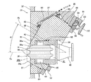
[도1] 본 발명에 관한 실드 굴진기의 비트교환유닛의 실시예1을 나타내고, 비트교환유닛의 종단면도이다.
[도2] 커터헤드의 굴삭 개구부를 나타내는 정면도이다.
[도3] 비트교환유닛의 주요부를 확대한 밸브체의 종단면도이다.
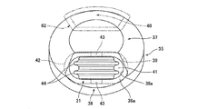
[도4] 밸브체의 정면도이다.
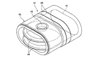
[도5] 롤러비트 및 비트 지지체를 나타내는 사시도이다.
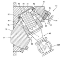
[도6] 비트교환유닛에 있어서의 교환동작을 설명하는 종단면도이다.
[도7] 도6의 부분 확대도이다.
[도8] 도6의 정면도이다.
[도9] 비트교환유닛에 있어서의 교환동작을 설명하는 종단면도이다.
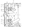
[도10] 비트교환유닛을 구비한 실드 굴진기의 종단면도이다.
[도11] 비트교환유닛을 구비한 실드 굴진기의 커터헤드를 나타내는 정면도이다.1 shows a first embodiment of a bit exchange unit of a shield excavator according to the present invention, and is a longitudinal cross-sectional view of the bit exchange unit.
Fig. 2 is a front view showing the excavation opening of the cutter head.
Fig. 3 is a longitudinal sectional view of the valve body in which the main part of the bit exchange unit is enlarged.
4 is a front view of the valve body.
Fig. 5 is a perspective view showing the roller bit and the bit support.
Fig. 6 is a longitudinal sectional view for explaining an exchange operation in the bit exchange unit.
Fig. 7 is a partially enlarged view of Fig. 6.
Fig. 8 is a front view of Fig. 6.
Fig. 9 is a longitudinal sectional view for explaining an exchange operation in the bit exchange unit.
Fig. 10 is a longitudinal sectional view of a shield excavator with a bit change unit.
Fig. 11 is a front view showing a cutter head of a shield excavator equipped with a bit change unit.
[실시예1][Example 1]
이하, 본 발명에 관한 굴삭비트 교환장치(掘削bit 交換裝置)를 구비한 실드 굴진기(shield 掘進機)의 실시예를 도면에 의거하여 설명한다.EMBODIMENT OF THE INVENTION Hereinafter, the Example of the shield excavator provided with the excavation bit exchange apparatus which concerns on this invention is described based on drawing.
(실드 굴진기)(Shield tread)
도10에 나타나 있는 바와 같이 원통형의 실드 본체(shield 本體)(11)의 앞부분에는 압력분리벽(壓力分離壁)(12)이 설치된다. 이 압력분리벽(12)의 앞부분에는, 막장붕괴토압(coalface崩壞土壓)을 지지하는 압력실(壓力室)(28A)이 형성되어 있다. 상기 압력분리벽(12)에는, 선회 베어링(旋回 bearing)(13)을 통하여 선회 링체(旋回 ring體)(14)가 실드축심(shield軸心)(O)을 중심으로 회전하도록 지지되고, 이 선회 링체(14)로부터 전방(前方)으로 돌출된 복수의 지지다리(15)에 원형의 커터헤드(cutter head)(16)가 지지되어 있다.As shown in FIG. 10, a
압력분리벽(12)의 후방(後方)의 대기실(大氣室)(28B)에는, 커터헤드(16)를 회전하도록 구동하는 커터 구동장치(cutter 驅動裝置)(17)가 설치되어 있다. 이 커터 구동장치(17)는, 선회 링체(14)의 배면에 설치된 링기어(ring gear)(17a)와, 링기어(17a)와 맞물리는 복수의 구동 피니언(驅動 pinion)(17b)과, 상기 구동 피니언(17b)을 각각 회전하도록 구동하는 회전구동장치(유압식 또는 전동식모터)(17c)로 구성되어 있다. 또한 압력분리벽(12)에는 커터헤드(16)에 의하여 굴삭된 토사(土砂)를, 압력실(28A)에서 막장붕괴토압을 지지하면서 이 압력실(28A)로부터 대기실(28B)로 배출시키는 배토용 스크루 콘베이어(排土用 screw conveyor)(18)가 관통하여 설치되어 있다.In the
(커터헤드)(Cutter head)
커터헤드(16)는, 도11에 나타나 있는 바와 같이 실드축심(O)상에 배치된 중심부재(中心部材)(20)로부터 반경방향(半徑方向)으로 연장되는 복수의 주스포크(主spoke)(21)와, 주스포크(21) 사이에서 반경방향으로 연장되는 복수의 부스포크(副spoke)(22)와, 실드축심(O)을 중심으로 하는 원호방향(圓弧方向)으로 설치되어서 주스포크(21) 및 부스포크(22)를 연결하는 중간링(中間ring)(23) 및 외주링(外周ring)(24)을 구비한다. 그리고 부재(21∼24) 사이에 토사 유입구(土砂 流入口)(25)가 형성되어 있다.The
그리고 주스포크(21)의 앞부분에는, 본 발명에 관한 복수의 비트교환유닛(bit交換unit)(굴삭비트 교환장치)(30)이 설치된다. 각 비트교환유닛(30)에는, 교환용의 굴삭비트인 롤러비트(roller bit)(31)가 각각 설치되어 있다. 또한 중심부재(20) 및 부스포크(22)의 앞면 및 측면, 주스포크(21)의 측면에는, 복수의 고정비트(固定bit)(26)가 각각 설치되어 있다.In the front portion of the
도10에 나타나 있는 바와 같이 상기 중심부재(20)의 배면측에는, 작업원이 출입가능한 맨홀(manhole)(27)이 형성되어 있다. 이 맨홀(27)은, 압력분리벽(12)을 관통하여 대기실(28B)측으로부터 출입할 수 있도록 통하게 되어 있다. 또한 각 주스포크(21)의 배면측에는 작업원이 들어가서 비트교환작업이 가능한 작업공간(29)이 형성되어, 작업원이 맨홀(27)로부터 작업공간(29)으로 왕래할 수 있도록 통하게 되어 있다. 그 때문에 굴삭 도중에 맨홀(27)로부터 작업공간(29)으로 들어간 작업원에 의하여, 마모된 롤러비트(31)를 작업공간(29)에서 교환할 수 있다.As shown in FIG. 10, a
(비트교환유닛)(Bit exchange unit)
주스포크(21)의 앞면에는, 반경방향을 따라 비트교환유닛(30)이 소정의 피치(pitch)로 설치되어 있다. 이들 비트교환유닛(30)에 롤러비트(31)가 배치되어 있다. 이들 비트교환유닛(30)은 각각 동일한 구조이다.On the front face of the
롤러비트(31)는, 도5에 나타나 있는 바와 같이 전후방향으로 배니통로(排泥通路)(41)가 형성된 타원통형 단면(楕圓筒刑 斷面)의 비트 지지체(bit 支持體)(42)를 구비한다. 비트 지지체(42)의 앞부분에는, 단축지름방향의 지축(支軸)(43)을 통하여 날이 2매인 디스크 커터(disc cutter)(44)가 회전하도록 지지되어 있다.As shown in Fig. 5, the
도1∼도4에 나타나 있는 바와 같이 비트교환유닛(30)의 하우징(housing)(33)은, 주스포크(21)의 앞면판(32)의 절제부(切除部)에 부착되어 있다. 이들 하우징(33)은 롤러비트(31)가 노출되는 굴삭 개구부(掘削 開口部)(34)를 구비한다. 또 하우징(33)에는 밸브 수용실(valve 收容室)(36)이 형성되어 있다. 이 밸브 수용실(36)은 굴삭 개구부(34)와 통하게 된다. 그리고 밸브 수용실(36)은, 롤러비트(31)를 지지하는 밸브체(35)를 경사자세이고 또한 회전하도록 수용한다.As shown in Figs. 1 to 4, the
밸브체(35)는 대략 원기둥모양으로 형성되어 있다. 밸브체(35)의 앞쪽 가장자리 외주부에는, 굴삭 개구부(34)를 폐쇄가능한 밀봉체부(密封體部)(37)가 둘레방향을 따라 형성되어 있다. 밀봉체부(37)는, 예를 들면 엣지 부분(edge 部分)이 원기둥모양에 있어서 축심인 회전축심(Ob)에 대하여 소정의 각도(예를 들면 후술하는 α°)로 경사진 경사면으로 베벨링(beveling)된 사다리꼴 단면에 형성되어 있다. 밀봉체부(37)에는, 밀봉체부(37)의 일부를 절제해서 굴삭 오목부(38)가 형성되어 있다. 이 굴삭 오목부(38)에, 롤러비트(31)를 빼어낼 수 있게 수용하는 비트수용구멍(39)이 개구되어 있다. 도4에 나타나 있는 바와 같이 굴삭 오목부(38)의 저면(底面)은, 비트수용구멍(39)의 개구부의 주위가 회전축심(Ob)에 대하여 소정의 각도(후술하는 α°)로 경사지는 삭제평면(削除平面)(38a)에 형성된다. 상기 삭제평면(38a)과 밀봉체부(37)의 정상부(頂上部)의 회전궤적과의 사이에, 디스크 커터(44)의 굴삭단(掘削端)이 돌출되는 굴삭공간(38b)이 형성된다.The
또한 밸브 수용실(36)은, 밸브체(35)를 회전하도록 수용 가능한 대략 원기둥모양으로 형성되어 있다. 밸브 수용실(36)은, 굴삭 개구부(34)에서 상기 삭제평면(38a)이 하우징(33)의 앞면과 대략 하나의 면모양이 되도록, 그 축심(밸브체(35)의 회전축심(Ob))이 각도 α°로 경사져서 형성되어 있다. 또한 하우징(33)의 배면은, 회전축심(Ob)과 수직인 경사평면으로 삭제되어 있다. 이 경사평면에, 작업공간(29)과 면하여 밸브 수용실(36)이 개구된다.In addition, the
밸브 수용실(36)의 앞면부는, 밀봉체부(37)을 안내하는 원뿔대모양으로 형성된다. 밸브 수용실(36)의 하부(下部)는, 비트 지지체(42)와 닮은 모양으로 회전축심(Ob)의 접선방향을 따르는 타원형으로 형성된 굴삭 개구부(34)와 통하게 되어 있다. 또한 회전축심(Ob)에 대하여 굴삭 개구부(34)의 180° 대칭위치에, 비트교환시에 굴삭 오목부(38)가 대응되는 교환밀봉부(40)가 형성된다. 교환밀봉부(40)에는 후술하는 제2밀봉재(62)가 설치되어 있다. 또 교환밀봉부(40)는 180° 대칭위치에 한정되는 것은 아니고, 회전축심(Ob)을 중심으로 하여 굴삭 개구부(34)와 동일한 축심상이고 또한 굴삭 개구부(34)와 겹치지 않는 위치이면 좋다.The front part of the
(밸브회전장치)(Valve rotation device)
밸브 수용실(36)의 후부(後部)에는, 밸브체(35)가 회전축심(Ob)을 중심으로 하여 회전하도록 구동하는 밸브 회전장치(51)가 설치되어 있다. 밸브 회전장치(51)는, 밸브체(35)의 후단부 외주(後端部 外周)에 설치된 링기어(52)와, 하우징(33)의 후부에서 회전축심(Ob)과 평행한 축심을 중심으로 하여 회전하도록 지지된 구동축(53)과, 구동축(53)에 고정되어서 링기어(52)와 교합(咬合)되는 구동 피니언(54)과, 구동축(53)을 회전하도록 구동하는 수동핸들(55)로 구성되어 있다.In the rear part of the
(배니배관)(Banner piping)
롤러비트(31)의 배니통로(41)에는, 주스포크(21)의 배면에서 압력실(28A)과 통하는 배니배관(排泥配管)(45)이 접속되어 있다. 배니배관(45)은, 비트 지지체(42)와 테이퍼관(taper管)을 통하여 접속된 제1게이트 밸브(차단밸브)(46A)와, 제1게이트 밸브(46A)와 단관(短管)(47)을 통하여 접속된 제2게이트 밸브(차단밸브)(46B)와, 배면판(背面板)에 관통하여 설치된 배출관(排出管)(48)을 구비하고 있다. 배출관(48)은, 배니통로(41)로부터 축심(Oa)을 따라 직선모양으로 작업공간(29)을 관통하여 압력실(28A)로 개구되어 있다. 이렇게 배니배관(45)을 구성함으로써, 부서진 돌이 섞인 흙탕물을 폐쇄시키지 않고 원활하게 배출할 수 있다.A
(밀봉재)(Sealing material)
하우징(33)의 굴삭 개구부(34)의 내주면(內周面)에는, 밸브체(35)와의 간극(間隙)으로부터 흙탕물 혹은 토사 등의 침입을 방지하는 제1밀봉재(61)가 설치되어 있다. 제1밀봉재(61)는, 굴삭시에 굴삭 오목부(38)의 주위를 밀봉한다. 또한 교환밀봉부(40)에는, 밸브 수용실(36)의 내면에 교환밀봉부(40)까지 선회하여 이동한 굴삭 오목부(38)의 주위를 밀봉하는 제2밀봉재(교환용 밀봉재)(62)가 설치되어 있다. 제2밀봉재(62)는, 하우징(33)에 형성된 조압구멍(調壓hole)(63)이 접속된 중공상(中空狀)의 튜브모양 밀봉재에 의하여 구성된다. 이 제2밀봉재(62)는, 조압구멍(63)으로부터 중공부(中空部)로 공급 및 배출되는 가압유체(加壓流體)인 유압(油壓) 또는 가압 에어(加壓 air)에 의하여 신축되어서 밸브체(35)에 대한 슬라이딩 접촉압력을 조정할 수 있다. 이에 따라 비트교환시에 밸브체(35)가 회전될 때에, 제2밀봉재(62)를 감압(減壓)하여 수축시켜 둠으로써 굴삭 오목부(38)의 엣지 및 디스크 커터(44)의 굴삭단부가 통과할 때의 손상을 미연에 방지할 수 있다. 물론 제1밀봉재(61)를 가압, 감압이 가능한 튜브모양 밀봉재로 하여도 좋다.On the inner circumferential surface of the
밸브체(35)의 외주부에는, 밸브 수용실(36)의 내주면과 슬라이딩하는 제3밀봉재(64)가 설치되어 있다. 또한 비트 지지체(42)의 외주면에는, 비트수용구멍(39)의 내주면과 슬라이딩하는 제4밀봉재(65)가 설치되어 있다.In the outer peripheral portion of the
(롤러비트 교환방법)(Roller Bit Replacement)
상기 비트교환유닛(30)에 있어서의 굴삭비트 교환방법을 도1, 도6∼도9를 참조하여 설명한다.The excavation bit exchange method in the
소정의 거리의 터널을 굴삭해서 롤러비트(31)의 디스크 커터(44)가 마모되면, 교환하려는 비트교환유닛(30)을 구비하는 주스포크(21)가 대략 수평이 되는 자세에서 커터헤드(16)를 정지시킨다. 그리고 맨홀(27)로부터 작업공간(29)으로 작업원이 들어가서 비트의 교환작업을 한다.When the
A) 도1에 나타내는 굴삭상태로부터, 우선 제1게이트 밸브(46A) 및 제2게이트 밸브(46B)를 닫고, 배니배관(45)의 단관(47)을 분리시킨다.A) From the excavation state shown in FIG. 1, the
B) 도6∼도8에 나타나 있는 바와 같이 제2밀봉재(62)를 감압한 후에, 밸브 회전장치(51)의 수동핸들을 회전시켜서 밸브체(35)를 회전축심(Ob)을 중심으로 하여 180° 회전시켜, 굴삭 개구부(34)의 마모 롤러비트(31)를 교환밀봉부(40)까지 변위(變位)시킴과 아울러, 굴삭 개구부(34)를 밀봉체부(37)에 의하여 폐쇄한다.B) After depressurizing the second sealing
C) 도9에 나타나 있는 바와 같이 제2밀봉재(62)를 가압해서 삭제평면(38a)의 주위와 압접(壓接)시킨 후에, 또한 도면에 나타나 있지 않은 빼내기 치구를 사용하여 마모 디스크 커터(44)를 구비하는 롤러비트(31)를 비트수용구멍(39)으로부터 빼어낸다.C) As shown in Fig. 9, the second sealing
D) 빼내기 치구를 사용하여 새로운 롤러비트(31)를 비트수용구멍(39)에 장전(裝塡)한다.D) A
E) 제2밀봉재(62)를 감압한 후에, 밸브 회전장치(51)를 조작해서 밸브체(35)를 회전축심(Ob)을 중심으로 하여 180° 회전시켜, 교환밀봉부(40)에 있는 신규 롤러비트(31)를 회전해서 굴삭 개구부(34)에 대응시킨다. 또한 제1게이트 밸브(46A)와 제2게이트 밸브(46B) 사이에 단관(47)을 접속한다. 그리고 제1, 제2게이트 밸브(46A, 46B)를 열어서 배니배관(45)을 통하게 한다.E) After depressurizing the
상기 실시예에 의하면, 원기둥모양의 앞쪽 가장자리부 주위에 형성된 밀봉체부(37)의 일부에 굴삭 오목부(38)를 통하여 비트수용구멍(39)이 개구된 밸브체(35)를 설치하고, 이 밸브체(35)를, 커터헤드의 앞면에 설치한 하우징(33)의 밸브 수용실(36)에 커터헤드(16)의 앞면과 수직인 축(Oa)에 대하여 경사지는 회전축심(Ob)을 중심으로 하여 회전하도록 수용했기 때문에, 비트교환시에 밸브체(35)를 회전축심(Ob)을 중심으로 하여 회전시키는 것만으로, 마모 롤러비트(31)를 수용한 굴삭 오목부(38)를 제2밀봉재(62)로 둘러싸인 교환밀봉부(40)까지 변위시킴과 동시에, 밀봉체부(37)에 의하여 굴삭 개구부(34)를 폐쇄할 수 있으며, 교환밀봉부(40)의 마모 롤러비트(31)를 비트수용구멍(39)으로부터 빼어내어 새로운 롤러비트(31)를 장전하고, 그 후에 밸브체(35)를 회전해서 새로운 롤러비트(31)를 굴삭 개구부(34)에 대응시키는 것만으로, 용이하고 또한 짧은 시간에 마모 롤러비트(31)를 새로운 롤러비트(31)로 교환할 수 있다.According to this embodiment, the
또한 하우징(33)내에 밸브체(35)를 수용한 간단한 구조로 신뢰성이 높다. 또한 밸브체(35)를 원기둥모양으로 형성함으로써 구체(球體)와 비교하여 충분하게 큰 굴삭반력을, 밸브체(35) 및 하우징(33)을 통하여 확실하게 지지할 수 있다.Moreover, the simple structure which accommodated the
또한 제2밀봉재(62)를 슬라이딩 접촉압력이 조절 가능한 튜브 밀봉으로 했기 때문에, 교환시에 교환밀봉부(40)에 출입하는 롤러비트(31) 및 굴삭 오목부(38)가 통과할 때에 제2밀봉재(62)를 감압함으로써, 동반되는 토사 혹은 자갈에 의한 제2밀봉재(62)의 파손을 방지할 수 있으며, 밀봉성능을 향상시킬 수 있다.Moreover, since the
또한 비트 지지체(42)의 배니통로(41)로부터 직선모양으로 신장하는 배니배관(45)을 접속함으로써, 롤러비트(31)에 의하여 굴삭된 부서진 돌이 섞인 흙탕물을 폐쇄하지 않고 원활하게 압력실(28A)로 배출할 수 있어, 효과적으로 굴삭할 수 있다. 또한 배니배관(45)에서, 비트교환시에 분리되는 단관(47)의 전후에 제1, 제2게이트 밸브(46A, 46B)를 설치하였기 때문에, 비트교환시에 제1, 제2게이트 밸브(46A, 46B)를 닫아서 단관(47)을 분리함으로써, 흙탕물을 작업공간(29)으로 유입시키지 않고 배니배관(45)을 분리할 수 있어, 마모 롤러비트(31)의 교환을 짧은 시간에 용이하게 할 수 있다.
In addition, by connecting the
11 ; 실드 본체
12 ; 압력분리벽
13 ; 선회 베어링
14 ; 선회 링체
16 ; 커터헤드
17 ; 커터 구동장치
18 ; 배토용 스크루 콘베이어
20 ; 중심부재
21 ; 주스포크
22 ; 부스포크
25 ; 토사 유입구
26 ; 고정비트
27 ; 맨홀
29 ; 작업공간
30 ; 비트교환유닛
31 ; 롤러비트
33 ; 하우징
34 ; 굴삭 개구부
35 ; 밸브체
36 ; 밸브 수용실
37 ; 밀봉체부
38 ; 굴삭 오목부
39 ; 비트수용구멍
40 ; 교환밀봉부
41 ; 배니통로
42 ; 비트 지지체
44 ; 디스크 커터
45 ; 배니배관
46a, 46b ; 제1, 제2게이트 밸브
47 ; 단관
48 ; 배출관
51 ; 밸브 회전장치
54 ; 구동 피니언
55 ; 수동핸들
61 ; 제1밀봉재
62 ; 제2밀봉재
63 ; 조압구멍
64 ; 제3밀봉재
65 ; 제4밀봉재
O ; 실드축심
Oa ; 축
Ob ; 회전축심11; Shield body
12; Pressure separation wall
13; Slewing bearing
14; Slewing ring
16; Cutter head
17; Cutter Drive
18; Scraper conveyor for clay
20; Center member
21; Juice fork
22; Busspoke
25; Soil inlet
26; Fixed bit
27; manhole
29; Workspace
30; Bit exchange unit
31; Roller bit
33; housing
34; Excavation opening
35; Valve body
36; Valve accommodation
37; Seal body part
38; Excavation recess
39; Bit receiving hole
40; Exchange seal
41; Bany passage
42; Bit support
44; Disc cutter
45; BANNY PIPE
46a, 46b; 1st, 2nd gate valve
47; Short pipe
48; discharge pipe
51; Valve rotator
54; Driving pinion
55; Handwheel
61; First sealing material
62; Second sealing material
63; Pressure hole
64; Third sealing material
65; Fourth Sealing Material
O; Shield shaft
Oa; shaft
Ob; Rotary shaft
Claims (3)
상기 커터헤드의 앞면에 부착되어서 상기 굴삭비트가 노출되는 굴삭 개구부가 형성된 하우징(housing)과,
상기 하우징에 형성되어서 상기 굴삭 개구부가 통하는 밸브 수용실에, 상기 커터헤드의 앞면과 수직인 축에 대하여 소정의 각도로 경사지는 회전축심을 중심으로 하여 회전 가능하게 배치된 밸브체(valve體)와,
상기 밸브체에 상기 굴삭 개구부와 통할 수 있게 형성되어서 상기 굴삭비트를 삽탈(揷脫) 가능하게 수용하는 비트수용구멍과,
상기 밸브 수용실의 앞면에서, 상기 회전축심을 중심으로 하는 상기 굴삭 개구부의 회전위치에서 상기 굴삭 개구부로부터 이간(離間)하여 설치된 교환밀봉부(交換密封部)를
구비하고,
상기 밸브체를 대략 원기둥모양으로 형성함과 아울러,
상기 밸브체에,
앞쪽 가장자리 외주부를 따라 형성되어서 상기 굴삭 개구부를 폐쇄가능한 밀봉체부와,
상기 밀봉체부의 일부에 형성된 상기 비트수용구멍의 개구부와,
상기 비트수용구멍의 개구부의 주위에 상기 밀봉체부를 삭제하여 형성되어 상기 굴삭비트의 굴삭단(掘朔端)을 수용하는 굴삭 오목부를
형성하고,
상기 교환밀봉부의 주위에서 상기 하우징과 상기 밸브체의 간극(間隙)을 밀봉하는 교환용 밀봉재를 설치하고,
상기 굴삭비트의 교환시에, 상기 밸브체를 상기 회전축심을 중심으로 하여 회전시켜서 상기 굴삭 오목부의 상기 굴삭비트를 상기 교환밀봉부로 이동시키고, 상기 비트수용구멍으로부터 상기 굴삭비트를 빼어내어 교환하는
것을 특징으로 하는 실드 굴진기의 굴삭비트 교환장치.
Excavation bit change device of shield excavator for exchanging excavation bit arranged in front of cutter head in the work space formed in the cutter head during excavation as,
A housing attached to the front surface of the cutter head, the housing having an excavation opening to which the excavation bit is exposed;
A valve body formed in the housing and disposed in the valve accommodation chamber through which the excavation opening passes, the valve body being rotatable about an axis of rotation inclined at a predetermined angle with respect to an axis perpendicular to the front face of the cutter head;
A bit accommodating hole formed in the valve body so as to communicate with the excavation opening portion, and accommodating the excavation bit in a detachable manner;
On the front face of the valve accommodation chamber, an exchange sealing portion provided spaced apart from the excavation opening portion at a rotational position of the excavation opening portion centered on the rotary shaft center is provided.
Respectively,
In addition to forming the valve body in a substantially cylindrical shape,
To the valve body,
A seal portion formed along a front edge outer circumference thereof to close the excavation opening;
An opening of the bit receiving hole formed in a part of the sealing member;
Excavation recessed part formed around the opening part of the said bit accommodation hole by removing the said sealing body part, and accommodating the excavation end of the said excavation bit.
Forming,
An exchange sealant for sealing a gap between the housing and the valve body around the exchange seal;
At the time of exchanging the excavation bit, the valve body is rotated about the rotation axis to move the excavation bit of the excavation recess to the exchange sealing part, and the excavation bit is removed from the bit receiving hole and replaced.
Excavation bit exchange device of the shield excavator, characterized in that.
상기 교환용 밀봉재를, 그 중공부(中空部)에 공급된 유체압력을 변화시켜서 슬라이딩 접촉압력이 조정 가능한 튜브모양 밀봉재로 하는
것을 특징으로 하는 실드 굴진기의 굴삭비트 교환장치.
The method of claim 1,
The replacement sealing material is a tube-shaped sealing material in which the sliding contact pressure is adjustable by changing the fluid pressure supplied to the hollow part.
Excavation bit exchange device of the shield excavator, characterized in that.
상기 굴삭비트를, 비트 지지체(bit 支持體)에 디스크 커터(disc cutter)가 회전하도록 지지된 롤러비트(roller bit)로 하고,
상기 비트 지지체에, 상기 디스크 커터의 주위로부터 상기 비트수용구멍에 있어서 진출 및 후퇴방향을 따르는 배니통로(排泥通路)를 관통(貫通)하여 형성하고,
상기 비트 지지체의 상기 배니통로로부터 상기 작업공간을 통하여 상기 커터헤드의 외면(外面)과 통하는 직선모양의 배니배관(排泥配管)을 접속하고,
상기 배니배관과 접속 및 분리가능한 단관(短管)을 설치함과 아울러, 상기 단관의 입구측 및 출구측의 배관에 차단밸브를 각각 설치한
것을 특징으로 하는 실드 굴진기의 굴삭비트 교환장치.3. The method according to claim 1 or 2,
The excavation bit is a roller bit supported by a disc cutter to rotate on a bit support,
The bit support body is formed by passing through a vane path along the advancing and retracting direction in the bit receiving hole from the periphery of the disc cutter,
A line-shaped vane pipe communicating with the outer surface of the cutter head is connected from the vane passage of the bit support via the working space,
A single pipe is provided which can be connected to and disconnected from the vane pipe, and a shutoff valve is provided in each of the pipes on the inlet and outlet sides of the pipe.
Excavation bit exchange device of the shield excavator, characterized in that.
Applications Claiming Priority (3)
| Application Number | Priority Date | Filing Date | Title |
|---|---|---|---|
| JP2011210027A JP5769567B2 (en) | 2011-09-27 | 2011-09-27 | Drilling bit changer for shield machine |
| JPJP-P-2011-210027 | 2011-09-27 | ||
| PCT/JP2012/071251 WO2013047025A1 (en) | 2011-09-27 | 2012-08-23 | Drill bit exchange device for shield tunneling machine |
Publications (2)
| Publication Number | Publication Date |
|---|---|
| KR20140050112A true KR20140050112A (en) | 2014-04-28 |
| KR101547185B1 KR101547185B1 (en) | 2015-08-25 |
Family
ID=47995075
Family Applications (1)
| Application Number | Title | Priority Date | Filing Date |
|---|---|---|---|
| KR1020147007342A KR101547185B1 (en) | 2011-09-27 | 2012-08-23 | Drill bit exchange device for shield tunneling machine |
Country Status (7)
| Country | Link |
|---|---|
| US (1) | US9222356B2 (en) |
| JP (1) | JP5769567B2 (en) |
| KR (1) | KR101547185B1 (en) |
| CN (1) | CN103814190B (en) |
| HK (1) | HK1192770A1 (en) |
| SG (1) | SG11201400747SA (en) |
| WO (1) | WO2013047025A1 (en) |
Families Citing this family (10)
| Publication number | Priority date | Publication date | Assignee | Title |
|---|---|---|---|---|
| DE102014110310A1 (en) * | 2014-07-22 | 2016-01-28 | Herrenknecht Aktiengesellschaft | Cutting roller assembly and equipped with cutting roller assemblies cutting wheel |
| CN104912562B (en) * | 2015-06-30 | 2017-04-12 | 中铁一局集团有限公司 | Construction method for deformation control over existing operation tunnel crossing under shield |
| CN105855849B (en) * | 2016-04-14 | 2017-12-01 | 东北大学 | A kind of shield machine list hobboing cutter tool-changing mechanical arm |
| CN106499401B (en) * | 2016-12-19 | 2019-04-05 | 中交隧道工程局有限公司 | A kind of super-large-diameter shield machine normal pressure tool changing device and method |
| CN106593461B (en) * | 2017-02-14 | 2018-06-26 | 东北大学 | The girff mechanism and its application method of a kind of shield machine disk cutter |
| CN107747489A (en) * | 2017-11-16 | 2018-03-02 | 河北工业大学 | Automatic switching control equipment for shield machine work hobboing cutter and standby hobboing cutter |
| CN107829752A (en) * | 2017-12-12 | 2018-03-23 | 天津大学 | Adaptability tool changing device for the compound cutterhead of shield machine |
| CN108194093B (en) * | 2018-02-11 | 2020-04-24 | 湖北鸣利来冶金机械股份有限公司 | Cutter head of multi-cutter-head tricone bit push bench |
| JP6965201B2 (en) * | 2018-04-16 | 2021-11-10 | Jimテクノロジー株式会社 | Tunnel excavator |
| CN113605911B (en) * | 2021-08-30 | 2024-02-02 | 中国铁建重工集团股份有限公司 | Cutter head assembly, tunneling equipment and tunneling construction method |
Family Cites Families (18)
| Publication number | Priority date | Publication date | Assignee | Title |
|---|---|---|---|---|
| JPH04163965A (en) | 1990-10-29 | 1992-06-09 | Fujitsu Ltd | Manufacture of semiconductor device |
| JP3164793B2 (en) | 1998-04-28 | 2001-05-08 | 鹿島建設株式会社 | Support structure for various equipment in tunnel machine |
| JP3139749B2 (en) * | 1998-09-18 | 2001-03-05 | 川崎重工業株式会社 | Cutter equipment for shield machine |
| SG102583A1 (en) * | 1999-07-14 | 2004-03-26 | Mitsubishi Heavy Ind Ltd | Method for replacing cutters of tunnel-excavating machine, method for excavating tunnel, and tunnel-excavating machine |
| JP2001129353A (en) | 1999-11-01 | 2001-05-15 | Babcock Hitachi Kk | Gas flow path switching method for exhaust gas treatment apparatus |
| JP3692267B2 (en) * | 1999-12-15 | 2005-09-07 | 三菱重工業株式会社 | Cutter head |
| JP2002147175A (en) * | 2000-11-16 | 2002-05-22 | Mitsubishi Heavy Ind Ltd | Tunnel excavator and cutter replacing method |
| JP4166959B2 (en) | 2001-03-16 | 2008-10-15 | 株式会社小松製作所 | Cutter head of shield machine |
| TWI221501B (en) * | 2001-07-23 | 2004-10-01 | Taisei Corp | Shield tunneling method and shield tunneling machine |
| JP4163965B2 (en) | 2003-01-08 | 2008-10-08 | 三菱重工地中建機株式会社 | Tunnel excavator |
| JP4498227B2 (en) | 2005-06-17 | 2010-07-07 | 日立造船株式会社 | Bit exchanging device for shield machine |
| JP4150822B2 (en) | 2005-12-19 | 2008-09-17 | 東京都下水道サービス株式会社 | Excavation method and excavation apparatus |
| JP5058218B2 (en) * | 2009-06-26 | 2012-10-24 | 日立造船株式会社 | Excavator bit changer |
| CA2785364C (en) * | 2009-12-22 | 2017-08-22 | Bouygues Travaux Publics | Method for replacing a tunnel boring machine disk cutter, handling device and disk cutter suited to such a method |
| JP5355439B2 (en) * | 2010-01-29 | 2013-11-27 | 日立造船株式会社 | Excavator bit changer |
| CN201705361U (en) | 2010-04-14 | 2011-01-12 | 北京华隧通掘进装备有限公司 | Replaceable pilot cutter mounting device for shield machine |
| CN201747380U (en) | 2010-09-10 | 2011-02-16 | 中铁隧道装备制造有限公司 | Shield and TBM cutter head new wedge-shaped installation cutter rest |
| JP5889645B2 (en) * | 2012-01-24 | 2016-03-22 | 日立造船株式会社 | Bit exchanging method and apparatus for shield machine |
-
2011
- 2011-09-27 JP JP2011210027A patent/JP5769567B2/en not_active Expired - Fee Related
-
2012
- 2012-08-23 CN CN201280045339.2A patent/CN103814190B/en not_active Expired - Fee Related
- 2012-08-23 KR KR1020147007342A patent/KR101547185B1/en active IP Right Grant
- 2012-08-23 WO PCT/JP2012/071251 patent/WO2013047025A1/en active Application Filing
- 2012-08-23 US US14/347,007 patent/US9222356B2/en not_active Expired - Fee Related
- 2012-08-23 SG SG11201400747SA patent/SG11201400747SA/en unknown
-
2014
- 2014-06-20 HK HK14105940.4A patent/HK1192770A1/en not_active IP Right Cessation
Also Published As
| Publication number | Publication date |
|---|---|
| CN103814190A (en) | 2014-05-21 |
| JP2013072181A (en) | 2013-04-22 |
| HK1192770A1 (en) | 2014-08-29 |
| CN103814190B (en) | 2015-09-23 |
| JP5769567B2 (en) | 2015-08-26 |
| SG11201400747SA (en) | 2014-10-30 |
| US20140217805A1 (en) | 2014-08-07 |
| KR101547185B1 (en) | 2015-08-25 |
| WO2013047025A1 (en) | 2013-04-04 |
| US9222356B2 (en) | 2015-12-29 |
Similar Documents
| Publication | Publication Date | Title |
|---|---|---|
| KR20140050112A (en) | Drill bit exchange device for shield tunneling machine | |
| JP5889645B2 (en) | Bit exchanging method and apparatus for shield machine | |
| JP5843597B2 (en) | Disc head cutter exchanging apparatus and method for cutter head | |
| KR101680553B1 (en) | Bit-replacing device for excavator | |
| JP6650697B2 (en) | Tunnel excavator | |
| JP6633732B1 (en) | Drilling tool changer and tunnel machine | |
| KR20150118845A (en) | Earth and sand removal device for auger drill | |
| KR101980390B1 (en) | Boring equipment | |
| JP5730163B2 (en) | Excavation bit exchanging device and excavation bit exchanging method for shield machine | |
| JP2012132282A (en) | Disk cutter exchanger and tunnel excavator including the same | |
| JP6479892B2 (en) | Cutting crushing system, cutting crushing method, reconstruction promotion method | |
| JP6470077B2 (en) | Cutting bit mounting structure of tunnel machine | |
| JP5426271B2 (en) | Cutter maintenance device for shield machine | |
| JP3396026B2 (en) | Shield machine cutter disk | |
| JP7307664B2 (en) | Cutter bit changer for tunnel boring machine | |
| JP2003336485A (en) | Shield machine | |
| JP6804067B2 (en) | Tunnel boring machine | |
| JP4138626B2 (en) | Tunnel excavator and cutter exchanging method for tunnel excavator | |
| JP2018009322A (en) | Shield construction method with upward irregular cross section | |
| JP2023091511A (en) | tunnel excavator | |
| JP2022171334A (en) | Drilling tool exchanging device and tunnel excavator | |
| CN114412493A (en) | Push bench for hydraulic engineering | |
| NO176533B (en) | Method and apparatus for replacing an existing pipeline |
Legal Events
| Date | Code | Title | Description |
|---|---|---|---|
| A201 | Request for examination | ||
| E902 | Notification of reason for refusal | ||
| E701 | Decision to grant or registration of patent right | ||
| GRNT | Written decision to grant | ||
| FPAY | Annual fee payment |
Payment date: 20180806 Year of fee payment: 4 |
|
| FPAY | Annual fee payment |
Payment date: 20190718 Year of fee payment: 5 |