KR20130095153A - A removable prestressing steel pipe soil nailing structure - Google Patents
A removable prestressing steel pipe soil nailing structure Download PDFInfo
- Publication number
- KR20130095153A KR20130095153A KR1020120038009A KR20120038009A KR20130095153A KR 20130095153 A KR20130095153 A KR 20130095153A KR 1020120038009 A KR1020120038009 A KR 1020120038009A KR 20120038009 A KR20120038009 A KR 20120038009A KR 20130095153 A KR20130095153 A KR 20130095153A
- Authority
- KR
- South Korea
- Prior art keywords
- pipe
- steel pipe
- strand
- spiral steel
- removable
- Prior art date
Links
Images


Classifications
-
- E—FIXED CONSTRUCTIONS
- E02—HYDRAULIC ENGINEERING; FOUNDATIONS; SOIL SHIFTING
- E02D—FOUNDATIONS; EXCAVATIONS; EMBANKMENTS; UNDERGROUND OR UNDERWATER STRUCTURES
- E02D5/00—Bulkheads, piles, or other structural elements specially adapted to foundation engineering
- E02D5/74—Means for anchoring structural elements or bulkheads
- E02D5/80—Ground anchors
-
- E—FIXED CONSTRUCTIONS
- E02—HYDRAULIC ENGINEERING; FOUNDATIONS; SOIL SHIFTING
- E02D—FOUNDATIONS; EXCAVATIONS; EMBANKMENTS; UNDERGROUND OR UNDERWATER STRUCTURES
- E02D17/00—Excavations; Bordering of excavations; Making embankments
- E02D17/02—Foundation pits
- E02D17/04—Bordering surfacing or stiffening the sides of foundation pits
-
- E—FIXED CONSTRUCTIONS
- E02—HYDRAULIC ENGINEERING; FOUNDATIONS; SOIL SHIFTING
- E02D—FOUNDATIONS; EXCAVATIONS; EMBANKMENTS; UNDERGROUND OR UNDERWATER STRUCTURES
- E02D3/00—Improving or preserving soil or rock, e.g. preserving permafrost soil
- E02D3/12—Consolidating by placing solidifying or pore-filling substances in the soil
-
- E—FIXED CONSTRUCTIONS
- E02—HYDRAULIC ENGINEERING; FOUNDATIONS; SOIL SHIFTING
- E02D—FOUNDATIONS; EXCAVATIONS; EMBANKMENTS; UNDERGROUND OR UNDERWATER STRUCTURES
- E02D5/00—Bulkheads, piles, or other structural elements specially adapted to foundation engineering
- E02D5/22—Piles
- E02D5/62—Compacting the soil at the footing or in or along a casing by forcing cement or like material through tubes
-
- E—FIXED CONSTRUCTIONS
- E02—HYDRAULIC ENGINEERING; FOUNDATIONS; SOIL SHIFTING
- E02D—FOUNDATIONS; EXCAVATIONS; EMBANKMENTS; UNDERGROUND OR UNDERWATER STRUCTURES
- E02D2200/00—Geometrical or physical properties
- E02D2200/16—Shapes
- E02D2200/1671—Shapes helical or spiral
-
- E—FIXED CONSTRUCTIONS
- E02—HYDRAULIC ENGINEERING; FOUNDATIONS; SOIL SHIFTING
- E02D—FOUNDATIONS; EXCAVATIONS; EMBANKMENTS; UNDERGROUND OR UNDERWATER STRUCTURES
- E02D2200/00—Geometrical or physical properties
- E02D2200/16—Shapes
- E02D2200/1685—Shapes cylindrical
-
- E—FIXED CONSTRUCTIONS
- E02—HYDRAULIC ENGINEERING; FOUNDATIONS; SOIL SHIFTING
- E02D—FOUNDATIONS; EXCAVATIONS; EMBANKMENTS; UNDERGROUND OR UNDERWATER STRUCTURES
- E02D2250/00—Production methods
- E02D2250/0046—Production methods using prestressing techniques
-
- E—FIXED CONSTRUCTIONS
- E02—HYDRAULIC ENGINEERING; FOUNDATIONS; SOIL SHIFTING
- E02D—FOUNDATIONS; EXCAVATIONS; EMBANKMENTS; UNDERGROUND OR UNDERWATER STRUCTURES
- E02D2300/00—Materials
- E02D2300/0004—Synthetics
- E02D2300/0006—Plastics
- E02D2300/0007—PVC
-
- E—FIXED CONSTRUCTIONS
- E02—HYDRAULIC ENGINEERING; FOUNDATIONS; SOIL SHIFTING
- E02D—FOUNDATIONS; EXCAVATIONS; EMBANKMENTS; UNDERGROUND OR UNDERWATER STRUCTURES
- E02D2300/00—Materials
- E02D2300/0004—Synthetics
- E02D2300/0006—Plastics
- E02D2300/0009—PE
-
- E—FIXED CONSTRUCTIONS
- E02—HYDRAULIC ENGINEERING; FOUNDATIONS; SOIL SHIFTING
- E02D—FOUNDATIONS; EXCAVATIONS; EMBANKMENTS; UNDERGROUND OR UNDERWATER STRUCTURES
- E02D2300/00—Materials
- E02D2300/0026—Metals
- E02D2300/0029—Steel; Iron
- E02D2300/0034—Steel; Iron in wire form
Abstract
Description
본 발명은 제거 가능한 프리스트레싱 강관 쏘일 네일링 구조에 관한 것으로서, 측벽의 적정 위치에 천공홀을 형성하여 나선형 강관 파이프를 삽입하고, 상기 천공홀 및 나선형 강관 파이프 사이의 공간에 시멘트밀크를 충진하여 그라우팅하고, 상기 측벽의 굴착면을 숏크리트로 타설하여 이루어지는 프리스트레싱 강관 쏘일 네일링 구조에 관한 것이며, 구체적으로는 복수의 강선 가닥으로 이루어지고 일단이 제거식 내하체와 연결되는 PC강연선과, 상기 PC강연선이 내부로 관통하며, 일단의 내측에 암나사부를 형성하여 상기 제거식 내하체의 나사산과 결합되는 나선형 강관 파이프와, 상기 나선형 강관 파이프 외면 전체를 감싸는 피복 파이프와, 상기 숏크리트 상에 부착되며, 상기 PC강연선, 나선형 강관 파이프 및 피복 파이프가 외부로 연장되도록 삽입구를 형성한 플레이트와, 상기 플레이트 상에 부착되며, 일단에 경사진 형태의 끼움부가 형성되고 타단의 중심에 상기 PC강연선이 관통하는 각파이프와, 상기 각파이프의 상단에 위치하는 절단용 파이프, 및 상기 절단용 파이프 끝단에서 외부로 연장되는 상기 PC강연선을 고정하는 웨지콘부를 포함하여 구성되는 프리스트레싱 강관 쏘일 네일링 구조에 대한 것이다.The present invention relates to a removable prestressed steel pipe saw nailing structure, which forms a perforated hole at a proper position of the sidewall to insert a spiral steel pipe pipe, and grouts by filling cement milk in the space between the perforated hole and the spiral steel pipe pipe. The present invention relates to a prestressing steel pipe saw nailing structure formed by pouring the excavation surface of the sidewall with shotcrete, and specifically, comprising a plurality of steel wire strands and one end of which is connected to a removable load-bearing body, and the PC steel strand is internally A spiral steel pipe connected to the inner end of the one end and coupled to the thread of the removable inner body; a sheathed pipe covering the entire outer surface of the spiral steel pipe; and the shotcrete attached to the shotcrete; Shovel to extend spiral steel pipe and cladding pipe outward A plate having an inlet formed thereon, the pipe being attached to the plate, and having an inclined fitting at one end thereof, an angle pipe through which the PC strand passes through the center of the other end, a cutting pipe positioned at an upper end of the angle pipe; And a wedge-con part for fixing the PC strand extending from the cutting pipe end to the outside.
일반적으로 터파기, 흙막이, 철도 및 도로 등에 인접한 자연 및 인공사면의 보강, 지하구조물 및 터널 등과 같은 토목 관련 건축물의 축조에 필요한 굴착 지보체계, 기존 옹벽의 보수 및 옹벽을 설치하는 공사에서, 그 굴착면이 붕괴하는 것을 방지하기 위해 흙막이 공사, 어스 앵커(earth anchor) 및 쏘일 네일링(soil nailing)의 세 가지 보강 공법이 주로 이용되고 있다.In general, the excavation support system required for the construction of civil engineering-related buildings such as reinforcement of natural and artificial slopes, construction of underground structures and tunnels adjacent to trenches, masonry, railways and roads, repair of existing retaining walls, and installation of retaining walls In order to prevent the collapse of the surface, three reinforcement methods are mainly used, namely, earthen construction, earth anchor and oil nailing.
상기 쏘일 네일링 공법은 토사에 천공을 하여 이형철근, 스틸바, 스틸파이프, 또는 대나무 등의 보강재를 넣고, 천공 내부를 시멘트밀크 등으로 충진하고 전면을 숏크리트(shotcrete)로 처리하여 보강된 토체를 일체화시켜서 보강되지 않은 지반과 구분시켜 외부적으로는 재래식 중력식 옹벽과 같은 형태를 이루는 방법이다.The sawing nailing method is a drilled in the soil and put the reinforcing materials such as deformed reinforcing steel, steel bar, steel pipe, or bamboo, and filled the interior of the punching with cement milk, etc. and treated the shotcrete on the front surface to reinforce the soil body It is a method of forming a shape like a conventional gravity retaining wall externally by distinguishing it from unreinforced ground.
이러한 쏘일 네일링 공법은 기본적으로 인장응력, 전단응력 및 휨 모멘트에 저항할 수 있는 보강재를 프리스트레싱(prestressing) 없이 비교적 촘촘한 간격으로 삽입하여 지반의 전체적인 전단 강도를 증대시키고 발생 변위를 가능한 억제하고, 또한 굴착공사 도중이나 완료 후에 예상되는 이완을 제한하게 하는 공법으로, 비교적 경량 장비를 사용하여 시공하기 때문에 저소음, 저진동의 굴착 공사를 수행할 수 있으며, 어스 앵커 공법에 비하여 보강영역을 위한 천공 깊이가 매우 짧아 인접 대지의 경계를 침범하는데 따른 분쟁 발생의 감소 및 도심지 공사에 매우 유리하다.This saw nailing method basically inserts reinforcements that can resist tensile stresses, shear stresses and bending moments at relatively tight intervals without prestressing, increasing the overall shear strength of the ground and restraining possible displacement. As a method to limit the relaxation expected during or after excavation, it is possible to perform excavation work with low noise and low vibration because it is constructed using relatively light weight equipment, and the drilling depth for reinforcement area is much lower than that of earth anchor method. It is short, which is very advantageous for the reduction of disputes caused by violating the border of adjacent land and the construction of downtown.
도 1은 종래의 쏘일 네일링 공법을 나타낸 것으로서, 그 시공과정을 간략히 살펴보면, 흙막이벽(1)의 지반 내에 하향 경사지게 깊게 구멍을 천공하고, 그 천공된 구멍 내로 이형철근인 보강용 네일(2)을 삽입한 후, 몰탈 등의 그라우트(grout)재를 주입 및 경화시켜 그라우트 고결체(3)를 형성한 후, 지상으로 노출된 이형철근인 보강용 네일(2)의 끝단을 지압판(4)과 고정너트(5) 등을 이용하여 흙막이벽(1)에 고정하는 작업을 통해 경사말뚝 형태의 쏘일 네일링 구조체를 형성하게 된다.1 shows a conventional saw nailing method, briefly examining the construction process, drills a hole deeply inclined downward in the ground of the retaining wall 1, and reinforcing nail (2) which is a rebar in the drilled hole. After inserting, the grout material such as mortar is injected and cured to form a grout solidified body 3, and then the end of the reinforcing
이와 같은 쏘일 네일링 구조체는 그라우트 고결체의 주변 마찰 저항과 삽입된 이형철근인 보강용 네일의 인발저항을 통해 굴착벽면의 방향, 즉 흙막이벽쪽으로 작용하는 토압에 대항하여 원지반의 강성을 키워줌으로써 자립지지가 될 수 있도록 하고 있다.Such a nailing structure is self-supporting by increasing the stiffness of the ground plate against the earth pressure acting toward the excavation wall surface, that is, the earth wall, through the frictional resistance of the grout consolidation and the pull-out resistance of the reinforced reinforcement nail inserted into the reinforcing bar. It helps to support it.
그러나, 상기 종래 공법에 의한 쏘일 네일링 구조체는 지중에 매설되는 보강용 네일이 인접 대지경계선을 침범하여 시공되는 것이 보통이어서 철근을 제거하지 않고 지중에 그대로 잔류시킬 경우 민원에 따른 분쟁과 협의에 따른 공기지연, 토지 점용료의 지불, 추후 인접지역 공사시 장애요인은 물론 부식으로 인한 환경오염을 야기되는 등의 문제점이 지적되고 있다.However, in the conventional nailing structure, the nail nailing structure is constructed by reinforcing nails embedded in the ground by invading adjacent land boundary lines, and thus, when the residual nails remain in the ground without removing rebars, the disputes and consultations according to the civil complaint Problems such as air delay, payment of land occupancy fee, obstacles in construction of neighboring areas and environmental pollution due to corrosion are pointed out.
따라서, 이러한 문제를 해결하기 위한 것으로서, 보강 레일의 설치 후 해체하여 탈거하기 위한 여러 가지 방안들이 제시되고 있는바, 예를 들면 국내등록특허공보 제0308379호(2003년 03월 11일 등록, 이하 종래기술1이라 함)같은 기술을 들 수 있다.Therefore, to solve this problem, various methods for dismantling and removing after installation of the reinforcing rail have been proposed, for example, Korean Patent Publication No. 0308379 (registered on March 11, 2003, hereinafter referred to as Technology 1).
상기 종래기술1은 회수가 용이한 해체 제거식 네일 장치에 관한 것으로, 하단부측으로 숫나사부를 갖는 네일과, 중앙으로 천공된 홀 내주면으로 상기 네일의 숫나사부와 나사결합되기 위한 암나사부를 형성하고, 상부로 연장 돌출되는 결합구의 외주면으로 숫나사부를 갖는 앵커몸체부와, 중앙으로 내주면이 절곡 형성되며 관통되는 통공 하단측 내주면으로 암나사부가 형성되며 그 상부측으로 패킹을 개재하기 위한 단턱이 형성되는 앵커커버체로 되는 앵커체와, 하단부가 상기 앵커커버체 상면과 실링처리되며 상기 네일 외주면을 커버하여 끼워지기 위한 제1관체와, 상기 제1관체 외측으로 이격되며 끼워지는 제2관체로 구성된다.The prior art 1 relates to a dismantlement-removable nail device that is easy to recover, and forms a nail having a male screw portion at the lower end side and a female screw portion for screwing with the male screw portion of the nail at the inner circumferential surface of the hole. Anchor body having an anchor body having a male screw portion as an outer circumferential surface of an extension protrusion and an inner circumferential surface bent to the center and a female screw portion formed at an inner circumferential surface of a lower through-hole, and an anchor cover body having a step for interposing a packing to an upper side thereof. A sieve, a lower end portion is sealed with an upper surface of the anchor cover body, and includes a first tube body fitted to cover the nail outer circumferential surface and a second tube body spaced apart from the first tube body.
그러나, 종래기술1은 네일 자체가 요홈이 형성된 철근으로 이루어져 제거가 용이하지 않고, 또한 이를 위한 작업공간 및 도구가 따로 필요하므로 협소한 지역에서는 제거작업이 어려우며, 각종 환경에 따른 물리적 특성의 변화 때문에 다양한 하중에 대한 저항성에 유동적이지 못하고 네일 재질에 따른 한계적 특성으로 인해 시공 적용에 매우 제한적이다.However, the prior art 1 is not easy to remove because the nail itself is made of grooves formed with grooves, and also requires a separate work space and tools for the removal of the nail in a narrow area, due to changes in the physical characteristics according to various environments Due to its inflexibility in resistance to various loads and its limited characteristics depending on the nail material, it is very limited in application.
본 발명은 상술한 종래기술의 문제점을 해결하기 위한 것으로, 프리스트레싱 공법을 적용함으로써, 굴착 면의 변위를 억제하고, 지반의 침하나 토사의 유실방지 등과 같은 안정성을 제고할 수 있는 제거 가능한 프리스트레싱 강관 쏘일 네일링 구조를 제공하기 위한 것이다.The present invention is to solve the problems of the prior art described above, by applying the prestressing method, removable prestressing steel pipe saw that can suppress the displacement of the excavation surface, and improve the stability, such as preventing the settlement of soil or loss of soil, etc. To provide a nailing structure.
또한, 본 발명은 시공장비가 간단하므로 비탈면이나 주거공간이 밀집된 협소한 현장 등 시공 여건에 관계없이 쉽게 적용할 수 있고, 앵커 공법에 비해 네일부재의 길이가 짧고 고정 정착시키는 구조가 아니므로 이웃 지구의 경계를 침범할 우려가 적을 뿐만 아니라, 네일부재의 제거가 용이하므로 상호 분쟁의 소지를 없앨 수 있는 제거 가능한 프리스트레싱 강관 쏘일 네일링 구조를 제공하기 위한 것이다.In addition, the present invention can be easily applied regardless of the construction conditions, such as the narrow slopes and narrow site of the dwelling space because the construction equipment is simple, and the length of the nail member is short and fixed compared to the anchoring method of the neighboring districts The present invention is to provide a removable prestressed steel pipe saw nailing structure that can reduce the possibility of mutual disputes because the nail member is easy to remove as well as there is little fear of violating the boundary.
상기와 같은 과제를 해결하기 위한 본 발명의 프리스트레싱 강관 쏘일 네일링 구조는, 복수의 강선 가닥으로 이루어지고 일단이 제거식 내하체와 연결되는 PC강연선과, 상기 PC강연선이 내부로 관통하며, 일단의 내측에 암나사부를 형성하여 상기 제거식 내하체의 나사산과 결합되는 나선형 강관 파이프와, 상기 나선형 강관 파이프 외면 전체를 감싸는 피복 파이프와, 상기 숏크리트 상에 부착되며, 상기 PC강연선, 나선형 강관 파이프 및 피복 파이프가 외부로 연장되도록 삽입구를 형성한 플레이트와, 상기 플레이트 상에 부착되며, 일단에 경사진 형태의 끼움부가 형성되고 타단의 중심에 상기 PC강연선이 관통하는 각파이프와, 상기 각파이프의 상단에 위치하는 절단용 파이프, 및 상기 절단용 파이프 끝단에서 외부로 연장되는 상기 PC강연선을 고정하는 웨지콘부를 포함하여 구성되는 것을 특징으로 한다.The prestressing steel pipe saw nailing structure of the present invention for solving the above problems is made of a plurality of strands of wire and one end of the PC strand is connected to the removable inner body, and the PC strand is penetrated inside, Spiral steel pipe pipes are formed inside the female threaded portion coupled to the thread of the removable inner body, sheathed pipes covering the entire outer surface of the spiral steel pipes, attached to the shotcrete, and the PC stranded wire, spiral steel pipes and sheathed pipes. A plate having an insertion hole formed therein so as to extend outwardly, the plate being attached to the plate, the fitting portion having an inclined shape formed at one end thereof, and the PC strand extending through the center of the other end thereof, and positioned at an upper end of the angle pipe. To cut the pipe, and the PC strands extending outward from the end of the pipe for cutting Wedge cone is characterized in that comprises section.
본 발명의 제거 가능한 프리스트레싱 강관 쏘일 네일링 구조에 의하면, 프리스트레싱이 가능한 다발형태로 이루어진 복수의 강선을 채택함으로써, 굴착 면의 변위를 억제하는 것은 물론, 지반의 침하나 토사의 유실 등을 방지하는 안정성을 제고하는 효과가 뛰어나다.According to the removable prestressing steel pipe saw nailing structure of the present invention, by adopting a plurality of steel wires in the form of bundles capable of prestressing, it is possible to suppress the displacement of the excavated surface, as well as to prevent the settlement of soil or loss of soil. Excellent effect to uplift.
또한, 본 발명은 시공장비가 간단하므로 비탈면이나 주거공간이 밀집된 협소한 현장 등 시공 여건에 관계없이 쉽게 적용할 수 있고, 앵커 공법에 비해 네일부재가 고정된 구조가 아니며, 네일부재의 제거가 용이할 뿐만 아니라, 이웃 지구의 경계침범 등으로 인한 상호 분쟁의 소지를 없애는 등의 효과가 있다.In addition, the present invention can be easily applied regardless of the construction conditions, such as narrow slopes and dense sites dwelling because the construction equipment is simple, the structure is not fixed to the nail member compared to the anchor method, it is easy to remove the nail member In addition, it has the effect of eliminating the possibility of mutual disputes caused by violating the borders of neighboring districts.
아울러, 강성이 강한 나선형 강관 파이프와 PC강연선을 이용함으로써, 더욱 견고하게 지반을 지지할 수 있고, 네일부재 제거시에는 PC강연선, 나선형 강관 파이프 등을 제거할 수 있기 때문에, 자재 절약 및 회수 후의 재활용에도 도움이 된다.In addition, by using a rigid spiral steel pipe and PC stranded wire, it is possible to support the ground more firmly, and when removing the nail member, PC stranded wire and spiral steel pipe pipe can be removed. Also helps.
도 1은 종래의 네일 공법에 의한 네일 앵커의 개략적인 구조를 도시한 구성도이다.
도 2는 본 발명의 바람직한 실시 형태에 따른 프리스트레싱 강관 쏘일 네일링 구조의 전체 구성을 도시한 도면이다.
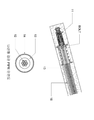
도 3은 도 2에서 나타낸 제거식 내하체(11)에 연결되는 PC강연선(12) 및 나선형 강관 파이프(13)의 구성을 확대 도시한 단면도이다.
도 4는 각파이프(18)의 구성을 도시한 단면도이다.
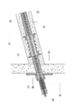
도 5는 본 발명에 따라 시공이 완료된 프리스트레싱 강관 쏘일 네일링 구조 및 및 숏크리트 결합을 나타낸 단면도이다.
도 6은 본 발명의 고정자 소켓(15) 및 플레이트(17)의 개략 구성을 도시한 도면이다.1 is a block diagram showing a schematic structure of a nail anchor according to a conventional nail method.
2 is a view showing the overall configuration of a prestressed steel pipe saw nailing structure according to a preferred embodiment of the present invention.
FIG. 3 is an enlarged cross-sectional view of the configuration of the
4 is a cross-sectional view showing the configuration of the
Figure 5 is a cross-sectional view showing the prestressing steel pipe saw nailing structure and shotcrete coupling completed in accordance with the present invention.
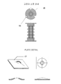
6 is a diagram showing a schematic configuration of the
이하, 본 발명에 따른 구성 및 작용효과를 첨부된 도면을 참조하여 상세하게 설명한다.Hereinafter, the configuration and effect according to the present invention will be described in detail with reference to the accompanying drawings.
여기서, 이하에 기술하는 실시예를 통하여 설명되는 내용은 본 발명을 실시하기 위한 하나의 실시예일 뿐이며, 본 발명은 이하에 기재된 실시예의 내용으로 한정되지 않는다.Here, the content described through the embodiments described below is only one embodiment for carrying out the present invention, the present invention is not limited to the contents of the embodiments described below.
도 1은 상기 설명에서 기술한 종래의 네일 공법에 의한 네일 앵커의 개략적인 구조를 도시한 구성도로서, 도 1에서 나타난 바와 같이, 흙막이벽(1)의 지반 내에 하향 경사지게 깊게 구멍을 천공하고, 그 천공된 구멍 내로 이형철근인 보강용 네일(2)을 삽입한 후, 몰탈 등의 그라우트(grout)재를 주입 및 경화시켜 그라우트 고결체(3)를 형성한 후, 지상으로 노출된 이형철근인 보강용 네일(2)의 끝단을 지압판(4)과 고정너트(5) 등을 이용하여 흙막이벽(1)에 고정하는 작업을 통해 이루어지는 쏘일 네일링 형태의 구성이다.1 is a configuration diagram showing a schematic structure of a nail anchor according to the conventional nail method described in the above description, as shown in Figure 1, to drill a hole deeply inclined downward in the ground of the retaining wall (1), After inserting the reinforcing nail (2), which is a rebar, into the perforated hole, the grout material such as mortar is injected and cured to form a grout solidified body (3), and then the rebar is exposed to the ground. The end of the reinforcing nail (2) is a configuration of the saw nailing made through the operation of fixing to the retaining wall (1) using the pressure plate (4) and the fixing nut (5).
도 2는 본 발명의 실시예에 따라 구성된 제거 가능한 프리스트레싱 강관 쏘일 네일링 구조를 개략적으로 도시한 도면이다.2 is a schematic illustration of a removable prestressing steel pipe saw nailing structure constructed in accordance with an embodiment of the present invention.
도 2에 나타낸 바와 같이, 본 발명에 따른 프리스트레싱 강관 쏘일 네일링 구조는 굴착된 천공홀 내에 시멘트밀크를 충진하여 천공홀 그라우팅(22)을 형성하고, 그 내부에 제거식 내하체(11), PC강연선(12), 나선형 강관 파이프(13), 및 피복 파이프(14)의 조립체를 삽입함으로써 이루어진다.As shown in FIG. 2, the prestressing steel pipe saw nailing structure according to the present invention fills cement milk in an excavated boring hole to form a boring hole grouting 22, and has a removable
상기 피복 파이프(14) 외부에는 고정자 소켓(15)을 복수로 구성하여, 천공홀 내부로 인입된 구조물들의 일탈을 방지하고 올바른 위치에 안착할 수 있도록 하며, 또한 고정자 소켓(15)의 외주면에 그라우팅 호스(16)를 연결할 수 있는 연결공을 형성하여 그라우팅 호스(16)가 천공홀 밑 부근까지 연장될 수 있도록 하여 그라우팅 주입 작업이 용이하게 이루어질 수 있도록 한다.A plurality of
또한, 상기 천공홀의 지반 또는 측벽의 외부는 숏크리트(shotcrete)(21)를 타설하여 경사면의 흙 또는 암석의 무너짐을 예방하고 안정적으로 유지할 수 있도록 하며, 이 숏크리트(21) 외부에는 플레이트(17) 및 각파이프(18)을 구성하여 천공홀로부터 연장되는 나선형 강관 파이프(13) 및 PC강연선(12)을 고정하고, 또한 PC강연선(12)의 최상단에는 웨지콘부(20)를 구성하여 PC강연선(12) 고정할 수 있도록 한다.In addition, the outside of the ground or sidewall of the perforation hole is to cast a shotcrete (21) to prevent and maintain the collapse of the soil or rock on the inclined surface, the
상기 각파이프(18) 및 웨지콘부(20) 사이에는 절단용 파이프(19)를 구성하여, 프리스트레싱 강관 쏘일 네일링 구조를 제거하는 경우 용이한 작업이 이루어질 수 있도록 한다.The
상기 웨지콘부(20)는 PC강연선(12)에 인장력을 부여하기 위한 구성이며, 상기 PC강연선(12)의 인장력으로 인한 반발력을 이용한 압축력을 상기 나선형 강관 파이프(13)에 부여할 수 있으며, 이 경우 웨지콘부(20)에 전달된 압축력은 상기 절단용 파이프(19) 및 각파이프(18)를 거쳐 상기 나선형 강관 파이프(13)로 가해지게 된다.The
즉, 상기 PC강연선(12)의 인장력과 더불어 나선형 강관 파이프(13)에 전해지는 압축력에 의해 발생되는 힘에 의해 상기의 구성들은 매우 강도가 높고 견고한 구성이 되며, 압축된 나선형 강관 파이프(13)의 힘의 변위가 천공홀 그라우팅(22) 주변의 지반 내부로 작용하여 지반으로부터의 인장응력을 상쇄시킬 수 있고, 또한 굴착면 부근의 변위가 이동하는 것을 억제한다.That is, by the force generated by the compressive force transmitted to the
도 3은 상기 도 2의 구성 중 PC강연선(12), 나선형 강관 파이프(13) 및 제거식 내하체(11)의 연결 구성을 도시한 도면으로서, 여기서 상기 PC강연선(12)은 복수의 강선이 다발형태로 엮어진 네일부재로, 끝단에 분리 가능한 제거식 내하체(11)가 연결되어 천공홀 그라우팅(22) 내부에 삽입되고, 또한 상기 제거식 내하체(11)는 천공홀 그라우팅(22) 내부에 삽입되는 나선형 강관 파이프(13)의 일단의 내주면에 형성된 암나사부와 나사결합되는 나사산을 형성하고 있다.3 is a view illustrating a connection configuration of the
상기 제거식 내하체(11)는 종래의 상용화된 또는 양산형의 제거식 내하체 등이 이용될 수 있으며, 예를 들면 국내공개특허공보 제10-2009-0039260호(2009년 04월 22일 공개, 이하 종래기술2)에서 기술하고 있는 정착부재의 구성을 이용할 수 있다.The removable
상기 종래기술2의 정착부재는 충진부재 내에 정착공간을 형성하는 외형캡, 외형캡의 입구에 나사결합된 콘플레이트, 콘플레이트의 경사면에 의해 네일부재의 한쪽 끝단을 결속시키는 복수의 콘, 외형캡 속에 나사결합되어 콘플레이트와 복수의 콘을 밀착시키며, 네일부재의 타격시 결합상태가 해지되게 하는 고정멈치 등으로 구성되어 있다.The fixing member of the
상기 종래기술2의 네일부재(본 발명의 PC강연선에 해당)는 소정의 타격을 가해지면, 정착부재의 정착력이 해지되면서 네일부재의 제거가 용이한 형태로 전환되는 것으로서, 네일부재의 타격시에는 소정의 타격력에 따라 네일부재가 휘어지거나 부서져 네일부재의 정착상태를 해지함으로써, 해체 작업 등의 경우에 필요에 의해 언제든지 제거 가능하도록 되어 있다.When the nail member (corresponding to the PC strand of the present invention) of the
그러나, 이는 본 발명의 제거식 내하체의 예로서 서술한 것이며, 본 발명은 상기 종래기술2와 같은 구성을 이용하거나, 또는 그와 유사한 다른 제거식의 내하체 구성 등이 당업자의 필요에 따라 선택적으로 이용될 수 있는 것으로서, 상술한 구성 내용에 제한되는 것은 아니다.However, this is described as an example of the removable load-bearing body of the present invention, and the present invention uses the same configuration as that of the
또한, 도 3에서는 나선형 강관 파이프(13)의 종단면을 도시하고 있는데, 앞서 설명한 PC강연선(12)이 중심에 위치하고, 반지름 방향으로 나선형 강관 파이프(13)가 위치하며, 상기 나선형 강관 파이프(13) 외부에는 피복 파이프(14)가 형성되어 있는 형태를 나타내고 있다.In addition, Figure 3 shows a longitudinal section of the
상기 나선형 강관 파이프(13)는 강관 외부에 나선형의 골을 형성한 형태로서, 외부에서 가해지는 하중 및 반발력이 관에 균등하게 분포되므로 일반적으로 축조 공사에 이용되는 구조용 강관 파이프보다 내하력이 우수한 특징이 있다.The
따라서, 높은 하중이 가해지는 프리스트레싱 강관 쏘일 네일링 구조에 매우 유리하며, 일반 강관 파이프나 PC강연선만으로 이루어지는 구조물 또는 도 1과 같은 철골 구조물의 구성보다 내하력이 우수하고 보다 경량으로 구성할 수 있는 장점이 있다.Therefore, it is very advantageous for the prestressing steel pipe saw nailing structure to which a high load is applied, and it has the advantage that the load capacity is excellent and can be made lighter than the structure which consists of the steel pipe structure or the structure which consists only of ordinary steel pipe pipes or PC strands only, such as FIG. have.
상기 나선형 강관 파이프(13) 바깥쪽 외면에는 피복 파이프(14)가 씌워진 형태이며, 상기 나선형 강관 파이프(13)의 일단에는 상기 제거식 내하체(11)와 나사결합되는 암나사부가 형성되어 있고, 프리스트레싱 강관 쏘일 네일링 구조를 철거하는 경우나 기타 다른 나선형 강관 파이프(13)의 분리가 필요한 경우에 용이하게 해제할 수 있다.The outer surface of the
상기 피복 파이프(14)는 합성수지 파이프, 예를 들면 폴리에틸렌(PE), 폴리에틸렌 테레프탈레이트(PET) 또는 폴리염화비닐(PVC) 재질의 파이프를 이용할 수 있으며, 프리스트레싱 강관 쏘일 네일링 구조를 제거하기 위해 상기 나선형 강관 파이프(13)를 수거할 때 표면 유격을 용이하게 하여 마찰 저항을 줄여 쉽게 분리할 수 있게 도와준다.The
다음으로 도 4를 참조하여, 각파이프(18)에 대해 설명한다.Next, with reference to FIG. 4, the
도 4에 나타나는 바와 같이, 상기 각파이프(18)는 매립되는 나선형 강관 파이프(13)를 숏크리트(21) 외부에 부착되는 플레이트(17)와 고정하기 위한 용도로서, 그 형태는 일반적인 캡(cap)의 형상이며, 나선형 강관 파이프(13)가 돌출되는 부분과 플레이트(17) 삽입구를 모두 커버할 수 있도록 일단에 경사진 형태의 끼움부가 형성되고(단면 A-A"), 타단의 중심에는 상기 PC강연선(12)이 관통할 수 있도록 통공이 형성되어 있다(단면 B-B").As shown in FIG. 4, the
즉, 각파이프(18)의 삽입구는 플레이트(17) 외부로 돌출된 나선형 강관 파이프(13) 및 피복 파이프(14)가 삽입되며, 나선형 강관 파이프(13) 내부에서 연장되는 PC강연선(12)은 상기 각파이프(18)의 중심홀을 통해 다시 외부로 연장되게 된다.That is, the insertion hole of the
앞에서 설명한 바와 같이 상기 각파이프(18)는 나선형 강관 파이프(13)를 플레이트(17)에 고정하는 용도인 동시에, 후술하는 웨지콘부(20) 및 PC강연선(12)에서 발생되는 인장력을 다시 상기 나선형 강관 파이프(13) 및 플레이트(17)로 전달하도록 하며, 이러한 인장력에 반발하는 힘(압축력)은 굴착 입구의 플레이트(17) 및 나선형 강관 파이프(13)를 가압 고정하는 역할을 한다.As described above, the
도 5는 본 발명에 따라 시공이 완료된 프리스트레싱 강관 쏘일 네일링 구조 상태와 각 구성의 결합을 확대 도시한 확대 단면도이다.Figure 5 is an enlarged cross-sectional view showing the expansion of the construction of the pre-stressed steel pipe saw nailing structure state and each configuration completed in accordance with the present invention.
도시된 바와 같이, 도 5에서는 천공홀 그라우팅(22) 내부로부터 숏크리트(21) 외부로 돌출한 프리스트레싱 강관 쏘일 네일링 구성들 중, 플레이트(17), 각파이프(18), 절단용 파이프(19), 및 웨지콘부(20) 등의 구성을 나타내고 있으며, 구체적으로는 천공홀 그라우팅(22) 반대 면의 숏크리트(21)에 나선형 강관 파이프(13)를 고정하면서 PC강연선(12), 나선형 강관 파이프(13) 및 피복 파이프(14)가 외부로 연장되도록 중간에 삽입구를 형성한 플레이트(17)와, 상기 나선형 강관 파이프(13)를 고정하기 위해 상기 플레이트(17) 상에 부착되고, 일단에 경사진 형태의 끼움부가 형성되고 중심에 상기 PC강연선(12)이 관통하는 각파이프(18)와, 상기 각파이프(18)의 상단에 위치하여 PC강연선(12)을 절단 또는 제거가 용이하도록 하기 위한 절단용 파이프(19), 및 상기 절단용 파이프(19) 끝단에서 외부로 연장되는 상기 PC강연선(12)을 고정 및 인장하도록 하는 웨지콘부(20) 등이 나타나 있다.As shown in FIG. 5, in the prestressed steel pipe saw nailing configurations projecting from the interior of the drill hole grouting 22 to the outside of the
상기 웨지콘부(20)는 종래의 상용화된 또는 양산형의 웨지콘부 등이 이용될 수 있으며, 예를 들면 상술한 종래기술2에서 나타내고 있는 고정부재의 구성을 이용할 수 있다.The
상기 종래기술2의 고정부재는 굴착공의 입구를 막는 커버플레이트와, 네일부재의 고정을 위한 복수형의 쐐기형 물림쇠와, 체결시 조임이 가능한 분리형 웨지가 형성된 설치고정편과, 설치고정편의 분리형 웨지에 나사결합되는 체결너트 등의 구성을 포함하고 있다.The fixing member of the
상기 종래기술2의 구성에 의하면, 설치고정편을 네일부재에 끼워 커버플레이트와 맞닿게 한 뒤, 설치고정편의 분리형 웨지에 체결너트를 조여 분리형 웨지 내부의 쇄기 물림쇠로부터 네일부재의 외면을 압착 고정하게 되어 있으며, 이와 같은 고정상태를 유지하여 강선 및 커버플레이트를 가압 고정하는 역할을 한다.According to the configuration of the
그러나, 이는 본 발명의 PC강연선(12)을 인장하도록 하는 웨지콘부(20)의 기능을 나타내기 위해 예시로서 서술한 것이며, 본 발명은 상기 종래기술과 같은 구성을 이용하거나, 또는 그와 유사한 다른 구성 등이 당업자의 필요에 따라 선택적으로 이용될 수 있는 것이며, 상기 구성으로 제한 또는 한정되는 것은 아니다.However, this is described by way of example to show the function of the
즉, 상기와 같은 기능의 웨지콘부(20)의 구성을 통해, PC강연선(12)를 인장함으로써 인장력을 얻게 되고, 이 인장력에 따른 반발력은 위지콘부(20) 및 절단용 파이프(19)로 전달되어 각파이프(18)을 밀어내는 압축력을 발생시키고, 각파이프(18)와 연결된 나선형 강관 파이프(13)와 플레이트(17)은 압축력을 받아 압축 강도가 높아지게 되므로, 숏크리트(21) 및 천공홀 그라우팅(22)의 지반이나 측벽에서 발생되는 외부 응력으로부터 더욱 견고하게 고정될 수 있게 되고 안정적인 보강 구조체를 형성할 수 있다.That is, through the configuration of the
도 5에 도시된 절단용 파이프(19)는 본 발명의 프리스트레싱 강관 쏘일 네일링 구조의 철거시나 부분적인 제거시 이용되는 것으로서, 예를 들면 이웃 지구를 경계를 침범하는 등의 문제 발생시 바로 쏘일 네일링 구조를 철거할 수 있도록 절단 위치를 표시하는 역할이며, 작업자는 이 철거시 절단용 파이프(19)의 위치를 파악한 후 작업하는 것이 가능하다.The cutting
도 6는 상기 도 1 내지 도 5에서 나타난 구성 중 고정자 소켓(15)와 플레이트(17)를 도시한 도면으로서, 도 6에 나타난 바와 같이, 상기 고정자 소켓(15)은 상하의 직경이 내부 직경보다 큰 대칭형의 원통으로 외부에는 그라우팅시 결속을 위한 돌기가 형성되고, 각 끝단의 외주면에 그라우팅 호스(16)를 끼우기 위한 연결공이 원주 방향을 따라 일정한 간격으로 형성되어 있다.FIG. 6 is a view illustrating the
또한, 플레이트(17)는 가운데가 숏크리트(21)의 바깥쪽 방향으로 돌출한 형태이며, 타원형의 돌출된 중심부에는 PC강연선(12), 나선형 강관 파이프(13) 및 피복 파이프(14)가 외부로 연장되는 삽입구가 형성되어 있다.In addition, the
이상, 본 발명을 실시하기 위한 바람직한 실시예에 따라 도면을 참조하여 설명하였다.It has been described above with reference to the drawings according to a preferred embodiment for practicing the present invention.
그러나 상기에서 설명한 프리스트레싱 강관 쏘일 네일링 구조는 상술한 실시예로 한정되지 아니하며, 특허청구범위에서 청구하는 본 발명의 요지를 벗어남이 없이 당해 발명이 속하는 기술 분야에서 통상의 지식을 가진 자라면 누구든지 다양한 변형 실시가 가능하다.However, the above-described prestressing steel pipe saw nailing structure is not limited to the above-described embodiment, and anyone having ordinary knowledge in the art to which the present invention pertains without departing from the gist of the present invention claimed in the claims. Various modifications are possible.
11. 제거식 내하체 12. PC강연선
13. 나선형 강관 파이프 14. 피복 파이프
15. 고정자 소켓 16. 그라우팅 호스
17. 플레이트 18. 각파이프
19. 절단용 파이프 20. 웨지콘(wedge cone)부
21. 숏크리트(shotcrete) 22. 천공홀 그라우팅11.
13. spiral
15.
17.
19. Cutting
21.
Claims (3)
복수의 강선 가닥으로 이루어지고 일단이 제거식 내하체와 연결되는 PC강연선과,
상기 PC강연선이 내부로 관통하며, 일단의 내측에 암나사부를 형성하여 상기 제거식 내하체의 나사산과 결합되는 나선형 강관 파이프와,
상기 나선형 강관 파이프 외면 전체를 감싸는 피복 파이프와,
상기 숏크리트 상에 부착되며, 상기 PC강연선, 나선형 강관 파이프 및 피복 파이프가 외부로 연장되도록 삽입구를 형성한 플레이트와,
상기 플레이트 상에 부착되며, 일단에 경사진 형태의 끼움부가 형성되고 타단의 중심에 상기 PC강연선이 관통하는 각파이프와,
상기 각파이프의 상단에 위치하는 절단용 파이프, 및 상기 절단용 파이프 끝단에서 외부로 연장되는 상기 PC강연선을 고정하는 웨지콘부를 포함하여 구성되는 것을 특징으로 하는 프리스트레싱 강관 쏘일 네일링 구조.Prestressed steel pipe sawing is formed by inserting a spiral steel pipe by forming a perforated hole at an appropriate position of the side wall, filling and grouting cement milk in the space between the perforated hole and the spiral steel pipe pipe, and casting the excavated surface of the side wall with shotcrete. In the nailing structure,
PC strand consisting of a plurality of strands of wire and one end connected to the removable inner body,
Spiral steel pipe pipe through which the PC strand is penetrated into the inside, and forms a female screw portion inside the one end and is coupled to the thread of the removable inner body;
A sheath pipe surrounding the entire outer surface of the spiral steel pipe pipe;
A plate attached to the shotcrete and formed with an insertion hole so that the PC stranded wire, the spiral steel pipe, and the coated pipe extend outwardly;
An angle pipe attached to the plate and having an inclined fitting portion formed at one end thereof and through which the PC strand wire passes through the center of the other end thereof;
Prestressing steel pipe saw nailing structure, characterized in that it comprises a cutting pipe located on the top of the pipe, and a wedge cone portion for fixing the PC strand extending from the cutting pipe end to the outside.
상기 천공홀 내부로 인입되는 상기 피복 파이프의 외부에는 복수의 고정자 소켓이 부착 형성되는 것을 특징으로 하는 프리스트레싱 강관 쏘일 네일링 구조.The method of claim 1,
Prestressing steel pipe saw nailing structure, characterized in that a plurality of stator sockets are attached to the outside of the coated pipe introduced into the drilling hole.
상기 피복 파이프는 폴리에틸렌(PE), 폴리에틸렌 테레프탈레이트(PET) 또는 폴리염화비닐(PVC) 재질의 합성수지 파이프인 것을 특징으로 하는 프리스트레싱 강관 쏘일 네일링 구조.The method of claim 1,
The coated pipe is a prestressed steel pipe saw nailing structure, characterized in that the plastic pipe made of polyethylene (PE), polyethylene terephthalate (PET) or polyvinyl chloride (PVC).
Applications Claiming Priority (2)
| Application Number | Priority Date | Filing Date | Title |
|---|---|---|---|
| KR1020120016516 | 2012-02-17 | ||
| KR20120016516 | 2012-02-17 |
Publications (2)
| Publication Number | Publication Date |
|---|---|
| KR20130095153A true KR20130095153A (en) | 2013-08-27 |
| KR101510297B1 KR101510297B1 (en) | 2015-04-10 |
Family
ID=49218655
Family Applications (1)
| Application Number | Title | Priority Date | Filing Date |
|---|---|---|---|
| KR20120038009A KR101510297B1 (en) | 2012-02-17 | 2012-04-12 | A removable prestressing steel pipe soil nailing structure |
Country Status (1)
| Country | Link |
|---|---|
| KR (1) | KR101510297B1 (en) |
Cited By (6)
| Publication number | Priority date | Publication date | Assignee | Title |
|---|---|---|---|---|
| KR20160137876A (en) | 2015-05-23 | 2016-12-01 | 박문경 | Removable Type Wire Fixing Device |
| KR101983205B1 (en) * | 2018-05-29 | 2019-05-28 | 신현택 | Removable rock bolt |
| CN110029673A (en) * | 2019-04-16 | 2019-07-19 | 潮峰钢构集团有限公司 | Anchor cable drilling pilework and its enclosing method suitable for Extra-Deep Foundation Pit |
| CN110130651A (en) * | 2019-05-24 | 2019-08-16 | 中国长江三峡集团有限公司 | A kind of anticorrosion construction method of Nut column deformed bar |
| CN111119195A (en) * | 2019-12-31 | 2020-05-08 | 中国能源建设集团东北电力第一工程有限公司 | Foundation pit soil nail shotcrete support construction method |
| KR102159563B1 (en) * | 2020-04-24 | 2020-09-24 | 에스오씨기술지주 주식회사 | Removed Prestressed Bamboo Nailing Structure and Construction Method of Underground Walls |
Families Citing this family (1)
| Publication number | Priority date | Publication date | Assignee | Title |
|---|---|---|---|---|
| KR102074193B1 (en) * | 2018-09-27 | 2020-02-06 | 양영훈 | Structure of bamboo soil nailing |
Family Cites Families (4)
| Publication number | Priority date | Publication date | Assignee | Title |
|---|---|---|---|---|
| JP3562731B2 (en) * | 1994-10-31 | 2004-09-08 | 日本基礎技術株式会社 | Anchor method |
| KR100313168B1 (en) * | 1998-12-31 | 2001-12-28 | 정성필 | Nail Removal Method |
| KR20020012451A (en) * | 2000-08-07 | 2002-02-16 | 이기웅 | apparatus and method for removal anchor using double uneven pipe |
| KR100776733B1 (en) * | 2006-06-02 | 2007-11-19 | 김승관 | Permanent type anchor |
-
2012
- 2012-04-12 KR KR20120038009A patent/KR101510297B1/en active IP Right Grant
Cited By (7)
| Publication number | Priority date | Publication date | Assignee | Title |
|---|---|---|---|---|
| KR20160137876A (en) | 2015-05-23 | 2016-12-01 | 박문경 | Removable Type Wire Fixing Device |
| KR101983205B1 (en) * | 2018-05-29 | 2019-05-28 | 신현택 | Removable rock bolt |
| CN110029673A (en) * | 2019-04-16 | 2019-07-19 | 潮峰钢构集团有限公司 | Anchor cable drilling pilework and its enclosing method suitable for Extra-Deep Foundation Pit |
| CN110029673B (en) * | 2019-04-16 | 2023-10-13 | 潮峰钢构集团有限公司 | Anchor cable bored pile structure suitable for deep foundation pit support and support method thereof |
| CN110130651A (en) * | 2019-05-24 | 2019-08-16 | 中国长江三峡集团有限公司 | A kind of anticorrosion construction method of Nut column deformed bar |
| CN111119195A (en) * | 2019-12-31 | 2020-05-08 | 中国能源建设集团东北电力第一工程有限公司 | Foundation pit soil nail shotcrete support construction method |
| KR102159563B1 (en) * | 2020-04-24 | 2020-09-24 | 에스오씨기술지주 주식회사 | Removed Prestressed Bamboo Nailing Structure and Construction Method of Underground Walls |
Also Published As
| Publication number | Publication date |
|---|---|
| KR101510297B1 (en) | 2015-04-10 |
Similar Documents
| Publication | Publication Date | Title |
|---|---|---|
| KR20130095153A (en) | A removable prestressing steel pipe soil nailing structure | |
| KR100820642B1 (en) | Anchor-nail device for slope-reinforcement-construction and slope stabilization method | |
| KR101152265B1 (en) | Prestressed bored pile construction method and structures | |
| KR100919821B1 (en) | Ground enhansing apparatus with anchor rod and method thereof | |
| KR100979492B1 (en) | Combined triple-spiral type underground anchor and rock bolt and method of reinfocing bearing power of ground using the same | |
| CN101010465A (en) | Foundation structure of steel tower | |
| US6939084B2 (en) | Soil nailing system | |
| KR200426634Y1 (en) | Structure of Permanent Anchor | |
| KR20140013497A (en) | Method for constructing block type reinforced retaining wall in cut site | |
| KR101141526B1 (en) | Pressure Grouting Method | |
| KR20060100790A (en) | The structure of screw anchor for slope reinforcement construction and the method using thereof | |
| KR100908085B1 (en) | Ground adhering soil nailing structure and ground reinforcement method using the same | |
| KR100690014B1 (en) | Use steel material that have spiral plate struction | |
| KR100997672B1 (en) | A prevent of twisted anchor | |
| KR101471487B1 (en) | multipurpose load dispersion style ground anchor assembly | |
| KR101241351B1 (en) | The nail with high anchorage and the nailing construction method thereof | |
| KR100505329B1 (en) | Tension nail method of construction | |
| KR100862387B1 (en) | Tensional kit for top-down constructing of acupressure lasting anchor and top-down constructing method of acupressure lasting anchor using this | |
| KR102221759B1 (en) | Ground and slope reinforcement anchor grouting device | |
| KR200308379Y1 (en) | Dismemberment removal type nail composition | |
| KR20080086254A (en) | A construction method for concrete retaining wall using anchor soldier pile-style extracting, non-extracting-type soil nailing | |
| KR100667183B1 (en) | Method of high grouting and that of packer | |
| KR100776620B1 (en) | Bar Type Anchor | |
| KR100793510B1 (en) | Tension soil nail and construction method of underground wall using the same | |
| KR20010086663A (en) | A method and apparatus for reinforcing slope stability using connecting wire |
Legal Events
| Date | Code | Title | Description |
|---|---|---|---|
| A201 | Request for examination | ||
| E902 | Notification of reason for refusal | ||
| AMND | Amendment | ||
| N231 | Notification of change of applicant | ||
| E902 | Notification of reason for refusal | ||
| AMND | Amendment | ||
| E601 | Decision to refuse application | ||
| AMND | Amendment | ||
| E902 | Notification of reason for refusal | ||
| AMND | Amendment | ||
| X701 | Decision to grant (after re-examination) | ||
| FPAY | Annual fee payment |
Payment date: 20190226 Year of fee payment: 5 |