KR20120064038A - Developping apparatus and developping and coating system and developping method - Google Patents
Developping apparatus and developping and coating system and developping method Download PDFInfo
- Publication number
- KR20120064038A KR20120064038A KR1020110130164A KR20110130164A KR20120064038A KR 20120064038 A KR20120064038 A KR 20120064038A KR 1020110130164 A KR1020110130164 A KR 1020110130164A KR 20110130164 A KR20110130164 A KR 20110130164A KR 20120064038 A KR20120064038 A KR 20120064038A
- Authority
- KR
- South Korea
- Prior art keywords
- substrate
- developing
- region
- cleaning
- conveying
- Prior art date
Links
Images


Classifications
-
- H—ELECTRICITY
- H01—ELECTRIC ELEMENTS
- H01L—SEMICONDUCTOR DEVICES NOT COVERED BY CLASS H10
- H01L21/00—Processes or apparatus adapted for the manufacture or treatment of semiconductor or solid state devices or of parts thereof
- H01L21/02—Manufacture or treatment of semiconductor devices or of parts thereof
- H01L21/04—Manufacture or treatment of semiconductor devices or of parts thereof the devices having at least one potential-jump barrier or surface barrier, e.g. PN junction, depletion layer or carrier concentration layer
- H01L21/18—Manufacture or treatment of semiconductor devices or of parts thereof the devices having at least one potential-jump barrier or surface barrier, e.g. PN junction, depletion layer or carrier concentration layer the devices having semiconductor bodies comprising elements of Group IV of the Periodic System or AIIIBV compounds with or without impurities, e.g. doping materials
- H01L21/30—Treatment of semiconductor bodies using processes or apparatus not provided for in groups H01L21/20 - H01L21/26
- H01L21/302—Treatment of semiconductor bodies using processes or apparatus not provided for in groups H01L21/20 - H01L21/26 to change their surface-physical characteristics or shape, e.g. etching, polishing, cutting
-
- G—PHYSICS
- G03—PHOTOGRAPHY; CINEMATOGRAPHY; ANALOGOUS TECHNIQUES USING WAVES OTHER THAN OPTICAL WAVES; ELECTROGRAPHY; HOLOGRAPHY
- G03F—PHOTOMECHANICAL PRODUCTION OF TEXTURED OR PATTERNED SURFACES, e.g. FOR PRINTING, FOR PROCESSING OF SEMICONDUCTOR DEVICES; MATERIALS THEREFOR; ORIGINALS THEREFOR; APPARATUS SPECIALLY ADAPTED THEREFOR
- G03F7/00—Photomechanical, e.g. photolithographic, production of textured or patterned surfaces, e.g. printing surfaces; Materials therefor, e.g. comprising photoresists; Apparatus specially adapted therefor
- G03F7/26—Processing photosensitive materials; Apparatus therefor
- G03F7/30—Imagewise removal using liquid means
- G03F7/32—Liquid compositions therefor, e.g. developers
-
- G—PHYSICS
- G03—PHOTOGRAPHY; CINEMATOGRAPHY; ANALOGOUS TECHNIQUES USING WAVES OTHER THAN OPTICAL WAVES; ELECTROGRAPHY; HOLOGRAPHY
- G03F—PHOTOMECHANICAL PRODUCTION OF TEXTURED OR PATTERNED SURFACES, e.g. FOR PRINTING, FOR PROCESSING OF SEMICONDUCTOR DEVICES; MATERIALS THEREFOR; ORIGINALS THEREFOR; APPARATUS SPECIALLY ADAPTED THEREFOR
- G03F7/00—Photomechanical, e.g. photolithographic, production of textured or patterned surfaces, e.g. printing surfaces; Materials therefor, e.g. comprising photoresists; Apparatus specially adapted therefor
- G03F7/70—Microphotolithographic exposure; Apparatus therefor
- G03F7/708—Construction of apparatus, e.g. environment aspects, hygiene aspects or materials
- G03F7/70908—Hygiene, e.g. preventing apparatus pollution, mitigating effect of pollution or removing pollutants from apparatus
- G03F7/70916—Pollution mitigation, i.e. mitigating effect of contamination or debris, e.g. foil traps
-
- H—ELECTRICITY
- H01—ELECTRIC ELEMENTS
- H01L—SEMICONDUCTOR DEVICES NOT COVERED BY CLASS H10
- H01L21/00—Processes or apparatus adapted for the manufacture or treatment of semiconductor or solid state devices or of parts thereof
- H01L21/02—Manufacture or treatment of semiconductor devices or of parts thereof
- H01L21/027—Making masks on semiconductor bodies for further photolithographic processing not provided for in group H01L21/18 or H01L21/34
- H01L21/0271—Making masks on semiconductor bodies for further photolithographic processing not provided for in group H01L21/18 or H01L21/34 comprising organic layers
- H01L21/0273—Making masks on semiconductor bodies for further photolithographic processing not provided for in group H01L21/18 or H01L21/34 comprising organic layers characterised by the treatment of photoresist layers
- H01L21/0274—Photolithographic processes
Landscapes
- Engineering & Computer Science (AREA)
- General Physics & Mathematics (AREA)
- Physics & Mathematics (AREA)
- Life Sciences & Earth Sciences (AREA)
- Health & Medical Sciences (AREA)
- Computer Hardware Design (AREA)
- Microelectronics & Electronic Packaging (AREA)
- Power Engineering (AREA)
- Condensed Matter Physics & Semiconductors (AREA)
- Atmospheric Sciences (AREA)
- Manufacturing & Machinery (AREA)
- Epidemiology (AREA)
- Public Health (AREA)
- Environmental & Geological Engineering (AREA)
- Exposure Of Semiconductors, Excluding Electron Or Ion Beam Exposure (AREA)
- Photosensitive Polymer And Photoresist Processing (AREA)
- Container, Conveyance, Adherence, Positioning, Of Wafer (AREA)
Abstract
Description
본 발명은, 플랫 패널 디스플레이(FPD)용 글래스 기판이나 반도체 기판 등의 기판에 형성된 포토레지스트막을 현상하는 현상 장치 및 이를 구비하는 도포 현상 처리 시스템에 관한 것이다.BACKGROUND OF THE
FPD를 제조하는 공정의 하나로 포토리소그래피 공정이 있다. 이 공정에 있어서는, FPD용 글래스 기판에 포토레지스트막을 형성하고, 이 포토레지스트막을 소정의 포토마스크를 이용하여 노광하고, 노광된 포토레지스트막을 현상하는 각 스텝이 행해진다.One of the processes for manufacturing FPD is a photolithography process. In this step, each step of forming a photoresist film on the glass substrate for FPD, exposing the photoresist film using a predetermined photomask, and developing the exposed photoresist film is performed.
FPD용 글래스 기판의 대형화에 수반하여, 포토레지스트막의 형성 스텝과 현상 스텝은, 일반적으로, 롤러나 롤러 등을 포함하는 반송 기구에 의해 글래스 기판을 반송하면서 행해진다(예를 들어 특허 문헌 1 및 2).As the glass substrate for FPD is enlarged, the formation step and development step of a photoresist film are generally performed, conveying a glass substrate with the conveyance mechanism containing a roller, a roller, etc. (for example,
구체적으로는, 포토레지스트막의 현상 스텝에서는, 글래스 기판을 반송하면서 글래스 기판 상에 현상액을 공급하고, 글래스 기판 표면이 현상액으로 덮인 채 글래스 기판을 반송하면서 포토레지스트막을 현상하고, 글래스 기판을 반송하면서 린스액에 의해 현상액을 씻어내는 동시에 린스액을 건조한다.Specifically, in the developing step of the photoresist film, the developer is supplied onto the glass substrate while conveying the glass substrate, the photoresist film is developed while conveying the glass substrate while the glass substrate surface is covered with the developer, and rinsed while conveying the glass substrate. The developer is washed off with the solution and the rinse solution is dried.
그런데, 포토리소그래피 공정을 행하는 포토레지스트 도포 현상 처리 시스템에는, 다른 제조 장치와 마찬가지로, 인터로크 또는 페일세이프 등으로 불리는 기구가 설치되어 있고, 소정의 센서 등에 의해 검출된 물리량이 소정의 기준값을 초과하면, 포토레지스트 도포 현상 처리 시스템은 동작을 정지하고, 대기 상태에 이른다.By the way, in the photoresist coating and developing processing system which performs the photolithography process, like other manufacturing apparatuses, the mechanism called interlock or failsafe etc. is provided, and when the physical quantity detected by the predetermined sensor etc. exceeds predetermined reference value, The photoresist coating and developing processing system stops its operation and reaches the standby state.
포토레지스트 도포 현상 처리 시스템의 동작이 정지한 경우에는, 반송 기구에 의한 글래스 기판의 반송도 정지되기 때문에, 표면이 현상액으로 덮어져 있는 글래스 기판은, 현상액으로 덮인 채 방치되게 된다. 그 결과, 포토레지스트막이 현상액에 장시간 노출되게 된다. 그렇게 되면 현상이 진행되어, 레지스트 패턴이 과잉으로 좁아지거나, 포토레지스트막의 기초층이 현상액에 의해 손상을 받거나 하는 경우가 있다. 기초층이 손상되면, 포토레지스트막을 박리하여 재처리할 수도 없어, 그 글래스 기판을 폐기할 수 밖에 없다.When the operation of the photoresist coating and developing system is stopped, the conveyance of the glass substrate by the transfer mechanism is also stopped, and the glass substrate whose surface is covered with the developer is left to be covered with the developer. As a result, the photoresist film is exposed to the developer for a long time. As a result, development may proceed, and the resist pattern may be excessively narrowed, or the base layer of the photoresist film may be damaged by the developer. If the base layer is damaged, the photoresist film cannot be peeled off and reprocessed, and the glass substrate can only be discarded.
본 발명은, 상기의 사정에 비추어 이루어지고, 페일세이프 기구 등의 작동에 의해 동작이 정지한 경우이어도, 기판 상의 현상액을 제거하는 것이 가능한 현상 장치, 이를 구비하는 현상 도포 시스템 및 현상 방법을 제공한다.The present invention is made in view of the above circumstances, and provides a developing apparatus capable of removing a developer on a substrate, a developing coating system and a developing method including the same even when the operation is stopped by an operation such as a fail-safe mechanism. .
본 발명의 제1 형태에 의하면, 기판을 반송하는 반송 기구와, 상기 반송 기구에 의해 반송되는 상기 기판에 현상액을 공급하는 현상액 공급부와, 상기 현상액 공급부에 대하여, 상기 반송 기구에 의해 반송되는 상기 기판의 반송 방향의 하류측에 설치되고, 상기 현상액이 공급되어 표면이 상기 현상액으로 덮인 상기 기판이 상기 반송 기구에 의해 반송되는 현상 영역과, 상기 현상 영역에 있어서, 상기 반송 기구가 정지한 때에 상기 현상 영역에 있는 상기 기판에 대하여 세정액을 공급하는 세정액 공급부를 구비하는 현상 장치가 제공된다.According to the 1st aspect of this invention, the conveyance mechanism which conveys a board | substrate, the developing solution supply part which supplies a developing solution to the said board | substrate conveyed by the said conveyance mechanism, and the said board | substrate conveyed by the said conveyance mechanism with respect to the said developing solution supply part. The developing area in which the said developing solution is provided in the downstream of the conveyance direction of the said conveyance, and the said board | substrate covered with the developing solution is conveyed by the said conveyance mechanism, and the said developing area WHEREIN: When the said conveyance mechanism stops There is provided a developing apparatus including a cleaning solution supply section for supplying a cleaning solution to the substrate in the region.
본 발명의 제2 형태에 의하면, 기판 상에 포토레지스트막을 형성하는 포토레지스트막 형성 장치와, 노광된 상기 포토레지스트막을 현상하는 제1 형태의 현상 장치를 구비하는 도포 현상 처리 시스템이 제공된다.According to the second aspect of the present invention, there is provided a coating and developing processing system including a photoresist film forming apparatus for forming a photoresist film on a substrate, and a developing apparatus of the first aspect for developing the exposed photoresist film.
본 발명의 제3 형태에 의하면, 기판 상에 포토레지스트막을 형성하고, 노광된 상기 포토레지스트막을 현상하는 현상 장치를 이용하여 당해 포토레지스트막을 현상하는 방법이며, 노광된 포토레지스트막을 갖는 기판에 대하여, 반송 기구에 의해 기판을 반송하면서 현상액을 공급하는 공정과, 상기 현상액으로 표면이 덮인 상기 기판을 상기 반송 기구에 의해 반송하는 공정과, 상기 현상 장치에 있어서 발생한 또는 외부 기기로부터 수신한 경보 신호에 응답하여 상기 반송 기구를 정지하는 공정과, 상기 반송 기구를 정지하는 공정에 의해 반송이 정지한 상기 기판이며, 표면이 상기 현상액으로 덮인 상기 기판에 대하여 세정액을 공급하는 공정을 포함하는 포토레지스트막의 현상 방법이 제공된다.According to a third aspect of the present invention, there is provided a method of developing a photoresist film by using a developing device that forms a photoresist film on a substrate and develops the exposed photoresist film. Responding to a step of supplying a developing solution while conveying the substrate by a conveying mechanism, a step of conveying the substrate covered with the developing solution by the conveying mechanism, and an alarm signal generated in the developing apparatus or received from an external device And the step of stopping the conveyance mechanism and the substrate on which the conveyance has been stopped by the process of stopping the conveyance mechanism, and supplying a cleaning liquid to the substrate covered with the developer. This is provided.
본 발명의 제4 형태에 의하면, 기판에 현상 처리를 행하는 현상 장치이며, 기판을 반송하는 반송 기구와, 상기 반송 기구에 의해 반송되는 상기 기판에 현상액을 공급하는 현상액 공급부와, 상기 현상액 공급부에 대하여, 상기 반송 기구에 의해 반송되는 상기 기판의 반송 방향의 하류측에 설치되고, 상기 현상액이 공급되어 표면이 상기 현상액으로 덮인 상기 기판이 상기 반송 기구에 의해 반송되는 현상 영역과, 상기 현상 영역에 대하여 상기 반송 방향의 하류측에 설치되고, 상기 기판에 세정액을 공급하여, 현상을 정지시키는 세정 영역과, 상기 현상 영역에 설치되고, 현상액으로 덮인 기판의 반송이 비상 정지한 때에, 상기 현상 영역의 기판에 세정액을 공급하기 위한 노즐을 구비하는 현상 장치가 제공된다.According to the 4th aspect of this invention, it is a developing apparatus which performs a development process to a board | substrate, The conveyance mechanism which conveys a board | substrate, the developing solution supply part which supplies a developing solution to the said board | substrate conveyed by the said conveyance mechanism, and the said developing solution supply part The developing area | region which is provided in the downstream of the conveyance direction of the said board | substrate conveyed by the said conveyance mechanism, and the said developing solution is supplied and the surface covered with the developing solution is conveyed by the said conveyance mechanism, and the said developing area The substrate of the said developing area is provided in the washing | cleaning area | region provided in the downstream of the said conveyance direction, supplying a cleaning liquid to the said board | substrate, and stopping image development, and conveyance of the board | substrate provided in the said developing area and covered with the developing solution emergency stop. There is provided a developing apparatus including a nozzle for supplying a cleaning liquid to the liquid.
본 발명의 제5 형태에 의하면, 현상액을 도포한 기판을 수평으로 이동시키면서 현상 처리를 행하는 현상 장치이며, 기판에 현상액을 공급하는 현상 노즐과, 현상 처리를 정지하기 위해, 이동 중의 기판에 세정액을 공급하는 린스 노즐과, 현상 처리 중의 기판의 이동이 비상 정지한 때에, 현상 처리 중의 상기 기판에 세정액을 공급하기 위한, 상기 린스 노즐과는 다른 세정 노즐을 구비하는 현상 장치가 제공된다.According to a fifth aspect of the present invention, there is provided a developing apparatus for performing a developing process while moving a substrate coated with a developing solution horizontally, and a developing nozzle for supplying the developing solution to the substrate, and a cleaning solution applied to the moving substrate in order to stop the developing process. There is provided a developing apparatus including a rinse nozzle to be supplied and a cleaning nozzle different from the rinse nozzle for supplying a cleaning liquid to the substrate during the developing process when the movement of the substrate during the developing process is stopped.
본 발명의 제6 형태에 의하면, 기판을 수평으로 반송시키면서, 기판에 현상 처리를 행하는 현상 장치이며, 기판에 현상액을 공급하는 현상 노즐과, 이 현상 노즐로부터 공급된 현상액으로 덮인 기판의 반송이, 현상 처리 중에 비상 정지한 때에, 현상 처리 중의 상기 기판에 세정액을 공급하기 위한 세정 노즐을 구비하는 현상 장치가 제공된다.According to the sixth aspect of the present invention, there is provided a developing apparatus for developing a substrate, while carrying the substrate horizontally, and a developing nozzle for supplying a developing solution to the substrate, and conveyance of a substrate covered with the developing solution supplied from the developing nozzle, When an emergency stop is carried out during the developing process, there is provided a developing apparatus including a cleaning nozzle for supplying a cleaning liquid to the substrate during the developing process.
본 발명의 실시 형태에 의하면, 페일세이프 기구 등의 작동에 의해 동작이 정지한 경우라도, 기판 상의 현상액을 제거하는 것이 가능한 현상 장치, 이를 구비하는 현상 도포 시스템 및 현상 방법이 제공된다.According to the embodiment of the present invention, even when the operation is stopped by the operation of the fail-safe mechanism or the like, a developing apparatus capable of removing a developer on a substrate, a developing coating system having the same, and a developing method are provided.
도 1은 본 발명의 실시 형태에 의한 도포 현상 처리 시스템을 개략적으로 도시하는 상면도.
도 2는 도 1의 도포 현상 처리 시스템에 설치되는, 본 발명의 실시 형태에 의한 현상 장치를 도시하는 개략도.
도 3은 도 2의 현상 장치를 모식적으로 도시하는 단면도.
도 4는 도 2의 현상 장치의 동작을 설명하는 도면.
도 5는 도 3에 이어서 도 2의 현상 장치의 동작을 설명하는 다른 도면.
도 6은 도 2의 현상 장치의 세정 노즐의 변형예를 도시하는 도면.
도 7은 도 2의 현상 장치의 세정 노즐의 변형예를 도시하는 다른 도면.
도 8은 도 2의 현상 장치의 세정 노즐의 다른 이용예를 설명하는 도면.1 is a top view schematically showing a coating and developing treatment system according to an embodiment of the present invention.
FIG. 2 is a schematic diagram showing a developing device according to an embodiment of the present invention, installed in the coating and developing processing system of FIG. 1. FIG.
3 is a cross-sectional view schematically showing the developing device of FIG. 2.
4 A diagram for describing the operation of the developing apparatus of FIG. 2.
FIG. 5 is another diagram illustrating the operation of the developing apparatus of FIG. 2 following FIG. 3. FIG.
FIG. 6 is a diagram illustrating a modification of the cleaning nozzle of the developing apparatus of FIG. 2.
FIG. 7 is another diagram illustrating a modification of the cleaning nozzle of the developing apparatus of FIG. 2. FIG.
8 is a view for explaining another example of using the cleaning nozzle of the developing apparatus of FIG. 2.
이하, 첨부 도면을 참조하면서, 본 발명의 실시 형태에 의한 가열 처리 장치를 설명한다. 이하의 설명에 있어서, 동일 또는 대응하는 부품 또는 부재에는, 동일 또는 대응하는 참조 부호를 부여하고, 중복되는 설명을 생략한다.EMBODIMENT OF THE INVENTION Hereinafter, the heat processing apparatus by embodiment of this invention is demonstrated, referring an accompanying drawing. In the following description, the same or corresponding parts or members are given the same or corresponding reference numerals, and redundant descriptions are omitted.
우선, 도 1을 참조하면서, 본 발명의 실시 형태에 의한 포토레지스트의 도포 현상 처리 시스템을 설명한다.First, with reference to FIG. 1, the coating-development processing system of the photoresist by embodiment of this invention is demonstrated.
도시한 바와 같이, 도포 현상 처리 시스템(100)은, 복수의 글래스 기판(S)[이하, 단순히 기판(S)이라고 기재함]을 수용하는 카세트(C)가 적재되는 카세트 스테이션(1)과, 기판(S)에 포토레지스트의 도포 및 현상을 포함하는 일련의 처리를 행하는 처리 스테이션(2)과, 처리 스테이션(2)에 있어서 기판(S)의 표면에 형성된 포토레지스트막을 노광하는 노광 장치(9)와의 사이에서 기판(S)의 전달을 행하는 인터페이스 스테이션(4)을 구비하고 있다. 카세트 스테이션(1), 처리 스테이션(2) 및 인터페이스 스테이션(4)은, 도면 중의 X 방향을 따라 배치되어 있다.As shown, the coating and developing
카세트 스테이션(1)은, 카세트(C)를 도면 중의 Y 방향에 나란하게 설치 가능한 적재대(12)와, 적재대(12)의 X 방향측에 결합되어, 처리 스테이션(2)과의 사이에서 기판(S)의 반입출을 행하는 반송 장치(11)를 구비한다. 반송 장치(11)는 반송 아암(11a)을 갖고, 반송 아암(11a)은, Y 방향으로 연장되는 가이드(10)를 따라 이동 가능하고, 상하 이동, 전후 이동 및 수평 회전 가능하다.The
처리 스테이션(2)에는, 카세트 스테이션(1)으로부터 인터페이스 스테이션(4)을 향하는 방향으로, 엑시머 UV 조사 유닛(e-UV)(21), 스크럽 세정 유닛(SCR)(22), 예열 유닛(PH)(23), 어드히젼 유닛(AD)(24), 냉각 유닛(COL)(25), 포토레지스트 도포 유닛(CT)(26), 감압 건조 유닛(DP)(27), 가열 처리 유닛(HT)(28) 및 냉각 유닛(COL)(29)이 이 순서대로 배열되어 있다.The
또한, 처리 스테이션(2)에는, 인터페이스 스테이션(4)으로부터 카세트 스테이션(1)을 향하는 방향으로, 현상 유닛(DEV)(30), 가열 처리 유닛(HT)(31), 냉각 유닛(COL)(32) 및 검사 장치(IP)(35)가 이 순서대로 배열되어 있다.Further, the
이들 유닛(및 유닛 사이)에는, 현상 유닛(30)에 있어서의 롤러(170)(후술)를 포함하는 롤러 반송 기구와 마찬가지의 롤러 반송 기구가 설치되어 있다. 이에 의해, 기판(S)은, 도면 중의 화살표 A로 도시하는 반송 라인 A와, 화살표 B로 도시하는 반송 라인 B를 따라 상기한 유닛에 순서대로 반송된다.The roller conveyance mechanism similar to the roller conveyance mechanism containing the roller 170 (described later) in the developing
도포 현상 처리 시스템(100)에는 다양한 인터로크 기구 또는 페일세이프 기구가 설치되어 있다. 구체적으로는, 상술한 각 유닛에는, 그 유닛에 따라 센서(도시하지 않음)가 배치되어 있다. 예를 들어 가열 처리 유닛(28, 31) 및 어드히젼 유닛(24)에는, 가열 플레이트의 온도를 측정하는 온도 센서(예를 들어 열전대, 측온 저항체, 서미스터 등)가 설치되고, 이에 의해, 가열 플레이트의 온도가 측정된다. 온도 센서와 조합하여 사용되는 온도 조정기(도시하지 않음)는 경보 신호를 출력할 수 있어, 가열 플레이트의 온도가 소정의 온도 범위를 초과한 것이 온도 센서에 의해 파악되면, 도포 현상 처리 시스템(100)의 제어부(도시하지 않음)에 대하여 경보 신호를 출력한다. 이 경보 신호를 입력한 제어부는, 도포 현상 처리 시스템(100)의 동작을 정지한다. 냉각 유닛(25, 32)에도 마찬가지로 온도 센서 및 온도 조정기가 설치되고, 마찬가지로 하여, 도포 현상 처리 시스템(100)의 동작이 정지된다.The coating and developing
센서의 예는 이들에 한정되지 않고, 예를 들어 포토레지스트 도포 유닛(26)에 포토레지스트액을 공급하는 탱크에는 액면계가 설치되어도 되고, 탱크 내의 포토레지스트액의 액면이 소정의 높이보다도 낮아진 경우에, 경보 신호를 출력하여, 도포 현상 처리 시스템(100)의 동작을 정지해도 된다. 또한, 현상 유닛(30)에 있어서, 현상액이나 린스액이 누출되지 않는지를 감시하는 누출 센서를 설치하고, 누출을 검출한 경우에, 경보 신호를 출력하여, 도포 현상 처리 시스템(100)의 동작을 정지해도 된다. 그 외, 반송 장치(11)나 반송 아암(43)(도 1)이 정상 동작을 하고 있는지를 감시하는 센서를 설치하고, 동작 이상을 검출한 경우에, 경보 신호를 출력하여, 도포 현상 처리 시스템(100)의 동작을 정지해도 된다.Examples of the sensor are not limited to these, and for example, a liquid level gauge may be provided in the tank for supplying the photoresist liquid to the
상술한 바와 같이 구성된 도포 현상 처리 시스템(100)에 있어서, 기판(S)은 이하와 같이 처리된다.In the coating and developing
우선, 반송 장치(11)의 반송 아암(11a)에 의해, 카세트 스테이션(1)의 적재대(12)에 적재된 카세트(C)로부터 기판(S)이 취출되고, 반송 라인 A에 따라, 처리 스테이션(2)의 엑시머 UV 조사 유닛(21)에 반송된다. 여기서, 자외 영역 광을 발하는 자외 영역 광 램프로부터 기판(S)에 대하여 자외 영역 광이 조사되어, 기판(S) 상에 흡착된 유기물이 제거된다. 다음으로 스크럽 세정 유닛(22)에 기판(S)이 반송되어, 세정액[예를 들어 탈이온수(DIW)]이 기판(S)에 공급되면서 브러시 등의 세정 부재에 의해 기판(S)의 표면이 세정되고, 블로워 등에 의해 건조된다. 세정 건조된 기판(S)은, 예열 유닛(23)에 반송되어, 가열되어서 더욱 건조된다. 이어서 기판(S)은, 어드히젼 유닛(24)에 반송되어, 가열한 기판(S)에 대하여 헥사메틸디실란(HMDS)을 분사함으로써 기판(S)에 대하여 소수화 처리가 행해진다. 소수화 처리 후, 기판(S)은 냉각 유닛(25)에 반송되어, 기판(S)에 대하여 냉풍을 분사함으로써 기판(S)이 냉각되고, 소정의 온도로 유지된다.First, the board | substrate S is taken out from the cassette C mounted on the mounting
계속하여 기판(S)은, 포토레지스트 도포 유닛(26)에 반송된다. 포토레지스트 도포 유닛(26) 내에서는, 기판(S)이 반송 라인 A를 따라 이동하면서, 기판(S) 상에 포토레지스트액이 공급되어, 기판(S) 상에 포토레지스트막이 형성된다.Subsequently, the substrate S is conveyed to the
포토레지스트막이 형성된 기판(S)은, 반송 라인 A 상을 반송되어, 내부 공간을 감압 가능하게 구성되는 감압 건조 유닛(27)에 반송되고, 감압 분위기 하에서 포토레지스트막이 건조된다. 다음으로, 기판(S)은 가열 처리 유닛(28)에 반송된다. 여기에서는, 기판(S)이 가열되어, 포토레지스트막에 포함되는 용제 등이 제거된다. 가열 처리 후, 기판(S)은 냉각 유닛(29)에 반송되어, 기판(S)에 대하여 냉풍을 분사함으로써 기판(S)이 냉각된다.The board | substrate S in which the photoresist film was formed is conveyed in the conveyance line A phase, is conveyed to the pressure
냉각 유닛(29)에서 냉각된 기판(S)은, 반송 라인 A 상을 하류측 단부까지 반송된 후, 인터페이스 스테이션(4)의 상하 이동, 전후 이동 및 수평 회전 가능한 반송 아암(43)에 의해 기판(S)의 전달부인 로터리 스테이지(RS)(44)에 반송된다. 다음으로, 기판(S)은, 반송 아암(43)에 의해 외부 장치 블록(90)의 주변 노광 장치(EE)에 반송된다. 주변 노광 장치(EE)에서는, 기판(S)의 외주부의 포토레지스트막을 제거하기 위해, 기판(S)에 대하여 노광 처리가 행해진다. 계속하여, 기판(S)은, 반송 아암(43)에 의해 노광 장치(9)에 반송되어, 회로 패턴에 대응한 패턴을 갖는 포토마스크를 통해 포토레지스트막이 노광된다. 또한, 기판(S)은, 로터리 스테이지(44) 상의 버퍼 카세트에 일시적으로 수용된 후에, 노광 장치(9)에 반송되는 경우가 있다. 노광 처리가 종료된 기판(S)은, 반송 아암(43)에 의해 외부 장치 블록(90)의 타이틀러(TITLER)에 반송되어, 여기에서 소정의 정보가 기판(S)에 기입된다.The board | substrate S cooled by the cooling
그 후, 기판(S)은 반송 라인 B 상을 반송되어 현상 유닛(30)에 이른다. 현상 유닛(30)에서는, 후술하는 바와 같이, 노광된 포토레지스트막이 현상액에 의해 현상되고, 린스액에 의해 현상액이 씻어내어지고, 린스액이 건조된다.Then, the board | substrate S conveys the conveyance line B phase, and reaches the developing
다음으로, 기판(S)은, 반송 라인 B 상을 반송되어 가열 처리 유닛(31)에 이르고, 여기에서 가열되어, 포토레지스트막에 남은 용제 및 린스액(수분)이 제거된다. 또한, 가열 처리 유닛(31)에 있어서도, 기판(S)은, 롤러 반송 기구에 의해 반송 라인 B 상을 반송되면서 가열된다. 현상 유닛(30)과 가열 처리 유닛(31) 사이에는, 현상액의 탈색 처리를 행하는 i선 UV 조사 유닛을 설치해도 된다. 가열 처리 유닛(31)에서의 가열 처리가 종료된 기판(S)은, 냉각 유닛(32)에 반송되어, 여기에서 냉각된다.Next, the board | substrate S conveys the conveyance line B phase, reaches the
냉각된 기판(S)은, 검사 유닛(35)에 반송되어, 예를 들어 포토레지스트 패턴(라인)의 한계 치수(CD)의 측정 등의 검사가 행해진다. 이 후, 기판(S)은, 카세트 스테이션(1)에 설치된 반송 장치(11)의 반송 아암(11a)에 의해 적재대(12)에 적재된 소정의 카세트(C)에 수용되어, 일련의 처리가 종료된다.The cooled board | substrate S is conveyed to the test |
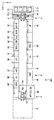
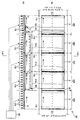
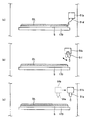
다음으로, 도 2를 참조하면서, 본 실시 형태에 의한 현상 유닛(30)에 대해 설명한다. 도 2의 (a)는, 현상 유닛(30)의 개략 상면도이며, 도 2의 (b)는, 현상 유닛(30)의 개략 측면도다. 이들 도면에 있어서는, 기판(S)과 현상 유닛(30)의 각 영역과의 위치 관계를 나타내기 위해, 각 부에 기판(S)이 배치된 상태를 도시하고 있다.Next, the developing
도시한 바와 같이, 현상 유닛(30)은, 기판(S)을 반송하기 위해, 서로 평행하게 소정의 간격으로 배열되는 복수의 롤러(170)를 구비한다. 또한, 현상 유닛(30)에는, 롤러(170)에 의한 기판(S)의 반송 방향(도 1에 도시하는 반송 라인 B의 방향과 동일함)을 따라, 도입 영역(30A), 현상액 공급 영역(30B), 제1 반송 영역(30C), 제2 반송 영역(30D) 및 린스 영역(30E)이 배치되어 있다.As shown in the drawing, the developing
복수의 롤러(170)는, 기판(S)의 폭보다도 길고, 같은 높이에 배치되어 있다. 이로 인해, 기판(S)은 롤러(170) 상에 안정적으로 지지된다. 또한, 롤러(170)의 각각은, 중심축을 회전 중심으로 하여 회전 가능하고, 구동 장치(60)에 의해 구동되어 같은 방향으로 회전할 수 있다. 이에 의해 롤러(170) 상의 기판(S)은 소정의 반송 속도로 반송된다. 복수의 롤러(170), 구동 장치(60) 및 롤러(170)와 구동 장치(60)를 결합하는 동력 전달 기구 등에 의해, 롤러 반송 기구가 구성된다.The some
도입 영역(30A)은, 외부 장치 블록(90)에 접속하고, 노광 장치(9)에 있어서 노광된 포토레지스트막이 표면에 형성된 기판(S)을 외부 장치 블록(90)으로부터 수취하고, 현상액 공급 영역(30B)에 반송한다. 단, 도입 영역(30A)과 외부 장치 블록(90) 사이에는, 반입 영역이 배치되어도 된다. 반입 영역은, 도입 영역(30A)과 마찬가지의 구성을 가질 수 있고, 외부 장치 블록(90)과 현상 유닛(30) 사이에서의 기판(S)의 반송 간격을 조정하는 버퍼로서 기능할 수 있다.The
현상액 공급 영역(30B)은 도입 영역(30A)과 연속하도록 배치되어 있다. 구체적으로는, 도입 영역(30A)과 현상액 공급 영역(30B)의 경계에 있어서의 롤러(170)의 간격은, 도입 영역(30A) 내 및 현상액 공급 영역(30B) 내에 있어서의 롤러(170)의 간격과 대략 같고, 또한, 롤러(170)의 배치 높이는, 도입 영역(30A)과 현상액 공급 영역(30B) 사이에서 같다. 이에 의해, 기판(S)은, 도입 영역(30A)으로부터 현상액 공급 영역(30B)에 원활하게 반입된다. 또한, 현상액 공급 영역(30B)에는, 기판(S)의 표면에 현상액을 공급하는 현상액 공급 노즐(50)이 설치되어 있다. 현상액 공급 노즐(50)은, 기판(S)의 반송 방향과 직교하는 방향[롤러(170)의 길이 방향과 평행한 방향]으로 연장되고, 도 2의 (a)에 도시한 바와 같이, 기판(S)의 폭보다도 약간 길다. 현상액 공급 노즐(50)은, 소정의 간격을 두고 하방으로 개방되는 복수의 구멍[또는 현상액 공급 노즐(50)의 길이 방향으로 연장되는 슬릿]을 갖고 있고, 기판(S)의 표면의 전체 폭에 대하여 현상액 공급원(도시하지 않음)으로부터의 현상액을 공급한다. 또한, 현상액 공급 노즐(50)은, 도 2의 (b)에 도시한 바와 같이, 도입 영역(30A)과 현상액 공급 영역(30B)의 경계 가까이에 배치되어 있다. 이로 인해, 도입 영역(30)으로부터 현상액 공급 영역(30B)에 반입되는 것과 대략 동시에 기판(S)에 대한 현상액의 공급이 개시된다.The
제1 반송 영역(30C)은 현상액 공급 영역(30B)과 연속하도록 배치되어 있다. 기판(S)은, 현상액 공급 영역(30B)에 있어서 공급된 현상액으로 표면이 덮인 상태로, 현상액 공급 영역(30B)으로부터 제1 반송 영역(30C)에 반입되어, 동일한 상태로 제1 반송 영역(30C) 내를 반송된다.The 1st conveyance area |
제2 반송 영역(30D)은 제1 반송 영역(30C)과 연속하도록 배치되어 있다. 제2 반송 영역(30D)에 있어서는, 기판(S)의 반송 방향을 따른 하류측에서 롤러(170)의 배치 높이에 차가 형성되어 있다. 구체적으로는, 제2 반송 영역(30D)에 위치하는 8개의 롤러(170) 중, 기판(S)의 반송 방향 상류측으로부터의 7개째의 롤러(170)가 6개째의 롤러(170)보다도 예를 들어 3mm로부터 5mm 높은 위치에 배치되고, 또한, 8개째의 롤러(170)는 6개째의 롤러(170)보다도 예를 들어 6mm로부터 10mm 높은 위치에 배치되어 있다. 이로 인해, 제2 반송 영역(30D) 내에서 롤러(170)에 의해 반송되는 기판(S)은, 반송 방향의 전단부로부터 후단부를 향해 낮아지도록 오목 형상으로 휘게 된다. 이와 같이 휘어짐으로써, 기판(S)의 표면을 덮는 현상액은, 기판(S)의 반송 방향과는 역의 방향으로 흘러 기판(S)의 후단부로부터 하방으로 흘러내린다. 롤러(170)의 하방에는, 도시하지 않은 트레이(또는 팬)가 설치되어 있다. 하방으로 흘러내린 현상액은 트레이에 수집되고, 트레이에 설치된 소정의 배관을 통과하여 회수된다. 이에 의해, 현상액을 재이용할 수 있어, 현상액을 절약하는 것이 가능해진다.2nd conveyance area |
상술한 바와 같이, 현상액 공급 영역(30B)에 있어서 현상액 공급 노즐(50)로부터 현상액이 기판(S) 상에 공급되고, 기판(S)은, 표면이 현상액으로 덮인 채 현상액 공급 영역(30B), 제1 반송 영역(30C) 및 제2 반송 영역(30D)을 롤러(170)에 의해 반송되고, 그 동안에 기판(S) 상의 포토레지스트막이 현상된다. 현상 시간은, 사용하는 포토레지스트에 따라 상이하지만, 현상액 공급 영역(30B), 제1 반송 영역(30C) 및 제2 반송 영역(30D)의 길이와, 이들 영역(30B 내지 30D)을 통과하는 기판(S)의 반송 속도에 의해 조정할 수 있다.As described above, the developing solution is supplied onto the substrate S from the developing
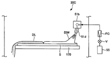
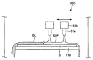
또한, 현상액 공급 영역(30B), 제1 반송 영역(30C) 및 제2 반송 영역(30D)에는, 도 2에 도시한 바와 같이, 대응하는 세정 노즐(51a, 51b, 51c)이 설치되어 있다. 본 실시 형태에서는, 세정 노즐(51a, 51b, 51c)은, 기판(S)의 반송 방향을 따라 연장되어 있다. 또한, 세정 노즐(51a, 51b, 51c)에는, 소정의 배관에 의해 탈이온수(DIW)의 공급원이 접속되어 있다. 구체적으로는, 도 3에만 개략적으로 도시한 바와 같이, 공급원(55)과 세정 노즐(51a 내지 51c)을 접속하는 배관에는, 밸브 V나 유량 조정기 FC 등이 설치되어 있다. 이 밸브 V는, 전기적으로 개폐 제어가 가능하여, 이에 의해 세정 노즐(51a 내지 51c)로부터의 DIW의 토출이 제어된다. 또한, 세정 노즐(51a 내지 51c)의 각각은, 복수의 토출부(51d)를 갖고, 각 토출부(51d)의 선단에는 토출 구멍이 형성되고, 여기에서 기판(S)을 향하여 DIW가 토출된다. 토출 구멍은, 일정한 개구 직경을 갖는 원기둥 형상의 구멍이어도 되고, 기판(S)을 향하는 방향으로 개구 직경이 넓어지는 테이퍼 형상의 구멍이어도 되고, 슬릿이어도 된다. 또한, 토출 구멍의 개구 직경 및 테이퍼 각 및 토출부(51d)의 간격은, 토출부(51d)로부터 토출되는 DIW가[예를 들어 세정 노즐(51a)과 세정 노즐(51b) 사이에 있어서도] 간극 없이 기판(S)에 도달할 수 있도록 결정되면 바람직하다. 이와 같은 구성에 의해, 공급원으로부터 세정 노즐(51a 내지 51c)에 공급되는 DIW는, 복수의 토출부(51d)로부터 기판(S)을 향해 커튼 형상으로 토출되어, 현상액을 균일하게 씻어낼 수 있다.Moreover, as shown in FIG. 2, the cleaning
도 2의 I-I선을 따른 단면도인 도 3을 참조하면, 세정 노즐(51b)은, 롤러(170)에 의한 기판 반송의 방향과 직교하는 방향에 있어서 기판(S)의 한쪽 단부(도시의 예에서는 우측 단부)의 상방에 배치되어 있다. 토출부(51d)는, 도시한 바와 같이, 연직 방향으로부터 기판(S)의 다른 쪽 단부(도시의 예에서는 좌측 단부)측을 향해 기울어져 있어, 이에 의해, 토출부(51d)로부터 토출된 DIW는, 기판(S) 상에서 대강 한쪽 단부로부터 다른쪽 단부를 향해 흐른다. 이로 인해, 기판(S) 상의 현상액(DL)은 DIW에 의해 씻어내어지게 된다. 세정 노즐(51a 및 51c)도 또한, 세정 노즐(51b)과 동일한 구성을 갖고 있다. 세정 노즐(51a 내지 51c)은, 포토레지스트막의 현상, 세정 및 건조와 같은 일련의 처리 수순에 있어서 상시 사용되는 것은 아니고, 구체적인 동작에 대해서는 후술한다.Referring to FIG. 3, which is a cross-sectional view along the line II of FIG. 2, the cleaning
린스 영역(30E)은 제2 반송 영역(30D)과 연속하도록 배치되어 있다. 구체적으로는, 린스 영역(30E)에 있어서의 기판 반송 방향을 따른 최상류측의 롤러(170)는, 제2 반송 영역(30D)에 있어서의 기판 반송 방향을 따른 최하류측의 롤러(170)에 대하여 극단적인 단차가 생기지 않도록 배치되고, 최상류측의 롤러(170)에 후속하는 롤러(170)는, 순차 높이가 낮아지도록 배치되어 있다. 이에 의해, 제2 반송 영역(30D)에 있어서(대강 오목 형상으로) 휜 기판(S)은, 린스 영역(30E)에 있어서는 역방향으로 휘고, 점차 평탄해진다. 롤러(170)의 길이 방향이나 간격 등은, 린스 영역(30E)에 있어서도 제2 반송 영역(30D) 등과 동일하다.The rinse
또한, 린스 영역(30E)에는, 예비 린스 노즐(52)이 설치되어 있다. 예비 린스 노즐(52)은, 도 2의 (a)에 도시한 바와 같이, 기판(S)의 반송 방향과 직교하는 방향으로 연장되고, 기판(S)의 폭보다도 길고, 또한, 하부에, 소정의 간격으로 복수의 구멍이 형성되어 있다. 예비 린스 노즐(52)은, 도시하지 않은 린스액(예를 들어 DIW)의 공급원과 접속되어 있고, 기판(S)의 전체 폭에 걸쳐 린스액을 토출한다. 린스액에 의해 현상액(DL)이 씻어내어져, 포토레지스트막의 현상이 실질적으로 정지된다. 바꾸어 말하면, 본 실시 형태에 있어서는, 현상액 공급 노즐(50)로부터 기판(S)의 표면에 현상액이 공급되어, 포토레지스트막의 현상이 시작되고, 예비 린스 노즐(52)로부터 기판(S)의 표면에 린스액이 공급되어, 포토레지스트막의 현상이 정지한다. 즉, 본 실시 형태에 있어서는, 현상액 공급 노즐(50)로부터 예비 린스 노즐(52)까지의 범위가 현상 영역에 상당한다.In addition, a preliminary rinse
기판 반송 방향에 대하여 예비 린스 노즐(52)의 하류측에는, 린스 노즐(53)이 설치되어 있다. 린스 노즐(53)은, 예비 린스 노즐(52)과 마찬가지로 기판(S)의 전체 폭에 걸쳐 린스액을 토출할 수 있고, 이에 의해, 린스액 중에 녹기 시작한 현상액을 린스액과 함께 씻어낼 수 있다. 또한, 린스 노즐(53)은 기울어져 배치되어, 롤러(170)에 의해 형성되는 기판(S)의 기울기를 따른 방향을 향해 린스액을 공급할 수 있다. 따라서 현상액을 효율적으로 씻어낼 수 있다.The rinse
린스액에 의해 현상액이 씻어내어진 기판(S)은, 린스 영역(30E)과 연속하도록 배치되는 건조 영역(도시하지 않음)에 반송된다. 건조 영역은, 도입 영역(30A) 등과 마찬가지의 롤러 반송 기구와, 롤러 반송 기구에 의해 반송되는 기판(S)에 대하여 청정 공기를 토출하여 기판(S)을 건조하는 에어 나이프(도시하지 않음)를 구비할 수 있다. 건조 영역에 의해 건조된 기판(S)은, 롤러 반송 기구에 의해 가열 처리 유닛(31)(도 1 참조)에 반송된다.The board | substrate S from which the developing solution was wash | cleaned with the rinse liquid is conveyed to the dry area | region (not shown) arrange | positioned so that it may be continuous with the rinse area |
또한, 린스 영역(30E)과 건조 영역 사이에, 하나 또는 복수의 린스 노즐을 갖는 다른 린스 영역을 설치해도 된다. 이에 의하면, 현상액을 보다 확실하게 씻어낼 수 있다.In addition, another rinse region having one or a plurality of rinse nozzles may be provided between the rinse
다음으로, 도 4 및 도 5를 참조하면서, 본 실시 형태에 의한 현상 유닛(30)의 동작(현상 방법)에 대해 설명한다.Next, the operation (development method) of the developing
도 4의 (a)를 참조하면, 롤러(170)에 의해 도입 영역(30A)으로부터 현상액 공급 영역(30B)에 기판(S1)이 반송되고 있다. 기판(S1)이 현상액 공급 노즐(50)의 하방을 통과하면, 현상 공급 노즐(50)로부터 기판(S1)의 표면에 현상액이 공급되어, 현상액(DL)이 기판(S1)의 표면에 머문다.Referring to FIG. 4A, the substrate S1 is conveyed from the
기판(S1)이 현상액 공급 노즐(50)의 하방을 빠져나가면, 기판(S1)의 표면 전체면이 현상액(DL)에 의해 덮이고, 이대로 기판(S1)은 현상액 공급 영역(30B)으로부터 제1 반송 영역(30C)에 반송된다[도 4의 (b) 참조]. 이때, 기판(S1)의 다음 기판(S2)이, 기판(S1)에 대하여 소정의 간격을 두고 도입 영역(30A)에 반입된다.When the board | substrate S1 exits below the developing
그 후, 기판(S1)은, 제1 반송 영역(30C)으로부터 제2 반송 영역(30D)을 통과하여 린스 영역(30E)에 도달하면, 예비 린스 노즐(52)로부터 기판(S1)에 대하여 린스액이 공급되어, 현상액(DL)이 씻어내어진다[도 5의 (a) 참조]. 도시한 기판(S1)은, 예비 린스 노즐(52)의 하방을 통과하는 도중에 있기 때문에, 예비 린스 노즐(52)을 통과한 부분에 있어서 현상액(DL)이 씻어내어지고, 통과하지 않은 부분에는 현상액(DL)이 남아있다. 또한, 후속의 기판(S2)에 있어서는, 기판(S1)에 대하여 설명한 것과 마찬가지로, 현상액 공급 노즐(50)로부터 현상액(DL)이 공급되어 표면이 현상액(DL)에 의해 덮이고, 현상액 공급 영역(30B)으로부터 제1 반송 영역(30C)에 반송되고 있다. 또한, 기판(S2)의 다음 기판(S3)이 기판 도입 영역(30A)에 반입되고 있다.After that, when the substrate S1 reaches the rinse
도 5의 (a)에 도시하는 상태로, 현상 유닛(30)이 내장되는 도포 현상 처리 시스템(100)의 가열 처리 유닛(28)에 있어서 가열 플레이트의 온도 이상이 검출되어, 도포 현상 처리 시스템(100)이 정지하고, 이에 수반하여 현상 유닛(30)의 롤러(170)가 정지했다고 하자. 이 경우, 가열 플레이트에서의 온도 이상을 나타내는 경보 신호와 롤러(170)를 정지시키는 신호에 기초하여, 세정 노즐(51a 내지 51c)과 DIW의 공급원을 연결하는 배관에 설치되는 밸브[세정 노즐(51b)에 대하여 설치되는 밸브 V(도 3)에 상당]가 개방되어, 세정 노즐(51a 내지 51c)로부터 기판(S)에 대하여 도 3에 도시한 바와 같이 DIW가 토출된다. 이에 의해, 도 5의 (b)에 화살표로 도시한 바와 같이, 기판(S1)의 표면에 남은 현상액(DL)과, 기판(S2)의 표면을 덮는 현상액(DL)이 DIW에 의해 씻어내어져, 이들 기판 상의 포토레지스트막의 현상이 정지된다.In the state shown to Fig.5 (a), in the
또한, 예를 들어 가열 처리 유닛(28)에 있어서의 온도 이상이 검출된 때에, 도포 현상 처리 시스템(100)의 조작 패널 상에 온도 이상을 알리는 경보를 표시시켜도 된다. 경보 표시로부터 온도 이상을 알게 된 조작자가, 예를 들어 조작 패널을 조작함으로써, 세정 노즐(51a 내지 51c)로부터 DIW를 토출시켜도 된다.In addition, for example, when the temperature abnormality in the
미리 정한 세정 조건[토출 유량, 토출 총량, 도 6을 참조하면서 후술하는 바와 같이 세정 노즐(51a 내지 51c)가 이동 가능한 경우에는 왕복 횟수 등]에 따른 현상액(DL)의 세정이 완료되면, 세정 노즐(51a 내지 51c)로부터의 DIW의 토출이 정지된다. 가열 플레이트에서의 온도 이상이 수복된 후에 도포 현상 처리 시스템(100)의 동작을 재개하면, 현상액이 공급되지 않은 기판(S3)(및 후속의 기판)에 대해서는, 재개 후, 현상액 공급 노즐(50)로부터 현상액이 공급되어, 소정의 기간 포토레지스트막이 현상되고, 예비 린스 노즐(52)로부터 린스액이 공급되어 현상이 정지되고, 린스액이 건조되어 가열 처리 유닛(31)에 반송된다. 이 후, 이미 설명한 후속의 각 유닛에서 처리되어 도포 현상 처리 시스템(100)의 카세트 스테이션(1)의 카세트(C)에 복귀된다. 한편, 기판(S1, S2)에 대해서는, 재개 후, 현상이 완료되지 않은 상태로 카세트 스테이션(1)의 카세트(C)에 복귀되기 때문에, 재처리가 행해진다. 즉, 기판(S1, S2)의 표면 상의 포토레지스트막이 제거되고, 세정된 후에, 도포 현상 처리 시스템(100)에 의해 처리된다.When the cleaning of the developer DL according to the predetermined cleaning conditions (discharge flow rate, total discharge amount, the number of round trips when the
또한, 세정 노즐(51a 내지 51c)로부터의 DIW의 토출은, 도포 현상 처리 시스템(100)의 조작자에 의해 정지되어도 되고, 조작자가, 기판(S1) 및 기판(S2)을 현상 유닛(30)으로부터 취출해도 된다.The discharge of the DIW from the
이상 설명한 바와 같이, 본 실시 형태의 현상 유닛(30) 및 이를 구비하는 도포 현상 처리 시스템(100)에 의하면, 현상 유닛(30) 또는 도포 현상 처리 시스템(100)에 있어서 이상이 발생하여, 표면이 현상액으로 덮인 기판이 현상 유닛(30) 내에 남은 경우이어도, 세정 노즐(51a 내지 51c)에 의해 현상액을 씻어낼 수 있기 때문에, 기판 상의 포토레지스트막의 기초층이 현상액으로 손상되거나 침식되거나 하는 것을 억제할 수 있다. 기초층이 손상되지 않으면, 재처리를 행할 수 있기 때문에, 기판을 폐기할 필요가 없어, 수율의 저하를 피하는 것이 가능해진다.As described above, according to the developing
다음으로, 본 발명의 실시 형태에 의한 현상 유닛(30)의 변형예에 대해 설명한다. 도 6을 참조하면, 세정 노즐(51b)은, 연직 방향으로 연장되는 토출부(51e)를 갖고 있고, 기판(S)의 반송 방향에 직교하는 방향[롤러(170)의 길이 방향]으로 이동 가능하다. 토출부(51e)에도 토출 구멍이 형성되어 있고, 여기서부터 DIW가 토출된다. 세정 노즐(51b)이 DIW를 토출하면서 이동함으로써, 기판(S) 상의 현상액(DL)이 씻어내어진다. 이 경우, DIW를 토출하면서 도면 중에서 좌우로 이동해도 되고, 또한, 우측 단부로부터 좌측 단부로 이동하면서 DIW를 토출하고, 좌측 단부에 도달했을 때에 DIW의 토출을 정지하여 우측 단부까지 복귀하고, 이하, 이를 몇회 반복해도 된다. 또한, 이와는 반대로, 좌측 단부로부터 우측 단부로 이동하면서 DIW를 토출하고, 우측 단부에 도달했을 때에 DIW의 토출을 정지하여 좌측 단부까지 복귀한다고 하는 수순을 반복해도 된다. 즉, 세정 노즐(51b)이 일방향으로 이동할 때에만 DIW를 토출함으로써, 세정 효율을 높일 수 있다. 또한, 세정 노즐(51a 및 51c)에 대해서도 마찬가지의 구성을 가질 수 있다. 이와 같이 하여도, 현상 유닛(30) 또는 도포 현상 처리 시스템(100)에 있어서 이상이 발생하여, 표면이 현상액으로 덮인 기판이 현상 유닛(30) 내에 남은 때이어도, 세정 노즐(51a 내지 51c)에 의해 기판 상의 현상액을 씻어낼 수 있다.Next, the modification of the developing
또한, 현상 유닛(30) 및 도포 현상 처리 시스템(100)이 정상적으로 동작하고 있는 동안에, 세정 노즐(51a 내지 51c)의 토출부(51d)[또는 (51e)]로부터 DIW가 기판(S) 상에 떨어지면, 현상 불균일이 발생하기 때문에, 예를 들어 도 7의 (a)에 도시한 바와 같이 토출부(51)의 선단이 기판(S)의 외측 상방에 위치하도록 세정 노즐(51a 내지 51c)을 배치하면 바람직하다. 또한, 도 7의 (b)에 도시하는 토출부(51f)는, 세정 노즐(51b)에 대하여 선회 가능하게 구성되어 있다. 이에 의하면, 정상 동작 시에는, 토출부(51f)의 선단이 기판(S)의 외측 상방에 위치하고, 이상에 의해 현상 유닛(30) 및 도포 현상 처리 시스템(100)이 정지한 때에, 토출부(51f)의 선단이 기판(S)의 내측 상방에 위치할 수 있다. 또한, 도 7의 (c)에 도시한 바와 같이, 도 6에 도시한 변형예의 세정 노즐(51b)을, 토출부(51e)의 선단이 기판(S)의 외측 상방에 위치할 수 있도록 이동시켜도 된다.In addition, while the developing
또한, 세정 노즐(51a 내지 51c)을 롤러(170)의 세정에 이용하는 것도 가능하다. 도 8의 (a)는, 현상 유닛(30)의 일부 상면도이며, 도 8의 (b)는, 현상 유닛(30)의 일부 측면도이다. 도시한 바와 같이, 롤러(170)의 각각에 대하여 트레이(또는 받침 접시)(51p)가 설치되어 있다. 도시의 예에서는, 트레이(51p)는, 그 상단부가 롤러(170)의 상단부보다도 낮게 위치하도록 배치되어 있고, 이에 의해, 롤러(170)의 하부만이 트레이(51p) 내에 들어갈 수 있다. 제조 로트의 사이의 도포 현상 처리 시스템(100)이 아이들 상태에 있을 때에, 세정 노즐(51a 내지 51c)로부터 DIW를 토출하면, DIW가 트레이(51p)에 저류된다. 이때, 예를 들어 롤러(170)를 구동 장치(60)(도 2)에 의해 회전시키면, 롤러(170)의 외주면 전체가 DIW에 의해 세정될 수 있다. 롤러(170)에는 기판의 이면이 접하기 때문에, 약간이기는 하지만 오염되는 경우가 있다. 이러한 오염은, 통상, 조작자가 와이프 등으로 닦아냄으로써, 세정되지만, 도 8에 도시하는 구성에 의하면, 그러한 닦아내기 세정의 빈도를 저감하는 것이 가능해진다. 세정 노즐(51a 내지 51c)을 이와 같이 이용하면, 제조 수율의 저하의 억제뿐만 아니라, 세정 빈도 또는 세정 시간의 단축을 통해 처리량의 향상에도 기여할 수 있다.It is also possible to use the
또한, 트레이(51p)를 상하 이동 가능하게 구성하고, 롤러(170)를 세정할 때에 상승시켜, 롤러(170)가 DIW 내에 잠기도록 해도 된다.In addition, the
이상, 본 발명의 실시 형태 및 변형예를 참조하면서 본 발명을 설명했지만, 본 발명은 상술한 실시 형태 및 변형예에 한정되지 않고, 첨부의 특허청구의 범위에 비추어, 다양하게 변경 또는 변형이 가능하다.As mentioned above, although this invention was demonstrated referring an embodiment and the modification of this invention, this invention is not limited to embodiment and the modification which were mentioned above, In light of the attached claim, various changes and a deformation | transformation are possible. Do.
예를 들어, 상기한 실시 형태에 있어서는, 현상액 공급 영역(30B), 제1 반송 영역(30C) 및 제2 반송 영역(30D)에 대응하는 세정 노즐(51a, 51b 및 51c)을 배치했지만, 이들 세정 노즐(51a 내지 51c) 대신에, 현상액 공급 영역(30B)으로부터 제2 반송 영역(30D)에 걸쳐 기판(S)의 반송 방향으로 연장되는 1개의 세정 노즐을 설치해도 된다.For example, in the above-mentioned embodiment, although the
또한, 세정 노즐(51a 내지 51c)을 설치하는 일 없이, 예비 린스 노즐(52)에 의해 기판(S) 상의 현상액을 씻어내도 된다. 구체적으로는, 예비 린스 노즐(52)은, 현상 유닛(30) 및 도포 현상 처리 시스템(100)이 정상적으로 동작하고 있을 때는, 도 1에 도시한 바와 같이 린스 영역(30) 내에 위치하고, 롤러(170)가 정지한 때에, 린스액(또는 DIW)을 토출하면서 린스 영역(30E)으로부터 현상액 공급 영역(30B)까지 이동할 수 있도록 구성할 수 있다.In addition, the developer on the substrate S may be washed out by the preliminary rinse
또한, 세정 노즐(51a 내지 51c) 대신에, 기판(S)의 반송 방향과 직교 또는 교차하는 방향으로 연장되어, DIW를 토출 가능하고, 현상액 공급 영역(30B)으로부터 제2 반송 영역(30D)에 걸쳐 기판(S)의 반송 방향과 평행한 방향으로 이동 가능한 세정 노즐을 설치해도 된다.In addition, instead of the
또한, 세정 노즐(51a 내지 51c)(또는, 이들을 대신하는 1개의 세정 노즐)에는, 토출 구멍을 갖는 토출부(51d)가 설치되어 있었지만, 다른 실시 형태에서는, 토출부(51d) 및 토출 구멍 대신에, 세정 노즐(51a 내지 51c)(1개의 세정 노즐)의 하면에 슬릿을 설치하여, 슬릿으로부터 DIW를 토출시켜도 된다.Moreover, although the
또한, 기판(S)의 반송 방향에 직교하는 방향[롤러(170)의 길이 방향]으로 이동 가능한 세정 노즐(51b)(도 6)은, 연직 방향으로부터 기울어진 토출부(51d)를 가져도 된다.In addition, the cleaning
또한, 롤러(170)가 정지한 때에, 기판(S)을 경사지게 해도 된다. 구체적으로는, 세정 노즐(51a 내지 51c)(또는 1개의 세정 노즐)이 상방에 설치되는 측[도 3에서 말하면, 기판(S)의 우측 단부]의 하방에, 롤러(170)의 사이를 통과하여 상하 이동할 수 있도록 승강 핀을 배치하고, 승강 기구에 의해 승강 핀을 상승시켜 기판(S)을 기울여도 된다. 이에 의하면, 세정 노즐(51a 내지 51c)(또는 1개의 세정 노즐)로부터의 DIW에 의해 현상액을 씻어내는 경우에 비해, 기판(S) 상의 현상액을 보다 신속하게 씻어내는 것이 가능해진다.In addition, you may incline the board | substrate S when the
또한, 세정 노즐(51a 내지 51c)이 동작하여 기판 상의 현상액을 씻어내는 예로서, 도포 현상 처리 시스템(100)의 가열 처리 유닛(28)에 있어서의 온도 이상에 의해 롤러(170)가 정지한 경우를 예시했지만, 이에 한정되지 않는다. 예를 들어, 도포 현상 처리 시스템(100)의 냉각 유닛(25, 32)에 있어서의 온도 이상, 포토레지스트 도포 유닛(26)에 있어서의 포토레지스트액 탱크 내의 포토레지스트액의 잔량 저하, 또는 현상 유닛(30)에 있어서의 현상액이나 린스액의 누출 등에 대응한 경보 신호를 이용하여, 롤러(170)를 정지하고, 세정 노즐(51a 내지 51c)을 동작시키도록 해도 된다. 또한, 현상 유닛(30)을 구비하는 도포 현상 처리 시스템(100)이 설치되는 클린룸에서 정전이 있는 때에도, 예를 들어 백업 전원에 의해, 세정 노즐(51a 내지 51c)을 동작시키도록 해도 된다. 또한, 도 3에 도시하는 밸브 V로서 노멀리 오픈형의 밸브를 사용하면 바람직하다.In addition, when the
또한, 제2 반송 영역(30D)에 있어서의 기판(S)의 반송 방향을 따른 하류측에, 기판(S)의 표면에 대하여 청정 공기를 분사하는 블로우 노즐을 설치해도 된다. 이에 의하면, 린스 영역(30E)에 있어서 린스액에 의해 현상액을 씻어내는 것에 앞서, 기판(S) 상의 현상액을 제거함으로써, 린스 효과를 보다 높일 수 있다. 이 경우, 포토레지스트막의 현상은, 블로우 노즐에 의해 현상액이 제거됨으로써 실질적으로 정지된다. 또한, 블로우 노즐로부터의 청정 공기에 의해 기판(S)의 표면이 완전하게 건조하는 것을 피하기 위해, 블로우 노즐과 예비 린스 노즐(52)은 서로 근접하여(예를 들어 30mm의 간격으로) 배치되면 바람직하다.Moreover, you may provide the blow nozzle which injects clean air to the surface of the board | substrate S in the downstream side along the conveyance direction of the board | substrate S in 2nd conveyance area |
또한, 세정 노즐(51a 내지 51c)(또는 1개의 세정 노즐)을 2 종류의 액체를 공급할 수 있도록 구성해도 된다. 이에 의하면, 사용하는 레지스트에 따라서는, 예를 들어 처음에 DIW를 토출하여 현상액을 씻어내고, 이소프로필알코올 등의 유기 용제로 다시 세정하는 것도 가능해진다.The
또한, 예비 린스 노즐(52)은, 전술한 바와 같이, 하부에, 소정의 간격으로 복수의 미세 구멍이 형성되어 있다. 이것은, 린스액을 토출할 때에, 기판(S)에 부여하는 충격을 작게 하기 위해서이다. 충격이 작으므로, 린스액에 의한 현상의 얼룩을 방지할 수 있다.As described above, the preliminary rinse
또한, 예비 린스 노즐(52)의 다른 형태로서, 복수의 미세 구멍을 형성하는 대신, 예비 린스 노즐(52)의 하부에, 소정의 폭의 슬릿을 형성해도 된다. 이와 같은 형상으로도, 기판(S)에 부여하는 충격을 작게 할 수 있다. 예비 린스 노즐(52)은, 기판(S)에 부여하는 충격이 작아지도록 고려되어 있다.As another form of the preliminary rinse
린스 노즐(53)은, 예비 린스 노즐(52)과는 형상이나 목적이 상이하다. 린스 노즐(53)은, 하부에 소정의 간격으로 린스액을 토출하는 복수의 토출구가 형성되어 있다. 그리고 이 각각의 토출구로부터, 스프레이 형상(원추 형상 또는 커튼 형상)으로 린스액이 토출된다. 스프레이 형상으로 린스액을 토출하므로, 기판(S)에 어느 정도의 충격을 부여하는 것이 가능하여, 현상 처리 시에 녹기 시작한 불필요한 포토레지스트(스컴 또는 쓰레기 등)를 깔끔하게 제거하는 것이 가능하다. 린스 노즐(53)로부터 토출된 린스액이 기판(S)에 도달하는 영역은, 이미 현상이 정지되어 있으므로, 기판(S)에 어느 정도의 충격을 부여해도 현상의 얼룩이 발생하지 않는다. 또한, 예비 린스 노즐(52)과 비교하여, 린스 노즐(53)은, 단시간에 광범위를, 게다가 적은 린스액량으로 세정하는 것이 가능하다.The rinse
그리고 세정 노즐(51a, 51b, 51c)도, 린스 노즐(53)과 마찬가지로, 토출부(51d)로부터 스프레이 형상(원추 형상 또는 커튼 형상)으로 세정액을 토출한다. 따라서, 단시간에 광범위를, 게다가 적은 세정액량으로 세정하는 것이 가능하다. 세정 노즐(51a, 51b, 51c)로부터 세정액이 공급될 때는, 통상 상태가 아닌, 비상 시이며, 기판(S)은 그 후 회수되어 재처리되므로, 기판(S)에 어느 정도의 충격을 부여해도 문제없다.Similarly to the rinse
상술한 바와 같이, 세정 노즐(51a, 51b, 51c), 예비 린스 노즐(52), 린스 노즐(53)은, 각각의 용도에 따른 형상으로 되어 있다.As described above, the
또한, 상술한 실시 형태에서는, 세정 노즐(51a, 51b, 51c)로부터 세정액 또는 탈이온수(DIW)를 기판(S)에 공급했지만, 순수 또는, 그 밖의 현상을 정지할 수 있는 액을 공급해도 된다.In addition, although the cleaning liquid or deionized water DIW was supplied to the board | substrate S from the
또한, 상술한 실시 형태에서, 세정 노즐(51a, 51b, 51c)을, 롤러(170)의 세정에 이용했다. 또한, 제2 반송 영역(30D)의 롤러(170)가 가장 현상 처리에서 오염되기 쉽다. 따라서, 제2 반송 영역(30D)의 롤러(170)의 세정 시간을, 다른 영역의 롤러(170)의 세정 시간보다도 길게 해도 된다. 제2 반송 영역(30D)의 롤러(170)가 가장 오염되기 쉬운 이유를 설명한다. 현상이 진행됨에 따라, 현상액에 녹기 시작한 불필요한 물질의 양이 증가한다. 그리고 그 현상액이 기판(S)으로부터 흘러내려, 롤러(170)에 부착되기 때문이다. 또한, 롤러(170)의 세정 시간을, 현상액 공급 영역(30B)을 가장 짧게 하고, 제2 반송 영역(30D)에 가까이 감에 따라 길게 해도 된다.In addition, in embodiment mentioned above, the cleaning
본 발명에서는, 도포 현상 처리 시스템(100)이 통상의 가동 상태에서 현상 처리를 정지하기 위한 예비 린스 노즐(52), 린스 노즐(53)에 더하여, 세정 노즐(51a, 51b, 51c)을 설치했다. 이와 같은 구성에 의해, 도포 현상 처리 시스템(100)에 이상 상태가 발생하여, 아직 현상 처리 중의 기판이, 현상액 공급 영역(30)이나 제1 반송 영역(30)이나 제2 반송 영역(30)에서 비상 정지해도, 이들 영역에 남겨진 기판(S)의 현상을 확실하게 정지하는 것이 가능해진다.In the present invention, in addition to the preliminary rinse
상술한 실시 형태에 있어서는, 주로 FPD용 글래스 기판을 이용하는 경우를 설명했지만, 글래스 기판에 한하지 않고 수지 기판이나 반도체 기판을 이용하는 경우에도 본 발명은 적용 가능하다.In the above-mentioned embodiment, the case where the glass substrate for FPD is mainly used was demonstrated, but this invention is applicable also when using not only a glass substrate but a resin substrate and a semiconductor substrate.
100 : 도포 현상 처리 시스템
1 : 카세트 스테이션
2 : 처리 스테이션
4 : 인터페이스 스테이션
9 : 노광 장치
30 : 현상 유닛
30A : 도입 영역
30B : 현상액 공급 영역
30C : 제1 반송 영역
30D : 제2 반송 영역
30E : 린스 영역
50 : 현상액 공급 노즐
51a 내지 51c : 세정 노즐
51d, 51e, 51f : 토출부
52 : 예비 린스 노즐
53 : 린스 노즐
60 : 구동 기구
170 : 롤러
S : 기판
DL : 현상액
DIW : 탈이온수100: coating and developing treatment system
1: cassette station
2: processing station
4: interface station
9: exposure apparatus
30: developing unit
30A: Introduction Area
30B: Developer Supply Area
30C: first conveying area
30D: second conveying area
30E: Rinse Zone
50: developer supply nozzle
51a to 51c: cleaning nozzle
51d, 51e, 51f: discharge part
52: preliminary rinse nozzle
53: Rinse Nozzle
60: drive mechanism
170: roller
S: Substrate
DL: Developer
DIW: Deionized Water
Claims (11)
상기 반송 기구에 의해 반송되는 상기 기판에 현상액을 공급하는 현상액 공급부와,
상기 현상액 공급부에 대하여, 상기 반송 기구에 의해 반송되는 상기 기판의 반송 방향의 하류측에 설치되고, 상기 현상액이 공급되어 표면이 상기 현상액으로 덮인 상기 기판이 상기 반송 기구에 의해 반송되는 현상 영역과,
상기 현상 영역에 있어서, 상기 반송 기구가 정지한 때에 상기 현상 영역에 있는 상기 기판에 대하여 세정액을 공급하는 세정액 공급부
를 구비하는, 현상 장치A conveyance mechanism for conveying the substrate,
A developing solution supply section for supplying a developing solution to the substrate conveyed by the carrying mechanism;
A developing region provided on the downstream side of the conveying direction of the substrate conveyed by the conveying mechanism with respect to the developing solution supply section, wherein the developing liquid is supplied and the substrate covered with the developer is conveyed by the conveying mechanism;
In the developing region, a cleaning liquid supply unit for supplying a cleaning liquid to the substrate in the developing region when the transport mechanism is stopped.
Developing apparatus provided with
상기 세정액 공급부가, 상기 세정 영역에 있어서 상기 반송 기구에 의해 상기 세정 영역에 반송되는 상기 기판에 대하여 세정액을 공급하는, 현상 장치.The cleaning region according to claim 4, further comprising a cleaning region provided on a downstream side of the conveying direction with respect to the developing region, wherein a developing solution covering the surface of the substrate conveyed by the conveying mechanism is washed with a cleaning liquid,
The developing apparatus according to claim 1, wherein the cleaning liquid supply unit supplies the cleaning liquid to the substrate conveyed to the cleaning region by the transfer mechanism in the cleaning region.
노광된 상기 포토레지스트막을 현상하는 제5항에 기재된 현상 장치를 구비하는, 도포 현상 처리 시스템.A photoresist film forming apparatus for forming a photoresist film on a substrate;
The coating and developing process system provided with the developing apparatus of Claim 5 which develops the exposed said photoresist film.
노광된 포토레지스트막을 갖는 기판에 대하여, 반송 기구에 의해 기판을 반송하면서 현상액을 공급하는 공정과,
상기 현상액으로 표면이 덮인 상기 기판을 상기 반송 기구에 의해 반송하는 공정과,
상기 현상 장치에 있어서 발생한 또는 외부 기기로부터 수신한 경보 신호에 응답하여 상기 반송 기구를 정지하는 공정과,
상기 반송 기구를 정지하는 공정에 의해 반송이 정지한 상기 기판이며, 표면이 상기 현상액으로 덮인 상기 기판에 대하여 세정액을 공급하는 공정
을 포함하는, 포토레지스트막의 현상 방법.It is a method of developing the said photoresist film using the developing apparatus which forms a photoresist film on a board | substrate, and develops the exposed said photoresist film,
Supplying a developing solution to a substrate having an exposed photoresist film while conveying the substrate by a transfer mechanism;
Conveying the substrate covered with the developer by the transfer mechanism;
Stopping the conveyance mechanism in response to an alarm signal generated in the developing apparatus or received from an external device;
A step of supplying a cleaning liquid to the substrate on which the conveyance is stopped by the step of stopping the conveying mechanism, the surface of which is covered with the developer;
A photoresist film development method comprising a.
기판을 반송하는 반송 기구와,
상기 반송 기구에 의해 반송되는 상기 기판에 현상액을 공급하는 현상액 공급부와,
상기 현상액 공급부에 대하여, 상기 반송 기구에 의해 반송되는 상기 기판의 반송 방향의 하류측에 설치되고, 상기 현상액이 공급되어 표면이 상기 현상액으로 덮인 상기 기판이 상기 반송 기구에 의해 반송되는 현상 영역과,
상기 현상 영역에 대하여 상기 반송 방향의 하류측에 설치되고, 상기 기판에 세정액을 공급하여, 현상을 정지시키는 세정 영역과,
상기 현상 영역에 설치되고, 현상액으로 덮인 기판의 반송이 비상 정지한 때에, 상기 현상 영역의 기판에 세정액을 공급하기 위한 노즐
을 구비하는, 현상 장치.It is a developing apparatus which performs a developing process to a board | substrate,
A conveyance mechanism for conveying the substrate,
A developing solution supply section for supplying a developing solution to the substrate conveyed by the carrying mechanism;
A developing region provided on the downstream side of the conveying direction of the substrate conveyed by the conveying mechanism with respect to the developing solution supply section, wherein the developing liquid is supplied and the substrate covered with the developer is conveyed by the conveying mechanism;
A cleaning region provided on the downstream side of the conveying direction with respect to the developing region, for supplying a cleaning liquid to the substrate to stop developing;
Nozzle for supplying the cleaning liquid to the substrate of the said developing area when the conveyance of the board | substrate provided in the said developing area and covered with the developing solution has stopped emergencyly.
And a developing apparatus.
현상 처리를 정지하기 위해, 이동 중의 기판에 세정액을 공급하는 린스 노즐과,
현상 처리 중의 기판의 이동이 비상 정지한 때에, 현상 처리 중의 상기 기판에 세정액을 공급하기 위한, 상기 린스 노즐과는 다른 세정 노즐
을 구비하는, 현상 장치.A developing device which performs a developing process while moving a substrate coated with a developing solution horizontally, comprising a developing nozzle for supplying a developing solution to a substrate;
A rinse nozzle for supplying a cleaning liquid to the substrate during movement to stop the developing process;
A cleaning nozzle different from the rinse nozzle for supplying a cleaning liquid to the substrate during the developing process when the movement of the substrate during the developing process is emergency stop.
And a developing apparatus.
기판에 현상액을 공급하는 현상 노즐과,
이 현상 노즐로부터 공급된 현상액으로 덮인 기판의 반송이, 현상 처리 중에 비상 정지한 때에, 현상 처리 중의 상기 기판에 세정액을 공급하기 위한 세정 노즐
을 구비하는, 현상 장치.
It is a developing apparatus which performs a developing process to a board | substrate, conveying a board | substrate horizontally,
A developing nozzle for supplying a developer to the substrate;
A cleaning nozzle for supplying a cleaning liquid to the substrate during the developing process when the conveyance of the substrate covered with the developing solution supplied from this developing nozzle is emergency stop during the developing process.
And a developing apparatus.
Applications Claiming Priority (2)
| Application Number | Priority Date | Filing Date | Title |
|---|---|---|---|
| JP2010273529A JP5449116B2 (en) | 2010-12-08 | 2010-12-08 | Developing device, developing coating system including the same, and developing method |
| JPJP-P-2010-273529 | 2010-12-08 |
Publications (1)
| Publication Number | Publication Date |
|---|---|
| KR20120064038A true KR20120064038A (en) | 2012-06-18 |
Family
ID=46505462
Family Applications (1)
| Application Number | Title | Priority Date | Filing Date |
|---|---|---|---|
| KR1020110130164A KR20120064038A (en) | 2010-12-08 | 2011-12-07 | Developping apparatus and developping and coating system and developping method |
Country Status (2)
| Country | Link |
|---|---|
| JP (1) | JP5449116B2 (en) |
| KR (1) | KR20120064038A (en) |
Cited By (1)
| Publication number | Priority date | Publication date | Assignee | Title |
|---|---|---|---|---|
| CN110610853A (en) * | 2018-06-15 | 2019-12-24 | 东京毅力科创株式会社 | Substrate processing apparatus and substrate processing method |
Families Citing this family (3)
| Publication number | Priority date | Publication date | Assignee | Title |
|---|---|---|---|---|
| JP6418531B2 (en) * | 2015-03-05 | 2018-11-07 | 新電元工業株式会社 | RESIST DEVELOPING DEVICE, RESIST DEVELOPING METHOD, AND SEMICONDUCTOR DEVICE MANUFACTURING METHOD |
| JP7058550B2 (en) * | 2018-05-16 | 2022-04-22 | 東京エレクトロン株式会社 | Development processing equipment and development processing method |
| CN110794656A (en) * | 2018-08-03 | 2020-02-14 | 夏普株式会社 | Method for manufacturing substrate having resist film formed thereon and process control system therefor |
Family Cites Families (1)
| Publication number | Priority date | Publication date | Assignee | Title |
|---|---|---|---|---|
| JP3704064B2 (en) * | 2001-07-05 | 2005-10-05 | 東京エレクトロン株式会社 | Liquid processing apparatus and liquid processing method |
-
2010
- 2010-12-08 JP JP2010273529A patent/JP5449116B2/en not_active Expired - Fee Related
-
2011
- 2011-12-07 KR KR1020110130164A patent/KR20120064038A/en not_active Application Discontinuation
Cited By (1)
| Publication number | Priority date | Publication date | Assignee | Title |
|---|---|---|---|---|
| CN110610853A (en) * | 2018-06-15 | 2019-12-24 | 东京毅力科创株式会社 | Substrate processing apparatus and substrate processing method |
Also Published As
| Publication number | Publication date |
|---|---|
| JP5449116B2 (en) | 2014-03-19 |
| JP2012124308A (en) | 2012-06-28 |
Similar Documents
| Publication | Publication Date | Title |
|---|---|---|
| KR100357313B1 (en) | Method of processing resist onto substrate and resist processing | |
| JP5058848B2 (en) | Transport arm cleaning apparatus, transport arm cleaning method, program, and computer storage medium | |
| JP2009297718A (en) | Coating device | |
| KR20110094269A (en) | System and method for rinse optimization | |
| KR101299763B1 (en) | Substrate cooling device and substrate cooling method | |
| KR20120064039A (en) | Developing method and developing apparatus and coating and developing apparatus with it | |
| JP2007311603A (en) | Processing liquid supply apparatus, processing liquid supply method, and control program for processing liquid supply | |
| WO2003105201A1 (en) | Substrate processing device, substrate processing method, and developing device | |
| JP2001157863A (en) | Coater | |
| KR20120064038A (en) | Developping apparatus and developping and coating system and developping method | |
| KR101299898B1 (en) | Substrate cooling device | |
| JP4318709B2 (en) | Development processing method and development processing apparatus | |
| KR100897351B1 (en) | Method and apparatus of developing substrate | |
| JP6204269B2 (en) | Liquid feeding system cleaning method, liquid feeding system, and computer-readable recording medium | |
| JP7058550B2 (en) | Development processing equipment and development processing method | |
| KR102593787B1 (en) | Substrate processing apparatus, substrate processing method and storage medium for computer | |
| JP5288383B2 (en) | Coating processing apparatus and coating processing method | |
| JP4152871B2 (en) | Nozzle and substrate processing apparatus | |
| JP5290837B2 (en) | Substrate processing apparatus and substrate processing method | |
| KR102075685B1 (en) | Apparatus and method for washing mask | |
| TWI635554B (en) | Substrate treating method | |
| JP2008166478A (en) | Resist liquid supply device and substrate processing system | |
| JP2005252045A (en) | Method and device for forming application film | |
| JP4014035B2 (en) | Liquid processing equipment | |
| JP2001252604A (en) | Treating liquid discharge nozzle and liquid treating device |
Legal Events
| Date | Code | Title | Description |
|---|---|---|---|
| WITN | Withdrawal due to no request for examination |