KR20100133446A - Immersion system, exposure apparatus, exposing method and device fabricating method - Google Patents
Immersion system, exposure apparatus, exposing method and device fabricating method Download PDFInfo
- Publication number
- KR20100133446A KR20100133446A KR1020107023702A KR20107023702A KR20100133446A KR 20100133446 A KR20100133446 A KR 20100133446A KR 1020107023702 A KR1020107023702 A KR 1020107023702A KR 20107023702 A KR20107023702 A KR 20107023702A KR 20100133446 A KR20100133446 A KR 20100133446A
- Authority
- KR
- South Korea
- Prior art keywords
- liquid
- substrate
- liquid recovery
- distance
- exposure
- Prior art date
Links
Images


Classifications
-
- G—PHYSICS
- G03—PHOTOGRAPHY; CINEMATOGRAPHY; ANALOGOUS TECHNIQUES USING WAVES OTHER THAN OPTICAL WAVES; ELECTROGRAPHY; HOLOGRAPHY
- G03F—PHOTOMECHANICAL PRODUCTION OF TEXTURED OR PATTERNED SURFACES, e.g. FOR PRINTING, FOR PROCESSING OF SEMICONDUCTOR DEVICES; MATERIALS THEREFOR; ORIGINALS THEREFOR; APPARATUS SPECIALLY ADAPTED THEREFOR
- G03F7/00—Photomechanical, e.g. photolithographic, production of textured or patterned surfaces, e.g. printing surfaces; Materials therefor, e.g. comprising photoresists; Apparatus specially adapted therefor
- G03F7/70—Microphotolithographic exposure; Apparatus therefor
- G03F7/70216—Mask projection systems
- G03F7/70341—Details of immersion lithography aspects, e.g. exposure media or control of immersion liquid supply
-
- G—PHYSICS
- G03—PHOTOGRAPHY; CINEMATOGRAPHY; ANALOGOUS TECHNIQUES USING WAVES OTHER THAN OPTICAL WAVES; ELECTROGRAPHY; HOLOGRAPHY
- G03F—PHOTOMECHANICAL PRODUCTION OF TEXTURED OR PATTERNED SURFACES, e.g. FOR PRINTING, FOR PROCESSING OF SEMICONDUCTOR DEVICES; MATERIALS THEREFOR; ORIGINALS THEREFOR; APPARATUS SPECIALLY ADAPTED THEREFOR
- G03F7/00—Photomechanical, e.g. photolithographic, production of textured or patterned surfaces, e.g. printing surfaces; Materials therefor, e.g. comprising photoresists; Apparatus specially adapted therefor
- G03F7/20—Exposure; Apparatus therefor
- G03F7/2041—Exposure; Apparatus therefor in the presence of a fluid, e.g. immersion; using fluid cooling means
-
- H—ELECTRICITY
- H01—ELECTRIC ELEMENTS
- H01L—SEMICONDUCTOR DEVICES NOT COVERED BY CLASS H10
- H01L21/00—Processes or apparatus adapted for the manufacture or treatment of semiconductor or solid state devices or of parts thereof
- H01L21/02—Manufacture or treatment of semiconductor devices or of parts thereof
- H01L21/027—Making masks on semiconductor bodies for further photolithographic processing not provided for in group H01L21/18 or H01L21/34
- H01L21/0271—Making masks on semiconductor bodies for further photolithographic processing not provided for in group H01L21/18 or H01L21/34 comprising organic layers
- H01L21/0273—Making masks on semiconductor bodies for further photolithographic processing not provided for in group H01L21/18 or H01L21/34 comprising organic layers characterised by the treatment of photoresist layers
- H01L21/0274—Photolithographic processes
- H01L21/0275—Photolithographic processes using lasers
Abstract
액침 시스템은, 광학 부재 및 액체를 통하여 노광 광으로 기판이 노광되는 액침 노광에 이용되며, 이 액침 시스템은 광학 부재와 기판 사이의 노광 광의 광로를 액체로 채운다. 액침 시스템은 노광 광의 광로 주위에 배치되고 제 1 방향으로 향하는 제 1 면을 갖는 제 1 부재; 노광 광의 광로에 대하여 제 1 면의 외측에 배치된 액체 회수구를 갖는 제 2 부재; 제 1 방향과 평행으로 제 1 부재를 이동시킬 수 있는 제 1 구동 장치; 및 제 1 부재와 독립적으로 제 1 방향과 평행으로 제 2 부재를 이동시킬 수 있는 제 2 구동 장치를 포함하며, 여기서, 제 1 면과 물체의 표면 사이의 공간에 액체를 유지할 수 있으며; 액체 회수구와 물체의 표면 사이의 액체가 액체 회수구를 통해 회수된다.The liquid immersion system is used for liquid immersion exposure in which the substrate is exposed to the exposure light through the optical member and the liquid, and the liquid immersion system fills the optical path of the exposure light between the optical member and the substrate with the liquid. The immersion system includes a first member disposed around an optical path of exposure light and having a first surface facing in a first direction; A second member having a liquid recovery port disposed outside the first surface with respect to the optical path of the exposure light; A first drive device capable of moving the first member in parallel with the first direction; And a second drive device capable of moving the second member in parallel with the first direction independently of the first member, wherein the liquid can hold liquid in the space between the first face and the surface of the object; Liquid between the liquid recovery port and the surface of the object is recovered through the liquid recovery port.

Description
본 발명은 액침 시스템, 노광 장치, 노광 방법 및 디바이스 제조 방법에 관한 것이다.The present invention relates to a liquid immersion system, an exposure apparatus, an exposure method and a device manufacturing method.
본원은 내용이 본원에 참조에 의해 포함되는 2008년 3월 27일자로 출원된 미국 가출원 제61/064,810호 및 2009년 3월 23일자로 출원된 미국 출원에 대해 우선권을 주장한다.This application claims priority to US Provisional Application No. 61 / 064,810, filed Mar. 27, 2008, the content of which is incorporated herein by reference, and US Application, filed March 23, 2009.
미국 특허출원공개 제2006/0250593호 및 미국 특허출원공개 제2007/0296939호에 개시된 바와 같이, 포토리소그래피에 이용되는 노광 장치 중에서, 액체를 통하여 노광 광으로 기판을 노광하는 액침 노광 장치가 공지되어 있다.As disclosed in US Patent Application Publication No. 2006/0250593 and US Patent Application Publication No. 2007/0296939, a liquid immersion exposure apparatus is known which exposes a substrate with exposure light through a liquid among exposure apparatuses used for photolithography. .
액침 노광 장치에서는, 투영 광학계와 같은 광학 부재와 기판 사이의 노광 광의 광로를 액체로 충분히 채우는 것이 중요하다. 광로가 액체로 충분히 채워질 수 없다면, 예를 들어, 액체 중에 기포와 같은 기체 부분이 발생한다면, 기판에 형성되는 패턴에 결함이 발생할 수도 있는 등의 노광 불량이 발생할 수도 있다. 또한, 예를 들어, 광학 부재와 기판 사이의 광로가 액체로 채워진 상태에서 기판이 고속으로 이동되는 경우, 액체로 광로를 충분히 그리고 연속적으로 채우기가 어려워지고, 액체가 소정 공간으로부터 누출되거나 기판 상에 잔류하거나 등등이 행해질 수도 있다. 또한, 누출 또는 잔류 액체의 기화열이 광로의 온도 변화, 기판과 같은 다양한 부재의 열 변형 등을 초래할 수도 있다. 이 경우에도, 노광 불량이 발생할 수도 있다. 그 결과, 불량 디바이스가 생산될 수 있다.In the liquid immersion exposure apparatus, it is important to sufficiently fill the optical path of the exposure light between the optical member such as the projection optical system and the substrate with a liquid. If the optical path cannot be sufficiently filled with liquid, for example, if gaseous portions such as bubbles occur in the liquid, poor exposure may occur, such as a defect may occur in the pattern formed on the substrate. Also, for example, when the substrate is moved at high speed while the optical path between the optical member and the substrate is filled with liquid, it becomes difficult to sufficiently and continuously fill the optical path with liquid, and liquid leaks from a predetermined space or on the substrate. Remaining or the like may be done. In addition, the heat of vaporization of the leaking or residual liquid may cause a change in temperature of the optical path, thermal deformation of various members such as a substrate, and the like. Even in this case, exposure failure may occur. As a result, a defective device can be produced.
본 발명의 일부 양태의 목적은 노광 광의 광로를 액체로 충분히 채울 수 있는 액침 시스템을 제공하는 것이다. 본 발명의 양태의 다른 목적은 노광 불량을 억제할 수 있는 노광 장치 및 노광 방법 양자를 제공하는 것이다. 본 발명의 양태의 또 다른 목적은 불량 디바이스의 생산을 억제할 수 있는 디바이스 제조 방법을 제공하는 것이다.It is an object of some aspects of the present invention to provide an immersion system capable of sufficiently filling an optical path of exposure light with liquid. Another object of an aspect of the present invention is to provide both an exposure apparatus and an exposure method capable of suppressing exposure failure. Another object of an aspect of the present invention is to provide a device manufacturing method which can suppress the production of a defective device.
본 발명의 제 1 양태는 액침 노광에 이용되는 액침 시스템을 제공하며, 이 액침 시스템은, 액체로 채워지는 광학 부재와 기판 사이의 노광 광의 광로 주위에 배치되고 제 1 방향으로 향하는 제 1 면을 갖는 제 1 부재로서, 제 1 면과 물체의 표면 사이의 공간에 액체를 유지할 수 있는, 상기 제 1 부재; 노광 광의 광로에 대하여 제 1 면의 외측에 배치된 액체 회수구를 갖는 제 2 부재로서, 액체 회수구와 물체의 표면 사이의 액체의 적어도 일부가 액체 회수구를 통해 회수되는, 상기 제 2 부재; 적어도 제 1 방향으로 제 1 부재를 이동시킬 수 있는 제 1 구동 장치; 및 제 1 부재와 독립적으로 적어도 제 1 방향으로 제 2 부재를 이동시킬 수 있는 제 2 구동 장치를 포함한다.A first aspect of the invention provides a liquid immersion system for use in liquid immersion exposure, the liquid immersion system having a first face disposed around a light path of exposure light between an optical member and a substrate filled with a liquid and directed in a first direction A first member, the first member capable of holding a liquid in a space between the first surface and the surface of the object; A second member having a liquid recovery port disposed outside the first surface with respect to an optical path of exposure light, the second member wherein at least a portion of the liquid between the liquid recovery port and the surface of the object is recovered through the liquid recovery port; A first drive device capable of moving the first member in at least a first direction; And a second drive device capable of moving the second member in at least the first direction independently of the first member.
본 발명의 제 2 양태는 액침 노광에 이용되는 액침 시스템을 제공하며, 이 액침 시스템은, 액체로 채워지는 광학 부재와 기판 사이의 노광 광의 광로 주위에 배치되고 제 1 방향으로 향하는 제 1 면을 갖는 제 1 부재로서, 제 1 면과 물체의 표면 사이의 공간에 액체를 유지할 수 있는, 상기 제 1 부재; 노광 광의 광로에 대하여 제 1 면의 외측에 배치된 액체 회수구를 갖는 제 2 부재로서, 액체 회수구와 물체의 표면 사이의 액체의 적어도 일부가 액체 회수구를 통해 회수되는, 상기 제 2 부재; 및 적어도 제 1 방향으로의 제 1 부재와 제 2 부재 사이의 상대 이동을 제어할 수 있는 구동 장치를 포함하며, 액체 회수구는 제 1 회수 영역, 및 노광 광의 광로에 대하여 제 1 면의 외측에 배치된 제 2 회수 영역을 가지며, 제 1 방향에서의 물체의 표면과 제 1 회수 영역 사이의 거리가 제 1 방향에서의 물체의 표면과 제 2 회수 영역 사이의 거리보다 크며, 제 1 방향에서의 제 1 회수 영역과 제 1 면 사이의 위치 관계가 조정될 수 있다.A second aspect of the present invention provides an immersion system for use in immersion exposure, which has a first surface disposed around an optical path of exposure light between an optical member and a substrate filled with a liquid and directed in a first direction. A first member, the first member capable of holding a liquid in a space between the first surface and the surface of the object; A second member having a liquid recovery port disposed outside the first surface with respect to an optical path of exposure light, the second member wherein at least a portion of the liquid between the liquid recovery port and the surface of the object is recovered through the liquid recovery port; And a drive device capable of controlling relative movement between the first member and the second member in at least the first direction, wherein the liquid recovery port is disposed outside of the first surface with respect to the first recovery region and the optical path of the exposure light. Having a second recovery region, the distance between the surface of the object in the first direction and the first recovery region is greater than the distance between the surface of the object in the first direction and the second recovery region, The positional relationship between the first recovery area and the first surface can be adjusted.
본 발명의 제 3 양태는 액체를 통하여 노광 광으로 기판을 노광하는 노광 장치를 제공하며, 이 노광 장치는 제 1 양태 및 제 2 양태에 따른 액침 시스템을 포함한다.A third aspect of the invention provides an exposure apparatus for exposing a substrate with exposure light through a liquid, the exposure apparatus comprising a liquid immersion system according to the first and second aspects.
본 발명의 제 4 양태는 디바이스 제조 방법을 제공하며, 이 디바이스 제조 방법은 제 3 양태에 따른 노광 장치를 이용하여 기판을 노광하는 단계; 및 노광된 기판을 현상하는 단계를 포함한다.A fourth aspect of the present invention provides a device manufacturing method, comprising: exposing a substrate using an exposure apparatus according to the third aspect; And developing the exposed substrate.
본 발명의 제 5 양태는 액체를 통하여 노광 광으로 기판을 노광하는 노광 방법을 제공하며, 이 노광 방법은 제 1 양태 및 제 2 양태에 따른 액침 시스템을 이용하여 광학 부재와 기판 사이의 노광 광의 광로를 액체로 채우는 단계; 및 광학 부재와 액체를 통하여 기판에 노광 광을 조사하는 단계를 포함한다.A fifth aspect of the invention provides an exposure method for exposing a substrate with exposure light through a liquid, the exposure method using an optical path between the optical member and the substrate using an immersion system according to the first and second aspects. Filling with a liquid; And irradiating the exposure light to the substrate through the optical member and the liquid.
본 발명의 제 6 양태는 디바이스 제조 방법을 제공하며, 이 디바이스 제조 방법은 제 4 양태에 따른 노광 방법을 이용하여 기판을 노광하는 단계; 및 노광된 기판을 현상하는 단계를 포함한다.A sixth aspect of the present invention provides a device manufacturing method, comprising: exposing a substrate using an exposure method according to the fourth aspect; And developing the exposed substrate.
본 발명의 일부 양태에 의하면, 노광 광의 광로가 액체로 충분히 채워질 수 있어 노광 불량의 발생 및 불량 디바이스의 생산이 억제할 수 있다.According to some aspects of the present invention, the optical path of the exposure light can be sufficiently filled with liquid so that occurrence of exposure failure and production of defective devices can be suppressed.
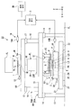
도 1 은 본 실시형태에 따른 노광 장치의 일 예를 도시한 개략 블록도이다.
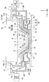
도 2 는 본 실시형태에 따른 제 1 부재 및 제 2 부재의 근방을 도시한 측단면도이다.
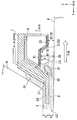
도 3 은 본 실시형태에 따른 제 1 부재 및 제 2 부재의 개략 사시도의 부분 파단도이다.
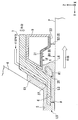
도 4 는 본 실시형태에 따른 제 1 부재 및 제 2 부재를 하측으로부터 본 사시도 (oblique view) 이다.
도 5 는 본 실시형태에 따른 제 1 부재 및 제 2 부재의 부분 확대 측단면도이다.
도 6 은 본 실시형태에 따른 제 1 부재 및 제 2 부재의 동작의 일 예를 설명하기 위한 도면이다.
도 7 은 본 실시형태에 따른 제 1 부재 및 제 2 부재의 동작의 일 예를 설명하기 위한 도면이다.
도 8 은 본 실시형태에 따른 제 1 부재 및 제 2 부재의 동작의 일 예를 설명하기 위한 도면이다.
도 9 는 본 실시형태에 따른 제 1 부재 및 제 2 부재의 동작의 일 예를 설명하기 위한 도면이다.
도 10 은 본 실시형태에 따른 제 1 부재 및 제 2 부재의 동작의 일 예를 설명하기 위한 도면이다.
도 11 은 마이크로디바이스의 제조 공정의 일 예를 나타낸 플로우차트이다.1 is a schematic block diagram showing an example of an exposure apparatus according to the present embodiment.
2 is a side cross-sectional view showing the vicinity of the first member and the second member according to the present embodiment.
3 is a partial cutaway view of a schematic perspective view of the first member and the second member according to the present embodiment.
4 is an oblique view of the first member and the second member according to the present embodiment as seen from below.
5 is a partially enlarged side cross-sectional view of the first member and the second member according to the present embodiment.
6 is a view for explaining an example of the operation of the first member and the second member according to the present embodiment.
7 is a view for explaining an example of the operation of the first member and the second member according to the present embodiment.
8 is a view for explaining an example of the operation of the first member and the second member according to the present embodiment.
9 is a view for explaining an example of the operation of the first member and the second member according to the present embodiment.
10 is a view for explaining an example of the operation of the first member and the second member according to the present embodiment.
11 is a flowchart illustrating an example of a manufacturing process of a microdevice.
이하에, 본 발명의 실시형태를 도면을 참조하여 설명하지만 본 발명은 이것에 한정되지 않는다. 이하의 설명은 XYZ 직교 좌표계를 설정하고, 이 XYZ 직교 좌표계를 참조하여 부재들 간의 위치 관계가 설명된다. 수평면 내의 소정 방향을 X 축 방향으로 하고, 수평면 내에서의 X 축 방향과 직교하는 방향을 Y 축 방향으로 하며, X 축 방향 및 Y 축 방향과 직교하는 방향 (즉, 수직 방향) 을 Z 축 방향으로 한다. 또한, X 축, Y 축 및 Z 축 둘레의 회전 (경사) 방향을 각각 θX 방향, θY 방향 및 θZ 방향으로 한다.EMBODIMENT OF THE INVENTION Below, embodiment of this invention is described with reference to drawings, but this invention is not limited to this. The following description sets the XYZ rectangular coordinate system, and the positional relationship between members is described with reference to this XYZ rectangular coordinate system. The predetermined direction in the horizontal plane is the X axis direction, the direction orthogonal to the X axis direction in the horizontal plane is the Y axis direction, and the direction orthogonal to the X axis direction and the Y axis direction (that is, the vertical direction) is the Z axis direction. It is done. Further, the rotation (tilt) directions around the X, Y, and Z axes are the θX direction, the θY direction, and the θZ direction, respectively.
도 1 은 본 실시형태에 따른 노광 장치 (EX) 의 일 예를 도시한 개략 블록도이다. 도 1 에서, 노광 장치 (EX) 는 마스크 (M) 를 유지하는 이동가능한 마스크 스테이지 (1); 기판 (P) 을 유지하는 이동가능한 기판 스테이지 (2); 마스크 (M) 를 노광 광 (EL) 으로 조명하는 조명계 (IL); 노광 광 (EL) 에 의해 조명되는 마스크 (M) 의 패턴의 이미지를 기판 (P) 에 투영하는 투영 광학계 (PL); 및 노광 장치 (EX) 전체의 동작을 제어하는 제어 장치 (3) 를 포함한다. 또한, 노광 장치 (EX) 는 제어 장치 (3) 에 접속되고 예를 들어 노광 장치 (EX) 의 동작 상황을 출력할 수 있는 출력 장치 (3D) 를 포함한다. 출력 장치 (3D) 는 평판 디스플레이와 같은 디스플레이 장치; 광을 발하는 광 발생 장치; 및 음 (경보 (alarm) 를 포함) 을 발하는 음 발생 장치 중 적어도 하나를 포함한다.1 is a schematic block diagram illustrating an example of an exposure apparatus EX according to the present embodiment. In FIG. 1, the exposure apparatus EX includes a
마스크 (M) 는 예를 들어, 기판 (P) 에 투영되는 디바이스 패턴이 형성되는 레티클일 수도 있다. 마스크 (M) 는 예를 들어, 유리판과 같은 투명판 상에 크롬 등으로 제조된 차광막을 이용하여 소정 패턴이 형성되는 광투과형 마스크일 수 있다. 또한, 마스크 (M) 는 대안으로 반사형 마스크일 수 있다. 기판 (P) 은 디바이스를 제조하기 위한 기판이다. 기판 (P) 은 기재 (예를 들어, 반도체 웨이퍼, 이를 테면 실리콘 웨이퍼) 및 그 기재 상에 형성되는 감광막을 포함한다. 감광막은 감광 재료 (포토레지스트) 로 제조된다. 감광막에 더하여, 기판 (P) 은 별개의 막을 포함할 수 있다. 예를 들어, 기판 (P) 은 반사방지막, 감광막을 보호하는 보호막 (탑코트막) 등을 포함할 수 있다.The mask M may be, for example, a reticle on which a device pattern projected onto the substrate P is formed. The mask M may be, for example, a light transmissive mask in which a predetermined pattern is formed using a light shielding film made of chromium or the like on a transparent plate such as a glass plate. In addition, the mask M may alternatively be a reflective mask. The substrate P is a substrate for manufacturing a device. The substrate P comprises a substrate (for example, a semiconductor wafer such as a silicon wafer) and a photosensitive film formed on the substrate. The photosensitive film is made of a photosensitive material (photoresist). In addition to the photosensitive film, the substrate P may comprise a separate film. For example, the substrate P may include an antireflection film, a protective film (top coat film) for protecting the photosensitive film, or the like.
본 실시형태에서, 노광 장치 (EX) 는 액체 (LQ) 를 통과하는 노광 광 (EL) 으로 기판 (P) 을 노광하는 액침 노광 장치이다. 본 실시형태에서는, 노광 광 (EL) 의 광로의 적어도 일부가 액체 (LQ) 로 채워지도록 액침 공간 (LS) 이 형성된다. 액침 공간 (LS) 은 액체 (LQ) 로 채워지는 공간이다. 본 실시형태에서는, 액체 (LQ) 로서 물 (순수) 을 이용한다.In the present embodiment, the exposure apparatus EX is a liquid immersion exposure apparatus that exposes the substrate P with exposure light EL passing through the liquid LQ. In this embodiment, the liquid immersion space LS is formed so that at least a part of the optical path of the exposure light EL is filled with the liquid LQ. The liquid immersion space LS is a space filled with the liquid LQ. In this embodiment, water (pure water) is used as the liquid LQ.
본 실시형태에서, 액침 공간 (LS) 은 투영 광학계 (PL) 의 복수의 광학 소자 중, 투영 광학계 (PL) 의 이미지면에 가장 근접한 광학 소자인 종단 광학 소자 (4) 로부터 사출되는 노광 광 (EL) 의 광로 (K) 가 액체 (LQ) 로 채워지도록 형성된다. 종단 광학 소자 (4) 는 투영 광학계 (PL) 의 이미지면을 향하여 노광 광 (EL) 을 방출하는 사출면 (5) 을 갖는다. 액침 공간 (LS) 은 종단 광학 소자 (4) 와 그 종단 광학 소자 (4) 의 사출면 (5) 과 대향하는 위치에 배치되는 물체 사이의 광로 (K) 가 액체 (LQ) 로 채워지도록 형성된다. 물체가 사출면 (5) 과 대향하는 위치는 사출면 (5) 으로부터 사출되는 노광 광 (EL) 의 조사 위치를 포함한다. 이하의 설명에서, 물체가 종단 광학 소자 (4) 의 사출면 (5) 과 대향하는 위치는 적절히 노광 위치로 불린다.In the present embodiment, the immersion space LS is the exposure light EL emitted from the terminal
노광 장치 (EX) 는 종단 광학 소자 (4) 와 그 종단 광학 소자 (4) 의 사출면 (5) 과 대향하는 위치에 배치되는 물체 사이의 광로 (K) 를 액체 (LQ) 로 채우기 위한 액침 시스템을 포함한다. 액침 시스템은 사출면 (5) 으로부터 방출되는 노광 광 (EL) 의 광로 (K) 주위에 배치되고, 노광 위치에 배치되는 물체의 표면과의 사이에 액체 (LQ) 를 유지할 수 있는 하면 (6) 을 갖는 제 1 부재 (7); 노광 광 (EL) 의 광로 (K) 에 대하여 하면 (6) 의 외측 주위에 배치되고, 물체의 표면 상의 액체 (LQ) 를 회수할 수 있는 액체 회수구 (8) 를 갖는 제 2 부재 (9); 제 1 부재 (7) 를 이동시킬 수 있는 제 1 구동 장치 (11); 및 제 1 부재 (7) 와 독립적으로 제 2 부재 (9) 를 이동시킬 수 있는 제 2 구동 장치 (12) 를 포함한다.The exposure apparatus EX is a liquid immersion system for filling the optical path K with the liquid LQ between the terminal
제 1 부재 (7) 는 종단 광학 소자 (4) 근방에 배치된다. 본 실시형태에서, 사출면 (5) 과 대향할 수 있는 물체는 또한 하면 (6) 과 대향할 수 있다. 물체의 표면이 사출면 (5) 과 대향하는 위치에 배치되는 경우, 하면 (6) 의 적어도 일부와 물체의 표면이 대향된다. 사출면 (5) 과 물체의 표면이 대향되는 경우, 사출면 (5) 과 물체의 표면 사이의 공간은 액체 (LQ) 를 유지할 수 있다. 또한, 하면 (6) 과 물체의 표면이 대향되는 경우, 하면 (6) 과 물체의 표면 사이의 공간은 액체 (LQ) 를 유지할 수 있다. 사출면 (5) 과 일측의 하면 (6) 및 타측의 물체의 표면 사이에 액체 (LQ) 를 유지하는 것은 종단 광학 소자 (4) 의 사출면 (5) 과 물체의 표면 사이의 노광 광 (EL) 의 광로 (K) 가 액체 (LQ) 로 채워지도록 액침 공간 (LS) 을 형성한다.The
본 실시형태에서, 사출면 (5) 은 -Z 방향으로 향한다. 하면 (6) 은 -Z 방향으로 향한다. 액체 회수구 (8) 의 적어도 일부는 -Z 방향으로 향한다. 사출면 (5) 및 하면 (6) 과 대향할 수 있고 사출면 (5) 및 하면 (6) 과의 사이에 액체 (LQ) 를 유지할 수 있는 물체의 표면의 적어도 일부는 +Z 방향으로 향한다.In the present embodiment, the
본 실시형태에서, 사출면 (5) 및 하면 (6) 과 대향할 수 있는 물체는 종단 광학 소자 (4) 의 사출 측 (이미지면 측) 에서 이동할 수 있는 물체 및 노광 위치를 포함하는 소정 면 내를 이동할 수 있는 물체를 포함할 수 있다. 본 실시형태에서, 물체는 기판 스테이지 (2) 또는 기판 스테이지 (2) 에 의해 유지되는 기판 (P) 중 적어도 하나, 또는 양자를 포함한다. 또한, 설명을 단순화하기 위해, 이하에는 주로 종단 광학 소자 (4) 의 사출면 (5) 과 기판 (P) 이 대향하는 일 예시적인 상태를 설명한다.In the present embodiment, an object that can oppose the emitting
노광 장치 (EX) 는 예를 들어 클린룸 내부의 지지면 (FL) 상에 제공되는 제 1 컬럼 (10A); 및 제 1 컬럼 (10A) 상에 제공되는 제 2 컬럼 (10B) 을 포함하는 바디 (10) 를 포함한다. 제 1 컬럼 (10A) 은 복수의 제 1 지주 (support port) (13); 및 그 제 1 지주 (13) 에 의해 방진 장치 (14) 를 통해 지지되는 제 1 정반 (base plate) (15) 을 포함한다. 제 2 컬럼 (10B) 은 제 1 정반 (15) 상에 제공되는 복수의 제 2 지주 (16); 및 그 제 2 지주 (16) 에 의해 방진 장치 (17) 를 통해 지지되는 제 2 정반 (18) 을 포함한다.The exposure apparatus EX includes, for example, a
조명계 (IL) 는 소정의 조명 영역 (IR) 을 균일한 조도 분포를 갖는 노광 광 (EL) 으로 조명한다. 조명계 (IL) 는 조명 영역 (IR) 에 배치된 마스크 (M) 의 적어도 일부를 균일한 조도 분포를 갖는 노광 광 (EL) 으로 조명한다. 조명계 (IL) 로부터 방출되는 노광 광 (EL) 으로서 사용될 수 있는 광의 예로는, 예를 들어 수은 램프로부터 방출되는 휘선 (g-선, h-선 또는 i-선) 광 및 KrF 엑시머 레이저 광 (파장 248nm) 과 같은 원자외 (DUV; deep ultraviolet) 광; 및 ArF 엑시머 레이저 광 (파장 193nm) 및 F2 레이저 광 (파장 157nm) 과 같은 진공 자외 (VUV; vacuum ultraviolet) 광을 들 수 있다. 본 실시형태에서는, 노광 광 (EL) 으로서 자외 광 (진공 자외 광) 인 ArF 엑시머 레이저 광이 이용된다.The illumination system IL illuminates the predetermined illumination region IR with exposure light EL having a uniform illuminance distribution. The illumination system IL illuminates at least a part of the mask M disposed in the illumination region IR with the exposure light EL having a uniform illuminance distribution. Examples of the light that can be used as the exposure light EL emitted from the illumination system IL include, for example, bright (g-ray, h-ray or i-ray) light and KrF excimer laser light (wavelength) emitted from a mercury lamp. Deep ultraviolet (DUV) light, such as 248 nm); And vacuum ultraviolet (VUV) light such as ArF excimer laser light (wavelength 193 nm) and F 2 laser light (wavelength 157 nm). In this embodiment, ArF excimer laser light which is ultraviolet light (vacuum ultraviolet light) is used as exposure light EL.
마스크 스테이지 (1) 는 마스크 (M) 를 릴리즈가능하게 유지하는 마스크 유지부 (1H) 를 포함한다. 본 실시형태에서, 마스크 유지부 (1H) 는 마스크 (M) 의 패터닝된 면 (하면) 이 XY 평면과 실질적으로 평행이 되도록 마스크 (M) 를 유지한다. 마스크 스테이지 (1) 는 마스크 (M) 를 유지하는 상태에서, 액츄에이터 (예를 들어, 리니어 모터) 를 포함하는 제 1 구동 시스템 (1D) 의 작동에 의해, 조명 영역 (IR) 을 포함하는 XY 평면 내에서 제 2 정반 (18) 의 상면 (가이드면) 을 따라 이동할 수 있다. 제 2 정반 (18) 의 상면은 XY 평면과 실질적으로 평행이다. 본 실시형태에서는, 마스크 스테이지 (1) 는, 마스크 (M) 가 마스크 유지부 (1H) 에 의해 유지되는 상태에서, X 축, Y 축 및 θZ 방향의 3 개의 방향으로 이동할 수 있다.The
간섭계 시스템 (19) 의 레이저 간섭계 (19A) 가 마스크 스테이지 (1) (마스크 (M)) 의 위치를 계측한다. 레이저 간섭계 (19A) 는 마스크 스테이지 (1) 에 제공되는 반사 미러 (1R) 를 이용하여 위치를 계측한다. 레이저 간섭계 (19A) 의 계측 결과에 기초하여, 제어 장치 (3) 는 제 1 구동 시스템 (1D) 을 작동시킴으로써 마스크 스테이지 (1) 에 의해 유지되는 마스크 (M) 의 위치를 제어한다.The
투영 광학계 (PL) 는 소정의 투영 영역 (PR) 에 노광 광 (EL) 을 조사한다. 투영 광학계 (PL) 는 투영 영역 (PR) 에 배치되는 기판 (P) 의 적어도 일부에, 마스크 (M) 의 패턴의 이미지를 소정의 투영 배율로 투영한다. 투영 광학계 (PL) 의 복수의 광학 소자를 렌즈 배럴 (20) 이 유지한다. 렌즈 배럴 (20) 은 플랜지 (20F) 를 갖는다. 투영 광학계 (PL) 는 플랜지 (20F) 를 통해 제 1 정반 (15) 에 의해 지지된다. 제 1 정반 (15) 에 의해 지지되고 종단 광학 소자 (4) 를 포함하는 투영 광학계 (PL) 의 위치는 실질적으로 고정된다. 또한, 제 1 정반 (15) 과 렌즈 배럴 (20) 사이에 방진 장치가 제공될 수 있다. 본 실시형태의 투영 광학계 (PL) 는 예를 들어 1/4, 1/5 또는 1/8 의 투영 배율을 갖는 축소계이다. 또한, 투영 광학계 (PL) 는 등배계 (unity magnification system) 또는 확대계 (enlargement system) 일 수도 있다. 본 실시형태에서는, 투영 광학계 (PL) 의 광축 (AX) 이 Z 축과 평행이다. 또한, 투영 광학계 (PL) 는 반사광학 소자 (catoptric element) 를 포함하지 않는 굴절계 (dioptric system), 굴절광학 소자 (dioptric element) 를 포함하지 않는 반사계 (catoptric system), 또는 반사광학 소자와 굴절광학 소자 양자를 포함하는 반사굴절계 (catadioptric system) 일 수도 있다. 또한, 투영 광학계 (PL) 는 도립상 또는 정립상 중 어느 하나를 형성할 수도 있다.The projection optical system PL irradiates the exposure light EL to the predetermined projection area PR. The projection optical system PL projects the image of the pattern of the mask M on at least a part of the substrate P disposed in the projection area PR at a predetermined projection magnification. The
기판 스테이지 (2) 는 기판 (P) 을 릴리즈가능하게 유지하는 기판 유지부 (2H) 를 포함한다. 본 실시형태에서, 기판 유지부 (2H) 는 기판 (P) 의 표면 (노광면) 이 XY 평면과 실질적으로 평행이 되도록 기판 (P) 을 유지한다. 기판 스테이지 (2) 는 기판 (P) 을 유지하는 상태에서, 액츄에이터 (예를 들어, 리니어 모터) 를 포함하는 제 2 구동 시스템 (2D) 의 작동에 의해, 투영 영역 (PR) 을 포함하는 XY 평면 내에서 제 3 정반 (21) 의 상면 (가이드면) 을 따라 이동할 수 있다. 제 3 정반 (21) 은 방진 장치 (22) 를 통해 지지면 (FL) 에 의해 지지된다. 제 3 정반 (21) 의 상면은 XY 평면과 실질적으로 평행이다. 본 실시형태에서는, 기판 스테이지 (2) 는, 기판 (P) 이 기판 유지부 (2H) 에 의해 유지되는 상태에서, X 축 방향, Y 축 방향 및 Z 축 방향, 및 θX 방향, θY 방향 및 θZ 방향의 6 개의 방향으로 이동할 수 있다.The
기판 스테이지 (2) 는 기판 유지부 (2H) 주위에 배치되고 종단 광학 소자 (4) 의 사출면 (5) 과 대향할 수 있는 상면 (2T) 을 갖는다. 기판 유지부 (2H) 는 기판 스테이지 (2) 에 제공되는 오목부 (recessed part) (2C) 에 배치된다. 기판 유지부 (2H) 에 의해 유지되는 기판 (P) 의 표면은 종단 광학 소자 (4) 의 사출면 (5) 과 대향할 수 있다. 기판 스테이지 (2) 의 상면 (2T) 은 XY 평면과 실질적으로 평행인 평탄면이다. 기판 유지부 (2H) 에 의해 유지되는 기판 (P) 의 표면, 및 기판 스테이지 (2) 의 상면 (2T) 은 실질적으로 동일 평면에 배치된다 (즉, 서로 실질적으로 면일 (面一) 이다). The
간섭계 시스템 (19) 의 레이저 간섭계 (19B) 가 X 축, Y 축 및 θZ 방향에서의 기판 스테이지 (2) (기판 (P)) 의 위치를 계측한다. 레이저 간섭계 (19B) 는 기판 스테이지 (2) 에 제공되는 반사 미러 (2R) 를 이용하여 기판 스테이지 (2) 의 위치를 계측한다. 또한, 검출 시스템 (50) 이 기판 스테이지 (2) 에 의해 유지되는 기판 (P) 의 표면의 (Z 축, θX 방향 및 θY 방향에서의) 위치를 검출한다. 레이저 간섭계 (19B) 의 계측 결과 및 검출 시스템 (50) 의 검출 결과에 기초하여, 제어 장치 (3) 는 제 2 구동 시스템 (2D) 을 작동시킴으로써 기판 스테이지 (2) 에 의해 유지되는 기판 (P) 의 위치를 제어한다.The
본 실시형태에서, 검출 시스템 (50) 은 복수의 검출점에서, 기판 (P) 의 표면 또는 기판 스테이지 (2) 의 상면 (2T), 또는 양자의 높이 (Z 축 방향에서의 위치) 를 검출할 수 있다. 검출 시스템 (50) 은 기판 (P) 의 표면 및 기판 스테이지 (2) 의 상면 (2T) 은 물론, 물체의 표면의 위치를 검출할 수 있다. 또한, 다양한 센서가 검출 시스템 (50) 에 이용될 수 있다. 예를 들어, 기판 (P) 의 표면 또는 기판 스테이지 (2) 의 상면 (2T), 또는 양자에 검출 광이 조사될 수도 있고, 그 반사광을 수광하는 광학 센서가 이용될 수도 있으며, 대안으로는, 커패시턴스 센서가 이용될 수도 있다.In the present embodiment, the
본 실시형태에서, 노광 장치 (EX) 는 마스크 (M) 및 기판 (P) 을 소정의 주사 방향으로 동기 이동시키면서, 마스크 (M) 의 패턴의 이미지를 기판 (P) 에 투영하는 주사형 노광 장치 (소위, 스캐닝 스텝퍼) 이다. 기판 (P) 이 노광될 경우, 제어 장치 (3) 는 마스크 스테이지 (1) 및 기판 스테이지 (2) 를 제어하여 마스크 (M) 및 기판 (P) 을 각각 광축 (AX) (즉, 노광 광 (EL) 의 광로 (K)) 과 교차하는 XY 평면 내의 소정의 주사 방향으로 이동시킨다. 본 실시형태에서, 기판 (P) 과 마스크 (M) 양자의 주사 방향 (동기 이동 방향) 은 Y 축 방향이다. 제어 장치 (3) 는 기판 (P) 을 투영 광학계 (PL) 의 투영 영역 (PR) 에 대하여 Y 축 방향 중 하나로 이동시키며, 그 기판 (P) 의 이동과 동기하여, 조명계 (IL) 의 조명 영역 (IR) 에 대하여 마스크 (M) 를 다른 Y 축 방향으로 이동시키면서 투영 광학계 (PL) 및 기판 (P) 상의 액침 공간 (LS) 내의 액체 (LQ) 를 통하여 기판 (P) 에 노광 광 (EL) 을 조사한다. 이로써, 마스크 (M) 의 패턴의 이미지가 기판 (P) 에 투영되며, 기판 (P) 은 이로써 노광 광 (EL) 에 의해 노광된다.In the present embodiment, the exposure apparatus EX projects the image of the pattern of the mask M onto the substrate P while synchronously moving the mask M and the substrate P in a predetermined scanning direction. (So-called scanning stepper). When the substrate P is exposed, the control device 3 controls the
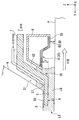
다음에, 액침 시스템의 제 1 부재 (7) 및 제 2 부재 (9) 가 도 2 내지 도 5 를 참조하여 설명될 것이다. 도 2 는 제 1 부재 (7) 및 제 2 부재 (9) 의 근방을 도시하는 측단면도이고; 도 3 은 제 1 부재 (7) 및 제 2 부재 (9) 를 도시하는 개략 사시도의 부분 파단도이고; 도 4 는 제 1 부재 (7) 및 제 2 부재 (9) 를 하측에서 본 사시도이며; 도 5 는 제 1 부재 (7) 및 제 2 부재 (9) 의 부분 확대 측단면도이다.Next, the
또한, 다음에, 종단 광학 소자 (4) 의 사출면 (5) 과 대향하는 위치에 기판 (P) 이 배치되는 일 예시적인 경우를 설명하지만, 상기 논의한 바와 같이, 종단 광학 소자 (4) 의 사출면 (5) 과 대향하는 위치에는 기판 스테이지 (2) 와 같은 기판 (P) 이외의 다른 물체를 배치하는 것이 또한 가능하다.Also, an example case where the substrate P is disposed at a position opposite to the
제 1 부재 (7) 는 직사각형 환상 부재 (직사각형 링 형상 부재) 이다. 제 1 부재 (7) 는 노광 광 (EL) 의 광로 (K) 주위에 배치된다. 본 실시형태에서, 제 1 부재 (7) 는 종단 광학 소자 (4) 주위에 배치되는 측판부 (23), 및 Z 축 방향에 있어서 적어도 일부가 종단 광학 소자 (4) 의 사출면 (5) 과 기판 (P) 의 표면 사이에 배치되는 하판부 (24) 를 포함한다.The
측판부 (23) 는 종단 광학 소자 (4) 의 외주면 (25) 과 대향하고, 그 외주면 (25) 을 따라 형성되는 내주면 (26) 을 갖는다. 제 1 부재 (7) 의 내주면 (26) 은 종단 광학 소자 (4) 의 외주면 (25) 과 소정의 간극 (G1) 을 개재하여 대향하도록 배치된다. 또한, 외주면 (25) 및 내주면 (26) 은 광축 (AX) (즉, 노광 광 (EL) 의 광로 (K)) 에 대한 방사 방향에 있어서 상향으로 경사지게 된다. 즉, 외주면 (25) 및 내주면 (26) 은 각각 광축 (AX) 으로부터 더 많이 이격됨에 따라 기판 (P) 의 표면으로부터의 거리가 점차 증가하도록 제공된다. 외주면 (25) 및 내주면은 각각 외부를 향해 오르는 경사 (upward and outward inclination) 를 갖는다. 본 실시형태에서, 간극 (G1) 의 크기는 액침 공간 (LS) 의 액체 (LQ) 의 적어도 일부가 간극 (G1) 으로 흘러 들어갈 수 있도록 하는 크기이다. 외주면 (25) 및 내주면 (26) 은 광축 (AX) 과 평행일 수도 있다.The
하판부 (24) 는 그 중앙에 개구 (27) 를 갖는다. 종단 광학 소자 (4) 의 사출면 (5) 으로부터 사출되는 노광 광 (EL) 은 개구 (27) 를 통과할 수 있다. 예를 들어, 기판 (P) 의 노광 중에, 종단 광학 소자 (4) 의 사출면 (5) 으로부터 사출되는 노광 광 (EL) 은 개구 (27) 를 통과하고 액체 (LQ) 를 통하여 기판 (P) 의 표면에 조사된다. 본 실시형태에서, 개구 (27) 에서의 노광 광 (EL) 의 단면 형상은 실질적으로 X 축 방향을 길이 방향으로 하는 직사각형 (슬릿 형상) 이다. 노광 광 (EL) 의 단면 형상에 따라, 개구 (27) 는 실질적으로 X 방향 및 Y 방향에서 직사각형 (슬릿 형상) 으로 형성된다. 또한, 개구 (27) 에서의 노광 광 (EL) 의 단면 형상 및 기판 (P) 상의 투영 광학계 (PL) 의 투영 영역 (PR) 의 형상은 실질적으로 유사하다.The
제 1 부재 (7) 는 노광 광 (EL) 의 광로 (K) 주위에 배치되고 -Z 방향으로 향하는 하면 (6) 을 갖는다. 하면 (6) 은 기판 (P) 의 표면과 대향하도록 배치된다. 하면 (6) 은 기판 (P) 의 표면과의 사이에 액체 (LQ) 를 유지할 수 있다. 본 실시형태에서, 하면 (6) 은 평탄하고 기판 (P) 의 표면 (XY 평면) 과 실질적으로 평행이다. 본 실시형태에서, XY 평면 내에서의 하면 (6) 의 외형은 직사각형이다. 본 실시형태에서, 하면 (6) 은 XY 평면에 대하여 경사지게 될 수도 있고, 곡면일 수도 있으며, 등등이다.The
본 실시형태에서, 하면 (6) 은 하판부 (24) 의 하면을 포함한다. 하면 (6) 은 개구 (27) 주위에 배치된다. 제 1 부재 (7) 의 하면 (6) 과 대향하는 위치에 기판 (P) 이 배치되는 경우, 제 1 부재 (7) 는 적어도 하면 (6) 과 기판 (P) 의 표면 사이에 액체 (LQ) 를 유지할 수 있다.In the present embodiment, the
제 2 부재 (9) 는 직사각형 환상 부재이다. 제 2 부재 (9) 는 노광 광 (EL) 의 광로 (K) 주위에 배치된다. 본 실시형태에서, 제 2 부재 (9) 는 제 1 부재 (7) 주위에 배치된다. 제 2 부재 (9) 는 제 1 부재 (7) 의 외주면 (28) 의 일부와 대향하고 그 외주면 (28) 을 따라 형성되는 내주면 (29) 을 갖는다. 제 2 부재 (9) 의 내주면 (29) 과 제 1 부재 (7) 의 외주면 (28) 사이에는 간극 (G2) 이 형성된다. 또한, 외주면 (28) 및 내주면 (29) 은 각각 광축 (AX) (즉, 노광 광 (EL) 의 광로 (K)) 에 대한 방사 방향에 있어서 상향으로 경사지게 된다. 즉, 외주면 (28) 및 내주면 (29) 은 각각 광축 (AX) 으로부터 더 많이 이격됨에 따라 기판 (P) 의 표면으로부터의 거리가 점차 증가하도록 제공된다. 외주면 (28) 및 내주면 (29) 은 각각 외부를 향해 오르는 경사를 갖는다. 본 실시형태에서, 간극 (G2) 의 크기는 액침 공간 (LS) 의 액체 (LQ) 의 적어도 일부가 간극 (G2) 으로 흘러 들어갈 수 있도록 하는 크기이다. 또한, 간극 (G2) 의 크기는 액체 (LQ) 의 표면 장력에 의해 액침 공간 (LS) 으로의 액체 (LQ) 의 침투가 억제되도록 하는 크기일 수도 있다. 외주면 (28) 및 내주면 (29) 은 광축 (AX) 과 평행일 수도 있다.The
제 2 부재 (9) 는 노광 광 (EL) 의 광로 (K) 에 대하여 하면 (6) 의 외측에 배치되고, 적어도 일부가 -Z 방향으로 향하는 액체 회수구 (8) 를 갖는다. 도 5 에서, 액체 회수구 (8) 는 기판 (P) 의 표면과 대향한다. 본 실시형태에서, 액체 회수구 (8) 는 노광 광 (EL) 의 광로 (K) 주위에 배치된다. 액체 회수구 (8) 는 기판 (P) 상에 존재하는 액체 (LQ) 를 회수할 수 있다. 액체 회수구 (8) 와 그와 대향되는 기판 (P) 의 표면 사이의 액체 (LQ) 의 적어도 일부는 액체 회수구 (8) 를 통해 회수된다.The
본 실시형태에서, 액체 회수구 (8) 는 적어도 일부가 -Z 방향으로 향하는 액체 회수면 (30) 을 갖는다. 본 실시형태에서, 다공 부재 (34) 가 액체 회수구 (8) 에 배치되며, 다공 부재 (34) 의 표면이 액체 회수면 (30) 을 형성한다. 액체 회수면 (30) 은 노광 광 (EL) 의 광로 (K) 주위에 배치된다. 본 실시형태에서, 다공 부재 (34) 는 판 형상 부재이며, 액체 회수면 (30) 은 하나의 다공 부재 (34) (그 단일 시트) 로부터 형성된다. 본 실시형태에서, 다공 부재 (34) 는 만곡된 부분을 갖는다. 또한, 본 실시형태에서, 다공 부재 (34) 는 플레이트에 복수의 홀 (스루 홀) 이 형성된 것이지만, 다공성 부재 (34) 로서 복수의 홀 (구멍 (pore)) 이 형성되는 소결 부재 (예를 들어, 소결 금속), 발포 부재 (foam member) (예를 들어, 발포 금속) 등이 이용될 수도 있다.In the present embodiment, the
액체 회수면 (30) 은 노광 광 (EL) 의 광로 (K) 에 대하여 하면 (6) 의 외측에 배치된다. 액체 회수면 (30) 은 그 액체 회수면 (30) 과 기판 (P) 의 표면 사이의 액체 (LQ) 를 회수할 수 있다. 액체 회수면 (30) (즉, 액체 회수구 (8)) 과, 그 액체 회수면 (30) 과 대향하는 기판 (P) 의 표면 사이의 액체 (LQ) 의 적어도 일부는 다공 부재 (34) 를 통해 회수된다. 액체 회수면 (30) 은 (즉, 다공 부재 (34) 의 표면) 에서) 액체 회수면 (30) 과 접촉하는 액체 (LQ) 를 회수할 수 있다.The
액체 회수면 (30) 은 하면 (6) 의 주위에 배치되고 -Z 방향으로 향하는 제 1 액체 회수면 (31); 제 1 액체 회수면 (31) 주위에 배치되고 -Z 방향과 다른 방향으로 향하는 제 2 액체 회수면 (32); 및 제 2 액체 회수면 (32) 주위에 배치되고 -Z 방향으로 향하는 제 3 액체 회수면 (33) 을 갖는다. 제 1 액체 회수면 (31), 제 2 액체 회수면 (32) 및 제 3 액체 회수면 (33) 각각은 다공 부재 (34) 의 표면을 포함한다. 또한, 제 1 액체 회수면 (31) 과 제 3 액체 회수면 (33) 사이의 영역 (즉, 제 2 액체 회수면 (32) 이 형성되는 영역) 은 액체 (LQ) 를 회수하지 않는 비-액체 회수면으로서 기능할 수도 있다.The
본 실시형태에서, 제 1 액체 회수면 (31) 및 제 3 액체 회수면 (33) 은 하면 (6) 과 실질적으로 평행이다. 즉, 제 1 액체 회수면 (31) 및 제 3 액체 회수면 (33) 은 기판 (P) 의 표면 (XY 평면) 과 실질적으로 평행이다. 또한, 도 5 에 도시한 바와 같이, 본 실시형태에서는, Z 축 방향에서의 제 1 액체 회수면 (31) 과 기판 (P) 의 표면 사이의 거리 (B1) 가 Z 축 방향에서의 제 3 액체 회수면 (33) 과 기판 (P) 의 표면 사이의 거리 (B2) 보다 크다. 또한, 본 실시형태에서, 제 2 액체 회수면 (32) 은 광축 (AX) (즉, 노광 광 (EL) 의 광로 (K)) 에 대한 방사 방향에 있어서 하향으로 경사지게 된다. 즉, 제 2 액체 회수면 (32) 은 그 제 2 액체 회수면 (32) 이 광축 (AX) 으로부터 더 많이 이격됨에 따라 기판 (P) 의 표면과의 사이의 간격이 점차 작아지도록 제공된다. 제 2 액체 회수면 (32) 은 외부로의 하향경사 (outward declination) (외부를 향해 내려가는 경사 (downward and outward inclination)) 를 갖는다. 또한, 하면 (6) 과 기판 (P) 의 표면 사이의 거리 (A) 는 사출면 (5) 과 기판 (P) 의 표면 사이의 거리 (E) 보다 작다.In the present embodiment, the first
도 5 에서는, Z 축 방향에서의 하면 (6) 과 기판 (P) 의 표면 사이의 거리 (A) 가 Z 축 방향에서의 제 1 액체 회수면 (31) 과 기판 (P) 의 표면 사이의 거리 (B1) 보다 작다. 따라서, 기판 (P) 의 표면에 대하여 제 1 액체 회수면 (31) 이 하면 (6) 으로부터 이격되는 경우, 하면 (6) 과 제 1 액체 회수면 (31) 사이에는 단차 (35) 가 형성된다. 단차 (35) 는 노광 광 (EL) 의 광로 (K) 에 대하여 제 1 부재 (7) 의 외측에 형성된다. 따라서, 기판 (P) 의 표면에 대하여 +Z 방향으로 움푹 들어가게 되는 오목부 (36) 가 노광 광 (EL) 의 광로 (K) 에 대하여 하면 (6) 의 외측에 형성된다. 오목부 (36) 는 외주면 (28) 의 일부, 제 1 액체 회수면 (31) 및 제 2 액체 회수면 (32) 에 의해 규정된다.In FIG. 5, the distance A between the
제 1 구동 장치 (11) 는 적어도 Z 축 방향과 평행으로 (또는 Z 축 방향을 따라 또는 Z 축 방향으로) 제 1 부재 (7) 를 구동시킬 수 있다. 본 실시형태에서, 제 1 부재 (7) 의 Z 축 방향으로의 이동과 함께, 제 1 부재 (7) 의 하면 (6) 은 Z 축 방향으로 이동한다. 다른 실시형태에서, 제 1 부재 (7) 의 하면 (6) 은 제 1 부재 (7) 의 Z 축 방향과 다른 방향으로의 이동과 함께, 제 1 부재 (7) 의 실질적인 회전과 함께, 또는 제 1 부재 (7) 의 변형과 함께 Z 축 방향으로 이동할 수 있다. 도 2 에 도시한 바와 같이, 본 실시형태에서, 제 1 구동 장치 (11) 는 제 1 정반 (15) (제 1 컬럼 (10A)) 에 배치되는, 액츄에이터, 예를 들어, 보이스 코일 모터를 포함하는 구동 메커니즘 (11A); 및 각각이 제 1 부재 (7) 에 그 대응하는 구동 메커니즘 (11A) 을 접속하는 접속 부재 (11B) 를 포함한다. 제어 장치 (3) 는 구동 메커니즘 (11A) 을 작동시킴으로써 접속 부재 (11B) 에 접속되는 제 1 부재 (7) 를 +Z 방향 및 -Z 방향 양자로 이동시킬 수 있다.The
제 2 구동 장치 (12) 는 제 1 부재 (7) 와 독립적으로 적어도 Z 축 방향과 평행으로 (또는 Z 축 방향을 따라 또는 Z 축 방향으로) 제 2 부재 (9) 를 구동시킬 수 있다. 본 실시형태에서, 제 2 부재 (9) 의 Z 축 방향으로의 이동과 함께, 액체 회수구 (8) (즉, 액체 회수면 (30)) 는 Z 축 방향으로 이동한다. 다른 실시형태에서, 액체 회수구 (8) (즉, 액체 회수면 (30)) 는 제 2 부재 (9) 의 Z 축 방향과 다른 방향으로의 이동과 함께, 제 2 부재 (9) 의 실질적인 회전과 함께, 또는 제 2 부재 (9) 의 변형과 함께 Z 축 방향으로 이동할 수 있다. 본 실시형태에서, 제 2 구동 장치 (12) 는 제 1 정반 (15) (제 1 컬럼 (10A)) 에 배치되는, 액츄에이터, 이를 테면 보이스 코일 모터를 포함하는 구동 메커니즘 (12A); 및 구동 메커니즘 (12A) 과 제 2 부재 (9) 를 접속하는 접속 부재 (12B) 를 포함한다. 제어 장치 (3) 는 구동 메커니즘 (12A) 을 작동시킴으로써 접속 부재 (12B) 에 접속되는 제 2 부재 (9) 를 +Z 방향 및 -Z 방향 양자로 이동시킬 수 있다.The
제어 장치 (3) 는 제 1 구동 장치 (11) 및 제 2 구동 장치 (12) 를 제어할 수 있다. 제어 장치 (3) 는 제 1 구동 장치 (11) 및 제 2 구동 장치 (12) 중 적어도 하나를 작동시킴으로써, Z 축 방향에 있어서, 하면 (6) 과 액체 회수구 (8) (즉, 액체 회수면 (30)) 를 상대 이동시킬 수 있다.The control device 3 can control the
제어 장치 (3) 는 제 1 구동 장치 (11) 를 작동시킴으로써 Z 축 방향에서의 하면 (6) 과 기판 (P) 의 표면 사이의 위치 관계를 조정할 수 있고, 제 2 구동 장치 (12) 를 작동시킴으로써 Z 축 방향에서의 액체 회수구 (8) (즉, 액체 회수면 (30)) 와 기판 (P) 의 표면 사이의 위치 관계를 조정할 수 있다. Z 축 방향에서의 하면 (6) 과 기판 (P) 의 표면 사이의 위치 관계의 조정은 Z 축 방향에서의 하면 (6) 과 기판 (P) 의 표면 사이의 거리 (A) 의 조정을 포함한다. 또한, Z 축 방향에서의 액체 회수구 (8) (즉, 액체 회수면 (30)) 와 기판 (P) 의 표면 사이의 위치 관계의 조정은 Z 축 방향에서의 액체 회수구 (8) (즉, 액체 회수면 (30)) 와 기판 (P) 의 표면 사이의 거리 (B) 의 조정을 포함한다. Z 축 방향에서의 액체 회수구 (8) (즉, 액체 회수면 (30)) 와 기판 (P) 의 표면 사이의 거리 (B) 의 조정은, Z 축 방향에서의 제 1 액체 회수면 (31) 과 기판 (P) 의 표면 사이의 거리 (B1) 의 조정; 및 Z 축 방향에서의 제 3 액체 회수면 (33) 과 기판 (P) 의 표면 사이의 거리 (B2) 의 조정 중 적어도 하나를 포함한다.The control device 3 can adjust the positional relationship between the
또한, 제어 장치 (3) 는 제 1 구동 장치 (11) 를 작동시킴으로써 Z 축 방향에서의 사출면 (5) 과 하면 (6) 사이의 위치 관계를 조정할 수 있고, 제 2 구동 장치 (12) 를 작동시킴으로써 Z 축 방향에서의 사출면 (5) 과 액체 회수구 (8) (즉, 액체 회수면 (30)) 사이의 위치 관계를 조정할 수 있다. Z 축 방향에서의 사출면 (5) 과 하면 (6) 사이의 위치 관계의 조정은 Z 축 방향에서의 사출면 (5) 과 하면 (6) 사이의 거리 (C) 의 조정을 포함한다. Z 축 방향에서의 사출면 (5) 과 액체 회수구 (8) (즉, 액체 회수면 (30)) 사이의 위치 관계의 조정은 Z 축 방향에서의 사출면 (5) 과 액체 회수구 (8) (즉, 액체 회수면 (30)) 사이의 거리 (D) 의 조정을 포함한다. 본 실시형태에서, 거리 (D) 는 Z 축 방향에 있어서 사출면 (5) 과 제 1 액체 회수면 (31) 사이의 거리 (D1) 및 사출면 (5) 과 제 3 액체 회수면 (33) 사이의 거리 (D2) 를 포함한다.In addition, the control device 3 can adjust the positional relationship between the
본 실시형태에서, Z 축 방향에서의 사출면 (5) 과 하면 (6) 사이의 거리 (C) 의 조정은 Z 축 방향에서의 하면 (6) 과 기판 (P) 의 표면 사이의 거리 (A) 의 조정을 포함한다. 또한, Z 축 방향에서의 사출면 (5) 과 액체 회수구 (8) (즉, 액체 회수면 (30)) 사이의 거리 (D) 의 조정은 Z 축 방향에서의 액체 회수구 (8) (즉, 액체 회수면 (30)) 와 기판 (P) 의 표면 사이의 거리 (B) 의 조정을 포함한다. 상기 논의한 바와 같이, 제 1 정반 (15) 에 의해 지지되는 투영 광학계 (PL) 의 종단 광학 소자 (4) 의 위치는 실질적으로 고정된다. 또한, 예를 들어, 기판 (P) 을 노광하는 정규 동작 중에는, 기판 (P) 의 표면 (노광면) 이 투영 광학계 (PL) 의 이미지면과 소정의 위치 관계를 갖도록 (즉, 일치하도록) Z 축, θX 방향 및 θY 방향으로 이동될 수도 있지만; 그 이동량은 극도로 작다. 즉, 기판 (P) 을 노광하는 정규 동작 중에, Z 축 방향에서의 사출면 (5) 과 기판 (P) 의 표면 사이의 거리 (E) 는 미리 실질적으로 결정되며 그 거리 (E) 의 변화량은 극도로 작다. 따라서, 본 실시형태에서, 사출면 (5) 과 하면 (6) 사이의 거리 (C) 의 조정은 하면 (6) 과 기판 (P) 의 표면 사이의 거리 (A) 의 조정과 실질적으로 동일하며; 또한 사출면 (5) 과 액체 회수구 (8) (즉, 액체 회수면 (30)) 사이의 거리 (D) 의 조정은 액체 회수구 (8) (즉, 액체 회수면 (30)) 와 기판 (P) 의 표면 사이의 거리 (B) 의 조정과 실질적으로 동일하다.In this embodiment, the adjustment of the distance C between the
따라서, 본 실시형태에서, 제어 장치 (3) 는 사출면 (5) 과 하면 (6) 사이의 거리 (C) 를 조정함으로써 하면 (6) 과 기판 (P) 의 표면 사이의 거리 (A) 를 조정할 수 있고, 사출면 (5) 과 액체 회수구 (8) (즉, 액체 회수면 (30)) 사이의 거리 (D) 를 조정함으로써 액체 회수구 (8) (즉, 액체 회수면 (30)) 와 기판 (P) 의 표면 사이의 거리 (B) 를 조정할 수 있다.Therefore, in the present embodiment, the controller 3 adjusts the distance A between the
또한, 제어 장치 (3) 는 제 1 구동 장치 (11) 및 제 2 구동 장치 (12) 중 적어도 하나를 작동시킴으로써 제 1 부재 (7) 의 하면 (6) 과 제 2 부재 (9) 의 제 1 액체 회수면 (31) 사이의 위치 관계를 조정할 수 있다. Z 축 방향에서의 하면 (6) 과 제 1 액체 회수면 (31) 사이의 위치 관계의 조정은 Z 축 방향에서의 하면 (6) 과 제 1 액체 회수면 (31) 사이의 거리 (F) (단차 (35) 의 크기) 의 조정을 포함한다.In addition, the control device 3 operates the at least one of the
도 5 에 도시된 상태에서, 거리 (C) 는 거리 (D1) 와 상이하지만, 거리 (D2) 와 동일하다.In the state shown in FIG. 5, the distance C is different from the distance D1, but is the same as the distance D2.
또한, 본 실시형태에서, 도 5 에 도시한 바와 같이, 물체 (여기서, 기판 (P)) 의 표면은 XY 평면과 실질적으로 평행이고 투영 광학계 (PL) 의 이미지면과 실질적으로 일치하도록 배치되며; 또한, 초기 상태는 거리 (A) 와 거리 (B2) 가 동일하고 거리 (A) 와 거리 (C) 가 동일한 상태이다. 이하의 설명에 있어서, 도 5 에 도시된 초기 상태에서의 거리 (A) 를 초기 거리 (A0) 로, 거리 (B) 를 초기 거리 (B0) 로 (여기서, 거리 (B1) 를 초기 거리 (B10) 로, 거리 (B2) 를 초기 거리 (B20) 로), 거리 (C) 를 초기 거리 (C0) 로, 거리 (D) 를 초기 거리 (D0) 로 (여기서, 거리 (D1) 를 초기 거리 (D10) 로, 거리 (D2) 를 초기 거리 (D20) 로), 거리 (E) 를 초기 거리 (E0) 로, 및 거리 (F) 를 초기 거리 (F0) 로 적절히 부른다.In addition, in this embodiment, as shown in FIG. 5, the surface of the object (here, the substrate P) is disposed to be substantially parallel to the XY plane and substantially coincide with the image plane of the projection optical system PL; In addition, the initial state is a state where the distance A and the distance B2 are the same, and the distance A and the distance C are the same. In the following description, the distance A in the initial state shown in FIG. 5 is the initial distance A 0 , the distance B is the initial distance B 0 (wherein the distance B1 is the initial distance). (B1 0 ), distance (B2) to initial distance (B2 0 ), distance (C) to initial distance (C 0 ), distance (D) to initial distance (D 0 ), where distance ( D1) to initial distance (D1 0 ), distance (D2) to initial distance (D2 0 ), distance (E) to initial distance (E 0 ), and distance (F) to initial distance (F 0 ) Call as appropriate.
본 실시형태에서, 제 1 부재 (7) 는 노광 광 (EL) 의 광로 (K) 에 액체 (LQ) 를 공급하는 액체 공급구 (37) 를 갖는다. 액체 공급구 (37) 는 광로 (K) 의 근방에 배치되며 광로 (K) 에 액체 (LQ) 를 공급할 수 있다. 액침 공간 (LS) 을 형성하기 위해, 액체 공급구 (37) 는 사출면 (5) 과 일측의 하면 (6) 및 타측의 기판 (P) 의 표면 사이의 공간에 액체 (LQ) 를 공급할 수 있다.In the present embodiment, the
본 실시형태에서, 액체 공급구 (37) 각각은 -Z 방향과 다른 방향을 향한다. 액체 공급구 (37) 는 노광 광 (EL) 의 광로 (K) 근방에서 그 광로 (K) 에 면하도록 제 1 부재 (7) 에 배치된다.In this embodiment, each of the
본 실시형태에서, 제 1 부재 (7) 는 노광 광 (EL) 의 광로 (K) 주위에 배치되며 사출면 (5) 과 소정의 간극 (G3) 을 개재하여 대향하는 상면 (38) 을 갖는다. 본 실시형태에서, 상면 (38) 은 하판부 (24) 의 상면을 포함한다. 상면 (38) 은 평탄하고 XY 평면과 실질적으로 평행이다. 상면 (38) 은 개구 (27) 주위에 배치된다. 액체 공급구 (37) 는 사출면 (5) 과 상면 (38) 사이의 공간 (39) 에 액체 (LQ) 를 공급할 수 있다. 본 실시형태에서, 액체 공급구 (37) 는 Y 축 방향에서 광로 (K) 의 양측에 (각 측에 하나씩) 배치된다. 이하의 설명에서는, 공간 (39) 을 적절히 내부 공간 (39) 으로 부른다.In the present embodiment, the
도 2 에 도시한 바와 같이, 액체 공급구 (37) 는 유로 (40) 를 통해 액체 공급 장치 (41) 에 접속된다. 액체 공급 장치 (41) 는 온도 조정 장치, 및 질량 유량 제어기 (mass flow controller) 로 불리는 유량 제어 장치를 포함하며, 또한 액체 공급 장치 (41) 는 순수하고 온도 조정된 액체 (LQ) 를 단위 시간 당 소정 양으로 송출할 수 있다. 액체 공급 장치 (41) 는 단위 시간 당의 액체 (LQ) 공급량을 제어할 수 있다. 각 유로 (40) 는 제 1 부재 (7) 의 내부에 형성되는 공급 유로 (40A), 및 공급 유로 (40A) 와 액체 공급 장치 (41) 를 접속하는 공급관으로부터 형성되는 유로 (40B) 를 포함한다. 액체 공급 장치 (41) 로부터 송출되는 액체 (LQ) 는 대응하는 유로 (40) 를 통하여 액체 공급구 (37) 각각에 공급된다. 액체 공급구 (37) 는 액체 공급 장치 (41) 로부터의 액체 (LQ) 를 광로 (K) 에 공급한다.As shown in FIG. 2, the
액체 회수구 (8) 는 유로 (42) 를 통해 액체 회수 장치 (43) 에 접속된다. 액체 회수 장치 (43) 는 진공 시스템을 이용하여 액체 (LQ) 를 흡입함으로써 액체 (LQ) 를 회수할 수 있다. 액체 회수 장치 (43) 는 단위 시간 당의 액체 (LQ) 회수량을 제어할 수 있다. 유로 (42) 는 제 2 부재 (9) 의 내부에 형성되는 회수 유로 (42A), 및 회수 유로 (42A) 와 액체 회수 장치 (43) 를 접속하는 회수관으로부터 형성되는 유로 (42B) 를 포함한다. 본 실시형태에서, 제어 장치 (3) 는 액체 회수 장치 (43) 를 작동시켜 다공 부재 (34) 의 상면과 하면 사이의 압력차를 생성함으로써 다공 부재 (34) (즉, 액체 회수면 (30)) 를 통해 액체 (LQ) 를 회수한다. 액체 회수면 (30) 으로부터 회수되는 액체 (LQ) 는 유로 (42) 를 통하여 액체 회수 장치 (43) 에 의해 회수된다.The
제어 장치 (3) 는 액체 공급 장치 (41) 및 액체 회수 장치 (43) 의 동작을 제어한다. 제어 장치 (3) 는 액체 공급 장치 (41) 를 제어함으로써 액체 공급구 (37) 를 통한 단위 시간 당의 액체 (LQ) 공급량을 조정할 수 있다. 또한, 제어 장치 (3) 는 액체 회수 장치 (43) 를 제어함으로써 액체 회수구 (8) 로부터의 단위 시간 당의 액체 (LQ) 회수량을 조정할 수 있다.The control device 3 controls the operations of the
본 실시형태에서, 제어 장치 (3) 는, 액체 공급구 (37) 로부터의 단위 시간 당의 액체 (LQ) 공급량을 소정 공급량보다 적은 제 1 양으로 설정하는 제 1 모드; 및 액체 공급구 (37) 로부터의 단위 시간 당의 액체 (LQ) 공급량을 소정 공급량보다 많은 제 2 양으로 설정하는 제 2 모드 중 적어도 하나로 액체 공급 장치 (41) 를 설정할 수 있다. 또한, 액체 (LQ) 공급량을 융통성 있게 설정할 수 있게 하기 위한 구성이 채용될 수도 있다.In the present embodiment, the control device 3 includes: a first mode for setting the liquid LQ supply amount per unit time from the
본 실시형태에서, 제어 장치 (3) 는 사출면 (5) 과 대향하는 물체의 표면에서의 액체 (LQ) 의 접촉각 정보 (예를 들어, 후퇴 접촉각 및 히스테리시스) 에 따라 제 1 모드나 제 2 모드 중 어느 하나의 모드를 선택한다. 예를 들어, 제어 장치 (3) 는 기판 스테이지 (2) 에 의해 유지되는 기판 (P) 의 표면에서의 액체 (LQ) 의 접촉각에 따라 제 1 모드나 제 2 모드 중 어느 하나의 모드를 선택한다. 본 실시형태에서, 제어 장치 (3) 는 기판 (P) 의 표면에서의 액체 (LQ) 의 후퇴 접촉각이 비교적 큰 경우 (예를 들어, 후퇴 접촉각이 80°이상인 경우) 에 제 1 모드를 선택하고, 액체 (LQ) 의 후퇴 접촉각이 비교적 작은 경우 (예를 들어, 후퇴 접촉각이 80°미만인 경우) 에 제 2 모드를 선택한다.In the present embodiment, the control device 3 is according to the contact angle information (for example, the receding contact angle and the hysteresis) of the liquid LQ on the surface of the object facing the
또한, 제 1 모드 또는 제 2 모드는 상기 논의된 접촉각 정보 이외의 다른 정보에 기초하여 선택될 수도 있으며, 또는 상기 논의된 접촉각 정보 및 다른 정보 양자에 기초하여 선택될 수도 있다.Further, the first mode or the second mode may be selected based on other information than the contact angle information discussed above, or may be selected based on both the contact angle information and the other information discussed above.
예를 들어, 액체 (LQ) 가 종단 광학 소자 (4) 및/또는 기판 스테이지 (2) (기판 (P)) 에 가하는 힘 (압력), 액체 (LQ) 의 온도 변화 등을 고려할 필요가 있을 수도 있다. 액체 공급구 (37) 로부터의 단위 시간 당의 액체 (LQ) 공급량이 적은 쪽이 종단 광학 소자 (4) 에 대하여 작용하는 액체 (LQ) 의 힘 (압력) 을 감소시킬 수 있다. 또한, 액체 공급구 (37) 로부터의 단위 시간 당의 액체 (LQ) 공급량이 적은 쪽이 또한 기판 (P) 또는 기판 스테이지 (2) 에 대하여 작용하는 액체 (LQ) 의 힘 (압력) 을 감소시킬 수 있다. 또한, 액체 공급구 (37) 로부터의 단위 시간 당의 액체 (LQ) 공급량이 적은 경우, 액체 (LQ) 의 유동이 적기 때문에, 예를 들어 노광 광 (EL) 에 의한 조사로 인한 액체 (LQ) 의 온도 변화 (온도 분포) 가 발생하기 쉬울 것이다.For example, it may be necessary to consider the force (pressure) exerted by the liquid LQ on the terminal
액체 공급구 (37) 로부터의 단위 시간 당의 액체 (LQ) 공급량이 많은 쪽이 예를 들어 노광 광 (EL) 에 의한 조사로 인한 액체 (LQ) 의 온도 변화 (온도 분포) 를 억제할 수 있다. 또한, 액체 공급구 (37) 로부터의 단위 시간 당의 액체 (LQ) 공급량이 많은 경우, 액체 (LQ) 에 의해 종단 광학 소자 (4) 및 기판 스테이지 (2) (기판 (P)) 에 가해지는 힘 (압력) 이 증가할 가능성이 있다.The larger the liquid LQ supply amount per unit time from the
도 3 에 도시한 바와 같이, 본 실시형태에서, 제 1 부재 (7) 는 내부 공간 (39) 및 제 1 부재 (7) (즉, 액침 공간 (LS)) 를 둘러싸는 외부 공간 (44) (즉, 주위 환경) 을 소통시키는 배기구 (45) 를 갖는다. 배기구 (45) 는 내부 공간 (39) 근방에 배치되며 내부 공간 내의 기체를 배기할 수 있다. 본 실시형태에서, 배기구 (45) 는 X 축 방향에서 광로 (K) 의 양측에 (각 측에 하나씩) 제공된다. 배기구 (45) 는 제 1 부재 (7) 의 내부에 형성되는 배기 유로 (46) 에 접속된다. 배기 유로 (46) 의 상단의 개구 (47) 는 외부 공간 (44) 의 기체와 접촉할 수 있는 위치에 배치된다. 외부 공간 (44) 의 기체는 배기 유로 (46) 를 통해 내부 공간 (39) 으로 흘러 들어갈 수 있으며, 내부 공간 (39) 의 기체는 배기 유로 (46) 를 통해 외부 공간 (44) 으로 흘러 나갈 수 있다. 본 실시형태에서, 기체는 내부 공간 (39) 및 그 내부 공간 (39) 의 외측인 외부 공간 (44) (즉, 대기 공간) 사이에서 배기 유로 (46) 를 통해 연속하여 전후로 (back and forth) 흐를 수 있으며, 내부 공간 (39) 은 배기 유로 (46) 를 통해 대기 개방된다.As shown in FIG. 3, in the present embodiment, the
본 실시형태에서, 제 1 부재 (7) 의 하면 (6) 은 액체 (LQ) 에 대하여 친액성 (lyophilic) 이다. 예를 들어, 하면 (6) 과 액체 (LQ) 사이의 접촉각은 40°보다 작고, 바람직하게는 20°보다 작다. 하면 (6) 은 액체 (LQ) 에 대하여 친액성이며, 따라서 기판 (P) 이 X 방향 및 Y 방향으로 이동되는 경우라도 액침 공간 (LS) 의 액체 (LQ) 와의 접촉을 유지할 수 있다. 하면 (6) 은 적어도 기판 (P) 의 노광 중에 액침 공간 (LS) 의 액체 (LQ) 와의 접촉을 유지한다. 또한, 전체 하면 (6) 이 액체 (LQ) 와의 접촉을 유지할 필요는 없지만; 광로 (K) 가 액체 (LQ) 로 채워진 상태를 유지하기 위해, 하면 (6) 의 적어도 일부는 액체 (LQ) 와의 접촉을 유지해야 한다.In the present embodiment, the
또한, 본 실시형태에서, 사출면 (5) 및 하면 (6) 은 기판 (P) 의 표면과의 사이에 액체 (LQ) 를 유지할 수 있으며; 또한 액체 회수면 (30) 의 적어도 일부는 기판 (P) 의 표면과의 사이에 액체 (LQ) 를 유지할 수 있다. 도 2 및 도 5 는 기판 (P) 상의 액체의 일부가 하면 (6) 과 일측의 기판 (P) 및 타측의 액체 회수면 (30) 의 영역의 일부 사이에 유지되는 상태를 도시한다. 예를 들어, 기판 (P) 의 노광 중에, 액침 공간 (LS) 은 하면 (6) 과 일측의 액체 회수면 (30) 및 타측의 기판 (P) 의 표면 사이에 액체 (LQ) 를 유지함으로써 형성된다.Also, in the present embodiment, the ejecting
본 실시형태에서, 액침 공간 (LS) 은 사출면 (5) 및 하면 (6) 과 대향하는 위치에 배치되는 기판 (P) 의 표면의 영역 (국부적 영역) 의 일부가 액체 (LQ) 에 의해 커버되도록 형성되며, 적어도 기판 (P) 의 표면과 액체 회수면 (30) 사이에는 액침 공간 (LS) 의 액체 (LQ) 의 계면 (즉, 메니스커스 또는 에지) (LG) 이 형성된다. 즉, 본 실시형태의 노광 장치 (EX) 는 기판 (P) 의 노광 중에 투영 광학계 (PL) 의 투영 영역 (PR) 을 포함하는 기판 (P) 상의 영역의 일부가 액체 (LQ) 로 커버되도록 액침 공간 (LS) 이 형성되는 국부적 액침 시스템을 채용한다.In the present embodiment, the liquid immersion space LS covers a part of the region (local region) of the surface of the substrate P, which is disposed at a position opposite to the
다음에, 상술된 구성을 갖는 노광 장치 (EX) 를 이용하여 기판 (P) 에 대해 액침 노광을 수행하는 방법을 설명한다.Next, a method of performing liquid immersion exposure on the substrate P using the exposure apparatus EX having the above-described configuration will be described.
제어 장치 (3) 는 액체 공급구 (37) 로부터 광로 (K) 에 액체 (LQ) 를 공급한다. 액체 공급 장치 (41) 로부터 송출되는 액체 (LQ) 는 대응하는 유로 (40) 를 통하여 각 액체 공급구 (37) 에 공급된다. 액체 공급구 (37) 는 내부 공간 (39) 에 액체 (LQ) 를 공급한다. 액체 (LQ) 는 내부 공간 (39) 및 개구 (27) 를 통하여 하면 (6) 과 기판 (P) 의 표면 사이의 공간으로 흘러 들어간다. 또한, 액체 (LQ) 의 적어도 일부는 액체 회수면 (30) 과 기판 (P) 의 표면 사이의 공간으로 흘러 들어간다.The control device 3 supplies the liquid LQ to the optical path K from the
또한, 본 실시형태에서, 제어 장치 (3) 는 액체 공급구 (37) 가 이용되는 액체 공급 동작의 수행과 병행하여, 액체 회수구 (8) (즉, 액체 회수면 (30)) 가 이용되는 액체 회수 동작을 수행한다. 액체 회수면 (30) 과 접촉하는 액체 (LQ) 의 적어도 일부는 액체 회수면 (30) 을 형성하는 다공 부재 (34) 를 통하여 회수된다. 이로써, 종단 광학 소자 (4) 의 사출면 (5) 과 기판 (P) 의 표면 사이의 광로 (K) 가 액체 (LQ) 로 채워지도록 액침 공간 (LS) 이 형성된다.In addition, in the present embodiment, the control device 3 uses the liquid recovery port 8 (i.e., the liquid recovery surface 30) in parallel with performing the liquid supply operation in which the
액침 공간 (LS) 이 형성된 상태에서, 제어 장치 (3) 는 기판 (P) 의 노광을 개시한다. 기판 (P) 상에는 노광 대상 영역인 복수의 샷 영역이 매트릭스로서 배치된다. 기판 (P) 상의 제 1 샷 영역을 노광하기 위해, 제어 장치 (3) 는 종단 광학 소자 (4) 에 대하여 기판 (P) (제 1 샷 영역) 의 표면을 Y 축 방향으로 이동시키면서 투영 광학계 (PL) 및 기판 (P) 상의 액체 (LQ) 를 통하여 제 1 샷 영역을 노광한다. 기판 (P) 상의 제 1 샷 영역의 노광이 완료된 후 제 2 샷 영역의 노광을 개시하기 위해, 제어 장치 (3) 는 액침 공간 (LS) 이 형성된 상태에서 기판 (P) 의 표면이 X 축 방향 중 하나의 방향 (또는 XY 평면 내에서의 X 축 방향에 대하여 경사져 있는 방향) 으로 이동되는 동작 (스텝핑 동작) 을 수행한 후, 제 2 샷 영역을 노광 개시 위치로 이동시킨다. 또한, 제어 장치 (3) 는 제 2 샷 영역의 노광을 개시한다.In the state where the liquid immersion space LS is formed, the control device 3 starts exposure of the substrate P. As shown in FIG. On the board | substrate P, the some shot area | region which is an exposure object area | region is arrange | positioned as a matrix. In order to expose the first shot region on the substrate P, the control device 3 moves the surface of the substrate P (first shot region) with respect to the terminal
제어 장치 (3) 는 종단 광학 소자 (4) 에 대하여 현재의 샷 영역을 Y 축 방향으로 이동시키면서 그 샷 영역을 노광하는 주사 노광 동작; 및 현재의 샷 영역의 노광이 완료된 후에 다음의 샷 영역을 노광 개시 위치로 이동시키는 스텝핑 동작을 반복적으로 수행함으로써 기판 (P) 상의 복수의 샷 영역을 순차적으로 노광한다.The control device 3 includes a scanning exposure operation for exposing the shot area while moving the current shot area with respect to the terminal
본 실시형태에서, 액체 (LQ) 의 온도는 기판 (P) 상의 복수의 샷 영역의 노광 중에 모니터링된다. 본 실시형태에서, 액체 (LQ) 의 온도를 검출할 수 있는 온도 센서가 액체 공급구 (37) 근방, 유로들 (40A) 중 하나; 유로 (40B); 액체 회수구 (8) 근방; 유로 (42A); 및 유로 (42B) 중 하나의 개소에서 액체 (LQ) 와 접촉할 수 있도록 배치된다. 제어 장치 (3) 는 기판 (P) 상의 복수의 샷 영역의 노광 중에 그 온도 센서를 이용하여 액침 공간 (LS) 의 액체 (LQ) 의 온도를 검출한다.In the present embodiment, the temperature of the liquid LQ is monitored during the exposure of the plurality of shot regions on the substrate P. FIG. In the present embodiment, a temperature sensor capable of detecting the temperature of the liquid LQ includes one of the
온도 센서의 검출 결과에 기초하여, 제어 장치 (3) 는 샷 영역 각각에 대해, 관련 샷 영역의 노광 중의 액체 (LQ) 의 온도가 미리 정해진 허용가능한 범위 내에 있는지 여부를 판단한다. 즉, 제어 장치 (3) 는 샷 영역 각각에 대해, 노광 중의 액체 (LQ) 의 온도가 허용가능한 범위 내에 있는지 여부를 입증한다.Based on the detection result of the temperature sensor, the control device 3 determines, for each shot region, whether the temperature of the liquid LQ during exposure of the associated shot region is within a predetermined acceptable range. That is, the control device 3 verifies for each shot region whether the temperature of the liquid LQ during exposure is within an acceptable range.
제어 장치 (3) 가 온도 센서의 검출 결과에 기초하여, 적어도 하나의 샷 영역이 허용가능한 범위 밖의 온도의 액체 (LQ) 를 통하여 노광되었다고 판단한 경우, 기판 (P) 상의 모든 샷 영역의 노광이 완료된 후 및 노광된 기판 (P) 이 기판 스테이지 (2) 로부터 언로드되기 전에, 제어 장치 (3) 는 출력 장치 (3D) 를 이용하여 에러를 출력한다. 에러가 출력되는 경우, 제어 장치 (3) 는 기판 (P) 을 처리하는 동작을 정지하고 액체 (LQ) 의 온도가 허용가능한 범위 내로 돌아올 때까지 대기한다. 이 대기 시간 중에도 물론 제어 장치 (3) 는 온도 센서를 이용하여 액체 (LQ) 의 온도를 모니터링한다. 제어 장치 (3) 가 온도 센서의 결과에 기초하여, 액체 (LQ) 의 온도가 허용가능한 범위 내로 돌아왔다고 판단한 경우, 제어 장치 (3) 는 기판 (P) 을 처리하는 동작을 재개한다.On the basis of the detection result of the temperature sensor, when the control device 3 determines that the at least one shot region is exposed through the liquid LQ at a temperature outside the allowable range, the exposure of all the shot regions on the substrate P is completed. After and before the exposed substrate P is unloaded from the
또한, 제어 장치 (3) 는 기판 (P) 의 노광 중에, 액체 (LQ) 의 온도가 허용가능한 범위 밖에 있다고 판단하는 시점에서, 그 기판 (P) 을 처리하는 동작을 정지 (중단) 할 수 있다.In addition, the control apparatus 3 can stop (stop) the operation | movement which processes the board | substrate P at the time of determining that the temperature of the liquid LQ is outside the allowable range during the exposure of the board | substrate P. FIG. .
본 실시형태에서, 제어 장치 (3) 는 액체 (LQ) 의 공급 조건에 따라 제 1 구동 장치 (11) 및 제 2 구동 장치 (12) 를 이용하여 제 1 부재 (7) 또는 제 2 부재 (9), 또는 양자를 구동하여, Z 축 방향에서의 하면 (6) 과 기판 (P) 의 표면 사이의 위치 관계; 및 Z 축 방향에서의 액체 회수구 (8) (즉, 액체 회수면 (30)) 와 기판 (P) 의 표면 사이의 위치 관계 중 적어도 하나를 조정한다. 또한, 하면 (6) 이나 액체 회수구 (8) (즉, 액체 회수면 (30)) 중 적어도 하나는 액체 (LQ) 의 공급 조건에 따라 이동될 수도 있으며; 또한 하면 (6) 과 액체 회수면 (30) 양자가 이동될 수도 있다. 또한, 하면 (6) 과 액체 회수구 (8) (즉, 액체 회수면 (30)) 양자는 액체 (LQ) 의 공급 조건에 따라 동일한 방향 (+Z 축 방향 또는 -Z 축 방향) 으로 이동될 수도 있으며; 또한 하면 (6) 및 액체 회수면 (30) 은 반대 방향으로 이동될 수도 있다. 또한, 하면 (6) 또는 액체 회수구 (8) (즉, 액체 회수면 (30)), 또는 양자가 액체 (LQ) 의 공급 조건에 따라 이동되는 경우, 하면 (6) 과 액체 회수구 (8) (즉, 액체 회수면 (30)) 사이의 상대 위치가 변화할 수도 있고, 또는 변화하지 않을 수도 있다.In the present embodiment, the control device 3 uses the
Z 축 방향에서의 하면 (6) 과 기판 (P) 의 표면 사이의 위치 관계의 조정은 Z 축 방향에서의 하면 (6) 과 기판 (P) 의 표면 사이의 거리 (A) 의 조정을 포함한다. 또한, Z 축 방향에서의 액체 회수구 (8) (즉, 액체 회수면 (30)) 와 기판 (P) 의 표면 사이의 위치 관계의 조정은 Z 축 방향에서의 액체 회수구 (8) (즉, 액체 회수면 (30)) 와 기판 (P) 의 표면 사이의 거리 (B) 의 조정을 포함한다. 또한, 하면 (6) 과 기판 (P) 의 표면 사이의 거리 (A) 의 조정은 사출면 (5) 과 하면 (6) 사이의 거리 (C) 의 조정을 포함하며, 액체 회수구 (8) (즉, 액체 회수면 (30)) 와 기판 (P) 의 표면 사이의 거리 (B) 의 조정은 사출면 (5) 과 액체 회수구 (8) (즉, 액체 회수면 (30)) 사이의 거리 (D) 의 조정을 포함한다.The adjustment of the positional relationship between the
본 실시형태에서, 제 1 구동 장치 (11) 는 Z 축 방향에서의 구동 메커니즘 (11A) 에 의해 생성되는 구동량을 계측할 수 있는 인코더 시스템을 포함하는 계측 장치 (미도시) 를 포함한다. 계측 장치는 제 1 부재 (7) 에 접속되고 구동 메커니즘 (11A) 에 의해 구동되는 접속 부재 (11B) 의 이동량을 계측할 수 있다. 계측 장치는 또한 Z 축 방향에서 소정의 기준 위치에 대한 접속 부재 (11B) (제 1 부재 (7)) 의 이동량을 계측할 수 있다. 본 실시형태에서는, 이 기준 위치로서 예를 들어, 종단 광학 소자 (4) 의 사출면 (5) 이 이용된다. 계측 장치는 Z 축 방향에서 종단 광학 소자 (4) 의 사출면 (5) 에 대한 제 1 부재 (7) 의 이동량을 계측한다. 계측 장치의 인코더 시스템은 스케일 부재 및 그 스케일 부재 상의 스케일 (격자) 을 검출하는 인코더 헤드를 포함하며; 또한, 스케일 부재 또는 인코더 헤드, 또는 양자의 위치가 고정된다. 스케일 부재 또는 인코더 헤드, 또는 양자는 제 1 정반 (15) 과 같이 위치가 고정되는 고정된 부재에 배치된다. 따라서, 인코더 시스템은 그 고정된 부재에 대한 제 1 부재 (7) 의 위치 (이동량) 를 검출할 수 있다. 또한, 종단 광학 소자 (4) 를 포함하는 투영 광학계 (PL) 는 위치가 고정된 제 1 정반 (15) 에 의해 지지된다. 따라서, 계측 장치는 사출면 (5) 을 기준 위치로서 이용한 제 1 부재 (7) 의 이동량은 물론, 사출면 (5) 에 대한 제 1 부재 (7) 의 하면 (6) 의 위치를 도출할 수 있다.In the present embodiment, the
본 실시형태에서, 제 1 구동 장치 (11) 는 계측 장치의 계측 결과에 기초하여 Z 축 방향에서의 사출면 (5) 에 대한 하면 (6) 의 위치를 조정하며; 즉, 제 1 구동 장치 (11) 는 사출면 (5) 과 하면 (6) 사이의 거리 (C) 를 조정하고 하면 (6) 과 기판 (P) 의 표면 사이의 거리 (A) 를 조정한다.In the present embodiment, the
제 1 구동 장치 (11) 와 유사하게, 제 2 구동 장치 (12) 는 Z 축 방향에서의 구동 메커니즘 (12A) 의 구동량을 계측할 수 있는 계측 장치 (미도시) 를 포함한다. 계측 장치는 제 2 부재 (9) 에 접속되는 접속 부재 (12B) 의 이동량을 계측할 수 있다. 계측 장치는 종단 광학 소자 (4) 의 사출면 (5) 을 기준 위치로서 이용하여 Z 축 방향에서의 제 2 부재 (9) 의 이동량을 계측한다.Similarly to the
본 실시형태에서, 제 2 구동 장치 (12) 는 계측 장치의 계측 결과에 기초하여 Z 축 방향에서의 사출면 (5) 에 대한 액체 회수구 (8) (즉, 액체 회수면 (30)) 의 위치를 조정하며; 즉, 제 2 구동 장치 (12) 는 사출면 (5) 과 액체 회수구 (8) (즉, 액체 회수면 (30)) 사이의 거리 (D) 를 조정하고 액체 회수구 (8) (즉, 액체 회수면 (30)) 와 기판 (P) 의 표면 사이의 거리 (B) 를 조정한다.In this embodiment, the
노광 광 (EL) 의 광로 (K) 를 채우는 액체 (LQ) 의 공급 조건은 광로 (K) 에 대한 단위 시간 당의 액체 (LQ) 공급량을 포함한다. 본 실시형태에서, 액체 (LQ) 의 공급 조건은 또한 선택된 모드, 즉, 상기 논의된 제 1 모드 또는 제 2 모드를 포함한다.The supply conditions of the liquid LQ which fills the optical path K of the exposure light EL include the liquid LQ supply amount per unit time to the optical path K. In this embodiment, the supply conditions of the liquid LQ also include the selected mode, that is, the first mode or the second mode discussed above.
예를 들어, 액체 공급구 (37) 로부터의 단위 시간 당의 액체 (LQ) 공급량을 감소시키길 원하는 경우, 즉, 제 1 모드가 설정되는 경우, 제어 장치 (3) 는 제 1 부재 (7) 의 하면 (6) 과 제 1 액체 회수면 (31) 사이의 거리 (F) 가 초기 거리 (F0) 보다 크도록 제 1 부재 (7) 또는 제 2 부재 (9), 또는 양자를 Z 축 방향으로 이동시킨다. 본 실시형태에서, 제 2 부재 (9) 는 도 6 에 도시한 바와 같이 +Z 방향으로 이동된다. 즉, 제 2 부재 (9) 는 제 1 액체 회수면 (31) 과 기판 (P) 사이의 거리 (B) 가 초기 거리 (B0) 보다 크도록 +Z 방향으로 이동된다. 기판 (P) 이 도 6 에 도시한 바와 같이 종단 광학 소자 (4) 에 대하여 -Y 방향으로 이동되는 경우, 단차 (35) 근방의 액체 (LQ) 는 -Y 방향으로 흐르기 쉽지 않다. 기판 (P) 을 -Y 방향으로 이동시키는 것은, 다르게는 하면 (6) 과 기판 (P) 의 표면 사이에 생성될 -Y 방향으로의 액체 (LQ) 의 임의의 흐름을 (제 1 액체 회수면 (31) 과 기판 (P) 의 표면 사이의) 단차 (35) 에서의 압력 손실의 결과로서 방해한다. 기판 (P) 이 -Y 방향으로 이동되는 경우, 단차 (35) 근방에, 도 6 에 화살표 (R1) 로 도시한 바와 같이, 액체 (LQ) 의 흐름 (과류 (vortex)) 이 생성되어, 액체 (LQ) 의 계면 (LG) 의 -Y 방향으로의 이동이 억제된다. 거리 (B) 의 크기를 증가시켜, 단차 (35) (거리 (F)) 의 크기를 증가시키는 것은 액체 (LQ) 의 계면 (LG) 의 -Y 방향으로의 이동을 보다 효과적으로 억제한다. 그 결과, 간극 (G1) 내의 Z 축 방향에서의 액체 (LQ) 의 표면 (즉, 기액 계면 또는 메니스커스) 의 위치의 -Z 방향으로의 이동이 억제된다 (즉, 수위의 저하가 억제된다). 따라서, 간극 (G1) 에서의 액체 (LQ) 의 표면은 높은 위치에 유지될 수 있다.For example, when it is desired to reduce the liquid LQ supply amount per unit time from the
액체 공급구 (37) 로부터의 단위 시간 당의 액체 (LQ) 공급량이 적고 액체 (LQ) 의 계면 (LG) 이 장거리 이동하는 경우, 그 계면 (LG) 의 이동에 수반하여, 간극 (G1) 내의 Z 축 방향에서의 액체 (LQ) 의 표면의 위치는 -Z 방향으로 이동하기 쉬울 것이다. 즉, 간극 (G1) 에서의 액체 (LQ) 의 레벨 (수위) 이 하강하기 쉬울 것이다. 그 결과, 간극 (G1) 은 기체로 채워질 수도 있고, 종단 광학 소자 (4) 와 기판 (P) 사이의 액체 (LQ) 중에는 기포 또는 보이드, 또는 양자가 혼입될 수도 있다.When the liquid LQ supply amount per unit time from the
본 실시형태에 의하면, 액체 공급구 (37) 로부터의 단위 시간 당의 액체 (LQ) 공급량을 저감시키길 원하는 경우, 단차 (35) (즉, 거리 (F)) 의 크기를 증가시킴으로써 액체 (LQ) 중에의 기포 또는 보이드, 또는 양자의 혼입이 억제될 수 있다.According to this embodiment, when it is desired to reduce the liquid LQ supply amount per unit time from the
또한, 도 6 에 도시된 예에서, 제 2 부재 (9) 의 +Z 방향으로의 이동에 의해 거리 (F) (즉, 단차 (35)) 가 증가되지만, 도 7 에 도시한 바와 같이, 제 1 부재 (7) 가 대신 -Z 방향으로 하강될 수도 있다. 상기 논의한 바와 같이, 액체 공급구 (37) 로부터의 단위 시간 당의 액체 (LQ) 공급량이 적은 경우, 간극 (G1) 에서의 액체 (LQ) 의 표면의 위치가 -Z 방향으로 이동하기 쉽지만, 거리 (A) 를 초기 거리 (A0) 보다 작게 만듦으로써, 제 1 부재 (7) 의 하면 (6) 과 기판 (P) 의 표면 사이의 압력의 손실이 증가되고, 차례로, 액체 (LQ) 의 계면 (LG) 의 이동이 훨씬 더 효과적으로 억제된다. 따라서, 간극 (G1) 에서의 액체 (LQ) 의 레벨의 하강이 억제되며, 이는 액체 (LQ) 의 표면을 높은 위치에 유지하는 것을 가능하게 한다. 제 1 부재 (7) 가 -Z 방향으로 이동되는 경우, 거리 (F) 는 초기 거리 (F0) 보다 커지기 때문에, 제 2 부재 (9) 는 도 7 에 도시한 바와 같이 이동될 필요가 없으며, 또는 제 2 부재 (9) 는 -Z 방향 또는 제 1 부재 (7) 의 이동 방향과 반대 방향인 +Z 방향으로 이동될 수도 있다.In addition, in the example shown in FIG. 6, the distance F (that is, the step 35) is increased by the movement of the
또한, 제 1 모드가 설정되는 경우, 단지 제 1 부재 (7) 를 하강시켜, 거리 (A) 를 초기 거리 (A0) 보다 작게 만듦으로써, 거리 (F) 는 초기 거리 (F0) 보다 커져 거리 (F) 의 크기를 증가시키기 위한 추가 액션이 요구되지 않는다. 즉, 거리 (A) 는 거리 (B2) 와 실질적으로 동일하거나 거리 (B2) 보다 작아질 수도 있다.Further, when the first mode is set, only by lowering the
또한, 예를 들어, 액체 공급구 (37) 로부터의 단위 시간 당의 액체 (LQ) 공급량을 증가시키길 원하는 경우, 즉, 제 2 모드가 설정되는 경우, 도 8 에 도시한 바와 같이, 제어 장치 (3) 는 하면 (6) 과 기판 (P) 의 표면 사이의 거리 (A) 가 초기 거리 (A0) 보다 크도록 제 1 부재 (7) 를 +Z 방향으로 이동시킨다. 거리 (A) 가 작은 상태에서, 즉, 하면 (6) 과 기판 (P) 의 표면 사이의 공간이 작은 상태에서, 액체 공급구 (37) 로부터의 단위 시간 당의 액체 (LQ) 공급량이 증가된 경우, 예를 들어, 간극 (G1) 에서의 액체 (LQ) 의 표면의 위치가 +Z 방향으로 이동하여 (즉, 기액 계면이 상승할 수도 있다), 간극 (G1) 의 상단으로 액체 (LQ) 가 넘쳐흐를 수도 있다.Further, for example, when it is desired to increase the liquid LQ supply amount per unit time from the
본 실시형태에 의하면, 제 2 모드가 설정되는 경우, 하면 (6) 과 기판 (P) 의 표면 사이에서의 압력 손실이 감소하도록 제 1 부재 (7) 를 +Z 방향으로 이동시킴으로써 간극 (G1) 으로 액체 (LQ) 가 넘쳐흐르는 것이 억제될 수 있다. 또한, 제 1 부재 (7) 를 +Z 방향으로 이동시키는 것은 거리 (F) 를 초기 거리 (F0) 보다 작게 만드는데, 이는 단차 (35) 에서의 압력 손실을 감소시키며; 또한, 기판 (P) 의 -Y 축 방향으로의 이동에 수반하여, 액체 (LQ) 의 계면 (LG) 은 -Y 방향으로 이동하기 쉽다. 이로써, 간극 (G1) 에서의 액체 (LQ) 의 레벨의 상승이 억제되며, 차례로, 간극 (G1) 의 상단으로 액체 (LQ) 가 넘쳐흐르는 것이 억제될 수 있다. 또한, 이러한 경우에, 간극 (G2) 도 크기가 증가하기 때문에, 기판 (P) 이 이동할 경우 액침 공간 (LS) 내의 액체 (LQ) 의 적어도 일부가 갭 (G2) 으로 흘러 들어가기 쉬울 것이며, 이 방식으로도, 간극 (G1) 의 상단으로 액체 (LQ) 가 넘쳐흐르는 것이 억제될 수 있다.According to the present embodiment, when the second mode is set, the gap G1 is moved by moving the
또한, 도 8 에 도시된 예에서, 제 1 부재 (7) 는 +Z 방향으로 이동될 수도 있고, 제 2 부재 (9) 는 -Z 방향으로 하강될 수도 있다. 즉, 제 2 부재 (9) 를 -Z 방향으로 하강시킴으로써, 거리 (F) 가 더욱 감소될 수도 있다. 상기 논의한 바와 같이, 액체 공급구 (37) 로부터의 단위 시간 당의 액체 (LQ) 공급량이 많은 경우, 간극 (G1) 의 상단으로 액체 (LQ) 가 넘쳐흐르기 쉽지만; 거리 (F) 를 감소시키는 것은 차례로 단차 (35) 에서의 압력 손실을 감소시키며, 이는 차례로 간극 (G1) 의 상단으로 액체 (LQ) 가 넘쳐흐르는 것을 억제할 수 있다. 또한, 제 3 액체 회수면 (33) 과 기판 (P) 의 표면 사이의 거리 (B2) 가 감소하기 때문에, 즉, 제 3 액체 회수면 (33) 이 기판 (P) 의 표면에 근접하기 때문에, 기판 (P) 상에 박막 또는 액적 (droplet) 으로서 형성된 임의의 액체 (LQ) 도 제 3 액체 회수면 (33) 에 의해 수집될 수 있다.In addition, in the example shown in FIG. 8, the
또한, 제 2 모드가 설정되는 경우에는, 단지 제 1 부재 (7) 를 상승시켜 거리 (A) 를 초기 거리 (A0) 보다 크게 만듦으로써, 거리 (F) 는 초기 거리 (F0) 보다 작아질 필요가 없다.In addition, when the second mode is set, the distance F is smaller than the initial distance F 0 only by raising the
또한, 제 2 모드가 설정되는 경우, 제 1 부재 (7) 는 +Z 방향으로 이동될 필요가 없으며, 즉, 거리 (C) (및, 차례로 거리 (A)) 는 도 5 에 도시한 바와 같이 그 초기 상태로부터 변경될 필요가 없으며, 도 9 에 도시한 바와 같이, 단지 제 1 부재 (7) 의 하면 (6) 과 제 2 부재 (9) 의 제 1 액체 회수면 (31) 사이의 거리 (F) 를 초기 거리 (F0) 보다 작게 만드는 것으로 충분하다. 이 경우에, 단차 (35) 에서의 압력 손실이 감소하는데, 이는 간극 (G1) 의 상단으로 액체 (LQ) 가 흘러 나오는 것을 억제하는 것을 가능하게 한다. 또한, 이 경우에는, 제 3 액체 회수면 (33) 과 기판 (P) 의 표면 사이의 거리 (B2) 가 초기 거리 (B20) 보다 작기 때문에, 도 9 에 도시한 바와 같이 기판 (P) 상에 박막으로서 형성된 임의의 액체 (LQ) 도 제 3 액체 회수면 (33) 에 의해 수집될 수 있다.In addition, when the second mode is set, the
또한, 상기 논의한 바와 같이 액체 (LQ) 의 공급 조건을 고려하여 또는 액체 (LQ) 의 공급 조건을 고려하지 않고, 기판 (P) 의 이동 조건에 따라, Z 축 방향에서의 하면 (6) 과 기판 (P) 의 표면 사이의 위치 관계; 및 Z 축 방향에서의 액체 회수구 (8) (즉, 액체 회수면 (30)) 와 기판 (P) 의 표면 사이의 위치 관계 중 적어도 하나가 조정될 수도 있다. 기판 (P) 의 이동 조건은 XY 평면 내에서의 기판 (P) 의 이동 속도를 포함한다. XY 평면 내에서의 기판 (P) 의 이동 속도는 예를 들어, 주사 노광 중의 Y 축 방향으로의 기판 (P) 의 이동 속도 및 스텝핑 동작 중의 X 축 방향 (또는 XY 평면 내에서의 X 축 방향에 대하여 경사진 방향) 으로의 기판 (P) 의 이동 속도를 포함한다. 또한, 기판 (P) 의 이동 조건은 XY 평면 내에서의 소정 방향으로의 기판 (P) 의 직선적인 연속 이동 거리를 포함한다. XY 평면 내에서의 소정 방향으로의 기판 (P) 의 직선적인 연속 이동 거리는 예를 들어 주사 노광 중의 Y 축 방향으로의 기판 (P) 의 직선적인 연속 이동 거리 및 스텝핑 동작 중의 X 축 방향 (또는 XY 평면 내에서의 X 축 방향에 대하여 경사진 방향) 으로의 기판 (P) 의 직선적인 연속 이동 거리를 포함한다.Further, as discussed above, the
예를 들어, 기판 (P) 이 종단 광학 소자 (4) 에 대하여 -Y 방향으로 고속으로 이동되는 경우, 또는 기판 (P) 이 -Y 방향으로 직선적으로 장거리 이동되는 경우, 제어 장치 (3) 는 제 1 부재 (7) 및 제 2 부재 (9) 를 -Z 방향으로 이동시키며, 이로써 사출면 (5) 과 하면 (6) 사이의 거리 (C) 는 초기 거리 (C0) 보다 커지고, 하면 (6) 과 기판 (P) 의 표면 사이의 거리 (A) 는 초기 거리 (A0) 보다 작아지며, 제 3 액체 회수면 (33) 과 기판 (P) 의 표면 사이의 거리 (B2) 는 초기 거리 (B20) 보다 작아진다. 이로써, 하면 (6) 과 기판 (P) 의 표면 사이에서의 압력 손실이 증가하는데, 이는 기판 (P) 의 이동에 수반하여 액체 (LQ) 의 계면 (LG) 의 이동을 억제하는 것을 가능하게 한다. 또한, 제 3 액체 회수면 (33) 과 기판 (P) 의 표면 사이의 거리 (B2) 가 작기 때문에, 기판 (P) 상의 액체 (LQ) 는 예를 들어 박막 또는 액적을 형성하며, 이 액체 (LQ) 는 또한 제 3 액체 회수면 (33) 에 의해 수집될 수 있다. 또한, 제 1 부재 (7) 및 제 2 부재 (9) 는 하면 (6) 과 제 1 액체 회수면 (31) 사이의 거리 (F) 가 초기 거리 (F0) 보다 커지도록 하강될 수도 있다. 이로써, 하면 (6) 과 제 1 액체 회수면 (31) 사이의 단차 (35) 로 인한 압력 손실이 증가하는데, 이는 기판 (P) 이 이동함에 따라 액체 (LQ) 의 계면 (LG) 의 이동을 보다 효과적으로 억제하는 것을 가능하게 한다. 따라서, 기판 (P) 의 이동 조건에 따라 제 1 부재 (7) 또는 제 2 부재 (9), 또는 양자를 Z 축 방향으로 이동시킴으로써, 제 1 부재 (7) 와 일측의 제 2 부재 (9) 및 타측의 기판 (P) 사이의 공간 밖으로의 액체 (LQ) 의 누출이 억제될 수 있으며, 기판 (P) 의 표면 상에의 액체 (LQ) (즉, 액체 (LQ) 의 막, 액적 등) 의 잔류가 억제될 수 있다.For example, when the substrate P is moved at high speed with respect to the terminal
또한, 도 6 내지 도 9 를 참조하여 설명한 예에서, 하면 (6) 및 액체 회수면 (30) 의 위치는 단일 기판 (P) 의 노광 중에 고정되지만, 하면 (6) 또는 액체 회수면 (30), 또는 양자는 단일 기판 (P) 의 노광 중에 Z 축 방향으로 이동할 수도 있다. 예를 들어, 기판 (P) 의 이동 조건은 그 기판 (P) 의 노광 중에 변화하기 때문에, 다양한 이동 조건에 따라 하면 (6) 또는 액체 회수면 (30), 또는 양자는 Z 축 방향으로 이동할 수도 있다.In addition, in the example described with reference to FIGS. 6 to 9, the positions of the
또한, Z 축 방향에서의 하면 (6) 과 기판 (P) 의 표면 사이의 거리 (A) 또는 액체 회수구 (8) (즉, 액체 회수면 (30)) 와 기판 (P) 의 표면 사이의 거리 (B), 또는 양자는 Z 축 방향에서의 종단 광학 소자 (4) 의 사출면 (5) 과 기판 (P) 의 표면 사이의 거리 (E) 에 따라 제 1 부재 (7) 또는 제 2 부재 (9), 또는 양자를 Z 축 방향으로 이동시킴으로써 조정될 수도 있다.Further, the distance A between the
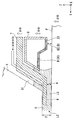
예를 들어, 도 10 에 도시한 바와 같이 기판 (P) 의 표면이 +Z 방향으로 이동되고 거리 (E) 가 감소하는 경우에, 제어 장치 (3) 는 하면 (6) 과 기판 (P) 의 표면 사이의 거리 (A) 및 액체 회수면 (30) 과 기판 (P) 의 표면 사이의 거리 (B) 가 증가하도록 하면 (6) 및 액체 회수면 (30) 의 위치를 조정한다. 그러나, 기판 (P) 의 표면을 +Z 방향으로 이동시키고 거리 (E) 를 감소시키는 것은 하면 (6) 및 액체 회수면 (30) 이 기판 (P) 의 표면과 접촉할 가능성을 야기한다. 예를 들어, 기판 (P) 을 유지하는 기판 스테이지 (2) 의 동작 이상의 결과로서 거리 (E) 가 감소할 수도 있다. 그러나, 거리 (E) 에 따라 Z 축 방향에서의 하면 (6) 및 액체 접촉면 (액체 회수면 (30)) 의 위치를 조정함으로써, 하면 (6) 또는 액체 회수면 (30), 또는 양자의 기판 (P) 과의 접촉 (충돌) 이 억제될 수 있다. 본 실시형태에서, 기판 (P) 의 표면의 위치가 검출 시스템 (50) 에 의해 검출되기 때문에, 제어 장치 (3) 는 예를 들어 기판 스테이지 (2) 에서 동작 이상이 발생하는 경우라도, 검출 시스템 (5) 을 이용하여 기판 (P) 의 표면의 위치를 검출할 수 있으며, 그 검출 결과에 기초하여, 하면 (6) 또는 액체 회수면 (30), 또는 양자의 위치를 조정하여, 하면 (6) 및 액체 회수면 (30) 의 기판 (P) 과의 접촉을 억제할 수 있다.For example, as shown in FIG. 10, when the surface of the substrate P is moved in the + Z direction and the distance E decreases, the control device 3 includes the
또한, 예를 들어, 기판 스테이지 (2) 의 동작 이상의 결과로서, 기판 (P) 의 표면은 -Z 방향으로 이동하여 거리 (E) 를 증가시킬 수도 있다. 이러한 경우에도, 제어 장치 (3) 는 거리 (E) 에 따라 하면 (6) 과 기판 (P) 의 표면 사이의 거리 (A) 또는 액체 회수면 (30) 과 기판 (P) 의 표면 사이의 거리 (B), 또는 양자를 조정할 수 있다. 예를 들어, 기판 (P) 의 표면이 -Z 방향으로 이동하여 거리 (E) 가 증가하는 경우에, 제어 장치 (3) 는 하면 (6) 과 기판 (P) 의 표면 사이의 거리 (A) 및 액체 회수면 (30) 과 기판 (P) 의 표면 사이의 거리 (B) 양자가 감소하도록 제 1 부재 (7) 및 제 2 부재 (9) 를 -Z 방향으로 이동시킨다. 이로써, 기판 (P) 의 표면이 -Z 방향으로 이동하는 경우라도, 하면 (6) 의 위치는 하면 (6) 과 기판 (P) 의 표면 사이에 액체 (LQ) 가 충분히 유지될 수 있도록 조정되며, 액체 회수면 (30) 의 위치는 기판 (P) 상의 액체 (LQ) 가 충분히 회수될 수 있도록 조정된다.Further, for example, as a result of abnormal operation of the
또한, 도 6 내지 도 10 을 참조하여 설명한 예는 기판 (P) 이 노광 위치에 배치되는 경우에 대해 설명하였지만, 상기 논의한 바와 같이, 기판 (P) 이외의 다른 물체가 제 1 부재 (7) 의 하면 및 제 2 부재 (9) 의 액체 회수면 (30) 과 대향하도록 배치되는 경우도 있다. 예를 들어, 기판 스테이지 (2) 의 일부 (상면 (2T)) 가 제 1 부재 (7) 및 제 2 부재 (9) 와 대향하는 위치에 배치될 수도 있다. 이 경우에도, 기판 스테이지 (2) 의 이동 조건 또는 액체 (LQ) 의 공급 조건, 또는 양자에 따라 하면 (6) 또는 액체 회수면 (30), 또는 양자의 위치를 조정함으로써, 액체 (LQ) 의 누출, 잔류 등을 억제하는 것이 가능하다. 또한, 하면 (6) 및 액체 회수면 (30) 과 대향하는 물체와 매칭시키기 위해, 하면 (6) 또는 액체 회수면 (30), 또는 양자의 위치가 변경될 수도 있다. 예를 들어, 기판 (P) 및 기판 스테이지 (2) 의 상면 (2T) 양자가 하면 (6) 및 액체 회수면 (30) 과 대향하는 경우, 하면 (6) 또는 액체 회수면 (30), 또는 양자의 위치는 상이할 수도 있다.In addition, although the example described with reference to FIGS. 6 to 10 has described the case where the substrate P is disposed at the exposure position, as discussed above, an object other than the substrate P may be formed of the
또한, 예를 들어, 기판 (P) 보다 두꺼운 부재가 기판 유지부 (2H) 에 의해 유지될 수도 있다. 대안으로, 기판 스테이지 (2) 의 상면 (2T) 상에, 기판 유지부 (2H) 에 의해 유지되는 기판 (P) 의 표면보다 높은 위치에 부재 (예를 들어, 계측 부재) 가 배치될 수도 있다. 예를 들어, 그 외경이 기판 (P) 의 외경과 실질적으로 동일하지만 기판 (P) 보다 두꺼운 기판형 계측 부재 (예를 들어, 온도 센서) 가 기판 스테이지에 의해 유지되는 경우가 있다. 이러한 부재의 표면과 사출면 (5) 사이의 거리는 초기 거리 (E0) 보다 작기 때문에, 하면 (6) 또는 액체 회수면 (30), 또는 양자는 상기 부재와 접촉할 수도 있다. 이러한 경우에도, Z 축 방향에서의 사출면 (5) 과 부재의 표면 사이의 거리에 따라 하면 (6) 과 부재의 표면 사이의 위치 관계 (거리) 또는 액체 접촉면 (액체 회수면 (30)) 과 부재의 표면 사이의 위치 관계 (거리), 또는 양자를 조정함으로써, 하면 (6) 또는 액체 회수면 (30), 또는 양자의 부재와의 접촉 (충돌) 이 억제될 수 있다. 검출 시스템 (50) 은 부재의 표면의 위치를 검출할 수 있기 때문에, 그 검출 시스템 (50) 의 검출 결과에 기초하여, 제어 장치 (30) 는 하면 (6) 또는 액체 회수면 (30), 또는 양자를 이동시킬 수 있다.Further, for example, a member thicker than the substrate P may be held by the
또한, 노광 장치 (EX) 가, 예를 들어 미국 특허 제6,897,963호에 개시된 바와 같이, 기판 (P) 을 유지하는 이동가능한 기판 스테이지, 및 기준 마크가 형성된 기준 부재 또는 다양한 광전 센서, 또는 양자가 탑재되고 노광될 기판을 유지하지 않는 계측 스테이지를 포함하는 노광 장치인 경우에, 노광 위치에 계측 스테이지가 배치된다. 이 경우에, 하면 (6) 또는 액체 회수면 (30), 또는 양자는 계측 스테이지의 이동 조건 또는 액체 (LQ) 의 공급 조건, 또는 양자에 따라 이동될 수 있다.In addition, the exposure apparatus EX is mounted with a movable substrate stage for holding the substrate P, and a reference member or various photoelectric sensors, or both, on which a reference mark is formed, as disclosed, for example, in US Pat. No. 6,897,963. And an exposure apparatus including a measurement stage that does not hold the substrate to be exposed, the measurement stage is disposed at the exposure position. In this case, the
또한, 하면 (6) 또는 액체 회수면 (30), 또는 양자가 Z 축 방향으로 이동되는 경우, 제어 장치 (3) 는 제 1 구동 장치 (11) 의 계측 장치 및 제 2 구동 장치 (12) 의 계측 장치의 계측 결과에 기초하여, 종단 광학 소자 (4) 및 제 1 부재 (7) 가 서로 접촉하는 것이 억제되고 제 1 부재 (7) 및 제 2 부재 (9) 가 서로 접촉하는 것이 억제되도록, 제 1 부재 (7) 또는 제 2 부재 (9), 또는 양자를 이동시킬 수 있다.In addition, when the
또한, 상기 논의된 실시형태에서, 액침 시스템은 제 1 구동 장치 (11) 및 제 2 구동 장치 (12) 양자를 포함하지만, 제 1 부재 (7) 의 하면 (6) 과 제 2 부재 (9) 의 제 1 액체 회수면 (31) 사이의 상대적인 위치 관계, 즉, Z 축 방향에서의 하면 (6) 과 제 1 액체 회수면 (31) 사이의 거리 (F) (단차 (35) 의 크기) 가 조정되는 한, 제 1 구동 장치 (11) 와 제 2 구동 장치 (12) 중 단 하나만을 포함할 수도 있다.Also, in the embodiment discussed above, the liquid immersion system includes both the
또한, 상기 논의된 실시형태에서는, 2 개의 부재 (제 1 부재 (7) 및 제 2 부재 (9)) 가 Z 축 방향으로 독립적으로 이동될 수 있는 구성이 채용되지만, 3 개 이상의 부재가 Z 축 방향으로 독립적으로 이동될 수 있는 구성이 채용될 수도 있다. 예를 들어, 제 3 액체 회수면 (33) 을 제 1 부재 (9) 에 제공하는 대신에, 제 2 부재 (9) 와는 상이한 제 3 부재에 제공하고, 제 1 부재 (7), 제 2 부재 (9) 및 제 3 부재가 Z 축 방향으로 독립적으로 이동될 수 있는 구성이 채용될 수도 있다.In addition, in the embodiment discussed above, a configuration in which two members (the
또한, 상기 논의된 실시형태 각각에서, 제 1 부재 (7) 또는 제 2 부재 (9), 또는 양자가 XY 평면과 평행으로 이동할 수 있는 구성이 채용될 수도 있다.In addition, in each of the embodiments discussed above, a configuration may be employed in which the
또한, 상기 논의된 실시형태에서, "환상" 은 또한, 직사각형 환상, 원형링 형상, 및 다각형 환상과 같은 다양한 형상을 포함할 수 있다.In addition, in the embodiments discussed above, “annular” may also include various shapes such as rectangular annular, circular ring shaped, and polygonal annular.
상기 설명한 바와 같이, 본 실시형태는, 액체 (LQ) 중에의 기포의 혼입, 액체 (LQ) 의 누출, 또는 잔류를 억제함으로써 노광 불량의 발생을 억제할 수 있다. 또한, 노광 불량의 발생을 억제하는 것과 동시에 기판 (P) 의 이동 속도가 증가될 수 있다. 따라서, 충분한 디바이스가 양호한 생산성으로 제조될 수 있다.As described above, the present embodiment can suppress the occurrence of exposure failure by suppressing mixing of bubbles in the liquid LQ, leakage of the liquid LQ, or residual. In addition, the movement speed of the substrate P can be increased while suppressing the occurrence of exposure failure. Thus, sufficient devices can be manufactured with good productivity.
또한, 상기 논의된 실시형태에서, 투영 광학계 (PL) 의 종단 광학 소자 (4) 의 사출 (이미지면) 측의 광로 (K) 가 액체 (LQ) 로 채워지지만, 예를 들어 PCT 국제 공개 WO2004/019128호에 개시된 바와 같이 종단 광학 소자 (4) 의 입사 (물체면) 측의 광로도 액체 (LQ) 로 채워진다.In addition, in the embodiment discussed above, the optical path K on the exit (image plane) side of the terminal
또한, 상기 논의된 실시형태 각각에서는, 액체 (LQ) 로서 물이 이용되지만 물 이외의 다른 액체가 이용될 수도 있다. 예를 들어, 액체 (LQ) 로서 하이드로-플루오로-에테르 (HFE), 과불화 폴리에테르 (PFPE), 폼블린 오일 등을 이용하는 것 또한 가능하다.In addition, in each of the embodiments discussed above, water is used as the liquid (LQ), but a liquid other than water may be used. For example, it is also possible to use hydro-fluoro-ether (HFE), perfluorinated polyether (PFPE), pomblin oil and the like as liquid (LQ).
또한, 상기 논의된 실시형태에서는 기판 (P) 이 반도체 디바이스를 제조하기 위한 반도체 웨이퍼인 것으로 제한되지만, 예를 들어, 디스플레이 디바이스용의 유리 기판, 박막 자기 헤드용의 세라믹 웨이퍼, 또는 노광 장치에 의해 이용되는 마스크 또는 레티클의 원판 (합성 석영 또는 실리콘 웨이퍼) 에 적용될 수도 있다.Further, in the embodiment discussed above, the substrate P is limited to being a semiconductor wafer for manufacturing a semiconductor device, but for example, by a glass substrate for a display device, a ceramic wafer for a thin film magnetic head, or an exposure apparatus. It may be applied to the disc (synthetic quartz or silicon wafer) of the mask or reticle used.
노광 장치 (EX) 는 또한 마스크 (M) 및 기판 (P) 을 동기 이동시킴으로써 마스크 (M) 의 패턴을 주사 및 노광하는 스텝-앤드-스캔 방식의 주사 노광 장치 (스캐닝 스텝퍼) 는 물론, 마스크 (M) 와 기판 (P) 을 정지시킨 상태에서 마스크 (M) 의 패턴의 일괄 노광 (full field exposure) 을 수행하고 기판 (P) 을 연속하여 스텝핑하는 스텝-앤드-리피트 방식의 투영 노광 장치 (스텝퍼) 에 적용될 수 있다.The exposure apparatus EX also scans and exposes the pattern of the mask M by synchronously moving the mask M and the substrate P, as well as the scanning exposure apparatus (scanning stepper) of the step-and-scan method, as well as the mask ( Step-and-repeat projection exposure apparatus (stepper) which performs full field exposure of the pattern of the mask M and continuously steps the substrate P while the M and the substrate P are stopped. ) Can be applied.
또한, 스텝-앤드-리피트 시스템으로 노광을 수행하는 경우, 제 1 패턴 및 기판 (P) 이 실질적으로 정지된 상태에서 투영 광학계 (PL) 를 이용하여 제 1 패턴의 축소 이미지를 기판 (P) 에 전사한 후, (스티칭 방식의 일괄 노광 장치에서와 같이) 제 2 패턴 및 기판 (P) 이 실질적으로 정지된 상태에서 투영 광학계 (PL) 를 이용하여 기판 (P) 의 일괄 노광을 수행 (여기서 제 2 패턴의 축소 이미지가 전사된 제 1 패턴과 부분적으로 중첩) 할 수도 있다. 또한, 스티칭 방식의 노광 장치는 또한 기판 (P) 상에 적어도 2 개의 패턴을 부분적으로 중첩되도록 전사하고 기판 (P) 을 연속하여 스텝핑하는 스텝-앤드-스티치 방식의 노광 장치에 적용될 수 있다. In addition, when performing exposure by a step-and-repeat system, the reduced image of a 1st pattern is carried out to the board | substrate P using the projection optical system PL with the 1st pattern and the board | substrate P being substantially stationary. After the transfer, batch exposure of the substrate P is performed using the projection optical system PL in a state where the second pattern and the substrate P are substantially stopped (as in the batch exposure apparatus of the stitching method) (where the first The reduced image of the two patterns may partially overlap with the transferred first pattern). In addition, the stitching type exposure apparatus can also be applied to a step-and-stitch type exposure apparatus which transfers at least two patterns onto the substrate P to partially overlap and continuously steps the substrate P. FIG.
또한, 본 발명은 예를 들어, 미국 특허 제6,611,316호에 개시된 바와 같이, 2 개의 마스크의 패턴을 투영 광학계를 통하여 기판 상에서 합성하고, 단일의 주사 노광을 이용하여 기판 상의 단일의 샷 영역을 실질적으로 동시에 이중 노광하는 노광 장치에도 적용될 수 있다. 또한, 본 발명은 예를 들어, 근접성 방식의 노광 장치 및 미러 투영 얼라이너에도 적용될 수 있다.In addition, the present invention synthesizes a pattern of two masks on a substrate via projection optics, as disclosed, for example, in US Pat. No. 6,611,316, and uses a single scanning exposure to substantially produce a single shot area on the substrate. It can also be applied to an exposure apparatus that performs double exposure at the same time. Further, the present invention can also be applied to, for example, a proximity type exposure apparatus and a mirror projection aligner.
또한, 본 발명은 예를 들어 미국 특허 제6,341,007호, 미국 특허 제6,208,407호 및 미국 특허 제6,262,796호에 개시된 바와 같이, 복수의 기판 스테이지를 포함하는 트윈 스테이지형 노광 장치에도 적용될 수 있다.The present invention can also be applied to twin stage type exposure apparatus including a plurality of substrate stages, as disclosed, for example, in US Pat. No. 6,341,007, US Pat. No. 6,208,407, and US Pat. No. 6,262,796.
노광 장치 (EX) 의 종류는 기판 (P) 에 반도체 디바이스의 패턴을 노광하는 반도체 디바이스 제조 노광 장치에 한정되지 않고, 예를 들어, 액정 디바이스 또는 디스플레이를 제조하는데 이용되는 노광 장치, 박막 자기 헤드, 촬상 소자 (CCD), 마이크로머신, MEMS 디바이스, DNA 칩 또는 레티클 및 마스크를 제조하는데 이용되는 노광 장치에도 폭넓게 적용될 수 있다.The kind of exposure apparatus EX is not limited to the semiconductor device manufacturing exposure apparatus which exposes the pattern of a semiconductor device to the board | substrate P, For example, the exposure apparatus used for manufacturing a liquid crystal device or a display, a thin film magnetic head, It is also widely applicable to exposure apparatuses used to manufacture imaging devices (CCDs), micromachines, MEMS devices, DNA chips or reticles and masks.
또한, 상기 논의된 실시형태 각각에서, 레이저 간섭계를 포함하는 간섭계 시스템을 이용하여 마스크 스테이지 (1) 및 기판 스테이지 (2) 의 위치가 계측되지만, 본 발명은 이것으로 한정되지 않으며, 예를 들어, 스테이지 (1, 2) 각각에 제공되는 스케일 (회절 격자) 을 검출하는 인코더 시스템이 이용될 수도 있다. 이 경우에, 간섭계 시스템과 인코더 시스템 양자를 포함하는 하이브리드 시스템이 또한 채용될 수도 있다.In addition, in each of the embodiments discussed above, the position of the
또한, 상기 논의된 실시형태 각각에서, 노광 광 (EL) 으로서 기능하는 ArF 엑시머 레이저 광을 발생시키는 광원 장치로서 ArF 엑시머 레이저가 이용될 수도 있지만, 예를 들어, 미국 특허 제7,023,610호에 개시된 바와 같이, 고체 레이저 광원 (이를 테면, DFB 반도체 레이저 또는 파이버 레이저), 파이버 증폭기 등을 갖는 광 증폭기부; 및 파장 변환부를 포함하며, 193nm 파장의 펄스 광을 출력하는 고조파 발생 장치가 이용될 수도 있다. 또한, 전술된 실시형태에서는, 조명 영역 (IR) 과 투영 영역 (PR) 양자가 직사각형이지만, 다른 형상, 예를 들어 아치형일 수도 있다.Further, in each of the embodiments discussed above, an ArF excimer laser may be used as the light source device for generating ArF excimer laser light functioning as the exposure light EL, but, for example, as disclosed in US Pat. No. 7,023,610. An optical amplifier section having a solid laser light source (such as a DFB semiconductor laser or fiber laser), a fiber amplifier, or the like; And a wavelength converter, and a harmonic generating device that outputs pulsed light having a wavelength of 193 nm may be used. In addition, in the above-mentioned embodiment, although both illumination area | region IR and projection area | region PR are rectangular, other shapes, for example, may be arcuate.
또한, 상기 논의된 실시형태 각각에서는, 광투과성 기판 상에 소정의 차광 패턴 (또는 위상 패턴 또는 감광 패턴) 이 형성되는 광투과형 마스크가 이용되지만, 이러한 마스크 대신에, 예를 들어 미국 특허 제6,778,257호에 개시된 바와 같이, 노광될 패턴의 전자 데이터에 기초하여 투과 패턴, 반사 패턴 또는 발광 패턴이 형성되는 가변 패턴 형성 마스크 (전자 마스크, 액티브 마스크 또는 이미지 발생기라고도 불림) 가 이용될 수도 있다. 가변 패턴 형성 마스크는 비발광형 이미지 디스플레이 디바이스 (공간 광 변조기) 의 일종인 DMD (Digital Micromirror Device) 를 포함한다. 또한, 비발광형 이미지 디스플레이 디바이스를 포함하는 가변 패턴 형성 마스크 대신에, 자발광형 이미지 디스플레이 디바이스를 포함하는 패턴 형성 장치가 제공될 수도 있다. 자발광형 이미지 디스플레이 디바이스의 예로는, CRT (Cathode Ray Tube), 무기 EL (electroluminescence) 디스플레이, 유기 EL 디스플레이 (OLED: Organic Light Emitting Diode), LED 디스플레이, LD (Laser Diode) 디스플레이, FED (Field Emission Display), 및 PDP (Plasma Display Panel) 를 들 수 있다.Further, in each of the embodiments discussed above, a light transmissive mask is used in which a predetermined light shielding pattern (or phase pattern or photosensitive pattern) is formed on the light transmissive substrate, but instead of such a mask, for example, US Pat. No. 6,778,257 As disclosed in, a variable pattern forming mask (also called an electronic mask, an active mask or an image generator) in which a transmission pattern, a reflection pattern or a light emission pattern is formed based on the electronic data of the pattern to be exposed may be used. The variable pattern forming mask includes a digital micromirror device (DMD), which is a kind of non-light emitting image display device (spatial light modulator). Further, instead of the variable pattern forming mask including the non-light emitting image display device, a pattern forming apparatus including the self emitting light image display device may be provided. Examples of self-luminous image display devices include a cathode ray tube (CRT), an inorganic electroluminescence (EL) display, an organic light emitting diode (OLED), an LED display, a laser diode (LD) display, and a field emission Display) and PDP (Plasma Display Panel).
상기 논의된 실시형태 각각은 투영 광학계 (PL) 를 포함하는 노광 장치의 일 예시적인 경우를 설명하였지만, 본 발명은 투영 광학계 (PL) 를 이용하지 않는 노광 장치 및 노광 방법에 적용될 수 있다. 따라서, 투영 광학계 (PL) 가 이용되지 않는 경우라도, 렌즈와 같은 광학 부재를 통하여 기판 (P) 에 노광 광이 조사될 수 있으며, 기판 (P) 과 그 광학 부재 사이의 소정의 공간에 액침 공간이 형성될 수 있다.Although each of the embodiments discussed above has described an exemplary case of an exposure apparatus including a projection optical system PL, the present invention can be applied to an exposure apparatus and an exposure method that do not use the projection optical system PL. Therefore, even when the projection optical system PL is not used, the exposure light can be irradiated onto the substrate P through an optical member such as a lens, and the liquid immersion space in a predetermined space between the substrate P and the optical member. This can be formed.
또한, 예를 들어, PCT 국제 공개 WO2001/035168호에 개시된 바와 같이 간섭 프린지 (interference fringe) 를 기판 (P) 상에 형성함으로써, 본 발명은 기판 (P) 에 라인-앤드-스페이스 패턴을 노광하는 노광 장치 (리소그래피 시스템) 에도 적용될 수 있다.In addition, by forming an interference fringe on the substrate P as disclosed, for example, in PCT International Publication No. WO2001 / 035168, the present invention provides a method for exposing a line-and-space pattern to a substrate P. It can also be applied to an exposure apparatus (lithography system).
상기 설명한 바와 같이, 본 실시형태의 노광 장치 (EX) 는 각 구성 요소는 물론 다양한 서브시스템을 소정의 기계적 정확도, 전기적 정확도 및 광학적 정확도가 유지되도록 조립함으로써 제조된다. 이들 다양한 정확도를 확보하기 위해, 이 조립 전과 후에는 다양한 광학계에 대해 광학적 정확도를 달성하기 위한 조정, 다양한 기계계에 대해 기계적 정확도를 달성하기 위한 조정, 및 다양한 전기계에 대해 전기적 정확도를 달성하기 위한 조정을 포함하는 조정들이 수행된다. 다양한 서브시스템으로부터 노광 장치 (EX) 를 조립하는 공정은 예를 들어 다양한 서브시스템의 기계적 상호접속, 전기 회로의 와이어링 및 접속, 및 대기압 회로의 파이핑 및 접속을 포함한다. 물론, 이들 다양한 서브시스템으로부터 노광 장치 (EX) 를 조립하는 공정을 수행하기 전에는, 각 개별 서브시스템을 조립하는 공정이 또한 있다. 다양한 서브시스템으로부터 노광 장치 (EX) 를 조립하는 공정이 완료되는 경우, 전체로서 노광 장치 (EX) 의 다양한 정확도를 확보하기 위해 종합적인 조정이 수행된다. 또한, 예를 들어 온도 및 청정도가 제어된 클린룸에서 노광 장치 (EX) 를 제조하는 것이 바람직하다.As described above, the exposure apparatus EX of the present embodiment is manufactured by assembling various components as well as various subsystems so that predetermined mechanical accuracy, electrical accuracy, and optical accuracy are maintained. To ensure these various accuracy, adjustments are made to achieve optical accuracy for various optical systems, adjustments to achieve mechanical accuracy for various mechanical systems, and electrical accuracy for various electrical systems before and after this assembly. Adjustments, including adjustments, are performed. The process of assembling the exposure apparatus EX from the various subsystems includes, for example, mechanical interconnection of the various subsystems, wiring and connection of electrical circuits, and piping and connection of atmospheric pressure circuits. Of course, before performing the process of assembling the exposure apparatus EX from these various subsystems, there is also a process of assembling each individual subsystem. When the process of assembling the exposure apparatus EX from the various subsystems is completed, comprehensive adjustment is performed to ensure various accuracy of the exposure apparatus EX as a whole. In addition, it is preferable to manufacture the exposure apparatus EX, for example in a clean room in which temperature and cleanliness are controlled.
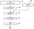
도 11 에 도시한 바와 같이, 반도체 디바이스와 같은 마이크로디바이스는, 마이크로디바이스의 기능 및 성능을 설계하는 단계 201; 이 설계 단계에 기초하여 마스크 (레티클) 를 제작하는 단계 202; 디바이스의 기재인 기판을 제조하는 단계 203; 상기 논의된 실시형태에 따라, 마스크 패턴을 이용하여 노광 광으로 기판을 노광하고 노광된 기판을 현상하는 단계를 포함하는 기판 처리 (노광 처리) 를 포함하는 기판 처리 단계 204; 디바이스 조립 단계 205 (다이싱 공정, 본딩 공정 및 패키징 공정과 같은 가공 프로세스를 포함한다); 검사 단계 206 등에 의해 제조된다.As shown in FIG. 11, a microdevice, such as a semiconductor device, includes
또한, 상기 논의된 실시형태 각각의 요건은 적절히 조합될 수 있다. 또한, 구성 요소 중 일부가 이용되지 않는 경우가 있을 수 있다. 또한, 본 출원에 의해 지정된 규정 및 법령에 의해 허용되는 정도로 상기 논의된 실시형태, 변형예 등 각각에서 이용된 노광 장치와 관련된 모든 특허 공개 및 미국 특허의 각 개시물이 본원에 참조에 의해 완전히 포함된다.In addition, the requirements of each of the embodiments discussed above may be combined as appropriate. In addition, there may be cases where some of the components are not used. In addition, each disclosure of all patent publications and US patents relating to the exposure apparatus used in each of the embodiments, modifications, and the like discussed above to the extent permitted by the regulations and statutes specified by the present application are hereby fully incorporated by reference. do.
2 : 기판 스테이지 4 : 종단 광학 소자
5 : 사출면 6 : 하면
7 : 제 1 부재 8 : 액체 회수구
9 : 제 2 부재 11 : 제 1 구동 장치
12 : 제 2 구동 장치 30 : 액체 회수면
31 : 제 1 액체 회수면 32 : 제 2 액체 회수면
33 : 제 3 액체 회수면 34 : 다공 부재
37 : 액체 공급구 EL : 노광 광
EX : 노광 장치 K : 광로
LQ : 액체 LS : 액침 공간
P : 기판2: substrate stage 4: terminal optical element
5: exit surface 6: lower surface
7: first member 8: liquid recovery port
9: second member 11: first drive device
12. Second drive device 30: Liquid recovery surface
31: first liquid recovery surface 32: second liquid recovery surface
33: third liquid recovery surface 34: porous member
37: liquid supply port EL: exposure light
EX: Exposure device K: Light path
LQ: liquid LS: immersion space
P: Substrate
Claims (27)
액체로 채워지는 광학 부재와 기판 사이의 노광 광의 광로 주위에 배치되고 제 1 방향으로 향하는 제 1 면을 갖는 제 1 부재로서, 상기 제 1 면과 물체의 표면 사이의 공간에 액체를 유지할 수 있는, 상기 제 1 부재;
상기 노광 광의 광로에 대하여 상기 제 1 면의 외측에 배치된 액체 회수구를 갖는 제 2 부재로서, 상기 액체 회수구와 상기 물체의 표면 사이의 상기 액체의 적어도 일부가 상기 액체 회수구를 통해 회수되는, 상기 제 2 부재;
적어도 상기 제 1 방향으로 상기 제 1 부재를 이동시킬 수 있는 제 1 구동 장치; 및
상기 제 1 부재와 독립적으로 적어도 상기 제 1 방향으로 상기 제 2 부재를 이동시킬 수 있는 제 2 구동 장치를 포함하는, 액침 시스템.An immersion system used for immersion exposure,
A first member disposed around an optical path of exposure light between a liquid filled optical member and a substrate and having a first surface facing in a first direction, wherein the liquid can be held in the space between the first surface and the surface of the object, The first member;
A second member having a liquid recovery port disposed outside the first surface with respect to the optical path of the exposure light, wherein at least a portion of the liquid between the liquid recovery port and the surface of the object is recovered through the liquid recovery port, The second member;
A first drive device capable of moving the first member in at least the first direction; And
And a second drive device capable of moving said second member in at least said first direction independently of said first member.
상기 물체의 이동 조건에 따라, 상기 제 1 방향에서의 상기 물체의 표면과 상기 제 1 면 사이의 위치 관계; 및 상기 제 1 방향에서의 상기 물체의 표면과 상기 액체 회수구 사이의 위치 관계 중 적어도 하나의 위치 관계가 조정되는, 액침 시스템.The method of claim 1,
A positional relationship between the surface of the object and the first surface in the first direction according to the movement condition of the object; And at least one of the positional relationship between the surface of the object and the liquid recovery port in the first direction is adjusted.
상기 물체의 이동 조건에 따라, 상기 제 1 면과 상기 액체 회수구가 상대 이동되는, 액침 시스템.The method of claim 2,
And the first surface and the liquid recovery port are relatively moved in accordance with the movement condition of the object.
상기 이동 조건은 상기 제 1 면에 실질적으로 평행인 방향으로의 상기 물체의 이동 속도를 포함하는, 액침 시스템.The method of claim 2 or 3,
And the moving condition comprises a moving speed of the object in a direction substantially parallel to the first face.
상기 이동 조건은 상기 제 1 면에 실질적으로 평행인 방향으로의 상기 물체의 직선적인 연속 이동 거리를 포함하는, 액침 시스템.The method according to any one of claims 2 to 4,
And the moving condition comprises a linear continuous moving distance of the object in a direction substantially parallel to the first face.
상기 제 1 면에 실질적으로 평행인 방향으로의 상기 물체의 이동 중에, 상기 제 1 면 및 상기 액체 회수구 중 적어도 하나가 상기 제 1 방향으로 이동되는, 액침 시스템.6. The method according to any one of claims 1 to 5,
And during movement of the object in a direction substantially parallel to the first face, at least one of the first face and the liquid recovery port is moved in the first direction.
상기 액체의 공급 조건에 따라, 상기 제 1 방향에서의 상기 물체의 표면과 상기 제 1 면 사이의 위치 관계; 및 상기 제 1 방향에서의 상기 물체의 표면과 상기 액체 회수구 사이의 위치 관계 중 적어도 하나의 위치 관계가 조정되는, 액침 시스템.The method according to any one of claims 1 to 6,
A positional relationship between the surface of the object and the first surface in the first direction according to the supply condition of the liquid; And at least one of the positional relationship between the surface of the object and the liquid recovery port in the first direction is adjusted.
상기 공급 조건은 단위 시간 당의 액체 공급량을 포함하는, 액침 시스템.The method of claim 7, wherein
And the supply condition comprises a liquid supply amount per unit time.
상기 제 1 방향에서의 상기 광학 부재의 사출면과 상기 물체의 표면 사이의 거리에 따라, 상기 제 1 방향과 평행인 방향에서의 상기 물체의 표면과 상기 제 1 면 사이의 위치 관계; 및 상기 제 1 방향에서의 상기 물체의 표면과 상기 액체 회수구 사이의 위치 관계 중 적어도 하나의 위치 관계가 조정되는, 액침 시스템.The method according to any one of claims 1 to 8,
A positional relationship between the surface of the object and the first surface in a direction parallel to the first direction, in accordance with a distance between the exit surface of the optical member in the first direction and the surface of the object; And at least one of the positional relationship between the surface of the object and the liquid recovery port in the first direction is adjusted.
상기 제 1 방향에서의 상기 광학 부재의 사출면과 상기 제 1 면 사이의 거리가 상기 제 1 방향과 평행인 방향에서의 상기 사출면과 상기 액체 회수구 사이의 거리와는 상이한, 액침 시스템.The method according to any one of claims 1 to 8,
And the distance between the exit face of the optical member and the first face in the first direction is different from the distance between the exit face and the liquid recovery port in a direction parallel to the first direction.
상기 물체의 표면과 상기 액체 회수구 사이의 거리가 상기 물체의 표면과 상기 제 1 면 사이의 거리보다 크도록 상기 제 1 방향에서의 상기 제 1 면의 위치; 및 상기 제 1 방향에서의 상기 액체 회수구의 위치 중 적어도 하나의 위치가 조정되는, 액침 시스템.The method of claim 10,
The position of the first surface in the first direction such that a distance between the surface of the object and the liquid recovery port is greater than a distance between the surface of the object and the first surface; And at least one of the position of the liquid recovery port in the first direction is adjusted.
상기 액체 회수구는 제 1 액체 회수 영역, 및 상기 노광 광의 광로에 대하여 상기 제 1 면의 외측에 배치된 제 2 액체 회수 영역을 포함하는, 액침 시스템.The method according to any one of claims 1 to 11,
And the liquid recovery port comprises a first liquid recovery region and a second liquid recovery region disposed outside of the first surface with respect to the optical path of the exposure light.
상기 제 1 액체 회수 영역 및 상기 제 2 액체 회수 영역 중 적어도 하나의 영역이 다공 부재의 표면을 포함하며,
상기 액체 회수구와 상기 물체 사이의 상기 액체의 적어도 일부가 상기 다공 부재를 통해 회수되는, 액침 시스템.The method of claim 12,
At least one of the first liquid recovery region and the second liquid recovery region comprises a surface of the porous member,
And at least a portion of the liquid between the liquid recovery port and the object is recovered through the porous member.
상기 제 1 액체 회수 영역은 상기 제 1 방향으로 향하며,
상기 제 2 액체 회수 영역의 적어도 일부는 상기 제 1 방향과 다른 방향으로 향하는, 액침 시스템.The method according to claim 12 or 13,
The first liquid recovery region faces in the first direction,
At least a portion of the second liquid recovery region faces in a direction different from the first direction.
상기 제 1 부재는 상기 광로에 상기 액체를 공급하는 액체 공급구를 가지며,
상기 액체 공급구는 상기 제 1 방향과 다른 방향으로 향하는, 액침 시스템.The method according to any one of claims 1 to 14,
The first member has a liquid supply port for supplying the liquid to the optical path,
And the liquid supply port is directed in a direction different from the first direction.
상기 제 1 부재는 상기 광로 주위에 배치되는, 액침 시스템.The method according to any one of claims 1 to 15,
And the first member is disposed around the light path.
상기 제 2 부재는 상기 광로 주위에 배치되는, 액침 시스템.The method according to any one of claims 1 to 16,
And the second member is disposed around the light path.
상기 액체 회수구는 상기 광로 주위에 배치되는, 액침 시스템.The method of claim 17,
And the liquid recovery port is disposed around the light path.
상기 물체는 상기 기판을 포함하는, 액침 시스템.The method according to any one of claims 1 to 18,
The object comprises the substrate.
액체로 채워지는 광학 부재와 기판 사이의 노광 광의 광로 주위에 배치되고 제 1 방향으로 향하는 제 1 면을 갖는 제 1 부재로서, 상기 제 1 면과 물체의 표면 사이의 공간에 액체를 유지할 수 있는, 상기 제 1 부재;
상기 노광 광의 광로에 대하여 상기 제 1 면의 외측에 배치된 액체 회수구를 갖는 제 2 부재로서, 상기 액체 회수구와 상기 물체의 표면 사이의 상기 액체의 적어도 일부가 상기 액체 회수구를 통해 회수되는, 상기 제 2 부재; 및
적어도 상기 제 1 방향으로의 제 1 부재와 제 2 부재 사이의 상대 이동을 제어할 수 있는 구동 장치를 포함하며,
상기 액체 회수구는 제 1 회수 영역, 및 상기 노광 광의 광로에 대하여 상기 제 1 면의 외측에 배치된 제 2 회수 영역을 가지며,
상기 제 1 방향에서의 상기 물체의 표면과 상기 제 1 회수 영역 사이의 거리가 상기 제 1 방향에서의 상기 물체의 표면과 상기 제 2 회수 영역 사이의 거리보다 크며,
상기 제 1 방향에서의 상기 제 1 회수 영역과 상기 제 1 면 사이의 위치 관계가 조정될 수 있는, 액침 시스템.An immersion system used for immersion exposure,
A first member disposed around an optical path of exposure light between a liquid filled optical member and a substrate and having a first surface facing in a first direction, wherein the liquid can be held in the space between the first surface and the surface of the object, The first member;
A second member having a liquid recovery port disposed outside the first surface with respect to the optical path of the exposure light, wherein at least a portion of the liquid between the liquid recovery port and the surface of the object is recovered through the liquid recovery port, The second member; And
A drive device capable of controlling relative movement between at least the first member and the second member in the first direction,
The liquid recovery port has a first recovery region and a second recovery region disposed outside the first surface with respect to the optical path of the exposure light,
The distance between the surface of the object in the first direction and the first recovery region is greater than the distance between the surface of the object in the first direction and the second recovery region,
And the positional relationship between the first recovery region and the first surface in the first direction can be adjusted.
상기 제 1 액체 회수 영역 및 상기 제 2 액체 회수 영역 중 적어도 하나의 영역이 다공 부재의 표면을 포함하며,
상기 액체 회수구와 상기 물체 사이의 상기 액체의 적어도 일부가 상기 다공 부재를 통해 회수되는, 액침 시스템.The method of claim 20,
At least one of the first liquid recovery region and the second liquid recovery region comprises a surface of the porous member,
And at least a portion of the liquid between the liquid recovery port and the object is recovered through the porous member.
상기 제 1 액체 회수 영역은 상기 제 1 방향으로 향하며,
상기 제 2 액체 회수 영역의 적어도 일부는 상기 제 1 방향과 다른 방향으로 향하는, 액침 시스템.The method of claim 20 or 21,
The first liquid recovery region faces in the first direction,
At least a portion of the second liquid recovery region faces in a direction different from the first direction.
상기 제 1 액체 회수 영역, 및 상기 제 2 액체 회수 영역의 적어도 일부는 실질적으로 평행인, 액침 시스템.The method of claim 20 or 21,
And the at least a portion of the first liquid recovery region and the second liquid recovery region are substantially parallel.
제 1 항 내지 제 23 항 중 어느 한 항에 기재된 액침 시스템을 포함하는, 노광 장치.An exposure apparatus for exposing a substrate with exposure light through a liquid,
The exposure apparatus containing the liquid immersion system in any one of Claims 1-23.
상기 노광된 기판을 현상하는 단계를 포함하는, 디바이스 제조 방법.Exposing the substrate using the exposure apparatus of claim 24; And
Developing the exposed substrate.
제 1 항 내지 제 23 항 중 어느 한 항에 기재된 액침 시스템을 이용하여, 상기 광학 부재와 상기 기판 사이의 상기 노광 광의 광로를 상기 액체로 채우는 단계; 및
상기 광학 부재 및 상기 액체를 통하여 상기 기판에 상기 노광 광을 조사하는 단계를 포함하는, 노광 방법.An exposure method for exposing a substrate with exposure light through a liquid,
Using the liquid immersion system according to any one of claims 1 to 23, filling an optical path of the exposure light between the optical member and the substrate with the liquid; And
Irradiating the exposure light to the substrate through the optical member and the liquid.
상기 노광된 기판을 현상하는 단계를 포함하는, 디바이스 제조 방법.Exposing the substrate using the exposure method of claim 26; And
Developing the exposed substrate.
Applications Claiming Priority (4)
| Application Number | Priority Date | Filing Date | Title |
|---|---|---|---|
| US6481008P | 2008-03-27 | 2008-03-27 | |
| US61/064,810 | 2008-03-27 | ||
| US12/382,742 | 2009-03-23 | ||
| US12/382,742 US8233139B2 (en) | 2008-03-27 | 2009-03-23 | Immersion system, exposure apparatus, exposing method, and device fabricating method |
Publications (1)
| Publication Number | Publication Date |
|---|---|
| KR20100133446A true KR20100133446A (en) | 2010-12-21 |
Family
ID=40793250
Family Applications (1)
| Application Number | Title | Priority Date | Filing Date |
|---|---|---|---|
| KR1020107023702A KR20100133446A (en) | 2008-03-27 | 2009-03-26 | Immersion system, exposure apparatus, exposing method and device fabricating method |
Country Status (5)
| Country | Link |
|---|---|
| US (2) | US8233139B2 (en) |
| JP (1) | JP2009239286A (en) |
| KR (1) | KR20100133446A (en) |
| TW (1) | TW200947145A (en) |
| WO (1) | WO2009119898A1 (en) |
Families Citing this family (10)
| Publication number | Priority date | Publication date | Assignee | Title |
|---|---|---|---|---|
| US8477283B2 (en) * | 2006-05-10 | 2013-07-02 | Nikon Corporation | Exposure apparatus and device manufacturing method |
| US8233139B2 (en) * | 2008-03-27 | 2012-07-31 | Nikon Corporation | Immersion system, exposure apparatus, exposing method, and device fabricating method |
| US8896806B2 (en) | 2008-12-29 | 2014-11-25 | Nikon Corporation | Exposure apparatus, exposure method, and device manufacturing method |
| WO2011083724A1 (en) * | 2010-01-08 | 2011-07-14 | 株式会社ニコン | Liquid-immersion member, exposing device, exposing method, and device manufacturing method |
| NL2009692A (en) * | 2011-12-07 | 2013-06-10 | Asml Netherlands Bv | A lithographic apparatus and a device manufacturing method. |
| US9323160B2 (en) * | 2012-04-10 | 2016-04-26 | Nikon Corporation | Liquid immersion member, exposure apparatus, exposure method, device fabricating method, program, and recording medium |
| US9823580B2 (en) * | 2012-07-20 | 2017-11-21 | Nikon Corporation | Liquid immersion member, exposure apparatus, exposing method, method for manufacturing device, program, and recording medium |
| US9494870B2 (en) * | 2012-10-12 | 2016-11-15 | Nikon Corporation | Exposure apparatus, exposing method, device manufacturing method, program, and recording medium |
| US9720331B2 (en) * | 2012-12-27 | 2017-08-01 | Nikon Corporation | Liquid immersion member, exposure apparatus, exposing method, method of manufacturing device, program, and recording medium |
| NL2014915A (en) | 2014-07-01 | 2016-03-31 | Asml Netherlands Bv | A Lithographic Apparatus and a Method of Manufacturing a Lithographic Apparatus. |
Family Cites Families (32)
| Publication number | Priority date | Publication date | Assignee | Title |
|---|---|---|---|---|
| CN1244021C (en) | 1996-11-28 | 2006-03-01 | 株式会社尼康 | Photoetching device and exposure method |
| USRE40043E1 (en) | 1997-03-10 | 2008-02-05 | Asml Netherlands B.V. | Positioning device having two object holders |
| US6897963B1 (en) | 1997-12-18 | 2005-05-24 | Nikon Corporation | Stage device and exposure apparatus |
| US6208407B1 (en) | 1997-12-22 | 2001-03-27 | Asm Lithography B.V. | Method and apparatus for repetitively projecting a mask pattern on a substrate, using a time-saving height measurement |
| AU1262499A (en) | 1998-03-11 | 1999-09-27 | Nikon Corporation | Ultraviolet laser apparatus and exposure apparatus comprising the ultraviolet laser apparatus |
| WO2001035168A1 (en) | 1999-11-10 | 2001-05-17 | Massachusetts Institute Of Technology | Interference lithography utilizing phase-locked scanning beams |
| WO2002069049A2 (en) | 2001-02-27 | 2002-09-06 | Asml Us, Inc. | Simultaneous imaging of two reticles |
| TW529172B (en) | 2001-07-24 | 2003-04-21 | Asml Netherlands Bv | Imaging apparatus |
| JP2005536775A (en) | 2002-08-23 | 2005-12-02 | 株式会社ニコン | Projection optical system, photolithography method and exposure apparatus, and method using exposure apparatus |
| EP3352015A1 (en) | 2003-04-10 | 2018-07-25 | Nikon Corporation | Environmental system including a transport region for an immersion lithography apparatus |
| EP2270599A1 (en) | 2003-05-13 | 2011-01-05 | ASML Netherlands BV | Lithographic apparatus |
| TWI295414B (en) * | 2003-05-13 | 2008-04-01 | Asml Netherlands Bv | Lithographic apparatus and device manufacturing method |
| KR101238114B1 (en) | 2003-09-03 | 2013-02-27 | 가부시키가이샤 니콘 | Apparatus and method for providing fluid for immersion lithography |
| JP4378136B2 (en) | 2003-09-04 | 2009-12-02 | キヤノン株式会社 | Exposure apparatus and device manufacturing method |
| KR101441777B1 (en) * | 2004-03-25 | 2014-09-22 | 가부시키가이샤 니콘 | Exposure apparatus and method for manufacturing device |
| EP1768169B9 (en) | 2004-06-04 | 2013-03-06 | Nikon Corporation | Exposure apparatus, exposure method, and device producing method |
| JP4543767B2 (en) | 2004-06-10 | 2010-09-15 | 株式会社ニコン | Exposure apparatus and device manufacturing method |
| US7701550B2 (en) | 2004-08-19 | 2010-04-20 | Asml Netherlands B.V. | Lithographic apparatus and device manufacturing method |
| US8675174B2 (en) | 2004-09-17 | 2014-03-18 | Nikon Corporation | Exposure apparatus, exposure method, and method for producing device |
| US7161654B2 (en) * | 2004-12-02 | 2007-01-09 | Asml Netherlands B.V. | Lithographic apparatus and device manufacturing method |
| JP5005226B2 (en) * | 2005-01-31 | 2012-08-22 | 株式会社ニコン | Exposure apparatus, device manufacturing method, and liquid holding method |
| US7411654B2 (en) | 2005-04-05 | 2008-08-12 | Asml Netherlands B.V. | Lithographic apparatus and device manufacturing method |
| JP4802604B2 (en) * | 2005-08-17 | 2011-10-26 | 株式会社ニコン | Exposure apparatus, exposure method, and device manufacturing method |
| US7751026B2 (en) | 2005-08-25 | 2010-07-06 | Nikon Corporation | Apparatus and method for recovering fluid for immersion lithography |
| US7864292B2 (en) * | 2005-11-16 | 2011-01-04 | Asml Netherlands B.V. | Lithographic apparatus and device manufacturing method |
| US7804577B2 (en) | 2005-11-16 | 2010-09-28 | Asml Netherlands B.V. | Lithographic apparatus |
| US8477283B2 (en) | 2006-05-10 | 2013-07-02 | Nikon Corporation | Exposure apparatus and device manufacturing method |
| JP2007335662A (en) * | 2006-06-15 | 2007-12-27 | Canon Inc | Exposure apparatus |
| JP2008034801A (en) * | 2006-06-30 | 2008-02-14 | Canon Inc | Exposure apparatus and device manufacturing method |
| US8134685B2 (en) | 2007-03-23 | 2012-03-13 | Nikon Corporation | Liquid recovery system, immersion exposure apparatus, immersion exposing method, and device fabricating method |
| US20090122282A1 (en) | 2007-05-21 | 2009-05-14 | Nikon Corporation | Exposure apparatus, liquid immersion system, exposing method, and device fabricating method |
| US8233139B2 (en) * | 2008-03-27 | 2012-07-31 | Nikon Corporation | Immersion system, exposure apparatus, exposing method, and device fabricating method |
-
2009
- 2009-03-23 US US12/382,742 patent/US8233139B2/en active Active
- 2009-03-25 JP JP2009074674A patent/JP2009239286A/en active Pending
- 2009-03-26 TW TW098109833A patent/TW200947145A/en unknown
- 2009-03-26 WO PCT/JP2009/056843 patent/WO2009119898A1/en active Application Filing
- 2009-03-26 KR KR1020107023702A patent/KR20100133446A/en not_active Application Discontinuation
-
2012
- 2012-06-20 US US13/528,379 patent/US20120300181A1/en not_active Abandoned
Also Published As
| Publication number | Publication date |
|---|---|
| WO2009119898A1 (en) | 2009-10-01 |
| TW200947145A (en) | 2009-11-16 |
| US20090280436A1 (en) | 2009-11-12 |
| US20120300181A1 (en) | 2012-11-29 |
| JP2009239286A (en) | 2009-10-15 |
| US8233139B2 (en) | 2012-07-31 |
Similar Documents
| Publication | Publication Date | Title |
|---|---|---|
| US8233139B2 (en) | Immersion system, exposure apparatus, exposing method, and device fabricating method | |
| JP4802604B2 (en) | Exposure apparatus, exposure method, and device manufacturing method | |
| TWI698720B (en) | Liquid immersion member, exposure apparatus, exposure method, device fabricating method, program, and recording medium | |
| US10310383B2 (en) | Exposure apparatus, exposure method, and device manufacturing method | |
| US8953143B2 (en) | Liquid immersion member | |
| US20100304310A1 (en) | Exposure apparatus, exposure method, and device manufacturing method | |
| KR20090126239A (en) | Liquid recovery system, immersion exposure apparatus, immersion exposing method, and device fabricating method | |
| JPWO2007132862A1 (en) | Projection optical system, exposure method, exposure apparatus, and device manufacturing method | |
| JP2010528449A (en) | Exposure apparatus, immersion system, exposure method, and device manufacturing method | |
| US20090218743A1 (en) | Substrate holding apparatus, exposure apparatus, exposing method, device fabricating method, plate member, and wall | |
| JP2010205914A (en) | Exposure device, exposure method, and method for manufacturing device | |
| US8379189B2 (en) | Stage device, exposure apparatus, exposure method and device manufacturing method | |
| US20100328637A1 (en) | Exposure apparatus, exposing method and device fabricating method | |
| US20100196832A1 (en) | Exposure apparatus, exposing method, liquid immersion member and device fabricating method | |
| US20100323303A1 (en) | Liquid immersion member, exposure apparatus, exposing method, and device fabricating method | |
| JP5375843B2 (en) | Exposure apparatus, exposure method, and device manufacturing method | |
| JP2010135794A (en) | Immersion lithography apparatus and method, and device manufacturing method | |
| JP2011222652A (en) | Substrate stage, exposure equipment and immersion exposure method using the same, and device manufacturing method using the method | |
| JP2007035934A (en) | Exposure device and method of manufacturing device | |
| JP2010135796A (en) | Immersion lithography apparatus and method, and device manufacturing method | |
| JP2010157724A (en) | Exposure apparatus, exposure method, and device manufacturing method | |
| JP5407383B2 (en) | Exposure apparatus and device manufacturing method | |
| JP2010034227A (en) | Stage device, exposure device, exposure method, and device manufacturing method | |
| JP2008021718A (en) | Photolithography machine, and manufacturing method of device | |
| JP2009212234A (en) | Liquid collecting system, exposure apparatus, exposure method, and device manufacturing method |
Legal Events
| Date | Code | Title | Description |
|---|---|---|---|
| WITN | Application deemed withdrawn, e.g. because no request for examination was filed or no examination fee was paid |