KR20100031694A - Exposure apparatus, device manufacturing method, cleaning device, cleaning method and exposure method - Google Patents
Exposure apparatus, device manufacturing method, cleaning device, cleaning method and exposure method Download PDFInfo
- Publication number
- KR20100031694A KR20100031694A KR1020097027052A KR20097027052A KR20100031694A KR 20100031694 A KR20100031694 A KR 20100031694A KR 1020097027052 A KR1020097027052 A KR 1020097027052A KR 20097027052 A KR20097027052 A KR 20097027052A KR 20100031694 A KR20100031694 A KR 20100031694A
- Authority
- KR
- South Korea
- Prior art keywords
- liquid
- exposure
- cleaning
- substrate
- vibration
- Prior art date
Links
Images


Classifications
-
- G—PHYSICS
- G03—PHOTOGRAPHY; CINEMATOGRAPHY; ANALOGOUS TECHNIQUES USING WAVES OTHER THAN OPTICAL WAVES; ELECTROGRAPHY; HOLOGRAPHY
- G03F—PHOTOMECHANICAL PRODUCTION OF TEXTURED OR PATTERNED SURFACES, e.g. FOR PRINTING, FOR PROCESSING OF SEMICONDUCTOR DEVICES; MATERIALS THEREFOR; ORIGINALS THEREFOR; APPARATUS SPECIALLY ADAPTED THEREFOR
- G03F7/00—Photomechanical, e.g. photolithographic, production of textured or patterned surfaces, e.g. printing surfaces; Materials therefor, e.g. comprising photoresists; Apparatus specially adapted therefor
- G03F7/70—Microphotolithographic exposure; Apparatus therefor
- G03F7/70216—Mask projection systems
- G03F7/70341—Details of immersion lithography aspects, e.g. exposure media or control of immersion liquid supply
-
- G—PHYSICS
- G03—PHOTOGRAPHY; CINEMATOGRAPHY; ANALOGOUS TECHNIQUES USING WAVES OTHER THAN OPTICAL WAVES; ELECTROGRAPHY; HOLOGRAPHY
- G03F—PHOTOMECHANICAL PRODUCTION OF TEXTURED OR PATTERNED SURFACES, e.g. FOR PRINTING, FOR PROCESSING OF SEMICONDUCTOR DEVICES; MATERIALS THEREFOR; ORIGINALS THEREFOR; APPARATUS SPECIALLY ADAPTED THEREFOR
- G03F7/00—Photomechanical, e.g. photolithographic, production of textured or patterned surfaces, e.g. printing surfaces; Materials therefor, e.g. comprising photoresists; Apparatus specially adapted therefor
- G03F7/70—Microphotolithographic exposure; Apparatus therefor
- G03F7/708—Construction of apparatus, e.g. environment aspects, hygiene aspects or materials
- G03F7/70908—Hygiene, e.g. preventing apparatus pollution, mitigating effect of pollution or removing pollutants from apparatus
- G03F7/70925—Cleaning, i.e. actively freeing apparatus from pollutants, e.g. using plasma cleaning
-
- G—PHYSICS
- G03—PHOTOGRAPHY; CINEMATOGRAPHY; ANALOGOUS TECHNIQUES USING WAVES OTHER THAN OPTICAL WAVES; ELECTROGRAPHY; HOLOGRAPHY
- G03F—PHOTOMECHANICAL PRODUCTION OF TEXTURED OR PATTERNED SURFACES, e.g. FOR PRINTING, FOR PROCESSING OF SEMICONDUCTOR DEVICES; MATERIALS THEREFOR; ORIGINALS THEREFOR; APPARATUS SPECIALLY ADAPTED THEREFOR
- G03F7/00—Photomechanical, e.g. photolithographic, production of textured or patterned surfaces, e.g. printing surfaces; Materials therefor, e.g. comprising photoresists; Apparatus specially adapted therefor
- G03F7/20—Exposure; Apparatus therefor
- G03F7/2041—Exposure; Apparatus therefor in the presence of a fluid, e.g. immersion; using fluid cooling means
-
- G—PHYSICS
- G03—PHOTOGRAPHY; CINEMATOGRAPHY; ANALOGOUS TECHNIQUES USING WAVES OTHER THAN OPTICAL WAVES; ELECTROGRAPHY; HOLOGRAPHY
- G03F—PHOTOMECHANICAL PRODUCTION OF TEXTURED OR PATTERNED SURFACES, e.g. FOR PRINTING, FOR PROCESSING OF SEMICONDUCTOR DEVICES; MATERIALS THEREFOR; ORIGINALS THEREFOR; APPARATUS SPECIALLY ADAPTED THEREFOR
- G03F7/00—Photomechanical, e.g. photolithographic, production of textured or patterned surfaces, e.g. printing surfaces; Materials therefor, e.g. comprising photoresists; Apparatus specially adapted therefor
- G03F7/70—Microphotolithographic exposure; Apparatus therefor
- G03F7/70691—Handling of masks or workpieces
- G03F7/70716—Stages
-
- G—PHYSICS
- G03—PHOTOGRAPHY; CINEMATOGRAPHY; ANALOGOUS TECHNIQUES USING WAVES OTHER THAN OPTICAL WAVES; ELECTROGRAPHY; HOLOGRAPHY
- G03F—PHOTOMECHANICAL PRODUCTION OF TEXTURED OR PATTERNED SURFACES, e.g. FOR PRINTING, FOR PROCESSING OF SEMICONDUCTOR DEVICES; MATERIALS THEREFOR; ORIGINALS THEREFOR; APPARATUS SPECIALLY ADAPTED THEREFOR
- G03F7/00—Photomechanical, e.g. photolithographic, production of textured or patterned surfaces, e.g. printing surfaces; Materials therefor, e.g. comprising photoresists; Apparatus specially adapted therefor
- G03F7/70—Microphotolithographic exposure; Apparatus therefor
- G03F7/708—Construction of apparatus, e.g. environment aspects, hygiene aspects or materials
- G03F7/70908—Hygiene, e.g. preventing apparatus pollution, mitigating effect of pollution or removing pollutants from apparatus
- G03F7/70933—Purge, e.g. exchanging fluid or gas to remove pollutants
Landscapes
- Physics & Mathematics (AREA)
- General Physics & Mathematics (AREA)
- Health & Medical Sciences (AREA)
- Epidemiology (AREA)
- Public Health (AREA)
- Engineering & Computer Science (AREA)
- Life Sciences & Earth Sciences (AREA)
- Atmospheric Sciences (AREA)
- Environmental & Geological Engineering (AREA)
- Plasma & Fusion (AREA)
- Exposure And Positioning Against Photoresist Photosensitive Materials (AREA)
- Exposure Of Semiconductors, Excluding Electron Or Ion Beam Exposure (AREA)
Abstract
Description
기술분야Field of technology
본 발명은, 기판을 노광하는 노광 장치, 디바이스 제조 방법, 세정 장치, 및 노광 장치의 클리닝 방법 그리고 노광 방법에 관한 것이다.The present invention relates to an exposure apparatus for exposing a substrate, a device manufacturing method, a cleaning apparatus, a cleaning method for an exposure apparatus, and an exposure method.
배경기술Background
포토리소그래피 공정에서 사용되는 노광 장치에 있어서, 하기 특허 문헌에 개시되어 있는, 액체를 통하여 노광광으로 기판을 노광하는 액침 노광 장치가 알려져 있다.In the exposure apparatus used in a photolithography process, the immersion exposure apparatus which exposes a board | substrate with exposure light through the liquid disclosed by the following patent document is known.
특허 문헌 1 : 국제 공개 제99/49504호 팜플렛Patent Document 1: International Publication No. 99/49504 Pamphlet
특허 문헌 2 : 일본 공개특허공보 2004-289127호Patent Document 2: Japanese Unexamined Patent Publication No. 2004-289127
발명의 개시Disclosure of Invention
발명이 해결하고자 하는 과제Problems to be Solved by the Invention
액침 노광 장치에 있어서, 액침 공간의 액체와 접촉하는 부재가 오염될 가능성이 있다. 그 부재가 오염된 상태를 방치해 두면, 노광 장치의 성능이 열화되어, 기판을 양호하게 노광할 수 없게 될 가능성이 있다.In the liquid immersion exposure apparatus, there is a possibility that the member in contact with the liquid in the liquid immersion space is contaminated. If the member is left in a contaminated state, the performance of the exposure apparatus may deteriorate, and the substrate may not be exposed well.
본 발명은, 오염에서 기인되는 성능의 열화를 억제할 수 있는 노광 장치, 및 그 노광 장치를 사용하는 디바이스 제조 방법을 제공하는 것을 목적으로 한다. 또 본 발명은, 액침 노광 장치를 양호하게 클리닝할 수 있는 세정 장치, 및 그 세정 장치를 사용하는 클리닝 방법 그리고 노광 방법을 제공하는 것을 목적으로 한다.An object of the present invention is to provide an exposure apparatus capable of suppressing deterioration in performance resulting from contamination, and a device manufacturing method using the exposure apparatus. Moreover, an object of this invention is to provide the washing | cleaning apparatus which can favorably clean a liquid immersion exposure apparatus, the cleaning method using the washing apparatus, and an exposure method.
과제를 해결하기 위한 수단Means to solve the problem
본 발명의 제 1 양태에 따르면, 노광용 액체를 통하여 노광광으로 기판을 노광하는 노광 장치로서, 노광광을 사출하는 광학 소자와, 광학 소자의 사출측에서 이동할 수 있는 가동 부재와, 가동 부재에 탑재된 소정 부재와, 소정 부재를 진동시킴으로써 소정 부재 상의 클리닝용 액체에 진동을 부여하는 진동 발생 장치를 구비하고, 상기 소정 부재의 표면의 적어도 일부는, 상기 노광용 액체와 상기 클리닝용 액체의 적어도 일방에 대해 발액성인 노광 장치가 제공된다.According to a first aspect of the present invention, there is provided an exposure apparatus for exposing a substrate with exposure light through an exposure liquid, comprising: an optical element for emitting exposure light, a movable member that can move from the exit side of the optical element, and a movable member And a vibration generating device that imparts vibration to the cleaning liquid on the predetermined member by vibrating the predetermined member, and at least a part of the surface of the predetermined member is disposed at least one of the exposure liquid and the cleaning liquid. An exposure apparatus which is liquid-repellent for a liquid is provided.
본 발명의 제 2 양태에 따르면, 노광용 액체를 통하여 노광광으로 기판을 노광하는 노광 장치로서, 노광광을 사출하는 광학 소자와, 광학 소자의 사출측에서 이동할 수 있는 가동 부재와, 가동 부재에 탑재된 소정 부재와, 소정 부재를 진동시킴으로써 소정 부재 상의 클리닝용 액체에 진동을 부여하는 진동 발생 장치와, 진동 발생 장치가 발생하는 열의 발산을 억제하는 억제 장치를 구비한 노광 장치가 제공된다.According to a second aspect of the present invention, there is provided an exposure apparatus for exposing a substrate with exposure light through an exposure liquid, comprising: an optical element for emitting exposure light, a movable member that can move from the exit side of the optical element, and a movable member; The exposure apparatus provided with the predetermined member, the vibration generating apparatus which gives a vibration to the cleaning liquid on a predetermined member by vibrating a predetermined member, and the suppression apparatus which suppresses the dissipation of the heat which a vibration generating apparatus produces.
본 발명의 제 3 양태에 따르면, 상기 양태의 노광 장치를 사용하여 기판을 노광하는 것과, 노광된 기판을 현상하는 것을 포함하는 디바이스 제조 방법이 제공된다.According to a third aspect of the present invention, there is provided a device manufacturing method comprising exposing a substrate using the exposure apparatus of the above aspect and developing the exposed substrate.
본 발명의 제 4 양태에 따르면, 노광용 액체를 통하여 노광광으로 기판을 노광하는 액침 노광 장치에 사용되는 세정 장치로서, 소정 부재와, 소정 부재를 진동시킴으로써 소정 부재에 접촉하는 클리닝용 액체에 진동을 부여하는 진동 발생 장치를 구비하고, 소정 부재의 표면의 적어도 일부는, 노광용 액체와 클리닝용 액체의 적어도 일방에 대해 발액성인 세정 장치가 제공된다.According to a fourth aspect of the present invention, there is provided a cleaning apparatus used for an immersion exposure apparatus that exposes a substrate with exposure light through an exposure liquid, wherein the predetermined member and the cleaning liquid contacting the predetermined member by vibrating the predetermined member are subjected to vibration. It is provided with the vibration generating apparatus provided, and the washing | cleaning apparatus which is liquid-repellent with respect to at least one of the exposure liquid and the cleaning liquid is provided at least one part of the surface of a predetermined member.
본 발명의 제 5 양태에 따르면, 노광용 액체를 통하여 노광광으로 기판을 노광하는 액침 노광 장치에 사용되는 세정 장치로서, 소정 부재와, 소정 부재를 진동시킴으로써 소정 부재에 접촉하는 클리닝용 액체에 진동을 부여하는 진동 발생 장치와, 진동 발생 장치가 발생하는 열의 발산을 억제하는 억제 장치를 구비한 세정 장치가 제공된다.According to a fifth aspect of the present invention, there is provided a cleaning apparatus used for an immersion exposure apparatus that exposes a substrate with exposure light through an exposure liquid, wherein the predetermined member and the cleaning liquid contacting the predetermined member by vibrating the predetermined member are subjected to vibration. There is provided a cleaning device including a vibration generating device to be applied and a suppressing device for suppressing the dissipation of heat generated by the vibration generating device.
본 발명의 제 6 양태에 따르면, 노광용 액체를 통하여 노광광으로 기판을 노광하는 액침 노광 장치에 있어서, 상기 양태의 세정 장치의 소정 부재 상에 클리닝용 액체로 액침 공간을 형성하는 것과, 액침 공간의 클리닝용 액체에 초음파 진동을 부여하는 것을 포함하는 클리닝 방법이 제공된다.According to a sixth aspect of the present invention, in a liquid immersion exposure apparatus for exposing a substrate with exposure light through an exposure liquid, forming a liquid immersion space with a cleaning liquid on a predetermined member of the cleaning apparatus of the above aspect; There is provided a cleaning method comprising imparting ultrasonic vibrations to a cleaning liquid.
본 발명의 제 7 양태에 따르면, 제 1 및 제 2 테이블을 갖는 노광 장치를 사용하여 노광광으로 노광 액체를 통하여 기판을 노광하는 액침 노광 방법으로서, 광학 소자와, 상기 제 1 테이블에 설치된 계측기 사이에 놓여진 노광 액체를 통하여 노광 조건을 결정하기 위한 계측을 실행하는 것과 ; 기판과 상기 광학 소자 사이에 유지하면서 노광광으로 노광 액체를 통하여 기판을 노광하는 것과 ; 상기 제 1 테이블 또는 상기 제 2 테이블에 설치된 진동자와 상기 광학 소자 사이에 클리닝 액 체를 두고, 상기 진동자를 진동시킴으로써 상기 노광 장치의 노광 액체와 접하는 부위를 세정하는 것을 포함하는 액침 노광 방법이 제공된다.According to a seventh aspect of the present invention, a liquid immersion exposure method for exposing a substrate through an exposure liquid with exposure light using an exposure apparatus having first and second tables, comprising: between an optical element and a measuring instrument provided in the first table Performing measurement for determining exposure conditions via the exposure liquid placed on the substrate; Exposing the substrate through an exposure liquid with exposure light while holding between the substrate and the optical element; There is provided a liquid immersion exposure method comprising placing a cleaning liquid between the vibrator provided on the first table or the second table and the optical element and vibrating the vibrator to clean a portion in contact with the exposure liquid of the exposure apparatus. .
발명의 효과Effects of the Invention
상기 본 발명의 각 양태에 의하면, 오염에서 기인되는 노광 장치의 성능의 열화를 억제할 수 있다.According to each aspect of the present invention, it is possible to suppress deterioration of the performance of the exposure apparatus caused by contamination.
도면의 간단한 설명Brief description of the drawings
도 1 은 제 1 실시형태에 관련된 노광 장치를 도시한 개략 구성도이다.1 is a schematic configuration diagram showing an exposure apparatus according to a first embodiment.
도 2 는 제 1 실시형태에 관련된 기판 테이블 및 노즐 부재의 근방을 도시한 측단면도이다.FIG. 2 is a side sectional view showing the vicinity of the substrate table and the nozzle member according to the first embodiment. FIG.
도 3 은 제 1 실시형태에 관련된 기판 테이블을 도시한 사시도이다.3 is a perspective view illustrating a substrate table according to the first embodiment.
도 4 는 제 1 실시형태에 관련된 클리닝 동작의 일례를 설명하기 위한 도면이다.4 is a diagram for explaining an example of a cleaning operation according to the first embodiment.
도 5 는 제 2 실시형태에 관련된 기판 테이블 및 노즐 부재의 근방을 도시한 측단면도이다.FIG. 5 is a side sectional view showing the vicinity of the substrate table and the nozzle member according to the second embodiment. FIG.
도 6 은 제 2 실시형태에 관련된 기판 테이블을 도시한 사시도이다.6 is a perspective view illustrating a substrate table according to a second embodiment.
도 7 은 제 3 실시형태에 관련된 계측 테이블을 도시한 사시도이다.7 is a perspective view illustrating a measurement table according to a third embodiment.
도 8 은 제 4 실시형태에 관련된 억제 장치의 일례를 도시한 측단면도이다.8 is a side sectional view showing an example of a suppression device according to a fourth embodiment.
도 9 는 제 4 실시형태에 관련된 억제 장치의 일례를 도시한 측단면도이다.9 is a side sectional view showing an example of a suppression device according to a fourth embodiment.
도 10 은 제 4 실시형태에 관련된 억제 장치의 일례를 도시한 측단면도이다.FIG. 10 is a side sectional view showing an example of the suppressing device according to the fourth embodiment. FIG.
도 11 은 제 4 실시형태에 관련된 억제 장치의 일례를 도시한 측단면도이다.FIG. 11 is a side sectional view showing an example of the suppressing device according to the fourth embodiment. FIG.
도 12 는 제 4 실시형태에 관련된 억제 장치의 일례를 도시한 측단면도이다.12 is a side sectional view showing an example of the suppressing device according to the fourth embodiment.
도 13 은 제 4 실시형태에 관련된 억제 장치의 일례를 도시한 측단면도이다.It is a side sectional view which shows an example of the suppression apparatus which concerns on 4th Embodiment.
도 14 는 클리닝 동작을 포함하는 액침 노광 시퀀스의 일례를 설명하는 플로우 차트이다.14 is a flowchart for explaining an example of a liquid immersion exposure sequence including a cleaning operation.
도 15 는 마이크로 디바이스의 제조 공정의 일례를 도시한 플로우 차트도이다.15 is a flowchart illustrating an example of a manufacturing process of a micro device.
발명을 실시하기 위한 최선의 형태Best Mode for Carrying Out the Invention
이하, 본 발명의 노광 장치, 및 거기에 사용하는 세정 장치에 관한 실시형태에 대해 도면을 참조하면서 설명하지만, 본 발명은 이것에 한정되지 않는다. 또한, 이하의 설명에서는, XYZ 직교 좌표계를 설정하고, 이 XYZ 직교 좌표계를 참조하면서 노광 장치, 및 거기에 사용하는 세정 장치의 각 부재의 위치 관계에 대해 설명한다. 수평면 내의 소정 방향을 X 축 방향, 수평면 내에 있어서 X 축 방향과 직교하는 방향을 Y 축 방향, X 축 방향 및 Y 축 방향의 각각에 직교하는 방향 (즉, 연직 방향) 을 Z 축 방향으로 한다. 또한, X 축, Y 축, 및 Z 축 둘레의 회전 (경사) 방향을 각각, θX, θY 및 θZ 방향으로 한다.EMBODIMENT OF THE INVENTION Hereinafter, although embodiment which concerns on the exposure apparatus of this invention and the washing | cleaning apparatus used therein is demonstrated referring drawings, this invention is not limited to this. In addition, in the following description, the positional relationship of each member of an exposure apparatus and the washing | cleaning apparatus used for it is demonstrated, setting an XYZ rectangular coordinate system and referring this XYZ rectangular coordinate system. A direction orthogonal to the X axis direction in the horizontal plane in the X-axis direction, and a direction orthogonal to each of the Y axis direction, the X axis direction and the Y axis direction (ie, the vertical direction) in the horizontal plane is the Z axis direction. In addition, the rotation (tilt) directions around the X axis, the Y axis, and the Z axis are respectively θX, θY, and θZ directions.
<제 1 실시형태><1st embodiment>
제 1 실시형태에 대해 설명한다. 도 1 은 제 1 실시형태에 관련된 노광 장치 (EX) 를 도시한 개략 구성도이다. 본 실시형태에서는, 노광 장치 (EX) 가, 예를 들어 미국 특허 공보 제6,897,963호, 유럽 특허 출원 공개 공보 제1,713,113호 등에 개시되어 있는 기판 (P) 을 유지하여 이동할 수 있는 기판 스테 이지 (2) 와, 기판 (P) 을 유지하지 않고, 노광에 관한 소정 계측을 실행할 수 있는 계측기를 탑재하여 이동할 수 있는 계측 스테이지 (3) 를 구비한 노광 장치인 경우를 예로 들어 설명한다.The first embodiment will be described. FIG. 1: is a schematic block diagram which shows the exposure apparatus EX which concerns on 1st Embodiment. In the present embodiment, the
도 1 에 있어서, 노광 장치 (EX) 는, 마스크 (M) 를 유지하여 이동할 수 있는 마스크 스테이지 (1) 와, 기판 (P) 을 유지하여 이동할 수 있는 기판 스테이지 (2) 와, 기판 (P) 을 유지하지 않고, 노광에 관한 소정 계측을 실행할 수 있는 계측기를 탑재하고, 기판 스테이지 (2) 와는 독립하여 이동할 수 있는 계측 스테이지 (3) 와, 마스크 스테이지 (1) 를 이동하는 제 1 구동 시스템 (4) 과, 기판 스테이지 (2) 및 계측 스테이지 (3) 를 이동하는 제 2 구동 시스템 (5) 과, 각 스테이지의 위치 정보를 계측하는 레이저 간섭계 (6A, 6B) 를 포함하는 간섭계 시스템 (6) 과, 마스크 (M) 를 노광광 (EL) 으로 조명하는 조명계 (IL) 와, 노광광 (EL) 으로 조명된 마스크 (M) 패턴의 이미지를 기판 (P) 에 투영하는 투영 광학계 (PL) 와, 노광 장치 (EX) 전체의 동작을 제어하는 제어 장치 (7) 를 구비하고 있다.1, the exposure apparatus EX is the
또한, 여기서 말하는 기판 (P) 은, 디바이스를 제조하기 위한 노광용 기판으로서, 실리콘 웨이퍼와 같은 반도체 웨이퍼 등의 기재 (基材) 에 감광재 (포토레지스트) 막을 형성한 것을 포함하고, 감광재에 추가로 보호막 (탑코트 막) 등의 각종 막을 도포한 것을 포함한다. 마스크 (M) 는, 기판 (P) 에 투영되는 디바이스 패턴이 형성된 레티클을 포함한다. 본 실시형태에서는, 마스크로서 투과형 마스크를 사용하지만, 반사형 마스크를 사용할 수도 있다. 투과형 마스크는, 차광막으로 패턴이 형성되는 바이너리 마스크에 한정되지 않고, 예를 들어 하프톤형, 혹은 공간 주파수 변조형 등의 위상 시프트 마스크도 포함한다.In addition, the board | substrate P here is an exposure board | substrate for manufacturing a device, including what provided the photosensitive material (photoresist) film | membrane in the base materials, such as a semiconductor wafer, such as a silicon wafer, and adds to the photosensitive material And a coating of various films such as a protective film (top coat film). The mask M includes the reticle in which the device pattern projected on the board | substrate P was formed. In this embodiment, although a transmissive mask is used as a mask, a reflective mask can also be used. The transmissive mask is not limited to the binary mask in which the pattern is formed by the light shielding film, and also includes a phase shift mask such as a halftone type or a spatial frequency modulation type.
본 실시형태의 노광 장치 (EX) 는, 노광용 액체 (LQ) 를 통하여 노광광 (EL) 으로 기판 (P) 을 노광하는 액침 노광 장치로서, 노광광 (EL) 의 광로 공간의 적어도 일부가 노광용 액체 (LQ) 로 채워지도록, 노광용 액체 (LQ) 로 제 1 액침 공간 (LS1) 을 형성한다. 본 실시형태에서는, 투영 광학계 (PL) 의 복수의 광학 소자 중, 투영 광학계 (PL) 의 이미지면에 가장 가까운 종단 광학 소자 (11) 와, 그 종단 광학 소자 (11) 와 대향하는 물체 사이의 노광광 (EL) 의 광로 공간이 노광용 액체 (LQ) 로 채워지도록 제 1 액침 공간 (LS1) 이 형성된다. 본 명세서에서는,「액침 공간」을 실제로 액체로 채워져 있는 공간 또는 영역을 액침 공간으로 부르고 있다. 종단 광학 소자 (11) 는, 투영 광학계 (PL) 의 이미지면을 향하여 노광광 (EL) 을 사출하는 하면 (사출면, 11A) 을 갖고, 제 1 액침 공간 (LS1) 은, 종단 광학 소자 (11) 의 하면 (11A) 과, 그 종단 광학 소자 (11) 의 사출면 (11A) 과 대향하는 물체 사이의 노광광 (EL) 의 광로 공간을 노광용 액체 (LQ) 로 채우도록 형성된다. 노광 장치 (EX) 는, 노광용 액체 (LQ) 를 통하여 기판 (P) 에 노광광 (EL) 을 조사하여 그 기판 (P) 을 노광한다.The exposure apparatus EX of the present embodiment is a liquid immersion exposure apparatus that exposes the substrate P with the exposure light EL through the exposure liquid LQ, and at least a part of the optical path space of the exposure light EL is the exposure liquid. The first liquid immersion space LS1 is formed of the exposure liquid LQ so as to be filled with the LQ. In the present embodiment, among the plurality of optical elements of the projection optical system PL, the furnace between the terminal
본 실시형태의 노광 장치 (EX) 는 제 1 액침 공간 (LS1) 을 형성할 수 있는노즐 부재 (8) 를 구비하고 있다. 노즐 부재 (8) 는 종단 광학 소자 (11) 의 근방에 배치되어 있다. 노즐 부재 (8) 는 종단 광학 소자 (11) 의 하면 (11A) 과 대향하는 위치에 배치되는 물체와 대향할 수 있는 하면 (8A) 을 갖는다. 본 실시형태에서는, 종단 광학 소자 (11) 및 노즐 부재 (8) 와, 그 종단 광학 소자 (11) 및 노즐 부재 (8) 와 대향하는 물체 사이에 유지되는 노광용 액체 (LQ) 에 의해 제 1 액침 공간 (LS1) 이 형성된다.The exposure apparatus EX of this embodiment is equipped with the
종단 광학 소자 (11) 및 노즐 부재 (8) 와 대향할 수 있는 물체는, 종단 광학 소자 (11) 의 사출측 (투영 광학계 (PL) 의 이미지면측) 에서 이동할 수 있는 물체를 포함한다. 본 실시형태에서는, 종단 광학 소자 (11) 의 사출측에서 이동할 수 있는 물체는, 기판 스테이지 (2), 기판 스테이지 (2) 에 유지된 기판 (P), 및 계측 스테이지 (3) 중 적어도 하나를 포함한다.The object which can oppose the terminal
또한, 본 실시형태에서는, 소정 타이밍으로, 종단 광학 소자 (11) 및 노즐 부재 (8) 와, 그 종단 광학 소자 (11) 및 노즐 부재 (8) 와 대향하는 물체 사이에 클리닝용 액체 (LC) 로 제 2 액침 공간 (LS2) 이 형성된다. 클리닝용 액체 (LC) 로 제 2 액침 공간 (LS2) 을 형성함으로써, 그 제 2 액침 공간 (LS2) 의 클리닝용 액체 (LC) 와 접촉하는 부재의 표면을 클리닝할 수 있다.In this embodiment, the cleaning liquid LC is disposed between the terminal
본 실시형태에서는, 상기 서술한 물체 표면의 일부 영역 (국소적인 영역) 이 액체로 덮이도록 액침 공간이 형성되고, 그 물체의 표면과 노즐 부재 (8) 의 하면 (8A) 사이에 액체의 계면 (메니스커스, 에지) 이 형성된다. 기판 (P) 의 노광시에는, 투영 광학계 (PL) 의 투영 영역을 포함하는 기판 (P) 상의 일부 영역이 제 1 액체 (LQ) 로 덮이도록 제 1 액침 공간 (LS1) 이 형성된다. 즉, 본 실시형태의 액침 노광 장치 (EX) 는 국소 액침 방식을 채용한다.In this embodiment, a liquid immersion space is formed so that a partial region (local region) of the above-described object surface is covered with a liquid, and an interface of the liquid ( Meniscus, edges) are formed. At the time of exposure of the board | substrate P, the 1st immersion space LS1 is formed so that the some area | region on the board | substrate P containing the projection area | region of the projection optical system PL may be covered with the 1st liquid LQ. That is, the liquid immersion exposure apparatus EX of this embodiment adopts a local liquid immersion method.
또한, 상기 서술한 노광광 (EL) 의 광로 공간은 노광광 (EL) 이 통과하는 광로를 포함하는 공간이다. 액침 공간은 액체로 채워진 공간이다. 또한, 이 하의 설명에서는, 노광용 액체 (LQ) 를 적절히 제 1 액체 (LQ) 라고 하고, 클리닝용 액체 (LC) 를 적절히 제 2 액체 (LC) 라고 한다.In addition, the optical path space of the exposure light EL mentioned above is a space containing the optical path which exposure light EL passes. The immersion space is a space filled with liquid. In addition, in the following description, exposure liquid LQ is suitably called 1st liquid LQ, and cleaning liquid LC is suitably called 2nd liquid LC.
또한, 본 실시형태의 노광 장치 (EX) 는, 기판 스테이지 (2) (기판 테이블 (22)) 에 탑재된 진동 부재 (150) 와, 진동 부재 (150) 를 진동시키는 진동 발생 장치 (10) 를 구비하고 있다. 진동 발생 장치 (10) 는, 진동 부재 (150) 를 진동시킴으로써, 진동 부재 (150) 상에 형성되는 액침 공간의 액체에 진동을 준다.In addition, the exposure apparatus EX of the present embodiment includes the
조명계 (IL) 는, 마스크 (M) 상의 소정 조명 영역을 균일한 조도 분포의 노광광 (EL) 으로 조명한다. 조명계 (IL) 로부터 사출되는 노광광 (EL) 으로는, 예를 들어 수은 램프로부터 사출되는 휘선 (g 선, h 선, i 선) 및 KrF 엑시머 레이저광 (파장 248 ㎚) 등의 원 자외광 (DUV 광), ArF 엑시머 레이저광 (파장 193 ㎚) 및 F2 레이저광 (파장 157 ㎚) 등의 진공 자외광 (VUV 광) 등이 사용된다. 본 실시형태에서는, 노광광 (EL) 으로서 ArF 엑시머 레이저광이 사용된다.The illumination system IL illuminates the predetermined illumination area | region on the mask M with exposure light EL of uniform illuminance distribution. As the exposure light EL emitted from the illumination system IL, for example, ultraviolet rays such as bright rays (g-ray, h-ray, i-ray) and KrF excimer laser light (wavelength 248 nm) emitted from a mercury lamp ( DUV light), vacuum ultraviolet light (VUV light) such as ArF excimer laser light (wavelength 193 nm) and F 2 laser light (wavelength 157 nm), and the like. In the present embodiment, ArF excimer laser light is used as the exposure light EL.
마스크 스테이지 (1) 는, 마스크 (M) 를 유지한 상태에서, 제 1 구동 시스템 (4) 에 의해, X 축, Y 축, 및 θZ 방향의 3 개의 방향으로 이동할 수 있다. 제 1 구동 시스템 (4) 은, 예를 들어 리니어 모터 등의 액추에이터를 포함한다. 마스크 스테이지 (1) (마스크 (M)) 의 위치 정보는, 간섭계 시스템 (6) 의 레이저 간섭계 (6A) 에 의해 계측된다. 레이저 간섭계 (6A) 는, 마스크 스테이지 (1) 에 설치된 계측 미러 (1F) 를 사용하여, 마스크 스테이지 (1) 의 X 축, Y 축, 및 θZ 방향에 관한 위치 정보를 계측한다. 제어 장치 (7) 는, 간섭계 시스템 (6) 의 계측 결과에 기초하여, 제 1 구동 시스템 (4) 을 사용하여 마스크 스테이지 (1) (마스크 (M)) 의 위치 제어를 실시한다.The
투영 광학계 (PL) 는, 마스크 (M) 패턴의 이미지를 소정의 투영 배율로 기판 (P) 에 투영한다. 투영 광학계 (PL) 의 광학 소자는, 경통 (PK) 에서 유지되어 있다. 본 실시형태의 투영 광학계 (PL) 는, 그 투영 배율이 예를 들어 1/4, 1/5, 1/8 등의 축소계이다. 또한, 투영 광학계 (PL) 는 등배계 및 확대계의 어느 것이어도 된다. 본 실시형태에서는, 투영 광학계 (PL) 의 광축 (AX) 은 Z 축 방향과 평행이다. 또한, 투영 광학계 (PL) 는, 반사 광학 소자를 포함하지 않는 굴절계, 굴절 광학 소자를 포함하지 않는 반사계, 반사 광학 소자와 굴절 광학 소자를 포함하는 반사 굴절계의 어느 것이어도 된다. 또한, 투영 광학계 (PL) 는, 도립상과 정립상의 어느 것을 형성해도 된다. 도시하지 않지만, 투영 광학계 (PL) 는, 방진 기구를 통하여 3 개의 지주로 지지되는 경통 정반에 탑재되는데, 예를 들어 국제 공개 제2006/038952호 팜플렛에 개시되어 있는 바와 같이, 투영 광학계 (PL) 의 상방에 배치되는 도시 생략된 메인 프레임 부재, 혹은 마스크 스테이지 (1) 가 배치되는 베이스 부재 등에 대해 투영 광학계를 매달아 지지해도 된다.The projection optical system PL projects the image of the mask M pattern onto the substrate P at a predetermined projection magnification. The optical element of the projection optical system PL is held by the barrel PK. The projection magnification of the present embodiment is a reduction system such as 1/4, 1/5, 1/8, and the like. In addition, the projection optical system PL may be either an equal magnification system or an enlargement system. In this embodiment, the optical axis AX of the projection optical system PL is parallel to the Z axis direction. The projection optical system PL may be any of a refractometer that does not include a reflective optical element, a reflectometer that does not include a refractive optical element, and a reflection refractometer including a reflective optical element and a refractive optical element. In addition, the projection optical system PL may form either an inverted phase or an upright phase. Although not shown, the projection optical system PL is mounted on a barrel plate supported by three struts through a dustproof mechanism, for example, as disclosed in International Publication No. 2006/038952 pamphlet. The projection optical system may be suspended by the main frame member (not shown) disposed above or a base member on which the
기판 스테이지 (2) 는, 스테이지 본체 (21) 와, 스테이지 본체 (21) 상에 탑재된 기판 테이블 (22) 을 갖는다. 기판 테이블 (22) 은, 기판 (P) 을 착탈할 수 있게 유지하는 유지부 (23) 를 갖는다. 유지부 (23) 는, 기판 (P) 의 표면과 XY 평면이 거의 평행해지도록 기판 (P) 을 유지한다. 기판 테이블 (22) 은 제 1 오목부 (22R) 를 갖고, 유지부 (23) 는 제 1 오목부 (22R) 에 배치되어 있다. 제 1 오목부 (22R) 주위에는 기판 테이블 (22) 의 상면 (24) 이 배치된다. 기판 테이블 (22) 의 상면 (24) 은 유지부 (23) 에 유지된 기판 (P) 표면의 주위에 배치된다. 상면 (24) 은 거의 평탄하고, 유지부 (23) 에 유지된 기판 (P) 의 표면과 거의 동일 평면 내 (XY 평면 내) 에 배치된다. 즉, 기판 테이블 (22) 의 상면 (24) 과, 유지부 (23) 에 유지된 기판 (P) 의 표면은 거의 면일 (面一) 하다. 유지부 (23) 에 유지된 기판 (P) 의 표면, 및 기판 테이블 (22) 의 상면 (24) 은, 종단 광학 소자 (11) 의 하면 (11A) 및 노즐 부재 (8) 의 하면 (8A) 과 대향할 수 있다.The
계측 스테이지 (3) 는, 스테이지 본체 (31) 와, 스테이지 본체 (31) 상에 탑재된 계측 테이블 (32) 을 갖는다. 계측 테이블 (32) 에는 계측기의 적어도 일부가 탑재되어 있다. 계측기는, 얼라이먼트 센서용 마크와 같은 기준 마크가 형성된 기준 부재, 각종 광전 센서를 포함한다. 계측기는, 예를 들어 미국 특허 제4,465,368호에 개시된 조도 불균일 센서, 예를 들어 미국 특허 출원 공개 제2002/0041377호에 개시된 투영 광학계 (PL) 에 의해 투영되는 패턴의 공간 이미지 (투영 이미지) 의 광 강도를 계측하는 공간 이미지 계측기, 예를 들어 미국 특허 출원 공개 제2002/0061469호에 개시된 조도 모니터, 및 유럽 특허 제1,079,223호에 개시된 파면 수차 계측기이다. 계측 테이블 (32) 의 상면 (34) 은 거의 평탄하여, XY 평면과 거의 평행이다. 계측 테이블 (32) 의 상면 (34) 은, 종단 광학 소자 (11) 의 하면 (11A) 및 노즐 부재 (8) 의 하면 (8A) 과 대향할 수 있다.The
제 2 구동 시스템 (5) 은, 기판 스테이지 (2) 및 계측 스테이지 (3) 의 각각을 이동할 수 있다. 제 2 구동 시스템 (5) 은, 베이스 부재 (BP) 상에서 각 스테이지 본체 (21, 31) 를 이동하는 조동 시스템 (13) 과, 각 스테이지 본체 (21, 31) 상에서 각 테이블 (22, 32) 을 이동하는 미동 시스템 (14) 을 구비하고 있다.The second drive system 5 can move each of the
조동 시스템 (13) 은, 리니어 모터 등의 액추에이터를 포함하고, 베이스 부재 (BP) 상의 각 스테이지 본체 (21, 31) 를 X 축, Y 축, 및 θZ 방향으로 이동할 수 있다. 조동 시스템 (13) 에 의해 각 스테이지 본체 (21, 31) 가 X 축, Y 축, 및 θZ 방향으로 이동함으로써, 그 각 스테이지 본체 (21, 31) 상에 탑재되어 있는 각 테이블 (22, 32) 도, 각 스테이지 본체 (21, 31) 와 함께 X 축, Y 축, 및 θZ 방향으로 이동한다.The
미동 시스템 (14) 은, 각 스테이지 본체 (21, 31) 와 각 테이블 (22, 32) 사이에 개재된, 예를 들어 보이스 코일 모터 등의 액추에이터 (14V) 와, 각 액추에이터 (14V) 의 구동량을 계측하는 도시 생략된 계측 장치 (인코더 등) 를 포함하고, 각 스테이지 본체 (21, 31) 상의 각 테이블 (22, 32) 을 적어도 Z 축, θX, 및 θY 방향으로 이동할 수 있다. 또한, 미동 시스템 (14) 은, 각 스테이지 본체 (21, 31) 상의 각 테이블 (22, 32) 을 X 축, Y 축 및 θZ 방향으로 이동 (미동) 할 수 있다.The
조동 시스템 (13) 및 미동 시스템 (14) 을 포함하는 제 2 구동 시스템 (5) 에 의해, 기판 테이블 (22) 은 유지부 (23) 에 기판 (P) 을 유지한 상태에서, X 축, Y 축, Z 축, θX, θY 및 θZ 방향의 6 개의 방향으로 이동할 수 있다. 마 찬가지로, 제 2 구동 시스템 (5) 에 의해, 계측 테이블 (32) 은 계측기를 탑재한 상태에서, X 축, Y 축, Z 축, θX, θY 및 θZ 방향의 6 개의 방향으로 이동할 수 있다.By the 2nd drive system 5 containing the
기판 테이블 (22) (기판 (P)) 의 위치 정보, 및 계측 테이블 (32) 의 위치 정보는, 간섭계 시스템 (6) 의 레이저 간섭계 (6B) 에 의해 계측된다. 레이저 간섭계 (6B) 는, 각 테이블 (22, 32) 각각의 계측 미러 (22F, 32F) 를 사용하여, 각 테이블 (22, 32) 의 X 축, Y 축 및 θZ 방향에 관한 위치 정보를 계측한다. 또한, 기판 테이블 (22) 의 유지부 (23) 에 유지되어 있는 기판 (P) 표면의 면 위치 정보 (Z 축, θX, 및 θY 방향에 관한 위치 정보), 및 계측 테이블 (32) 상면의 소정 영역의 면 위치 정보는, 포커스·레벨링 검출 시스템 (도시 생략) 에 의해 검출된다. 제어 장치 (7) 는, 간섭계 시스템 (6) 의 레이저 간섭계 (6B) 의 계측 결과 및 포커스·레벨링 검출 시스템의 검출 결과에 기초하여, 제 2 구동 시스템 (5) 을 사용하여, 기판 테이블 (22) (기판 (P)) 의 위치 제어 및 계측 테이블 (32) 의 위치 제어를 실시한다.The positional information of the substrate table 22 (substrate P) and the positional information of the measurement table 32 are measured by the
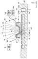
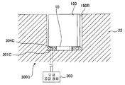
도 2 는 기판 테이블 (22) 및 노즐 부재 (8) 의 근방을 도시한 측단면도, 도 3 은 본 실시형태에 관련된 기판 테이블 (22) 을 도시한 사시도이다. 도 1, 도 2, 및 도 3 에 도시하는 바와 같이, 본 실시형태에 있어서, 기판 테이블 (22) 에는, 진동 부재 (150) 가 탑재되어 있다. 기판 테이블 (22) 은, 종단 광학 소자 (11) 의 사출측에서 이동할 수 있고, 그 기판 테이블 (22) 에 탑재되어 있는 진동 부재 (150) 도, 종단 광학 소자 (11) 의 사출측에서 이동할 수 있다. 진동 부 재 (150) 는 로드 형상의 부재이다. 본 실시형태에서는, 진동 부재 (150) 는 석영으로 형성되어 있다. 기판 테이블 (22) 은 제 1 오목부 (22R) 와는 별도의 제 2 오목부 (150R) 를 갖고, 진동 부재 (150) 는 제 2 오목부 (150R) 에 배치되어 있다. 제 2 오목부 (150R) 의 상단 주위에는, 기판 테이블 (22) 의 상면 (24) 이 배치되어 있다.FIG. 2 is a side sectional view showing the vicinity of the substrate table 22 and the
진동 부재 (150) 는, 종단 광학 소자 (11) 의 하면 (11A) 및 노즐 부재 (8) 의 하면 (8A) 과 대향할 수 있는 상면 (151) 을 갖는다. 본 실시형태에서는, 진동 부재 (150) 의 상면 (151) 은 평탄하다. 본 실시형태에서는, 진동 부재 (150) 는 상면 (151) 과 XY 평면이 거의 평행해지도록, 제 2 오목부 (150R) 에 배치된다. 단, 진동 부재 (150) 의 상면 (151) 은 곡면이어도 되고, XY 평면에 대해 경사져 있어도 된다.The vibrating
제 2 오목부 (150R) 에 배치된 진동 부재 (150) 의 상면 (151) 주위에는, 기판 테이블 (22) 의 상면 (24) 이 배치된다. 진동 부재 (150) 의 상면 (151) 과 기판 테이블 (22) 의 상면 (24) 은, 소정 갭 (G) 을 사이에 두고 배치되어 있다. 즉, 기판 테이블 (22) 의 상면 (24) 을 형성하는 부재와 진동 부재 (151) 사이에는 갭이 형성되어 있다. 본 실시형태에서는, 갭 (G) 은, 예를 들어 0.1 ㎜ 정도이다.The
또한, 본 실시형태에서는, 진동 부재 (150) 의 상면 (151) 과, 기판 테이블 (22) 의 상면 (24) 은, 동일 평면 내 (XY 평면 내) 에 배치되어 있다. 바꿔 말하면, 진동 부재 (150) 의 상면 (151) 과, 기판 테이블 (22) 의 상면 (24) 은 거의 면일하다. 또한, 진동 부재 (150) 의 상면 (151) 및 기판 테이블 (22) 의 상면 (24) 은, 기판 테이블 (22) 의 유지부 (23) 에 유지된 기판 (P) 의 표면과 거의 면일하다.In addition, in this embodiment, the
진동 부재 (150) 에는, 진동 발생 장치 (10) 가 접속되어 있다. 본 실시형태에서는, 진동 발생 장치 (10) 는 진동 부재 (150) 의 하면 (152) 에 접속되어 있다. 진동 발생 장치 (10) 는, 제 2 오목부 (150R) 의 내측에 배치되어 있고, 그 제 2 오목부 (150R) 의 내측에서, 진동 부재 (150) 의 하면 (152) 에 접속되어 있다.The
진동 발생 장치 (10) 는 진동 부재 (150) 를 진동시킨다. 진동 발생 장치 (10) 는, 초음파 발생 장치를 포함하고, 진동 부재 (150) 에 초음파를 준다. 본 실시형태에 있어서, 진동 발생 장치 (10) 는, 수정 진동자 또는 PZT (지르콘산 티탄산납) 와 같은 압전 소자와, 압전 소자를 구동하는 회로를 포함한다. 상기 압전 소자 대신에, 페라이트 코어에 코일을 권회한 자왜형 진동자를 사용해도 된다. 진동 발생 장치 (10) 는 제어 장치 (7) 에 의해 제어되고, 노광 장치 (EX) 의 제어 장치 (7) 는, 진동 발생 장치 (10) 를 사용하여 진동 부재 (150) 를 진동시킨다. 압전 소자의 구동 회로는 제어 장치 (7) 에 장착되어 있어도 된다. 이하의 설명에서, 진동 발생 장치 (10) 를 적절히 초음파 발생 장치 (10) 라고 한다.The
도 2 에 도시하는 바와 같이, 노즐 부재 (8) 는 종단 광학 소자 (11) 의 근방에 배치되어 있다. 노즐 부재 (8) 는 고리 형상 부재로서, 종단 광학 소자 (11) (노광광 (EL) 의 광로 공간) 주위에 배치되어 있다. 예를 들어 기판 (P) 상에 제 1 액침 공간 (LS1) 을 형성하는 경우, 종단 광학 소자 (11) 의 하면 (11A) 및 노즐 부재 (8) 의 하면 (8A) 과 기판 (P) 의 표면 사이에 제 1 액체 (LQ) 가 유지된다.As shown in FIG. 2, the
노즐 부재 (8) 는, 제 1 액체 (LQ) 를 공급할 수 있는 공급구 (81) 와, 제 1 액체 (LQ) 를 회수할 수 있는 회수구 (82) 를 갖는다. 회수구 (82) 는 노즐 부재 (8) 의 하면 (8A) 일부에 배치되어 있다. 또한, 종단 광학 소자 (11) 의 하면 (11A) 과 대향하는 노즐 부재 (8) 의 일부에 개구 (8K) 가 형성되어 있다. 종단 광학 소자 (11) 의 하면 (11A) 으로부터 사출된 노광광 (EL) 은, 개구 (8K) 를 통과하여 기판 (P) 에 조사된다.The
노광 장치 (EX) 는, 제 1 액체 (LQ) 를 발생하는 제 1 액체 공급 장치 (86) 와, 제 2 액체 (LC) 를 발생하는 제 2 액체 공급 장치 (96) 와, 액체를 회수할 수 있는 액체 회수 장치 (89) 를 구비하고 있다. 제 1 액체 공급 장치 (86), 제 2 액체 공급 장치 (96), 및 액체 회수 장치 (89) 는 제어 장치 (7) 로 제어된다. 제 1 액체 공급 장치 (86) 와 공급구 (81) 는, 노즐 부재 (8) 의 내부에 형성된 공급 유로 (84), 및 공급관 (85) 을 통하여 접속되어 있다. 액체 회수 장치 (89) 와 회수구 (82) 는, 노즐 부재 (8) 의 내부에 형성된 회수 유로 (87) 및 회수관 (88) 을 통하여 접속되어 있다. 제 2 액체 공급 장치 (96) 는, 유로 전환 기구 (160) 를 통하여 공급관 (85) 과 접속되어 있다. 유로 전환 기구 (160) 는 제어 장치 (7) 로 제어된다.The exposure apparatus EX can recover the first
상기 서술한 바와 같이, 제 1 액체 (LQ) 는 노광용 액체이다. 제 1 액체 공급 장치 (86) 는, 청정하고 온도 조정된 제 1 액체 (LQ) 를, 공급구 (81) 를 향하여 송출할 수 있다. 제 2 액체 (LC) 는 클리닝용 액체이다. 제 2 액체 공급 장치 (96) 는 제 2 액체 (LC) 를 공급구 (81) 를 향하여 송출할 수 있다. 액체 회수 장치 (89) 는 진공 시스템을 포함하고, 제 1 액체 (LQ) 및 제 2 액체 (LC) 를 회수할 수 있다.As mentioned above, the 1st liquid LQ is a liquid for exposure. The 1st
본 실시형태에 있어서, 제어 장치 (7) 는, 유로 전환 기구 (160), 제 1 액체 공급 장치 (86), 및 제 2 액체 공급 장치 (96) 를 제어하여, 제 1 액체 공급 장치 (86) 로부터 송출된 제 1 액체 (LQ) 가 공급구 (81) 로 공급될 때, 제 2 액체 공급 장치 (96) 로부터 공급구 (81) 로의 제 2 액체 (LC) 의 공급을 정지시킬 수 있다. 또한, 제어 장치 (7) 는, 제 2 액체 공급 장치 (96) 로부터 송출된 제 2 액체 (LC) 가 공급구 (81) 에 공급될 때, 제 1 액체 공급 장치 (86) 로부터 공급구 (81) 로의 제 1 액체 (LQ) 의 공급을 정지시킬 수 있다.In this embodiment, the control apparatus 7 controls the flow
예를 들어, 제 1 액체 (LQ) 로 제 1 액침 공간 (LS1) 을 형성하기 위해서, 제어 장치 (7) 는, 제 2 액체 공급 장치 (96) 로부터 공급구 (81) 로의 제 2 액체 (LC) 의 공급을 정지시키고, 제 1 액체 공급 장치 (86) 로부터 제 1 액체 (LQ) 를 송출한다. 제 1 액체 공급 장치 (86) 로부터 송출된 제 1 액체 (LQ) 는, 공급관 (85), 및 노즐 부재 (8) 의 공급 유로 (84) 를 흐른 후, 공급구 (81) 에 공급된다. 공급구 (81) 는, 제 1 액체 (LQ) 로 제 1 액침 공간 (LS1) 을 형성하기 위해서, 제 1 액체 공급 장치 (86) 로부터의 제 1 액체 (LQ) 를 공급한다. 또한, 액체 회수 장치 (89) 의 작동에 의해, 회수구 (82) 로부터 회수된 제 1 액체 (LQ) 는, 노즐 부재 (8) 의 회수 유로 (87) 를 흐른 후, 회수관 (88) 을 통하여 액체 회수 장치 (89) 에 회수된다. 제어 장치 (7) 는, 공급구 (81) 를 사용하는 제 1 액체 (LQ) 의 공급 동작과 병행하여, 회수구 (82) 를 사용하는 제 1 액체 (LQ) 의 회수 동작을 실행함으로써, 제 1 액침 공간 (LS1) 을 형성한다.For example, in order to form the first liquid immersion space LS1 with the first liquid LQ, the control device 7 includes the second liquid LC from the second
또한, 제 2 액체 (LC) 로 제 2 액침 공간 (LS2) 을 형성하기 위해서, 제어 장치 (7) 는, 제 1 액체 공급 장치 (86) 로부터 공급구 (81) 로의 제 1 액체 (LQ) 의 공급을 정지시키고, 제 2 액체 공급 장치 (96) 로부터 제 2 액체 (LC) 를 송출한다. 제 2 액체 공급 장치 (96) 로부터 송출된 제 2 액체 (LC) 는, 공급관 (85), 및 노즐 부재 (8) 의 공급 유로 (84) 를 흐른 후, 공급구 (81) 에 공급된다. 공급구 (81) 는, 제 2 액체 (LC) 로 제 2 액침 공간 (LS2) 을 형성하기 위해서, 제 2 액체 공급 장치 (96) 로부터의 제 2 액체 (LC) 를 공급한다. 또한, 액체 회수 장치 (89) 의 작동에 의해, 회수구 (82) 로부터 회수된 제 2 액체 (LC) 는, 노즐 부재 (8) 의 회수 유로 (87) 를 흐른 후, 회수관 (88) 을 통하여 액체 회수 장치 (89) 에 회수된다. 제어 장치 (7) 는, 공급구 (81) 를 사용하는 제 2 액체 (LC) 의 공급 동작과 병행하여, 회수구 (82) 를 사용하는 제 2 액체 (LC) 의 회수 동작을 실행함으로써, 제 2 액침 공간 (LS2) 을 형성한다.In addition, in order to form the second liquid immersion space LS2 with the second liquid LC, the control device 7 includes the first liquid LQ from the first
이와 같이, 본 실시형태에서는, 공급구 (81) 는 제 1 액체 (LQ) 및 제 2 액체 (LC) 의 각각을 공급할 수 있다.Thus, in this embodiment, the
본 실시형태에서는, 제 1 액체 (LQ) 로서 물 (순수) 을 사용한다.In this embodiment, water (pure water) is used as 1st liquid LQ.
또한, 본 실시형태에서는, 제 2 액체 (LC) 로서 제 1 액체 (LQ) 와 상이한 것을 사용한다. 본 실시형태에서는, 제 2 액체 (LC) 로서 수소 가스를 물에 용해시킨 수소수 (수소 용해수) 를 사용한다.In addition, in this embodiment, what is different from 1st liquid LQ is used as 2nd liquid LC. In the present embodiment, hydrogen water (hydrogen dissolved water) in which hydrogen gas is dissolved in water is used as the second liquid LC.
또한, 제 2 액체 (LC) 로서 오존 가스를 물에 용해시킨 오존수 (오존 용해수), 질소 가스를 물에 용해시킨 질소수 (질소 용해수), 아르곤 가스를 물에 용해시킨 아르곤수 (아르곤 용해수), 이산화탄소 가스를 물에 용해시킨 이산화탄소수 (이산화탄소 용해수) 등, 소정 가스를 물에 용해시킨 용해 가스 제어수를 사용해도 된다. 또한, 대기압 하의 용해도 이상으로 가스를 용해시킨 가스 과포화수여도 된다. 또한, 제 2 액체 (LC) 로서 과산화 수소를 물에 첨가한 과산화 수소수, 염산 (차아염소산) 을 물에 첨가한 염소 첨가수, 암모니아를 물에 첨가한 암모니아수, 콜린을 용해시킨 콜린수, 및 황산을 물에 첨가한 황산 첨가수 등, 소정 약액을 물에 첨가한 약액 첨가수를 사용해도 된다. 또한, 제 2 액체 (LC) 로서 에탄올 및 메탄올 등의 알코올류, 에테르류, 감마 부티로락톤, 시너류, 계면 활성제, HFE 등의 불소계 용제를 사용해도 된다.In addition, ozone water (ozone dissolved water) in which ozone gas is dissolved in water as the second liquid (LC), nitrogen water (nitrogen dissolved water) in which nitrogen gas is dissolved in water, and argon water (argon dissolved in argon gas) Water) and dissolved gas control water in which a predetermined gas is dissolved in water, such as carbon dioxide water (carbon dioxide dissolved water) in which carbon dioxide gas is dissolved in water. Moreover, the gas supersaturated water which melt | dissolved gas more than the solubility under atmospheric pressure may be sufficient. In addition, hydrogen peroxide which added hydrogen peroxide to water as a 2nd liquid LC, chlorine-added water which added hydrochloric acid (hypochlorous acid) to water, ammonia water which added ammonia to water, choline water which dissolved choline, and You may use the chemical liquid addition water which added the predetermined chemical liquid to water, such as the sulfuric acid addition water which added sulfuric acid to water. As the second liquid LC, fluorine-based solvents such as alcohols such as ethanol and methanol, ethers, gamma butyrolactone, thinners, surfactants, and HFE may be used.
본 실시형태에 있어서, 진동 부재 (150) 의 상면 (151) 은 제 1 액체 (LQ) 및 제 2 액체 (LC) 에 대해 발액성을 갖는다. 제 1 액체 (LQ) 및 제 2 액체 (LC) 에 대한 진동 부재 (150) 의 상면 (151) 의 접촉각은 90 도 이상이다. 본 실시형태에서는, 진동 부재 (150) 의 상면 (151) 은, 예를 들어 불소계 수지 (PTFE, PFA 등) 등, 발액성을 갖는 재료의 막으로 형성되어 있다. 또한, 진동 부재 (150) 의 측면도, 제 1 액체 (LQ) 및 제 2 액체 (LC) 에 대해 발액성을 갖는 것이 바람직하다.In the present embodiment, the
마찬가지로, 기판 테이블 (22) 의 상면 (24) 은, 제 1 액체 (LQ) 및 제 2 액체 (LC) 에 대해 발액성을 갖는다. 제 1 액체 (LQ) 및 제 2 액체 (LC) 에 대한 기판 테이블 (22) 의 상면 (24) 의 접촉각은 90 도 이상이다. 본 실시형태에서는, 기판 테이블 (22) 의 상면 (24) 은, 예를 들어 불소계 수지 (PTFE, PFA 등) 등, 발액성을 갖는 재료의 막으로 형성되어 있다. 또한, 기판 테이블 (22) 의 제 2 오목부 (150R) 의 내측면 (진동 부재 (150) 의 측면과 대향하는 면) 도, 제 1 액체 (LQ) 및 제 2 액체 (LC) 에 대해 발액성을 갖는 것이 바람직하다.Similarly, the
마찬가지로, 계측 테이블 (32) 의 상면 (34) 은, 제 1 액체 (LQ) 및 제 2 액체 (LC) 에 대해 발액성을 갖는다. 제 1 액체 (LQ) 및 제 2 액체 (LC) 에 대한 계측 테이블 (32) 의 상면 (34) 의 접촉각은 90 도 이상이다. 본 실시형태에서는, 계측 테이블 (32) 의 상면 (34) 은, 예를 들어 불소계 수지 (PTFE, PFA 등) 등, 발액성을 갖는 재료의 막으로 형성되어 있다. 또한, 진동 부재 (150), 기판 테이블 (22), 계측 테이블 (32) 에서 사용되는 발액성의 막은, 각각 동일한 재료 (물질) 로 구성되어 있어도 되고, 상이한 재료 (물질) 로 구성되어 있어도 된다.Similarly, the
다음으로, 상기 서술한 구성을 갖는 노광 장치 (EX) 를 사용하여 기판 (P) 을 노광하는 방법에 대해 설명한다.Next, the method to expose the board | substrate P using the exposure apparatus EX which has the structure mentioned above is demonstrated.
예를 들어, 제어 장치 (7) 는, 제 2 구동 시스템 (5) 을 사용하여, 노즐 부재 (8) 와 대향하는 위치에 계측 테이블 (32) 을 배치하고, 노즐 부재 (8) 와 계측 테이블 (32) 사이에 제 1 액체 (LQ) 로 제 1 액침 공간 (LS1) 을 형성한다. 그리고, 제어 장치 (7) 는, 제 1 액침 공간 (LS1) 의 제 1 액체 (LQ) 를 통하여, 계측 테이블 (32) 에 배치된 각종 계측기에 의한 계측을 실행한다. 그리고, 제어 장치 (7) 는, 그 계측기의 계측 결과에 기초하여, 예를 들어 투영 광학계 (PL) 의 결상 특성 등, 기판 (P) 을 노광할 때에는 노광 조건을 조정하여, 기판 (P) 의 노광 동작을 개시한다. 기판 (P) 을 노광할 때에는, 제어 장치 (7) 는 제 2 구동 시스템 (5) 을 사용하여, 노즐 부재 (8) 와 대향하는 위치에 기판 (P) 을 유지한 기판 스테이지 (2) 를 배치하고, 노즐 부재 (8) 와 기판 테이블 (22) (기판 (P)) 사이에 제 1 액침 공간 (LS1) 을 형성한다.For example, the control apparatus 7 arrange | positions the measurement table 32 in the position which opposes the
본 실시형태에서는, 예를 들어 유럽 특허 출원 공개 공보 제1,713,113호, 미국 특허 공개 공보 제2006/0023186호 등에 개시되어 있는 바와 같이, 제어 장치 (7) 는, 기판 테이블 (22) 및 계측 테이블 (32) 중 적어도 일방이 종단 광학 소자 (11) 및 노즐 부재 (8) 사이에 제 1 액체 (LQ1) 를 유지할 수 있는 공간을 계속 형성하도록, 기판 테이블 (22) 의 상면 (24) 과 계측 테이블 (32) 의 상면 (34) 을 접근 또는 접촉시킨 상태에서, 기판 테이블 (22) 의 상면 (24) 및 계측 테이블 (32) 의 상면 (34) 중 적어도 일방과 종단 광학 소자 (11) 의 하면 (11A) 및 노즐 부재 (8) 의 하면 (8A) 을 대향시키면서, 종단 광학 소자 (11) 및 노즐 부재 (8) 에 대해, 기판 테이블 (22) 과 계측 테이블 (32) 을 XY 방향으로 동기 이동시킨다. 이로써, 제어 장치 (7) 는, 제 1 액체 (LQ) 의 누출을 억제하면서, 기판 테이블 (22) 의 상면 (24) 과 계측 테이블 (32) 의 상면 (34) 사이에서 제 1 액체 (LQ) 의 제 1 액침 공간 (LS1) 을 이동할 수 있다. 또한, 기판 테이블 (22) 의 상면 (24) 과 계측 테이블 (32) 의 상면 (34) 사이에서 제 1 액체 (LQ1) 의 제 1 액침 공간 (LS1) 을 이동할 때에, 기판 테이블 (22) 의 상면 (24) 과 계측 테이블 (32) 의 상면 (34) 은 거의 동일한 높이 (면일) 가 되도록 조정된다.In this embodiment, as disclosed, for example, in European Patent Application Publication No. 1,713,113, US Patent Publication No. 2006/0023186, and the like, the control device 7 includes a substrate table 22 and a measurement table 32. ), The
그리고, 제어 장치 (7) 는, 제 1 액침 공간 (LS1) 의 제 1 액체 (LQ) 를 통하여, 마스크 (M) 로부터의 노광광 (EL) 을 기판 (P) 에 조사한다. 이로써, 마스크 (M) 패턴의 이미지가 기판 (P) 에 투영되어 기판 (P) 이 노광된다.And the control apparatus 7 irradiates the board | substrate P with exposure light EL from the mask M through the 1st liquid LQ of the 1st immersion space LS1. Thereby, the image of the mask M pattern is projected on the board | substrate P, and the board | substrate P is exposed.
제어 장치 (7) 는, 기판 (P) 의 노광이 종료된 후, 제 1 액침 공간 (LS1) 을 계측 테이블 (32) 상으로 이동한다. 그리고, 제어 장치 (7) 는, 노광이 종료된 기판 (P) 을 유지한 기판 테이블 (22) 을 소정의 기판 교환 위치로 이동하고, 노광이 종료된 기판 (P) 을 기판 테이블 (22) 로부터 반출 (언로드) 함과 함께, 노광해야 할 기판 (P) 을 기판 테이블 (22) 에 반입 (로드) 한다. 또한, 기판 교환 위치에 있어서의 기판 교환 중, 제어 장치 (7) 는, 필요에 따라 계측 테이블 (32) 을 사용한 계측 동작을 제 1 액침 공간 (LS1) 의 제 1 액체 (LQ) 를 통하여 실행한다. 기판 테이블 (22) 에 대한 기판 (P) 의 반입이 종료된 후, 상기 서술한 바와 같이, 제어 장치 (7) 는, 제 1 액침 공간 (LS1) 을 기판 테이블 (22) (기판 (P)) 상으로 이동하고, 제 1 액침 공간 (LS1) 의 제 1 액체 (LQ) 를 통하여 기판 (P) 을 노광한다. 그리고, 제어 장치 (7) 는, 상기 서술한 동작을 반복하여, 복수의 기판 (P) 을 순차적으로 노광한다.The control apparatus 7 moves the 1st liquid immersion space LS1 on the measurement table 32 after exposure of the board | substrate P is complete | finished. And the control apparatus 7 moves the board | substrate table 22 which hold | maintained the board | substrate P with which exposure was complete | finished to a predetermined board | substrate exchange position, and moves the board | substrate P with which exposure was complete | finished from the board | substrate table 22 to it. In addition to carrying out (unloading), the substrate P to be exposed is loaded into the substrate table 22 (loaded). In addition, during the board exchange in the board | substrate exchange position, the control apparatus 7 performs the measurement operation | movement using the measurement table 32 via the 1st liquid LQ of the 1st immersion space LS1 as needed. . After the carrying in of the board | substrate P with respect to the board | substrate table 22 is complete | finished, as mentioned above, the control apparatus 7 moves the 1st immersion space LS1 to the board | substrate table 22 (substrate P). It moves upward and exposes the board | substrate P through the 1st liquid LQ of the 1st liquid immersion space LS1. And the control apparatus 7 repeats the above-mentioned operation | movement, and exposes several board | substrate P sequentially.
기판 (P) 을 노광할 때, 제 1 액침 공간 (LS1) 의 제 1 액체 (LQ) 는, 기판 (P) 의 표면, 종단 광학 소자 (11) 의 하면 (11A), 및 노즐 부재 (8) 의 하면 (8A) 각각에 접촉한다. 기판 (P) 과 접촉한 제 1 액체 (LQ) 에, 예를 들어 기판 (P) 의 일부 물질 (예를 들어 감광재의 일부) 이 용출될 가능성이 있다. 그 액체 (LQ) 가 종단 광학 소자 (11) 의 하면 (11A), 노즐 부재 (8) 의 하면 (8A) 에 접촉하면, 기판 (P) 으로부터 용출된 물질에 의해, 하면 (11A, 8A) 이 오염될 가능성이 있다. 또한, 기판 (P) 으로부터 용출된 물질에 한정되지 않고, 예를 들어 노광 장치 (EX) 가 놓여져 있는 공간 내를 부유하는 물질 (이물질) 에 의해서도, 그들 이물질이 직접, 하면 (11A, 8A) 에 부착되거나, 제 1 액체 (LQ) 에 혼입됨으로써, 하면 (11A, 8A) 이 오염될 가능성이 있다.When exposing the board | substrate P, the 1st liquid LQ of the 1st immersion space LS1 has the surface of the board | substrate P, the
그래서, 본 실시형태에서는, 제 2 액체 (LC) 를 사용하여, 종단 광학 소자 (11) 및 노즐 부재 (8) 중 적어도 일방을 클리닝한다. 본 실시형태에서는, 종단 광학 소자 (11) 및 노즐 부재 (8) 와, 진동 부재 (150) 의 상면 (151) 사이에 제 2 액체 (LC) 로 제 2 액침 공간 (LS2) 을 형성하고, 그 형성된 제 2 액침 공간 (LS2) 의 제 2 액체 (LC) 에 진동을 줌으로써, 종단 광학 소자 (11) 및 노즐 부재 (8) 의 적어도 일방을 클리닝한다.Therefore, in this embodiment, at least one of the terminal
다음으로, 제 2 액체 (LC) 를 사용하여 종단 광학 소자 (11) 및 노즐 부재 (8) 를 클리닝하는 방법에 대해 설명한다.Next, a method of cleaning the terminal
제 2 액체 (LC) 를 사용하여 종단 광학 소자 (11) 및 노즐 부재 (8) 를 클리닝하기 위해서, 제어 장치 (7) 는, 진동 부재 (150) 가 종단 광학 소자 (11) 와 대향하도록 기판 테이블 (22) 을 이동하고, 종단 광학 소자 (11) 및 노즐 부재 (8) 와 진동 부재 (150) 사이에 제 2 액체 (LC) 로 제 2 액침 공간 (LS2) 을 형성한다. 제 2 액체 (LC) 로 제 2 액침 공간 (LS2) 을 형성하기 위해서, 제어 장치 (7) 는, 공급구 (81) 로부터의 제 1 액체 (LQ) 의 공급을 정지시키고, 공급구 (81) 로부터 제 2 액체 (LC) 를 공급한다. 공급구 (81) 로부터 공급되는 제 2 액체 (LC) 에 의해, 도 4 에 도시하는 바와 같이, 종단 광학 소자 (11) 및 노즐 부재 (8) 와 진동 부재 (150) 사이에 제 2 액침 공간 (LS2) 이 형성된다. 노즐 부재 (8) 는, 공급구 (81) 를 사용하는 제 2 액체 (LC) 의 공급 동작과 병행하여, 회수구 (82) 를 사용하는 제 2 액체 (LC) 의 회수 동작을 실행함으로써, 제 2 액침 공간 (LS2) 을 형성한다. 도 4 에 도시하는 바와 같이, 본 실시형태에서는, XY 평면 내에서의 제 2 액침 공간 (LS2) 의 크기는, 진동 부재 (150) 의 상면 (151) 보다 크고, 제 2 액침 공간 (LS2) 은, 종단 광학 소자 (11) 및 노즐 부재 (8) 와 진동 부재 (150) 및 기판 테이블 (22) 사이에 형성된다.In order to clean the terminal
제어 장치 (7) 는, 제 2 액침 공간 (LS2) 을 형성한 상태에서, 초음파 발생 장치 (10) 에 의해 진동 부재 (150) 를 진동시킨다. 초음파 발생 장치 (10) 는, 진동 부재 (150) 를 진동시킴으로써, 그 진동 부재 (150) 상에 형성되어 있는 제 2 액침 공간 (LS2) 의 제 2 액체 (LC2) 에 초음파 (진동) 를 준다. 본 실시형태에서는, 초음파 발생 장치 (10) 는 20 kHz ∼ 5000 kHz 의 진동을 진동 부재 (150) 에 줄 수 있다. 초음파 발생 장치 (10) 는, 종단 광학 소자 (11) 및 노즐 부재 (8) 와 진동 부재 (150) 및 기판 테이블 (22) 사이에 형성된 제 2 액침 공간 (LS2) 의 제 2 액체 (LC) 에 초음파 (진동) 를 줌으로써, 종단 광학 소자 (11) 및 노즐 부재 (8) 의 적어도 일방에 부착되어 있는 이물질 (오염물) 을 박리시켜, 종단 광학 소자 (11) 및 노즐 부재 (8) 의 적어도 일방을 클리닝한다. 예를 들어, 제 2 액체 (LC) 에 초음파 (진동) 를 줌으로써, 제 2 액체 (LC) 중에 캐비테이션 (미소 기포의 발생과 그 소멸시의 충격파의 발생) 을 발생시킨다. 이 캐비테이션에 의해 종단 광학 소자 (11) 및 노즐 부재 (8) 의 적어도 일방에 부착되어 있는 이물질 (오염물) 을 박리시켜, 종단 광학 소자 (11) 및 노즐 부재 (8) 의 적어도 일방을 클리닝한다.The control apparatus 7 vibrates the vibrating
또한, 초음파 발생 장치 (10) 에 의해 진동 부재 (10) 를 진동시키는 동안 (클리닝 동작 중) 에 제 2 액체 (LC) 의 공급과 회수가 계속되지만, 제 2 액체 (LC) 의 공급과 회수를 일시적 또는 단속적으로 정지시켜도 된다.In addition, while the vibrating
초음파 발생 장치 (10) 에 의해 진동 부재 (10) 를 진동시키는 동안, 기판 테이블 (22) 을 제 2 구동 시스템 (5) 에 의해 XY 평면 내에서 투영 광학계 (PL) 및 노즐 부재 (8) 에 대해 이동시켜도 된다. 이렇게 함으로써, 진동 부재 (150) 의 상면 (151) 의 제 1 액침 공간 (LS1) 및 제 2 액침 공간 (LS2) 에 대한 크기의 상이함에 상관 없이, 노즐 부재 (8) 의 하면 (8A) 및 종단 광학 소자 (11) 의 하면 (11A) 을 보다 균일하고 또한 확실하게 세정할 수 있다. 또한, 기판 테이블 (22) 의 이동시에 진동 부재 (10) 의 진동을 정지시키고, 기판 테이블 (22) 이 소정 위치에서 정지되어 있을 때에만 진동 부재 (10) 를 진동시켜도 된다.While vibrating the vibrating
도 4 에 도시하는 바와 같이, 본 실시형태에서는, 제 2 액체 (LC) 를 사용한 클리닝 동작에 있어서, 기판 테이블 (22) 의 유지부 (23) 에는 더미 기판 (DP) 이 유지된다. 더미 기판 (DP) 은, 노광용 기판 (P) 과는 별도의, 이물질을 방출하기 어려운 높은 청정도를 갖는 (깨끗한) 부재이다. 더미 기판 (DP) 은, 노광용 기판 (P) 과 거의 동일한 외형을 갖고, 유지부 (23) 에 유지할 수 있다. 본 실시형태에서는, 유지부 (23) 는 핀 척 기구를 갖고, 기판 (P) 및 더미 기판 (DP) 의 각각을 착탈할 수 있도록 유지한다. 더미 기판 (DP) 의 표면은, 제 2 액체 (LC) 에 대해 발액성을 가지고 있다. 또한, 유지부 (23) 로 더미 기판 (DP) 을 유지하지 않고, 유지부 (23) 를 노출시킨 상태에서, 클리닝용 액체 (LC) 를 사용한 클리닝 동작을 실행할 수도 있다.As shown in FIG. 4, in the present embodiment, in the cleaning operation using the second liquid LC, the dummy substrate DP is held in the holding
이상 설명한 바와 같이, 본 실시형태에 의하면, 종단 광학 소자 (11) 및 노즐 부재 (8) 등, 기판 테이블 (22) 과의 사이에서 액침 공간을 형성할 수 있는 액침 부재를 양호하게 클리닝할 수 있다. 따라서, 종단 광학 소자 (11) 및 노즐 부재 (8) 의 오염에서 기인되는 노광 장치 (EX) 의 성능의 열화를 억제할 수 있다.As explained above, according to this embodiment, the liquid immersion member which can form the liquid immersion space between the board | substrate table 22, such as the terminal
본 실시형태에서는, 제 2 액침 공간 (LS2) 의 제 2 액체 (LC) 에 초음파를 부여하는 초음파 발생 장치 (10) 를 설치하였으므로, 클리닝 효과를 높일 수 있다. 본 실시형태에서는, 클리닝에 적절한 제 2 액체 (LC) (수소수) 와 초음파의 상승 효과에 의해, 종단 광학 소자 (11) 및 노즐 부재 (8) 를 양호하게 클리닝할 수 있다.In this embodiment, since the ultrasonic
또한, 본 실시형태에서는, 제 2 액침 공간 (LS2) 의 제 2 액체 (LC) 에 초음파를 주기 위해서, 기판 테이블 (22) 에 탑재할 수 있는 소형의 진동 부재 (150) 를 진동시키고 있다. 이로써, 진동 부재 (150) 를 높은 주파수 (진동수) 로 원 활하게 진동시킬 수 있고, 제 2 액침 공간 (LS2) 의 제 2 액체 (LC) 에 높은 주파수의 초음파를 원활하게 줄 수 있다. 제 2 액침 공간 (LS2) 의 제 2 액체 (LC) 에 부여하는 초음파의 주파수가 높은 편이, 보다 양호한 클리닝 효과가 얻어지는 경우에는, 기판 테이블 (22) 에 탑재된 진동 부재 (150) 를, 예를 들어 1 MHz 이상의 높은 주파수 (진동수) 로 진동시키는 것이 유효하다. 혹은, 초음파 발생 장치 (10) 의 압전 소자의 구동 회로 또는 제어 장치 (7) 에 의해 진동 부재 (150) 의 진동 주파수를 연속적으로 변조시키면서 혹은 복수의 주파수로 전환하면서 진동시켜도 된다. 이렇게 함으로써 종단 광학 소자 (11) 및 노즐 부재 (8) 에 부착된 복수종의 이물질 중 특정한 단일 주파수만으로는 이탈되기 어려운 이물질도 이탈시키기 쉬워져, 초음파에 의한 캐비테이션의 효과가 더욱 유효해진다.In addition, in this embodiment, in order to give an ultrasonic wave to the 2nd liquid LC of the 2nd liquid immersion space LS2, the
또한, 본 실시형태에서는, 진동 부재 (150) 의 상면 (151) 과 기판 테이블 (22) 의 상면 (24) 은 면일하므로, 제 2 액침 공간 (LS2) 을 양호하게 형성할 수 있다.In addition, in this embodiment, since the
또한, 진동 부재 (150) 와 기판 테이블 (22) 은 소정 갭 (G) 을 사이에 두고 배치되어 있으므로, 진동 부재 (150) 는 원활하게 진동할 수 있다. 또한, 진동 부재 (150) 와 기판 테이블 (22) 은, 소정 갭 (G) 을 사이에 두고 배치되어 있으므로, 진동 부재 (150) 의 진동이 기판 테이블 (22) 에 악영향을 주지 않는다. 또한, 진동 부재 (150) (상면 (151)) 와 기판 테이블 (22) (상면 (24)) 사이의 갭 (G) 은 미소 (약 0.1 ㎜) 하고, 또한 진동 부재 (150) 의 상면 (151) 및 기판 테이블 (22) 의 상면 (24) 은, 제 1 액체 (LQ), 및 제 2 액체 (LC) 에 대해 발액성을 가지고 있으므로, 상면 (151, 24) 에 제 1 액체 (LQ) 및 제 2 액체 (LC) 가 잔류하거나 진동 부재 (150) (상면 (151)) 와 기판 테이블 (22) (상면 (24)) 사이의 갭 (G) 으로부터 기판 테이블 (22) 의 내부에 액체가 침입하는 것을 억제할 수 있다.In addition, since the
또한, 진동 부재 (150) 와 기판 테이블 (22) 사이에, 기판 테이블 (22) 의 내부에 액체가 침입하는 것을 억제하는 시일 부재를 배치할 수 있다. 예를 들어, O 링 등, 탄성 (가요성) 을 갖는 시일 부재를 배치함으로써, 진동 부재 (150) 의 진동을 방해하지 않고, 기판 테이블 (22) 의 내부로의 액체의 침입를 억제할 수 있다. 혹은, 제 2 오목부 (150R) 의 개구보다 큰 유연한 시일막을 준비하고, 그 시일막으로 제 2 오목부 (150R) 의 개구를 덮음과 함께 시일막의 이면을 진동 부재 (150) 의 상면 (151) 에 접착시켜도 된다. 이렇게 함으로써, 갭 (G) 에 대한 액체의 침입이 방지되면서, 진동 부재 (150) 의 진동이 액체에 전달된다. 이 경우, 시일막의 재료는 전술한 발액성 재료로 형성하는 것이 바람직하다. 진동 부재 (150) 의 상면 (151) 상에 위치하는 시일막의 일부를 제거하여 진동 부재 (150) 의 상면 (151) 의 일부를 노출시켜도 된다.Moreover, the sealing member can be arrange | positioned between the vibrating
또한, 진동 부재 (150) 와 기판 테이블 (22) 사이의 액체를 회수하는 회수구를 형성할 수 있다. 예를 들어, 제 2 오목부 (150R) 의 내측 (제 2 오목부 (150R) 를 구획하는 내벽 중 측면 또는 저면) 에 진동 부재 (150) 를 둘러싸도록 회수구를 형성함으로써, 진동 부재 (150) 와 기판 테이블 (22) 사이에 침입한 액체를 양호하게 회수할 수 있다.In addition, a recovery port for recovering the liquid between the
또한, 본 실시형태에서는, 진동 부재 (150) 가 기판 테이블 (22) 에 1 개만 탑재되어 있는 경우를 예로 들어 설명했으나, 기판 테이블 (22) 의 복수 위치의 각각에 탑재되어 있어도 된다.In addition, in this embodiment, although the case where only one
또한, 본 실시형태에서는, 노즐 부재 (8) 에 형성된 공급구 (81) 가 제 2 액체 (LC) 와 제 1 액체 (LQ) 양방을 공급할 수 있는 경우를 예로 들어 설명했는데, 노즐 부재 (8) 에 제 2 액체 (LC) 를 공급하는 공급구와, 제 1 액체 (LQ) 를 공급하는 공급구를 따로 따로 형성해도 된다. 마찬가지로, 노즐 부재 (8) 에 제 1 액체 (LQ) 를 회수하기 위한 회수구과, 제 2 액체 (LC) 를 회수하기 위한 회수구를 따로 따로 설치해도 된다.In addition, in this embodiment, the case where the
<제 2 실시형태><2nd embodiment>
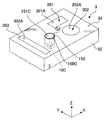
다음으로, 제 2 실시형태에 대해 설명한다. 이하의 설명에 있어서, 상기 서술한 실시형태와 동일 또는 동등한 구성 부분에 대해서는 동일한 부호를 부여하여, 그 설명을 간략히 하거나 혹은 생략한다. 상기 서술한 제 1 실시형태에 있어서는, 제 2 액침 공간 (LS2) 을 형성하기 위한 제 2 액체 (LC) 를 공급하는 공급구 (81) 가 노즐 부재 (8) 에 배치되어 있는 경우를 예로 들어 설명했는데, 제 2 실시형태의 특징적인 부분은, 제 2 액침 공간 (LS2) 을 형성하기 위한 제 2 액체 (LC) 를 공급하는 공급구 (81B) 가 기판 테이블 (22) 에 배치되어 있는 점에 있다.Next, 2nd Embodiment is described. In the following description, the same code | symbol is attached | subjected about the component part same or equivalent to embodiment mentioned above, and the description is simplified or abbreviate | omitted. In 1st Embodiment mentioned above, the case where the
도 5 는 제 2 실시형태에 관련된 기판 테이블 (22) 의 근방을 도시한 단면도, 도 6 은 제 2 실시형태에 관련된 기판 테이블 (22) 을 도시한 사시도이다. 도 5 및 도 6 에 도시하는 바와 같이, 제 2 실시형태에 관련된 노광 장치 (EX) 는, 제 2 액체 (LC) 를 공급하기 위한 기판 테이블 (22) 에 배치된 공급구 (81B) 를 구 비한다. 공급구 (81B) 는, 제 2 액체 (LC) 로 제 2 액침 공간 (LS2) 을 형성하기 위해서, 제 2 액체 (LC) 를 공급한다.5 is a sectional view showing the vicinity of the substrate table 22 according to the second embodiment, and FIG. 6 is a perspective view showing the substrate table 22 according to the second embodiment. As shown to FIG. 5 and FIG. 6, the exposure apparatus EX which concerns on 2nd Embodiment has the
본 실시형태에서는, 공급구 (81B) 는, 제 2 오목부 (150R) 주위에 복수 배치되어 있다. 공급구 (81B) 의 각각은, 제 2 액체 (LC) 를 송출할 수 있는 제 2 액체 공급 장치 (96) 와 유로를 통하여 접속되어 있다. 기판 테이블 (22) 에 배치된 공급구 (81B) 로부터 공급된 제 2 액체 (LC) 에 의해서도, 종단 광학 소자 (11) 및 노즐 부재 (8) 와 진동 부재 (150) 및 기판 테이블 (22) 사이에 제 2 액침 공간 (LS2) 을 양호하게 형성할 수 있다.In the present embodiment, a plurality of
또한, 기판 테이블 (22) (예를 들어 제 2 오목부 (150R) 주위) 에 제 2 액체 (LC) 를 회수하는 회수구를 형성할 수 있다. 회수구는, 제 2 오목부 (150R) 에 대해 공급구 (81B) 의 더욱 외측에, 하나 또는 그 이상 설치할 수 있다.Moreover, the recovery port which collect | recovers the 2nd liquid LC can be formed in the board | substrate table 22 (for example, around 2nd recessed
또한, 기판 테이블 (22) 에 설치되는 제 2 액체 (LC) 용의 공급구, 및 회수구의 적어도 일방을 제 2 오목부 (150R) 주위에 연속적으로 형성해도 된다.Moreover, you may form continuously the 2nd recessed
또한, 기판 테이블 (22) 에 제 2 액체 (LC) 용 공급구, 및 회수구의 적어도 일방이 설치되어 있는 경우, 제 2 액체 (LC) 를 사용하는 클리닝시에 노즐 부재 (8) 에 설치되어 있는 공급구 (81), 회수구 (82) 의 적어도 일방을 사용하여 제 2 액체 (LC) 를 공급 및/또는 회수해도 되고, 사용하지 않아도 된다. 또한, 제 2 액체 (LC) 에 의한 클리닝 종료시에, 공급구 (81), 회수구 (82) 를 사용하여 제 1 액체 (LQ) 를 공급 및 회수함으로써, 기판 테이블 (22), 종단 광학 소자 (11) 및 노즐 부재 (8) 에 부착된 제 2 액체 (LC) 를 헹굼 (린스) 해도 된다.Moreover, when at least one of the supply port for 2nd liquid LC and the recovery port is provided in the board | substrate table 22, it is provided in the
<제 3 실시형태>Third Embodiment
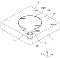
다음으로, 제 3 실시형태에 대해 설명한다. 이하의 설명에 있어서, 상기 서술한 실시형태와 동일 또는 동등한 구성 부분에 대해서는 동일한 부호를 부여하여, 그 설명을 간략히 하거나 혹은 생략한다. 상기 서술한 제 1, 제 2 실시형태에 있어서는, 진동 부재 (150) 가 기판 테이블 (22) 에 탑재되어 있는 경우를 예로 들어 설명했는데, 제 3 실시형태의 특징적인 부분은, 진동 부재 (150) 가 계측 테이블 (32) 에 탑재되어 있는 점에 있다.Next, 3rd Embodiment is described. In the following description, the same code | symbol is attached | subjected about the component part same or equivalent to embodiment mentioned above, and the description is simplified or abbreviate | omitted. In the above-mentioned first and second embodiments, the case where the
도 7 은, 제 3 실시형태에 관련된 계측 테이블 (32) 을 도시한 사시도이다. 도 7 에 있어서, 계측 테이블 (32) 에 진동 부재 (150C) 가 탑재되어 있다. 계측 테이블 (32) 은, 진동 부재 (150C) 를 배치할 수 있는 오목부 (153) 를 갖는다. 오목부 (153) 는, 종단 광학 소자 (11) 의 하면 (11A) 및 노즐 부재 (8) 의 하면 (8A) 과 대향할 수 있는 계측 테이블 (32) 의 상면 (34) 일부에 형성되어 있다. 계측 테이블 (32) 의 상면 (34) 은, 오목부 (153) 에 배치된 진동 부재 (150C) 의 상면 (151C) 주위에 배치된다. 진동 부재 (150C) 와 계측 테이블 (32) 사이에는 갭이 형성되어 있다. 진동 부재 (150C) 의 상면 (151C) 과 계측 테이블 (32) 의 상면 (34) 은, 그들 사이에 갭 (G2) 이 형성되도록 배치되어 있다. 갭 (G2) 은, 예를 들어 0.1 ㎜ 정도이다. 진동 부재 (150C) 를 진동시키기 위한 초음파 발생 장치 (10C) 는, 오목부 (153) 의 내측에서, 진동 부재 (150C) 에 접속되어 있다.FIG. 7: is a perspective view which shows the measurement table 32 which concerns on 3rd Embodiment. In FIG. 7, the
계측 테이블 (32) 의 상면 (34) 은, 평탄하고, XY 평면과 거의 평행이다. 본 실시형태에서는, 진동 부재 (150C) 의 상면 (151C) 과, 계측 테이블 (32) 의 상면 (34) 은 거의 면일하다.The
또한, 진동 부재 (150C) 의 상면 (151C) 및 계측 테이블 (32) 의 상면 (34) 은, 계측 테이블 (32) 에 탑재되어 있는 계측기 (301, 302) 의 표면 (301A, 302A) 과 거의 면일하다. 계측기 (301, 302) 는, 계측 테이블 (32) 에 배치된 유리판 등의 광학 부재와, 그 광학 부재를 통한 광 (노광광 (EL)) 을 수광할 수 있는 수광 소자를 구비하고 있다. 표면 (301A, 302A) 은 계측 테이블 (32) 에 배치된 광학 부재의 표면을 포함한다. 또한, 계측기 (303) 는, 계측 부재를 포함하고, 진동 부재 (150C) 의 상면 (151C) 및 계측 테이블 (32) 의 상면 (34) 은, 계측 부재 (303) 의 표면 (303A) 과 거의 면일하다.In addition, the
본 실시형태에서도, 진동 부재 (150C) 의 상면 (151C) 은, 제 1 액체 (LQ) 및 제 2 액체 (LC) 에 대해 발액성을 갖는다. 제 1 액체 (LQ) 및 제 2 액체 (LC) 에 대한 진동 부재 (150C) 의 상면 (151C) 의 접촉각은 90 도 이상이다. 본 실시형태에서도, 진동 부재 (150C) 의 상면 (151C) 은, 예를 들어 불소계 수지 (PTFE, PFA 등) 등, 발액성을 갖는 재료의 막으로 형성되어 있다. 또한, 진동 부재 (150C) 의 측면도, 제 1 액체 (LQ) 및 제 2 액체 (LC) 에 대해 발액성을 갖는 것이 바람직하다.Also in this embodiment, the
또 상기 서술한 바와 같이, 계측 테이블 (32) 의 상면 (34) 은, 제 1 액체 (LQ) 및 제 2 액체 (LC) 에 대해 발액성을 갖는다. 또한, 진동 부재 (150C), 계측 테이블 (32) 에서 사용되는 발액성의 막은, 각각 동일한 재료 (물질) 로 구성 되어 있어도 되고, 상이한 재료 (물질) 로 구성되어 있어도 된다.Moreover, as mentioned above, the
클리닝 동작을 실행하는 경우, 제어 장치 (7) 는, 종단 광학 소자 (11) 및 노즐 부재 (8) 와 진동 부재 (150C) 및 계측 테이블 (32) 을 대향시켜 제 2 액침 공간 (LS2) 을 형성한 상태에서, 계측 테이블 (32) 에 탑재되어 있는 진동 부재 (150C) 를, 그 진동 부재 (150C) 에 접속되어 있는 초음파 발생 장치 (10C) 로 진동시킨다. 이로써, 제 2 액침 공간 (LS2) 의 제 2 액체 (LC) 에 초음파를 줄 수 있어, 종단 광학 소자 (11), 노즐 부재 (8) 를 양호하게 클리닝할 수 있다. 또한, 클리닝 동작 중에 제 2 액체 (LC) 의 공급과 회수가 계속되지만, 제 2 액체 (LC) 의 공급과 회수를 일시적 또는 단속적으로 정지시켜도 된다.When performing the cleaning operation, the controller 7 forms the second liquid immersion space LS2 by opposing the terminal
초음파 발생 장치 (10C) 에 의해 진동 부재 (150C) 를 진동시키는 동안, 계측 테이블 (32) 을 제 2 구동 시스템 (5) 에 의해 XY 평면 내에서 투영 광학계 (PL) 및 노즐 부재 (8) 에 대해 이동시켜도 된다. 이렇게 함으로써, 진동 부재 (150C) 의 상면 (151) 의 제 1 액침 공간 (LS1) 및 제 2 액침 공간 (LS2) 에 대한 크기의 상이함에 상관 없이, 노즐 부재 (8) 의 하면 (8A) 및 종단 광학 소자 (11) 의 하면 (11A) 을 보다 균일하고 또한 확실하게 세정할 수 있다. 또한, 계측 테이블 (32) 의 이동시에 진동 부재 (150C) 의 진동을 정지시키고, 계측 테이블 (32) 이 소정 위치에서 정지되어 있을 때에만 진동 부재 (10) 를 진동시켜도 된다.While vibrating the vibrating
또한, 진동 부재 (150C) 와 계측 테이블 (32) 은 갭 (G2) 을 사이에 두고 배치되어 있으므로, 진동 부재 (150C) 는 원활하게 진동할 수 있다. 또한, 진동 부 재 (150C) 와 계측 테이블 (22) 은, 갭 (G2) 을 사이에 두고 배치되어 있으므로, 진동 부재 (150C) 의 진동이 계측 테이블 (22) 에 악영향을 주지 않는다. 또한, 진동 부재 (150C) 의 진동이 계측기 (301, 302) 에 전달되지 않도록, 계측 테이블 (32) 에 방진 기구를 설치해도 된다. 또한, 진동 부재 (150) (상면 (151)) 와 기판 테이블 (22) (상면 (24)) 사이의 갭 (G2) 은 미소 (약 0.1 ㎜) 하고, 또한 진동 부재 (150C) 의 상면 (151C) 및 계측 테이블 (32) 의 상면 (34) 은, 제 1 액체 (LQ), 및 제 2 액체 (LC) 에 대해 발액성을 가지고 있으므로, 상면 (151C, 34) 에 제 1 액체 (LQ) 및 제 2 액체 (LC) 가 잔류하거나, 진동 부재 (150C) (상면 (151C)) 와 계측 테이블 (32) (상면 (34)) 사이의 갭 (G2) 으로부터 계측 테이블 (32) 의 내부에 액체가 침입하는 것을 억제할 수 있다.Moreover, since the
제 2 액침 공간 (LS2) 을 형성하기 위한 제 2 액체 (LC) 의 공급은, 제 1 실시형태와 동일하게 노즐 부재 (8) 에 배치되어 있는 공급구 (81) 로부터 공급할 수 있다. 또한, 계측 테이블 (32) (예를 들어 오목부 (153) 주위) 에 제 2 액체 (LC) 를 공급하는 공급구를 설치하고, 그 공급구로부터 공급된 제 2 액체 (LC) 로 제 2 액침 공간 (LS2) 을 형성할 수도 있다. 또한, 계측 테이블 (32) (예를 들어 오목부 (153) 주위) 에 제 2 액체 (LC) 를 회수하는 회수구를 형성할 수 있다. 회수구는, 제 2 오목부 (150R) 에 대해 공급구 (81B) 의 더욱 외측에, 하나 또는 그 이상 분산되거나 혹은 연속하여 형성할 수 있다. 또한, 계측 테이블 (32) 에 제 2 액체 (LC) 용의 공급구, 및 회수구의 적어도 일방이 설치되어 있는 경우, 제 2 액체 (LC) 를 사용하는 클리닝시에 노즐 부재 (8) 에 설치되어 있는 공 급구 (81), 회수구 (82) 의 적어도 일방을 사용하여 제 2 액체 (LC) 를 공급 및/또는 회수해도 되고, 사용하지 않아도 된다. 제 2 액체 (LC) 에 의한 클리닝 종료시에 공급구 (81), 회수구 (82) 를 사용하여 제 1 액체 (LQ) 를 공급 및 회수함으로써, 계측 테이블 (32), 종단 광학 소자 (11) 및 노즐 부재 (8) 에 부착된 제 2 액체 (LC) 를 헹굼 (린스) 해도 된다.Supply of the 2nd liquid LC for forming the 2nd liquid immersion space LS2 can be supplied from the
또한, 진동 부재 (150C) 와 계측 테이블 (32) 사이에, O 링 등, 계측 테이블 (32) 의 내부에 액체가 침입하는 것을 억제하기 위한 탄성 (가요성) 을 갖는 시일 부재를 배치할 수 있다. 혹은, 오목부 (153) 의 개구보다 크고, 유연하며 또한 발액성을 갖는 시일막을 준비하고, 그 시일막으로 오목부 (153) 의 개구를 덮음과 함께 시일막의 이면을 진동 부재 (150C) 의 상면 (151) 에 접착시켜도 된다. 이 경우, 진동 부재 (150C) 의 상면 (151) 상에 위치하는 시일막의 일부를 제거하여 진동 부재 (150C) 의 상면 (151) 의 일부를 노출시켜도 된다.In addition, between the
또한, 예를 들어 오목부 (153) 의 내측에 진동 부재 (150C) 를 둘러싸도록 회수구를 형성하여, 진동 부재 (150C) 와 계측 테이블 (32) 사이의 액체를 회수해도 된다.For example, a recovery port may be formed inside the
또한, 본 실시형태에서는, 진동 부재 (150C) 가 계측 테이블 (32) 에 1 개만 탑재되어 있는 경우를 예로 들어 설명했는데, 계측 테이블 (32) 의 복수 위치의 각각에 탑재되어 있어도 된다.In addition, in this embodiment, although the case where only one
<제 4 실시형태>Fourth Embodiment
또한, 상기 서술한 제 1 ∼ 제 3 실시형태에 있어서, 초음파 발생 장치 (10 (10C)) 의 발열량이 큰 경우에는, 초음파 발생 장치 (10 (10C)) 의 온도를 조정하는 온도 조정 장치를 설치하거나, 초음파 발생 장치 (10 (10C)) 의 열이 그 주위의 부재 (기판 테이블 (22), 계측 테이블 (32)) 에 전달되지 않도록, 초음파 발생 장치 (10 (10C)) 주위에, 초음파 발생 장치 (10 (10C)) 의 열의 발산을 억제하는 단열 부재, 혹은 흡열 부재를 배치해도 된다. 특히, 제 3 실시형태와 같이, 초음파 발생 장치 (10C) 를 계측 테이블 (32) 에 탑재하는 경우에는, 그 열이 계측기 (301, 302) 에 전달되지 않도록, 상기 서술한 온도 조정 장치 및/또는 단열 부재 (흡열 부재) 를 배치하는 것이 바람직하다.In addition, in 1st-3rd embodiment mentioned above, when the heat generation amount of the ultrasonic wave generator 10 (10C) is large, the temperature regulation apparatus which adjusts the temperature of the ultrasonic wave generator 10 (10C) is provided. Or ultrasonic generation around the ultrasonic generator 10 (10C) so that the heat of the ultrasonic generator 10 (10C) is not transmitted to the members (substrate table 22, measurement table 32) around it. You may arrange | position a heat insulation member or a heat absorbing member which suppresses the dissipation of the heat of apparatus 10 (10C). In particular, when the
이하, 제 4 실시형태로서 초음파 발생 장치 (10 (10C)) 가 발생하는 열의 발산을 억제하는 억제 장치의 일례에 대해 설명한다. 이하의 설명에서는, 억제 장치가, 기판 테이블 (22) 에 탑재되어 있는 초음파 발생 장치 (10) 가 발생하는 열의 발산을 억제하는 경우를 예로 들어 설명한다. 또한, 상기 서술한 제 1 ∼ 제 3 실시형태와 같이, 초음파 발생 장치 (10) 는 압전 소자를 포함하여 진동 부재 (150) 에 접속된다. 제어 장치 (7) 는, 초음파 발생 장치 (10) 를 사용하여 진동 부재 (150) 를 진동 (초음파 진동) 시켜, 진동 부재 (150) 상의 클리닝용 액체 (LC) 에 진동 (초음파) 을 줌으로써, 종단 광학 소자 (11) 및 노즐 부재 (8) 의 적어도 일방을 클리닝할 수 있다.Hereinafter, an example of the suppression apparatus which suppresses the dissipation of the heat which the ultrasonic wave generator 10 (10C) generate | occur | produces as 4th Embodiment is demonstrated. In the following description, the case where the suppressing apparatus suppresses the divergence of the heat which the
도 8 은, 억제 장치 (300A) 의 일례를 모식적으로 도시한 단면도이다. 도 8 에 있어서, 억제 장치 (300A) 는, 오목부 (150R) 내에 배치되고, 초음파 발생 장치 (10) 주위에 배치된 제 1 부재 (301A) 를 갖는다. 제 1 부재 (301A) 는 통 형상의 부재이다. 제 1 부재 (301A) 는, 초음파 발생 장치 (10) 와 기판 테이블 (22) 사이에 배치되어 있다. 제 1 부재 (301A) 는, 예를 들어 알루미늄 등의 금속, 혹은 단열성 (흡열성) 을 갖는 합성 수지로 형성되어 있다.FIG. 8: is sectional drawing which shows typically an example of 300 A of suppression apparatuses. In FIG. 8, the suppressing
제 1 부재 (301A) 를 설치함으로써, 초음파 발생 장치 (10) 가 발생하는 열의 발산 (확산) 을 억제할 수 있고, 초음파 발생 장치 (10) 가 발생하는 열이 그 주위에 부재 (기판 테이블 (22)) 에 전달되는 것을 억제할 수 있다.By providing the
도 9 는, 억제 장치 (300B) 의 다른 예를 모식적으로 도시한 단면도이다. 도 9 에 있어서, 억제 장치 (300B) 는, 오목부 (150R) 내에 각각 배치되고, 초음파 발생 장치 (10) 주위에 배치된 제 1 부재 (301B) 와, 진동 부재 (150) 주위에 배치된 제 2 부재 (302B) 를 갖는다. 도 9 에 있어서, 제 1 부재 (301B) 및 제 2 부재 (302B) 의 각각은 통 형상의 부재이다. 제 1 부재 (301B) 는, 초음파 발생 장치 (10) 와 기판 테이블 (22) 사이에 배치되고, 제 2 부재 (302B) 는, 진동 부재 (150) 와 기판 테이블 (22) 사이에 배치되어 있다. 도 9 에서는, 제 1 부재 (301B) 와 제 2 부재 (302B) 는, 오목부 (150R) 에 끼워맞추어져 있으나, 오목부 (150R) 의 벽면을 제 1 부재 (301B) 와 제 2 부재 (302B) 로 일체적으로 형성해도 된다. 또한, 도 9 에 있어서, 제 1 부재 (301B), 및 제 2 부재 (302B) 주위는, 기판 테이블 (22) 을 구성하는 부재로 둘러싸여 있으나, 제 1 부재 (301B) 및 제 2 부재 (302B) 의 적어도 일방의 주위가 기체 공간이어도 된다. 즉, 제 1 부재 (301B) 의 외주 및/또는 제 2 부재 (302B) 의 외주와, 오목부 (150R) 를 획정 (畵定) 하는 주벽면 (周壁面) 사이에 공간 (예를 들어, 통 형상 공간) 이 형성되어 있어도 된다. 그러한 공간을 통하여 더 나은 단열 효과를 기대할 수 있다.9 is a cross-sectional view schematically showing another example of the suppressor 300B. 9,
진동 부재 (150) 와 제 2 부재 (302B) 는 소정 갭을 상이에 두고 배치되어 있다. 이로써, 진동 부재 (150) 는 원활하게 진동할 수 있다. 또한, 진동 부재 (150) 와 제 2 부재 (302B) 사이의 갭은 소정값 (약 0.1 ㎜) 으로 조정되어 있고, 진동 부재 (150) 와 제 2 부재 (302B) 사이에 액체가 침입하는 것이 억제되어 있다.The
제 1 부재 (301B) 및 제 2 부재 (302B) 의 각각은, 예를 들어 알루미늄 등의 금속, 혹은 단열성 (또는 흡열성) 을 갖는 부재 (합성 수지) 로 형성되어 있다. 도 9 에 도시하는 예에 있어서는, 제 1 부재 (301B) 와 제 2 부재 (302B) 는 접속되어 있고, 일체이다. 또한, 제 1 부재 (301B) 와 제 2 부재 (302B) 는, 떨어져 있어도 된다. 또한, 제 1 부재 (301B) 와 제 2 부재 (302B) 는 상이한 재료로 형성되어 있어도 된다.Each of the
제 1 부재 (301B) 를 설치함으로써, 초음파 발생 장치 (10) 가 발생하는 열의 발산을 억제할 수 있고, 초음파 발생 장치 (10) 가 발생하는 열이 기판 테이블 (22) 에 전달되는 것을 억제할 수 있다. 또한, 제 2 부재 (302B) 를 설치함으로써, 초음파 발생 장치 (10) 의 열이 진동 부재 (150) 를 통하여 기판 테이블 (22) 에 전달되는 것을 억제할 수 있다. 이 점에서, 전술한 바와 같이 진동 부재 (150(C)) 는 석영과 같은 단열 재료로 형성되는 것이 바람직하다. 진동 부재 (150(C)) 의 외주면 및/또는 저면에 추가로 단열재를 피복해도 된다.By providing the
또한, 도 8 및 도 9 를 참조하여 설명한 실시형태에 있어서, 제 1 부재 (301A (301B)) 는 통 형상이 아니어도 된다. 초음파 발생 장치 (10) 주위의 적어도 일부에 열의 발산을 억제할 수 있는 억제 부재를 배치함으로써, 초음파 발생 장치 (10) 가 발생하는 열이 기판 테이블 (22) 에 전달되는 것을 억제할 수 있다. 마찬가지로, 제 2 부재 (302A (302B)) 도, 통 형상이 아니어도 되고, 진동 부재 (150) 주위의 적어도 일부에, 열의 발산을 억제할 수 있는 억제 부재를 배치하게 해도 된다.In addition, in embodiment described with reference to FIG. 8 and FIG. 9,
도 10 은, 억제 장치 (300C) 의 다른 예를 모식적으로 도시한 단면도이다. 도 10 에 있어서, 억제 장치 (300C) 는, 초음파 발생 장치 (10) 주위에 배치된 제 1 부재 (301C) 와, 온도 조정용 유체를 공급하는 유체 공급 장치 (303) 를 갖는다. 제 1 부재 (301C) 는 통 형상의 부재이다. 제 1 부재 (301C) 는, 예를 들어 알루미늄과 같은 금속 등, 열전도율이 높은 재료로 형성되어 있다.10 is a cross-sectional view schematically showing another example of the
본 실시형태에 있어서, 유체 공급 장치 (303) 는, 제 1 부재 (301C) 에 소정 온도로 조정된 유체를 공급한다. 억제 장치 (300C) 는, 유체 공급 장치 (303) 로부터 공급된 유체를 사용하여, 제 1 부재 (301C) 의 온도를 조정한다. 억제 장치 (300C) 는, 제 1 부재 (301C) 의 온도를 조정함으로써, 초음파 발생 장치 (10) 가 발생하는 열이 기판 테이블 (22) 에 전달되는 것을 억제할 수 있다.In the present embodiment, the
또한, 억제 장치 (300C) 는, 초음파 발생 장치 (10) 주위에 배치된 제 1 부재 (301C) 의 온도를 조정함으로써, 초음파 발생 장치 (10) 의 온도를 조정할 수 있다. 즉, 억제 장치 (300C) 는, 초음파 발생 장치 (10) 의 온도를 조정하는 온도 조정 장치로서 기능한다.In addition, the suppressing
본 실시형태에서는, 유체 공급 장치 (303) 는, 온도 조정용의 액체를 공급한다. 유체 공급 장치 (303) 로부터 공급되는 액체로는, 예를 들어 물 (순수), 불소계 불활성 액체 (예를 들어「플루오리나트」: 스미토모 3M 주식회사 제조) 등을 사용할 수 있다.In this embodiment, the
또한, 본 실시형태에서는, 제 1 부재 (301C) 는, 내부 유로 (304C) 를 갖는다. 내부 유로 (304C) 는, 원통 형상의 제 1 부재 (301C) 를 따라 거의 고리 형상으로 배치되어 있다. 또한, 내부 유로 (304C) 가 나선 형상으로 형성되어 있어도 된다. 유체 공급 장치 (303) 는, 제 1 부재 (301C) 의 내부 유로 (304C) 의 일단에 온도 조정용의 액체를 공급한다. 유체 공급 장치 (303) 로부터 공급된 온도 조정용의 액체는, 제 1 부재 (301C) 의 내부 유로 (304C) 를 흐른다. 이로써, 제 1 부재 (301C) 의 온도가 조정된다.In addition, in this embodiment, the
본 실시형태에서는, 제 1 부재 (301C) 의 내부 유로 (304C) 를 흐른 후의 액체는, 내부 유로 (304C) 의 타단을 통하여 유체 공급 장치 (303) 에 되돌려진다. 내부 유로 (304C) 를 흐른 후의 액체는 재이용된다. 유체 공급 장치 (303) 는, 제 1 부재 (301C) 의 내부 유로 (304C) 를 흘러, 유체 공급 장치 (303) 에 되돌려진 액체의 온도를 조정한 후, 다시 제 1 부재 (301C) 의 내부 유로 (304C) 에 공급한다. 또한, 제 1 부재 (301C) 의 내부 유로 (304C) 를 흐른 후의 액체를 재이용하지 않고, 소정의 유체 회수 장치로 회수해도 된다. 또한, 유체 공급 장치 (303) 의 액체원으로서 제 1 액체 공급 장치 (86) 의 액체 (LQ) 를 이용해도 된다.In this embodiment, the liquid after flowing the
억제 장치 (300C) 에 의해, 초음파 발생 장치 (10) 가 발생하는 열의 발산을 억제할 수 있고, 초음파 발생 장치 (10) 가 발생하는 열이 기판 테이블 (22) 에 전달되는 것을 충분히 억제할 수 있다.By the suppressing
도 11 은, 억제 장치 (300D) 의 다른 예를 모식적으로 도시한 단면도이다. 도 11 에 있어서, 억제 장치 (300D) 는, 초음파 발생 장치 (10) 주위에 배치된 제 1 부재 (301D) 와, 제 1 부재 (301D) 에 접속되고, 진동 부재 (150) 주위에 배치된 제 2 부재 (302D) 와, 온도 조정용 유체를 공급하는 유체 공급 장치 (303) 를 갖는다. 제 1 부재 (301D) 는, 통 형상의 부재로서, 유체 공급 장치 (303) 로부터 공급된 온도 조정용의 액체가 흐르는 내부 유로 (304D) 를 갖는다. 제 1 부재 (301D) 는, 예를 들어 알루미늄과 같은 금속 등, 열전도율이 높은 재료로 형성되어 있다.11 is a cross-sectional view schematically showing another example of the
제 2 부재 (302D) 는, 통 형상의 부재로서, 예를 들어 알루미늄과 같은 금속 등, 열전도율이 높은 재료로 형성되어 있다. 진동 부재 (150) 와 제 2 부재 (302D) 는 소정 갭을 사이에 두고 배치되어 있어, 진동 부재 (150) 가 원활하게 진동할 수 있다. 또한, 진동 부재 (150) 와 제 2 부재 (302D) 사이의 갭은 소정값 (약 0.1 ㎜) 으로 조정되어 있고, 진동 부재 (150) 와 제 2 부재 (302D) 사이에 액체가 침입하는 것이 억제되어 있다.The
유체 공급 장치 (303) 로부터 공급된 온도 조정용의 액체를 사용하여 제 1 부재 (301D) 의 온도를 조정함으로써, 그 제 1 부재 (301D) 에 접속되어 있는 제 2 부재 (302D) 의 온도도 조정할 수 있다. 도 11 에 도시한 억제 장치 (300D) 에 의해서도, 초음파 발생 장치 (10) 가 발생하는 열의 발산을 억제할 수 있고, 초음파 발생 장치 (10) 가 발생하는 열이 기판 테이블 (22) 에 전달되는 것을 충분히 억제할 수 있다.By adjusting the temperature of the
도 12 는, 억제 장치 (300E) 의 다른 예를 모식적으로 도시한 단면도이다. 도 12 에 있어서, 억제 장치 (300E) 는, 초음파 발생 장치 (10) 주위에 배치된 제 1 부재 (301E) 와, 제 1 부재 (301E) 에 접속되고, 진동 부재 (150) 주위에 배치된 제 2 부재 (302E) 와, 온도 조정용 유체를 공급하는 유체 공급 장치 (303) 를 갖는다.12 is a cross-sectional view schematically showing another example of the
제 1 부재 (301E) 는, 통 형상의 부재로서, 유체 공급 장치 (303) 로부터 공급된 온도 조정용의 액체가 흐르는 내부 유로 (304E) 를 갖는다. 제 1 부재 (301E) 는, 예를 들어 알루미늄과 같은 금속 등, 열전도율이 높은 재료로 형성되어 있다.The
제 2 부재 (302E) 는, 통 형상의 부재로서, 유체 공급 장치 (303) 로부터 공급된 온도 조정용의 액체가 흐르는 내부 유로 (305E) 를 갖는다. 제 2 부재 (302E) 는, 예를 들어 알루미늄과 같은 금속 등, 열전도율이 높은 재료로 형성되어 있다.The
진동 부재 (150) 와 제 2 부재 (302E) 는 소정 갭을 사이에 두고 배치되어 있어, 진동 부재 (150) 는 원활하게 진동할 수 있다. 또한, 진동 부재 (150) 와 제 2 부재 (302E) 사이의 갭은 소정값 (약 0.1 ㎜) 으로 조정되어 있고, 진동 부재 (150) 와 제 2 부재 (302E) 사이에 액체가 침입하는 것이 억제되어 있다.The vibrating
제 1 부재 (301E) 의 내부 유로 (304E) 와 제 2 부재 (302E) 의 내부 유로 (305E) 는 접속되어 있다. 본 실시형태에 있어서, 유체 공급 장치 (303) 는, 제 1 부재 (301E) 의 내부 유로 (304E) 에 온도 조정용의 액체를 공급한다. 유체 공급 장치 (303) 로부터 공급된 액체는, 제 1 부재 (301E) 의 내부 유로 (304E) 의 일부를 흐르고, 제 2 부재 (302E) 의 내부 유로 (305E) 를 흐른 후, 제 1 부재 (301E) 의 내부 유로 (304E) 의 일부를 흘러, 유체 공급 장치 (303) 에 되돌려진다. 도 12 에 도시하는 억제 장치 (300E) 에 의하면, 유체 공급 장치 (303) 로부터 공급된 액체를 사용하여, 제 1 부재 (301E) 및 제 2 부재 (302E) 의 양방의 온도를 조정할 수 있다. 따라서, 초음파 발생 장치 (10) 가 발생하는 열의 발산을 억제할 수 있고, 초음파 발생 장치 (10) 가 발생하는 열이 기판 테이블 (22) 에 전달되는 것을 충분히 억제할 수 있다.The
또한, 도 9, 도 11, 도 12 를 참조하여 설명한 실시형태에 있어서는, 제 1 부재와 제 2 부재가 상이한 부재이지만, 하나의 부재로 형성해도 된다.In addition, in embodiment described with reference to FIG. 9, FIG. 11, and 12, although the 1st member and the 2nd member are different members, you may form with one member.
또한, 도 10 ∼ 도 12 를 참조하여 설명한 실시형태에 있어서는, 제 1 부재 (301C, 301D, 301E) 에 형성된 내부 유로 (304C, 304D, 304E) 에 온도 조정용의 액체를 흘리고 있는데, 예를 들어 제 1 부재를 튜브 부재로 감아, 그 튜브 부재의 유로에 액체를 흘리도록 해도 된다. 그 경우, 제 1 부재의 내부 유로를 생략할 수 있다. 또한, 제 1 부재의 내부 유로를 생략하지 않고, 제 1 부재에 형성된 내부 유로와 튜브 부재의 유로의 양방에 온도 조정용의 액체를 흘리도록 해도 된다. 마찬가지로, 제 2 부재의 주위에 온도 조정용 유체가 흐르는 유로를 갖는 튜브 부재를 배치할 수 있다.In addition, in embodiment demonstrated with reference to FIGS. 10-12, although the liquid for temperature adjustment flows into the
또한, 제 1 부재를 생략하고, 초음파 발생 장치 (10) 를 튜브 부재로 감아, 그 튜브 부재의 유로에 온도 조정용의 액체를 흘리도록 해도 된다.In addition, the 1st member may be abbreviate | omitted, and the
또한, 도 13 에 도시하는 바와 같이, 초음파 발생 장치 (10) 의 압전 소자 (10A) 의 일부에 내부 유로 (10R) 를 형성하고, 그 내부 유로 (10R) 에 유체 공급 장치 (303) 로부터 공급된 온도 조정용 유체를 흘릴 수 있다. 유체 공급 장치 (303) 는, 압전 소자 (10A) 의 내부 유로 (10R) 에 온도 조정용 유체를 흘림으로써, 그 압전 소자 (10A) (초음파 발생 장치 (10)) 의 온도를 조정할 수 있다. 이로써, 초음파 발생 장치 (10) 가 열을 발산하는 것을 억제할 수 있다.In addition, as shown in FIG. 13, an
또한, 도 10 ∼ 도 13 을 참조하여 설명한 실시형태에 있어서는, 유체 공급 장치 (303) 로부터 공급되는 유체가 액체인 경우를 예로 들어 설명했으나, 기체이어도 된다. 또한, 상기 실시형태에 있어서는, 진동 부재 (150(C)) 는, 석영으로 형성되어 있었지만, 단열성을 갖는 다른 재료, 예를 들어 세라믹스, 유리로 형성해도 된다. 혹은, 진동 부재 (150(C)) 는, 전열성 재료, 예를 들어 알루미늄과 같은 금속으로 형성할 수도 있다. 진동 부재 (150) 가 진동하는 클리닝시에는, 통상적으로, 제 2 액침 영역 (LS2) 의 클리닝용 액체 (LC) 가 진동 부재 상에 존재하므로, 진동 부재 (150(C)) 는 액체 (LC) 에 의해 냉각되는 것을 기대할 수 있다. 이 목적으로, 제 2 액침 영역 (LS2) 을 형성하는 클리닝용 액체 (LC) 를 온도 제어해도 된다. 예를 들어, 제 2 액침 영역 (LS2) 을 형성하는 클리닝용 액체 (LC) 의 온도를, 제 1 액침 영역 (LS1) 을 형성하는 액침 액체 (LQ) 의 온도 보다 높게 할 수 있다.In addition, in embodiment described with reference to FIGS. 10-13, although the case where the fluid supplied from the
또한, 페르체 소자 등의 그 밖의 방식을 이용하여, 초음파 발생 장치 (10) 가 발생하는 열의 발산을 억제해도 된다.Moreover, you may suppress the divergence of the heat which the
또한, 도 8 ∼ 도 13 을 참조하여 설명한 실시형태에 있어서는, 기판 테이블 (22) 에 탑재되어 있는 초음파 발생 장치 (10) 가 발생하는 열의 발산을 억제하거나 초음파 발생 장치 (10) 의 온도를 조정하는 경우를 예로 들어 설명했는데, 물론, 도 8 ∼ 도 13 을 참조하여 설명한 장치를 사용하여, 계측 테이블 (32) 에 탑재되어 있는 초음파 발생 장치 (10C) 가 발생하는 열의 발산을 억제하거나 초음파 발생 장치 (10C) 의 온도를 조정할 수 있다. 상기 서술한 바와 같이, 계측 테이블 (32) 에는 각종의 센서, 계측 부재 등이 탑재되어 있는데, 도 9 ∼ 도 13 에서 설명한 바와 같이 초음파 발생 장치 (10) 가 발생하는 열의 발산을 억제함으로써, 초음파 발생 장치 (10) 가 발생하는 열에서 기인되는 계측 테이블 (32) 의 센서 (계측 부재) 를 사용하는 계측에서의 오차 발생을 억제할 수 있다.In addition, in embodiment described with reference to FIGS. 8-13, the
또한, 상기 서술한 제 1 ∼ 제 4 실시형태에 있어서, 제 1 액체 (LQ) 로 제 2 액침 공간을 형성하고, 종단 광학 소자 (11), 노즐 부재 (8) 의 적어도 일방을 클리닝해도 된다. 예를 들어, 사용되는 제 1 액체 (LQ) 가 클리닝 능력을 갖는 것 (예를 들어 불소계 액체) 이거나 혹은 발생한 오염이 제 1 액체 (LQ) 로 양호하게 제거할 수 있는 (클리닝할 수 있는) 경우에는, 제 1 액체 (LQ) 로 양호하게 클리닝할 수 있다.In the first to fourth embodiments described above, the second liquid immersion space may be formed of the first liquid LQ, and at least one of the terminal
또한, 상기 서술한 제 1 ∼ 제 4 실시형태에 있어서, 노즐 부재 (8) 와 기판 테이블 (22) (또는 계측 테이블 (32)) 사이에 제 2 액침 공간 (LS2) 을 형성하기 위해서, 제 1 액체 (LQ) 와, 제 1 액체 (LQ) 와 상이한 제 2 액체 (LC) 를 시계열적으로 사용해도 된다. 예를 들어 제 1 액체 (LQ) 가 물 (순수) 이고, 제 2 액체 (LC) 가 소정의 기체를 물에 용해시킨 용해 가스 제어수 (수소수, 질소수 등) 인 경우에는, 제 2 액체 (LC) 를 사용한 클리닝 동작 후, 제 1 액체 (LQ) 를 사용한 클리닝 동작을 실행할 수 있다. 클리닝 동작 종료 후에 제 1 액체 (LQ) 로 치환하는 처리 시간을 짧게 할 수 있다.In addition, in 1st-4th embodiment mentioned above, in order to form 2nd immersion space LS2 between the
또한, 진동 부재 (150(C)) 및 초음파 발생 장치 (10(C)) 는 상기 서술한 실시형태에 있어서 사용한 것은 일례에 지나지 않고, 여러 가지 구조의 것을 사용할 수 있다. 예를 들어, 진동 부재 (150(C)) 를 사용하는 대신에, 초음파 발생 장치 (10(C)) 의 압전 소자의 표면에 발액성 코팅을 실시하여, 압전 소자의 코팅된 면이 기판 테이블 (22) 의 상면 (24) 또는 계측 테이블 (32) 의 상면 (34) 과 면일해지도록 압전 소자를 설치해도 된다. 이 경우, 발액성 코팅막이 본 발명에 있어서의「진동 부재」또는「소정 부재」가 된다.In addition, the vibration member 150 (C) and the ultrasonic wave generator 10 (C) are only an example, and what used in embodiment mentioned above can use the thing of various structures. For example, instead of using the vibrating member 150 (C), liquid-repellent coating is applied to the surface of the piezoelectric element of the ultrasonic generator 10 (C), so that the coated surface of the piezoelectric element is formed on the substrate table ( You may provide a piezoelectric element so that it may become surface-work with the
또한, 상기 서술한 각 실시형태에 있어서, 노즐 부재 (8) 를 진동시켜 제 2 액침 공간 (LS2) 의 액체에 초음파 (진동) 를 주도록 해도 된다.In addition, in each embodiment mentioned above, you may make the
또한, 상기 서술한 각 실시형태에 있어서는, 종단 광학 소자 (11) 및 노즐 부재 (8) 의 클리닝을 촉진시키기 위해서, 액체 (LQ 또는 LC) 에 20 kHz 이상의 진동 (초음파) 을 주도록 하고 있는데, 액체 (LQ 또는 LC) 에 20 kHz 미만의 진동을 주도록 해도 된다. 혹은, 전술한 바와 같이, 주파수를 적절히 변조하여, 20 kHz 이상의 주파수 (f1) 와 20 kHz 미만의 주파수 (f2) 를 주기적으로 전환하거나, 연속적으로 f1 과 f2 사이를 변경시켜도 된다.In addition, in each embodiment mentioned above, in order to accelerate the cleaning of the terminal
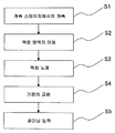
또한, 상기 서술한 제 1 ∼ 제 4 실시형태에 있어서, 종단 광학 소자 (11) 및 노즐 부재 (8) 에 대한 클리닝 동작은, 예를 들어 소정 매수의 기판 (P) 을 노광할 때마다, 혹은 로트마다, 혹은 소정 시간 간격마다 실행할 수 있다. 도 14 에, 제 1 ∼ 제 4 실시형태에 있어서의 클리닝 동작을 포함하는 액침 노광의 시퀀스의 일례를 도시한다. 제어 장치 (7) 의 제어에 의해 계측 테이블 (32) 이 노즐 부재 (8) 와 대향하는 위치에 위치 결정되고, 노즐 부재 (8) 와 계측 테이블 (32) 사이에 제 1 액침 공간 (LS1) 이 형성되고, 제 1 액체 (LQ) 를 통하여 계측 테이블 (32) 의 각종 계측기에 의한 계측이 실행된다 (S1). 이어서, 계측 테이블 (32) 이 노즐 부재 (8) 하방으로부터 멀어지면서 기판 테이블 (22) 이 노즐 부재 (8) 하방으로 이동함으로써, 액체 (LQ) 가 계측 테이블 (32) 로부터 기판 테이블 (22) 에 건내져, 제 1 액침 공간 (LS1) 이 기판 테이블 (22) 상의 기판 (P) 과 노즐 부재 (8) 및 투영 광학계 (PL) 사이에 형성된다 (S2). 제어 장치 (7) 는, 계측 테이블 (32) 에서의 계측 결과에 기초하여 기판 (P) 의 노광 조건을 조정하여, 기판 (P) 의 액침 노광을 실시한다 (S3). 액침 노광이 끝나면, 기판 테이블 (22) 은 소정의 기판 교환 위치로 이동하고, 그곳에서 기판의 교환이 이루어진다 (S4). 이 기판의 교환 후 혹은 기판의 교환과 병행하여, 전술한 클리닝 동작이 실행된다 (S5). 예를 들어, 제 1 실시형태와 같이, 클리닝 동작이 기판 테이블 (22) 상에서 행해지는 경우에는, 소정 매수의 기판 노광이 종료된 후에, 기 판의 교환 단계 (S4) 후에 클리닝 동작을 실시할 수 있다. 제 3 실시형태와 같이, 클리닝 동작이 계측 테이블 (32) 상에서 행해지는 경우에는, 소정 매수의 기판 노광이 종료된 후에, 기판 스테이지 (22) 에서의 기판의 교환 단계 (S4) 와 병행하거나 혹은 그 전후로 클리닝 동작을 실시할 수 있다.In addition, in 1st-4th embodiment mentioned above, the cleaning operation | movement with respect to the terminal
상기 실시형태에 있어서, 종단 광학 소자 (11) 및 노즐 부재 (8) 의 적어도 일방의 오염 상태를 검출할 수 있는 검출 장치를 설치하고, 그 검출 장치의 검출 결과에 기초하여, 종단 광학 소자 (11) 및 노즐 부재 (8) 의 적어도 일방이 오염되어 있는 것으로 판단했을 때에, 클리닝 동작을 실행하도록 해도 된다. 예를 들어, 계측 테이블 (32) 에 광량 검출기를 배치하고, 종단 광학 소자 (11) 의 하면 (11A) 으로부터 사출되는 노광광 (EL) 의 광량을, 계측 테이블 (32) 에 배치되어 있는 광량 검출기로 검출하고, 그 검출 결과에 기초하여, 클리닝 동작을 실행하는지 여부를 판단할 수 있다. 종단 광학 소자 (11) 의 하면 (11A) 이 오염되어 있는 상태와 오염되어 있지 않은 상태에서는, 광량 검출기에 조사되는 노광광 (EL) 의 광량이 변화될 가능성이 높다. 따라서, 광량 검출기의 검출 결과에 기초하여, 종단 광학 소자 (11) 의 하면 (11A) 의 오염 상태를 구할 수 있다.In the said embodiment, the detection apparatus which can detect the contamination state of at least one of the terminal
또한, 마스크 (M) 및 투영 광학계 (PL) 를 통한 노광광 (EL) 으로 기판 (P) 을 노광하고, 현상 처리를 실시한 후, 그 기판 (P) 상에 형성된 패턴의 형상을 소정의 계측 장치로 계측하고, 그 계측 결과에 기초하여, 클리닝 동작을 실행하는지 여부를 판단하도록 해도 된다. 예를 들어, 패턴 형상의 계측 결과에 기초하여, 패턴의 결함이 허용 범위가 아닌 것으로 판단한 경우, 종단 광학 소자 (11) 의 하 면 (11A) 의 오염 상태도 허용 범위가 아닌 것으로 판단하여, 클리닝 동작을 실행한다.Moreover, after exposing the board | substrate P with the exposure light EL through the mask M and the projection optical system PL, and developing-processing, the shape of the pattern formed on the board | substrate P is predetermined measurement device. It is also possible to determine whether or not to perform a cleaning operation based on the measurement result. For example, based on the measurement result of a pattern shape, when it determines with the defect of a pattern not being an allowable range, it is judged that the contamination state of the
또한, 종단 광학 소자 (11) 의 하면 (11A), 노즐 부재 (8) 의 하면 (8A) 등의 화상 (광학 이미지) 정보를 취득할 수 있는 촬상 장치 (카메라) 를 설치하고, 그 촬상 장치의 촬상 결과에 기초하여, 종단 광학 소자 (11) 의 하면 (11A), 노즐 부재 (8) 의 하면 (8A) 등이 오염되어 있는지 여부를 판단하고, 그 판단 결과에 기초하여, 클리닝 동작을 실행하는지 여부를 판단하도록 해도 된다.In addition, an imaging device (camera) capable of acquiring image (optical image) information such as the
상기 실시형태에 있어서, 초음파 발생 장치 (10(C)) 에 의해 진동 부재 (150(C)) 를 통하여 발생하는 초음파를 검출하는 검출기를 설치해도 된다. 예를 들어, PZT 로 이루어지는 초음파 수신 소자를, 노즐 부재 (8) 나 계측 테이블 (32) 에 매설 등으로 설치할 수 있다. 이렇게 함으로써, 초음파가 제 2 액침 공간 (LS2) 에 유효하게 전파되고 있는 것을 확인할 수 있고, 또한 초음파의 주파수나 제 2 액체 (LC) 의 공급 및 회수 (유량, 매질, 온도 등) 가 초음파의 전파에 미치는 영향을 관측할 수 있다. 이들의 관측 결과에 기초하여 초음파 발생 장치 (10(C)) 의 압전 소자 구동 회로를 최선으로 설정할 수 있다.In the said embodiment, you may provide the detector which detects the ultrasonic wave which generate | occur | produces through the vibration member 150 (C) by the ultrasonic wave generator 10 (C). For example, the ultrasonic receiving element made of PZT can be installed in the
또한, 상기 서술한 각 실시형태에 있어서는, 진동 부재 (150(150C)) 의 상면 (151(151C)), 기판 테이블 (22) 의 상면 (24), 계측 테이블 (32) 의 상면 (34) 등은, 제 1 액체 (LQ) 및 제 2 액체 (LC) 의 양방에 대해 발액성을 가지고 있는데, 어느 일방, 예를 들어 노광용의 제 1 액체 (LQ) 에 대해서만 발액성이어도 된다.In addition, in each embodiment mentioned above, the upper surface 151 (151C) of the vibration member 150 (150C), the
또한, 상기 서술한 각 실시형태 (및 다양한 개변) 에서 설명한 클리닝 동작, 클리닝 기구를 적절히 조합하여 사용할 수 있는 것은 말할 필요도 없다. 상기 실시형태에서는, 클리닝용 액체 (LC) 가 진동 부재 (150(C)) 상에 존재할 때에 초음파 발생 장치 (10) 로부터 발생하는 초음파를 사용하여 종단 광학 소자 (11) 의 하면 (11A) 이나 노즐 부재 (8) 의 하면 (8A) 등의 액체 (LQ) 와 접촉하는 부위를 세정했으나, 클리닝용 액체 (LC) 가 진동 부재 (150(C)) 상뿐만 아니라, 기판 테이블 (22) 및/또는 계측 테이블 (32) 상의 진동 부재 (150(C)) 와는 상이한 부위 (위치) 에 존재함으로써, 그들의 부위를 세정할 수도 있다. 이 때, 클리닝용 액체 (LC) 가 기판 테이블 (22) 또는 계측 테이블 (32) 과 노즐 부재 (8) 의 하면 (8A) 사이에 존재할 때에, 기판 테이블 (22) 또는 계측 테이블 (32) 을 노즐 부재 (8) 에 대해 이동시켜도 된다.It goes without saying that the cleaning operations and cleaning mechanisms described in the above-described embodiments (and various modifications) can be appropriately used in combination. In the above embodiment, the
또한, 상기 서술한 각 실시형태의 노광용 액체 (LQ) 는 물이지만, 물 이외의 액체이어도 되고, 예를 들어 노광광 (EL) 의 광원이 F2 레이저인 경우, 이 F2 레이저광은 물을 투과하지 않으므로, 액체 (LQ) 로는 F2 레이저광이 투과할 수 있는, 예를 들어 과불화 폴리에테르 (PFPE) 나 불소계 오일 등의 불소계 유체이어도 된다. 또한, 액체 (LQ) 로서는, 그 외에도, 노광광 (EL) 에 대한 투과성이 있어 가능한 한 굴절률이 높고, 투영 광학계 (PL) 나 기판 (P) 표면에 도포되어 있는 포토레지스트에 대해 안정적인 것 (예를 들어 시더유) 을 사용할 수도 있다. 또한, 액체 (LQ) 로서는, 굴절률이 1.6 ∼ 1.8 정도인 것을 사용해도 된다. 여기서, 순수보다도 굴절률이 높은 (예를 들어 1.5 이상) 액체 (1) 로는, 예를 들어 굴절률 이 약 1.50 인 이소프로판올, 굴절률이 약 1.61 인 글리세롤 (글리세린) 등의 C-H 결합 혹은 O-H 결합을 갖는 소정 액체, 헥산, 헵탄, 데칸 등의 소정 액체 (유기 용제), 혹은 굴절률이 약 1.60 인 데칼린 (Decalin : Decahydronaphthalene) 등을 들 수 있다. 또한, 액체 (1) 는, 이들 액체 중 임의의 2 종류 이상의 액체를 혼합한 것이어도 되고, 순수에 이들 액체 중 적어도 하나를 첨가 (혼합) 한 것이어도 된다. 또한 액체 (1) 는, 순수에 H+, Cs+, K+, Cl-, SO4 2-, PO4 2- 등의 염기 또는 산을 첨가 (혼합) 한 것이어도 되고, 순수에 Al 산화물 등의 미립자를 첨가 (혼합) 한 것이어도 된다. 또한, 액체 (1) 로는, 광의 흡수 계수가 작고, 온도 의존성이 적으며, 투영 광학계 (PL) 및/또는 기판 (P) 의 표면에 도포되어 있는 감광재 (또는 탑코트막 혹은 반사 방지막 등) 에 대해 안정적인 것이 바람직하다. 또한, 투영 광학계 (PL) 의 광학 소자 (최종 광학 소자 (11) 등) 를, 석영, 형석 이외에, 불화 바륨, 불화 스트론튬, 불화 리튬, 및 불화 나트륨 등의 불화 화합물의 단결정 재료로 형성된 것을 사용해도 된다. 또한 석영 및 형석보다도 굴절률이 높은 (예를 들어 1.6 이상) 재료로, 액체 (LQ) 와 접촉하는 투영 광학계 (PL) 의 광학 소자 (최종 광학 소자 (FL) 등) 를 형성해도 된다. 굴절률이 1.6 이상인 재료로는, 예를 들어 국제 공개 제2005/059617호 팜플렛에 개시되는 사파이어, 이산화 게르마늄 등, 혹은 국제 공개 제2005/059618호 팜플렛에 개시되는 염화 칼륨 (굴절률은 약 1.75) 등을 사용할 수 있다. 액체 (LQ) 로서 각종 유체, 예를 들어 초임계 유체를 사용할 수도 있다.Further, although the above-described exposure, the liquid (LQ) of the embodiments described is water, it may be a liquid other than water, for example, the exposure light (EL) of when the light source is F 2 laser is, the F 2 laser light is water does not pass through, the liquid (LQ) roneun with a F 2 laser beam can be transmitted through, for example, may be a fluorine-based fluid such as perfluorinated polyether (PFPE) or fluorine based oil. In addition, as the liquid LQ, in addition, it is transparent to the exposure light EL, and the refractive index is as high as possible and stable to the photoresist applied to the projection optical system PL or the substrate P surface (Example Cedar oil) can also be used. As the liquid LQ, a refractive index of about 1.6 to 1.8 may be used. Here, as the
또한, 상기 서술한 각 실시형태에 있어서는, 투영 광학계의 종단 광학 소자의 사출측 (이미지면측) 의 광로 공간을 액체로 채우고 있는데, 국제 공개 제2004/019128호 팜플렛 (대응 미국 특허 공개 제2005/0248856호) 에 개시되어 있는 바와 같이, 종단 광학 소자의 광입사측 (물체면측) 의 광로 공간도 액체로 채우는 투영 광학계를 채용할 수도 있다.Moreover, in each embodiment mentioned above, although the optical path space of the exit side (image surface side) of the terminal optical element of a projection optical system is filled with liquid, International Publication No. 2004/019128 pamphlet (corresponding US patent publication 2005/0248856). As disclosed in (A), a projection optical system may also be employed in which the optical path space on the light incident side (object surface side) of the terminal optical element is also filled with liquid.
또한, 상기 서술한 각 실시형태에 있어서는, 투영 광학계 (PL) 와 기판 (P) 사이에 국소적으로 액체를 채우는 노광 장치를 채용하고 있는데, 미국 특허 제5,825,043호 등에 개시되어 있는 바와 같은, 노광 대상의 기판의 표면 전체가 액체 중에 잠겨 있는 상태에서 노광을 실시하는 액침 노광 장치를 채용할 수 있다.Moreover, in each embodiment mentioned above, although the exposure apparatus which fills a liquid locally between the projection optical system PL and the board | substrate P is employ | adopted, the exposure object as disclosed in US Patent 5,825,043 etc. The liquid immersion exposure apparatus which performs exposure in the state in which the whole surface of the board | substrate of the board | substrate is submerged in the liquid can be employ | adopted.
또한, 상기 서술한 각 실시형태의 기판 (P) 으로는, 반도체 디바이스 제조용 반도체 웨이퍼뿐만 아니라, 디스플레이 디바이스용 유리 기판, 박막 자기 헤드용 세라믹 웨이퍼, 혹은 노광 장치에서 사용되는 마스크 또는 레티클의 원판 (합성 석영, 실리콘 웨이퍼) 등이 적용된다.In addition, as the board | substrate P of each embodiment mentioned above, not only the semiconductor wafer for semiconductor device manufacture, but also the glass substrate for display devices, the ceramic wafer for thin film magnetic heads, or the original plate of a mask or reticle used by an exposure apparatus (synthesis | combination) Quartz, silicon wafers) and the like.
노광 장치 (EX) 로는, 마스크 (M) 와 기판 (P) 을 동기 이동시켜 마스크 (M) 의 패턴을 주사 노광하는 스텝·앤드·스캔 방식의 주사형 노광 장치 (스캐닝 스테퍼) 외에, 마스크 (M) 와 기판 (P) 을 정지 (靜止) 시킨 상태에서 마스크 (M) 의 패턴을 일괄 노광하여, 기판 (P) 을 순차적으로 스텝 이동시키는 스텝·앤드·리피트 방식의 투영 노광 장치 (스테퍼) 를 채용할 수 있다.As the exposure apparatus EX, in addition to the scanning exposure apparatus (scanning stepper) of the step-and-scan method which scan-exposures the pattern of the mask M by moving the mask M and the board | substrate P synchronously, the mask M ) And a step-and-repeat projection exposure apparatus (stepper) that collectively exposes the pattern of the mask M and sequentially moves the substrate P in a state where the substrate P is stopped. can do.
또한, 노광 장치 (EX) 로서 스텝·앤드·리피트 방식의 노광에 있어서, 제 1 패턴과 기판 (P) 을 거의 정지시킨 상태에서, 투영 광학계를 사용하여 제 1 패턴의 축소 이미지를 기판 (P) 상에 전사시킨 후, 제 2 패턴과 기판 (P) 을 거의 정지시킨 상태에서, 투영 광학계를 사용하여 제 2 패턴의 축소 이미지를 제 1 패턴과 부분적으로 중첩하여 기판 (P) 상에 일괄 노광하는 스티치 방식의 일괄 노광 장치를 채용해도 된다. 또한, 스티치 방식의 노광 장치로는, 기판 (P) 상에서 적어도 2 개의 패턴을 부분적으로 중첩하여 전사하고, 기판 (P) 을 순차적으로 이동시키는 스텝·앤드·스티치 방식의 노광 장치를 채용할 수도 있다.In addition, in exposure of a step-and-repeat system as the exposure apparatus EX, in the state which stopped the 1st pattern and the board | substrate P substantially, the reduced image of the 1st pattern was used for the board | substrate P using the projection optical system. After transferring onto the image, in a state where the second pattern and the substrate P are substantially stopped, the reduced image of the second pattern is partially overlapped with the first pattern using the projection optical system to collectively expose the substrate P on the substrate P. You may employ | adopt the batch exposure apparatus of the stitch system. Moreover, as a stitch type exposure apparatus, you may employ | adopt the exposure apparatus of the step-and-stitch system which partially transfers at least two patterns on the board | substrate P, transfers them, and moves the board | substrate P sequentially. .
또한, 노광 장치 (EX) 로서 예를 들어 미국 특허 제6,611,316호에 개시되어 있는 바와 같이, 2 개의 마스크의 패턴을, 투영 광학계를 통하여 기판 상에서 합성하여, 1 회의 주사 노광에 의해 기판 상의 하나의 쇼트 영역을 거의 동시에 이중 노광하는 노광 장치 등을 채용할 수 있다. 또한, 노광 장치 (EX) 로서 프록시미티 방식의 노광 장치, 미러 프로젝션·얼라이너 등을 채용할 수 있다.Further, as disclosed in, for example, US Pat. No. 6,611,316 as the exposure apparatus EX, a pattern of two masks is synthesized on a substrate through a projection optical system, and one shot on the substrate by one scanning exposure. An exposure apparatus etc. which double-expose the area at about the same time can be employed. As the exposure apparatus EX, an exposure apparatus of a proximity system, a mirror projection aligner, or the like can be adopted.
또한, 노광 장치 (EX) 로서 미국 특허 6,341,007호, 미국 특허 6,400,441호, 미국 특허 6,549,269호, 및 미국 특허 6,590,634호, 미국 특허 6,208,407호, 미국 특허 6,262,796호 등에 개시되어 있는 바와 같은 복수의 기판 스테이지를 구비한 트윈 스테이지형의 노광 장치를 채용할 수도 있다. 또한, 복수의 기판 스테이지와 계측 스테이지를 구비한 노광 장치를 채용할 수 있다. 이들의 복수의 스테이지를 구비하는 노광 장치에서는, 어느 스테이지에 진동 부재 및 진동 발생 장치가 설치되어 있어도 된다. 또한, 상기 실시형태에서는, 기판 테이블 및/또는 계측 테이블에 진동 부재 (150(C)) 및 초음파 발생 장치 (10(C)) 를 설치하므로, 그들의 테이블과는 별도의 가동 테이블, 예를 들어 진동 부재 및 초음파 발생 장치 가 설치된 클리닝 전용 테이블을 설치해도 된다.Further, as the exposure apparatus EX, there is provided a plurality of substrate stages as disclosed in US Patent 6,341,007, US Patent 6,400,441, US Patent 6,549,269, and US Patent 6,590,634, US Patent 6,208,407, US Patent 6,262,796, and the like. One twin stage type exposure apparatus can also be used. Moreover, the exposure apparatus provided with the some board | substrate stage and the measurement stage can be employ | adopted. In the exposure apparatus provided with these multiple stages, the vibration member and the vibration generating apparatus may be provided in any stage. In addition, in the said embodiment, since the vibration member 150 (C) and the ultrasonic wave generator 10 (C) are provided in a board | substrate table and / or a measurement table, the movable table separate from those tables, for example, a vibration A cleaning dedicated table provided with the member and the ultrasonic generator may be provided.
노광 장치 (EX) 의 종류로는, 기판 (P) 에 반도체 소자 패턴을 노광하는 반도체 소자 제조용 노광 장치에 한정되지 않고, 액정 표시 소자 제조용 또는 디스플레이 제조용 노광 장치, 박막 자기 헤드, 촬상 소자 (CCD), 마이크로 머신, MEMS, DNA 칩, 혹은 레티클 또는 마스크 등을 제조하기 위한 노광 장치 등에도 널리 적용할 수 있다.As the kind of exposure apparatus EX, it is not limited to the exposure apparatus for semiconductor element manufacture which exposes a semiconductor element pattern to the board | substrate P, The exposure apparatus for liquid crystal display element manufacture or display manufacture, a thin film magnetic head, an imaging element (CCD) It can also be widely applied to an exposure apparatus for manufacturing a micromachine, a MEMS, a DNA chip, a reticle or a mask, or the like.
또한, 상기 서술한 각 실시형태에 있어서는, 레이저 간섭계를 포함하는 간섭계 시스템을 사용하여 마스크 스테이지, 기판 스테이지, 및 계측 스테이지의 각 위치 정보를 계측하는 것으로 했으나, 이것에 한정되지 않고, 예를 들어 각 스테이지에 설치되는 스케일 (회절 격자) 을 검출하는 인코더 시스템을 사용해도 된다. 이 경우, 간섭계 시스템과 인코더 시스템의 양방을 구비하는 하이브리드 시스템으로 하여, 간섭계 시스템의 계측 결과를 이용하여 인코더 시스템의 계측 결과의 교정 (캘리브레이션) 을 실시하는 것이 바람직하다. 또한, 간섭계 시스템과 인코더 시스템을 전환하여 사용하거나, 혹은 그 양방을 사용하여 스테이지의 위치 제어를 실시하도록 해도 된다.In addition, in each embodiment mentioned above, although each positional information of the mask stage, the board | substrate stage, and the measurement stage was measured using the interferometer system containing a laser interferometer, it is not limited to this, for example, You may use the encoder system which detects the scale (diffraction grating) installed in a stage. In this case, as a hybrid system having both an interferometer system and an encoder system, it is preferable to perform calibration (calibration) of the measurement results of the encoder system using the measurement results of the interferometer system. In addition, you may switch between an interferometer system and an encoder system, or may use both to perform position control of a stage.
또한, 상기 서술한 각 실시형태에서는, 노광광 (EL) 으로서 ArF 엑시머 레이저광을 발생하는 광원 장치로서, ArF 엑시머 레이저를 사용해도 되는데, 예를 들어 미국 특허 7,023,610호에 개시되어 있는 바와 같이, DFB 반도체 레이저 또는 파이버 레이저 등의 고체 레이저 광원, 파이버 앰프 등을 갖는 광증폭부, 및 파장 변환부 등을 포함하고, 파장 193 ㎚ 의 펄스광을 출력하는 고조파 발생 장치를 사용해 도 된다. 또한, 상기 실시형태에서는, 전술한 각 조명 영역과, 투영 영역이 각각 직사각형 형상인 것으로 했는데, 다른 형상, 예를 들어 원호 형상 등이어도 된다.In each of the above-described embodiments, an ArF excimer laser may be used as the light source device for generating ArF excimer laser light as the exposure light EL. For example, as disclosed in US Pat. No. 7,023,610, DFB A harmonic generator that outputs pulsed light having a wavelength of 193 nm, including a solid laser light source such as a semiconductor laser or a fiber laser, an optical amplifier having a fiber amplifier, and the like, a wavelength converter, or the like may be used. In addition, in the said embodiment, although each illumination area and projection area | region mentioned above were each rectangular shape, other shapes, for example, arc shape etc. may be sufficient.
또한, 상기 서술한 실시형태에 있어서는, 광투과성의 기판 상에 소정 차광 패턴 (또는 위상 패턴·감광 패턴) 을 형성한 광투과형 마스크를 사용했으나, 이 마스크 대신에, 예를 들어 미국 특허 제6,778,257호에 개시되어 있는 바와 같이, 노광해야 할 패턴의 전자 데이터에 기초하여 투과 패턴 또는 반사 패턴, 혹은 발광 패턴을 형성하는 가변 성형 마스크 (전자 마스크, 액티브 마스크, 혹은 이미지 제너레이터라고도 한다) 를 사용해도 된다. 가변 성형 마스크는, 예를 들어 비발광형 화상 표시 소자 (공간 광변조기) 의 일종인 DMD (Digital Micro-mirror Device) 등을 포함한다. 또한, 가변 성형 마스크로는, DMD 에 한정되는 것이 아니고, DMD 대신에, 이하에 설명하는 비발광형 화상 표시 소자를 사용해도 된다. 여기서, 비발광형 화상 표시 소자는, 소정 방향으로 진행되는 광의 진폭 (강도), 위상 혹은 편광 상태를 공간적으로 변조하는 소자이고, 투과형 공간 광변조기로는, 투과형 액정 표시 소자 (LCD : Liquid Crystal Display) 이외에, 일렉트로크로믹 디스플레이 (ECD) 등을 예로서 들 수 있다. 또한, 반사형 공간 광변조기로는, 상기 서술한 DMD 외에, 반사 미러 어레이, 반사형 액정 표시 소자, 전기 영동 디스플레이 (EPD : Electro Phonetic Display), 전자 페이퍼 (또는 전자 잉크), 광회절형 라이트 밸브 (Grating Light Valve) 등을 예로서 들 수 있다.In addition, in the above-mentioned embodiment, although the light transmissive mask which provided the predetermined light shielding pattern (or phase pattern and photosensitive pattern) was used on the light transmissive board | substrate, US Pat. No. 6,778,257 is used instead of this mask, for example. As disclosed in, a variable shaping mask (also referred to as an electronic mask, an active mask, or an image generator) that forms a transmission pattern, a reflection pattern, or a light emission pattern based on electronic data of a pattern to be exposed may be used. The variable shaping mask includes, for example, a DMD (Digital Micro-mirror Device), which is a kind of non-light-emitting image display element (spatial light modulator). In addition, as a variable shaping mask, it is not limited to DMD, Instead of DMD, you may use the non-emission type image display element demonstrated below. Here, the non-luminous image display element is an element that spatially modulates the amplitude (intensity), phase, or polarization state of light propagating in a predetermined direction, and as a transmissive spatial light modulator, a transmissive liquid crystal display element (LCD: Liquid Crystal Display) ), Electrochromic display (ECD) and the like can be given as examples. As the reflective spatial light modulator, in addition to the above-described DMD, a reflective mirror array, a reflective liquid crystal display element, an electrophoretic display (EPD), an electronic paper (or electronic ink), an optical diffraction type light valve (Grating Light Valve) etc. are mentioned as an example.
또한, 비발광형 화상 표시 소자를 구비하는 가변 성형 마스크 대신에, 자발 광형 화상 표시 소자를 포함하는 패턴 형성 장치를 구비하게 해도 된다. 이 경우, 조명 광학계는 불필요해진다. 여기서 자발광형 화상 표시 소자로는, 예를 들어 CRT (Cathode Ray Tube), 무기 EL 디스플레이, 유기 EL 디스플레이 (OLED : Organic Light Emitting Diode), LED 디스플레이, LD 디스플레이, 전계 방출 디스플레이 (FED : Field Emission Display), 플라스마 디스플레이 (PDP : Plasma Display Panel) 등을 들 수 있다. 또한, 패턴 형성 장치가 구비하는 자발광형 화상 표시 소자로서, 복수의 발광점을 갖는 고체 광원 칩, 칩을 복수개 어레이 형상으로 배열한 고체 광원칩 어레이, 또는 복수의 발광점을 1 장의 기판에 만들어 넣은 타입인 것 등을 사용하고, 그 고체 광원칩을 전기적으로 제어하여 패턴을 형성해도 된다. 또한, 고체 광원 소자는 무기, 유기를 불문한다.In addition, a pattern forming apparatus including a self-luminous type image display element may be provided instead of the variable molding mask including the non-luminous type image display element. In this case, the illumination optical system becomes unnecessary. As the self-luminous image display element, for example, CRT (Cathode Ray Tube), inorganic EL display, organic EL display (OLED: Organic Light Emitting Diode), LED display, LD display, field emission display (FED: Field Emission) Display, Plasma Display Panel (PDP) and the like. Further, as a self-luminous image display element included in a pattern forming apparatus, a solid light source chip having a plurality of light emitting points, a solid light source chip array in which a plurality of chips are arranged in an array shape, or a plurality of light emitting points are formed on a single substrate. The solid type light source chip may be electrically controlled, and the pattern may be formed by using the loaded type. In addition, a solid light source element is irrespective of inorganic and organic.
상기 서술한 각 실시형태에 있어서는, 투영 광학계 (PL) 를 구비한 노광 장치를 예로 들어 설명해 왔는데, 투영 광학계 (PL) 를 사용하지 않는 노광 장치 및 노광 방법으로 채용할 수 있다. 이와 같이 투영 광학계 (PL) 를 사용하지 않는 경우에도, 노광광은 렌즈 등의 광학 부재를 통하여 기판에 조사되고, 그러한 광학 부재와 기판 사이의 소정 공간에 액침 공간이 형성된다.In each embodiment mentioned above, although the exposure apparatus provided with the projection optical system PL was demonstrated as an example, it can be employ | adopted as the exposure apparatus and exposure method which do not use the projection optical system PL. Even when the projection optical system PL is not used in this manner, the exposure light is irradiated onto the substrate through an optical member such as a lens, and a liquid immersion space is formed in a predetermined space between the optical member and the substrate.
또한, 노광 장치 (EX) 로서 예를 들어 국제 공개 제2001/035168호 팜플렛에 개시되어 있는 바와 같이, 간섭 무늬를 기판 (P) 상에 형성함으로써, 기판 (P) 상에 라인·앤드·스페이스 패턴을 노광하는 노광 장치 (리소그래피 시스템) 를 채용할 수 있다. 또한, 본 발명은, 투영 광학계와 기판 사이의 액침 영역을 그 주위의 에어 커튼으로 유지하는 액침형의 노광 장치에도 적용할 수 있다.Moreover, as disclosed in the international publication 2001/035168 pamphlet as an exposure apparatus EX, for example, a line and space pattern is formed on the substrate P by forming an interference fringe on the substrate P. FIG. An exposure apparatus (lithography system) for exposing the light may be employed. Moreover, this invention is applicable also to the immersion type exposure apparatus which keeps the immersion area | region between a projection optical system and a board | substrate with the air curtain around it.
본원 실시형태의 노광 장치 (EX) 는, 본원 청구의 범위에 거론된 각 구성 요소를 포함하는 각종 서브 시스템을, 소정의 기계적 정밀도, 전기적 정밀도, 광학적 정밀도를 유지하도록, 조립함으로써 제조된다. 이들 각종 정밀도를 확보하기 위해서, 이 조립의 전후에는, 각종 광학계에 대해서는 광학적 정밀도를 달성하기 위한 조정, 각종 기계계에 대해서는 기계적 정밀도를 달성하기 위한 조정, 각종 전기계에 대해서는 전기적 정밀도를 달성하기 위한 조정이 이루어진다. 각종 서브 시스템으로부터 노광 장치에 대한 조립 공정은, 각종 서브 시스템 상호의, 기계적 접속, 전기 회로의 배선 접속, 기압 회로의 배관 접속 등이 포함된다. 이 각종 서브 시스템으로부터 노광 장치에 대한 조립 공정 전에, 각 서브 시스템 개개의 조립 공정이 있는 것은 말할 필요도 없다. 각종 서브 시스템의 노광 장치에 대한 조립 공정이 종료되면, 종합 조정이 이루어져, 노광 장치 전체로서의 각종 정밀도가 확보된다. 또한, 노광 장치의 제조는 온도 및 클린도 등이 관리된 클린룸에서 실시하는 것이 바람직하다.The exposure apparatus EX of this embodiment is manufactured by assembling various subsystems including each component mentioned in the claim of this application so as to maintain predetermined mechanical precision, electrical precision, and optical precision. In order to secure these various accuracy, before and after this assembly, adjustment for achieving optical precision for various optical systems, adjustment for achieving mechanical precision for various mechanical systems, and electrical precision for various electric systems Adjustment is made. The assembling process from the various subsystems to the exposure apparatus includes a mechanical connection, a wiring connection of an electric circuit, a pipe connection of an air pressure circuit, and the like among various subsystems. It goes without saying that there is an assembling process for each of the subsystems before the assembling process for the exposure apparatus from these various subsystems. When the assembly process with respect to the exposure apparatus of various subsystems is complete | finished, comprehensive adjustment is made and various precision as the whole exposure apparatus is ensured. In addition, it is preferable to perform manufacture of exposure apparatus in the clean room where temperature, a clean degree, etc. were managed.
반도체 디바이스 등의 마이크로 디바이스는, 도 15 에 도시하는 바와 같이, 마이크로 디바이스의 기능·성능 설계를 실시하는 단계 (201), 이 설계 단계에 기초한 마스크 (레티클) 를 제작하는 단계 (202), 디바이스의 기재인 기판을 제조하는 단계 (203), 전술한 실시형태에 따라, 마스크로부터의 노광광으로 기판을 노광하는 것, 및 노광된 기판을 현상하는 것을 포함하는 기판 처리 단계 (204), 디바이스 조립 단계 (다이싱 공정, 본딩 공정, 패키지 공정 등의 가공 프로세스를 포함) (205), 검사 단계 (206) 등을 거쳐 제조된다. 상기 서술한 각 실시형태에서 설 명한 노광 장치 (EX) 에 있어서의 클리닝 방법은, 기판 처리 단계 (204) 에 포함되고, 그 클리닝 방법으로 클리닝된 노광 장치 (EX) 를 사용하여, 기판 (P) 을 노광하는 것이 실시된다.As shown in FIG. 15, a microdevice such as a semiconductor device includes a
또한, 상기 서술한 바와 같이 본 발명의 실시형태를 설명했는데, 본 발명은 상기 서술한 모든 구성 요소를 적절히 조합하여 이용할 수 있고, 또한 일부의 구성 요소를 이용하지 않는 경우도 있다. 예를 들어, 실시형태 4 및 그 변형형태에서는, 진동 부재의 표면이 액침 액체 (LQ) 및/또는 클리닝용 액체 (LC) 에 대해 발액성이 아니어도 된다. 또한, 상기 서술한 각 실시형태에 있어서, 제 1 및 제 2 액체 공급 장치 (86, 96) 그리고 액체 회수 장치 (89) 가 노광 장치에 설치되어 있을 필요는 없고, 예를 들어 노광 장치가 설치되는 공장 등의 설비를 대용해도 된다. 또한, 액침 노광에 필요한 구조는, 상기 서술한 구조에 한정되지 않고, 예를 들어 유럽 특허 공개 공보 제1420298호, 국제 공개 제2004/055803호 팜플렛, 국제 공개 제2004/057590호 팜플렛, 국제 공개 제2005/029559호 팜플렛 (대응 미국 특허 공개 제2006/0231206호), 국제 공개 제2004/086468호 팜플렛 (대응 미국 특허 공개 제2005/0280791호), 일본 공개특허공보 2004-289126호 (대응 미국 특허 제6,952,253호) 등에 기재되어 있는 것을 사용할 수 있다. 액침 노광 장치의 액침 기구 및 그 부속 기기에 대해, 지정국 또는 선택국의 법령이 허락하는 범위에서 상기의 미국 특허 또는 미국 특허 공개 등의 개시를 원용하여 본문 기재의 일부로 한다.Moreover, although embodiment of this invention was described as mentioned above, this invention can use all the above-mentioned components suitably in combination, and may not use some components. For example, in
또한, 상기 서술한 각 실시형태 및 변형예에서 인용한 노광 장치 등에 관한 모든 공개 공보 및 미국 특허의 개시를 원용하여 본문 기재의 일부로 한다.In addition, all the publications concerning the exposure apparatus etc. which were quoted by each above-mentioned embodiment and modified example, and the indication of a US patent are used as a part of description.
산업상이용가능성Industrial availability
본 발명의 노광 방법 및 디바이스 제조 방법에 의하면, 클리닝용 액체를 사용하여 노광 장치의 액체와 접하는 부위가 유효하게 세정되기 때문에, 제조되는 디바이스의 수율이 향상된다. 그러므로, 본 발명은, 반도체 산업을 포함하는 정밀 기기 산업의 국제적인 발전에 현저하게 공헌할 것이다.According to the exposure method and the device manufacturing method of this invention, since the site | part which contacts the liquid of an exposure apparatus using the cleaning liquid is effectively wash | cleaned, the yield of the device manufactured is improved. Therefore, the present invention will significantly contribute to the international development of the precision instrument industry including the semiconductor industry.
Claims (60)
Applications Claiming Priority (4)
| Application Number | Priority Date | Filing Date | Title |
|---|---|---|---|
| JP2007140474 | 2007-05-28 | ||
| JPJP-P-2007-140474 | 2007-05-28 | ||
| JPJP-P-2007-177217 | 2007-07-05 | ||
| JP2007177217 | 2007-07-05 |
Publications (1)
| Publication Number | Publication Date |
|---|---|
| KR20100031694A true KR20100031694A (en) | 2010-03-24 |
Family
ID=40075059
Family Applications (1)
| Application Number | Title | Priority Date | Filing Date |
|---|---|---|---|
| KR1020097027052A KR20100031694A (en) | 2007-05-28 | 2008-05-27 | Exposure apparatus, device manufacturing method, cleaning device, cleaning method and exposure method |
Country Status (5)
| Country | Link |
|---|---|
| US (2) | US8189168B2 (en) |
| JP (1) | JP2009033111A (en) |
| KR (1) | KR20100031694A (en) |
| TW (1) | TW200903589A (en) |
| WO (1) | WO2008146819A1 (en) |
Cited By (1)
| Publication number | Priority date | Publication date | Assignee | Title |
|---|---|---|---|---|
| KR101245659B1 (en) * | 2008-04-24 | 2013-03-20 | 에이에스엠엘 네델란즈 비.브이. | Lithographic apparatus and a method of operating the apparatus |
Families Citing this family (13)
| Publication number | Priority date | Publication date | Assignee | Title |
|---|---|---|---|---|
| EP2131242A1 (en) * | 2008-06-02 | 2009-12-09 | ASML Netherlands B.V. | Substrate table, lithographic apparatus and device manufacturing method |
| NL2004540A (en) | 2009-05-14 | 2010-11-18 | Asml Netherlands Bv | Lithographic apparatus and a method of operating the apparatus. |
| WO2011055860A1 (en) * | 2009-11-09 | 2011-05-12 | Nikon Corporation | Exposure apparatus, exposure method, exposure apparatus maintenance method, exposure apparatus adjustment method and device manufacturing method |
| NL2005610A (en) * | 2009-12-02 | 2011-06-06 | Asml Netherlands Bv | Lithographic apparatus and surface cleaning method. |
| US20120019804A1 (en) | 2010-07-23 | 2012-01-26 | Nikon Corporation | Cleaning method, cleaning apparatus, device fabricating method, program, and storage medium |
| US20120019802A1 (en) | 2010-07-23 | 2012-01-26 | Nikon Corporation | Cleaning method, immersion exposure apparatus, device fabricating method, program, and storage medium |
| US20120019803A1 (en) | 2010-07-23 | 2012-01-26 | Nikon Corporation | Cleaning method, liquid immersion member, immersion exposure apparatus, device fabricating method, program, and storage medium |
| US9632426B2 (en) * | 2011-01-18 | 2017-04-25 | Taiwan Semiconductor Manufacturing Company, Ltd. | In-situ immersion hood cleaning |
| EP2880721B1 (en) * | 2012-07-30 | 2020-12-23 | Technion Research & Development Foundation Ltd. | Energy conversion system |
| JP7411641B2 (en) * | 2018-09-12 | 2024-01-11 | ラム リサーチ コーポレーション | Particle measurement method and particle measurement device |
| WO2020064265A1 (en) | 2018-09-24 | 2020-04-02 | Asml Netherlands B.V. | A process tool and an inspection method |
| CN109622545B (en) * | 2019-01-11 | 2024-06-04 | 夏绎 | Structure for maintaining cleaning water between ultrasonic wave emitting surface and cleaning object surface |
| US11032941B2 (en) * | 2019-03-28 | 2021-06-08 | Intel Corporation | Modular thermal energy management designs for data center computing |
Family Cites Families (67)
| Publication number | Priority date | Publication date | Assignee | Title |
|---|---|---|---|---|
| JPS57117238A (en) | 1981-01-14 | 1982-07-21 | Nippon Kogaku Kk <Nikon> | Exposing and baking device for manufacturing integrated circuit with illuminometer |
| JPH06124873A (en) | 1992-10-09 | 1994-05-06 | Canon Inc | Liquid-soaking type projection exposure apparatus |
| JP2753930B2 (en) | 1992-11-27 | 1998-05-20 | キヤノン株式会社 | Immersion type projection exposure equipment |
| US5825043A (en) | 1996-10-07 | 1998-10-20 | Nikon Precision Inc. | Focusing and tilting adjustment system for lithography aligner, manufacturing apparatus or inspection apparatus |
| IL130137A (en) | 1996-11-28 | 2003-07-06 | Nikon Corp | Exposure apparatus and an exposure method |
| JP3626504B2 (en) | 1997-03-10 | 2005-03-09 | アーエスエム リソグラフィ ベスローテン フェンノートシャップ | Positioning device having two article holders |
| JP3747566B2 (en) | 1997-04-23 | 2006-02-22 | 株式会社ニコン | Immersion exposure equipment |
| JPH1116816A (en) | 1997-06-25 | 1999-01-22 | Nikon Corp | Projection aligner, method for exposure with the device, and method for manufacturing circuit device using the device |
| AU1175799A (en) | 1997-11-21 | 1999-06-15 | Nikon Corporation | Projection aligner and projection exposure method |
| JPH11162831A (en) * | 1997-11-21 | 1999-06-18 | Nikon Corp | Projection aligner and projection aligning method |
| JPH11176727A (en) | 1997-12-11 | 1999-07-02 | Nikon Corp | Projection aligner |
| US6897963B1 (en) | 1997-12-18 | 2005-05-24 | Nikon Corporation | Stage device and exposure apparatus |
| US6208407B1 (en) | 1997-12-22 | 2001-03-27 | Asm Lithography B.V. | Method and apparatus for repetitively projecting a mask pattern on a substrate, using a time-saving height measurement |
| EP1063742A4 (en) | 1998-03-11 | 2005-04-20 | Nikon Corp | Ultraviolet laser apparatus and exposure apparatus comprising the ultraviolet laser apparatus |
| WO1999049504A1 (en) | 1998-03-26 | 1999-09-30 | Nikon Corporation | Projection exposure method and system |
| JPH11307430A (en) * | 1998-04-23 | 1999-11-05 | Canon Inc | Aligner, manufacture of device, and drive |
| JP4505989B2 (en) | 1998-05-19 | 2010-07-21 | 株式会社ニコン | Aberration measurement apparatus, measurement method, projection exposure apparatus including the apparatus, device manufacturing method using the method, and exposure method |
| WO2001035168A1 (en) | 1999-11-10 | 2001-05-17 | Massachusetts Institute Of Technology | Interference lithography utilizing phase-locked scanning beams |
| US20020041377A1 (en) | 2000-04-25 | 2002-04-11 | Nikon Corporation | Aerial image measurement method and unit, optical properties measurement method and unit, adjustment method of projection optical system, exposure method and apparatus, making method of exposure apparatus, and device manufacturing method |
| US6611316B2 (en) | 2001-02-27 | 2003-08-26 | Asml Holding N.V. | Method and system for dual reticle image exposure |
| TW550635B (en) * | 2001-03-09 | 2003-09-01 | Toshiba Corp | Manufacturing system of electronic devices |
| TW529172B (en) | 2001-07-24 | 2003-04-21 | Asml Netherlands Bv | Imaging apparatus |
| CN100462844C (en) | 2002-08-23 | 2009-02-18 | 株式会社尼康 | Projection optical system and method for photolithography and exposure apparatus and method using same |
| CN100568101C (en) | 2002-11-12 | 2009-12-09 | Asml荷兰有限公司 | Lithographic equipment and device making method |
| JP3977324B2 (en) | 2002-11-12 | 2007-09-19 | エーエスエムエル ネザーランズ ビー.ブイ. | Lithographic apparatus |
| US7110081B2 (en) * | 2002-11-12 | 2006-09-19 | Asml Netherlands B.V. | Lithographic apparatus and device manufacturing method |
| CN101382738B (en) | 2002-11-12 | 2011-01-12 | Asml荷兰有限公司 | Lithographic projection apparatus |
| EP2495613B1 (en) | 2002-11-12 | 2013-07-31 | ASML Netherlands B.V. | Lithographic apparatus |
| EP1429188B1 (en) | 2002-11-12 | 2013-06-19 | ASML Netherlands B.V. | Lithographic projection apparatus |
| CN1723541B (en) * | 2002-12-10 | 2010-06-02 | 株式会社尼康 | Exposure apparatus and method for producing device |
| ATE424026T1 (en) | 2002-12-13 | 2009-03-15 | Koninkl Philips Electronics Nv | LIQUID REMOVAL IN A METHOD AND DEVICE FOR RADIATION OF STAINS ON A LAYER |
| ATE335272T1 (en) | 2002-12-19 | 2006-08-15 | Koninkl Philips Electronics Nv | METHOD AND ARRANGEMENT FOR IRRADIATION OF A LAYER USING A LIGHT POINT |
| WO2004086468A1 (en) | 2003-02-26 | 2004-10-07 | Nikon Corporation | Exposure apparatus and method, and method of producing apparatus |
| ATE449982T1 (en) * | 2003-04-11 | 2009-12-15 | Nikon Corp | CLEANING PROCESS FOR OPTICS IN IMMERSION LITHOGRAPHY |
| SG2012031217A (en) | 2003-04-11 | 2015-09-29 | Nippon Kogaku Kk | Apparatus having an immersion fluid system configured to maintain immersion fluid in a gap adjacent an optical assembly |
| TWI616932B (en) * | 2003-05-23 | 2018-03-01 | Nikon Corp | Exposure device and component manufacturing method |
| US7684008B2 (en) | 2003-06-11 | 2010-03-23 | Asml Netherlands B.V. | Lithographic apparatus and device manufacturing method |
| US7317504B2 (en) * | 2004-04-08 | 2008-01-08 | Asml Netherlands B.V. | Lithographic apparatus and device manufacturing method |
| JP3862678B2 (en) * | 2003-06-27 | 2006-12-27 | キヤノン株式会社 | Exposure apparatus and device manufacturing method |
| EP2466382B1 (en) | 2003-07-08 | 2014-11-26 | Nikon Corporation | Wafer table for immersion lithography |
| JP4444920B2 (en) | 2003-09-19 | 2010-03-31 | 株式会社ニコン | Exposure apparatus and device manufacturing method |
| KR101238134B1 (en) | 2003-09-26 | 2013-02-28 | 가부시키가이샤 니콘 | Projection exposure apparatus, cleaning and maintenance methods of projection exposure apparatus, and method of producing device |
| EP1699072B1 (en) | 2003-12-03 | 2016-08-31 | Nikon Corporation | Exposure apparatus and exposure method |
| WO2005059617A2 (en) | 2003-12-15 | 2005-06-30 | Carl Zeiss Smt Ag | Projection objective having a high aperture and a planar end surface |
| WO2005059645A2 (en) | 2003-12-19 | 2005-06-30 | Carl Zeiss Smt Ag | Microlithography projection objective with crystal elements |
| US7589822B2 (en) | 2004-02-02 | 2009-09-15 | Nikon Corporation | Stage drive method and stage unit, exposure apparatus, and device manufacturing method |
| EP3208658B1 (en) | 2004-02-04 | 2018-06-06 | Nikon Corporation | Exposure apparatus, exposure method, and method for producing a device |
| JP2005286068A (en) | 2004-03-29 | 2005-10-13 | Canon Inc | Exposure device and method therefor |
| JP4677833B2 (en) * | 2004-06-21 | 2011-04-27 | 株式会社ニコン | EXPOSURE APPARATUS, METHOD FOR CLEANING ITS MEMBER, EXPOSURE APPARATUS MAINTENANCE METHOD, MAINTENANCE EQUIPMENT AND DEVICE MANUFACTURING METHOD |
| EP3098835B1 (en) | 2004-06-21 | 2017-07-26 | Nikon Corporation | Exposure apparatus, exposure method and device manufacturing method |
| JP2006032750A (en) * | 2004-07-20 | 2006-02-02 | Canon Inc | Immersed projection aligner and device manufacturing method |
| US7224427B2 (en) | 2004-08-03 | 2007-05-29 | Taiwan Semiconductor Manufacturing Company, Ltd. | Megasonic immersion lithography exposure apparatus and method |
| JP4772306B2 (en) * | 2004-09-06 | 2011-09-14 | 株式会社東芝 | Immersion optical device and cleaning method |
| KR101157003B1 (en) | 2004-09-30 | 2012-06-21 | 가부시키가이샤 니콘 | Projection optical device and exposure apparatus |
| JP2006147639A (en) * | 2004-11-16 | 2006-06-08 | Canon Inc | Exposure apparatus |
| JP4784513B2 (en) * | 2004-12-06 | 2011-10-05 | 株式会社ニコン | Maintenance method, maintenance equipment, exposure apparatus, and device manufacturing method |
| US7880860B2 (en) * | 2004-12-20 | 2011-02-01 | Asml Netherlands B.V. | Lithographic apparatus and device manufacturing method |
| US20060250588A1 (en) | 2005-05-03 | 2006-11-09 | Stefan Brandl | Immersion exposure tool cleaning system and method |
| JP2006313766A (en) * | 2005-05-06 | 2006-11-16 | Nikon Corp | Substrate holder, stage apparatus and exposure apparatus |
| JP5045008B2 (en) * | 2005-07-08 | 2012-10-10 | 株式会社ニコン | Immersion exposure substrate, exposure method and device manufacturing method |
| KR20080053497A (en) * | 2005-09-21 | 2008-06-13 | 가부시키가이샤 니콘 | Exposure device, exposure method, and device fabrication method |
| JP2007116073A (en) * | 2005-09-21 | 2007-05-10 | Nikon Corp | Exposure method, exposure apparatus, and method for manufacturing device |
| JP2007102580A (en) * | 2005-10-05 | 2007-04-19 | Nikon Corp | Positioning method and positioning apparatus |
| US7986395B2 (en) * | 2005-10-24 | 2011-07-26 | Taiwan Semiconductor Manufacturing Company, Ltd. | Immersion lithography apparatus and methods |
| JP5019170B2 (en) * | 2006-05-23 | 2012-09-05 | 株式会社ニコン | Maintenance method, exposure method and apparatus, and device manufacturing method |
| US8564759B2 (en) * | 2006-06-29 | 2013-10-22 | Taiwan Semiconductor Manufacturing Company, Ltd. | Apparatus and method for immersion lithography |
| US9013672B2 (en) * | 2007-05-04 | 2015-04-21 | Asml Netherlands B.V. | Cleaning device, a lithographic apparatus and a lithographic apparatus cleaning method |
-
2008
- 2008-05-27 WO PCT/JP2008/059744 patent/WO2008146819A1/en active Application Filing
- 2008-05-27 KR KR1020097027052A patent/KR20100031694A/en not_active Application Discontinuation
- 2008-05-27 JP JP2008137409A patent/JP2009033111A/en active Pending
- 2008-05-28 TW TW097119660A patent/TW200903589A/en unknown
- 2008-05-28 US US12/153,984 patent/US8189168B2/en not_active Expired - Fee Related
-
2012
- 2012-04-24 US US13/454,212 patent/US20120204913A1/en not_active Abandoned
Cited By (1)
| Publication number | Priority date | Publication date | Assignee | Title |
|---|---|---|---|---|
| KR101245659B1 (en) * | 2008-04-24 | 2013-03-20 | 에이에스엠엘 네델란즈 비.브이. | Lithographic apparatus and a method of operating the apparatus |
Also Published As
| Publication number | Publication date |
|---|---|
| US20090251672A1 (en) | 2009-10-08 |
| WO2008146819A1 (en) | 2008-12-04 |
| US8189168B2 (en) | 2012-05-29 |
| JP2009033111A (en) | 2009-02-12 |
| TW200903589A (en) | 2009-01-16 |
| US20120204913A1 (en) | 2012-08-16 |
Similar Documents
| Publication | Publication Date | Title |
|---|---|---|
| KR20100031694A (en) | Exposure apparatus, device manufacturing method, cleaning device, cleaning method and exposure method | |
| TWI508130B (en) | An exposure apparatus, an element manufacturing method, a cleaning method, and a cleaning member | |
| US20090109413A1 (en) | Maintenance method, exposure method and apparatus, and device manufacturing method | |
| KR20090018024A (en) | Exposure method and apparatus, maintenance method and device manufacturing method | |
| KR20090091317A (en) | Cleaning liquid, cleaning method, liquid generating apparatus, exposure apparatus and device manufacturing method | |
| JP2012134555A (en) | Liquid recovery system, liquid-immersion exposure device, liquid-immersion exposure method, and device manufacturing method | |
| KR20100101068A (en) | Exposure apparatus, exposure method, and device manufacturing method | |
| KR20100102580A (en) | Exposure apparatus, exposure method and device manufacturing method | |
| JP2008288589A (en) | Lithography, liquid immersion system, exposure method, and method of manufacturing device | |
| JP5018249B2 (en) | Cleaning device, cleaning method, exposure apparatus, and device manufacturing method | |
| US20120062858A1 (en) | Cleaning method, device manufacturing method, exposure apparatus, and device manufacturing system | |
| KR101506054B1 (en) | Exposure apparatus and exposure method | |
| JP2009016422A (en) | Cleaning unit, aligner, device manufacturing method, and cleaning method | |
| KR20080005376A (en) | Exposure method, exposure apparatus, and device producing method | |
| JP2009021498A (en) | Exposure device, liquid immersion system, and device manufacturing method | |
| JP5018277B2 (en) | Exposure apparatus, device manufacturing method, and cleaning method | |
| US8451425B2 (en) | Exposure apparatus, exposure method, cleaning apparatus, and device manufacturing method | |
| JP2009267401A (en) | Exposure apparatus, cleaning method, and device fabricating method | |
| JP2008300771A (en) | Liquid immersion exposure apparatus, device manufacturing method, and determining method of exposure condition | |
| JP2009260352A (en) | Exposure apparatus, cleaning method, and device manufacturing method | |
| JP2012195606A (en) | Exposure device, device manufacturing method, and cleaning method | |
| JP2010267808A (en) | Aligner, cleaning method, and method of manufacturing device | |
| JP2009044089A (en) | Exposure method, and device manufacturing method and system | |
| JP2010251461A (en) | Cleaning device, cleaning method, exposure device, and device manufacturing method | |
| JP2008300774A (en) | Method for managing exposure equipment, the exposure equipment, and method for manufacturing device |
Legal Events
| Date | Code | Title | Description |
|---|---|---|---|
| WITN | Application deemed withdrawn, e.g. because no request for examination was filed or no examination fee was paid |