JP2009260352A - Exposure apparatus, cleaning method, and device manufacturing method - Google Patents

Exposure apparatus, cleaning method, and device manufacturing method Download PDF

Info

Publication number
JP2009260352A
JP2009260352A JP2009097045A JP2009097045A JP2009260352A JP 2009260352 A JP2009260352 A JP 2009260352A JP 2009097045 A JP2009097045 A JP 2009097045A JP 2009097045 A JP2009097045 A JP 2009097045A JP 2009260352 A JP2009260352 A JP 2009260352A
Authority
JP
Japan
Prior art keywords
liquid
exposure apparatus
substrate
exposure
supply port
Prior art date
Legal status (The legal status is an assumption and is not a legal conclusion. Google has not performed a legal analysis and makes no representation as to the accuracy of the status listed.)
Withdrawn
Application number
JP2009097045A
Other languages
Japanese (ja)
Other versions
JP2009260352A5 (en
Inventor
Kenichi Shiraishi
健一 白石
Yosuke Shirata
陽介 白田
Masahiko Okumura
正彦 奥村
Current Assignee (The listed assignees may be inaccurate. Google has not performed a legal analysis and makes no representation or warranty as to the accuracy of the list.)
Nikon Corp
Original Assignee
Nikon Corp
Priority date (The priority date is an assumption and is not a legal conclusion. Google has not performed a legal analysis and makes no representation as to the accuracy of the date listed.)
Filing date
Publication date
Application filed by Nikon Corp filed Critical Nikon Corp
Publication of JP2009260352A publication Critical patent/JP2009260352A/en
Publication of JP2009260352A5 publication Critical patent/JP2009260352A5/ja
Withdrawn legal-status Critical Current

Links

Images

Abstract

<P>PROBLEM TO BE SOLVED: To provide an exposure apparatus capable of suppressing generation of poor exposure. <P>SOLUTION: The exposure apparatus exposes a substrate with exposure light through exposure liquid. The exposure apparatus includes: an optical member which has an emitting surface wherefrom the exposure light is emitted; a first supply port which supplies the exposure liquid; a liquid immersion member which is capable of forming an immersion space so that an optical path of the exposure light that is emitted from the optical member may be filled with the exposure liquid; a second supply port which supplies a cleaning liquid so that it may contact the liquid immersion member; and a preventive apparatus which prevents the cleaning liquid and the optical member from contacting one another. <P>COPYRIGHT: (C)2010,JPO&INPIT

Description

本発明は、液体を介して露光光で基板を露光する露光装置、露光装置のクリーニング方法、及びデバイス製造方法に関する。   The present invention relates to an exposure apparatus that exposes a substrate with exposure light through a liquid, a cleaning method for the exposure apparatus, and a device manufacturing method.

フォトリソグラフィ工程で用いられる露光装置において、液体を介して露光光で基板を露光する液浸露光装置が知られている。下記特許文献には、基板との間で液体を保持可能な液浸部材を備えた液浸露光装置に関する技術の一例が開示されている。   As an exposure apparatus used in a photolithography process, an immersion exposure apparatus that exposes a substrate with exposure light through a liquid is known. The following patent document discloses an example of a technique related to an immersion exposure apparatus including an immersion member capable of holding a liquid with a substrate.

米国特許第7119874号明細書US Pat. No. 7119874 米国特許公開第2006/0023185号明細書US Patent Publication No. 2006/0023185

液浸露光装置において、液体と接触する部材が汚染される可能性がある。例えば、液体と接触する部材の液体接触面に異物が付着すると、その異物に起因して、基板に形成されるパターンに欠陥が生じる等、露光不良が発生する可能性がある。その結果、不良デバイスが製造される可能性がある。   In the immersion exposure apparatus, a member in contact with the liquid may be contaminated. For example, if a foreign substance adheres to the liquid contact surface of a member that comes into contact with the liquid, a defective exposure may occur, such as a defect in a pattern formed on the substrate due to the foreign substance. As a result, a defective device may be manufactured.

本発明の態様は、露光不良の発生を抑制できる露光装置を提供することを目的とする。また本発明の態様は、露光不良の発生を抑制できるクリーニング方法を提供することを目的とする。また本発明の態様は、不良デバイスの発生を抑制できるデバイス製造方法を提供することを目的とする。   An object of an aspect of the present invention is to provide an exposure apparatus that can suppress the occurrence of exposure failure. Another object of the present invention is to provide a cleaning method capable of suppressing the occurrence of exposure failure. Another object of the present invention is to provide a device manufacturing method that can suppress the occurrence of defective devices.

本発明の第1の態様に従えば、露光液体を介して露光光で基板を露光する露光装置であって、露光光を射出する射出面を有する光学部材と、露光液体を供給する第1供給口と、光学部材から射出される露光光の光路が露光液体で満たされるように液浸空間を形成可能な液浸部材と、液浸部材と接触するようにクリーニング液体を供給する第2供給口と、クリーニング液体と光学部材との接触を防止する防止装置と、を備えた露光装置が提供される。   According to a first aspect of the present invention, an exposure apparatus that exposes a substrate with exposure light through an exposure liquid, the optical member having an exit surface that emits exposure light, and a first supply that supplies the exposure liquid A liquid immersion member capable of forming an immersion space so that an optical path of the exposure light emitted from the optical member is filled with the exposure liquid; and a second supply port for supplying the cleaning liquid so as to contact the liquid immersion member And an prevention device that prevents contact between the cleaning liquid and the optical member.

本発明の第2の態様に従えば、第1の態様の露光装置を用いて基板を露光することと、露光された基板を現像することと、を含むデバイス製造方法が提供される。   According to a second aspect of the present invention, there is provided a device manufacturing method including exposing a substrate using the exposure apparatus according to the first aspect and developing the exposed substrate.

本発明の第3の態様に従えば、光学部材から射出された露光光で露光液体を介して基板を露光する露光装置のクリーニング方法であって、光学部材から射出される露光光の光路が露光液体で満たされるように液浸空間を形成可能な液浸部材と対向するように所定部材を配置することと、液浸部材と所定部材との間の空間にクリーニング液体を供給することと、を含み、クリーニング液体の供給が、クリーニング液体と光学部材との接触を防止しながら行われるクリーニング方法が提供される。   According to the third aspect of the present invention, there is provided a cleaning method for an exposure apparatus that exposes a substrate with exposure light emitted from an optical member through an exposure liquid, wherein an optical path of the exposure light emitted from the optical member is exposed. Disposing a predetermined member so as to face an immersion member capable of forming an immersion space so as to be filled with liquid, and supplying a cleaning liquid to a space between the immersion member and the predetermined member. In addition, a cleaning method is provided in which the supply of the cleaning liquid is performed while preventing contact between the cleaning liquid and the optical member.

本発明の第4の態様に従えば、露光液体を介して露光光で基板を露光する露光装置を第3の態様のクリーニング方法でクリーニングすることと、クリーニング後に、露光装置で基板を露光することと、露光された基板を現像することと、を含むデバイス製造方法が提供される。   According to the fourth aspect of the present invention, the exposure apparatus that exposes the substrate with the exposure light through the exposure liquid is cleaned by the cleaning method of the third aspect, and the substrate is exposed by the exposure apparatus after the cleaning. And developing the exposed substrate. A device manufacturing method is provided.

本発明の態様によれば、露光不良の発生を抑制できる。また本発明の態様によれば、不良デバイスの発生を抑制できる。   According to the aspect of the present invention, it is possible to suppress the occurrence of exposure failure. Moreover, according to the aspect of the present invention, the occurrence of defective devices can be suppressed.

第1実施形態に係る露光装置の一例を示す概略構成図である。It is a schematic block diagram which shows an example of the exposure apparatus which concerns on 1st Embodiment. 第1実施形態に係る基板ステージ及び計測ステージを示す平面図である。It is a top view which shows the substrate stage and measurement stage which concern on 1st Embodiment. 第1実施形態に係る基板ステージ及び計測ステージを示す側断面図である。It is a sectional side view which shows the substrate stage and measurement stage which concern on 1st Embodiment. 第1実施形態に係る液浸部材の近傍を示すYZ平面と平行な側断面図である。It is a sectional side view parallel to the YZ plane showing the vicinity of the liquid immersion member according to the first embodiment. 第1実施形態に係る液浸部材の近傍を示すXZ平面と平行な側断面図である。It is a sectional side view parallel to the XZ plane showing the vicinity of the liquid immersion member according to the first embodiment. 第1実施形態に係る液浸部材を示す概略斜視図の一部破断図である。It is a partially broken view of the schematic perspective view which shows the liquid immersion member which concerns on 1st Embodiment. 第1実施形態に係る液浸部材を下側から見た斜視図である。It is the perspective view which looked at the liquid immersion member concerning a 1st embodiment from the lower side. 第1実施形態に係るクリーニング方法の一例を示す模式図である。It is a schematic diagram which shows an example of the cleaning method which concerns on 1st Embodiment. 第1実施形態に係るクリーニング方法の一例を示す模式図である。It is a schematic diagram which shows an example of the cleaning method which concerns on 1st Embodiment. 第2実施形態に係る防止装置の一例を示す図である。It is a figure which shows an example of the prevention apparatus which concerns on 2nd Embodiment. 第3実施形態に係る防止装置の一例を示す図である。It is a figure which shows an example of the prevention apparatus which concerns on 3rd Embodiment. 第3実施形態に係る防止装置の一例を示す図である。It is a figure which shows an example of the prevention apparatus which concerns on 3rd Embodiment. 第4実施形態に係る防止装置の一例を示す図である。It is a figure which shows an example of the prevention apparatus which concerns on 4th Embodiment. 液浸部材の一例を示す図である。It is a figure which shows an example of a liquid immersion member. 液浸部材の一例を示す図である。It is a figure which shows an example of a liquid immersion member. 液浸部材の一例を示す図である。It is a figure which shows an example of a liquid immersion member. 液浸部材の一例を示す図である。It is a figure which shows an example of a liquid immersion member. 第5実施形態に係る露光装置の一例を示す図である。It is a figure which shows an example of the exposure apparatus which concerns on 5th Embodiment. マイクロデバイスの製造工程の一例を説明するためのフローチャートである。It is a flowchart for demonstrating an example of the manufacturing process of a microdevice.

以下、本発明の実施形態について図面を参照しながら説明するが、本発明はこれに限定されない。以下の説明においては、XYZ直交座標系を設定し、そのXYZ直交座標系を参照しつつ各部材の位置関係について説明する。水平面内の所定方向をX軸方向、水平面内においてX軸方向と直交する方向をY軸方向、X軸方向及びY軸方向のそれぞれと直交する方向(すなわち鉛直方向)をZ軸方向とする。また、X軸、Y軸及びZ軸まわりの回転(傾斜)方向をそれぞれ、θX、θY及びθZ方向とする。   Hereinafter, embodiments of the present invention will be described with reference to the drawings, but the present invention is not limited thereto. In the following description, an XYZ orthogonal coordinate system is set, and the positional relationship of each member will be described with reference to the XYZ orthogonal coordinate system. A predetermined direction in the horizontal plane is defined as the X-axis direction, a direction orthogonal to the X-axis direction in the horizontal plane is defined as the Y-axis direction, and a direction orthogonal to each of the X-axis direction and Y-axis direction (that is, the vertical direction) is defined as the Z-axis direction. In addition, the rotation (inclination) directions around the X, Y, and Z axes are the θX, θY, and θZ directions, respectively.

<第1実施形態>
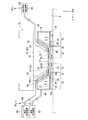
第1実施形態について説明する。図1は、第1実施形態に係る露光装置EXの一例を示す概略構成図である。本実施形態の露光装置EXは、露光液体LQを介して露光光ELで基板Pを露光する液浸露光装置である。本実施形態においては、露光装置EXは、露光液体LQを供給する第1供給口41を備えている。露光装置EXは、第1供給口41から供給された露光液体LQを介して露光光ELで基板Pを露光する。本実施形態においては、露光液体LQとして、水(純水)を用いる。なお、以下の説明において、露光液体LQを適宜、第1液体LQ、と称する。
<First Embodiment>
A first embodiment will be described. FIG. 1 is a schematic block diagram that shows an example of an exposure apparatus EX according to the first embodiment. The exposure apparatus EX of the present embodiment is an immersion exposure apparatus that exposes a substrate P with exposure light EL through an exposure liquid LQ. In the present embodiment, the exposure apparatus EX includes a first supply port 41 that supplies the exposure liquid LQ. The exposure apparatus EX exposes the substrate P with the exposure light EL through the exposure liquid LQ supplied from the first supply port 41. In the present embodiment, water (pure water) is used as the exposure liquid LQ. In the following description, the exposure liquid LQ is appropriately referred to as a first liquid LQ.

また、本実施形態においては、露光装置EX内の部材がクリーニング液体LC(図1には不図示)によってクリーニングされる。露光装置EXは、クリーニング液体LCを供給する第2供給口42を備えている。露光装置EXは、第2供給口42から供給されたクリーニング液体LCで露光装置EX内の部材をクリーニングする。なお、以下の説明において、クリーニング液体LCを適宜、第2液体LC、と称する。   In the present embodiment, the members in the exposure apparatus EX are cleaned by the cleaning liquid LC (not shown in FIG. 1). The exposure apparatus EX includes a second supply port 42 that supplies the cleaning liquid LC. The exposure apparatus EX cleans the members in the exposure apparatus EX with the cleaning liquid LC supplied from the second supply port 42. In the following description, the cleaning liquid LC is appropriately referred to as a second liquid LC.

第2液体LCは、露光装置EX内の部材をクリーニング可能な液体である。第2液体LCは、例えば露光装置EX内の部材に付着している異物(汚染物)を除去可能な液体である。本実施形態においては、第2液体LCとして、アルカリを含有するアルカリ洗浄液を用いる。アルカリ洗浄液は、例えばアンモニアを含む。第2液体LCとしてアルカリ洗浄液を用いることにより、露光装置EX内の部材に付着している、例えば有機物等の汚染物を良好に除去することができる。   The second liquid LC is a liquid that can clean the members in the exposure apparatus EX. The second liquid LC is a liquid that can remove foreign matters (contaminants) adhering to members in the exposure apparatus EX, for example. In the present embodiment, an alkali cleaning liquid containing alkali is used as the second liquid LC. The alkaline cleaning liquid contains, for example, ammonia. By using an alkaline cleaning liquid as the second liquid LC, it is possible to satisfactorily remove contaminants such as organic substances adhering to the members in the exposure apparatus EX.

本実施形態においては、露光装置EXが、例えば米国特許第6897963号明細書、欧州特許出願公開第1713113号明細書等に開示されているような、基板Pを保持して移動可能な基板ステージ1と、基板Pを保持せずに、露光に関する所定の計測を実行可能な計測器Cを搭載して移動可能な計測ステージ2とを備えた露光装置である場合を例にして説明する。   In the present embodiment, the exposure apparatus EX is capable of holding and moving the substrate stage 1 as disclosed in, for example, US Pat. No. 6,897,963 and European Patent Application No. 1713113. An example of an exposure apparatus that includes a movable measuring stage 2 mounted with a measuring instrument C that can perform predetermined measurement related to exposure without holding the substrate P will be described.

図1において、露光装置EXは、マスクMを保持して移動可能なマスクステージ3と、基板ステージ1と、計測ステージ2と、マスクMを露光光ELで照明する照明系ILと、露光光ELで照明されたマスクMのパターンの像を基板Pに投影する投影光学系PLと、露光光ELの光路の少なくとも一部が第1液体LQで満たされるように液浸空間LSを形成可能な液浸部材4と、露光装置EX全体の動作を制御する制御装置5とを備えている。   In FIG. 1, an exposure apparatus EX includes a mask stage 3 that can move while holding a mask M, a substrate stage 1, a measurement stage 2, an illumination system IL that illuminates the mask M with exposure light EL, and exposure light EL. A projection optical system PL that projects an image of the pattern of the mask M illuminated by the step P on the substrate P, and a liquid that can form the immersion space LS so that at least a part of the optical path of the exposure light EL is filled with the first liquid LQ. An immersion member 4 and a control device 5 for controlling the operation of the entire exposure apparatus EX are provided.

マスクMは、基板Pに投影されるデバイスパターンが形成されたレチクルを含む。マスクMは、例えばガラス板等の透明板上にクロム等の遮光膜を用いて所定のパターンが形成された透過型マスクを含む。なお、マスクMとして、反射型マスクを用いることもできる。基板Pは、デバイスを製造するための基板である。基板Pは、例えばシリコンウエハのような半導体ウエハ等の基材と、その基材上に形成された感光膜とを含む。感光膜は、感光材(フォトレジスト)の膜である。また、基板Pが、感光膜に加えて別の膜を含んでもよい。例えば、基板Pが、反射防止膜を含んでもよいし、感光膜を保護する保護膜(トップコート膜)を含んでもよい。   The mask M includes a reticle on which a device pattern projected onto the substrate P is formed. The mask M includes a transmission type mask in which a predetermined pattern is formed on a transparent plate such as a glass plate using a light shielding film such as chromium. A reflective mask can also be used as the mask M. The substrate P is a substrate for manufacturing a device. The substrate P includes a base material such as a semiconductor wafer such as a silicon wafer and a photosensitive film formed on the base material. The photosensitive film is a film of a photosensitive material (photoresist). Further, the substrate P may include another film in addition to the photosensitive film. For example, the substrate P may include an antireflection film or a protective film (topcoat film) that protects the photosensitive film.

照明系ILは、所定の照明領域IRを均一な照度分布の露光光ELで照明する。照明系ILは、照明領域IRに配置されたマスクMの少なくとも一部を均一な照度分布の露光光ELで照明する。照明系ILから射出される露光光ELとして、例えば水銀ランプから射出される輝線(g線、h線、i線)及びKrFエキシマレーザ光(波長248nm)等の遠紫外光(DUV光)、ArFエキシマレーザ光(波長193nm)、及びFレーザ光(波長157nm)等の真空紫外光(VUV光)等が用いられる。本実施形態においては、露光光ELとして、紫外光(真空紫外光)であるArFエキシマレーザ光を用いる。 The illumination system IL illuminates a predetermined illumination region IR with exposure light EL having a uniform illuminance distribution. The illumination system IL illuminates at least a part of the mask M arranged in the illumination region IR with the exposure light EL having a uniform illuminance distribution. As the exposure light EL emitted from the illumination system IL, for example, far ultraviolet light (DUV light) such as bright lines (g-line, h-line, i-line) and KrF excimer laser light (wavelength 248 nm) emitted from a mercury lamp, ArF Excimer laser light (wavelength 193 nm), vacuum ultraviolet light (VUV light) such as F 2 laser light (wavelength 157 nm), or the like is used. In the present embodiment, ArF excimer laser light, which is ultraviolet light (vacuum ultraviolet light), is used as the exposure light EL.

マスクステージ3は、マスクMをリリース可能に保持するマスク保持部6を有する。本実施形態において、マスク保持部6は、マスクMのパターン形成面(下面)とXY平面とがほぼ平行となるように、マスクMを保持する。マスクステージ3は、マスクMを保持した状態で、照明領域IRを含むXY平面内を移動可能である。本実施形態においては、マスクステージ3は、例えばリニアモータ等のアクチュエータを含む第1駆動システム7の作動により、X軸、Y軸、及びθZ方向の3つの方向に移動可能である。   The mask stage 3 has a mask holding unit 6 that holds the mask M in a releasable manner. In the present embodiment, the mask holding unit 6 holds the mask M so that the pattern formation surface (lower surface) of the mask M and the XY plane are substantially parallel. The mask stage 3 is movable in the XY plane including the illumination area IR while holding the mask M. In the present embodiment, the mask stage 3 is movable in three directions of the X axis, the Y axis, and the θZ direction by the operation of the first drive system 7 including an actuator such as a linear motor.

マスクステージ3(マスクM)の位置情報は、干渉計システム8のレーザ干渉計8Aによって計測される。レーザ干渉計8Aは、マスクステージ3に設けられた反射ミラー3Rを用いて位置情報を計測する。制御装置5は、レーザ干渉計8Aの計測結果に基づいて第1駆動システム7を作動し、マスクステージ3に保持されているマスクMの位置制御を行う。   The position information of the mask stage 3 (mask M) is measured by the laser interferometer 8A of the interferometer system 8. The laser interferometer 8 </ b> A measures position information using a reflection mirror 3 </ b> R provided on the mask stage 3. The control device 5 operates the first drive system 7 based on the measurement result of the laser interferometer 8A, and controls the position of the mask M held on the mask stage 3.

投影光学系PLは、所定の投影領域PRに露光光ELを照射する。投影光学系PLは、投影領域PRに配置された基板Pの少なくとも一部に、マスクMのパターンの像を所定の投影倍率で投影する。投影光学系PLの複数の光学素子は、鏡筒9に保持されている。本実施形態の投影光学系PLは、その投影倍率が例えば1/4、1/5、又は1/8等の縮小系である。なお、投影光学系PLは等倍系及び拡大系のいずれでもよい。本実施形態においては、投影光学系PLの光軸AXはZ軸と平行である。また、投影光学系PLは、反射光学素子を含まない屈折系、屈折光学素子を含まない反射系、反射光学素子と屈折光学素子とを含む反射屈折系のいずれであってもよい。また、投影光学系PLは、倒立像と正立像とのいずれを形成してもよい。   The projection optical system PL irradiates the predetermined projection region PR with the exposure light EL. The projection optical system PL projects an image of the pattern of the mask M at a predetermined projection magnification onto at least a part of the substrate P arranged in the projection region PR. A plurality of optical elements of the projection optical system PL are held by the lens barrel 9. The projection optical system PL of the present embodiment is a reduction system whose projection magnification is, for example, 1/4, 1/5, or 1/8. Note that the projection optical system PL may be either an equal magnification system or an enlargement system. In the present embodiment, the optical axis AX of the projection optical system PL is parallel to the Z axis. The projection optical system PL may be any of a refractive system that does not include a reflective optical element, a reflective system that does not include a refractive optical element, and a catadioptric system that includes a reflective optical element and a refractive optical element. Further, the projection optical system PL may form either an inverted image or an erect image.

基板ステージ1及び計測ステージ2のそれぞれは、ベース部材10のガイド面11上を移動可能である。本実施形態においては、ガイド面11は、XY平面とほぼ平行である。   Each of the substrate stage 1 and the measurement stage 2 is movable on the guide surface 11 of the base member 10. In the present embodiment, the guide surface 11 is substantially parallel to the XY plane.

基板ステージ1は、基板Pを保持した状態で、投影領域PRを含むXY平面内をガイド面11に沿って移動可能である。計測ステージ2は、少なくとも1つの計測器Cを搭載した状態で、投影領域PRを含むXY平面内をガイド面11に沿って移動可能である。本実施形態において、基板ステージ1及び計測ステージ2のそれぞれは、例えばリニアモータ等のアクチュエータを含む第2駆動システム12の作動により、X軸、Y軸、Z軸、θX、θY、及びθZ方向の6つの方向に移動可能である。   The substrate stage 1 is movable along the guide surface 11 in the XY plane including the projection region PR while holding the substrate P. The measurement stage 2 is movable along the guide surface 11 in the XY plane including the projection region PR in a state where at least one measuring instrument C is mounted. In the present embodiment, each of the substrate stage 1 and the measurement stage 2 is moved in the X axis, Y axis, Z axis, θX, θY, and θZ directions by the operation of the second drive system 12 including an actuator such as a linear motor. It can move in six directions.

本実施形態において、投影光学系PL及び液浸部材4の位置はほぼ固定されている。基板ステージ1及び計測ステージ2のそれぞれは、投影光学系PL及び液浸部材4に対して可動である。   In the present embodiment, the positions of the projection optical system PL and the liquid immersion member 4 are substantially fixed. Each of the substrate stage 1 and the measurement stage 2 is movable with respect to the projection optical system PL and the liquid immersion member 4.

基板ステージ1(基板P)及び計測ステージ2(計測器C)の位置情報は、干渉計システム8のレーザ干渉計8Bによって計測される。レーザ干渉計8Bは、基板ステージ1に設けられた反射ミラー1R、及び計測ステージ2に設けられた反射ミラー2Rを用いて位置情報を計測する。また、基板ステージ1に保持されている基板Pの表面の位置情報(Z軸、θX、及びθY方向に関する位置情報)が、フォーカス・レベリング検出システム(不図示)によって検出される。フォーカス・レベリング検出システムは、基板Pの表面の位置情報のみならず、基板ステージ1の上面13、及び計測ステージ2の上面14の位置情報を検出可能である。制御装置5は、レーザ干渉計8Bの計測結果及びフォーカス・レベリング検出システムの検出結果に基づいて第2駆動システム12を作動し、基板ステージ1に保持されている基板Pの位置制御、及び計測ステージ2に搭載されている計測器Cの位置制御を行う。   Position information of the substrate stage 1 (substrate P) and the measurement stage 2 (measurement device C) is measured by the laser interferometer 8B of the interferometer system 8. The laser interferometer 8B measures position information using a reflection mirror 1R provided on the substrate stage 1 and a reflection mirror 2R provided on the measurement stage 2. Further, position information (position information regarding the Z axis, θX, and θY directions) of the surface of the substrate P held on the substrate stage 1 is detected by a focus / leveling detection system (not shown). The focus / leveling detection system can detect not only the position information of the surface of the substrate P but also the position information of the upper surface 13 of the substrate stage 1 and the upper surface 14 of the measurement stage 2. The control device 5 operates the second drive system 12 based on the measurement result of the laser interferometer 8B and the detection result of the focus / leveling detection system, and controls the position of the substrate P held on the substrate stage 1 and the measurement stage. 2 controls the position of the measuring instrument C mounted on the unit 2.

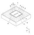
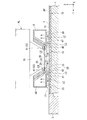
図2は、基板ステージ1及び計測ステージ2を上方から見た平面図、図3は、側断面図である。図2及び図3において、基板ステージ1は、基板Pをリリース可能に保持する基板保持部15を備えている。基板保持部15は、基板Pの裏面と対向し、基板Pの裏面を保持する。基板ステージ1の上面13は、基板保持部15の周囲に配置されている。基板保持部15は、基板Pの表面とXY平面とがほぼ平行となるように、基板Pを保持する。本実施形態においては、基板保持部15に保持された基板Pの表面と基板ステージ1の上面13とは、ほぼ平行である。また、本実施形態においては、基板保持部15に保持された基板Pの表面と基板ステージ1の上面13とは、ほぼ同一平面内に配置される(ほぼ面一である)。   FIG. 2 is a plan view of the substrate stage 1 and the measurement stage 2 as viewed from above, and FIG. 3 is a side sectional view. 2 and 3, the substrate stage 1 includes a substrate holding part 15 that holds the substrate P so as to be releasable. The substrate holding unit 15 faces the back surface of the substrate P and holds the back surface of the substrate P. The upper surface 13 of the substrate stage 1 is disposed around the substrate holding unit 15. The substrate holding unit 15 holds the substrate P so that the surface of the substrate P and the XY plane are substantially parallel. In the present embodiment, the surface of the substrate P held by the substrate holding unit 15 and the upper surface 13 of the substrate stage 1 are substantially parallel. In the present embodiment, the surface of the substrate P held by the substrate holding unit 15 and the upper surface 13 of the substrate stage 1 are arranged in substantially the same plane (substantially flush).

本実施形態においては、基板ステージ1は、基板Pの周囲に配置されるプレート部材Tと、基板保持部15の周囲に配置され、プレート部材Tをリリース可能に保持するプレート部材保持部16とを有する。プレート部材保持部16は、プレート部材Tの下面と対向し、プレート部材Tの下面を保持する。以下の説明において、基板保持部15を適宜、第1保持部15、と称し、プレート部材保持部16を適宜、第2保持部16、と称する。   In the present embodiment, the substrate stage 1 includes a plate member T disposed around the substrate P, and a plate member holding unit 16 disposed around the substrate holding unit 15 and configured to releasably hold the plate member T. Have. The plate member holding portion 16 faces the lower surface of the plate member T and holds the lower surface of the plate member T. In the following description, the substrate holding part 15 is appropriately referred to as a first holding part 15, and the plate member holding part 16 is appropriately referred to as a second holding part 16.

プレート部材Tは、基板Pを配置可能な開口THを有する。第2保持部16に保持されたプレート部材Tは、第1保持部15に保持された基板Pの周囲に配置される。本実施形態においては、基板ステージ1の上面13は、第2保持部16に保持されたプレート部材Tの上面を含む。   The plate member T has an opening TH in which the substrate P can be disposed. The plate member T held by the second holding unit 16 is disposed around the substrate P held by the first holding unit 15. In the present embodiment, the upper surface 13 of the substrate stage 1 includes the upper surface of the plate member T held by the second holding unit 16.

本実施形態において、第2保持部16に保持されたプレート部材Tの開口THの内面(内側エッジ)と、第1保持部15に保持された基板Pの外面(外側エッジ)とは、所定のギャップを介して対向するように配置される。第2保持部16は、プレート部材Tの上面13とXY平面とがほぼ平行となるように、プレート部材Tを保持する。また、第2保持部16は、プレート部材Tの上面13と第1保持部15に保持された基板Pの表面とがほぼ面一となるように、プレート部材Tを保持する。   In the present embodiment, the inner surface (inner edge) of the opening TH of the plate member T held by the second holding unit 16 and the outer surface (outer edge) of the substrate P held by the first holding unit 15 are predetermined. It arrange | positions so that it may oppose through a gap. The second holding unit 16 holds the plate member T so that the upper surface 13 of the plate member T and the XY plane are substantially parallel. The second holding unit 16 holds the plate member T so that the upper surface 13 of the plate member T and the surface of the substrate P held by the first holding unit 15 are substantially flush with each other.

第1保持部15及び第2保持部16のそれぞれは、所謂、ピンチャック機構の少なくとも一部を構成する。図3に示すように、第1保持部15は、基板ステージ1の第1チャック面17に配置され、基板Pの裏面を支持する複数の凸部15Pと、第1チャック面17において複数の凸部15Pの周囲に配置された第1周壁15Aと、第1周壁15Aの内側の第1チャック面17に複数設けられ、気体を吸引可能な第1吸引口15Bとを備えている。第2保持部16は、基板ステージ1の第2チャック面18において第1周壁15Aの周囲に形成された第2周壁16Aと、第2チャック面18において第2周壁16Aの周囲に形成された第3周壁16Cと、第2周壁16Aと第3周壁16Cとの間の第2チャック面18に形成され、プレート部材Tの下面を支持する複数の凸部16Pと、第2周壁16Aと第3周壁16Cとの間の第2チャック面18に複数設けられ、気体を吸引可能な第2吸引口16Bとを備えている。   Each of the first holding part 15 and the second holding part 16 constitutes at least a part of a so-called pin chuck mechanism. As shown in FIG. 3, the first holding unit 15 is disposed on the first chuck surface 17 of the substrate stage 1, and includes a plurality of convex portions 15 </ b> P that support the back surface of the substrate P, and a plurality of convex portions on the first chuck surface 17. A plurality of first peripheral walls 15A arranged around the portion 15P and a first suction port 15B provided on the first chuck surface 17 inside the first peripheral wall 15A and capable of sucking gas. The second holding unit 16 includes a second peripheral wall 16A formed around the first peripheral wall 15A on the second chuck surface 18 of the substrate stage 1 and a second peripheral wall 16A formed around the second peripheral wall 16A on the second chuck surface 18. A plurality of convex portions 16P formed on the third peripheral wall 16C, the second chuck surface 18 between the second peripheral wall 16A and the third peripheral wall 16C and supporting the lower surface of the plate member T, and the second peripheral wall 16A and the third peripheral wall A plurality of second suction ports 16 </ b> B are provided on the second chuck surface 18 between 16 </ b> C and capable of sucking gas.

基板Pの裏面と第1周壁15Aと第1チャック面17とで囲まれた空間の気体が第1吸引口15Bにより吸引され、その空間が負圧になることによって、基板Pの裏面が凸部15Pに吸着保持される。また、第1吸引口15Bを用いる吸引動作が停止されることによって、第1保持部15より基板Pを外すことができる。また、プレート部材Tの下面と第2周壁16Aと第3周壁16Cと第2チャック面18とで囲まれた空間の気体が第2吸引口16Bにより吸引され、その空間が負圧になることによって、プレート部材Tの下面が凸部16Pに吸着保持される。また、第2吸引口16Bを用いる吸引動作が停止されることによって、第2保持部16よりプレート部材Tを外すことができる。   The gas in the space surrounded by the back surface of the substrate P, the first peripheral wall 15A, and the first chuck surface 17 is sucked by the first suction port 15B, and the space becomes negative pressure. Adsorbed and held at 15P. Further, the substrate P can be removed from the first holding unit 15 by stopping the suction operation using the first suction port 15B. Further, the gas in the space surrounded by the lower surface of the plate member T, the second peripheral wall 16A, the third peripheral wall 16C, and the second chuck surface 18 is sucked by the second suction port 16B, and the space becomes negative pressure. The lower surface of the plate member T is attracted and held by the convex portion 16P. Further, the plate member T can be removed from the second holding portion 16 by stopping the suction operation using the second suction port 16B.

計測ステージ2は、露光に関する計測を実行可能な計測器Cを備えている。計測器Cは、計測部材(光学部品)を含む。本実施形態において、計測ステージ2の上面14の所定位置には、計測器(計測部材)Cとして、露光光ELを透過可能な開口パターンが形成されたスリット板C1が配置されている。スリット板C1は、例えば米国特許出願公開第2002/0041377号明細書に開示されているような、投影光学系PLによる空間像を計測可能な空間像計測システムの一部を構成する。空間像計測システムは、スリット板C1と、スリット板C1の開口パターンを介した露光光ELを受光する受光素子とを備えている。制御装置5は、スリット板C1に露光光ELを照射し、そのスリット板C1の開口パターンを介した露光光ELを受光素子で受光して、投影光学系PLの結像特性の計測を実行する。   The measurement stage 2 includes a measuring device C that can perform measurement related to exposure. The measuring instrument C includes a measuring member (optical component). In the present embodiment, a slit plate C1 having an opening pattern capable of transmitting the exposure light EL is disposed as a measuring instrument (measuring member) C at a predetermined position on the upper surface 14 of the measuring stage 2. The slit plate C1 constitutes a part of an aerial image measurement system capable of measuring an aerial image by the projection optical system PL as disclosed in, for example, US Patent Application Publication No. 2002/0041377. The aerial image measurement system includes a slit plate C1 and a light receiving element that receives the exposure light EL through the opening pattern of the slit plate C1. The control device 5 irradiates the slit plate C1 with the exposure light EL, receives the exposure light EL through the opening pattern of the slit plate C1 by the light receiving element, and executes the measurement of the imaging characteristics of the projection optical system PL. .

また、計測ステージ2の上面14の所定位置には、計測器(計測部材)Cとして、露光光ELを透過可能な透過パターンが形成された上板C2が配置されている。上板C2は、例えば米国特許第4465368号明細書に開示されているような、露光光ELの照度むらを計測可能な照度むら計測システムの一部を構成する。照度むら計測システムは、上板C2と、上板C2の開口パターンを介した露光光ELを受光する受光素子とを備えている。制御装置5は、上板C2に露光光ELを照射し、その上板C2の開口パターンを介した露光光ELを受光素子で受光して、露光光ELの照度むらの計測を実行する。   Further, an upper plate C2 on which a transmission pattern capable of transmitting the exposure light EL is formed as a measuring instrument (measuring member) C is disposed at a predetermined position on the upper surface 14 of the measuring stage 2. The upper plate C2 constitutes a part of an illuminance unevenness measurement system capable of measuring the illuminance unevenness of the exposure light EL as disclosed in, for example, US Pat. No. 4,465,368. The illuminance unevenness measurement system includes an upper plate C2 and a light receiving element that receives exposure light EL through an opening pattern of the upper plate C2. The control device 5 irradiates the upper plate C2 with the exposure light EL, receives the exposure light EL through the opening pattern of the upper plate C2 by the light receiving element, and executes the measurement of the illuminance unevenness of the exposure light EL.

なお、上板C2が、例えば米国特許第6721039号明細書に開示されているような、投影光学系PLの露光光ELの透過率の変動量を計測可能な計測システム、例えば米国特許出願公開第2002/0061469号明細書等に開示されているような、照射量計測システム(照度計測システム)、例えば欧州特許第1079223号明細書に開示されているような、波面収差計測システム等、露光光ELの露光エネルギーに関する情報を計測可能な計測システムの一部を構成するものであってもよい。その場合、露光装置EXは、それら計測システムの一部を構成する受光素子を備えている。   Note that the upper plate C2 is a measurement system capable of measuring the variation in the transmittance of the exposure light EL of the projection optical system PL, as disclosed in, for example, US Pat. No. 6,721,039, for example, US Pat. Exposure light EL such as a dose measurement system (illuminance measurement system) as disclosed in the specification of 2002/0061469, for example, a wavefront aberration measurement system as disclosed in the specification of European Patent No. 1079223 It may constitute a part of a measurement system capable of measuring information on the exposure energy. In that case, the exposure apparatus EX includes a light receiving element that constitutes a part of the measurement system.

また、計測ステージ2の上面14の所定位置には、計測器(計測部材)Cとして、基準板C3が配置されている。基準板C3は、例えば米国特許第5493403号明細書に開示されているようなFIA(Field Image Alignment)方式のアライメントシステムで計測される基準マークを有する。   A reference plate C3 is disposed as a measuring instrument (measuring member) C at a predetermined position on the upper surface 14 of the measuring stage 2. The reference plate C3 has a reference mark measured by an FIA (Field Image Alignment) type alignment system as disclosed in, for example, US Pat. No. 5,493,403.

また、計測ステージ2の上面14の所定位置には、計測器(計測部材)Cとして、光を透過可能な上板C4が配置されている。上板C4は、例えば欧州特許出願公開第1791164号明細書に開示されているような、投影光学系PL及び液浸部材4等の光学像(画像)を取得可能な観察システムの一部を構成する。観察システムは、上板C4と、上板C4を介して画像を取得する撮像装置(観察カメラ)とを備えている。制御装置5は、投影光学系PL及び液浸部材4の少なくとも一方と上板C4とを対向させて、画像を取得する。   Further, an upper plate C4 capable of transmitting light is disposed as a measuring instrument (measuring member) C at a predetermined position on the upper surface 14 of the measuring stage 2. The upper plate C4 constitutes a part of an observation system capable of acquiring optical images (images) such as the projection optical system PL and the liquid immersion member 4 as disclosed in, for example, European Patent Application Publication No. 1791164. To do. The observation system includes an upper plate C4 and an imaging device (observation camera) that acquires an image via the upper plate C4. The control device 5 acquires an image by causing at least one of the projection optical system PL and the liquid immersion member 4 and the upper plate C4 to face each other.

本実施形態においては、スリット板C1の上面と、上板C2の上面と、基準板C3の上面と、上板C4の上面と、計測ステージ2の上面14とは、ほぼ同一平面内(XY平面内)に配置される(ほぼ面一である)。   In the present embodiment, the upper surface of the slit plate C1, the upper surface of the upper plate C2, the upper surface of the reference plate C3, the upper surface of the upper plate C4, and the upper surface 14 of the measurement stage 2 are substantially in the same plane (XY plane). Inside) (almost flush).

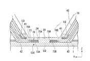
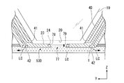
次に、液浸部材4について、図4〜図7を参照して説明する。図4は、液浸部材4の近傍を示すYZ平面と平行な側断面図、図5は、XZ平面と平行な側断面図、図6は、液浸部材4を示す概略斜視図の一部破断図、図7は、液浸部材4を下側(−Z側)から見た斜視図である。図4及び図5は、第1液体LQを介して基板Pが露光されているときの状態を示す。   Next, the liquid immersion member 4 will be described with reference to FIGS. 4 is a side sectional view parallel to the YZ plane showing the vicinity of the liquid immersion member 4, FIG. 5 is a side sectional view parallel to the XZ plane, and FIG. 6 is a part of a schematic perspective view showing the liquid immersion member 4. FIG. 7 is a perspective view of the liquid immersion member 4 as viewed from below (−Z side). 4 and 5 show a state in which the substrate P is exposed through the first liquid LQ.

液浸部材4は、露光光ELの光路の少なくとも一部が第1液体LQで満たされるように液浸空間LSを形成する。液浸空間LSは、液体で満たされた部分(空間、領域)である。   The liquid immersion member 4 forms the liquid immersion space LS so that at least a part of the optical path of the exposure light EL is filled with the first liquid LQ. The immersion space LS is a portion (space, region) filled with liquid.

液浸部材4は、投影光学系PLの複数の光学素子のうち、投影光学系PLの像面に最も近い終端光学素子19の近傍に配置される。終端光学素子19は、投影光学系PLの像面に向けて露光光ELを射出する射出面(下面)20を有する。本実施形態において、液浸部材4は、終端光学素子19から射出される露光光ELの光路が第1液体LQで満たされるように液浸空間LSを形成可能である。   The liquid immersion member 4 is disposed in the vicinity of the terminal optical element 19 closest to the image plane of the projection optical system PL among the plurality of optical elements of the projection optical system PL. The last optical element 19 has an emission surface (lower surface) 20 that emits the exposure light EL toward the image plane of the projection optical system PL. In the present embodiment, the liquid immersion member 4 can form the liquid immersion space LS so that the optical path of the exposure light EL emitted from the last optical element 19 is filled with the first liquid LQ.

終端光学素子19は、例えば合成石英で形成される。なお、終端光学素子19が、蛍石で形成されてもよい。液浸部材4は、例えばチタンで形成される。なお、液浸部材4が、ステンレスで形成されてもよい。   The terminal optical element 19 is made of, for example, synthetic quartz. The terminal optical element 19 may be made of fluorite. The liquid immersion member 4 is made of, for example, titanium. The liquid immersion member 4 may be formed of stainless steel.

液浸部材4は、終端光学素子19と、射出面20から射出される露光光ELの照射位置に配置された所定部材との間の露光光ELの光路が第1液体LQで満たされるように液浸空間LSを形成する。本実施形態において、射出面20から射出される露光光ELの照射位置(照射領域)は、射出面20と対向する位置を含み、投影光学系PLの投影領域PRを含む。以下の説明において、射出面20から射出される露光光ELの照射位置を適宜、露光位置、と称する。   The liquid immersion member 4 is configured so that the optical path of the exposure light EL between the terminal optical element 19 and the predetermined member disposed at the irradiation position of the exposure light EL emitted from the emission surface 20 is filled with the first liquid LQ. The immersion space LS is formed. In the present embodiment, the irradiation position (irradiation region) of the exposure light EL emitted from the emission surface 20 includes a position facing the emission surface 20 and includes the projection region PR of the projection optical system PL. In the following description, the irradiation position of the exposure light EL emitted from the emission surface 20 is appropriately referred to as an exposure position.

液浸部材4は、射出面20から射出される露光光ELの光路の周囲に配置され、露光位置に配置された所定部材の表面との間で第1液体LQを保持可能な下面21を有する。本実施形態において、射出面20と対向可能な所定部材は、下面21と対向可能である。所定部材の表面が射出面20と対向する位置に配置されたとき、下面21の少なくとも一部と所定部材の表面とが対向する。射出面20と所定部材の表面とが対向しているとき、終端光学素子19の射出面20と所定部材の表面との間の空間は第1液体LQを保持可能である。また、下面21と所定部材の表面とが対向しているとき、液浸部材4の下面21と所定部材の表面との間の空間は第1液体LQを保持可能である。一方側の射出面20及び下面21と他方側の所定部材の表面との間に第1液体LQが保持されることによって、終端光学素子19の射出面20と所定部材の表面との間の露光光ELの光路が第1液体LQで満たされるように液浸空間LSが形成される。   The liquid immersion member 4 is disposed around the optical path of the exposure light EL emitted from the emission surface 20, and has a lower surface 21 that can hold the first liquid LQ with the surface of a predetermined member disposed at the exposure position. . In the present embodiment, the predetermined member that can face the emission surface 20 can face the lower surface 21. When the surface of the predetermined member is disposed at a position facing the emission surface 20, at least a part of the lower surface 21 and the surface of the predetermined member are opposed. When the emission surface 20 faces the surface of the predetermined member, the space between the emission surface 20 of the last optical element 19 and the surface of the predetermined member can hold the first liquid LQ. Further, when the lower surface 21 and the surface of the predetermined member are opposed to each other, the space between the lower surface 21 of the liquid immersion member 4 and the surface of the predetermined member can hold the first liquid LQ. Exposure between the exit surface 20 of the last optical element 19 and the surface of the predetermined member is performed by holding the first liquid LQ between the exit surface 20 and the lower surface 21 on the one side and the surface of the predetermined member on the other side. The immersion space LS is formed so that the optical path of the light EL is filled with the first liquid LQ.

本実施形態において、射出面20及び下面21と対向可能な所定部材は、終端光学素子19の射出側(像面側)で、終端光学素子19及び液浸部材4に対して可動な部材を含み、露光位置を含む所定面内を、露光光ELの光路に対して移動可能な部材を含む。本実施形態において、その所定部材は、基板ステージ1、及び計測ステージ2の少なくとも一方を含む。また、その所定部材は、基板ステージ1に保持された基板P、及び計測ステージ2に搭載された計測器Cの少なくとも一方を含む。   In the present embodiment, the predetermined member that can face the exit surface 20 and the lower surface 21 includes a member that is movable relative to the end optical element 19 and the liquid immersion member 4 on the exit side (image surface side) of the end optical element 19. And a member that can move in a predetermined plane including the exposure position with respect to the optical path of the exposure light EL. In the present embodiment, the predetermined member includes at least one of the substrate stage 1 and the measurement stage 2. The predetermined member includes at least one of the substrate P held on the substrate stage 1 and the measuring instrument C mounted on the measurement stage 2.

基板Pの露光時、基板ステージ1に保持された基板Pが、終端光学素子19及び液浸部材4と対向するように、露光位置に配置される。少なくとも基板Pの露光時、終端光学素子19の射出面20から射出される露光光ELの光路が第1液体LQで満たされるように、一方側の終端光学素子19及び液浸部材4と他方側の基板Pとの間に第1液体LQが保持され、液浸空間LSが形成される。   When the substrate P is exposed, the substrate P held on the substrate stage 1 is disposed at the exposure position so as to face the terminal optical element 19 and the liquid immersion member 4. At least during exposure of the substrate P, the one end optical element 19 and the liquid immersion member 4 and the other side are arranged so that the optical path of the exposure light EL emitted from the exit surface 20 of the end optical element 19 is filled with the first liquid LQ. The first liquid LQ is held between the substrate P and the immersion space LS.

本実施形態においては、基板Pに露光光ELが照射されているとき、投影光学系PLの投影領域PRを含む基板Pの表面の一部の領域が第1液体LQで覆われるように液浸空間LSが形成される。すなわち、第1液体LQの界面(メニスカス、エッジ)LGの少なくとも一部は、液浸部材4の下面21と基板Pの表面との間に形成される。すなわち、本実施形態の露光装置EXは、局所液浸方式を採用する。   In the present embodiment, when the exposure light EL is irradiated onto the substrate P, the liquid immersion is performed so that a partial region of the surface of the substrate P including the projection region PR of the projection optical system PL is covered with the first liquid LQ. A space LS is formed. That is, at least a part of the interface (meniscus, edge) LG of the first liquid LQ is formed between the lower surface 21 of the liquid immersion member 4 and the surface of the substrate P. That is, the exposure apparatus EX of the present embodiment employs a local liquid immersion method.

なお、以下の説明においては、説明を簡単にするため、主に、終端光学素子19の射出面20及び液浸部材4の下面21と対向する位置に基板Pが配置されている状態を例にして説明する。   In the following description, in order to simplify the description, the state in which the substrate P is disposed mainly at a position facing the exit surface 20 of the last optical element 19 and the lower surface 21 of the liquid immersion member 4 is taken as an example. I will explain.

図4〜図7に示すように、液浸部材4は、環状の部材である。液浸部材4は、露光光ELの光路の周囲に配置されている。本実施形態においては、液浸部材4は、終端光学素子19の周囲に配置される第1プレート部22と、Z軸方向に関して少なくとも一部が終端光学素子19の射出面20と基板Pの表面との間に配置される第2プレート部23とを有する。   As shown in FIGS. 4 to 7, the liquid immersion member 4 is an annular member. The liquid immersion member 4 is disposed around the optical path of the exposure light EL. In the present embodiment, the liquid immersion member 4 includes a first plate portion 22 disposed around the terminal optical element 19, and at least a part of the exit surface 20 of the terminal optical element 19 and the surface of the substrate P in the Z-axis direction. 2nd plate part 23 arrange | positioned between.

第1プレート部22は、終端光学素子19の外周面と対向し、その外周面に沿って形成された内周面を有する。液浸部材4の内周面と、終端光学素子19の外周面とは、所定の間隙を介して対向する。   The first plate portion 22 is opposed to the outer peripheral surface of the last optical element 19 and has an inner peripheral surface formed along the outer peripheral surface. The inner peripheral surface of the liquid immersion member 4 and the outer peripheral surface of the last optical element 19 are opposed to each other with a predetermined gap.

第2プレート部23は、中央に開口24を有する。終端光学素子19の射出面20から射出された露光光ELは、開口24を通過可能である。例えば、基板Pの露光中、射出面20から射出された露光光ELは、開口24を通過し、第1液体LQを介して基板Pの表面に照射される。本実施形態においては、開口24における露光光ELの断面形状はX軸方向を長手方向とする略矩形状(スリット状)である。開口24は、露光光ELの断面形状に応じて、XY方向において略矩形状(スリット状)に形成されている。また、開口24における露光光ELの断面形状と、基板Pにおける投影光学系PLの投影領域PRの形状とはほぼ同じである。   The second plate portion 23 has an opening 24 at the center. The exposure light EL emitted from the exit surface 20 of the last optical element 19 can pass through the opening 24. For example, during the exposure of the substrate P, the exposure light EL emitted from the emission surface 20 passes through the opening 24 and is irradiated onto the surface of the substrate P through the first liquid LQ. In the present embodiment, the cross-sectional shape of the exposure light EL in the opening 24 is a substantially rectangular shape (slit shape) whose longitudinal direction is the X-axis direction. The opening 24 is formed in a substantially rectangular shape (slit shape) in the XY direction according to the cross-sectional shape of the exposure light EL. The cross-sectional shape of the exposure light EL in the opening 24 and the shape of the projection region PR of the projection optical system PL on the substrate P are substantially the same.

本実施形態において、液浸部材4は、開口24の周囲に配置され、終端光学素子19の射出面20と所定の間隙を介して対向する上面25を有する。本実施形態においては、上面25は、第2プレート部23の上面を含む。本実施形態において、上面25は、開口24の周囲に配置された平坦面である。上面25は、XY平面とほぼ平行である。上面25は、開口24の上側(+Z側)の空間26と面する。空間26は、上面25と射出面20との間の空間を含む。以下の説明において、空間26を適宜、上側空間26、と称する。なお、上面25は、曲面であってもよいし、凹凸を有していてもよい。   In the present embodiment, the liquid immersion member 4 has an upper surface 25 that is disposed around the opening 24 and faces the exit surface 20 of the last optical element 19 with a predetermined gap therebetween. In the present embodiment, the upper surface 25 includes the upper surface of the second plate portion 23. In the present embodiment, the upper surface 25 is a flat surface disposed around the opening 24. The upper surface 25 is substantially parallel to the XY plane. The upper surface 25 faces the space 26 above the opening 24 (+ Z side). The space 26 includes a space between the upper surface 25 and the emission surface 20. In the following description, the space 26 is appropriately referred to as the upper space 26. The upper surface 25 may be a curved surface or may have irregularities.

液浸部材4の下面21は、第2プレート部23の下面と、第2プレート部23の周囲に配置された多孔部材27の下面とを含む。本実施形態において、XY平面における第2プレート部23の下面の外形は、ほぼ正方形である。多孔部材27は、複数の孔(openingsあるいはpores)を含むプレート状の部材である。なお、多孔部材27が、網目状に多数の小さい孔が形成された多孔部材であるメッシュフィルタでもよい。本実施形態においては、XY平面内における多孔部材27の形状は、矩形の環状である。多孔部材27は、チタン製である。なお、多孔部材27が、ステンレス製でもよい。   The lower surface 21 of the liquid immersion member 4 includes a lower surface of the second plate portion 23 and a lower surface of the porous member 27 disposed around the second plate portion 23. In the present embodiment, the outer shape of the lower surface of the second plate portion 23 in the XY plane is substantially square. The porous member 27 is a plate-like member including a plurality of holes (openings or pores). The porous member 27 may be a mesh filter that is a porous member in which a large number of small holes are formed in a mesh shape. In the present embodiment, the shape of the porous member 27 in the XY plane is a rectangular ring shape. The porous member 27 is made of titanium. The porous member 27 may be made of stainless steel.

液浸部材4の下面21は、開口24の周囲に配置された第1領域31と、第1領域31の周囲に配置された第2領域32と、第2領域32の周囲に配置された第3領域33とを含む。本実施形態において、第2プレート部23の下面は、第1領域31及び第2領域32を含み、多孔部材27の下面は、第3領域33を含む。   The lower surface 21 of the liquid immersion member 4 includes a first region 31 disposed around the opening 24, a second region 32 disposed around the first region 31, and a second region disposed around the second region 32. 3 regions 33. In the present embodiment, the lower surface of the second plate portion 23 includes a first region 31 and a second region 32, and the lower surface of the porous member 27 includes a third region 33.

第1領域31は、開口24の周囲に配置された平坦面である。平坦面(第1領域)31は、基板Pの表面(XY平面)とほぼ平行である。平坦面31は、開口24の下側(+Z側)の空間28と面する。空間28は、平坦面31と基板Pの表面との間の空間を含む。平坦面31と基板Pの表面との間の空間は、第1液体LQを保持可能である。以下の説明において、空間28を適宜、下側空間28、と称する。   The first region 31 is a flat surface disposed around the opening 24. The flat surface (first region) 31 is substantially parallel to the surface (XY plane) of the substrate P. The flat surface 31 faces the space 28 on the lower side (+ Z side) of the opening 24. The space 28 includes a space between the flat surface 31 and the surface of the substrate P. A space between the flat surface 31 and the surface of the substrate P can hold the first liquid LQ. In the following description, the space 28 is appropriately referred to as a lower space 28.

第2領域32は、平坦面31の周囲に配置された溝29を有する。本実施形態において、XY平面内における溝29の形状は、矩形の環状である。   The second region 32 has a groove 29 disposed around the flat surface 31. In the present embodiment, the shape of the groove 29 in the XY plane is a rectangular ring.

第3領域33は、液体を回収可能な液体回収面を含む。本実施形態において、液体回収面(第3領域)33は、基板Pの表面(XY平面)とほぼ平行である。液体回収面33は、基板Pの露光中、その液体回収面33と対向する基板P上の第1液体LQを回収可能である。液体回収面33は、多孔部材27の下面を含む。液体回収面33と対向する位置に配置された基板P上の第1液体LQの少なくとも一部は、多孔部材27の孔を介して回収される。液体回収面33は、その液体回収面33(多孔部材27の下面)に接触した液体を回収可能である。   The third region 33 includes a liquid recovery surface that can recover the liquid. In the present embodiment, the liquid recovery surface (third region) 33 is substantially parallel to the surface (XY plane) of the substrate P. The liquid recovery surface 33 can recover the first liquid LQ on the substrate P facing the liquid recovery surface 33 during the exposure of the substrate P. The liquid recovery surface 33 includes the lower surface of the porous member 27. At least a part of the first liquid LQ on the substrate P arranged at a position facing the liquid recovery surface 33 is recovered through the hole of the porous member 27. The liquid recovery surface 33 can recover the liquid in contact with the liquid recovery surface 33 (the lower surface of the porous member 27).

本実施形態においては、Z軸方向に関して、平坦面31の位置と液体回収面33との位置が異なる。本実施形態においては、液体回収面33が、平坦面31に対して+Z側に配置される。すなわち、液体回収面33は、基板Pの表面に対して平坦面31よりも離れた位置に配置されている。本実施形態において、平坦面31と液体回収面33との間に段差30が形成されている。   In the present embodiment, the position of the flat surface 31 and the position of the liquid recovery surface 33 are different with respect to the Z-axis direction. In the present embodiment, the liquid recovery surface 33 is disposed on the + Z side with respect to the flat surface 31. That is, the liquid recovery surface 33 is disposed at a position farther from the flat surface 31 than the surface of the substrate P. In the present embodiment, a step 30 is formed between the flat surface 31 and the liquid recovery surface 33.

なお、平坦面31と液体回収面33とが同一平面内に配置されてもよい。また、液体回収面33は、XY平面と平行でなくてもよいし、曲面であってもよい。   The flat surface 31 and the liquid recovery surface 33 may be arranged in the same plane. Further, the liquid recovery surface 33 may not be parallel to the XY plane, or may be a curved surface.

液浸部材4は、第1液体LQを供給する第1供給口41を備えている。また、液浸部材4は、第2液体LCを供給可能な第2供給口42を備えている。第1供給口41は、露光光ELの光路に第1液体LQを供給可能である。第2供給口42は、液浸部材4と接触するように第2液体LCを供給可能である。   The liquid immersion member 4 includes a first supply port 41 that supplies the first liquid LQ. Further, the liquid immersion member 4 includes a second supply port 42 through which the second liquid LC can be supplied. The first supply port 41 can supply the first liquid LQ to the optical path of the exposure light EL. The second supply port 42 can supply the second liquid LC so as to come into contact with the liquid immersion member 4.

第1供給口41は、第2供給口42より終端光学素子19の近くに配置されている。本実施形態においては、第1供給口41は、第2供給口42より上方(+Z側)に配置されている。   The first supply port 41 is disposed closer to the last optical element 19 than the second supply port 42. In the present embodiment, the first supply port 41 is disposed above (+ Z side) the second supply port 42.

第1供給口41は、露光光ELの光路の近傍において、その光路に面するように液浸部材4の所定位置に配置されている。本実施形態において、第1供給口41は、第1プレート部22の内周面の所定位置に配置される。本実施形態において、第1供給口41は、上側空間26の近傍に配置されている。第1供給口41は、上側空間26に第1液体LQを供給可能である。本実施形態において、第1供給口41は、露光光ELの光路に対してY軸方向両側のそれぞれに設けられている。   The first supply port 41 is disposed at a predetermined position of the liquid immersion member 4 so as to face the optical path in the vicinity of the optical path of the exposure light EL. In the present embodiment, the first supply port 41 is disposed at a predetermined position on the inner peripheral surface of the first plate portion 22. In the present embodiment, the first supply port 41 is disposed in the vicinity of the upper space 26. The first supply port 41 can supply the first liquid LQ to the upper space 26. In the present embodiment, the first supply ports 41 are provided on both sides in the Y-axis direction with respect to the optical path of the exposure light EL.

第2供給口42は、液浸部材4の下面21の所定位置に配置されている。本実施形態において、第2供給口42は、開口24に対して平坦面31の外側に配置されている。第2供給口42は、平坦面31の周囲の少なくとも一部に配置される。本実施形態において、第2供給口42は、液浸部材4の下面21の第2領域32に配置されている。   The second supply port 42 is disposed at a predetermined position on the lower surface 21 of the liquid immersion member 4. In the present embodiment, the second supply port 42 is disposed outside the flat surface 31 with respect to the opening 24. The second supply port 42 is disposed at least at a part of the periphery of the flat surface 31. In the present embodiment, the second supply port 42 is disposed in the second region 32 of the lower surface 21 of the liquid immersion member 4.

本実施形態において、第2供給口42は、溝29内に配置されている。図7等に示すように、本実施形態においては、第2供給口42は、溝29内において、平坦面31の周囲の4つの位置のそれぞれに配置されている。   In the present embodiment, the second supply port 42 is disposed in the groove 29. As shown in FIG. 7 and the like, in the present embodiment, the second supply port 42 is disposed in each of four positions around the flat surface 31 in the groove 29.

図4に示すように、第1供給口41は、流路43を介して、露光液体供給装置44と接続されている。以下の説明において、露光液体供給装置44を適宜、第1供給装置44、と称する。第1供給装置44は、清浄で温度調整された第1液体LQを送出可能である。流路43は、液浸部材4の内部に形成された供給流路、及びその供給流路と第1供給装置44とを接続する供給管で形成される流路を含む。第1供給装置44から送出された第1液体LQは、流路43を介して第1供給口41に供給される。第1供給口41は、第1供給装置44からの第1液体LQを露光光ELの光路に供給する。   As shown in FIG. 4, the first supply port 41 is connected to the exposure liquid supply device 44 via a flow path 43. In the following description, the exposure liquid supply device 44 is appropriately referred to as a first supply device 44. The first supply device 44 can send out the clean and temperature-adjusted first liquid LQ. The flow path 43 includes a supply flow path formed inside the liquid immersion member 4 and a flow path formed by a supply pipe that connects the supply flow path and the first supply device 44. The first liquid LQ delivered from the first supply device 44 is supplied to the first supply port 41 via the flow path 43. The first supply port 41 supplies the first liquid LQ from the first supply device 44 to the optical path of the exposure light EL.

第2供給口42は、流路45を介して、クリーニング液体供給装置46と接続されている。以下の説明において、クリーニング液体供給装置46を適宜、第2供給装置46、と称する。第2供給装置46は、第2液体LCを送出可能である。流路45は、液浸部材4の内部に形成された供給流路、及びその供給流路と第2供給装置46とを接続する供給管で形成される流路を含む。第2供給装置46から送出された第2液体LCは、流路45を介して第2供給口42に供給される。第2供給口42は、第2供給装置46からの第2液体LCを、液浸部材4の下面21と、その下面21と対向する所定部材の表面との間の空間に供給可能である。液浸部材4の下面21と所定部材の表面との間の空間は、下側空間28を含む。   The second supply port 42 is connected to the cleaning liquid supply device 46 through the flow path 45. In the following description, the cleaning liquid supply device 46 is appropriately referred to as a second supply device 46. The second supply device 46 can deliver the second liquid LC. The flow path 45 includes a supply flow path formed inside the liquid immersion member 4 and a flow path formed by a supply pipe that connects the supply flow path and the second supply device 46. The second liquid LC delivered from the second supply device 46 is supplied to the second supply port 42 via the flow path 45. The second supply port 42 can supply the second liquid LC from the second supply device 46 to a space between the lower surface 21 of the liquid immersion member 4 and the surface of a predetermined member facing the lower surface 21. A space between the lower surface 21 of the liquid immersion member 4 and the surface of the predetermined member includes a lower space 28.

本実施形態においては、流路45は、連結流路60を介して、第1供給装置44と接続可能である。流路45と連結流路60とは、例えばバルブ機構を含む流路切替機構61を介して接続されている。本実施形態において、制御装置5は、第1供給装置44、第2供給装置46、及び流路切替機構61を制御して、第1供給装置44から流路45への第1液体LQの供給を停止した状態で、第2供給装置46からの第2液体LCを流路45を介して第2供給口42に供給することができ、第2供給装置46から流路45への第2液体LCの供給を停止した状態で、第1供給装置44から第1液体LQを流路45を介して第2供給口42に供給することができる。   In the present embodiment, the flow path 45 can be connected to the first supply device 44 via the connection flow path 60. The channel 45 and the connecting channel 60 are connected via a channel switching mechanism 61 including a valve mechanism, for example. In the present embodiment, the control device 5 controls the first supply device 44, the second supply device 46, and the flow path switching mechanism 61 to supply the first liquid LQ from the first supply device 44 to the flow path 45. The second liquid LC from the second supply device 46 can be supplied to the second supply port 42 via the flow path 45, and the second liquid from the second supply device 46 to the flow path 45 can be supplied. With the supply of LC stopped, the first liquid LQ can be supplied from the first supply device 44 to the second supply port 42 via the flow path 45.

また、液浸部材4は、液体を回収可能な液体回収口47を有する。液体回収口47は、液浸部材4の下面21と対向する所定部材上の液体を回収する。   Further, the liquid immersion member 4 has a liquid recovery port 47 that can recover the liquid. The liquid recovery port 47 recovers the liquid on the predetermined member facing the lower surface 21 of the liquid immersion member 4.

液体回収口47は、基板Pの表面と対向するように液浸部材4の所定位置に配置されている。液体回収口47は、露光光ELの光路に対して平坦面31、及び第2供給口42(第2領域32)の外側に配置されている。液体回収口47には、多孔部材27が配置されている。液体回収口47に配置された多孔部材27の下面は、液体回収面33である。   The liquid recovery port 47 is disposed at a predetermined position of the liquid immersion member 4 so as to face the surface of the substrate P. The liquid recovery port 47 is disposed outside the flat surface 31 and the second supply port 42 (second region 32) with respect to the optical path of the exposure light EL. A porous member 27 is disposed in the liquid recovery port 47. The lower surface of the porous member 27 disposed in the liquid recovery port 47 is a liquid recovery surface 33.

液体回収口47(液体回収面33)は、流路48を介して、液体回収装置49と接続されている。液体回収装置49は、真空システムを含み、液体を吸引して回収可能である。流路48は、液浸部材4の内部に形成された回収流路、及びその回収流路と液体回収装置49とを接続する回収管で形成される流路を含む。液体回収口47(液体回収面33)から回収された液体は、流路48を介して、液体回収装置49に回収される。   The liquid recovery port 47 (liquid recovery surface 33) is connected to a liquid recovery device 49 via a flow path. The liquid recovery device 49 includes a vacuum system and can recover the liquid by sucking it. The channel 48 includes a recovery channel formed inside the liquid immersion member 4 and a channel formed by a recovery pipe that connects the recovery channel and the liquid recovery device 49. The liquid recovered from the liquid recovery port 47 (liquid recovery surface 33) is recovered by the liquid recovery device 49 via the flow path.

また、本実施形態において、液浸部材4は、上側空間26と液浸部材4(液浸空間LS)の周囲の外部空間(周囲環境)とを連通させるための排気口50を有している。排気口50は、上側空間26の近傍に配置され、上側空間26の気体を排出可能である。本実施形態において、排気口50は、露光光ELの光路に対してX軸方向両側のそれぞれに設けられている。排気口50は、液浸部材4の内部に形成されている排気流路51に接続されている。排気流路51の上端の開口は、外部空間の気体と接触可能な位置に配置されている。外部空間の気体は、排気流路51を介して、上側空間26に流入可能であるとともに、上側空間26の気体は、排気流路51を介して、外部空間に流出可能である。本実施形態においては、上側空間26とその上側空間26の外側の外部空間(大気空間)との間において、排気流路51を介して、常に気体が出入り可能となっており、上側空間26は、排気流路51を介して大気開放されている。なお、排気流路51は省略してもよい。   In the present embodiment, the liquid immersion member 4 has an exhaust port 50 for communicating the upper space 26 with an external space (ambient environment) around the liquid immersion member 4 (immersion space LS). . The exhaust port 50 is disposed in the vicinity of the upper space 26 and can discharge the gas in the upper space 26. In the present embodiment, the exhaust ports 50 are provided on both sides in the X-axis direction with respect to the optical path of the exposure light EL. The exhaust port 50 is connected to an exhaust passage 51 formed inside the liquid immersion member 4. The opening at the upper end of the exhaust passage 51 is disposed at a position where it can come into contact with the gas in the external space. The gas in the external space can flow into the upper space 26 via the exhaust flow path 51, and the gas in the upper space 26 can flow out to the external space via the exhaust flow path 51. In the present embodiment, gas can always enter and exit through the exhaust passage 51 between the upper space 26 and an external space (atmospheric space) outside the upper space 26, The air is released through the exhaust passage 51. The exhaust passage 51 may be omitted.

次に、第1液体LQで液浸空間LSを形成する動作の一例について説明する。液浸空間LSを形成するために、制御装置5は、第1供給口41を用いて、露光光ELの光路に第1液体LQを供給する。第1液体LQを供給するとき、制御装置5は、終端光学素子19の射出面20及び液浸部材4の下面21と対向する位置に、所定部材を配置する。第1供給装置44から送出された第1液体LQは、流路43を介して第1供給口41に供給される。第1供給口41は、上側空間26に第1液体LQを供給する。第1液体LQは、上側空間26を流れ、開口24を介して、下側空間28に流入する。こうして、終端光学素子19の射出面20と所定部材の表面との間の露光光ELの光路が第1液体LQで満たされるように液浸空間LSが形成される。   Next, an example of the operation for forming the immersion space LS with the first liquid LQ will be described. In order to form the immersion space LS, the control device 5 supplies the first liquid LQ to the optical path of the exposure light EL using the first supply port 41. When supplying the first liquid LQ, the control device 5 arranges a predetermined member at a position facing the exit surface 20 of the last optical element 19 and the lower surface 21 of the liquid immersion member 4. The first liquid LQ delivered from the first supply device 44 is supplied to the first supply port 41 via the flow path 43. The first supply port 41 supplies the first liquid LQ to the upper space 26. The first liquid LQ flows through the upper space 26 and flows into the lower space 28 through the opening 24. Thus, the immersion space LS is formed so that the optical path of the exposure light EL between the exit surface 20 of the last optical element 19 and the surface of the predetermined member is filled with the first liquid LQ.

また、本実施形態においては、制御装置5は、第1供給口41を用いる第1液体LQの供給動作と並行して、液体回収口47を用いる第1液体LQの回収動作を実行する。所定部材上の第1液体LQの少なくとも一部は、液体接触面33(多孔部材27の下面)に接触し、その液体回収面33より回収される。液体回収面33より回収された第1液体LQは、流路48を介して、液体回収装置49に回収される。   In the present embodiment, the control device 5 executes the recovery operation of the first liquid LQ using the liquid recovery port 47 in parallel with the supply operation of the first liquid LQ using the first supply port 41. At least a part of the first liquid LQ on the predetermined member contacts the liquid contact surface 33 (the lower surface of the porous member 27) and is recovered from the liquid recovery surface 33. The first liquid LQ recovered from the liquid recovery surface 33 is recovered by the liquid recovery device 49 via the flow path 48.

制御装置5は、第1供給口41を用いる第1液体LQの供給動作と並行して、液体回収口47を用いる第1液体LQの回収動作を実行することによって、一方側の終端光学素子19及び液浸部材4と他方側の所定部材との間に、第1液体LQで液浸空間LSを形成可能である。   The control device 5 executes the recovery operation of the first liquid LQ using the liquid recovery port 47 in parallel with the supply operation of the first liquid LQ using the first supply port 41, so that the terminal optical element 19 on one side is performed. And the immersion space LS can be formed with the first liquid LQ between the immersion member 4 and the predetermined member on the other side.

本実施形態においては、例えば米国特許出願公開第2006/0023186号明細書、米国特許出願公開第2007/0127006号明細書等に開示されているように、制御装置5は、基板ステージ1及び計測ステージ2の少なくとも一方と終端光学素子19との間に液体を保持可能な空間を形成し続けるように、基板ステージ1の上面13と計測ステージ2の上面14とを接近又は接触させた状態で、基板ステージ1の上面13及び計測ステージ2の上面14の少なくとも一方と終端光学素子19の射出面20とを対向させつつ、終端光学素子19に対して、基板ステージ1と計測ステージ2とをXY方向に同期移動させることができる。これにより、液体の漏出が抑制されつつ、基板ステージ1の上面13から計測ステージ2の上面14へ、あるいは計測ステージ2の上面14から基板ステージ1の上面13へ液体の液浸空間が移動可能である。   In this embodiment, as disclosed in, for example, US Patent Application Publication No. 2006/0023186, US Patent Application Publication No. 2007/0127006, and the like, the control device 5 includes the substrate stage 1 and the measurement stage. 2 in a state where the upper surface 13 of the substrate stage 1 and the upper surface 14 of the measurement stage 2 are brought close to or in contact with each other so as to continue to form a space capable of holding a liquid between at least one of the optical elements 19 and the last optical element 19. At least one of the upper surface 13 of the stage 1 and the upper surface 14 of the measurement stage 2 and the exit surface 20 of the last optical element 19 are opposed to each other, and the substrate stage 1 and the measurement stage 2 are placed in the XY directions with respect to the last optical element 19. It can be moved synchronously. Accordingly, the liquid immersion space can be moved from the upper surface 13 of the substrate stage 1 to the upper surface 14 of the measurement stage 2 or from the upper surface 14 of the measurement stage 2 to the upper surface 13 of the substrate stage 1 while suppressing leakage of the liquid. is there.

次に、上述の露光装置EXを用いて基板Pを露光する方法の一例について説明する。   Next, an example of a method for exposing the substrate P using the above-described exposure apparatus EX will be described.

制御装置5は、基板ステージ1を基板交換位置に移動し、搬送システム(不図示)を用いて、基板交換位置に配置された基板ステージ1に露光前の基板Pを搬入(ロード)する。基板交換位置に基板ステージ1が配置されているとき、露光位置には、計測ステージ2が配置され、一方側の終端光学素子19及び液浸部材4と、他方側の計測ステージ2との間に第1液体LQで液浸空間LSが形成される。制御装置5は、必要に応じて、第1液体LQ及び計測ステージ2を用いて、露光に関する所定の計測を実行する。   The control device 5 moves the substrate stage 1 to the substrate exchange position, and loads (loads) the substrate P before exposure onto the substrate stage 1 arranged at the substrate exchange position using a transport system (not shown). When the substrate stage 1 is arranged at the substrate exchange position, the measurement stage 2 is arranged at the exposure position, and between the last optical element 19 and the liquid immersion member 4 on one side and the measurement stage 2 on the other side. An immersion space LS is formed by the first liquid LQ. The control device 5 performs predetermined measurement related to exposure using the first liquid LQ and the measurement stage 2 as necessary.

基板交換位置において基板ステージ1対する基板Pのロードが終了し、計測ステージ2を用いる計測が終了した後、制御装置5は、露光前の基板Pを保持した基板ステージ1を、露光位置に移動し、一方側の終端光学素子19及び液浸部材4と、他方側の基板ステージ1(基板P)との間に第1液体LQで液浸空間LSを形成する。   After the loading of the substrate P to the substrate stage 1 is completed at the substrate exchange position and the measurement using the measurement stage 2 is completed, the control device 5 moves the substrate stage 1 holding the substrate P before exposure to the exposure position. An immersion space LS is formed with the first liquid LQ between the terminal optical element 19 and the liquid immersion member 4 on one side and the substrate stage 1 (substrate P) on the other side.

本実施形態の露光装置EXは、マスクMと基板Pとを所定の走査方向に同期移動しつつ、マスクMのパターンの像を基板Pに投影する走査型露光装置(所謂スキャニングステッパ)である。基板Pの露光時、制御装置5は、マスクステージ3及び基板ステージ1を制御して、マスクM及び基板Pを、光軸AX(露光光ELの光路)と交差するXY平面内の所定の走査方向に移動する。本実施形態においては、基板Pの走査方向(同期移動方向)をY軸方向とし、マスクMの走査方向(同期移動方向)もY軸方向とする。制御装置5は、基板Pを投影光学系PLの投影領域PRに対してY軸方向に移動するとともに、その基板PのY軸方向への移動と同期して、照明系ILの照明領域IRに対してマスクMをY軸方向に移動しつつ、投影光学系PLと基板P上の液浸空間LSの第1液体LQとを介して基板Pに露光光ELを照射する。これにより、マスクMのパターンの像が基板Pに投影され、基板Pは露光光ELで露光される。   The exposure apparatus EX of the present embodiment is a scanning exposure apparatus (so-called scanning stepper) that projects an image of the pattern of the mask M onto the substrate P while synchronously moving the mask M and the substrate P in a predetermined scanning direction. At the time of exposure of the substrate P, the control device 5 controls the mask stage 3 and the substrate stage 1 so that the mask M and the substrate P are scanned in the XY plane intersecting the optical axis AX (optical path of the exposure light EL). Move in the direction. In the present embodiment, the scanning direction (synchronous movement direction) of the substrate P is the Y-axis direction, and the scanning direction (synchronous movement direction) of the mask M is also the Y-axis direction. The control device 5 moves the substrate P in the Y-axis direction with respect to the projection region PR of the projection optical system PL, and in the illumination region IR of the illumination system IL in synchronization with the movement of the substrate P in the Y-axis direction. On the other hand, the substrate P is irradiated with the exposure light EL through the projection optical system PL and the first liquid LQ in the immersion space LS on the substrate P while moving the mask M in the Y-axis direction. Thereby, the pattern image of the mask M is projected onto the substrate P, and the substrate P is exposed with the exposure light EL.

本実施形態において、第1液体LQを用いて基板Pを露光するとき、あるいは第1液体LQを用いて計測器Cで計測するとき、第2供給口42からの第2液体LCの供給は停止されている。   In the present embodiment, the supply of the second liquid LC from the second supply port 42 is stopped when the substrate P is exposed using the first liquid LQ, or when the measurement is performed by the measuring device C using the first liquid LQ. Has been.

露光後の基板Pは、基板ステージ1より搬出(アンロード)される。制御装置5は、露光後の基板Pを基板ステージ1からアンロードするために、基板ステージ1を基板交換位置に移動する。基板ステージ1を基板交換位置に移動するとき、制御装置5は、計測ステージ2を、露光位置に移動し、一方側の終端光学素子19及び液浸部材4と、他方側の計測ステージ2との間に第1液体LQで液浸空間LSを形成する。制御装置5は、搬送システムを用いて、基板交換位置に配置された基板ステージ1から露光後の基板Pをアンロードする。   The exposed substrate P is unloaded from the substrate stage 1. The controller 5 moves the substrate stage 1 to the substrate exchange position in order to unload the exposed substrate P from the substrate stage 1. When the substrate stage 1 is moved to the substrate exchange position, the control device 5 moves the measurement stage 2 to the exposure position, and connects the last optical element 19 and the liquid immersion member 4 on one side and the measurement stage 2 on the other side. An immersion space LS is formed with the first liquid LQ therebetween. The controller 5 unloads the exposed substrate P from the substrate stage 1 arranged at the substrate exchange position using the transport system.

制御装置5は、露光前の基板Pのロード動作、基板Pの露光動作、及び露光後の基板Pのアンロード動作を繰り返し、複数の基板Pを順次液浸露光する。   The control device 5 repeats the loading operation of the substrate P before exposure, the exposure operation of the substrate P, and the unloading operation of the substrate P after exposure to sequentially perform immersion exposure on the plurality of substrates P.

このように、本実施形態においては、基板Pの露光中、第1液体LQは、終端光学素子19、液浸部材4、基板ステージ1(プレート部材T)、及び計測ステージ2のそれぞれに接触する。   As described above, in the present embodiment, during the exposure of the substrate P, the first liquid LQ contacts each of the terminal optical element 19, the liquid immersion member 4, the substrate stage 1 (plate member T), and the measurement stage 2. .

基板Pの露光中、基板Pから発生(溶出)した物質(例えば感光材等の有機物)が第1液体LQ中に混入する可能性がある。その第1液体LQ中に混入した物質は、液浸部材4の下面21に異物(汚染物)として付着する可能性がある。また、基板Pから発生する物質のみならず、例えば空中を浮遊する異物が第1液体LQに混入し、液浸部材4の下面21に付着する可能性もある。異物(汚染物)が液浸部材4の下面21に付着している状態を放置しておくと、その異物が露光中に基板Pに付着したり、第1供給口41から供給された第1液体LQを汚染したりする可能性がある。その結果、例えば基板Pに形成されるパターンに欠陥が生じる等、露光不良が発生する可能性がある。   During the exposure of the substrate P, a substance (for example, an organic substance such as a photosensitive material) generated (eluted) from the substrate P may be mixed in the first liquid LQ. The substance mixed in the first liquid LQ may adhere to the lower surface 21 of the liquid immersion member 4 as a foreign substance (contaminant). Further, not only substances generated from the substrate P but also foreign substances floating in the air may be mixed into the first liquid LQ and adhere to the lower surface 21 of the liquid immersion member 4. If the state in which the foreign matter (contaminant) adheres to the lower surface 21 of the liquid immersion member 4 is left as it is, the foreign matter may adhere to the substrate P during exposure or the first supply port 41 may supply the first. There is a possibility of contaminating the liquid LQ. As a result, an exposure failure may occur, for example, a defect may occur in a pattern formed on the substrate P.

そこで、本実施形態においては、制御装置5は、液浸部材4をクリーニングするために、所定のタイミングで、液浸部材4の下面21と接触するように第2供給口42から第2液体LCを供給して、その第2液体LCによって、液浸部材4の下面21をクリーニングする。上述のように、本実施形態においては、第2液体LCとして、アルカリ洗浄液を用いる。第2液体LCとしてアルカリ洗浄液を用いることにより、液浸部材4の下面21に付着している、例えば感光材等に起因する有機物(汚染物)を良好に除去することができる。   Therefore, in the present embodiment, the control device 5 cleans the liquid immersion member 4 from the second supply port 42 so as to come into contact with the lower surface 21 of the liquid immersion member 4 at a predetermined timing. And the lower surface 21 of the liquid immersion member 4 is cleaned by the second liquid LC. As described above, in the present embodiment, an alkaline cleaning liquid is used as the second liquid LC. By using an alkaline cleaning liquid as the second liquid LC, it is possible to satisfactorily remove organic substances (contaminants) that are attached to the lower surface 21 of the liquid immersion member 4 due to, for example, a photosensitive material.

本実施形態においては、第2液体LCと終端光学素子19との接触を防止可能な防止装置53を用いて、第2供給口42から供給された第2液体LCと終端光学素子19との接触を防止しながら、第2液体LCによって液浸部材4をクリーニングする。本実施形態において、防止装置53は、第1供給口41を含む。   In the present embodiment, the contact between the second liquid LC supplied from the second supply port 42 and the terminal optical element 19 using the prevention device 53 capable of preventing the contact between the second liquid LC and the terminal optical element 19. The liquid immersion member 4 is cleaned with the second liquid LC. In the present embodiment, the prevention device 53 includes a first supply port 41.

アルカリ洗浄液を含む第2液体LCが終端光学素子19と接触すると、例えば終端光学素子19の表面の状態が変化する可能性がある。例えば終端光学素子19が石英で形成される場合、第2液体LCと終端光学素子19とが接触すると、終端光学素子19の表面の状態が変化したり、光学特性が変化したりする可能性がある。   When the second liquid LC containing the alkaline cleaning liquid comes into contact with the terminal optical element 19, for example, the surface state of the terminal optical element 19 may change. For example, when the terminal optical element 19 is formed of quartz, when the second liquid LC and the terminal optical element 19 come into contact with each other, there is a possibility that the surface state of the terminal optical element 19 changes or the optical characteristics change. is there.

そのため、本実施形態においては、制御装置5は、防止装置53を用いて第2液体LCと終端光学素子19との接触を防止しながら、第2供給口42から第2液体LCを供給する。   Therefore, in the present embodiment, the control device 5 supplies the second liquid LC from the second supply port 42 while preventing the contact between the second liquid LC and the last optical element 19 using the prevention device 53.

次に、第2液体LCによって液浸部材4などをクリーニングする方法の一例について、図8及び図9の模式図を参照して説明する。   Next, an example of a method for cleaning the liquid immersion member 4 and the like with the second liquid LC will be described with reference to the schematic diagrams of FIGS.

図8に示すように、本実施形態においては、液浸部材4をクリーニングするとき、第1保持部15にダミー基板DPが保持される。ダミー基板DPは、露光用の基板Pとは別の、異物を放出しにくい高い清浄度を有する(クリーンな)部材である。ダミー基板DPは、基板Pとほぼ同じ外形であり、第1保持部15は、ダミー基板DPを保持可能である。   As shown in FIG. 8, in this embodiment, when cleaning the liquid immersion member 4, the dummy substrate DP is held by the first holding unit 15. The dummy substrate DP is a (clean) member having a high degree of cleanliness that is difficult to release foreign matter, different from the exposure substrate P. The dummy substrate DP has substantially the same outer shape as the substrate P, and the first holding unit 15 can hold the dummy substrate DP.

制御装置5は、終端光学素子19及び液浸部材4と対向するように、基板ステージ1、及び計測ステージ2の少なくとも一方を配置する。本実施形態においては、制御装置5は、基板ステージ1の上面13と計測ステージ2の上面14とを接近又は接触させた状態で、基板ステージ1及び計測ステージ2の少なくとも一方を、第2供給口42と対向するように配置する。図8は、基板ステージ1(プレート部材T)の上面13が、第2供給口42と対向するように配置される例を示す。なお、クリーニング動作中に、基板ステージ1の上面13と計測ステージ2の上面14とが接近又は接触していなくてもよい。   The control device 5 arranges at least one of the substrate stage 1 and the measurement stage 2 so as to face the terminal optical element 19 and the liquid immersion member 4. In the present embodiment, the control device 5 connects at least one of the substrate stage 1 and the measurement stage 2 to the second supply port in a state where the upper surface 13 of the substrate stage 1 and the upper surface 14 of the measurement stage 2 are close to or in contact with each other. 42 so as to face 42. FIG. 8 shows an example in which the upper surface 13 of the substrate stage 1 (plate member T) is disposed so as to face the second supply port 42. During the cleaning operation, the upper surface 13 of the substrate stage 1 and the upper surface 14 of the measurement stage 2 do not have to approach or contact each other.

制御装置5は、液浸部材4をクリーニングするために、第2供給口42より第2液体LCの供給を開始する。制御装置5は、流路切替機構61を制御して、流路45に第1液体供給装置44からの第1液体LQが流入しないようにして、第2供給装置46から流路45に第2液体LCを送出する。第2供給装置46から送出され、流路45を流れた第2液体LCは、第2供給口42に供給される。第2供給口42は、液浸部材4と接触するように第2液体LCを供給する。   The control device 5 starts supplying the second liquid LC from the second supply port 42 in order to clean the liquid immersion member 4. The control device 5 controls the flow path switching mechanism 61 so that the first liquid LQ from the first liquid supply device 44 does not flow into the flow path 45, and the second supply device 46 enters the flow path 45. Deliver liquid LC. The second liquid LC sent from the second supply device 46 and flowing through the flow path 45 is supplied to the second supply port 42. The second supply port 42 supplies the second liquid LC so as to come into contact with the liquid immersion member 4.

本実施形態においては、制御装置5は、第1供給口41からの第1液体LQの供給を実行しながら、第2供給口42からの第2液体LCの供給を開始する。第2供給口42からの第2液体LCは、液浸部材4と基板ステージ1(プレート部材T)との間の下側空間28に供給される。   In the present embodiment, the control device 5 starts supplying the second liquid LC from the second supply port 42 while executing the supply of the first liquid LQ from the first supply port 41. The second liquid LC from the second supply port 42 is supplied to the lower space 28 between the liquid immersion member 4 and the substrate stage 1 (plate member T).

本実施形態においては、制御装置5は、第1供給口41を含む防止装置53を用いて、第2液体LCと終端光学素子19との接触を防止しながら、第2供給口42からの第2液体LCの供給動作を実行する。   In the present embodiment, the control device 5 uses the prevention device 53 including the first supply port 41 to prevent contact between the second liquid LC and the last optical element 19, while preventing the second supply LC from contacting the second supply port 42. The supply operation of the two liquid LC is executed.

本実施形態において、防止装置53は、第2供給口42より下側空間28に供給された第2液体LCが開口24を介して上側空間26へ流入することを防止する。これにより、上側空間26に配置されている終端光学素子19と第2液体LCとの接触が防止される。   In the present embodiment, the prevention device 53 prevents the second liquid LC supplied to the lower space 28 from the second supply port 42 from flowing into the upper space 26 through the opening 24. Thereby, contact between the last optical element 19 arranged in the upper space 26 and the second liquid LC is prevented.

本実施形態においては、防止装置53は、第1供給口41から上側空間26に第1液体LQを供給することによって、第2液体LCが開口24を介して上側空間26へ流入することを防止する。   In the present embodiment, the prevention device 53 prevents the second liquid LC from flowing into the upper space 26 through the opening 24 by supplying the first liquid LQ from the first supply port 41 to the upper space 26. To do.

すなわち、本実施形態においては、制御装置5は、第1供給口41を用いる第1液体LQの供給動作と並行して、第2供給口42を用いる第2液体LCの供給動作を実行する。また、制御装置5は、第1供給口41を用いる第1液体LQの供給動作、及び第2供給口42を用いる第2液体LCの供給動作と並行して、液体回収口47を用いる液体(第1液体LQ及び第2液体LCの少なくとも一方を含む)の回収動作を実行する。これにより、図8に示すように、一方側の終端光学素子19及び液浸部材4と、他方側の基板ステージ1との間に液体で液浸空間が形成される。   That is, in the present embodiment, the control device 5 executes the supply operation of the second liquid LC using the second supply port 42 in parallel with the supply operation of the first liquid LQ using the first supply port 41. In addition, the controller 5 uses the liquid recovery port 47 (see FIG. 4) in parallel with the supply operation of the first liquid LQ using the first supply port 41 and the supply operation of the second liquid LC using the second supply port 42. A recovery operation of the liquid (including at least one of the first liquid LQ and the second liquid LC) is executed. As a result, as shown in FIG. 8, a liquid immersion space is formed between the last optical element 19 and the liquid immersion member 4 on one side and the substrate stage 1 on the other side.

第1供給口41から上側空間26に供給された第1液体LQは、上側空間26を流れ、開口24を介して、下側空間28に流入する。この第1液体LQの流れによって、第2供給口42から下側空間28に供給された第2液体LCが、開口24を介して、上側空間26に流入することが防止される。   The first liquid LQ supplied from the first supply port 41 to the upper space 26 flows through the upper space 26 and flows into the lower space 28 through the opening 24. The flow of the first liquid LQ prevents the second liquid LC supplied from the second supply port 42 to the lower space 28 from flowing into the upper space 26 through the opening 24.

このように、本実施形態においては、防止装置53は、第1供給口41から第1液体LQを供給することによって、第2液体LCが終端光学素子19に接触することを防止する。   Thus, in the present embodiment, the prevention device 53 prevents the second liquid LC from contacting the terminal optical element 19 by supplying the first liquid LQ from the first supply port 41.

第2供給口42は、開口24に対して平坦面31の外側に配置されており、第2供給口42から下側空間28に供給された第2液体LCは、第1液体LQとともに、液体回収面33から回収される。   The second supply port 42 is disposed outside the flat surface 31 with respect to the opening 24, and the second liquid LC supplied to the lower space 28 from the second supply port 42 is a liquid together with the first liquid LQ. It is recovered from the recovery surface 33.

第2液体LCは、多孔部材27の下面(液体回収面33)に接触する。これにより、多孔部材27の下面が第2液体LCによってクリーニングされる。また、第2液体LCは、多孔部材27の孔を介して、流路48に流入し、その流路48を流れて、液体回収装置49に回収される。したがって、多孔部材27の孔の内面、多孔部材27の上面、及び流路48の内面も、第2液体LCによってクリーニングされる。   The second liquid LC contacts the lower surface (liquid recovery surface 33) of the porous member 27. Thereby, the lower surface of the porous member 27 is cleaned by the second liquid LC. Further, the second liquid LC flows into the flow channel 48 through the hole of the porous member 27, flows through the flow channel 48, and is recovered by the liquid recovery device 49. Therefore, the inner surface of the hole of the porous member 27, the upper surface of the porous member 27, and the inner surface of the flow path 48 are also cleaned by the second liquid LC.

本実施形態においては、クリーニング時において第1液体LQ及び第2液体LCで形成される液浸空間の大きさ(XY平面内における大きさ)は、基板Pの露光時において第1液体LQで形成される液浸空間の大きさ(XY平面内における大きさ)より、大きい。したがって、液浸部材4の下面21の広い範囲が第2液体LCと接触し、第2液体LCによってクリーニングされる。   In the present embodiment, the size of the immersion space (size in the XY plane) formed by the first liquid LQ and the second liquid LC during cleaning is formed by the first liquid LQ during exposure of the substrate P. This is larger than the size of the immersion space (size in the XY plane). Accordingly, a wide range of the lower surface 21 of the liquid immersion member 4 comes into contact with the second liquid LC and is cleaned by the second liquid LC.

また、制御装置5は、第2供給口42より第2液体LCを供給しながら、液浸部材4に対して基板ステージ1をXY方向に所定の移動条件で移動することができる。液浸部材4に対する基板ステージ1のXY方向への移動により、第2供給口42より下側空間28に供給された第2液体LCの少なくとも一部は、平坦面31と接触する。これにより、平坦面31が、第2液体LCによってクリーニングされる。   Further, the control device 5 can move the substrate stage 1 with respect to the liquid immersion member 4 in the XY direction under predetermined moving conditions while supplying the second liquid LC from the second supply port 42. Due to the movement of the substrate stage 1 in the XY direction with respect to the liquid immersion member 4, at least a part of the second liquid LC supplied to the lower space 28 from the second supply port 42 comes into contact with the flat surface 31. Thereby, the flat surface 31 is cleaned by the second liquid LC.

また、基板ステージ1の上面13は、第2供給口42と対向するように配置されており、第2供給口42からの第2液体LCと接触する。これにより、基板ステージ1(プレート部材T)の上面13が、第2液体LCによってクリーニングされる。   The upper surface 13 of the substrate stage 1 is disposed so as to face the second supply port 42 and is in contact with the second liquid LC from the second supply port 42. Thereby, the upper surface 13 of the substrate stage 1 (plate member T) is cleaned by the second liquid LC.

また、第2供給口42より第2液体LCを供給しながら、液浸部材4に対して基板ステージ1をXY方向に移動することによって、基板ステージ1(プレート部材T)の上面13の広い範囲が、第2液体LCによってクリーニングされる。   Further, the substrate stage 1 is moved in the XY direction with respect to the liquid immersion member 4 while supplying the second liquid LC from the second supply port 42, thereby widening the upper surface 13 of the substrate stage 1 (plate member T). Is cleaned by the second liquid LC.

本実施形態においては、第1保持部15でダミー基板DPを保持した状態で、第2液体LCを用いるクリーニングが実行されるので、第2液体LCと第1保持部15との接触が防止される。なお、第2供給口42と対向する位置にダミー基板DPを配置した状態で、第2供給口42より第2液体LCを供給し、液浸部材4の下面21をクリーニングするだけでもよい。   In the present embodiment, since the cleaning using the second liquid LC is performed in a state where the dummy substrate DP is held by the first holding unit 15, the contact between the second liquid LC and the first holding unit 15 is prevented. The Note that the second liquid LC may be supplied from the second supply port 42 to clean the lower surface 21 of the liquid immersion member 4 in a state where the dummy substrate DP is disposed at a position facing the second supply port 42.

また、制御装置5は、計測器Cの上面を含む計測ステージ2の上面14を、第2供給口42と対向するように配置して、第2供給口42より第2液体LCを供給することにより、計測ステージ2の上面14を、第2液体LCによってクリーニングすることができる。   Further, the control device 5 arranges the upper surface 14 of the measurement stage 2 including the upper surface of the measuring instrument C so as to face the second supply port 42, and supplies the second liquid LC from the second supply port 42. Thus, the upper surface 14 of the measurement stage 2 can be cleaned with the second liquid LC.

第2液体LCを用いるクリーニングが終了した後、制御装置5は、第2供給装置46の作動を停止して、第2供給口42を用いる第2液体LCの供給を停止する。そして、制御装置5は、基板Pの露光前に、液浸部材4から第2液体LCを除去するための処理を実行する。   After the cleaning using the second liquid LC is completed, the control device 5 stops the operation of the second supply device 46 and stops the supply of the second liquid LC using the second supply port 42. Then, before the exposure of the substrate P, the control device 5 performs a process for removing the second liquid LC from the liquid immersion member 4.

本実施形態において、液浸部材4から第2液体LCを除去するための処理は、第1液体LQを供給するフラッシング処理を含む。   In the present embodiment, the process for removing the second liquid LC from the liquid immersion member 4 includes a flushing process for supplying the first liquid LQ.

図9に示すように、制御装置5は、終端光学素子19及び液浸部材4と対向するように、第1保持部15でダミー基板DPを保持した基板ステージ1を配置し、第2液体LCの供給を停止した状態で、第1供給口41を用いる第1液体LQの供給動作と並行して、液体回収口47を用いる第1液体LQの回収動作を実行する。これにより、液浸部材4の下面21、多孔部材27、及び回収流路48等に残留している第2液体LCが洗い流される。   As shown in FIG. 9, the control device 5 arranges the substrate stage 1 holding the dummy substrate DP by the first holding unit 15 so as to face the terminal optical element 19 and the liquid immersion member 4, and the second liquid LC In the state where the supply of the first liquid LQ is stopped, the recovery operation of the first liquid LQ using the liquid recovery port 47 is executed in parallel with the operation of supplying the first liquid LQ using the first supply port 41. As a result, the second liquid LC remaining on the lower surface 21 of the liquid immersion member 4, the porous member 27, the recovery flow path 48, and the like is washed away.

また、本実施形態においては、制御装置5は、第1供給装置44、第2供給装置46、及び流路切替機構61を制御して、第2供給装置46から流路45への第2液体LCの供給を停止した状態で、第1供給装置44から第1液体LQを流路45を介して第2供給口42に供給する。制御装置5は、第1液体LQを、流路45を介して第2供給口42に供給することによって、流路45、第2供給口42等に残留している第2液体LCを、第1液体LQで洗い流すことができる。   Further, in the present embodiment, the control device 5 controls the first supply device 44, the second supply device 46, and the flow path switching mechanism 61, so that the second liquid from the second supply device 46 to the flow path 45 is controlled. In a state where the supply of LC is stopped, the first liquid LQ is supplied from the first supply device 44 to the second supply port 42 via the flow path 45. The control device 5 supplies the first liquid LQ to the second supply port 42 via the flow channel 45, thereby removing the second liquid LC remaining in the flow channel 45, the second supply port 42, and the like. It can be washed away with one liquid LQ.

また、制御装置5は、終端光学素子19及び液浸部材4と対向するように、基板ステージ1(プレート部材T)の上面13を配置し、第2液体LCの供給を停止した状態で、第1供給口41及び第2供給口42を用いる第1液体LQの供給動作と並行して、液体回収口47を用いる第1液体LQの回収動作を実行することにより、基板ステージ1(プレート部材T)の上面13に残留している第2液体LCを、第1液体LQで洗い流すことができる。   In addition, the control device 5 arranges the upper surface 13 of the substrate stage 1 (plate member T) so as to face the terminal optical element 19 and the liquid immersion member 4, and stops the supply of the second liquid LC in the state where the second liquid LC is stopped. In parallel with the supply operation of the first liquid LQ using the first supply port 41 and the second supply port 42, the recovery operation of the first liquid LQ using the liquid recovery port 47 is executed, whereby the substrate stage 1 (plate member T ) Can be washed away with the first liquid LQ.

また、制御装置5は、終端光学素子19及び液浸部材4と対向するように、計測ステージ2の上面14を配置し、第2液体LCの供給を停止した状態で、第1供給口41及び第2供給口42を用いる第1液体LQの供給動作と並行して、液体回収口47を用いる第1液体LQの回収動作を実行することにより、計測ステージ2の上面14に残留している第2液体LCを、第1液体LQで洗い流すことができる。   In addition, the control device 5 arranges the upper surface 14 of the measurement stage 2 so as to face the terminal optical element 19 and the liquid immersion member 4 and stops the supply of the second liquid LC. In parallel with the supply operation of the first liquid LQ using the second supply port 42, the recovery operation of the first liquid LQ using the liquid recovery port 47 is executed, so that the first remaining on the upper surface 14 of the measurement stage 2 is obtained. The two liquid LC can be washed away with the first liquid LQ.

このように、第2液体LCを用いて液浸部材4などをクリーニングした後、第1液体LQを用いて、第2液体LCを除去することによって、その後に実行される基板Pの露光中に、露光光ELの光路を満たす第1液体LQに第2液体LCが混入することが抑制される。   In this way, after the immersion member 4 and the like are cleaned using the second liquid LC, the second liquid LC is removed using the first liquid LQ, thereby performing the subsequent exposure of the substrate P. The second liquid LC is suppressed from being mixed into the first liquid LQ that satisfies the optical path of the exposure light EL.

第2液体LCを用いるクリーニング処理、及び第1液体LQを用いるフラッシング処理が終了した後、次に露光される基板Pが第1保持部15に保持され、その基板Pの露光処理が実行される。露光された基板Pは、例えば現像処理等、所定のプロセス処理を実行される。   After the cleaning process using the second liquid LC and the flushing process using the first liquid LQ are completed, the substrate P to be exposed next is held by the first holding unit 15 and the exposure process of the substrate P is executed. . The exposed substrate P is subjected to predetermined process processing such as development processing.

以上説明したように、本実施形態によれば、露光装置EX内の液浸部材4などを、第2液体LCを用いて効率良く良好にクリーニングできる。したがって、液浸部材4などの汚染に起因する露光不良の発生を抑制でき、不良デバイスの発生を抑制できる。   As described above, according to the present embodiment, the liquid immersion member 4 and the like in the exposure apparatus EX can be efficiently and satisfactorily cleaned using the second liquid LC. Therefore, the occurrence of defective exposure due to contamination of the liquid immersion member 4 and the like can be suppressed, and the occurrence of defective devices can be suppressed.

本実施形態によれば、第2液体LCと終端光学素子19との接触が防止されるので、終端光学素子19の性能が変化することを抑制することができる。したがって、露光不良の発生を抑制できる。   According to the present embodiment, the contact between the second liquid LC and the terminal optical element 19 is prevented, so that the performance of the terminal optical element 19 can be suppressed from changing. Therefore, occurrence of exposure failure can be suppressed.

また、本実施形態によれば、基板ステージ1の上面13、計測ステージ2の上面14等、基板Pの露光中に第1液体LQと接触する所定部材の表面(液体接触面)も、第2液体LCを用いて効率良く良好にクリーニングできる。したがって、それら所定部材の汚染に起因する露光不良の発生を抑制でき、不良デバイスの発生を抑制できる。   Further, according to the present embodiment, the surfaces (liquid contact surfaces) of predetermined members that contact the first liquid LQ during the exposure of the substrate P, such as the upper surface 13 of the substrate stage 1 and the upper surface 14 of the measurement stage 2, are also the second. The liquid LC can be efficiently and satisfactorily cleaned. Therefore, the occurrence of defective exposure due to contamination of these predetermined members can be suppressed, and the generation of defective devices can be suppressed.

また、本実施形態において、液浸部材4等を第2液体LCを用いてクリーニングするときに、第1供給口41から第1液体LQとは異なる、終端光学素子19に影響のない液体を供給して第2液体LCと終端光学素子19との接触を防止してもよい。   In the present embodiment, when the liquid immersion member 4 or the like is cleaned using the second liquid LC, a liquid that does not affect the terminal optical element 19 that is different from the first liquid LQ is supplied from the first supply port 41. Then, the contact between the second liquid LC and the last optical element 19 may be prevented.

また、本実施形態において、第1供給口41の近傍に、さらに別の液体供給口を設けて、そのさらなる液体供給口から上側空間26に液体(例えば第1液体LQ)を供給して、第2液体LCと終端光学素子19との接触を防止してもよい。   In the present embodiment, another liquid supply port is provided in the vicinity of the first supply port 41, and a liquid (for example, the first liquid LQ) is supplied from the further liquid supply port to the upper space 26. The contact between the two liquid LC and the last optical element 19 may be prevented.

<第2実施形態>
次に、第2実施形態について説明する。以下の説明において、上述の実施形態と同一又は同等の構成部分については同一の符号を付し、その説明を簡略若しくは省略する。
Second Embodiment
Next, a second embodiment will be described. In the following description, the same or equivalent components as those of the above-described embodiment are denoted by the same reference numerals, and the description thereof is simplified or omitted.

以下の説明において、第2液体LCを用いるクリーニング時、液浸部材4と対向する位置に基板ステージ1が配置される場合を例にして説明するが、上述の実施形態と同様、第1保持部15に保持されたダミー基板DP、及び/又は計測ステージ2を配置することもできる。   In the following description, the case where the substrate stage 1 is disposed at a position facing the liquid immersion member 4 at the time of cleaning using the second liquid LC will be described as an example. However, as in the above-described embodiment, the first holding unit The dummy substrate DP held by 15 and / or the measurement stage 2 can also be arranged.

図10は、第2実施形態に係る防止装置53Bの一例を示す図である。本実施形態において、防止装置53Bは、終端光学素子19と基板ステージ1との間に配置されるカバー部材70を含む。また、本実施形態において、防止装置53Bは、カバー部材70をリリース可能に保持する保持装置71を含む。本実施形態において、保持装置71は、液浸部材4Bに設けられている。   FIG. 10 is a diagram illustrating an example of the prevention device 53B according to the second embodiment. In the present embodiment, the prevention device 53B includes a cover member 70 disposed between the terminal optical element 19 and the substrate stage 1. In the present embodiment, the prevention device 53B includes a holding device 71 that holds the cover member 70 in a releasable manner. In the present embodiment, the holding device 71 is provided on the liquid immersion member 4B.

本実施形態において、カバー部材70は、開口24を閉じるように配置される。保持装置71は、開口24をカバー部材70で閉じるために、カバー部材70を保持する。   In the present embodiment, the cover member 70 is disposed so as to close the opening 24. The holding device 71 holds the cover member 70 in order to close the opening 24 with the cover member 70.

カバー部材70は、プレート状の部材である。カバー部材70は、平坦面31と対向可能な上面72を有する。XY平面内において、カバー部材70の外形は、開口24より大きく、平坦面31の外形より小さい。   The cover member 70 is a plate-like member. The cover member 70 has an upper surface 72 that can face the flat surface 31. In the XY plane, the outer shape of the cover member 70 is larger than the opening 24 and smaller than the outer shape of the flat surface 31.

保持装置71の少なくとも一部は、平坦面31の周縁領域に配置されている。本実施形態において、保持装置71は、所謂、静電チャック機構を含む。静電チャック機構を含む保持装置71は、カバー部材70をリリース可能に保持できる。   At least a part of the holding device 71 is disposed in the peripheral area of the flat surface 31. In the present embodiment, the holding device 71 includes a so-called electrostatic chuck mechanism. The holding device 71 including the electrostatic chuck mechanism can hold the cover member 70 so as to be releasable.

液浸部材4などをクリーニングする際、図10に示すように、保持装置71は、カバー部材70で開口24を閉じるように、そのカバー部材70を保持する。制御装置5は、カバー部材70で開口24が閉じられた状態で、第2供給口42より第2液体LCを供給する。制御装置5は、第2供給口42を用いる第2液体LCの供給動作と並行して、液体回収口47を用いる第2液体LCの回収動作を実行する。本実施形態においては、第2供給口42から第2液体LCを供給するとき、第1供給口41からの第1液体LQの供給が停止される。   When cleaning the liquid immersion member 4 and the like, as shown in FIG. 10, the holding device 71 holds the cover member 70 so as to close the opening 24 with the cover member 70. The control device 5 supplies the second liquid LC from the second supply port 42 in a state where the opening 24 is closed by the cover member 70. The control device 5 executes the recovery operation of the second liquid LC using the liquid recovery port 47 in parallel with the supply operation of the second liquid LC using the second supply port 42. In the present embodiment, when the second liquid LC is supplied from the second supply port 42, the supply of the first liquid LQ from the first supply port 41 is stopped.

本実施形態においても、終端光学素子19と第2液体LCとの接触を防止しつつ、液浸部材4及び基板ステージ1をクリーニングすることができる。   Also in the present embodiment, it is possible to clean the liquid immersion member 4 and the substrate stage 1 while preventing contact between the terminal optical element 19 and the second liquid LC.

<第3実施形態>
次に、第3実施形態について説明する。以下の説明において、上述の実施形態と同一又は同等の構成部分については同一の符号を付し、その説明を簡略若しくは省略する。
<Third Embodiment>
Next, a third embodiment will be described. In the following description, the same or equivalent components as those of the above-described embodiment are denoted by the same reference numerals, and the description thereof is simplified or omitted.

図11は、第3実施形態に係る防止装置53Cの一例を示す図である。本実施形態において、防止装置53Cは、終端光学素子19と基板ステージ1との間に配置されるシャッタ部材73A、73Bを含むシャッタ機構74を有する。本実施形態において、シャッタ機構74は、液浸部材4Cに設けられている。   FIG. 11 is a diagram illustrating an example of the prevention device 53C according to the third embodiment. In the present embodiment, the prevention device 53 </ b> C includes a shutter mechanism 74 including shutter members 73 </ b> A and 73 </ b> B disposed between the last optical element 19 and the substrate stage 1. In the present embodiment, the shutter mechanism 74 is provided on the liquid immersion member 4C.

本実施形態において、シャッタ機構74は、第2プレート部23の開口24を規定する内面に形成された凹部75A、75Bと、凹部75A、75Bのそれぞれに配置可能なシャッタ部材73A、73Bと、シャッタ部材73A、73Bを移動可能なアクチュエータ76A、76Bとを備えている。凹部75Aは、第2プレート部23の開口24を規定する+Y側の内面に形成され、凹部75Bは、第2プレート部23の開口24を規定する−Y側の内面に形成されている。シャッタ部材73A、73Bは、プレート状の部材である。アクチュエータ76A、76Bの作動により、シャッタ部材73A、73Bは、Y軸方向に移動可能である。アクチュエータ76A、76Bの作動により、シャッタ部材73A、73Bは、凹部75A、75Bに対して出入可能である。   In the present embodiment, the shutter mechanism 74 includes concave portions 75A and 75B formed on the inner surface that defines the opening 24 of the second plate portion 23, shutter members 73A and 73B that can be disposed in the concave portions 75A and 75B, and a shutter. Actuators 76A and 76B that can move the members 73A and 73B are provided. The recess 75A is formed on the + Y side inner surface that defines the opening 24 of the second plate portion 23, and the recess 75B is formed on the −Y side inner surface that defines the opening 24 of the second plate portion 23. The shutter members 73A and 73B are plate-like members. The shutter members 73A and 73B are movable in the Y-axis direction by the operation of the actuators 76A and 76B. By the operation of the actuators 76A and 76B, the shutter members 73A and 73B can enter and leave the recesses 75A and 75B.

例えば、基板Pの露光時、図11Aに示すように、シャッタ部材73A、73Bは、凹部75A、75Bに配置される。制御装置5は、液浸空間LSを形成するために、第1供給口41より第1液体LQを供給する。   For example, when the substrate P is exposed, the shutter members 73A and 73B are disposed in the recesses 75A and 75B as shown in FIG. 11A. The control device 5 supplies the first liquid LQ from the first supply port 41 in order to form the immersion space LS.

液浸部材4Cなどのクリーニング時、図11Bに示すように、制御装置5は、シャッタ部材73A、73Bで開口24を閉じるために、アクチュエータ76A、76Bを作動して、シャッタ部材73A、73Bを開口24に配置する。これにより、開口24が閉じる。制御装置5は、シャッタ部材73A、73Bで開口24を閉じた状態で、第2供給口42より第2液体LCを供給する。第2供給口42から第2液体LCを供給するとき、第1供給口41からの第1液体LQの供給が停止される。   When cleaning the liquid immersion member 4C and the like, as shown in FIG. 11B, the control device 5 operates the actuators 76A and 76B to open the shutter members 73A and 73B in order to close the opening 24 with the shutter members 73A and 73B. 24. Thereby, the opening 24 is closed. The control device 5 supplies the second liquid LC from the second supply port 42 in a state where the opening 24 is closed by the shutter members 73A and 73B. When the second liquid LC is supplied from the second supply port 42, the supply of the first liquid LQ from the first supply port 41 is stopped.

本実施形態においても、終端光学素子19と第2液体LCとの接触を防止しつつ、液浸部材4Cなどをクリーニングすることができる。   Also in this embodiment, it is possible to clean the liquid immersion member 4C and the like while preventing contact between the last optical element 19 and the second liquid LC.

なお、本実施形態において、シャッタ部材73A、73Bを開口24内に配置して、開口24を閉じるようにしているが、シャッタ部材73A、73Bを、平坦面31の下側、あるいは上面25の上側に配置するようにしてもよい。   In this embodiment, the shutter members 73A and 73B are disposed in the opening 24 so as to close the opening 24. However, the shutter members 73A and 73B are disposed below the flat surface 31 or above the upper surface 25. You may make it arrange | position to.

<第4実施形態>
次に、第4実施形態について説明する。以下の説明において、上述の実施形態と同一又は同等の構成部分については同一の符号を付し、その説明を簡略若しくは省略する。
<Fourth embodiment>
Next, a fourth embodiment will be described. In the following description, the same or equivalent components as those of the above-described embodiment are denoted by the same reference numerals, and the description thereof is simplified or omitted.

図12は、第4実施形態に係る防止装置53Dの一例を示す図である。本実施形態において、防止装置53Dは、開口24の近傍で、流体カーテン77を形成する。   FIG. 12 is a diagram illustrating an example of the prevention device 53D according to the fourth embodiment. In the present embodiment, the prevention device 53 </ b> D forms the fluid curtain 77 in the vicinity of the opening 24.

本実施形態において、防止装置53Dは、第2プレート部23の開口24を規定する+Y側の内面に配置された流体供給口78と、第2プレート部23の開口24を規定する−Y側の内面に配置された流体吸引口79とを備えている。本実施形態において、流体は、気体である。流体供給口78は、気体を供給する。   In the present embodiment, the prevention device 53D includes a fluid supply port 78 disposed on the inner surface on the + Y side that defines the opening 24 of the second plate portion 23, and a −Y side that defines the opening 24 of the second plate portion 23. And a fluid suction port 79 disposed on the inner surface. In the present embodiment, the fluid is a gas. The fluid supply port 78 supplies gas.

液浸部材4Dなどのクリーニング時、図12に示すように、防止装置53Dは、流体供給口78を用いる気体の供給動作と並行して、流体吸引口79を用いる気体の吸引動作を実行する。これにより、第2プレート部23の内面に流体供給口78が配置された開口24の+Y側から、−Y側へ向かう気体の流れが生成され、流体カーテン77が形成される。   At the time of cleaning the liquid immersion member 4D and the like, as shown in FIG. 12, the prevention device 53D executes a gas suction operation using the fluid suction port 79 in parallel with the gas supply operation using the fluid supply port 78. As a result, a gas flow is generated from the + Y side of the opening 24 where the fluid supply port 78 is disposed on the inner surface of the second plate portion 23 toward the −Y side, and a fluid curtain 77 is formed.

制御装置5は、流体カーテン77を形成した状態で、第2供給口42より第2液体LCを供給する。第2供給口42から第2液体LCを供給するとき、第1供給口41からの第1液体LQの供給が停止される。   The control device 5 supplies the second liquid LC from the second supply port 42 in a state where the fluid curtain 77 is formed. When the second liquid LC is supplied from the second supply port 42, the supply of the first liquid LQ from the first supply port 41 is stopped.

本実施形態において、防止装置53Dは、開口24に流体カーテン77を形成することによって終端光学素子19と第2液体LCとの接触を防止しつつ、液浸部材4Dなどをクリーニングすることができる。   In the present embodiment, the prevention device 53D can clean the liquid immersion member 4D and the like while preventing contact between the last optical element 19 and the second liquid LC by forming a fluid curtain 77 in the opening 24.

なお、本実施形態においては、流体カーテン77が、気体で形成されるが、液体で形成されてもよい。終端光学素子19に及ぼす影響が小さい液体(例えば純水)を流体供給口78から供給し、流体吸引口79で吸引することによって、終端光学素子19と第2液体LCとの接触を防止しつつ、液浸部材4Dなどをクリーニングすることができる。   In the present embodiment, the fluid curtain 77 is formed of gas, but may be formed of liquid. A liquid (for example, pure water) having a small influence on the terminal optical element 19 is supplied from the fluid supply port 78 and sucked by the fluid suction port 79, thereby preventing contact between the terminal optical element 19 and the second liquid LC. The liquid immersion member 4D and the like can be cleaned.

なお、上述の第1〜第4実施形態においては、第2供給口42が配置される溝29が、矩形の環状である場合を例にして説明したが、円形の環状であってもよいし、例えば図13に示す液浸部材4Eのように、平坦面31の周囲に複数の溝29A、29B、29C、29Dを形成し、溝29A〜29Dをそれぞれに、第2供給口42を配置してもよい。   In the first to fourth embodiments described above, the case where the groove 29 in which the second supply port 42 is disposed is a rectangular ring, but may be a circular ring. For example, like the liquid immersion member 4E shown in FIG. 13, a plurality of grooves 29A, 29B, 29C, and 29D are formed around the flat surface 31, and the second supply port 42 is disposed in each of the grooves 29A to 29D. May be.

また、図14に示す液浸部材4Fのように、溝(29)を省略し、平坦面31の周囲に複数の第2供給口42Fを配置してもよい。また、図14に示すように、第2供給口42Fが円形でもよい。   Further, like the liquid immersion member 4 </ b> F shown in FIG. 14, the grooves (29) may be omitted, and a plurality of second supply ports 42 </ b> F may be disposed around the flat surface 31. Further, as shown in FIG. 14, the second supply port 42F may be circular.

また、上述の第1〜第4実施形態において、第2供給口42を液浸部材4の平坦面31、すなわち、開口24の近くに設けてもよい。第2供給口42を平坦面31に設けることによって、終端光学素子19と対向する部材を動かすことなく、第2液体LCと平坦面31とを容易に接触させることができる。   In the first to fourth embodiments described above, the second supply port 42 may be provided near the flat surface 31 of the liquid immersion member 4, that is, near the opening 24. By providing the second supply port 42 on the flat surface 31, the second liquid LC and the flat surface 31 can be easily brought into contact with each other without moving a member facing the terminal optical element 19.

また、上述の第1〜第4実施形態において、第2供給口42を液浸部材4の下面21に設けなくてもよい。例えば、開口24を規定する第2プレート部23の内側面に第2供給口42を設けて、露光光ELの光路に向かって第2液体LCを供給してもよい。   In the first to fourth embodiments described above, the second supply port 42 may not be provided on the lower surface 21 of the liquid immersion member 4. For example, a second supply port 42 may be provided on the inner surface of the second plate portion 23 that defines the opening 24, and the second liquid LC may be supplied toward the optical path of the exposure light EL.

また、上述の各実施形態においては、平坦面31の周囲に配置される液体回収面33を備える液浸部材4(4B〜4F)をクリーニングする場合を例にして説明したが、図15に示すような液浸部材4Gをクリーニングすることもできる。図15は、液浸部材4Gを下側(−Z側)から見た斜視図である。   Further, in each of the above-described embodiments, the case where the liquid immersion member 4 (4B to 4F) including the liquid recovery surface 33 disposed around the flat surface 31 is cleaned has been described as an example. Such a liquid immersion member 4G can also be cleaned. FIG. 15 is a perspective view of the liquid immersion member 4G as viewed from below (−Z side).

図15において、液浸部材4Gの下面21Gは、開口24の周囲に配置された第1領域(平坦面)31Gと、第1領域31Gの周囲に配置され、溝29を有する第2領域32Gと、開口24に対して第1、第2領域31G、32Gの外側に配置された液体回収面33Gと、開口24に対して第1、第2領域31G、32Gの外側に配置された斜面34Gとを備えている。溝29には、第2供給口42が配置されている。液体回収面33Gは、第1、第2領域31G、32Gに対してX軸方向一方側(+X側)と他方側(−X側)とのそれぞれに設けられている。斜面34Gは、第1、第2領域31G、32Gに対してY軸方向一方側(+Y側)と他方側(−Y側)とのそれぞれに設けられている。   In FIG. 15, the lower surface 21G of the liquid immersion member 4G includes a first region (flat surface) 31G disposed around the opening 24, and a second region 32G including the groove 29 disposed around the first region 31G. The liquid recovery surface 33G disposed outside the first and second regions 31G and 32G with respect to the opening 24, and the inclined surface 34G disposed outside the first and second regions 31G and 32G with respect to the opening 24. It has. A second supply port 42 is disposed in the groove 29. The liquid recovery surface 33G is provided on each of one side (+ X side) and the other side (−X side) in the X-axis direction with respect to the first and second regions 31G and 32G. The slope 34G is provided on each of one side (+ Y side) and the other side (−Y side) in the Y-axis direction with respect to the first and second regions 31G and 32G.

斜面34Gは、基板Pの露光中に、基板Pの表面との間で第1液体LQを保持可能である。斜面34Gは、基板Pの表面に対して第1、第2領域31G、32Gよりも離れた位置に配置されている。斜面34Gは、Y軸方向に関して露光光ELの光路から離れる方向(放射方向)において、基板Pの表面から徐々に離れるように傾斜している。斜面34Gは、第1液体LQを回収不可能である。   The inclined surface 34G can hold the first liquid LQ with the surface of the substrate P during the exposure of the substrate P. The slope 34G is disposed at a position farther from the surface of the substrate P than the first and second regions 31G and 32G. The inclined surface 34G is inclined so as to gradually move away from the surface of the substrate P in a direction (radiation direction) away from the optical path of the exposure light EL with respect to the Y-axis direction. The slope 34G cannot collect the first liquid LQ.

図15に示す液浸部材4Gにおいても、第2供給口42より液浸部材4Gの下面21Gに接触するように第2液体LCを供給して、その下面21Gをクリーニングすることができる。   Also in the liquid immersion member 4G shown in FIG. 15, the second liquid LC can be supplied from the second supply port 42 so as to contact the lower surface 21G of the liquid immersion member 4G, and the lower surface 21G can be cleaned.

なお、図15に示すような液浸部材4Gの詳細は、欧州特許出願公開第1865542号明細書などに開示されている。   The details of the liquid immersion member 4G as shown in FIG. 15 are disclosed in European Patent Application Publication No. 1865542.

なお、上述の各実施形態においては、液浸部材4が、少なくとも一部が終端光学素子19の射出面20と対向する上面25を備える場合を例にして説明したが、例えば図16に示すように、上面25が省略された液浸部材4Hを、第2液体LCでクリーニングすることもできる。例えば、第2実施形態と同様に、終端光学素子19と基板ステージ1との間にカバー部材70Hを配置することによって、第2液体LCと終端光学素子19との接触を防止することができる。   In each of the above-described embodiments, the liquid immersion member 4 has been described as an example in which at least a part is provided with the upper surface 25 facing the exit surface 20 of the last optical element 19, but for example as shown in FIG. In addition, the liquid immersion member 4H from which the upper surface 25 is omitted can be cleaned with the second liquid LC. For example, as in the second embodiment, by disposing the cover member 70H between the terminal optical element 19 and the substrate stage 1, the contact between the second liquid LC and the terminal optical element 19 can be prevented.

また、上面25が省略された液浸部材4Hにおいて、上述の第1実施形態のように第1供給口41から第1液体LQを流したり、上述の第3実施形態のように終端光学素子19の下方にシャッタ部材を配置したり、第4実施形態のように終端光学素子19の下方に流体カーテンを設けたりしてもよい。   Further, in the liquid immersion member 4H in which the upper surface 25 is omitted, the first liquid LQ is allowed to flow from the first supply port 41 as in the above-described first embodiment, or the terminal optical element 19 as in the above-described third embodiment. A shutter member may be disposed below the end optical element 19 or a fluid curtain may be provided below the last optical element 19 as in the fourth embodiment.

このように、本実施形態においても、上述の各実施形態と同様に、終端光学素子19の下方にバリアを設けることによって、第2液体LCと終端光学素子19との接触を防止できる。   As described above, also in this embodiment, as in the above-described embodiments, the barrier between the second liquid LC and the terminal optical element 19 can be prevented by providing the barrier below the terminal optical element 19.

<第5実施形態>
次に、第5実施形態について説明する。以下の説明において、上述の実施形態と同一又は同等の構成部分については同一の符号を付し、その説明を簡略若しくは省略する。
<Fifth Embodiment>
Next, a fifth embodiment will be described. In the following description, the same or equivalent components as those of the above-described embodiment are denoted by the same reference numerals, and the description thereof is simplified or omitted.

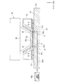
上述の各実施形態においては、液浸部材4に第2供給口42が配置される場合を例にして説明したが、第5実施形態の特徴的な部分は、液浸部材4Jの下面21と対向する位置に配置される所定部材に第2供給口42Jを設ける点にある。   In each of the above-described embodiments, the case where the second supply port 42 is disposed in the liquid immersion member 4 has been described as an example. However, a characteristic part of the fifth embodiment is that the lower surface 21 of the liquid immersion member 4J The second supply port 42J is provided in a predetermined member arranged at an opposing position.

図17は、第5実施形態に係る露光装置EXの一例を示す図である。図17において、計測ステージ2Jは、上面14に配置された第2供給口42Jを備えている。第2供給口42Jは、液浸部材4Jの下面21と対向可能である。第2供給口42Jは、流路45Jを介して、第2供給装置46Jと接続されている。流路45Jは、計測ステージ2Jの内部に形成された供給流路、及びその供給流路と第2供給装置46Jとを接続する供給管で形成される流路を含む。   FIG. 17 is a view showing an example of an exposure apparatus EX according to the fifth embodiment. In FIG. 17, the measurement stage 2J includes a second supply port 42J disposed on the upper surface 14. The second supply port 42J can face the lower surface 21 of the liquid immersion member 4J. The second supply port 42J is connected to the second supply device 46J through the flow path 45J. The channel 45J includes a supply channel formed inside the measurement stage 2J and a channel formed by a supply pipe that connects the supply channel and the second supply device 46J.

本実施形態において、防止装置53Jは、上述の第2実施形態で説明したような、開口24を閉じるためのカバー部材70と、そのカバー部材70をリリース可能に保持する保持装置71とを含む。なお、本実施形態においても、上述の第1実施形態のように第1供給口41から第1液体LQを流したり、上述の第3実施形態のように終端光学素子19の下方にシャッタ部材を配置したり、第4実施形態のように終端光学素子19の下方に流体カーテンを設けたりしてもよい。   In the present embodiment, the prevention device 53J includes a cover member 70 for closing the opening 24 and a holding device 71 that holds the cover member 70 so as to be releasable as described in the second embodiment. Also in this embodiment, the first liquid LQ is allowed to flow from the first supply port 41 as in the above-described first embodiment, or a shutter member is provided below the last optical element 19 as in the above-described third embodiment. Alternatively, a fluid curtain may be provided below the last optical element 19 as in the fourth embodiment.

制御装置5は、液浸部材4Jの下面21と計測ステージ2Jの上面14に配置された第2供給口42Jとを対向させた状態で、第2供給口42Jを用いる第2液体LCの供給動作と並行して、液浸部材4Jに配置されている液体回収口47Jを用いる第2液体LCの回収動作を実行することによって、液浸部材4Jの下面21及び計測ステージ2Jの上面14などをクリーニングすることができる。   The control device 5 supplies the second liquid LC using the second supply port 42J in a state where the lower surface 21 of the liquid immersion member 4J and the second supply port 42J disposed on the upper surface 14 of the measurement stage 2J are opposed to each other. In parallel with this, by performing the recovery operation of the second liquid LC using the liquid recovery port 47J disposed in the liquid immersion member 4J, the lower surface 21 of the liquid immersion member 4J, the upper surface 14 of the measurement stage 2J, and the like are cleaned. can do.

なお、本実施形態においては、計測ステージ2Jに第2供給口42Jが配置される場合を例にして説明したが、基板ステージ1に第2供給口が配置されてもよい。液浸部材の下面21と基板ステージ1の上面13に配置された第2供給口とを対向させた状態で、第2供給口を用いる第2液体LCの供給動作と並行して、液体回収口を用いる第2液体LCの回収動作を実行することによって、液浸部材の下面21及び基板ステージ1の上面13などをクリーニングできる。   In the present embodiment, the case where the second supply port 42J is arranged in the measurement stage 2J has been described as an example, but the second supply port may be arranged in the substrate stage 1. In a state where the lower surface 21 of the liquid immersion member and the second supply port arranged on the upper surface 13 of the substrate stage 1 are opposed to each other, a liquid recovery port is provided in parallel with the supply operation of the second liquid LC using the second supply port. By performing the recovery operation of the second liquid LC using the liquid, it is possible to clean the lower surface 21 of the liquid immersion member, the upper surface 13 of the substrate stage 1, and the like.

また、本実施形態において、液浸部材4Jにも第2液体LCを供給する第2供給口を設けておき、液浸部材4Jの第2供給口、および液浸部材4Jの下面21と対向する位置に配置される所定部材(計測ステージ2など)の第2供給口42Jとを併用してもよい。   In the present embodiment, the liquid supply member 4J is also provided with a second supply port for supplying the second liquid LC, and faces the second supply port of the liquid immersion member 4J and the lower surface 21 of the liquid immersion member 4J. You may use together with the 2nd supply port 42J of the predetermined member (measurement stage 2 etc.) arrange | positioned in a position.

なお、上述の第1〜第5実施形態において、液体回収口47(液体回収面33)とともに、あるいは液体回収口47(液体回収面33)を使わずに、液浸部材の下面と対向する位置に配置された液体回収部を使って、第1液体LQ及び/又は第2液体LCを回収するようにしてもよい。液浸部材の下面と対向する位置に配置された液体回収部は、例えば、基板ステージ1及び/又は計測ステージ2に設けることができる。   In the first to fifth embodiments described above, the position facing the lower surface of the liquid immersion member together with the liquid recovery port 47 (liquid recovery surface 33) or without using the liquid recovery port 47 (liquid recovery surface 33). The first liquid LQ and / or the second liquid LC may be recovered using the liquid recovery unit disposed in the. The liquid recovery part disposed at a position facing the lower surface of the liquid immersion member can be provided in the substrate stage 1 and / or the measurement stage 2, for example.

なお、上述の第1〜第5実施形態においては、液浸部材4の下面21と対向する位置に所定部材(基板ステージ1、計測ステージ2、ダミー基板DP)を配置し、液浸部材4の下面21と所定部材との間に第2液体LCを供給して、第2液体LCで液浸空間を形成する場合を例にして説明したが、上述のように、液浸部材の下面と対向する位置に液体回収部を配置する場合には、例えば開口24をカバー部材70で閉じた状態で、液浸部材4の下方から液浸部材4の下面に向けて第2液体LCを吹き付けてもよい。また、上述のように、液浸部材の下面と対向する位置に液体回収部を配置する場合には、例えば液浸部材の液体回収口47から第2液体LCを供給してもよい。   In the first to fifth embodiments described above, predetermined members (substrate stage 1, measurement stage 2, dummy substrate DP) are disposed at positions facing the lower surface 21 of the liquid immersion member 4. Although the case where the second liquid LC is supplied between the lower surface 21 and the predetermined member and the immersion space is formed by the second liquid LC has been described as an example, as described above, it faces the lower surface of the immersion member. In the case where the liquid recovery unit is disposed at a position where the liquid is to be discharged, the second liquid LC may be sprayed from below the liquid immersion member 4 toward the lower surface of the liquid immersion member 4 with the opening 24 closed by the cover member 70, for example. Good. Further, as described above, when the liquid recovery unit is disposed at a position facing the lower surface of the liquid immersion member, for example, the second liquid LC may be supplied from the liquid recovery port 47 of the liquid immersion member.

なお、上述の実施形態においては、アンモニアを含む第2液体LCを用いているが、これに限られず、コリン、水酸化ナトリウム(NaOH)、水酸化カリウム(KOH)、テトラメチルアンモニウムヒドロキシドの少なくとも1つを含む第2液体LCを用いてもよい。   In the above-described embodiment, the second liquid LC containing ammonia is used. However, the present invention is not limited to this. At least one of choline, sodium hydroxide (NaOH), potassium hydroxide (KOH), and tetramethylammonium hydroxide is used. A second liquid LC containing one may be used.

また、上述の各実施形態において、第2液体LCに振動(超音波)を与える超音波クリーニングを併用してもよい。   In each of the above-described embodiments, ultrasonic cleaning that applies vibration (ultrasonic waves) to the second liquid LC may be used in combination.

なお、上述の各実施形態において、液浸部材4は終端光学素子19に対して可動であってもよい。また、上述の各実施形態において、液浸部材4が複数の部材に分割されていてもよい。   In each of the above-described embodiments, the liquid immersion member 4 may be movable with respect to the last optical element 19. Further, in each of the above-described embodiments, the liquid immersion member 4 may be divided into a plurality of members.

なお、上述の各実施形態における投影光学系PLにおいて、終端光学素子19の射出側(像面側)の光路が第1液体LQで満たされているが、投影光学系PLとして、国際公開第2004/019128号パンフレットに開示されているような、終端光学素子19の入射側(物体面側)の光路も液体で満たされる投影光学系を採用することもできる。   In the projection optical system PL in each of the above-described embodiments, the optical path on the exit side (image plane side) of the last optical element 19 is filled with the first liquid LQ. A projection optical system in which the optical path on the incident side (object plane side) of the last optical element 19 is also filled with liquid as disclosed in the / 019128 pamphlet can be adopted.

なお、上述の各実施形態の第1液体LQは水であるが、水以外の液体であってもよい。例えば、第1液体LQとして、ハイドロフロロエーテル(HFE)、過フッ化ポリエーテル(PFPE)、フォンブリンオイル等を用いることも可能である。また、第1液体LQとして、種々の流体、例えば、超臨界流体を用いることも可能である。   In addition, although the 1st liquid LQ of each above-mentioned embodiment is water, liquids other than water may be sufficient. For example, hydrofluoroether (HFE), perfluorinated polyether (PFPE), fomblin oil, or the like can be used as the first liquid LQ. In addition, various fluids such as a supercritical fluid can be used as the first liquid LQ.

なお、上述の各実施形態の基板Pとしては、半導体デバイス製造用の半導体ウエハのみならず、ディスプレイデバイス用のガラス基板、薄膜磁気ヘッド用のセラミックウエハ、あるいは露光装置で用いられるマスクまたはレチクルの原版(合成石英、シリコンウエハ)等が適用される。   As the substrate P in each of the above embodiments, not only a semiconductor wafer for manufacturing a semiconductor device, but also a glass substrate for a display device, a ceramic wafer for a thin film magnetic head, or an original mask or reticle used in an exposure apparatus. (Synthetic quartz, silicon wafer) or the like is applied.

露光装置EXとしては、マスクMと基板Pとを同期移動してマスクMのパターンを走査露光するステップ・アンド・スキャン方式の走査型露光装置(スキャニングステッパ)の他に、マスクMと基板Pとを静止した状態でマスクMのパターンを一括露光し、基板Pを順次ステップ移動させるステップ・アンド・リピート方式の投影露光装置(ステッパ)にも適用することができる。   As the exposure apparatus EX, in addition to the step-and-scan type scanning exposure apparatus (scanning stepper) that scans and exposes the pattern of the mask M by moving the mask M and the substrate P synchronously, the mask M and the substrate P Can be applied to a step-and-repeat type projection exposure apparatus (stepper) in which the pattern of the mask M is collectively exposed while the substrate P is stationary and the substrate P is sequentially moved stepwise.

さらに、ステップ・アンド・リピート方式の露光において、第1パターンと基板Pとをほぼ静止した状態で、投影光学系PLを用いて第1パターンの縮小像を基板P上に転写した後、第2パターンと基板Pとをほぼ静止した状態で、投影光学系PLを用いて第2パターンの縮小像を第1パターンと部分的に重ねて基板P上に一括露光してもよい(スティッチ方式の一括露光装置)。また、スティッチ方式の露光装置としては、基板P上で少なくとも2つのパターンを部分的に重ねて転写し、基板Pを順次移動させるステップ・アンド・スティッチ方式の露光装置にも適用できる。   Furthermore, in the step-and-repeat exposure, after the reduced image of the first pattern is transferred onto the substrate P using the projection optical system PL while the first pattern and the substrate P are substantially stationary, the second pattern In a state where the pattern and the substrate P are substantially stationary, a reduced image of the second pattern may be partially overlapped with the first pattern using the projection optical system PL and may be collectively exposed on the substrate P (stitch-type batch). Exposure equipment). Further, the stitch type exposure apparatus can be applied to a step-and-stitch type exposure apparatus in which at least two patterns are partially transferred on the substrate P, and the substrate P is sequentially moved.

また、例えば米国特許第6611316号明細書に開示されているように、2つのマスクのパターンを、投影光学系を介して基板上で合成し、1回の走査露光によって基板上の1つのショット領域をほぼ同時に二重露光する露光装置などにも本発明を適用することができる。また、プロキシミティ方式の露光装置、ミラープロジェクション・アライナーなどにも本発明を適用することができる。   Further, as disclosed in, for example, US Pat. No. 6,611,316, two mask patterns are synthesized on a substrate via a projection optical system, and one shot area on the substrate is obtained by one scanning exposure. The present invention can also be applied to an exposure apparatus that performs double exposure almost simultaneously. The present invention can also be applied to proximity type exposure apparatuses, mirror projection aligners, and the like.

また、本発明は、米国特許第6341007号明細書、米国特許第6208407号明細書、米国特許第6262796号明細書等に開示されているような複数の基板ステージを備えたツインステージ型の露光装置にも適用できる。   The present invention also relates to a twin stage type exposure apparatus having a plurality of substrate stages as disclosed in US Pat. No. 6,341,007, US Pat. No. 6,208,407, US Pat. No. 6,262,796, and the like. It can also be applied to.

露光装置EXの種類としては、基板Pに半導体素子パターンを露光する半導体素子製造用の露光装置に限られず、液晶表示素子製造用又はディスプレイ製造用の露光装置や、薄膜磁気ヘッド、撮像素子(CCD)、マイクロマシン、MEMS、DNAチップ、あるいはレチクル又はマスクなどを製造するための露光装置などにも広く適用できる。   The type of the exposure apparatus EX is not limited to an exposure apparatus for manufacturing a semiconductor element that exposes a semiconductor element pattern onto the substrate P, but an exposure apparatus for manufacturing a liquid crystal display element or a display, a thin film magnetic head, an image sensor (CCD). ), An exposure apparatus for manufacturing a micromachine, a MEMS, a DNA chip, a reticle, a mask, or the like.

なお、上述の各実施形態においては、レーザ干渉計を含む干渉計システムを用いてマスクステージ1及び基板ステージ2の各位置情報を計測するものとしたが、これに限らず、例えば各ステージ1、2に設けられるスケール(回折格子)を検出するエンコーダシステムを用いてもよい。この場合、干渉計システムとエンコーダシステムとの両方を備えるハイブリッドシステムとしてもよい。   In each of the above-described embodiments, the positional information of the mask stage 1 and the substrate stage 2 is measured using an interferometer system including a laser interferometer. An encoder system for detecting a scale (diffraction grating) provided in 2 may be used. In this case, it is good also as a hybrid system provided with both an interferometer system and an encoder system.

また、上述の各実施形態では、露光光ELとしてArFエキシマレーザ光を発生する光源装置として、ArFエキシマレーザを用いてもよいが、例えば、米国特許第7023610号明細書に開示されているように、DFB半導体レーザ又はファイバーレーザなどの固体レーザ光源、ファイバーアンプなどを有する光増幅部、及び波長変換部などを含み、波長193nmのパルス光を出力する高調波発生装置を用いてもよい。さらに、上記実施形態では、前述の各照明領域と、投影領域がそれぞれ矩形状であるものとしたが、他の形状、例えば円弧状などでもよい。   In each of the above embodiments, an ArF excimer laser may be used as a light source device that generates ArF excimer laser light as the exposure light EL. For example, as disclosed in US Pat. No. 7,023,610. A harmonic generator that outputs pulsed light with a wavelength of 193 nm may be used, including a solid-state laser light source such as a DFB semiconductor laser or a fiber laser, an optical amplification unit having a fiber amplifier, a wavelength conversion unit, and the like. Furthermore, in the above-described embodiment, each illumination area and the projection area described above are rectangular, but other shapes such as an arc shape may be used.

なお、上述の各実施形態においては、光透過性の基板上に所定の遮光パターン(又は位相パターン・減光パターン)を形成した光透過型マスクを用いたが、このマスクに代えて、例えば米国特許第6778257号明細書に開示されているように、露光すべきパターンの電子データに基づいて透過パターン又は反射パターン、あるいは発光パターンを形成する可変成形マスク(電子マスク、アクティブマスク、あるいはイメージジェネレータとも呼ばれる)を用いてもよい。可変成形マスクは、例えば非発光型画像表示素子(空間光変調器)の一種であるDMD(Digital Micro-mirror Device)等を含む。また、非発光型画像表示素子を備える可変成形マスクに代えて、自発光型画像表示素子を含むパターン形成装置を備えるようにしても良い。自発光型画像表示素子としては、例えば、CRT(Cathode Ray Tube)、無機ELディスプレイ、有機ELディスプレイ(OLED:Organic Light Emitting Diode)、LEDディスプレイ、LDディスプレイ、電界放出ディスプレイ(FED:Field Emission Display)、プラズマディスプレイ(PDP:Plasma Display Panel)等が挙げられる。   In each of the above-described embodiments, a light-transmitting mask in which a predetermined light-shielding pattern (or phase pattern / dimming pattern) is formed on a light-transmitting substrate is used. As disclosed in Japanese Patent No. 6778257, a variable shaped mask (also known as an electronic mask, an active mask, or an image generator) that forms a transmission pattern, a reflection pattern, or a light emission pattern based on electronic data of a pattern to be exposed. May be used). The variable shaping mask includes, for example, a DMD (Digital Micro-mirror Device) which is a kind of non-light emitting image display element (spatial light modulator). Further, a pattern forming apparatus including a self-luminous image display element may be provided instead of the variable molding mask including the non-luminous image display element. As a self-luminous type image display element, for example, CRT (Cathode Ray Tube), inorganic EL display, organic EL display (OLED: Organic Light Emitting Diode), LED display, LD display, field emission display (FED: Field Emission Display) And a plasma display panel (PDP).

上述の各実施形態においては、投影光学系PLを備えた露光装置を例に挙げて説明してきたが、投影光学系PLを用いない露光装置及び露光方法に本発明を適用することができる。このように投影光学系PLを用いない場合であっても、露光光はレンズ等の光学部材を介して基板に照射され、そのような光学部材と基板との間の所定空間に液浸空間が形成される。   In each of the above embodiments, the exposure apparatus provided with the projection optical system PL has been described as an example, but the present invention can be applied to an exposure apparatus and an exposure method that do not use the projection optical system PL. Even when the projection optical system PL is not used in this way, the exposure light is irradiated onto the substrate via an optical member such as a lens, and an immersion space is formed in a predetermined space between the optical member and the substrate. It is formed.

また、例えば国際公開第2001/035168号パンフレットに開示されているように、干渉縞を基板P上に形成することによって、基板P上にライン・アンド・スペースパターンを露光する露光装置(リソグラフィシステム)にも本発明を適用することができる。   Further, as disclosed in, for example, International Publication No. 2001/035168, an exposure apparatus (lithography system) that exposes a line and space pattern on the substrate P by forming interference fringes on the substrate P. The present invention can also be applied to.

以上のように、本実施形態の露光装置EXは、本願請求の範囲に挙げられた各構成要素を含む各種サブシステムを、所定の機械的精度、電気的精度、光学的精度を保つように、組み立てることで製造される。これら各種精度を確保するために、この組み立ての前後には、各種光学系については光学的精度を達成するための調整、各種機械系については機械的精度を達成するための調整、各種電気系については電気的精度を達成するための調整が行われる。各種サブシステムから露光装置への組み立て工程は、各種サブシステム相互の、機械的接続、電気回路の配線接続、気圧回路の配管接続等が含まれる。この各種サブシステムから露光装置への組み立て工程の前に、各サブシステム個々の組み立て工程があることはいうまでもない。各種サブシステムの露光装置への組み立て工程が終了したら、総合調整が行われ、露光装置全体としての各種精度が確保される。なお、露光装置の製造は温度およびクリーン度等が管理されたクリーンルームで行うことが望ましい。   As described above, the exposure apparatus EX of the present embodiment maintains various mechanical subsystems including the respective constituent elements recited in the claims of the present application so as to maintain predetermined mechanical accuracy, electrical accuracy, and optical accuracy. Manufactured by assembling. In order to ensure these various accuracies, before and after assembly, various optical systems are adjusted to achieve optical accuracy, various mechanical systems are adjusted to achieve mechanical accuracy, and various electrical systems are Adjustments are made to achieve electrical accuracy. The assembly process from the various subsystems to the exposure apparatus includes mechanical connection, electrical circuit wiring connection, pneumatic circuit piping connection and the like between the various subsystems. Needless to say, there is an assembly process for each subsystem before the assembly process from the various subsystems to the exposure apparatus. When the assembly process of the various subsystems to the exposure apparatus is completed, comprehensive adjustment is performed to ensure various accuracies as the entire exposure apparatus. The exposure apparatus is preferably manufactured in a clean room where the temperature, cleanliness, etc. are controlled.

半導体デバイス等のマイクロデバイスは、図18に示すように、マイクロデバイスの機能・性能設計を行うステップ201、この設計ステップに基づいたマスク(レチクル)を製作するステップ202、デバイスの基材である基板を製造するステップ203、上述の実施形態に従って、マスクのパターンを用いて露光光で基板を露光すること、及び露光された基板を現像することを含む基板処理(露光処理)を含む基板処理ステップ204、デバイス組み立てステップ(ダイシング工程、ボンディング工程、パッケージ工程などの加工プロセスを含む)205、検査ステップ206等を経て製造される。   As shown in FIG. 18, a microdevice such as a semiconductor device includes a step 201 for designing the function and performance of the microdevice, a step 202 for producing a mask (reticle) based on the design step, and a substrate which is a base material of the device. Substrate processing step 204 including substrate processing (exposure processing) including exposing the substrate with exposure light using a mask pattern and developing the exposed substrate according to the above-described embodiment. The device is manufactured through a device assembly step (including processing processes such as a dicing process, a bonding process, and a package process) 205, an inspection step 206, and the like.

なお、上述の各実施形態の要件は、適宜組み合わせることができる。また、一部の構成要素を用いない場合もある。また、法令で許容される限りにおいて、上述の各実施形態及び変形例で引用した露光装置などに関する全ての公開公報及び米国特許の開示を援用して本文の記載の一部とする。   Note that the requirements of the above-described embodiments can be combined as appropriate. Some components may not be used. In addition, as long as permitted by law, the disclosure of all published publications and US patents related to the exposure apparatus and the like cited in the above-described embodiments and modifications are incorporated herein by reference.

1…基板ステージ、2…計測ステージ、4…液浸部材、19…終端光学素子、20…射出面、21…下面、23…第2プレート部、24…開口、26…上側空間、28…下側空間、33…平坦面、41…第1供給口、42…第2供給口、47…液体回収口、53…防止装置、70…カバー部材、71…保持装置、77…流体カーテン、DP…ダミー基板、EL…露光光、EX…露光装置、LC…クリーニング液体、LQ…露光液体、P…基板   DESCRIPTION OF SYMBOLS 1 ... Substrate stage, 2 ... Measurement stage, 4 ... Liquid immersion member, 19 ... End optical element, 20 ... Ejection surface, 21 ... Lower surface, 23 ... 2nd plate part, 24 ... Opening, 26 ... Upper space, 28 ... Bottom Side space 33 ... Flat surface 41 ... First supply port 42 ... Second supply port 47 ... Liquid recovery port 53 ... Prevention device 70 ... Cover member 71 ... Holding device 77 ... Fluid curtain DP ... Dummy substrate, EL ... exposure light, EX ... exposure device, LC ... cleaning liquid, LQ ... exposure liquid, P ... substrate

Claims (40)

露光液体を介して露光光で基板を露光する露光装置であって、
前記露光光を射出する射出面を有する光学部材と、
前記露光液体を供給する第1供給口と、
前記光学部材から射出される前記露光光の光路が前記露光液体で満たされるように液浸空間を形成可能な液浸部材と、
前記液浸部材と接触するようにクリーニング液体を供給する第2供給口と、
前記クリーニング液体と前記光学部材との接触を防止する防止装置と、を備えた露光装置。
An exposure apparatus that exposes a substrate with exposure light through an exposure liquid,
An optical member having an exit surface for emitting the exposure light;
A first supply port for supplying the exposure liquid;
An immersion member capable of forming an immersion space so that an optical path of the exposure light emitted from the optical member is filled with the exposure liquid;
A second supply port for supplying a cleaning liquid so as to come into contact with the liquid immersion member;
An exposure apparatus comprising: a prevention device that prevents contact between the cleaning liquid and the optical member.
前記液浸部材は、前記射出面から射出された前記露光光が通過可能な開口を有するプレート部を備え、
前記クリーニング液体は、前記開口の下側の空間に供給され、
前記防止装置は、前記開口を介して、前記クリーニング液体が前記開口の上側の空間へ流入することを防止する請求項1記載の露光装置。
The liquid immersion member includes a plate portion having an opening through which the exposure light emitted from the emission surface can pass.
The cleaning liquid is supplied to a space below the opening;
The exposure apparatus according to claim 1, wherein the prevention device prevents the cleaning liquid from flowing into a space above the opening through the opening.
前記防止装置は、前記開口を閉じるためのカバー部材を含む請求項2記載の露光装置。   The exposure apparatus according to claim 2, wherein the prevention device includes a cover member for closing the opening. 前記防止装置は、前記開口を前記カバー部材で閉じるために、前記カバー部材をリリース可能に保持する保持装置を含む請求項3記載の露光装置。   4. The exposure apparatus according to claim 3, wherein the prevention device includes a holding device that releasably holds the cover member in order to close the opening with the cover member. 前記保持装置の少なくとも一部は、前記液浸部材に設けられる請求項4記載の露光装置。   The exposure apparatus according to claim 4, wherein at least a part of the holding device is provided on the liquid immersion member. 前記防止装置は、前記開口の近傍で、流体カーテンを形成する請求項2〜5のいずれか一項記載の露光装置。   The exposure apparatus according to claim 2, wherein the prevention device forms a fluid curtain in the vicinity of the opening. 前記流体カーテンは、前記開口の一方側から他方側へ向けて前記流体を流すことによって形成される請求項6記載の露光装置。   The exposure apparatus according to claim 6, wherein the fluid curtain is formed by flowing the fluid from one side of the opening toward the other side. 前記流体は、気体を含む請求項6又は7記載の露光装置。   The exposure apparatus according to claim 6, wherein the fluid includes a gas. 前記防止装置は、前記第1供給口を含み、前記第1供給口から前記上側の空間に、前記露光液体を供給することによって前記クリーニング液体が前記上側の空間へ流入することを防止する請求項2記載の露光装置。   The prevention device includes the first supply port, and prevents the cleaning liquid from flowing into the upper space by supplying the exposure liquid from the first supply port to the upper space. 2. The exposure apparatus according to 2. 前記プレート部は、前記開口の周囲に配置され、前記開口の下側の空間に面する平坦面を含み、
前記第2供給口は、前記開口に対して前記平坦面の外側に配置される請求項9記載の露光装置。
The plate portion is disposed around the opening and includes a flat surface facing a space below the opening;
The exposure apparatus according to claim 9, wherein the second supply port is disposed outside the flat surface with respect to the opening.
前記防止装置は、前記第1供給口を含み、前記第1供給口から前記露光液体を供給することによって前記クリーニング液体が前記光学部材に接触することを防止する請求項1又は2記載の露光装置。   The exposure apparatus according to claim 1, wherein the prevention device includes the first supply port, and prevents the cleaning liquid from contacting the optical member by supplying the exposure liquid from the first supply port. . 前記第1供給口は、前記第2供給口より前記光学部材の近くに配置されている請求項11記載の露光装置。   The exposure apparatus according to claim 11, wherein the first supply port is disposed closer to the optical member than the second supply port. 前記第1供給口は、前記第2供給口より上方に配置されている請求項11又は12記載の露光装置。   The exposure apparatus according to claim 11 or 12, wherein the first supply port is disposed above the second supply port. 前記クリーニング液体は、前記液浸部材と所定部材との間の空間に供給される請求項2〜13のいずれか一項記載の露光装置。   The exposure apparatus according to claim 2, wherein the cleaning liquid is supplied to a space between the liquid immersion member and a predetermined member. 前記クリーニング液体は、前記液浸部材と所定部材との間の空間に供給される請求項1記載の露光装置。   The exposure apparatus according to claim 1, wherein the cleaning liquid is supplied to a space between the liquid immersion member and a predetermined member. 前記防止装置は、前記光学部材と前記所定部材との間にバリアを設けることによって、前記クリーニング液体と前記光学部材との接触を防止する請求項15記載の露光装置。   16. The exposure apparatus according to claim 15, wherein the prevention device prevents contact between the cleaning liquid and the optical member by providing a barrier between the optical member and the predetermined member. 前記バリアは、前記光学部材と前記所定部材との間に配置されるカバー部材を含む請求項16記載の露光装置。   The exposure apparatus according to claim 16, wherein the barrier includes a cover member disposed between the optical member and the predetermined member. 前記防止装置は、前記カバー部材をリリース可能に保持する保持装置を含む請求項17記載の露光装置。   The exposure apparatus according to claim 17, wherein the prevention device includes a holding device that holds the cover member in a releasable manner. 前記保持装置の少なくとも一部は、前記液浸部材に設けられる請求項18記載の露光装置。   The exposure apparatus according to claim 18, wherein at least a part of the holding device is provided on the liquid immersion member. 前記バリアは、流体カーテンを含む請求項16〜19のいずれか一項記載の露光装置。   The exposure apparatus according to claim 16, wherein the barrier includes a fluid curtain. 前記流体は、気体を含む請求項20記載の露光装置。   The exposure apparatus according to claim 20, wherein the fluid includes a gas. 前記所定部材は、前記液浸部材に対して可動である請求項14〜21のいずれか一項記載の露光装置。   The exposure apparatus according to any one of claims 14 to 21, wherein the predetermined member is movable with respect to the liquid immersion member. 前記液浸部材に対して可動なステージをさらに備え、
前記所定部材は、前記ステージの一部を含む請求項22記載の露光装置。
A stage movable with respect to the liquid immersion member;
The exposure apparatus according to claim 22, wherein the predetermined member includes a part of the stage.
前記ステージは、前記基板を保持する基板ステージを含む請求項23記載の露光装置。   The exposure apparatus according to claim 23, wherein the stage includes a substrate stage for holding the substrate. 前記ステージは、少なくとも1つの計測器を搭載した計測ステージを含む請求項23又は24記載の露光装置。   The exposure apparatus according to claim 23 or 24, wherein the stage includes a measurement stage on which at least one measuring instrument is mounted. 前記第2供給口は、前記ステージに設けられる請求項23〜25のいずれか一項記載の露光装置。   The exposure apparatus according to any one of claims 23 to 25, wherein the second supply port is provided in the stage. 前記クリーニング液体によって、前記所定部材をクリーニングする請求項14〜26のいずれか一項記載の露光装置。   27. The exposure apparatus according to claim 14, wherein the predetermined member is cleaned with the cleaning liquid. 前記第2供給口は、前記液浸部材に配置され、
前記所定部材は、前記第2供給口と対向するように配置される請求項27記載の露光装置。
The second supply port is disposed in the liquid immersion member,
28. The exposure apparatus according to claim 27, wherein the predetermined member is disposed so as to face the second supply port.
前記第2供給口は、前記液浸部材に配置される請求項1〜28のいずれか一項記載の露光装置。   The exposure apparatus according to claim 1, wherein the second supply port is disposed in the liquid immersion member. 前記クリーニング液体によって、前記液浸部材をクリーニングする請求項1〜29のいずれか一項記載の露光装置。   30. The exposure apparatus according to claim 1, wherein the liquid immersion member is cleaned with the cleaning liquid. 前記第1供給口は、前記液浸部材に配置される請求項1〜30のいずれか一項記載の露光装置。   The exposure apparatus according to claim 1, wherein the first supply port is disposed in the liquid immersion member. 前記クリーニング液体は、アルカリを含む請求項1〜31のいずれか一項記載の露光装置。   The exposure apparatus according to claim 1, wherein the cleaning liquid contains an alkali. 前記露光液体及び前記クリーニング液体の少なくとも一方を回収可能な液体回収口を含む請求項1〜32のいずれか一項記載の露光装置。   The exposure apparatus according to claim 1, further comprising a liquid recovery port capable of recovering at least one of the exposure liquid and the cleaning liquid. 請求項1〜33のいずれか一項記載の露光装置を用いて基板を露光することと、
露光された基板を現像することと、を含むデバイス製造方法。
Exposing the substrate using the exposure apparatus according to any one of claims 1 to 33;
Developing the exposed substrate; and a device manufacturing method.
光学部材から射出された露光光で露光液体を介して基板を露光する露光装置のクリーニング方法であって、
前記光学部材から射出される前記露光光の光路が前記露光液体で満たされるように液浸空間を形成可能な液浸部材と対向するように所定部材を配置することと、
前記液浸部材と前記所定部材との間の空間にクリーニング液体を供給することと、を含み、
前記クリーニング液体の供給が、前記クリーニング液体と前記光学部材との接触を防止しながら行われるクリーニング方法。
An exposure apparatus cleaning method for exposing a substrate through exposure liquid with exposure light emitted from an optical member,
Disposing a predetermined member to face an immersion member capable of forming an immersion space so that an optical path of the exposure light emitted from the optical member is filled with the exposure liquid;
Supplying a cleaning liquid to a space between the liquid immersion member and the predetermined member,
A cleaning method in which the supply of the cleaning liquid is performed while preventing contact between the cleaning liquid and the optical member.
前記所定部材は、前記液浸部材に対して移動可能な可動部材を含む請求項35記載のクリーニング方法。   36. The cleaning method according to claim 35, wherein the predetermined member includes a movable member movable with respect to the liquid immersion member. 前記露光装置は、前記基板をリリース可能に保持する基板保持部を有し、
前記所定部材は、前記基板保持部に保持されたダミー基板を含む請求項36記載のクリーニング方法。
The exposure apparatus includes a substrate holding unit that holds the substrate in a releasable manner,
37. The cleaning method according to claim 36, wherein the predetermined member includes a dummy substrate held by the substrate holding part.
前記クリーニング液体の供給を停止することと、
基板の露光前に、前記所定部材から前記クリーニング液体を除去することと、をさらに含む請求項35〜37のいずれか一項記載のクリーニング方法。
Stopping the supply of the cleaning liquid;
38. The cleaning method according to claim 35, further comprising removing the cleaning liquid from the predetermined member before exposing the substrate.
前記クリーニング液体の除去は、前記露光液体の供給を含む請求項38記載のクリーニング方法。   The cleaning method according to claim 38, wherein the removal of the cleaning liquid includes supply of the exposure liquid. 露光液体を介して露光光で基板を露光する露光装置を請求項35〜39のいずれか一項記載のクリーニング方法でクリーニングすることと、
前記クリーニング後に、前記露光装置で前記基板を露光することと、
露光された前記基板を現像することと、を含むデバイス製造方法。
Cleaning an exposure apparatus that exposes a substrate with exposure light through an exposure liquid by the cleaning method according to any one of claims 35 to 39;
After the cleaning, exposing the substrate with the exposure apparatus;
Developing the exposed substrate. A device manufacturing method.
JP2009097045A 2008-04-14 2009-04-13 Exposure apparatus, cleaning method, and device manufacturing method Withdrawn JP2009260352A (en)

Applications Claiming Priority (1)

Application Number Priority Date Filing Date Title
US7113208P 2008-04-14 2008-04-14

Publications (2)

Publication Number Publication Date
JP2009260352A true JP2009260352A (en) 2009-11-05
JP2009260352A5 JP2009260352A5 (en) 2013-07-18

Family

ID=41387282

Family Applications (1)

Application Number Title Priority Date Filing Date
JP2009097045A Withdrawn JP2009260352A (en) 2008-04-14 2009-04-13 Exposure apparatus, cleaning method, and device manufacturing method

Country Status (1)

Country Link
JP (1) JP2009260352A (en)

Cited By (3)

* Cited by examiner, † Cited by third party
Publication number Priority date Publication date Assignee Title
JP2009267404A (en) * 2008-04-24 2009-11-12 Asml Netherlands Bv Lithographic apparatus and method of operating the apparatus
WO2011125977A1 (en) * 2010-04-02 2011-10-13 株式会社ニコン Cleaning method, device manufacturing method, exposure apparatus, and device manufacturing system
US9261796B2 (en) 2009-12-02 2016-02-16 Asml Netherlands B.V. Lithographic apparatus and surface cleaning method

Cited By (9)

* Cited by examiner, † Cited by third party
Publication number Priority date Publication date Assignee Title
JP2009267404A (en) * 2008-04-24 2009-11-12 Asml Netherlands Bv Lithographic apparatus and method of operating the apparatus
US8823918B2 (en) 2008-04-24 2014-09-02 Asml Netherlands B.V. Lithographic apparatus and a method of operating the apparatus
US10175585B2 (en) 2008-04-24 2019-01-08 Asml Netherlands B.V. Lithographic apparatus and a method of operating the apparatus
US9261796B2 (en) 2009-12-02 2016-02-16 Asml Netherlands B.V. Lithographic apparatus and surface cleaning method
US9645508B2 (en) 2009-12-02 2017-05-09 Asml Netherlands B.V. Lithographic apparatus and surface cleaning method
US9927716B2 (en) 2009-12-02 2018-03-27 Asml Netherlands B.V. Lithographic apparatus and surface cleaning method
US10185223B2 (en) 2009-12-02 2019-01-22 Asml Netherlands B.V. Lithographic apparatus and surface cleaning method
US10437156B2 (en) 2009-12-02 2019-10-08 Asml Netherlands B.V. Lithographic apparatus and surface cleaning method
WO2011125977A1 (en) * 2010-04-02 2011-10-13 株式会社ニコン Cleaning method, device manufacturing method, exposure apparatus, and device manufacturing system

Similar Documents

Publication Publication Date Title
US8035800B2 (en) Exposure apparatus, maintenance method, exposure method, and method for producing device
JPWO2010018825A1 (en) Exposure apparatus, maintenance method, and device manufacturing method
JP2012164996A (en) Cleaning member, cleaning method, and device manufacturing method
EP1901338A1 (en) Exposure apparatus and method, exposure apparatus maintenance method, and device manufacturing method
JP5152321B2 (en) Cleaning tool, cleaning method, and device manufacturing method
US8654306B2 (en) Exposure apparatus, cleaning method, and device fabricating method
JP2009021498A (en) Exposure device, liquid immersion system, and device manufacturing method
JP2009260352A (en) Exposure apparatus, cleaning method, and device manufacturing method
JP2009267401A (en) Exposure apparatus, cleaning method, and device fabricating method
JP2011165798A (en) Aligner, method used by the aligner, method of manufacturing device, program, and recording medium
JP2009188119A (en) Cover member, stepper, exposure method, and device manufacturing method
WO2013031928A1 (en) Exposure apparatus, liquid holding method, and device manufacturing method
JP2010177669A (en) Exposure apparatus, exposing method, liquid immersion member and device fabricating method
JP2010267656A (en) Exposure apparatus, exposure method, and device-manufacturing method
JP5018277B2 (en) Exposure apparatus, device manufacturing method, and cleaning method
WO2011046174A1 (en) Exposure apparatus, exposure method, maintenance method, and method for manufacturing device
JP2010157724A (en) Exposure apparatus, exposure method, and device manufacturing method
JP2010109271A (en) Confirmation method, maintenance method, and method of manufacturing device
JP2010157726A (en) Exposure apparatus, exposure method, and device manufacturing method
JP2010016264A (en) Exposure device, maintenance method, exposure method, and device manufacturing method
JP2009212132A (en) Substrate, method and apparatus of treating substrate, substrate treatment system, method and apparatus of lithography, and device manufacturing method
JP2010109270A (en) Confirmation method, maintenance method, and method of manufacturing device
JP2011029326A (en) Aligner, maintenance method, and method of fabricating device
JP2010267808A (en) Aligner, cleaning method, and method of manufacturing device
JP2009044089A (en) Exposure method, and device manufacturing method and system

Legal Events

Date Code Title Description
A621 Written request for application examination

Free format text: JAPANESE INTERMEDIATE CODE: A621

Effective date: 20120323

A521 Written amendment

Free format text: JAPANESE INTERMEDIATE CODE: A523

Effective date: 20130531

A761 Written withdrawal of application

Free format text: JAPANESE INTERMEDIATE CODE: A761

Effective date: 20130912

A977 Report on retrieval

Free format text: JAPANESE INTERMEDIATE CODE: A971007

Effective date: 20130926