KR101657994B1 - Form traveler, and bridge construction method for using the same - Google Patents
Form traveler, and bridge construction method for using the same Download PDFInfo
- Publication number
- KR101657994B1 KR101657994B1 KR1020140061781A KR20140061781A KR101657994B1 KR 101657994 B1 KR101657994 B1 KR 101657994B1 KR 1020140061781 A KR1020140061781 A KR 1020140061781A KR 20140061781 A KR20140061781 A KR 20140061781A KR 101657994 B1 KR101657994 B1 KR 101657994B1
- Authority
- KR
- South Korea
- Prior art keywords
- unit
- girder
- bridge
- frame
- rail
- Prior art date
Links
Images


Classifications
-
- E—FIXED CONSTRUCTIONS
- E01—CONSTRUCTION OF ROADS, RAILWAYS, OR BRIDGES
- E01D—CONSTRUCTION OF BRIDGES, ELEVATED ROADWAYS OR VIADUCTS; ASSEMBLY OF BRIDGES
- E01D21/00—Methods or apparatus specially adapted for erecting or assembling bridges
Landscapes
- Engineering & Computer Science (AREA)
- Architecture (AREA)
- Civil Engineering (AREA)
- Structural Engineering (AREA)
- Bridges Or Land Bridges (AREA)
Abstract
본 발명은 FCM(Free Cantilever Method)공법을 이용한 교량의 시공시 사용되는 폼 트래블러에 관한 것으로서,
교량 시공시 박스형 거더의 상면에 교량의 시공방향을 따라 설치되는 메인레일; 트러스 구조로 이루어지고, 상기 메인레일을 따라 이동 가능하게 설치된 프레임유닛; 거더의 내측에 배치되도록 상기 프레임유닛에 연결되고, 상기 프레임유닛과 함께 이동되는 내부거푸집유닛; 거더의 하측에 배치되는 외부거푸집유닛; 상기 프레임유닛에 결합된 서브레일; 및 상기 서브레일과 상기 외부거푸집유닛을 연결하고, 상기 서브레일을 따라 이동 가능하게 설치되는 중계유닛;을 포함하여 이루어진 폼 트래블러 및 이를 이용한 교량의 시공방법을 개시한다.
본 발명에 의하면, 내부거푸집유닛 및 외부거푸집유닛이 각각 메인레일 및 서브레일을 따라 상호 개별적으로 런칭됨으로써 교량 시공시 외부거푸집유닛만을 런칭한 상태에서 기 조립된 철근구조물을 용이하게 배치할 수 있으며, 이에 따라 공기(工期)를 단축할 수 있는 효과가 있다.BACKGROUND OF THE INVENTION Field of the Invention [0001] The present invention relates to a form traveler used in construction of a bridge using FCM (Free Cantilever Method)
A main rail installed on the upper surface of the box type girder along the installation direction of the bridge when the bridge is constructed; A frame unit made of a truss structure and movably provided along the main rail; An inner die unit connected to the frame unit so as to be disposed inside the girder and moved together with the frame unit; An outer die unit disposed on the lower side of the girder; A sub-rail coupled to the frame unit; And a relay unit connecting the sub rail and the outer die unit and being installed to be movable along the sub rail, and a method of constructing a bridge using the form traveler.
According to the present invention, since the inner form unit and the outer form unit are individually launched along the main rail and the sub rail, it is possible to easily arrange the pre-assembled reinforcing structure in a state where only the outer form unit is launched during the bridge construction, Thereby, the air (construction period) can be shortened.
Description
본 발명은 FCM(Free Cantilever Method)공법을 이용한 교량의 시공시 사용되는 폼 트래블러 및 이를 이용한 교량의 시공방법에 관한 것이다.
BACKGROUND OF THE INVENTION 1. Field of the Invention [0001] The present invention relates to a form traveler used in construction of a bridge using FCM (Free Cantilever Method) method and a method of constructing a bridge using the same.
폼 트래블러에 관한 기술로는 [대한민국 등록특허공보 제10-1259031호(2013.04.29.공고, 이하 '선행기술'이라고 함) "횡단 프레임을 구비한 폼 트래블러 및 그 런칭방법"]이 제시되어 있다.As a technique related to the form traveler, there is proposed a form traveler having a transverse frame and a method of launching it [Korean Patent Registration No. 10-1259031 (issued on March 29, 2013, hereinafter referred to as "prior art") .
상기 선행기술은The prior art
"시공구조물의 최선단에 설치되어 시공 구조물의 시공을 위한 거푸집설치 작업 및 콘크리트 타설 및 양생 작업을 위해 사용되는 폼 트래블러에 있어서,"A foam traveler installed at the foremost end of a construction structure to be used for installing a formwork for construction of a construction structure, and for concrete pouring and curing work,
미리 완성된 시공구조물의 최선단 상면에 설치된 메인 레일;A main rail installed on the topmost surface of the prefabricated construction structure;
상기 메인 레일 상면에 횡방향으로 연장되어 설치되는 횡방향 부재인 횡단 프레임;A transverse frame which is a transverse member extending laterally on an upper surface of the main rail;
상기 횡단 프레임 상면에 설치된 메인 프레임; 및A main frame installed on an upper surface of the transverse frame; And
상기 횡단 프레임 후방에서 메인 레일과 횡단 프레임 사이에 설치되어 폼 트래블러를 전방으로 이동시키기 위하여 설치된 유압실린더인 메인잭"을 포함하여 이루어진 것으로서,And a main jack, which is a hydraulic cylinder installed between the main rail and the transverse frame at the rear of the transverse frame to move the form traveler forward,
메인 프레임의 위치에 상관없이 폼 트래블러에 장착된 유압잭 및 메인 레일의 횡방향 위치를 조절할 수 있으며, 거더에 가해지는 하중을 분산시킬 수 있도록 한 기술이다.
It is possible to adjust the lateral position of the hydraulic jack and main rail mounted on the form traveler regardless of the position of the main frame, and to distribute the load applied to the girder.
한편, 상기 선행기술을 비롯한 종래의 폼 트래블러를 이용한 교량의 시공방법은, 폼 트래블러의 바닥 거푸집 및 내부 거푸집을 기 시공된 거더의 전방으로 런칭한 후 바닥 거푸집의 상부에 철근을 배치하고 콘크리트를 타설하는 과정으로 이루어진다.Meanwhile, in the conventional method of constructing a bridge using a form traveler, a floor traveler and an inner form of a form traveler are launched to the front of the installed girder, a reinforcing bar is disposed on the upper part of the floor formwork, .
그런데 상기 선행기술을 비롯한 종래의 폼 트래블러를 이용한 교량의 시공방법의 경우, 철근 배치과정에서 작업자가 바닥 거푸집 및 내부 거푸집 사이로 진입하여 철근을 거더의 형상에 상응하도록 일일 조립해야만 함으로써 철근 배치과정에서 많은 시간이 소요되는 문제가 있다.However, in the case of a conventional method of installing a bridge using a form traveler, the operator must enter the space between the bottom mold and the inner mold in the process of disposing the reinforcing bars, and the reinforcing bars must be assembled one by one corresponding to the shape of the girders. There is a time consuming problem.
즉, 미리 조립해둔 철근구조물을 사용할 경우 공기(工期)를 단축할 수 있겠으나, 이 경우 기 조립된 철근구조물을 바닥 거푸집 및 내부 거푸집 사이로 투입하기가 곤란한 문제가 있는 것이다.
That is, if the pre-assembled reinforced concrete structure is used, it is possible to shorten the air (construction period). However, in this case, it is difficult to insert the pre-assembled reinforced concrete structure between the floor formwork and the inner formwork.
본 발명은 상기와 같은 문제점을 해결하기 위하여 안출된 것으로서,SUMMARY OF THE INVENTION The present invention has been made to solve the above problems,
FCM공법을 이용한 교량의 시공시 기 조립된 철근조립체를 이용할 수 있도록 함으로써 철근배치작업이 신속하고 용이하게 이루어질 수 있으며, 이에 따라 공기(工期)를 단축할 수 있도록 한 폼 트래블러 및 이를 이용한 교량의 시공방법을 제공하는 것을 목적으로 한다.
By using the assembled steel reinforced assembly during the construction of the bridge using the FCM method, it is possible to quickly and easily arrange the reinforcing steel, and accordingly, it is possible to shorten the air (construction period) And a method thereof.
상기와 같은 과제를 해결하기 위하여 본 발명에 의한 폼 트래블러는,In order to solve the above problems, a form traveler according to the present invention comprises:
교량 시공시 박스형 거더의 상면에 교량의 시공방향을 따라 설치되는 메인레일;A main rail installed on the upper surface of the box type girder along the installation direction of the bridge when the bridge is constructed;
트러스 구조로 이루어지고, 상기 메인레일을 따라 이동 가능하게 설치된 프레임유닛;A frame unit made of a truss structure and movably provided along the main rail;
거더의 내측에 배치되도록 상기 프레임유닛에 연결되고, 상기 프레임유닛과 함께 이동되는 내부거푸집유닛;An inner die unit connected to the frame unit so as to be disposed inside the girder and moved together with the frame unit;
거더의 하측에 배치되는 외부거푸집유닛;An outer die unit disposed on the lower side of the girder;
상기 프레임유닛에 결합된 서브레일; 및A sub-rail coupled to the frame unit; And
상기 서브레일과 상기 외부거푸집유닛을 연결하고, 상기 서브레일을 따라 이동 가능하게 설치되는 중계유닛;을 포함하여 이루어진 것을 특징으로 한다.
And a relay unit connecting the sub rail and the outer die unit and being installed to be movable along the sub rail.
그리고 상기 폼 트래블러를 이용한 교량의 시공방법은,In the method of constructing a bridge using the form traveler,
기 시공된 거더의 전방으로 상기 외부거푸집유닛을 런칭하는 단계;Launching the outer mold unit in front of the previously installed girder;
상기 외부거푸집유닛의 내측에 기 조립된 철근구조물을 배치하는 단계;Disposing a reinforced bar structure pre-assembled inside the outer mold unit;
상기 내부거푸집유닛을 런칭하는 단계; 및Launching the inner die unit; And
상기 내부거푸집유닛 및 외부거푸집유닛에 콘크리트를 타설하는 단계;를 포함하여 이루어진 것을 특징으로 한다.
And pouring concrete into the inner form unit and the outer form unit.
본 발명에 의하면,According to the present invention,
내부거푸집유닛 및 외부거푸집유닛이 각각 메인레일 및 서브레일을 따라 상호 개별적으로 런칭됨으로써 교량 시공시 외부거푸집유닛만을 런칭한 상태에서 기 조립된 철근구조물을 용이하게 배치할 수 있으며, 이에 따라 공기(工期)를 단축할 수 있는 효과가 있다.
The inner mold units and the outer mold units are individually launched along the main rails and the sub rails, respectively, so that the pre-assembled reinforcing steel structures can be easily disposed while the outer form units are launched at the time of the bridge construction, ) Can be shortened.
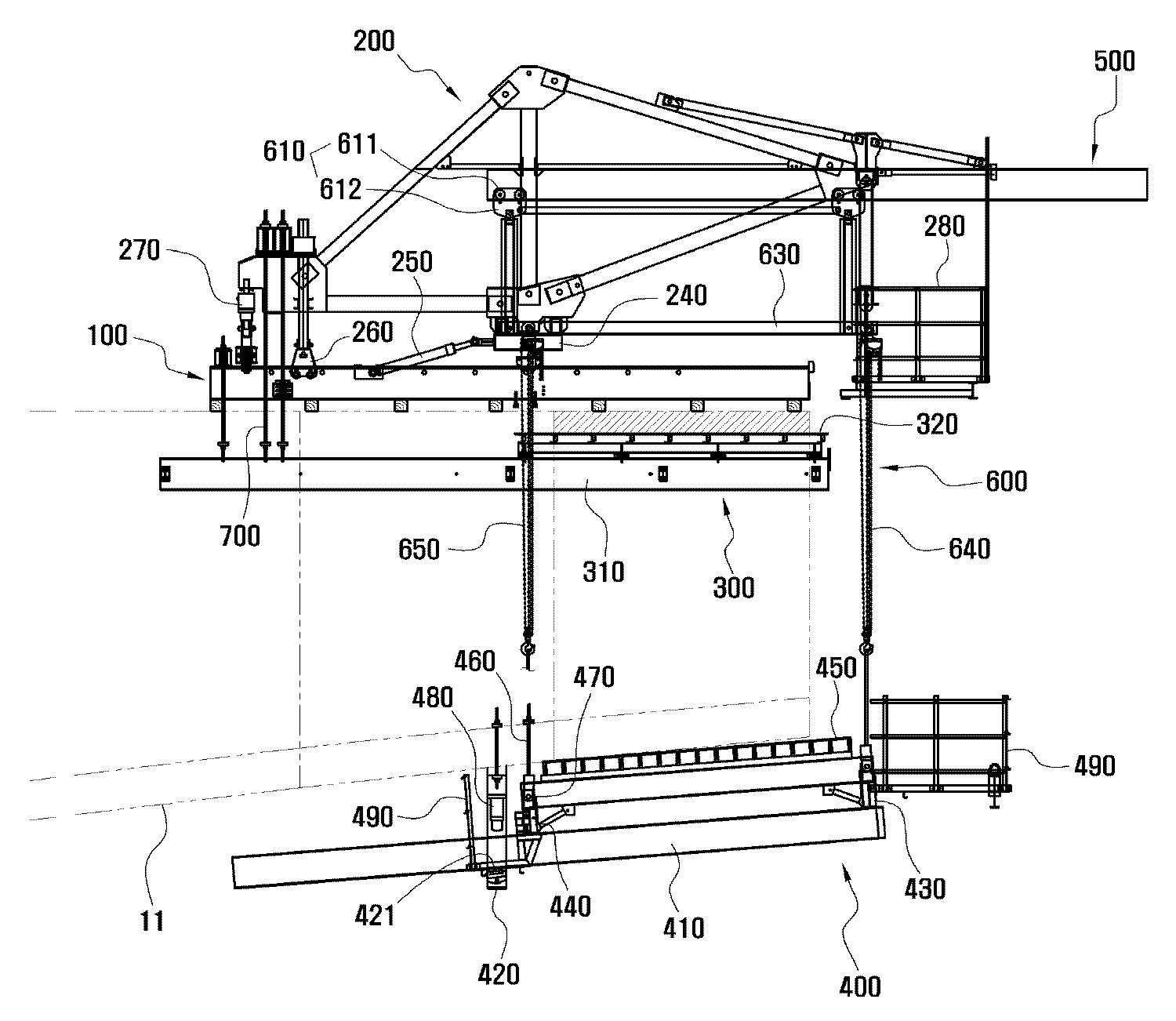
도 1은 본 발명의 실시예에 의한 폼 트래블러가 교량의 시공을 위해 설치된 상태를 도시한 측면 구성도.
도 2는 본 발명의 실시예에 의한 폼 트래블러의 측면 구성도.
도 3은 본 발명의 실시예에 의한 폼 트래블러의 정면 구성도.
도 4는 본 발명의 실시예에 의한 교량의 시공방법에 대한 흐름도.
도 5 내지 도 7은 본 발명의 실시예에 의한 교량의 시공방법을 단계적으로 도시한 공정도.1 is a side view showing a state in which a form traveler according to an embodiment of the present invention is installed for the construction of a bridge;
2 is a side view of a form traveler according to an embodiment of the present invention;
3 is a front view of a form traveler according to an embodiment of the present invention.
4 is a flowchart of a method of constructing a bridge according to an embodiment of the present invention.
5 to 7 are process drawings showing steps of a method of constructing a bridge according to an embodiment of the present invention.
이하 첨부된 도면을 참조하여 본 발명의 바람직한 실시예를 상세하게 설명한다.Hereinafter, preferred embodiments of the present invention will be described in detail with reference to the accompanying drawings.
'도 1' 내지 '도 3'에 도시된 바와 같이, 본 발명의 실시예에 의한 폼 트래블러는 FCM(Free Cantilever Method)공법을 이용한 교량(10)의 시공시 박스형의 거더(girder)(11)를 한 세그먼트(segment)씩 순차적으로 시공하기 위하여 사용되는 것으로서, 크게 메인레일(100), 프레임유닛(200), 내부거푸집유닛(300), 외부거푸집유닛(400), 서브레일(500) 및 중계유닛(600)으로 이루어진다.
As shown in FIGS. 1 to 3, the form traveler according to the embodiment of the present invention includes a
메인레일(100)은 교량(10)의 시공시 기 시공된 거더(11)의 선단(先端) 상면에 교량(10)의 시공방향을 따라 설치된다.The
메인레일(100)은 H형 빔(H-beam)으로 이루어지며, 거더(11)의 폭 방향을 따라 둘 이상이 상호 이격 배열된다.
The
프레임유닛(200)은 트러스(truss) 구조로 이루어져 메인레일(100)을 따라 이동 가능하게 설치되는 것으로서,The
각 메인레일(100)의 상부에 각각 설치된 메인프레임(210); 그리고A
각 메인프레임(210)의 전단부 및 후단부를 가로지르게 설치된 프런트프레임(220) 및 리어프레임(230);을 포함하여 이루어진다.
And a
메인프레임(210)은 마름모꼴의 트러스 구조로 이루어져 각 메인레일(100)의 상부에 기립 설치되며, 다른 구성요소들의 하중 및 새로이 시공될 거더 세그먼트의 하중을 지지하게 된다.
The
'도 2'에 도시된 바와 같이, 메인프레임(210)의 하부에는 프레임유닛(200)의 이동 및 고정을 위한 프런트보기(front bogie)(240), 런칭실린더(launching cylinder)(250), 리어보기(rear bogie)(260) 및 풀다운실린더(pull down cylinder)(270) 등이 설치되고, 프런트프레임(220)에는 상부작업대(280)가 아래로 늘어뜨려지게 설치된다.As shown in FIG. 2, a
이러한 장치들은 폼 트래블러에 적용되는 일반적인 구성품인바 상세한 설명은 생략한다.
These devices are general components that are applied to the form traveler, so detailed description is omitted.
내부거푸집유닛(300)은 거더(11)의 내측에 배치되도록 프레임유닛(200)에 연결되는 것으로서,The
거더(11)의 내측에 교량(10)의 시공방향을 따라 배치되되, 거더(11)의 폭을 따라 상호 이격 배열되는 둘 이상의 내부런칭빔(310); 그리고Two or more
내부런칭빔(310)의 상면 전부(前部)에 설치된 내부거푸집널(320);을 포함하여 이루어진다.
And an
내부런칭빔(310)은 그 전단부 및 후단부가 강봉(steel bar)(700)에 의해 각각 프런트프레임(220) 및 리어프레임(230)에 연결되고, 이에 따라 프레임유닛(200)의 런칭시 함께 이동된다.The
내부거푸집널(320)은 거더(11)의 내부와 상응하는 형상으로 이루어져 프레임유닛(200)의 런칭시 기 시공된 거더(11)의 전방으로 돌출되며, 이에 따라 거더(11)의 제작을 위해 타설된 콘크리트와 접하여 거더(11)의 내부 공간을 형성시키게 된다.
The
외부거푸집유닛(400)은 거더(11)의 하측에 배치되는 것으로서,The
거더(11)의 하측에 교량(10)의 시공방향을 따라 배치되되, 거더(11)의 폭을 따라 상호 이격 배열되는 둘 이상의 외부런칭빔(410);At least two
거더(11)의 하면에 고정되고, 각 외부런칭빔(410)의 후부(後部)를 진퇴동작 가능하게 지지하는 지지프레임(420);A
각 외부런칭빔(410)을 가로지르게 배치되되, 각 외부런칭빔(410)이 상면 전부(前部)에 상호 이격 배치되는 전방가로빔(430) 및 후방가로빔(440); 그리고A front
전방가로빔(430) 및 후방가로빔(440)의 상부에 설치된 외부거푸집널(450);을 포함하여 이루어진다.
And an
지지프레임(420)은 외부런칭빔(410)의 둘레를 감싸도록 형성되며, 앵커(anchor) 등의 고정수단에 의해 거더(11)의 하면에 고정된다.The
'도 2'에 도시된 바와 같이, 지지프레임(420)의 하단부에는 외부거푸집유닛(400)이 용이하게 런칭될 수 있도록 외부런칭빔(410)을 받치는 지지롤러(421)가 설치된다.
As shown in FIG. 2, a
전방가로빔(430) 및 후방가로빔(440)은 각각 외부런칭빔(410)의 상면 전단부 및 중앙부에 놓이게 되며, 전방가로빔(430)의 전방과 후방가로빔(440)의 후방에는 각각 하부작업대(490)가 설치된다.
The front
외부거푸집널(450)은 거더(11)의 외부와 상응하는 형상으로 이루어져 외부거푸집유닛(400)의 런칭시 기 시공된 거더(11)의 전방으로 돌출되며, 이에 따라 거더(11)의 제작을 위해 타설된 콘크리트와 접하여 거더(11)의 외형을 형성시키게 된다.
The
한편, 통상 교량(10)의 거더(11) 하부는 아치(arch)형으로 이루어지게 되는데, 이에 따라 본 발명의 외부거푸집유닛(400)은 각 외부런칭빔(410)의 기울기 조절을 위하여,The lower portion of the
'도 2'에 도시된 바와 같이,As shown in FIG. 2,
거더(11)의 하부에 하방 돌출되도록 설치된 앵커(460);An
앵커(460)와 후방가로빔(440)을 상호 회전 가능하게 연결하는 힌지연결부(470); 그리고A
각 지지프레임(420)에 설치되어, 각 외부런칭빔(410)의 후단부를 하방 가압하게 되는 구동잭(480);을 포함하여 이루어진 틸팅수단이 구비된다.
And a driving
앵커(460)는 거더(11)의 하부를 관통하도록 설치된 강봉으로 이루어지며, 힌지연결부(470)에 의해 후방가로빔(440)에 연결되어 후방가로빔(440)을 지지하게 된다.
The
구동잭(480)은 공지의 유압 잭(hydraulic jack)으로 이루어져 외부런칭빔(410)의 후단부를 가압하게 된다.
The driving
결국, 구동잭(480)이 하방 전진하여 외부런칭빔(410)의 후단부를 가압하면 외부거푸집널(450)이 힌지연결부(470)를 중심으로 상방 회전하게 되고, 구동잭(480)이 상방 후퇴하면 외부거푸집널(450)이 그 자중(自重)에 의해 힌지연결부(470)를 중심으로 하방 회전하게 되는데, 이에 따라 구동잭(480)의 스트로크(stroke)를 조절함으로써 외부런칭빔(410) 및 외부거푸집널(450)의 기울기를 조절할 수 있다.
As a result, when the driving
서브레일(500)은 교량(10)의 시공방향을 따라 배치되도록 프레임유닛(200)에 결합된다.The
서브레일(500)은 메인레일(100)과 마찬가지로 H형 빔으로 이루어지며, 프런트프레임(220) 및 리어프레임(230)의 양단부를 각각 연결하는 형태로 설치된다.
Like the
중계유닛(600)은 서브레일(500)과 외부거푸집유닛(400)을 연결하고, 서브레일(500)을 따라 이동 가능하게 설치되는 것으로서,The
서브레일(500)을 따라 이동되는 이송롤러(611) 및 이송롤러(611)와 연결된 브래킷(612)으로 이루어지고, 서브레일(500)을 따라 상호 이격 배열된 둘 이상의 트롤리(trolley)(610);A
트롤리(610)에 연결된 구동부(620);A driving
각 트롤리(610)를 연결하는 고정프레임(630); 그리고A fixed
외부거푸집유닛(400)의 전방가로빔(430) 및 후방가로빔(440)을 고정프레임(630)의 전단부 및 후단부에 각각 연결하는 전방체인블럭(640) 및 후방체인블럭(650);을 포함하여 이루어진다.
A
트롤리(610)는 각 서브레일(500)마다 둘 이상이 구비되어 상호 이격 배치된다.
At least two
구동부(620)는 트롤리(610)에 연결되어 트롤리(610)를 이동시키게 된다.The driving
구동부(620)는 '도 3'에 도시된 바와 같이 트롤리(610)에 직접 연결된 모터로 이루어질 수 있으며, 필요에 따라 각 트롤리(610)를 연결하는 체인을 포함하여 이루어져 체인을 수동식(手動式) 또는 전동식(電動式)으로 움직이게 하는 구조 등 작업자가 트롤리(610)를 수동식 또는 전동식으로 이동시킬 수 있는 범위 내에서 다양한 구조로 이루어질 수 있을 것이다.
The driving
고정프레임(630)은 각 트롤리(610)를 연결함으로써 각 트롤리(610)가 일정 간격을 유지할 수 있게 한다.The fixed
도시된 바에 의하면 고정프레임(630)은 사각 틀 형태로 이루어져 그 상단부가 각 트롤리(610)를 연결하도록 설치된다. 이와 같은 구조에 의하여 고정프레임(630)은 그 하단부에 전방체인블럭(640) 및 후방체인블럭(650)이 설치되는 자리를 제공하게 된다. 또한, 필요에 따라 고정프레임(630)의 하단부에 외부거푸집유닛(400)의 고정을 위한 강봉 등을 설치하거나, 별도의 작업대를 설치하여 사용할 수 있다.
As shown, the
전방체인블럭(640)은 두 개가 구비되어 고정프레임(630)의 전단부와 전방가로빔(430)의 양단부를 각각 연결하게 되고, 후방체인블럭(650)은 두 개가 구비되어 고정프레임(630)의 후단부와 후방가로빔(440)의 양단부를 각각 연결하게 된다.Two front chain blocks 640 are connected to the front end of the fixed
전방체인블럭(640) 및 후방체인블럭(650)은 스프로킷 및 이 스프로킷에 걸리어 늘어뜨려진 체인을 포함하는 공지의 체인블럭(chain block)으로 이루어지며, 이에 따라 작업자는 전방체인블럭(640) 및 후방체인블럭(650)을 이용하여 외부거푸집유닛(400)을 용이하게 인양할 수 있다.
The
결국, 중계유닛(600)은 외부거푸집유닛(400)을 지지한 상태에서 서브레일(500)을 따라 이동하게 됨으로써 외부거푸집유닛(400)이 내부거푸집유닛(300)과 상호 개별적으로 런칭될 수 있게 한다.
As a result, the
이하, '도 4' 내지 '도 7'을 참조하여 상기와 같은 구조로 이루어진 폼 트래블러를 이용한 본 발명의 교량 시공방법을 설명한다.
Hereinafter, a method of constructing a bridge according to the present invention using a foam traveler having the above structure will be described with reference to FIGS. 4 to 7. FIG.
'도 4' 내지 '도 7'에 도시된 바와 같이, 본 발명의 실시예에 의한 교량의 시공방법은 크게 외부거푸집유닛 런칭단계(S10), 외부거푸집유닛 틸팅단계(S20), 철근구조물 배치단계(S30), 내부거푸집유닛 런칭단계(S40) 및 콘크리트 타설단계(S50)를 포함하여 이루어진다.
As shown in FIGS. 4 'to 7', a method of constructing a bridge according to an embodiment of the present invention is roughly divided into an outer mold unit launch step S10, an outer mold unit tilting step S20, (S30), an inner mold unit launching step (S40), and a concrete pouring step (S50).
외부거푸집유닛 런칭단계(S10)는 '도 5'에 도시된 바와 같이, 기 시공된 거더(11)의 전방으로 외부거푸집유닛(400)을 런칭하는 단계이다.The outer die unit launching step S10 is a step of launching the
이 단계에서는 외부거푸집유닛(400)과 거더(11) 또는 프레임유닛(200)에 연결된 강봉이나 앵커 등을 분리한 후 중계유닛(600)의 구동부(620)를 작동시켜 서브레일(500)을 따라 트롤리(610)를 이동시킴으로써 외부거푸집유닛(400)을 기 시공된 거더(11)의 전방으로 런칭하게 된다.
In this step, after separating the steel rods or anchors connected to the
외부거푸집유닛 틸팅단계(S20)는 거더(11)의 하부 형상에 상응하도록 외부거푸집유닛(400)의 기울기를 조절하는 단계이다.The outer mold unit tilting step S20 is a step of adjusting the inclination of the
이 단계에서는 상술한 바와 같이 구동잭(480)의 스트로크를 조절함으로써 외부거푸집유닛(400)의 기울기를 조절하게 된다.In this step, the slope of the
이 단계는 런칭된 외부거푸집유닛(400)의 기울기와 새로이 시공될 거더 세그먼트의 형상을 감안하여 선택적으로 실시된다.
This step is selectively performed in consideration of the slope of the launched
철근구조물 배치단계(S30)는 '도 6'에 도시된 바와 같이, 외부거푸집유닛(400)의 내측에 기 조립된 철근구조물(20)을 배치하는 단계이다.The reinforcing steel structure arranging step S30 is a step of disposing the pre-assembled reinforcing
이 단계에서는 교량시공현장의 주변 또는 임의의 장소에서 거더(11)의 형상에 상응하도록 미리 제작해둔 철근구조물(20)을 크레인(crane) 등을 이용하여 외부거푸집널(450)의 내측에 배치하게 된다.
In this step, the reinforcing
내부거푸집유닛 런칭단계(S40)는 '도 7'에 도시된 바와 같이, 기 시공된 거더(11)의 전방으로 내부거푸집유닛(300)을 런칭하는 단계이다.The inner die unit launching step S40 is a step of launching the
이 단계에서는 런칭실린더(250)를 이용하여 프레임유닛(200)을 이동시킴으로써 내부거푸집유닛(300)을 기 시공된 거더(11)의 전방으로 런칭하게 된다.
In this step, the
한편, 내부거푸집유닛(300)의 런칭이 완료되면, 내부거푸집유닛(300) 및 외부거푸집유닛(400)을 고정하기 위하여 강봉(700)을 연결하는 공정과, 거더(11)의 상부 슬래브(slab)의 보강을 위한 철근을 배치하는 공정 등이 실시될 수 있다.
A step of connecting the
콘크리트 타설단계(S50)는 내부거푸집유닛(300) 및 외부거푸집유닛(400)에 콘크리트를 타설하는 단계이다.The concrete pouring step S50 is a step of pouring concrete into the
이 단계에서는 기 시공된 거더(11)의 전방으로 런칭된 내부거푸집유닛(300) 및 외부거푸집유닛(400)에 콘크리트를 타설 및 양생함으로써 기 시공된 거더(11)의 전방으로 새로운 거더 세그먼트를 연장 형성시키게 된다.
In this step, by placing and curing concrete in the
결국, 상기와 같은 구조 및 단계로 이루어진 본 발명의 폼 트래블러 및 이를 이용한 교량의 시공방법에 의하면, 내부거푸집유닛(300) 및 외부거푸집유닛(400)이 각각 메인레일(100) 및 서브레일(500)을 따라 상호 개별적으로 런칭됨으로써 교량(10) 시공시 외부거푸집유닛(400)만을 런칭한 상태에서 기 조립된 철근구조물(20)을 용이하게 배치할 수 있으며, 이에 따라 철근을 배치하는 과정이 신속하게 진행될 수 있으므로 공기(工期)를 대폭 단축할 수 있다.
The
이상에서 본 발명을 설명함에 있어 첨부된 도면을 참조하여 특정 형상과 구조를 갖는 "폼 트래블러 및 이를 이용한 교량의 시공방법"을 위주로 설명하였으나 본 발명은 당업자에 의하여 다양한 변형 및 변경이 가능하고, 이러한 변형 및 변경은 본 발명의 보호범위에 속하는 것으로 해석되어야 한다.
While the present invention has been described with reference to the accompanying drawings, a form traveler and a method of constructing a bridge using the form traveler have been described. However, the present invention can be variously modified and changed by those skilled in the art, Modifications and variations are to be construed as falling within the scope of protection of the present invention.
100 ; 메인레일
200 ; 프레임유닛
210 ; 메인프레임 220 ; 프런트프레임
230 ; 리어프레임 240 ; 프런트보기
250 ; 런칭실린더 260 ; 리어보기
270 ; 풀다운실린더 280 ; 상부작업대
300 ; 내부거푸집유닛
310 ; 내부런칭빔 320 ; 내부거푸집널
400 ; 외부거푸집유닛
410 ; 외부런칭빔 420 ; 지지프레임
430 ; 전방가로빔 440 ; 후방가로빔
450 ; 외부거푸집널 460 ; 앵커
470 ; 힌지연결부 480 ; 구동잭
490 ; 하부작업대
500 ; 서브레일
600 ; 중계유닛
610 ; 트롤리 620 ; 구동부
630 ; 고정프레임 640 ; 전방체인블럭
650 ; 후방체인블럭
700 ; 강봉100; Main rail
200; Frame unit
210;
230;
250; Launching
270; Pull-
300; Inside die unit
310; An
400; Outer die unit
410; An
430; A front
450; Outer die
470;
490; Lower workbench
500; Sub rail
600; Relay unit
610;
630; A fixed
650; Rear chain block
700; Bar
Claims (5)
트러스 구조로 이루어지고, 상기 메인레일(100)을 따라 이동 가능하게 설치된 프레임유닛(200);
거더(11)의 내측에 배치되도록 상기 프레임유닛(200)에 연결되고, 상기 프레임유닛(200)과 함께 이동되는 내부거푸집유닛(300);
거더(11)의 하측에 배치되는 외부거푸집유닛(400);
상기 프레임유닛(200)에 결합된 서브레일(500); 및
상기 서브레일(500)과 상기 외부거푸집유닛(400)을 연결하고, 상기 서브레일(500)을 따라 이동 가능하게 설치되는 중계유닛(600);을 포함하되,
상기 외부거푸집유닛(400)은
거더(11)의 하측에 교량(10)의 시공방향을 따라 배치되되, 거더(11)의 폭을 따라 상호 이격 배열되는 둘 이상의 외부런칭빔(410);
거더(11)의 하면에 고정되고, 상기 각 외부런칭빔(410)의 후부(後部)를 진퇴동작 가능하게 지지하는 지지프레임(420);
상기 각 지지프레임(420)의 하단부에 각각 설치되고, 상기 각 외부런칭빔(410)을 진퇴동작 가능하게 받치는 지지롤러(421);
상기 각 외부런칭빔(410)을 가로지르게 배치되되, 각 외부런칭빔(410)의 상면 전부(前部)에 상호 이격 배치되는 전방가로빔(430) 및 후방가로빔(440); 그리고
상기 전방가로빔(430) 및 후방가로빔(440)의 상부에 설치된 외부거푸집널(450);을 포함하여 이루어진 것을 특징으로 하는 폼 트래블러.
A main rail 100 installed on the upper surface of the box girder 11 along the installation direction of the bridge 10 when the bridge 10 is installed;
A frame unit (200) having a truss structure and movably installed along the main rail (100);
An inner mold unit 300 connected to the frame unit 200 to be disposed inside the girder 11 and moved together with the frame unit 200;
An outer mold unit 400 disposed under the girder 11;
A sub rail 500 coupled to the frame unit 200; And
And a relay unit 600 connecting the sub rail 500 and the outer die unit 400 and being installed to be movable along the sub rail 500,
The outer die unit 400
At least two external launching beams 410 arranged along the installation direction of the bridge 10 below the girders 11 and spaced apart from each other along the width of the girder 11;
A support frame 420 fixed to the lower surface of the girder 11 and supporting the rear portion of each of the outer launching beams 410 so as to be movable forward and backward;
A support roller 421 installed at a lower end of each of the support frames 420 to support the outer launch beams 410 so as to be movable forward and backward;
A front transverse beam 430 and a rear transverse beam 440 disposed transversely to the respective external launching beams 410 and spaced apart from each other on the top surface of each of the external launching beams 410; And
And an outer worktable (450) installed on the upper portion of the front transverse beam (430) and the rear transverse beam (440).
상기 외부거푸집유닛(400)은 상기 각 외부런칭빔(410)의 기울기 조절을 위한 틸팅수단을 더 포함하여 이루어지되,
상기 틸팅수단은
거더(11)의 하부에 하방 돌출되도록 설치된 앵커(460);
상기 앵커(460)와 상기 후방가로빔(440)을 회전 가능하게 연결하는 힌지연결부(470); 및
상기 각 지지프레임(420)에 설치되고, 상기 각 외부런칭빔(410)의 후단부를 하방 가압하게 되는 구동잭(480);을 포함하여 이루어진 것을 특징으로 하는 폼 트래블러.
The method according to claim 1,
The outer mold unit 400 further includes tilting means for adjusting the tilt of each of the outer launch beams 410,
The tilting means
An anchor 460 installed to protrude downward from a lower portion of the girder 11;
A hinge connection part 470 rotatably connecting the anchor 460 and the rear transverse beam 440; And
And a driving jack (480) installed on each of the support frames (420) and pressing the rear end of each of the outer launching beams (410) downward.
상기 중계유닛(600)은
상기 서브레일(500)을 따라 이동되는 이송롤러(611) 및 상기 이송롤러(611)와 연결된 브래킷(612)으로 이루어지고, 상기 서브레일(500)을 따라 상호 이격 배열된 둘 이상의 트롤리(610);
상기 트롤리(610)에 연결된 구동부(620);
상기 각 트롤리(610)를 연결하는 고정프레임(630); 그리고
상기 전방가로빔(430) 및 상기 후방가로빔(440)을 상기 고정프레임(630)의 전단부 및 후단부에 각각 연결하는 전방체인블럭(640) 및 후방체인블럭(650);을 포함하여 이루어진 것을 특징으로 하는 폼 트래블러.
3. The method according to claim 1 or 2,
The relay unit 600
Two or more trolleys 610 each composed of a conveying roller 611 moved along the sub rail 500 and a bracket 612 connected to the conveying roller 611 and spaced apart from each other along the sub rail 500, ;
A driving unit 620 connected to the trolley 610;
A fixed frame 630 connecting the trolleys 610; And
A front chain block 640 and a rear chain block 650 connecting the front transverse beam 430 and the rear transverse beam 440 to the front end and the rear end of the fixed frame 630, Wherein the form traveler is a form traveler.
기 시공된 거더(11)의 전방으로 상기 외부거푸집유닛(400)을 런칭하는 단계(S10);
상기 외부거푸집유닛(400)의 내측에 기 조립된 철근구조물(20)을 배치하는 단계(S30);
상기 내부거푸집유닛(300)을 런칭하는 단계(S40); 및
상기 내부거푸집유닛(300) 및 외부거푸집유닛(400)에 콘크리트를 타설하는 단계(S50);를 포함하여 이루어진 것을 특징으로 하는 교량의 시공방법.
A method of constructing a bridge using the form traveler of claim 1,
(S10) launching the outer formwork unit (400) in front of the previously installed girder (11);
Arranging a reinforced concrete structure 20 pre-assembled inside the outer formwork unit 400 (S30);
A step (S40) of launching the inner die unit 300; And
(S50) of pouring concrete into the inner mold unit (300) and the outer mold unit (400).
Priority Applications (1)
| Application Number | Priority Date | Filing Date | Title |
|---|---|---|---|
| KR1020140061781A KR101657994B1 (en) | 2014-05-22 | 2014-05-22 | Form traveler, and bridge construction method for using the same |
Applications Claiming Priority (1)
| Application Number | Priority Date | Filing Date | Title |
|---|---|---|---|
| KR1020140061781A KR101657994B1 (en) | 2014-05-22 | 2014-05-22 | Form traveler, and bridge construction method for using the same |
Publications (2)
| Publication Number | Publication Date |
|---|---|
| KR20150134694A KR20150134694A (en) | 2015-12-02 |
| KR101657994B1 true KR101657994B1 (en) | 2016-09-20 |
Family
ID=54883097
Family Applications (1)
| Application Number | Title | Priority Date | Filing Date |
|---|---|---|---|
| KR1020140061781A KR101657994B1 (en) | 2014-05-22 | 2014-05-22 | Form traveler, and bridge construction method for using the same |
Country Status (1)
| Country | Link |
|---|---|
| KR (1) | KR101657994B1 (en) |
Cited By (1)
| Publication number | Priority date | Publication date | Assignee | Title |
|---|---|---|---|---|
| KR102491148B1 (en) * | 2021-07-28 | 2023-01-19 | 현대건설(주) | Form traveller, construction method for girder segment of fcm bridgeand construction method for fcm bridge using the same |
Families Citing this family (12)
| Publication number | Priority date | Publication date | Assignee | Title |
|---|---|---|---|---|
| CN107201727A (en) * | 2017-07-25 | 2017-09-26 | 利越集团有限公司 | Cross a river Continuous box girder with cast-in-place cantilever method construction environmental-protection engineering method |
| CN107893376B (en) * | 2017-11-16 | 2023-12-12 | 中铁七局集团广州工程有限公司 | Method and device for erecting container type railway overhead longitudinal beam |
| CN107974942B (en) * | 2017-11-30 | 2019-03-15 | 中铁二十局集团有限公司 | A kind of abrupt slope side rigid frame-continuous girder end bay construction method |
| CN108086169B (en) * | 2017-12-13 | 2019-08-09 | 中国铁建大桥工程局集团有限公司 | The installation method for improving of bridge construction mobile formwork |
| CN108824195B (en) * | 2018-06-13 | 2019-12-31 | 贵州路桥集团有限公司 | Ultra-light hanging basket main truss |
| WO2020221944A1 (en) * | 2019-04-29 | 2020-11-05 | Gestion Y Actividades Secozam, Sl | Tool for dismounting travellers for concreting large arches of viaducts |
| CN110374007A (en) * | 2019-07-22 | 2019-10-25 | 中铁大桥局集团有限公司 | A kind of mobile formwork and its construction method reducing die sinking distance |
| CN110629676A (en) * | 2019-08-20 | 2019-12-31 | 中铁九桥工程有限公司 | Frame structure of large-tonnage beam erecting crane |
| CN112853986B (en) * | 2021-01-13 | 2022-04-12 | 中铁大桥局集团有限公司 | Movable formwork for construction of fabricated truss girder |
| CN113846575B (en) * | 2021-11-16 | 2023-03-21 | 中国建筑第四工程局有限公司 | Automatic operation method for internal mold of cradle cantilever construction |
| CN115262423A (en) * | 2022-08-03 | 2022-11-01 | 中国十九冶集团有限公司 | Bridge hanging basket construction method |
| CN115162195B (en) * | 2022-08-04 | 2023-04-28 | 中铁一局集团(广州)建设工程有限公司 | Internal mold hanging bracket device for construction of prestressed concrete short-tower cable-stayed bridge |
Citations (2)
| Publication number | Priority date | Publication date | Assignee | Title |
|---|---|---|---|---|
| KR200352053Y1 (en) | 2004-03-15 | 2004-06-04 | 엠에스아시아 주식회사 | A form traveller |
| KR101259031B1 (en) | 2012-10-16 | 2013-04-29 | 컨텍이앤씨 주식회사 | Form traveller having transversal frame, and launching method for the same |
Family Cites Families (2)
| Publication number | Priority date | Publication date | Assignee | Title |
|---|---|---|---|---|
| JP3946342B2 (en) * | 1998-03-09 | 2007-07-18 | 三井住友建設株式会社 | Bridge erection device |
| KR101373098B1 (en) * | 2011-08-02 | 2014-03-12 | (유)하남종합건설 | Construction appratus for composit truss free cantilever bridge and construction method of composit truss free cantilever bridge using the same |
-
2014
- 2014-05-22 KR KR1020140061781A patent/KR101657994B1/en active IP Right Grant
Patent Citations (2)
| Publication number | Priority date | Publication date | Assignee | Title |
|---|---|---|---|---|
| KR200352053Y1 (en) | 2004-03-15 | 2004-06-04 | 엠에스아시아 주식회사 | A form traveller |
| KR101259031B1 (en) | 2012-10-16 | 2013-04-29 | 컨텍이앤씨 주식회사 | Form traveller having transversal frame, and launching method for the same |
Cited By (1)
| Publication number | Priority date | Publication date | Assignee | Title |
|---|---|---|---|---|
| KR102491148B1 (en) * | 2021-07-28 | 2023-01-19 | 현대건설(주) | Form traveller, construction method for girder segment of fcm bridgeand construction method for fcm bridge using the same |
Also Published As
| Publication number | Publication date |
|---|---|
| KR20150134694A (en) | 2015-12-02 |
Similar Documents
| Publication | Publication Date | Title |
|---|---|---|
| KR101657994B1 (en) | Form traveler, and bridge construction method for using the same | |
| CN102199916B (en) | Cradle for pouring bridge cantilever and construction method of cradle | |
| US20150211242A1 (en) | Panel support bracket | |
| KR101654742B1 (en) | Movable scaffolding system mounted upper-structure of bridge and bridge construction method therewith | |
| US10981295B2 (en) | Upright concrete wall panel form apparatus and associated methods | |
| JP4403051B2 (en) | Corrugated steel web bridge construction method | |
| KR20210054303A (en) | Concrete lining formwork for tunnels with sloped construction | |
| JP6752160B2 (en) | Mobile work vehicle | |
| JP2008274637A (en) | Construction method for continuous viaduct | |
| KR101623047B1 (en) | Bridge segment launching method using side pulling apparatus | |
| CN108824199B (en) | Arch bridge construction method of underneath type hanging basket | |
| JP2011157720A (en) | Method for constructing railway reinforced concrete rigid-frame structure viaduct | |
| JP6966853B2 (en) | How to place concrete on an inclined surface and mobile formwork equipment | |
| JP2007092313A (en) | Construction method for precast concrete corrugated steel plate web box girder | |
| JP2020183678A (en) | Box girder construction method and construction system | |
| CN114214915A (en) | Partially prefabricated and assembled corrugated steel web combined box girder bridge structure and construction method | |
| JP4329535B2 (en) | Mobile work vehicle for overhanging slabs | |
| KR101082418B1 (en) | mold apparatus for forming concrete slab of bridge | |
| KR101730798B1 (en) | Form traveller | |
| KR101200246B1 (en) | Toggle link means steel-fram assembly jig system | |
| JP3032477B2 (en) | Moving scaffold for floor slab assembly | |
| JP6449637B2 (en) | Building construction method | |
| KR101078564B1 (en) | moving device of side scaffolding system | |
| JP2000087315A (en) | Method and device for construction of floor slab | |
| KR20180049533A (en) | Manufacturing method of precast P.S composite girder using support devices with ability of height adjustment |
Legal Events
| Date | Code | Title | Description |
|---|---|---|---|
| A201 | Request for examination | ||
| E902 | Notification of reason for refusal | ||
| E701 | Decision to grant or registration of patent right | ||
| GRNT | Written decision to grant | ||
| FPAY | Annual fee payment |
Payment date: 20190910 Year of fee payment: 4 |