KR101260292B1 - Grouting device and tunnel reinforce method - Google Patents
Grouting device and tunnel reinforce method Download PDFInfo
- Publication number
- KR101260292B1 KR101260292B1 KR1020120094339A KR20120094339A KR101260292B1 KR 101260292 B1 KR101260292 B1 KR 101260292B1 KR 1020120094339 A KR1020120094339 A KR 1020120094339A KR 20120094339 A KR20120094339 A KR 20120094339A KR 101260292 B1 KR101260292 B1 KR 101260292B1
- Authority
- KR
- South Korea
- Prior art keywords
- tunnel
- hole
- grouting device
- insertion hole
- delete delete
- Prior art date
Links
Images


Classifications
-
- E—FIXED CONSTRUCTIONS
- E21—EARTH DRILLING; MINING
- E21D—SHAFTS; TUNNELS; GALLERIES; LARGE UNDERGROUND CHAMBERS
- E21D9/00—Tunnels or galleries, with or without linings; Methods or apparatus for making thereof; Layout of tunnels or galleries
- E21D9/001—Improving soil or rock, e.g. by freezing; Injections
-
- E—FIXED CONSTRUCTIONS
- E21—EARTH DRILLING; MINING
- E21D—SHAFTS; TUNNELS; GALLERIES; LARGE UNDERGROUND CHAMBERS
- E21D20/00—Setting anchoring-bolts
- E21D20/02—Setting anchoring-bolts with provisions for grouting
- E21D20/028—Devices or accesories for injecting a grouting liquid in a bore-hole
-
- E—FIXED CONSTRUCTIONS
- E21—EARTH DRILLING; MINING
- E21D—SHAFTS; TUNNELS; GALLERIES; LARGE UNDERGROUND CHAMBERS
- E21D21/00—Anchoring-bolts for roof, floor in galleries or longwall working, or shaft-lining protection
- E21D21/0026—Anchoring-bolts for roof, floor in galleries or longwall working, or shaft-lining protection characterised by constructional features of the bolts
-
- E—FIXED CONSTRUCTIONS
- E02—HYDRAULIC ENGINEERING; FOUNDATIONS; SOIL SHIFTING
- E02D—FOUNDATIONS; EXCAVATIONS; EMBANKMENTS; UNDERGROUND OR UNDERWATER STRUCTURES
- E02D3/00—Improving or preserving soil or rock, e.g. preserving permafrost soil
- E02D3/12—Consolidating by placing solidifying or pore-filling substances in the soil
Landscapes
- Engineering & Computer Science (AREA)
- Mining & Mineral Resources (AREA)
- Life Sciences & Earth Sciences (AREA)
- General Life Sciences & Earth Sciences (AREA)
- Geochemistry & Mineralogy (AREA)
- Geology (AREA)
- Structural Engineering (AREA)
- Soil Sciences (AREA)
- Environmental & Geological Engineering (AREA)
- Lining And Supports For Tunnels (AREA)
- Excavating Of Shafts Or Tunnels (AREA)
Abstract
Description
본 발명은 그라우팅장치를 이용한 터널 보강공법에 관한 것으로, 특히 터널을 천공하여 천공홀을 형성하고, 상기 천공홀에 충전식 록볼트를 삽입한 후, 주입관을 통해 모르타르를 충전한 후, 상기 충전식 록볼트의 선단 외주면에 지압판을 끼우고, 상기 지압판의 상단에 너트를 체결하는 그라우팅장치를 이용한 터널 보강공법에 관한 것이다.The present invention relates to a tunnel reinforcement method using a grouting device, and in particular, to form a drill hole by drilling a tunnel, inserting a rechargeable rock bolt into the drill hole, and then filling the mortar through an injection tube, and then charging the lock. It relates to a tunnel reinforcement method using a grouting device for inserting the pressure plate on the outer peripheral surface of the end of the bolt, and fastening the nut to the upper end of the pressure plate.
각종 토목 및 건축공사, 특히 터널공사에 있어서, 터널의 굴착 후 터널의 붕괴를 방지하기 위하여 록볼트가 많이 설치된다.In various civil and building works, especially in tunnel work, a lot of rock bolts are installed to prevent the collapse of the tunnel after the excavation of the tunnel.
록볼트는 벽면에 구멍을 뚫고 그 속에 볼트를 끼운 다음 지압판을 끼우고 너트를 단단히 죔으로써 굴착시 발파 등으로 인하여 연약해진 암반을 견고하고 안정된 암반에 고정시켜 암반의 보강 및 낙석을 방지하기 위하여 사용된다.Rockbolt is used to prevent rock reinforcement and rockfall by fixing rock to weak rock due to blasting during excavation by drilling a hole in the wall, inserting bolt in it, fastening nut and fastening nut. do.
록볼트에는 암반 등에 고정되는 형태에 따라 쐐기형 볼트, 신축형 볼트, 접착형 볼트로 구분될 수 있다.Rock bolts may be divided into wedge-type bolts, telescopic bolts, adhesive bolts according to the shape that is fixed to the rock.
쐐기형 볼트는 볼트 선단의 확대를 위하여 쐐기를 가볍게 끼워서 삽입하고 볼트의 다른 끝을 망치 등으로 가볍게 타격하여 선단부의 확대부를 확대시켜 정착한다.The wedge-shaped bolt is inserted by inserting the wedge lightly for the expansion of the tip of the bolt, and lightly hitting the other end of the bolt with a hammer or the like to enlarge and fix the enlarged portion of the tip.
신축형 볼트는 테이퍼(taper)가 붙은 셀(shell)과 콘(cone)을 붙여서 볼트를 회전시켜 셀을 확장시켜 이에 따른 마찰력을 이용한다.The telescopic bolt attaches a shell and a cone to which a taper is attached, and rotates the bolt to expand the cell to use the friction force accordingly.
상기한 접착형 볼트의 시공은 천공 드릴을 이용하여 암반에 소정의 간격으로 구멍을 뚫어 록볼트를 삽입하고 모르타르 충전기를 이용하여 구멍에 모르타르를 주입한 후 지압판 및 너트를 사용하여 암반에 고정한다. In the construction of the adhesive bolt, a rock bolt is inserted into the rock at a predetermined interval using a drill, and mortar is injected into the hole using a mortar charger, and then fixed to the rock using a pressure plate and a nut.
이때 수평각 이상의 각도로 천공된 구멍의 모르타르 주입과정에서 구멍 내부로부터 모르타르의 흘러내림 현상이 발생하며, 밀폐장치의 밀폐력이 약하게 되면 모르타르의 충전밀도가 떨어져 최종 부착강도가 떨어진다. At this time, the mortar flows from the inside of the hole during the injection of the mortar of the hole drilled at an angle greater than the horizontal angle. If the sealing force of the sealing device is weak, the packing density of the mortar falls and the final adhesion strength is lowered.
또한, 천공 내부의 모르타르가 완전히 굳어 록볼트의 고정지지력을 발생할 때까지 록볼트가 떨어질 위험성이 있었다.In addition, there was a risk that the rock bolt would fall until the mortar in the perforation completely hardened to generate a fixed bearing force of the rock bolt.
이에, 본 발명은 상기한 바와 같은 제문제점을 해결하기 위해 안출된 것으로, 록볼트 및 모르타르의 충전밀도를 향상시키고, 부착강도를 증진시켜 터널 내부에 록볼트를 안정되게 시공할 수 있도록 한 그라우팅장치를 이용한 터널 보강공법을 제공하는데 그 목적이 있다.Accordingly, the present invention has been made to solve the problems described above, the grouting device to improve the filling density of the rock bolt and mortar, and to increase the adhesion strength to stably install the rock bolt inside the tunnel The purpose is to provide a tunnel reinforcement method using.
상기한 목적을 달성하기 위한 본 발명에 따른 그라우팅장치를 이용한 터널 보강공법은 터널의 소정의 위치를 일정한 길이 및 직경으로 천공하여 천공홀을 형성하는 단계(Ⅰ); 상기 천공홀에 전체적으로 원기둥 형상으로 이루어지고, 상기 원기둥 형상의 가운데에 록볼트삽입공이 형성되고, 상기 록볼트삽입공의 일측과 타측에 각각 주입관 삽입공과, 공기배출관 삽입공이 형성된 슬리브와; 상기 슬리브의 록볼트삽입공에 삽입되는 록볼트와; 상기 슬리브의 주입관 삽입공에 삽입되는 주입관과; 상기 슬리브의 공기배출관 삽입공에 삽입되는 공기배출관과; 상기 슬리브에 밀접하게 배치되며, 상기 록볼트와 주입관 및 공기배출관을 감싸며, 실링재가 도포된 코킹재로 구성된 그라우팅장치를 삽입하는 단계(Ⅱ); 상기 그라우팅장치가 삽입된 천공홀에 주입관을 통해 모르타르 또는 시멘트밀크를 충전하는 단계(Ⅲ); 상기 그라우팅장치의 선단 외주면에 지압판을 끼우고, 상기 지압판의 상단에 너트를 체결하는 단계(Ⅳ)로 이루어짐을 특징으로 한다.Tunnel reinforcement method using the grouting apparatus according to the present invention for achieving the above object comprises the steps of (I) to form a hole by drilling a predetermined position of the tunnel to a predetermined length and diameter; A sleeve having an overall cylindrical shape in the drilling hole, and having a rock bolt insertion hole formed in the center of the cylinder shape, each having an injection tube insertion hole and an air discharge tube insertion hole at one side and the other side of the rock bolt insertion hole; A rock bolt inserted into the rock bolt insertion hole of the sleeve; An injection tube inserted into an injection tube insertion hole of the sleeve; An air discharge pipe inserted into the air discharge pipe insertion hole of the sleeve; Inserting a grouting device disposed closely to the sleeve, surrounding the rock bolt, the injection pipe, and the air discharge pipe, and comprising a caulking material coated with a sealing material (II); Filling the mortar or cement milk through an injection tube into the drilling hole into which the grouting device is inserted (III); Inserting the pressure plate on the outer peripheral surface of the front end of the grouting device, characterized in that the step (IV) of fastening the nut to the upper end of the pressure plate.
이상에서 설명한 바와 같이, 본 발명에 따른 그라우팅장치를 이용한 터널 보강공법은 다음과 같은 효과가 있다.As described above, the tunnel reinforcement method using the grouting device according to the present invention has the following effects.
첫째, 본 발명은 터널을 천공하여 천공홀을 형성하고, 상기 천공홀에 충전식 록볼트를 삽입한 후, 주입관을 통해 모르타르를 충전한 후, 상기 충전식 록볼트의 선단 외주면에 지압판을 끼우고, 상기 지압판의 상단에 너트를 체결함으로써, 터널의 지반 내부를 더욱 밀실하고, 충실하게 그라우팅하는 효과가 있다.First, the present invention is to form a punching hole by drilling a tunnel, and after inserting the charging rock bolt into the drilling hole, and after filling the mortar through the injection pipe, inserting the pressure plate on the outer peripheral surface of the front end of the charging rock bolt, By fastening the nut to the upper end of the pressure plate, there is an effect to more closely seal the ground inside the tunnel, and grouting faithfully.
둘째, 본 발명은 터널의 소정의 위치에 1차 시멘트밀크를 타설하고 상기 1차 시멘트밀크 주변에 격자지보를 설치한 후, 상기 1차 시멘트밀크와 격자지보 간에 일정한 직경 및 깊이로 상향으로 5∼10°로 천공하여 천공홀을 형성하고, 상기 휘폴링을 삽입한 후, 상기 그라우팅장치의 그라우팅호스를 통해 모르타르를 충전한 후, 천공홀 근처를 2차 시멘트밀크를 타설함으로써, 터널 내부를 용이하게 굴착할 수 있고, 지반 내부를 밀실하고 확실하게 차수 및 터널 지반 내부를 견고히 보강할 수 있다.Second, the present invention after placing the primary cement milk at a predetermined position of the tunnel and installing the grid support around the primary cement milk, 5 ~ upward in a constant diameter and depth between the primary cement milk and the grid support After drilling at 10 ° to form a hole, inserting the whippling, filling the mortar through the grouting hose of the grouting device, and then pouring a secondary cement milk near the hole to facilitate the inside of the tunnel. Excavation can be carried out, and the inside of the ground can be tightly closed and firmly reinforced in the order and tunnel ground.
셋째, 본 발명은 모르타르 또는 시멘트밀크가 천공홀과 강관의 주변을 충전함으로써, 지반 내부를 더욱 밀실하고, 충실하게 그라우팅하는 효과가 있다.Third, the present invention has the effect of mortar or cement milk to fill the periphery of the perforation hole and the steel pipe, further close the ground, and grout faithfully.
도 1은 본 발명에 따른 충전식 록볼트 그라우팅을 도시한 예시도,
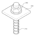
도 2는 본 발명에 따른 충전식 록볼트 그라우팅과 록볼트지압판과의 결합관계를 도시한 사시도,
도 3a 및 도 3b는 본 발명에 따른 충전식 록볼트 그라우팅의 슬리브를 도시한 평면도,
도 4는 본 발명에 따른 충전식 록볼트 그라우팅으로 터널을 보강한 상태를 도시한 상세도,
도 5a 내지 5d는 본 발명에 따른 충전식 록볼트 그라우팅으로 터널을 보강하는 상태를 도시한 공정도,
도 6은 본 발명에 따른 훠폴링을 도시한 예시도,
도 7은 본 발명에 따른 훠폴링으로 터널을 보강한 상태를 도시한 정면도,
도 8은 본 발명에 따른 훠폴링으로 터널을 보강하는 상태를 도시한 상세도,
도 9a 및 9b는 본 발명에 따른 훠폴링으로 터널을 시공하는 상태를 도시한 공정도.1 is an exemplary view showing a rechargeable rock bolt grouting according to the present invention,
Figure 2 is a perspective view showing a coupling relationship between the rock-bolt grouting and rock bolt pressure plate according to the present invention,
3a and 3b are a plan view showing a sleeve of a rechargeable rock bolt grouting according to the present invention;
Figure 4 is a detailed view showing a state of reinforcing the tunnel with a rock-bolt grouting charging according to the present invention,
5a to 5d is a process diagram showing a state of reinforcing a tunnel with a rock-bolt grouting charge according to the present invention,
6 is an exemplary view showing wet polling according to the present invention;
7 is a front view illustrating a state in which a tunnel is reinforced with wet-polling according to the present invention;
8 is a detailed view showing a state of reinforcing the tunnel with wet-polling according to the present invention;
Figure 9a and 9b is a process diagram showing a state in which the construction of the tunnel by wet polling in accordance with the present invention.
이하, 본 발명을 첨부한 예시도면을 참조하여 상세히 설명한다.Hereinafter, with reference to the accompanying drawings, the present invention will be described in detail.
[충전식 록볼트 그라우팅][Rechargeable Rock Bolt Grouting]
도 1은 본 발명에 따른 충전식 록볼트 그라우팅을 도시한 예시도이고, 도 2는 본 발명에 따른 충전식 록볼트 그라우팅의 슬리브를 도시한 평면도이며, 도 3은 본 발명에 따른 충전식 록볼트 그라우팅과 록볼트지압판과의 결합관계를 도시한 사시도이다.1 is an exemplary view showing a rechargeable rock bolt grouting according to the present invention, FIG. 2 is a plan view showing a sleeve of a rechargeable rock bolt grouting according to the present invention, and FIG. 3 is a rechargeable rock bolt grouting and lock according to the present invention. It is a perspective view which shows the coupling relationship with a bolt pressure plate.
이들 도면에 도시된 바와 같이, 본 발명에 따른 그라우팅장치(A)는 전체적으로 원기둥 형상으로 이루어지고, 상기 원기둥 형상의 가운데에 록볼트삽입공(202)이 형성되고, 상기 록볼트삽입공(202)의 일측과 타측에 각각 주입관 삽입공(204)과, 공기배출관 삽입공(206)이 형성된 슬리브(200)와; 상기 슬리브(200)의 록볼트삽입공(202)에 삽입되는 록볼트(210)와; 상기 슬리브(200)의 주입관 삽입공(204)에 삽입되는 주입관(220)과; 상기 슬리브(200)의 공기배출관 삽입공(204)에 삽입되는 공기배출관(230)과; 상기 슬리브(200)에 밀접하게 배치되며, 상기 록볼트(210)와 주입관(220) 및 공기배출관(230)을 감싸며 실링재가 도포된 코킹재(240)로 구성된다.As shown in these figures, the grouting device (A) according to the present invention is formed in a cylindrical shape as a whole, a rock
즉, 본 발명에 따른 그라우팅장치는 슬리브(200), 록볼트(210), 주입관(220) 및 공기배출관(230)이 유기적으로 결합된 장치이다.That is, the grouting device according to the present invention is a device in which the
여기서, 상기 슬리브(200)는 전체적으로 원기둥 형상으로 이루어지고, 상기 원기둥 형상의 가운데에 록볼트삽입공(202)이 형성되고, 상기 록볼트삽입공(202)의 일측과 타측에 각각 주입관 삽입공(204)과, 공기배출관 삽입공(206)이 형성된 구조이다.Here, the
이와 같은 슬리브(200)는 록볼트(210), 주입관(220), 공기배출관(230)의 고정과 실링재가 도포된 코킹재(240)의 밀림을 방지하는 기능을 한다.The
또한, 상기 록볼트삽입공(202)은 전체적으로 정원형상으로 이루어지되, 양측이 외측으로 돌출 연장되는 단면 형상으로 구성된다.In addition, the rock
그리고, 상기 록볼트(210)는 굴착단면의 크기 및 지반조건에 따라 길이를 선택적으로 사용하되, 설계에 맞춰 길이가 3m∼8m, 직경은 D16㎜∼D38㎜이며, 일반적으로 D25㎜를 사용한다.The length of the
또한, 상기 주입관(220)은 모르타르를 주입하는 관으로, 공기배출관(230)보다는 직경이 같거나, 큰 것을 사용하며, 상향 주입에서는 공기배출관(230)에 비하여 길이가 짧은 것을 사용하고, 하향 주입에서는 공기배출관(230)에 비하여 길이가 긴 것을 사용한다. In addition, the
그리고, 상기 공기배출관(230)은 공기를 배출하는 관으로, 상기 주입관(220)의 직경에 비해 같거나, 작은 것을 사용한다.In addition, the
여기서, 터널에 상향으로 설치시에는 길이가 긴 것을 사용하고, 하향으로 설치시에는 길이가 입구에서 약 50∼100㎜로 한다.Here, a long one is used to install the tunnel upwards, and a length of about 50 to 100 mm is set at the entrance when installed downward.
또한, 상기 코킹재(240)는 전체적으로 원기둥 형상으로 고무, 목재 또는 압축성이 있는 플라스틱재로 이루어져 록볼트(210)와 주입관(220) 및 공기배출관(230)을 감싸며, 실링재가 도포되며, 모르타르의 역류를 방지하는 기능을 한다. In addition, the
그리고, 상기 록볼트(210)에는 선단 외주면에 지압판(250)이 설치되고, 상기 지압판(250)의 상단에 너트(260)가 설치된다.In addition, the
이하, 상기한 바와 같은 구성으로 이루어진 본 발명에 따른 그라우팅장치를 이용한 터널 보강에 대해 설명한다.Hereinafter, a tunnel reinforcement using the grouting device according to the present invention having the configuration as described above will be described.
도 4는 본 발명에 따른 그라우팅장치로 터널을 보강한 상태를 도시한 상세도이고, 도 5a 내지 5d는 본 발명에 따른 그라우팅장치로 터널을 보강하는 상태를 도시한 공정도이다.4 is a detailed view illustrating a state in which a tunnel is reinforced with a grouting apparatus according to the present invention, and FIGS. 5A to 5D are process diagrams illustrating a state in which a tunnel is reinforced with a grouting apparatus according to the present invention.
이들 도면에 도시된 바와 같이, 본 발명에 따른 그라우팅장치를 이용한 터널 보강공법은 터널(T)의 소정의 위치를 일정한 길이 및 직경으로 천공하여 천공홀(H)을 형성하는 단계(Ⅰ); 상기 천공홀(H)에 전체적으로 원기둥 형상으로 이루어지고, 상기 원기둥 형상의 가운데에 록볼트삽입공(202)이 형성되고, 상기 록볼트삽입공(202)의 일측과 타측에 각각 주입관 삽입공(204)과, 공기배출관 삽입공(206)이 형성된 슬리브(200)와; 상기 슬리브(200)의 록볼트삽입공(202)에 삽입되는 록볼트(210)와; 상기 슬리브(200)의 주입관 삽입공(204)에 삽입되는 주입관(220)과; 상기 슬리브(200)의 공기배출관 삽입공(204)에 삽입되는 공기배출관(230)과; 상기 슬리브(200)에 밀접하게 배치되며, 상기 록볼트(210)와 주입관(220) 및 공기배출관(230)을 감싸며, 실링재가 도포된 코킹재(240)로 구성된 그라우팅장치(A)를 삽입하는 단계(Ⅱ); 상기 그라우팅장치(A)가 삽입된 천공홀(H)에 주입관(220)을 통해 모르타르 또는 시멘트밀크를 충전하는 단계(Ⅲ); 상기 그라우팅장치(A)의 선단 외주면에 지압판(250)을 끼우고, 상기 지압판(250)의 상단에 너트(260)를 체결하는 단계(Ⅳ)로 이루어진다.As shown in these figures, the tunnel reinforcement method using the grouting apparatus according to the present invention comprises the steps of (I) to form a punching hole (H) by drilling a predetermined position of the tunnel (T) to a predetermined length and diameter; The drilling hole (H) is formed in a cylindrical shape as a whole, the lock
즉, 본 발명에 따른 그라우팅장치를 이용한 터널 보강공법은 천공홀(H) 형성단계(Ⅰ), 그라우팅장치(A) 삽입단계(Ⅱ), 모르타르 또는 시멘트밀크 충전단계(Ⅲ), 그라우팅장치 체결단계(Ⅳ)를 순차적으로 시행하여 터널을 보강한다.That is, the tunnel reinforcement method using the grouting device according to the present invention is a hole (H) forming step (I), grouting device (A) insertion step (II), mortar or cement milk filling step (III), grouting device fastening step Strengthen the tunnel by performing (IV) sequentially.
여기서, 상기 천공홀(H) 형성단계(Ⅰ)는 천공 직경은 Φ38∼46㎜로 하고, 길이는 3.0m∼8.0m로 하여 터널 라이닝면에 수직방향으로 천공하여 천공홀(H)을 형성한다.Here, in the forming step (I) of the drilling hole (H), the drilling diameter is Φ38 to 46mm and the length is 3.0m to 8.0m, so that the drilling hole (H) is formed by drilling in the direction perpendicular to the tunnel lining surface. .
이어서, 상기 천공홀(H)에 그라우팅장치(A)를 삽입하기 전에 천공홀(H) 내부를 청소하고, 천공홀(H) 내부의 공기를 완전히 배출시킨다.Subsequently, before inserting the grouting device A into the drilling hole H, the inside of the drilling hole H is cleaned, and the air inside the drilling hole H is completely discharged.
이어서, 그라우팅장치(A) 삽입단계(Ⅱ)는 천공홀(H)에 그라우팅장치(A)를 삽입하는 단계이다.Subsequently, the grouting device A insertion step (II) is a step of inserting the grouting device (A) into the drilling hole (H).
이어서, 모르타르 또는 시멘트밀크 충전단계(Ⅲ)는 상기 그라우팅장치(A)가 삽입된 천공홀(H)의 입구를 코킹재로 막은 후, 주입관(220)을 통해 모르타르 또는 시멘트밀크를 정압, 정량 주입한다.Subsequently, in the filling of mortar or cement milk (III), the caulking material is blocked by the inlet of the hole H into which the grouting device A is inserted, and then the mortar or cement milk is positively and quantitated through the
이때, 천공홀(H) 내부의 공기를 완전히 배출시킨다.At this time, the air inside the drilling hole (H) is completely discharged.
여기서, 상기 모르타르는 시멘트, WGS300, WGSC1, 물을 적절한 비율에 맞춰 사용한다.Here, the mortar is used in cement, WGS300, WGSC1, water in an appropriate ratio.
구분
division
시멘트(㎏)
Cement (kg)
WGS300(㎏)
WGS300 (㎏)
WGSC1(ℓ)
WGSC1 (ℓ)
물(ℓ)
Water (ℓ)
계(ℓ)
System (ℓ)
TMG-CA
TMG-CA
45
45
5
5
-
-
64
64
80
80
TMG-CB
TMG-CB
-
-
-
-
2
2
18
18
20
20
계
system
45
45
5
5
2
2
82
82
100
100
주입재의 비율 <100ℓ 기준>
Ratio of injection material <100ℓ standard>
한편, 상기 그라우팅장치(A)의 터널(T) 내 설치범위는 주로 천단 중앙에서 좌우로 60°∼90°로 하며, 설치각도는 터널라이닝에 따라 90°에 가깝도록 설치한다.On the other hand, the installation range in the tunnel (T) of the grouting device (A) is mainly from 60 to 90 ° left and right from the center of the ceiling, the installation angle is installed to be close to 90 ° according to the tunnel lining.
상기한 바와 같은 구성 및 단계로 이루어진 본 발명에 따른 그라우팅장치를 이용한 터널 보강공법은 터널(T)을 천공하여 천공홀(H)을 형성하고, 상기 천공홀(H)에 그라우팅장치(A)를 삽입한 후, 주입관을 통해 모르타르(M)를 충전한 후, 상기 그라우팅장치(A)의 선단 외주면에 지압판(250)을 끼우고, 상기 지압판(250)의 상단에 너트(260)를 체결함으로써, 터널(T)의 지반내부를 더욱 밀실하고, 충실하게 그라우팅하는 작용효과가 있다.
Tunnel reinforcement method using the grouting device according to the present invention made of the configuration and steps as described above to form a punching hole (H) by drilling a tunnel (T), the grouting device (A) in the punching hole (H) After inserting, after filling the mortar (M) through the injection tube, by inserting the
[훠폴링][Polling]
도 6은 본 발명에 따른 훠폴링을 도시한 예시도이고, 도 7은 본 발명에 따른 훠폴링으로 터널을 보강한 상태를 도시한 정면도이다.Figure 6 is an exemplary view showing a wet polling according to the present invention, Figure 7 is a front view showing a state in which the tunnel is reinforced with a wet polling according to the present invention.
이들 도면에 도시된 바와 같이, 본 발명에 따른 그라우팅장치(A)는 소정의 길이 및 직경을 갖는 강관 또는 철근(300)과; 상기 강관 또는 철근(300)의 일측에 고정 설치되는 그라우팅호스(310)와, 상기 강관 또는 철근(300)의 외주면 소정의 위치에 끼워지는 차단판(320)으로 구성된다.As shown in these figures, the grouting apparatus (A) according to the present invention comprises: a steel pipe or reinforcing
즉, 본 발명에 따른 그라우팅장치(A)는 강관 또는 철근(300)과 그라우팅호스(310) 및 차단판(320)이 유기적으로 결합되어 이루어진 장치이다.That is, the grouting device (A) according to the present invention is a device in which the steel pipe or
여기서, 상기 강관은 직경 25∼45㎜, 두께 1.8∼3.2㎜, 길이 2∼4.0m의 파이프 또는 강봉이다.Here, the steel pipe is a pipe or steel bar having a diameter of 25 to 45 mm, a thickness of 1.8 to 3.2 mm, and a length of 2 to 4.0 m.
철근은 D19∼32㎜를 사용한다.Reinforcing bar uses D19-32mm.
또한, 상기 강관 또는 철근(300)의 외주면에 필요에 따라 전단연결재를 용접 설치하여, 모르타르와의 부착력을 증진시키도록 한다. In addition, by welding the shear connector to the outer circumferential surface of the steel pipe or
그리고, 상기 그라우팅호스(310)는 직경 12∼25㎜, 두께 0.8∼1.8㎜, 길이 200∼1000㎜의 강관 또는 PVC 파이프이다.The
또한, 상기 차단판(330)은 사각형상 또는 원형상의 강판이다.In addition, the blocking
한편, 상기 차단판(320)에 공기배출관이 고정 설치된다.On the other hand, the air discharge pipe is fixed to the blocking
이하, 상기한 바와 같은 구성으로 이루어진 본 발명에 따른 그라우팅장치를 이용한 터널 보강에 대해 설명한다.Hereinafter, a tunnel reinforcement using the grouting device according to the present invention having the configuration as described above will be described.
도 8은 본 발명에 따른 훠폴링으로 터널을 보강하는 상태를 도시한 상세도이고, 도 9a 및 9b는 본 발명에 따른 훠폴링으로 터널을 시공하는 상태를 도시한 공정도이다.Figure 8 is a detailed view showing a state of reinforcing the tunnel with a wet polling according to the present invention, Figures 9a and 9b is a process chart showing a state of constructing a tunnel with a wet polling according to the present invention.
이들 도면에 도시된 바와 같이, 본 발명에 따른 그라우팅장치를 이용한 터널 보강공법은 터널(T)의 소정의 위치에 1차 시멘트밀크(S)를 타설하는 단계(Ⅰ); 상기 1차 시멘트밀크(S) 주변에 격자지보(330)를 설치하는 단계(Ⅱ); 상기 1차 시멘트밀크(S)와 격자지보(330) 간에 일정한 직경 및 깊이로 상향으로 천공하여 천공홀(H)을 형성하는 단계(Ⅲ); 상기 천공홀(H)에 소정의 길이 및 직경을 갖는 강관 또는 철근(300)과; 상기 강관 또는 철근(300)의 일측에 고정 설치되는 그라우팅호스(310)와, 상기 강관 또는 철근(300)의 외주면 소정의 위치에 끼워지는 차단판(320)으로 구성된 그라우팅장치(A)를 삽입하는 단계(Ⅳ); 상기 그라우팅장치(A)의 그라우팅호스(310)을 통해 모르타르(M)를 충전하는 단계(Ⅴ); 상기 모르타르(M)가 충전된 천공홀(H) 근처를 2차 시멘트밀크(S) 타설하는 단계(Ⅵ)로 이루어진다.As shown in these drawings, the tunnel reinforcement method using the grouting apparatus according to the present invention comprises the steps of pouring the primary cement milk (S) at a predetermined position of the tunnel (T); Installing a
여기서, 상기 그라우팅장치(A)의 설치각도는 상향으로 5∼10°로 한다.Here, the installation angle of the grouting device (A) is 5 to 10 degrees upward.
터널(T) 천단부의 지반상태가 RMR<20로서, 풍화토가 표출되는 경우에는 천단부 120°구간(터널 그라우팅 중첩구간)의 록볼트를 생략할 수 있다.If the ground state of the top end of the tunnel T is RMR <20 and the weathered soil is exposed, the rock bolt of the top end 120 ° section (tunnel grout overlap section) may be omitted.
천단부 록볼트와 그라우팅장치(A)의 간섭방지를 위하여 그라우팅장치(A)의 설치간격은 40∼60㎝의 범위로 조정할 수 있다.The installation interval of the grouting device (A) can be adjusted in the range of 40 to 60 cm to prevent interference between the top end rock bolt and the grouting device (A).
그라우팅장치(A) 설치시 강관 또는 철근(300)의 길이의 최소 25% 이상은 중첩되어야 한다.At least 25% of the length of the steel pipe or
그라우팅장치(A)는 모르타르(M) 충전 전면 접착식으로 한다.The grouting device (A) is made of mortar (M) -filled front adhesive.
그라우팅장치(A)의 재질은 강관 또는 철근(300)을 원칙으로 하되, 현장여건에 따라 철근으로 변경할 수 있다.The material of the grouting device (A) is a steel pipe or
상기한 바와 같은 구성 및 단계로 이루어진 본 발명에 따른 그라우팅장치를 이용한 터널 보강공법은 터널(T)의 소정의 위치에 1차 시멘트밀크(S)를 타설하고 상기 1차 시멘트밀크(S) 주변에 격자지보(330)를 설치한 후, 상기 1차 시멘트밀크(S)와 격자지보(330) 간에 일정한 직경 및 깊이로 상향으로 5∼10°로 천공하여 천공홀(H)을 형성하고, 상기 그라우팅장치(A)를 삽입한 후, 상기 그라우팅장치(A)의 그라우팅호스(310)을 통해 모르타르(M)를 충전한 후, 천공홀(H) 근처를 2차 시멘트밀크(S)를 타설함으로써, 지반 내부를 밀실하고 확실하게 차수 및 터널 지반 내부를 견고히 보강할 수 있고, 특히 모르타르(M) 또는 시멘트밀크(S)가 천공홀(H)과 강관 또는 철근(300)의 주변을 충전함으로써, 지반 내부를 더욱 밀실하고, 충실하게 그라우팅하는 작용효과가 있다.Tunnel reinforcement method using the grouting device according to the present invention composed of the configuration and steps as described above is to place the primary cement milk (S) at a predetermined position of the tunnel (T) and around the primary cement milk (S) After installing the
200: 슬리브 202: 록볼트 삽입공
204: 주입관 삽입공 206: 공기배출관 삽입공
210: 록볼트 220: 주입관
230: 공기배출관 240: 코킹재
250: 지압판 260: 너트
300: 강관, 철근 310: 그라우팅호스
320: 차단판 330: 격자지보
A: 그라우팅장치 H: 천공홀
M: 모르타르 S: 시멘트밀크
T: 터널200: sleeve 202: rock bolt insertion hole
204: injection tube insertion hole 206: air discharge tube insertion hole
210: rock bolt 220: injection tube
230: air discharge pipe 240: caulking material
250: pressure plate 260: nut
300: steel pipe, reinforcing steel 310: grouting hose
320: blocking plate 330: grid information
A: grouting device H: drilling hole
M: Mortar S: Cement Milk
T: Tunnel
Claims (14)
Drilling (I) a predetermined position of the tunnel (T) to a predetermined length and diameter to form a drilling hole (H); The drilling hole (H) is formed in a cylindrical shape as a whole, the lock bolt insertion hole 202 is formed in the center of the cylindrical shape, the injection pipe insertion hole (one side and the other side of the rock bolt insertion hole 202, respectively) 204 and a sleeve 200 having an air discharge pipe insertion hole 206 formed therein; A rock bolt 210 inserted into the rock bolt insertion hole 202 of the sleeve 200; An injection tube 220 inserted into the injection tube insertion hole 204 of the sleeve 200; An air discharge pipe 230 inserted into the air discharge pipe insertion hole 204 of the sleeve 200; It is disposed closely to the sleeve 200, and consists of the caulking material 240 surrounding the rock bolt 210, the injection pipe 220 and the air discharge pipe 230, the rock bolt insertion hole 202 as a whole It is made of a garden shape, both sides are formed in a cross-sectional shape protruding outward, the lock bolt 210 is provided with a pressure plate 250 on the outer peripheral surface of the tip, the nut 260 on the top of the pressure plate 250 Installed, the caulking material 240 is made of a cylindrical shape, the step of inserting a grouting device (A) made of rubber, wood or plastic material (II); Filling the mortar or cement milk through the injection tube 220 into the boring hole H into which the grouting device A is inserted (III); Inserting the pressure plate 250 on the outer peripheral surface of the front end of the grouting device (A), the step (IV) of fastening the nut 260 to the upper end of the pressure plate 250, the forming step of the hole (H) Drilling in the vertical direction of the tunnel lining surface to form a punching hole, after forming the punching hole (H), cleaning the inside of the punching hole (H), and additionally discharging the air completely when injecting mortar or cement milk And, the installation range in the tunnel (T) of the grouting device (A) is 60 ° to 90 ° left and right at the center of the ceiling, the installation angle is installed at 90 ° according to the tunnel lining, the injection tube 220 is Tunnel reinforcement method using a grouting device, characterized in that formed in the upper injection shorter than the air discharge pipe 230, and formed longer than the air discharge pipe 230 in the downward injection.
Priority Applications (1)
| Application Number | Priority Date | Filing Date | Title |
|---|---|---|---|
| KR1020120094339A KR101260292B1 (en) | 2012-08-28 | 2012-08-28 | Grouting device and tunnel reinforce method |
Applications Claiming Priority (1)
| Application Number | Priority Date | Filing Date | Title |
|---|---|---|---|
| KR1020120094339A KR101260292B1 (en) | 2012-08-28 | 2012-08-28 | Grouting device and tunnel reinforce method |
Publications (1)
| Publication Number | Publication Date |
|---|---|
| KR101260292B1 true KR101260292B1 (en) | 2013-05-15 |
Family
ID=48665385
Family Applications (1)
| Application Number | Title | Priority Date | Filing Date |
|---|---|---|---|
| KR1020120094339A KR101260292B1 (en) | 2012-08-28 | 2012-08-28 | Grouting device and tunnel reinforce method |
Country Status (1)
| Country | Link |
|---|---|
| KR (1) | KR101260292B1 (en) |
Cited By (5)
| Publication number | Priority date | Publication date | Assignee | Title |
|---|---|---|---|---|
| CN108442955A (en) * | 2018-05-14 | 2018-08-24 | 重庆大学 | A kind of adaptive friction formula anchor pole |
| CN108643179A (en) * | 2018-06-28 | 2018-10-12 | 中水电第十工程局(郑州)有限公司 | A kind of anchor pole and construction method using the construction of hand air drill in loose media stratum |
| KR20190026477A (en) | 2017-09-05 | 2019-03-13 | (주)대우건설 | Grouting method for strengthening tunnel pipe which is perforated and injected simultaneously |
| CN112127909A (en) * | 2020-09-08 | 2020-12-25 | 河海大学 | Accurate grouting repairing and reinforcing method for broken surrounding rock of tunnel |
| KR102585816B1 (en) * | 2023-04-26 | 2023-10-06 | 서진이엔씨 주식회사 | Water-proof grouting method in tunnel |
Citations (3)
| Publication number | Priority date | Publication date | Assignee | Title |
|---|---|---|---|---|
| JP2004027813A (en) * | 2002-06-22 | 2004-01-29 | Korea Land Corp | Packer for pressure type soil nailing and method of soil nailing using it |
| KR100847352B1 (en) * | 2007-05-11 | 2008-07-21 | (주)지중공영 | Supporting tube assembly for tunnel supporting method with grouted steel pipe in the borehole and supporting method of using thereof |
| KR100919821B1 (en) * | 2007-08-01 | 2009-10-06 | 주식회사 공영비에프엘 | Ground enhansing apparatus with anchor rod and method thereof |
-
2012
- 2012-08-28 KR KR1020120094339A patent/KR101260292B1/en active IP Right Grant
Patent Citations (3)
| Publication number | Priority date | Publication date | Assignee | Title |
|---|---|---|---|---|
| JP2004027813A (en) * | 2002-06-22 | 2004-01-29 | Korea Land Corp | Packer for pressure type soil nailing and method of soil nailing using it |
| KR100847352B1 (en) * | 2007-05-11 | 2008-07-21 | (주)지중공영 | Supporting tube assembly for tunnel supporting method with grouted steel pipe in the borehole and supporting method of using thereof |
| KR100919821B1 (en) * | 2007-08-01 | 2009-10-06 | 주식회사 공영비에프엘 | Ground enhansing apparatus with anchor rod and method thereof |
Cited By (5)
| Publication number | Priority date | Publication date | Assignee | Title |
|---|---|---|---|---|
| KR20190026477A (en) | 2017-09-05 | 2019-03-13 | (주)대우건설 | Grouting method for strengthening tunnel pipe which is perforated and injected simultaneously |
| CN108442955A (en) * | 2018-05-14 | 2018-08-24 | 重庆大学 | A kind of adaptive friction formula anchor pole |
| CN108643179A (en) * | 2018-06-28 | 2018-10-12 | 中水电第十工程局(郑州)有限公司 | A kind of anchor pole and construction method using the construction of hand air drill in loose media stratum |
| CN112127909A (en) * | 2020-09-08 | 2020-12-25 | 河海大学 | Accurate grouting repairing and reinforcing method for broken surrounding rock of tunnel |
| KR102585816B1 (en) * | 2023-04-26 | 2023-10-06 | 서진이엔씨 주식회사 | Water-proof grouting method in tunnel |
Similar Documents
| Publication | Publication Date | Title |
|---|---|---|
| US9777881B2 (en) | Polymer composite grouting method for blocking leaking and sand inrush of underground pipelines | |
| KR101260292B1 (en) | Grouting device and tunnel reinforce method | |
| KR100919821B1 (en) | Ground enhansing apparatus with anchor rod and method thereof | |
| JP7257086B2 (en) | Comprehensive Construction Method for Low Overburden Sections of Tunnels | |
| US6796745B2 (en) | Soil nailing system | |
| KR100934274B1 (en) | Soil nail of a ground pressure type and constructing method thereof | |
| KR20070020312A (en) | The ground reinforcement apparatus and ground reinforcement method grouting type using steel pipe | |
| CN109356183B (en) | Open caisson reserved hole plugging structure and construction method thereof | |
| EA031926B1 (en) | Method for forming a pillar part and reinforcing adjacently constructed parallel tunnels with reinforcing rods | |
| CN105672323A (en) | Compound soil nail wall supporting structure system with steel pipe piles and construction method of compound soil nail wall supporting structure system | |
| KR20130095153A (en) | A removable prestressing steel pipe soil nailing structure | |
| KR101141526B1 (en) | Pressure Grouting Method | |
| CN102839691A (en) | Quick sealing method and device for sandless cement pipe deep well dewatering wellhead | |
| KR20090007826A (en) | Process of blocking water penetration and blocking earth collapsing by using impermeable wall without strut | |
| KR101633505B1 (en) | The support material | |
| KR20050093721A (en) | Pile with an extended head | |
| CN212223832U (en) | Deep silt foundation treatment structure | |
| KR200308379Y1 (en) | Dismemberment removal type nail composition | |
| KR100869369B1 (en) | The ground reinforcement apparatus and method grouting type using bundle steel pipe | |
| US20180291582A1 (en) | Anchor having fixing device at side of pressure plate to depress land slope and method of installing same | |
| KR102585816B1 (en) | Water-proof grouting method in tunnel | |
| KR200337877Y1 (en) | Pressure-type grouting apparatus for reinforcing the ground | |
| KR101859611B1 (en) | Reinforcement and waterproof structure of vertical shafts-utility tunnels interface | |
| KR101188709B1 (en) | Anchor hole sealing apparatus in an diaphragm walls | |
| KR200351426Y1 (en) | The structure for underground tunnel formation |
Legal Events
| Date | Code | Title | Description |
|---|---|---|---|
| A201 | Request for examination | ||
| A302 | Request for accelerated examination | ||
| N231 | Notification of change of applicant | ||
| E902 | Notification of reason for refusal | ||
| E701 | Decision to grant or registration of patent right | ||
| GRNT | Written decision to grant | ||
| FPAY | Annual fee payment |
Payment date: 20160422 Year of fee payment: 4 |
|
| FPAY | Annual fee payment |
Payment date: 20170310 Year of fee payment: 5 |
|
| FPAY | Annual fee payment |
Payment date: 20180212 Year of fee payment: 6 |
|
| FPAY | Annual fee payment |
Payment date: 20200304 Year of fee payment: 8 |