KR100689140B1 - Charging member, process cartridge, and electrophotographic apparatus - Google Patents
Charging member, process cartridge, and electrophotographic apparatus Download PDFInfo
- Publication number
- KR100689140B1 KR100689140B1 KR1020050071259A KR20050071259A KR100689140B1 KR 100689140 B1 KR100689140 B1 KR 100689140B1 KR 1020050071259 A KR1020050071259 A KR 1020050071259A KR 20050071259 A KR20050071259 A KR 20050071259A KR 100689140 B1 KR100689140 B1 KR 100689140B1
- Authority
- KR
- South Korea
- Prior art keywords
- charging member
- metal oxide
- particles
- oxide particles
- coating layer
- Prior art date
Links
Images


Classifications
-
- G—PHYSICS
- G03—PHOTOGRAPHY; CINEMATOGRAPHY; ANALOGOUS TECHNIQUES USING WAVES OTHER THAN OPTICAL WAVES; ELECTROGRAPHY; HOLOGRAPHY
- G03G—ELECTROGRAPHY; ELECTROPHOTOGRAPHY; MAGNETOGRAPHY
- G03G15/00—Apparatus for electrographic processes using a charge pattern
- G03G15/20—Apparatus for electrographic processes using a charge pattern for fixing, e.g. by using heat
- G03G15/2003—Apparatus for electrographic processes using a charge pattern for fixing, e.g. by using heat using heat
- G03G15/2014—Apparatus for electrographic processes using a charge pattern for fixing, e.g. by using heat using heat using contact heat
- G03G15/2053—Structural details of heat elements, e.g. structure of roller or belt, eddy current, induction heating
- G03G15/2057—Structural details of heat elements, e.g. structure of roller or belt, eddy current, induction heating relating to the chemical composition of the heat element and layers thereof
-
- G—PHYSICS
- G03—PHOTOGRAPHY; CINEMATOGRAPHY; ANALOGOUS TECHNIQUES USING WAVES OTHER THAN OPTICAL WAVES; ELECTROGRAPHY; HOLOGRAPHY
- G03G—ELECTROGRAPHY; ELECTROPHOTOGRAPHY; MAGNETOGRAPHY
- G03G15/00—Apparatus for electrographic processes using a charge pattern
- G03G15/02—Apparatus for electrographic processes using a charge pattern for laying down a uniform charge, e.g. for sensitising; Corona discharge devices
- G03G15/0208—Apparatus for electrographic processes using a charge pattern for laying down a uniform charge, e.g. for sensitising; Corona discharge devices by contact, friction or induction, e.g. liquid charging apparatus
- G03G15/0216—Apparatus for electrographic processes using a charge pattern for laying down a uniform charge, e.g. for sensitising; Corona discharge devices by contact, friction or induction, e.g. liquid charging apparatus by bringing a charging member into contact with the member to be charged, e.g. roller, brush chargers
- G03G15/0233—Structure, details of the charging member, e.g. chemical composition, surface properties
-
- G—PHYSICS
- G03—PHOTOGRAPHY; CINEMATOGRAPHY; ANALOGOUS TECHNIQUES USING WAVES OTHER THAN OPTICAL WAVES; ELECTROGRAPHY; HOLOGRAPHY
- G03G—ELECTROGRAPHY; ELECTROPHOTOGRAPHY; MAGNETOGRAPHY
- G03G2215/00—Apparatus for electrophotographic processes
- G03G2215/02—Arrangements for laying down a uniform charge
-
- Y—GENERAL TAGGING OF NEW TECHNOLOGICAL DEVELOPMENTS; GENERAL TAGGING OF CROSS-SECTIONAL TECHNOLOGIES SPANNING OVER SEVERAL SECTIONS OF THE IPC; TECHNICAL SUBJECTS COVERED BY FORMER USPC CROSS-REFERENCE ART COLLECTIONS [XRACs] AND DIGESTS
- Y10—TECHNICAL SUBJECTS COVERED BY FORMER USPC
- Y10S—TECHNICAL SUBJECTS COVERED BY FORMER USPC CROSS-REFERENCE ART COLLECTIONS [XRACs] AND DIGESTS
- Y10S430/00—Radiation imagery chemistry: process, composition, or product thereof
- Y10S430/001—Electric or magnetic imagery, e.g., xerography, electrography, magnetography, etc. Process, composition, or product
- Y10S430/102—Electrically charging radiation-conductive surface
Landscapes
- Physics & Mathematics (AREA)
- General Physics & Mathematics (AREA)
- Engineering & Computer Science (AREA)
- Plasma & Fusion (AREA)
- Electrostatic Charge, Transfer And Separation In Electrography (AREA)
- Rolls And Other Rotary Bodies (AREA)
Abstract
본 발명은 지지체, 및 이 지지체 상에 1층 이상의 피복층을 갖는 대전 부재를 개시한다. 피복층을 갖는 대전 부재의 가장 바깥쪽에 있는 층은 제1 금속 산화물 입자에 카본 블랙을 피복한 복합 입자, 제2 금속 산화물 입자 및 결합제로 구성된다.The present invention discloses a support and a charging member having at least one coating layer on the support. The outermost layer of the charging member having the coating layer is composed of composite particles in which carbon black is coated on the first metal oxide particles, second metal oxide particles, and a binder.
Description
도 1은 전자 사진 감광체 및 본 발명의 대전 부재를 갖는 프로세스 카트리지를 구비한 전자 사진 장치의 일례의 구성을 나타내는 개략도이다. BRIEF DESCRIPTION OF THE DRAWINGS It is a schematic diagram which shows the structure of an example of the electrophotographic apparatus provided with the process cartridge which has an electrophotographic photosensitive member and the charging member of this invention.
도 2는 실시예 및 비교예에 사용된 전자 사진 장치의 구성을 나타내는 개략도이다. 2 is a schematic view showing the configuration of an electrophotographic apparatus used in Examples and Comparative Examples.
도 3은 복합 입자의 일례를 나타내는 개략 단면도이다. 3 is a schematic cross-sectional view showing an example of composite particles.
도 4는 가장 바깥쪽에 있는 층 중 복합 입자 및 제2 금속 산화물 입자의 존재 상태의 일례를 나타내는 개략 단면도이다. 4 is a schematic cross-sectional view showing an example of the presence state of the composite particles and the second metal oxide particles in the outermost layer.
도 5는 롤러 형상의 대전 부재의 층 구성의 예를 도시하는 도면이다. It is a figure which shows the example of the laminated constitution of the roller-shaped charging member.
도 6은 롤러 형상의 대전 부재의 별도의 층 구성의 예를 도시하는 도면이다. It is a figure which shows the example of another laminated constitution of the roller-shaped charging member.
도 7은 롤러 형상의 대전 부재의 별도의 층 구성의 예를 도시하는 도면이다. It is a figure which shows the example of another laminated constitution of the roller-shaped charging member.
도 8은 롤러 형상의 대전 부재의 별도의 층 구성의 예를 도시하는 도면이다. 8 is a diagram illustrating an example of another layer configuration of the roller-shaped charging member.
도 9는 대전 부재의 층 구성의 예를 도시하는 도면이다. 9 is a diagram illustrating an example of a layer structure of a charging member.
도 10은 대전 부재의 별도의 층 구성의 예를 도시하는 도면이다. 10 is a diagram illustrating an example of another layer structure of the charging member.
도 11은 벨트 형상의 대전 부재의 층 구성의 예를 도시하는 도면이다. It is a figure which shows the example of the laminated constitution of a belt-shaped charging member.
도 12는 벨트 형상의 대전 부재의 별도의 층 구성의 예를 도시하는 도면이 다. 12 is a diagram illustrating an example of another layer configuration of the belt-shaped charging member.
도 13은 파셴의 법칙(Paschen's law)을 설명하는 그래프이다. FIG. 13 is a graph illustrating Paschen's law. FIG.
<도면의 주요 부분에 대한 부호의 간단한 설명><Brief description of symbols for the main parts of the drawings>
a 지지체 a support
b 탄성 피복층 b elastic sheath
c 표면 피복층 c surface coating layer
d, e 저항층 d, e resistive layer
1, 151 전자 사진 감광체1,151 electrophotographic photosensitive member
2 축2 axis
3 대전 부재(대전 롤러)3 charging member (charge roller)
4L 노광광(화상 노광광)4L exposure light (image exposure light)
5 현상 수단5 developing means
6 전사 수단6 transfer means
7 세척 수단7 Cleaning means
8 정착 수단8 settlement means
9 프로세스 카트리지9 process cartridge
10 안내 수단 10 guide means
P 전사재P transfer material
153 대전 롤러153 charging roller
154 레이저빔 스캐너154 laser beam scanner
154L 노광광154L exposure light
155 현상 장치155 developing device
155a 토너 담지체155a toner carrier
155b 교반 부재155b stirring member
155c 토너 규제 부재155c Toner Not Regulated
156 전사 롤러 156 transfer roller
S1, S2 전원 S1, S2 power
[특허 문헌 1] 일본 특허 공개 (평)10-48913호 공보[Patent Document 1] Japanese Unexamined Patent Publication No. 10-48913
본 발명은 대전 부재, 및 대전 부재를 갖는 프로세스 카트리지 및 전자 사진 장치에 관한 것이다. The present invention relates to a charging member, and a process cartridge and an electrophotographic apparatus having the charging member.
전자 사진 방식을 채용한 화상 형성 장치, 소위 전자 사진 장치는 전자 사진 감광체, 대전 수단, 노광 수단, 현상 수단 및 전사 수단을 갖는 것이 일반적이다. An image forming apparatus employing an electrophotographic method, a so-called electrophotographic apparatus, generally has an electrophotographic photosensitive member, a charging means, an exposure means, a developing means, and a transfer means.
이 대전 수단으로는 전자 사진 감광체의 표면에 접촉 또는 근접 배치된 대전 부재에 전압(직류 전압만이거나, 직류 전압에 교류 전압을 중첩한 전압)을 인가함으로써 상기 전자 사진 감광체의 표면을 정전기적으로 대전하는 방식이 주로 채용되고 있다. The charging means electrostatically charges the surface of the electrophotographic photosensitive member by applying a voltage (a voltage of only a direct voltage or a superimposed alternating voltage to a direct current voltage) to a charging member disposed in contact with or proximate to the surface of the electrophotographic photosensitive member. The way to do it is mainly adopted.
대전 부재에 인가하는 전압으로서, 직류 전압에 교류 전압을 중첩한 전압을 채용하는 경우, 교류 전원이 필요해져 전자 사진 장치의 대형화나 비용 상승을 초래하므로, 전력 소비량이 증가할 수 있고, 교류 전류의 사용에 의해 다량 발생할 수 있는 오존이 대전 부재나 전자 사진 감광체의 내구성(작업 성능)을 저하시킬 것이다. 따라서, 대전 부재에의 인가 전압은 직류 전압만인 것이 바람직하다.When the voltage applied to the charging member is a voltage in which an alternating current voltage is superimposed on a direct current voltage, an AC power source is required, which leads to an increase in the size of the electrophotographic apparatus and an increase in cost. Ozone, which can be generated in large quantities by use, will degrade the durability (work performance) of the charging member or the electrophotographic photosensitive member. Therefore, it is preferable that the voltage applied to the charging member is only a DC voltage.
또한, 대전의 안정성, 오존 발생의 저감, 또는 저비용화라는 관점에서 접촉식의 대전 방식이 바람직하게 사용되고 있다. Moreover, the contact type charging method is used preferably from a viewpoint of stability of charging, reduction of ozone generation, or cost reduction.
접촉식 대전 방식의 경우, 대전 부재는 스프링 등의 압착력에 의해 전자 사진 감광체와 접촉되어 있고, 전자 사진 감광체가 회전함에 따라 회전하도록 배치된다. 대전 부재와 피대전체와의 접촉력은 일정한 경우가 많다. In the case of the contact charging method, the charging member is in contact with the electrophotographic photosensitive member by a pressing force such as a spring, and is arranged to rotate as the electrophotographic photosensitive member rotates. In many cases, the contact force between the charging member and the whole object is constant.
전자 사진 장치, 및 이들 전자 사진 장치의 주요 성분이 일체적으로 보유된, 소위 프로세스 카트리지 등의 제품이 제조되고 나서 사용자가 처음으로 사용하기 전까지, 대전 부재와 피대전체는 스프링 등의 압착력에 의해 접촉된 채로 수 주 내지 수 년이라는 장기간 동안 방치되는 경우도 있을 수 있다. 또한, 사용자가 전자 사진 장치를 사용하지 않는 경우에는, 당연히 대전 부재와 피대전체는 서로 접촉된 채로 장기간 동안 방치될 가능성도 있다. 이와 같이 장기간 방치되는 경우, 피대전체와 대전 부재 사이의 접촉부에서는 대전 부재가 변형된 채로 당초의 형상으로 되돌아가지 않게 되어, 압축 영구 왜곡에 의한 변형이나 고정(settling), 즉 소위 C-세트(C-Set) 변형(이하 "C-세트"로 지칭함)이 발생하는 경우가 있다. Before the user uses the electrophotographic apparatus and a product such as a process cartridge, in which the main components of these electrophotographic apparatuses are integrally manufactured, the charging member and the subject to be contacted are contacted by a pressing force such as a spring. In some cases, they may be left unattended for long periods of weeks to years. In addition, when the user does not use the electrophotographic apparatus, there is also a possibility that the charging member and the subject to be left for a long time while being in contact with each other. In the case of being left for a long time like this, the contact portion between the charged object and the charging member does not return to its original shape while the charging member is deformed, and deformation or settling by compression permanent distortion, that is, a so-called C-set (C -Set) Deformation (hereinafter referred to as "C-set") sometimes occurs.
최근, 전자 사진 장치에 대해서 한층 더 고속화, 고화질화 및 고내구화가 요 구되고 있다. 이러한 요건은 접촉부(C-세트부)가 화상에 보다 현저하게 영향을 미치게 한다는 것이 본 발명자들의 검토로부터 분명해졌다. C-세트부는, 예를 들면 하프톤 화상을 출력했을 때, 길이 방향에서 가로 검은 줄 및 (또는) 가로 흰 줄(C-세트 화상)로 나타날 수 있다. 이것은 대전 부재의 불균일한 대전에 의한 것으로 알려져 있다. 또한, 상기 C-세트 화상은 대전 부재에의 인가 전압이 직류 전압만인 경우, 특히 발생하기 쉽다는 것도 분명해졌다. In recent years, higher speed, higher image quality, and higher durability have been demanded for electrophotographic apparatuses. It is evident from the review of the present inventors that this requirement makes the contact portion (C-set portion) more significantly affect the image. The C-set portion may appear as horizontal black lines and / or horizontal white lines (C-set images) in the longitudinal direction, for example, when outputting a halftone image. This is known to be due to uneven charging of the charging member. In addition, it became clear that the C-set image is particularly likely to occur when the voltage applied to the charging member is only a DC voltage.
이러한 C-세트의 문제점에 관한 대응책으로서, 예를 들면 특허 문헌 1에는 공중합 성분으로서 요오드가가 23 내지 32인 디엔 성분을 함유하는 에틸렌 및 프로필렌의 공중합체를 탄성층에 함유시킴으로써, 상기 C-세트의 개선을 도모할 수 있다는 것이 개시되어 있다. 그러나 본 발명자들의 검토에 의하면, 보다 가혹한 조건, 예를 들면 상기한 바와 같은 대전 부재에의 인가 전압을 직류 전압만으로 한 상황에서는, 특허 문헌 1에 개시된 기술로는 C-세트의 개선을 충분히 도모할 수 없다는 지견을 얻었다. As a countermeasure for the problem of such a C-set, for example, Patent Document 1 discloses that the C-set includes a copolymer of ethylene and propylene containing a diene component having an iodine value of 23 to 32 as a copolymerization component. It is disclosed that the improvement can be achieved. However, according to the studies of the present inventors, under more severe conditions, for example, in the situation where the voltage applied to the charging member as described above is only a DC voltage, the technique disclosed in Patent Document 1 can sufficiently improve the C-set. I got the knowledge that I can't.
따라서, 본 발명의 목적은 대전 부재에 인가하는 전압이 직류 전압만인 전자 사진 장치와 같은, C-세트라는 기술 과제의 해결이 매우 곤란한 상태에 놓여진 전자 사진 장치에 사용되는 경우에도, 화상 결함(특히, C-세트 화상)이 없는 양호한 화상을 출력할 수 있는 대전 부재를 제공하는 것, 또한 이러한 대전 부재를 갖는 프로세스 카트리지 및 전자 사진 장치를 제공하는 것이다. Accordingly, an object of the present invention is to provide an image defect even when used in an electrophotographic apparatus in which a voltage applied to a charging member is a C-set, such as an electrophotographic apparatus in which only a direct current voltage is used. In particular, it is to provide a charging member capable of outputting a good image without a C-set image), and also to provide a process cartridge and an electrophotographic apparatus having such a charging member.
본 발명은 지지체, 및 이 지지체 상에 설치된 1층 이상의 피복층을 포함하며, The present invention includes a support and at least one coating layer provided on the support,
상기 피복층 중 상기 대전 부재에서 가장 바깥쪽에 있는 표면에 위치하는 가장 바깥쪽에 있는 층이 (i) 제1 금속 산화물 입자에 카본 블랙을 피복한 복합 입자, (ii) 제2 금속 산화물 입자 및 (iii) 결합제를 함유하는 것을 특징으로 하는 대전 부재에 관한 것이다. The outermost layer of the coating layer located on the outermost surface of the charging member includes (i) composite particles coated with carbon black on the first metal oxide particles, (ii) second metal oxide particles, and (iii) It relates to a charging member characterized by containing a binder.
또한, 본 발명은 지지체, 및 이 지지체 상에 설치된 1층 이상의 피복층을 포함하며, The present invention also includes a support and at least one coating layer provided on the support,
상기 피복층 중 상기 대전 부재에서 가장 바깥쪽에 있는 표면에 위치하는 가장 바깥쪽에 있는 층이 결합제를 포함하는 매트릭스 중에 복수 개의 제1 세그먼트(segment) 및 복수 개의 제2 세그먼트를 갖고 있고, The outermost layer located on the outermost surface of the charging member having a plurality of first segments and a plurality of second segments in a matrix comprising a binder,
상기 제1 세그먼트는 상기 결합제에 대한 친화성이 상기 제2 세그먼트보다 높으며, The first segment has a higher affinity for the binder than the second segment,
상기 제1 세그먼트는 상기 제2 세그먼트에 의해 상호 분리되어 있고, 상기 제1 세그먼트는 제1 금속 산화물 입자에 카본 블랙을 피복한 복합 입자를 함유하며, The first segment is separated from each other by the second segment, the first segment contains composite particles coated with carbon black on the first metal oxide particles,
상기 제2 세그먼트는 제2 금속 산화물 입자를 함유하는 것을 특징으로 하는 대전 부재에 관한 것이다. The second segment relates to a charging member, characterized in that it contains second metal oxide particles.
또한, 본 발명은 상기 대전 부재를 갖는 프로세스 카트리지 및 전자 사진 장치를 제공한다.The present invention also provides a process cartridge and an electrophotographic apparatus having the charging member.
<발명을 실시하기 위한 최선의 형태>Best Mode for Carrying Out the Invention
본 발명자들은 상기한 과제에 대해서 검토를 거듭하였다. 그 결과, C-세트 화상을 억제하기 위한 수단으로서, C-세트 화상에 기인하는 C-세트 변형량을 감소시키며, 또한 C-세트부가 존재하여도 화상상 눈에 띄지 않게 하는 둘 모두를 동시에 달성할 수 있는 대전 부재의 구성을 발견하여 본 발명을 완성하기에 이르렀다. MEANS TO SOLVE THE PROBLEM The present inventors examined the above subject. As a result, as a means for suppressing the C-set image, it is possible to simultaneously reduce both the amount of C-set deformations due to the C-set image and also make it inconspicuous on the image even if the C-set portion is present. The structure of the charging member which can be reached was found and the present invention was completed.
카본 블랙을 고무, 수지, 엘라스토머 등에 함유시키면, 이들을 도전성으로 만드는 동시에 이들을 보강하는 것으로 알려져 있다. 본 발명과 같이 카본 블랙을 피복한 복합 입자를 가장 바깥쪽에 있는 층에 함유시킴으로써, 카본 블랙과 가장 바깥쪽에 있는 층에 사용되는 고무나 수지 등의 재료를 서로 강고히 결합하여 강도를 증진시킬 수 있다. 그러나 본 발명자들의 검토에 의하면, 카본 블랙만을 가장 바깥쪽에 있는 층에 함유시킨 경우, 그 양에 따라서는 보강 효과가 지나치게 커지고, 결과적으로 대전 부재 표면의 경도가 높아져 전자 사진 감광체와의 접촉이 불량해지거나, 회전이 적절히 되지 않고 미끄러져 버리는 등의 폐해가 발생할 수 있다. 또한, 종이 등에 전사되지 않고 전자 사진 감광체 상에 남은 임의의 오염 성분은 대전 부재에 의해 파괴되기 쉬워, 대전 부재 표면에 오염물이 부착되기 쉬워지기 때문에, 대전 부재의 내구성이 저하한다는 폐해도 발생한다. 그 반면, 카본 블랙의 첨가량을 감소시켜 보강 효과를 떨어뜨리면, 표면층에 목적하는 도전성을 제공하기가 어려워진다. 즉, 표면층에 있어서 보강 효과와 도전성 모두를 높은 수준으로 만족시키는 카본 블랙의 첨가량을 발견할 수 없었다. When carbon black is contained in rubber, resin, elastomer, or the like, it is known to make them conductive and to reinforce them. By incorporating the carbon black-coated composite particles in the outermost layer as in the present invention, the carbon black and the material such as rubber or resin used in the outermost layer can be firmly bonded to each other to enhance strength. . However, according to the studies by the present inventors, when only carbon black is contained in the outermost layer, the reinforcing effect becomes too large depending on the amount thereof, and as a result, the hardness of the surface of the charging member becomes high, resulting in poor contact with the electrophotographic photosensitive member. It may cause damage such as falling or slipping without proper rotation. In addition, any contaminant components remaining on the electrophotographic photosensitive member without being transferred to paper or the like are easily destroyed by the charging member, and contaminants easily adhere to the surface of the charging member, resulting in a decrease in durability of the charging member. On the other hand, if the addition amount of carbon black is reduced to reduce the reinforcing effect, it becomes difficult to provide the desired conductivity to the surface layer. That is, the addition amount of the carbon black which satisfies both a reinforcement effect and electroconductivity with a high level in the surface layer was not found.
이러한 실험 결과를 감안하여, 본 발명자들은 한층 더 검토를 거듭한 결과, 대전 부재에서 가장 바깥쪽에 있는 층을, 제1 금속 산화물 입자에 카본 블랙을 피복한 복합 입자로 형성된 제1 세그먼트, 및 제2 금속 산화물 입자로 형성된 제2 세그먼트가 결합제를 포함하는 매트릭스 중에 존재하도록 구성될 수 있으며, 그 결과 가장 바깥쪽에 있는 층에 외력이 가해졌을 때 가장 바깥쪽에 있는 층의 유연한 변형성과, 해당 외력이 제거되었을 때 가장 바깥쪽에 있는 층의 복원성을 높은 수준으로 양립할 수 있는 것을 발견하여 본 발명을 완성하였다. 상기한 바와 같은 구성에 의해, 유연한 변형성 및 복원성을 둘 다 높은 수준으로 달성할 수 있는 이유는 분명하지 않지만, 본 발명자들은 이하와 같이 생각하고 있다. In view of these experimental results, the present inventors have further examined, and as a result, the first segment formed of composite particles in which the outermost layer of the charging member is coated with carbon black on the first metal oxide particles, and the second The second segment formed of the metal oxide particles may be configured to be present in the matrix comprising the binder, resulting in a flexible deformation of the outermost layer when external force is applied to the outermost layer and the external force removed. The present invention was completed by discovering that the stability of the outermost layer can be achieved at a high level. It is not clear why the above-described configuration can achieve both high flexibility and resilience at a high level, but the present inventors consider as follows.
즉, 도 4는 본 발명에 따른 가장 바깥쪽에 있는 층(400)의 단면을 모식적으로 나타낸 도면이다. 도 4에서, 참조 번호 401은 매트릭스로서의 결합제를 나타내며, 참조 번호 403은 도 3에 나타낸 바와 같이 제1 금속 산화물 입자(301)을 카본 블랙(303)으로 피복한 복합 입자를 포함하는 제1 세그먼트이고, 참조 번호 405는 제2 금속 산화물 입자를 포함하는 제2 세그먼트이다. 그리고 상기 제1 세그먼트(403)은 제1 금속 산화물 입자를 피복하고 있는 카본 블랙(303)에 의해서 주위의 결합제와 화학적으로 결합한다. 따라서, 가장 바깥쪽에 있는 층에서 제1 세그먼트의 위치는 실질적으로 고정되어 있다. 한편, 제2 세그먼트(405)는 주위의 결합제와의 결합성이 거의 없기 때문에, 가장 바깥쪽에 있는 층에서의 위치는 비교적 자유도가 풍부하다. 그 때문에, 가장 바깥쪽에 있는 층에 외력이 가해졌을 때에는, 결합제와의 친화성이 낮아 결합제에 대한 위치가 명확히 고정되어 있지 않은 제2 세그먼트(405)는 가장 바깥쪽에 있는 층에 가해진 외력에 의해서 가장 바깥쪽에 있 는 층 중에서의 위치를 유연하게 변화시키고, 이에 따라 해당 외력을 흡수한다. 반면, 결합제에 대한 상대적 위치가 고정적인 제1 세그먼트(403)에 의해, 해당 외력이 가장 바깥쪽에 있는 층으로부터 제거되었을 때 상기 가장 바깥쪽에 있는 층에 복원성이 생긴다.4 is a diagram schematically showing a cross section of the
이러한 이유로, 대전 부재 표면은 낮은 경도를 유지하면서, C-세트 변형량을 줄이는 것으로 생각된다. For this reason, the charging member surface is thought to reduce the amount of C-set deformation while maintaining low hardness.
본 발명에서 가장 바깥쪽에 있는 층의 단면은, 대전 부재의 단편(가장 바깥쪽에 있는 층을 포함함)을 아크릴 수지로 경화하고, 경화된 단편을 마이크로톰으로 절삭함으로써 박편을 제조하고, TEM(Transmission Electron Microscope: 투과 전자 현미경) 사진에 의해 관찰할 수 있다. The cross section of the outermost layer in the present invention is to prepare the flakes by curing the fragment of the charging member (including the outermost layer) with an acrylic resin, cutting the cured fragment into a microtome, and TEM (Transmission Electron) Microscope: can be observed by transmission electron microscopy).
또한, 본 발명에 따른 복합 입자와 유사한 입자를 가장 바깥쪽에 있는 층에 포함하는 대전 부재에 대해서는 일본 특허 공개 제2003-162106호 공보 및 동 제2004-126064호 공보에 개시되어 있다. 구체적으로는, 일본 특허 공개 제2003-162106호 공보는 유기 고분자 재료인 모(母)입자에 도전성 카본 블랙을 피복한 복합 입자를 함유하는 도전성 롤러를 제안하고 있다. 이 공보에서는 폴리에틸렌 수지나 아크릴 수지라는, 카본 블랙에 비해 입경이 큰 유기 고분자를 포함하는 모입자에 카본 블랙이 중첩된 도전 입자를 첨가하고, 이와 같이 카본 블랙을 거대한 입자에 담지시킴으로써 카본 블랙 자체의 응집을 억제할 수 있으며, 이러한 구성에서는 모입자가 염주상으로 서로 접촉하여 네트워크를 형성하고, 도전층 중에 카본 블랙이 편재한 상태가 되어, 소량만 첨가해도 높은 도전성이 얻어진다고 기재하고 있 다. 그러나 상기 일본 특허 공개 제2003-162106호 공보와 같이 카본 블랙이 편재한 상태에서는, 상술한 본 발명에서 목적으로 하는, 가장 바깥쪽에 있는 층 구조는 얻어지고 있지 않다고 고찰할 수 있다. Moreover, the charging member which contains the particle | grains similar to the composite particle which concerns on this invention in the outermost layer is disclosed by Unexamined-Japanese-Patent No. 2003-162106 and 2004-126064. Specifically, Japanese Laid-Open Patent Publication No. 2003-162106 proposes a conductive roller containing composite particles obtained by coating conductive carbon black on mother particles, which are organic polymer materials. This publication adds conductive particles in which carbon black is superimposed on a mother particle containing an organic polymer having a larger particle size than carbon black, such as polyethylene resin or acrylic resin. Agglomeration can be suppressed, and it is described that in such a structure, a parent particle contacts each other in the form of a beads, forms a network, carbon black is unevenly distributed in a conductive layer, and high conductivity is obtained even if only a small amount is added. However, in the state where carbon black is ubiquitous as in Unexamined-Japanese-Patent No. 2003-162106, it can be considered that the outermost layer structure aimed at by this invention mentioned above is not obtained.
또한, 일본 특허 공개 제2004-126064호 공보는 표면이 전자 전도성을 갖는 표면층으로 피복된 무기 산화물 입자로 구성된 복합 입자를 함유하는 도전 부재를 제안하고 있지만, 본 발명에 따른 제2 금속 산화물 입자의 함유, 및 그 작용 효과에 대해서는 아무런 개시가 없어, 본 발명에 따른 가장 바깥쪽에 있는 층의 구조는 얻어지고 있지 않다고 고찰할 수 있다. Japanese Unexamined Patent Application Publication No. 2004-126064 also proposes a conductive member containing composite particles composed of inorganic oxide particles whose surface is covered with a surface layer having electronic conductivity, but containing the second metal oxide particles according to the present invention. There is no disclosure about, and its effect, and it can be considered that the structure of the outermost layer according to the present invention is not obtained.
이하, 본 발명에 따른 대전 부재의 실시 형태에 대해서 더욱 상세히 설명한다. EMBODIMENT OF THE INVENTION Hereinafter, embodiment of the charging member which concerns on this invention is described in detail.
상기한 바와 같이, 본 발명의 한 실시 형태에 따른 대전 부재는 지지체 상에 피복층을 갖는 대전 부재이며, 상기 대전 부재는 (i) 제1 금속 산화물 입자에 카본 블랙을 피복한 복합 입자, (ii) 제2 금속 산화물 입자 및 (iii) 결합제를 함유하는 가장 바깥쪽에 있는 층을 구비하고 있다. As described above, the charging member according to an embodiment of the present invention is a charging member having a coating layer on a support, wherein the charging member is (i) composite particles coated with carbon black on the first metal oxide particles, (ii) And the outermost layer containing the second metal oxide particles and (iii) the binder.
(a) 복합 입자에 대해서(a) About composite particles
본 발명에서의 복합 입자는, 도 3에 나타낸 바와 같이 제1 금속 산화물 입자에 카본 블랙을 피복한 입자이다. The composite particle in this invention is particle | grains which coat | covered carbon black on the 1st metal oxide particle as shown in FIG.
대전 부재가 전자 사진 감광체의 표면을 대전한다는 것은, 대전 부재로부터 전자 사진 감광체의 표면에 방전이 발생하여 전하가 이동한다는 것이다. 대전 부재 표면의 어느 점 X를 지나 대전 부재의 반경을 연장한 선이 전자 사진 감광체의 표면과 교차하는 점을 점 Y라 했을 때, 점 X와 점 Y 사이에서의 전위차 Vxy가 파셴의 방전 한계 전압(방전 개시 전압) Vpa를 초과하면 방전이 발생하여, 전하 ΔQ가 전자 사진 감광체의 표면으로 이동하고, 역전하 -ΔQ가 대전 부재의 표면으로 이동한다. 이 ΔQ의 총합이 전자 사진 감광체의 표면에 축적되는 전하 Q이다. 전자 사진 감광체 표면의 전위 V는 V=Q/C(C는 전자 사진 감광체의 지지체 상에 형성된 층의 정전 용량임)의 관계식으로부터 산출할 수 있다. 여기서, 전하(방전된 전하의 밀도) ΔQ는 하기 수학식 1로부터 산출할 수 있다. When the charging member charges the surface of the electrophotographic photosensitive member, discharge occurs on the surface of the electrophotographic photosensitive member from the charging member, and charge is transferred. When the line extending the radius of the charging member past a point X on the surface of the charging member intersects the surface of the electrophotographic photosensitive member, point Y, the potential difference Vxy between the point X and the point Y is Paschen's discharge limit voltage. (Discharge starting voltage) When Vpa is exceeded, discharge will generate | occur | produce, electric charge (DELTA) Q will move to the surface of an electrophotographic photosensitive member, and reverse charge-(DELTA) Q will move to the surface of a charging member. The sum of these ΔQ is the charge Q accumulated on the surface of the electrophotographic photosensitive member. The potential V on the surface of the electrophotographic photoconductor can be calculated from the relationship of V = Q / C (C is the capacitance of the layer formed on the support of the electrophotographic photoconductor). Here, the charge (density of the discharged charge) ΔQ can be calculated from Equation 1 below.
상기 수학식 1 중, D는 D=Σdi/εi=dc/εc+dp/εp이고, dc는 대전 부재의 지지체 상에 형성된 층(들)(1층 또는 2층 이상)의 두께의 합계(총 막 두께)[m]이며, dp는 전자 사진 감광체의 지지체 상에 형성된 층(들)(1층 또는 2층 이상)의 두께의 합계(총 막 두께)[m]이고, εc는 대전 부재의 지지체 상에 형성된 층(들)의 유전 상수이며, εp는 전자 사진 감광체의 지지체 상에 형성된 층(들)의 유전 상수이고, G는 점 X와 점 Y 사이의 거리(갭)[m]이며, Vxy는 점 X와 점 Y 사이에서의 전위차[V]이고, Vpa는 하기 수학식 2, 및 도 13에 나타내는 파셴의 법칙으로부터 도출되는 방전 개시 전압[V]이다. In Equation 1, D is D = Σdi / εi = dc / εc + dp / εp, and dc is the sum of the thicknesses of the layer (s) (one layer or two or more layers) formed on the support of the charging member (total) Film thickness) [m], dp is the sum of the thicknesses of the layer (s) (one layer or two or more layers) formed on the support of the electrophotographic photoconductor (total film thickness) [m], and εc is the support of the charging member. Is the dielectric constant of the layer (s) formed thereon, εp is the dielectric constant of the layer (s) formed on the support of the electrophotographic photosensitive member, G is the distance (gap) [m] between points X and Y, and Vxy Is the potential difference [V] between the point X and the point Y, and Vpa is the discharge start voltage [V] derived from Paschen's law shown in the following formula (2) and FIG.

상기 수학식 1에 의하면, 방전에 의해 이동하는 전하 ΔQ는 G, 즉 대전 부재와 전자 사진 감광체 사이의 갭에 의존한다. 보다 구체적으로는, C-세트부의 변형은 통상적인 대전 부재 표면 부분과 C-세트 변형 부분 사이에 필연적으로 갭의 차이가 발생해, ΔQ에 있어서 차이가 나기 때문에 C-세트 화상(가로 검은 줄 및 (또는) 가로 흰 줄)이 발생할 수 있다고 생각된다. According to the above equation (1), the charge ΔQ moved by the discharge depends on G, that is, the gap between the charging member and the electrophotographic photosensitive member. More specifically, the deformation of the C-set portion inevitably results in a gap between the conventional charging member surface portion and the C-set deformation portion, resulting in a difference in ΔQ, so that the C-set image (horizontal black lines and (Or) horizontal white lines).
이 때 수학식 1에 의하면, D를 작게 함으로써 갭 거리 G의 변동에 대한 ΔQ의 변동을 줄일 수 있다는 것을 알 수 있다. 즉, 대전 부재로는 지지체 상에 형성된 층의 유전 상수를 증가시킴으로써, C-세트 부분을 화상상 보이지 않게 하는 것이 가능해진다. At this time, it can be seen from Equation 1 that the variation in ΔQ with respect to the variation in the gap distance G can be reduced by decreasing D. That is, with the charging member, it becomes possible to make the C-set portion invisible on the image by increasing the dielectric constant of the layer formed on the support.
따라서, 본 발명은 가장 바깥쪽에 있는 층의 유전 상수를 보다 높인다는 효과를 얻기 위해, 복합 입자에는 금속 산화물 입자(제1 금속 산화물 입자)를 사용한다. Therefore, the present invention uses metal oxide particles (first metal oxide particles) for the composite particles in order to obtain the effect of increasing the dielectric constant of the outermost layer more.
또한, 유전 상수는 층 중에서 도전성 부분의 분포에 따라 크게 변한다는 것이 알려져 있다. 본 발명자들의 검토로부터, 가장 바깥쪽에 있는 층을 상술한 세그먼트를 갖는 구조로 한다면, 그 유전 상수를 증가시킬 수 있다는 것이 분명해졌다. 이러한 구조 제어를 행하기 위해서는, 복합 입자 이외에 추가로 제2 입자를 가장 바깥쪽에 있는 층에 함유시키는 것이 필요하다. 특히, 입자로서는 고무, 수지, 엘라스토머 등에의 분산성이 우수한 금속 산화물 입자를 사용하는 것이 바람직하다. It is also known that the dielectric constant varies greatly with the distribution of the conductive portion in the layer. From the studies of the present inventors, it became clear that the dielectric constant could be increased if the outermost layer had a structure having the aforementioned segments. In order to perform such structural control, it is necessary to contain the second particle in the outermost layer in addition to the composite particles. In particular, it is preferable to use metal oxide particles having excellent dispersibility in rubber, resin, elastomer, and the like as the particles.
복합 입자의 평균 입경은 바람직하게는 1 내지 1000 nm, 보다 바람직하게는 5 내지 500 nm일 수 있다. 이 범위 내이면, 상술한 구조에서 가장 바깥쪽에 있는 층의 보강 효과가 충분히 발휘된다. 또한, 복합 입자간의 응집으로 인해 가장 바깥쪽에 있는 층에서의 복합 입자의 분산성 저하를 억제하는 것도 용이하다.The average particle diameter of the composite particles may be preferably 1 to 1000 nm, more preferably 5 to 500 nm. If it is in this range, the reinforcement effect of the outermost layer is fully exhibited in the structure mentioned above. Moreover, it is also easy to suppress the fall of the dispersibility of the composite particle in the outermost layer due to the aggregation between the composite particles.
복합 입자의 형상은 구상(球狀), 입상, 다면체형, 침상, 방추형, 미립(米粒)상, 플레이크형, 인편(鱗片)상 및 판상 등 임의의 형상일 수 있다. 상기 C-세트성을 보다 향상시키기 위해서는 구상 또는 입상이 바람직하다. The shape of the composite particles may be any shape such as spherical, granular, polyhedral, acicular, fusiform, particulate, flake, flaky, and plate. In order to further improve the C-setability, spherical or granular is preferable.
제1 금속 산화물 입자는 금속 산화물 또는 복합 금속 산화물의 입자일 수 있고, 구체적으로는 산화아연, 산화주석, 산화인듐, 산화티탄(이산화티탄 또는 일산화티탄 등), 산화철, 실리카, 알루미나, 산화마그네슘, 산화지르코늄, 티탄산스트론튬, 티탄산칼슘, 티탄산마그네슘, 티탄산바륨 및 지르콘산칼슘일 수 있다. 이들은 실리카, 알루미나, 산화티탄, 산화아연, 산화마그네슘, 산화철, 티탄산스트론튬, 티탄산칼슘, 티탄산마그네슘, 티탄산바륨 및 지르콘산칼슘이 보다 바람직할 수 있다. The first metal oxide particles may be particles of a metal oxide or a composite metal oxide, and specifically, zinc oxide, tin oxide, indium oxide, titanium oxide (such as titanium dioxide or titanium monoxide), iron oxide, silica, alumina, magnesium oxide, Zirconium oxide, strontium titanate, calcium titanate, magnesium titanate, barium titanate and calcium zirconate. These may be more preferably silica, alumina, titanium oxide, zinc oxide, magnesium oxide, iron oxide, strontium titanate, calcium titanate, magnesium titanate, barium titanate and calcium zirconate.
복합 입자의 형상은 제1 금속 산화물 입자의 입경이나 형상에 크게 의존한다. 따라서, 제1 금속 산화물 입자의 평균 입경 또한 바람직하게는 1 내지 1000 nm, 보다 바람직하게는 5 내지 500 nm일 수 있다. The shape of the composite particles largely depends on the particle size and shape of the first metal oxide particles. Therefore, the average particle diameter of the first metal oxide particles may also be preferably 1 to 1000 nm, more preferably 5 to 500 nm.
제1 금속 산화물 입자의 형상은 구상, 입상, 다면체형, 침상, 방추형, 미립상, 플레이크형, 인편상 및 판상 등 임의의 형상일 수 있다. 상기 C-세트성을 향상시키기 위해서는 구상 또는 입상이 바람직하다. The shape of the first metal oxide particles may be any shape such as spherical, granular, polyhedral, acicular, fusiform, particulate, flake, flaky and plate-like. In order to improve the C-setability, spherical or granular is preferable.
제1 금속 산화물 입자에 피복하는 카본 블랙은 퍼니스(furnace) 블랙, 케첸 블랙(KETJEN BLACK) 및 채널 블랙(channel black) 등이 바람직하게 사용된다. Furnace black, KETJEN BLACK, channel black, and the like are preferably used for the carbon black coated on the first metal oxide particles.
보다 구체적으로는, 덴끼 가가꾸 고교 가부시끼 가이샤(Denki Kagaku Kogyo Kabushiki Kaisha) 제조의 입상 아세틸렌 블랙; 아사히 카본사(Asahi Carbon Co., Ltd.) 제조의 HS-500, 아사히 써멀(ASAHI THERMAL) FT, 아사히 써멀 MT; 라이온 아크조사(Lion Akzo Co., Ltd.) 제조의 케첸 블랙; 캐보트사(Cabot Corporation) 제조의 불칸(VULCAN) XC-72, "리갈(REGAL) 400R" 및 "모나크(MONARCH) 1300"; 및 데구사 재팬사(Degussa Japan Ltd.)의 "컬러 블랙(Color Black) FW200", "스페셜 블랙(SPECIAL BLACK) 4", "프린텍스(PRINTEX) 150T", "프린텍스 140T" 및 "프린텍스 U" 등을 들 수 있다. 이들은 단독으로 사용할 수도 있고, 병용할 수도 있다.More specifically, Granular acetylene black manufactured by Denki Kagaku Kogyo Kabushiki Kaisha; HS-500 manufactured by Asahi Carbon Co., Ltd., Asahi Thermal FT, Asahi Thermal MT; Ketjen Black, manufactured by Lion Akzo Co., Ltd .; VULCAN XC-72, "REGAL 400R" and "MONARCH 1300" manufactured by Cabot Corporation; And "Color Black FW200", "SPECIAL BLACK 4", "PRINTEX 150T", "PRINTEX 140T" and "PRINTEX" by Degussa Japan Ltd. U "etc. are mentioned. These may be used independently and may be used together.
제1 금속 산화물 입자는 표면 처리제로 표면 처리되어 있는 것이 바람직할 수 있다. 이에 따라, 카본 블랙을 제1 금속 산화물 입자의 표면에 보다 강고히 부착시킬 수 있다. 따라서, 예를 들어 상기 복합 입자를 고무, 수지, 엘라스토머 등에 분산시킬 때, 카본 블랙의 이탈을 방지할 수 있어 C-세트성의 개선 효과를 보다 크게 발휘할 수 있다. It may be preferable that the first metal oxide particles are surface treated with a surface treating agent. Thereby, carbon black can be adhere | attached more firmly on the surface of a 1st metal oxide particle. Therefore, when disperse | distributing the said composite particle to rubber | gum, resin, an elastomer, etc., for example, the separation of carbon black can be prevented and the effect of improving C-setability can be exhibited more.
표면 처리제로서는, 알콕시실란, 플루오로알킬실란 및 폴리실록산 등의 유기규소 화합물, 실란계, 티타네이트계, 알루미네이트계 및 지르코네이트계의 각종 커 플링제, 및 올리고머 또는 고분자 화합물의 1종 또는 2종 이상을 사용할 수 있다. 알콕시실란 및 폴리실록산 등의 유기규소 화합물, 실란계, 티타네이트계, 알루미네이트계 및 지르코네이트계의 각종 커플링제를 사용하는 것이 보다 바람직하고, 유기규소 화합물을 사용하는 것이 더욱 바람직하다. Examples of the surface treating agent include organic silicon compounds such as alkoxysilanes, fluoroalkylsilanes, and polysiloxanes, various coupling agents such as silanes, titanates, aluminates, and zirconates, and one or two oligomers or high molecular compounds. More than one species can be used. It is more preferable to use various coupling agents such as organosilicon compounds such as alkoxysilanes and polysiloxanes, silanes, titanates, aluminates and zirconates, and more preferably use organosilicon compounds.
상기 유기규소 화합물로는 하기 화학식 1로 표시되는 알콕시실란, 알콕시실란으로부터 생성되는 오르가노실란 화합물, 하기 화학식 2로 표시되는 폴리실록산, 하기 화학식 3으로 표시되는 변성 폴리실록산, 하기 화학식 4로 표시되는 말단 변성 폴리실록산 및 하기 화학식 5로 표시되는 플루오로알킬실란, 또는 이들의 혼합물을 예시할 수 있다. Examples of the organosilicon compound include an alkoxysilane represented by the following formula (1), an organosilane compound produced from an alkoxysilane, a polysiloxane represented by the following formula (2), a modified polysiloxane represented by the following formula (3), and terminal modifications represented by the following formula (4) Polysiloxane and the fluoroalkylsilane represented by following formula (5), or a mixture thereof can be illustrated.

상기 식 중, In the above formula,
a: 1 내지 3의 정수a: integer of 1 to 3
X: ![]()
![]()
R: 
R1, R2, R3: ![]()
![]()
m: 0 내지 18의 정수m: an integer from 0 to 18
알콕시실란으로는, 구체적으로 메틸트리에톡시실란, 디메틸디에톡시실란, 페닐트리에톡시실란, 디페닐디에톡시실란, 디메틸디메톡시실란, 메틸트리메톡시실란, 페닐트리메톡시실란, 디페닐디메톡시실란, 이소부틸트리메톡시실란 및 데실트리메톡시실란 등을 들 수 있다. Specific examples of the alkoxysilane include methyltriethoxysilane, dimethyldiethoxysilane, phenyltriethoxysilane, diphenyldiethoxysilane, dimethyldimethoxysilane, methyltrimethoxysilane, phenyltrimethoxysilane and diphenyldimeth. And oxysilane, isobutyltrimethoxysilane, decyltrimethoxysilane, and the like.
제1 금속 산화물 입자에 대한 카본 블랙의 부착 강도를 고려하면, 메틸트리에톡시실란, 메틸트리메톡시실란, 디메틸디메톡시실란, 이소부틸트리메톡시실란 및 페닐트리에톡시실란 등의 알콕시실란, 또는 이 알콕시실란으로부터 생성되는 오르가노실란 화합물을 사용하는 것이 보다 바람직하다. Considering the adhesion strength of carbon black to the first metal oxide particles, alkoxysilanes such as methyltriethoxysilane, methyltrimethoxysilane, dimethyldimethoxysilane, isobutyltrimethoxysilane and phenyltriethoxysilane, Or it is more preferable to use the organosilane compound produced | generated from this alkoxysilane.

상기 식 중, In the above formula,
R1: -H, -CH3 R 1 : -H, -CH 3
ν: 15 내지 450ν: 15 to 450

상기 식 중, In the above formula,
R2: 
R3, R6 및 R7: ![]()
![]()
R4, R8: ![]()
![]()
R5: ![]()
![]()
l: 1 내지 15l: 1 to 15
m, n: 0 내지 15m, n: 0 to 15
w: 1 내지 50w: 1 to 50
x: 1 내지 300x: 1 to 300
p: 1 내지 10p: 1 to 10
q: 1 내지 10q: 1 to 10

상기 식 중, In the above formula,
R9, R10: ![]()
![]()
R11: ![]()
![]()
R12, R13: ![]()
![]()
p: 1 내지 15p: 1 to 15
y: 1 내지 200y: 1 to 200
z: 0 내지 100z: 0 to 100
폴리실록산으로는 메틸하이드로겐실록산 단위를 갖는 폴리실록산, 폴리에테르 변성 폴리실록산, 및 말단(들)이 카르복실산(들)으로 변성된 말단 카르복실산 변성 폴리실록산을 들 수 있다. Examples of the polysiloxanes include polysiloxanes having methylhydrogensiloxane units, polyether modified polysiloxanes, and terminal carboxylic acid modified polysiloxanes in which the end (s) are modified with carboxylic acid (s).
플루오로알킬실란으로는, 구체적으로 트리플루오로프로필트리메톡시실란, 트리데카플루오로옥틸트리메톡시실란, 헵타데카플루오로데실트리메톡시실란, 헵타데카플루오로데실메틸디메톡시실란, 트리플루오로프로필에톡시실란, 트리데카플루오로옥틸트리에톡시실란 및 헵타데카플루오로데실트리에톡시실란 등을 들 수 있다. Specific examples of the fluoroalkylsilanes include trifluoropropyltrimethoxysilane, tridecafluorooctyltrimethoxysilane, heptadecafluorodecyltrimethoxysilane, heptadecafluorodecylmethyldimethoxysilane, and trifluoro Ropropylethoxysilane, tridecafluorooctyltriethoxysilane, heptadecafluorodecyltriethoxysilane, and the like.

상기 식 중, In the above formula,
R14: ![]()
![]()
m: 0 내지 15m: 0 to 15
n: 1 내지 3n: 1 to 3
커플링제 중, 실란계 커플링제로는 비닐트리메톡시실란, 비닐트리에톡시실란, γ-아미노프로필트리에톡시실란, γ-글리시독시프로필트리메톡시실란, γ-머캅토프로필트리메톡시실란, γ-메타크릴옥시프로필트리메톡시실란, N-β-(아미노에틸)-γ-아미노프로필트리메톡시실란, γ-글리시독시프로필메틸디메톡시실란 및 γ-클로로프로필트리메톡시실란 등을 들 수 있다. Among the coupling agents, examples of the silane coupling agent include vinyltrimethoxysilane, vinyltriethoxysilane, γ-aminopropyltriethoxysilane, γ-glycidoxypropyltrimethoxysilane, and γ-mercaptopropyltrimethoxy Silane, γ-methacryloxypropyltrimethoxysilane, N-β- (aminoethyl) -γ-aminopropyltrimethoxysilane, γ-glycidoxypropylmethyldimethoxysilane and γ-chloropropyltrimethoxysilane Etc. can be mentioned.
티타네이트계 커플링제로는 이소프로필트리스테아로일 티타네이트, 이소프로필트리(디옥틸파이로포스페이트) 티타네이트, 이소프로필트리(N-아미노에틸·아미노에틸) 티타네이트, 테트라옥틸비스(디트리데실포스페이트) 티타네이트, 테트라(2,2-디알릴옥시메틸-1-부틸)비스(디트리데실)포스페이트 티타네이트, 비스(디옥틸파이로포스페이트)옥시아세테이트 티타네이트 및 비스(디옥틸파이로포스페이트)에틸렌 티타네이트 등을 들 수 있다. As a titanate coupling agent, isopropyl tristearoyl titanate, isopropyl tri (dioctyl pyrophosphate) titanate, isopropyl tri (N-aminoethyl aminoethyl) titanate, tetraoctylbis (ditri) Decylphosphate) titanate, tetra (2,2-diallyloxymethyl-1-butyl) bis (ditridecyl) phosphate titanate, bis (dioctylpyrophosphate) oxyacetate titanate and bis (dioctylpyro Phosphate) ethylene titanate, and the like.
알루미네이트계 커플링제로는 아세토알콕시알루미늄 디이소프로필레이트, 알루미늄 디이소프로폭시모노에틸 아세토아세테이트, 알루미늄 트리스에틸 아세토아세테이트 및 알루미늄 트리스아세틸 아세토네이트 등을 들 수 있다.Acetoalkoxy aluminum diisopropylate, aluminum diisopropoxy monoethyl acetoacetate, aluminum trisethyl acetoacetate, aluminum trisacetyl acetonate, etc. are mentioned as an aluminate type coupling agent.
지르코네이트계 커플링제로는 지르코늄 테트라키스아세틸 아세토네이트, 지르코늄 디부톡시비스아세틸 아세토네이트, 지르코늄 테트라키스에틸 아세토아세테이트, 지르코늄 트리부톡시모노에틸 아세토아세테이트 및 지르코늄 트리부톡시아세틸 아세토네이트 등을 들 수 있다. Examples of zirconate-based coupling agents include zirconium tetrakisacetyl acetonate, zirconium dibutoxybisacetyl acetonate, zirconium tetrakisethyl acetoacetate, zirconium tributoxy monoethyl acetoacetate and zirconium tributoxyacetyl acetonate. have.
올리고머로는 분자량이 300 이상 내지 10,000 미만인 것이 바람직하다. 고 분자 화합물로는 분자량이 10,000 이상 내지 약 100,000 정도인 것이 바람직하다. 제1 금속 산화물 입자에의 균일한 피복 처리를 고려하면, 액상이거나 물 또는 각종 용매에 가용성인 올리고머 또는 고분자 화합물이 바람직하다. As an oligomer, it is preferable that molecular weight is 300 or more and less than 10,000. The high molecular compound preferably has a molecular weight of about 10,000 to about 100,000. In view of the uniform coating treatment on the first metal oxide particles, oligomeric or polymeric compounds which are liquid or soluble in water or various solvents are preferred.
표면 처리제의 피복량(피복률)은 제1 금속 산화물 입자의 질량을 기준으로 하여 0.01 내지 15.0 질량%가 바람직할 수 있다. 0.01 질량% 미만인 경우에는, 제1 금속 산화물 입자에 카본 블랙을 부착시키는 것이 곤란할 수 있다. 피복량이 15.0 질량%이면, 카본 블랙을 제1 금속 산화물 입자에 대해서 충분히 강고하게, 또한 충분한 양으로 부착시킬 수 있기 때문에, 이보다 많은 양으로 제1 금속 산화물 입자를 피복하는 것은 의미가 없다. 피복량은 보다 바람직하게는 0.02 내지 12.5 질량%, 가장 바람직하게는 0.03 내지 10.0 질량%일 수 있다. The coating amount (coating ratio) of the surface treating agent may be preferably 0.01 to 15.0 mass% based on the mass of the first metal oxide particles. When less than 0.01 mass%, it may be difficult to adhere carbon black to the first metal oxide particles. If the coating amount is 15.0 mass%, carbon black can be sufficiently firmly attached to the first metal oxide particles and in a sufficient amount, so that the coating of the first metal oxide particles in a larger amount is not meaningful. The coating amount may be more preferably 0.02 to 12.5 mass%, most preferably 0.03 to 10.0 mass%.
본 발명의 복합 입자의 부피 저항값은 제1 금속 산화물 입자에 부착시킬 때 사용되는 카본 블랙의 부피 저항값과 제1 금속 산화물 입자의 부피 저항값 사이의 중간값으로 임의로 제어할 수 있다. 구체적으로는 1.0×10 내지 1.0×10⁸ Ω·cm이고, 바람직하게는 5.0×10 내지 5.0×10⁷ Ω·cm일 수 있다. The volume resistivity value of the composite particles of the present invention can be arbitrarily controlled to a median value between the volume resistivity value of the carbon black and the volume resistivity value of the first metal oxide particles used to adhere to the first metal oxide particles. Specifically, it may be 1.0 × 10 to 1.0 × 10 8 Ω · cm, and preferably 5.0 × 10 to 5.0 × 10 7 Ω · cm.
카본 블랙의 제1 금속 산화물 입자에 대한 부착량은 제1 금속 산화물 입자 100 질량부를 기준으로 하여 1 내지 500 질량부일 수 있다. 1 질량부 미만인 경우에는, 얻어지는 복합 입자의 전기 저항을 저감시키기가 어렵다. 500 질량부를 초과하는 경우에는, 전기 저항의 저감 효과가 이미 충분히 얻어지기 때문에, 카본 블랙을 500 질량부를 초과하여 부착시키는 것은 의미가 없다. The adhesion amount of the carbon black to the first metal oxide particles may be 1 to 500 parts by mass based on 100 parts by mass of the first metal oxide particles. When it is less than 1 mass part, it is difficult to reduce the electrical resistance of the composite particle obtained. When it exceeds 500 mass parts, since the effect of reducing electric resistance is already fully acquired, it is meaningless to make carbon black adhere more than 500 mass parts.
복합 입자는 제1 금속 산화물 입자와 카본 블랙을 혼합하여 얻을 수 있다. 우선 제1 금속 산화물 입자를 표면 처리하고, 이어서 표면 처리된 제1 금속 산화물 입자와 카본 블랙을 혼합하여 카본 블랙을 제1 금속 산화물 입자에 부착시킬 수 있다. The composite particles can be obtained by mixing the first metal oxide particles and carbon black. First, the first metal oxide particles may be surface treated, and then the surface treated first metal oxide particles and carbon black may be mixed to attach the carbon black to the first metal oxide particles.
제1 금속 산화물 입자의 표면 처리는 제1 금속 산화물 입자와 표면 처리제 또는 표면 처리제의 용액을 기계적으로 혼합 및 교반하거나, 제1 금속 산화물 입자에 표면 처리제 또는 표면 처리제의 용액을 분무하면서 이들을 기계적으로 혼합 및 교반함으로써 행할 수 있다. The surface treatment of the first metal oxide particles may be performed by mechanically mixing and stirring the first metal oxide particles and a solution of the surface treating agent or the surface treating agent, or mechanically mixing them while spraying a solution of the surface treating agent or the surface treating agent onto the first metal oxide particles. And it can carry out by stirring.
또한, 표면 처리제로서 알콕시실란 또는 플루오로알킬실란을 사용하는 경우, 알콕시실란 또는 플루오로알킬실란의 일부가 피복 공정을 거침으로써 알콕시실란으로부터 생성되는 오르가노실란 화합물, 또는 플루오로알킬실란으로부터 생성되는 불소 함유 오르가노실란 화합물로서 시여될 수 있다. 이 경우에도 후속하는 카본 블랙의 부착에는 아무런 영향을 주지는 않는다. 표면 처리제를 제1 금속 산화물 입자의 표면에 균일하게 피복하기 위해서는, 제1 금속 산화물 입자의 응집을 미리 분쇄기를 이용하여 분해하는 것이 바람직하다. In addition, when using an alkoxysilane or a fluoroalkylsilane as the surface treatment agent, a part of the alkoxysilane or the fluoroalkylsilane is formed from an organosilane compound or an fluoroalkylsilane produced from the alkoxysilane by undergoing a coating process. It can be seeded as a fluorine-containing organosilane compound. Even in this case, it does not affect any subsequent adhesion of carbon black. In order to coat | cover a surface treating agent uniformly on the surface of a 1st metal oxide particle, it is preferable to decompose the aggregation of a 1st metal oxide particle previously using a grinder.
제1 금속 산화물 입자와 카본 블랙, 표면 처리된 제1 금속 산화물 입자와 카본 블랙, 및 제1 금속 산화물 입자와 표면 처리제를 혼합 및 교반하기 위한 기기로는, 분체층에 전단력을 가할 수 있는 장치가 바람직하다. 특히 전단, 혼합(spatulation) 및 압축을 동시에 수행할 수 있는 장치, 예를 들면 휠형 혼련기, 볼형 혼련기, 블레이드형 혼련기 및 롤형 혼련기를 사용할 수 있다. 휠형 혼련기가 보다 효과적으로 사용될 수 있다. 또한, 혼합 및 교반한 후, 필요에 따라 추가로 건조 내지 열 처리를 행할 수 있다. As a device for mixing and stirring the first metal oxide particles and carbon black, the surface-treated first metal oxide particles and carbon black, and the first metal oxide particles and the surface treatment agent, an apparatus capable of applying a shear force to the powder layer desirable. In particular, it is possible to use apparatuses capable of simultaneously performing shear, mixing and compression, such as wheel kneaders, ball kneaders, blade kneaders and roll kneaders. Wheeled kneaders can be used more effectively. In addition, after mixing and stirring, further drying or heat treatment can be performed as necessary.
또한, 제1 금속 산화물 입자의 표면 처리에 관해서는, 제1 금속 산화물 입자와 표면 처리제를 적당한 용매 중에서 혼합 및 분산하여 표면 처리제를 입자 표면에 부착시키는 방법을 들 수 있다. 이러한 분산의 수단으로는, 볼 밀, 샌드 밀, 페인트 진탕기, 다이노 밀(Daino mill) 및 펄 밀(Pearl mill) 등의 종래 공지된 유체 분산 수단을 사용할 수 있다. 이어서, 얻어진 유체 분산물로부터 용매를 제거하여 표면 처리제를 입자 표면에 고착시킨다. 그 후, 필요에 따라 추가로 열 처리를 행할 수도 있다. 또한, 유체 혼합물에 반응 촉진용 촉매를 첨가할 수 있다. 또한, 필요에 따라, 표면 처리된 입자에 추가로 분쇄 처리를 실시할 수 있다. Moreover, about the surface treatment of a 1st metal oxide particle, the method of mixing and disperse | distributing a 1st metal oxide particle and a surface treating agent in a suitable solvent, and attaching a surface treating agent to a particle surface is mentioned. As such a means of dispersion, conventionally well-known fluid dispersion means, such as a ball mill, a sand mill, a paint shaker, a Daino mill, and a pearl mill, can be used. The solvent is then removed from the resulting fluid dispersion to fix the surface treating agent to the particle surface. Thereafter, heat treatment may be further performed as necessary. It is also possible to add a catalyst for promoting the reaction to the fluid mixture. Moreover, the grinding | pulverization process can be performed further to the surface-treated particle as needed.
제1 금속 산화물 입자는 입자 표면을 미리 알루미늄의 수산화물, 알루미늄의 산화물, 규소의 수산화물 및 규소의 산화물로부터 선택되는 1종 이상을 포함하는 중간 피복물로 피복시킨 것일 수 있다. 이는, 제1 금속 산화물 입자와 카본 블랙 사이의 부착력을 더욱 강화시킬 수 있는 경우도 존재하기 때문이다. The first metal oxide particles may be one in which the particle surface is previously coated with an intermediate coating containing at least one selected from hydroxides of aluminum, oxides of aluminum, hydroxides of silicon and oxides of silicon. This is because there are cases where the adhesion between the first metal oxide particles and the carbon black can be further enhanced.
이러한 중간 피복물에 의한 피복량(피복률)은 0.01 내지 20 질량%가 바람직할 수 있다. 0.01 질량% 미만인 경우에는, 카본 블랙의 부착 향상 효과를 얻을 수 없는 경우가 있다. 피복량이 20 질량%를 초과해도, 추가적인 카본 블랙의 부착 향상 효과를 얻을 수 없기 때문에, 이보다 많은 양으로 피복하는 것은 의미가 없다. As for the coating amount (coating rate) by this intermediate coating, 0.01-20 mass% may be preferable. When it is less than 0.01 mass%, the adhesion improvement effect of carbon black may not be acquired. Even if the coating amount exceeds 20% by mass, since it is not possible to obtain an additional carbon black adhesion improving effect, it is not meaningful to coat it in a larger amount than this.
(b) 제2 금속 산화물 입자에 대해서(b) about the second metal oxide particles
계속해서, 제2 금속 산화물 입자에 대해서 설명한다. 제2 금속 산화물 입자로서, 상술한 제1 금속 산화물 입자와 동일한 금속 산화물 입자를 사용할 수 있다. Then, 2nd metal oxide particle is demonstrated. As the second metal oxide particles, the same metal oxide particles as the first metal oxide particles described above can be used.
제2 금속 산화물 입자의 평균 입경은 바람직하게는 1 내지 1000 nm, 보다 바람직하게는 5 내지 500 nm일 수 있다. 이 범위 내로 함으로써, 상술한 구조에 의한 가장 바깥쪽에 있는 층의 보강 효과를 충분히 발휘할 수 있으며, 또한 제2 금속 산화물 입자간의 응집을 억제하고, 가장 바깥쪽에 있는 층 중 결합제에의 제2 금속 산화물 입자의 분산성을 적절히 제어할 수 있다. The average particle diameter of the second metal oxide particles may be preferably 1 to 1000 nm, more preferably 5 to 500 nm. By setting it in this range, the reinforcement effect of the outermost layer by the structure mentioned above can fully be exhibited, the aggregation between 2nd metal oxide particles is suppressed, and the 2nd metal oxide particle to the binder of the outermost layer is carried out. Can be suitably controlled.
제2 금속 산화물 입자는 표면 처리된 것이 바람직할 수 있다. 표면 처리로는 상술한 제1 금속 산화물 입자와 동일한 표면 처리 방법 이외에 지방산 또는 지방산 금속염에 의한 표면 처리를 들 수 있다.It may be desirable for the second metal oxide particles to be surface treated. As surface treatment, surface treatment by a fatty acid or fatty acid metal salt is mentioned besides the surface treatment method similar to the above-mentioned 1st metal oxide particle.
지방산으로는 포화 또는 불포화의 지방산을 사용할 수 있고, 탄소수가 12 내지 22인 것이 바람직하다. 지방산 금속염으로는 포화 또는 불포화의 지방산과 금속과의 염류를 사용할 수 있고, 그 예로는 탄소수 12 내지 22의 지방산과 마그네슘, 칼슘, 스트론튬 및 바륨 등의 알칼리 토금속, 리튬, 나트륨 및 칼륨 등의 알칼리 금속, 또는 아연, 알루미늄, 구리, 철, 납 및 주석 등의 금속과의 염류를 들 수 있다. Saturated or unsaturated fatty acids can be used as a fatty acid, and it is preferable that carbon number is 12-22. As the fatty acid metal salts, salts of saturated or unsaturated fatty acids and metals can be used. Examples thereof include fatty acids having 12 to 22 carbon atoms and alkaline earth metals such as magnesium, calcium, strontium and barium, and alkali metals such as lithium, sodium and potassium. And salts with metals such as zinc, aluminum, copper, iron, lead, and tin.
본 발명에서 금속 산화물 입자의 표면 처리는 특히 바람직하게는 알콕시실란 또는 폴리실록산 등의 유기규소 화합물에 의한 표면 처리일 수 있다. 이것은, 이들 화합물은 금속 산화물 입자 표면에 대한 부착성이 양호하며, 동시에 금속 산화물 입자의 고무, 수지, 엘라스토머 등에 대한 분산성을 향상시키는 효과가 있기 때 문이다. 또한, 복합 입자에 사용되는 표면 처리제와 유사한 화합물을 사용함으로써, 복합 입자 사이에 제2 금속 산화물 입자를 존재시키기 위한 분산이 촉진된다. In the present invention, the surface treatment of the metal oxide particles may be particularly preferably surface treatment with an organosilicon compound such as alkoxysilane or polysiloxane. This is because these compounds have good adhesion to the surface of the metal oxide particles and at the same time have an effect of improving the dispersibility of the metal oxide particles to rubber, resin, elastomer and the like. In addition, by using a compound similar to the surface treating agent used for the composite particles, the dispersion for the presence of the second metal oxide particles between the composite particles is promoted.
표면 처리제의 피복량(피복률)은 0.01 내지 15.0 질량%가 바람직할 수 있다. 이 범위 내이면, 제2 금속 산화물 입자에 충분한 분산성을 부여할 수 있다. 피복량은 보다 바람직하게는 0.02 내지 12.5 질량%, 가장 바람직하게는 0.03 내지 10.0 질량%일 수 있다. As for the coating amount (coating rate) of a surface treating agent, 0.01-15.0 mass% may be preferable. If it is in this range, sufficient dispersibility can be provided to a 2nd metal oxide particle. The coating amount may be more preferably 0.02 to 12.5 mass%, most preferably 0.03 to 10.0 mass%.
제2 금속 산화물 입자의 유전 상수는 30 이상인 것이 바람직할 수 있다. 이것은, 상술한 가장 바깥쪽에 있는 층의 유전 상수를 보다 증대시키는 것이 바람직하기 때문이다. 따라서, 제2 금속 산화물 입자는 산화티탄, 티탄산스트론튬, 티탄산칼슘 및 티탄산바륨으로부터 선택되는 것이 보다 바람직하다. It may be preferable that the dielectric constant of the second metal oxide particle is 30 or more. This is because it is desirable to further increase the dielectric constant of the outermost layer described above. Therefore, the second metal oxide particles are more preferably selected from titanium oxide, strontium titanate, calcium titanate and barium titanate.
제2 금속 산화물 입자의 표면 처리는 상기 제1 금속 산화물 입자와 동일한 방법으로 행할 수 있다. Surface treatment of the second metal oxide particles can be performed in the same manner as the first metal oxide particles.
이러한 방법 중에서도, 용매 중에 혼합 및 분산시키는 방법이 특히 바람직하다. 이 방법에 의하면, 제2 금속 산화물 입자의 표면을 강고하고 균일하게 처리하는 것이 가능해지고, 제2 금속 산화물 입자의 분산성을 크게 향상시킬 수 있어, 상술한 본 발명에서 목적하는 가장 바깥쪽에 있는 층 구조를 얻는 것이 용이해진다. Among these methods, the method of mixing and dispersing in a solvent is particularly preferable. According to this method, the surface of the second metal oxide particles can be treated firmly and uniformly, the dispersibility of the second metal oxide particles can be greatly improved, and the outermost layer desired in the present invention described above. It is easy to obtain the structure.
또한, 제1 및 제2 금속 산화물 입자 중 어느 한 쪽 또는 양 쪽 모두가 절연성 입자인 것이 바람직할 수 있다. 여기서 절연성 입자란, 1×10⁸ Ω·cm보다 큰 부피 저항률을 갖는 것을 가리킨다. 금속 산화물 입자가 절연성임으로써, 카본 블 랙에 의한 도전 경로를 제어할 수 있고, 본 발명에서 목적하는 가장 바깥쪽에 있는 층 구조에서 보다 높은 유전 상수를 달성할 수 있다. It may also be desirable for either or both of the first and second metal oxide particles to be insulating particles. Here, insulating particle refers to what has a volume resistivity larger than 1x10 <8> ( ohm) * cm. By the metal oxide particles being insulating, it is possible to control the conductive path by the carbon black, and to achieve higher dielectric constant in the outermost layer structure desired in the present invention.
가장 바깥쪽에 있는 층에서의 복합 입자와 제2 금속 산화물 입자의 질량비(복합 입자/제2 금속 산화물 입자)는 바람직하게는 0.01 내지 100, 보다 바람직하게는 0.1 내지 50, 더욱 바람직하게는 0.2 내지 15, 특히 바람직하게는 0.2 내지 3.9일 수 있다. 이 범위 내이면, 본 발명에서 목적하는 가장 바깥쪽에 있는 층 구조를 얻는 것이 용이해지고, C-세트 화상에 대해 보다 높은 효과를 발휘할 수 있다. The mass ratio (composite particles / second metal oxide particles) of the composite particles and the second metal oxide particles in the outermost layer is preferably 0.01 to 100, more preferably 0.1 to 50, even more preferably 0.2 to 15 , Particularly preferably 0.2 to 3.9. If it is in this range, it will become easy to obtain the outermost layer structure aimed at by this invention, and it can exhibit a higher effect on a C-set image.
가장 바깥쪽에 있는 층에서의 복합 입자와 제2 금속 산화물 입자의 총량 대 가장 바깥쪽에 있는 층의 결합제의 비율은 바람직하게는 5 내지 200 질량%, 보다 바람직하게는 10 내지 150 질량%일 수 있다. 이 범위 내이면, 본 발명에서 목적하는 가장 바깥쪽에 있는 층 구조를 얻기 쉬워지고, C-세트 화상에 대해 보다 높은 효과를 발휘할 수 있다. The ratio of the total amount of composite particles and second metal oxide particles in the outermost layer to the binder of the outermost layer may preferably be from 5 to 200 mass%, more preferably from 10 to 150 mass%. If it is in this range, the outermost layer structure aimed at by this invention will be easy to be obtained, and a higher effect can be exhibited with respect to a C-set image.
(c) 대전 부재에 대해서(c) about the charging member
(c-1) 층 구성(c-1) Layer composition
본 발명의 대전 부재는 지지체, 및 이 지지체 상에 설치된 1층 이상의 피복층을 포함한다. The charging member of the present invention includes a support and at least one coating layer provided on the support.
피복층으로는, 종래부터 알려져 있는 여러가지 구성의 층을 채용할 수 있고, 예를 들면 수지, 고무(천연 고무(가황 처리를 하여도 좋음)나 합성 고무), 열가소성 엘라스토머 등의 엘라스토머를 결합 재료로서 사용한 층 등을 들 수 있다. As a coating layer, the layer of the conventionally well-known various structures can be employ | adopted, For example, resin, rubber (natural rubber (it may be vulcanized), synthetic rubber), thermoplastic elastomer, etc. were used as a bonding material. Layer etc. are mentioned.
수지로는, 불소 수지, 폴리아미드 수지, 아크릴 수지, 폴리우레탄 수지, 실 리콘 수지, 부티랄 수지, 스티렌-에틸렌·부틸렌-올레핀 공중합체(SEBC) 및 올레핀-에틸렌·부틸렌-올레핀 공중합체(CEBC) 등을 들 수 있다. Examples of the resin include fluorine resin, polyamide resin, acrylic resin, polyurethane resin, silicone resin, butyral resin, styrene-ethylene butylene-olefin copolymer (SEBC) and olefin-ethylene butylene-olefin copolymer (CEBC) etc. are mentioned.
합성 고무로는, 에틸렌-프로필렌-디엔 공중합체(EPDM), 스티렌-부타디엔 공중합 고무(SBR), 실리콘 고무, 우레탄 고무, 이소프렌 고무(IR), 부틸 고무(BR), 아크릴로니트릴-부타디엔 공중합 고무(NBR), 클로로프렌 고무(CR), 아크릴 고무 및 에피클로로히드린 고무 등을 들 수 있다. Examples of the synthetic rubber include ethylene-propylene-diene copolymer (EPDM), styrene-butadiene copolymer rubber (SBR), silicone rubber, urethane rubber, isoprene rubber (IR), butyl rubber (BR), and acrylonitrile-butadiene copolymer rubber (NBR), chloroprene rubber (CR), acrylic rubber, epichlorohydrin rubber, and the like.
열가소성 엘라스토머로는 폴리올레핀계 열가소성 엘라스토머, 우레탄계 열가소성 엘라스토머, 폴리스티렌계 열가소성 엘라스토머, 불소 고무계 열가소성 엘라스토머, 폴리에스테르계 열가소성 엘라스토머, 폴리아미드계 열가소성 엘라스토머, 폴리부타디엔계 열가소성 엘라스토머, 에틸렌 비닐 아세테이트계 열가소성 엘라스토머, 폴리비닐 클로라이드계 열가소성 엘라스토머 및 염소화 폴리에틸렌계 열가소성 엘라스토머 등을 들 수 있다. Thermoplastic elastomers include polyolefin-based thermoplastic elastomers, urethane-based thermoplastic elastomers, polystyrene-based thermoplastic elastomers, fluororubber-based thermoplastic elastomers, polyester-based thermoplastic elastomers, polyamide-based thermoplastic elastomers, polybutadiene-based thermoplastic elastomers, ethylene vinyl acetate-based thermoplastic elastomers, and polyvinyl Chloride-based thermoplastic elastomers, chlorinated polyethylene-based thermoplastic elastomers, and the like.
이들은 단독으로 사용할 수도 있고, 혼합물 또는 공중합체의 형태로 사용할 수도 있다. These may be used alone or in the form of a mixture or a copolymer.
본 발명의 대전 부재에는 지지체 상에 2층 이상의 피복층을 설치할 수 있다. The charging member of the present invention can be provided with two or more coating layers on the support.
대전 부재의 지지체는 도전성을 갖고 있을 수 있다(도전성 지지체). 예를 들면, 철, 구리, 스테인레스 스틸, 알루미늄 또는 니켈 등의 금속제(또는 합금제)의 지지체를 사용할 수 있다. 또한, 이들 표면에 내스크래치성(scratch resistance) 부여를 목적으로 하여, 도전성을 손상하지 않는 범위 내에서 이들 임의의 지지체 표면에 도금 처리 등을 실시할 수 있다. The support of the charging member may have conductivity (conductive support). For example, a support made of metal (or alloy) such as iron, copper, stainless steel, aluminum or nickel can be used. Further, for the purpose of providing scratch resistance to these surfaces, plating may be performed on these arbitrary support surfaces within a range not impairing the conductivity.
대전 부재를 전자 사진 감광체에 접촉 배치하여 사용하는 경우, 그 전자 사진 감광체에 대한 전기 공급을 향상시키며, 그 전자 사진 감광체와 대전 부재 사이의 균일한 밀착성을 확립한다는 관점에서, 대전 부재의 가장 바깥쪽에 있는 층이 되는 피복층(이하, "표면 피복층"이라고도 함)과 지지체 사이에 도전성 및 탄성을 갖는 피복층(이하, "탄성 피복층"이라고도 함)을 설치하는 것이 바람직할 수 있다. In the case where the charging member is used in contact with the electrophotographic photosensitive member, the electrical supply to the electrophotographic photosensitive member is improved, and from the viewpoint of establishing uniform adhesion between the electrophotographic photosensitive member and the charging member, It may be desirable to provide a coating layer having a conductivity and elasticity (hereinafter also referred to as an "elastic coating layer") between the coating layer (hereinafter also referred to as "surface coating layer") and the support to be a layer.
대전 부재의 층 구성의 예를 도 5 내지 12에 나타낸다. Examples of the layer structure of the charging member are shown in Figs.
도 5에 나타내는 대전 부재는 롤러 형상의 대전 부재이고, 지지체(a), 및 지지체(a) 상에 형성된 표면 피복층(c)를 갖는 1층 구성의 대전 부재이다. The charging member shown in FIG. 5 is a roller-shaped charging member, and is a charging member having a single layer structure having a support body a and a surface coating layer c formed on the support body a.
도 6에 나타내는 대전 부재는 롤러 형상의 대전 부재이고, 지지체(a), 지지체(a) 상에 형성된 탄성 피복층(b), 및 탄성 피복층(b) 상에 형성된 표면 피복층(c)를 갖는 2층 구성의 대전 부재이다. The charging member shown in FIG. 6 is a roller-shaped charging member, and has two layers having a support body (a), an elastic coating layer (b) formed on the support body (a), and a surface coating layer (c) formed on the elastic coating layer (b). It is a charging member of a structure.
도 7에 나타내는 대전 부재는 롤러 형상의 대전 부재이고, 도 6에 나타내는 대전 부재의 탄성 피복층(b)와 표면 피복층(c) 사이에 저항층(피복층의 일종)(d)를 설치한 3층 구성의 대전 부재이다. The charging member shown in FIG. 7 is a roller-shaped charging member, and the three-layer structure which provided the resistance layer (a kind of coating layer) d between the elastic coating layer (b) and the surface coating layer (c) of the charging member shown in FIG. Charging member.
도 8에 나타내는 대전 부재는 롤러 형상의 대전 부재이고, 도 7에 나타내는 대전 부재의 저항층(d)와 표면 피복층(c) 사이에 제2 저항층(피복층의 일종)(e)를 설치한 4층 구성의 대전 부재이다. The charging member shown in FIG. 8 is a roller-shaped charging member, and 4 which provided the 2nd resistance layer (a kind of coating layer) e between the resistance layer d and the surface coating layer c of the charging member shown in FIG. It is a charging member of a layer structure.
또한, 본 발명의 대전 부재는 롤러 형상이 바람직할 수 있지만, 도 9 내지 12에 예시한 바와 같이, 시트 형상, 벨트 형상, 필름 형상, 판상 등의 다양한 형상을 채용할 수 있으며, 이들 형상의 대전 부재는 각각, 상술한 층 구성을 채용할 수 있다. 이하, 롤러 형상의 대전 부재를 "대전 롤러"라고도 칭한다. In addition, although the roller shape of the charging member of the present invention may be preferable, various shapes such as a sheet shape, a belt shape, a film shape, and a plate shape may be adopted as illustrated in FIGS. Each member can employ | adopt the layer structure mentioned above. Hereinafter, the roller-shaped charging member is also called "charge roller."
롤러 형상의 대전 부재, 즉 대전 롤러는 길이 방향 중앙부가 가장 굵고, 길이 방향의 양 단부로 갈수록 가늘어지는 형상, 소위 크라운(crown) 형상으로 형성할 수 있다. 이는, 대전 롤러와 전자 사진 감광체 사이의 균일한 밀착성을 확립한다는 관점에서 바람직하다. 대전 롤러는 일반적으로 지지체의 양 단부에 소정의 가압력이 가해져 전자 사진 감광체와 접촉하게 되고, 가압력은 길이 방향의 중앙부에서는 작고, 길이 방향의 양 단부로 갈수록 커진다. 따라서, 중앙부에 대응하는 화상과 양 단부에 대응하는 화상 사이에서 농도가 불균일해질 수 있다. 크라운 형상은 이러한 농도의 불균일화를 방지하기 위해서 형성된다. 크라운의 양은 중앙부의 외경과, 중앙부에서 90 mm 떨어진 위치의 외경과의 차이가 30 내지 200 ㎛인 것이 바람직할 수 있다. 30 ㎛보다 작으면, 롤러와 단부가 접촉하고 중앙부가 접촉하지 않는 상태가 되기 쉬워진다. 200 ㎛보다 큰 경우, 반대로 롤러와 중앙부는 접촉하지만 단부가 접촉하지 않는 상태가 되기 쉬워진다. The roller-shaped charging member, i.e., the charging roller, has the thickest central portion in the longitudinal direction, and may be formed in a shape that becomes thinner toward both ends in the longitudinal direction, a so-called crown shape. This is preferable from the viewpoint of establishing uniform adhesion between the charging roller and the electrophotographic photosensitive member. The charging roller is generally brought into contact with the electrophotographic photosensitive member by applying a predetermined pressing force to both ends of the support, and the pressing roller is small at the central portion in the longitudinal direction and increases toward both ends in the longitudinal direction. Therefore, the density may be uneven between the image corresponding to the center portion and the image corresponding to both ends. The crown shape is formed to prevent unevenness of this concentration. The amount of crown may preferably be a difference between the outer diameter of the center portion and the outer diameter of a position 90 mm away from the center portion of 30 to 200 μm. When smaller than 30 micrometers, it becomes easy to be in the state which a roller and an end contact and a center part does not contact. When larger than 200 micrometers, it becomes easy to be in the state which a roller and a center part contact on the contrary, but an end does not contact.
대전 부재를 전자 사진 감광체나 그 밖의 부재에 접촉 배치하여 사용하는 경우, 대전 부재가 그 전자 사진 감광체나 그 밖의 부재를 오염시키지 않도록, 표면 피복층에 이형성이 높은 재료를 사용하는 것이 바람직할 수 있다. 이러한 관점에서, 표면 피복층의 결합 재료로는 수지를 사용하는 것이 바람직할 수 있다. In the case where the charging member is used in contact with the electrophotographic photosensitive member or other member, it may be preferable to use a material having high releasability for the surface coating layer so that the charging member does not contaminate the electrophotographic photosensitive member or the other member. In view of this, it may be preferable to use a resin as the bonding material of the surface coating layer.
(c-2) 가장 바깥쪽에 있는 층에 함유될 수 있는 다른 입자에 대해서(c-2) for other particles which may be contained in the outermost layer
본 발명에서는 상기 복합 입자 및 제2 금속 산화물 입자 이외에, 그 밖의 입자를 본 발명의 효과를 손상시키지 않을 정도로 함유할 수도 있다. In the present invention, in addition to the composite particles and the second metal oxide particles, other particles may be contained to the extent that the effects of the present invention are not impaired.
표면 피복층에 함유시킬 수 있는 추가 입자는 크게 도전성 입자와 절연성 입자로 구별된다. 본 발명에서 "도전성 입자"란 부피 저항률이 1×10⁸ Ω·cm 이하인 입자를 의미하며, "절연성 입자"란 부피 저항률이 1×10⁸ Ω·cm를 초과하는 입자를 의미한다. The additional particles which can be contained in the surface coating layer are largely divided into conductive particles and insulating particles. In the present invention, "conductive particles" means particles having a volume resistivity of 1 × 10 8 Ω · cm or less, and “insulating particles” means particles having a volume resistivity of 1 × 10 8 Ω · cm.
도전성 입자로는, 예를 들면 카본 블랙, 산화주석, 산화티탄, 산화아연, 황산바륨, 구리, 알루미늄 또는 니켈 등의 입자를 들 수 있다. As electroconductive particle, particle | grains, such as carbon black, tin oxide, titanium oxide, zinc oxide, barium sulfate, copper, aluminum, or nickel, are mentioned, for example.
절연성 입자로는 고분자 화합물의 입자, 예를 들면 폴리아미드 수지, 실리콘 수지, 불소 수지, 아크릴 또는 메타크릴 수지, 스티렌 수지, 페놀 수지, 폴리에스테르 수지, 멜라민 수지, 우레탄 수지, 올레핀 수지, 에폭시 수지 및 이들의 공중합체, 변성물 또는 유도체 등의 수지 입자; 에틸렌-프로필렌-디엔 공중합체(EPDM), 스티렌-부타디엔 공중합 고무(SBR), 실리콘 고무, 우레탄 고무, 이소프렌 고무(IR), 부틸 고무(BR), 아크릴로니트릴-부타디엔 공중합 고무(NBR), 클로로프렌 고무(CR), 에피클로로히드린 고무 등의 고무 입자; 폴리올레핀계 열가소성 엘라스토머, 우레탄계 열가소성 엘라스토머, 폴리스티렌계 열가소성 엘라스토머, 불소 고무계 열가소성 엘라스토머, 폴리에스테르계 열가소성 엘라스토머, 폴리아미드계 열가소성 엘라스토머, 폴리부타디엔계 열가소성 엘라스토머, 에틸렌 비닐 아세테이트계 열가소성 엘라스토머, 폴리비닐 클로라이드계 열가소성 엘라스토머 및 염소화 폴리에틸렌계 열가소성 엘라스토머 등의 열가소성 엘라스토머 입자를 들 수 있다. The insulating particles may be particles of a high molecular compound such as polyamide resin, silicone resin, fluorine resin, acrylic or methacryl resin, styrene resin, phenol resin, polyester resin, melamine resin, urethane resin, olefin resin, epoxy resin and Resin particles such as copolymers, modified substances or derivatives thereof; Ethylene-propylene-diene copolymer (EPDM), styrene-butadiene copolymer rubber (SBR), silicone rubber, urethane rubber, isoprene rubber (IR), butyl rubber (BR), acrylonitrile-butadiene copolymer rubber (NBR), chloroprene Rubber particles such as rubber (CR) and epichlorohydrin rubber; Polyolefin thermoplastic elastomer, urethane thermoplastic elastomer, polystyrene thermoplastic elastomer, fluororubber thermoplastic elastomer, polyester thermoplastic elastomer, polyamide thermoplastic elastomer, polybutadiene thermoplastic elastomer, ethylene vinyl acetate thermoplastic elastomer, polyvinyl chloride thermoplastic elastomer And thermoplastic elastomer particles such as chlorinated polyethylene thermoplastic elastomer.
그 밖의 절연성 입자로는 황산바륨, 이황화 몰리브덴, 탄산칼슘, 탄산마그네 슘, 돌로마이트, 활석, 카올린 점토, 운모, 수산화알루미늄, 수산화마그네슘, 제올라이트, 규회석, 규조토, 유리 비드(bead), 벤토나이트, 몬모릴로나이트, 석면, 중공 유리구(球), 흑연, 왕겨, 유기 금속 화합물 및 유기 금속염 등의 입자를 들 수 있다. 또한, 페라이트, 마그네타이트, 헤마타이트 등의 산화철류, 및 활성탄 등의 입자도 사용할 수 있다. 페라이트로는, 예를 들면 문헌["전자 재료 시리즈, 페라이트"(마루젠(주), 1997년 10월 10일 발행, 제5쇄)]에 기재되어 있는 페라이트를 들 수 있고, 구체적으로는 MnFe2O4, Fe2O4, ZnFe2O4, MgFe2O4 및 γ-Fe2O4 등을 예시할 수 있다. 활성탄으로는, 예를 들면 문헌["신판 활성탄-기초와 응용"((주)고단사, 1992년 10월 20일 발행, 제2쇄)]에 기재되어 있는 활성탄 등을 들 수 있고, 구체적으로는 목재계 활성탄, 야자 껍질계 활성탄, 및 석탄계 활성탄 등을 예시할 수 있다. Other insulating particles include barium sulfate, molybdenum disulfide, calcium carbonate, magnesium carbonate, dolomite, talc, kaolin clay, mica, aluminum hydroxide, magnesium hydroxide, zeolite, wollastonite, diatomaceous earth, glass beads, bentonite, montmorillonite, Particles, such as asbestos, a hollow glass sphere, graphite, rice husk, an organometallic compound, and an organometallic salt, are mentioned. Moreover, iron oxides, such as ferrite, magnetite, and hematite, and particles, such as activated carbon, can also be used. As a ferrite, the ferrite described, for example in "Electronic material series, ferrite" (Maruzen Co., Ltd., October 10, 1997, 5th chain) is mentioned, Specifically, MnFe 2 O 4, there may be mentioned such as Fe 2 O 4, ZnFe 2 O 4, MgFe 2 O 4 and γ-Fe 2 O 4. As activated carbon, the activated carbon etc. which were described, for example in "New edition activated carbon-a base and application" (Godan Co., Ltd., issued October 20, 1992, 2nd chain) etc. are mentioned specifically, Examples thereof include wood-based activated carbon, palm shell activated carbon, and coal-based activated carbon.
이들 입자는 각각 사용할 수도, 2종 이상을 병용할 수도 있으며, 표면 처리, 변성, 관능기나 분자쇄의 도입, 코팅 등을 실시한 것일 수도 있다. 입자의 분산성을 높이기 위해서, 입자에는 표면 처리를 실시하는 것이 바람직할 수 있다. 이 경우, 입자의 표면 처리는 상기 제1 금속 산화철 입자 및 (또는) 제2 금속 산화물 입자에 대해서 기재한 표면 처리 방법을 사용하여 행할 수 있다. Each of these particles may be used or two or more types may be used in combination, and surface treatment, modification, introduction of a functional group or molecular chain, coating or the like may be performed. In order to increase the dispersibility of the particles, it may be desirable to subject the particles to surface treatment. In this case, the surface treatment of the particles can be performed using the surface treatment method described for the first metal iron oxide particles and / or the second metal oxide particles.
(c-3) 가장 바깥쪽에 있는 층의 물성 등에 대해서(c-3) Properties of the outermost layer
표면 피복층(가장 바깥쪽에 있는 층)의 부피 저항률은 23 ℃/50 % RH의 환경에서 102 Ω·cm 이상 내지 1016 Ω·cm 이하인 것이 바람직할 수 있다. 표면 피 복층의 부피 저항률이 상기 범위보다도 커지면, 대전 부재로서의 대전 능력이 저하하여, C-세트 화상이 보다 눈에 띄기 쉬워질 수 있다는 폐해나, 대전을 균일하게 행하는 능력(대전 균일성)이 저하할 수 있다는 폐해가 발생할 수 있다. 한편, 표면 피복층의 부피 저항률이 상기 범위보다도 작으면, 피대전체인 전자 사진 감광체의 표면의 핀홀이나 스크래치에 의한 누설을 방지하는 것이 곤란해질 수 있다. The volume resistivity of the surface coating layer (the outermost layer) may preferably be at least 10 2 Ω · cm and at most 10 16 Ω · cm in an environment of 23 ° C./50% RH. When the volume resistivity of the surface coating layer is larger than the above range, the charging ability as the charging member is lowered, and the damage that the C-set image may be more noticeable, and the ability to perform the charging uniformly (charge uniformity) are lowered. The harm of doing it can happen. On the other hand, when the volume resistivity of the surface coating layer is smaller than the above range, it may be difficult to prevent leakage due to pinholes or scratches on the surface of the electrophotographic photosensitive member which is the charged object.
대전 부재의 표면의 이형성을 향상시키기 위해, 표면 피복층에 이형제를 함유시킬 수도 있다. 표면 피복층에 이형제를 함유시킴으로써 대전 부재의 표면에 임의의 먼지가 부착되는 것을 저감할 수 있기 때문에, 대전 부재의 내구성(작업 성능)을 향상시키며, 대전 부재와 전자 사진 감광체 사이에서의 상대 이동이 순조로워지기 때문에, 스틱 슬립(stick slip)과 같은 불규칙한 이동 상태의 발생을 줄이고, 그 결과 대전 부재 표면의 불규칙한 마모의 발생이나 소음(이상음)의 발생 등을 방지할 수 있다. 또한, 표면 피복층에 함유시키는 이형제가 액체인 경우, 표면 피복층을 형성할 때에 레벨링제(leveling agent)로서도 작용한다. In order to improve the release property of the surface of a charging member, you may contain a mold release agent in a surface coating layer. By containing a release agent in the surface coating layer, it is possible to reduce the adhesion of any dust on the surface of the charging member, thereby improving the durability (working performance) of the charging member and smoothing the relative movement between the charging member and the electrophotographic photosensitive member. As a result, the occurrence of an irregular moving state such as stick slip can be reduced, and as a result, occurrence of irregular wear on the surface of the charging member, generation of noise (weird noise), and the like can be prevented. Moreover, when the mold release agent contained in a surface coating layer is a liquid, it functions also as a leveling agent at the time of forming a surface coating layer.
이형제는 저표면 에너지를 이용하는 것과 접동성(slidability)을 이용하는 것이 대부분이며, 그의 성상은 액체이거나 고체이다. 고체 형태로 접동성을 갖는 것(고체 윤활제)으로는, 예를 들면 문헌[고체 윤활제 핸드북(발행자; 가부시끼가이샤 사이와이 쇼보(K.K. Saiwai Shobo Co.), 1982년 3월 15일 발행, 2쇄)]에 기재된 물질, 구체적으로는 흑연, 불화 흑연, 이황화 몰리브덴, 이황화 텅스텐, 질화 붕소 및 일산화납 등의 금속 산화물을 사용할 수 있다. The releasing agent is mostly using low surface energy and using slidability, and its properties are liquid or solid. For example, the solid lubricant handbook (publisher; KK Saiwai Shobo Co., published on March 15, 1982) ), Specifically, metal oxides such as graphite, graphite fluoride, molybdenum disulfide, tungsten disulfide, boron nitride and lead monoxide can be used.
규소나 불소를 분자 내에 함유하는 화합물이 오일상, 또는 고체상(이형성 수 지 또는 그의 분말, 또는 이형성을 갖는 부위를 중합체의 일부에 도입한 것)으로 사용된다. 또한, 이형제로서 왁스나 고급 지방산(그의 염이나 에스테르, 이들의 다른 유도체를 포함함)도 들 수 있다. Compounds containing silicon or fluorine in the molecule are used in the oil phase or in the solid phase (introduced into a part of the polymer by a release resin or a powder thereof or a part having a release property). In addition, waxes and higher fatty acids (including salts and esters thereof and other derivatives thereof) may also be mentioned as a releasing agent.
(c-4) 탄성층에 대해서(c-4) About the elastic layer
탄성 피복층은 상술한 바와 같이, 도전성 및 탄성을 갖는 피복층이다. The elastic coating layer is a coating layer having conductivity and elasticity as described above.
탄성 피복층에 탄성을 제공하기 위해서는, 그 결합 재료로서 고무나 열가소성 엘라스토머 등의 엘라스토머를 사용하는 것이 바람직하다. 특히, 대전 부재와 전자 사진 감광체 사이에 충분한 닙(nip)을 확보하려는 관점에서, 고무, 특히 합성 고무를 사용하는 것이 보다 바람직하다. In order to provide elasticity to the elastic coating layer, it is preferable to use an elastomer such as rubber or a thermoplastic elastomer as the bonding material. In particular, from the viewpoint of securing a sufficient nip between the charging member and the electrophotographic photosensitive member, it is more preferable to use rubber, in particular synthetic rubber.
합성 고무 중에서도, 저항이 균일하다는 관점에서, 극성 고무를 사용하는 것이 바람직하다. 극성 고무로는, NBR, 에피클로로히드린 고무를 들 수 있다. 특히, 탄성 피복층의 저항 제어 및 경도 제어를 행하기 쉽다는 것을 고려하여, 에피클로로히드린 고무를 주성분으로 하는 고무를 사용하는 것이 보다 바람직하다고 할 수 있다. Among the synthetic rubbers, it is preferable to use a polar rubber from the viewpoint of uniform resistance. As a polar rubber, NBR and epichlorohydrin rubber are mentioned. In particular, it is more preferable to use a rubber containing epichlorohydrin rubber as a main component in consideration of easy resistance control and hardness control of the elastic coating layer.
에피클로로히드린 고무에 관해서, GECO(에틸렌 옥시드(이하 "EO"라고도 칭함)-에피클로로히드린(이하 "EP"라고도 칭함)-알릴글리시딜 에테르(이하 "AGE"라고도 칭함) 공중합체)나 ECO(에틸렌 옥시드-에피클로로히드린 공중합체)에서 EO의 공중합 비율을 변경하여 부피 저항률을 제어할 수 있다는 것이 알려져 있다. Regarding epichlorohydrin rubber, a copolymer of GECO (ethylene oxide (hereinafter also referred to as "EO")-epichlorohydrin (hereinafter also referred to as "EP")-allylglycidyl ether (hereinafter also referred to as "AGE") copolymer It is known that the volume resistivity can be controlled by changing the copolymerization ratio of EO in ECO (ethylene oxide-epichlorohydrin copolymer).
본 발명에서, 탄성 피복층의 부피 저항률은 또한 23 ℃/50 % RH의 환경에서 102 내지 108 Ω·cm인 것이 바람직할 수 있다. 탄성 피복층의 부피 저항률이 108 Ω·cm보다 크면, 대전 부재의 대전 능력이 낮아져, C-세트 화상이 보다 눈에 띄기 쉽다는 폐해가 발생할 수 있다. 한편, 탄성 피복층의 부피 저항률이 102 Ω·cm보다 작으면, 대전 부재의 전체 저항이 지나치게 작아져, 피대전체인 전자 사진 감광체의 표면의 핀홀이나 스크래치에 의한 누설을 방지하는 것이 곤란해질 수 있다. In the present invention, it may be preferable that the volume resistivity of the elastic coating layer is also 10 2 to 10 8 Ω · cm in an environment of 23 ° C./50% RH. When the volume resistivity of the elastic coating layer is larger than 10 8 Ω · cm, the charging ability of the charging member is lowered, and a disadvantage may occur that the C-set image is more noticeable. On the other hand, if the volume resistivity of the elastic coating layer is smaller than 10 2 Ω · cm, the total resistance of the charging member may be too small, and it may be difficult to prevent leakage due to pinholes or scratches on the surface of the electrophotographic photosensitive member which is the subject to be charged. .
탄성 피복층의 부피 저항률을 상기 범위로 유지하기 위해 에피클로로히드린 고무 중 에틸렌 옥시드 단위의 함유량은 55 내지 85 mol%인 것이 바람직할 수 있다. 55 mol%보다 적으면 상기 부피 저항값을 실현할 수 없다. 한편, 85 mol%보다 많으면, 탄성 피복층의 C-세트 변형량이 커질 수 있다는 폐해가 발생할 뿐만 아니라, 중합체가 결정화되기 쉬워져, 탄성 피복층의 전기 저항값이 높아진다는 문제도 발생할 수 있다. In order to keep the volume resistivity of the elastic coating layer in the above range, the content of ethylene oxide units in the epichlorohydrin rubber may be preferably 55 to 85 mol%. When less than 55 mol%, the volume resistance value cannot be realized. On the other hand, if it is more than 85 mol%, not only the disadvantage that the C-set deformation amount of the elastic coating layer can be large is generated, but also the problem that the polymer becomes liable to crystallize and the electrical resistance value of the elastic coating layer is high may occur.
경도 등을 조정하기 위해, 탄성 피복층에 첨가제(연화유, 가소제 등)를 첨가할 수 있다. In order to adjust hardness, an additive (softening oil, a plasticizer, etc.) can be added to an elastic coating layer.
탄성 피복층은 또한 대전 부재의 표면층, 즉 표면 피복층으로서도 기능하도록 제조될 수 있다. 이 탄성 피복층에 연화유나 가소제 등의 첨가제를 사용하는 경우에는, 대전 부재의 표면에 첨가제가 새어 나오는 것을 방지하기 위해, 이 탄성 피복층은 대전 부재의 표면층이 아닌 것이 바람직하다. The elastic coating layer can also be manufactured to function as a surface layer of the charging member, that is, a surface coating layer. When using additives, such as a softening oil and a plasticizer, for this elastic coating layer, in order to prevent an additive leaking out on the surface of a charging member, it is preferable that this elastic coating layer is not a surface layer of a charging member.
탄성 피복층의 도전성(부피 저항률)은 상기한 결합 재료에 카본 블랙, 도전성 금속 산화물, 알칼리 금속염, 암모늄염 등의 도전제를 적절하게 첨가하여 조정 할 수 있다. The conductivity (volume resistivity) of the elastic coating layer can be adjusted by appropriately adding a conductive agent such as carbon black, conductive metal oxide, alkali metal salt, and ammonium salt to the above-mentioned bonding material.
에피클로로히드린 고무 성분을 사용하는 경우, 암모늄염을 사용하는 것이 특히 바람직하다. 단, 에피클로로히드린 고무 성분을 사용하는 경우에는, 상술한 바와 같이 부피 저항률은 에틸렌 옥시드 단위의 함유량에 따라 크게 좌우된다. When using the epichlorohydrin rubber component, it is particularly preferable to use an ammonium salt. However, when using an epichlorohydrin rubber component, a volume resistivity largely depends on content of an ethylene oxide unit as mentioned above.
탄성 피복층에 첨가제를 사용하는 경우, 첨가제가 새어 나오는 것을 철저히 방지한다는 관점에서, 탄성 피복층과 표면 피복층 사이에 1층 또는 2층 이상의 저항층(피복층의 일종)을 설치할 수도 있다. 저항층의 부피 저항률은 102 Ω·cm 이상 내지 1016 Ω·cm인 것이 바람직할 수 있다. 저항층의 부피 저항률이 상기 범위보다도 커지면, 대전 부재로서의 대전 능력이 저하하여, C-세트 화상이 보다 눈에 띄기 쉬워질 수 있다는 폐해나, 대전을 균일하게 행하는 능력(대전 균일성)이 저하할 수 있다는 폐해가 발생할 수 있다. 한편, 저항층의 부피 저항률이 상기 범위보다도 작으면, 피대전체인 전자 사진 감광체 표면의 핀홀이나 스크래치에 의한 누설을 방지하는 것이 곤란해질 수 있다. 이와 같이 저항층의 부피 저항률을 조정하기 위해서, 저항층에 1종 또는 2종 이상의 도전성 입자를 함유시킬 수 있다. When an additive is used for the elastic coating layer, from the viewpoint of thoroughly preventing the additive from leaking out, one or two or more resistance layers (a kind of coating layer) may be provided between the elastic coating layer and the surface coating layer. The volume resistivity of the resistive layer may be preferably 10 2 Ω · cm or more and 10 16 Ω · cm. When the volume resistivity of the resistive layer is larger than the above range, the charging ability as the charging member is lowered, and the adverse effect that the C-set image may be more prominent, and the ability to uniformly charge (charge uniformity) may be lowered. Harm may occur. On the other hand, when the volume resistivity of the resistive layer is smaller than the above range, it may be difficult to prevent leakage due to pinholes or scratches on the surface of the electrophotographic photosensitive member which is the object to be charged. Thus, in order to adjust the volume resistivity of a resistive layer, a resistive layer can contain 1 type, or 2 or more types of electroconductive particle.
또한, 상기한 표면 피복층, 탄성 피복층 및 저항층에는, 상술한 각종 재료 이외에도, 여러가지 기능을 갖는 재료를 적절하게 함유시킬 수 있다. 이러한 재료로는, 예를 들면 2-머캅토벤즈이미다졸 등의 산화 방지제, 및 스테아르산, 스테아르산아연 등의 윤활제 등을 들 수 있다. In addition to the above-described various materials, materials having various functions can be appropriately contained in the surface coating layer, the elastic coating layer, and the resistance layer. As such a material, antioxidant, such as 2-mercapto benzimidazole, and lubricating agents, such as stearic acid and zinc stearate, are mentioned, for example.
또한, 상기한 표면 피복층, 탄성 피복층 및 저항층의 각 표면에 표면 처리를 실시할 수도 있다. 표면 처리로는, 예를 들면 UV나 전자선을 사용한 표면 가공 처리, 및 화합물을 표면에 부착시키거나(시키고) 표면 내로 함침시키는 표면 개질 처리 등을 들 수 있다. Moreover, you may surface-treat each surface of the said surface coating layer, an elastic coating layer, and a resistance layer. As the surface treatment, for example, a surface treatment treatment using UV or an electron beam, and a surface modification treatment for adhering the compound to the surface and impregnating it into the surface, and the like can be given.
상기한 표면 피복층, 탄성 피복층 및 저항층은, 예를 들면 미리 소정의 두께로 형성된 시트 형상 또는 관 형상의 층을 지지체 또는 바탕층에 접착 또는 피복함으로써, 또는 정전 분무 도포나 딥 도포(dip coating) 등으로 도포함으로써 형성할 수 있다. 또한, 압출 성형으로 대략적으로 층을 형성한 후, 분쇄나 연마 등으로 층의 형상을 갖추는 방법을 이용하거나, 또는 재료를 주형 내에서 소정의 형상으로 경화, 성형하는 방법을 또한 이용할 수 있다. The surface coating layer, the elastic coating layer and the resistance layer may be formed by, for example, adhering or coating a sheet or tubular layer formed to a predetermined thickness on a support or a base layer, or by electrostatic spray coating or dip coating. It can form by apply | coating with it. Moreover, after forming a layer substantially by extrusion molding, the method of forming a layer shape by grinding | pulverization, grinding | polishing, etc. can be used, or the method of hardening | molding and shape | molding a material to a predetermined shape in a mold can also be used.
도포법에 의해서 층을 형성하는 경우, 도포액에 사용되는 용매로는 결합 재료를 용해시킬 수 있는 용매라면 어떠한 용매라도 사용할 수 있다. 예를 들면, 메탄올, 에탄올, 이소프로판올 등의 알코올류; 아세톤, 메틸 에틸 케톤, 시클로헥사논 등의 케톤류; N,N-디메틸포름아미드, N,N-디메틸아세트아미드 등의 아미드류; 디메틸술폭시드 등의 술폭시드류; 테트라히드로푸란, 디옥산, 에틸렌 글리콜 모노메틸 에테르 등의 에테르류; 메틸 아세테이트, 에틸 아세테이트 등의 에스테르류; 클로로포름, 염화에틸렌, 디클로로에틸렌, 사염화탄소, 트리클로로에틸렌 등의 지방족 할로겐화 탄화수소; 벤젠, 톨루엔, 크실렌, 리그로인, 클로로벤젠 및 디클로로벤젠 등의 방향족 화합물 등을 들 수 있다. When forming a layer by a coating method, any solvent can be used as a solvent which can melt | dissolve a binding material as a solvent used for a coating liquid. For example, Alcohol, such as methanol, ethanol, isopropanol; Ketones such as acetone, methyl ethyl ketone and cyclohexanone; Amides such as N, N-dimethylformamide and N, N-dimethylacetamide; Sulfoxides such as dimethyl sulfoxide; Ethers such as tetrahydrofuran, dioxane and ethylene glycol monomethyl ether; Esters such as methyl acetate and ethyl acetate; Aliphatic halogenated hydrocarbons such as chloroform, ethylene chloride, dichloroethylene, carbon tetrachloride and trichloroethylene; Aromatic compounds, such as benzene, toluene, xylene, ligroin, chlorobenzene, and dichlorobenzene, etc. are mentioned.
입자를 피복층 재료에 분산하는 방법으로는, 예를 들면 피복층 재료와 입자를 리본 블렌더, 나우타(Nauta) 혼합기, 헨쉘(Henschel) 혼합기, 수퍼(Super) 혼합 기 등에 의해 혼합하거나, 밴버리(Banbury) 혼합기, 가압 혼련기 등으로 혼합하는 등, 기존의 방법을 사용할 수 있다. As a method of dispersing the particles in the coating layer material, for example, the coating layer material and the particles may be mixed with a ribbon blender, a Nauta mixer, a Henschel mixer, a super mixer, or a Banbury mixer. Conventional methods, such as mixing with a pressure kneader, can be used.
도포법에 의해서 층을 형성하는 경우에는 용매, 피복층 재료 및 입자를 혼합하고, 상술한 볼 밀, 샌드 밀, 페인트 진탕기, 다이노 밀 또는 펄 밀 등의 종래 공지된 유체 분산 수단을 사용하여 분산시킬 수 있다. In the case of forming the layer by the coating method, the solvent, the coating layer material and the particles are mixed and dispersed using conventionally known fluid dispersing means such as the above-described ball mill, sand mill, paint shaker, dyno mill or pearl mill. Can be.
(물성의 측정 방법)(Measurement method of physical property)
미소경도(microhardness)의Microhardness 측정 Measure
본 발명에서의 대전 부재 표면의 미소경도의 측정은 미소경도계 MD-1형(고분시 게이끼 가부시끼가이샤(Koubunshi Keiki Co., Ltd.) 제조)을 이용하여 23 ℃/55 % RH의 환경에서 최대값 표시 유지(peak hold) 모드에서 측정한다. 보다 자세하게는, 대전 부재를 금속제의 판 위에 블록과 함께 놓아 대전 부재가 굴러 가지 않도록 간단히 고정한 후, 금속판에 대해서 수직 방향으로부터 대전 부재의 중심에 정확하게 측정 단자를 가압하여 5 초 후의 값을 판독한다. 이것을 대전 부재의 고무 단부로부터 30 내지 40 mm 떨어진 위치의 양 단부 및 대전 부재의 중앙부 각각 주위 방향에 3개소씩, 합계 9개소를 측정하고, 얻어진 측정값의 평균값을 미소경도라 한다. The measurement of the microhardness of the surface of the charging member in the present invention was carried out in an environment of 23 ° C./55% RH using a microhardness MD-1 type (manufactured by Kobunbun Keiki Co., Ltd.). Measure in peak hold mode. More specifically, the charging member is placed together with the block on the metal plate to simply fix the charging member so that it does not roll, and then presses the measurement terminal accurately from the vertical direction to the center of the charging member with respect to the metal plate to read the value after 5 seconds. Nine points are measured in total at each of the three ends in the circumferential direction of the both ends and the center part of the charging member 30 to 40 mm away from the rubber end of the charging member, and the average value of the obtained measured value is called a microhardness.
평균 입경의 측정Measurement of average particle diameter
본 발명의 입자의 평균 입경은 이차 응집한 입자가 제외된 1차 입자만을 투과 전자 현미경(TEM)으로 100개 관찰하고, 그 투영 면적을 구하여, 얻어진 투영 면적의 원 상당 직경을 계산하여 부피 평균 입경을 구하고, 그것을 평균 입경이라 한 다. The average particle diameter of the particle | grains of this invention observes 100 primary particles except the secondary aggregated particle | grains by transmission electron microscope (TEM), calculate | requires the projection area, calculates the circle equivalent diameter of the obtained projection area, and calculates a volume average particle diameter. And then call it the average particle diameter.
부피 volume 저항률의Resistivity 측정 Measure
본 발명에서, 상기한 표면 피복층, 탄성 피복층 및 저항층 각각의 부피 저항률은 23 ℃/50 % RH의 환경에서, 미쯔비시 가가꾸(주)(Mitsubishi Chemical Corporation) 제조의 저항 측정 장치 하이레스타-유피(HIRESTA-UP)를 사용하여, 측정 대상 시료에 250 V의 전압을 30 초 동안 인가하여 측정한다. 피복층이 고무나 수지 등의 고형인 경우의 부피 저항률의 측정에 대해서는, 고형 재료를 사용하여 2 mm 두께의 막을 형성하여 이것을 측정 대상 시료로 한다. 도포액을 도포하여 형성하는 피복층의 부피 저항률의 측정에 대해서는, 도포액을 알루미늄 시트 상에 도포하고, 이것을 측정 대상 시료로 사용한다. In the present invention, the volume resistivity of each of the above-described surface coating layer, elastic coating layer, and resistance layer is 23 ° C./50% RH, and the resistance measuring device Hyresta-U.K. Manufactured by Mitsubishi Chemical Corporation HIRESTA-UP), it is measured by applying a voltage of 250 V to the sample to be measured for 30 seconds. About the measurement of the volume resistivity in case a coating layer is solid, such as rubber | gum or resin, a 2 mm-thick film is formed using a solid material, and this is made into the sample to be measured. About the measurement of the volume resistivity of the coating layer which apply | coats and forms a coating liquid, a coating liquid is apply | coated on an aluminum sheet, and this is used as a sample to measure.
본 발명에서 입자의 부피 저항률의 측정은, 입자가 절연성 영역에 있는 경우에는 23 ℃/50 % RH의 환경에서 미쯔비시 가가꾸(주) 제조의 저항 측정 장치 하이레스타-유피를 사용하여, 측정 대상 시료에 상기 측정 대상 시료의 저항에 맞춘 전압(측정하는 저항 영역에 따라 바람직한 인가 전압이 상이함)을 인가하여 측정하였다. 도전성 영역에 있는 입자의 부피 저항률은 23 ℃/50 % RH의 환경에서 미쯔비시 가가꾸(주) 제조의 저항 측정 장치 로레스타-쥐피(LORESTA-GP)를 사용하여, 측정 대상 시료에 10 V의 전압을 인가하여 측정하였다. In the present invention, the measurement of the volume resistivity of the particles is measured by using a resistance measuring device Hyresta-Keep manufactured by Mitsubishi Chemical Corporation in the environment of 23 ° C./50% RH when the particles are in the insulating region. The measurement was performed by applying a voltage (preferable applied voltage differs depending on the resistance region to be measured) according to the resistance of the sample to be measured. The volume resistivity of the particles in the conductive region was measured at a temperature of 23 ° C./50% RH, using a resistance measuring device LORESTA-GP manufactured by Mitsubishi Chemical Corporation. It was measured by applying.
측정 대상 시료의 사용량은, 부피 저항률의 측정 대상인 입자의 밀도 등을 고려하여 적절하게 조정하는 것이 바람직하고, 예를 들면 카본 블랙의 부피 저항률을 측정하는 경우에는, 카본 블랙을 0.5 g 사용하고, 이들에 10.1 MPa(102 kgf/㎠) 의 압력을 가해 압축한 것을 측정 대상 시료로 한다. It is preferable to adjust the usage-amount of the sample to be measured considering the density of the particle | grains which are the measurement objects of a volume resistivity, etc. suitably, for example, when measuring the volume resistivity of carbon black, 0.5 g of carbon black is used, A sample subjected to compression by applying a pressure of 10.1 MPa (102 kgf / cm 2) to the sample was measured.
도 1에, 전자 사진 감광체 및 본 발명의 대전 부재를 갖는 프로세스 카트리지를 구비한 전자 사진 장치의 일례의 개략적인 구성을 나타낸다. In FIG. 1, the schematic structure of an example of the electrophotographic apparatus provided with the process cartridge which has an electrophotographic photosensitive member and the charging member of this invention is shown.
도 1에서, 참조 번호 1은 원통형의 전자 사진 감광체이며, 축(2)를 중심으로 화살표 방향으로 소정의 선단 속도로 회전 구동된다. In Fig. 1, reference numeral 1 denotes a cylindrical electrophotographic photosensitive member, which is rotationally driven at a predetermined tip speed in the direction of the arrow about the
회전 구동되는 전자 사진 감광체(1)의 표면은 대전 부재(도 1에서는 롤러 형상의 대전 부재, 즉 대전 롤러)(3)에 의해, 플러스(+) 또는 마이너스(-)의 소정 전위로 균일하게 대전된다. 계속해서, 이렇게 대전된 전자 사진 감광체는 슬릿(slit) 노광이나 레이저빔 주사 노광 등의 노광 수단(도시하지 않음)으로부터 출력되는 노광광(화상 노광광)(4L)에 노출된다. 이렇게 해서 전자 사진 감광체(1)의 표면에 목적하는 화상에 상응하는 정전 잠상이 차례로 형성되어 간다. The surface of the electrophotographic photosensitive member 1 which is rotationally driven is uniformly charged to a predetermined potential of plus (+) or minus (-) by a charging member (a roller-shaped charging member, that is, a charging roller) in FIG. 1. do. Subsequently, the electrophotographic photosensitive member thus charged is exposed to exposure light (image exposure light) 4L output from exposure means (not shown) such as slit exposure or laser beam scanning exposure. In this way, an electrostatic latent image corresponding to the desired image is sequentially formed on the surface of the electrophotographic photosensitive member 1.
전자 사진 감광체(1)의 표면에 형성된 정전 잠상은 현상 수단(5)의 현상제에 함유되는 토너로 현상되어 토너상이 된다. 계속해서, 전자 사진 감광체(1)의 표면에 이렇게 형성되고 담지되어 있는 토너상이 전사 수단(전사 롤러 등)(6)으로부터 주어지는 전사 바이어스(transfer bias)에 의해서, 전자 사진 감광체(1)의 회전과 동시에 추출되어 급송되는 방식으로 전사재 공급 수단(도시하지 않음)으로부터 전자 사진 감광체(1)과 전사 수단(6) 사이(접촉부)로 공급되는 전사재(종이 등)(P)에 차례로 전사되어 간다. The electrostatic latent image formed on the surface of the electrophotographic photosensitive member 1 is developed with toner contained in the developer of the developing means 5 to become a toner image. Subsequently, the toner image thus formed and supported on the surface of the electrophotographic photosensitive member 1 is transferred by the transfer bias given from the transfer means (transfer roller or the like) 6, and the rotation of the electrophotographic photosensitive member 1 is performed. Simultaneously transferred from the transfer material supply means (not shown) to the transfer material (paper, etc.) P supplied between the electrophotographic photosensitive member 1 and the transfer means 6 (contact portion) in a manner of being extracted and fed at the same time. .
토너상이 전사된 전사재(P)는 전자 사진 감광체(1)의 표면에서 분리되고, 정착 수단(8)에 도입되어 토너상이 정착된 후, 화상 형성물(인쇄물, 복사물)로서 장 치 바깥으로 배출된다. The transfer material P on which the toner image has been transferred is separated from the surface of the electrophotographic photosensitive member 1, introduced into the fixing means 8, and the toner image is fixed, and then discharged out of the device as an image forming product (printed or copied). do.
토너상이 전사된 후의 전자 사진 감광체(1)의 표면은 세척 수단(클리닝 블레이드(cleaning blade) 등)(7)에 의해 전사 후 남아 있는 현상제(토너)를 제거하여 청정화된 후, 반복하여 화상 형성에 사용한다. 또한, 전자 사진 감광체의 표면을 세척 수단(7)에 의해서 청정화한 후, 대전 부재(3)으로 대전하기 전에 미리 노광광으로 전자 사진 감광체(1)의 표면을 제전 처리할 수 있다. After the toner image is transferred, the surface of the electrophotographic photosensitive member 1 is cleaned by means of cleaning means (such as a cleaning blade) 7 to remove the developer (toner) remaining after transfer, and then repeatedly forms an image. Used for In addition, after cleaning the surface of the electrophotographic photosensitive member by the cleaning means 7, the surface of the electrophotographic photosensitive member 1 can be subjected to antistatic treatment with exposure light before charging with the charging
장치는 상술한 전자 사진 감광체(1), 대전 부재(3), 현상 수단(5), 전사 수단(6) 및 세척 수단(7) 등의 구성 요소 중 복수 개의 성분을 하우징에 넣고 프로세스 카트리지로서 일체로 결합하여 구성되며, 이 프로세스 카트리지는 복사기나 레이저빔 프린터 등의 전자 사진 장치 본체에 착탈가능하게 탑재될 수 있다. 도 1에서, 전자 사진 감광체(1), 주요 대전 부재(3), 현상 수단(5) 및 세척 수단(7)은 카트리지 내에 일체로 지지되어, 전자 사진 장치 본체에 장착되는 레일 등의 안내 수단(10)을 통해 전자 사진 장치 본체에 착탈가능하게 탑재가능한 프로세스 카트리지(9)를 형성한다. The apparatus incorporates a plurality of components, such as the electrophotographic photosensitive member 1, the charging
전자 사진 감광체(1)로는, 예를 들면 원통형의 지지체(도전성 지지체), 및 이 지지체 상에 형성되며 무기 감광 재료 및 (또는) 유기 감광 재료를 함유하는 감광층을 포함하는 전자 사진 감광체를 채용할 수 있다. 또한, 전자 사진 감광체(1)은 전자 사진 감광체의 표면을 소정의 극성 및 전위로 대전시키기 위한 전하 주입층을 추가로 가질 수도 있다. As the electrophotographic photosensitive member 1, for example, an electrophotographic photosensitive member including a cylindrical support (conductive support) and a photosensitive layer formed on the support and containing an inorganic photosensitive material and / or an organic photosensitive material can be employed. Can be. Further, the electrophotographic photosensitive member 1 may further have a charge injection layer for charging the surface of the electrophotographic photosensitive member to a predetermined polarity and potential.
현상 수단(3)이 채용할 수 있는 현상 방식으로는, 예를 들면 점핑 현상 (jumping developing) 방식, 접촉 현상 방식 및 자기 브러시 방식 등을 들 수 있다. 컬러 화상(풀 컬러 화상(full-color image))을 출력하는 전자 사진 장치의 경우, 토너의 비산을 방지하기 위해 접촉 현상 방식이 특히 바람직하다. As a developing system which the developing means 3 can employ | adopt, a jumping developing system, a contact developing system, a magnetic brush system, etc. are mentioned, for example. In the case of an electrophotographic apparatus for outputting a color image (full-color image), a contact developing method is particularly preferable in order to prevent scattering of toner.
<실시예><Example>
이하에, 구체적인 실시예를 들어 본 발명을 더욱 상세히 설명한다. 단, 본 발명이 이들 실시예로 한정되는 것은 아니다. Hereinafter, the present invention will be described in more detail with reference to specific examples. However, the present invention is not limited to these examples.
(실시예 1)(Example 1)
(복합 입자의 제조)(Production of Composite Particles)
제1 금속 산화물 입자인 실리카 입자(평균 입경: 17 nm, 부피 저항률: 1.8×10¹² Ω·cm) 7.0 kg에 메틸하이드로겐폴리실록산 140 g을 에지 러너 밀(edge runner mill)을 가동시키면서 첨가하고, 588 N/cm(60 kg/cm)의 선 하중(linear load)으로 30 분 동안 혼합 교반하였다. 이 때의 교반 속도는 22 rpm으로 행하였다. To 7.0 kg of silica particles (average particle diameter: 17 nm, volume resistivity: 1.8 × 10 12 Ω · cm) as the first metal oxide particles, 140 g of methylhydrogenpolysiloxane is added while running an edge runner mill, The mixture was stirred for 30 minutes at a linear load of 588 N / cm (60 kg / cm). The stirring speed at this time was performed at 22 rpm.
이어서, 카본 블랙 입자(평균 입경: 15 nm, 부피 저항률: 2.0×10² Ω·cm) 7.0 kg을 에지 러너 밀을 가동시키면서 10 분에 걸쳐 첨가하고, 추가로 588 N/cm(60 kg/cm)의 선 하중으로 60 분 동안 혼합 교반하여, 메틸하이드로겐폴리실록산 피복물에 카본 블랙을 부착시킨 후, 건조기를 사용하여 80 ℃에서 60 분 동안 건조하여 복합 입자를 얻었다. 또한, 이 때의 교반 속도는 22 rpm으로 행하였다. Subsequently, 7.0 kg of carbon black particles (average particle diameter: 15 nm, volume resistivity: 2.0 × 10 2 Ω · cm) were added over 10 minutes while running the edge runner mill, and further 588 N / cm (60 kg / cm) The mixture was stirred for 60 minutes at a linear load of), carbon black was attached to the methylhydrogenpolysiloxane coating, and then dried at 80 ° C. for 60 minutes using a dryer to obtain composite particles. In addition, the stirring speed at this time was performed at 22 rpm.
얻어진 복합 입자는 평균 입경이 15 nm, 부피 저항률은 1.8×10² Ω·cm였 다. The obtained composite particles had an average particle diameter of 15 nm and a volume resistivity of 1.8 × 10 2 Ω · cm.
(제2 금속 산화물 입자의 제조)(Production of Second Metal Oxide Particles)
루틸형 산화티탄 입자(평균 입경: 15 nm, 부피 저항률: 5.2×10¹⁰ Ω·cm) 1000 g, 표면 처리제로서 이소부틸트리메톡시실란 110 g, 용매로서 톨루엔 3000 g을 각각 배합하여 슬러리를 제조하였다. A slurry was prepared by blending 1000 g of rutile titanium oxide particles (average particle size: 15 nm, volume resistivity: 5.2 x 10 10 ? Cm) with 110 g of isobutyltrimethoxysilane as a surface treatment agent and 3000 g of toluene as a solvent. It was.
이 슬러리를 교반기로 30 분 동안 혼합한 후, 유효 내용적의 80 %가 평균 입경 0.8 mm의 유리 비드로 충전된 비스코 밀(Visco mill)에 공급하여, 온도 35±5 ℃에서 습식 분해 처리를 행하였다. After mixing the slurry for 30 minutes with a stirrer, 80% of the effective content was supplied to a Visco mill filled with glass beads having an average particle diameter of 0.8 mm, and the wet decomposition treatment was performed at a temperature of 35 ± 5 ° C. .
습식 분해 처리하여 얻은 슬러리는 혼련기를 사용하여 감압 증류(조 온도: 110 ℃, 제품 온도: 30 내지 60 ℃, 감압도: 약 100 Torr)하여 톨루엔을 제거한 다음, 120 ℃에서 2 시간 동안 표면 처리제의 소성 처리를 행하였다. 소성 처리한 입자를 실온으로 냉각한 후, 핀 밀을 사용하여 분쇄하였다. The slurry obtained by the wet decomposition treatment was removed by distillation under reduced pressure using a kneader (bath temperature: 110 ° C, product temperature: 30 to 60 ° C, reduced pressure: about 100 Torr) to remove toluene, and then the surface treatment agent was applied at 120 ° C for 2 hours. Firing treatment was performed. The calcined particles were cooled to room temperature and then ground using a pin mill.
(대전 부재의 제조) (Manufacture of charging member)
직경 6 mm, 길이 252.5 mm의 스테인레스 스틸제 심봉(mandrel)을 지지체(도전성 지지체)로서 사용하였다. 이것에, 열경화성 접착제(메탈록(METALOC) U-20, 도요 가가꾸 겡뀨쇼(Toyo Kagaku Kenkyusho Co., Ltd.) 제조)를 도포한 다음 건조시켰다. A stainless steel mandrel of 6 mm in diameter and 252.5 mm in length was used as a support (conductive support). A thermosetting adhesive (METALOC U-20, manufactured by Toyo Kagaku Kenkyusho Co., Ltd.) was applied thereto, followed by drying.
이어서, 에피클로로히드린 고무 삼원 공중합체(에틸렌 옥시드(EO)/에피클로로히드린(EP)/알릴글리시딜 에테르(AGE)=73 mol%/23 mol%/4 mol%) 100 질량부, 탄산칼슘 45 질량부, 지방족 폴리에스테르계 가소제 8 질량부, 스테아르산아연 1 질량부, 2-머캅토벤즈이미다졸(MB)(산화 방지제) 0.5 질량부, 산화아연 5 질량부, 화학식 
이 원료 배합물에, 상기 에피클로로히드린 고무 삼원 공중합체의 질량을 기준으로 하여 1 질량%의 황(가황제), 1 질량%의 디벤조티아질 술피드(DM)(가황 촉진제) 및 0.5 질량%의 테트라메틸티우람 모노술피드(TS)를 첨가하고, 20 ℃로 냉각시킨 쌍롤 밀로 10 분 동안 혼련하여 탄성 피복층용 배합물을 얻었다. 1 mass% of sulfur (vulcanizing agent), 1 mass% of dibenzothiazyl sulfide (DM) (vulcanizing accelerator) and 0.5 mass based on the mass of the epichlorohydrin rubber terpolymer % Tetramethylthiuram monosulfide (TS) was added, and it knead | mixed for 10 minutes with the twin roll mill cooled to 20 degreeC, and the blend for elastic coating layers was obtained.
접착제를 도포한 지지체 상에, 상기 탄성 피복층용 배합물을 압출기로 압출하고, 외경이 약 10 mm인 롤러 형상이 되도록 성형하고, 계속해서 전기 오븐 중에서 160 ℃에서 1 시간 동안 가황 및 접착제의 경화를 행한 후, 고무층의 양 단부를 돌파하여 외경이 8.5 mm인 롤러 형상이 되도록 표면의 연마 가공을 행하여, 지지체 상에 탄성 피복층을 형성하였다. 이 때 크라운의 양(중앙부와, 중앙부에서 90 mm 떨어진 위치의 외경의 차이)은 110 ㎛로 하였다. On the support to which the adhesive was applied, the compound for elastic coating layer was extruded with an extruder, molded to have a roller shape having an outer diameter of about 10 mm, and then vulcanized and cured for 1 hour at 160 ° C. in an electric oven. Then, the surface was polished so as to break through both ends of the rubber layer so as to have a roller shape having an outer diameter of 8.5 mm, and an elastic coating layer was formed on the support. At this time, the amount of the crown (difference in the outer diameter between the center part and the position 90 mm away from the center part) was 110 µm.
계속해서, 카프로락톤 변성 아크릴폴리올 용액(상품명: 프락셀(PLACCEL) DC2016, 다이셀 가가꾸 고교(주)(Daicel Chemical Industries, Ltd.) 제조)에 메틸 이소부틸 케톤을 첨가하여 용액의 고형분이 20 질량%가 되도록 조정하였다. Subsequently, methyl isobutyl ketone was added to a caprolactone-modified acryl polyol solution (trade name: Placcel DC2016, manufactured by Daicel Chemical Industries, Ltd.), and the solid content of the solution was 20 mass. It adjusted to%.
이 용액 500 질량부에 대해서 추가로, In addition to 500 parts by mass of this solution,
상기 복합 입자 30 질량부30 parts by mass of the composite particles
상기 제2 금속 산화물 입자 25 질량부25 parts by mass of the second metal oxide particles
변성 디메틸실리콘 오일(상품명; SH28PA, 다우코닝·도레이 실리콘(주)(Dow Corning Toray Silicone Co., Ltd.) 제조) 0.08 질량부Modified dimethyl silicone oil (trade name: SH28PA, manufactured by Dow Corning Toray Silicone Co., Ltd.) 0.08 parts by mass
각각 부타논 옥심으로 블로킹된 헥사메틸렌 디이소시아네이트(HDI)와 이소포론 디이소시아네이트(IPDI)의 1:1 혼합물 98.84 질량부98.84 parts by mass of a 1: 1 mixture of hexamethylene diisocyanate (HDI) and isophorone diisocyanate (IPDI) each blocked with butanone oxime
를 넣어 유체 혼합물을 제조하였다. To prepare a fluid mixture.
이 때, HDI와 IPDI의 혼합물은 "NCO/OH=1.0"이 되도록 첨가하였다. HDI 및 IPDI로는, HDI(상표명: 듀라네이트(DURANATE) TPA-B80E, 아사히 가세이 고교(Asahi Chemical Industry Co., Ltd.) 제조) 및 IPDI(상표명: 베스타나토(BESTANATO) B1370, 데구사·훌스사(Degussa-Hulls AG) 제조)를 사용하였다. At this time, the mixture of HDI and IPDI was added so that "NCO / OH = 1.0". Examples of HDI and IPDI include HDI (trade name: DURANATE TPA-B80E, manufactured by Asahi Chemical Industry Co., Ltd.) and IPDI (trade name: BESTANATO B1370, Degusa, Hulse, Inc.). (Manufactured by Degussa-Hulls AG)).
450 ㎖의 유리병에, 상기 유체 혼합물 280 g과, 분산매로서 평균 입경 0.8 mm의 유리 비드 200 g을 혼합한 다음, 페인트 진탕 분산기를 사용하여 12 시간 동안 분산하여 유체 분산물(표면 피복층용 도포액)을 얻었다. In a 450 ml glass bottle, 280 g of the fluid mixture was mixed with 200 g of glass beads having an average particle diameter of 0.8 mm as a dispersion medium, and then dispersed for 12 hours using a paint shaker disperser to disperse the fluid dispersion (coating solution for the surface coating layer). )
이 표면 피복층용 도포액을 탄성 피복층 상에 1회 딥 도포한 다음, 상온에서 30 분 이상 동안 공기 건조시키고, 계속해서 80 ℃로 설정한 열풍 순환 건조기로 1 시간 동안 건조하고, 추가로 160 ℃로 설정한 열풍 순환 건조기로 1 시간 동안 건조하여 탄성 피복층 상에 표면 피복층을 형성하였다. 이 때, 딥 도포 침지 시간은 9 초, 딥 도포 상승 속도는 초기 속도가 20 mm/초, 최종 속도는 2 mm/초가 되도록 조절하고, 20 mm/초에서 2 mm/초의 사이에는 속도가 시간에 대해서 선형적으로 변하도록 하였다. The surface coating layer coating liquid was once dip-coated on the elastic coating layer, then air dried at room temperature for at least 30 minutes, then dried for 1 hour with a hot air circulation dryer set at 80 ° C, and further to 160 ° C. It dried with the set hot air circulation dryer for 1 hour, and formed the surface coating layer on the elastic coating layer. At this time, the dip coating immersion time is 9 seconds, the dip coating rising speed is adjusted so that the initial speed is 20 mm / second, the final speed is 2 mm / second, and the speed is in time between 20 mm / second to 2 mm / second Linearly changed.
이와 같이 하여, 지지체 상에 탄성 피복층 및 표면 피복층(가장 바깥쪽에 있는 층)을 이 순서대로 갖는 대전 부재를 제조하였다. In this way, a charging member having an elastic coating layer and a surface coating layer (the outermost layer) on the support in this order was produced.
본 실시예에서의 대전 부재 표면의 미소경도의 측정은 상술한 방법을 사용하여 행하였다. 결과를 하기 표 3에 나타냈다. The microhardness of the surface of the charging member in the present Example was measured using the method mentioned above. The results are shown in Table 3 below.
<C-세트 평가> <C-set evaluation>
제조한 대전 부재를 전자 사진 감광체 드럼에 접촉시키고, 40 ℃/95 % RH의 환경에 1 개월 동안 방치하였다. 본 실시예에서 사용한 감광체 드럼은 직경 24 mm의 드럼이고, 대전 부재를 한 쪽 끝에서 0.5 kg중(kgw), 양 쪽 끝에서 합계 1 kg중의 스프링에 의한 가압력으로 드럼과 접촉시켰다. The produced charging member was brought into contact with the electrophotographic photosensitive drum, and left in an environment of 40 ° C / 95% RH for 1 month. The photosensitive drum used in this example was a drum having a diameter of 24 mm, and the charging member was brought into contact with the drum by a pressing force of a spring in 0.5 kg (kgw) at one end and a total of 1 kg at both ends.
40 ℃/95 % RH의 환경에 1 개월 동안 방치한 후에는, 상기 환경에서 감광체 드럼과 접촉한 상태에서 대전 부재를 취출하고, 23 ℃/50 % RH의 환경에 6 시간 동안 방치하였다. 그 후, 감광체 드럼과 접촉시킨 대전 부재를 도 2에 나타낸 구성의 전자 사진 장치(대전 부재에는 직류 전압만을 인가함)에 장착하고, 23 ℃/50 % RH의 환경에서 하프톤 화상을 출력하여 그 출력 화상을 평가하였다. After standing for 1 month in an environment of 40 ° C./95% RH, the charging member was taken out in contact with the photosensitive drum in the above environment, and left for 6 hours in an environment of 23 ° C./50% RH. Thereafter, a charging member brought into contact with the photosensitive drum was attached to an electrophotographic apparatus (only DC voltage was applied to the charging member) having the configuration shown in FIG. 2, and a halftone image was output in an environment of 23 ° C / 50% RH. The output image was evaluated.
40 ℃/95 % RH의 환경은 전자 사진 장치의 통상적인 사용 환경보다 온도 및 습도가 모두 더 높고, 대전 부재의 변형량이 커진다. 따라서, 이러한 조건에서 C-세트 화상이 발생하지 않으면, 장기간에 걸쳐 C-세트에 관한 문제가 발생하지 않는 다고 할 수 있다. The environment at 40 ° C / 95% RH has both higher temperature and humidity than the normal use environment of the electrophotographic apparatus, and the deformation amount of the charging member is large. Therefore, if a C-set picture does not occur under these conditions, it can be said that no problem with the C-set occurs over a long period of time.
또한, 대전 부재로 대전한 후 전자 사진 감광체의 표면 전위(암부 전위)를 -400 V가 되도록 조절하였다. 또한, 공정 속도는 94 mm/초로 하였다. Further, after charging with the charging member, the surface potential (dark portion potential) of the electrophotographic photosensitive member was adjusted to be -400V. In addition, the process speed was 94 mm / sec.
출력 화상의 평가 결과를 하기 표 3에 나타냈다. 표 3 중, 평가 기준은 하기와 같았다. The evaluation results of the output image are shown in Table 3 below. In Table 3, evaluation criteria were as follows.
순위 1: 매우 양호 Rank 1: very good
순위 2: 양호 Rank 2: good
순위 3: 하프톤 화상에 줄무늬상의 화상 결함이 약간 있음 Rank 3: Halftone image has slightly streaked image defects
순위 4: 줄무늬상의 화상 결함이 눈에 띔Rank 4: Image defects on stripes are noticeable
이하에, 도 2에 나타낸 구성의 전자 사진 장치에 대해서 설명한다. Below, the electrophotographic apparatus of the structure shown in FIG. 2 is demonstrated.
참조 번호 151은 원통형의 전자 사진 감광체이고, 본 실시예에서는 직경이 24 mm이었다. 이 전자 사진 감광체(151)은 화살표 방향으로 소정의 공정 속도(94 mm/초)로 회전 구동한다.
참조 번호 153은 대전 롤러이다. 참조 번호 S1은 대전 롤러에 직류 전압만을 인가하기 위한 전원이다. 대전 롤러(153)은 전자 사진 감광체(151)과 소정의 가압력(스프링의 압력)으로 접촉하고 있고, 전자 사진 감광체(151)의 회전에 대해서 순방향으로 회전 구동한다(한 쪽 끝에서 0.5 kg중, 양 쪽 끝에서 합계 1 kg중의 스프링에 의한 가압력으로 접촉하고 있음). 이 대전 롤러(153)에는, 전원(S1)로부터 -1000 V의 직류 전압만의 전압이 인가됨으로써, 전자 사진 감광체(151)의 표면이 -400 V로 대전(접촉 대전)된다.
참조 번호 154는 노광 수단으로서의 레이저빔 스캐너이다. 대전 롤러(153)에 의해 -400 V(암부 전위)로 대전된 전자 사진 감광체(151)의 표면에 레이저빔 스캐너(154)에 의해 목적하는 화상 정보에 상응하는 노광(화상 노광)광(154L)이 조사됨으로써, 전자 사진 감광체의 표면의 전위 -400 V가 선택적으로 -150 V(명부 전위)로 감쇠하여, 전자 사진 감광체(151)의 표면에 정전 잠상이 형성된다.
참조 번호 155는 현상 장치(현상 수단)이다. 현상 장치(155)는 토너(현상제)를 수용하는 현상제 용기의 개구부에 배치되어 토너를 담지 및 이송하는 토너 담지체(155a), 상기 현상제 용기에 수용되어 있는 토너를 교반하는 교반 부재(155b), 및 토너 담지체(155a)의 토너의 담지량(즉, 토너층의 두께)을 규제하는 토너 규제 부재(155c)를 갖고 있다. 현상 장치(155)는 전자 사진 감광체(151)의 표면에 형성된 정전 잠상의 명부 전위부에 -350 V(현상 바이어스)로 대전되어 있는 토너(네가티브 토너)를 선택적으로 부착시켜, 정전 잠상을 토너상으로서 가시화한다. 토너 담지체(155a)는 전자 사진 감광체(151)과 접촉하고 있거나, 담지될 토너를 통해 전자 사진 감광체(151)과 접촉하고 있다. 즉, 접촉 현상 방식을 채용한다. 그 때문에 접촉 안정성의 확보라는 면에서, 토너 담지체(155a)는 지지체(도전성 지지체) 상에 도전성이 부여된 탄성 피복층(고무제)을 설치한 현상 롤러로 하고 있다. 물론, 탄성 피복층에는 탄성 재료로서 발포체를 사용할 수 있거나, 탄성 피복층 상에 별도층을 설치하거나, 표면 처리(UV나 전자선을 사용한 표면 가공 처리, 및 화합물을 표면에 부착하고(하거나) 표면 내로 함침시키는 표면 개질 처리 등)를 실시할 수 있다.
참조 번호 156은 전사 수단으로서의 전사 롤러이다. 전사 롤러(156)은 지지체(도전성 지지체) 상에 중간 저항으로 조정된 탄성 수지층을 피복하여 이루어지는 전사 롤러이다. 전사 롤러(156)은 전자 사진 감광체(151)에 소정의 가압력으로 접촉시켜 그들 사이에 전사 닙을 형성하고, 전자 사진 감광체(151)의 회전 방향과 순방향으로 전자 사진 감광체(151)의 회전 선단 속도와 거의 동일한 선단 속도로 회전한다. 또한, 전원(S2)로부터 토너의 대전 극성과는 반대의 극성을 갖는 전사 전압이 인가된다. 전사 닙에 대해서 도시하지 않은 급지 기구로부터 전사재(P)가 소정의 시점에 급지되어, 그 전사재의 이면이 전사 전압을 인가한 전사 롤러(156)에 의해 토너의 대전 극성과는 반대인 극성으로 대전됨으로써, 전사 닙에서 전자 사진 감광체(151)의 표면의 토너상이 전사재(P)의 표면(전자 사진 감광체(151)에 대향하는 면)에 정전 전사된다.
전사 닙에서 토너상이 전사된 전사재(P)는 전자 사진 감광체(151)의 표면에서 분리되어, 도시하지 않은 정착 장치에 도입되고, 여기서 토너상이 정착된 후, 화상 정착 전사재는 화상 형성물로서 출력된다. 양면 화상 형성 모드나 다중 화상 형성 모드의 경우에는, 이 화상 형성물이 도시하지 않은 재순환 반송 기구에 도입되어 전사 닙에 재도입된다. The transfer material P, to which the toner image is transferred in the transfer nip, is separated from the surface of the electrophotographic
전자 사진 감광체(151)의 표면 상의 전사 잔여물 토너는 도시하지 않은 클리닝 블레이드에 의해서 회수된다. 이 후, 전자 사진 감광체(151)은 다시 대전 롤러(153)에 의해서 표면이 정전기적으로 대전되고, 반복하여 화상 형성을 행한다. The transfer residue toner on the surface of the electrophotographic
<C-세트 변형량의 측정> <Measurement of C-set deformation amount>
상기 화상 출력을 행함과 동시에, 대전 부재의 C-세트 변형량을 측정하였다. The image output was performed, and the amount of C-set deformations of the charging member was measured.
대전 부재가 롤러형 대전 롤러인 경우, 지지체(도전성 지지체)를 축으로 하여 롤러의 반경을 측정하고, 접촉부에서 가장 변형된 부분과 접촉하지 않은 부분의 반경 차이를 C-세트 변형량이라 하였다. 측정은 도꾜 옵토-일렉트로닉스(주)(Tokyo Opto-Electronics Co., Ltd.)의 전자동 롤러 측정 장치를 사용하여, 대전 롤러를 1°씩 회전시켜 360°측정하였다. 접촉부의 반경 중 가장 작은 값과, 접촉하지 않은 부분의 반경의 차이를 C-세트 변형량이라 하였다. 본 측정을 3점, 즉 롤러의 길이 방향에서의 중앙부 및 중앙부에서 90 mm 떨어진 위치에 있는 두 지점에서 측정하였다. 가장 큰 변형량을 대전 부재의 변형량이라 하였다. When the charging member was a roller-type charging roller, the radius of the roller was measured with the support (conductive support) as the axis, and the radius difference between the most deformed portion and the portion not in contact with the contact portion was referred to as the C-set deformation amount. The measurement was performed 360 degree by rotating the charging roller by 1 degree using the fully automatic roller measuring apparatus of Tokyo Opto-Electronics Co., Ltd. (Tokyo Opto-Electronics Co., Ltd.). The difference between the smallest value of the radius of the contact portion and the radius of the portion not in contact was referred to as the C-set deformation amount. This measurement was measured at three points, i.e., at the center in the longitudinal direction of the roller and at two positions 90 mm away from the center. The largest deformation amount was called the deformation amount of the charging member.
대전 부재가 시트상, 벨트상, 판상 등인 경우에는, (주)고사까 겡뀨쇼(Kosaka Laboratory Ltd.) 제조의 표면 조도 측정기 SE-3400을 사용하여 측정하였다. 자세하게는, 본 측정기에 의해 JIS B 0601 표면 조도의 규격에서의 10점 평균 표면 조도의 측정과 동일한 조건으로 접촉부를 측정할 수 있도록 8 mm의 길이를 측정하고, 접촉부에서 가장 변형된 부분과 접촉하지 않은 부분과의 차이를 C-세트 변형량이라 하였다. 본 측정을 3점, 즉 대전 부재의 길이 방향에서의 중앙부 및 중앙부에서 90 mm 떨어진 위치에 있는 두 지점에서 행하고, 가장 큰 변형량을 대전 부재의 변형량이라 하였다. When the charging member was in the form of a sheet, belt, plate or the like, it was measured using a surface roughness measuring instrument SE-3400 manufactured by Kosaka Laboratory Ltd. Specifically, the measuring device measures the length of 8 mm so that the contact can be measured under the same conditions as the measurement of the 10 point average surface roughness in the JIS B 0601 surface roughness standard, and does not contact the most deformed part of the contact. The difference from the non-part is referred to as the C-set deformation amount. This measurement was performed at three points, namely, at two points at the center in the longitudinal direction of the charging member and at a position 90 mm away from the center, and the largest amount of deformation was defined as the deformation amount of the charging member.
C-세트 변형량의 측정 결과를 하기 표 3에 나타냈다. The measurement results of the C-set deformation amount are shown in Table 3 below.
(실시예 2 내지 11)(Examples 2 to 11)
제1 금속 산화물 입자, 표면 처리제 재료, 표면 처리제의 첨가량, 카본 블랙 의 종류, 카본 블랙의 첨가량을 하기 표 1에 나타낸 바와 같이 변경한 것 이외에는, 실시예 1과 동일하게 하여 복합 입자를 제조하였다. 복합 입자의 평균 입경 및 부피 저항률을 하기 표 1에 나타냈다. Composite particles were prepared in the same manner as in Example 1, except that the amount of the first metal oxide particles, the surface treating agent material, the amount of the surface treating agent, the kind of the carbon black, and the amount of the carbon black were changed as shown in Table 1 below. The average particle diameter and volume resistivity of the composite particles are shown in Table 1 below.
금속 산화물 입자의 표면 처리제의 첨가량을 하기 표 2에 나타낸 바와 같이 변경한 것 이외에는, 실시예 1과 동일하게 하여 제2 금속 산화물 입자를 제조하였다. Second metal oxide particles were prepared in the same manner as in Example 1 except that the addition amount of the surface treating agent of the metal oxide particles was changed as shown in Table 2 below.
표면 피복층(가장 바깥쪽에 있는 층)의 제조에 사용되는 복합 입자 및 제2 금속 산화물 입자의 질량부를 하기 표 3에 나타낸 바와 같이 변경한 것 이외에는, 실시예 1과 동일하게 하여 대전 부재를 제조하였다. 복합 입자 및 제2 금속 산화물 입자는 상기한 방법으로 제조한 것을 사용하였다. A charging member was produced in the same manner as in Example 1, except that the mass parts of the composite particles and the second metal oxide particles used in the preparation of the surface coating layer (the outermost layer) were changed as shown in Table 3 below. The composite particles and the second metal oxide particles were prepared by the above method.
이렇게 제조한 대전 부재에서, 대전 부재 표면의 미소경도 측정, C-세트 변형량 측정 및 C-세트 화상 평가를 실시예 1과 동일한 방법으로 행하였다. 결과를 하기 표 3에 나타냈다. In the charging member thus produced, microhardness measurement, C-set deformation amount measurement, and C-set image evaluation of the surface of the charging member were performed in the same manner as in Example 1. The results are shown in Table 3 below.
(실시예 12)(Example 12)
제1 금속 산화물 입자를 이하의 방식으로 제조하였다. The first metal oxide particles were prepared in the following manner.
루틸형 산화티탄 입자(평균 입경: 50 nm) 20 kg과 물 150 ℓ를 사용하여, 산화티탄 입자를 함유하는 슬러리를 얻었다. 산화티탄 입자를 함유하는 슬러리의 pH값을 수산화나트륨 수용액을 사용하여 10.5로 조정하고, 계속해서 상기 슬러리에 물을 첨가하여 슬러리 농도를 98 g/ℓ로 조정하였다. 그 후, 이 슬러리 150 ℓ를 60 ℃로 가열하고, 이 슬러리에 1.0 mol/ℓ의 NaAlO2 용액 5444 ㎖(산화티탄 입자를 기준으로 하여 0.5 질량%에 상응함)를 첨가하여, 30 분 동안 유지한 후, 아세트산을 사용하여 pH값을 7.5로 조정하였다. 이 상태로 상기 슬러리를 30 분 동안 유지한 후, 여과, 수세, 건조 후 분쇄하여 입자 표면이 알루미늄의 수산화물로 피복되어 있는 루틸형 산화티탄 입자를 얻었다. 부피 저항률은 1.1×10¹⁰ Ω·cm였다. A slurry containing titanium oxide particles was obtained using 20 kg of rutile titanium oxide particles (average particle diameter: 50 nm) and 150 L of water. The pH value of the slurry containing titanium oxide particles was adjusted to 10.5 using an aqueous sodium hydroxide solution, and then water was added to the slurry to adjust the slurry concentration to 98 g / l. Thereafter, 150 L of this slurry was heated to 60 DEG C, and 1.0 mol / L of NaAlO 2 was added to this slurry. 5444 mL of solution (corresponding to 0.5 mass% based on titanium oxide particles) was added and held for 30 minutes, and then the pH value was adjusted to 7.5 using acetic acid. The slurry was kept in this state for 30 minutes, and then filtered, washed with water, dried and pulverized to obtain rutile titanium oxide particles having a particle surface coated with an hydroxide of aluminum. The volume resistivity was 1.1 × 10 10 Ω · cm.
상기 입자를 제1 금속 산화물 입자로 하고, 표면 처리제 재료, 표면 처리제의 첨가량, 카본 블랙의 종류 및 카본 블랙의 첨가량을 하기 표 1에 나타낸 바와 같이 변경한 것 이외에는, 실시예 1과 동일하게 하여 복합 입자를 제조하였다. 복합 입자의 평균 입경 및 부피 저항률을 하기 표 1에 나타냈다. The composite particles were prepared in the same manner as in Example 1 except that the particles were used as the first metal oxide particles, and the surface treatment agent material, the amount of the surface treatment agent added, the type of carbon black, and the amount of the carbon black added were changed as shown in Table 1 below. Particles were prepared. The average particle diameter and volume resistivity of the composite particles are shown in Table 1 below.
제2 금속 산화물 입자를 실시예 1과 동일하게 하여 제조하였다. Second metal oxide particles were prepared in the same manner as in Example 1.
표면 피복층(가장 바깥쪽에 있는 층)의 제조에 사용되는 복합 입자 및 제2 금속 산화물 입자의 질량부를 하기 표 3에 나타낸 바와 같이 변경한 것 이외에는, 실시예 1과 동일하게 하여 대전 부재를 제조하였다. 복합 입자 및 제2 금속 산화물 입자는 상기한 방법으로 제조한 것을 사용하였다. A charging member was produced in the same manner as in Example 1, except that the mass parts of the composite particles and the second metal oxide particles used in the preparation of the surface coating layer (the outermost layer) were changed as shown in Table 3 below. The composite particles and the second metal oxide particles were prepared by the above method.
이렇게 제조한 대전 부재에서, 대전 부재 표면의 미소경도 측정, C-세트 변형량 측정 및 C-세트 화상 평가를 실시예 1과 동일한 방법으로 행하였다. 결과를 하기 표 3에 나타냈다. In the charging member thus produced, microhardness measurement, C-set deformation amount measurement, and C-set image evaluation of the surface of the charging member were performed in the same manner as in Example 1. The results are shown in Table 3 below.
(실시예 13)(Example 13)
제1 금속 산화물 입자, 카본 블랙의 종류, 카본 블랙의 첨가량을 하기 표 1 에 나타낸 바와 같이 변경한 것 이외에는, 실시예 1과 동일하게 하여 복합 입자를 제조하였다. 본 실시예에서는, 제1 금속 산화물 입자의 표면 처리를 행하지 않았다. 복합 입자의 평균 입경 및 부피 저항률을 하기 표 1에 나타냈다. The composite particle | grains were manufactured like Example 1 except having changed the 1st metal oxide particle, the kind of carbon black, and the addition amount of carbon black as shown in following Table 1. In this example, the surface treatment of the first metal oxide particles was not performed. The average particle diameter and volume resistivity of the composite particles are shown in Table 1 below.
제2 금속 산화물 입자는 하기 표 2에 나타내는 재료를 사용하여 제조되었으며, 이들은 표면 처리를 행하지 않았다. The second metal oxide particles were produced using the materials shown in Table 2 below, which did not undergo surface treatment.
표면 피복층(가장 바깥쪽에 있는 층)의 제조에 사용되는 복합 입자 및 제2 금속 산화물 입자의 질량부를 하기 표 3에 나타낸 바와 같이 변경한 것 이외에는, 실시예 1과 동일하게 하여 대전 부재를 제조하였다. 복합 입자 및 제2 금속 산화물 입자는 상기한 방법으로 제조한 것을 사용하였다. A charging member was produced in the same manner as in Example 1, except that the mass parts of the composite particles and the second metal oxide particles used in the preparation of the surface coating layer (the outermost layer) were changed as shown in Table 3 below. The composite particles and the second metal oxide particles were prepared by the above method.
이렇게 제조한 대전 부재에서, 대전 부재 표면의 미소경도 측정, C-세트 변형량 측정 및 C-세트 화상 평가를 실시예 1과 동일한 방법으로 행하였다. 결과를 하기 표 3에 나타냈다. In the charging member thus produced, microhardness measurement, C-set deformation amount measurement, and C-set image evaluation of the surface of the charging member were performed in the same manner as in Example 1. The results are shown in Table 3 below.
(실시예 14 내지 19 및 21)(Examples 14 to 19 and 21)
제1 금속 산화물 입자, 표면 처리제 재료, 표면 처리제의 첨가량, 카본 블랙의 종류 및 카본 블랙의 첨가량을 하기 표 1에 나타낸 바와 같이 변경한 것 이외에는, 실시예 1과 동일하게 하여 복합 입자를 제조하였다. 복합 입자의 평균 입경 및 부피 저항률을 하기 표 1에 나타냈다. Composite particles were prepared in the same manner as in Example 1 except that the amount of the first metal oxide particles, the surface treating agent material, the amount of the surface treating agent, the kind of the carbon black, and the amount of the carbon black were changed as shown in Table 1 below. The average particle diameter and volume resistivity of the composite particles are shown in Table 1 below.
금속 산화물 입자의 재료, 표면 처리제 재료 및 표면 처리제의 첨가량을 하기 표 2에 나타낸 바와 같이 변경한 것 이외에는, 실시예 1과 동일하게 하여 제2 금속 산화물 입자를 제조하였다. Second metal oxide particles were prepared in the same manner as in Example 1, except that the amounts of the metal oxide particles, the surface treating agent material, and the surface treating agent were changed as shown in Table 2 below.
표면 피복층(가장 바깥쪽에 있는 층)의 제조에 사용되는 복합 입자 및 제2 금속 산화물 입자의 질량부를 하기 표 3에 나타낸 바와 같이 변경한 것 이외에는, 실시예 1과 동일하게 하여 대전 부재를 제조하였다. 복합 입자 및 제2 금속 산화물 입자는 상기한 방법으로 제조한 것을 사용하였다. A charging member was produced in the same manner as in Example 1, except that the mass parts of the composite particles and the second metal oxide particles used in the preparation of the surface coating layer (the outermost layer) were changed as shown in Table 3 below. The composite particles and the second metal oxide particles were prepared by the above method.
이렇게 제조한 대전 부재에서, 대전 부재 표면의 미소경도 측정, C-세트 변형량 측정 및 C-세트 화상 평가를 실시예 1과 동일한 방법으로 행하였다. 결과를 하기 표 3에 나타냈다. In the charging member thus produced, microhardness measurement, C-set deformation amount measurement, and C-set image evaluation of the surface of the charging member were performed in the same manner as in Example 1. The results are shown in Table 3 below.
(실시예 20)(Example 20)
제2 금속 산화물 입자의 표면 처리에서, 이소부틸트리메톡시실란 100 g 및 메틸하이드로겐폴리실록산 100 g을 표면 처리제로서 사용한 것 이외에는, 실시예 19와 동일하게 하여 대전 부재를 제조하였다. In the surface treatment of the second metal oxide particles, a charging member was produced in the same manner as in Example 19 except that 100 g of isobutyltrimethoxysilane and 100 g of methylhydrogenpolysiloxane were used as the surface treating agent.
이렇게 제조한 대전 부재에서, 대전 부재 표면의 미소경도 측정, C-세트 변형량 측정 및 C-세트 화상 평가를 실시예 1과 동일한 방법으로 행하였다. 결과를 하기 표 3에 나타냈다. In the charging member thus produced, microhardness measurement, C-set deformation amount measurement, and C-set image evaluation of the surface of the charging member were performed in the same manner as in Example 1. The results are shown in Table 3 below.
(실시예 22)(Example 22)
제2 금속 산화물 입자를 표면 처리하지 않은 것 이외에는, 실시예 21과 동일하게 하여 대전 부재를 제조하였다. A charging member was produced in the same manner as in Example 21 except that the second metal oxide particles were not surface treated.
이렇게 제조한 대전 부재에서, 대전 부재 표면의 미소경도 측정, C-세트 변형량 측정 및 C-세트 화상 평가를 실시예 1과 동일한 방법으로 행하였다. 결과를 하기 표 3에 나타냈다. In the charging member thus produced, microhardness measurement, C-set deformation amount measurement, and C-set image evaluation of the surface of the charging member were performed in the same manner as in Example 1. The results are shown in Table 3 below.
(실시예 23 및 24)(Examples 23 and 24)
탄성 피복층의 제조에 사용된 에피클로로히드린 고무 삼원 공중합체 중의 에틸렌 옥시드(EO)/에피클로로히드린(EP)/알릴글리시딜 에테르(AGE)의 비율을 하기 표 3에 나타낸 바와 같이 변경한 것 이외에는, 실시예 2와 동일하게 하여 대전 부재를 제조하였다. The ratio of ethylene oxide (EO) / epichlorohydrin (EP) / allylglycidyl ether (AGE) in the epichlorohydrin rubber terpolymer used to prepare the elastic coating layer was changed as shown in Table 3 below. Except what was done, it carried out similarly to Example 2, and manufactured the charging member.
이렇게 제조한 대전 부재에서, 대전 부재 표면의 미소경도 측정, C-세트 변형량 측정 및 C-세트 화상 평가를 실시예 1과 동일한 방법으로 행하였다. 결과를 하기 표 3에 나타냈다. In the charging member thus produced, microhardness measurement, C-set deformation amount measurement, and C-set image evaluation of the surface of the charging member were performed in the same manner as in Example 1. The results are shown in Table 3 below.
(실시예 25) (Example 25)
표면 피복층(가장 바깥쪽에 있는 층)용 도포액 제조시, 가교 폴리메틸 메타크릴레이트(PMMA) 입자(평균 입경: 5.0 ㎛(5000 nm), 부피 저항률: 1.0×10¹⁵ Ω·cm) 50 질량부를 더 첨가한 것 이외에는, 실시예 1과 동일하게 하여 대전 부재를 제조하였다. 50 mass parts of crosslinked polymethyl methacrylate (PMMA) particles (average particle diameter: 5.0 μm (5000 nm), volume resistivity: 1.0 × 10 15 Ω · cm) in preparing the coating liquid for the surface coating layer (the outermost layer) A charging member was produced in the same manner as in Example 1 except for further addition.
이렇게 제조한 대전 부재에서, 대전 부재 표면의 미소경도 측정, C-세트 변형량 측정 및 C-세트 화상 평가를 실시예 1과 동일한 방법으로 행하였다. 결과를 하기 표 3에 나타냈다. In the charging member thus produced, microhardness measurement, C-set deformation amount measurement, and C-set image evaluation of the surface of the charging member were performed in the same manner as in Example 1. The results are shown in Table 3 below.
(비교예 1) (Comparative Example 1)
표면 피복층(가장 바깥쪽에 있는 층)용 도포액 제조시, 복합 입자 및 제2 금속 산화물 입자를 사용하지 않고, 카본 블랙(평균 입경: 20 nm, 부피 저항률: 100 Ω·cm) 30 질량부를 사용한 것 이외에는, 실시예 1과 동일하게 하여 대전 부재를 제조하였다. 30 mass parts of carbon black (average particle diameter: 20 nm, volume resistivity: 100 Ωcm) was used without producing composite particles and second metal oxide particles in preparing the coating liquid for the surface coating layer (the outermost layer). A charging member was manufactured in the same manner as in Example 1 except for the above.
이렇게 제조한 대전 부재에서, 대전 부재 표면의 미소경도 측정, C-세트 변형량 측정 및 C-세트 화상 평가를 실시예 1과 동일한 방법으로 행하였다. 결과를 하기 표 3에 나타냈다. In the charging member thus produced, microhardness measurement, C-set deformation amount measurement, and C-set image evaluation of the surface of the charging member were performed in the same manner as in Example 1. The results are shown in Table 3 below.
(비교예 2)(Comparative Example 2)
표면 피복층(가장 바깥쪽에 있는 층)용 도포액 제조시, 제2 금속 산화물 입자로서 표면 처리된 실리카 입자 10 질량부를 더 첨가한 것 이외에는, 비교예 1과 동일하게 하여 대전 부재를 제조하였다. In the preparation of the coating liquid for the surface coating layer (the outermost layer), a charging member was prepared in the same manner as in Comparative Example 1 except that 10 parts by mass of silica particles surface-treated as second metal oxide particles were further added.
상기 제2 금속 산화물 입자는, 금속 산화물 입자의 재료, 표면 처리제 재료 및 표면 처리제의 첨가량을 하기 표 2에 나타낸 바와 같이 변경한 것 이외에는, 실시예 1과 동일하게 하여 제조하였다. The said 2nd metal oxide particle was manufactured like Example 1 except having changed the addition amount of the material of a metal oxide particle, the surface treating agent material, and a surface treating agent as shown in Table 2 below.
이렇게 제조한 대전 부재에서, 대전 부재 표면의 미소경도 측정, C-세트 변형량 측정 및 C-세트 화상 평가를 실시예 1과 동일한 방법으로 행하였다. 결과를 하기 표 3에 나타냈다. In the charging member thus produced, microhardness measurement, C-set deformation amount measurement, and C-set image evaluation of the surface of the charging member were performed in the same manner as in Example 1. The results are shown in Table 3 below.
(비교예 3) (Comparative Example 3)
제2 금속 산화물 입자를 사용하지 않은 것 이외에는, 실시예 14와 동일하게 하여 대전 부재를 제조하였다. A charging member was manufactured in the same manner as in Example 14 except that the second metal oxide particles were not used.
이렇게 제조한 대전 부재에서, 대전 부재 표면의 미소경도 측정, C-세트 변형량 측정 및 C-세트 화상 평가를 실시예 1과 동일한 방법으로 행하였다. 결과를 하기 표 3에 나타냈다. In the charging member thus produced, microhardness measurement, C-set deformation amount measurement, and C-set image evaluation of the surface of the charging member were performed in the same manner as in Example 1. The results are shown in Table 3 below.


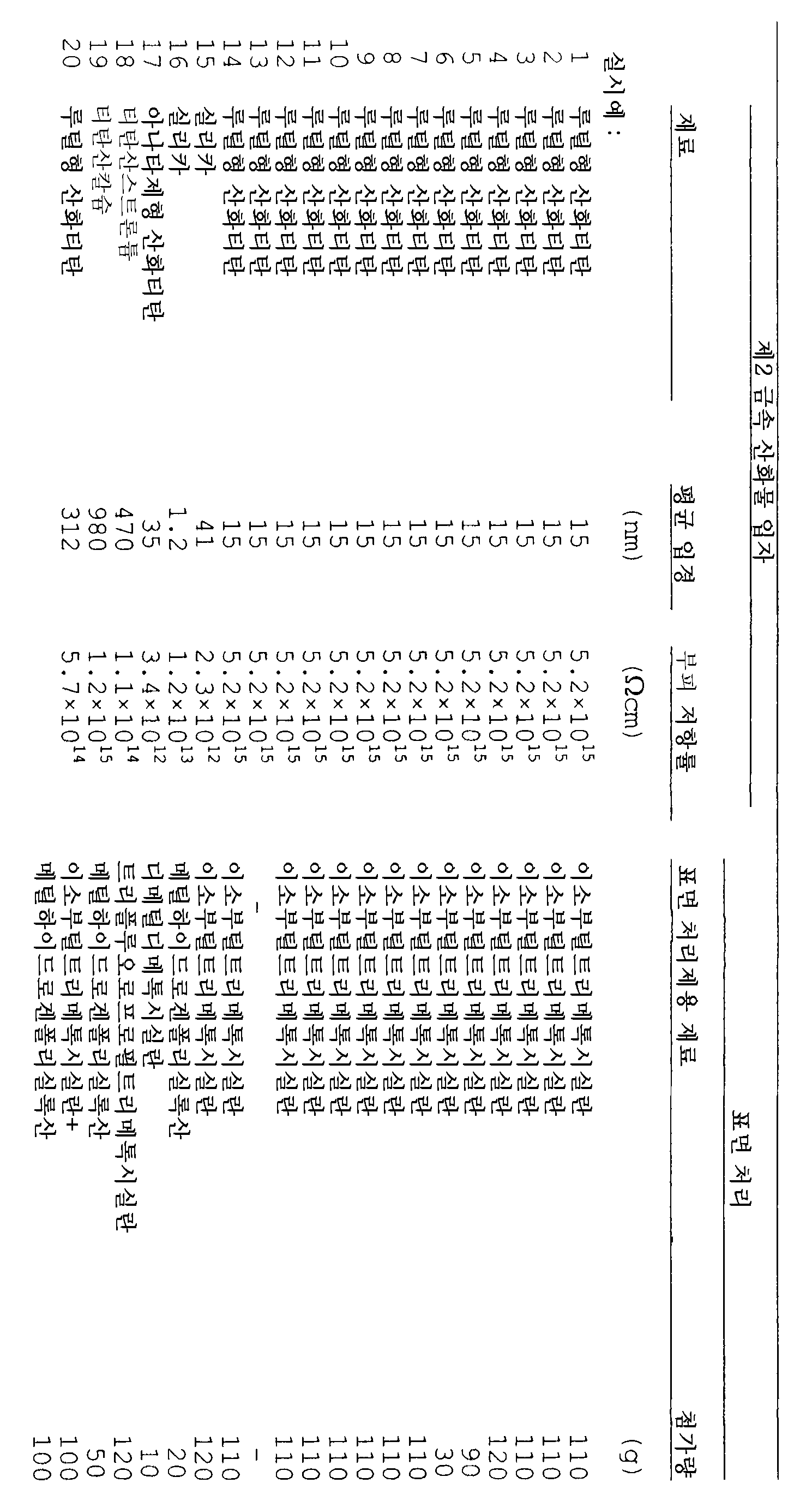


본 발명에 의하면, 대전 부재에 인가하는 전압이 직류 전압만인 전자 사진 장치에 이용되는 경우에도, 화상 결함(특히 C-세트 화상)이 없는 양호한 화상을 출력할 수 있는 대전 부재를 제공할 수 있으며, 이러한 대전 부재를 갖는 프로세스 카트리지 및 전자 사진 장치를 또한 제공할 수 있다. According to the present invention, even when the voltage applied to the charging member is used in an electrophotographic apparatus having only a direct current voltage, a charging member capable of outputting a good image without an image defect (especially a C-set image) can be provided. It is also possible to provide a process cartridge and an electrophotographic apparatus having such a charging member.
Claims (17)
Applications Claiming Priority (4)
| Application Number | Priority Date | Filing Date | Title |
|---|---|---|---|
| JP2004229504 | 2004-08-05 | ||
| JPJP-P-2004-00229504 | 2004-08-05 | ||
| JP2005154894A JP5183018B2 (en) | 2004-08-05 | 2005-05-27 | Charging member, process cartridge, and electrophotographic apparatus |
| JPJP-P-2005-00154894 | 2005-05-27 |
Publications (2)
| Publication Number | Publication Date |
|---|---|
| KR20060049278A KR20060049278A (en) | 2006-05-18 |
| KR100689140B1 true KR100689140B1 (en) | 2007-03-08 |
Family
ID=35219325
Family Applications (1)
| Application Number | Title | Priority Date | Filing Date |
|---|---|---|---|
| KR1020050071259A KR100689140B1 (en) | 2004-08-05 | 2005-08-04 | Charging member, process cartridge, and electrophotographic apparatus |
Country Status (4)
| Country | Link |
|---|---|
| US (1) | US7366448B2 (en) |
| EP (1) | EP1624347B1 (en) |
| JP (1) | JP5183018B2 (en) |
| KR (1) | KR100689140B1 (en) |
Families Citing this family (22)
| Publication number | Priority date | Publication date | Assignee | Title |
|---|---|---|---|---|
| US7283771B2 (en) * | 2004-09-17 | 2007-10-16 | Canon Kasei Kabushiki Kaisha | Charging roller |
| KR100893985B1 (en) * | 2004-12-28 | 2009-04-20 | 캐논 가부시끼가이샤 | Charging member, process cartridge and electrophotographic apparatus |
| CN101379598B (en) * | 2006-02-03 | 2010-06-23 | Jsr株式会社 | Chemical mechanical polishing pad |
| KR20100129344A (en) | 2006-02-28 | 2010-12-08 | 캐논 가부시끼가이샤 | Charging member, process cartridge, and electrophotographic apparatus |
| CN101443708A (en) * | 2006-05-18 | 2009-05-27 | 三菱化学株式会社 | Coating liquid for undercoating layer formation, process for producing coating liquid for undercoating layer formation, electrophotographic photoreceptor, apparatus for image formation, and electropho |
| JP5239135B2 (en) * | 2006-08-14 | 2013-07-17 | 株式会社リコー | Conductive member, process cartridge, and image forming apparatus |
| JP5234383B2 (en) * | 2006-12-28 | 2013-07-10 | 株式会社リコー | Image forming apparatus and process cartridge |
| US7738824B2 (en) * | 2008-07-29 | 2010-06-15 | Xerox Corporation | Treated carbon black intermediate transfer components |
| CN102203683B (en) * | 2008-10-31 | 2014-04-16 | 佳能株式会社 | Charging member, process cartridge, and electrophotographic apparatus |
| CN102203682B (en) * | 2008-10-31 | 2014-03-12 | 佳能株式会社 | Charging roller, process cartridge and electrophotographic device |
| WO2011045916A1 (en) * | 2009-10-15 | 2011-04-21 | キヤノン株式会社 | Electrificating member and electrophotographic device |
| WO2011077635A1 (en) * | 2009-12-22 | 2011-06-30 | キヤノン株式会社 | Charging member, electrophotographic device and process cartridge |
| WO2012049814A1 (en) * | 2010-10-15 | 2012-04-19 | キヤノン株式会社 | Electrification member |
| CN103328561B (en) * | 2011-01-21 | 2014-12-10 | 佳能株式会社 | Electrically conductive rubber elastomer, charging member, and electrophotographic apparatus |
| CN103597411B (en) * | 2011-06-30 | 2015-09-23 | 佳能株式会社 | The manufacture method of charging member, charging member and electronic photographing device |
| JP6000989B2 (en) * | 2012-02-06 | 2016-10-05 | キヤノン株式会社 | Charging member and electrophotographic apparatus |
| JP6067632B2 (en) | 2013-11-21 | 2017-01-25 | 三星電子株式会社Samsung Electronics Co.,Ltd. | Charging member |
| WO2016018366A1 (en) | 2014-07-31 | 2016-02-04 | Hewlett-Packard Development Company, L.P. | Resistive film with ductile particles |
| WO2016018379A1 (en) | 2014-07-31 | 2016-02-04 | Hewlett-Packard Development Company, L.P. | Inner resistive film with ductile particles and outer resistive film |
| JP6164239B2 (en) * | 2015-03-20 | 2017-07-19 | 富士ゼロックス株式会社 | Charging member, process cartridge, and image forming apparatus |
| JP6691645B2 (en) * | 2015-11-27 | 2020-05-13 | ヒューレット−パッカード デベロップメント カンパニー エル.ピー.Hewlett‐Packard Development Company, L.P. | Charging member |
| WO2022081148A1 (en) * | 2020-10-14 | 2022-04-21 | Hewlett-Packard Development Company, L.P. | Charging member having two surface layers |
Citations (4)
| Publication number | Priority date | Publication date | Assignee | Title |
|---|---|---|---|---|
| JPH1048913A (en) * | 1996-08-02 | 1998-02-20 | Canon Inc | Electrification member and electrophotographic device using it |
| KR20030014261A (en) * | 2000-06-14 | 2003-02-15 | 스미토모덴코파인폴리머 가부시키가이샤 | Roller producing method |
| JP2003162106A (en) * | 2001-11-29 | 2003-06-06 | Mikuni Color Ltd | Electrically conductive material for electrically conductive roll, dispersed liquid containing the same, electrically conductive roll and coating composition for electrically conductive roll |
| JP2004126064A (en) * | 2002-09-30 | 2004-04-22 | Fuji Xerox Co Ltd | Conductive member |
Family Cites Families (11)
| Publication number | Priority date | Publication date | Assignee | Title |
|---|---|---|---|---|
| JP3313942B2 (en) | 1994-06-22 | 2002-08-12 | キヤノン株式会社 | Magnetic particles for charging member, electrophotographic apparatus using the same, process cartridge and image forming method |
| JPH11119514A (en) * | 1997-10-16 | 1999-04-30 | Ricoh Co Ltd | Electrostatic charging roller |
| JPH11231614A (en) | 1998-02-18 | 1999-08-27 | Fuji Xerox Co Ltd | Charge imparting member, transfer device using the same and image forming device |
| JP3852231B2 (en) | 1998-12-14 | 2006-11-29 | 富士ゼロックス株式会社 | Charge-related component of image forming apparatus and image forming apparatus using the same |
| JP2000330359A (en) * | 1999-05-19 | 2000-11-30 | Canon Inc | Electrifying member and image forming device |
| JP3875066B2 (en) * | 2001-10-29 | 2007-01-31 | 花王株式会社 | Toner production method |
| JP4047057B2 (en) | 2002-04-19 | 2008-02-13 | キヤノン株式会社 | Method for manufacturing charging member |
| JP4047056B2 (en) * | 2002-04-19 | 2008-02-13 | キヤノン株式会社 | Conductive member, image forming apparatus using the same, and process cartridge |
| US6962746B2 (en) * | 2002-04-19 | 2005-11-08 | Canon Kasei Kabushiki Kaisha | Conductive member, and process cartridge and electrophotographic apparatus which make use of the same |
| JP4442805B2 (en) * | 2002-11-29 | 2010-03-31 | シンジーテック株式会社 | Conductive roll |
| JP4468062B2 (en) * | 2004-04-30 | 2010-05-26 | キヤノン株式会社 | Charging roller |
-
2005
- 2005-05-27 JP JP2005154894A patent/JP5183018B2/en not_active Expired - Fee Related
- 2005-06-21 US US11/156,773 patent/US7366448B2/en active Active
- 2005-08-04 EP EP05017566.0A patent/EP1624347B1/en not_active Expired - Fee Related
- 2005-08-04 KR KR1020050071259A patent/KR100689140B1/en not_active IP Right Cessation
Patent Citations (4)
| Publication number | Priority date | Publication date | Assignee | Title |
|---|---|---|---|---|
| JPH1048913A (en) * | 1996-08-02 | 1998-02-20 | Canon Inc | Electrification member and electrophotographic device using it |
| KR20030014261A (en) * | 2000-06-14 | 2003-02-15 | 스미토모덴코파인폴리머 가부시키가이샤 | Roller producing method |
| JP2003162106A (en) * | 2001-11-29 | 2003-06-06 | Mikuni Color Ltd | Electrically conductive material for electrically conductive roll, dispersed liquid containing the same, electrically conductive roll and coating composition for electrically conductive roll |
| JP2004126064A (en) * | 2002-09-30 | 2004-04-22 | Fuji Xerox Co Ltd | Conductive member |
Also Published As
| Publication number | Publication date |
|---|---|
| US20060029428A1 (en) | 2006-02-09 |
| KR20060049278A (en) | 2006-05-18 |
| EP1624347A3 (en) | 2008-01-30 |
| US7366448B2 (en) | 2008-04-29 |
| EP1624347A2 (en) | 2006-02-08 |
| JP2006072318A (en) | 2006-03-16 |
| JP5183018B2 (en) | 2013-04-17 |
| EP1624347B1 (en) | 2014-11-26 |
Similar Documents
| Publication | Publication Date | Title |
|---|---|---|
| KR100689140B1 (en) | Charging member, process cartridge, and electrophotographic apparatus | |
| JP4455454B2 (en) | Charging member, process cartridge, and electrophotographic apparatus | |
| KR100572285B1 (en) | Conductive member, electrophotographic apparatus and process cartridge using the same | |
| JP2010086003A (en) | Charging member, process cartridge, and electrophotographic apparatus | |
| JP2008276023A (en) | Charging member, process cartridge and electrophotographic image forming apparatus | |
| JP2008276024A (en) | Charging member, process cartridge and electrophotographic device | |
| JP2014134777A (en) | Electrophotographic member, process cartridge and electrophotographic device | |
| JP2007093937A (en) | Charging member, process cartridge and electrophotographic apparatus | |
| JP5121438B2 (en) | Charging member, process cartridge, and electrophotographic apparatus | |
| JP5110985B2 (en) | Contact charging member, process cartridge, and electrophotographic image forming apparatus | |
| CN100416421C (en) | Charging member, process cartridge, and electrophotographic apparatus | |
| JP2001140854A (en) | Semiconductive roller and image forming device | |
| JP2007101864A (en) | Charging component and electrophotographic system | |
| JP5058691B2 (en) | Electrophotographic charging member, process cartridge, and electrophotographic apparatus | |
| JP2004306519A (en) | Conductive member | |
| JP2005037931A (en) | Electrostatic chargeable material, process cartridge, and electrophotographic system | |
| JP2014089415A (en) | Charging member for electrophotography, process cartridge, and electrophotographic device | |
| JP2007187900A (en) | Conductive roller for electrophotography | |
| JP4713900B2 (en) | Manufacturing method of conductive member and conductive member for electrophotography | |
| JP2006163147A (en) | Electrifying roller, electrifying method, process cartridge and electrophotographic device | |
| JP4217578B2 (en) | Charging member, process cartridge and electrophotographic apparatus using the same | |
| JP2003316110A (en) | Conductive member, and image forming device and process cartridge using the same | |
| JP2006113377A (en) | Electrifying member, process cartridge and electrophotographic apparatus using electrifying member | |
| JP2004245944A (en) | Conductive member | |
| JP6801197B2 (en) | Charging member, charging device, process cartridge, and image forming device |
Legal Events
| Date | Code | Title | Description |
|---|---|---|---|
| A201 | Request for examination | ||
| E902 | Notification of reason for refusal | ||
| E701 | Decision to grant or registration of patent right | ||
| GRNT | Written decision to grant | ||
| FPAY | Annual fee payment |
Payment date: 20130201 Year of fee payment: 7 |
|
| FPAY | Annual fee payment |
Payment date: 20140204 Year of fee payment: 8 |
|
| FPAY | Annual fee payment |
Payment date: 20150119 Year of fee payment: 9 |
|
| LAPS | Lapse due to unpaid annual fee |