KR100587218B1 - Tablet feeder - Google Patents
Tablet feeder Download PDFInfo
- Publication number
- KR100587218B1 KR100587218B1 KR1020000001454A KR20000001454A KR100587218B1 KR 100587218 B1 KR100587218 B1 KR 100587218B1 KR 1020000001454 A KR1020000001454 A KR 1020000001454A KR 20000001454 A KR20000001454 A KR 20000001454A KR 100587218 B1 KR100587218 B1 KR 100587218B1
- Authority
- KR
- South Korea
- Prior art keywords
- rotor
- tablet
- storage case
- discharge path
- Prior art date
Links
Images


Classifications
-
- B—PERFORMING OPERATIONS; TRANSPORTING
- B65—CONVEYING; PACKING; STORING; HANDLING THIN OR FILAMENTARY MATERIAL
- B65G—TRANSPORT OR STORAGE DEVICES, e.g. CONVEYORS FOR LOADING OR TIPPING, SHOP CONVEYOR SYSTEMS OR PNEUMATIC TUBE CONVEYORS
- B65G47/00—Article or material-handling devices associated with conveyors; Methods employing such devices
- B65G47/02—Devices for feeding articles or materials to conveyors
- B65G47/04—Devices for feeding articles or materials to conveyors for feeding articles
- B65G47/12—Devices for feeding articles or materials to conveyors for feeding articles from disorderly-arranged article piles or from loose assemblages of articles
- B65G47/14—Devices for feeding articles or materials to conveyors for feeding articles from disorderly-arranged article piles or from loose assemblages of articles arranging or orientating the articles by mechanical or pneumatic means during feeding
- B65G47/1407—Devices for feeding articles or materials to conveyors for feeding articles from disorderly-arranged article piles or from loose assemblages of articles arranging or orientating the articles by mechanical or pneumatic means during feeding the articles being fed from a container, e.g. a bowl
- B65G47/1442—Devices for feeding articles or materials to conveyors for feeding articles from disorderly-arranged article piles or from loose assemblages of articles arranging or orientating the articles by mechanical or pneumatic means during feeding the articles being fed from a container, e.g. a bowl by means of movement of the bottom or a part of the wall of the container
- B65G47/1457—Rotating movement in the plane of the rotating part
-
- B—PERFORMING OPERATIONS; TRANSPORTING
- B65—CONVEYING; PACKING; STORING; HANDLING THIN OR FILAMENTARY MATERIAL
- B65B—MACHINES, APPARATUS OR DEVICES FOR, OR METHODS OF, PACKAGING ARTICLES OR MATERIALS; UNPACKING
- B65B35/00—Supplying, feeding, arranging or orientating articles to be packaged
- B65B35/06—Separating single articles from loose masses of articles
- B65B35/08—Separating single articles from loose masses of articles using pocketed conveyors
-
- G—PHYSICS
- G07—CHECKING-DEVICES
- G07F—COIN-FREED OR LIKE APPARATUS
- G07F11/00—Coin-freed apparatus for dispensing, or the like, discrete articles
- G07F11/02—Coin-freed apparatus for dispensing, or the like, discrete articles from non-movable magazines
- G07F11/44—Coin-freed apparatus for dispensing, or the like, discrete articles from non-movable magazines in which magazines the articles are stored in bulk
-
- G—PHYSICS
- G07—CHECKING-DEVICES
- G07F—COIN-FREED OR LIKE APPARATUS
- G07F17/00—Coin-freed apparatus for hiring articles; Coin-freed facilities or services
- G07F17/0092—Coin-freed apparatus for hiring articles; Coin-freed facilities or services for assembling and dispensing of pharmaceutical articles
Abstract
본 발명은 로터를 회전시키는 것에 의해 저장 케이스에 있는 정제가 배출되는 타입의 정제 공급기에 관한 것이다. 본 발명은 지지 베이스로부터 저장 케이스가 장착 또는 장착 해제될 때, 로터의 작은 회전에 의해 정제가 비의도적으로 배출되는 것을 방지할 수 있다. 저장 케이스는 지지 베이스에 분리 가능하게 장착되어 있다. 로터는 회전 샤프트에 대하여 회전 가능하도록 저장 케이스의 바닥부에 장착되어 있고, 그 바닥 단부에서 회전 기어를 통하여 모터와 연결되어 있다. 복수의 소형 자석이 바닥부의 외주에 제공되어 있고, 그리고 소형 자석은 소정의 간격을 두고 로터의 외주 상의 복수의 위치에 제공되어 있다.The present invention relates to a tablet feeder of the type in which tablets in the storage case are ejected by rotating the rotor. The present invention can prevent the tablets from being inadvertently ejected by a small rotation of the rotor when the storage case is mounted or unmounted from the support base. The storage case is detachably mounted to the support base. The rotor is mounted to the bottom of the storage case so as to be rotatable with respect to the rotary shaft, and is connected to the motor via a rotary gear at the bottom end thereof. A plurality of small magnets is provided on the outer periphery of the bottom, and the small magnets are provided at a plurality of positions on the outer periphery of the rotor at predetermined intervals.
포켓, 로터, 소형 자석, 파티션 부재, 소정 위치 제동 수단, 역회전 방지 수단Pocket, rotor, small magnet, partition member, predetermined position braking means, reverse rotation prevention means
Description
도 1은 제1 실시예의 정제 공급기에 대한 종단면도;1 is a longitudinal sectional view of the tablet feeder of the first embodiment;
도 2는 도 1의 선 II-II를 따라 취한 단면도;2 is a cross-sectional view taken along the line II-II of FIG. 1;
도 3은 도 1의 선 III-III를 따라 취한 단면도;3 is a sectional view taken along line III-III of FIG. 1;
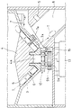
도 4는 제2 실시예의 정제 공급기에 대한 종단면도;4 is a longitudinal sectional view of the tablet feeder of the second embodiment;
도 5는 도 4의 선 V-V를 따라 취한 단면도;5 is a cross-sectional view taken along the line V-V of FIG. 4;
도 6a는 도 4의 선 VI-VI를 따라 취한 단면도;6A is a cross sectional view taken along the line VI-VI of FIG. 4;
도 6b는 도 6a에 대한 부분 확대 단면도;FIG. 6B is a partially enlarged cross-sectional view of FIG. 6A; FIG.
도 7은 제3 실시예의 정제 공급기에 대한 종단면도;7 is a longitudinal sectional view of the tablet feeder of the third embodiment;
도 8은 도 7의 정제 공급기의 회전 샤프트 바닥부에 인접한 부분에 대한 부분 확대 단면도;FIG. 8 is a partially enlarged cross-sectional view of a portion adjacent the bottom of the rotating shaft of the tablet feeder of FIG.
도 9는 도 8의 선 IX-IX를 따라 취한 단면도;9 is a cross-sectional view taken along line IX-IX of FIG. 8;
도 10은 도 8의 선 X-X를 따라 취한 단면도;10 is a cross-sectional view taken along the line X-X of FIG. 8;
도 11은 제4 실시예의 정제 공급기에 대한 종단면도; 그리고 11 is a longitudinal sectional view of the tablet feeder of the fourth embodiment; And
도 12는 도 11의 선 XII-XII를 따라 취한 단면도이다.12 is a cross-sectional view taken along the line XII-XII in FIG. 11.
본 발명은 캡슐을 포함하여 정제를 공급하기 위한 정제 공급기의 공급 메카니즘의 개선에 관한 것이다.The present invention is directed to an improvement in the feeding mechanism of a tablet feeder for supplying tablets, including capsules.
정제 포장 장치로 정제를 공급하기 위한 종래의 정제 공급기는 일본국 특개평 9-323702호에 개시되어 있다. 정제 공급기는 정제 저장 케이스의 바닥부에 회전 가능하게 장착된 로터를 가지고 있으며 저장 케이스는 로터를 구동하기 위한 모터가 장착되어 있는 지지 베이스에 대하여 수평방향으로 분리 가능하게 되어 있다. A conventional tablet feeder for supplying tablets to a tablet packaging apparatus is disclosed in Japanese Patent Laid-Open No. 9-323702. The tablet feeder has a rotor rotatably mounted at the bottom of the tablet storage case, the storage case being detachable in a horizontal direction with respect to a support base on which a motor for driving the rotor is mounted.
저장 케이스의 바닥부에는 오목부가 형성되어 있고, 원뿔형인 로터가 그 내로 수용되며, 로터는 이의 회전 축선에 대하여 회전 가능하도록 원뿔형으로 되어 있다. 바닥부에는, 아이들러 기어가 장착된다. 저장 케이스가 지지 베이스에 장착될 때, 지지 베이스에 있는 모터의 출력 샤프트의 단부에 있는 구동 기어는 아이들러 기어와 맞물리기에 적합하게 되어 있다. 지지 베이스에는 정제를 비스듬하게 하향으로 배출하기 위한 배출 경로가 제공되어 있다. 로터는 이의 외주를 따라 정제가 투하되는 복수의 포켓을 가지고 있다. 각각의 포켓이 배출 경로와 맞추어질 때, 포켓에 있는 정제는 투하되고 하향으로 배출된다. A recess is formed in the bottom of the storage case, and a conical rotor is accommodated therein, and the rotor is conical so as to be rotatable about its rotation axis. At the bottom, an idler gear is mounted. When the storage case is mounted to the support base, the drive gear at the end of the output shaft of the motor in the support base is adapted to engage the idler gear. The support base is provided with a discharge path for discharging the tablet obliquely downward. The rotor has a plurality of pockets through which tablets are dispensed along its periphery. As each pocket is fitted with the discharge path, the tablets in the pocket are dropped and discharged downwards.
정제 공급기는 로터를 회전시킴으로써 포켓에 있는 정제가 한 개씩 배분되도록 제어되고 배분된 수는 기록된다. 소정된 정제의 개수에 도달하면, 모터를 정지시킴으로써 로터가 정지된다. 따라서, 배분 속도가 로터의 속도에 의해 증가되면, 센서 감지에 의해 정제의 개수가 소정된 개수에 도달하여 로터가 급정지될 때, 로 터는 정지 신호가 생성된 정확한 위치에서 정지하지 않고 이의 관성 때문에 이러한 위치로부터 소량 회전한다. The tablet feeder is controlled to distribute the tablets in the pocket one by one by rotating the rotor and the number dispensed is recorded. When the predetermined number of tablets has been reached, the rotor is stopped by stopping the motor. Therefore, if the distribution speed is increased by the speed of the rotor, when the number of tablets reaches a predetermined number by sensor sensing and the rotor is stopped quickly, the rotor does not stop at the exact position where the stop signal is generated and because of its inertia Rotate a small amount from the position.
따라서, 마지막으로 배분된 정제를 바로 따르는 정제를 수용하는 포켓이 배출 경로의 위치를 근접하게 접근하여 정지되면, 포켓은 배출 경로의 바로 위의 위치로 회전하지는 않지만, 정제의 종류, 회전 속도, 그리고 기타 여러 조건들에 따라, 이러한 위치에 매우 근접한 위치에서 정지할 수 있다. Thus, if the pocket containing the tablet immediately following the last dispensed tablet stops in close proximity to the position of the discharge path, the pocket does not rotate to a position just above the discharge path, but the type of tablet, the speed of rotation, and Depending on other conditions, it may stop at a location very close to this location.
이러한 문제를 극복하기 위하여, 상기 공보에 개시된 정제 공급기는 저장 케이스가 분리될 때, 로터의 회전을 방지하기 위한 회전 방지 수단을 정제 저장 케이스의 하부 바닥부에 가지고 있고, 이것은 로터의 바닥부에 있는 회전 샤프트 상에 제공된 구동 기어를 맞물림함으로써 수행된다. In order to overcome this problem, the tablet feeder disclosed in the above publication has anti-rotation means at the bottom bottom of the tablet storage case to prevent rotation of the rotor when the storage case is separated, which is located at the bottom of the rotor. By engaging the drive gear provided on the rotary shaft.
하지만, 종래의 정제 공급기의 회전 방지 수단은, 지지 베이스로부터 저장 케이스가 분리될 때 회전을 기계적으로 방지하는 수단이기 때문에, 이러한 수단은 로터를 원하는 위치에서 센서에 의한 정제 감지에 기반한 정지 신호에 의해 바로 정지시킬 수 없다. 따라서, 그 다음 정제의 포켓은 배출 경로와 매우 근접한 위치에 정지할 수 있다. However, since the anti-rotation means of the conventional tablet feeder is a means of mechanically preventing rotation when the storage case is separated from the support base, such means is provided by the stop signal based on the tablet detection by the sensor at the desired position of the rotor. You can't stop it right away. Thus, the pocket of the tablet can then stop at a position very close to the discharge path.
또한, 회전 방지 수단은 저장 케이스가 분리될 때만 로터의 회전을 방지할 수 있다. 회전 방지 수단의 맞물림이 해제되어 로터가 전방 또는 후방으로 소량 회전하면, 즉 정제 공급기가 또 하나의 정제 공급기로 교체되고 저장 케이스가 재장착될 때 기어의 1개의 톱니만큼 회전하면, 문제가 되는 포켓은 배출 경로에 매우 근접한 위치에서 정지될 수 있다. 따라서, 포켓은 배출 경로와 맞추어질 수 있다. 따라서, 정제는 비의도적으로 투하될 수 있다.In addition, the rotation preventing means can prevent the rotation of the rotor only when the storage case is separated. Pockets in question when the anti-rotation means disengage so that the rotor rotates a small amount forward or backward, i.e. when the tablet feeder is replaced by another tablet feeder and rotated by one tooth of the gear when the storage case is remounted Can be stopped at a position very close to the discharge path. Thus, the pocket can be fitted with the discharge path. Thus, tablets may be inadvertently released.
본 발명의 목적은 로터의 회전이 정지될 때, 로터가 간단한 구조를 가진 제동 수단에 의해 소정의 위치에서 정지되기에 적합하게 된 정제 공급기를 제공하여서, 이에 따라, 저장 케이스가 장착 또는 장착 해제될 때 정제의 비의도적인 투하를 방지하는 것이다. It is an object of the present invention to provide a tablet feeder in which the rotor is adapted to be stopped at a predetermined position by a braking means having a simple structure when the rotation of the rotor is stopped, whereby the storage case can be mounted or demounted. When the tablet is to prevent unintentional release.
본 발명의 또 하나의 목적은 로터가 역방향으로 회전하는 것을 방지할 수 있는 정제 공급기를 제공하여서, 이에 따라, 파티션 부재의 손상을 방지하는 것이다.Another object of the present invention is to provide a tablet feeder which can prevent the rotor from rotating in the reverse direction, thereby preventing damage to the partition member.
본 발명에 따르면, 바닥부를 가지고 있는 정제 저장 케이스, 정제 저장 케이스의 바닥부에 회전 가능하게 장착된 로터, 그리고 로터를 구동하기 위한 모터를 포함하고 있으며, 로터에는 정제를 수용하기 위한 복수의 포켓이 형성되어 있고, 그리고 각각의 포켓이 로터 밑에 제공된 배출 경로와 일치될 때, 정제가 배출될 수 있도록 되어 있는 정제 공급기에 있어서, 로터를 소정된 위치에서 정지시키도록 소정 위치 제동 수단이 제공되어 있는 것을 특징으로 하는 정제 공급기가 제공된다.According to the present invention, there is provided a tablet storage case having a bottom, a rotor rotatably mounted at the bottom of the tablet storage case, and a motor for driving the rotor, wherein the rotor has a plurality of pockets for receiving tablets. In a tablet feeder configured to allow tablets to be discharged when each pocket coincides with a discharge path provided under the rotor, the predetermined position braking means being provided to stop the rotor at the predetermined position. A tablet feeder is provided that features.
본 발명에 따라, 정제가 저장되는 저장 케이스는 지지 테이블에 분리 가능하게 장착되고, 그리고 정제는 배출 경로를 통하여 배출되어 약제 포장 장치로 공급된다. 이러한 정제 공급 작용은 로터를 회전시켜서 로터의 외면에 형성된 포켓이 배출 경로와 일치될 때마다 하나의 정제를 배출함으로써 수행된다. 이러한 정제 공급 작용 자체는 종래의 정제 공급기와 동일하다. According to the invention, the storage case in which the tablets are stored is detachably mounted to the support table, and the tablets are discharged through the discharge path and supplied to the pharmaceutical packaging device. This tablet feeding action is performed by rotating the rotor to discharge one tablet each time a pocket formed on the outer surface of the rotor coincides with the discharge path. This tablet feeding action itself is the same as a conventional tablet feeder.
그러나, 정제 공급기의 정제를 보충하기 위하여 지지 테이블로부터 저장 케이스가 장착 해제될 때, 정제가 배출 경로 내로 투하되는 위치 바로 전에서 로터가 정지되면, 회전 기어들의 맞물림에 의한 작은 이동량 때문에 로터는 회전하는 경향이 있어서, 정제가 비의도적으로 투하될 수 있다. 본 발명의 정제 공급기에서는 이러한 우발 사고가 발생되지 않는다. However, when the storage case is dismounted from the support table to replenish the tablets of the tablet feeder, if the rotor is stopped just before the location where the tablets are dropped into the discharge path, the rotor rotates due to the small amount of movement due to the engagement of the rotary gears. As such, tablets may be inadvertently released. This accident does not occur in the tablet feeder of the present invention.
로터가 정지되면, 소정 위치 제동 수단에 의해 로터에는 이를 소정된 위치에서 정지시키도록 제동력이 적용된다. 일단 로터가 정지되면, 제동력을 대항하여 로터를 회전시키기에 충분한 회전력이 적용되기 전에는 로터가 회전하지 않는다. 따라서, 로터는, 저장 케이스가 장착 해제되는 동안 회전 기어의 맞물림의 이동에 의해 또는 누군가 로터를 의도적으로 회전시키려고 하는 것에 의해 쉽게 회전될 수 없다. 따라서, 정제는 절대로 비의도적으로 투하되지 않는다. When the rotor is stopped, a braking force is applied to the rotor by the predetermined position braking means to stop it at the predetermined position. Once the rotor is stopped, the rotor does not rotate until sufficient torque is applied to rotate the rotor against the braking force. Thus, the rotor cannot be easily rotated by the movement of the engagement of the rotary gear while the storage case is dismounted or by someone intentionally attempting to rotate the rotor. Thus, tablets are never inadvertently released.
또한, 포켓에서 정제를 분할하기 위한 위스커(whisker) 형 탄성 부재를 포함하고 있는 파티션 부재가 배출 경로를 면하고 있는 위치에서 바닥부에 고정되어 있으면, 바람직하게, 역회전 방지 수단이 로터의 회전 샤프트의 바닥부에 장착된다. 이것은 로터의 역방향 회전으로 인하여 위스커 형 탄성 부재가 손상되는 것을 방지한다.In addition, if the partition member including a whisker-like elastic member for dividing the tablet in the pocket is fixed to the bottom at a position facing the discharge path, the reverse rotation prevention means is preferably provided with a rotating shaft of the rotor. It is mounted on the bottom of the. This prevents the whisker type elastic member from being damaged due to the reverse rotation of the rotor.
본 발명의 장점 및 목적은 첨부된 도면을 참조하여 하기 상세 설명으로부터 명확해질 것이다. Advantages and objects of the present invention will become apparent from the following detailed description with reference to the accompanying drawings.
본 발명의 실시예가 하기 설명되어 있다. Examples of the present invention are described below.
도 1은 제1 실시예의 정제 공급기의 단면도를 도시하고 있다. 도시된 바와 같이, 이것은 정제 저장 케이스(1) 및 지지 베이스(2)를 결합하여 이루어진다. 정제 저장 케이스는 소정된 갭을 갖고 회전 샤프트(4a)를 통하여 회전될 수 있는 원통형 로터(4)가 회전 가능하게 장착되어 있는 오목부(3a)로서 형성된 내부 바닥부(3)를 가지고 있다. 로터(4)는 짧은 원뿔형 상단부 그리고 각도상으로 간격 두고 배열된 수직 안내 홈 형상의 복수의 포켓을 외면에 가지고 있는 원통형 하부를 갖추고 있다. 각각의 포켓은 복수(3개 내지 4개)의 정제(T)를 수용할 수 있다. 부재번호(1a)는 저장 케이스(1)의 덮개 플레이트이다. 1 shows a cross-sectional view of a tablet feeder of the first embodiment. As shown, this is achieved by combining the
각각의 포켓의 상단부는 넓혀져 있어서 정제가 쉽게 수용될 수 있다. 파티션 홈(6)은 로터(4)의 바닥부에 인접한 외주면의 원통형 부분의 원주 전체를 걸쳐 뻗어 있다. 하기 설명되어 있는 파티션 부재(7)는 정제를 나눌 수 있도록 파티션 홈(16) 내에 수용된다. 로터(4)의 회전 샤프트(4a)는 바닥부(3)의 바닥 플레이트를 통하여 하향으로 뻗어 있고, 또 다른 회전 기어(9b)와 맞물리는 회전 기어(9a)를 그 바닥부에 수용하고 있다. The upper end of each pocket is widened so that tablets can be easily accommodated. The
로터(4)의 외주 상에는 동일한 각도상의 간격으로 복수의 소형 자석(10b)이 제공되어 있다. 바닥부(3)의 수직 벽의 외주 상에도 복수(도시된 실시예에서는 2개)의 소형 자석(10a)이 상응하는 간격으로 제공되어 있다. 상응하는 소형 자석(10a, 10b) 쌍은 소정된 위치에서 로터(4)를 정지시키는 제동 수단을 형성하고 있다. 제동 수단(10)은 적어도 하나의 소형 자석(10a)과 복수의 소형 자석(10b)(또는 자성체)의 조합체 또는 복수의 소형 자석(10a)(또는 외주 전체를 걸쳐 상응하는 간격으로 배열된 자성체)와 적어도 하나의 소형 자석(10b)의 조합체일 수 있다. On the outer circumference of the
소형 자석(10a)은 동일한 자극성을 가지고 설치된다. 소형 자석(10b)은 상기 자석과 반대의 자극성을 갖는다. 그러나, 소형 자석(10a 또는 10b)이 자성체라면, 짝을 이루는 자석들은 동일한 자극성을 가지고 있지 않아도 좋다. 소형 자석들(10a 또는 10b) 사이의 간격은 바람직하게 로터(4)의 외주 상에 있는 포켓(5)의 간격과 동일하다. 이러한 배열로, 정지 신호에 의해 로터(4)의 회전 구동력이 없어지는 동시에 로터는 이 위치에서 가장 근접한 제동 수단의 인력에 의해 즉시 정지될 수 있다. The
도 3에 도시된 바와 같이, 지지 베이스(2) 상에 안내 플레이트(11)가 제공된다. 이의 양단부에는 저장 케이스(1)를 맞물기 위한 아암(11a)이 제공되어 있다. 각각의 아암(11a)에는 오목부가 형성되어 있다. 반면에, 저장 케이스(1)의 내부 바닥부 상에는 아암(11a)을 샌드위치하기 위한 돌출부(1B)가 제공되어 있다. 아암의 오목부에 돌출부(1B)를 맞물리게 함으로써, 저장 케이스(1)는 지지 베이스(2)와 맞물린다. As shown in FIG. 3, a
구동 기어(12)는 안내 플레이트(11)의 하나의 모서리에 제공되어 있다. 이의 회전 축선을 따라, 지지 베이스(2)에 있는 모터(13)로부터의 파워가 전달된다. 기어(12)는 저장 케이스(1)의 회전 기어(9b)와 맞물려서 또 하나의 회전 기어(9a)를 통하여 로터(4)를 회전시킨다. 안내 플레이트(11)에는 배출 경로의 개구가 제공되어 있다. 배출 경로(8)의 둘레면의 적절한 위치에는 정제의 통과를 감지하기 위한 센서(S)(도 1)가 제공되어 있다. The
더하여, 배출 경로(8)에 상응하는 위치에서, 내부 바닥 플레이트(3)의 수직 벽을 통하여 뻗도록 파티션 부재(7)가 제공되어 있다. 파티션 부재(7)는, 위스커 형 탄성 부재(7a)가 지지 아암(7b)(도 2)에 삽입고정되어 있는 치솔 형태로 형성되어 있다. 아암 베이스는 수직 벽에 고정되어 있다. 위스커 형 탄성 부재(7a)는 곡선형이며 로터(4)의 회전 방향으로 방사상 방향으로 소량 경사진 상태로 제공되어 있다. 부재(7a)는 이들의 팁을 로터(4)의 파티션 홈(6)에 수용된 상태로 가지고 있다. 이러한 부재(7a)에 의하여, 정제(T)는 상부 및 하부 정제로 나누어진다. 하부에는, 하나의 정제만이 포켓(5)에 유지된다. In addition, at a position corresponding to the
제1 실시예의 정제 공급기는 다음과 같은 방식으로 정제를 공급한다. 덮개 플레이트(1a)가 닫힌 상태에서, 지지 베이스(1) 상에 장착된 정제 공급기의 저장 케이스(1)에 요구되는 양의 정제가 공급된 상태로 모터(13)가 회전되면, 로터(4)가 구동된다. 로터의 파티션 홈(6)에 수용되어 있는 위스커 형 탄성 부재(7a)는 접근하는 포켓(5)에 있는 정제를 나눈다. 포켓이 배출 경로(8)의 개구와 맞추어지면, 탄성 부재(7a) 밑에 있는 1개의 정제는 배출 경로(8) 내로 투하된다. The tablet feeder of the first embodiment supplies tablets in the following manner. If the
로터(4)가 더 회전하면, 위스커 형 탄성 부재(7a)는 제거된다. 따라서, 상부 정제는 이제 비어 있는 포켓(5)의 최하부 공간을 채운다. 투하된 정제의 위치의 바로 뒤(회전 방향으로 기준으로 하여)의 포켓에 있는 정제는 배출 경로(8)와 맞추어져서 투하된다. 이러한 방식으로 포켓(5)에 있는 정제는 연속적으로 배출 경로(8) 내로 투하된다. When the
따라서, 정제는 연속적으로 투하된다. 공급시 또는 정제 공급기의 점검 또는 정제를 보충하기 위하여 지지 베이스(2)로부터 저장 케이스(1)를 장착 해제하기 위하여, 로터의 회전을 정지시키도록 모터가 정지된다. 정제가 포켓에 있는 상태로, 포켓은 배출 경로(8) 바로 전의 위치에서 정지한다. 본 실시예에 있어서, 로터(4)를 위한 제동 수단(10)이 로터(4)와 바닥부(3) 사이에서 제공되어 있으므로, 포켓(5)은 배출 경로(8) 전의 소정된 위치에서 급정지한다. Thus, tablets are continuously dropped. The motor is stopped to stop the rotation of the rotor in order to dismount the
이러한 소정된 위치는, 바로 전에 정제가 배출된 위치의 포켓 다음에 있는 포켓(5)이 배출 경로(8)에 도달하지 못하게 소정된 거리를 두고 정지하는 위치이다. 따라서, 정제가 배출된 포켓(5)이 배출 경로(8)를 지나기 전 또는 포켓이 배출 경로를 지난 바로 후, 로터(4)가 정지하도록 정지 신호는 생성된다. 정지 신호는, 배출 경로(8)의 소정된 간격인 이러한 위치에서 제동 수단(10)으로부터의 유인력이 효력이 있는 간격 영역 내를 그 다음 포켓(5)이 벗어나 전진하지 않는 타이밍으로 생성된다. 따라서, 로터(4)는 유인력에 의해 정지된다. This predetermined position is the position at which the
하지만, 로터(4)가 관성 때문에 소정된 위치로부터 어느 정도 전진한다 하더라도, 그 다음 포켓을 소정된 위치에 정지시키도록 로터는 제동 수단(10)의 유인력에 의해 다시 뒤로 유인될 것이다. 따라서, 그 다음 포켓(5)은 반드시 소정된 위치에서 정지한다. 그러나, 제동 수단(10)은 자기적 유인력에 기반한 수단이기 때문에, 기계적으로 로터(4)를 고정시키지는 않는다. 그 대신, 로터(4)의 회전은 탄력 있게 정지된다. 로터가 모터의 구동력에 의해 구동되는 동안, 이의 회전은 방해받지 않을 것이다. However, even if the
또한, 제동 수단(10)이 로터를 자기적 유인력에 의해 소정된 위치에서 정지시키기 때문에, 로터(4)가 정지 상태에 있을 때, 로터는 원활하게 회전되지 않는다. 따라서, 저장 케이스(1)를 장착 해제시켜서 이의 바닥부에서 돌출하고 있는 기어(9a, 9b)가 비의도적으로 역방향으로 회전되어도, 탄성 부재(7a)에 걸린 정제에 의해 탄성 부재가 파손될 염려는 없다.In addition, since the braking means 10 stops the rotor at a predetermined position by magnetic attraction, the rotor does not rotate smoothly when the
도 4는 제2 실시예의 정제 공급기에 대한 단면도를 도시하고 있다. 선 V-V, 선 VI-VI를 따라 취한 단면도는 도 5 및 도 6에 도시되어 있다. 본 실시예의 정제 공급기는, 저장 케이스에 있는 로터(4)가 원뿔형이라는 것에 의해 구별된다. 따라서, 다른 부분들도 약간 상이한 형상을 가지고 있다. 그러나, 제동 수단은 본 실시예에서도 채용된다. 따라서, 이들의 형상이 약간 상이해도, 동일한 기능을 가지고 있는 유사한 부재들에 대해서는 동일한 번호가 지정되어 있으며 이들에 대한 설명은 생략된다. 4 shows a cross-sectional view of the tablet feeder of the second embodiment. Cross-sectional views taken along lines V-V and VI-VI are shown in FIGS. 5 and 6. The tablet feeder of this embodiment is distinguished by the fact that the
로터는 원뿔형으로 형성되고, 바닥부(3)도 또한 로터(4)의 형상과 상응하게 원뿔형으로 형성되어 있다. 로터는 회전 축선(4a)에 대해 회전 가능하도록 수용되어 있다. 로터(4)의 외주면 상에는, 복수의 포켓(5)이 각도상의 간격을 두고 경사진 면을 따라 형성되어 있다. 파티션 홈(6)은 로터의 경사면의 중간부보다 밑에서 형성되고 둘레 전체를 걸쳐 뻗어 있다. The rotor is formed in a conical shape, and the
소형 자석(10a)은 바닥부(3)의 바깥 부분에 경사면 상의 복수의 위치(본 실시예에서는 2개)에 제공되어 있다. 복수의 소형 자석은 로터(4)의 외주면 상에 각도상의 간격을 두고 또한 제공되어 있다. 소형 자석(10b)은 포켓들 사이에 있는 것과 동일한 간격으로 포켓(5)들 사이에 제공되어 있다. 소형 자석(10a)은 또한 이러한 간격에 상응하는 간격으로 배열되어 있다. The
배출 경로(8)의 상부 개구에 상응하는 위치에서, 개구(3x)는 바닥부(3)에 형성되어 있다. 이러한 위치에서, 각각의 포켓에서 정제를 나누기 위한 파티션 부재(7)는 바닥부(3)의 외주 벽에 고정되어 있다. 파티션 부재(7)의 구조는 제1 실시예와 동일하다. 로터(4)의 각각의 포켓(5)이 정지하는 소정된 위치는 다음과 같다. At a position corresponding to the top opening of the
도 6b에 도시된 바와 같이, 로터(4)의 각각의 포켓(5)은 포켓의 전체 폭 및 다음 포켓 까지의 로터의 외주면이 개구(3x)를 거의 면하는 위치에서 정지되고, 이것이 소정된 위치이다. 또한, 정지 위치는, 소형 자석(10a, 10b)에 의해 제한되는데, 이 소형 자석은 포켓(5)이 회전하는 방향(화살표에 의해 도시됨)을 기준으로 자석의 후방 단부가 개구(3x)의 후방 단부에 소량 못 미치는 위치에서 정지되게 배열되어 있다. 개구(3x)의 폭은 바람직하게 포켓(5)의 폭보다 크다. 그러나, 도시된 실시예에서 개구의 폭은 포켓(5) 사이의 돌출부(4T)의 폭 그리고 포켓(5)의 폭(1 피치와 동일함) 전체와 일치한다. 포켓(5)의 폭과 개구(3x)의 폭 그리고 소정 위치 제동장치 사이의 관계는 다른 실시예에 적용할 수 있다. As shown in Fig. 6B, each
도 7 내지 도 10은 정제 공급기의 제3 실시예를 도시하고 있다. 본 실시예는 제2 실시예의 구조를 기반하고 있으며 일부 상이한 부분을 가지고 있다. 따라서, 기능상으로 동일한 부재에 대해서는 동일한 번호가 지정되며, 이들에 관한 설명은 생략된다. 하기 구조상의 부재는 제1 실시예에도 적용할 수 있다. 7-10 show a third embodiment of a tablet feeder. This embodiment is based on the structure of the second embodiment and has some different parts. Therefore, the same numbers are assigned to the same members functionally, and the description thereof is omitted. The following structural members can also be applied to the first embodiment.
도 8에 도시된 바와 같이, 로터(4)의 회전 샤프트(4a)의 샤프트 단부에서 바닥부(3)로부터 하향으로 돌출하고 있는 회전 기어(9a)에 인접하게, 회전 샤프트(4a)를 위한 제동 수단(10) 및 역회전 방지 수단(15)이 제공되어 있다. 소정 위치 제동 수단(10)은 적절한 위치에서 바닥부(3)의 하부에 고정된 복수(본 실시예에서는 2개)의 소형 자석(10a), 그리고 자성체의 링형 플레이트 상에 각도상의 간격을 두고 제공된 자성체의 복수의 돌출부(10b)를 포함하고 있다. As shown in FIG. 8, braking for the
자성체의 링형 플레이트는 링형 자석(10c)을 그 사이에서 샌드위치하고 있는 2개의 금속 플레이트를 포함하고 있어서, 자성체의 돌출부(10b)에 동일한 극성이 전달될 수 있게 하고, 이에 따라, 이들은 동일한 극성으로 자력이 생성된다. 이러한 극성은 하부에 고정된 소형 자석(10a)의 극성과 반대가 되도록 주어진다. 소형 자석(10a)과 자성체의 돌출부(10b) 사이의 갭은, 자성체의 플레이트의 회전을 방해하지 않으면서, 자성체의 돌출부(10b)가 소형 자석(10a)의 마주하는 위치에 왔을 때, 강한 유인력이 적용될 수 있는 작은 간격이다. The ring-shaped plate of the magnetic body includes two metal plates sandwiching the ring-shaped
또한, 자성체의 플레이트가 없는 방사상 부분에서, 이러한 갭은, 플레이트와 소형 자석(10a) 사이에서 로터(4)의 회전을 방해할 수 있는 강한 유인력이 형성되지 않도록 형성되어 있다. 자성체의 플레이트 사이의 링형 자석(10c)은 생략될 수 있다. 또한, 링형 자석(10c)이 제공되었다면, 소형 자석(10a)이 자성체의 물체일 수 있다. In addition, in the radial portion without the plate of the magnetic material, such a gap is formed so that a strong attraction force that can prevent the rotation of the
도 10에 도시된 바와 같이, 역회전 방지 수단(15)은, 래칫 갈고리를 가지고 있는 래칫 플레이트(15b), 그리고 플레이트(15b)를 맞물고 있는 스프링 플레이트(15a)를 포함하고 있다. 이것은 도시된 화살표의 방향으로의 회전을 허용하고, 반대 방향으로의 회전을 방지한다. 화살표의 방향은 도 5의 것과 반대이지만, 본 실시예에서는 도 10에 도시된 화살표의 방향으로의 회전이 허용된다. 따라서, 파티션 부재(7)의 위스커 형 탄성 부재(7a)는 제2 실시예의 경우에서와 반대 방향으로 방향잡혀 있다. 또한, 역회전 방지 수단(15)은 모터로부터의 토크를 스퍼 기어를 통하여 전달하는 시스템에 기반하고 있다. 즉, 워엄 기어 시스템에서는 필요가 없다. As shown in FIG. 10, the reverse rotation preventing means 15 includes a
도 11 및 도 12는 제4 실시예의 정제 공급기의 주요 부분에 대한 단면도를 도시하고 있다. 본 실시예의 기본적인 구조는 제2 실시예와 동일하지만, 바닥부(3)에 제공된 소형 자석(10a)이 자성체 리브라는 점에서 상이하다. 자성체 리브는, 자성체 플레이트로 원뿔형 물체를 형성하고, 이를 일부 절결하여 링형상 원뿔형 부재로 하고, 원뿔형 부분을 따라 안쪽으로 더 뻗는 리브로 된 자성체 리브를 형성함으로써 형성된다.11 and 12 show sectional views of the main part of the tablet feeder of the fourth embodiment. The basic structure of this embodiment is the same as that of the second embodiment, but differs in that the
도시된 바와 같이, 자성체 리브(10a)는, 로터(4)의 외주면에 삽입된 소형 자석(10b)에 상응하도록 소정된 위치에서 둘레부 전체를 걸쳐 동등한 간격으로 복수의 위치에서 제공되어 있지만, 제2 실시예에서와 같이, 2개의 지점에서만 제공될 수도 있다. 적어도 1개는 충분할 것이다. 이러한 자성체의 리브(10a)로부터 제공 수단을 형성함으로써 비용을 줄일 수 있다.As shown, the
상세하게 상기 설명된 바와 같이, 본 발명의 정제 공급기는, 회전시 지지 베 이스 상에 분리 가능하게 장착된 저장 케이스에 있는 로터의 외주면에 형성된 복수의 포켓들 중 하나가 배출 경로와 맞추어질 때, 정제는 하나씩 배출되고, 그리고 로터가 정지 상태일 때, 로터는 제동 수단에 의해 소정된 위치에서 정지되도록 설계되어 있다. 따라서, 저장 케이스가 지지 베이스로부터 장착 해제될 때, 로터의 회전 샤프트 상에 있는 회전 기어의 맞물림이 소량 이동하여서, 로터가 비의도적으로 회전하여 정제가 배출 경로 내로 투하되는 상황을 완전히 방지하는 것이 가능하며, 역회전을 방지하여 파티션 부재의 손상을 방지할 수 있다.As described in detail above, the tablet feeder of the present invention, when rotated, when one of the plurality of pockets formed on the outer circumferential surface of the rotor in the storage case detachably mounted on the support base is fitted with the discharge path, The tablets are discharged one by one, and the rotor is designed to stop at a predetermined position by the braking means when the rotor is at rest. Thus, when the storage case is dismounted from the support base, it is possible for the engagement of the rotary gear on the rotary shaft of the rotor to move a small amount so that the rotor is inadvertently rotated to completely prevent the situation where the tablet is dropped into the discharge path. In addition, the reverse rotation can be prevented to prevent damage to the partition member.
Claims (7)
Applications Claiming Priority (2)
| Application Number | Priority Date | Filing Date | Title |
|---|---|---|---|
| JP99-7913 | 1999-01-14 | ||
| JP00791399A JP4298834B2 (en) | 1999-01-14 | 1999-01-14 | Tablet feeder |
Publications (2)
| Publication Number | Publication Date |
|---|---|
| KR20000076460A KR20000076460A (en) | 2000-12-26 |
| KR100587218B1 true KR100587218B1 (en) | 2006-06-08 |
Family
ID=11678793
Family Applications (1)
| Application Number | Title | Priority Date | Filing Date |
|---|---|---|---|
| KR1020000001454A KR100587218B1 (en) | 1999-01-14 | 2000-01-13 | Tablet feeder |
Country Status (3)
| Country | Link |
|---|---|
| US (1) | US6394308B1 (en) |
| JP (1) | JP4298834B2 (en) |
| KR (1) | KR100587218B1 (en) |
Cited By (1)
| Publication number | Priority date | Publication date | Assignee | Title |
|---|---|---|---|---|
| KR101752668B1 (en) * | 2017-03-17 | 2017-07-03 | 주식회사 유림텍 | A tablet cassette for automatic tablet dispensing machine providing sample tablet |
Families Citing this family (87)
| Publication number | Priority date | Publication date | Assignee | Title |
|---|---|---|---|---|
| US6520374B1 (en) * | 2001-08-01 | 2003-02-18 | Kil Jae Chang | Curvy slide delivery chute in a machine for vending products |
| DE10059183A1 (en) * | 2000-11-29 | 2002-06-06 | Wmf Wuerttemberg Metallwaren | beverage machine |
| AT410935B (en) * | 2001-03-06 | 2003-08-25 | Sumetzberger Gerhard Ing | TUBE STATION POST |
| US6449921B1 (en) * | 2001-04-16 | 2002-09-17 | Jv Medi Co., Ltd. | Tablet supplying and packaging apparatus having turntable and tablet cassettes |
| WO2003016138A1 (en) * | 2001-08-20 | 2003-02-27 | Yuyama Mfg. Co., Ltd. | Tablet feeder |
| US6824011B1 (en) * | 2001-09-19 | 2004-11-30 | Woempner Machine Company, Inc. | Pellet dispenser and method |
| DE60220932T2 (en) * | 2001-10-19 | 2008-03-06 | MonoGen, Inc., Vernon Hills | APPARATUS AND METHOD FOR MIXING SAMPLE IN VESSELS |
| KR20030040039A (en) * | 2001-11-14 | 2003-05-22 | 가부시키가이샤 유야마 세이사쿠쇼 | medicine feeder |
| KR20030040747A (en) * | 2001-11-15 | 2003-05-23 | 김용태 | device for manually dispensing tablet drugs |
| WO2003096030A2 (en) * | 2002-05-13 | 2003-11-20 | Pebble Bed Modular Reactor (Proprietary) Limited | A method of discharging spherical elements from a container and a dispensing apparatus |
| US7210598B2 (en) * | 2002-05-31 | 2007-05-01 | Microfil, Llc | Authomated pill-dispensing apparatus |
| US7624894B2 (en) * | 2002-05-31 | 2009-12-01 | William Olin Gerold | Automated pill-dispensing apparatus |
| US20050236421A9 (en) * | 2003-01-23 | 2005-10-27 | Vasilios Vasiadis | Device for handling and orienting pills or tablets in a precise manner |
| US20070000939A1 (en) * | 2002-10-29 | 2007-01-04 | Vasilios Vasiadis | Device for handling and orientating pills or tablets in a precise manner |
| JP4342856B2 (en) * | 2003-07-14 | 2009-10-14 | 株式会社平安コーポレーション | Machine for processing plate |
| JP4351016B2 (en) * | 2003-10-01 | 2009-10-28 | 株式会社湯山製作所 | Tablet cassette |
| US7219703B2 (en) * | 2004-02-03 | 2007-05-22 | Kirby Lester, Llc | Rotating multi-chamber tablet feeder |
| KR101065178B1 (en) * | 2004-03-31 | 2011-09-19 | 가부시키가이샤 유야마 세이사쿠쇼 | Tablet feeder |
| US7258248B2 (en) * | 2004-04-20 | 2007-08-21 | Jvm Co., Ltd. | Tablet cassette for medicine packing machine |
| KR100621781B1 (en) | 2004-06-10 | 2006-09-14 | (주)제이브이엠 | A tablet cassette using medicine packing machine |
| KR100578035B1 (en) | 2004-06-23 | 2006-05-11 | 박재태 | A dispenser for foods or medicines |
| CA2533265C (en) * | 2005-01-27 | 2013-07-30 | Sanyo Electric Co., Ltd. | Medicine supply apparatus and tablet case |
| KR100659909B1 (en) * | 2005-08-25 | 2006-12-20 | (주)제이브이엠 | Automatic medicine packing system |
| DE102005048057A1 (en) * | 2005-10-07 | 2007-04-12 | Uvex Arbeitsschutz Gmbh | Device for storing and defined dispensing of ear plugs |
| US7510099B2 (en) * | 2005-12-23 | 2009-03-31 | Qem, Inc. | Cassette for dispensing pills |
| JP4805685B2 (en) * | 2006-02-02 | 2011-11-02 | 高園産業株式会社 | Drug container |
| JP4914615B2 (en) * | 2006-02-02 | 2012-04-11 | 高園産業株式会社 | Drug container |
| US20070194034A1 (en) * | 2006-02-17 | 2007-08-23 | Vasilios Vasiadis | Device for printing pills, tablets or caplets in a precise manner |
| KR100744427B1 (en) * | 2006-06-05 | 2007-08-01 | (주)제이브이엠 | Apparatus for identifying cassette using auto wrapping pill and method thereof |
| KR100807992B1 (en) * | 2006-06-21 | 2008-02-28 | (주)제이브이엠 | Apparatus for identifying of support tray data and method thereof |
| KR100842177B1 (en) * | 2006-09-20 | 2008-06-30 | (주)제이브이엠 | System for controlling unification of automatic tablet packing apparatus and method thereof |
| KR100708234B1 (en) * | 2006-09-22 | 2007-04-16 | (주)제이브이엠 | Medicine storage cabinet |
| US20080093372A1 (en) * | 2006-10-23 | 2008-04-24 | Milton Monroe T | Method and apparatus for sorting, counting and packaging pharmaceutical drugs and other objects |
| KR100800290B1 (en) * | 2006-11-01 | 2008-02-01 | (주)제이브이엠 | Cassette device for an automatic medicine packing machine |
| KR100807994B1 (en) * | 2006-11-02 | 2008-02-28 | (주)제이브이엠 | Method and apparatus for vibrating a last hopper of medicine packing machine |
| US7386970B2 (en) * | 2006-11-03 | 2008-06-17 | Dade Behring Inc. | Method for dispensing tablets into a multi-compartment clinical reagent container |
| KR100767599B1 (en) * | 2006-11-13 | 2007-10-17 | (주)제이브이엠 | Method and apparatus for back-up driving medicine packing machine |
| US20080149541A1 (en) * | 2006-12-05 | 2008-06-26 | Bigney Nicholas D | Apparatus, system, and method for detecting and removing flawed capsules |
| KR100787806B1 (en) * | 2006-12-22 | 2007-12-21 | (주)제이브이엠 | Division packing method and apparatus for medicine packing machine |
| KR100787807B1 (en) | 2006-12-22 | 2007-12-21 | (주)제이브이엠 | Method and apparatus for inspecting a manual distributing tray of medicine packing machine |
| DE102007008047B4 (en) | 2007-02-17 | 2009-01-22 | Uhlmann Pac-Systeme Gmbh & Co Kg | Device for the orderly feeding of products such as tablets, capsules, oblongs or the like into the wells of a blister foil |
| JP4820779B2 (en) * | 2007-06-15 | 2011-11-24 | 富士夫 堀 | Granule measurement system |
| US7757835B2 (en) * | 2007-12-05 | 2010-07-20 | Philip Moris Usa Inc. | Bead feeder |
| US8616409B2 (en) * | 2008-01-16 | 2013-12-31 | Parata Systems, Llc | Devices for dispensing objects useful in system and method for dispensing |
| KR100927487B1 (en) * | 2008-02-29 | 2009-11-19 | (주)크레템 | Tablet cassette for pharmaceutical packaging device |
| US7886506B2 (en) * | 2008-06-27 | 2011-02-15 | Qem, Inc. | Method of automatically filling prescriptions |
| JP5297733B2 (en) * | 2008-09-12 | 2013-09-25 | 高園産業株式会社 | Drug container and drug dispensing device |
| US8887603B2 (en) * | 2008-09-18 | 2014-11-18 | Yuyama Mfg. Co., Ltd. | Tablet feeder |
| KR101107664B1 (en) * | 2008-09-30 | 2012-01-20 | (주)제이브이엠 | Tarblet divider of the automatic medicine packing machine |
| US8430269B2 (en) * | 2008-09-30 | 2013-04-30 | Jvm Co., Ltd. | Tablet cassette of automatic tablet packing apparatus |
| US8135497B2 (en) * | 2010-01-13 | 2012-03-13 | Joslyn Matthew I | Portable, personal medication dispensing apparatus and method |
| DE202010014591U1 (en) * | 2010-10-25 | 2012-01-26 | Pöppelmann Holding GmbH & Co. KG | Rotary dispenser for tablets |
| KR101209849B1 (en) * | 2010-11-26 | 2012-12-10 | (주)크레템 | Tablet Cassette in medicine packing apparatus |
| EP2484593A1 (en) * | 2011-02-04 | 2012-08-08 | Cabinplant International A/S | An apparatus for conveying and selectively discharging products |
| KR101254659B1 (en) * | 2011-03-15 | 2013-04-15 | (주)제이브이엠 | Drug dispenser |
| WO2013105198A1 (en) * | 2012-01-11 | 2013-07-18 | パナソニックヘルスケア株式会社 | Drug supply device, and drug inspection method in drug supply device |
| CN103144855A (en) * | 2012-09-03 | 2013-06-12 | 苏州艾隆科技股份有限公司 | Drug ordering machine |
| CN103010749A (en) * | 2012-12-06 | 2013-04-03 | 银川东方运输设备有限公司 | Three-position rotary transceiver |
| KR101559163B1 (en) * | 2013-01-23 | 2015-10-12 | 주식회사 인포피아 | Cartridge for drug dispensing apparatus having auto locking function |
| KR101511263B1 (en) | 2013-01-23 | 2015-04-13 | 주식회사 인포피아 | Cartridge for drug dispensing apparatus having rolling rotatable drum |
| NL2010673C2 (en) * | 2013-04-19 | 2014-10-21 | Vmi Holland Bv | Medication dispensing container. |
| JP6000195B2 (en) * | 2013-07-03 | 2016-09-28 | 株式会社トーショー | Tablet cassette |
| KR101475712B1 (en) * | 2013-07-24 | 2014-12-23 | 주식회사 인포피아 | Cartridge for drug dispensing apparatus having auto locking function |
| WO2015052797A1 (en) * | 2013-10-09 | 2015-04-16 | 株式会社タカゾノテクノロジー | Medicine filling device |
| DK2962956T3 (en) * | 2014-07-03 | 2017-01-23 | Becton Dickinson Rowa Germany Gmbh | Storage container for a device for the automated dispensing of individual drug portions |
| US9828168B2 (en) * | 2014-07-03 | 2017-11-28 | Carefusion Germany 326 Gmbh | Storage container for automated dispensing of individual medicament portions |
| US10421566B2 (en) | 2014-07-03 | 2019-09-24 | Carefusion Germany 326 Gmbh | Storage container for automated dispensing of individual medicament portions |
| US20160009436A1 (en) * | 2014-07-14 | 2016-01-14 | Victor Basso | Machine for packing medical products and printing medical instructions for a nurse in a hospital environment |
| CN105109746B (en) * | 2015-08-19 | 2017-11-03 | 苏州艾隆科技股份有限公司 | A kind of medicine outlet machine |
| US10583979B2 (en) | 2015-10-12 | 2020-03-10 | Carefusion Germany 326 Gmbh | Storage container for drug dispensing and storage stations |
| EP3199141A1 (en) * | 2016-01-29 | 2017-08-02 | Becton Dickinson Rowa Germany GmbH | Storage container for a storage and dispensing station for medicaments |
| US10028888B2 (en) * | 2016-01-29 | 2018-07-24 | Carefusion Germany 326 Gmbh | Storage container for a storage and delivery station for drugs |
| TWI724134B (en) * | 2016-03-25 | 2021-04-11 | 日商湯山製作所有限公司 | Rotor for tablet box and tablet box |
| CN106344415B (en) * | 2016-08-24 | 2019-12-06 | 合肥凌翔信息科技有限公司 | Intelligent medicine box control device |
| JP6777158B2 (en) * | 2016-10-31 | 2020-10-28 | 日産自動車株式会社 | Parts supply device and control method of parts supply device |
| EP3389022A1 (en) | 2017-04-11 | 2018-10-17 | Becton Dickinson Rowa Germany GmbH | Storage container for a storage and dispensing station |
| WO2019026631A1 (en) * | 2017-08-04 | 2019-02-07 | パナソニックIpマネジメント株式会社 | Electrolysis acceleration tablet input device and electrolytic water spraying device |
| JP2019154611A (en) * | 2018-03-09 | 2019-09-19 | 株式会社トーショー | Tablet feeder |
| US10945924B2 (en) * | 2018-08-31 | 2021-03-16 | Becton Dickinson Rowa Germany Gmbh | Storage container for a storage and dispensing station for pharmaceuticals |
| WO2020122074A1 (en) * | 2018-12-13 | 2020-06-18 | 株式会社湯山製作所 | Tablet cassette rotor and tablet cassette |
| EP3929091B1 (en) * | 2019-02-21 | 2024-02-28 | PHC Holdings Corporation | Medicine case and medicine supply device |
| JP7235306B2 (en) * | 2019-08-30 | 2023-03-08 | 株式会社タカゾノ | drug supply device |
| JP7265972B2 (en) * | 2019-10-25 | 2023-04-27 | Phcホールディングス株式会社 | Brush unit and drug case |
| US11410764B1 (en) | 2019-11-15 | 2022-08-09 | Express Scripts Strategic Development, Inc. | Smart medication dispenser |
| US11352194B2 (en) | 2020-06-16 | 2022-06-07 | Becton Dickinson Rowa Germany Gmbh | Storage container for a storage and dispensing station |
| EP3925590A1 (en) | 2020-06-16 | 2021-12-22 | Becton Dickinson Rowa Germany GmbH | Storage container for a storage and dispensing station |
| US11498761B1 (en) * | 2021-06-22 | 2022-11-15 | Vmi Holland B.V. | Method for dispensing discrete medicaments, a test station for testing a feeder unit, and a method for determining a fill level of a feeder unit |
Family Cites Families (11)
| Publication number | Priority date | Publication date | Assignee | Title |
|---|---|---|---|---|
| DE1949037A1 (en) * | 1969-09-27 | 1971-04-01 | Hoechst Ag | Tablet counting and filling device |
| GB1366721A (en) * | 1970-11-12 | 1974-09-11 | List H | Article separating and dispensing apparatus |
| US5322185A (en) * | 1993-04-27 | 1994-06-21 | Leight Howard S | Earplug dispenser system |
| US5280845A (en) * | 1992-10-15 | 1994-01-25 | Leight Howard S | Earplug dispenser |
| ATE196282T1 (en) * | 1993-01-04 | 2000-09-15 | Thomas J Shaw | AUTOMATIC PILL DISPENSING DEVICE |
| JP3524606B2 (en) * | 1994-12-28 | 2004-05-10 | 三洋電機株式会社 | Solid preparation filling device |
| JP2831951B2 (en) * | 1995-08-02 | 1998-12-02 | 株式会社湯山製作所 | Pill feeder |
| JP3519835B2 (en) * | 1995-09-05 | 2004-04-19 | 三洋電機株式会社 | Solid preparation filling device |
| JP3276847B2 (en) * | 1996-05-31 | 2002-04-22 | 株式会社湯山製作所 | Pill feeder |
| JP2909433B2 (en) * | 1996-05-31 | 1999-06-23 | 株式会社湯山製作所 | Pill feeder |
| US6256963B1 (en) * | 1999-07-14 | 2001-07-10 | Jin S. Kim | Tablet cassette for automatic tablet sorting and counting machine |
-
1999
- 1999-01-14 JP JP00791399A patent/JP4298834B2/en not_active Expired - Fee Related
-
2000
- 2000-01-12 US US09/481,491 patent/US6394308B1/en not_active Expired - Fee Related
- 2000-01-13 KR KR1020000001454A patent/KR100587218B1/en not_active IP Right Cessation
Cited By (1)
| Publication number | Priority date | Publication date | Assignee | Title |
|---|---|---|---|---|
| KR101752668B1 (en) * | 2017-03-17 | 2017-07-03 | 주식회사 유림텍 | A tablet cassette for automatic tablet dispensing machine providing sample tablet |
Also Published As
| Publication number | Publication date |
|---|---|
| KR20000076460A (en) | 2000-12-26 |
| US6394308B1 (en) | 2002-05-28 |
| JP4298834B2 (en) | 2009-07-22 |
| JP2000203502A (en) | 2000-07-25 |
Similar Documents
| Publication | Publication Date | Title |
|---|---|---|
| KR100587218B1 (en) | Tablet feeder | |
| KR100442199B1 (en) | Tablet feeder | |
| US6330957B1 (en) | Automatic medication dispenser | |
| CA2736553A1 (en) | Medication container and medication dispensing apparatus | |
| JPH09323701A (en) | Tablet feeder | |
| JP2000203502A5 (en) | ||
| KR100729477B1 (en) | Tablet feeder | |
| WO2003016138A1 (en) | Tablet feeder | |
| EP1473228B1 (en) | Tablet feeder | |
| JP4316799B2 (en) | Supply device for adhesive dissolution tank of adhesive dispenser | |
| JP5577033B2 (en) | Drug container | |
| KR101475712B1 (en) | Cartridge for drug dispensing apparatus having auto locking function | |
| JPH10314277A (en) | Drug cassetter | |
| JP2007136238A (en) | Medicine cassetter | |
| KR20110092283A (en) | Pharmaceutical dispenser and use thereof | |
| SE464741B (en) | MEDICINUTMATNINGSKASETT | |
| JP3294602B1 (en) | Pill feeder | |
| CN109620734A (en) | A kind of timed reminding gerontal patient simultaneously prevents from missing the medicine taking box more taken | |
| JPH0532408Y2 (en) | ||
| KR102053743B1 (en) | Tablet dispenser of drug packing apparatus | |
| JP7470451B2 (en) | Drug Delivery Device | |
| JP3472019B2 (en) | Drug selective supply device | |
| JP7420414B2 (en) | drug supply device | |
| CN210077185U (en) | Medicine discharging structure for preventing medicine accumulation | |
| JP3534658B2 (en) | Drug container for drug selective supply device for tablets etc. |
Legal Events
| Date | Code | Title | Description |
|---|---|---|---|
| A201 | Request for examination | ||
| E701 | Decision to grant or registration of patent right | ||
| GRNT | Written decision to grant | ||
| FPAY | Annual fee payment |
Payment date: 20130521 Year of fee payment: 8 |
|
| FPAY | Annual fee payment |
Payment date: 20140523 Year of fee payment: 9 |
|
| FPAY | Annual fee payment |
Payment date: 20150526 Year of fee payment: 10 |
|
| LAPS | Lapse due to unpaid annual fee |