JP7635587B2 - Boiling Cooling Device - Google Patents
Boiling Cooling Device Download PDFInfo
- Publication number
- JP7635587B2 JP7635587B2 JP2021044512A JP2021044512A JP7635587B2 JP 7635587 B2 JP7635587 B2 JP 7635587B2 JP 2021044512 A JP2021044512 A JP 2021044512A JP 2021044512 A JP2021044512 A JP 2021044512A JP 7635587 B2 JP7635587 B2 JP 7635587B2
- Authority
- JP
- Japan
- Prior art keywords
- heat
- opening
- refrigerant
- heat receiving
- section
- Prior art date
- Legal status (The legal status is an assumption and is not a legal conclusion. Google has not performed a legal analysis and makes no representation as to the accuracy of the status listed.)
- Active
Links
Images


Landscapes
- Cooling Or The Like Of Electrical Apparatus (AREA)
- Cooling Or The Like Of Semiconductors Or Solid State Devices (AREA)
Description
本発明は、沸騰冷却装置に関する。 The present invention relates to a boiling cooling device.
冷媒の沸騰に伴う潜熱による熱輸送を利用して発熱体を冷却する沸騰冷却装置が知られている。 A boiling cooling device is known that cools a heat-generating body by utilizing heat transport caused by the boiling of a refrigerant.
特許文献1に記載の冷却装置は、受熱部と、放熱部と、これらを連結する蒸気管および液管と、を有する。受熱部は、冷媒を貯蔵する容器であり、冷却対象物からの熱を受け、当該熱により冷媒を気化させる。蒸気管は、受熱部で気化した冷媒を放熱部に輸送する。放熱部は、冷媒から放熱することで冷媒を凝縮液化させる。液管は、放熱部で凝縮液化した冷媒を受熱部に輸送する。ここで、受熱部の容器の側面には、蒸気流出口および液流入口が設けられる。蒸気流出口には、蒸気管が接続される。液流入口には、液管が接続される。
The cooling device described in
特許文献1に記載の冷却装置では、受熱部での冷媒の核沸騰により発生した気泡が液流入口に混入することにより、冷媒の循環が阻害され、その結果、冷却性能が低下してしまうという課題がある。
The cooling device described in
以上の課題を解決するために、本発明の第1態様に係る沸騰冷却装置は、冷媒を収容し、発熱体からの熱を受ける受熱部と、前記受熱部からの熱を放熱する放熱部と、前記受熱部で冷媒が気化されることにより生成された気相冷媒を前記放熱部に輸送する第1管部と、前記放熱部で前記気相冷媒が凝縮されることにより生成された液相冷媒を前記受熱部に輸送する第2管部と、を備え、前記受熱部は、発熱体からの熱により気化させるための液状の冷媒に接触する伝熱面を有し、前記伝熱面は、冷媒の核沸騰を生じさせる第1部分と、前記第1部分よりも冷媒の核沸騰を生じさせ難い第2部分と、を有し、前記第2管部は、前記受熱部に向けて開口する第1開口と、前記放熱部に向けて開口する第2開口と、を有し、前記第1開口は、前記受熱部に収容される冷媒の液面よりも下方に位置し、前記第1開口と前記第1部分との間の距離は、前記第1開口と前記第2部分との間の距離よりも短い。 In order to solve the above problems, the boiling cooling device according to the first aspect of the present invention includes a heat receiving section that contains a refrigerant and receives heat from a heat generating body, a heat dissipation section that dissipates heat from the heat receiving section, a first pipe section that transports the gas phase refrigerant generated by vaporizing the refrigerant in the heat receiving section to the heat dissipation section, and a second pipe section that transports the liquid phase refrigerant generated by condensing the gas phase refrigerant in the heat dissipation section to the heat receiving section, the heat receiving section has a heat transfer surface that contacts the liquid refrigerant to be vaporized by heat from the heat generating body, the heat transfer surface has a first portion that causes nucleate boiling of the refrigerant and a second portion that is less likely to cause nucleate boiling of the refrigerant than the first portion, the second pipe section has a first opening that opens toward the heat receiving section and a second opening that opens toward the heat dissipation section, the first opening is located below the liquid level of the refrigerant contained in the heat receiving section, and the distance between the first opening and the first portion is shorter than the distance between the first opening and the second portion.
また、本発明の第2態様に係る沸騰冷却装置は、冷媒を収容し、発熱体からの熱を受ける受熱部と、前記受熱部からの熱を放熱する放熱部と、前記受熱部で冷媒が気化されることにより生成された気相冷媒を前記放熱部に輸送する第1管部と、前記放熱部で前記気相冷媒が凝縮されることにより生成された液相冷媒を前記受熱部に輸送する第2管部と、を備え、前記受熱部は、発熱体からの熱により気化させるための液状の冷媒に接触する伝熱面を有し、前記伝熱面は、冷媒の核沸騰を生じさせる第1部分と、前記第1部分よりも冷媒の核沸騰を生じさせ難い第2部分と、を有し、前記第2管部は、前記受熱部に向けて開口する第1開口と、前記放熱部に向けて開口する第2開口と、を有し、前記第1開口は、前記受熱部に収容される冷媒の液面よりも下方に位置し、前記第1開口および前記第2部分およびのそれぞれは、前記第1部分よりも下方に位置する。 The boiling cooling device according to the second aspect of the present invention includes a heat receiving section that contains a refrigerant and receives heat from a heat generating body, a heat dissipation section that dissipates heat from the heat receiving section, a first pipe section that transports the gas phase refrigerant generated by vaporizing the refrigerant in the heat receiving section to the heat dissipation section, and a second pipe section that transports the liquid phase refrigerant generated by condensing the gas phase refrigerant in the heat dissipation section to the heat receiving section. The heat receiving section has a heat transfer surface that contacts the liquid refrigerant to be vaporized by heat from the heat generating body, and the heat transfer surface has a first portion that causes nucleate boiling of the refrigerant and a second portion that is less likely to cause nucleate boiling of the refrigerant than the first portion. The second pipe section has a first opening that opens toward the heat receiving section and a second opening that opens toward the heat dissipation section, and the first opening is located below the liquid level of the refrigerant contained in the heat receiving section, and each of the first opening and the second portion is located below the first portion.
さらに、本発明の第3態様に係る沸騰冷却装置は、冷媒を収容し、発熱体からの熱を受ける受熱部と、前記受熱部からの熱を放熱する放熱部と、前記受熱部で冷媒が気化されることにより生成された気相冷媒を前記放熱部に輸送する第1管部と、前記放熱部で前記気相冷媒が凝縮されることにより生成された液相冷媒を前記受熱部に輸送する第2管部と、を備え、前記受熱部は、発熱体からの熱により気化させるための液状の冷媒に接触する伝熱面を有し、前記伝熱面は、冷媒の核沸騰を生じさせる第1部分と、前記第1部分よりも冷媒の核沸騰を生じさせ難い第2部分と、を有し、前記第2管部は、前記受熱部に向けて開口する第1開口と、前記放熱部に向けて開口する第2開口と、を有し、前記第1開口は、前記受熱部に収容される冷媒の液面よりも下方に位置し、前記第1部分および前記第2部分は、前記第1開口よりも下方にて水平方向で互いに異なる位置に設けられ、前記第1部分は、鉛直方向にみて前記第1開口に重ならず、前記第2部分は、鉛直方向にみて前記第1開口に重なる。 Furthermore, the boiling cooling device according to the third aspect of the present invention comprises a heat receiving section that accommodates a refrigerant and receives heat from a heat generating body, a heat dissipation section that dissipates heat from the heat receiving section, a first pipe section that transports the gas phase refrigerant generated by vaporizing the refrigerant in the heat receiving section to the heat dissipation section, and a second pipe section that transports the liquid phase refrigerant generated by condensing the gas phase refrigerant in the heat dissipation section to the heat receiving section, the heat receiving section having a heat transfer surface that comes into contact with the liquid refrigerant to be vaporized by heat from the heat generating body, and the heat transfer surface causes nucleate boiling of the refrigerant. The second pipe section has a first opening that opens toward the heat receiving section and a second opening that opens toward the heat dissipating section, the first opening is located below the liquid level of the refrigerant contained in the heat receiving section, the first and second parts are provided at different positions in the horizontal direction below the first opening, the first part does not overlap the first opening when viewed in the vertical direction, and the second part overlaps the first opening when viewed in the vertical direction.
以下、添付図面を参照しながら本発明に係る好適な実施形態を説明する。なお、図面において各部の寸法および縮尺は実際と適宜に異なり、理解を容易にするために模式的に示している部分もある。また、本発明の範囲は、以下の説明において特に本発明を限定する旨の記載がない限り、これらの形態に限られない。 Below, preferred embodiments of the present invention will be described with reference to the attached drawings. Note that the dimensions and scale of each part in the drawings may differ from the actual dimensions, and some parts are shown diagrammatically to facilitate understanding. Furthermore, the scope of the present invention is not limited to these forms unless otherwise specified in the following description to the effect that the present invention is limited thereto.
1.第1実施形態
1-1.沸騰冷却装置の概要
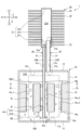
図1は、第1実施形態に係る沸騰冷却装置1の概略構成を示す斜視図である。以下の説明は、便宜上、互いに直交するX軸、Y軸およびZ軸を適宜に用いて行う。また、以下では、X軸に沿う一方向がX1方向であり、X1方向とは反対の方向がX2方向である。Y軸に沿う一方向がY1方向であり、Y1方向とは反対の方向がY2方向である。Z軸に沿う一方向がZ1方向であり、Z1方向とは反対の方向がZ2方向である。
1. First embodiment 1-1. Overview of the boiling cooling device FIG. 1 is a perspective view showing a schematic configuration of a boiling
ここで、典型的には、Z軸が鉛直線であり、Z1方向が鉛直上方に相当し、Z2方向が鉛直下方に相当する。なお、実空間でのZ軸の向きは、沸騰冷却装置1の設置姿勢に応じて決められる。Z軸は、鉛直線に対して45°以下の範囲内で傾斜してもよい。また、以下では、単に「上方」とは、鉛直線に沿う方向での位置を示しており、鉛直上方および鉛直斜め上方の双方を概念として含む。同様に、単に「下方」とは、鉛直線に沿う方向での位置を示しており、鉛直下方および鉛直斜め下方の双方を概念として含む。
Here, typically, the Z axis is a vertical line, the Z1 direction corresponds to the vertically upward direction, and the Z2 direction corresponds to the vertically downward direction. The orientation of the Z axis in real space is determined according to the installation posture of the
沸騰冷却装置1は、図1中に二点鎖線で示す2個の発熱体100を冷却する。各発熱体100は、例えば、ダイオードまたはIGBT(Insulated Gate Bipolar Transistor)等のパワー半導体素子である。パワー半導体素子は、例えば、鉄道車両、自動車または家庭用電気機械等に搭載されるインバーターまたは整流器等のパワーエレクトロニクス製品に搭載される。
The boiling
図1に示す例では、各発熱体100がXZ平面に沿う扁平形状をなす。また、2個の発熱体100は、沸騰冷却装置1を挟むように、Y軸に沿う方向に並んで配置される。なお、図1では、発熱体100の外形が概略的に示される。発熱体100の形状は、図1に示す例に限定されず、任意である。また、2個の発熱体100のうちの一方が省略されてもよい。また、発熱体100は、パワー半導体素子に限定されず、冷却を必要とするのであれば、駆動または通電等により発熱する他の電気部品または電子部品でもよい。
In the example shown in FIG. 1, each
沸騰冷却装置1は、気化した冷媒REと液化した冷媒REとの密度差を利用したループ型サーモサイフォンの冷却器である。沸騰冷却装置1は、受熱部10と放熱部20と第1管部30と第2管部40とを有する。
The boiling
受熱部10では、冷媒REが発熱体100からの熱により加熱され、冷媒REが気化されることにより、気相冷媒が生成される。当該気相冷媒は、密度の減少により第1管部30を通じて上昇し、放熱部20に輸送される。放熱部20では、当該気相冷媒が放熱により冷却され、当該気相冷媒が凝縮されることにより、液相冷媒が生成される。当該液相冷媒は、密度の増大により第2管部40を通じて下降することにより受熱部10に輸送される。このように、気化した冷媒REと液化した冷媒REとの密度差により受熱部10からの冷媒REを第1管部30、放熱部20、第2管部40および受熱部10の順に循環させながら、発熱体100の冷却が行われる。以下、沸騰冷却装置1の各部を順に説明する。
In the
1-2.沸騰冷却装置の各部
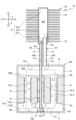
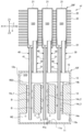
図2は、図1に示す沸騰冷却装置1の断面図である。図3は、図2中のA-A線断面図である。なお、図2では、沸騰冷却装置1をX軸およびZ軸を含む平面で切断した断面が示される。また、図3では、受熱部10をX軸およびY軸を含む平面で切断した断面が示される。
1-2. Components of the boiling cooling device Fig. 2 is a cross-sectional view of the boiling
1-2a.受熱部
受熱部10は、収容室S10を有する構造体であり、発熱体100からの熱を受ける。収容室S10は、発熱体100からの熱により気化させるための液状の冷媒REを収容する空間である。受熱部10では、発熱体100の熱によって冷媒REが気化されることにより気相冷媒が生成される。
The
冷媒REとしては、特に限定されないが、例えば、水等の水系冷媒、メタノール等のアルコール系冷媒、アセトン等のケトン系冷媒、エチレングリコール等のグリコール系冷媒、フロリナート等のフッ化炭素系冷媒、HFC134a等のフロン系冷媒、およびブタン等の炭化水素系冷媒等が挙げられる。なお、冷媒REには、必要に応じて、フッ素系界面活性剤、シリコーン系界面活性剤または炭化水素系界面活性剤等の界面活性剤等が添加されてもよい。また、冷媒REは、前述の冷媒の2種以上を組み合わせてもよい。 Refrigerant RE is not particularly limited, but examples include water-based refrigerants such as water, alcohol-based refrigerants such as methanol, ketone-based refrigerants such as acetone, glycol-based refrigerants such as ethylene glycol, fluorocarbon-based refrigerants such as Fluorinert, fluorocarbon-based refrigerants such as HFC134a, and hydrocarbon-based refrigerants such as butane. If necessary, surfactants such as fluorine-based surfactants, silicone-based surfactants, or hydrocarbon-based surfactants may be added to the refrigerant RE. The refrigerant RE may also be a combination of two or more of the above-mentioned refrigerants.
図2に示す例では、受熱部10は、収容室S10を内部空間として有する箱状をなす容器である。ここで、受熱部10は、底板11と天板12と側壁13と伝熱部材14を有する。
In the example shown in FIG. 2, the
底板11および天板12のそれぞれは、Z軸に直交する方向に広がる平板である。ただし、天板12は、底板11に対してZ1方向に位置しており、天板12には、第1管部30および第2管部40との接続のための孔が設けられる。底板11および天板12は、互いに平行となるように配置されており、これらの間には、側壁13が配置される。
The
側壁13は、底板11および天板12の外周同士を全周にわたって連結する。本実施形態では、側壁13の外周面には、発熱体100が接触する。また、側壁13の内側には、伝熱部材14が配置される。伝熱部材14は、発熱体100と受熱部10とが並ぶ方向からみて発熱体100に重なる。
The
伝熱部材14は、収容室S10を上下に二分するように配置され、側壁13に接続される熱伝導性の部材である。ここで、伝熱部材14は、Z軸に直交する面に沿って広がる板状またはブロック状をなしており、Z2方向を向く第1面14aと、Z1方向を向く第2面14bと、Z軸に沿う方向に貫通する複数の貫通孔14c_1~14c_3と、を有する。貫通孔14c_1~14c_3のそれぞれは、第1面14aおよび第2面14bのそれぞれに開口する空間である。このため、収容室S10では、伝熱部材14よりもZ1方向に位置する空間とZ2方向に位置する空間とが貫通孔14c_1~14c_3を介して連通する。なお、以下では、貫通孔14c_1~14c_3を区別しない場合、これらのそれぞれを単に貫通孔14cという場合がある。
The
本実施形態では、貫通孔14c_1~14c_3は、互いに同一形状をなす。また、貫通孔14c_1~14c_3のそれぞれの幅は、一定である。図3に示す例では、貫通孔14c_1~14c_3のそれぞれの横断面は、円形をなす。このような形状の貫通孔14c_1~14c_3は、例えば、切削等により形成される。 In this embodiment, the through holes 14c_1 to 14c_3 have the same shape. Furthermore, the width of each of the through holes 14c_1 to 14c_3 is constant. In the example shown in FIG. 3, the cross section of each of the through holes 14c_1 to 14c_3 is circular. The through holes 14c_1 to 14c_3 having such a shape are formed, for example, by cutting.
なお、貫通孔14c_1~14c_3の形状は、互いに異なってもよい。また、貫通孔14c_1~14c_3のそれぞれの幅は、一定でなくてもよい。さらに、貫通孔14c_1~14c_3のそれぞれの横断面形状は、円形に限定されず、例えば、後述の変形例3のような四角形等の多角形、楕円形等でもよい。また、伝熱部材14に設けられる貫通孔14cの数は、3個に限定されず、2個以下または4個以上でもよい。また、伝熱部材14に設けられる複数の貫通孔14cは、X軸に沿う方向に並ぶ態様に限定されず、例えば、Z軸に直交する平面に沿って、千鳥状または行列状等に規則的に配置されてもよいし、不規則に配置されてもよい。
The shapes of the through holes 14c_1 to 14c_3 may be different from each other. The widths of the through holes 14c_1 to 14c_3 may not be constant. The cross-sectional shape of each of the through holes 14c_1 to 14c_3 is not limited to a circle, and may be, for example, a polygon such as a square, as in
ここで、伝熱部材14は、冷媒REの液面RE0よりも下方に配置される。したがって、第1面14a、第2面14bおよび貫通孔14c_1~14c_3の内周面のそれぞれは、冷媒REに接触する伝熱面FHの一部を構成する。なお、伝熱面FHは、第1面14a、第2面14bおよび貫通孔14c_1~14c_3の内周面のほか、側壁13の内壁面13aの一部と底板11の内壁面11aとを含む。
Here, the
このような伝熱部材14は、冷媒REの核沸騰を促進させる機能を有する。具体的に説明すると、伝熱部材14は、底板11、天板12および側壁13のみで受熱部10を構成する場合に比べて、冷媒REと接触する伝熱面FHの面積を増大させる。したがって、伝熱面FHで生じる冷媒REの核沸騰による気泡量を増やすことができる。
Such a
しかも、貫通孔14c_1~14c_3のそれぞれの内周面には、冷媒REの核沸騰を促進させる構造が設けられる。当該構造は、例えば、伝熱面FHの表面積を増大させる構造である。図2に示す例では、貫通孔14c_1~14c_3のそれぞれの内周面には、冷媒REの核沸騰を促進させる構造として、複数の凹部または複数の凸部が設けられる。当該凹部または当該凸部は、例えば、貫通孔14c_1~14c_3の周方向に延びる溝である。当該溝は、例えば、貫通孔14c_1~14c_3を切削等の加工により形成した場合に得られる加工痕であるか、または、貫通孔の形成後のネジ切加工等の加工により得られるネジ溝である。 Moreover, a structure that promotes nucleate boiling of the refrigerant RE is provided on the inner circumferential surface of each of the through holes 14c_1 to 14c_3. The structure is, for example, a structure that increases the surface area of the heat transfer surface FH. In the example shown in FIG. 2, a plurality of recesses or protrusions are provided on the inner circumferential surface of each of the through holes 14c_1 to 14c_3 as a structure that promotes nucleate boiling of the refrigerant RE. The recesses or protrusions are, for example, grooves extending in the circumferential direction of the through holes 14c_1 to 14c_3. The grooves are, for example, processing marks obtained when the through holes 14c_1 to 14c_3 are formed by processing such as cutting, or thread grooves obtained by processing such as thread cutting after the formation of the through holes.
なお、冷媒REの核沸騰を促進させる構造としては、前述のような複数の凹部または複数の凸部のほか、例えば、ディンプル加工による複数の凹部、ブラスト処理による複数の凹凸部、エッチング処理による凹部パターンまたは凸部パターン、連続空孔を有する多孔質体の表面、押出成形、溶接またはロウ付け等により形成される並列型、格子型または波型のフィン等が挙げられる。 In addition to the multiple recesses or multiple protrusions described above, examples of structures that promote nucleate boiling of the refrigerant RE include multiple recesses formed by dimple processing, multiple uneven portions formed by blasting, a recess or protrusion pattern formed by etching, the surface of a porous body having continuous pores, and parallel, lattice, or wave-shaped fins formed by extrusion molding, welding, brazing, etc.
以上のように、受熱部10で液状の冷媒REが接触する伝熱面FHのうち、貫通孔14c_1~14c_3のそれぞれの内周面の部分は、発熱体100からの熱により冷媒REの核沸騰を生じさせやすい第1部分FH1である。
As described above, among the heat transfer surface FH with which the liquid refrigerant RE comes into contact at the
一方、伝熱面FHのうち、第1部分FH1以外の部分は、第1部分FH1よりも冷媒REの核沸騰を生じさせ難い第2部分FH2である。なお、第2部分FH2は、冷媒REの核沸騰を実質的に生じさせないか、または、冷媒REの核沸騰を生じさせても、第1部分FH1に比べて単位面積あたりで核沸騰により生じる気泡量が少ない。 On the other hand, the portion of the heat transfer surface FH other than the first portion FH1 is the second portion FH2, which is less likely to cause nucleate boiling of the refrigerant RE than the first portion FH1. The second portion FH2 does not substantially cause nucleate boiling of the refrigerant RE, or, even if nucleate boiling of the refrigerant RE occurs, the amount of bubbles caused by nucleate boiling per unit area is smaller than that of the first portion FH1.
伝熱面FHの各部位での冷媒REの核沸騰は、例えば、伝熱面FHの各部位の表面粗さ等の表面形状に影響される。一般的には、例えば、液状の冷媒に接する面において、表面粗さの異なる2つの面のうち、表面粗さの粗い面では核沸騰が起こりやすく、滑らかな面では核沸騰が起こりにくい。 Nucleate boiling of the refrigerant RE at each part of the heat transfer surface FH is affected by the surface shape, such as the surface roughness, of each part of the heat transfer surface FH. Generally, for example, on a surface that comes into contact with a liquid refrigerant, of two surfaces with different surface roughness, nucleate boiling is more likely to occur on the rougher surface, and less likely to occur on the smoother surface.
ここで、第1部分FH1の表面粗さは、第2部分FH2の表面粗さよりも大きい。第1部分FH1の具体的な表面粗さは、特に限定されないが、冷媒REの核沸騰を好適に生じさせる観点から、例えば、10μm以上10000μm以下の範囲内であることが好ましい。一方、第2部分FH2の具体的な表面粗さは、特に限定されないが、冷媒REの核沸騰を好適に抑制する観点から、後述の開口41aの近傍部分が鏡面に近いことが好ましく、例えば、1μm以下の範囲内であることが好ましい。なお、表面粗さは、算術平均粗さRaである。
Here, the surface roughness of the first portion FH1 is greater than that of the second portion FH2. The specific surface roughness of the first portion FH1 is not particularly limited, but from the viewpoint of favorably causing nucleate boiling of the refrigerant RE, it is preferable that it is, for example, in the range of 10 μm or more and 10,000 μm or less. On the other hand, the specific surface roughness of the second portion FH2 is not particularly limited, but from the viewpoint of favorably suppressing nucleate boiling of the refrigerant RE, it is preferable that the portion near the
受熱部10は、熱伝導性に優れる材料で構成される。受熱部10の具体的な構成材料としては、例えば、銅、アルミニウムまたはこれらのいずれかの合金等の金属材料が挙げられる。なお、受熱部10の底板11、天板12、側壁13および伝熱部材14の各部の構成材料は、互いに同じであっても異なってもよい。また、底板11、天板12、側壁13および伝熱部材14のそれぞれは別部材で構成されてもよいし、底板11、天板12、側壁13および伝熱部材14は、一体で構成されてもよい。
The
以上の受熱部10には、発熱体100が熱的に接続される。本実施形態では、発熱体100が側壁13の外表面に熱的に接続される。ここで、「熱的に接続」とは、次の条件a、bまたはcのいずれかを満たすことをいう。条件a:2つの部材が物理的に直接に接する。条件b:2つの部材が50μm以下の間隙を介して配置される。条件c:2つの部材が10W・m-1・K-1以上の熱伝導率の他の部材を介して物理的に接続される。なお、各条件における2つの部材間には、伝熱グリースおよび接着剤等が存在してもよい。この場合、接着剤は、熱伝導性を高める観点から、熱伝導性のフィラー等を含むことが好ましい。
The
1-2b.放熱部
放熱部20は、凝縮室S20を有する構造体であり、受熱部10からの熱を放熱する。凝縮室S20は、冷媒REを気化した状態から凝縮液化させる空間である。放熱部20では、受熱部10で生成された気相冷媒が凝縮されることにより液相冷媒が生成される。ここで、放熱部20は、凝縮室S20の気相冷媒を外部の流体との熱交換により放熱することにより凝縮液化させる。当該外部の流体は、凝縮室S20の外部を流動する流体であればよく、特に限定されず、液体でも気体でもよいが、典型的には、例えば空気である。
1-2b. Heat Dissipation Section The
図2に示す例では、放熱部20は、容器21と複数の放熱フィン22とを有する。容器21は、凝縮室S20を内部空間として有する。容器21は、底板211と天板212と側壁213とを有する。これらで囲まれた空間が凝縮室S20である。底板211および天板212のそれぞれは、Z軸に交差する方向に広がる平板である。ただし、底板211は、天板212に対してZ2方向に位置しており、底板211には、第1管部30および第2管部40との接続のための孔が設けられる。底板211および天板212は、互いに平行となるように配置されており、これらの間には、側壁213が配置される。側壁213は、底板211および天板212の外周同士を全周にわたって連結する。
2, the
本実施形態では、側壁213が円筒状をなしており、凝縮室S20が円柱状をなす。なお、凝縮室S20の形状は、円柱状に限定されず、例えば、角柱状でもよい。また、側壁213の内周面および外周面の形状は、互いに異なってもよい。
In this embodiment, the
容器21は、熱伝導性に優れる材料で構成される。容器21の具体的な材料としては、例えば、銅、アルミニウムまたはこれらのいずれかの合金等の金属材料が挙げられる。
The
各放熱フィン22は、容器21に熱的に接続される。各放熱フィン22は、平板状の部材である。複数の放熱フィン22は、互いに厚さ方向に間隔を隔てて配置される。各放熱フィン22は、熱伝導性に優れる材料で構成される。放熱フィン22の具体的な材料としては、例えば、銅、アルミニウムまたはこれらのいずれかの合金等の金属材料が挙げられる。各放熱フィン22には、容器21を挿入するための孔が設けられる。放熱フィン22は、例えば、容器21に対して拡管、圧入、接着剤、ネジ止め、ロウ付けまたは溶接等により固定される。
Each
なお、放熱フィン22の形状は、図2に示す例に限定されず、任意である。また、放熱フィン22は、必要に応じて設ければよく、省略してもよい。ただし、放熱部20が複数の放熱フィン22を有することにより、気相冷媒を効率的に凝縮液化させることができる。
The shape of the
1-2c.第1管部
第1管部30は、受熱部10で冷媒REが気化されることにより生成された気相冷媒を放熱部20に輸送する第1流路S30を有する。本実施形態では、第1管部30は、Z軸に沿って直線状に延びる蒸気管31で構成される。蒸気管31は、第1流路S30を内部空間として有する管である。
1-2c. First pipe section The
蒸気管31は、例えば、銅、アルミニウムまたはこれらのいずれかの合金等の金属材料で構成される。また、蒸気管31は、天板12および底板211に対してロウ付け等により固定される。なお、蒸気管31の構成材料は、金属材料に限定されず、例えば、セラミックス材料または樹脂材料等でもよい。
The
第1管部30は、受熱部10および放熱部20のそれぞれに接続されており、受熱部10に向けて開口する開口31aと、放熱部20に向けて開口する開口31bと、を有する。開口31aは、第1管部30の内周面31cのZ2方向での端縁で囲まれる空間である。開口31bは、第1管部30の内周面31cのZ1方向での端縁で囲まれる空間である。
The
ここで、開口31aは、天板12のZ2方向を向く面である内壁面12aと同一平面上に位置する。また、第1管部30の一部は、放熱部20の底板211よりもZ1方向に突出する。したがって、開口31bは、底板211よりもZ1方向に位置する。なお、第1流路S30は、蒸気管31と前述の受熱部10の天板12とにより形成されてもよい。この場合、開口31aは、天板12に設けられる孔により形成される。
Here, the
第1流路S30は、第1管部30の内周面31cで囲まれる空間である。第1流路S30は、開口31aを介して収容室S10に連通するとともに、開口31bを介して凝縮室S20に連通する。
The first flow path S30 is a space surrounded by the inner
図2に示す例では、第1流路S30の幅は、一定である。また、第1流路S30の断面積は、一定である。さらに、第1流路S30の横断面の形状は、円形である。なお、第1流路S30の横断面の形状は、円形に限定されず、例えば、四角形等の多角形、楕円形等でもよい。また、第1流路S30は、屈曲または湾曲する部分を有してもよい。 In the example shown in FIG. 2, the width of the first flow path S30 is constant. Also, the cross-sectional area of the first flow path S30 is constant. Furthermore, the cross-sectional shape of the first flow path S30 is circular. Note that the cross-sectional shape of the first flow path S30 is not limited to a circle, and may be, for example, a polygon such as a square, an ellipse, or the like. Also, the first flow path S30 may have a bent or curved portion.
1-2d.第2管部
第2管部40は、放熱部20で気相冷媒が凝縮されることにより生成された液相冷媒を受熱部10に輸送する第2流路S40を有する。本実施形態では、第2管部40は、Z軸に沿って直線状に延びる液管41で構成される。液管41は、第2流路S40を内部空間として有する管である。
1-2d. Second pipe section The
液管41は、例えば、銅、アルミニウムまたはこれらのいずれかの合金等の金属材料で構成される。また、液管41は、天板12および底板211に対してロウ付け等により固定される。なお、液管41の構成材料は、金属材料に限定されず、例えば、セラミックス材料または樹脂材料等でもよい。また、液管41の構成材料は、蒸気管31の構成材料と同一であってもよいし異なってもよい。
The
第2管部40は、受熱部10および放熱部20のそれぞれに接続されており、受熱部10に向けて開口する「第1開口」の一例である開口41aと、放熱部20に向けて開口する「第2開口」の一例である開口41bと、を有する。開口41aは、第2管部40の内周面41cのZ2方向での端縁で囲まれる空間である。開口41bは、第2管部40の内周面41cのZ1方向での端縁で囲まれる空間である。
The
ここで、第2管部40の一部は、受熱部10の天板12よりもZ2方向に突出する。本実施形態では、第2管部40は、前述の伝熱部材14の貫通孔14cに挿入されており、開口41aは、伝熱部材14よりもZ2方向に位置する。したがって、開口41aは、伝熱部材14と底板11との間に位置する。また、開口41bは、放熱部20の底板211のZ1方向を向く面と同一平面上に位置する。なお、第2流路S40は、液管41と前述の放熱部20の底板211とにより形成されてもよい。この場合、開口41bは、底板211に設けられる孔により形成される。
Here, a part of the
第2流路S40は、第2管部40の内周面41cで囲まれる空間である。第2流路S40は、開口41aを介して収容室S10に連通するとともに、開口41bを介して凝縮室S20に連通する。
The second flow path S40 is a space surrounded by the inner
第2流路S40の断面積は、前述の第1流路S30の断面積よりも小さい。すなわち、第1流路S30の断面積は、第2流路S40の断面積よりも大きい。このため、第1流路S30の断面積が第2流路S40の断面積以下である構成に比べて、第1流路S30での気相冷媒の輸送を円滑に行うことができる。なお、第2流路S40の断面積は、第1流路S30の断面積に等しくてもよい。 The cross-sectional area of the second flow path S40 is smaller than the cross-sectional area of the first flow path S30 described above. That is, the cross-sectional area of the first flow path S30 is larger than the cross-sectional area of the second flow path S40. Therefore, the transport of the gas phase refrigerant in the first flow path S30 can be performed more smoothly than in a configuration in which the cross-sectional area of the first flow path S30 is equal to or smaller than the cross-sectional area of the second flow path S40. Note that the cross-sectional area of the second flow path S40 may be equal to the cross-sectional area of the first flow path S30.
図2に示す例では、第2流路S40の幅は、一定である。また、第2流路S40の断面積は、一定である。さらに、第2流路S40の横断面の形状は、円形である。なお、第2流路S40の横断面の形状は、円形に限定されず、例えば、四角形等の多角形、楕円形等でもよい。また、第2流路S40は、屈曲または湾曲する部分を有してもよい。 In the example shown in FIG. 2, the width of the second flow path S40 is constant. The cross-sectional area of the second flow path S40 is also constant. The cross-sectional shape of the second flow path S40 is circular. Note that the cross-sectional shape of the second flow path S40 is not limited to a circle, and may be, for example, a polygon such as a square, an ellipse, or the like. The second flow path S40 may also have a bent or curved portion.
以上の第2管部40では、前述のように、開口41aは、伝熱部材14と底板11との間に位置する。ここで、前述のように、伝熱部材14の貫通孔14cの内周面は、冷媒REの核沸騰を生じさせる第1部分FH1であるのに対し、底板11の内壁面11aは、第1部分FH1よりも冷媒REの核沸騰を生じさせ難い第2部分FH2である。そして、開口41aと第2部分FH2との間の距離L2は、開口41aと第1部分FH1との間の距離L1よりも短い。このため、第1部分FH1での冷媒REの核沸騰により生じた気泡Bが開口41aに混入し難い。
In the
距離L1は、開口41aから液状の冷媒REを通って第1部分FH1に至る最短距離である。距離L1は、距離L2よりも長ければよいが、図2に示す例では、液管41のZ2方向での端面が底板11の内壁面11aに平行であるため、当該端面と内壁面11aとが間隔を隔てるよう、開口41aからの液相冷媒の流出を妨げない範囲に設定される。なお、当該端面が内壁面11aに対して傾斜したり当該端面に切り欠き等を設けたりしてもよい。この場合、当該端面と内壁面11aとが接触してもよい。すなわち、この場合、距離L2がゼロでもよい。
The distance L1 is the shortest distance from the
距離L2は、開口41aから液状の冷媒REを通って第2部分FH2に至る最短距離である。距離L2は、距離L1よりも短ければよいが、本実施形態のように開口41aが第1部分FH1よりも下方に位置する場合、受熱部10に要求される形状、必要な大きさにより適宜決定できるが、1mm以上であることが好ましい。この場合、第1部分FH1から開口41aへの気泡Bの混入を好適に低減することができる。
The distance L2 is the shortest distance from the
1-3.まとめ
以上の沸騰冷却装置1は、前述のように、受熱部10と放熱部20と第1管部30と第2管部40とを備える。受熱部10は、冷媒REを収容し、発熱体100からの熱を受ける。放熱部20は、受熱部10からの熱を放熱する。第1管部30は、受熱部10で冷媒REが気化されることにより生成された気相冷媒を放熱部20に輸送する。第2管部40は、放熱部20で気相冷媒が凝縮されることにより生成された液相冷媒を受熱部10に輸送する。
1-3. Summary As described above, the boiling
ここで、受熱部10は、発熱体100からの熱により気化させるための液状の冷媒REに接触する伝熱面FHを有する。伝熱面FHは、冷媒REの核沸騰を生じさせる第1部分FH1と、第1部分FH1よりも冷媒REの核沸騰を生じさせ難い第2部分FH2と、を有する。第2管部40は、受熱部10に向けて開口する「第1開口」の一例である開口41aと、放熱部20に向けて開口する「第2開口」の一例である開口41bと、を有する。
Here, the
そのうえで、開口41aは、受熱部10に収容される冷媒REの液面RE0よりも下方に位置する。そして、開口41aと第2部分FH2との間の距離L2は、開口41aと第1部分FH1との間の距離L1よりも短い。
The
以上の沸騰冷却装置1では、開口41aが受熱部10での冷媒REの液面RE0によりも下方に位置するので、受熱部10で生成した気相冷媒が開口41aに流入することを防止することができる。このため、受熱部10からの気相冷媒を第1管部30に流入させやすくすることができる。
In the boiling
しかも、開口41aと第2部分FH2との間の距離L2が開口41aと第1部分FH1との間の距離L1よりも短いので、第1部分FH1での冷媒REの核沸騰により生じた気泡Bが開口41aに混入することを防止することもできる。このため、第2管部40から受熱部10への液相冷媒の流入が気泡Bにより阻害されることを低減することができる。この結果、受熱部10から第1管部30、放熱部および第2管部40をこの順に通って受熱部10に戻るという冷媒REの循環が従来に比べて円滑に行われるので、冷却性能の低下を低減することができる。
In addition, since the distance L2 between the
前述のように、鉛直方向にみて開口41aに重なる領域において、開口41aよりも下方には、第1部分FH1が存在しない。第1部分FH1での核沸騰により生じた気泡Bは、その浮力により受熱部10での冷媒REの液面RE0に向けて鉛直上方に移動する。したがって、開口41aへの当該気泡Bの混入を低減する観点から、鉛直方向にみて開口41aに重なる領域において、開口41aよりも下方には、第1部分FH1が存在しないことが好ましい。
As described above, in the region overlapping with the
また、前述のように、開口41aおよび第2部分FH2のそれぞれは、第1部分FH1よりも下方に位置する。このため、距離L2を距離L1よりも短くすることができる。また、受熱部10での冷媒REが流動しても、第1部分FH1での核沸騰により生じた気泡Bが開口41aに混入することを低減することができる。
As described above, the
さらに、前述のように、第1部分FH1は、鉛直線に沿って延びる。このため、第1部分FH1での冷媒REの核沸騰により生じた気泡Bが伝熱面FHから離脱しやすい。この結果、伝熱面FHでの当該気泡Bの滞留が低減されるので、冷却性能の低下を低減することができる。また、受熱部10および発熱体100が水平方向に沿って並んで配置される場合、発熱体100からの熱が第1部分FH1に伝わりやすいので、第1部分FH1での冷媒REの核沸騰を効率的に生じさせることができる。なお、「鉛直線に沿って延びる」とは、鉛直線に一致する方向に延びることと、鉛直線に対して45°以下で傾斜した方向で延びることと、の双方を概念として含む。
Furthermore, as described above, the first portion FH1 extends along a vertical line. Therefore, bubbles B generated by nucleate boiling of the refrigerant RE in the first portion FH1 are easily separated from the heat transfer surface FH. As a result, the retention of the bubbles B on the heat transfer surface FH is reduced, so that the deterioration of cooling performance can be reduced. In addition, when the
本実施形態では、前述のように、受熱部10は、鉛直線に沿って延びる貫通孔14cを有する伝熱部材14を有する。そして、貫通孔14cの内周面の少なくとも一部は、第1部分FH1である。そのうえで、第2管部40は、貫通孔14cに挿入される。貫通孔14cを有する伝熱部材14を用いることにより、受熱部10における伝熱面FHの面積を大きくしやすいという利点がある。また、第1管部30の貫通孔14cに第1管部30を挿入することにより、開口41aを第1部分FH1よりも下方に配置することができる。
In this embodiment, as described above, the
また、前述のように、開口41aは、貫通孔14cよりも下方に位置する。このため、貫通孔14cの内壁面の全域に第1部分FH1を設けても、開口41aを第1部分FH1よりも下方に配置することができる。
As described above, the
さらに、前述のように、開口41aは、下方を向く。このため、開口41aが鉛直上方または水平方向を向く構成に比べて、第2管部40の製造または組み立てが簡単に済むという利点がある。その半面、開口41aが下方を向く場合、開口41aが鉛直上方または水平方向を向く場合に比べて、仮に開口41aの近傍で核沸騰により気泡Bが生じると、その気泡Bが開口41aに混入しやすい。したがって、この場合、前述のように開口41aと第2部分FH2との間の距離L2を開口41aと第1部分FH1との間の距離L1よりも短くすることは、開口41aへの当該気泡Bの混入を低減するうえで、有用である。
Furthermore, as described above, the
また、前述のように、第1部分FH1の表面粗さは、第2部分FH2の表面粗さよりも大きい。このため、第1部分FH1で冷媒REの核沸騰を効率的に生じさせることができる。 As described above, the surface roughness of the first portion FH1 is greater than the surface roughness of the second portion FH2. This allows nucleate boiling of the refrigerant RE to occur efficiently in the first portion FH1.
2.第2実施形態
以下、本発明の第2実施形態について説明する。以下に例示する形態において作用や機能が前述の実施形態と同様である要素については、前述の実施形態の説明で使用した符号を流用して各々の詳細な説明を適宜に省略する。
2. Second embodiment Hereinafter, a second embodiment of the present invention will be described. In the following exemplary embodiment, for elements whose actions and functions are similar to those of the above-mentioned embodiment, the reference numerals used in the description of the above-mentioned embodiment will be used, and detailed descriptions of each will be omitted as appropriate.
図4は、第2実施形態に係る沸騰冷却装置1Aの断面図である。沸騰冷却装置1Aは、受熱部10に代えて受熱部10Aを有する以外は、前述の第1実施形態の沸騰冷却装置1と同様である。受熱部10Aは、抑制部15を追加した以外は、受熱部10と同様である。
Figure 4 is a cross-sectional view of the boiling
抑制部15は、開口41aへの気泡Bの混入を低減するよう、冷媒REの核沸騰を抑制する機能を有する。抑制部15は、例えば、超撥水コーティング膜または鏡面で構成される。抑制部15は、第2部分FH2に設けられる。より具体的には、抑制部15は、開口41aの鉛直下方に位置するよう、底板11の内壁面11aに配置される。
The
以上の第2実施形態によっても、前述の第1実施形態と同様、冷却性能の低下を低減することができる。本実施形態では、前述のように、第2部分FH2には、鉛直方向にみて開口41aに重なる領域に、冷媒REの核沸騰を抑制する抑制部15が設けられる。このため、開口41aの下方での気泡Bの存在率を低下させることができる。この結果、開口41aへの気泡Bの混入が好適に防止される。
The second embodiment described above can also reduce the deterioration of cooling performance, as in the first embodiment described above. In this embodiment, as described above, the second portion FH2 is provided with a
3.第3実施形態
以下、本発明の第3実施形態について説明する。以下に例示する形態において作用や機能が前述の実施形態と同様である要素については、前述の実施形態の説明で使用した符号を流用して各々の詳細な説明を適宜に省略する。
3. Third embodiment Hereinafter, a third embodiment of the present invention will be described. In the following exemplary embodiment, for elements whose actions and functions are similar to those of the above-mentioned embodiment, the reference numerals used in the description of the above-mentioned embodiment will be used, and detailed descriptions of each will be omitted as appropriate.
図5は、第3実施形態に係る沸騰冷却装置1Bの断面図である。沸騰冷却装置1Bは、受熱部10および第2管部40に代えて受熱部10Bおよび第2管部40Bを有する以外は、前述の第1実施形態の沸騰冷却装置1と同様である。受熱部10Bは、抑制部16を追加した以外は、受熱部10と同様である。また、第2管部40Bは、液管41に代えて液管41Bを有する以外は、第2管部40と同様である。
Figure 5 is a cross-sectional view of the boiling
抑制部16は、前述の第2実施形態の抑制部15と同様、例えば、超撥水コーティング膜または鏡面で構成される。抑制部16は、伝熱部材14の第1面14aからZ1方向に延びるよう、伝熱部材14の貫通孔14c_2の内周面の一部に設けられる。このため、貫通孔14c_2の内周面のうち、抑制部16が設けられない部分は、第1部分FH1であり、抑制部16が設けられる部分は、第2部分FH2である。
Similar to the
液管41Bは、天板12からの突出長さが異なる以外は、第1実施形態の液管41と同様である。液管41Bの開口41aは、貫通孔14c_2内に位置する。より具体的には、開口41aは、Z軸に直交する方向にみて、抑制部16に重なる位置に配置される。
The
以上の第3実施形態によっても、前述の第1実施形態と同様、冷却性能の低下を低減することができる。本実施形態では、前述のように、貫通孔14c_2の内周面の一部は、第2部分FH2である。そして、開口41aは、貫通孔14c_2内に位置する。このように、貫通孔14c_2の内周面に第2部分FH2を設けることにより、開口41aを貫通孔14c_2内に位置しても、第1部分FH1での核沸騰により生じた気泡Bが開口41aに混入することを低減することができる。
The above third embodiment can also reduce the deterioration of cooling performance, as in the first embodiment described above. In this embodiment, as described above, a part of the inner circumferential surface of the through hole 14c_2 is the second portion FH2. And the
4.第4実施形態
以下、本発明の第4実施形態について説明する。以下に例示する形態において作用や機能が前述の実施形態と同様である要素については、前述の実施形態の説明で使用した符号を流用して各々の詳細な説明を適宜に省略する。
4. Fourth embodiment Hereinafter, a fourth embodiment of the present invention will be described. In the following exemplary embodiment, for elements whose actions and functions are similar to those of the above-mentioned embodiment, the reference numerals used in the description of the above-mentioned embodiment will be used, and detailed descriptions of each will be omitted as appropriate.
図6は、第4実施形態に係る沸騰冷却装置1Cの断面図である。沸騰冷却装置1Cは、受熱部10に代えて受熱部10Cを有する以外は、前述の第1実施形態の沸騰冷却装置1と同様である。受熱部10Cは、伝熱部材14を省略するとともに抑制部15および促進部17を追加した以外は、受熱部10と同様である。
Figure 6 is a cross-sectional view of the boiling
本実施形態では、発熱体100が底板11の外表面に熱的に接続される。また、促進部17は、冷媒REの核沸騰を促進させる構造であり、抑制部15の周囲を囲むように、底板11の内壁面11aに設けられる。
In this embodiment, the
図6に示す例では、促進部17は、複数のフィン17aを有する。当該複数のフィン17aは、例えば、並列型、格子型または波型の突起であり、押出成形、溶接またはロウ付け等により形成される。なお、促進部17は、図6に示す例に限定されず、例えば、ディンプル加工による複数の凹部、ブラスト処理による複数の凹凸部、エッチング処理による凹部パターンまたは凸部パターン、連続空孔を有する多孔質体の表面等でもよい。
In the example shown in FIG. 6, the
以上の構成では、抑制部15は、Z軸方向にみて発熱体100に重なるが、内壁面11aでの冷媒REの核沸騰が抑制部15の設けられる範囲において抑制される。一方、内壁面11aでの冷媒REの核沸騰が促進部17の設けられる範囲において促進される。このようなことから、内壁面11aのうち、促進部17が設けられる部分は、第1部分FH1であり、抑制部15が設けられる部分は、第2部分FH2である。ここで、開口41aと第2部分FH2との間の距離L2は、開口41aと第1部分FH1との間の距離L1よりも短い。
In the above configuration, the
以上の第4実施形態によっても、前述の第1実施形態と同様、冷却性能の低下を低減することができる。本実施形態では、前述のように、第1部分FH1および第2部分FH2のそれぞれは、開口41aよりも下方に位置する。第1部分FH1は、鉛直方向にみて開口41aに重ならない。一方、第2部分FH2は、鉛直方向にみて開口41aに重なる。本実施形態のように、受熱部10Cに対して下方に発熱体100が配置される場合、発熱体100からの熱が底板11の内壁面11aに伝わりやすいので、内壁面11aに第1部分FH1を設けることにより、第1部分FH1での冷媒REの核沸騰を効率的に生じさせることができる。ここで、鉛直方向にみて開口41aには、第2部分FH2が重なる一方、第1部分FH1が重ならないので、気泡Bが開口41aに混入することを低減することができる。
The fourth embodiment described above can reduce the deterioration of cooling performance, as in the first embodiment described above. In this embodiment, as described above, each of the first portion FH1 and the second portion FH2 is located below the
5.第5実施形態
以下、本発明の第5実施形態について説明する。以下に例示する形態において作用や機能が前述の実施形態と同様である要素については、前述の実施形態の説明で使用した符号を流用して各々の詳細な説明を適宜に省略する。
5. Fifth embodiment Hereinafter, a fifth embodiment of the present invention will be described. In the following exemplary embodiment, for elements whose actions and functions are similar to those of the above-mentioned embodiment, the reference numerals used in the description of the above-mentioned embodiment will be used, and detailed descriptions of each will be omitted as appropriate.
図7は、第5実施形態に係る沸騰冷却装置1Dの断面図である。沸騰冷却装置1Dは、受熱部10および第2管部40に代えて受熱部10Dおよび第2管部40Dを有する以外は、前述の第1実施形態の沸騰冷却装置1と同様である。受熱部10Dは、伝熱部材14を省略するとともに促進部18を追加した以外は、受熱部10と同様である。ただし、受熱部10Dと第2管部40Dとの接続位置は、受熱部10と第2管部40との接続位置と異なる。第2管部40Dは、液管41に代えて液管41Dを有する以外は、第2管部40Dと同様である。
Figure 7 is a cross-sectional view of the boiling
本実施形態では、前述の第5実施形態と同様、発熱体100が底板11の外表面に熱的に接続される。また、促進部18は、冷媒REの核沸騰を促進させる構造であり、底板11の内壁面11aと側壁13の内壁面13aとにそれぞれ設けられる。
In this embodiment, similar to the fifth embodiment described above, the
ここで、促進部18は、Z軸方向にみて発熱体100に重なるよう、内壁面11aのうち内壁面13aから所定距離以上離れた範囲にわたり設けられる。また、促進部18は、内壁面13aのうち内壁面11aから所定距離以上離れた範囲にわたり設けられる。
The
図7に示す例では、促進部18は、内壁面11aに設けられる複数のフィン18aと、内壁面13aに設けられる複数のフィン18bと、を有する。当該複数のフィン18aと当該複数のフィン18bとのそれぞれは、例えば、並列型、格子型または波型の突起であり、押出成形、溶接またはロウ付け等により形成される。なお、促進部18は、図7に示す例に限定されず、例えば、ディンプル加工による複数の凹部、ブラスト処理による複数の凹凸部、エッチング処理による凹部パターンまたは凸部パターン、連続空孔を有する多孔質体の表面等でもよい。
In the example shown in FIG. 7, the
以上の構成では、内壁面11aおよび内壁面13aのうち、促進部18が設けられる部分は、第1部分FH1であり、促進部18が設けられない部分は、第2部分FH2である。ここで、内壁面11aのうち促進部18が設けられない部分では、Z軸方向にみて発熱体100に重ならない部分を有しており、当該部分では、Z軸方向にみて発熱体100に重なる部分に比べて冷媒REの核沸騰が抑制される。なお、当該部分には、前述の実施形態の抑制部15または抑制部16のような構造を設けてもよい。
In the above configuration, the portion of the
液管41Dは、側壁13に接続されるとともに開口41aが水平方向を向く以外は、液管41と同様である。液管41Dは、屈曲または湾曲する部分を有しており、前述の複数のフィン18bよりも下方の位置で、側壁13に接続される。また、開口41aは、側壁13の内壁面13aから離れた位置に配置される。なお、開口41aが内壁面13aと同一平面上に配置されてもよい。
The
ここで、開口41aと第2部分FH2との間の距離L2aまたは距離L2bは、開口41aと第1部分FH1との間の距離L1aまたは距離L1bよりも短い。なお、距離L1aは、開口41aと複数のフィン18aとの間の距離である。距離L1bは、開口41aと複数のフィン18bとの間の距離である。距離L2aは、開口41aと内壁面11aとの間の距離である。距離L2bは、開口41aと内壁面13aとの間の距離である。
Here, the distance L2a or distance L2b between the
以上の第5実施形態によっても、前述の第1実施形態と同様、冷却性能の低下を低減することができる。本実施形態では、開口41aは、水平方向を向く。このため、開口41aが下方を向く構成に比べて、気泡Bが開口41aに混入し難くすることができる。
As with the first embodiment described above, the fifth embodiment can also reduce the deterioration of cooling performance. In this embodiment, the
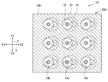
6.応用例
図8は、沸騰冷却装置1の応用例を示す斜視図である。図8では、複数の沸騰冷却装置1により複数の発熱体100を冷却する場合の例が示される。
6. Application Example Fig. 8 is a perspective view showing an application example of the
図8に示す例では、複数の沸騰冷却装置1と複数の発熱体100とがY軸に沿う方向に交互に配置される。ここで、複数の沸騰冷却装置1および複数の発熱体100は、図示しない固定具により、互いに隣り合う沸騰冷却装置1と発熱体100とが密着するよう固定される。以上の構成により、複数の沸騰冷却装置1により複数の発熱体100を冷却することができる。
In the example shown in FIG. 8, multiple boiling
なお、互いに隣り合う2つの沸騰冷却装置1の放熱フィン22が一体で構成されてもよい。また、沸騰冷却装置1の数は、冷却すべき発熱体100の数に応じて決められ、図8に示す例に限定されず、5個以下または7個以上でもよい。また、図8に示す例は、沸騰冷却装置1を用いるが、複数の沸騰冷却装置1のうちの少なくとも1つに代えて、前述の沸騰冷却装置1A、1B、1C、1Dのうちのいずれかを用いてもよいし、沸騰冷却装置1、1A、1B、1C、1Dを適宜に組み合わせてもよい。
The
7.変形例
本発明は前述の各実施形態に限定されるものではなく、以下に述べる各種の変形が可能である。また、各実施形態及び各変形例を適宜組み合わせてもよい。
The present invention is not limited to the above-described embodiments, and various modifications are possible. Furthermore, the embodiments and modifications may be combined as appropriate.
7-1.変形例1
前述の第1実施形態から第3実施形態では、複数の貫通孔14cのすべてに核沸騰を促進する構造が設けられるが、当該構造が設けられない貫通孔14cが存在してもよい。
7-1.
In the above-described first to third embodiments, the structure for promoting nucleate boiling is provided in all of the plurality of through
図9は、変形例1に係る沸騰冷却装置1Eの断面図である。沸騰冷却装置1Eは、受熱部10および第2管部40に代えて受熱部10Eおよび第2管部40Eを有する以外は、前述の第1実施形態の沸騰冷却装置1と同様である。受熱部10Eは、貫通孔14c_2について核沸騰を促進する構造を省略した以外は、受熱部10と同様である。また、第2管部40Eは、液管41に代えて液管41Eを有する以外は、第2管部40と同様である。
Figure 9 is a cross-sectional view of the boiling
図9に示す例では、貫通孔14c_1~14c_3のうち、貫通孔14c_1、14c_3の内周面は、第1部分FH1であり、貫通孔14c_2の内周面は、第2部分FH2である。 In the example shown in FIG. 9, among the through holes 14c_1 to 14c_3, the inner circumferential surface of the through holes 14c_1 and 14c_3 is the first portion FH1, and the inner circumferential surface of the through hole 14c_2 is the second portion FH2.
液管41Eは、天板12からの突出長さが異なる以外は、第1実施形態の液管41と同様である。液管41Eの開口41aは、貫通孔14c_2内に位置する。以上の変形例1によっても、前述の第1実施形態と同様、冷却性能の低下を低減することができる。
The
7-2.変形例2
前述の第1実施形態から第5実施形態では、受熱部10ごとに1つずつ放熱部20、第1管部30および第2管部40のそれぞれが設けられるが、1つの受熱部10に対して、放熱部20、第1管部30および第2管部40のそれぞれが複数設けられてもよい。ただし、複数の放熱部20の放熱フィン22は、一体で構成されてもよい。
7-2.
In the above-described first to fifth embodiments, one
図10は、変形例2に係る沸騰冷却装置1Fの断面図である。沸騰冷却装置1Fは、受熱部10および放熱部20に代えて受熱部10Fおよび放熱部20Fを有するともに、第1管部30および第2管部40のそれぞれの数が3つである以外は、前述の第1実施形態の沸騰冷却装置1と同様である。
Figure 10 is a cross-sectional view of the boiling
受熱部10Fは、3つの第1管部30よび3つの第2管部40に接続される以外は、受熱部10と同様である。放熱部20Fは、容器21の数が3つである以外は、放熱部20と同様である。ここで、3つの第2管部40のそれぞれは、貫通孔14cに個別に挿入される。以上の変形例2によっても、前述の第1実施形態と同様、冷却性能の低下を低減することができる。
The
7-3.変形例3
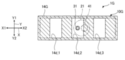
図11は、変形例3に係る沸騰冷却装置1Gの断面図である。図11では、沸騰冷却装置1Gについて図3に対応する断面が示される。沸騰冷却装置1Gは、受熱部10に代えて受熱部10Gを有する以外は、前述の第1実施形態の沸騰冷却装置1と同様である。受熱部10Gは、伝熱部材14に代えて伝熱部材14Gを有する以外は、受熱部10と同様である。伝熱部材14Gは、貫通孔14c_1~14c_3に代えて貫通孔14d_1~14d_3を有する以外は、伝熱部材14と同様である。貫通孔14d_1~14d_3のそれぞれの横断面は、四角形をなす。以上の変形例3によっても、前述の第1実施形態と同様、冷却性能の低下を低減することができる。
7-3.
FIG. 11 is a cross-sectional view of the boiling
7-4.変形例4
図12は、変形例4に係る沸騰冷却装置1Hの断面図である。図12では、沸騰冷却装置1Hについて図3に対応する断面が示される。沸騰冷却装置1Hは、受熱部10に代えて受熱部10Hを有するとともに、放熱部20、第1管部30および第2管部40のそれぞれの数が異なる以外は、前述の第1実施形態の沸騰冷却装置1と同様である。受熱部10Hは、伝熱部材14に代えて伝熱部材14Hを有する以外は、受熱部10と同様である。伝熱部材14Hは、貫通孔14cの数が異なる以外は、伝熱部材14と同様である。図12に示す例では、貫通孔14cの数が9つであり、9つの貫通孔14cが行列状に配置される。また、図12に示す例では、貫通孔14cごとに、放熱部20、第1管部30および第2管部40のそれぞれが設けられる。ただし、複数の放熱部20の放熱フィン22は、一体で構成されてもよい。以上の変形例4によっても、前述の第1実施形態と同様、冷却性能の低下を低減することができる。
7-4. Modification 4
FIG. 12 is a cross-sectional view of the boiling
1…沸騰冷却装置、1A…沸騰冷却装置、1B…沸騰冷却装置、1C…沸騰冷却装置、1D…沸騰冷却装置、1E…沸騰冷却装置、1F…沸騰冷却装置、1G…沸騰冷却装置、1H…沸騰冷却装置、10…受熱部、10A…受熱部、10B…受熱部、10C…受熱部、10D…受熱部、10E…受熱部、10F…受熱部、10G…受熱部、10H…受熱部、11…底板、11a…内壁面、12…天板、12a…内壁面、13…側壁、13a…内壁面、14…伝熱部材、14G…伝熱部材、14H…伝熱部材、14a…第1面、14b…第2面、14c…貫通孔、14c_1…貫通孔、14c_2…貫通孔、14c_3…貫通孔、14d_1…貫通孔、15…抑制部、16…抑制部、17…促進部、17a…フィン、18…促進部、18a…フィン、18b…フィン、20…放熱部、20F…放熱部、21…容器、22…放熱フィン、30…第1管部、31…蒸気管、31a…開口、31b…開口、31c…内周面、40…第2管部、40B…第2管部、40D…第2管部、40E…第2管部、41…液管、41B…液管、41D…液管、41E…液管、41a…開口(第1開口)、41b…開口(第2開口)、41c…内周面、100…発熱体、211…底板、212…天板、213…側壁、B…気泡、FH…伝熱面、FH1…第1部分、FH2…第2部分、L1…距離、L1a…距離、L1b…距離、L2…距離、L2a…距離、L2b…距離、RE…冷媒、RE0…液面、S10…収容室、S20…凝縮室、S30…第1流路、S40…第2流路。 1... Boiling cooling device, 1A... Boiling cooling device, 1B... Boiling cooling device, 1C... Boiling cooling device, 1D... Boiling cooling device, 1E... Boiling cooling device, 1F... Boiling cooling device, 1G... Boiling cooling device, 1H ... Boiling cooling device, 10... Heat receiving part, 10A... Heat receiving part, 10B... Heat receiving part, 10C... Heat receiving part, 10D... Heat receiving part, 10E... Heat receiving part, 10F... Heat receiving part, 10G... Heat receiving part, 10H... Heat receiving part, 11... Bottom plate, 11a...inner wall surface, 12...top plate, 12a...inner wall surface, 13...side wall, 13a...inner wall surface, 14...heat transfer member, 14G...heat transfer member, 14H...heat transfer member, 14a...first surface, 14b...second surface, 14c...through hole, 14c_1...through hole, 14c_2...through hole, 14c_3...through hole, 14d_1...through hole, 15...suppression portion, 16...suppression portion, 17...promotion portion, 17a...fin, 18...promotion portion, 18a...fins, 18b...fins, 20...heat dissipation portion, 20F...heat dissipation portion, 21...container, 22...heat dissipation fins, 30...first pipe portion, 31...steam pipe, 31a...opening, 31b...opening, 31c...inner circumferential surface, 40...second pipe portion, 40B...second pipe portion, 40D...second pipe portion, 40E...second pipe portion, 41...liquid pipe, 41B...liquid pipe, 41D...liquid pipe, 41E...liquid pipe, 41a...opening (first opening), 41b ...opening (second opening), 41c...inner surface, 100...heat generating element, 211...bottom plate, 212...top plate, 213...side wall, B...air bubble, FH...heat transfer surface, FH1...first part, FH2...second part, L1...distance, L1a...distance, L1b...distance, L2...distance, L2a...distance, L2b...distance, RE...refrigerant, RE0...liquid level, S10...storage chamber, S20...condensation chamber, S30...first flow path, S40...second flow path.
Claims (10)
前記受熱部からの熱を放熱する放熱部と、
前記受熱部で冷媒が気化されることにより生成された気相冷媒を前記放熱部に輸送する第1管部と、
前記放熱部で前記気相冷媒が凝縮されることにより生成された液相冷媒を前記受熱部に輸送する第2管部と、を備え、
前記受熱部は、発熱体からの熱により気化させるための液状の冷媒に接触する伝熱面を有し、
前記伝熱面は、冷媒の核沸騰を生じさせる第1部分と、前記第1部分よりも冷媒の核沸騰を生じさせ難い第2部分と、を有し、
前記受熱部は、鉛直線に沿って延びる貫通孔を有する伝熱部材を有し、
前記貫通孔の内周面の少なくとも一部は、前記第1部分であり、
前記第2管部は、前記貫通孔に挿入されており、
前記第1部分は、鉛直線に沿って並ぶ複数の凹部または複数の凸部で構成され、
前記第2管部は、前記受熱部に向けて開口する第1開口と、前記放熱部に向けて開口する第2開口と、を有し、
前記第1開口は、前記受熱部に収容される冷媒の液面よりも下方に位置し、
前記第1開口および前記第2部分のそれぞれは、前記第1部分の下端よりも下方に位置し、
前記第1開口から液状の冷媒を通って前記第1部分に至る最短距離は、前記第1開口から液状の冷媒を通って前記第2部分に至る最短距離よりも長い、
沸騰冷却装置。 a heat receiving portion that accommodates a refrigerant and receives heat from a heating element;
A heat dissipation section that dissipates heat from the heat receiving section;
A first pipe portion that transports a gas phase refrigerant generated by vaporizing the refrigerant in the heat receiving portion to the heat dissipating portion;
a second pipe portion that transports a liquid-phase refrigerant generated by condensing the gas-phase refrigerant in the heat dissipation portion to the heat receiving portion,
The heat receiving portion has a heat transfer surface that contacts a liquid refrigerant to be vaporized by heat from a heating element,
The heat transfer surface has a first portion that causes nucleate boiling of the refrigerant and a second portion that causes nucleate boiling of the refrigerant less easily than the first portion,
The heat receiving portion has a heat transfer member having a through hole extending along a vertical line,
At least a part of an inner circumferential surface of the through hole is the first portion,
The second pipe portion is inserted into the through hole,
The first portion is composed of a plurality of concave portions or a plurality of convex portions aligned along a vertical line,
the second pipe portion has a first opening that opens toward the heat receiving portion and a second opening that opens toward the heat dissipating portion,
The first opening is located below a liquid level of the refrigerant contained in the heat receiving portion,
the first opening and the second portion are each located below a lower end of the first portion,
a shortest distance from the first opening through the liquid refrigerant to the first portion is longer than a shortest distance from the first opening through the liquid refrigerant to the second portion;
Boiling cooling device.
請求項1に記載の沸騰冷却装置。 In a region overlapping with the first opening as viewed in the vertical direction, the first portion is not present below the first opening.
The boiling cooling device according to claim 1.
請求項1または2に記載の沸騰冷却装置。 The first opening is located below the through hole.
The boiling cooling device according to claim 1 or 2 .
請求項3に記載の沸騰冷却装置。 The second portion is provided with a suppression portion that suppresses nucleate boiling of the refrigerant in a region that overlaps with the first opening when viewed in the vertical direction.
The boiling cooling device according to claim 3 .
前記第1開口は、前記貫通孔内に位置する、
請求項1または2に記載の沸騰冷却装置。 A part of an inner circumferential surface of the through hole is the second portion,
The first opening is located within the through hole.
The boiling cooling device according to claim 1 or 2 .
請求項1から5のいずれか1項に記載の沸騰冷却装置。 The first opening faces downward.
The boil cooling device according to any one of claims 1 to 5 .
前記受熱部からの熱を放熱する放熱部と、
前記受熱部で冷媒が気化されることにより生成された気相冷媒を前記放熱部に輸送する第1管部と、
前記放熱部で前記気相冷媒が凝縮されることにより生成された液相冷媒を前記受熱部に輸送する第2管部と、を備え、
前記受熱部は、発熱体からの熱により気化させるための液状の冷媒に接触する伝熱面を有し、
前記伝熱面は、冷媒の核沸騰を生じさせる第1部分と、前記第1部分よりも冷媒の核沸騰を生じさせ難い第2部分と、を有し、
前記第2管部は、前記受熱部に向けて開口する第1開口と、前記放熱部に向けて開口する第2開口と、を有し、
前記第1開口は、前記受熱部に収容される冷媒の液面よりも下方に位置し、
前記第1部分および前記第2部分のそれぞれの上端は、前記第1開口よりも下方に位置し、
前記第1部分は、鉛直方向にみて前記第1開口に重ならず、
前記第2部分は、鉛直方向にみて前記第1開口に重なり、
前記第1開口から液状の冷媒を通って前記第1部分に至る最短距離は、前記第1開口から液状の冷媒を通って前記第2部分に至る最短距離よりも長い、
沸騰冷却装置。 a heat receiving portion that accommodates a refrigerant and receives heat from a heating element;
A heat dissipation section that dissipates heat from the heat receiving section;
A first pipe portion that transports a gas phase refrigerant generated by vaporizing the refrigerant in the heat receiving portion to the heat dissipating portion;
a second pipe portion that transports a liquid-phase refrigerant generated by condensing the gas-phase refrigerant in the heat dissipation portion to the heat receiving portion,
The heat receiving portion has a heat transfer surface that contacts a liquid refrigerant to be vaporized by heat from a heating element,
The heat transfer surface has a first portion that causes nucleate boiling of the refrigerant and a second portion that causes nucleate boiling of the refrigerant less easily than the first portion,
the second pipe portion has a first opening that opens toward the heat receiving portion and a second opening that opens toward the heat dissipating portion,
The first opening is located below a liquid level of the refrigerant contained in the heat receiving portion,
an upper end of each of the first portion and the second portion is located below the first opening;
The first portion does not overlap the first opening when viewed in a vertical direction,
The second portion overlaps the first opening in a vertical direction,
a shortest distance from the first opening through the liquid refrigerant to the first portion is longer than a shortest distance from the first opening through the liquid refrigerant to the second portion;
Boiling cooling device.
請求項7に記載の沸騰冷却装置。 The first opening faces horizontally.
The boiling cooling device according to claim 7 .
請求項1から8のいずれか1項に記載の沸騰冷却装置。 The surface roughness of the first portion is greater than the surface roughness of the second portion.
The boil cooling device according to any one of claims 1 to 8 .
前記受熱部からの熱を放熱する放熱部と、
前記受熱部で冷媒が気化されることにより生成された気相冷媒を前記放熱部に輸送する第1管部と、
前記放熱部で前記気相冷媒が凝縮されることにより生成された液相冷媒を前記受熱部に輸送する第2管部と、を備え、
前記受熱部は、発熱体からの熱により気化させるための液状の冷媒に接触する伝熱面を有し、
前記伝熱面は、冷媒の核沸騰を生じさせる第1部分と、前記第1部分よりも冷媒の核沸騰を生じさせ難い第2部分と、を有し、
前記受熱部は、鉛直線に沿って延びる貫通孔を有する伝熱部材を有し、
前記貫通孔の内周面の少なくとも一部は、前記第1部分であり、
前記第2管部は、前記貫通孔に挿入されており、
前記第1部分は、鉛直線に沿って並ぶ複数の凹部または複数の凸部で構成され、
前記第2管部は、前記受熱部に向けて開口する第1開口と、前記放熱部に向けて開口する第2開口と、を有し、
前記第1開口は、前記受熱部に収容される冷媒の液面よりも下方に位置し、
前記第1開口および前記第2部分のそれぞれは、前記第1部分の下端よりも下方に位置する、
沸騰冷却装置。 a heat receiving portion that accommodates a refrigerant and receives heat from a heating element;
A heat dissipation section that dissipates heat from the heat receiving section;
A first pipe portion that transports a gas phase refrigerant generated by vaporizing the refrigerant in the heat receiving portion to the heat dissipating portion;
a second pipe portion that transports a liquid-phase refrigerant generated by condensing the gas-phase refrigerant in the heat dissipation portion to the heat receiving portion,
The heat receiving portion has a heat transfer surface that contacts a liquid refrigerant to be vaporized by heat from a heating element,
The heat transfer surface has a first portion that causes nucleate boiling of the refrigerant and a second portion that causes nucleate boiling of the refrigerant less easily than the first portion,
The heat receiving portion has a heat transfer member having a through hole extending along a vertical line,
At least a part of an inner circumferential surface of the through hole is the first portion,
The second pipe portion is inserted into the through hole,
The first portion is composed of a plurality of concave portions or a plurality of convex portions aligned along a vertical line,
the second pipe portion has a first opening that opens toward the heat receiving portion and a second opening that opens toward the heat dissipating portion,
The first opening is located below a liquid level of the refrigerant contained in the heat receiving portion,
The first opening and the second portion are each located below a lower end of the first portion.
Boiling cooling device.
Priority Applications (1)
| Application Number | Priority Date | Filing Date | Title |
|---|---|---|---|
| JP2021044512A JP7635587B2 (en) | 2021-03-18 | 2021-03-18 | Boiling Cooling Device |
Applications Claiming Priority (1)
| Application Number | Priority Date | Filing Date | Title |
|---|---|---|---|
| JP2021044512A JP7635587B2 (en) | 2021-03-18 | 2021-03-18 | Boiling Cooling Device |
Publications (2)
| Publication Number | Publication Date |
|---|---|
| JP2022143799A JP2022143799A (en) | 2022-10-03 |
| JP7635587B2 true JP7635587B2 (en) | 2025-02-26 |
Family
ID=83454304
Family Applications (1)
| Application Number | Title | Priority Date | Filing Date |
|---|---|---|---|
| JP2021044512A Active JP7635587B2 (en) | 2021-03-18 | 2021-03-18 | Boiling Cooling Device |
Country Status (1)
| Country | Link |
|---|---|
| JP (1) | JP7635587B2 (en) |
Citations (5)
| Publication number | Priority date | Publication date | Assignee | Title |
|---|---|---|---|---|
| JP2003161547A (en) | 2001-11-21 | 2003-06-06 | Kobe Steel Ltd | Plate type heat exchanger for evaporator |
| JP2009088125A (en) | 2007-09-28 | 2009-04-23 | Panasonic Corp | COOLING DEVICE AND ELECTRONIC DEVICE HAVING THE SAME |
| JP2014074568A (en) | 2012-10-05 | 2014-04-24 | Fujitsu Ltd | Loop type thermo-siphon and electronic apparatus |
| JP2018115858A (en) | 2012-09-19 | 2018-07-26 | 日本電気株式会社 | COOLING DEVICE, HEAT RECEIVING UNIT USED FOR IT, BOILING UNIT |
| KR102183239B1 (en) | 2020-05-08 | 2020-11-25 | 한국기계연구원 | Tgp unit, tgp unit intergreted heat sink and method of manufacturing tgp unit |
Family Cites Families (4)
| Publication number | Priority date | Publication date | Assignee | Title |
|---|---|---|---|---|
| JPS5433710B2 (en) * | 1973-02-12 | 1979-10-22 | ||
| JPH08313178A (en) * | 1995-05-19 | 1996-11-29 | Mitsubishi Alum Co Ltd | Evaporator for heat exchanger |
| JP3210261B2 (en) * | 1996-12-06 | 2001-09-17 | 株式会社東芝 | Boiling cooling device and manufacturing method thereof |
| KR101219359B1 (en) * | 2010-11-26 | 2013-01-21 | 강희주 | heat transfer device |
-
2021
- 2021-03-18 JP JP2021044512A patent/JP7635587B2/en active Active
Patent Citations (5)
| Publication number | Priority date | Publication date | Assignee | Title |
|---|---|---|---|---|
| JP2003161547A (en) | 2001-11-21 | 2003-06-06 | Kobe Steel Ltd | Plate type heat exchanger for evaporator |
| JP2009088125A (en) | 2007-09-28 | 2009-04-23 | Panasonic Corp | COOLING DEVICE AND ELECTRONIC DEVICE HAVING THE SAME |
| JP2018115858A (en) | 2012-09-19 | 2018-07-26 | 日本電気株式会社 | COOLING DEVICE, HEAT RECEIVING UNIT USED FOR IT, BOILING UNIT |
| JP2014074568A (en) | 2012-10-05 | 2014-04-24 | Fujitsu Ltd | Loop type thermo-siphon and electronic apparatus |
| KR102183239B1 (en) | 2020-05-08 | 2020-11-25 | 한국기계연구원 | Tgp unit, tgp unit intergreted heat sink and method of manufacturing tgp unit |
Also Published As
| Publication number | Publication date |
|---|---|
| JP2022143799A (en) | 2022-10-03 |
Similar Documents
| Publication | Publication Date | Title |
|---|---|---|
| US11725883B2 (en) | Heat sink | |
| JP6606267B1 (en) | heatsink | |
| EP3405733B1 (en) | Multi-level oscillating heat pipe implementation in an electronic circuit card module | |
| TWI787425B (en) | heat sink | |
| TW201706553A (en) | Cooling device | |
| JP2020115077A (en) | Cooling device and cooling system using cooling device | |
| JP2020109781A (en) | Cooling system | |
| WO2022244621A1 (en) | Ebullition cooling device | |
| JP7635587B2 (en) | Boiling Cooling Device | |
| US11937400B2 (en) | Heat dissipation device and cooling unit | |
| JP7635586B2 (en) | Boiling Cooling Device | |
| TW201812238A (en) | Vapor chamber | |
| JP2008277442A (en) | Heat dissipation board | |
| JP5689511B2 (en) | Cold plate | |
| WO2013005622A1 (en) | Cooling device and method for manufacturing same | |
| JP7654803B2 (en) | heat sink | |
| JP7683258B2 (en) | Boiling cooling device and method for cooling a heating element | |
| JP6024665B2 (en) | Flat plate cooling device and method of using the same | |
| JP5227681B2 (en) | Semiconductor device | |
| JP2023086174A (en) | Cooling system | |
| JP2024126263A (en) | Boiling Cooling Device | |
| CN219919561U (en) | Heat radiation structure and heat radiation device | |
| JP7452080B2 (en) | boiling cooler | |
| WO2024024712A1 (en) | Heat sink | |
| JP2006234267A (en) | Ebullient cooling device |
Legal Events
| Date | Code | Title | Description |
|---|---|---|---|
| A621 | Written request for application examination |
Free format text: JAPANESE INTERMEDIATE CODE: A621 Effective date: 20240214 |
|
| A977 | Report on retrieval |
Free format text: JAPANESE INTERMEDIATE CODE: A971007 Effective date: 20240924 |
|
| A131 | Notification of reasons for refusal |
Free format text: JAPANESE INTERMEDIATE CODE: A131 Effective date: 20241008 |
|
| A521 | Request for written amendment filed |
Free format text: JAPANESE INTERMEDIATE CODE: A523 Effective date: 20241206 |
|
| TRDD | Decision of grant or rejection written | ||
| A01 | Written decision to grant a patent or to grant a registration (utility model) |
Free format text: JAPANESE INTERMEDIATE CODE: A01 Effective date: 20250114 |
|
| A61 | First payment of annual fees (during grant procedure) |
Free format text: JAPANESE INTERMEDIATE CODE: A61 Effective date: 20250127 |
|
| R150 | Certificate of patent or registration of utility model |
Ref document number: 7635587 Country of ref document: JP Free format text: JAPANESE INTERMEDIATE CODE: R150 |