JP7635586B2 - Boiling Cooling Device - Google Patents

Boiling Cooling Device Download PDF

Info

Publication number
JP7635586B2
JP7635586B2 JP2021044510A JP2021044510A JP7635586B2 JP 7635586 B2 JP7635586 B2 JP 7635586B2 JP 2021044510 A JP2021044510 A JP 2021044510A JP 2021044510 A JP2021044510 A JP 2021044510A JP 7635586 B2 JP7635586 B2 JP 7635586B2
Authority
JP
Japan
Prior art keywords
wall member
opening
liquid
space
refrigerant
Prior art date
Legal status (The legal status is an assumption and is not a legal conclusion. Google has not performed a legal analysis and makes no representation as to the accuracy of the status listed.)
Active
Application number
JP2021044510A
Other languages
Japanese (ja)
Other versions
JP2022143797A (en
Inventor
銀二 内部
淳 中村
Current Assignee (The listed assignees may be inaccurate. Google has not performed a legal analysis and makes no representation or warranty as to the accuracy of the list.)
Fuji Electric Co Ltd
Original Assignee
Fuji Electric Co Ltd
Priority date (The priority date is an assumption and is not a legal conclusion. Google has not performed a legal analysis and makes no representation as to the accuracy of the date listed.)
Filing date
Publication date
Application filed by Fuji Electric Co Ltd filed Critical Fuji Electric Co Ltd
Priority to JP2021044510A priority Critical patent/JP7635586B2/en
Publication of JP2022143797A publication Critical patent/JP2022143797A/en
Application granted granted Critical
Publication of JP7635586B2 publication Critical patent/JP7635586B2/en
Active legal-status Critical Current
Anticipated expiration legal-status Critical

Links

Images

Landscapes

  • Cooling Or The Like Of Electrical Apparatus (AREA)
  • Cooling Or The Like Of Semiconductors Or Solid State Devices (AREA)

Description

本発明は、沸騰冷却装置に関する。 The present invention relates to a boiling cooling device.

冷媒の沸騰に伴う潜熱による熱輸送を利用して発熱体を冷却する沸騰冷却装置が知られている。 A boiling cooling device is known that cools a heat-generating body by utilizing heat transport caused by the boiling of a refrigerant.

特許文献1に記載の冷却装置は、受熱部と、放熱部と、これらを連結する蒸気管および液管と、を有する。受熱部は、冷媒を貯蔵する容器であり、冷却対象物からの熱を受け、当該熱により冷媒を気化させる。蒸気管は、受熱部で気化した冷媒を放熱部に輸送する。放熱部は、冷媒から放熱することで冷媒を凝縮液化させる。液管は、放熱部で凝縮液化した冷媒を受熱部に輸送する。ここで、受熱部の容器の側面には、蒸気流出口および液流入口が設けられる。蒸気流出口には、蒸気管が接続される。液流入口には、液管が接続される。 The cooling device described in Patent Document 1 has a heat receiving section, a heat dissipation section, and a steam pipe and a liquid pipe that connect them. The heat receiving section is a container that stores a refrigerant, and receives heat from an object to be cooled, vaporizing the refrigerant by the heat. The steam pipe transports the refrigerant vaporized in the heat receiving section to the heat dissipation section. The heat dissipation section condenses and liquefies the refrigerant by dissipating heat from the refrigerant. The liquid pipe transports the refrigerant condensed and liquefied in the heat dissipation section to the heat receiving section. Here, a steam outlet and a liquid inlet are provided on the side of the container of the heat receiving section. A steam pipe is connected to the steam outlet. A liquid pipe is connected to the liquid inlet.

国際公開第2015/146110号International Publication No. 2015/146110

特許文献1に記載の冷却装置では、傾斜した姿勢で設置した場合、冷媒が蒸気流出口を塞いでしまうことにより、冷媒の循環が阻害され、その結果、冷却性能が低下してしまうという課題がある。 The cooling device described in Patent Document 1 has a problem in that if it is installed at an angle, the refrigerant blocks the vapor outlet, impeding the circulation of the refrigerant and resulting in reduced cooling performance.

以上の課題を解決するために、本発明の一態様に係る沸騰冷却装置は、冷媒を収容する収容室を有し、発熱体からの熱を受ける受熱部と、前記受熱部からの熱を放熱する放熱部と、前記受熱部で冷媒が気化されることにより生成された気相冷媒を前記放熱部に輸送する第1管部と、前記放熱部で前記気相冷媒が凝縮されることにより生成された液相冷媒を前記受熱部に輸送する第2管部と、を備え、前記受熱部は、前記収容室の少なくとも一部を第1空間と第2空間とに仕切る壁部材を有し、前記第1管部は、前記第2空間に向けて開口する第1開口を有し、前記壁部材の少なくとも一部は、前記収容室に収容される液状の冷媒の液面よりも上方に位置し、前記壁部材は、前記第1空間から前記第1開口への液状の冷媒の移動を阻止する。 In order to solve the above problems, a boiling cooling device according to one aspect of the present invention has a storage chamber that stores a refrigerant, and is equipped with a heat receiving section that receives heat from a heat generating body, a heat dissipation section that dissipates heat from the heat receiving section, a first pipe section that transports a gas phase refrigerant generated by vaporizing the refrigerant in the heat receiving section to the heat dissipation section, and a second pipe section that transports a liquid phase refrigerant generated by condensing the gas phase refrigerant in the heat dissipation section to the heat receiving section, and the heat receiving section has a wall member that divides at least a part of the storage chamber into a first space and a second space, the first pipe section has a first opening that opens toward the second space, at least a part of the wall member is located above the liquid level of the liquid refrigerant stored in the storage chamber, and the wall member prevents the liquid refrigerant from moving from the first space to the first opening.

第1実施形態に係る沸騰冷却装置の概略構成を示す斜視図である。1 is a perspective view showing a schematic configuration of a boil cooling device according to a first embodiment. 図1に示す沸騰冷却装置の断面図である。FIG. 2 is a cross-sectional view of the boil cooling device shown in FIG. 図2中のA-A線断面図である。3 is a cross-sectional view taken along line AA in FIG. 2. 図2中のB-B線断面図である。3 is a cross-sectional view taken along line BB in FIG. 2. 第1実施形態に係る沸騰冷却装置の使用例における受熱部の状態を示す図である。5A to 5C are diagrams illustrating the state of a heat receiving part in an example of use of the boil cooling device according to the first embodiment. 第1実施形態に係る沸騰冷却装置の使用例における放熱部の状態を示す図である。5A to 5C are diagrams illustrating the state of a heat dissipation section in an example of use of the boil cooling device according to the first embodiment. 第2実子形態に係る沸騰冷却装置の断面図である。FIG. 4 is a cross-sectional view of a boil cooling device according to a second embodiment. 図7中のC-C線断面図である。8 is a cross-sectional view taken along line CC in FIG. 7. 図7中のD-D線断面図である。This is a cross-sectional view taken along line D-D in Figure 7. 第2実施形態に係る沸騰冷却装置の使用例における受熱部の状態を示す図である。13A and 13B are diagrams illustrating the state of a heat receiving portion in an example of use of the boil cooling device according to the second embodiment. 沸騰冷却装置の応用例を示す斜視図である。FIG. 1 is a perspective view showing an application example of a boiling cooling device. 変形例1に係る沸騰冷却装置の断面図である。FIG. 11 is a cross-sectional view of a boil cooling device according to a first modified example. 変形例2に係る沸騰冷却装置の断面図である。FIG. 11 is a cross-sectional view of a boil cooling device according to a second modified example. 変形例3に係る沸騰冷却装置の断面図である。FIG. 11 is a cross-sectional view of a boil cooling device according to a third modified example.

以下、添付図面を参照しながら本発明に係る好適な実施形態を説明する。なお、図面において各部の寸法および縮尺は実際と適宜に異なり、理解を容易にするために模式的に示している部分もある。また、本発明の範囲は、以下の説明において特に本発明を限定する旨の記載がない限り、これらの形態に限られない。 Below, preferred embodiments of the present invention will be described with reference to the attached drawings. Note that the dimensions and scale of each part in the drawings may differ from the actual dimensions, and some parts are shown diagrammatically to facilitate understanding. Furthermore, the scope of the present invention is not limited to these forms unless otherwise specified in the following description to the effect that the present invention is limited thereto.

1.第1実施形態
1-1.沸騰冷却装置の概略
図1は、第1実施形態に係る沸騰冷却装置1の概略構成を示す斜視図である。以下、図1に基づいて、沸騰冷却装置1の概略を説明する。以下の説明は、便宜上、互いに直交するX軸、Y軸およびZ軸を適宜に用いて行う。また、以下では、X軸に沿う一方向がX1方向であり、X1方向とは反対の方向がX2方向である。Y軸に沿う一方向がY1方向であり、Y1方向とは反対の方向がY2方向である。Z軸に沿う一方向がZ1方向であり、Z1方向とは反対の方向がZ2方向である。
1. First embodiment 1-1. Overview of boiling cooling device FIG. 1 is a perspective view showing a schematic configuration of a boiling cooling device 1 according to the first embodiment. Hereinafter, the outline of the boiling cooling device 1 will be described based on FIG. 1. In the following description, for convenience, the X-axis, Y-axis, and Z-axis that are orthogonal to each other are appropriately used. In addition, in the following, one direction along the X-axis is the X1 direction, and the direction opposite to the X1 direction is the X2 direction. One direction along the Y-axis is the Y1 direction, and the direction opposite to the Y1 direction is the Y2 direction. One direction along the Z-axis is the Z1 direction, and the direction opposite to the Z1 direction is the Z2 direction.

ここで、典型的には、Z軸が鉛直線であり、Z1方向が鉛直上方に相当し、Z2方向が鉛直下方に相当する。なお、実空間でのZ軸の向きは、沸騰冷却装置1の設置姿勢に応じて決められる。Z軸は、鉛直線に対して45°以下の範囲内で傾斜してもよい。また、以下では、単に「上方」とは、鉛直線に沿う方向での位置を示しており、鉛直上方および鉛直斜め上方の双方を概念として含む。同様に、単に「下方」とは、鉛直線に沿う方向での位置を示しており、鉛直下方および鉛直斜め下方の双方を概念として含む。 Here, typically, the Z axis is a vertical line, the Z1 direction corresponds to the vertically upward direction, and the Z2 direction corresponds to the vertically downward direction. The orientation of the Z axis in real space is determined according to the installation posture of the boiling cooling device 1. The Z axis may be inclined within a range of 45° or less with respect to the vertical line. In the following, simply "upper" refers to a position in a direction along the vertical line, and includes both vertically upward and vertically diagonally upward as concepts. Similarly, simply "lower" refers to a position in a direction along the vertical line, and includes both vertically downward and vertically diagonally downward as concepts.

沸騰冷却装置1は、図1中に二点鎖線で示す2個の発熱体100を冷却する。各発熱体100は、例えば、ダイオードまたはIGBT(Insulated Gate Bipolar Transistor)等のパワー半導体素子である。パワー半導体素子は、例えば、鉄道車両、自動車または家庭用電気機械等に搭載されるインバーターまたは整流器等のパワーエレクトロニクス製品に搭載される。 The boiling cooling device 1 cools two heating elements 100, indicated by the two-dot chain line in FIG. 1. Each heating element 100 is, for example, a power semiconductor element such as a diode or an IGBT (Insulated Gate Bipolar Transistor). The power semiconductor element is mounted in a power electronics product such as an inverter or rectifier mounted in, for example, a railroad car, an automobile, or a household electric machine.

図1に示す例では、各発熱体100がXZ平面に沿う扁平形状をなす。また、2個の発熱体100は、沸騰冷却装置1を挟むように、Y軸に沿う方向に並んで配置される。なお、図1では、発熱体100の外形が概略的に示される。発熱体100の形状は、図1に示す例に限定されず、任意である。また、2個の発熱体100のうちの一方が省略されてもよい。また、発熱体100は、パワー半導体素子に限定されず、冷却を必要とするのであれば、駆動または通電等により発熱する他の電気部品または電子部品でもよい。 In the example shown in FIG. 1, each heating element 100 has a flat shape along the XZ plane. The two heating elements 100 are arranged side by side in the direction along the Y axis so as to sandwich the boiling cooling device 1. Note that FIG. 1 shows the outline of the heating element 100. The shape of the heating element 100 is not limited to the example shown in FIG. 1 and is arbitrary. Also, one of the two heating elements 100 may be omitted. Also, the heating element 100 is not limited to a power semiconductor element, and may be other electric or electronic components that generate heat when driven or energized, etc., as long as cooling is required.

沸騰冷却装置1は、気化した冷媒REと液化した冷媒REとの密度差を利用したループ型サーモサイフォン方式の冷却器である。沸騰冷却装置1は、受熱部10と放熱部20と第1管部30と第2管部40とを有する。 The boiling cooling device 1 is a loop-type thermosiphon type cooler that utilizes the density difference between vaporized refrigerant RE and liquefied refrigerant RE. The boiling cooling device 1 has a heat receiving section 10, a heat dissipating section 20, a first pipe section 30, and a second pipe section 40.

受熱部10では、冷媒REが発熱体100からの熱により加熱され、冷媒REが気化されることにより、気相冷媒が生成される。当該気相冷媒は、密度の減少により第1管部30を通じて上昇し、放熱部20に輸送される。放熱部20では、当該気相冷媒が放熱により冷却され、冷媒REが凝縮されることにより、液相冷媒が生成される。当該液相冷媒は、密度の増大により第2管部40を通じて下降し、受熱部10に輸送される。このように、気化した冷媒REと液化した冷媒REとの密度差により受熱部10からの冷媒REを第1管部30、放熱部20、第2管部40および受熱部10の順に循環させながら、発熱体100の冷却が行われる。以下、沸騰冷却装置1の各部を順に説明する。 In the heat receiving section 10, the refrigerant RE is heated by the heat from the heating element 100, and the refrigerant RE is vaporized to generate a gas-phase refrigerant. The gas-phase refrigerant rises through the first tube section 30 due to a decrease in density, and is transported to the heat dissipation section 20. In the heat dissipation section 20, the gas-phase refrigerant is cooled by heat dissipation, and the refrigerant RE is condensed to generate a liquid-phase refrigerant. The liquid-phase refrigerant falls through the second tube section 40 due to an increase in density, and is transported to the heat receiving section 10. In this way, the refrigerant RE from the heat receiving section 10 is circulated in the order of the first tube section 30, the heat dissipation section 20, the second tube section 40, and the heat receiving section 10 due to the density difference between the vaporized refrigerant RE and the liquefied refrigerant RE, and the heating element 100 is cooled. Each part of the boiling cooling device 1 will be described in order below.

1-2.沸騰冷却装置の各部
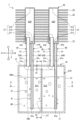
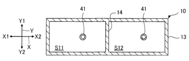
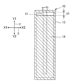
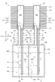
図2は、図1に示す沸騰冷却装置1の断面図である。図3は、図2中のA-A線断面図である。図4は、図2中のB-B線断面図である。なお、図2では、沸騰冷却装置1をX軸およびZ軸を含む平面に平行な切断面が示される。図3では、受熱部10をX軸およびY軸を含む平面に平行な切断面が示される。図4では、受熱部10をY軸およびZ軸を含む平面に平行な切断面が示される。
1-2. Components of the boiling cooling device Fig. 2 is a cross-sectional view of the boiling cooling device 1 shown in Fig. 1. Fig. 3 is a cross-sectional view taken along line A-A in Fig. 2. Fig. 4 is a cross-sectional view taken along line B-B in Fig. 2. Fig. 2 shows a cross-sectional view of the boiling cooling device 1 parallel to a plane including the X-axis and Z-axis. Fig. 3 shows a cross-sectional view of the heat receiving part 10 parallel to a plane including the X-axis and Y-axis. Fig. 4 shows a cross-sectional view of the heat receiving part 10 parallel to a plane including the Y-axis and Z-axis.

1-2a.受熱部
受熱部10は、収容室S10を有する構造体であり、発熱体100からの熱を受ける。収容室S10は、液状の冷媒REを収容する空間である。受熱部10では、発熱体100の熱によって冷媒REが気化されることにより気相冷媒が生成される。
The heat receiving unit 10 is a structure having a storage chamber S10, and receives heat from the heat generating element 100. The storage chamber S10 is a space that stores a liquid refrigerant RE. In the heat receiving unit 10, the refrigerant RE is vaporized by the heat of the heat generating element 100, thereby generating a gas-phase refrigerant.

冷媒REとしては、特に限定されないが、例えば、水等の水系冷媒、メタノール等のアルコール系冷媒、アセトン等のケトン系冷媒、エチレングリコール等のグリコール系冷媒、フロリナート等のフッ化炭素系冷媒、HFC134a等のフロン系冷媒、およびブタン等の炭化水素系冷媒等が挙げられる。なお、冷媒REには、必要に応じて、フッ素系界面活性剤、シリコーン系界面活性剤または炭化水素系界面活性剤等の界面活性剤等が添加されてもよい。また、冷媒REは、前述の冷媒の2種以上を組み合わせてもよい。 Refrigerant RE is not particularly limited, but examples include water-based refrigerants such as water, alcohol-based refrigerants such as methanol, ketone-based refrigerants such as acetone, glycol-based refrigerants such as ethylene glycol, fluorocarbon-based refrigerants such as Fluorinert, fluorocarbon-based refrigerants such as HFC134a, and hydrocarbon-based refrigerants such as butane. If necessary, surfactants such as fluorine-based surfactants, silicone-based surfactants, or hydrocarbon-based surfactants may be added to the refrigerant RE. The refrigerant RE may also be a combination of two or more of the above-mentioned refrigerants.

図2に示す例では、受熱部10は、収容室S10を内部空間として有する箱状をなす容器である。ここで、受熱部10は、底板11と天板12と側壁13と壁部材14とを有する。 In the example shown in FIG. 2, the heat receiving section 10 is a box-shaped container having a storage chamber S10 as an internal space. Here, the heat receiving section 10 has a bottom plate 11, a top plate 12, a side wall 13, and a wall member 14.

底板11および天板12のそれぞれは、Z軸に直交する方向に広がる平板である。ただし、天板12は、底板11に対してZ1方向に位置しており、天板12には、第1管部30および第2管部40との接続のための孔が設けられる。底板11および天板12は、互いに平行となるように配置されており、これらの間には、側壁13が配置される。 The bottom plate 11 and the top plate 12 are each a flat plate extending in a direction perpendicular to the Z axis. However, the top plate 12 is positioned in the Z1 direction relative to the bottom plate 11, and the top plate 12 is provided with holes for connection to the first tube section 30 and the second tube section 40. The bottom plate 11 and the top plate 12 are arranged so as to be parallel to each other, and a side wall 13 is arranged between them.

側壁13は、底板11および天板12の外周同士を全周にわたって連結する。本実施形態では、側壁13の外周面には、発熱体100が接触する。また、側壁13の内側には、壁部材14が配置される。こで、壁部材14は、底板11から天板12に向けて延びており、天板12と壁部材14との間には、隙間d1が形成される。 The side wall 13 connects the outer peripheries of the bottom plate 11 and the top plate 12 together over the entire circumference. In this embodiment, the heating element 100 is in contact with the outer periphery of the side wall 13. In addition, a wall member 14 is disposed inside the side wall 13. Here , the wall member 14 extends from the bottom plate 11 toward the top plate 12, and a gap d1 is formed between the top plate 12 and the wall member 14.

壁部材14は、収容室S10の一部を図2中の左右に二分するように配置され、底板11および側壁13のそれぞれに接続される板状の部材である。ここで、壁部材14は、X軸に直交する面に沿って広がっており、図3に示すように、収容室S10の一部を第1空間S11と第2空間S12とに区分する。また、図4に示すように、壁部材14は、天板12に対向する端縁を除く周縁が全域にわたり底板11および側壁13に接続される。 The wall member 14 is disposed so as to divide a portion of the storage chamber S10 into two halves, left and right, in FIG. 2, and is a plate-like member connected to the bottom plate 11 and the side wall 13. Here, the wall member 14 extends along a plane perpendicular to the X-axis, and divides a portion of the storage chamber S10 into a first space S11 and a second space S12, as shown in FIG. 3. Also, as shown in FIG. 4, the wall member 14 is connected to the bottom plate 11 and the side wall 13 over the entire periphery, except for the edge facing the top plate 12.

図2に示すように、第1空間S11は、壁部材14のX1方向を向く面と底板11と側壁13とで囲まれる凹部である。第2空間S12は、壁部材14のX2方向を向く面と底板11と側壁13とで囲まれる凹部である。 As shown in FIG. 2, the first space S11 is a recess surrounded by the surface of the wall member 14 facing the X1 direction, the bottom plate 11, and the side wall 13. The second space S12 is a recess surrounded by the surface of the wall member 14 facing the X2 direction, the bottom plate 11, and the side wall 13.

本実施形態では、第1空間S11および第2空間S12のそれぞれに液状の冷媒REが収容される。すなわち、本実施形態では、収容室S10の収容される冷媒REが第1空間S11に収容される冷媒REと第2空間S12に収容される冷媒REとに区分される。 In this embodiment, the first space S11 and the second space S12 each contain a liquid refrigerant RE. That is, in this embodiment, the refrigerant RE contained in the storage chamber S10 is divided into the refrigerant RE contained in the first space S11 and the refrigerant RE contained in the second space S12.

ここで、図2に示すように、Z軸が鉛直線となるよう沸騰冷却装置1が傾斜せずに設置される場合、壁部材14のZ1方向での端は、冷媒REの液面RE0よりも上方に位置する。言い換えると、この場合、冷媒REの液面RE0は、壁部材14のZ1方向での端よりも下方に位置する。このため、Z軸が鉛直線である場合、壁部材14と天板12との間の隙間d1を介して第1空間S11と第2空間S12との間での気体状の冷媒REの移動を許容するが、第1空間S11と第2空間S12との間での液状の冷媒REの移動が壁部材14により阻止される。この阻止は、Y1方向にみて時計回りとなるよう鉛直線に対してZ軸がY軸まわりに所定角度範囲内で傾斜しても実現される。なお、壁部材14の作用効果については、後述の図4に基づいて詳述する。 Here, as shown in FIG. 2, when the boiling cooling device 1 is installed without tilting so that the Z axis is a vertical line, the end of the wall member 14 in the Z1 direction is located above the liquid level RE0 of the refrigerant RE. In other words, in this case, the liquid level RE0 of the refrigerant RE is located below the end of the wall member 14 in the Z1 direction. Therefore, when the Z axis is a vertical line, the movement of the gaseous refrigerant RE between the first space S11 and the second space S12 is permitted through the gap d1 between the wall member 14 and the top plate 12, but the movement of the liquid refrigerant RE between the first space S11 and the second space S12 is prevented by the wall member 14. This prevention is also achieved when the Z axis is tilted within a predetermined angle range around the Y axis with respect to the vertical line so as to be clockwise when viewed in the Y1 direction. The action and effect of the wall member 14 will be described in detail based on FIG. 4 described later.

受熱部10は、熱伝導性に優れる材料で構成される。受熱部10の具体的な構成材料としては、例えば、銅、アルミニウムまたはこれらのいずれかの合金等の金属材料が挙げられる。なお、受熱部10の底板11、天板12、側壁13および壁部材14の各部の構成材料は、互いに同じであっても異なってもよい。また、底板11、天板12、側壁13および壁部材14のそれぞれは別部材で構成されてもよいし、底板11、天板12、側壁13および壁部材14は、一体で構成されてもよい。 The heat receiving section 10 is made of a material with excellent thermal conductivity. Specific constituent materials of the heat receiving section 10 include, for example, metal materials such as copper, aluminum, or an alloy of any of these. The constituent materials of each part of the bottom plate 11, top plate 12, side wall 13, and wall member 14 of the heat receiving section 10 may be the same or different. In addition, each of the bottom plate 11, top plate 12, side wall 13, and wall member 14 may be made of separate materials, or the bottom plate 11, top plate 12, side wall 13, and wall member 14 may be made of an integrated body.

ただし、壁部材14は、熱伝導性を有しなくてもよいが、熱伝導性を有する場合、発熱体100から冷媒REに熱を伝達する伝熱面の面積が大きくなるので、冷媒REの核沸騰を効率的に生じさせることができる。また、この場合、冷媒REの核沸騰を促進する観点から、壁部材14の表面は、複数の凹部または複数の凸部を有することが好ましい。当該複数の凹部または当該複数の凸部としては、例えば、切削等の加工による加工痕、ディンプル加工による複数の凹部、ブラスト処理による複数の凹凸部、エッチング処理による凹部パターンまたは凸部パターン、連続空孔を有する多孔質体の表面、押出成形、溶接またはロウ付け等により形成される並列型、格子型または波型のフィン等が挙げられる。 However, the wall member 14 does not have to have thermal conductivity. However, if it does have thermal conductivity, the area of the heat transfer surface that transfers heat from the heating element 100 to the refrigerant RE is increased, so that nucleate boiling of the refrigerant RE can be efficiently generated. In this case, from the viewpoint of promoting nucleate boiling of the refrigerant RE, it is preferable that the surface of the wall member 14 has multiple recesses or multiple protrusions. Examples of the multiple recesses or multiple protrusions include processing marks by machining such as cutting, multiple recesses by dimple processing, multiple uneven portions by blasting, a recess pattern or a protrusion pattern by etching, the surface of a porous body having continuous pores, and parallel, lattice, or wave-shaped fins formed by extrusion molding, welding, brazing, or the like.

以上の受熱部10には、発熱体100が熱的に接続される。本実施形態では、発熱体100が側壁13の外表面に熱的に接続される。ここで、「熱的に接続」とは、次の条件a、bまたはcのいずれかを満たすことをいう。条件a:2つの部材が物理的に直接に接する。条件b:2つの部材が50μm以下の間隙を介して配置される。条件c:2つの部材が10W・m-1・K-1以上の熱伝導率の他の部材を介して物理的に接続される。なお、各条件における2つの部材間には、伝熱グリースおよび接着剤等が存在してもよい。この場合、接着剤は、熱伝導性を高める観点から、熱伝導性のフィラー等を含むことが好ましい。 The heat receiving portion 10 is thermally connected to the heat generating body 100. In this embodiment, the heat generating body 100 is thermally connected to the outer surface of the side wall 13. Here, "thermally connected" means that any one of the following conditions a, b, or c is satisfied. Condition a: The two members are physically in direct contact. Condition b: The two members are arranged with a gap of 50 μm or less. Condition c: The two members are physically connected via another member with a thermal conductivity of 10 W·m −1 ·K −1 or more. Note that a heat transfer grease, adhesive, or the like may be present between the two members in each condition. In this case, it is preferable that the adhesive contains a thermally conductive filler, or the like, from the viewpoint of increasing thermal conductivity.

1-2b.放熱部
放熱部20は、凝縮室S20を有する構造体であり、受熱部10からの熱を放熱する。凝縮室S20は、冷媒REを気化した状態から凝縮液化させる空間である。放熱部20では、受熱部10で生成された気相冷媒が凝縮されることにより液相冷媒が生成される。ここで、放熱部20は、凝縮室S20の気相冷媒を外部の流体との熱交換により放熱することにより凝縮液化させる。当該外部の流体は、凝縮室S20の外部を流動する流体であればよく、特に限定されず、液体でも気体でもよいが、典型的には、例えば空気である。
1-2b. Heat Dissipation Section The heat dissipation section 20 is a structure having a condensation chamber S20, and dissipates heat from the heat receiving section 10. The condensation chamber S20 is a space in which the refrigerant RE is condensed from a vaporized state to a liquid state. In the heat dissipation section 20, the gas-phase refrigerant generated in the heat receiving section 10 is condensed to generate a liquid-phase refrigerant. Here, the heat dissipation section 20 condenses and liquefies the gas-phase refrigerant in the condensation chamber S20 by dissipating heat through heat exchange with an external fluid. The external fluid may be any fluid that flows outside the condensation chamber S20, and is not particularly limited, and may be either a liquid or a gas, but is typically, for example, air.

図2に示す例では、放熱部20は、2個の容器21と複数の放熱フィン22とを有する。2個の容器21のそれぞれは、凝縮室S20を内部空間として有する。容器21は、底板211と天板212と側壁213とを有する。これらで囲まれた空間が凝縮室S20である。底板211および天板212のそれぞれは、Z軸に交差する方向に広がる平板である。ただし、底板211は、天板212に対してZ2方向に位置しており、底板211には、第1管部30および第2管部40との接続のための孔が設けられる。底板211および天板212は、互いに平行となるように配置されており、これらの間には、側壁213が配置される。側壁213は、底板211および天板212の外周同士を全周にわたって連結する。 2, the heat dissipation unit 20 has two containers 21 and a plurality of heat dissipation fins 22. Each of the two containers 21 has a condensation chamber S20 as an internal space. The container 21 has a bottom plate 211, a top plate 212, and a side wall 213. The space surrounded by these is the condensation chamber S20. The bottom plate 211 and the top plate 212 are each a flat plate extending in a direction intersecting the Z axis. However, the bottom plate 211 is located in the Z2 direction relative to the top plate 212, and the bottom plate 211 has holes for connecting to the first tube section 30 and the second tube section 40. The bottom plate 211 and the top plate 212 are arranged so as to be parallel to each other, and the side wall 213 is arranged between them. The side wall 213 connects the outer peripheries of the bottom plate 211 and the top plate 212 over the entire circumference.

本実施形態では、側壁213が円筒状をなしており、凝縮室S20が円柱状をなす。なお、凝縮室S20の形状は、円柱状に限定されず、例えば、角各柱状でもよい。また、側壁213の内周面および外周面の形状は、互いに異なってもよい。 In this embodiment, the side wall 213 is cylindrical, and the condensation chamber S20 is columnar. Note that the shape of the condensation chamber S20 is not limited to a columnar shape, and may be, for example, a rectangular columnar shape. In addition, the shapes of the inner and outer circumferential surfaces of the side wall 213 may be different from each other.

容器21は、熱伝導性に優れる材料で構成される。容器21の具体的な材料としては、例えば、銅、アルミニウムまたはこれらのいずれかの合金等の金属材料が挙げられる。 The container 21 is made of a material with excellent thermal conductivity. Specific examples of the material for the container 21 include metal materials such as copper, aluminum, or an alloy of either of these.

各放熱フィン22は、2個の容器21に熱的に接続される。各放熱フィン22は、平板状の部材である。複数の放熱フィン22は、互いに厚さ方向に間隔を隔てて配置される。各放熱フィン22は、熱伝導性に優れる材料で構成される。放熱フィン22の具体的な材料としては、例えば、銅、アルミニウムまたはこれらのいずれかの合金等の金属材料が挙げられる。各放熱フィン22には、容器21を挿入するための孔が設けられる。放熱フィン22は、例えば、容器21に対して拡管、圧入、接着剤、ネジ止め、ロウ付けまたは溶接等により固定される。 Each heat dissipation fin 22 is thermally connected to two containers 21. Each heat dissipation fin 22 is a flat plate-shaped member. The multiple heat dissipation fins 22 are arranged at intervals from each other in the thickness direction. Each heat dissipation fin 22 is made of a material with excellent thermal conductivity. Specific materials for the heat dissipation fins 22 include metal materials such as copper, aluminum, or an alloy of either of these. Each heat dissipation fin 22 is provided with a hole for inserting the container 21. The heat dissipation fin 22 is fixed to the container 21 by, for example, expanding the tube, pressing, using an adhesive, screwing, brazing, or welding.

なお、放熱フィン22の形状は、図2に示す例に限定されず、任意である。また、放熱フィン22は、必要に応じて設ければよく、省略してもよい。ただし、放熱部20が複数の放熱フィン22を有することにより、冷媒REの気体を効率的に凝縮液化させることができる。 The shape of the heat dissipation fins 22 is not limited to the example shown in FIG. 2 and may be any shape. The heat dissipation fins 22 may be provided as needed, or may be omitted. However, by having the heat dissipation unit 20 have multiple heat dissipation fins 22, the gaseous refrigerant RE can be efficiently condensed and liquefied.

1-2c.第1管部
第1管部30は、受熱部10で冷媒REが気化されることにより生成された気相冷媒を放熱部20に輸送する第1流路S30を有する。本実施形態では、第1管部30は、前述の2個の容器21に対応する2個の蒸気管31で構成される。2個の蒸気管31のそれぞれは、Z軸に沿って直線状に延びており、第1流路S30を内部空間として有する管である。
1-2c. First pipe section The first pipe section 30 has a first flow path S30 that transports the gas-phase refrigerant generated by vaporizing the refrigerant RE in the heat receiving section 10 to the heat dissipating section 20. In this embodiment, the first pipe section 30 is composed of two steam pipes 31 corresponding to the above-mentioned two containers 21. Each of the two steam pipes 31 extends linearly along the Z axis and is a pipe having the first flow path S30 as an internal space.

蒸気管31は、例えば、銅、アルミニウムまたはこれらのいずれかの合金等の金属材料で構成される。また、蒸気管31は、天板12および底板211に対してロウ付け等により固定される。なお、蒸気管31の構成材料は、金属材料に限定されず、例えば、セラミックス材料または樹脂材料等でもよい。 The steam pipe 31 is made of a metal material such as copper, aluminum, or an alloy of these. The steam pipe 31 is fixed to the top plate 12 and the bottom plate 211 by brazing or the like. The material of the steam pipe 31 is not limited to a metal material, and may be, for example, a ceramic material or a resin material.

蒸気管31は、受熱部10および放熱部20のそれぞれに接続されており、受熱部10に向けて開口する開口31aと、放熱部20に向けて開口する開口31bと、を有する。
開口31aは、蒸気管31の内周面31cのZ2方向での端縁で囲まれる空間である。開口31bは、蒸気管31の内周面31cのZ1方向での端縁で囲まれる空間である。
The steam pipe 31 is connected to both the heat receiving portion 10 and the heat radiating portion 20 , and has an opening 31 a that opens toward the heat receiving portion 10 and an opening 31 b that opens toward the heat radiating portion 20 .
The opening 31a is a space surrounded by an edge in the Z2 direction of the inner circumferential surface 31c of the steam pipe 31. The opening 31b is a space surrounded by an edge in the Z1 direction of the inner circumferential surface 31c of the steam pipe 31.

ここで、開口31aは、天板12のZ2方向を向く面である内壁面と同一平面上に位置する。また、2個の蒸気管31のうち、一方の蒸気管31の開口31aは、前述の第1空間S11に向けて開口し、他方の蒸気管31の開口31aは、「第1開口」の一例であり、前述の第2空間S12に向けて開口する。 Here, the opening 31a is located on the same plane as the inner wall surface, which is the surface of the top plate 12 facing the Z2 direction. Furthermore, of the two steam pipes 31, the opening 31a of one steam pipe 31 opens toward the first space S11 described above, and the opening 31a of the other steam pipe 31 is an example of a "first opening" and opens toward the second space S12 described above.

また、蒸気管31の一部は、放熱部20の底板211よりもZ1方向に突出する。したがって、開口31bは、底板211よりもZ1方向に位置する。このため、容器21内で開口31bへ液相冷媒が混入したり、当該液相冷媒により開口31bが塞がれたりすることが低減される。この点については、後述の図5に基づいて詳述する。なお、第1流路S30は、蒸気管31と前述の受熱部10の天板12とにより形成されてもよい。この場合、開口31aは、天板12に設けられる孔により形成される。 In addition, a portion of the steam pipe 31 protrudes in the Z1 direction beyond the bottom plate 211 of the heat dissipation section 20. Therefore, the opening 31b is located in the Z1 direction beyond the bottom plate 211. This reduces the possibility of liquid-phase refrigerant mixing with the opening 31b in the container 21 or blocking the opening 31b with the liquid-phase refrigerant. This will be described in detail later with reference to FIG. 5. The first flow path S30 may be formed by the steam pipe 31 and the top plate 12 of the heat receiving section 10. In this case, the opening 31a is formed by a hole provided in the top plate 12.

第1流路S30は、蒸気管31の内周面31cで囲まれる空間である。第1流路S30は、開口31aを介して収容室S10に連通するとともに、開口31bを介して凝縮室S20に連通する。 The first flow path S30 is a space surrounded by the inner circumferential surface 31c of the steam pipe 31. The first flow path S30 communicates with the storage chamber S10 via the opening 31a and with the condensation chamber S20 via the opening 31b.

図2に示す例では、第1流路S30の幅は、一定である。また、第1流路S30の断面積は、一定である。さらに、第1流路S30の横断面の形状は、円形である。なお、第1流路S30の横断面の形状は、円形に限定されず、例えば、四角形等の多角形、楕円形等でもよい。また、第1流路S30は、屈曲または湾曲する部分を有してもよい。 In the example shown in FIG. 2, the width of the first flow path S30 is constant. Also, the cross-sectional area of the first flow path S30 is constant. Furthermore, the cross-sectional shape of the first flow path S30 is circular. Note that the cross-sectional shape of the first flow path S30 is not limited to a circle, and may be, for example, a polygon such as a square, an ellipse, or the like. Also, the first flow path S30 may have a bent or curved portion.

1-2d.第2管部
第2管部40は、放熱部20で気相冷媒が凝縮されることにより生成された液相冷媒を受熱部10に輸送する第2流路S40を有する。本実施形態では、第2管部40は、前述の2個の容器21に対応する2個の液管41で構成される。2個の液管41のそれぞれは、Z軸に沿って直線状に延びており、第2流路S40を内部空間として有する管である。
1-2d. Second pipe section The second pipe section 40 has a second flow path S40 that transports the liquid-phase refrigerant generated by condensing the gas-phase refrigerant in the heat dissipation section 20 to the heat receiving section 10. In this embodiment, the second pipe section 40 is composed of two liquid pipes 41 corresponding to the above-mentioned two containers 21. Each of the two liquid pipes 41 extends linearly along the Z axis and is a pipe having the second flow path S40 as an internal space.

液管41は、例えば、銅、アルミニウムまたはこれらのいずれかの合金等の金属材料で構成される。また、液管41は、天板12および底板211に対してロウ付け等により固定される。なお、液管41の構成材料は、金属材料に限定されず、例えば、セラミックス材料または樹脂材料等でもよい。また、液管41の構成材料は、蒸気管31の構成材料と同一であってもよいし異なってもよい。 The liquid pipe 41 is made of a metal material such as copper, aluminum, or an alloy of these. The liquid pipe 41 is fixed to the top plate 12 and the bottom plate 211 by brazing or the like. The material of the liquid pipe 41 is not limited to a metal material, and may be, for example, a ceramic material or a resin material. The material of the liquid pipe 41 may be the same as or different from the material of the steam pipe 31.

液管41は、受熱部10および放熱部20のそれぞれに接続されており、受熱部10に向けて開口する開口41aと、放熱部20に向けて開口する開口41bと、を有する。開口41aは、液管41の内周面41cのZ2方向での端縁で囲まれる空間である。開口41bは、液管41の内周面41cのZ1方向での端縁で囲まれる空間である。 The liquid pipe 41 is connected to each of the heat receiving section 10 and the heat dissipation section 20, and has an opening 41a that opens toward the heat receiving section 10 and an opening 41b that opens toward the heat dissipation section 20. The opening 41a is a space surrounded by the edge of the inner surface 41c of the liquid pipe 41 in the Z2 direction. The opening 41b is a space surrounded by the edge of the inner surface 41c of the liquid pipe 41 in the Z1 direction.

ここで、液管41の一部は、受熱部10の天板12よりもZ2方向に突出する。したがって、開口41aは、天板12よりもZ2方向に位置する。本実施形態では、開口41aは、冷媒REの液面RE0よりも下方に位置する。このため、気相冷媒が開口41aに混入され難くすることができる。しかも、開口41aは、発熱体100よりも下方に位置しており、発熱体100と受熱部10とが重なる方向にみて発熱体100に重ならない。このため、冷媒REの核沸騰により生じた気泡が開口41aに入り難くすることができる。また、2個の液管41のうち、一方の液管41の開口41aは、前述の第1空間S11に位置し、他方の液管41の開口41aは、「第2開口」の一例であり、前述の第2空間S12に位置する。 Here, a part of the liquid pipe 41 protrudes in the Z2 direction from the top plate 12 of the heat receiving section 10. Therefore, the opening 41a is located in the Z2 direction from the top plate 12. In this embodiment, the opening 41a is located below the liquid level RE0 of the refrigerant RE. Therefore, it is possible to make it difficult for the gas phase refrigerant to be mixed into the opening 41a. Moreover, the opening 41a is located below the heating element 100 and does not overlap with the heating element 100 when viewed in the direction in which the heating element 100 and the heat receiving section 10 overlap. Therefore, it is possible to make it difficult for bubbles generated by nucleate boiling of the refrigerant RE to enter the opening 41a. Moreover, of the two liquid pipes 41, the opening 41a of one liquid pipe 41 is located in the first space S11 described above, and the opening 41a of the other liquid pipe 41 is an example of a "second opening" and is located in the second space S12 described above.

また、開口41bは、放熱部20の底板211のZ1方向を向く面と同一平面上に位置する。このため、容器21内で開口41bへ液相冷媒を導入しやすくすることができる。この点については、後述の図5に基づいて詳述する。なお、第2流路S40は、液管41と前述の放熱部20の底板211とにより形成されてもよい。この場合、開口41bは、底板211に設けられる孔により形成される。 The opening 41b is located on the same plane as the surface of the bottom plate 211 of the heat dissipation section 20 facing the Z1 direction. This makes it easier to introduce liquid-phase refrigerant into the opening 41b inside the container 21. This will be described in detail later with reference to FIG. 5. The second flow path S40 may be formed by the liquid pipe 41 and the bottom plate 211 of the heat dissipation section 20. In this case, the opening 41b is formed by a hole provided in the bottom plate 211.

第2流路S40は、液管41の内周面41cで囲まれる空間である。第2流路S40は、開口41aを介して収容室S10に連通するとともに、開口41bを介して凝縮室S20に連通する。 The second flow path S40 is a space surrounded by the inner circumferential surface 41c of the liquid pipe 41. The second flow path S40 communicates with the storage chamber S10 via the opening 41a and with the condensation chamber S20 via the opening 41b.

第2流路S40の断面積は、前述の第1流路S30の断面積よりも小さい。すなわち、第1流路S30の断面積は、第2流路S40の断面積よりも大きい。このため、第1流路S30の断面積が第2流路S40の断面積以下である構成に比べて、第1流路S30での気相冷媒の輸送を円滑に行うことができる。なお、第2流路S40の断面積は、第1流路S30の断面積に等しくてもよい。 The cross-sectional area of the second flow path S40 is smaller than the cross-sectional area of the first flow path S30 described above. That is, the cross-sectional area of the first flow path S30 is larger than the cross-sectional area of the second flow path S40. Therefore, the transport of the gas phase refrigerant in the first flow path S30 can be performed more smoothly than in a configuration in which the cross-sectional area of the first flow path S30 is equal to or smaller than the cross-sectional area of the second flow path S40. Note that the cross-sectional area of the second flow path S40 may be equal to the cross-sectional area of the first flow path S30.

図2に示す例では、第2流路S40の幅は、一定である。また、第2流路S40の断面積は、一定である。さらに、第2流路S40の横断面の形状は、円形である。なお、第2流路S40の横断面の形状は、円形に限定されず、例えば、四角形等の多角形、楕円形等でもよい。また、第2流路S40は、屈曲または湾曲する部分を有してもよい。 In the example shown in FIG. 2, the width of the second flow path S40 is constant. The cross-sectional area of the second flow path S40 is also constant. The cross-sectional shape of the second flow path S40 is circular. Note that the cross-sectional shape of the second flow path S40 is not limited to a circle, and may be, for example, a polygon such as a square, an ellipse, or the like. The second flow path S40 may also have a bent or curved portion.

1-3.沸騰冷却装置の使用例
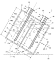
図5は、第1実施形態に係る沸騰冷却装置1の使用例における受熱部10の状態を示す図である。図5では、沸騰冷却装置1がY軸まわりに角度θ1で傾斜して設置された場合の受熱部10の状態が示される。ここで、角度θ1は、水平面F0と受熱部10の底面とのなす角度に等しいか、あるいは、収容室S10の中心線LCまたは液管41の中心線と鉛直線とのなす角度である。具体的には、角度θ1は、45°以下の角度である。なお、中心線LCは、収容室S10の中心を通り、かつ、底板11または天板12に直交する直線である。
1-3. Example of Use of the Boiling Cooling Device FIG. 5 is a diagram showing the state of the heat receiving part 10 in an example of use of the boiling cooling device 1 according to the first embodiment. FIG. 5 shows the state of the heat receiving part 10 when the boiling cooling device 1 is installed at an angle θ1 around the Y axis. Here, the angle θ1 is equal to the angle between the horizontal plane F0 and the bottom surface of the heat receiving part 10, or the angle between the center line LC of the storage chamber S10 or the center line of the liquid pipe 41 and a vertical line. Specifically, the angle θ1 is an angle of 45° or less. The center line LC is a straight line that passes through the center of the storage chamber S10 and is perpendicular to the bottom plate 11 or the top plate 12.

図5に示すように、沸騰冷却装置1の傾斜角度が角度θ1である場合でも、壁部材14のZ1方向での端は、冷媒REの液面RE0よりも上方に位置する。言い換えると、この場合でも、冷媒REの液面RE0は、壁部材14のZ1方向での端よりも下方に位置する。このため、この場合でも、壁部材14と天板12との間の隙間d1を介して第1空間S11と第2空間S12との間での気体状の冷媒REの移動を許容するが、第1空間S11と第2空間S12との間での液状の冷媒REの移動が壁部材14により阻止される。なお、沸騰冷却装置1の傾斜角度が角度θ1である場合、壁部材14のZ1方向での端が液面RE0に一致してもよい。 5, even when the inclination angle of the boiling cooling device 1 is angle θ1, the end of the wall member 14 in the Z1 direction is located above the liquid level RE0 of the refrigerant RE. In other words, even in this case, the liquid level RE0 of the refrigerant RE is located below the end of the wall member 14 in the Z1 direction. Therefore, even in this case, the movement of the gaseous refrigerant RE between the first space S11 and the second space S12 is permitted through the gap d1 between the wall member 14 and the top plate 12, but the movement of the liquid refrigerant RE between the first space S11 and the second space S12 is prevented by the wall member 14. Note that when the inclination angle of the boiling cooling device 1 is angle θ1, the end of the wall member 14 in the Z1 direction may coincide with the liquid level RE0.

図5には、沸騰冷却装置1の傾斜角度が角度θ1である場合の液面RE0が実線で示される。また、図5には、沸騰冷却装置1を傾斜させない場合の液面RE0が一点鎖線で示される。さらに、図5には、壁部材14を省略した場合の冷媒REの液面RE0が二点鎖線で示される。 In FIG. 5, the liquid level RE0 when the inclination angle of the boiling cooling device 1 is angle θ1 is shown by a solid line. Also, in FIG. 5, the liquid level RE0 when the boiling cooling device 1 is not inclined is shown by a dashed line. Furthermore, in FIG. 5, the liquid level RE0 of the refrigerant RE when the wall member 14 is omitted is shown by a two-dot chain line.

図5に示すように、沸騰冷却装置1を傾斜させた場合、第1空間S11の底面が第2空間S12の底面よりも上方に位置する。この場合であっても、第1空間S11から第2空間S12への液状の冷媒REの移動が壁部材14により阻止されるので、壁部材14を省略した場合に比べて、冷媒REの液面RE0と蒸気管31の開口31aとの間の距離を大きくすることができる。このため、沸騰冷却装置1を傾斜させた場合でも、冷媒REによる開口31aの封鎖を低減することができる。 As shown in FIG. 5, when the boiling cooling device 1 is tilted, the bottom surface of the first space S11 is located above the bottom surface of the second space S12. Even in this case, the movement of the liquid refrigerant RE from the first space S11 to the second space S12 is prevented by the wall member 14, so the distance between the liquid level RE0 of the refrigerant RE and the opening 31a of the vapor pipe 31 can be made larger than when the wall member 14 is omitted. Therefore, even when the boiling cooling device 1 is tilted, the blocking of the opening 31a by the refrigerant RE can be reduced.

ここで、液面RE0は、第1空間S11および第2空間S12のそれぞれで個別にY軸まわりにX軸に対して傾斜する。したがって、第1空間S11および第2空間S12のそれぞれでは、X軸に沿う方向で液面RE0の中央と天板12との間の距離は、ほとんど変化しない。 Here, the liquid level RE0 is inclined around the Y axis with respect to the X axis in each of the first space S11 and the second space S12 individually. Therefore, in each of the first space S11 and the second space S12, the distance between the center of the liquid level RE0 and the top plate 12 in the direction along the X axis hardly changes.

図5に示す例では、開口31aが第1空間S11および第2空間S12のそれぞれのX軸に沿う方向での中央に位置する。このため、冷媒REの液面RE0と蒸気管31の開口31aとの間の距離は、沸騰冷却装置1を傾斜させない場合と比べて、ほとんど変化しない。 In the example shown in FIG. 5, the opening 31a is located at the center of the first space S11 and the second space S12 in the direction along the X-axis. Therefore, the distance between the liquid level RE0 of the refrigerant RE and the opening 31a of the vapor pipe 31 hardly changes compared to when the boiling cooling device 1 is not tilted.

Z軸に沿う方向での壁部材14の長さ、すなわち壁部材14の高さhは、前述のように、沸騰冷却装置1の傾斜角度が角度θ1である場合でも、壁部材14のZ1方向での端が液面RE0よりも上方に位置するよう設定される。 The length of the wall member 14 in the direction along the Z axis, i.e., the height h of the wall member 14, is set so that the end of the wall member 14 in the Z1 direction is positioned above the liquid level RE0, even when the inclination angle of the boiling cooling device 1 is angle θ1, as described above.

ここで、高さhは、高さH1よりも高いことが好ましい。この場合、前述のような壁部材14による効果が好適に得られる。ただし、高さH1は、以下の式(1)により求められる。
H1=(b-(a-L)/tanθ2) (1)
式(1)中、aは、X軸に沿う方向での第2空間S12の長さ[mm]である。bは、Z軸に沿う方向での収容室S10の長さ[mm]である。Lは、第2空間S12に対応する開口31aについて、X軸に沿う方向での開口31aと側壁13との間の距離[mm]である。θ2は、水平面F0とZ軸とのなす角度[°]であり、θ2=90[°]-θ1の関係を満たす。
Here, it is preferable that the height h is greater than the height H1. In this case, the effect of the wall member 14 as described above can be suitably obtained. However, the height H1 can be calculated by the following formula (1).
H1=(b-(a-L)/tanθ2) (1)
In formula (1), a is the length [mm] of the second space S12 in the direction along the X-axis. b is the length [mm] of the storage chamber S10 in the direction along the Z-axis. L is the distance [mm] between the opening 31a corresponding to the second space S12 and the side wall 13 in the direction along the X-axis. θ2 is the angle [°] between the horizontal plane F0 and the Z-axis, and satisfies the relationship θ2=90[°]-θ1.

また、図5に示すように、沸騰冷却装置1の傾斜角度が角度θ1である場合、蒸気管31が液管41に対して上方に位置する。このため、前述のように開口31aと液面RE0との間の距離を大きくしつつ、蒸気管31と側壁13または壁部材14との間に液管41を配置するための領域を十分に確保することができる。 Also, as shown in FIG. 5, when the inclination angle of the boiling cooling device 1 is angle θ1, the steam pipe 31 is positioned above the liquid pipe 41. Therefore, while increasing the distance between the opening 31a and the liquid level RE0 as described above, a sufficient area can be secured between the steam pipe 31 and the side wall 13 or wall member 14 to place the liquid pipe 41.

図6は、第1実施形態に係る沸騰冷却装置1の使用例における放熱部20の状態を示す図である。図6では、前述の図5に示すように沸騰冷却装置1がY軸まわりに傾斜して設置された場合の放熱部20の状態が示される。 Figure 6 is a diagram showing the state of the heat dissipation section 20 in an example of use of the boiling cooling device 1 according to the first embodiment. Figure 6 shows the state of the heat dissipation section 20 when the boiling cooling device 1 is installed tilted around the Y axis as shown in Figure 5 above.

図6に示すように、沸騰冷却装置1の傾斜角度が角度θ1である場合、開口41bが開口31bに対して下方に位置する。このため、開口41bが開口31bに対して上方に位置する構成に比べて、容器21から開口41bに液相冷媒を導入させやすい。しかも、本実施形態では、前述のように開口41bが容器21の底板211の内壁面に開口するので、当該内壁面に沿って液相冷媒を開口41bに円滑に案内することができる。 As shown in FIG. 6, when the inclination angle of the boiling cooling device 1 is angle θ1, the opening 41b is located below the opening 31b. Therefore, it is easier to introduce the liquid refrigerant from the container 21 to the opening 41b compared to a configuration in which the opening 41b is located above the opening 31b. Moreover, in this embodiment, as described above, the opening 41b opens on the inner wall surface of the bottom plate 211 of the container 21, so the liquid refrigerant can be smoothly guided along the inner wall surface to the opening 41b.

また、開口31bが開口41bに対して上方に位置するので、開口31bが開口41bに対して下方に位置する構成に比べて、開口31bが容器21内の液相冷媒により塞がれ難い。しかも、本実施形態では、前述のように開口31bが底板211よりもZ1方向に位置するので、容器21内に溜まる液相冷媒の液面よりも上方に開口31bを位置させることができる。このため、容器21内で開口31bへ液相冷媒が混入したり、当該液相冷媒により開口31bが塞がれたりすることが好適に低減される。 In addition, because opening 31b is located above opening 41b, opening 31b is less likely to be blocked by the liquid-phase refrigerant in container 21 compared to a configuration in which opening 31b is located below opening 41b. Moreover, in this embodiment, opening 31b is located in the Z1 direction above bottom plate 211 as described above, so opening 31b can be positioned above the liquid level of the liquid-phase refrigerant that accumulates in container 21. This effectively reduces the liquid-phase refrigerant from entering opening 31b in container 21 and blocking opening 31b with the liquid-phase refrigerant.

1-4.まとめ
以上の沸騰冷却装置1は、前述のように、受熱部10と放熱部20と第1管部30と第2管部40とを有する。受熱部10は、冷媒REを収容する収容室S10を有し、発熱体100からの熱を受ける。放熱部20は、受熱部10からの熱を放熱する。第1管部30は、受熱部10で冷媒REが気化されることにより生成された気相冷媒を放熱部20に輸送する。第2管部40は、放熱部20で気相冷媒が凝縮されることにより生成された液相冷媒を受熱部10に輸送する。
1-4. Summary As described above, the boiling cooling device 1 has the heat receiving section 10, the heat dissipating section 20, the first pipe section 30, and the second pipe section 40. The heat receiving section 10 has an accommodation chamber S10 that accommodates the refrigerant RE, and receives heat from the heating element 100. The heat dissipating section 20 dissipates heat from the heat receiving section 10. The first pipe section 30 transports the gas phase refrigerant generated by vaporizing the refrigerant RE in the heat receiving section 10 to the heat dissipating section 20. The second pipe section 40 transports the liquid phase refrigerant generated by condensing the gas phase refrigerant in the heat dissipating section 20 to the heat receiving section 10.

そのうえで、受熱部10は、収容室S10の少なくとも一部を第1空間S11と第2空間S12とに仕切る壁部材14を有する。ここで、第1管部30は、第2空間S12に向けて開口する第1開口としての開口31aを有する。また、壁部材14の少なくとも一部は、収容室S10に収容される液状の冷媒REの液面RE0よりも上方に位置する。そして、壁部材14は、第1空間S11から第1開口としての開口31aへの液状の冷媒REの移動を阻止する。 The heat receiving section 10 has a wall member 14 that divides at least a portion of the storage chamber S10 into a first space S11 and a second space S12. Here, the first pipe section 30 has an opening 31a as a first opening that opens toward the second space S12. Also, at least a portion of the wall member 14 is located above the liquid level RE0 of the liquid refrigerant RE stored in the storage chamber S10. The wall member 14 prevents the liquid refrigerant RE from moving from the first space S11 to the opening 31a as the first opening.

以上の沸騰冷却装置では、収容室S10に収容される液状の冷媒REの液面RE0よりも上方に壁部材14の少なくとも一部が位置するので、収容室S10の中心線LCが鉛直線VLに対して傾斜する場合でも、壁部材14が第1空間S11から第1開口としての開口31aへの液状の冷媒REの移動を阻止することができる。このため、沸騰冷却装置1を傾斜した姿勢で設置した場合でも、冷媒REが第1開口としての開口31aを塞いでしまうことを低減することができる。この結果、沸騰冷却装置1の設置姿勢によらず、受熱部10から第1管部30、放熱部20および第2管部40をこの順に通って受熱部10に戻るという冷媒REの循環が従来に比べて円滑に行われるので、冷却性能の低下を低減することができる。 In the above boiling cooling device, at least a part of the wall member 14 is located above the liquid level RE0 of the liquid refrigerant RE contained in the storage chamber S10, so that even if the center line LC of the storage chamber S10 is inclined with respect to the vertical line VL, the wall member 14 can prevent the liquid refrigerant RE from moving from the first space S11 to the opening 31a as the first opening. Therefore, even if the boiling cooling device 1 is installed in an inclined position, it is possible to reduce the refrigerant RE from blocking the opening 31a as the first opening. As a result, regardless of the installation position of the boiling cooling device 1, the circulation of the refrigerant RE from the heat receiving part 10 through the first pipe part 30, the heat dissipation part 20, and the second pipe part 40 in this order and returning to the heat receiving part 10 is performed more smoothly than in the past, so that the deterioration of cooling performance can be reduced.

ここで、第1空間S11と第2空間S12とが収容室S10内で互いに連通するので、第1空間S11および第2空間S12のそれぞれが独立した空間である構成に比べて、沸騰冷却装置1の製造時における収容室S10への冷媒REの充填が簡単に済むという利点がある。また、中心線LCが鉛直線VLに対して傾斜する場合、前述の放熱フィン22が水平面F0に対して傾斜するので、放熱フィン22が水平面F0に対して平行である場合に比べて、放熱フィン22に沿って気流を生じさせやすく、放熱部20の放熱性を高めることができる。 Here, since the first space S11 and the second space S12 communicate with each other within the storage chamber S10, there is an advantage that the refrigerant RE can be easily filled into the storage chamber S10 during the manufacture of the boiling cooling device 1, compared to a configuration in which the first space S11 and the second space S12 are each independent spaces. In addition, when the center line LC is inclined with respect to the vertical line VL, the aforementioned heat dissipation fins 22 are inclined with respect to the horizontal plane F0, so that it is easier to generate an airflow along the heat dissipation fins 22, compared to when the heat dissipation fins 22 are parallel to the horizontal plane F0, and the heat dissipation performance of the heat dissipation section 20 can be improved.

本実施形態では、前述のように、壁部材14は、収容室S10に収容される液状の冷媒REを、第1空間S11に収容される冷媒REと第2空間S12に収容される冷媒REとに区分する。このため、1つの空間に液状の冷媒REを収容する構成に比べて、沸騰冷却装置1を傾斜した姿勢で設置した場合の冷媒REの液面RE0と第1開口としての開口31aとの間の距離を大きくすることができる。 In this embodiment, as described above, the wall member 14 divides the liquid refrigerant RE contained in the storage chamber S10 into the refrigerant RE contained in the first space S11 and the refrigerant RE contained in the second space S12. Therefore, compared to a configuration in which the liquid refrigerant RE is contained in one space, the distance between the liquid level RE0 of the refrigerant RE and the opening 31a as the first opening when the boiling cooling device 1 is installed in an inclined position can be made larger.

また、前述のように、第2管部40は、第2空間S12に向けて開口する第2開口としての開口41aを有する。したがって、第1開口としての開口31aおよび第2開口としての開口41aの双方が第2空間S12に向けて開口する。 As described above, the second tube portion 40 has an opening 41a as a second opening that opens toward the second space S12. Therefore, both the opening 31a as a first opening and the opening 41a as a second opening open toward the second space S12.

そのうえで、第1開口としての開口31aは、第2空間S12に収容される液状の冷媒REの液面RE0よりも上方に位置する。このため、第2空間S12で生じた気相冷媒を円滑に第1開口としての開口31aに導入することができる。 In addition, the opening 31a as the first opening is located above the liquid level RE0 of the liquid refrigerant RE contained in the second space S12. Therefore, the gas phase refrigerant generated in the second space S12 can be smoothly introduced into the opening 31a as the first opening.

一方、第2開口としての開口41aは、第2空間S12に収容される液状の冷媒REの液面RE0よりも下方に位置する。このため、第2空間S12で生じた気相冷媒が第2開口としての開口41aに混入するのを低減することができる。しかも、第1開口としての開口31aおよび第2開口としての開口41aの双方が第2空間S12に向けて開口するので、第1管部30および第2管部40を互いに近づけて配置することができる。この結果、沸騰冷却装置1を傾斜した姿勢で設置した場合に、第2開口としての開口41aが冷媒REに接触したり離反したりすることを低減することができる。 On the other hand, the opening 41a as the second opening is located below the liquid level RE0 of the liquid refrigerant RE contained in the second space S12. This reduces the intrusion of the gas phase refrigerant generated in the second space S12 into the opening 41a as the second opening. Moreover, since both the opening 31a as the first opening and the opening 41a as the second opening open toward the second space S12, the first pipe section 30 and the second pipe section 40 can be arranged close to each other. As a result, when the boiling cooling device 1 is installed in an inclined position, it is possible to reduce the opening 41a as the second opening coming into contact with or separating from the refrigerant RE.

さらに、前述のように、第1管部30は、受熱部10から放熱部20に気相冷媒を輸送する複数の蒸気管31を有する。複数の蒸気管31は、第1開口としての開口31aを有する蒸気管31と、第1空間S11に向けて開口する開口31aを有する蒸気管31と、を含む。また、第2管部40は、放熱部20から受熱部10に液相冷媒を輸送する複数の液管41を有する。複数の液管41は、第2開口としての開口41aを有する液管41と、第1空間S11に向けて開口する開口41aを有する液管41と、を含む。 Furthermore, as described above, the first pipe section 30 has a plurality of vapor pipes 31 that transport the gas-phase refrigerant from the heat receiving section 10 to the heat dissipating section 20. The plurality of vapor pipes 31 includes a vapor pipe 31 having an opening 31a as a first opening, and a vapor pipe 31 having an opening 31a that opens toward the first space S11. The second pipe section 40 has a plurality of liquid pipes 41 that transport the liquid-phase refrigerant from the heat dissipating section 20 to the heat receiving section 10. The plurality of liquid pipes 41 includes a liquid pipe 41 having an opening 41a as a second opening, and a liquid pipe 41 having an opening 41a that opens toward the first space S11.

このように複数の蒸気管31および複数の液管41を用いることにより、冷媒REの循環効率を高めることができる。また、このように複数の蒸気管31および複数の液管41を有する構成では、収容室S10の中心線LCからずれた位置に蒸気管31および液管41が配置される。このため、当該構成では、沸騰冷却装置1を傾斜した姿勢で設置した場合に、蒸気管31の開口が液状の冷媒REにより封鎖されないようにするうえで、前述の壁部材14を設けることは有用である。 By using multiple steam pipes 31 and multiple liquid pipes 41 in this manner, the circulation efficiency of the refrigerant RE can be increased. Furthermore, in a configuration having multiple steam pipes 31 and multiple liquid pipes 41 in this manner, the steam pipes 31 and liquid pipes 41 are positioned at positions offset from the center line LC of the storage chamber S10. Therefore, in this configuration, when the boiling cooling device 1 is installed in an inclined position, it is useful to provide the wall member 14 described above in order to prevent the opening of the steam pipe 31 from being blocked by the liquid refrigerant RE.

また、前述のように、壁部材14は、収容室S10の底面から上方に延びる。このため、壁部材14を板材で構成することができる。この結果、沸騰冷却装置1の構成または製造の簡単化を図ることができる。 As described above, the wall member 14 extends upward from the bottom surface of the storage chamber S10. Therefore, the wall member 14 can be made of a plate material. As a result, the configuration and manufacturing of the boiling cooling device 1 can be simplified.

さらに、前述のように、壁部材14の高さをhとし、壁部材14の厚さ方向に沿う第2空間S12の長さをaとし、壁部材14の高さ方向での収容室S10の長さをbとし、壁部材14の厚さ方向での第1開口としての開口31aと収容室S10の側面との間の距離をLとし、壁部材14の高さ方向と水平面F0とのなす角度をθ2としたとき、θ2が45°よりも小さい場合、h>(b-(a-L)/tanθ2)の関係を満たすことが好ましい。 Furthermore, as described above, when the height of the wall member 14 is h, the length of the second space S12 along the thickness direction of the wall member 14 is a, the length of the storage chamber S10 in the height direction of the wall member 14 is b, the distance between the opening 31a as the first opening in the thickness direction of the wall member 14 and the side surface of the storage chamber S10 is L, and the angle between the height direction of the wall member 14 and the horizontal plane F0 is θ2, it is preferable that the relationship h>(b-(a-L)/tan θ2) is satisfied when θ2 is smaller than 45°.

この関係を満たす場合、この関係を満たさない場合に比べて、収容室S10内の冷媒REの収容率を高めつつ、第1開口としての開口31aが液状の冷媒REにより封鎖されることを低減することができる。 When this relationship is satisfied, the storage rate of the refrigerant RE in the storage chamber S10 can be increased while reducing the blocking of the opening 31a as the first opening by the liquid refrigerant RE, compared to when this relationship is not satisfied.

また、前述のように、受熱部10は、側方から発熱体100からの熱を受ける。このとき、沸騰冷却装置1を傾斜した姿勢で設置した場合でも、受熱部10と発熱体100とが並ぶ方向にみて、液状の冷媒REと発熱体100とが重なる面積の低下を低減することができる。したがって、沸騰冷却装置1を傾斜した姿勢で設置した場合でも、発熱体100から受熱部10の液状の冷媒REに効率的に熱を伝えることができる。 As mentioned above, the heat receiving section 10 receives heat from the heating element 100 from the side. In this case, even if the boiling cooling device 1 is installed in an inclined position, the reduction in the overlapping area between the liquid refrigerant RE and the heating element 100 can be reduced when viewed in the direction in which the heat receiving section 10 and the heating element 100 are aligned. Therefore, even if the boiling cooling device 1 is installed in an inclined position, heat can be efficiently transferred from the heating element 100 to the liquid refrigerant RE of the heat receiving section 10.

2.第2実施形態
以下、本発明の第2実施形態について説明する。以下に例示する形態において作用や機能が前述の実施形態と同様である要素については、前述の実施形態の説明で使用した符号を流用して各々の詳細な説明を適宜に省略する。
2. Second embodiment Hereinafter, a second embodiment of the present invention will be described. In the following exemplary embodiment, for elements whose actions and functions are similar to those of the above-mentioned embodiment, the reference numerals used in the description of the above-mentioned embodiment will be used, and detailed descriptions of each will be omitted as appropriate.

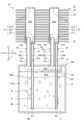
図7は、第2実子形態に係る沸騰冷却装置1Aの断面図である。図8は、図7中のC-C線断面図である。図9は、図7中のD-D線断面図である。沸騰冷却装置1Aは、受熱部10に代えて受熱部10Aを有する以外は、前述の第1実施形態の沸騰冷却装置1と同様である。受熱部10Aは、壁部材14に代えて壁部材15を有する以外は、受熱部10と同様である。 Figure 7 is a cross-sectional view of the boiling cooling device 1A according to the second embodiment. Figure 8 is a cross-sectional view taken along line C-C in Figure 7. Figure 9 is a cross-sectional view taken along line D-D in Figure 7. The boiling cooling device 1A is similar to the boiling cooling device 1 of the first embodiment described above, except that it has a heat receiving portion 10A instead of the heat receiving portion 10. The heat receiving portion 10A is similar to the heat receiving portion 10, except that it has a wall member 15 instead of the wall member 14.

壁部材15は、側壁13のX1方向を向く内壁面からX1方向に延びており、側壁13のX2方向を向く内壁面と壁部材15との間には、隙間d2が形成される。 The wall member 15 extends in the X1 direction from the inner wall surface of the side wall 13 facing the X1 direction, and a gap d2 is formed between the inner wall surface of the side wall 13 facing the X2 direction and the wall member 15.

壁部材15は、収容室S10一部を図7中の上下に二分するように配置され、側壁13に接続される板状の部材である。ここで、壁部材15は、Z軸に直交する面に沿って広がっており、図7に示すように、収容室S10の一部を第1空間S13と第2空間S14とに区分する。また、図8に示すように、壁部材15は、側壁13のX2方向を向く内平面に対向する端縁を除く周縁が全域にわたり側壁13に接続される。 The wall member 15 is a plate-like member that is disposed so as to divide a portion of the storage chamber S10 into two, the top and bottom, as shown in FIG. 7, and is connected to the side wall 13. Here, the wall member 15 extends along a plane perpendicular to the Z axis, and divides a portion of the storage chamber S10 into a first space S13 and a second space S14, as shown in FIG. 7. Also, as shown in FIG. 8, the wall member 15 is connected to the side wall 13 over the entire periphery, except for the edge that faces the inner plane of the side wall 13 facing the X2 direction.

壁部材15は、Z軸に沿う方向にみて、図7中の右側の蒸気管31および液管41に重なる位置に配置される。図7に示す例では、壁部材15には、貫通孔15aが設けられる。貫通孔15aは、X軸に沿う方向に並ぶ2個の液管41のうちのX2方向に位置する一方の液管41が挿入される孔である。当該一方の液管41は、必要に応じて、壁部材15に対して拡管、圧入、接着剤、ネジ止め、ロウ付けまたは溶接等により固定される。また、貫通孔15aを通じて冷媒REが第1空間S13から第2空間S14へ移動しないよう、貫通孔15aの内壁面と液管41の外周面との隙間が塞がれる。なお、貫通孔15aが省略されてもよい。この場合、液管41は、例えば、壁部材15を迂回するように下方に延びるよう、屈曲または湾曲する部分を有する。 The wall member 15 is arranged at a position overlapping the steam pipe 31 and the liquid pipe 41 on the right side in FIG. 7 when viewed in the direction along the Z axis. In the example shown in FIG. 7, a through hole 15a is provided in the wall member 15. The through hole 15a is a hole into which one of the two liquid pipes 41 arranged in the direction along the X axis, which is located in the X2 direction, is inserted. The one liquid pipe 41 is fixed to the wall member 15 by expanding, press-fitting, adhesive, screwing, brazing, welding, or the like as necessary. In addition, the gap between the inner wall surface of the through hole 15a and the outer circumferential surface of the liquid pipe 41 is blocked so that the refrigerant RE does not move from the first space S13 to the second space S14 through the through hole 15a. Note that the through hole 15a may be omitted. In this case, the liquid pipe 41 has a bent or curved portion so as to extend downward to bypass the wall member 15, for example.

ここで、図7に示すように、Z軸が鉛直線となるよう沸騰冷却装置1が傾斜せずに設置される場合、壁部材15は、冷媒REの液面RE0に対して上方に位置する。したがって、第1空間S13には、液状の冷媒REが存在するが、第2空間S14には、液状の冷媒が実質的に存在しない。 As shown in FIG. 7, when the boiling cooling device 1 is installed without tilting so that the Z axis is a vertical line, the wall member 15 is located above the liquid level RE0 of the refrigerant RE. Therefore, liquid refrigerant RE is present in the first space S13, but liquid refrigerant is substantially absent in the second space S14.

図10は、第2実施形態に係る沸騰冷却装置1Aの使用例における受熱部10Aの状態を示す図である。図10では、沸騰冷却装置1がY軸まわりに角度θ1で傾斜して設置された場合の受熱部10Aの状態が示される。 Figure 10 is a diagram showing the state of the heat receiving part 10A in a usage example of the boiling cooling device 1A according to the second embodiment. Figure 10 shows the state of the heat receiving part 10A when the boiling cooling device 1 is installed at an angle θ1 around the Y axis.

図10に示すように、沸騰冷却装置1Aの傾斜角度が角度θ1である場合、壁部材15が第1空間S13から第2空間S14に液状の冷媒REが移動するのを阻止する。このため、この場合でも、第1空間S13には、液状の冷媒REが存在するが、第2空間S14には、液状の冷媒が実質的に存在しない。 As shown in FIG. 10, when the inclination angle of the boiling cooling device 1A is angle θ1, the wall member 15 prevents the liquid refrigerant RE from moving from the first space S13 to the second space S14. Therefore, even in this case, liquid refrigerant RE is present in the first space S13, but substantially no liquid refrigerant is present in the second space S14.

図10には、沸騰冷却装置1Aの傾斜角度が角度θ1である場合の液面RE0が実線で示される。また、図10には、沸騰冷却装置1を傾斜させない場合の液面RE0が一点鎖線で示される。さらに、図10には、壁部材14を省略した場合の冷媒REの液面RE0が二点鎖線で示される。 In FIG. 10, the liquid level RE0 when the inclination angle of the boiling cooling device 1A is angle θ1 is shown by a solid line. Also, in FIG. 10, the liquid level RE0 when the boiling cooling device 1 is not inclined is shown by a dashed line. Furthermore, in FIG. 10, the liquid level RE0 of the refrigerant RE when the wall member 14 is omitted is shown by a two-dot chain line.

図10に示すように、沸騰冷却装置1Aを傾斜させた場合、第1空間S13から第2空間S14への液状の冷媒REの移動が壁部材14により阻止されるので、壁部材15を省略した場合のように液面RE0が開口31aに接近することが防止される。このため、沸騰冷却装置1Aを傾斜させた場合でも、冷媒REによる開口31aの封鎖を低減することができる。 As shown in FIG. 10, when the boiling cooling device 1A is tilted, the movement of the liquid refrigerant RE from the first space S13 to the second space S14 is prevented by the wall member 14, so the liquid level RE0 is prevented from approaching the opening 31a as in the case where the wall member 15 is omitted. Therefore, even when the boiling cooling device 1A is tilted, the blocking of the opening 31a by the refrigerant RE can be reduced.

X軸に沿う方向での壁部材15の長さ、すなわち壁部材14の高さhは、沸騰冷却装置1Aの傾斜角度が角度θ1である場合でも、壁部材15のX1方向での端が液面RE0よりも上方に位置するよう設定される。 The length of the wall member 15 in the direction along the X-axis, i.e., the height h of the wall member 14, is set so that the end of the wall member 15 in the X1 direction is located above the liquid level RE0, even when the inclination angle of the boiling cooling device 1A is angle θ1.

ここで、高さhは、高さH2よりも高いことが好ましい。この場合、前述のような壁部材15による効果が好適に得られる。ただし、高さH2は、以下の式(2)により求められる。
H2=(L+c×tanθ2) (2)
式(2)中、cは、Z軸に沿う方向での第2空間S14の長さ[mm]である。Lは、2個の開口31aのうち壁部材15に近いほうの開口31aについて、X軸に沿う方向での開口31aと側壁13との間の距離[mm]である。θ2は、水平面F0とZ軸とのなす角度[°]であり、θ2=90[°]-θ1の関係を満たす。
Here, it is preferable that the height h is greater than the height H2. In this case, the effect of the wall member 15 as described above can be suitably obtained. However, the height H2 can be calculated by the following formula (2).
H2=(L+c×tanθ2) (2)
In formula (2), c is the length [mm] of the second space S14 in the direction along the Z axis. L is the distance [mm] between the opening 31a and the side wall 13 in the direction along the X axis for the opening 31a closer to the wall member 15 out of the two openings 31a. θ2 is the angle [°] between the horizontal plane F0 and the Z axis, and satisfies the relationship θ2=90[°]-θ1.

以上の第2実施形態によっても、前述の第1実施形態と同様、冷却性能の低下を低減することができる。本実施形態では、前述のように、壁部材15は、収容室S10に収容される液状の冷媒REの液面RE0よりも上方に位置する。このため、収容室S10に収容される液状の冷媒REを第1空間S13と第2空間S14とに区分しなくても、第1開口としての開口31aが液状の冷媒REにより封鎖されることを低減することができる。 The second embodiment described above can also reduce the deterioration of cooling performance, as in the first embodiment described above. In this embodiment, as described above, the wall member 15 is located above the liquid level RE0 of the liquid refrigerant RE contained in the storage chamber S10. Therefore, even if the liquid refrigerant RE contained in the storage chamber S10 is not divided into the first space S13 and the second space S14, it is possible to reduce the blocking of the opening 31a as the first opening by the liquid refrigerant RE.

また、前述のように、第2管部40は、第1空間S13に向けて開口する第2開口としての開口41aを有する。このため、第2管部40からの液相冷媒を第1空間S13に排出することができる。 As described above, the second pipe section 40 has an opening 41a as a second opening that opens toward the first space S13. Therefore, the liquid phase refrigerant from the second pipe section 40 can be discharged into the first space S13.

そのうえで、第1開口としての開口31aは、壁部材15よりも上方に位置する。このため、第1空間S13から第1開口としての開口31aへの液状の冷媒REの移動を壁部材15により阻止することができる。 In addition, the opening 31a serving as the first opening is located above the wall member 15. Therefore, the wall member 15 can prevent the movement of liquid refrigerant RE from the first space S13 to the opening 31a serving as the first opening.

一方、第2開口としての開口41aは、第1空間S13に収容される液状の冷媒REの液面RE0よりも下方に位置する。第1空間S13で生じた気相冷媒が第2開口としての開口41aに混入するのを低減することができる。 On the other hand, the opening 41a as the second opening is located below the liquid level RE0 of the liquid refrigerant RE contained in the first space S13. This can reduce the intrusion of the gas phase refrigerant generated in the first space S13 into the opening 41a as the second opening.

さらに、前述のように、第1管部30は、受熱部10から放熱部20に気相冷媒を輸送する複数の蒸気管31を有する。複数の蒸気管31は、第1開口としての開口31aを有する蒸気管31と、壁部材15の厚さ方向にみて壁部材15に重ならない蒸気管31と、を含む。また、第2管部40は、放熱部20から受熱部10に液相冷媒を輸送する複数の液管41を有する。複数の液管41は、第2開口としての開口41aを有する液管41と、壁部材15の厚さ方向にみて壁部材15に重ならない液管41と、を含む。 Furthermore, as described above, the first pipe section 30 has a plurality of vapor pipes 31 that transport the gas-phase refrigerant from the heat receiving section 10 to the heat dissipating section 20. The plurality of vapor pipes 31 include a vapor pipe 31 having an opening 31a as a first opening, and a vapor pipe 31 that does not overlap the wall member 15 when viewed in the thickness direction of the wall member 15. The second pipe section 40 has a plurality of liquid pipes 41 that transport the liquid-phase refrigerant from the heat dissipating section 20 to the heat receiving section 10. The plurality of liquid pipes 41 include a liquid pipe 41 having an opening 41a as a second opening, and a liquid pipe 41 that does not overlap the wall member 15 when viewed in the thickness direction of the wall member 15.

このように複数の蒸気管31および複数の液管41を用いることにより、冷媒REの循環効率を高めることができる。また、このように複数の蒸気管31および複数の液管41を有する構成では、収容室S10の中心線LCからずれた位置に蒸気管31および液管41が設けられる。このため、当該構成では、沸騰冷却装置1を傾斜した姿勢で設置した場合に、蒸気管31の開口が液状の冷媒REにより封鎖されないようにするうえで、前述の壁部材15を設けることは有用である。 By using multiple steam pipes 31 and multiple liquid pipes 41 in this manner, the circulation efficiency of the refrigerant RE can be increased. Furthermore, in a configuration having multiple steam pipes 31 and multiple liquid pipes 41 in this manner, the steam pipes 31 and liquid pipes 41 are provided at positions offset from the center line LC of the storage chamber S10. Therefore, in this configuration, when the boiling cooling device 1 is installed in an inclined position, providing the wall member 15 described above is useful in preventing the opening of the steam pipe 31 from being blocked by the liquid refrigerant RE.

また、前述のように、壁部材15には、第2開口としての開口41aを有する液管41が貫通する。このため、液管41を蒸気管31の近傍に配置しても、液管41を直線状に延びる構成とすることができる。このような液管41は、折り曲げ加工等の加工が不要である。このため、沸騰冷却装置1の低コスト化を図ることができる。 As described above, the liquid pipe 41 having the opening 41a as the second opening penetrates the wall member 15. Therefore, even if the liquid pipe 41 is arranged near the steam pipe 31, the liquid pipe 41 can be configured to extend in a straight line. Such a liquid pipe 41 does not require processing such as bending. This allows the boiling cooling device 1 to be manufactured at a low cost.

さらに、前述のように、壁部材15は、収容室S10の側面から側方に向けて延びる。このため、壁部材15を板材で構成することができる。この結果、沸騰冷却装置1の構成または製造の簡単化を図ることができる。 Furthermore, as described above, the wall member 15 extends laterally from the side surface of the storage chamber S10. Therefore, the wall member 15 can be made of a plate material. As a result, the configuration or manufacturing of the boiling cooling device 1 can be simplified.

また、前述のように、壁部材15の高さをhとし、壁部材15の厚さ方向での第2空間S14の長さをcとし、壁部材15の高さ方向での第1開口としての開口31aと収容室S10の側面との間の距離をLとし、壁部材15の高さ方向と水平面F0とのなす角度をθ2としたとき、θ2が45°よりも小さい場合、h>(L+c×tanθ2)の関係を満たすことが好ましい。 As described above, when the height of the wall member 15 is h, the length of the second space S14 in the thickness direction of the wall member 15 is c, the distance between the opening 31a as the first opening in the height direction of the wall member 15 and the side surface of the storage chamber S10 is L, and the angle between the height direction of the wall member 15 and the horizontal plane F0 is θ2, if θ2 is smaller than 45°, it is preferable that the relationship h>(L+c×tan θ2) is satisfied.

この関係を満たす場合、この関係を満たさない場合に比べて、収容室S10内の冷媒REの収容率を高めつつ、第1開口としての開口31aが液状の冷媒REにより封鎖されることを低減することができる。 When this relationship is satisfied, the storage rate of the refrigerant RE in the storage chamber S10 can be increased while reducing the blocking of the opening 31a as the first opening by the liquid refrigerant RE, compared to when this relationship is not satisfied.

3.応用例
図11は、沸騰冷却装置1の応用例を示す斜視図である。図11では、複数の沸騰冷却装置1により複数の発熱体100を冷却する場合の例が示される。
3. Application Example Fig. 11 is a perspective view showing an application example of the boil cooling device 1. Fig. 11 shows an example in which a plurality of heat generating bodies 100 are cooled by a plurality of boil cooling devices 1.

図11に示す例では、複数の沸騰冷却装置1と複数の発熱体100とがY軸に沿う方向に交互に配置される。ここで、複数の沸騰冷却装置1および複数の発熱体100は、図示しない固定具により、互いに隣り合う沸騰冷却装置1と発熱体100とが密着するよう固定される。以上の構成により、複数の沸騰冷却装置1により複数の発熱体100を冷却することができる。 In the example shown in FIG. 11, multiple boiling cooling devices 1 and multiple heating elements 100 are arranged alternately in the direction along the Y axis. Here, the multiple boiling cooling devices 1 and multiple heating elements 100 are fixed by a fixing device (not shown) so that adjacent boiling cooling devices 1 and heating elements 100 are in close contact with each other. With the above configuration, multiple heating elements 100 can be cooled by multiple boiling cooling devices 1.

なお、互いに隣り合う2つの沸騰冷却装置1の放熱フィン22が一体で構成されてもよい。また、沸騰冷却装置1の数は、冷却すべき発熱体100の数に応じて決められ、図11に示す例に限定されず、5個以下または7個以上でもよい。また、図11に示す例は、沸騰冷却装置1を用いるが、複数の沸騰冷却装置1のうちの少なくとも1つに代えて、前述の沸騰冷却装置1Aを用いてもよい。 The heat dissipation fins 22 of two adjacent boiling cooling devices 1 may be integrally configured. The number of boiling cooling devices 1 is determined according to the number of heat generating bodies 100 to be cooled, and is not limited to the example shown in FIG. 11, and may be five or less or seven or more. The example shown in FIG. 11 uses a boiling cooling device 1, but the above-mentioned boiling cooling device 1A may be used in place of at least one of the multiple boiling cooling devices 1.

4.変形例
本発明は前述の各実施形態に限定されるものではなく、以下に述べる各種の変形が可能である。また、各実施形態及び各変形例を適宜組み合わせてもよい。
The present invention is not limited to the above-described embodiments, and various modifications are possible. Furthermore, the embodiments and modifications may be combined as appropriate.

4-1.変形例1
前述の第1実施形態では、壁部材14のZ1方向での端と天板12との間に隙間d1が設けられるが、壁部材14が収容室S10のZ軸に沿う方向での全域にわたり設けられてもよい。この場合、例えば、第1空間S11および第2空間S12は、冷媒REの液面RE0よりも上方の位置で、適宜の流路を介して互いに連通する。
4-1. Modification 1
In the first embodiment described above, the gap d1 is provided between the end of the wall member 14 in the Z1 direction and the top plate 12, but the wall member 14 may be provided over the entire area of the storage chamber S10 in the direction along the Z axis. In this case, for example, the first space S11 and the second space S12 communicate with each other via an appropriate flow path at a position above the liquid level RE0 of the refrigerant RE.

また、前述の第2実施形態では、壁部材15のX1方向での端と側壁13との間に隙間d2が設けられるが、壁部材15が収容室S10のX軸に沿う方向での全域にわたり設けられてもよい。この場合、例えば、第1空間S11および第2空間S12は、冷媒REの液面RE0よりも上方の位置で、適宜の流路を介して互いに連通する。 In the second embodiment described above, a gap d2 is provided between the end of the wall member 15 in the X1 direction and the side wall 13, but the wall member 15 may be provided over the entire area of the storage chamber S10 in the direction along the X axis. In this case, for example, the first space S11 and the second space S12 communicate with each other via an appropriate flow path at a position above the liquid level RE0 of the refrigerant RE.

図12は、変形例1に係る沸騰冷却装置1Bの断面図である。沸騰冷却装置1Bは、受熱部10に代えて受熱部10Bを有する以外は、前述の第1実施形態の沸騰冷却装置1と同様である。受熱部10Bは、壁部材14に代えて壁部材14Bを有する以外は、受熱部10と同様である。 Figure 12 is a cross-sectional view of the boiling cooling device 1B according to the first modified example. The boiling cooling device 1B is similar to the boiling cooling device 1 of the first embodiment described above, except that it has a heat receiving portion 10B instead of the heat receiving portion 10. The heat receiving portion 10B is similar to the heat receiving portion 10, except that it has a wall member 14B instead of the wall member 14.

壁部材14Bは、収容室S10のZ軸に沿う方向での全域にわたり設けられており、第1空間S11と第2空間S12とを連通させる孔14aを有する以外は、壁部材14と同様である。孔14aは、冷媒REの液面RE0よりも上方に位置する。ここで、Z軸に沿う方向での孔14aと底板11との間の距離は、前述の第1実施形態での高さhに相当する。以上の変形例1によっても、前述の第1実施形態と同様、冷却性能の低下を低減することができる。 The wall member 14B is provided over the entire area of the storage chamber S10 in the direction along the Z axis, and is similar to the wall member 14 except that it has a hole 14a that connects the first space S11 and the second space S12. The hole 14a is located above the liquid level RE0 of the refrigerant RE. Here, the distance between the hole 14a and the bottom plate 11 in the direction along the Z axis corresponds to the height h in the first embodiment described above. The above modification 1 can also reduce the deterioration of cooling performance, as in the first embodiment described above.

4-2.変形例2
前述の第1実施形態の壁部材14と第2実施形態の壁部材15のそれぞれは、平板状をなすが、壁部材14および壁部材15の形状は、これに限定されず、少なくとも一部が液面RE0よりも上方に位置すればよく、例えば、屈曲または湾曲する部分を有してもよい。また、収容室S10の内壁面に対する壁部材14または壁部材15の接続位置も、前述の実施形態に限定されない。
4-2. Modification 2
Although the wall member 14 of the first embodiment and the wall member 15 of the second embodiment are each flat, the shapes of the wall member 14 and the wall member 15 are not limited to this, and may have, for example, a bent or curved portion as long as at least a portion of the wall member 14 or the wall member 15 is located above the liquid level RE0. Furthermore, the connection position of the wall member 14 or the wall member 15 to the inner wall surface of the storage chamber S10 is also not limited to the above-mentioned embodiment.

図13は、変形例2に係る沸騰冷却装置1Cの断面図である。沸騰冷却装置1Cは、受熱部10に代えて受熱部10Cを有する以外は、前述の第1実施形態の沸騰冷却装置1と同様である。受熱部10Cは、壁部材14に代えて壁部材15Cを有する以外は、受熱部10と同様である。 Figure 13 is a cross-sectional view of the boiling cooling device 1C according to the second modification. The boiling cooling device 1C is similar to the boiling cooling device 1 of the first embodiment described above, except that it has a heat receiving portion 10C instead of the heat receiving portion 10. The heat receiving portion 10C is similar to the heat receiving portion 10, except that it has a wall member 15C instead of the wall member 14.

壁部材15Cは、天板12からZ2方向に延びた後にX1方向に延びるよう屈曲した部分を有する以外は、前述の第2実施形態の壁部材15と同様である。ここで、壁部材15CのX1方向での端と側壁13との間の距離は、前述の第2実施形態での高さhに相当する。以上の変形例2によっても、前述の第2実施形態と同様、冷却性能の低下を低減することができる。 The wall member 15C is similar to the wall member 15 of the second embodiment described above, except that it has a portion that extends from the top plate 12 in the Z2 direction and then bends to extend in the X1 direction. Here, the distance between the end of the wall member 15C in the X1 direction and the side wall 13 corresponds to the height h in the second embodiment described above. As with the second embodiment described above, the above modification 2 can also reduce the deterioration of cooling performance.

4-3.変形例3
前述の第1実施形態の壁部材14と第2実施形態の壁部材15のそれぞれは、収容室S10の内壁面に直交する方向に収容室S10の内壁面から延びるが、収容室S10の内壁面の法線に対して傾斜する方向に延びてもよい。
4-3. Modification 3
The wall member 14 of the first embodiment and the wall member 15 of the second embodiment described above each extend from the inner wall surface of the storage chamber S10 in a direction perpendicular to the inner wall surface of the storage chamber S10, but may also extend in a direction inclined relative to the normal to the inner wall surface of the storage chamber S10.

図14は、変形例3に係る沸騰冷却装置1Dの断面図である。沸騰冷却装置1Dは、受熱部10に代えて受熱部10Dを有する以外は、前述の第1実施形態の沸騰冷却装置1と同様である。受熱部10Dは、壁部材14に代えて壁部材15Dを有する以外は、受熱部10と同様である。 Figure 14 is a cross-sectional view of a boiling cooling device 1D according to the third modification. The boiling cooling device 1D is similar to the boiling cooling device 1 of the first embodiment described above, except that it has a heat receiving portion 10D instead of the heat receiving portion 10. The heat receiving portion 10D is similar to the heat receiving portion 10, except that it has a wall member 15D instead of the wall member 14.

壁部材15Dは、側壁13から斜め上方に向けて、X軸に対して傾斜した方向に延びる以外は、前述の第2実施形態の壁部材15と同様である。ただし、壁部材15Dは、液面RE0よりも下方に位置する部分を有する。ここで、壁部材15DのX1方向での端と側壁13との間の距離は、前述の第2実施形態での高さhに相当する。以上の変形例3によっても、前述の第2実施形態と同様、冷却性能の低下を低減することができる。なお、変形例3では、第2空間S14に少量の液状の冷媒REが収容されてもよい。 The wall member 15D is similar to the wall member 15 of the second embodiment described above, except that it extends obliquely upward from the side wall 13 in a direction inclined with respect to the X-axis. However, the wall member 15D has a portion located below the liquid level RE0. Here, the distance between the end of the wall member 15D in the X1 direction and the side wall 13 corresponds to the height h in the second embodiment described above. The above modification 3 can also reduce the deterioration of cooling performance, as in the second embodiment described above. Note that in modification 3, a small amount of liquid refrigerant RE may be stored in the second space S14.

4-4.変形例4
前述の実施形態では、液管41の開口41aが液面RE0よりも下方に位置するが、これに限定されず、開口41aが液面RE0よりも上方に位置してもよい。また、前述の実施形態では、蒸気管31の開口31bが容器21の底面よりも上方に位置するが、これに限定されず、蒸気管31の開口31bが容器21の底面と同一平面上に位置してもよい。
4-4. Modification 4
In the above embodiment, the opening 41a of the liquid pipe 41 is located below the liquid level RE0, but this is not limited thereto, and the opening 41a may be located above the liquid level RE0. Also, in the above embodiment, the opening 31b of the steam pipe 31 is located above the bottom surface of the container 21, but this is not limited thereto, and the opening 31b of the steam pipe 31 may be located on the same plane as the bottom surface of the container 21.

4-5.変形例5
前述の実施形態では、1個の受熱部10に対して2個の蒸気管31および2個の液管41が設けられるが、1個の受熱部10に対して設けられる蒸気管31または液管41の数は、1個でもよいし、3個以上でもよい。また、放熱部20の有する容器21の数も、1個でもよいし、3個以上でもよい。また、放熱部20の放熱フィン22は、容器21ごとに分割されてもよい。
4-5. Modification 5
In the above embodiment, two steam pipes 31 and two liquid pipes 41 are provided for one heat receiving portion 10, but the number of steam pipes 31 or liquid pipes 41 provided for one heat receiving portion 10 may be one or three or more. The number of containers 21 included in the heat dissipation portion 20 may also be one or three or more. The heat dissipation fins 22 of the heat dissipation portion 20 may be divided for each container 21.

1…沸騰冷却装置、1A…沸騰冷却装置、1B…沸騰冷却装置、1C…沸騰冷却装置、1D…沸騰冷却装置、10…受熱部、10A…受熱部、10B…受熱部、10C…受熱部、10D…受熱部、11…底板、12…天板、12a…内壁面、13…側壁、14…壁部材、14B…壁部材、14a…孔、15…壁部材、15C…壁部材、15D…壁部材、15a…貫通孔、20…放熱部、21…容器、22…放熱フィン、30…第1管部、31…蒸気管、31a…開口、31b…開口、31c…内周面、40…第2管部、41…液管、41a…開口、41b…開口、41c…内周面、100…発熱体、211…底板、212…天板、213…側壁、F0…水平面、LC…中心線、RE…冷媒、RE0…液面、S10…収容室、S11…第1空間、S12…第2空間、S13…第1空間、S14…第2空間、S20…凝縮室、S30…第1流路、S40…第2流路、VL…鉛直線、d1…隙間、d2…隙間、h…高さ、θ1…角度、θ2…角度。 1... Boiling cooling device, 1A... Boiling cooling device, 1B... Boiling cooling device, 1C... Boiling cooling device, 1D... Boiling cooling device, 10... Heat receiving part, 10A... Heat receiving part, 10B... Heat receiving part, 10C... Heat receiving part, 10D... Heat receiving part, 11... Bottom plate, 12... Top plate, 12a... Inside Wall surface, 13... Side wall, 14... Wall member, 14B... Wall member, 14a... Hole, 15... Wall member, 15C... Wall member, 15D... Wall member, 15a... Through hole, 20... Heat radiation part, 21... Container, 22... Heat radiation fin, 30... First pipe part, 31... Steam pipe, 31a... Opening, 3 1b...opening, 31c...inner surface, 40...second pipe section, 41...liquid pipe, 41a...opening, 41b...opening, 41c...inner surface, 100...heat generating element, 211...bottom plate, 212...top plate, 213...side wall, F0...horizontal surface, LC...center line, RE...refrigerant, RE0...liquid surface, S10...storage chamber, S11...first space, S12...second space, S13...first space, S14...second space, S20...condensation chamber, S30...first flow path, S40...second flow path, VL...vertical line, d1...gap, d2...gap, h...height, θ1...angle, θ2...angle.

Claims (8)

冷媒を収容する収容室を有し、発熱体からの熱を受ける受熱部と、
前記受熱部からの熱を放熱する放熱部と、
前記受熱部で冷媒が気化されることにより生成された気相冷媒を前記放熱部に輸送する第1管部と、
前記放熱部で前記気相冷媒が凝縮されることにより生成された液相冷媒を前記受熱部に輸送する第2管部と、を備え、
前記受熱部は、前記収容室の少なくとも一部を第1空間と第2空間とに仕切る壁部材を有し、
前記第1管部は、前記第2空間に向けて開口する第1開口を有し、
前記第2管部は、前記第2空間に向けて開口する第2開口を有し、
前記第1開口は、前記第2空間に収容される液状の冷媒の液面よりも上方に位置し、
前記第2開口は、前記第2空間に収容される液状の冷媒の液面よりも下方に位置し、
前記第1管部は、前記受熱部から前記放熱部に前記気相冷媒を輸送する複数の蒸気管を有し、
前記第2管部は、前記放熱部から前記受熱部に前記液相冷媒を輸送する複数の液管を有し、
前記複数の蒸気管は、前記第1開口を有する蒸気管と、前記第1空間に向けて開口する開口を有する蒸気管と、を含み、
前記複数の液管は、前記第2開口を有する液管と、前記第1空間に向けて開口する開口を有する液管と、を含み、
前記壁部材の少なくとも一部は、前記収容室に収容される液状の冷媒の液面よりも上方に位置し、
前記壁部材は、前記収容室に収容される液状の冷媒を、前記第1空間に収容される冷媒と前記第2空間に収容される冷媒とに区分し、前記第1空間から前記第1開口への液状の冷媒の移動を阻止する、
沸騰冷却装置。
a heat receiving portion having a chamber for accommodating a refrigerant and receiving heat from a heating element;
A heat dissipation section that dissipates heat from the heat receiving section;
A first pipe portion that transports a gas phase refrigerant generated by vaporizing the refrigerant in the heat receiving portion to the heat dissipating portion;
a second pipe portion that transports a liquid-phase refrigerant generated by condensing the gas-phase refrigerant in the heat dissipation portion to the heat receiving portion,
The heat receiving portion has a wall member that divides at least a part of the accommodation chamber into a first space and a second space,
The first pipe portion has a first opening that opens toward the second space,
the second pipe portion has a second opening that opens toward the second space,
The first opening is located above a liquid level of the liquid refrigerant contained in the second space,
The second opening is located below a liquid level of the liquid refrigerant contained in the second space,
The first pipe portion has a plurality of vapor pipes that transport the gas-phase refrigerant from the heat receiving portion to the heat radiating portion,
the second pipe portion has a plurality of liquid pipes that transport the liquid-phase refrigerant from the heat radiating portion to the heat receiving portion,
the plurality of steam pipes include a steam pipe having the first opening and a steam pipe having an opening that opens toward the first space,
the plurality of liquid pipes include a liquid pipe having the second opening and a liquid pipe having an opening that opens toward the first space,
At least a portion of the wall member is located above a liquid level of the liquid refrigerant contained in the storage chamber,
The wall member divides the liquid refrigerant contained in the storage chamber into a refrigerant contained in the first space and a refrigerant contained in the second space, and prevents the liquid refrigerant from moving from the first space to the first opening.
Boiling cooling device.
前記壁部材は、前記収容室の底面から上方に延びる、
請求項に記載の沸騰冷却装置。
The wall member extends upward from a bottom surface of the storage chamber.
The boiling cooling device according to claim 1 .
前記壁部材の高さをhとし、前記壁部材の厚さ方向に沿う前記第2空間の長さをaとし、前記壁部材の高さ方向での前記収容室の長さをbとし、前記壁部材の厚さ方向での前記第1開口と前記収容室の側面との間の距離をLとし、前記壁部材の高さ方向と水平面とのなす角度をθ2としたとき、
θ2が45°よりも小さい場合、
h>(b-(a-L)/tanθ2)の関係を満たす、
請求項に記載の沸騰冷却装置。
When the height of the wall member is h, the length of the second space along the thickness direction of the wall member is a, the length of the storage chamber in the height direction of the wall member is b, the distance between the first opening and the side surface of the storage chamber in the thickness direction of the wall member is L, and the angle between the height direction of the wall member and a horizontal plane is θ2,
When θ2 is smaller than 45°,
The relationship of h>(b-(a-L)/tan θ2) is satisfied.
The boiling cooling device according to claim 2 .
冷媒を収容する収容室を有し、発熱体からの熱を受ける受熱部と、
前記受熱部からの熱を放熱する放熱部と、
前記受熱部で冷媒が気化されることにより生成された気相冷媒を前記放熱部に輸送する第1管部と、
前記放熱部で前記気相冷媒が凝縮されることにより生成された液相冷媒を前記受熱部に輸送する第2管部と、を備え、
前記受熱部は、前記収容室の少なくとも一部を第1空間と第2空間とに仕切る壁部材を有し、
前記第1管部は、前記第2空間に向けて開口する第1開口を有し、
前記第2管部は、前記第1空間に向けて開口する第2開口を有し、
前記第1開口は、前記壁部材よりも上方に位置し、
前記第2開口は、前記第1空間に収容される液状の冷媒の液面よりも下方に位置し、
前記第1管部は、前記受熱部から前記放熱部に前記気相冷媒を輸送する複数の蒸気管を有し、
前記第2管部は、前記放熱部から前記受熱部に前記液相冷媒を輸送する複数の液管を有し、
前記複数の蒸気管は、前記第1開口を有する蒸気管と、前記壁部材の厚さ方向にみて前記壁部材に重ならない蒸気管と、を含み、
前記複数の液管は、前記第2開口を有する液管と、前記壁部材の厚さ方向にみて前記壁部材に重ならない液管と、を含み、
前記壁部材は、前記収容室に収容される液状の冷媒の液面よりも上方に位置し、前記第1空間から前記第1開口への液状の冷媒の移動を阻止する、
沸騰冷却装置。
a heat receiving portion having a chamber for accommodating a refrigerant and receiving heat from a heating element;
A heat dissipation section that dissipates heat from the heat receiving section;
A first pipe portion that transports a gas phase refrigerant generated by vaporizing the refrigerant in the heat receiving portion to the heat dissipating portion;
a second pipe portion that transports a liquid-phase refrigerant generated by condensing the gas-phase refrigerant in the heat dissipation portion to the heat receiving portion,
The heat receiving portion has a wall member that divides at least a part of the accommodation chamber into a first space and a second space,
The first pipe portion has a first opening that opens toward the second space,
the second pipe portion has a second opening that opens toward the first space,
The first opening is located above the wall member,
The second opening is located below a liquid level of the liquid refrigerant contained in the first space,
The first pipe portion has a plurality of vapor pipes that transport the gas-phase refrigerant from the heat receiving portion to the heat radiating portion,
the second pipe portion has a plurality of liquid pipes that transport the liquid-phase refrigerant from the heat radiating portion to the heat receiving portion,
the plurality of steam pipes include a steam pipe having the first opening and a steam pipe that does not overlap the wall member in a thickness direction of the wall member,
the plurality of liquid pipes include a liquid pipe having the second opening and a liquid pipe that does not overlap with the wall member when viewed in a thickness direction of the wall member,
the wall member is located above a liquid level of the liquid refrigerant contained in the storage chamber and prevents the liquid refrigerant from moving from the first space to the first opening.
Boiling cooling device.
前記壁部材には、前記第2開口を有する液管が貫通する、
請求項に記載の沸騰冷却装置。
A liquid pipe having the second opening passes through the wall member.
The boiling cooling device according to claim 4 .
前記壁部材は、前記収容室の側面から側方に向けて延びる、
請求項4または5に記載の沸騰冷却装置。
The wall member extends laterally from a side surface of the storage chamber.
The boiling cooling device according to claim 4 or 5 .
前記壁部材の高さをhとし、前記壁部材の厚さ方向での前記第2空間の長さをcとし、前記壁部材の高さ方向での前記第1開口と前記収容室の側面との間の距離をLとし、前記壁部材の高さ方向と水平面とのなす角度をθ2としたとき、
θ2が45°よりも小さい場合、
h>(L+c×tanθ2)の関係を満たす、
請求項に記載の沸騰冷却装置。
When the height of the wall member is h, the length of the second space in the thickness direction of the wall member is c, the distance between the first opening and the side surface of the storage chamber in the height direction of the wall member is L, and the angle between the height direction of the wall member and a horizontal plane is θ2,
When θ2 is smaller than 45°,
The relationship of h>(L+c×tan θ2) is satisfied.
The boiling cooling device according to claim 6 .
前記受熱部は、側方から発熱体からの熱を受ける、
請求項1からのいずれか1項に記載の沸騰冷却装置。
The heat receiving portion receives heat from the heating element from the side.
The boil cooling device according to any one of claims 1 to 7 .
JP2021044510A 2021-03-18 2021-03-18 Boiling Cooling Device Active JP7635586B2 (en)

Priority Applications (1)

Application Number Priority Date Filing Date Title
JP2021044510A JP7635586B2 (en) 2021-03-18 2021-03-18 Boiling Cooling Device

Applications Claiming Priority (1)

Application Number Priority Date Filing Date Title
JP2021044510A JP7635586B2 (en) 2021-03-18 2021-03-18 Boiling Cooling Device

Publications (2)

Publication Number Publication Date
JP2022143797A JP2022143797A (en) 2022-10-03
JP7635586B2 true JP7635586B2 (en) 2025-02-26

Family

ID=83454290

Family Applications (1)

Application Number Title Priority Date Filing Date
JP2021044510A Active JP7635586B2 (en) 2021-03-18 2021-03-18 Boiling Cooling Device

Country Status (1)

Country Link
JP (1) JP7635586B2 (en)

Families Citing this family (1)

* Cited by examiner, † Cited by third party
Publication number Priority date Publication date Assignee Title
CN114234535A (en) * 2021-12-15 2022-03-25 浙江酷灵信息技术有限公司 Thermosiphon heat sink

Citations (7)

* Cited by examiner, † Cited by third party
Publication number Priority date Publication date Assignee Title
JP2006114603A (en) 2004-10-13 2006-04-27 Toshiba Corp Semiconductor cooling device for vehicle
KR101305437B1 (en) 2012-03-22 2013-09-26 주식회사 루티마라이트 Cooling module and lighting apparatus having the same
US20150305199A1 (en) 2013-12-16 2015-10-22 Shenzhen China Star Optoelectronics Technology Co., Ltd. Heat dissipation pipe loop and backlight module using same
WO2017150415A1 (en) 2016-03-04 2017-09-08 日本電気株式会社 Cooling system, cooler, and cooling method
JP2020106208A (en) 2018-12-27 2020-07-09 川崎重工業株式会社 Evaporator and loop heat pipe
JP2020106209A (en) 2018-12-27 2020-07-09 川崎重工業株式会社 Evaporator and loop heat pipe
WO2021261552A1 (en) 2020-06-24 2021-12-30 川崎重工業株式会社 Evaporator and loop heat pipe

Patent Citations (7)

* Cited by examiner, † Cited by third party
Publication number Priority date Publication date Assignee Title
JP2006114603A (en) 2004-10-13 2006-04-27 Toshiba Corp Semiconductor cooling device for vehicle
KR101305437B1 (en) 2012-03-22 2013-09-26 주식회사 루티마라이트 Cooling module and lighting apparatus having the same
US20150305199A1 (en) 2013-12-16 2015-10-22 Shenzhen China Star Optoelectronics Technology Co., Ltd. Heat dissipation pipe loop and backlight module using same
WO2017150415A1 (en) 2016-03-04 2017-09-08 日本電気株式会社 Cooling system, cooler, and cooling method
JP2020106208A (en) 2018-12-27 2020-07-09 川崎重工業株式会社 Evaporator and loop heat pipe
JP2020106209A (en) 2018-12-27 2020-07-09 川崎重工業株式会社 Evaporator and loop heat pipe
WO2021261552A1 (en) 2020-06-24 2021-12-30 川崎重工業株式会社 Evaporator and loop heat pipe

Also Published As

Publication number Publication date
JP2022143797A (en) 2022-10-03

Similar Documents

Publication Publication Date Title
US11725883B2 (en) Heat sink
JP6015675B2 (en) COOLING DEVICE AND ELECTRONIC DEVICE USING THE SAME
JP6606267B1 (en) heatsink
TWI787425B (en) heat sink
EP3405733B1 (en) Multi-level oscillating heat pipe implementation in an electronic circuit card module
JP7299441B1 (en) boiling cooler
JP7635586B2 (en) Boiling Cooling Device
US11754344B2 (en) Boiling cooler
JP2018133529A (en) Cooling device
JP2000065456A (en) Ebullient cooler
WO2018030478A1 (en) Vapor chamber
JP2017152614A (en) Liquid cooling system
JP4913285B2 (en) Heat dissipation fins and heat sinks
WO2016104727A1 (en) Cooling device
JP7754350B2 (en) Boiling cooling device
US20240183628A1 (en) Heat sink
JP7635587B2 (en) Boiling Cooling Device
JP2021132169A (en) Boiling cooler
WO2015128951A1 (en) Semiconductor element cooling device and electronic apparatus
JP7439559B2 (en) boiling cooler
JP2024126263A (en) Boiling Cooling Device
JP6127983B2 (en) COOLING STRUCTURE AND ELECTRONIC DEVICE USING THE SAME
JP7452080B2 (en) boiling cooler
JP7725565B2 (en) boiling cooler
JP6767837B2 (en) Cooling system

Legal Events

Date Code Title Description
A621 Written request for application examination

Free format text: JAPANESE INTERMEDIATE CODE: A621

Effective date: 20240214

A977 Report on retrieval

Free format text: JAPANESE INTERMEDIATE CODE: A971007

Effective date: 20240924

A131 Notification of reasons for refusal

Free format text: JAPANESE INTERMEDIATE CODE: A131

Effective date: 20241008

A521 Request for written amendment filed

Free format text: JAPANESE INTERMEDIATE CODE: A523

Effective date: 20241206

TRDD Decision of grant or rejection written
A01 Written decision to grant a patent or to grant a registration (utility model)

Free format text: JAPANESE INTERMEDIATE CODE: A01

Effective date: 20250114

A61 First payment of annual fees (during grant procedure)

Free format text: JAPANESE INTERMEDIATE CODE: A61

Effective date: 20250127

R150 Certificate of patent or registration of utility model

Ref document number: 7635586

Country of ref document: JP

Free format text: JAPANESE INTERMEDIATE CODE: R150