JP7635467B2 - 鋼成形材を矯正するための矯正機ならびに方法 - Google Patents
鋼成形材を矯正するための矯正機ならびに方法 Download PDFInfo
- Publication number
- JP7635467B2 JP7635467B2 JP2024529284A JP2024529284A JP7635467B2 JP 7635467 B2 JP7635467 B2 JP 7635467B2 JP 2024529284 A JP2024529284 A JP 2024529284A JP 2024529284 A JP2024529284 A JP 2024529284A JP 7635467 B2 JP7635467 B2 JP 7635467B2
- Authority
- JP
- Japan
- Prior art keywords
- straightening
- shaft
- adjusting nut
- machine
- locking
- Prior art date
- Legal status (The legal status is an assumption and is not a legal conclusion. Google has not performed a legal analysis and makes no representation as to the accuracy of the status listed.)
- Active
Links
- 238000000034 method Methods 0.000 title claims description 13
- 229910000831 Steel Inorganic materials 0.000 title claims description 8
- 239000010959 steel Substances 0.000 title claims description 8
- 238000006073 displacement reaction Methods 0.000 claims description 2
- 238000011156 evaluation Methods 0.000 claims description 2
- 230000000295 complement effect Effects 0.000 description 2
- 230000001939 inductive effect Effects 0.000 description 2
- 230000013011 mating Effects 0.000 description 2
- 238000005452 bending Methods 0.000 description 1
- 230000001419 dependent effect Effects 0.000 description 1
- 238000001514 detection method Methods 0.000 description 1
- 238000009434 installation Methods 0.000 description 1
Images


Classifications
-
- B—PERFORMING OPERATIONS; TRANSPORTING
- B21—MECHANICAL METAL-WORKING WITHOUT ESSENTIALLY REMOVING MATERIAL; PUNCHING METAL
- B21D—WORKING OR PROCESSING OF SHEET METAL OR METAL TUBES, RODS OR PROFILES WITHOUT ESSENTIALLY REMOVING MATERIAL; PUNCHING METAL
- B21D3/00—Straightening or restoring form of metal rods, metal tubes, metal profiles, or specific articles made therefrom, whether or not in combination with sheet metal parts
- B21D3/02—Straightening or restoring form of metal rods, metal tubes, metal profiles, or specific articles made therefrom, whether or not in combination with sheet metal parts by rollers
- B21D3/05—Straightening or restoring form of metal rods, metal tubes, metal profiles, or specific articles made therefrom, whether or not in combination with sheet metal parts by rollers arranged on axes rectangular to the path of the work
Landscapes
- Engineering & Computer Science (AREA)
- Mechanical Engineering (AREA)
- Straightening Metal Sheet-Like Bodies (AREA)
- Wire Processing (AREA)
Description
欧州特許出願公開第0769335号明細書により、請求項1の上位概念に記載の矯正機が公知である。さらなる従来技術は、米国特許第5109687号明細書、特開平10-286623号明細書ならびに特開平10-192925号明細書により公知である。
a)鋼成形材の実際輪郭を、矯正機の手前および/または後方で検出するステップと、
b)実際輪郭を所与の目標輪郭と比較するステップと、
c)矯正工程を停止するステップと、
d)少なくとも1つの矯正軸の少なくとも1つの矯正ロールセットの少なくとも1つの矯正ロール装置のチャンバ寸法を、矯正軸を所与の角度値だけ回動させることにより調節するステップと、
を含む方法に関する。
2 組付け部材
3 スタンド
4 矯正軸
5 矯正ロール
6 支持体
7 成形チャンバ
8 フランジ
9 組付けブシュ
10 定置の軸受ブシュ
11 調節可能な軸受ブシュ
12 嵌合キー
13 組付けブシュのカラー
14 雄ねじ山
15 調節ナット
16 ロックエレメント
17 環状歯列
18 ガイド通路
19 調節ナットのカラー
20 捕捉開口
21 ロック解除ピン
22 歯列プレート
23 第1のピストン・シリンダ装置
24 第2のピストン・シリンダ装置
25 センサ
26 ガイド傾斜部
27 破断部
Claims (8)
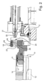
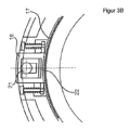
- 鋼成形材を矯正するための矯正機(1)、特に、二重に支持された矯正軸(4)を備えた矯正機(1)であって、前記矯正軸にはそれぞれ、矯正すべき成形材の成形チャンバ(7)内に係合するための矯正ロールセットにおける矯正ロール(5)が配置されており、少なくとも1つの矯正軸(4)の少なくとも1つの矯正ロールセットの前記矯正ロール(5)の軸方向の間隔は、前記成形材のチャンバ寸法に相応に調節可能であって、矯正ロールセットの軸方向で変位可能な少なくとも1つの矯正ロール(5)は、調節可能な軸受ブシュ(11)上に配置されており、前記軸受ブシュは、前記矯正軸(4)の駆動装置による前記矯正軸(4)の回動により前記軸受ブシュ(11)の調節を行うことができる調節ナット(15)に係合し、前記調節ナット(15)は、第1のロック位置で相対回動不能に前記矯正軸(4)に結合されていて、前記矯正軸(4)に関してロック解除された第2の位置では回動不能に固定されており、これにより、前記矯正軸(4)の回転により、前記調節可能な軸受ブシュ(11)の軸方向の変位が行われ、前記矯正機は、前記矯正軸(4)の所定の角度位置において前記調節ナット(15)をロックおよびロック解除するための手段ならびに好ましくはロック解除ピン(21)の形態の少なくとも1つのロック解除機構を有しており、前記ロック解除機構は、前記矯正軸(4)の所定の角度位置で、前記調節ナット(15)のロック機構に係合し、前記調節ナット(15)を前記矯正軸(4)に関してロック解除し、前記調節ナット(15)を回動不能に固定し、前記ロック機構は、ばね負荷されて前記第1のロック位置に保持される少なくとも1つのロックエレメント(16)を有している、矯正機において、
前記ロックエレメント(16)は前記ロック位置で、前記矯正軸(4)の組付けブシュ(9)に形状接続的に係合し、前記ロック解除機構はロック解除ピン(21)として形成されており、待機位置から、走出された係合位置へと軸方向で摺動可能であって、前記係合位置では、前記ロック解除機構は、前記調節ナット(15)の捕捉開口(20)内に進入することを特徴とする、矯正機(1)。 - 前記ロック解除機構は、前記調節ナット(15)のロック解除位置を検出するための手段を有している、請求項1記載の矯正機(1)。
- 前記ロック機構は、ばね負荷されて前記第1のロック位置に保持される少なくとも1つのロックエレメント(16)を有している、請求項1記載の矯正機(1)。
- 前記ロック解除機構は、傾斜したまたは円錐状の係合面を有しており、前記係合面は、前記ロックエレメント(16)の相補的に形成されたガイド面と協働して前記ロックエレメント(16)をロック解除位置に持ち上げる、請求項1記載の矯正機(1)。
- 前記ロック解除機構は、前記調節ナット(15)の前記捕捉開口(20)を検出可能な少なくとも1つのセンサ(25)を有している、請求項1記載の矯正機(1)。
- 少なくとも1つの矯正ロールセットのチャンバ寸法の調節のための閉ループ制御装置および/または開ループ制御装置と協働する少なくとも1つの成形材測定機器を有している、請求項1記載の矯正機(1)。
- 請求項1から6までのいずれか1項の特徴を備えた矯正機(1)を使用して鋼成形材を矯正するための方法であって、以下の方法ステップ、すなわち、
a)前記鋼成形材の実際輪郭を、少なくとも1つの矯正ロールセットのチャンバ寸法の調節のための閉ループ制御装置および開ループ制御装置と協働し、評価ユニットを介して、矯正ロールのためのロール調整部に接続されている測定装置によって、矯正機の手前および/または後方で検出するステップと、
b)前記実際輪郭を所与の目標輪郭と比較するステップと、
c)前記実際輪郭と前記目標輪郭との間に偏差が検知された場合に、矯正工程を停止するステップと、
d)少なくとも1つの矯正軸(4)の少なくとも1つの矯正ロールセットの少なくとも1つの矯正ロール装置のチャンバ寸法を、前記矯正軸(4)を所与の角度値だけ回動させることにより調節するステップと、
を含む方法。 - 前記チャンバ寸法を調節するステップを、少なくとも1つの矯正軸(4)の主駆動装置を介して行い、前記主駆動装置は、インクリメンタルエンコーダに基づいて、前記矯正軸(4)を、所望のチャンバ寸法に応じて与えられた目標角度だけ回動させる、請求項7記載の方法。
Applications Claiming Priority (3)
| Application Number | Priority Date | Filing Date | Title |
|---|---|---|---|
| DE102022200717.4 | 2022-01-24 | ||
| DE102022200717 | 2022-01-24 | ||
| PCT/EP2022/087908 WO2023138888A1 (de) | 2022-01-24 | 2022-12-27 | Richtmaschine sowie verfahren zum richten eines stahlprofils |
Publications (2)
| Publication Number | Publication Date |
|---|---|
| JP2024543852A JP2024543852A (ja) | 2024-11-26 |
| JP7635467B2 true JP7635467B2 (ja) | 2025-02-25 |
Family
ID=84981870
Family Applications (1)
| Application Number | Title | Priority Date | Filing Date |
|---|---|---|---|
| JP2024529284A Active JP7635467B2 (ja) | 2022-01-24 | 2022-12-27 | 鋼成形材を矯正するための矯正機ならびに方法 |
Country Status (3)
| Country | Link |
|---|---|
| EP (1) | EP4469223B1 (ja) |
| JP (1) | JP7635467B2 (ja) |
| WO (1) | WO2023138888A1 (ja) |
Families Citing this family (1)
| Publication number | Priority date | Publication date | Assignee | Title |
|---|---|---|---|---|
| WO2025158474A1 (en) * | 2024-01-23 | 2025-07-31 | Danieli & C. Officine Meccaniche S.P.A. | Device and method for adjusting the distance between straightening rings of a straightening apparatus |
Citations (2)
| Publication number | Priority date | Publication date | Assignee | Title |
|---|---|---|---|---|
| EP0769335A1 (en) | 1995-09-29 | 1997-04-23 | Kawasaki Steel Corporation | Apparatus for reforming rollers for shaping rolled steel |
| JP2000351016A (ja) | 1999-06-09 | 2000-12-19 | Hitachi Zosen Corp | ロール幅調整装置 |
Family Cites Families (6)
| Publication number | Priority date | Publication date | Assignee | Title |
|---|---|---|---|---|
| US5109687A (en) * | 1991-07-08 | 1992-05-05 | Nippon Steel Corporation | Device for adjustment of barrel width of roll type straightener |
| DE4323468A1 (de) | 1993-07-14 | 1995-01-19 | Schloemann Siemag Ag | Richtmaschine für gewalzte Träger, insbesondere H-Träger |
| DE4324416A1 (de) | 1993-07-21 | 1995-01-26 | Schloemann Siemag Ag | Richtmaschine für gewalzte Träger, insbesondere Hyper-Beams |
| JP3429636B2 (ja) * | 1997-01-10 | 2003-07-22 | 日立造船株式会社 | ロール幅調整装置 |
| JP3755230B2 (ja) * | 1997-04-15 | 2006-03-15 | Jfeスチール株式会社 | H形鋼ローラ矯正機のローラ幅変更装置及び変更方法 |
| DE19819063A1 (de) | 1998-04-29 | 1999-11-04 | Schloemann Siemag Ag | Richtmaschine für gewalzte Träger |
-
2022
- 2022-12-27 JP JP2024529284A patent/JP7635467B2/ja active Active
- 2022-12-27 WO PCT/EP2022/087908 patent/WO2023138888A1/de not_active Ceased
- 2022-12-27 EP EP22844498.0A patent/EP4469223B1/de active Active
Patent Citations (2)
| Publication number | Priority date | Publication date | Assignee | Title |
|---|---|---|---|---|
| EP0769335A1 (en) | 1995-09-29 | 1997-04-23 | Kawasaki Steel Corporation | Apparatus for reforming rollers for shaping rolled steel |
| JP2000351016A (ja) | 1999-06-09 | 2000-12-19 | Hitachi Zosen Corp | ロール幅調整装置 |
Also Published As
| Publication number | Publication date |
|---|---|
| EP4469223B1 (de) | 2025-04-02 |
| JP2024543852A (ja) | 2024-11-26 |
| EP4469223A1 (de) | 2024-12-04 |
| WO2023138888A1 (de) | 2023-07-27 |
Similar Documents
| Publication | Publication Date | Title |
|---|---|---|
| JP7635467B2 (ja) | 鋼成形材を矯正するための矯正機ならびに方法 | |
| CN203599285U (zh) | 一种变辊距矫直机 | |
| US6834825B2 (en) | Strip winding and unwinding device with automatic centering | |
| US3985013A (en) | Apparatus for rapidly changing straightening rollers of a roller straightening machine | |
| US5660068A (en) | Roll type processing facility and roll width adjusting device therefor | |
| WO2016124168A1 (de) | VORRICHTUNG UND VERFAHREN ZUM MOBILEN RÜHRREIBSCHWEIßEN VON ZWEI ROHRARTIGEN STRUKTUREN | |
| KR101075336B1 (ko) | 원형관의 교정장치 및 방법 | |
| JPS6360010A (ja) | 形鋼製造用ロールスタンドのロール軸方向位置調整装置 | |
| EP3582908B1 (en) | Apparatus and method to guide metal products | |
| CA2271115A1 (en) | Flow forming method and device | |
| CN208960626U (zh) | 万能轧机传动侧立辊横梁升降装置 | |
| CN114855768A (zh) | 一种钢管柱定位施工方法 | |
| EP0693329A2 (en) | Roll type processing facility and roll width adjusting device therefor | |
| CA2729842A1 (en) | Roller device with adjuster device | |
| CN112318450A (zh) | 一种宽厚板矫直机高效换辊系统 | |
| US4248074A (en) | Axial roll adjustment for a rolling mill | |
| JPH09150220A (ja) | 形鋼用ローラ矯正機の幅可変装置 | |
| CN213562389U (zh) | 一种宽厚板矫直机高效换辊系统 | |
| JP3289009B2 (ja) | 圧延機のロールカリバーの位置決め装置 | |
| US3563077A (en) | Rolling mill for rolling bushes and the like | |
| KR101151248B1 (ko) | 롤 스탠드 | |
| WO2025158474A1 (en) | Device and method for adjusting the distance between straightening rings of a straightening apparatus | |
| JP2651939B2 (ja) | ロールスタンドのロールの軸線方向案内装置 | |
| RU2075360C1 (ru) | Устройство для волочения | |
| JPS5978723A (ja) | 熱延鋼板巻取機におけるマンドレルとエプロンガイドとのギヤツプ調整装置 |
Legal Events
| Date | Code | Title | Description |
|---|---|---|---|
| A521 | Request for written amendment filed |
Free format text: JAPANESE INTERMEDIATE CODE: A523 Effective date: 20240515 |
|
| A529 | Written submission of copy of amendment under article 34 pct |
Free format text: JAPANESE INTERMEDIATE CODE: A529 Effective date: 20240515 |
|
| A621 | Written request for application examination |
Free format text: JAPANESE INTERMEDIATE CODE: A621 Effective date: 20240515 |
|
| TRDD | Decision of grant or rejection written | ||
| A01 | Written decision to grant a patent or to grant a registration (utility model) |
Free format text: JAPANESE INTERMEDIATE CODE: A01 Effective date: 20250114 |
|
| A61 | First payment of annual fees (during grant procedure) |
Free format text: JAPANESE INTERMEDIATE CODE: A61 Effective date: 20250212 |
|
| R150 | Certificate of patent or registration of utility model |
Ref document number: 7635467 Country of ref document: JP Free format text: JAPANESE INTERMEDIATE CODE: R150 |