JP7635467B2 - Machine and method for straightening steel sections - Google Patents
Machine and method for straightening steel sections Download PDFInfo
- Publication number
- JP7635467B2 JP7635467B2 JP2024529284A JP2024529284A JP7635467B2 JP 7635467 B2 JP7635467 B2 JP 7635467B2 JP 2024529284 A JP2024529284 A JP 2024529284A JP 2024529284 A JP2024529284 A JP 2024529284A JP 7635467 B2 JP7635467 B2 JP 7635467B2
- Authority
- JP
- Japan
- Prior art keywords
- straightening
- shaft
- adjusting nut
- machine
- locking
- Prior art date
- Legal status (The legal status is an assumption and is not a legal conclusion. Google has not performed a legal analysis and makes no representation as to the accuracy of the status listed.)
- Active
Links
- 238000000034 method Methods 0.000 title claims description 13
- 229910000831 Steel Inorganic materials 0.000 title claims description 8
- 239000010959 steel Substances 0.000 title claims description 8
- 238000006073 displacement reaction Methods 0.000 claims description 2
- 238000011156 evaluation Methods 0.000 claims description 2
- 230000000295 complement effect Effects 0.000 description 2
- 230000001939 inductive effect Effects 0.000 description 2
- 230000013011 mating Effects 0.000 description 2
- 238000005452 bending Methods 0.000 description 1
- 230000001419 dependent effect Effects 0.000 description 1
- 238000001514 detection method Methods 0.000 description 1
- 238000009434 installation Methods 0.000 description 1
Images


Classifications
-
- B—PERFORMING OPERATIONS; TRANSPORTING
- B21—MECHANICAL METAL-WORKING WITHOUT ESSENTIALLY REMOVING MATERIAL; PUNCHING METAL
- B21D—WORKING OR PROCESSING OF SHEET METAL OR METAL TUBES, RODS OR PROFILES WITHOUT ESSENTIALLY REMOVING MATERIAL; PUNCHING METAL
- B21D3/00—Straightening or restoring form of metal rods, metal tubes, metal profiles, or specific articles made therefrom, whether or not in combination with sheet metal parts
- B21D3/02—Straightening or restoring form of metal rods, metal tubes, metal profiles, or specific articles made therefrom, whether or not in combination with sheet metal parts by rollers
- B21D3/05—Straightening or restoring form of metal rods, metal tubes, metal profiles, or specific articles made therefrom, whether or not in combination with sheet metal parts by rollers arranged on axes rectangular to the path of the work
Landscapes
- Engineering & Computer Science (AREA)
- Mechanical Engineering (AREA)
- Straightening Metal Sheet-Like Bodies (AREA)
- Wire Processing (AREA)
Description
本発明は、鋼成形材を矯正するための矯正機、特に、二重に支持された矯正軸を備えた矯正機であって、矯正軸にはそれぞれ、矯正すべき成形材の成形チャンバ内に係合するための矯正ロールセットにおける矯正ロールが配置されている矯正機に関する。 The present invention relates to a straightening machine for straightening steel profiles, in particular a straightening machine with doubly supported straightening shafts, on each of which a straightening roll of a straightening roll set is arranged for engagement in the forming chamber of the profile to be straightened.
本発明は特に、圧延された支持体を矯正するための、特にいわゆるH形鋼を矯正するための矯正機に関する。 The present invention relates in particular to a straightening machine for straightening rolled supports, in particular so-called H-beams.
調節可能なチャンバ寸法を有する矯正機は、従来技術において基本的に公知である。したがって、独国特許出願公開第4323468号明細書からは、圧延された支持体のための矯正機が公知であり、この矯正機では、支持体の両フランジに内側から当て付けられる、矯正軸によって支持された矯正板のうちの少なくとも1つの矯正板が軸方向で調節可能である。この矯正機では、矯正板の外寸またはチャンバ寸法を簡単な形式で迅速に変更することができる。独国特許出願公開第4323468号明細書による解決手段では、このために、矯正板摺動のためにウォーム歯車駆動装置を使用することが提案されており、この場合、矯正板は、ウォーム歯車駆動装置が作用する環状スリーブまたは摺動ブシュと固く結合されている。独国特許出願公開第4323468号明細書に記載の矯正機は、矯正軸が片側でしか支持されていないいわゆるカンチレバー矯正機である。このような機械では、矯正板は、比較的小さなまたは比較的大きな相互間隔に調節すべき場合に、まずは、矯正軸の緊締ヘッドによって矯正軸の片側に緊締された矯正板を解除し、ウォームひいてはウォーム歯車を回転させる必要がある。この場合、所属の矯正板を備えた環状スリーブは、例えばゲージまたはノギスによって調整することができる所望の間隔となるまで摺動される。その後、緊締ヘッドによって、矯正板または矯正ロールの必要な緊締が再び形成される。 Straighteners with adjustable chamber dimensions are basically known in the prior art. Thus, from DE 43 23 468 A1, a straightener for rolled supports is known, in which at least one of the straightener plates supported by a straightener shaft, which is applied from the inside against both flanges of the support, is axially adjustable. In this straightener, the outer dimensions or chamber dimensions of the straightener plate can be changed quickly in a simple manner. In the solution according to DE 43 23 468 A1, it is proposed to use a worm gear drive for the straightener plate sliding, in which the straightener plate is rigidly connected to an annular sleeve or a sliding bush on which the worm gear drive acts. The straightener according to DE 43 23 468 A1 is a so-called cantilever straightener, in which the straightener shaft is supported only on one side. In such machines, if the straightening plates are to be adjusted to a smaller or larger mutual distance, it is first necessary to release the straightening plates clamped to one side of the straightening shaft by the clamping head of the straightening shaft and rotate the worm and thus the worm gear. In this case, the annular sleeve with the associated straightening plates is slid to the desired distance, which can be adjusted, for example, by means of a gauge or caliper. The required clamping of the straightening plates or straightening rolls is then established again by the clamping head.
調節可能なチャンバ寸法を有する矯正機の別の態様は、例えば独国特許出願公開第4324416号明細書により公知である。同じく片側で支持された矯正軸を含むこの矯正機では、矯正板間に、内部で周囲にわたって分配された複数の液圧シリンダのための支持リングが配置されており、その作動ピストンは矯正板に結合されている。 Another embodiment of a straightener with adjustable chamber dimensions is known, for example, from DE 43 24 416 A1. In this straightener, which also includes a straightening shaft supported on one side, a support ring is arranged between the straightening plates for a number of hydraulic cylinders distributed internally around the circumference, the working pistons of which are connected to the straightening plates.
欧州特許第0953385号明細書から公知の、圧延された支持体のための矯正機では、矯正軸により支持された矯正板が軸方向で調節可能であり、一方の矯正板は、組付けブッシュを介して矯正軸に堅固に結合されており、他方で第2の調節可能な矯正板は、その調節寸法に相応に逆側で、組付けブッシュ上に調節可能に配置された摺動ブシュに載置されている。ピストン・シリンダユニットが、矯正軸の中央に配置されており、摺動ブシュ単独の位置決めまたはチャンバ寸法調節のためにも、摺動ブシュと共に組付けブシュを引き抜くためにも設けられている。 In a straightening machine for rolled supports, known from EP 0 953 385, the straightening plates supported by the straightening shaft are axially adjustable, one straightening plate is rigidly connected to the straightening shaft via an assembly bush, while the second adjustable straightening plate is mounted on a sliding bush adjustably arranged on the assembly bush on the opposite side according to its adjustment dimension. A piston-cylinder unit is arranged in the center of the straightening shaft and is provided both for positioning the sliding bush alone or for adjusting the chamber dimension, and for withdrawing the assembly bush together with the sliding bush.
矯正機のチャンバ寸法を調節するための従来技術において公知の態様は、両側で支持された矯正軸に簡単に転用することはできない。何故ならば、矯正機の構成部分へのアクセスが、カンチレバー矯正機の場合と同程度には得られないからである。このような機械では、組み付けられたローラ間隔により、寸法または形状が許容誤差範囲内にない場合には、状況によっては、新しい矯正ロールセットの組付けが必要となり、これは比較的手間がかかる。
欧州特許出願公開第0769335号明細書により、請求項1の上位概念に記載の矯正機が公知である。さらなる従来技術は、米国特許第5109687号明細書、特開平10-286623号明細書ならびに特開平10-192925号明細書により公知である。
The methods known in the prior art for adjusting the chamber dimensions of the straightener cannot be easily transferred to a double-supported straightening shaft, since access to the components of the straightener is not as available as in the case of cantilever straighteners, and in such machines, the installed roller spacing may require the installation of a new set of straightening rolls if the dimensions or shape are not within the tolerances, which is relatively time-consuming.
From EP 0 769 335 A1 a straightener is known which is described in the preamble of claim 1. Further prior art is known from US Pat. No. 5,109,687, JP 10-286623 A1 and JP 10-192925 A1.
そこで、本発明の根底にある課題は、比較的簡単にチャンバ寸法調節または個々の矯正板の相互間隔の調節が可能であるような冒頭で述べた形式の両側で支持される矯正軸を備えた矯正機を提供することである。 The object of the present invention is therefore to provide a straightening machine with a straightening shaft supported on both sides of the type mentioned at the beginning, which allows relatively simple adjustment of the chamber size or the spacing between the individual straightening plates.
この課題は、請求項1の特徴によって解決される。本発明の有利な構成は、従属請求項に記載されている。 This problem is solved by the features of claim 1. Advantageous configurations of the invention are described in the dependent claims.
この課題はさらに、請求項7の特徴を備えた方法を提供することによって解決される。 The problem is further solved by providing a method with the features of claim 7 .
本発明の1つの観点は、鋼成形材を矯正するための矯正機、特に、二重に支持された矯正軸を備えた矯正機であって、矯正軸にはそれぞれ、矯正すべき成形材の成形チャンバ内に係合するための矯正ロールセットをなす矯正ロールが配置されており、少なくとも1つの矯正軸の少なくとも1つの矯正ロールセットの矯正ロールの軸方向の間隔は、成形材のチャンバ寸法に相応に調節可能であって、矯正ロールセットの軸方向で変位可能な少なくとも1つの矯正ロールは、調節可能な軸受ブシュ上に配置されており、軸受ブシュは、矯正軸の駆動装置による矯正軸の回動により軸受ブシュの調節を行うことができる調節ナットに係合する、矯正機に関する。 One aspect of the invention relates to a straightening machine for straightening steel profiles, in particular a straightening machine with doubly supported straightening shafts, on each of which straightening rolls of a straightening roll set are arranged for engagement in the forming chamber of the profile to be straightened, the axial spacing of the straightening rolls of at least one straightening roll set of at least one straightening shaft is adjustable corresponding to the chamber dimensions of the profile, and at least one axially displaceable straightening roll of the straightening roll set is arranged on an adjustable bearing bush, which engages with an adjustment nut that allows adjustment of the bearing bush by rotation of the straightening shaft by the drive of the straightening shaft.
本発明の意味では、軸方向とは、矯正軸の長手方向軸線に対して平行または回転軸線に対して平行であることを意味する。 In the sense of the present invention, axial direction means parallel to the longitudinal axis of the straightening shaft or parallel to the axis of rotation.
本発明の重要な観点は、矯正ロールまたは矯正板がそれぞれ好ましくは対になって、一方の矯正ロールは定置の軸受ブシュ上に配置されており、所属の他方の矯正ロールは、定置の軸受ブシュに対して調節可能な軸受ブシュ(摺動ブシュ)上に配置されるように互いに配置されていること、およびこれらの軸受ブシュの相互間隔が矯正機の主駆動装置または当該矯正軸の駆動装置によって調節可能であることである。すなわち、本発明によれば、一方の矯正ロールのアセンブリは、矯正機の主駆動装置によって矯正軸に沿って軸方向で調節可能な摺動ブシュ上に設けられている。 An important aspect of the present invention is that the straightening rolls or straightening plates are preferably arranged in pairs, with one straightening roll on a fixed bearing bush and the other associated straightening roll on a bearing bush (sliding bush) that is adjustable relative to the fixed bearing bush, and the mutual spacing of these bearing bushes is adjustable by the main drive of the straightening machine or the drive of the straightening shaft. That is, according to the present invention, the assembly of one straightening roll is mounted on a sliding bush that is axially adjustable along the straightening shaft by the main drive of the straightening machine.
本発明による矯正機は、ダブルT成形材またはH成形材を含む圧延された支持体を矯正するために形成されている。しかしながら、当業者には、この矯正機は、互いに所定の間隔を置いて配置された成形材脚を有するU成形材のような成形材を矯正するためにも設けることができることが認知可能である。 The straightening machine according to the invention is designed for straightening rolled supports including double T-shaped or H-shaped sections. However, it is recognizable to those skilled in the art that the straightening machine can also be provided for straightening profiles such as U-shaped sections having profile legs spaced apart from one another.
本発明による矯正機では、調節ナットは、第1のロック位置で相対回動不能に矯正軸に結合されていて、矯正軸に関してロック解除された第2の位置では回動不能に固定されており、これにより、矯正軸の回転により、調節可能な軸受ブシュの軸方向の変位が行われることが想定されている。 In the straightening machine according to the invention, it is envisaged that the adjusting nut is connected to the straightening shaft in a first locked position so as not to rotate relative to the straightening shaft and in a second unlocked position so as to be fixed so as not to rotate relative to the straightening shaft, whereby rotation of the straightening shaft results in an axial displacement of the adjustable bearing bush.
調節可能な軸受ブシュは、例えば、嵌合キーによって、組付けブシュに相対回動不能に結合させることができ、この組付けブシュも相対回動不能に矯正軸に結合されている。 The adjustable bearing bushing can be non-rotatably connected to the mounting bushing, for example by means of a mating key, and the mounting bushing is also non-rotatably connected to the straightening shaft.
本発明によれば、本発明による矯正機は、矯正軸の所定の角度位置において調節ナットをロックおよびロック解除するための手段を有している。 According to the invention , the straightening machine according to the invention comprises means for locking and unlocking the adjusting nut in a given angular position of the straightening shaft.
このために、本発明による矯正機は、好ましくはロック解除ピンまたはロック解除ボルトの形態で形成されている少なくとも1つのロック解除機構を有しており、このロック解除機構は、矯正軸の所定の角度位置で、調節ナットのロック機構に係合し、調節ナットを矯正軸に関してロック解除し、調節ナットを回動不能に固定する。ロック解除機構はこのために、矯正機のスタンドに、またはスタンドに支持された組付け部材に定置に配置されていてよい。 For this purpose, the straightening machine according to the invention has at least one unlocking mechanism, preferably in the form of an unlocking pin or an unlocking bolt, which in a predefined angular position of the straightening shaft engages with the locking mechanism of the adjusting nut, unlocks the adjusting nut with respect to the straightening shaft and fixes the adjusting nut against rotation. The unlocking mechanism can be arranged for this purpose in a fixed manner on the stand of the straightening machine or on an assembly part supported on the stand.
ロック解除機構が、調節ナットのロック解除位置を検出または検知する手段を有しているならば特に有利である。 It is particularly advantageous if the unlocking mechanism has means for detecting or sensing the unlocked position of the adjusting nut.
本発明によれば、ロック機構は、ばね負荷されて第1のロック位置に保持される少なくとも1つのロックエレメントを有している。ロックエレメントはロック位置で、矯正軸の組付けブシュに形状接続的に係合することができる。このために、例えば組付けブシュは、ロック位置でロックエレメントの歯列を備えた対応部材が係合する、歯列を備えたカラーまたは環状歯列を有していてよい。 According to the invention , the locking mechanism has at least one locking element which is spring-loaded and held in a first locking position, in which the locking element can form-lockingly engage with a mounting bush of the straightening shaft, for example, the mounting bush can have a toothed collar or an annular toothing, which engages in the locking position with a corresponding toothed element of the locking element.
さらに、ロック解除機構もしくはロック解除ピンまたはロック解除ボルトは、走出された係合位置へと軸方向で摺動可能であり、この位置で調節ナットの捕捉開口内に進入する。ロック解除機構は例えば、液圧式または空圧式に操作可能なロック解除ピンとして形成されていてよい。ロック解除ピンは、例えば、ピストン・シリンダ装置のピストンとして形成されていてもよいし、または矯正機のスタンドまたは組付け部材に取り付けられているピストン・シリンダ装置によって操作可能であってもよい。 Furthermore , the unlocking mechanism or unlocking pin or unlocking bolt can be axially slidable to a deployed engagement position, in which it enters into a catch opening in the adjusting nut. The unlocking mechanism can be formed, for example, as a hydraulically or pneumatically operable unlocking pin. The unlocking pin can be formed, for example, as a piston of a piston-cylinder device or can be operable by a piston-cylinder device that is attached to a stand or mounting part of the straightening machine.
矯正軸は軸方向で変位可能に形成されていてよく、これにより、調節ナットは矯正軸と共にまずは、ロック解除機構と協働することができる待機位置へと変位可能である。 The straightening shaft may be configured to be displaceable in the axial direction, so that the adjustment nut together with the straightening shaft can first be displaced into a standby position in which it can cooperate with the unlocking mechanism.
好ましくは、ロック解除機構は、傾斜したまたは円錐状の係合面を有しており、この係合面は、ロックエレメントの相補的に形成されたガイド面と協働してロックエレメントをばね力に抗してロック解除位置に持ち上げ、この位置では、調節ナットと組付けブシュ、またはこの組付けブシュに相対回動不能に結合された矯正軸との間の相対回動不能な結合が解消される。矯正機の作動時には、調節ナットは、この部分の慣性質量または回転運動によって生じる可能性のある回転運動に抗して固定されている。 Preferably, the unlocking mechanism has an inclined or conical engagement surface which cooperates with a complementary guide surface of the locking element to lift the locking element against the spring force to an unlocked position, in which the non-rotatable connection between the adjusting nut and the assembly bush or the straightening shaft non-rotatably connected to the assembly bush is eliminated. During operation of the straightening machine, the adjusting nut is fixed against possible rotational movements caused by the inertial mass or rotational movements of this part.
ロック機構が、調節ナットの捕捉開口を検出可能な少なくとも1つのセンサを有していると、特に有利である。このようなセンサは、最も単純には、調節機構のガイド端部が調節ナットの捕捉開口に整合して位置調整されると、ロック解除信号を生成する誘導型センサまたは磁石センサであってよい。この場合、ロック機構が、調節ナットの捕捉開口内に係合すると、これにより、ロックエレメントはロック解除位置へと持ち上げられ、調節ナットはロック解除機構によって回動不能に保持される。 It is particularly advantageous if the locking mechanism has at least one sensor capable of detecting the catching opening of the adjusting nut. Such a sensor can most simply be an inductive or magnetic sensor that generates an unlocking signal when the guide end of the adjusting mechanism is aligned and aligned with the catching opening of the adjusting nut. In this case, when the locking mechanism engages in the catching opening of the adjusting nut, the locking element is raised to the unlocked position and the adjusting nut is held non-rotatably by the unlocking mechanism.
本発明による矯正機の特に好適な態様は、少なくとも1つの矯正ロールセットのチャンバ寸法の調節のための閉ループおよび/または開ループ制御装置と協働する少なくとも1つの成形材測定機器の点で優れている。成形材測定機器としては、例えば、支持体または成形材の搬送方向で下流に配置された、例えばH型の支持体成形材の成形材形状を定義するための測定装置が設けられていてよく、この測定装置は、評価ユニットを介して、矯正ロールのためのロール調整部に接続されている。測定装置は、例えば、修正すべきH型の支持体成形材のジオメトリを検出し、少なくとも1つの矯正軸の矯正ロールの相応のロール調整または調節を行わせるレーザー装置を備えていてよい。 A particularly preferred embodiment of the straightening machine according to the invention is distinguished by at least one profile measuring device which cooperates with a closed-loop and/or open-loop control device for adjusting the chamber dimensions of at least one straightening roll set. The profile measuring device may, for example, be a measuring device arranged downstream in the conveying direction of the support or the profile for defining the profile shape of, for example, an H-shaped support profile, which is connected via an evaluation unit to a roll adjustment for the straightening rolls. The measuring device may, for example, be equipped with a laser device which detects the geometry of the H-shaped support profile to be corrected and causes a corresponding roll adjustment or adjustment of the straightening rolls of at least one straightening axis.
本発明による矯正機は、好ましくは、上側ロール対と下側ロール対とを備えた水平型矯正機として形成されている。本発明によれば、上側ロール対および/または少なくとも1つの矯正軸の上側ロール対における矯正ロールの調節可能性が想定されていてよい。 The straightening machine according to the invention is preferably configured as a horizontal straightening machine with an upper roll pair and a lower roll pair. According to the invention, adjustability of the straightening rolls in the upper roll pair and/or the upper roll pair of at least one straightening shaft may be envisaged.
本発明のさらなる観点は、上述した1つ以上の特徴を備えた矯正機を使用して鋼成形材を矯正するための方法であって、以下の方法ステップ、すなわち、
a)鋼成形材の実際輪郭を、矯正機の手前および/または後方で検出するステップと、
b)実際輪郭を所与の目標輪郭と比較するステップと、
c)矯正工程を停止するステップと、
d)少なくとも1つの矯正軸の少なくとも1つの矯正ロールセットの少なくとも1つの矯正ロール装置のチャンバ寸法を、矯正軸を所与の角度値だけ回動させることにより調節するステップと、
を含む方法に関する。
A further aspect of the present invention is a method for straightening steel sections using a straightening machine having one or more of the features described above, comprising the following method steps:
a) detecting the actual contour of the steel profile before and/or after the straightening machine;
b) comparing the actual contour with a given target contour;
c) stopping the straightening process;
d) adjusting the chamber size of at least one straightening roll device of at least one straightening roll set of at least one straightening shaft by rotating the straightening shaft by a given angle value;
The present invention relates to a method comprising the steps of:
好適には、チャンバ寸法を調節するステップを、少なくとも1つの矯正軸の主駆動装置を介して行い、主駆動装置は、インクリメンタルエンコーダに基づいて、矯正軸を、所望のチャンバ寸法に応じて与えられた目標角度だけ回動させる。 Preferably, the step of adjusting the chamber size is performed via a main drive of at least one straightening shaft, which rotates the straightening shaft by a given target angle based on an incremental encoder according to the desired chamber size.
以下に、本発明を図示した実施例に基づき説明する。 The present invention will be explained below based on the illustrated embodiment.
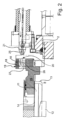
図面に断面図で示された矯正機1は、組付け部材2を介してスタンド3内に支持された複数の矯正軸4を有しており、これらの矯正軸には、矯正ロール5がそれぞれ矯正ロールセットとして対をなして配置されている。矯正機1は、上側および下側の矯正ロール対を有しており、これらの矯正ロール対は、圧延された支持体6に関して曲げ三角形を形成するように互いに配置されている。 The straightening machine 1 shown in cross section in the drawing has a number of straightening shafts 4 supported in a stand 3 via mounting members 2, on which straightening rolls 5 are arranged in pairs as straightening roll sets. The straightening machine 1 has upper and lower straightening roll pairs, which are arranged relative to one another so as to form a bending triangle with respect to the rolled support 6.
図面には、1つの上側の矯正軸4または上側の矯正ロールセットのみが示されている。矯正軸4は、軸方向で互いに緊締されている複数の部分を有しており、これについては簡略化のために以下では詳しくは説明しない。下側の矯正軸4は、簡略化のために図示されていない。 In the figures, only one upper straightening shaft 4 or an upper straightening roll set is shown. The straightening shaft 4 has several parts which are axially clamped together, which for the sake of simplicity will not be described in detail below . The lower straightening shaft 4 is not shown for the sake of simplicity.
矯正軸4は、それぞれ端部側で組付け部材2において水平に支持されており、図面において矯正軸4の左側が駆動側であり、右側がいわゆる操作側である。矯正軸4の駆動装置または主駆動装置は、簡略化のために図示されていない。駆動装置の軸ピンのみが概略的に示されている。 The straightening shaft 4 is supported horizontally at each end in the mounting member 2, with the left side of the straightening shaft 4 in the drawing being the drive side and the right side being the so-called operating side. The drive or main drive of the straightening shaft 4 is not shown for the sake of simplicity. Only the axle pins of the drive are shown diagrammatically.
符号5で示された矯正ロールは、支持体6の成形チャンバ7内に係合し、支持体6のフランジ8に内側から当て付けられている。成形チャンバ7の内側のフランジ8間の間隔は、チャンバ寸法と呼ばれる。図面では、異なるチャンバ寸法を有する2つの異なる支持体6が概略的に示されている。 The straightening rolls, designated by the reference number 5, engage in the forming chamber 7 of the support 6 and are applied from the inside to the flanges 8 of the support 6. The distance between the flanges 8 inside the forming chamber 7 is called the chamber dimension. In the drawing, two different supports 6 with different chamber dimensions are shown diagrammatically.
矯正軸4は、軸方向で緊締された状態で、この矯正軸上に配置された組付けブシュ9に、この組付けブシュを連行するように摩擦接続を介して結合されている。各矯正ロール5は、相対回動不能に軸受ブシュ10,11に結合されており、図面において左側の軸受ブシュ10は定置の軸受ブシュとして形成されており、図面において右側の軸受ブシュ11は、組付けブシュ9に対して軸方向で調節可能である。組付けブシュ9も、矯正軸4に相対回動不能に結合されている。調節可能な軸受ブシュ11が、組付けブシュ9に関しておよび矯正軸4に関して回動不能であることは、嵌合キー12によって保証される。
The straightening shaft 4 is connected in an axially tightened manner to an assembly bush 9 arranged on the straightening shaft via a frictional connection so as to entrain the assembly bush. Each straightening roll 5 is connected to a bearing
特に図2の拡大図によって明らかであるように、調節可能な軸受ブシュ11には、組付けブシュ9のカラー13に面した側で雄ねじ山14が設けられており、この雄ねじ山は、調節ナット15の雌ねじ山に噛み合う。
As can be seen particularly from the enlarged view of FIG. 2, the
調節ナット15は、ロック状態で、組付けブシュ9に相対回動不能に結合されており、すなわち調節ナットは、組付けブシュ9の周面における環状歯列17に係合するロックエレメント16を介して形状接続的に保持される。
In the locked state, the adjusting nut 15 is connected to the mounting bush 9 in a non-rotatable manner, i.e. the adjusting nut is held in a form-locking manner via a locking
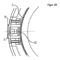
ロックエレメント16は、ロック位置(図3B参照)でばね負荷されて保持されており、調節ナット15の周囲に半径方向で延在するガイド通路18の内側に摺動可能に支持されている。
The locking
ロックエレメント16、および調節ナット15の、ガイド通路18を取り囲むカラー19の両方に、捕捉開口20が貫通しており、この捕捉開口内には、矯正機1の組付け部材2に保持されたロック解除ピン21が進入することができる。ロックピン21は、第1のピストン・シリンダ装置23を介して出し入れ可能である。第1のピストン・シリンダ装置23は、図1に示された装置においてスタンド3の組付け部材2に取り付けられている。第1のピストン・シリンダ装置は、スタンド3に取り付けられていてもよい。ロック解除ピン21のガイド端部には、例えば、調節ナット15内の捕捉開口20を検知するための誘導型センサとして形成されているセンサ25が装着されている。
Both the locking
特に図3Aおよび図3Bによりわかるように、ロック解除機構としてのロック解除ピン21の進入により、本発明によれば、ガイド通路18の内側でロックエレメント16が持ち上げられる。ロックエレメント16は、図3Bに示されたロック位置では、歯列プレート22で、組付けブシュ9の環状歯列17に係合しており、図3Bに示されたロック状態では、調節ナット15と組付けブシュ9との間の相対回動不能な結合を保証している。
As can be seen in particular in Figures 3A and 3B, the locking
図3Aに示されたロック解除状態は、ロック解除ピン21が完全に、捕捉開口20内におよびロックエレメント16の破断部27内に進入している状態を示している。ロックエレメント16における破断部27は、楔ガイドとして、ロック解除ピンの円錐状の先端と協働する内側のガイド傾斜部26を有している。
The unlocked state shown in FIG. 3A shows the unlocking
図3Aに示された位置では、ロック解除ピン21がロックエレメント16を持ち上げているので、歯列プレート22は環状歯列17から持ち上げられており、矯正軸4は組付けブシュ9と共に調節ナット15から分離されている。長手方向軸線を中心として矯正軸4が回転することにより、調節ナット15は軸方向で変位し、この場合、調節ナットは回動しないようにロック解除ピン21によって固定されている。
In the position shown in FIG. 3A, the unlocking
チャンバ寸法の調節または矯正ロール5の間の軸方向の間隔の調節は、まず、矯正機1を停止することにより行われる。矯正軸4は、第2のピストン・シリンダ装置24(図1)によって右に向かって変位し、これにより、ロック解除ピン21のセンサ25は、調節ナット15のカラー19に対して、センサ25の検出範囲内にカラー19が位置する程度に小さい間隔を置いて配置される。矯正軸4の異なる位置、ひいては調節ナット15の異なる位置は、図2に仮想線で示されている。次いで、センサ25が捕捉開口20を検出するまで、矯正軸4は長手方向軸線を中心としてゆっくりと回転される。捕捉開口20とロック解除ピン21とが互いに整列するように方向付けられると、ロック解除ピン21は走出位置(図2の矢印参照)にもたらされ、ロック解除ピンは、捕捉開口20内へ進入する際に、円錐状の係合面を形成する円錐状の先端で、ロックエレメント16の破断部27に相補的に形成されたガイド傾斜部26と協働して、この破断部27内への進入時にロックエレメント16を持ち上げ、これによりロックエレメント16の歯列プレート22は環状歯列17との係合を解除する。
The adjustment of the chamber size or the axial spacing between the straightening rolls 5 is first performed by stopping the straightening machine 1. The straightening shaft 4 is displaced to the right by the second piston-cylinder device 24 (FIG. 1), so that the
ロック解除ピン21は、この位置(図3A)では組付けブシュ9から分離されている調節ナット15を回動しないように固定する。矯正軸4の主駆動装置に組み込まれているインクリメンタルエンコーダによって、矯正軸4は、矯正ロール5の規定された所定の互いの調節距離に相当する目標角度に到るまで所定の角度値だけ回転される。
The unlocking
調節工程が終了すると、ロック解除ピン21は引き戻し位置にもたらされ、矯正軸4は、第2のピストン・シリンダ装置24によって再び左に向かって初期位置へと移動される。
When the adjustment process is completed, the unlocking
1 矯正機
2 組付け部材
3 スタンド
4 矯正軸
5 矯正ロール
6 支持体
7 成形チャンバ
8 フランジ
9 組付けブシュ
10 定置の軸受ブシュ
11 調節可能な軸受ブシュ
12 嵌合キー
13 組付けブシュのカラー
14 雄ねじ山
15 調節ナット
16 ロックエレメント
17 環状歯列
18 ガイド通路
19 調節ナットのカラー
20 捕捉開口
21 ロック解除ピン
22 歯列プレート
23 第1のピストン・シリンダ装置
24 第2のピストン・シリンダ装置
25 センサ
26 ガイド傾斜部
27 破断部
1 Straightening machine 2 Assembly part 3 Stand 4 Straightening shaft 5 Straightening roll 6 Support 7 Forming chamber 8 Flange 9
Claims (8)
前記ロックエレメント(16)は前記ロック位置で、前記矯正軸(4)の組付けブシュ(9)に形状接続的に係合し、前記ロック解除機構はロック解除ピン(21)として形成されており、待機位置から、走出された係合位置へと軸方向で摺動可能であって、前記係合位置では、前記ロック解除機構は、前記調節ナット(15)の捕捉開口(20)内に進入することを特徴とする、矯正機(1)。 The invention relates to a straightening machine (1) for straightening steel profiles, in particular a straightening machine (1) with doubly supported straightening shafts (4), on which are respectively arranged straightening rolls (5) of a straightening roll set for engaging in a forming chamber (7) of the profile to be straightened, the axial spacing of the straightening rolls (5) of at least one straightening roll set of at least one straightening shaft (4) being adjustable in accordance with the chamber dimension of the profile, the at least one axially displaceable straightening roll (5) of the straightening roll set being arranged on an adjustable bearing bush (11), the bearing bush engaging an adjusting nut (15) which allows the adjustment of the bearing bush (11) by means of a rotation of the straightening shaft (4) by means of a drive of the straightening shaft (4), the adjusting nut (15) being fixedly attached to the straightening shaft (4) in a first locking position so as not to rotate relative to the straightening shaft (4). a straightening machine having an adjusting nut (15) connected to the straightening shaft (4) and fixed non-rotatably in a second unlocked position relative to the straightening shaft (4), whereby a rotation of the straightening shaft (4) causes an axial displacement of the adjustable bearing bush (11), the straightening machine having means for locking and unlocking the adjusting nut (15) at a predetermined angular position of the straightening shaft (4) and at least one unlocking mechanism, preferably in the form of an unlocking pin (21), which engages with a locking mechanism of the adjusting nut (15) at the predetermined angular position of the straightening shaft (4), unlocks the adjusting nut (15) relative to the straightening shaft (4) and fixes the adjusting nut (15) non-rotatably, the locking mechanism having at least one locking element (16) which is spring-loaded and held in the first locked position,
The straightening machine (1), characterized in that in the locked position, the locking element (16) engages in a form-locking manner with an assembly bush (9) of the straightening shaft (4), and the unlocking mechanism is formed as an unlocking pin (21) and is axially slidable from a standby position to a driven engagement position, in which the unlocking mechanism enters into a capturing opening (20) of the adjusting nut (15).
a)前記鋼成形材の実際輪郭を、少なくとも1つの矯正ロールセットのチャンバ寸法の調節のための閉ループ制御装置および開ループ制御装置と協働し、評価ユニットを介して、矯正ロールのためのロール調整部に接続されている測定装置によって、矯正機の手前および/または後方で検出するステップと、
b)前記実際輪郭を所与の目標輪郭と比較するステップと、
c)前記実際輪郭と前記目標輪郭との間に偏差が検知された場合に、矯正工程を停止するステップと、
d)少なくとも1つの矯正軸(4)の少なくとも1つの矯正ロールセットの少なくとも1つの矯正ロール装置のチャンバ寸法を、前記矯正軸(4)を所与の角度値だけ回動させることにより調節するステップと、
を含む方法。 A method for straightening steel sections using a straightening machine (1) with the features of any one of claims 1 to 6, comprising the following method steps:
a) detecting the actual contour of the steel profile before and/or after the straightening machine by means of a measuring device which cooperates with a closed-loop and an open-loop control device for adjusting the chamber dimensions of at least one straightening roll set and is connected via an evaluation unit to a roll adjustment for the straightening rolls;
b) comparing said actual contour with a given target contour;
c) stopping the correction process if a deviation between the actual contour and the target contour is detected;
d) adjusting the chamber size of at least one straightening roll device of at least one straightening roll set of at least one straightening shaft (4) by rotating said straightening shaft (4) by a given angle value;
The method includes:
Applications Claiming Priority (3)
| Application Number | Priority Date | Filing Date | Title |
|---|---|---|---|
| DE102022200717 | 2022-01-24 | ||
| DE102022200717.4 | 2022-01-24 | ||
| PCT/EP2022/087908 WO2023138888A1 (en) | 2022-01-24 | 2022-12-27 | Straightening machine and method for straightening a steel profile |
Publications (2)
| Publication Number | Publication Date |
|---|---|
| JP2024543852A JP2024543852A (en) | 2024-11-26 |
| JP7635467B2 true JP7635467B2 (en) | 2025-02-25 |
Family
ID=84981870
Family Applications (1)
| Application Number | Title | Priority Date | Filing Date |
|---|---|---|---|
| JP2024529284A Active JP7635467B2 (en) | 2022-01-24 | 2022-12-27 | Machine and method for straightening steel sections |
Country Status (3)
| Country | Link |
|---|---|
| EP (1) | EP4469223B1 (en) |
| JP (1) | JP7635467B2 (en) |
| WO (1) | WO2023138888A1 (en) |
Families Citing this family (1)
| Publication number | Priority date | Publication date | Assignee | Title |
|---|---|---|---|---|
| WO2025158474A1 (en) * | 2024-01-23 | 2025-07-31 | Danieli & C. Officine Meccaniche S.P.A. | Device and method for adjusting the distance between straightening rings of a straightening apparatus |
Citations (2)
| Publication number | Priority date | Publication date | Assignee | Title |
|---|---|---|---|---|
| EP0769335A1 (en) | 1995-09-29 | 1997-04-23 | Kawasaki Steel Corporation | Apparatus for reforming rollers for shaping rolled steel |
| JP2000351016A (en) | 1999-06-09 | 2000-12-19 | Hitachi Zosen Corp | Roll width adjustment device |
Family Cites Families (6)
| Publication number | Priority date | Publication date | Assignee | Title |
|---|---|---|---|---|
| US5109687A (en) * | 1991-07-08 | 1992-05-05 | Nippon Steel Corporation | Device for adjustment of barrel width of roll type straightener |
| DE4323468A1 (en) | 1993-07-14 | 1995-01-19 | Schloemann Siemag Ag | Straightening machine for rolled beams, especially H-beams |
| DE4324416A1 (en) | 1993-07-21 | 1995-01-26 | Schloemann Siemag Ag | Straightening machine for rolled girders, particularly hyper beams |
| JP3429636B2 (en) * | 1997-01-10 | 2003-07-22 | 日立造船株式会社 | Roll width adjustment device |
| JP3755230B2 (en) * | 1997-04-15 | 2006-03-15 | Jfeスチール株式会社 | Roller width changing device and changing method of H-shaped steel roller straightening machine |
| DE19819063A1 (en) | 1998-04-29 | 1999-11-04 | Schloemann Siemag Ag | Straightening machine for rolled beams |
-
2022
- 2022-12-27 EP EP22844498.0A patent/EP4469223B1/en active Active
- 2022-12-27 JP JP2024529284A patent/JP7635467B2/en active Active
- 2022-12-27 WO PCT/EP2022/087908 patent/WO2023138888A1/en not_active Ceased
Patent Citations (2)
| Publication number | Priority date | Publication date | Assignee | Title |
|---|---|---|---|---|
| EP0769335A1 (en) | 1995-09-29 | 1997-04-23 | Kawasaki Steel Corporation | Apparatus for reforming rollers for shaping rolled steel |
| JP2000351016A (en) | 1999-06-09 | 2000-12-19 | Hitachi Zosen Corp | Roll width adjustment device |
Also Published As
| Publication number | Publication date |
|---|---|
| WO2023138888A1 (en) | 2023-07-27 |
| EP4469223A1 (en) | 2024-12-04 |
| EP4469223B1 (en) | 2025-04-02 |
| JP2024543852A (en) | 2024-11-26 |
Similar Documents
| Publication | Publication Date | Title |
|---|---|---|
| JP7635467B2 (en) | Machine and method for straightening steel sections | |
| CN203599285U (en) | Variable roll pitch straightening machine | |
| US6834825B2 (en) | Strip winding and unwinding device with automatic centering | |
| US3985013A (en) | Apparatus for rapidly changing straightening rollers of a roller straightening machine | |
| US5660068A (en) | Roll type processing facility and roll width adjusting device therefor | |
| WO2016124168A1 (en) | Apparatus and method for mobile friction stir welding of two tubular structures | |
| KR101075336B1 (en) | Calibration device and method of round tube | |
| JPS6360010A (en) | Axial depressor of roll for roll stand for manufacturing shape steel | |
| EP3582908B1 (en) | Apparatus and method to guide metal products | |
| CA2271115A1 (en) | Flow forming method and device | |
| CN208960626U (en) | Universal rolling mill drive side vertical roll beam lifting device | |
| CN114855768A (en) | Steel pipe column positioning construction method | |
| EP0693329A2 (en) | Roll type processing facility and roll width adjusting device therefor | |
| CA2729842A1 (en) | Roller device with adjuster device | |
| CN112318450A (en) | A high-efficiency roll changing system for a wide and thick plate leveler | |
| US4248074A (en) | Axial roll adjustment for a rolling mill | |
| JPH09150220A (en) | Width variable device of roller straightening machine for shaped steel | |
| CN213562389U (en) | High-efficiency roll changing system of wide and thick plate straightening machine | |
| JP3289009B2 (en) | Roll caliber positioning device for rolling mill | |
| US3563077A (en) | Rolling mill for rolling bushes and the like | |
| KR101151248B1 (en) | Roll stand | |
| WO2025158474A1 (en) | Device and method for adjusting the distance between straightening rings of a straightening apparatus | |
| JP2651939B2 (en) | Roll stand axial direction guide device | |
| RU2075360C1 (en) | Drawing apparatus | |
| JPS5978723A (en) | Device for adjusting gap between mandrel and apron guide in coiler of hot rolled steel sheet |
Legal Events
| Date | Code | Title | Description |
|---|---|---|---|
| A521 | Request for written amendment filed |
Free format text: JAPANESE INTERMEDIATE CODE: A523 Effective date: 20240515 |
|
| A529 | Written submission of copy of amendment under article 34 pct |
Free format text: JAPANESE INTERMEDIATE CODE: A529 Effective date: 20240515 |
|
| A621 | Written request for application examination |
Free format text: JAPANESE INTERMEDIATE CODE: A621 Effective date: 20240515 |
|
| TRDD | Decision of grant or rejection written | ||
| A01 | Written decision to grant a patent or to grant a registration (utility model) |
Free format text: JAPANESE INTERMEDIATE CODE: A01 Effective date: 20250114 |
|
| A61 | First payment of annual fees (during grant procedure) |
Free format text: JAPANESE INTERMEDIATE CODE: A61 Effective date: 20250212 |
|
| R150 | Certificate of patent or registration of utility model |
Ref document number: 7635467 Country of ref document: JP Free format text: JAPANESE INTERMEDIATE CODE: R150 |