JP7581366B2 - 筒状缶体及び誘導加熱触媒装置 - Google Patents
筒状缶体及び誘導加熱触媒装置 Download PDFInfo
- Publication number
- JP7581366B2 JP7581366B2 JP2022560634A JP2022560634A JP7581366B2 JP 7581366 B2 JP7581366 B2 JP 7581366B2 JP 2022560634 A JP2022560634 A JP 2022560634A JP 2022560634 A JP2022560634 A JP 2022560634A JP 7581366 B2 JP7581366 B2 JP 7581366B2
- Authority
- JP
- Japan
- Prior art keywords
- cylindrical
- coil
- honeycomb structure
- cross
- induction heating
- Prior art date
- Legal status (The legal status is an assumption and is not a legal conclusion. Google has not performed a legal analysis and makes no representation as to the accuracy of the status listed.)
- Active
Links
Images


Classifications
-
- F—MECHANICAL ENGINEERING; LIGHTING; HEATING; WEAPONS; BLASTING
- F01—MACHINES OR ENGINES IN GENERAL; ENGINE PLANTS IN GENERAL; STEAM ENGINES
- F01N—GAS-FLOW SILENCERS OR EXHAUST APPARATUS FOR MACHINES OR ENGINES IN GENERAL; GAS-FLOW SILENCERS OR EXHAUST APPARATUS FOR INTERNAL-COMBUSTION ENGINES
- F01N3/00—Exhaust or silencing apparatus having means for purifying, rendering innocuous, or otherwise treating exhaust
- F01N3/08—Exhaust or silencing apparatus having means for purifying, rendering innocuous, or otherwise treating exhaust for rendering innocuous
- F01N3/10—Exhaust or silencing apparatus having means for purifying, rendering innocuous, or otherwise treating exhaust for rendering innocuous by thermal or catalytic conversion of noxious components of exhaust
- F01N3/18—Exhaust or silencing apparatus having means for purifying, rendering innocuous, or otherwise treating exhaust for rendering innocuous by thermal or catalytic conversion of noxious components of exhaust characterised by methods of operation; Control
- F01N3/20—Exhaust or silencing apparatus having means for purifying, rendering innocuous, or otherwise treating exhaust for rendering innocuous by thermal or catalytic conversion of noxious components of exhaust characterised by methods of operation; Control specially adapted for catalytic conversion
- F01N3/2006—Periodically heating or cooling catalytic reactors, e.g. at cold starting or overheating
- F01N3/2013—Periodically heating or cooling catalytic reactors, e.g. at cold starting or overheating using electric or magnetic heating means
-
- B—PERFORMING OPERATIONS; TRANSPORTING
- B01—PHYSICAL OR CHEMICAL PROCESSES OR APPARATUS IN GENERAL
- B01D—SEPARATION
- B01D53/00—Separation of gases or vapours; Recovering vapours of volatile solvents from gases; Chemical or biological purification of waste gases, e.g. engine exhaust gases, smoke, fumes, flue gases, aerosols
- B01D53/34—Chemical or biological purification of waste gases
- B01D53/92—Chemical or biological purification of waste gases of engine exhaust gases
- B01D53/94—Chemical or biological purification of waste gases of engine exhaust gases by catalytic processes
-
- F—MECHANICAL ENGINEERING; LIGHTING; HEATING; WEAPONS; BLASTING
- F01—MACHINES OR ENGINES IN GENERAL; ENGINE PLANTS IN GENERAL; STEAM ENGINES
- F01N—GAS-FLOW SILENCERS OR EXHAUST APPARATUS FOR MACHINES OR ENGINES IN GENERAL; GAS-FLOW SILENCERS OR EXHAUST APPARATUS FOR INTERNAL-COMBUSTION ENGINES
- F01N3/00—Exhaust or silencing apparatus having means for purifying, rendering innocuous, or otherwise treating exhaust
- F01N3/08—Exhaust or silencing apparatus having means for purifying, rendering innocuous, or otherwise treating exhaust for rendering innocuous
- F01N3/10—Exhaust or silencing apparatus having means for purifying, rendering innocuous, or otherwise treating exhaust for rendering innocuous by thermal or catalytic conversion of noxious components of exhaust
- F01N3/24—Exhaust or silencing apparatus having means for purifying, rendering innocuous, or otherwise treating exhaust for rendering innocuous by thermal or catalytic conversion of noxious components of exhaust characterised by constructional aspects of converting apparatus
- F01N3/28—Construction of catalytic reactors
- F01N3/2803—Construction of catalytic reactors characterised by structure, by material or by manufacturing of catalyst support
- F01N3/2825—Ceramics
- F01N3/2828—Ceramic multi-channel monoliths, e.g. honeycombs
-
- H—ELECTRICITY
- H05—ELECTRIC TECHNIQUES NOT OTHERWISE PROVIDED FOR
- H05B—ELECTRIC HEATING; ELECTRIC LIGHT SOURCES NOT OTHERWISE PROVIDED FOR; CIRCUIT ARRANGEMENTS FOR ELECTRIC LIGHT SOURCES, IN GENERAL
- H05B6/00—Heating by electric, magnetic or electromagnetic fields
- H05B6/02—Induction heating
- H05B6/10—Induction heating apparatus, other than furnaces, for specific applications
-
- F—MECHANICAL ENGINEERING; LIGHTING; HEATING; WEAPONS; BLASTING
- F01—MACHINES OR ENGINES IN GENERAL; ENGINE PLANTS IN GENERAL; STEAM ENGINES
- F01N—GAS-FLOW SILENCERS OR EXHAUST APPARATUS FOR MACHINES OR ENGINES IN GENERAL; GAS-FLOW SILENCERS OR EXHAUST APPARATUS FOR INTERNAL-COMBUSTION ENGINES
- F01N2240/00—Combination or association of two or more different exhaust treating devices, or of at least one such device with an auxiliary device, not covered by indexing codes F01N2230/00 or F01N2250/00, one of the devices being
- F01N2240/05—Combination or association of two or more different exhaust treating devices, or of at least one such device with an auxiliary device, not covered by indexing codes F01N2230/00 or F01N2250/00, one of the devices being a magnetic, e.g. electromagnetic, device other than a valve
-
- F—MECHANICAL ENGINEERING; LIGHTING; HEATING; WEAPONS; BLASTING
- F01—MACHINES OR ENGINES IN GENERAL; ENGINE PLANTS IN GENERAL; STEAM ENGINES
- F01N—GAS-FLOW SILENCERS OR EXHAUST APPARATUS FOR MACHINES OR ENGINES IN GENERAL; GAS-FLOW SILENCERS OR EXHAUST APPARATUS FOR INTERNAL-COMBUSTION ENGINES
- F01N2240/00—Combination or association of two or more different exhaust treating devices, or of at least one such device with an auxiliary device, not covered by indexing codes F01N2230/00 or F01N2250/00, one of the devices being
- F01N2240/16—Combination or association of two or more different exhaust treating devices, or of at least one such device with an auxiliary device, not covered by indexing codes F01N2230/00 or F01N2250/00, one of the devices being an electric heater, i.e. a resistance heater
-
- F—MECHANICAL ENGINEERING; LIGHTING; HEATING; WEAPONS; BLASTING
- F01—MACHINES OR ENGINES IN GENERAL; ENGINE PLANTS IN GENERAL; STEAM ENGINES
- F01N—GAS-FLOW SILENCERS OR EXHAUST APPARATUS FOR MACHINES OR ENGINES IN GENERAL; GAS-FLOW SILENCERS OR EXHAUST APPARATUS FOR INTERNAL-COMBUSTION ENGINES
- F01N2330/00—Structure of catalyst support or particle filter
- F01N2330/06—Ceramic, e.g. monoliths
-
- F—MECHANICAL ENGINEERING; LIGHTING; HEATING; WEAPONS; BLASTING
- F01—MACHINES OR ENGINES IN GENERAL; ENGINE PLANTS IN GENERAL; STEAM ENGINES
- F01N—GAS-FLOW SILENCERS OR EXHAUST APPARATUS FOR MACHINES OR ENGINES IN GENERAL; GAS-FLOW SILENCERS OR EXHAUST APPARATUS FOR INTERNAL-COMBUSTION ENGINES
- F01N2330/00—Structure of catalyst support or particle filter
- F01N2330/30—Honeycomb supports characterised by their structural details
- F01N2330/34—Honeycomb supports characterised by their structural details with flow channels of polygonal cross section
Landscapes
- Chemical & Material Sciences (AREA)
- Engineering & Computer Science (AREA)
- Chemical Kinetics & Catalysis (AREA)
- Combustion & Propulsion (AREA)
- Health & Medical Sciences (AREA)
- General Engineering & Computer Science (AREA)
- Toxicology (AREA)
- Mechanical Engineering (AREA)
- Ceramic Engineering (AREA)
- Environmental & Geological Engineering (AREA)
- Electromagnetism (AREA)
- Biomedical Technology (AREA)
- Physics & Mathematics (AREA)
- Analytical Chemistry (AREA)
- General Chemical & Material Sciences (AREA)
- Oil, Petroleum & Natural Gas (AREA)
- Exhaust Gas After Treatment (AREA)
- Exhaust Gas Treatment By Means Of Catalyst (AREA)
- General Induction Heating (AREA)
Description
(1)ハニカム構造体を内部に収容可能な筒状缶体であって、
前記ハニカム構造体を誘導加熱するためのコイルと、
絶縁材料で構成された筒状部材と、
前記コイル及び前記筒状部材を内部に収容可能な筒状の金属部材と、を有し、
前記筒状部材の軸方向に平行な断面において、
(i)前記コイルが、前記筒状部材の内周面より径方向外側に設けられ、且つ、前記筒状部材の断面内に少なくとも一部が埋め込まれている、または、
(ii)前記コイルが前記筒状部材の外周部に設けられている、
筒状缶体。
(2)ハニカム構造体を内部に収容可能な筒状缶体であって、
前記筒状缶体が、前記ハニカム構造体を誘導加熱するためのコイルを有し、
前記筒状缶体が、絶縁材料で構成されており、
前記筒状缶体の軸方向に平行な断面において、
(i)前記コイルが、前記筒状缶体の内周面より径方向外側に設けられ、且つ、前記筒状缶体の断面内に少なくとも一部が埋め込まれている、または、
(ii)前記コイルが前記筒状缶体の外周部に設けられている、
筒状缶体。
(3)(1)または(2)に記載の筒状缶体と、緩衝部材を介して前記筒状缶体の内部に収容された磁性体を備えるハニカム構造体と、を有する、誘導加熱触媒装置。
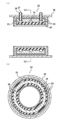
図1Aは、本発明の実施形態1に係る筒状缶体12の筒状部材15の軸方向に平行な断面模式図である。図1Bは、図1AにおけるL1-L1断面の断面模式図である。
以上のようにして、本発明の実施形態1に係る筒状缶体12及びそれを備えた誘導加熱触媒装置10が得られる。
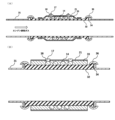
図2Aは、本発明の実施形態2に係る筒状缶体22の筒状部材25の軸方向に平行な断面模式図である。図2Bは、図2AにおけるL2-L2断面の断面模式図である。
以上のようにして、本発明の実施形態2に係る筒状缶体22及びそれを備えた誘導加熱触媒装置が得られる。
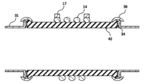
図3Aは、本発明の実施形態3に係る筒状缶体32の軸方向に平行な断面模式図である。図3Bは、図3Aで示す筒状缶体32の拡大模式図である。図3A、図3Bでは、筒状缶体32が、そのガス流入側とガス流出側とに、エンジンの排気ガスの流路となる金属排気管31が接続されている様子を示している。金属排気管31は、筒状缶体32の両端において、それぞれガスケット34を介して固定部材36によって固定されている。なお、金属排気管31と筒状缶体32との固定方法については、上記の他に、接着剤による接合、メカニカルな組付け部材による結合、圧入、焼き嵌めなどが挙げられる。
以上のようにして、本発明の実施形態3に係る筒状缶体32及びそれを備えた誘導加熱触媒装置が得られる。
図4は、本発明の実施形態4に係る筒状缶体42の軸方向に平行な断面模式図である。本発明の実施形態4に係る筒状缶体42は、上述の実施形態3に係る筒状缶体32において、コイル14の表面に緩衝部材33が設けられていない点、及び、電磁遮蔽層21が設けられていない点以外は、同様の構成である。
図5は、本発明の実施形態5に係る筒状缶体52の軸方向に平行な断面模式図である。筒状缶体52は、絶縁材料で構成され、ハニカム構造体を誘導加熱するためのコイル14を有している。
以上のようにして、本発明の実施形態5に係る筒状缶体52及びそれを備えた誘導加熱触媒装置が得られる。
図6は、本発明の実施形態6に係る筒状缶体62の軸方向に平行な断面模式図である。実施形態6に係る筒状缶体62は、上述の実施形態5で示した筒状缶体52において、コイル64の断面形状が楕円ではなく、略長方形であること以外は、同様の構成を有している。このような構成によれば、実施形態1と同様に、筒状缶体62の内面にコイル64が露出していないため、ハニカム構造体を誘導加熱するためのコイル64に接続させる電気配線を簡易な構造とし、コイル回りの絶縁性を向上させる等の効果を有する。
図7は、本発明の実施形態7に係る筒状缶体72の軸方向に平行な断面模式図である。実施形態7に係る筒状缶体72は、上述の実施形態4で示した筒状缶体42において、コイル74の断面形状が楕円ではなく、略長方形であること以外は、同様の構成を有している。このような構成によれば、実施形態1と同様に、筒状缶体72の内面にコイル74が露出していないため、ハニカム構造体を誘導加熱するためのコイル74に接続させる電気配線を簡易な構造とし、コイル回りの絶縁性を向上させる等の効果を有する。
11 ハニカム構造体
12、22、32、42、52、62、72 筒状缶体
13、23、33 緩衝部材
14、64、74 コイル
15、25 筒状部材
16 金属部材
17 電気接続端子
18 絶縁材
19 磁性体
21 電磁遮蔽層
31 金属排気管
34 ガスケット
36 固定部材
58 緩衝層
Claims (8)
- ハニカム構造体を内部に収容可能な筒状缶体であって、
前記ハニカム構造体を誘導加熱するためのコイルと、
絶縁材料で構成された筒状部材と、
前記コイル及び前記筒状部材を内部に収容可能な筒状の金属部材と、を有し、
前記筒状部材の軸方向に平行な断面において、
(i)前記コイルが、前記筒状部材の内周面より径方向外側に設けられ、且つ、前記筒状部材の断面内に少なくとも一部が埋め込まれている、または、
(ii)前記コイルが前記筒状部材の外周部に設けられており、
前記筒状部材の軸方向に平行な断面において、前記コイルと前記筒状部材とを内部に収容するように、緩衝部材が設けられている、
筒状缶体。 - 前記筒状缶体の軸方向に平行な断面において、前記コイルと前記筒状の金属部材との間に、電磁遮蔽層をさらに備える、請求項1に記載の筒状缶体。
- ハニカム構造体を内部に収容可能な筒状缶体であって、
前記筒状缶体が、前記ハニカム構造体を誘導加熱するためのコイルを有し、
前記筒状缶体が、絶縁材料で構成されており、
前記筒状缶体の軸方向に平行な断面において、
(i)前記コイルが、前記筒状缶体の内周面より径方向外側に設けられ、且つ、前記筒状缶体の断面内に少なくとも一部が埋め込まれている、または、
(ii)前記コイルが前記筒状缶体の軸方向に平行な断面において、前記筒状缶体の外周部に設けられており、
前記コイルの表面が緩衝材で保持されている、
筒状缶体。 - 前記筒状缶体の軸方向に平行な断面において、前記コイルよりも径方向外側に位置する電磁遮蔽層をさらに備える、請求項3に記載の筒状缶体。
- 前記絶縁材料が、窒化珪素、サイアロン、炭化珪素、コーディエライト、アルミナ、ジルコニア、シリカ及びムライトのいずれか一種を主成分とするか、またはこれらの複合材料を主成分とする、請求項1~4のいずれか一項に記載の筒状缶体。
- 前記絶縁材料が、アルミナ繊維強化材料またはムライト繊維強化材料である、請求項5に記載の筒状缶体。
- 前記筒状缶体が、外周壁と、前記外周壁の内側に配設され、一方の端面から他方の端面まで貫通して流路を形成する複数のセルを区画形成する隔壁と、を有し、磁性体を備える柱状のハニカム構造体をさらに備える、請求項1~6のいずれか一項に記載の筒状缶体。
- 請求項1に記載の筒状缶体と、前記緩衝部材を介して前記筒状缶体の内部に収容された磁性体を備えるハニカム構造体と、を有する、誘導加熱触媒装置。
Applications Claiming Priority (3)
| Application Number | Priority Date | Filing Date | Title |
|---|---|---|---|
| JP2020184568 | 2020-11-04 | ||
| JP2020184568 | 2020-11-04 | ||
| PCT/JP2021/019857 WO2022097318A1 (ja) | 2020-11-04 | 2021-05-25 | 筒状缶体及び誘導加熱触媒装置 |
Publications (2)
| Publication Number | Publication Date |
|---|---|
| JPWO2022097318A1 JPWO2022097318A1 (ja) | 2022-05-12 |
| JP7581366B2 true JP7581366B2 (ja) | 2024-11-12 |
Family
ID=81457676
Family Applications (1)
| Application Number | Title | Priority Date | Filing Date |
|---|---|---|---|
| JP2022560634A Active JP7581366B2 (ja) | 2020-11-04 | 2021-05-25 | 筒状缶体及び誘導加熱触媒装置 |
Country Status (5)
| Country | Link |
|---|---|
| US (1) | US12065957B2 (ja) |
| JP (1) | JP7581366B2 (ja) |
| CN (1) | CN116234628A (ja) |
| DE (1) | DE112021005266T5 (ja) |
| WO (1) | WO2022097318A1 (ja) |
Families Citing this family (4)
| Publication number | Priority date | Publication date | Assignee | Title |
|---|---|---|---|---|
| JP7742080B2 (ja) * | 2022-11-04 | 2025-09-19 | 日本碍子株式会社 | 誘導加熱装置 |
| JPWO2024171532A1 (ja) * | 2023-02-17 | 2024-08-22 | ||
| WO2025121167A1 (ja) * | 2023-12-08 | 2025-06-12 | 日本碍子株式会社 | ガス熱分解ユニット及びガス熱分解装置 |
| WO2025182518A1 (ja) * | 2024-02-29 | 2025-09-04 | 日本碍子株式会社 | ガス反応合成ユニット及びガス反応合成装置 |
Citations (2)
| Publication number | Priority date | Publication date | Assignee | Title |
|---|---|---|---|---|
| US20170022868A1 (en) | 2013-09-18 | 2017-01-26 | Advanced Technology Emission Solutions Inc. | Apparatus and method for gaseous emissions treatment with enhanced catalyst distribution |
| JP2019163760A (ja) | 2018-03-20 | 2019-09-26 | 日本碍子株式会社 | 流体加熱部品、及び流体加熱部品複合体 |
Family Cites Families (11)
| Publication number | Priority date | Publication date | Assignee | Title |
|---|---|---|---|---|
| JPH0828250A (ja) * | 1994-07-18 | 1996-01-30 | Shimadzu Corp | 自動車用誘導発熱式触媒コンバータ |
| JP3377617B2 (ja) * | 1994-09-07 | 2003-02-17 | 電気興業株式会社 | 排気ガス浄化装置 |
| US10626766B2 (en) * | 2013-09-18 | 2020-04-21 | Advanced Technology Emission Solutions Inc. | Gaseous emissions treatment system with enhanced induction heating and method of use |
| US10975747B2 (en) * | 2012-08-24 | 2021-04-13 | Advanced Technology Emission Solutions Inc. | Gaseous emissions treatment structures |
| US9617888B2 (en) | 2013-09-18 | 2017-04-11 | Advanced Technology Emission Solutions Inc. | Catalytic converter structures with electrohydrodynamic heat and mass transfer |
| US20180353892A1 (en) * | 2015-11-25 | 2018-12-13 | Corning Incorporated | Honeycomb body thermal barrier, exhaust gas treatment article, exhaust system, and methods of manufacturing same |
| EP3454984A4 (en) * | 2016-05-11 | 2019-12-18 | BASF Corporation | CATALYST COMPOSITION WITH MAGNETIC MATERIAL ADAPTED FOR INDUCTIVE HEATING |
| JP6585548B2 (ja) * | 2016-06-01 | 2019-10-02 | 株式会社クボタ | ディーゼルエンジンの排気処理装置 |
| JP7154139B2 (ja) * | 2018-03-20 | 2022-10-17 | 日本碍子株式会社 | 流体加熱部品、流体加熱部品複合体、及び流体加熱部品の製造方法 |
| US11310873B2 (en) | 2018-03-20 | 2022-04-19 | Ngk Insulators, Ltd. | Fluid heating component, and fluid heating component complex |
| JP7042671B2 (ja) * | 2018-03-29 | 2022-03-28 | 日本碍子株式会社 | 導電性ハニカム構造体 |
-
2021
- 2021-05-25 DE DE112021005266.7T patent/DE112021005266T5/de active Pending
- 2021-05-25 WO PCT/JP2021/019857 patent/WO2022097318A1/ja not_active Ceased
- 2021-05-25 JP JP2022560634A patent/JP7581366B2/ja active Active
- 2021-05-25 CN CN202180066702.8A patent/CN116234628A/zh active Pending
-
2023
- 2023-02-07 US US18/165,435 patent/US12065957B2/en active Active
Patent Citations (2)
| Publication number | Priority date | Publication date | Assignee | Title |
|---|---|---|---|---|
| US20170022868A1 (en) | 2013-09-18 | 2017-01-26 | Advanced Technology Emission Solutions Inc. | Apparatus and method for gaseous emissions treatment with enhanced catalyst distribution |
| JP2019163760A (ja) | 2018-03-20 | 2019-09-26 | 日本碍子株式会社 | 流体加熱部品、及び流体加熱部品複合体 |
Also Published As
| Publication number | Publication date |
|---|---|
| US12065957B2 (en) | 2024-08-20 |
| US20230184151A1 (en) | 2023-06-15 |
| CN116234628A (zh) | 2023-06-06 |
| JPWO2022097318A1 (ja) | 2022-05-12 |
| DE112021005266T5 (de) | 2023-09-07 |
| WO2022097318A1 (ja) | 2022-05-12 |
Similar Documents
| Publication | Publication Date | Title |
|---|---|---|
| JP7581366B2 (ja) | 筒状缶体及び誘導加熱触媒装置 | |
| JP5692198B2 (ja) | ハニカム構造体 | |
| JP7486605B2 (ja) | ハニカム構造体、排気ガス浄化装置及びハニカム構造体の製造方法 | |
| WO2005105705A1 (ja) | ハニカム構造体及びその製造方法 | |
| US11219100B2 (en) | Fluid heating component, fluid heating component complex, and manufacturing method of fluid heating component | |
| JPWO2020031434A1 (ja) | ハニカム構造体、排気ガス浄化装置、排気システム及びハニカム構造体の製造方法 | |
| US12257574B2 (en) | Honeycomb structure, exhaust gas purification catalyst, and exhaust gas purification system | |
| JP7034376B2 (ja) | ハニカム構造体及び排気ガス浄化装置 | |
| US12383852B2 (en) | Honeycomb structure and exhaust gas purifying device | |
| JP7481485B2 (ja) | 触媒担体及び誘導加熱触媒システム | |
| CN114302764A (zh) | 蜂窝结构体及尾气净化装置 | |
| JP2024094600A (ja) | メタルハニカム体、触媒コンバータ、メタルハニカム体の製造方法 | |
| JP2024067516A (ja) | 誘導加熱装置 | |
| JP7368614B2 (ja) | ハニカム構造体及び排気ガス浄化装置 | |
| US11858170B2 (en) | Method for producing honeycomb structure | |
| US20230313721A1 (en) | Honeycomb structure, electrically heated carrier, and exhaust gas purification device | |
| JP2022072369A (ja) | 接合体および接合体の製造方法 | |
| JP2025139762A (ja) | メタルハニカム体、触媒コンバータ、メタルハニカム体の製造方法 | |
| JP2024133938A (ja) | メタルハニカム体、触媒コンバータ、メタルハニカム体の製造方法 | |
| JP2017160096A (ja) | 繊維強化多孔体 | |
| JPH0975753A (ja) | ハニカム体およびその製造方法 |
Legal Events
| Date | Code | Title | Description |
|---|---|---|---|
| A621 | Written request for application examination |
Free format text: JAPANESE INTERMEDIATE CODE: A621 Effective date: 20221116 |
|
| A131 | Notification of reasons for refusal |
Free format text: JAPANESE INTERMEDIATE CODE: A131 Effective date: 20231116 |
|
| A521 | Request for written amendment filed |
Free format text: JAPANESE INTERMEDIATE CODE: A523 Effective date: 20231222 |
|
| A131 | Notification of reasons for refusal |
Free format text: JAPANESE INTERMEDIATE CODE: A131 Effective date: 20240206 |
|
| A521 | Request for written amendment filed |
Free format text: JAPANESE INTERMEDIATE CODE: A523 Effective date: 20240404 |
|
| A131 | Notification of reasons for refusal |
Free format text: JAPANESE INTERMEDIATE CODE: A131 Effective date: 20240613 |
|
| A521 | Request for written amendment filed |
Free format text: JAPANESE INTERMEDIATE CODE: A523 Effective date: 20240723 |
|
| TRDD | Decision of grant or rejection written | ||
| A01 | Written decision to grant a patent or to grant a registration (utility model) |
Free format text: JAPANESE INTERMEDIATE CODE: A01 Effective date: 20241008 |
|
| A61 | First payment of annual fees (during grant procedure) |
Free format text: JAPANESE INTERMEDIATE CODE: A61 Effective date: 20241030 |
|
| R150 | Certificate of patent or registration of utility model |
Ref document number: 7581366 Country of ref document: JP Free format text: JAPANESE INTERMEDIATE CODE: R150 |