JP7581366B2 - Cylindrical can body and induction heating catalyst device - Google Patents
Cylindrical can body and induction heating catalyst device Download PDFInfo
- Publication number
- JP7581366B2 JP7581366B2 JP2022560634A JP2022560634A JP7581366B2 JP 7581366 B2 JP7581366 B2 JP 7581366B2 JP 2022560634 A JP2022560634 A JP 2022560634A JP 2022560634 A JP2022560634 A JP 2022560634A JP 7581366 B2 JP7581366 B2 JP 7581366B2
- Authority
- JP
- Japan
- Prior art keywords
- cylindrical
- coil
- honeycomb structure
- cross
- induction heating
- Prior art date
- Legal status (The legal status is an assumption and is not a legal conclusion. Google has not performed a legal analysis and makes no representation as to the accuracy of the status listed.)
- Active
Links
Images


Classifications
-
- F—MECHANICAL ENGINEERING; LIGHTING; HEATING; WEAPONS; BLASTING
- F01—MACHINES OR ENGINES IN GENERAL; ENGINE PLANTS IN GENERAL; STEAM ENGINES
- F01N—GAS-FLOW SILENCERS OR EXHAUST APPARATUS FOR MACHINES OR ENGINES IN GENERAL; GAS-FLOW SILENCERS OR EXHAUST APPARATUS FOR INTERNAL-COMBUSTION ENGINES
- F01N3/00—Exhaust or silencing apparatus having means for purifying, rendering innocuous, or otherwise treating exhaust
- F01N3/08—Exhaust or silencing apparatus having means for purifying, rendering innocuous, or otherwise treating exhaust for rendering innocuous
- F01N3/10—Exhaust or silencing apparatus having means for purifying, rendering innocuous, or otherwise treating exhaust for rendering innocuous by thermal or catalytic conversion of noxious components of exhaust
- F01N3/18—Exhaust or silencing apparatus having means for purifying, rendering innocuous, or otherwise treating exhaust for rendering innocuous by thermal or catalytic conversion of noxious components of exhaust characterised by methods of operation; Control
- F01N3/20—Exhaust or silencing apparatus having means for purifying, rendering innocuous, or otherwise treating exhaust for rendering innocuous by thermal or catalytic conversion of noxious components of exhaust characterised by methods of operation; Control specially adapted for catalytic conversion
- F01N3/2006—Periodically heating or cooling catalytic reactors, e.g. at cold starting or overheating
- F01N3/2013—Periodically heating or cooling catalytic reactors, e.g. at cold starting or overheating using electric or magnetic heating means
-
- B—PERFORMING OPERATIONS; TRANSPORTING
- B01—PHYSICAL OR CHEMICAL PROCESSES OR APPARATUS IN GENERAL
- B01D—SEPARATION
- B01D53/00—Separation of gases or vapours; Recovering vapours of volatile solvents from gases; Chemical or biological purification of waste gases, e.g. engine exhaust gases, smoke, fumes, flue gases, aerosols
- B01D53/34—Chemical or biological purification of waste gases
- B01D53/92—Chemical or biological purification of waste gases of engine exhaust gases
- B01D53/94—Chemical or biological purification of waste gases of engine exhaust gases by catalytic processes
-
- F—MECHANICAL ENGINEERING; LIGHTING; HEATING; WEAPONS; BLASTING
- F01—MACHINES OR ENGINES IN GENERAL; ENGINE PLANTS IN GENERAL; STEAM ENGINES
- F01N—GAS-FLOW SILENCERS OR EXHAUST APPARATUS FOR MACHINES OR ENGINES IN GENERAL; GAS-FLOW SILENCERS OR EXHAUST APPARATUS FOR INTERNAL-COMBUSTION ENGINES
- F01N3/00—Exhaust or silencing apparatus having means for purifying, rendering innocuous, or otherwise treating exhaust
- F01N3/08—Exhaust or silencing apparatus having means for purifying, rendering innocuous, or otherwise treating exhaust for rendering innocuous
- F01N3/10—Exhaust or silencing apparatus having means for purifying, rendering innocuous, or otherwise treating exhaust for rendering innocuous by thermal or catalytic conversion of noxious components of exhaust
- F01N3/24—Exhaust or silencing apparatus having means for purifying, rendering innocuous, or otherwise treating exhaust for rendering innocuous by thermal or catalytic conversion of noxious components of exhaust characterised by constructional aspects of converting apparatus
- F01N3/28—Construction of catalytic reactors
- F01N3/2803—Construction of catalytic reactors characterised by structure, by material or by manufacturing of catalyst support
- F01N3/2825—Ceramics
- F01N3/2828—Ceramic multi-channel monoliths, e.g. honeycombs
-
- H—ELECTRICITY
- H05—ELECTRIC TECHNIQUES NOT OTHERWISE PROVIDED FOR
- H05B—ELECTRIC HEATING; ELECTRIC LIGHT SOURCES NOT OTHERWISE PROVIDED FOR; CIRCUIT ARRANGEMENTS FOR ELECTRIC LIGHT SOURCES, IN GENERAL
- H05B6/00—Heating by electric, magnetic or electromagnetic fields
- H05B6/02—Induction heating
- H05B6/10—Induction heating apparatus, other than furnaces, for specific applications
-
- F—MECHANICAL ENGINEERING; LIGHTING; HEATING; WEAPONS; BLASTING
- F01—MACHINES OR ENGINES IN GENERAL; ENGINE PLANTS IN GENERAL; STEAM ENGINES
- F01N—GAS-FLOW SILENCERS OR EXHAUST APPARATUS FOR MACHINES OR ENGINES IN GENERAL; GAS-FLOW SILENCERS OR EXHAUST APPARATUS FOR INTERNAL-COMBUSTION ENGINES
- F01N2240/00—Combination or association of two or more different exhaust treating devices, or of at least one such device with an auxiliary device, not covered by indexing codes F01N2230/00 or F01N2250/00, one of the devices being
- F01N2240/05—Combination or association of two or more different exhaust treating devices, or of at least one such device with an auxiliary device, not covered by indexing codes F01N2230/00 or F01N2250/00, one of the devices being a magnetic, e.g. electromagnetic, device other than a valve
-
- F—MECHANICAL ENGINEERING; LIGHTING; HEATING; WEAPONS; BLASTING
- F01—MACHINES OR ENGINES IN GENERAL; ENGINE PLANTS IN GENERAL; STEAM ENGINES
- F01N—GAS-FLOW SILENCERS OR EXHAUST APPARATUS FOR MACHINES OR ENGINES IN GENERAL; GAS-FLOW SILENCERS OR EXHAUST APPARATUS FOR INTERNAL-COMBUSTION ENGINES
- F01N2240/00—Combination or association of two or more different exhaust treating devices, or of at least one such device with an auxiliary device, not covered by indexing codes F01N2230/00 or F01N2250/00, one of the devices being
- F01N2240/16—Combination or association of two or more different exhaust treating devices, or of at least one such device with an auxiliary device, not covered by indexing codes F01N2230/00 or F01N2250/00, one of the devices being an electric heater, i.e. a resistance heater
-
- F—MECHANICAL ENGINEERING; LIGHTING; HEATING; WEAPONS; BLASTING
- F01—MACHINES OR ENGINES IN GENERAL; ENGINE PLANTS IN GENERAL; STEAM ENGINES
- F01N—GAS-FLOW SILENCERS OR EXHAUST APPARATUS FOR MACHINES OR ENGINES IN GENERAL; GAS-FLOW SILENCERS OR EXHAUST APPARATUS FOR INTERNAL-COMBUSTION ENGINES
- F01N2330/00—Structure of catalyst support or particle filter
- F01N2330/06—Ceramic, e.g. monoliths
-
- F—MECHANICAL ENGINEERING; LIGHTING; HEATING; WEAPONS; BLASTING
- F01—MACHINES OR ENGINES IN GENERAL; ENGINE PLANTS IN GENERAL; STEAM ENGINES
- F01N—GAS-FLOW SILENCERS OR EXHAUST APPARATUS FOR MACHINES OR ENGINES IN GENERAL; GAS-FLOW SILENCERS OR EXHAUST APPARATUS FOR INTERNAL-COMBUSTION ENGINES
- F01N2330/00—Structure of catalyst support or particle filter
- F01N2330/30—Honeycomb supports characterised by their structural details
- F01N2330/34—Honeycomb supports characterised by their structural details with flow channels of polygonal cross section
Landscapes
- Chemical & Material Sciences (AREA)
- Engineering & Computer Science (AREA)
- Chemical Kinetics & Catalysis (AREA)
- Combustion & Propulsion (AREA)
- Health & Medical Sciences (AREA)
- General Engineering & Computer Science (AREA)
- Toxicology (AREA)
- Mechanical Engineering (AREA)
- Ceramic Engineering (AREA)
- Environmental & Geological Engineering (AREA)
- Electromagnetism (AREA)
- Biomedical Technology (AREA)
- Physics & Mathematics (AREA)
- Analytical Chemistry (AREA)
- General Chemical & Material Sciences (AREA)
- Oil, Petroleum & Natural Gas (AREA)
- Exhaust Gas After Treatment (AREA)
- Exhaust Gas Treatment By Means Of Catalyst (AREA)
- General Induction Heating (AREA)
Description
本発明は、筒状缶体及び誘導加熱触媒装置に関する。 The present invention relates to a cylindrical can body and an induction heating catalyst device.
自動車の排気ガスには、通常は不完全燃焼の結果として一酸化炭素、炭化水素、窒素酸化物などの有害成分やカーボンなどの微粒子が含まれることがある。これらの有害成分は、エンジン始動直後という、触媒温度が低く、触媒活性が不十分な期間に排出されている。このため、排気ガス中の有害成分が、触媒活性化温度に達する前に触媒で浄化されずに排出されるおそれがある。このような要求に応えるためには、触媒活性化温度に達する前に触媒で浄化されずに排出されるエミッションを極力低減させることが必要であり、例えば、電気加熱技術を利用した対策が知られている。 Automobile exhaust gases can contain harmful components such as carbon monoxide, hydrocarbons, and nitrogen oxides, as well as fine particles such as carbon, usually as a result of incomplete combustion. These harmful components are emitted immediately after the engine is started, when the catalyst temperature is low and catalytic activity is insufficient. This means that there is a risk that harmful components in the exhaust gas will be emitted without being purified by the catalyst before the catalyst activation temperature is reached. To meet these demands, it is necessary to minimize the emissions that are emitted without being purified by the catalyst before the catalyst activation temperature is reached. For example, measures that utilize electric heating technology are known.
特許文献1には、金属管内部に金属ワイヤを挿入した触媒担体を設け、さらに触媒担体の周囲にコイルを配置した触媒コンバーターに係る発明が開示されている。当該触媒コンバーターでは、コイルに電流を流して触媒担体を誘導加熱することで、触媒を活性化させて排気ガスを浄化している。 Patent Document 1 discloses an invention relating to a catalytic converter in which a catalyst carrier is provided with a metal wire inserted inside a metal tube, and a coil is further arranged around the catalyst carrier. In this catalytic converter, an electric current is passed through the coil to inductively heat the catalyst carrier, activating the catalyst and purifying exhaust gas.
特許文献1では、コイルを触媒担体と共に金属管内部に配置している。このように金属管内部にコイルを配置すると、外部電源からの電流を流すためにコイルに接続する電気配線の構造が複雑になるおそれがある。また、排気ガスからの凝縮水によってコイル回りの絶縁が不十分となり、改善の必要があるものであった。In Patent Document 1, the coil is placed inside the metal tube together with the catalyst carrier. Placing the coil inside the metal tube in this way may result in a complex structure of electrical wiring connected to the coil to pass current from an external power source. In addition, condensation from the exhaust gas causes insufficient insulation around the coil, which was something that needed to be improved.
本発明は上記事情に鑑みて創作されたものであり、ハニカム構造体を誘導加熱するためのコイルに接続させる電気配線を簡易な構造とし、コイル回りの絶縁性を向上させることができる筒状缶体及び誘導加熱触媒装置を提供することを課題とする。The present invention was created in consideration of the above circumstances, and its objective is to provide a cylindrical can body and an induction heating catalyst device that have a simple structure for the electrical wiring that connects the honeycomb structure to a coil for induction heating, and that can improve the insulation around the coil.
上記課題は、以下の本発明によって解決されるものであり、本発明は以下のように特定される。
(1)ハニカム構造体を内部に収容可能な筒状缶体であって、
前記ハニカム構造体を誘導加熱するためのコイルと、
絶縁材料で構成された筒状部材と、
前記コイル及び前記筒状部材を内部に収容可能な筒状の金属部材と、を有し、
前記筒状部材の軸方向に平行な断面において、
(i)前記コイルが、前記筒状部材の内周面より径方向外側に設けられ、且つ、前記筒状部材の断面内に少なくとも一部が埋め込まれている、または、
(ii)前記コイルが前記筒状部材の外周部に設けられている、
筒状缶体。
(2)ハニカム構造体を内部に収容可能な筒状缶体であって、
前記筒状缶体が、前記ハニカム構造体を誘導加熱するためのコイルを有し、
前記筒状缶体が、絶縁材料で構成されており、
前記筒状缶体の軸方向に平行な断面において、
(i)前記コイルが、前記筒状缶体の内周面より径方向外側に設けられ、且つ、前記筒状缶体の断面内に少なくとも一部が埋め込まれている、または、
(ii)前記コイルが前記筒状缶体の外周部に設けられている、
筒状缶体。
(3)(1)または(2)に記載の筒状缶体と、緩衝部材を介して前記筒状缶体の内部に収容された磁性体を備えるハニカム構造体と、を有する、誘導加熱触媒装置。
The above problems are solved by the present invention, which is specified as follows:
(1) A cylindrical can body capable of housing a honeycomb structure therein,
A coil for induction heating the honeycomb structure;
A cylindrical member made of an insulating material;
a cylindrical metal member capable of accommodating the coil and the cylindrical member therein,
In a cross section parallel to the axial direction of the cylindrical member,
(i) the coil is provided radially outward from an inner circumferential surface of the tubular member, and at least a portion of the coil is embedded in a cross section of the tubular member, or
(ii) the coil is provided on the outer periphery of the cylindrical member;
Cylindrical can body.
(2) A cylindrical can body capable of housing a honeycomb structure therein,
the cylindrical can body has a coil for induction heating the honeycomb structure,
The cylindrical can body is made of an insulating material,
In a cross section parallel to the axial direction of the cylindrical can body,
(i) the coil is provided radially outward from the inner circumferential surface of the cylindrical can body, and at least a portion of the coil is embedded in a cross section of the cylindrical can body, or
(ii) the coil is provided on the outer periphery of the cylindrical can body;
Cylindrical can body.
(3) An induction heating catalyst device comprising: the cylindrical can body according to (1) or (2); and a honeycomb structure having a magnetic body housed inside the cylindrical can body via a buffer member.
本発明によれば、ハニカム構造体を誘導加熱するためのコイルに接続させる電気配線を簡易な構造とし、コイル回りの絶縁性を向上させる筒状缶体及び誘導加熱触媒装置を提供することができる。According to the present invention, it is possible to provide a cylindrical can body and an induction heating catalyst device that have a simple structure for the electrical wiring that connects the honeycomb structure to a coil for induction heating, thereby improving the insulation around the coil.
次に本発明を実施するための形態を、図面を参照しながら詳細に説明する。本発明は以下の実施形態に限定されるものではなく、本発明の趣旨を逸脱しない範囲で、当業者の通常の知識に基づいて、適宜設計の変更、改良等が加えられることが理解されるべきである。Next, the embodiments for carrying out the present invention will be described in detail with reference to the drawings. It should be understood that the present invention is not limited to the following embodiments, and that appropriate design changes, improvements, etc. may be made based on the ordinary knowledge of those skilled in the art without departing from the spirit of the present invention.
<実施形態1>
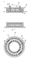
図1Aは、本発明の実施形態1に係る筒状缶体12の筒状部材15の軸方向に平行な断面模式図である。図1Bは、図1AにおけるL1-L1断面の断面模式図である。
<Embodiment 1>
Fig. 1A is a schematic cross-sectional view parallel to the axial direction of a
筒状缶体12は、ハニカム構造体を誘導加熱するためのコイル14と、絶縁材料で構成された筒状部材15と、コイル14及び筒状部材15を内部に収容可能な筒状の金属部材16とを有している。筒状缶体12は、ハニカム構造体を内部に収容可能に構成されており、その構成要素として、ハニカム構造体を備えても良く、備えていなくてもよい。The
ハニカム構造体を誘導加熱するためのコイル14は、筒状部材15の周面に沿って周回するように配置され、ハニカム構造体の外側を周回可能に配置されている。コイル14は、IHコイルとして公知の材料を用いて形成することができる。具体的には、銅などが挙げられる。コイル14の断面は特に限定されず、略正方形、略長方形、楕円形、円形等であってもよい。また、ポリアミドイミド被膜等により絶縁被膜された銅線を束ねた、いわゆるリッツ線を用いても良い。The
コイル14には、電気配線を接続するための電気接続端子17が接続されている。当該電気配線は、外部電源に接続されている。当該電気配線を通って、電流がコイル14へ流れ、誘導加熱が行われる。電気接続端子17は、筒状の金属部材16の外側から貫通孔を介して、筒状缶体12の径方向に挿入されることで、コイル14に接続されている。電気接続端子17は絶縁材18で覆われている。An
コイル14は、絶縁材料で構成された筒状部材15の軸方向に平行な断面において、筒状部材15の内周面より径方向外側に設けられている。また、コイル14は絶縁材料で構成された筒状部材15の断面内に埋め込まれている。なお、図1ではこのように、コイル14が絶縁材料で構成された筒状部材15の断面内に埋め込まれている構成を示している。本発明では、これに限らず、コイル14は、筒状部材15の軸方向に平行な断面において、筒状部材15の内周面より径方向外側に設けられている限り、筒状部材15の断面内に少なくとも一部が埋め込まれた構成を有することができる。このような構成によれば、筒状部材15の内面にコイル14が露出していないため、ハニカム構造体を誘導加熱するためのコイル14に接続させる電気配線を簡易な構造とすることができる。また、従来のように金属配管内部にコイルを配置する構成であるとき、ハニカム構造体へのキャニングマット(緩衝部材)面圧の管理が困難であり、使用時にハニカム構造体を保持する力を維持することができないという問題がある。これに対し、本発明の実施形態によれば、コイル14は筒状部材15の内面に露出していないため、キャニングマット面圧の管理が容易となり、使用時にハニカム構造体の保持力を容易に維持することができる。さらに、本発明の実施形態によれば、コイル14は筒状部材15の内面に露出していないため、使用時に排気ガスからの凝縮水でコイル14が濡れることを抑制し、コイル14周りの絶縁性を良好に維持することができる。The
コイル14の表面を緩衝層で覆ってもよい。このような構成によれば、コイル14を保護することで、コイル14の酸化などの劣化を抑制することができる。The surface of the
筒状部材15を構成する絶縁材料は、窒化珪素、サイアロン、炭化珪素、コーディエライト、アルミナ、ジルコニア、シリカ及びムライトのいずれか一種を主成分とするか、またはこれらの複合材料を主成分とすることができる。また、絶縁材料としては、アルミナ繊維強化材料またはムライト繊維強化材料を用いると、熱応力破壊に対する信頼性の点で好ましい。ここで、主成分とは、筒状部材15の組成分に対して、50超質量%であることを意味し、好ましくは80質量%以上であり、より好ましくは90質量%以上である。The insulating material constituting the
筒状部材15の厚さは、コイル14を埋め込むことができる大きさであれば特に限定されず、例えば、5~40mmに形成することができ、10~30mmに形成することができる。The thickness of the
筒状の金属部材16は、コイル14及び筒状部材15を内部に収容可能に形成されている。筒状の金属部材16としては、公知の金属材料を用いることができる。例えば、ステンレス、チタン合金、銅合金、アルミ合金、真鍮などが挙げられる。その中でも、耐久信頼性が高く、安価という理由により、ステンレスが好ましい。The
筒状の金属部材16の厚みは、特に限定されないが、好ましくは0.5mm以上、より好ましくは1mm以上である。筒状の金属部材16の厚み0.5mm以上とすることにより、耐久性を確保することができる。また、筒状の金属部材16の厚みは、5mm以下が好ましく、3mm以下がより好ましい。筒状の金属部材16の厚みを5mm以下とすることにより、軽量化することができる。The thickness of the
筒状缶体12は、軸方向に平行な断面において、コイル14と筒状の金属部材16との間に、電磁遮蔽層21を備えている。図1に示す形態では、電磁遮蔽層21は、コイル14を内部に埋め込んでいる筒状部材15の外側を覆うように設けられている。電磁遮蔽層21をコイル14と筒状の金属部材16との間に設けることで、誘導加熱の際にコイル14によって発生する電磁波を電磁遮蔽層21内で遮断することができる。電磁遮蔽層21の構成材料としては、特に限定されず、公知の材料、例えばフェライト、珪素鉄、パーメンジュール、電磁ステンレス等を用いることができる。なお、筒状缶体12に電磁遮蔽層21を設けなくてもよい。電磁遮蔽層21の厚さは、0.3~10mmであるのが好ましく、1~5mmであるのがより好ましい。The
筒状部材15を覆う電磁遮蔽層21と筒状の金属部材16との間に、緩衝部材13が設けられている。また、筒状缶体12には、内部にハニカム構造体を収容したとき、ハニカム構造体と筒状部材15との間に配置されるように、緩衝部材13が設けられている。緩衝部材13としては、公知の材料を用いることができ、例えばセラミックファイバーまたはガラスファイバー等で構成することができる。A
本発明の実施形態1に係る筒状缶体12及びそれを備えた誘導加熱触媒装置10の製造方法を以下に説明する。本発明の実施形態1に係る筒状缶体12及びそれを備えた誘導加熱触媒装置10の製造方法は、後述する磁性体を備えたハニカム構造体を準備する工程、コイルを埋め込んだ筒状部材の製造工程、及び、緩衝部材13を介して筒状部材内にハニカム構造体を収容する工程を備えている。A method for manufacturing the
コイルを埋め込んだ筒状部材の製造工程では、まず、銅製等のコイルを準備し、ハニカム構造体の外周を周回するような形状となるように設ける。次に、コイルを鋳型内に配置し、当該鋳型内に、絶縁材料(筒状部材の原料)スラリーを流し込んで焼成する。これにより、コイルを埋め込んだ筒状部材が得られる。また、筒状部材の外周の所定位置にフェライトなどを用いた薄肉部品を設けることで、電磁遮蔽層を形成する。また、絶縁材料スラリーを用いずに、粉末原料内にコイルを置き、静水圧加圧後焼成して筒状部材を製造してもよい。焼成の方法として、ホットプレス焼成を用いても良い。In the manufacturing process of the tubular member with an embedded coil, first, a coil made of copper or the like is prepared and shaped so that it wraps around the outer periphery of the honeycomb structure. Next, the coil is placed in a mold, and an insulating material (raw material for the tubular member) slurry is poured into the mold and fired. This results in a tubular member with an embedded coil. Also, an electromagnetic shielding layer is formed by providing a thin-walled part made of ferrite or the like at a predetermined position on the outer periphery of the tubular member. Alternatively, the tubular member may be manufactured by placing the coil in a powder raw material without using an insulating material slurry, applying hydrostatic pressure, and firing. Hot press firing may also be used as a firing method.
緩衝部材を介して筒状部材内にハニカム構造体を収容する工程では、まず、ハニカム構造体の外周を緩衝部材で覆い、これを筒状部材内に押し込んで収容する。次に、ハニカム構造体を内側に収容した筒状部材と筒状の金属部材とを接続する。接続に関しては、間に緩衝材を介して圧入しても良いし、焼き嵌め、ろう付け、拡散接合などの方法によって嵌合するように配置しても良い。次に、筒状の金属部材の外側から、あらかじめ形成しておいた貫通孔を介して、筒状缶体の径方向に、絶縁材で覆われた電気接続端子を挿入し、コイルに接続する。
以上のようにして、本発明の実施形態1に係る筒状缶体12及びそれを備えた誘導加熱触媒装置10が得られる。
In the process of accommodating the honeycomb structure in the cylindrical member via the buffer member, first, the outer periphery of the honeycomb structure is covered with the buffer member, and the buffer member is pressed into the cylindrical member to accommodate it. Next, the cylindrical member accommodating the honeycomb structure inside is connected to the cylindrical metal member. The connection may be made by press-fitting with the buffer member between them, or by fitting them together by a method such as shrink fitting, brazing, or diffusion bonding. Next, an electrical connection terminal covered with an insulating material is inserted radially of the cylindrical can from the outside of the cylindrical metal member through a through hole formed in advance, and connected to the coil.
In the manner described above, the
<実施形態2>
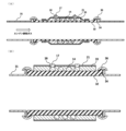
図2Aは、本発明の実施形態2に係る筒状缶体22の筒状部材25の軸方向に平行な断面模式図である。図2Bは、図2AにおけるL2-L2断面の断面模式図である。
<
Fig. 2A is a schematic cross-sectional view parallel to the axial direction of a
実施形態2に係る筒状缶体22は、コイル14が、筒状部材25の断面内に埋め込まれているのではなく、筒状部材25の外周部に設けられている点で、実施形態1に係る筒状缶体12と異なっている。また、コイル14の外側と電磁遮蔽層21との間に緩衝部材23が設けられている。それ以外は、実施形態1に係る筒状缶体12と同様の構成を有しており、実施形態1で説明した構成材料や配置等、全て同様に備えることができる。The
筒状缶体22のコイル14は、筒状部材25の外周部に設けられている。ここで、本発明において、コイル14が筒状部材25の外周部に設けられているとは、コイル14が、(1)筒状部材25の外周に接し、且つ、筒状部材25の外側に設けられている、または、(2)筒状部材25の外周付近で一部筒状部材25内に埋め込まれている部分を有し、それ以外の部分は筒状部材25の外側に設けられていることを示す。図2の例は、上記(2)の、コイル14の一部が筒状部材25内に埋め込まれている状態を示している。このような構成によれば、筒状部材25の内面にコイル14が露出していないため、ハニカム構造体を誘導加熱するためのコイル14に接続させる電気配線を簡易な構造とすることができる。また、その他、実施形態1で示したものと同様に、キャニングマット面圧の管理が容易となり、使用時にハニカム構造体の保持力を容易に維持することができる。さらに、使用時に排気ガスからの凝縮水でコイル14が濡れることを抑制し、コイル14周りの絶縁性を良好に維持することができる。The
本発明の実施形態2に係る筒状缶体22及びそれを備えた誘導加熱触媒装置の製造方法を以下に説明する。本発明の実施形態2に係る筒状缶体22及びそれを備えた誘導加熱触媒装置の製造方法は、後述する磁性体を備えたハニカム構造体を準備する工程、コイルが外周部に設けられた筒状部材の製造工程、及び、緩衝部材を介して筒状部材内にハニカム構造体を収容する工程を備えている。A method for manufacturing the
コイルが外周部に設けられた筒状部材の製造工程では、まず、銅製等のコイルを準備し、ハニカム構造体の外周を周回するような形状となるように設ける。次に、コイルを鋳型内に配置し、当該鋳型内に、絶縁材料(筒状部材の原料)スラリーを流し込んで焼成する。または、金属型にコイルを配置し、筒状部材の原料粉末を充填、加圧して成型体を得た後、ゴム製袋等の中に密閉して静水圧をかけることにより緻密な成型体を得る。その後、この成形体を焼成する。これらの方法により、コイルが外周部に設けられた筒状部材が得られる。次に、コイルが外周部に設けられた筒状部材のコイルの外側に緩衝部材(セラミックファイバー、またはガラスファイバー)を巻き、さらにその外側にフェライトなどの材質で構成された薄肉部材をメカニカルに固定して、電磁遮蔽層を形成する。In the manufacturing process of the cylindrical member with the coil on the outer periphery, first, a coil made of copper or the like is prepared and arranged so as to be shaped so as to go around the outer periphery of the honeycomb structure. Next, the coil is placed in a mold, and a slurry of insulating material (raw material of the cylindrical member) is poured into the mold and sintered. Alternatively, the coil is placed in a metal mold, and the raw material powder of the cylindrical member is filled and pressed to obtain a molded body, and then the molded body is sealed in a rubber bag or the like and subjected to hydrostatic pressure to obtain a dense molded body. Then, the molded body is sintered. By these methods, a cylindrical member with the coil on the outer periphery is obtained. Next, a buffer material (ceramic fiber or glass fiber) is wound around the outside of the coil of the cylindrical member with the coil on the outer periphery, and a thin-walled member made of a material such as ferrite is mechanically fixed to the outside of that to form an electromagnetic shielding layer.
緩衝部材を介して筒状部材内にハニカム構造体を収容する工程は、上述の実施形態1の緩衝部材を介して筒状部材内にハニカム構造体を収容する工程と同様に実施することができる。その後、上述の実施形態1と同様に、ハニカム構造体を内側に収容した筒状部材と筒状の金属部材とを接続する。
以上のようにして、本発明の実施形態2に係る筒状缶体22及びそれを備えた誘導加熱触媒装置が得られる。
The step of accommodating the honeycomb structure in the tubular member via the buffer member can be carried out in the same manner as the step of accommodating the honeycomb structure in the tubular member via the buffer member of the above-mentioned embodiment 1. Thereafter, in the same manner as the above-mentioned embodiment 1, the tubular member accommodating the honeycomb structure therein is connected to a tubular metal member.
In the manner described above, the
<実施形態3>
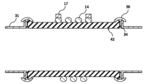
図3Aは、本発明の実施形態3に係る筒状缶体32の軸方向に平行な断面模式図である。図3Bは、図3Aで示す筒状缶体32の拡大模式図である。図3A、図3Bでは、筒状缶体32が、そのガス流入側とガス流出側とに、エンジンの排気ガスの流路となる金属排気管31が接続されている様子を示している。金属排気管31は、筒状缶体32の両端において、それぞれガスケット34を介して固定部材36によって固定されている。なお、金属排気管31と筒状缶体32との固定方法については、上記の他に、接着剤による接合、メカニカルな組付け部材による結合、圧入、焼き嵌めなどが挙げられる。
<Embodiment 3>
Fig. 3A is a schematic cross-sectional view parallel to the axial direction of a
筒状缶体32は、ハニカム構造体を誘導加熱するためのコイル14を備え、絶縁材料で構成されている。筒状缶体32の軸方向に平行な断面において、コイル14が筒状缶体32の外周部に設けられている。コイル14が筒状缶体32の外周部に設けられている態様については実施形態2で示した通りであり、これによって、実施形態2と同様に、筒状缶体32の内面にコイル14が露出していないため、ハニカム構造体を誘導加熱するためのコイル14に接続させる電気配線を簡易な構造とし、コイル回りの絶縁性を向上させる等の効果を有する。The
筒状缶体32は、コイル14の表面が緩衝材で保持されていてもよい。このような構成によれば、コイル14を保護することで、コイル14の酸化などの劣化を抑制することができる。The
筒状缶体32は、軸方向に平行な断面において、コイル14よりも外側に位置する電磁遮蔽層21を備える。このような構成によれば、誘導加熱の際にコイル14によって発生する電磁波を、電磁遮蔽層21で遮断することができる。The
本発明の実施形態3に係る筒状缶体32及びそれを備えた誘導加熱触媒装置の製造方法を以下に説明する。本発明の実施形態3に係る筒状缶体32及びそれを備えた誘導加熱触媒装置の製造方法は、磁性体を備えたハニカム構造体を準備する工程、コイルが外周部に設けられた筒状缶体の製造工程、及び、緩衝部材を介して筒状缶体内にハニカム構造体を収容する工程を備えている。A method for manufacturing the
コイルが外周部に設けられた筒状缶体の製造工程では、まず、銅製等のコイルを準備し、ハニカム構造体の外周を周回するような形状となるように設ける。次に、コイルを鋳型内に配置し、当該鋳型内に、絶縁材料(筒状缶体の原料)スラリーを流し込んで焼成する。または、金属型にコイルを配置し、筒状部材の原料粉末を充填、加圧して成型体を得た後、ゴム製袋等の中に密閉して静水圧をかけることにより緻密な成型体を得る。その後、この成形体を焼成する。これらの方法により、コイルが外周部に設けられた筒状缶体が得られる。次に、コイルが外周部に設けられた筒状部材のコイルの外側に緩衝部材(セラミックファイバー、またはガラスファイバー)を巻き、さらにその外側にフェライトなどの材質で構成された薄肉部材をメカニカルに固定して、電磁遮蔽層を形成する。In the manufacturing process of a cylindrical can body with a coil on its outer periphery, first, a coil made of copper or the like is prepared and arranged so as to be shaped so as to go around the outer periphery of the honeycomb structure. Next, the coil is placed in a mold, and a slurry of insulating material (raw material for the cylindrical can body) is poured into the mold and sintered. Alternatively, a coil is placed in a metal mold, and the raw material powder of the cylindrical member is filled and pressed to obtain a molded body, which is then sealed in a rubber bag or the like and subjected to hydrostatic pressure to obtain a dense molded body. This molded body is then sintered. These methods result in a cylindrical can body with a coil on its outer periphery. Next, a buffer material (ceramic fiber or glass fiber) is wound around the outside of the coil of the cylindrical member with the coil on its outer periphery, and a thin-walled member made of a material such as ferrite is mechanically fixed to the outside of that to form an electromagnetic shielding layer.
緩衝部材を介して筒状缶体内にハニカム構造体を収容する工程は、上述の実施形態1の緩衝部材を介して筒状部材内にハニカム構造体を収容する工程と同様に実施することができる。
以上のようにして、本発明の実施形態3に係る筒状缶体32及びそれを備えた誘導加熱触媒装置が得られる。
The step of accommodating the honeycomb structure in the cylindrical can body via the buffer member can be carried out in the same manner as the step of accommodating the honeycomb structure in the cylindrical member via the buffer member in the first embodiment described above.
In the manner described above, the
<実施形態4>
図4は、本発明の実施形態4に係る筒状缶体42の軸方向に平行な断面模式図である。本発明の実施形態4に係る筒状缶体42は、上述の実施形態3に係る筒状缶体32において、コイル14の表面に緩衝部材33が設けられていない点、及び、電磁遮蔽層21が設けられていない点以外は、同様の構成である。
<Embodiment 4>
4 is a schematic cross-sectional view parallel to the axial direction of a
筒状缶体42は、軸方向に平行な断面において、コイル14が筒状缶体32の外周部に設けられている。すなわち、実施形態2と同様に、筒状缶体42の内面にコイル14が露出していないため、ハニカム構造体を誘導加熱するためのコイル14に接続させる電気配線を簡易な構造とし、コイル回りの絶縁性を向上させる等の効果を有する。In the cross section parallel to the axial direction, the
本発明の実施形態4に係る筒状缶体42及びそれを備えた誘導加熱触媒装置の製造方法は、上述の実施形態3に係る筒状缶体32及びそれを備えた誘導加熱触媒装置の製造方法において、コイル表面に設けた緩衝部材及び電磁遮蔽層を、実施形態4では設けない以外は、同様の手順により実施することができる。The manufacturing method of the
<実施形態5>
図5は、本発明の実施形態5に係る筒状缶体52の軸方向に平行な断面模式図である。筒状缶体52は、絶縁材料で構成され、ハニカム構造体を誘導加熱するためのコイル14を有している。
<Embodiment 5>
5 is a schematic cross-sectional view parallel to the axial direction of a
コイル14は、絶縁材料で構成された筒状缶体52の軸方向に平行な断面において、筒状缶体52の内周面より径方向外側に設けられている。また、コイル14は絶縁材料で構成された筒状缶体52の断面内に埋め込まれている。なお、図5ではこのように、コイル14が絶縁材料で構成された筒状缶体52の断面内に埋め込まれている構成を示している。本発明では、これに限らず、コイル14は、絶縁材料で構成された筒状缶体52の軸方向に平行な断面において、筒状缶体52の内周面より径方向外側に設けられている限り、筒状缶体52の断面内に少なくとも一部が埋め込まれていればよい。このような構成によれば、実施形態1と同様に、筒状缶体52の内面にコイル14が露出していないため、ハニカム構造体を誘導加熱するためのコイル14に接続させる電気配線を簡易な構造とし、コイル回りの絶縁性を向上させる等の効果を有する。The
筒状缶体52は、コイル14の表面が緩衝層58で覆われていてもよい。緩衝層58によって、コイル14を保護することで、コイル14の酸化などの劣化を抑制することができる。緩衝層58は、特に限定されないが、例えば、緩衝部材33と同様の材料で形成することができる。In the
筒状缶体52は、軸方向に平行な断面において、コイル14よりも外側に位置する電磁遮蔽層21を備える。具体的には、電磁遮蔽層21は、筒状缶体52の外表面に設けられている。このような構成によれば、誘導加熱の際にコイル14によって発生する電磁波を、電磁遮蔽層21で遮断することができる。The
本発明の実施形態5に係る筒状缶体52及びそれを備えた誘導加熱触媒装置の製造方法を以下に説明する。本発明の実施形態5に係る筒状缶体52及びそれを備えた誘導加熱触媒装置の製造方法は、磁性体を備えたハニカム構造体を準備する工程、コイルを埋め込んだ筒状缶体の製造工程、及び、緩衝部材を介してハニカム構造体を筒状缶体内に収容する工程を備えている。A method for manufacturing the
コイルを埋め込んだ筒状缶体の製造工程では、まず、銅製等のコイルを準備し、ハニカム構造体の外周を周回するような形状となるように設ける。次に、コイルを鋳型内に配置し、当該鋳型内に、絶縁材料(筒状部材の原料)スラリーを流し込んで焼成する。これにより、コイルを埋め込んだ筒状部材が得られる。また、筒状部材の外周の所定位置にフェライトなどの薄肉部品を設けることで、電磁遮蔽層を形成する。また、絶縁材料スラリーを用いずに、粉末原料内にコイルを置き、静水圧加圧後、焼成して筒状缶体を製造してもよい。焼成の方法として、ホットプレス焼成を用いても良い。In the manufacturing process of a cylindrical can body with an embedded coil, first, a coil made of copper or the like is prepared and arranged so as to wrap around the outer periphery of the honeycomb structure. Next, the coil is placed in a mold, and an insulating material (raw material for the cylindrical member) slurry is poured into the mold and fired. This results in a cylindrical member with an embedded coil. Also, an electromagnetic shielding layer is formed by providing thin-walled parts such as ferrite at predetermined positions on the outer periphery of the cylindrical member. Alternatively, a cylindrical can body may be manufactured by placing a coil in a powder raw material without using an insulating material slurry, applying hydrostatic pressure, and firing. Hot press firing may also be used as a firing method.
緩衝部材を介してハニカム構造体を筒状缶体内に収容する工程は、上述の実施形態1の緩衝部材を介して筒状部材内にハニカム構造体を収容する工程と同様に実施することができる。
以上のようにして、本発明の実施形態5に係る筒状缶体52及びそれを備えた誘導加熱触媒装置が得られる。
The step of accommodating the honeycomb structure in the cylindrical can body via the buffer member can be carried out in the same manner as the step of accommodating the honeycomb structure in the cylindrical member via the buffer member in the first embodiment described above.
In this manner, the
<実施形態6>
図6は、本発明の実施形態6に係る筒状缶体62の軸方向に平行な断面模式図である。実施形態6に係る筒状缶体62は、上述の実施形態5で示した筒状缶体52において、コイル64の断面形状が楕円ではなく、略長方形であること以外は、同様の構成を有している。このような構成によれば、実施形態1と同様に、筒状缶体62の内面にコイル64が露出していないため、ハニカム構造体を誘導加熱するためのコイル64に接続させる電気配線を簡易な構造とし、コイル回りの絶縁性を向上させる等の効果を有する。
<Embodiment 6>
6 is a schematic cross-sectional view parallel to the axial direction of a
本発明の実施形態6に係る筒状缶体62及びそれを備えた誘導加熱触媒装置は、コイルの断面形状を略長方形にする以外は、上述の実施形態5に係る筒状缶体52及びそれを備えた誘導加熱触媒装置の製造方法と同様の手順で実施することができる。The
<実施形態7>
図7は、本発明の実施形態7に係る筒状缶体72の軸方向に平行な断面模式図である。実施形態7に係る筒状缶体72は、上述の実施形態4で示した筒状缶体42において、コイル74の断面形状が楕円ではなく、略長方形であること以外は、同様の構成を有している。このような構成によれば、実施形態1と同様に、筒状缶体72の内面にコイル74が露出していないため、ハニカム構造体を誘導加熱するためのコイル74に接続させる電気配線を簡易な構造とし、コイル回りの絶縁性を向上させる等の効果を有する。
<Embodiment 7>
7 is a schematic cross-sectional view parallel to the axial direction of a
本発明の実施形態7に係る筒状缶体72及びそれを備えた誘導加熱触媒装置の製造方法は、コイルの断面形状を略長方形にする以外は、上述の実施形態4に係る筒状缶体42及びそれを備えた誘導加熱触媒装置の製造方法と同様の手順で実施することができる。The manufacturing method for the
上記のような特徴を有する筒状缶体12、22、32、42、52、62、72は、それぞれ、誘導加熱触媒装置に用いることができる。ここで、一例として、本発明の実施形態1に係る誘導加熱触媒装置10の筒状部材15の軸方向に平行な断面模式図を図8に示す。図8に示されるように、誘導加熱触媒装置10は、筒状缶体12と、緩衝部材13を介して筒状缶体12の内部に収容されたハニカム構造体11とを備える。Each of the cylindrical can
ハニカム構造体11は、外周壁と、外周壁の内側に配設され、一方の端面から他方の端面まで貫通して流路を形成する複数のセルを区画形成する隔壁と、を有する。The
ハニカム構造体11の隔壁及び外周壁の材質については特に制限はないが、通常は、セラミックス材料で形成される。例えば、コーディエライト、炭化珪素、チタン酸アルミニウム、窒化珪素、ムライト、アルミナ、珪素-炭化珪素系複合材料、炭化珪素-コーディエライト系複合材料、特に珪素-炭化珪素系複合材又は炭化珪素を主成分とする焼結体が挙げられる。There are no particular restrictions on the material of the partition walls and outer peripheral walls of the
好ましくは、ハニカム構造体11は、コーディエライト、炭化珪素、チタン酸アルミニウム、窒化珪素、ムライト、及び、アルミナからなる群から選択される少なくとも1つのセラミックス材料で形成される。Preferably, the
ハニカム構造体11のセル形状は特に限定されないが、ハニカム構造体11の中心軸に直交する断面において、三角形、四角形、五角形、六角形、八角形等の多角形、円形、又は楕円形であることが好ましく、その他不定形であってもよい。好ましくは、多角形である。The cell shape of the
ハニカム構造体11の隔壁の厚さは、0.05~0.50mmであることが好ましく、製造の容易さの点で、0.10~0.45mmであることが更に好ましい。例えば、0.05mm以上であると、ハニカム構造体11の強度がより向上し、0.50mm以下であると、圧力損失を小さくすることができる。なお、この隔壁の厚さは、中心軸方向断面を顕微鏡観察する方法で測定した平均値である。The thickness of the partition walls of the
隔壁の気孔率は、20~70%であることが好ましい。隔壁の気孔率は、製造の容易さの点で、20%以上が好ましく、70%以下であると、ハニカム構造体11の強度を維持できる。The porosity of the partition walls is preferably 20-70%. From the viewpoint of ease of manufacturing, the porosity of the partition walls is preferably 20% or more, and if it is 70% or less, the strength of the
隔壁の平均細孔径は、2~30μmであることが好ましく、5~25μmであることが更に好ましい。隔壁の平均細孔径が、2μm以上であると、製造が容易になり、30μm以下であると、ハニカム構造体11の強度を維持できる。なお、本明細書において、「平均細孔径」、「気孔率」というときには、水銀圧入法により測定した平均細孔径、気孔率を意味するものとする。The average pore diameter of the partition walls is preferably 2 to 30 μm, and more preferably 5 to 25 μm. If the average pore diameter of the partition walls is 2 μm or more, manufacturing becomes easier, and if it is 30 μm or less, the strength of the
ハニカム構造体11のセル密度は、特に制限はないが、5~150セル/cm2の範囲であることが好ましく、5~100セル/cm2の範囲であることがより好ましく、31~80セル/cm2の範囲であることが更に好ましい。
The cell density of the
ハニカム構造体11の外形は、端面が円形の柱状(円柱形状)、端面がオーバル形状の柱状、端面が多角形(四角形、五角形、六角形、七角形、八角形等)の柱状等の形状とすることができる。The external shape of the
このようなハニカム構造体11は、セラミックス原料を含有する坏土を、一方の端面から他方の端面まで貫通し流体の流路となる複数のセルを区画形成する隔壁を有するハニカム状に成形して、ハニカム成形体を形成し、このハニカム成形体を、乾燥した後に焼成することによって作製される。そして、得られたハニカム構造体を、本実施形態のハニカム構造体11に用いる場合には、外周壁をハニカム構造体と一体的に押し出してそのまま外周壁として使用してもよいし、成形又は焼成後に、ハニカム構造体の外周を研削して所定形状とし、この外周を研削したハニカム構造体に、コーティング材を塗布して外周コーティングを形成してもよい。Such a
ハニカム構造体11は、隔壁が一体的に形成された一体型のハニカム構造体に限定されることはなく、例えば、セラミックス製の隔壁を有し、隔壁によって流体の流路となる複数のセルが区画形成された柱状のハニカムセグメントが、接合材層を介して複数個組み合わされた構造を有するハニカム構造体(接合型ハニカム構造体)であってもよい。The
ハニカム構造体11の隔壁の表面に、触媒を担持することで、触媒担体としてもよい。触媒は、酸化触媒、三元触媒、NOx吸蔵還元触媒、NOx選択還元触媒(SCR触媒)、炭化水素吸着触媒、炭化水素、一酸化炭素酸化触媒、及び、アンモニアスリップ(酸化)触媒からなる群より選択される少なくとも1種を用いることができる。
A catalyst may be supported on the surface of the partition walls of the
触媒は、所望の排気ガス浄化の目的に応じて適宜選択することができる。触媒の担持方法については、特に制限はなく、従来、ハニカム構造体に触媒を担持する担持方法に準じて行うことができる。The catalyst can be appropriately selected depending on the desired purpose of exhaust gas purification. There are no particular restrictions on the method of supporting the catalyst, and it can be carried out in accordance with the conventional method of supporting a catalyst on a honeycomb structure.
ハニカム構造体11内には、磁性体19を設けてもよい。磁性体19は、ハニカム構造体11のセル内に充填されていてもよい。磁性体19は、例えば、板状、棒状、リング状、ワイヤ状、または繊維状のものを用いることができる。なお、本発明では、棒状の磁性体とワイヤ状の磁性体とは、長さ方向に垂直な断面の直径が0.8mm以上のものを棒状とし、0.8mm未満のものをワイヤ状として区別している。磁性体19をセルに充填する場合、これら形状の磁性体19を、セルの形状に合わせて適宜使用することができる。磁性体19は、1つのセルに複数個が集合して充填されていてもよく、1個だけが充填されていてもよい。磁性体19は、ハニカム構造体11の隔壁上に設けられた表面層に含まれていてもよい。表面層は、磁性体19の粉体が分散した固着材を含む。固着材としては、ケイ酸、ホウ酸、又はホウケイ酸を含むガラス、結晶化ガラス、セラミックス、または、その他の酸化物を含む、ガラス、結晶化ガラス、セラミックス等を用いることができる。A
磁性体19の種類としては、例えば、残部Co-20質量%Fe、残部Co-25質量%Ni-4質量%Fe、残部Fe-15~35質量%Co、残部Fe-17質量%Co-2質量%Cr-1質量%Mo、残部Fe-49質量%Co-2質量%V、残部Fe-18質量%Co-10質量%Cr-2質量%Mo-1質量%Al、残部Fe-27質量%Co-1質量%Nb、残部Fe-20質量%Co-1質量%Cr-2質量%V、残部Fe-35質量%Co-1質量%Cr、純コバルト、純鉄、電磁軟鉄、残部Fe-0.1~0.5質量%Mn、残部Fe-3質量%Si、残部Fe-6.5質量%Si、残部Fe-18質量%Cr、残部Fe-16質量%Cr-8質量%Al、残部Ni-13質量%Fe-5.3質量%Mo、残部Fe-45質量%Ni、残部Fe-10質量%Si-5質量%Al、残部Fe-36質量%Ni、残部Fe-45質量%Ni、残部Fe-35質量%Cr、残部Fe-13質量%Cr-2質量%Si、残部Fe-20質量%Cr-2質量%Si-2質量%Mo、残部Fe-20質量%Co-1質量%V、残部Fe-13質量%Cr-2質量%Si、残部Fe-17質量%Co-2質量%Cr-1質量%Mo等が挙げられる。The types of
磁性体を備えたハニカム構造体を製造する方法としては、まず、セラミックス製の隔壁を有し、隔壁によって複数のセルが区画形成されたハニカム焼成体を作製し、このハニカム焼成体に磁性体を設ける。セラミックス製のハニカム焼成体は、公知の方法により作製することができる。The method for manufacturing a honeycomb structure with a magnetic body is to first prepare a honeycomb fired body having ceramic partition walls that define a plurality of cells, and then provide the magnetic body on the honeycomb fired body. The ceramic honeycomb fired body can be manufactured by a known method.
次に、ハニカム焼成体に磁性体を設ける。磁性体が、表面層に含まれた磁性粉体であり、表面層がセルの隔壁上に設けられている場合、まず、磁性粉体、及び、ガラス等で構成された固着材を混在させた材料で表面層形成用スラリーを作製する。具体的には、例えば、磁性粉体とガラス粉末を配合し、これにバインダ、分散剤、水を配合して表面層形成用スラリーを作製する。磁性粉体とガラス粉体の配合比としては、体積基準で1:1以上、20:1以下である。Next, a magnetic material is provided on the honeycomb fired body. When the magnetic material is a magnetic powder contained in a surface layer and the surface layer is provided on the cell partition, first, a slurry for forming the surface layer is prepared from a material in which the magnetic powder and an adhesive material composed of glass or the like are mixed. Specifically, for example, the magnetic powder and glass powder are mixed, and then a binder, a dispersant, and water are added to prepare a slurry for forming the surface layer. The compounding ratio of the magnetic powder to the glass powder is 1:1 or more and 20:1 or less on a volume basis.
次に、ハニカム焼成体の上流側の端面のセルの一部にマスクを施し、その端面を、表面層形成用スラリーが貯留された貯留容器中に浸漬して、マスクをしていないセルに表面層形成用スラリーを塗工する。このとき、表面層形成用スラリーは、ハニカム焼成体の一方の端面から所定の長さの領域におけるセル内に塗工する。その後、乾燥させることで、表面層形成用スラリーの水分が除去され、セルの隔壁に表面層が形成される。上記乾燥の条件は、ハニカム成形体を乾燥させる条件と同様の条件を採用することができる。次に、熱処理を行うことにより、磁性体同士の結合、およびガラス相によるハニカム焼成体の隔壁への磁性体の固定を行う。熱処理温度としては、800℃~1300℃で0.5時間~2時間とすることができる。Next, a mask is applied to a portion of the cells on the upstream end face of the honeycomb fired body, and the end face is immersed in a storage container in which the slurry for forming the surface layer is stored, and the slurry for forming the surface layer is applied to the unmasked cells. At this time, the slurry for forming the surface layer is applied to the inside of the cells in a region of a predetermined length from one end face of the honeycomb fired body. Then, by drying, the moisture in the slurry for forming the surface layer is removed, and a surface layer is formed on the partition wall of the cells. The above drying conditions can be the same as the conditions for drying the honeycomb molded body. Next, a heat treatment is performed to bond the magnetic bodies together and to fix the magnetic bodies to the partition walls of the honeycomb fired body by the glass phase. The heat treatment temperature can be 800°C to 1300°C for 0.5 to 2 hours.
セル内へのスラリーの充填方法としては、ペースト状の材料を、スキージのようなヘラで押し込むのが簡単な方法である。スキージの押し込み回数で深さを制御するのが簡単である。流動性の良いスラリーを準備し、吸引法によってハニカム焼成体の隔壁表面に当該スラリーをコートして、表面層を形成する方法をとっても良い。A simple method for filling the cells with slurry is to push the paste-like material into them with a spatula such as a squeegee. The depth can be easily controlled by the number of times the squeegee is pushed in. Another method is to prepare a slurry with good fluidity and coat the slurry on the partition wall surface of the honeycomb fired body using a suction method to form a surface layer.
また、磁性体が磁性粉体であって、結合材または接着材料に含まれた状態でセルに充填されている場合、まず、磁性粉体と、金属又はガラスを主成分とする結合材とを含むスラリーをハニカム焼成体のセル内に流し込み、当該金属の融点、又は、ガラスの軟化点以上の温度で加熱して固める。または、磁性粉体と、シリカ又はアルミナを主成分とする接着材料とを含むスラリーをハニカム焼成体のセル内に流し込み、加熱してシリカ又はアルミナを固化する。 In addition, when the magnetic material is a magnetic powder that is filled into the cells while being contained in a binder or adhesive material, first, a slurry containing the magnetic powder and a binder mainly composed of metal or glass is poured into the cells of the honeycomb fired body, and then heated to a temperature equal to or higher than the melting point of the metal or the softening point of the glass to solidify. Alternatively, a slurry containing the magnetic powder and an adhesive material mainly composed of silica or alumina is poured into the cells of the honeycomb fired body, and then heated to solidify the silica or alumina.
金属又はガラスを主成分とする結合材を使用する場合は、ハニカム焼成体の耐熱温度以下で一度溶融又は軟化させる必要があるので、結合材の融点又は軟化点の温度以上で加熱することが好ましい。また、使用環境においては、最高温度が約700℃に到達するため、この温度以上の融点又は軟化点を有する金属又はガラスを用いることがより好ましい。具体的な融点又は軟化点としては、例えば、800~1200℃である。一方、シリカ又はアルミナを主成分とする接着材料を用いる場合は、製造時に加熱乾燥によって接着材料が固化することができるものであることが好ましい。加熱乾燥によって上記接着材料が固化することができるものとしては、例えば、シリカまたはアルミナのコロイド分散体が挙げられ、シリカおよびアルミナを含むコロイド分散体であってもよい。また、使用環境における最高温度が約700℃に到達するため、この温度以上の耐熱温度を有するシリカ又はアルミナを用いることがより好ましい。スラリーをハニカム焼成体のセル内に流し込んだ後、ハニカム焼成体下流に吸引治具を取り付け、ハニカム焼成体下流である他方の端面側より吸引し余剰水分を取り除き、磁性体を含む材料を充填する。磁性体を含む材料を加熱処理する条件としては、温度800~1200℃、0.5~3時間で加熱することが好ましい。When using a binder mainly composed of metal or glass, it is necessary to melt or soften it once at or below the heat resistance temperature of the honeycomb fired body, so it is preferable to heat it at a temperature equal to or higher than the melting point or softening point of the binder. In addition, since the maximum temperature in the usage environment reaches about 700°C, it is more preferable to use a metal or glass having a melting point or softening point equal to or higher than this temperature. A specific melting point or softening point is, for example, 800 to 1200°C. On the other hand, when using an adhesive material mainly composed of silica or alumina, it is preferable that the adhesive material can be solidified by heating and drying during production. Examples of the adhesive material that can be solidified by heating and drying include colloidal dispersions of silica or alumina, and may be colloidal dispersions containing silica and alumina. In addition, since the maximum temperature in the usage environment reaches about 700°C, it is more preferable to use silica or alumina having a heat resistance temperature equal to or higher than this temperature. After the slurry is poured into the cells of the honeycomb fired body, a suction jig is attached downstream of the honeycomb fired body, and the excess moisture is removed by suction from the other end face side downstream of the honeycomb fired body, and the material containing the magnetic material is filled in. As conditions for the heat treatment of the material containing the magnetic material, it is preferable to heat it at a temperature of 800 to 1200°C for 0.5 to 3 hours.
アルミナやシリカを主成分とする接着材料を用いる場合においては、スラリーをセル内に流し込む工程はハニカム成形体、乾燥体の段階で行っても良い。この場合は、スラリーをハニカム成形体のセル内に流し込んだ後、ハニカム成形体を乾燥し、ハニカム乾燥体の焼成工程において、磁性体が接着材料に固定する工程が同時に行われる。シリカ又はアルミナは、乾燥により固化する効果を発現することが好ましい。 When using an adhesive material whose main component is alumina or silica, the process of pouring the slurry into the cells may be carried out at the stage of the honeycomb formed body or dried body. In this case, after the slurry is poured into the cells of the honeycomb formed body, the honeycomb formed body is dried, and during the firing process of the dried honeycomb body, a process of fixing the magnetic material to the adhesive material is carried out at the same time. It is preferable that the silica or alumina exhibits the effect of solidifying by drying.
また、磁性体が、板状、棒状、リング状、ワイヤ状、または繊維状を有し、セルに充填されている場合、まず、磁性体を充填するハニカム焼成体のセルの断面形状及びセルの長さを考慮して、所定の板状、棒状、ワイヤ状、または繊維状の磁性体を準備する。次に、ハニカム焼成体の所定のセルに、上流側の端面から所定の長さまで磁性体を差し込むことで、セル内に磁性体を充填する。また、磁性体がリング状である場合は、ハニカム焼成体の上流側の端面を所定の深さだけ切削除去して溝部を形成しておき、当該溝部にリング状の磁性体を差し込む。または、溝部を形成した生のハニカム成形体を作製しておき、これを乾燥させてハニカム乾燥体を作製した後、当該溝部にリング状の磁性体を差し込む。In addition, when the magnetic body has a plate-like, rod-like, ring-like, wire-like, or fibrous shape and is filled in the cells, first, a predetermined plate-like, rod-like, wire-like, or fibrous magnetic body is prepared taking into consideration the cross-sectional shape and length of the cells of the honeycomb fired body to be filled with the magnetic body. Next, the magnetic body is inserted into a predetermined cell of the honeycomb fired body from the upstream end face to a predetermined length, thereby filling the cell with the magnetic body. In addition, when the magnetic body is ring-shaped, a groove is formed by cutting and removing the upstream end face of the honeycomb fired body to a predetermined depth, and the ring-shaped magnetic body is inserted into the groove. Alternatively, a raw honeycomb molded body with a groove formed therein is produced, and this is dried to produce a honeycomb dried body, after which the ring-shaped magnetic body is inserted into the groove.
磁性体を設けた後は、ハニカム焼成体の所定のセル内に、触媒を担持させて、触媒担体を製造することができる。触媒の担持方法については特に制限はなく、従来の触媒担体の製造方法にて行われている触媒担持の方法に準じて行うことができる。After the magnetic material is provided, the catalyst can be supported in the designated cells of the honeycomb fired body to manufacture the catalyst carrier. There are no particular limitations on the method of supporting the catalyst, and it can be carried out in accordance with the catalyst supporting method used in conventional catalyst carrier manufacturing methods.
10 誘導加熱触媒装置
11 ハニカム構造体
12、22、32、42、52、62、72 筒状缶体
13、23、33 緩衝部材
14、64、74 コイル
15、25 筒状部材
16 金属部材
17 電気接続端子
18 絶縁材
19 磁性体
21 電磁遮蔽層
31 金属排気管
34 ガスケット
36 固定部材
58 緩衝層
REFERENCE SIGNS
Claims (8)
前記ハニカム構造体を誘導加熱するためのコイルと、
絶縁材料で構成された筒状部材と、
前記コイル及び前記筒状部材を内部に収容可能な筒状の金属部材と、を有し、
前記筒状部材の軸方向に平行な断面において、
(i)前記コイルが、前記筒状部材の内周面より径方向外側に設けられ、且つ、前記筒状部材の断面内に少なくとも一部が埋め込まれている、または、
(ii)前記コイルが前記筒状部材の外周部に設けられており、
前記筒状部材の軸方向に平行な断面において、前記コイルと前記筒状部材とを内部に収容するように、緩衝部材が設けられている、
筒状缶体。 A cylindrical can body capable of housing a honeycomb structure therein,
A coil for induction heating the honeycomb structure;
A cylindrical member made of an insulating material;
a cylindrical metal member capable of accommodating the coil and the cylindrical member therein,
In a cross section parallel to the axial direction of the cylindrical member,
(i) the coil is provided radially outward from an inner circumferential surface of the tubular member, and at least a portion of the coil is embedded in a cross section of the tubular member, or
(ii) the coil is provided on an outer periphery of the cylindrical member,
a buffer member is provided so as to accommodate the coil and the cylindrical member in a cross section parallel to the axial direction of the cylindrical member;
Cylindrical can body.
前記筒状缶体が、前記ハニカム構造体を誘導加熱するためのコイルを有し、
前記筒状缶体が、絶縁材料で構成されており、
前記筒状缶体の軸方向に平行な断面において、
(i)前記コイルが、前記筒状缶体の内周面より径方向外側に設けられ、且つ、前記筒状缶体の断面内に少なくとも一部が埋め込まれている、または、
(ii)前記コイルが前記筒状缶体の軸方向に平行な断面において、前記筒状缶体の外周部に設けられており、
前記コイルの表面が緩衝材で保持されている、
筒状缶体。 A cylindrical can body capable of housing a honeycomb structure therein,
the cylindrical can body has a coil for induction heating the honeycomb structure,
The cylindrical can body is made of an insulating material,
In a cross section parallel to the axial direction of the cylindrical can body,
(i) the coil is provided radially outward from the inner circumferential surface of the cylindrical can body, and at least a portion of the coil is embedded in a cross section of the cylindrical can body, or
(ii) the coil is provided on the outer periphery of the cylindrical can body in a cross section parallel to the axial direction of the cylindrical can body,
The surface of the coil is supported by a cushioning material.
Cylindrical can body.
Applications Claiming Priority (3)
| Application Number | Priority Date | Filing Date | Title |
|---|---|---|---|
| JP2020184568 | 2020-11-04 | ||
| JP2020184568 | 2020-11-04 | ||
| PCT/JP2021/019857 WO2022097318A1 (en) | 2020-11-04 | 2021-05-25 | Cylindrical can body and induction heating catalytic device |
Publications (2)
| Publication Number | Publication Date |
|---|---|
| JPWO2022097318A1 JPWO2022097318A1 (en) | 2022-05-12 |
| JP7581366B2 true JP7581366B2 (en) | 2024-11-12 |
Family
ID=81457676
Family Applications (1)
| Application Number | Title | Priority Date | Filing Date |
|---|---|---|---|
| JP2022560634A Active JP7581366B2 (en) | 2020-11-04 | 2021-05-25 | Cylindrical can body and induction heating catalyst device |
Country Status (5)
| Country | Link |
|---|---|
| US (1) | US12065957B2 (en) |
| JP (1) | JP7581366B2 (en) |
| CN (1) | CN116234628A (en) |
| DE (1) | DE112021005266T5 (en) |
| WO (1) | WO2022097318A1 (en) |
Families Citing this family (4)
| Publication number | Priority date | Publication date | Assignee | Title |
|---|---|---|---|---|
| JP7742080B2 (en) * | 2022-11-04 | 2025-09-19 | 日本碍子株式会社 | induction heating device |
| JPWO2024171532A1 (en) * | 2023-02-17 | 2024-08-22 | ||
| WO2025121167A1 (en) * | 2023-12-08 | 2025-06-12 | 日本碍子株式会社 | Gas pyrolysis unit and gas pyrolysis device |
| WO2025182518A1 (en) * | 2024-02-29 | 2025-09-04 | 日本碍子株式会社 | Gas reaction synthesis unit and gas reaction synthesis device |
Citations (2)
| Publication number | Priority date | Publication date | Assignee | Title |
|---|---|---|---|---|
| US20170022868A1 (en) | 2013-09-18 | 2017-01-26 | Advanced Technology Emission Solutions Inc. | Apparatus and method for gaseous emissions treatment with enhanced catalyst distribution |
| JP2019163760A (en) | 2018-03-20 | 2019-09-26 | 日本碍子株式会社 | Fluid heating component, and fluid heating component composite |
Family Cites Families (11)
| Publication number | Priority date | Publication date | Assignee | Title |
|---|---|---|---|---|
| JPH0828250A (en) * | 1994-07-18 | 1996-01-30 | Shimadzu Corp | Induction heating catalytic converter for automobiles |
| JP3377617B2 (en) * | 1994-09-07 | 2003-02-17 | 電気興業株式会社 | Exhaust gas purification device |
| US10626766B2 (en) * | 2013-09-18 | 2020-04-21 | Advanced Technology Emission Solutions Inc. | Gaseous emissions treatment system with enhanced induction heating and method of use |
| US10975747B2 (en) * | 2012-08-24 | 2021-04-13 | Advanced Technology Emission Solutions Inc. | Gaseous emissions treatment structures |
| US9617888B2 (en) | 2013-09-18 | 2017-04-11 | Advanced Technology Emission Solutions Inc. | Catalytic converter structures with electrohydrodynamic heat and mass transfer |
| US20180353892A1 (en) * | 2015-11-25 | 2018-12-13 | Corning Incorporated | Honeycomb body thermal barrier, exhaust gas treatment article, exhaust system, and methods of manufacturing same |
| EP3454984A4 (en) * | 2016-05-11 | 2019-12-18 | BASF Corporation | CATALYTIC COMPOSITION COMPRISING A MAGNETIC MATERIAL SUITABLE FOR INDUCTION HEATING |
| JP6585548B2 (en) * | 2016-06-01 | 2019-10-02 | 株式会社クボタ | Diesel engine exhaust treatment equipment |
| JP7154139B2 (en) * | 2018-03-20 | 2022-10-17 | 日本碍子株式会社 | FLUID HEATING COMPONENT, FLUID HEATING COMPONENT, AND METHOD FOR MANUFACTURING FLUID HEATING COMPONENT |
| US11310873B2 (en) | 2018-03-20 | 2022-04-19 | Ngk Insulators, Ltd. | Fluid heating component, and fluid heating component complex |
| JP7042671B2 (en) * | 2018-03-29 | 2022-03-28 | 日本碍子株式会社 | Conductive honeycomb structure |
-
2021
- 2021-05-25 DE DE112021005266.7T patent/DE112021005266T5/en active Pending
- 2021-05-25 WO PCT/JP2021/019857 patent/WO2022097318A1/en not_active Ceased
- 2021-05-25 JP JP2022560634A patent/JP7581366B2/en active Active
- 2021-05-25 CN CN202180066702.8A patent/CN116234628A/en active Pending
-
2023
- 2023-02-07 US US18/165,435 patent/US12065957B2/en active Active
Patent Citations (2)
| Publication number | Priority date | Publication date | Assignee | Title |
|---|---|---|---|---|
| US20170022868A1 (en) | 2013-09-18 | 2017-01-26 | Advanced Technology Emission Solutions Inc. | Apparatus and method for gaseous emissions treatment with enhanced catalyst distribution |
| JP2019163760A (en) | 2018-03-20 | 2019-09-26 | 日本碍子株式会社 | Fluid heating component, and fluid heating component composite |
Also Published As
| Publication number | Publication date |
|---|---|
| US12065957B2 (en) | 2024-08-20 |
| US20230184151A1 (en) | 2023-06-15 |
| CN116234628A (en) | 2023-06-06 |
| JPWO2022097318A1 (en) | 2022-05-12 |
| DE112021005266T5 (en) | 2023-09-07 |
| WO2022097318A1 (en) | 2022-05-12 |
Similar Documents
| Publication | Publication Date | Title |
|---|---|---|
| JP7581366B2 (en) | Cylindrical can body and induction heating catalyst device | |
| JP5692198B2 (en) | Honeycomb structure | |
| JP7486605B2 (en) | Honeycomb structure, exhaust gas purification device, and method for manufacturing honeycomb structure | |
| WO2005105705A1 (en) | Honeycomb structure and method for producing same | |
| US11219100B2 (en) | Fluid heating component, fluid heating component complex, and manufacturing method of fluid heating component | |
| JPWO2020031434A1 (en) | Honeycomb structure, exhaust gas purification device, exhaust system and manufacturing method of honeycomb structure | |
| US12257574B2 (en) | Honeycomb structure, exhaust gas purification catalyst, and exhaust gas purification system | |
| JP7034376B2 (en) | Honeycomb structure and exhaust gas purification device | |
| US12383852B2 (en) | Honeycomb structure and exhaust gas purifying device | |
| JP7481485B2 (en) | Catalyst carrier and induction heating catalyst system | |
| CN114302764A (en) | Honeycomb structure and exhaust gas purifying device | |
| JP2024094600A (en) | Metal honeycomb body, catalytic converter, and method for manufacturing metal honeycomb body | |
| JP2024067516A (en) | Induction Heating Equipment | |
| JP7368614B2 (en) | Honeycomb structure and exhaust gas purification device | |
| US11858170B2 (en) | Method for producing honeycomb structure | |
| US20230313721A1 (en) | Honeycomb structure, electrically heated carrier, and exhaust gas purification device | |
| JP2022072369A (en) | Joined body, and method of producing joined body | |
| JP2025139762A (en) | Metal honeycomb body, catalytic converter, and method for manufacturing metal honeycomb body | |
| JP2024133938A (en) | Metal honeycomb body, catalytic converter, and method for manufacturing metal honeycomb body | |
| JP2017160096A (en) | Fiber reinforced porous material | |
| JPH0975753A (en) | Honeycomb body and method for manufacturing the same |
Legal Events
| Date | Code | Title | Description |
|---|---|---|---|
| A621 | Written request for application examination |
Free format text: JAPANESE INTERMEDIATE CODE: A621 Effective date: 20221116 |
|
| A131 | Notification of reasons for refusal |
Free format text: JAPANESE INTERMEDIATE CODE: A131 Effective date: 20231116 |
|
| A521 | Request for written amendment filed |
Free format text: JAPANESE INTERMEDIATE CODE: A523 Effective date: 20231222 |
|
| A131 | Notification of reasons for refusal |
Free format text: JAPANESE INTERMEDIATE CODE: A131 Effective date: 20240206 |
|
| A521 | Request for written amendment filed |
Free format text: JAPANESE INTERMEDIATE CODE: A523 Effective date: 20240404 |
|
| A131 | Notification of reasons for refusal |
Free format text: JAPANESE INTERMEDIATE CODE: A131 Effective date: 20240613 |
|
| A521 | Request for written amendment filed |
Free format text: JAPANESE INTERMEDIATE CODE: A523 Effective date: 20240723 |
|
| TRDD | Decision of grant or rejection written | ||
| A01 | Written decision to grant a patent or to grant a registration (utility model) |
Free format text: JAPANESE INTERMEDIATE CODE: A01 Effective date: 20241008 |
|
| A61 | First payment of annual fees (during grant procedure) |
Free format text: JAPANESE INTERMEDIATE CODE: A61 Effective date: 20241030 |
|
| R150 | Certificate of patent or registration of utility model |
Ref document number: 7581366 Country of ref document: JP Free format text: JAPANESE INTERMEDIATE CODE: R150 |