JP7561549B2 - モータ - Google Patents
モータ Download PDFInfo
- Publication number
- JP7561549B2 JP7561549B2 JP2020152062A JP2020152062A JP7561549B2 JP 7561549 B2 JP7561549 B2 JP 7561549B2 JP 2020152062 A JP2020152062 A JP 2020152062A JP 2020152062 A JP2020152062 A JP 2020152062A JP 7561549 B2 JP7561549 B2 JP 7561549B2
- Authority
- JP
- Japan
- Prior art keywords
- insulator
- magnetic pole
- pole portion
- coil
- fitted
- Prior art date
- Legal status (The legal status is an assumption and is not a legal conclusion. Google has not performed a legal analysis and makes no representation as to the accuracy of the status listed.)
- Active
Links
Images


Landscapes
- Iron Core Of Rotating Electric Machines (AREA)
- Insulation, Fastening Of Motor, Generator Windings (AREA)
Description
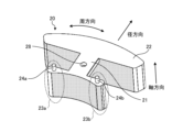
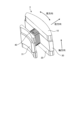
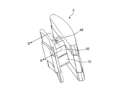
第2の実施形態におけるピース4は、第1インシュレータ10、第2インシュレータ20及びティース30が、金属部材60,70により覆われる点が、第1の実施形態におけるピース3と異なる。図7は、第2の実施形態におけるコイルが巻き回されたピースの一例を示す斜視図である。図8は、第2の実施形態におけるコイルが巻き回される前のピースを示す斜視図である。図7に示すように、本実施形態において、コイル40は、第1インシュレータ10、第2インシュレータ20及びティース30を覆う金属部材60,70の外側に接触するように巻き回される。
Claims (7)
- 回転軸と、
ロータと、
前記ロータに対向する磁極部と、
インシュレータと、
を備え、
前記磁極部は、周方向に突出した端部を2つ備え、
前記2つの端部に、前記インシュレータと嵌合する嵌合部が設けられ、
前記インシュレータには、前記2つの端部に直接又は他の部材を介して嵌合する被嵌合部が設けられ、
前記端部の径方向における厚さが、前記2つの端部の中間に位置する前記磁極部の一部分の径方向における厚さよりも大きい、
モータ。 - 前記インシュレータは、第1インシュレータ及び第2インシュレータを含み、
回転軸方向において、前記第1インシュレータ及び前記第2インシュレータの間に、前記磁極部が挟まれ、
前記磁極部には、前記第1インシュレータ及び前記第2インシュレータを介して、コイルが巻き回される、
請求項1に記載のモータ。 - 回転軸方向において、前記第1インシュレータ及び前記第2インシュレータの間には金属部材が配置されており、
前記金属部材と前記コイルとは接触している、
請求項2に記載のモータ。 - 前記金属部材には、絶縁膜が形成され、
前記コイルは、前記絶縁膜に接触している、
請求項3に記載のモータ。 - 前記嵌合部及び前記被嵌合部の一方が、回転軸方向に延在する凸部であり、
前記嵌合部及び前記被嵌合部の他方が、回転軸方向に形成された凹部又は孔部である、請求項1乃至4のいずれか1つに記載のモータ。 - 前記嵌合部及び前記被嵌合部が、回転軸方向に形成された凹部又は孔部であり、
前記他の部材を介して前記嵌合部と前記被嵌合部とが嵌合している、請求項1乃至4のいずれか1つに記載のモータ。 - 前記磁極部を含むヨークを備え、
前記ヨークは、前記磁極部を内周部として、外周部と、当該内周部と外周部とを連結する中間部と、を備え、
前記外周部は、径方向において前記磁極部の2つの端部と対向し、周方向に突出した2つの端部を備え、
径方向において対向する、前記磁極部の端部の面と、前記外周部の端部の面とが、周方向において、略平行に形成される、請求項1乃至6のいずれか1つに記載のモータ。
Priority Applications (1)
| Application Number | Priority Date | Filing Date | Title |
|---|---|---|---|
| JP2020152062A JP7561549B2 (ja) | 2020-09-10 | 2020-09-10 | モータ |
Applications Claiming Priority (1)
| Application Number | Priority Date | Filing Date | Title |
|---|---|---|---|
| JP2020152062A JP7561549B2 (ja) | 2020-09-10 | 2020-09-10 | モータ |
Publications (2)
| Publication Number | Publication Date |
|---|---|
| JP2022046152A JP2022046152A (ja) | 2022-03-23 |
| JP7561549B2 true JP7561549B2 (ja) | 2024-10-04 |
Family
ID=80847146
Family Applications (1)
| Application Number | Title | Priority Date | Filing Date |
|---|---|---|---|
| JP2020152062A Active JP7561549B2 (ja) | 2020-09-10 | 2020-09-10 | モータ |
Country Status (1)
| Country | Link |
|---|---|
| JP (1) | JP7561549B2 (ja) |
Citations (6)
| Publication number | Priority date | Publication date | Assignee | Title |
|---|---|---|---|---|
| JP2003111329A (ja) | 2001-10-03 | 2003-04-11 | Mitsubishi Electric Corp | 回転電機の固定子 |
| WO2005107038A1 (ja) | 2004-04-30 | 2005-11-10 | Sumitomo Electric Industries, Ltd. | 圧粉磁心およびその製造方法 |
| JP2008278632A (ja) | 2007-04-27 | 2008-11-13 | Sumitomo Electric Ind Ltd | 分割ステータおよび分割ステータの製造方法 |
| JP2017225208A (ja) | 2016-06-13 | 2017-12-21 | 三菱電機株式会社 | 電機子、回転電機および電機子の製造方法 |
| JP2018137941A (ja) | 2017-02-23 | 2018-08-30 | 三菱電機株式会社 | 回転電機のステータおよび回転電機のステータの製造方法 |
| JP2020036444A (ja) | 2018-08-29 | 2020-03-05 | 国立大学法人信州大学 | モータ |
-
2020
- 2020-09-10 JP JP2020152062A patent/JP7561549B2/ja active Active
Patent Citations (6)
| Publication number | Priority date | Publication date | Assignee | Title |
|---|---|---|---|---|
| JP2003111329A (ja) | 2001-10-03 | 2003-04-11 | Mitsubishi Electric Corp | 回転電機の固定子 |
| WO2005107038A1 (ja) | 2004-04-30 | 2005-11-10 | Sumitomo Electric Industries, Ltd. | 圧粉磁心およびその製造方法 |
| JP2008278632A (ja) | 2007-04-27 | 2008-11-13 | Sumitomo Electric Ind Ltd | 分割ステータおよび分割ステータの製造方法 |
| JP2017225208A (ja) | 2016-06-13 | 2017-12-21 | 三菱電機株式会社 | 電機子、回転電機および電機子の製造方法 |
| JP2018137941A (ja) | 2017-02-23 | 2018-08-30 | 三菱電機株式会社 | 回転電機のステータおよび回転電機のステータの製造方法 |
| JP2020036444A (ja) | 2018-08-29 | 2020-03-05 | 国立大学法人信州大学 | モータ |
Also Published As
| Publication number | Publication date |
|---|---|
| JP2022046152A (ja) | 2022-03-23 |
Similar Documents
| Publication | Publication Date | Title |
|---|---|---|
| US9966809B2 (en) | Motor | |
| US7323801B2 (en) | Axial air-gap electronic motor | |
| JP2013066314A (ja) | モータおよびモータの製造方法 | |
| JP6296116B2 (ja) | 回転電機 | |
| JP4365194B2 (ja) | 永久磁石電動機 | |
| JP4640373B2 (ja) | 回転電機 | |
| JP3430109B2 (ja) | 内転型電動機の固定子 | |
| JP2007159170A5 (ja) | ||
| JP2007159170A (ja) | 回転機 | |
| TWI673936B (zh) | 軸向間隙型旋轉電機 | |
| JP4002451B2 (ja) | 回転電機 | |
| US20110210638A1 (en) | Stator for electric rotating machine | |
| JP7211883B2 (ja) | ステータおよびモータ | |
| JP7561549B2 (ja) | モータ | |
| JP2013038858A (ja) | ロータ | |
| JP2022175072A (ja) | モータ | |
| JP3607977B2 (ja) | モールドモータ | |
| JP6429400B2 (ja) | ステータコア、ステータ及び回転電機 | |
| CN120419074A (zh) | 轴向磁通电机的定子 | |
| US11005333B2 (en) | Electric motor having a stator with a radially outside rotor with the rotor having a fan mounting portion comprising a noncontact region and a contract region configured to contact a mouting surface of a fan | |
| US20200099262A1 (en) | Polyphase claw pole motor | |
| JP7548018B2 (ja) | モータ | |
| CN118765476A (zh) | 定子和旋转电机 | |
| JP4032352B2 (ja) | 固定子および回転電機 | |
| JP2013005564A (ja) | ブラシレスモータ |
Legal Events
| Date | Code | Title | Description |
|---|---|---|---|
| A621 | Written request for application examination |
Free format text: JAPANESE INTERMEDIATE CODE: A621 Effective date: 20230824 |
|
| A977 | Report on retrieval |
Free format text: JAPANESE INTERMEDIATE CODE: A971007 Effective date: 20240215 |
|
| A131 | Notification of reasons for refusal |
Free format text: JAPANESE INTERMEDIATE CODE: A131 Effective date: 20240305 |
|
| A521 | Request for written amendment filed |
Free format text: JAPANESE INTERMEDIATE CODE: A523 Effective date: 20240501 |
|
| TRDD | Decision of grant or rejection written | ||
| A01 | Written decision to grant a patent or to grant a registration (utility model) |
Free format text: JAPANESE INTERMEDIATE CODE: A01 Effective date: 20240828 |
|
| A61 | First payment of annual fees (during grant procedure) |
Free format text: JAPANESE INTERMEDIATE CODE: A61 Effective date: 20240924 |
|
| R150 | Certificate of patent or registration of utility model |
Ref document number: 7561549 Country of ref document: JP Free format text: JAPANESE INTERMEDIATE CODE: R150 |