JP7468112B2 - INTERFACE CIRCUIT AND METHOD FOR CONTROLLING INTERFACE CIRCUIT - Patent application - Google Patents
INTERFACE CIRCUIT AND METHOD FOR CONTROLLING INTERFACE CIRCUIT - Patent application Download PDFInfo
- Publication number
- JP7468112B2 JP7468112B2 JP2020074713A JP2020074713A JP7468112B2 JP 7468112 B2 JP7468112 B2 JP 7468112B2 JP 2020074713 A JP2020074713 A JP 2020074713A JP 2020074713 A JP2020074713 A JP 2020074713A JP 7468112 B2 JP7468112 B2 JP 7468112B2
- Authority
- JP
- Japan
- Prior art keywords
- instruction
- memory
- unit
- request
- access
- Prior art date
- Legal status (The legal status is an assumption and is not a legal conclusion. Google has not performed a legal analysis and makes no representation as to the accuracy of the status listed.)
- Active
Links
- 238000000034 method Methods 0.000 title claims description 7
- 230000015654 memory Effects 0.000 claims description 83
- 230000004044 response Effects 0.000 claims description 18
- 238000012546 transfer Methods 0.000 claims description 6
- 238000010586 diagram Methods 0.000 description 48
- 239000000872 buffer Substances 0.000 description 15
- 230000007257 malfunction Effects 0.000 description 8
- 230000007704 transition Effects 0.000 description 5
- 230000006870 function Effects 0.000 description 4
- 230000009977 dual effect Effects 0.000 description 3
- 230000005764 inhibitory process Effects 0.000 description 2
- 238000012545 processing Methods 0.000 description 2
- 230000001960 triggered effect Effects 0.000 description 2
- 238000004891 communication Methods 0.000 description 1
- 230000007423 decrease Effects 0.000 description 1
- 230000000694 effects Effects 0.000 description 1
- RFHAOTPXVQNOHP-UHFFFAOYSA-N fluconazole Chemical compound C1=NC=NN1CC(C=1C(=CC(F)=CC=1)F)(O)CN1C=NC=N1 RFHAOTPXVQNOHP-UHFFFAOYSA-N 0.000 description 1
- 238000013507 mapping Methods 0.000 description 1
- 230000002093 peripheral effect Effects 0.000 description 1
Images


Description
本発明は、インタフェース回路およびインタフェース回路の制御方法に関する。 The present invention relates to an interface circuit and a method for controlling an interface circuit.
複数組のインタフェース回路とメモリチップとを同一パッケージ内に実装し、外部からの複数のチップセレクト信号のそれぞれに応じて、各インタフェース回路によりメモリチップをアクセス可能にするメモリシステムが開示されている(例えば、特許文献1参照)。この種のメモリシステムでは、シリアルインタフェースのメモリチップを使用することで、メモリチップおよびインタフェース回路を実装する実装基板の面積の増大が抑制される。 A memory system has been disclosed in which multiple sets of interface circuits and memory chips are mounted in the same package, and the memory chips can be accessed by each interface circuit in response to multiple chip select signals from the outside (see, for example, Patent Document 1). In this type of memory system, the use of a serial interface memory chip prevents the increase in the area of the mounting board on which the memory chips and interface circuits are mounted.
近時、SPI(Serial Peripheral Interface:登録商標)等のシリアルインタフェースは、1本の信号線を使用してデータを転送するシリアルモードと、複数の信号線を使用してデータを転送するパラレルモードとを有する。また、CPU(Central Processing Unit)等のプロセッサは、様々なインタフェースのシリアルメモリにアクセス可能にするために、インタフェース回路を介してシリアルメモリに接続される。そして、インタフェース回路は、設定レジスタの設定値の変更により、様々な仕様のシリアルメモリのアクセスを制御可能である。 Recently, serial interfaces such as SPI (Serial Peripheral Interface: registered trademark) have a serial mode in which data is transferred using one signal line, and a parallel mode in which data is transferred using multiple signal lines. A processor such as a CPU (Central Processing Unit) is connected to the serial memory via an interface circuit to enable access to serial memories of various interfaces. The interface circuit can control access to serial memories of various specifications by changing the setting value of a setting register.
この種のシリアルインタフェースを使用してシリアルメモリからプログラム等をリードするCPU(Central Processing Unit)等のプロセッサは、通常、パワーオン時にシリアルモードでプログラムのフェッチを開始する。このため、データ転送レートを高くし、シリアルメモリのアクセス効率を向上するためには、シリアルメモリの動作モードをシリアルモードからパラレルモードに切り替える必要がある。 Processors such as CPUs (Central Processing Units) that use this type of serial interface to read programs from serial memory usually start fetching programs in serial mode when powered on. For this reason, in order to increase the data transfer rate and improve the access efficiency of the serial memory, it is necessary to switch the operating mode of the serial memory from serial mode to parallel mode.
しかしながら、CPUがシリアルメモリからプログラムをフェッチしている最中に動作モードを変更すると、誤動作するおそれがある。誤動作を抑止するためには、例えば、シリアルメモリに格納されているプログラムをRAM等の他のメモリに転送し、他のメモリ上のプログラムをフェッチしている間に、シリアルメモリの動作モードが切り替えられる。この場合、プログラムのRAM等への転送中、シリアルメモリに対するプログラムのフェッチが実行されないため、フェッチ効率が低下する。 However, changing the operating mode while the CPU is fetching a program from the serial memory may result in malfunction. In order to prevent malfunction, for example, the program stored in the serial memory is transferred to another memory such as a RAM, and the operating mode of the serial memory is switched while the program in the other memory is being fetched. In this case, since the program is not fetched from the serial memory while it is being transferred to the RAM, etc., fetch efficiency decreases.
本発明は、上記の課題に鑑みてなされたものであり、シリアルメモリに対するアクセスを継続しつつ、シリアルメモリの動作モードを切り替えることを目的とする。 The present invention was made in consideration of the above problems, and aims to switch the operating mode of a serial memory while continuing to access the serial memory.
上記技術的課題を解決するため、本発明の一形態のインタフェース回路は、1本の信号線を使用してデータを転送するシリアルモードと複数の信号線を使用してデータを転送するパラレルモードとを切り替え可能なシリアルメモリのアクセスを制御するインタフェース回路であって、前記シリアルメモリに保持されたプログラムを実行するプロセッサから出力される前記シリアルメモリのアクセス用の命令を保持する第1命令保持部を含み、前記第1命令保持部に保持した命令を出力するインダイレクトアクセス用の第1インタフェース部と、前記プロセッサからのメモリアクセス要求を前記シリアルメモリが受け付け可能な命令に変換し、変換した命令を出力するメモリマップドアクセス用の第2インタフェース部と、前記第1インタフェース部または前記第2インタフェース部が出力する命令を前記シリアルメモリに出力し、前記第1インタフェース部からの命令の受信と前記第2インタフェース部からの命令の受信とが競合する場合、前記第2インタフェース部から受信する命令の出力を禁止する調停部と、を有し、前記第2インタフェース部は、前記変換した命令を保持する第2命令保持部と、前記第2命令保持部から前記変換した命令が転送される第3命令保持部と、を有し、前記第1インタフェース部は、前記第1命令保持部に保持された命令の出力に応答して前記第2命令保持部から前記第3命令保持部に前記変換した命令を転送する場合にセットされるシフトフラグを有する。
In order to solve the above technical problem, an interface circuit according to one aspect of the present invention is an interface circuit for controlling access to a serial memory that is switchable between a serial mode in which data is transferred using one signal line and a parallel mode in which data is transferred using a plurality of signal lines, the interface circuit including a first instruction holding unit that holds an instruction for accessing the serial memory output from a processor that executes a program held in the serial memory, a first interface unit for indirect access that outputs the instruction held in the first instruction holding unit, and a third interface unit for memory mapped access that converts a memory access request from the processor into an instruction acceptable to the serial memory and outputs the converted instruction. the serial memory, and an arbitration unit which outputs an instruction output by the first interface unit or the second interface unit to the serial memory and prohibits the output of the instruction received from the second interface unit when there is a conflict between receiving an instruction from the first interface unit and receiving an instruction from the second interface unit, the second interface unit having a second instruction holding unit which holds the converted instruction and a third instruction holding unit to which the converted instruction is transferred from the second instruction holding unit, and the first interface unit has a shift flag which is set when transferring the converted instruction from the second instruction holding unit to the third instruction holding unit in response to output of the instruction held in the first instruction holding unit.
シリアルメモリに対するアクセスを継続しつつ、シリアルメモリの動作モードを切り替えることすることができる。 It is possible to switch the operating mode of the serial memory while continuing to access the serial memory.
以下、図面を参照して実施の形態の説明を行う。なお、各図面において、同一構成部分には同一符号を付し、重複した説明を省略する場合がある。また、信号を示す符号を、端子または信号線を示す符号としても使用する。 The following describes the embodiments with reference to the drawings. Note that in each drawing, the same components are given the same reference numerals, and duplicate explanations may be omitted. Also, reference numerals indicating signals are used as reference numerals indicating terminals or signal lines.
(第1の実施形態)
図1は、本発明の第1の実施形態に係るSPIコントローラが搭載されるシステムの一例を示すブロック図である。特に限定されないが、図1に示すシステムSYSは、例えば、コピー機能、ファクシミリ機能、プリント機能またはスキャナ機能等を有するMFP(MultiFunction Printer)等の画像形成装置に含まれる。
First Embodiment
Fig. 1 is a block diagram showing an example of a system in which an SPI controller according to a first embodiment of the present invention is installed. Although not particularly limited, the system SYS shown in Fig. 1 is included in an image forming apparatus such as an MFP (Multifunction Printer) having a copy function, a facsimile function, a print function, a scanner function, etc.
システムSYSは、SoC(System on a Chip)100およびシリアルフラッシュメモリ等のシリアルROM200を有する。SoC100は、CPU300、デコーダ400、SPIコントローラ500、RAM(Random Access Memory)600、入出力インタフェース部700およびネットワークインタフェース部800を有する。シリアルROM200は、シリアルメモリの一例であり、SPIコントローラ500は、シリアルROM200のアクセスを制御するインタフェース回路の一例であり、CPU300は、プロセッサの一例である。
The system SYS has a SoC (System on a Chip) 100 and a
CPU300は、シリアルROM200に格納されたプログラムをフェッチすることで、動作し、SoC100内の動作の制御と、SoC100に接続される外部装置との通信等を制御する。CPU300は、クロック信号CLKおよびチップセレクト信号/CSをシリアルROM200に出力し、4ビットのデータ信号IO(IO0-IO3)をシリアルROM200に対して入出力する。CPU300からシリアルROM200に出力されるデータ信号IOは、データ信号だけではなく、コマンド信号(命令)またはアドレス信号の場合もある。4ビットのデータ信号IOのうち、何ビットを使用するかは、動作モードに応じて異なる。
The
なお、CPU300は、シリアルROM200が保持するプログラムをRAM600に展開することなく、シリアルROM200からリードしたプログラム(命令コードおよびオペランド)を直接実行する。プログラムのフェッチ効率を向上するため、例えば、CPU300は、一度フェッチしたプログラムを新しい順に保持する図示しないキャッシュメモリを有してもよい。
The
デコーダ400は、CPU300から出力されるアクセス要求に含まれるアドレスをデコードすることで、アクセス対象のデバイスを特定し、特定したデバイスにアクセスするためのセレクト信号を出力する。アクセス対象のデバイスは、シリアルROM200、RAM600、入出力インタフェース部700に接続される入出力デバイスまたはネットワークインタフェース部800に接続されるネットワークに接続される各種機器である。
The
SPIコントローラ500は、CPU300から出力されるシリアルROM200へのアクセス要求に基づいて、シリアルROM200のアクセスを制御し、例えば、シリアルROM200からプログラムまたはデータをリードする。SPIコントローラ500は、メモリマップドアクセスとインダイレクトアクセスと称するアクセスを実行可能である。
The
メモリマップドアクセスでは、CPU300が発行するリードアクセス要求(リードコマンド)が、SPIコントローラ500によりシリアルROM200のコマンド体系に自動的に変換される。そして、シリアルROM200からリードされたデータは、CPU300がリードコマンドを実行することなく、SPIコントローラ500からCPU300に直接出力される。従って、CPU300は、シリアルROM200のインタフェース仕様を意識することなく、シリアルROM200を、メモリマップ上に割り当てられたメモリとして、アクセスすることができる。例えば、メモリマップドアクセスは、リードアクセスのみに適用される。
In memory-mapped access, a read access request (read command) issued by the
インダイレクトアクセスでは、CPU300によりSPIコントローラ500内のレジスタにライトされた情報に基づいて、SPIコントローラ500がシリアルROM200にライトアクセスまたはリードアクセスする。例えば、インダイレクトアクセスによるライトアクセスは、シリアルROM200の動作モードを切り替えるために使用される。SPIコントローラ500の内部構成の例は、図5で説明する。
In indirect access, the
RAM600は、いわゆるワーキングRAMであり、SoC100の動作に必要な最小限の記憶容量を有する。入出力インタフェース部700は、システムSYSに接続される図示しない入出力装置との間で情報を入出力する。入出力インタフェース部700には、入力装置または出力装置が接続されてもよい。入出力インタフェース部700は、接続される装置毎に設けられてもよい。ネットワークインタフェース部800は、システムSYSに接続される図示しないネットワークを介して他の装置と通信を実行する。
シリアルROM200は、動作モードとして、例えば、シングルモード、デュアルモード、クワッドモード、クワッドパラレル命令モードおよび命令省略モードをサポートしている。シングルモードでは、命令およびアドレスがデータ端子IO0(DI)に入力され、リードデータがデータ端子IO1(DO)から直列に出力される。シングルモードは、1本の信号線(IO0またはIO1)を使用してデータを転送するシリアルモードの一例である。
The
デュアルモードでは、命令がデータ端子IO0に入力され、アドレスがデータ端子IO0、IO1に入力され、リードデータがデータ端子IO0、IO1から並列に出力される。クワッドモードでは、命令がデータ端子IO0に入力され、アドレスがデータ端子IO0~IO3に入力され、リードデータがデータ端子IO0~IO3から並列に出力される。 In dual mode, commands are input to data terminal IO0, addresses are input to data terminals IO0 and IO1, and read data is output in parallel from data terminals IO0 and IO1. In quad mode, commands are input to data terminal IO0, addresses are input to data terminals IO0 to IO3, and read data is output in parallel from data terminals IO0 to IO3.
クワッドパラレル命令モードでは、命令およびアドレスがデータ端子IO0~IO3に入力され、リードデータがデータ端子IO0~IO3から並列に出力される。命令省略モードは、命令の入力を省略する動作モードであり、命令省略モードにエンターする以前に入力された命令が引き継がれる。例えば、命令省略モードでは、アドレスがデータ端子IO0~IO3に入力され、リードデータがデータ端子IO0~IO3から並列に出力される。デュアルモード、クワッドモードおよび命令省略モードは、複数の信号線を使用してデータを転送するパラレルモードの一例である。 In the quad parallel instruction mode, instructions and addresses are input to data terminals IO0 to IO3, and read data is output in parallel from data terminals IO0 to IO3. The instruction omission mode is an operating mode in which the input of instructions is omitted, and instructions input before entering the instruction omission mode are carried over. For example, in the instruction omission mode, addresses are input to data terminals IO0 to IO3, and read data is output in parallel from data terminals IO0 to IO3. The dual mode, quad mode, and instruction omission mode are examples of parallel modes that transfer data using multiple signal lines.
他の動作モードからクワッドパラレル命令モードまたは命令省略モードへの切り替えは、切り替え命令を入力することで行われる。この場合、切り替え命令の入力に使用されるデータ端子IOのビット数は、現在の動作モードに依存する。以下では、クワッドパラレル命令モードは、QPIモードと称し、命令省略モードは、XIPモードと称する。 Switching from another operating mode to the quad-parallel instruction mode or the instruction omission mode is performed by inputting a switching command. In this case, the number of bits of the data terminal IO used to input the switching command depends on the current operating mode. In the following, the quad-parallel instruction mode is referred to as the QPI mode, and the instruction omission mode is referred to as the XIP mode.
図2は、図1のシリアルROM200のシングルモードでのリード動作の一例を示すタイミング図である。図2および以降のタイミング図において、網掛けはDon't Careを示す。シングルモードでは、チップセレクト信号/CSがロウレベルの期間に、クロック信号CLKに同期して、命令INSおよびアドレスADがシリアルROM200に入力され、シリアルROM200からリードデータRDTが出力される。命令INSおよびアドレスADは、データ端子IO0に入力され、リードデータRDTは、データ端子IO1から出力される。
Figure 2 is a timing diagram showing an example of a read operation in single mode of the
図2では、命令INSを03hとしているが、命令コードは03hに限定されない。命令コードの末尾の"h"は、その前の数値が16進数であることを示す。また、命令INS、アドレスAD、リードデータRDTのビット数(それぞれ8ビット、24ビット、32ビット(4バイト))も図示した以外でもよい。以降のタイミング図に示すビット数(バイト数)も同様である。シングルモードでのクロック信号CLKの周波数の上限は、50MHz程度である。クロック信号CLKの周波数は、QPIモードおよびXIPモードに比べて低いため、シングルモードでは、アドレスADとリードデータRDTとの間にダミーサイクルDMY(図3)を挿入しなくてもよい。 In FIG. 2, the command INS is 03h, but the command code is not limited to 03h. The "h" at the end of the command code indicates that the number preceding it is a hexadecimal number. The number of bits of the command INS, address AD, and read data RDT (8 bits, 24 bits, and 32 bits (4 bytes), respectively) may also be other than those shown in the figure. The same applies to the number of bits (bytes) shown in the subsequent timing diagrams. The upper limit of the frequency of the clock signal CLK in single mode is about 50 MHz. Since the frequency of the clock signal CLK is lower than in QPI mode and XIP mode, in single mode, it is not necessary to insert a dummy cycle DMY (FIG. 3) between the address AD and the read data RDT.
図3は、図1のシリアルROM200のQPIモードでのリード動作の一例を示すタイミング図である。チップセレクト信号/CSおよびクロック信号CLKの入力は、図2と同様である。QPIモードでは、4ビットのデータ端子IO0~IO3が使用される。そして、8ビットの命令INSが2クロックサイクルでシリアルROM200に入力され、24ビットのアドレスADが6クロックサイクルでシリアルROM200に入力される。
Figure 3 is a timing diagram showing an example of a read operation in QPI mode of the
アドレスADの入力後、8ビットのモードMDが2クロックサイクルでシリアルROM200に入力され、ダミーサイクルDMYが4クロックサイクル挿入された後、4バイトのリードデータRDTが8クロックサイクルで出力される。
After the address AD is input, an 8-bit mode MD is input to the
なお、QPIモードは、シングルモードと異なり、4ビットのデータ端子IO0~IO3を使用して命令をシリアルROM200に供給する。このため、QPIモードを使用するためには、シリアルROM200を予めQPIモードにエンターしておく必要がある。QPIモードへのエンターは、後述する図19に示すFast Read Quad I/O(Enter XIP mode)の命令コード(EBh)を38hとすることで実行される。
Note that unlike the single mode, the QPI mode uses 4-bit data terminals IO0 to IO3 to supply commands to the
図3において、命令INSのEBhは、XIPモードのエンターを示し、モードMDの入力値に応じて、次のチップセレクト信号/CSのアサートサイクルで、命令INSの入力が省略されるか否かが決定される。ダミーサイクルDMYを挿入することで、シリアルROM200内部でのリード動作をダミーサイクルDMYで隠すことができる。これにより、QPIモードでのクロック信号CLKの周波数の上限は、133MHz程度と、シングルモードに比べて高くなる。
In FIG. 3, the command INS EBh indicates the entry of XIP mode, and depending on the input value of mode MD, it is determined whether or not the input of command INS is omitted in the next assertion cycle of the chip select signal /CS. By inserting a dummy cycle DMY, the read operation inside the
図4は、図1のシリアルROM200のXIPモードでのリード動作の一例を示すタイミング図である。例えば、図4に示すXIPモードでのリード動作は、図3のQPIモードでのリード動作において、モードMDが命令INSの省略を示す場合に実行される。
Figure 4 is a timing diagram showing an example of a read operation in XIP mode of the
XIPモードでのリード動作は、QPIモードでのリード動作から命令INSが省略されることを除き、QPIモードと同様である。例えば、XIPモードにおいて、モードMDが命令INSの入力の省略を示す場合、次のチップセレクト信号/CSのアサートサイクルでもXIPモードのリード動作が実行される。一方、XIPモードにおいて、モードMDが命令INSの入力を示す場合、次のチップセレクト信号/CSのアサートサイクルでは、命令INSの入力を含むQPIモードのリード動作が実行される。 A read operation in XIP mode is similar to QPI mode, except that the INS command is omitted from a read operation in QPI mode. For example, in XIP mode, if mode MD indicates the omission of the INS command input, a XIP mode read operation is also executed at the next assert cycle of the chip select signal /CS. On the other hand, in XIP mode, if mode MD indicates the input of the INS command, a QPI mode read operation including the input of the INS command is executed at the next assert cycle of the chip select signal /CS.
図5は、図1のSPIコントローラ500の一例を示すブロック図である。SPIコントローラ500は、CPUインタフェース回路510、シーケンサ520、要求調停回路530およびプロトコル発生回路540を有する。CPUインタフェース回路510は、CPUバスを介して図1のCPU300に接続される。
Figure 5 is a block diagram showing an example of the
CPUインタフェース回路510は、例えば、CPUバスを介してCPU300から受信するリセット信号reset_nをシーケンサ520に出力する。シーケンサ520は、リセット信号reset_nのロウレベル期間にリセットされ、リセット信号reset_nのハイレベルへの変化によりリセットが解除され、動作を開始する。
The
シーケンサ520は、メモリマップドアクセス用の制御レジスタ群522と、インダイレクトアクセス用の制御レジスタ群525と、メモリマップドアクセスとインダイレクトアクセスとに共通の共通制御レジスタ528とを有する。制御レジスタ群522は、後述するPhase0~Phase5で使用される制御レジスタ523と、データバッファ524とを有する。制御レジスタ群525は、後述するPhase0~Phase5で使用される制御レジスタ526と、データバッファ527とを有する。
The
制御レジスタ523は、要求調停回路530に出力する命令を保持するカレント用のレジスタと、カレント用のレジスタに転送する命令を保持するネクスト用のレジスタとを有する。制御レジスタ526は、要求調停回路530に出力する命令を保持するカレント用のレジスタと、カレント用のレジスタに転送する命令を保持するネクスト用のレジスタとを有する。制御レジスタ523において、カレント用のレジスタは、第3命令保持部の一例であり、ネクスト用のレジスタは、第2命令保持部の一例である。制御レジスタ526において、カレント用のレジスタは、第1命令保持部の一例である。制御レジスタ群522、525および共通制御レジスタ528の仕様は、図6に示す。
The
シーケンサ520のうち、制御レジスタ群525と、制御レジスタ群525を使用してシリアルROM200のアクセスを制御する要素とは、第1インタフェース部の一例である。シーケンサ520のうち、制御レジスタ群522と、制御レジスタ群522を使用してシリアルROM200のアクセスを制御する要素は、第2インタフェース部の一例である。
Of the
シーケンサ520は、CPUインタフェース回路510を介してCPU300から受信するシリアルROM200のアクセス要求に基づいて、シリアルROM200に向けて命令INS等を出力し、シリアルROM200からリードデータRDT等を受信する。
The
要求調停回路530は、シーケンサ520から出力されるメモリマップドアクセス要求と、インダイレクトアクセス要求とを調停し、調停により選択した要求をプロトコル発生回路540に出力する。なお、要求調停回路530は、インダイレクトアクセス要求を受信した場合、メモリマップドアクセス要求の受付をマスクし、インダイレクトアクセス要求をプロトコル発生回路540に出力する。すなわち、要求調停回路530は、インダイレクトアクセス要求は、メモリマップドアクセス要求よりも優先して選択される。要求調停回路530は、調停部の一例である。
The
プロトコル発生回路540は、図1のシリアルROM200に接続される。プロトコル発生回路540は、要求調停回路530から受信するメモリマップドアクセス要求またはインダイレクトアクセス要求に基づいて、シリアルROM200のインタフェース仕様に応じた信号を生成し、生成した信号をシリアルROM200に出力する。そして、CPU300が発行するアクセス要求に基づいて、シーケンサ520の制御によりシリアルROM200がアクセスされる。
The
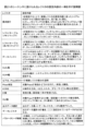
図6は、図5のシーケンサ520に設けられるレジスタの設定内容の一例を示す説明図である。要求発行レジスタは、メモリマップドアクセス用の制御レジスタ群522と、インダイレクトアクセス用の制御レジスタ群525とにそれぞれ設けられる。シーケンサ520は、要求発行レジスタが"1"に設定された場合、制御レジスタ523(または、526)の設定内容に従ったアクセス要求を要求調停回路530に発行する。シーケンサ520は、アクセス要求を要求調停回路530に発行後、要求発行レジスタを"0"に戻す。
Figure 6 is an explanatory diagram showing an example of the settings of registers provided in
なお、メモリマップドアクセスでは、シーケンサ520は、CPU300からのアクセス要求に含まれる情報に応じて、制御レジスタ523にシリアルROM200のアクセス用の情報を設定した後、制御レジスタ群522の要求発行レジスタに"1"をセットする。インダイレクトアクセスでは、制御レジスタ群525の要求発行レジスタは、CPU300が実行するプログラムにより"1"に設定される。要求発行レジスタは、要求発行フラグの一例である。
In addition, in memory-mapped access, the
制御レジスタ群522に含まれるシフトイネーブルレジスタ(メモリマップド)は、CPU300により設定される。シーケンサ520は、シフトイネーブルレジスタ(メモリマップド)が"1"の場合、インダイレクトアクセスの実行に応答して、メモリマップド用の制御レジスタ523のネクスト用のレジスタの内容を、カレント用のレジスタにコピーする。シフトイネーブルレジスタ(メモリマップド)は、制御レジスタ526のカレント用からの命令の出力に応答して、制御レジスタ523のネクスト用からカレント用に命令を転送する場合にセットされるシフトフラグの一例である。
The shift enable register (memory mapped) included in the
制御レジスタ群525に含まれるシフトイネーブルレジスタ(インダイレクト)は、CPU300により設定される。シーケンサ520は、シフトイネーブルレジスタ(インダイレクト)が"1"の場合、インダイレクトアクセスの実行に応答して、インダイレクト用の制御レジスタ526のネクスト用のレジスタの内容を、カレント用のレジスタにコピーする。
The shift enable register (indirect) included in the
メモリマップドアクセス用の制御レジスタ群522に含まれるデータバッファ524は、シリアルROM200からリードされるリードデータを一時的に蓄積するために使用される。シーケンサ520は、データバッファ524に蓄積したリードデータを、CPU300からのリード要求を受けることなく、CPU300のデータバス幅に合わせてCPU300に出力する。
The
インダイレクトアクセス用の制御レジスタ群525に含まれるデータバッファ527は、シリアルROM200からリードされるリードデータを蓄積するために使用される。シーケンサ520は、データバッファ527に蓄積したリードデータを、CPU300からのリード要求(ロード命令)に応じて取り出し、取り出したリードデータをCPU300に出力する。すなわち、インダイレクトアクセス用の制御レジスタ群525に保持されたリードデータは、CPU300により明示的にリードされる必要がある。
The
CLKL幅レジスタには、シリアルROM200に供給するクロック信号CLKのロウレベル期間を、例えば、SoC100で使用するシステムクロックの何クロック分にするかが設定される。CLKH幅レジスタは、クロック信号CLKのハイレベル期間を、システムクロックの何クロック分にするかが設定される。 The CLKL width register is set to, for example, how many clocks of the system clock used by SoC100 the low level period of the clock signal CLK supplied to serial ROM200 should be. The CLKH width register is set to, for example, how many clocks of the system clock the high level period of the clock signal CLK should be.
制御レジスタ群522、525の各PhaseN(N=0~4)の制御レジスタ523、526の構成は、互いに同じである。また、各制御レジスタ523、526のカレント用とネクスト用のレジスタの構成は、互いに同じである。
The configurations of the control registers 523, 526 for each PhaseN (N=0 to 4) of the
Phase有効レジスタは、"1"の場合、当該Phaseが有効であることを示し、"0"の場合、当該Phaseが無効であることを示す。IO方向レジスタは、"1"の場合、データ信号IOのシリアルROM200への出力を示し、"0"の場合、データ信号IOのシリアルROM200からの入力を示す。なお、図3および図4に示したダミーサイクルDMYのPhaseでは、Phase有効レジスタは、入力でも出力でもない"2"に設定される。
When the Phase validity register is "1", it indicates that the corresponding Phase is valid, and when it is "0", it indicates that the corresponding Phase is invalid. When the IO direction register is "1", it indicates that the data signal IO is output to the
IO数レジスタには、有効なデータ端子IOの数より"1"少ない数が設定される。IO数レジスタは、"0"の場合、1ビットが有効であり、"1"の場合、2ビットが有効であり、"3"のとき、4ビットが有効である。 The IO number register is set to a number "1" less than the number of valid data terminal IOs. When the IO number register is "0", 1 bit is valid, when it is "1", 2 bits are valid, and when it is "3", 4 bits are valid.
CLK数レジスタには、当該Phaseで使用するクロック信号CLKのクロックサイクル数より"1"少ない数が設定される。例えば、CLK数レジスタが"7"のPhaseは、8クロックサイクルを使用することを示し、CLK数レジスタが"23"のPhaseは、24クロックサイクルを使用することを示す。 The CLK number register is set to a number that is "1" less than the number of clock cycles of the clock signal CLK used in that phase. For example, a phase with a CLK number register of "7" indicates that 8 clock cycles are used, and a phase with a CLK number register of "23" indicates that 24 clock cycles are used.
出力データ選択レジスタは、"0"の場合、データレジスタに保持されたデータをデータ端子IOに出力することを示し、"1"の場合、CPU300からのアクセス要求に含まれるデータをデータ端子IOに出力することを示す。データレジスタは、出力データ選択レジスタが"0"の場合に有効になり、データレジスタに保持されているデータが出力される。
When the output data selection register is "0", it indicates that the data held in the data register is to be output to the data terminal IO, and when it is "1", it indicates that the data included in the access request from the
図7は、図5のシーケンサ520と要求調停回路530間で授受される信号の一例を示す説明図である。図8は、図5の要求調停回路530とプロトコル発生回路540間で授受される信号の一例を示す説明図である。
Figure 7 is an explanatory diagram showing an example of a signal exchanged between the
図9は、図5のプロトコル発生回路540の動作の一例を示すタイミング図である。図9の信号名の後ろに示す(I)は、入力信号を示し、(O)は、出力信号を示し、(I/O)は、入出力信号を示す。図10は、図9のタイミング図において各レジスタに設定される値の一例を示す説明図である。プロトコル発生回路540は、図10に示すように、Phase0~Phase4の5セット分の制御パラメータ値を受信し、その制御パラメータに従ってシーケンサとして動作する。
Figure 9 is a timing diagram showing an example of the operation of the
図9の(1)において、要求発行信号ACC_REQが論理値1となることでアクセス要求が発行される。この時、パラメータ信号ACC_PARAMは、アクセス要求のパラメータの設定値に確定される。 In FIG. 9 (1), an access request is issued when the request issuance signal ACC_REQ becomes logical 1. At this time, the parameter signal ACC_PARAM is set to the setting value of the parameter of the access request.
(2)において、プロトコル発生回路540は、要求発行信号ACC_REQの論理値1を検知する。この時、ビジー信号ACC_BUSYは論理値0であり、シリアルROM200へのアクセスが可能な状態である。このため、プロトコル発生回路540は、要求許可信号ACC_ACKを論理値1にアサートするとともに、チップセレクト信号/CSを論理値0にアサートし、シリアルROM200へのアクセスを開始する。
At (2), the
プロトコル発生回路540は、最初にPhase0用のパラメータを使用してシリアルROM200へのアクセスを開始する。CLKL幅およびCLKH幅は、1システムクロック(1SYSCLK)を示す値に設定されている。このため、SPIコントローラ500は、システムクロックSYSCLKを2分周したクロック信号CLKを生成する。
The
Phase0では、1本のデータ端子IOを使用して、データレジスタに設定されているEBhを8クロックサイクルで出力する設定となっている。このため、プロトコル発生回路540は、(11)の期間まで、Fast Read Quad I/O命令を示す03hをシリアルROM200に直列に出力する。
In
(11)から(17)までは、Phase1であり、Phase1の設定値に従ってFast Read Quad I/O命令でのアドレスの出力が行われる。なお、メモリマップドアクセスの場合、CPU300からのアクセス要求に含まれるアドレスが使用されるため、出力データ選択レジスタは論理値1に設定される。インダイレクトアクセスの場合、データレジスタ設定の値がアドレスとして使用されるため、出力データ選択レジスタは、論理値0に設定される。
(11) to (17) are
(17)~(19)までがPhase2であり、Fast Read Quad I/O命令でのモードの論理値がシリアルROM200に出力される。(19)~(23)までがPhase3であり、Fast Read Quad I/O命令でのダミーサイクルDMYに相当する。ダミーサイクルDMYのクロックサイクル数は、シリアルROM200のインタフェース仕様に合わせて設定される。ダミーサイクルDMYにより、命令(アドレス)をシリアルROM200に出力してからリードデータが出力されるまでの待ち時間が確保される。
(17) to (19) are
(23)~(31)までがPhase4であり、Fast Read Quad I/O命令において、シリアルROM200からデータが出力される期間である。プロトコル発生回路540は、シリアルROM200から受信したデータを、(25)~(33)の期間、リードデータ信号ACC_RDとして要求調停回路530を介してシーケンサ520に出力する。また、プロトコル発生回路540は、リードデータ信号ACC_RDによるデータの出力期間に、リードデータ有効信号ACC_RDRDYを論理値1にアサートする。そして、シリアルROM200からリードされたデータは、要求調停回路530を経由して、シーケンサ520のデータバッファ524、527のいずれかに蓄積される。
(23) to (31) are
図9に示すPhase1~Phase4によるシリアルROM200のアクセスの完了後、チップセレクト信号/CSがハイレベルにネゲートされる。例えば、チップセレクト信号/CSは、最終Phase4の終了後、クロック信号CLKの1クロックサイクル(1CLKL幅+1CLKH幅)後にネゲートされる。
After the access to the
図11は、図5の要求調停回路530の動作の一例を示すタイミング図である。図9と同様に、信号名の後ろに示す(I)は、入力信号を示し、信号名の後ろに示す(O)は、出力信号を示す。また、レジスタ名と同じ名称の信号は、レジスタの設定値と同じ論理値に設定される。
Figure 11 is a timing diagram showing an example of the operation of the
まず、(1)において、要求調停回路530は、論理値1にアサートされた要求発行信号MMA_REQをシーケンサ520から受信し、メモリマップドアクセス要求の発生を検出する。また、要求調停回路530は、論理値1にアサートされた要求発行信号IDA_REQをシーケンサ520から受信し、インダイレクトアクセス要求の発生を検出する。すなわち、要求調停回路530は、メモップドアクセス要求とインダイレクトアクセス要求とが同時に発生したことを検出する。
First, in (1), the
(2)において、要求調停回路530は、メモリマップドアクセス要求よりもインダイレクトアクセス要求を優先して調停する。これにより、インダイレクトアクセス要求によるシリアルROM200のアクセス中、メモリマップドアクセス要求によるシリアルROM200のアクセスは禁止される。
In (2), the
インダイレクトアクセス要求によるアクセスを決定した要求調停回路530は、論理値1にアサートした要求許可信号IDA_ACKをシーケンサ520に出力する。また、要求調停回路530は、シーケンサ520から受信したパラメータ信号IDA_PARAMの内容(IDP_P0)をパラメータ信号ACC_PARAMとしてプロトコル発生回路540に出力する。同時に、要求調停回路530は、論理値1にアサートした要求発行信号ACC_REQをプロトコル発生回路540に出力する。
The
なお、(2)では、要求調停回路530は、論理値1にアサートしたシフト要求信号IDA_NEXTをシーケンサ520に出力し、インダイレクトアクセス要求に対し、ネクストのパラメータをカレントにシフトすることを要求する。これは、シーケンサ520から受信するシフトイネーブル信号IDA_SHIFTが論理値1にアサートされており、かつ、インダイレクトアクセス要求が許可されたためである。論理値1のシフトイネーブル信号IDA_SHIFTは、インダイレクトアクセス要求によるシリアルROM200のアクセス実行に基づいて、インダイレクト用の制御レジスタ526のネクスト用の内容をカレント用にコピーする要求を示す。
In (2), the
(3)において、要求調停回路530は、論理値1にアサートされた要求許可信号ACC_ACKとビジー信号ACC_BUSYとをプロトコル発生回路から受信する。また、要求調停回路530は、パラメータ信号IDA_PARAMの内容(IDP_P1)をシーケンサ520から受信する。
In (3), the
(6)~(8)の期間において、要求調停回路530は、プロトコル発生回路540を介してシリアルROM200からのリードデータ(RD_IO0、RD_IO1)をリードデータ信号ACC_RDとして受信する。要求調停回路530は、論理値1にアサートされたリードデータ有効信号ACC_RDRDYにより、リードデータ信号ACC_RDが有効なデータであることを検出する。
During periods (6) to (8), the
要求調停回路530は、受信したリードデータ(RD_IO0、RD_IO1)を、(7)~(9)の期間に、リードデータ信号IDA_RDとしてシーケンサ520に出力する。要求調停回路530は、有効なリードデータ信号IDA_RDを出力している期間、リードデータ有効信号IDA_RDRDYを論理値1にアサートする。リードデータ(RD_IO0、RD_IO1)は、シーケンサ520のインダイレクト用のデータバッファ527に格納される。
The
(9)において、要求調停回路530は、プロトコル発生回路540からのビジー信号ACC_BUSYのネゲート(論理値0)を検知する。また、要求調停回路530は、このタイミングで、要求発行信号MMA_REQと要求発行信号IDA_REQが共にアサートされていることを検知する。要求調停回路530は、インダイレクトアクセス要求を優先して調停するため、(9)において、要求許可信号IDA_ACKをアサートする。
At (9), the
また、要求調停回路530は、(3)で受信したパラメータ信号IDA_PARAMの内容(IDP_P1)をパラメータ信号ACC_PARAMとしてプロトコル発生回路540に出力し、同時に、要求発行信号ACC_REQをアサートする。これを受け、(10)において、要求調停回路530は、プロトコル発生回路540からアサートされた要求許可信号ACC_ACKとビジー信号ACC_BUSYとを受信する。
The
また、(10)では、要求調停回路530は、論理値1にアサートしたシフト要求信号MMA_NEXTをシーケンサ520に出力し、メモリマップドアクセス用の制御レジスタ523のネクスト用のパラメータをカレント用にシフトすることを要求する。これは、シーケンサ520から受信するシフトイネーブル信号MMA_SHIFTが論理値1にアサートされており、かつ、インダイレクトアクセス要求が許可されたためである。論理値1のシフトイネーブル信号MMA_SHIFTは、インダイレクトアクセス要求によるシリアルROM200のアクセス実行に基づいて、メモリマップド用の制御レジスタ523のネクスト用の内容をカレント用にコピーする要求を示す。
In addition, in (10), the
次に、(13)において、要求調停回路530は、プロトコル発生回路540からのビジー信号ACC_BUSYのネゲートを検知する。また、要求調停回路530は、シーケンサ520からの要求発行信号MMA_REQのみのアサートを検知する。この結果、要求調停回路530は、論理値1にアサートした要求許可信号MMA_ACKをプロトコル発生回路540に出力する。
Next, in (13), the
また、要求調停回路530は、パラメータ信号IDA_PARAMの内容(MMA_P1)をパラメータ信号ACC_PARAMとしてプロトコル発生回路540に出力し、同時に、要求発行信号ACC_REQをアサートする。これを受け、(15)において、要求調停回路530は、プロトコル発生回路540からアサートされた要求許可信号ACC_ACKとビジー信号ACC_BUSYとを受信する。そして、要求調停回路530は、(16)~(18)において、プロトコル発生回路540を介して、シリアルROM200からのリードデータDR_M10、RD_M11を受信する。
The
図12は、図1のSPIコントローラ500がシリアルROM200をシングルモードからXIPモードに切り替える動作の一例を示すフロー図である。図12は、SPIコントローラ500の制御方法の一例を示す。XIPモードへの切り替えは、CPU300によるシーケンサ520内の制御レジスタ群522、525へのパラメータのライトに基づいて、シーケンサ520により実行される。
Figure 12 is a flow diagram showing an example of the operation of the
まず、ステップS10において、CPU300からのライト命令に基づいて、メモリマップドアクセス用の制御レジスタ523のネクスト用に、XIPモードでシリアルROM200からデータをリードするためのパラメータが設定される(Fast Read Quad I/O(XIP))。メモリマップドアクセス用の制御レジスタ523のネクスト用に設定されるパラメータは、XIPモードへのエンター後に最初に実行される命令で使用される。
First, in step S10, based on a write command from the
次に、ステップS12において、CPU300からのライト命令に基づいて、インダイレクトアクセス用の制御レジスタ526のカレント用に、XIPモードにエンターするためのパラメータが設定される(Fast Read Quad I/O(XIP遷移))。例えば、XIPモードへのエンターは、クワッドモードによりシリアルROM200からリードデータをリードするアクセスとともに実施される。
Next, in step S12, based on a write command from
次に、ステップS14において、CPU300からのライト命令に基づいて、シフトイネーブルレジスタ(メモリマップド)に"1"が設定される。次に、ステップS16において、CPU300からのライト命令に基づいて、インダイレクトアクセス用の要求発行レジスタに"1"が設定される。
Next, in step S14, a "1" is set in the shift enable register (memory mapped) based on a write command from
次に、ステップS18において、シーケンサ520は、ステップS16に基づいて、XIPモードに切り替えるためのリードアクセス要求をシリアルROM200に発行する。そして、シーケンサ520は、XIPモードに切り替えるためのリードアクセス要求に基づいて、シリアルROM200から出力されるリードデータをデータレジスタに格納し、インダイレクトアクセス用の要求発行レジスタを"0"にリセットする。これにより、XIPモードに切り替える動作が完了する。図12に示す動作の完了後、図4に示したXIPモードでのリード動作が繰り返し実行されることで、シリアルROM200からのプログラムのリード効率が向上する。
Next, in step S18, the
図13は、図12のフローを実行する場合のメモリマップド用のカレント用制御レジスタの設定例を示す説明図である。なお、図13に示すメモリマップド用のカレント用制御レジスタは、デフォルト値として設定されている。図13は、図12のフローによる各種レジスタへのパラメータの設定と並行してシングルモードでのリード動作(ノーマルリード)を実行するために、メモリマップド用のカレント用制御レジスタに設定されるパラメータの例を示す。なお、図13に示すレジスタの状態は、シリアルROM200がシングルモードに設定されている場合に、CPU300からのリードアクセス要求に応じて、シーケンサ520により設定する。
Figure 13 is an explanatory diagram showing an example of the settings of the memory-mapped current control register when executing the flow of Figure 12. The memory-mapped current control register shown in Figure 13 is set as a default value. Figure 13 shows an example of parameters set in the memory-mapped current control register to execute a read operation (normal read) in single mode in parallel with the setting of parameters in various registers according to the flow of Figure 12. The state of the register shown in Figure 13 is set by the
図13に示す状態でシリアルROM200に対して実行されるリード動作では、シーケンサ520は、Phase0~2のレジスタに設定された情報に従って、命令とアドレスをシリアルROM200に出力し、シリアルROM200からリードデータを受信する。そして、図2に示したリード動作が実行される。メモリマップドアクセスでは、シーケンサ520は、シリアルROM200から受信してデータバッファ524に格納したデータを、リードアクセス要求の応答としてCPU300に向けて出力する。
In a read operation performed on the
図14は、図12のフローを実行する場合のメモリマップド用のネクスト用制御レジスタの設定例を示す説明図である。図14は、図12のステップS10を実行後のメモリマップドアクセス用の制御レジスタ523のネクスト用の状態を示す。図14に示す状態でシリアルROM200に対して実行されるリード動作の例は、図4に示される。
Figure 14 is an explanatory diagram showing an example of the setting of the memory-mapped next control register when executing the flow of Figure 12. Figure 14 shows the next state of the memory-mapped
図15は、図12のフローを実行する場合のインダイレクト用のカレント用制御レジスタの設定例を示す説明図である。図15は、図12のステップS12の実行後のインダイレクトアクセス用の制御レジスタ526のカレント用の状態を示し、シリアルROM200をシングルモードからXIPモードに遷移する場合に設定される。
Figure 15 is an explanatory diagram showing an example of the setting of the current control register for indirect access when executing the flow of Figure 12. Figure 15 shows the current state of the
図16は、図12のフローを実行する場合のインダイレクト用のネクスト用制御レジスタの設定例を示す説明図である。例えば、インダイレクトアクセス用の制御レジスタ526のネクスト用は、シングルモードからXIPモードへの切り替え時に使用されない。この場合、シーケンサ520は、各レジスタのパラメータを、"0"(無効)または"Don't Care"に維持または設定する。
Figure 16 is an explanatory diagram showing an example of the settings of the indirect next control register when executing the flow of Figure 12. For example, the next control register 526 for indirect access is not used when switching from single mode to XIP mode. In this case, the
図17は、シリアルROM200をシングルモードからXIPモードに遷移させる図5のSPIコントローラ500の動作の一例を示すタイミング図である。図2と同様の動作については、詳細な説明は省略する。図17~図20に示す動作は、SPIコントローラ500の制御方法の一例を示す。
Figure 17 is a timing diagram showing an example of the operation of the
図17に示す動作は、図13に示したパラメータ設定に基づいて、シーケンサ520の制御により実行される。まず、(1)において、リセット信号reset_nが論理値1に解除され、SPIコントローラ500は動作を開始する。以降、リセット信号reset_nはハイレベル"H"に維持される。CPU300は、CPUアクセスに示すように、自分自身の動作のための命令をフェッチするために、メモリマップドアクセス要求(リード要求)を発行する。なお、リセット信号reset_nの解除の直後、シリアルROM200は、シングルモードに設定されている。
The operation shown in FIG. 17 is executed under the control of the
次に、(2)において、要求調停回路530のステータスは、ロウレベル"L"である。このため、SPIコントローラ500は、CPU300からのメモリマップドアクセス要求により、メモリマップド用の制御レジスタ523の設定値を使用してシングルモードでのリード動作を実行する。ここで、要求調停回路530のステータスを示す要求調停回路ステータスのロウレベル"L"は、インダイレクトアクセス要求が発生しておらず、メモリマップドアクセス要求を禁止していない状態を示す。
Next, in (2), the status of the
メモリマップドアクセス要求に応答するシングルモードでのシリアルROM200のリード動作は、(2)~(3)で実行され、シリアルROM200からリードされたリードデータRDTがCPU300に返されて、リード動作が完了する。
The read operation of the
CPU300は、後続の命令フェッチのために、(4)でメモリマップドアクセス要求(リード)を発行する。SPIコントローラ500は、このメモリマップドアクセス要求を(5)で許可し、(5)~(6)において、(2)~(3)と同様に、シングルモードでのリード動作が実行される。
The
次に、図18において、CPU300は、メモリマップド用の制御レジスタ523のネクスト用の設定のためのアクセス要求を発行する。アクセス要求に基づいてシリアルROM200からリードされたメモリマップドアクセス用の各種パラメータは、(7)で、制御レジスタ523のネクスト用に設定される。メモリマップドのネクスト用のパラメータは、XIPモードに切り替わった直後に実行されるXIPモードでのメモリアクセス要求(リード;Fast Read Quad I/O(XIP))である。
Next, in FIG. 18, the
この実施形態では、メモリマップド用の制御レジスタ523のカレント用を使用して、シングルモードでのシリアルROM200のアクセス(プログラムのフェッチ)を実行しながら、XIPモードの命令をネクスト用に予め格納することができる。また、ネクスト用のレジスタからカレント用のレジスタへの命令の転送は、シフトイネーブルレジスタ(メモリマップド)がセットされている場合に、インダイレクト用の制御レジスタ526のカレント用からの命令の出力に基づいて実行される。この結果、図18および図19に示すように、インダイレクトアクセス用の制御レジスタ526のカレントを使用してシリアルROM200をXIPモードに切り替え後、XIPモードの命令を迅速に実行することができる。
In this embodiment, the current register of the memory-mapped
CPU300は、(7)で、インダイレクト用の制御レジスタ526のカレント用の設定のためのアクセス要求を発行する。アクセス要求に基づいてシリアルROM200からリードされたインダイレクトアクセス用の各種パラメータは、(8)で、制御レジスタ526のカレント用に設定される。インダイレクトのカレント用のパラメータは、XIPモードにエンターするためのメモリアクセス要求(リード;Fast Read Quad I/O(Enter XIP mode))である。
At (7), the
この実施形態では、メモリマップドアクセス用の制御レジスタ523と、インダイレクトアクセス用の制御レジスタ526とが、互いに独立して設けられる。これにより、制御レジスタ526を使用してXIPモードに切り替わる前に、制御レジスタ526にXIPモード用の命令を予め格納しておくことができる。換言すれば、シリアルROM200をXIPモードに切り替える命令と、切り替え後に実行するXIPモードの命令とを、同時に保持することができる。
In this embodiment, the
この後、CPU300は、後続の命令フェッチのために、メモリマップドアクセス要求(リード)を発行する。SPIコントローラ500は、このメモリマップドアクセス要求を(9)で許可し、(9)~(10)において、図17と同様に、シングルモードでのリード動作が実行される。(10)において、CPU300は、シフトイネーブルレジスタ(メモリマップド)に"1"を設定する要求を発行し、シフトイネーブルレジスタ(メモリマップド)は、"1"に設定される。
Then, the
図19の(11)において、CPU300は、インダイレクト用の要求発行レジスタに"1"を設定するアクセス要求を発行する。インダイレクト用の要求発行レジスタは、(12)で"1"に設定される。シーケンサ520は、インダイレクト用の要求発行レジスタの"1"に応答して、制御レジスタ526のカレント用に保持している命令を含むパラメータを要求調停回路530に出力する。要求発行レジスタは、インダイレクトアクセス用とメモリマップドアクセス用とのそれぞれに対応して設けられる。これにより、制御レジスタ526、523毎に保持されるアクセス要求を、CPU300が実行するプログラムの任意の位置で、要求調停回路530を介してシリアルROM200に発行することができる。
In (11) of FIG. 19, the
要求調停回路530は、インダイレクトアクセス用の命令の受信に基づいて、メモリマップドアクセス用の命令の選択を禁止し、要求調停回路ステータスをハイレベル"H"に設定する。換言すれば、要求調停回路530は、インダイレクトアクセス用の命令の受信とメモリマップドアクセス用の命令の受信とが競合する場合、メモリマップドアクセス用の命令のシリアルROM200への出力を禁止する。
The
ここで、ハイレベル"H"の要求調停回路ステータスは、インダイレクトアクセス要求が発生していて、メモリマップドアクセス要求が禁止されている状態を示す。要求調停回路ステータスは、要求調停回路530の内部情報であるが、メモリマップドアクセス用の命令の選択の抑止を示す抑止信号として、要求調停回路530の外部に出力されてもよい。
Here, a high level "H" request arbitration circuit status indicates that an indirect access request has occurred and memory-mapped access requests are prohibited. The request arbitration circuit status is internal information of the
要求調停回路530の調停制御により、例えば、制御レジスタ523に保持されたXIPモードの命令が、制御レジスタ526に保持されたXIPモードへの切り替え命令より前に実行されることを抑止することができる。従って、シリアルROM200の動作モードを切り替える場合に、シリアルROM200の動作モードと、シリアルROM200に供給される命令の動作モードが不一致になることを抑止することができ、シリアルROM200の誤動作を抑止することができる。この結果、システムSYSの誤動作を抑止することができる。
The arbitration control of the
要求調停回路530は、調停により選択したインダイレクトアクセス要求(XIPモードにエンターする命令)をシリアルROM200に出力し、インダイレクトアクセス要求の発行をシーケンサ520に通知する。シフトイネーブルレジスタ(メモリマップド)は、図18の(10)で"1"に設定されている。このため、シーケンサ520は、インダイレクトアクセス要求の発行の通知に基づいて、(13)でメモリマップド用の制御レジスタ(ネクスト用)の内容をメモリマップド用の制御レジスタ(カレント用)にコピーする。
The
シフトイネーブルレジスタ(メモリマップド)を設けることで、インダイレクトアクセス要求の発行に応答して、その後に発行されるメモリマップドアクセス要求を、メモリマップドアクセス用の制御レジスタ523のカレント用に設定することができる。従って、例えば、インダイレクトアクセス要求でのXIPモードの切り替え後に、メモリマップドアクセス要求でのXIPモードの命令を実行することができる。
By providing a shift enable register (memory mapped), in response to the issuance of an indirect access request, the memory mapped access request issued thereafter can be set as the current one in the
これに対して、インダイレクトアクセス要求でのXIPモードの切り替えタイミングが、要求調停回路530による調停順により、連続する複数のメモリマップドアクセス要求のどこの間に挿入されるか分からないと、次に示すような不具合が発生する。例えば、連続するシングルモードでのメモリマップドアクセス要求の間に、XIPモードの切り替え命令が挿入された場合、XIPモードへの切り替え後のシングルモードでのアクセス要求は正常に実行されない。また、連続するXIPモードでのメモリマップドアクセス要求の間に、XIPモードの切り替え命令が挿入された場合、XIPモードへの切り替え前のXIPモードでのアクセス要求は正常に実行されない。
On the other hand, if it is not clear where in a sequence of multiple consecutive memory-mapped access requests the XIP mode switch command for an indirect access request will be inserted due to the arbitration order by the
(14)~(15)で、シリアルROM200をXIPモードにエンターさせるFast Read Quad I/O(Enter XIP mode)のアクセスが実行され、シリアルROM200の動作モードは、シングルモードからXIPモードに切り替わる。要求調停回路530は、インダイレクトアクセス要求によるシリアルROM200のアクセスが完了した(16)で、要求調停回路ステータスをロウレベル"L"に戻す。これにより、メモリマップドアクセス要求のシリアルROM200への出力の禁止状態を解除する。メモリマップドアクセス要求の出力禁止の契機となったインダイレクトアクセス要求によるシリアルROM200へのアクセスが完了するまで、メモリマップドアクセス要求の選択を禁止することで、SPIコントローラ500の誤動作を抑止することができる。また、XIPモードに切り替わった後、メモリマップドアクセス要求によりシリアルROM200がアクセスされるまでの待ち時間を最小限にすることができる。
In (14) to (15), a Fast Read Quad I/O (Enter XIP mode) access is executed to enter the
図20において、CPU300は、後続の命令フェッチのために、(17)でメモリマップドアクセス要求(リード)を発行する。SPIコントローラ500は、このメモリマップドアクセス要求を(18)で許可する。この時点で、メモリマップド用の制御レジスタ(カレント用)に、Fast Read Quad I/O(XIP mode)用のパラメータが設定されている。このため、SPIコントローラ500は、(18)~(19)において、命令コードを発行することなく、XIPモードでシリアルROM200のリード動作を実行する。そして、シリアルROM200からリードされたリードデータRDTがCPU300に返されて、XIPモードでのリード動作が完了する。
In FIG. 20, the
なお、図17のリセット信号reset_nの解除前に、インダイレクトアクセス用の制御レジスタ526にXIPモードの切り替え用の命令を予め格納し、メモリマップドアクセス用の制御レジスタ523に、XIPモードの命令を予め格納にしてもよい。そして、図17のリセット信号reset_nの解除前に、インダイレクト用の要求発行レジスタに"1"を予め設定してもよい。この場合、リセット信号reset_nの解除後の最初に、CPU300が、シフトイネーブルレジスタ(メモリマップド)に"1"を設定する要求を発行することで、プログラムの最初でXIPモードへの切り替えを実行することができる。この結果、リセット信号reset_nの解除後に複数のシングルモードの命令を実行する場合に比べて、命令の実行効率を向上することができ、システムSYSの性能を向上することができる。
Note that, before the reset signal reset_n in FIG. 17 is released, an instruction for switching to the XIP mode may be stored in advance in the
以上、この実施形態では、インダイレクトアクセス用の制御レジスタ526に保持した命令をシリアルROM200に出力する場合、メモリマップドアクセス用の制御レジスタ523に保持した命令のシリアルROM200への出力を禁止する。これにより、例えば、シリアルROM200の動作モードを切り替える命令を制御レジスタ526から出力する場合に、切り替え後の動作モードの命令が、動作モードの切り替え前にシリアルROM200に出力されることを抑止することができる。
As described above, in this embodiment, when an instruction held in the
また、切り替える動作モードと異なる動作モードの命令が、動作モードの切り替え後にシリアルROM200に出力されることを抑止することができる。この結果、シリアルROM200の誤動作を抑止することができ、システムSYSの誤動作を抑止することができる。すなわち、シリアルROM200に対するアクセスを継続しつつ、シリアルROM200の動作モードを切り替えることすることができる。
In addition, it is possible to prevent a command for an operation mode different from the operation mode to be switched from being output to the
メモリマップドアクセス用の制御レジスタ523と、インダイレクトアクセス用の制御レジスタ526とが、互いに独立して設けられるため、XIPモードに切り替える前に、制御レジスタ526にXIPモード用の命令を予め格納しておくことができる。換言すれば、シリアルROM200をXIPモードに切り替える命令と、切り替え後に実行するXIPモードの命令とを、同時に保持することができる。
Since the
要求発行レジスタは、インダイレクトアクセス用とメモリマップドアクセス用とのそれぞれに対応して設けられる。これにより、制御レジスタ526、523毎に保持されるアクセス要求を、CPU300が実行するプログラムの任意の位置で、要求調停回路530を介してシリアルROM200に発行することができる。また、新規デバイスに対しても柔軟に対応することができる。
The request issuing registers are provided for indirect access and memory mapped access, respectively. This allows the access requests held in the control registers 526 and 523 to be issued to the
メモリマップドアクセス要求の出力禁止の契機となったインダイレクトアクセス要求によるシリアルROM200へのアクセスが完了するまで、メモリマップドアクセス要求の選択を禁止することで、SPIコントローラ500の誤動作を抑止することができる。また、XIPモードに切り替わった後、メモリマップドアクセス要求によりシリアルROM200がアクセスされるまでの待ち時間を最小限にすることができる。
By prohibiting the selection of a memory-mapped access request until the access to the
シーケンサ520は、メモリマップド用の制御レジスタ523内に、シリアルROM200の発行する命令を保持するカレント用と、カレント用の次に発行する命令を保持するネクスト用とを有する。これにより、カレント用を使用して、シングルモードでのシリアルROM200のアクセス(プログラムのフェッチ)を実行しながら、XIPモードの命令をネクスト用に予め格納することができる。
The
また、ネクスト用のレジスタからカレント用のレジスタへの命令の転送は、シフトイネーブルレジスタ(メモリマップド)がセットされている場合に、インダイレクト用の制御レジスタ526のカレント用からの命令の出力に基づいて実行される。この結果、インダイレクトアクセス用の制御レジスタ526のカレントを使用してシリアルROM200をXIPモードに切り替え後、XIPモードの命令を迅速に実行することができる。
In addition, when the shift enable register (memory mapped) is set, the transfer of an instruction from the next register to the current register is performed based on the output of an instruction from the current register of the
(第2の実施形態)
図21は、本発明の第2の実施形態に係るSPIコントローラの一例を示すブロック図である。図5と同様の要素については、同じ符号を付し、詳細な説明は省略する。図21に示すSPIコントローラ500Aは、図5のSPIコントローラ500のシーケンサ520の代わりにシーケンサ520Aを有する。
Second Embodiment
Fig. 21 is a block diagram showing an example of an SPI controller according to a second embodiment of the present invention. The same elements as those in Fig. 5 are given the same reference numerals, and detailed description thereof will be omitted. The
シーケンサ520Aは、図5のシーケンサ520の共通制御レジスタ528の代わりに、共通制御レジスタ528Aを有する。共通制御レジスタ528Aは、共通制御レジスタ528にパラメータリード制御レジスタ529Aを追加している。パラメータリード制御レジスタ529Aは、パラメータリード要求フラグの一例である。パラメータリード制御レジスタ529Aは、シリアルROM200からパラメータをリードしてSPIコントローラ500A内のレジスタに設定する動作のトリガとなるフラグと、バッファとを有する。バッファには、フラグのセット時にシリアルROM200からリードするデータが一時的に蓄積される。
The
SPIコントローラ500Aのその他の構成は、図5のSPIコントローラ500の構成と同様である。また、SPIコントローラ500Aを含むシステムSYSの構成は、図1と同様である。
The rest of the configuration of the
図22は、図21のシーケンサ520Aに設けられるレジスタの設定内容の一例を示す説明図である。図22は、図6の設定内容に、図21のパラメータリード制御レジスタ529Aの設定内容が追加される。パラメータリード制御レジスタ529Aが"1"の場合、SPIコントローラ500Aは、シリアルROM200からリードしたパラメータをメモリマップドアクセス用の制御レジスタ群522およびインダイレクトアクセス用の制御レジスタ群525に格納する。例えば、パラメータリード制御レジスタ529Aは、リセット信号reset_nの解除時(論理値0から論理値1への変化時)に"1"に設定される。SPIコントローラ500は、シリアルROM200から読み出した各種パラメータをレジスタに格納した後、パラメータリード制御レジスタ529Aを"0"にリセットする。
Figure 22 is an explanatory diagram showing an example of the setting contents of the registers provided in the
図23は、シリアルROM200をシングルモードから命令省略モードに遷移させる図21のSPIコントローラ500Aの動作の一例を示すタイミング図である。図17~図20と同様の動作については、詳細な説明を省略する。図23~図25に示す動作は、SPIコントローラ500Aの制御方法の一例を示す。
Figure 23 is a timing diagram showing an example of the operation of the
この実施形態では、図23の動作の前に、パラメータリード制御レジスタ529Aのフラグに論理値1が設定される。また、インダイレクトアクセス用の制御レジスタ526のカレント用に、シリアルROM200の最終アドレス(例えば、FFFF80h)から128バイトのデータをシングルモードでリードするためのパラメータが格納される。図23~図25では、パラメータリード制御レジスタ529Aの設定値は、パラメータリード要求信号PReadreqの論理値(図23ではハイレベル"H")として示される。
In this embodiment, before the operation of FIG. 23, a logical value of 1 is set to the flag of the parameter read control register 529A. Also, parameters for reading 128 bytes of data in single mode from the last address of the serial ROM 200 (e.g., FFFF80h) are stored for the current of the
図23の(1)において、リセット信号reset_nが論理値1に解除され、SPIコントローラ500は動作を開始する。パラメータリード制御レジスタ529Aのフラグが論理値1にセットされた場合、CPU300は、CPUアクセスに示すように、自分自身の動作のための命令をフェッチするため(メモリマップドリード)、メモリマップドアクセス要求(リード要求)を発行する。しかしながら、要求調停回路ステータスがハイレベル"H"に設定されているため、メモリマップド側(すなわち、CPU300)からのアクセス要求は、要求調停回路530により禁止される。
In FIG. 23 (1), the reset signal reset_n is cleared to logical 1, and the
(2)において、SPIコントローラ500Aは、インダイレクトアクセス用の制御レジスタ526のカレント用に保持されたパラメータリード用の命令に従って、シリアルROM200の最終アドレスから128バイトのデータをリードするリード動作を実行する。リード動作は、シングルモードで実行される。例えば、リードするデータが格納されたアドレスと、リードするデータのバイト数とは、CPU300が実行する命令のオペランドに格納されている。SPIコントローラ500Aは、シリアルROM200からリードしたデータを、パラメータリード制御レジスタ529Aのバッファに順次蓄積する。
In (2), the
リード動作が完了した(3)において、SPIコントローラ500Aは、バッファに蓄積したデータを、メモリマップドアクセス用の制御レジスタ523のネクスト用とインダイレクトアクセス用の制御レジスタ526のカレント用とに転送する。また、SPIコントローラ500Aは、インダイレクトアクセス用の制御レジスタ群525の要求発行レジスタを"1"に設定する。
When the read operation is completed (3), the
図23に示すように、この実施形態では、SPIコントローラ500Aの起動時にシリアルROM200に格納されているデータを、メモリマップドアクセス要求用の命令と、インダイレクトアクセス要求用の命令として読み出すことができる。そして、メモリマップドアクセス用の制御レジスタ523のネクスト用に、Fast Read Quad I/O(XIP)用のパラメータが設定される。インダイレクトアクセス用の制御レジスタ526のカレント用に、Fast Read Quad I/O(Enter XIP mode)用のパラメータが設定される。
As shown in FIG. 23, in this embodiment, when the
従って、CPU300により制御レジスタ523、526にパラメータを格納する命令をそれぞれ実行することなく、制御レジスタ523、526にパラメータを格納することができる。この結果、例えば、シングルモードからXIPモードへの切り替えを効率的に実行することができる。シリアルROM200に格納されたデータをパラメータとして制御レジスタ523、526に設定できるため、新規デバイスに対しても柔軟に対応することができる。
Therefore, parameters can be stored in the control registers 523 and 526 without the
なお、図23では、リセット信号reset_nの解除時に、リード要求信号PReadreqが論理値1にセットされている場合の動作を示すが、リード要求信号PReadreqは、CPU300によるライトアクセスにより論理値1に設定されてもよい。この場合、リード要求信号PReadreqが論理値0の期間、メモリマップドアクセス用の制御レジスタ523のカレント用を使用して、CPU300によるメモリアクセスが実行される。そして、リード要求信号PReadreqの論理値1への変化に基づいて、図23の(2)からの動作が開始される。
Note that FIG. 23 shows the operation when the read request signal PReadreq is set to a logical value of 1 when the reset signal reset_n is released, but the read request signal PReadreq may also be set to a logical value of 1 by a write access by the
図24の(4)において、インダイレクトアクセス用の制御レジスタ群525の要求発行レジスタが"1"に設定されたとき、要求調停回路ステータスは、ハイレベル"H"に維持されている。このため、SPIコントローラ500Aは、インダイレクトアクセス用の制御レジスタ526のカレント用のパラメータに従って、Fast Read Quad I/O(Enter XIP mode)のアクセスを開始する。Fast Read Quad I/O(Enter XIP mode)のアクセスの実行により、シリアルROM200は、シングルモードからXIPモードに遷移する。
In FIG. 24 (4), when the request issuing register of the indirect access
(5)でFast Read Quad I/O(Enter XIP mode)のアクセスが完了したとき、SPIコントローラ500Aは、要求調停回路ステータスをロウレベル"L"に変化させ、メモリマップド側からのアクセスを許可する。また、SPIコントローラ500Aは、パラメータリード要求信号PReadreqを、ロウレベル"L"に変化させる。この時点で、メモリマップドアクセス用の制御レジスタ523のカレント用には、ネクスト用からFast Read Quad I/O(XIP用)が転送されている。
When the access of Fast Read Quad I/O (Enter XIP mode) is completed in (5), the
図25の(6)において、メモリマップドアクセス用の制御レジスタ523のカレント用のパラメータに従って、Fast Read Quad I/O(XIP用)のアクセスを開始する。Fast Read Quad I/O(XIP用)のアクセスの実行により、シリアルROM200からリードデータが出力され、(7)でXIPモードのリード動作が完了する。
In FIG. 25 (6), a Fast Read Quad I/O (for XIP) access is started according to the current parameters of the memory-mapped
以上、この実施形態においても、上述した実施形態と同様の効果を得ることができる。さらに、この実施形態では、CPU300により制御レジスタ523、526にパラメータを格納する命令をそれぞれ実行することなく、制御レジスタ523、526にパラメータを格納することができる。この結果、例えば、シングルモードからXIPモードへの切り替えを効率的に実行することができる。シリアルROM200に格納されたデータをパラメータとして制御レジスタ523、526に設定できるため、新規デバイスに対しても柔軟に対応することができる。
As described above, this embodiment can also achieve the same effects as the above-mentioned embodiment. Furthermore, in this embodiment, parameters can be stored in the control registers 523 and 526 without the
以上、各実施形態に基づき本発明の説明を行ってきたが、上記実施形態に示した要件に本発明が限定されるものではない。これらの点に関しては、本発明の主旨をそこなわない範囲で変更することができ、その応用形態に応じて適切に定めることができる。 The present invention has been described above based on each embodiment, but the present invention is not limited to the requirements shown in the above embodiments. These points can be changed without departing from the spirit of the present invention, and can be appropriately determined according to the application form.
100 SoC
200 シリアルROM
300 CPU
400 デコーダ
500、500A SPIコントローラ
510 CPUインタフェース回路
520、520A シーケンサ
522 制御レジスタ群
523 制御レジスタ
524 データバッファ
525 制御レジスタ群
526 制御レジスタ
527 データバッファ
528、528A 共通制御レジスタ
530 要求調停回路
540 プロトコル発生回路
600 RAM
700 入出力インタフェース部
800 ネットワークインタフェース部
AD アドレス
CLK クロック信号
DMY ダミーサイクル
INS 命令
IO(IO0-IO3) データ端子
MD モード
RDT リードデータ
reset_n リセット信号
SYS システム
100 SoC
200 Serial ROM
300 CPU
400
700 Input/
Claims (7)
前記シリアルメモリに保持されたプログラムを実行するプロセッサから出力される前記シリアルメモリのアクセス用の命令を保持する第1命令保持部を含み、前記第1命令保持部に保持した命令を出力するインダイレクトアクセス用の第1インタフェース部と、
前記プロセッサからのメモリアクセス要求を前記シリアルメモリが受け付け可能な命令に変換し、変換した命令を出力するメモリマップドアクセス用の第2インタフェース部と、
前記第1インタフェース部または前記第2インタフェース部が出力する命令を前記シリアルメモリに出力し、前記第1インタフェース部からの命令の受信と前記第2インタフェース部からの命令の受信とが競合する場合、前記第2インタフェース部から受信する命令の出力を禁止する調停部と、
を有し、
前記第2インタフェース部は、
前記変換した命令を保持する第2命令保持部と、
前記第2命令保持部から前記変換した命令が転送される第3命令保持部と、を有し、
前記第1インタフェース部は、前記第1命令保持部に保持された命令の出力に応答して前記第2命令保持部から前記第3命令保持部に前記変換した命令を転送する場合にセットされるシフトフラグを有すること
を特徴とするインタフェース回路。 An interface circuit for controlling access to a serial memory that can switch between a serial mode in which data is transferred using one signal line and a parallel mode in which data is transferred using a plurality of signal lines, comprising:
a first interface unit for indirect access including a first instruction storage unit that stores an instruction for accessing the serial memory output from a processor that executes a program stored in the serial memory, the first interface unit outputting the instruction stored in the first instruction storage unit;
a second interface unit for memory mapped access that converts a memory access request from the processor into an instruction that can be accepted by the serial memory and outputs the converted instruction;
an arbitration unit that outputs a command output from the first interface unit or the second interface unit to the serial memory, and when reception of a command from the first interface unit and reception of a command from the second interface unit conflict with each other, prohibits output of the command received from the second interface unit;
having
The second interface unit is
a second instruction storage unit for storing the converted instruction;
a third instruction holding unit to which the converted instruction is transferred from the second instruction holding unit,
the first interface unit has a shift flag which is set when the converted instruction is transferred from the second instruction holding unit to the third instruction holding unit in response to an output of the instruction held in the first instruction holding unit;
An interface circuit comprising:
を特徴とする請求項1に記載のインタフェース回路。 2. The interface circuit according to claim 1, wherein the instruction held in the first instruction holding unit is an instruction for switching the serial memory from the serial mode to the parallel mode.
前記プロセッサによりセットされる要求発行フラグを有し、
前記要求発行フラグのセットに応答して、前記第1命令保持部に保持された命令を出力すること
を特徴とする請求項1または請求項2に記載のインタフェース回路。 The first interface unit is
a request issue flag set by the processor;
3. The interface circuit according to claim 1, further comprising: a first instruction holding unit that outputs an instruction held in said first instruction holding unit in response to said request issue flag being set.
前記インタフェース回路の起動時にセットされる要求発行フラグを有し、
前記要求発行フラグがセットされている場合、前記第1命令保持部に予め保持された命令を出力すること
を特徴とする請求項1または請求項2に記載のインタフェース回路。 The first interface unit is
a request issuing flag that is set when the interface circuit is started;
3. The interface circuit according to claim 1, wherein when the request issue flag is set, the interface circuit outputs a command previously held in the first command holding unit.
を特徴とする請求項3または請求項4に記載のインタフェース回路。 5. The interface circuit according to claim 3, wherein the arbitration unit that has prohibited output of the command received from the second interface unit prohibits output of the command received from the second interface unit until operation of the serial memory based on the command from the first interface unit that was output to the serial memory is completed.
前記第1インタフェース部は、前記インタフェース回路の起動時に前記パラメータリード要求フラグがセットされている場合、前記第1命令保持部に格納された命令の実行に従って前記シリアルメモリから読み出されたデータを、前記シリアルメモリのアクセス用の命令として前記第1命令保持部に格納すること
を特徴とする請求項1ないし請求項5のいずれか1項に記載のインタフェース回路。 A parameter read request flag is provided.
6. The interface circuit according to claim 1, wherein when the parameter read request flag is set when the interface circuit is started, the first interface unit stores data read from the serial memory in accordance with execution of an instruction stored in the first instruction holding unit in the first instruction holding unit as an instruction for accessing the serial memory.
前記シリアルメモリに保持されたプログラムを実行するプロセッサから出力される前記シリアルメモリのアクセス用の命令を保持する第1命令保持部とシフトフラグとを含む前記第1インタフェース部が、前記第1命令保持部に保持した命令を出力し、
第2命令保持部と第3命令保持部とを含む前記第2インタフェース部が、前記プロセッサからのメモリアクセス要求を前記シリアルメモリが受け付け可能な命令に変換し、変換した命令を前記第2命令保持部に保持し、前記第2命令保持部から前記変換した命令を前記第3命令保持部に転送して出力し、
前記調停部が、前記第1インタフェース部または前記第2インタフェース部が出力する命令を前記シリアルメモリに出力し、前記第1インタフェース部からの命令の受信と前記第2インタフェース部からの命令の受信とが競合する場合、前記第2インタフェース部から受信する命令の出力を禁止し、
前記シフトフラグは、前記第1命令保持部に保持された命令の出力に応答して前記第2命令保持部から前記第3命令保持部に前記変換した命令を転送する場合にセットされること
を特徴とするインタフェース回路の制御方法。 A control method for an interface circuit including a first interface unit for indirect access, a second interface unit for memory mapped access, and an arbitration unit , for controlling access to a serial memory switchable between a serial mode in which data is transferred using one signal line and a parallel mode in which data is transferred using a plurality of signal lines, the control method comprising:
the first interface unit including a first instruction holding unit and a shift flag, the first instruction holding unit holding an instruction for accessing the serial memory output from a processor that executes a program held in the serial memory, outputs the instruction held in the first instruction holding unit ;
the second interface unit including a second instruction holding unit and a third instruction holding unit converts a memory access request from the processor into an instruction that can be accepted by the serial memory, holds the converted instruction in the second instruction holding unit, and transfers the converted instruction from the second instruction holding unit to the third instruction holding unit for output;
the arbitration unit outputs a command output by the first interface unit or the second interface unit to the serial memory, and when there is a conflict between reception of a command from the first interface unit and reception of a command from the second interface unit, prohibits output of the command received from the second interface unit ;
the shift flag is set when the converted instruction is transferred from the second instruction holding unit to the third instruction holding unit in response to an output of the instruction held in the first instruction holding unit .
Priority Applications (1)
| Application Number | Priority Date | Filing Date | Title |
|---|---|---|---|
| JP2020074713A JP7468112B2 (en) | 2020-04-20 | 2020-04-20 | INTERFACE CIRCUIT AND METHOD FOR CONTROLLING INTERFACE CIRCUIT - Patent application |
Applications Claiming Priority (1)
| Application Number | Priority Date | Filing Date | Title |
|---|---|---|---|
| JP2020074713A JP7468112B2 (en) | 2020-04-20 | 2020-04-20 | INTERFACE CIRCUIT AND METHOD FOR CONTROLLING INTERFACE CIRCUIT - Patent application |
Publications (2)
| Publication Number | Publication Date |
|---|---|
| JP2021174051A JP2021174051A (en) | 2021-11-01 |
| JP7468112B2 true JP7468112B2 (en) | 2024-04-16 |
Family
ID=78281793
Family Applications (1)
| Application Number | Title | Priority Date | Filing Date |
|---|---|---|---|
| JP2020074713A Active JP7468112B2 (en) | 2020-04-20 | 2020-04-20 | INTERFACE CIRCUIT AND METHOD FOR CONTROLLING INTERFACE CIRCUIT - Patent application |
Country Status (1)
| Country | Link |
|---|---|
| JP (1) | JP7468112B2 (en) |
Families Citing this family (1)
| Publication number | Priority date | Publication date | Assignee | Title |
|---|---|---|---|---|
| CN116974963B (en) * | 2023-09-25 | 2023-12-15 | 上海云豹创芯智能科技有限公司 | Device for accessing memory, method, chip and storage medium thereof |
Citations (3)
| Publication number | Priority date | Publication date | Assignee | Title |
|---|---|---|---|---|
| US20050188121A1 (en) | 2004-02-19 | 2005-08-25 | Sang-Yeun Cho | System and controller with reduced bus utilization time |
| US20140095764A1 (en) | 2012-09-28 | 2014-04-03 | Atmel Corporation | Microcontroller with integrated interface enabling reading data randomly from serial flash memory |
| JP2018055318A (en) | 2016-09-28 | 2018-04-05 | 富士ゼロックス株式会社 | Electronic apparatus and program |
-
2020
- 2020-04-20 JP JP2020074713A patent/JP7468112B2/en active Active
Patent Citations (3)
| Publication number | Priority date | Publication date | Assignee | Title |
|---|---|---|---|---|
| US20050188121A1 (en) | 2004-02-19 | 2005-08-25 | Sang-Yeun Cho | System and controller with reduced bus utilization time |
| US20140095764A1 (en) | 2012-09-28 | 2014-04-03 | Atmel Corporation | Microcontroller with integrated interface enabling reading data randomly from serial flash memory |
| JP2018055318A (en) | 2016-09-28 | 2018-04-05 | 富士ゼロックス株式会社 | Electronic apparatus and program |
Also Published As
| Publication number | Publication date |
|---|---|
| JP2021174051A (en) | 2021-11-01 |
Similar Documents
| Publication | Publication Date | Title |
|---|---|---|
| EP0597441B1 (en) | Microprocessor having a bus-width change function | |
| JP3573614B2 (en) | Image processing apparatus and image processing system | |
| US7581054B2 (en) | Data processing system | |
| JPH02267634A (en) | Interrupt system | |
| JP2002140289A (en) | Micro-controller dma operation with adjustable word size transfer and address array/increase | |
| KR19990044934A (en) | Data Processing System and Microcomputer | |
| EP1063594B1 (en) | An interrupt controller and a microcomputer incorporating this controller | |
| JP2000216935A (en) | Information processing system for composite equipment | |
| JP2000211210A (en) | Method and apparatus for control of composite device | |
| JP2000047974A (en) | Bus arbitrating method of bus controller, bus controller, and system of electronic equipment | |
| JP2000211216A (en) | Information processing method and system for composite device | |
| JP7468112B2 (en) | INTERFACE CIRCUIT AND METHOD FOR CONTROLLING INTERFACE CIRCUIT - Patent application | |
| US20040068590A1 (en) | Data processor | |
| US5822762A (en) | Information processing device with decision circuits and partitioned address areas | |
| US7310717B2 (en) | Data transfer control unit with selectable transfer unit size | |
| JPH0855097A (en) | Data processing system and its memory access method | |
| JP2004199187A (en) | Cpu built-in lsi | |
| JP3206656B2 (en) | Prefetch device and prefetch method on bus | |
| JPH1185673A (en) | Method and device for controlling shared bus | |
| JP2007108882A (en) | Memory controller, memory-controlling method, and information processing device | |
| JP3201439B2 (en) | Direct memory access control circuit | |
| JP2000047930A (en) | Data processor | |
| JPH11212903A (en) | Data processing system, peripheral device and microcomputer | |
| JPH0449457A (en) | Direct memory access transfer control device | |
| JP3270149B2 (en) | Data transfer device |
Legal Events
| Date | Code | Title | Description |
|---|---|---|---|
| A621 | Written request for application examination |
Free format text: JAPANESE INTERMEDIATE CODE: A621 Effective date: 20230213 |
|
| A977 | Report on retrieval |
Free format text: JAPANESE INTERMEDIATE CODE: A971007 Effective date: 20231215 |
|
| A131 | Notification of reasons for refusal |
Free format text: JAPANESE INTERMEDIATE CODE: A131 Effective date: 20231219 |
|
| A521 | Request for written amendment filed |
Free format text: JAPANESE INTERMEDIATE CODE: A523 Effective date: 20240219 |
|
| TRDD | Decision of grant or rejection written | ||
| A01 | Written decision to grant a patent or to grant a registration (utility model) |
Free format text: JAPANESE INTERMEDIATE CODE: A01 Effective date: 20240305 |
|
| A61 | First payment of annual fees (during grant procedure) |
Free format text: JAPANESE INTERMEDIATE CODE: A61 Effective date: 20240318 |