図1は、本発明の第1実施形態のスライド機構1の動きを説明するための図である。図2は、本発明の第1実施形態のスライド機構1の構成を示す分解図である。図1は、スライド機構1を正面から見た図であり、便宜上、図1(A)の左側を左、上側を上として説明する。図及び明細書中のX方向,Y方向,Z方向は、3次元直角座標のX軸方向、Y軸方向、Z軸方向と一致する。また明細書中、+X方向は図中に示されたX軸の矢印の方向を意味し、-X方向とは図中に示されたX軸の矢印と反対方向を意味する。+Y方向、-Y方向、+Z方向、-Z方向についても同様である。
FIG. 1 is a diagram for explaining the movement of the slide mechanism 1 according to the first embodiment of the present invention. FIG. 2 is an exploded view showing the configuration of the slide mechanism 1 according to the first embodiment of the present invention. FIG. 1 is a front view of the slide mechanism 1, and for convenience, the left side of FIG. 1(A) will be referred to as the left, and the upper side will be referred to as the top. The X direction, Y direction, and Z direction in the drawings and specification correspond to the X axis direction, Y axis direction, and Z axis direction of three-dimensional orthogonal coordinates. Further, in the specification, the +X direction means the direction of the X-axis arrow shown in the figures, and the -X direction means the direction opposite to the X-axis arrow shown in the figures. The same applies to the +Y direction, -Y direction, +Z direction, and -Z direction.
本発明の第1実施形態のスライド機構1は、スライダーが第1方向に続いて第2方向に移動可能に構成される。第1方向及び第2方向は、予め規定された方向であり、第1方向と第2方向とは方向が異なる。以下、図1及び図2を用いて構成を具体的に説明する。The slide mechanism 1 of the first embodiment of the present invention is configured so that the slider can move in a first direction and then in a second direction. The first direction and the second direction are predetermined directions, and the first direction and the second direction are different directions. The configuration will be specifically described below using Figures 1 and 2.
スライド機構1は、第1駒11と、第2駒21と、第1駒11及び第2駒21を案内する案内体31とからなる。本実施形態では、第2駒21がスライダー、案内体31がガイド本体、後述の案内溝38がガイド手段、第1案内部39が第1ガイド手段、第2案内部42が第2ガイド手段に該当する。また爪23が係合手段、爪23の第1摺動面が第1係合手段、爪23の第2摺動面が第2係合手段に該当する。
The slide mechanism 1 includes a first piece 11, a second piece 21, and a guide body 31 that guides the first piece 11 and the second piece 21. In this embodiment, the second piece 21 is a slider, the guide body 31 is a guide body, the guide groove 38 (described later) is a guide means, the first guide part 39 is a first guide means, and the second guide part 42 is a second guide means. Applicable. Further, the claw 23 corresponds to an engaging means, the first sliding surface of the claw 23 corresponds to a first engaging means, and the second sliding surface of the claw 23 corresponds to a second engaging means.
案内体31は、横断面がコ字状であり、矩形の底板32の両端部に側壁33、35を備える。左側壁33、右側壁35は、各々の内面34、36が平行となっている。左側壁の内面34及び右側壁の内面36は、第1駒11のガイドとして機能する。底板32の内面には、逆くの字状の案内溝38が設けられている。The guide body 31 has a U-shaped cross section and is provided with side walls 33, 35 at both ends of a rectangular bottom plate 32. The left side wall 33 and the right side wall 35 have parallel inner surfaces 34, 36, respectively. The inner surface 34 of the left side wall and the inner surface 36 of the right side wall function as guides for the first piece 11. An inverted L-shaped guide groove 38 is provided on the inner surface of the bottom plate 32.
案内溝38は、凹溝であり、第2駒21を第1の方向(第1方向)に導く第1案内部39と、第2駒21を第2の方向(第2方向)に導く第2案内部42とを有する。本実施形態では、第1方向が右斜め上、第2方向が左斜め上である。第1案内部39と第2案内部42とは繋がっており、また第1案内部39の中心軸線M1と第2案内部42の中心軸線M2とは交差する。第1案内部39の両側面40、41、第2案内部42の両側面43、44はそれぞれ平行に設けられている。
The guide groove 38 is a concave groove, and includes a first guide part 39 that guides the second piece 21 in a first direction (first direction) and a second guide part 39 that guides the second piece 21 in a second direction (second direction). 2 guide portions 42. In this embodiment, the first direction is diagonally upward to the right, and the second direction is diagonally upward to the left. The first guide section 39 and the second guide section 42 are connected, and the center axis M1 of the first guide section 39 and the center axis M2 of the second guide section 42 intersect. Both side surfaces 40 and 41 of the first guide section 39 and both side surfaces 43 and 44 of the second guide section 42 are provided parallel to each other.
第1駒11は、直方体形状を有し、左右の側面12、13は平行である。左右の側面12、13の間隔W1は、案内体31の左右の側壁内面34、36の間隔Wと略同一であり、案内体31上に第1駒11を載せると左右の側面12、13が案内体31の左右の側壁内面34、36に接する。
The first piece 11 has a rectangular parallelepiped shape, and left and right side surfaces 12 and 13 are parallel. The distance W1 between the left and right side surfaces 12 and 13 is approximately the same as the distance W between the left and right side wall inner surfaces 34 and 36 of the guide body 31, and when the first piece 11 is placed on the guide body 31, the left and right side surfaces 12 and 13 are It contacts the inner surfaces 34 and 36 of the left and right side walls of the guide body 31.
第2駒21は、断面が矩形の棒状の部材であり、背面22に案内体31に設けられた案内溝38に嵌り込む爪23を有する。爪23は、背面22から突出しており突起ということもできる。爪23の高さ(厚み)は、案内溝38の深さと略同一である。爪23は、第2駒21の背面22を正面に見て菱形形状を有し、4つの側面24、25、26、27を備える。側面24と側面25、側面26と側面27はそれぞれ平行に設けられている。本実施形態において、爪23は、案内溝38に摺動自在に係合する係合手段であり、爪23を案内溝38に嵌め入れた状態で、第2駒21の長手方向が案内体31の長手方向と平行になるように設けられている。The second piece 21 is a rod-shaped member with a rectangular cross section, and has a claw 23 on the back surface 22 that fits into a guide groove 38 provided in the guide body 31. The claw 23 protrudes from the back surface 22 and can also be called a protrusion. The height (thickness) of the claw 23 is approximately the same as the depth of the guide groove 38. The claw 23 has a diamond shape when the back surface 22 of the second piece 21 is viewed from the front, and has four side surfaces 24, 25, 26, and 27. The side surfaces 24 and 25, and the side surfaces 26 and 27 are each provided parallel to each other. In this embodiment, the claw 23 is an engagement means that slidably engages with the guide groove 38, and is provided so that the longitudinal direction of the second piece 21 is parallel to the longitudinal direction of the guide body 31 when the claw 23 is fitted into the guide groove 38.
爪23の対向する側面24、25は第1摺動面を、爪23の対向する側面26、27は、第2摺動面を構成する。第1摺動面は、案内体31に設けられた案内溝38の第1案内部39の両側面40、41に摺動自在に接触する面である。第2摺動面は、案内体31に設けられた案内溝38の第2案内部42の両側面43、44に摺動自在に接触する面である。
Opposing side surfaces 24 and 25 of the pawl 23 constitute a first sliding surface, and opposing side surfaces 26 and 27 of the pawl 23 constitute a second sliding surface. The first sliding surface is a surface that slidably contacts both side surfaces 40 and 41 of the first guide portion 39 of the guide groove 38 provided in the guide body 31. The second sliding surface is a surface that slidably contacts both side surfaces 43 and 44 of the second guide portion 42 of the guide groove 38 provided in the guide body 31.
スライド機構1の動きを、図1を用いて説明する。ここでは、第1駒11を入力端、第2駒21を出力端とする。第1案内部39に爪23を嵌め込み、第2駒21の底面に接するように第1駒11を案内体31に載せる。この状態で第1駒11の両側面12、13は、案内体31の両側壁内面34、36に摺動自在に接し、爪23の第1摺動面が第1案内部39の両側面40、41に摺動自在に接する(図1(A)参照)。The movement of the slide mechanism 1 will be explained using Figure 1. Here, the first piece 11 is the input end and the second piece 21 is the output end. The claw 23 is fitted into the first guide portion 39, and the first piece 11 is placed on the guide body 31 so that it is in contact with the bottom surface of the second piece 21. In this state, both side surfaces 12, 13 of the first piece 11 are in sliding contact with the inner side surfaces 34, 36 of both side walls of the guide body 31, and the first sliding surfaces of the claw 23 are in sliding contact with both side surfaces 40, 41 of the first guide portion 39 (see Figure 1 (A)).
第1駒11を上方(Y方向)に押し上げると、第1駒11は、案内体31の両側壁内面34、36をガイドとし、両側面12、13を摺動させながら上昇する。第2駒21は、第1駒11に押し出され、案内体31の第1案内部39をガイドとし、爪23の第1摺動面を第1案内部39の両側面40、41に摺動させながら第1案内部39に沿って第1方向(右斜め上)に移動する。
When the first piece 11 is pushed upward (in the Y direction), the first piece 11 uses the inner surfaces 34 and 36 of both side walls of the guide body 31 as guides, and rises while sliding on both side surfaces 12 and 13. The second piece 21 is pushed out by the first piece 11, uses the first guide part 39 of the guide body 31 as a guide, and slides the first sliding surface of the pawl 23 on both sides 40, 41 of the first guide part 39. while moving in the first direction (diagonally upward to the right) along the first guide section 39.
第2駒21は、第1駒11に押し出され爪23の側面26が第2案内部42の側面44に接触する位置まで移動すると、爪23の側面24は、これまで接触していた第1案内部39の側面40から外れる(図1(B)参照)。この状態から第1駒11を押し上げると、第2駒21は、第2案内部42をガイドとし、爪23の第2摺動面を第2案内部42の両側面43、44に摺動させながら第2案内部42に沿って第2方向(左斜め上)に移動する。
When the second piece 21 is pushed out by the first piece 11 and moves to a position where the side surface 26 of the pawl 23 contacts the side surface 44 of the second guide part 42, the side surface 24 of the pawl 23 is moved from the first It comes off from the side surface 40 of the guide portion 39 (see FIG. 1(B)). When the first piece 11 is pushed up from this state, the second piece 21 uses the second guide part 42 as a guide and slides the second sliding surface of the pawl 23 onto both side surfaces 43 and 44 of the second guide part 42. while moving in the second direction (diagonally upward to the left) along the second guide portion 42.
図3は、本発明の第1実施形態のスライド機構1を利用した切換えスイッチ2である。図1及び図2に示す第1実施形態のスライド機構1と同一の構成には、同一の符号を付して説明を省略する。
Figure 3 shows a changeover switch 2 that utilizes the slide mechanism 1 of the first embodiment of the present invention. The same components as those of the slide mechanism 1 of the first embodiment shown in Figures 1 and 2 are designated by the same reference numerals and will not be described.
切換えスイッチ2は、第1駒11とリード線3aで結ばれた第1端子4aと、第1駒11とリード線3bで結ばれた第2端子4bとを有する。リード線3a、3bの途中にはそれぞれ第1ランプ5a、第2ランプ5bが設けられている。第1駒11及び第2駒21は、導電性を有し、第1駒11は、バッテリ(図示省略)を内蔵する。
The changeover switch 2 has a first terminal 4a connected to the first piece 11 by a lead wire 3a, and a second terminal 4b connected to the first piece 11 by a lead wire 3b. A first lamp 5a and a second lamp 5b are provided in the middle of the lead wires 3a and 3b, respectively. The first piece 11 and the second piece 21 have conductivity, and the first piece 11 has a built-in battery (not shown).
第1端子4aは、第2駒21に設けられた爪23が案内溝38の第1案内部39の先端部(右上)に達したとき、第2駒21の上端部が接触する位置に設けられている。一方、第2端子4bは、第2駒21に設けられた爪23が案内溝38の第2案内部42の先端部(左上)に達したとき、第2駒21の上端部が接触する位置に設けられている。本実施形態では、第1端子4aは、第2駒21が最も右側に移動したときに接するように、また第2端子4bは、第2駒21が最も左側に移動したときに接するように設けられている。
The first terminal 4a is provided at a position where the upper end of the second piece 21 contacts when the claw 23 provided on the second piece 21 reaches the tip (top right) of the first guide part 39 of the guide groove 38. It is being On the other hand, the second terminal 4b is located at a position where the upper end of the second piece 21 contacts when the claw 23 provided on the second piece 21 reaches the tip (top left) of the second guide part 42 of the guide groove 38. It is set in. In this embodiment, the first terminal 4a is provided so as to contact the second piece 21 when it moves to the rightmost side, and the second terminal 4b is provided so that it makes contact when the second piece 21 moves to the leftmost side. It is being
上記構成からなる切換えスイッチ2は、第1駒11を介して第2駒21が押上げられ第2駒21の上端部が第1端子4aに接すると電路が形成され第1ランプ5aが点灯する。さらに第2駒21が押上げられると第2駒21の上端部が第1端子4aから離れ第1ランプ5aが消灯する。第2駒21が最も高い位置に押上げられると第2駒21の上端部が第2端子4bに接し第2ランプ5bが点灯する。In the changeover switch 2 configured as described above, when the second piece 21 is pushed up via the first piece 11 and the upper end of the second piece 21 comes into contact with the first terminal 4a, an electric path is formed and the first lamp 5a is turned on. When the second piece 21 is pushed up further, the upper end of the second piece 21 moves away from the first terminal 4a and the first lamp 5a is turned off. When the second piece 21 is pushed up to the highest position, the upper end of the second piece 21 comes into contact with the second terminal 4b and the second lamp 5b is turned on.
以上のように第1実施形態のスライド機構1は、案内体31が第2駒21を異なる2つの方向に案内する案内溝38を備えるので、第2駒21を確実に異なる2つの方向に移動させることができる。本実施形態のスライド機構1は、案内体31に設けられた凹状の案内溝38に爪23が嵌め込まれた第2駒21を第1駒11で突き出す構成ゆえ、構造が簡単で容易に実現することができる。
As described above, in the slide mechanism 1 of the first embodiment, since the guide body 31 includes the guide groove 38 that guides the second piece 21 in two different directions, the second piece 21 is reliably moved in two different directions. can be done. The slide mechanism 1 of this embodiment has a simple structure and can be easily realized because the second piece 21, in which the pawl 23 is fitted into the concave guide groove 38 provided in the guide body 31, is pushed out by the first piece 11. be able to.
また凹状の案内溝38に嵌り込む爪23は、案内溝38の第1案内部39を移動するときに側面40、41に摺動する第1摺動面と、案内溝38の第2案内部42を移動するときに側面43、44に摺動する第2摺動面とを備える。第1摺動面及び第2摺動面は、それぞれ対向する2つの側面24、25、側面26、27からなり、第1案内部39又は第2案内部42を移動するときはそれぞれ2つ面が面接触する。これによりがたつきを発生させることなく安定して第2駒21を移動させることができる。
The claw 23 that fits into the concave guide groove 38 has a first sliding surface that slides against side surfaces 40, 41 when moving through the first guide section 39 of the guide groove 38, and a second sliding surface that slides against side surfaces 43, 44 when moving through the second guide section 42 of the guide groove 38. The first sliding surface and the second sliding surface each consist of two opposing side surfaces 24, 25 and side surfaces 26, 27, respectively, and when moving through the first guide section 39 or the second guide section 42, the two surfaces each come into surface contact. This allows the second piece 21 to move stably without rattling.
また案内体31は、第2駒21を案内する案内溝38とは異なる、第1駒11を案内するガイドを備えるので第1駒11を介して第2駒21を容易に第1方向に続いて第2方向に移動させることができる。
In addition, the guide body 31 is provided with a guide for guiding the first piece 11 that is different from the guide groove 38 that guides the second piece 21, so that the second piece 21 can be easily moved in the first direction and then in the second direction via the first piece 11.
スライド機構1において、第1案内部39及び第2案内部42の方向は特に限定されるものではない。本実施形態では、第1案内部39が右斜め上に伸び、第2案内部42が左斜め上に伸びるが、第2案内部42が第1案内部39と異なる角度で右斜め上に伸びていてもよい。また第1案内部39及び第2案内部42のいずれか一方が第1駒11の押し上げ方向(Y方向)と同じであってもよい。これらの点は、後述の第2実施形態のスライド機構50、他の実施形態においても同じである。
In the slide mechanism 1, the directions of the first guide section 39 and the second guide section 42 are not particularly limited. In this embodiment, the first guide part 39 extends diagonally upward to the right, and the second guide part 42 extends diagonally upward to the left, but the second guide part 42 extends diagonally upward to the right at a different angle from the first guide part 39. You can leave it there. Further, either one of the first guide section 39 and the second guide section 42 may be in the same direction as the direction in which the first piece 11 is pushed up (Y direction). These points are the same in the slide mechanism 50 of the second embodiment described later and other embodiments.
案内溝38を構成する第1案内部39及び第2案内部42は、直線である必要はなく円弧であってもよく、円弧と直線との組合せであってもよい。要すれば第1方向及び第2方向はそれぞれ、直線状、部分的に曲線を有する直線状、曲線状、部分的に直線を有する曲線状の4種類のいずれか1であればよい。また案内溝38は、第2案内部42に続いて第3案内部が設けられていてもよく、案内溝に含まれる案内部の個数は4個以上であってもよい。これらの点は、第2実施形態のスライド機構50、他の実施形態においても同じである。
The first guide portion 39 and the second guide portion 42 that constitute the guide groove 38 do not need to be straight lines, and may be circular arcs, or may be a combination of circular arcs and straight lines. If necessary, each of the first direction and the second direction may be any one of four types: a straight line, a straight line with a partially curved line, a curved line, and a curved line with a partially straight line. Further, the guide groove 38 may be provided with a third guide part following the second guide part 42, and the number of guide parts included in the guide groove may be four or more. These points are the same in the slide mechanism 50 of the second embodiment and other embodiments.
案内溝38に嵌り込む爪23の形態は、本実施形態に限定されるものではない。本実施形態において、爪23は、第1摺動面が案内溝38を構成する第1案内部39の両側面40、41に対してそれぞれ面接触するが、線接触又は点接触であってもよい。線接触の場合には、爪23は、案内溝38を構成する第1案内部39の両側面40、41に対してそれぞれ一辺以上で接すればよい。点接触の場合には、爪23は、案内溝38を構成する第1案内部39の両側面40、41に対してそれぞれ一点以上で、かつ合計で3点以上で接触すればよい。案内溝38を構成する第2案内部42に対しても同様である。これらの点は、第2実施形態のスライド機構50、他の実施形態においても同じである。The form of the claw 23 that fits into the guide groove 38 is not limited to this embodiment. In this embodiment, the first sliding surface of the claw 23 makes surface contact with both side surfaces 40, 41 of the first guide portion 39 that constitutes the guide groove 38, but it may also be line contact or point contact. In the case of line contact, the claw 23 only needs to be in contact with one or more sides of both side surfaces 40, 41 of the first guide portion 39 that constitutes the guide groove 38. In the case of point contact, the claw 23 only needs to be in contact with both side surfaces 40, 41 of the first guide portion 39 that constitutes the guide groove 38 at one or more points, and at three or more points in total. The same applies to the second guide portion 42 that constitutes the guide groove 38. These points are the same for the slide mechanism 50 of the second embodiment and other embodiments.
スライド機構1において第1駒11の上面14と第2駒21の底面28とを蟻溝構造の連結機構としてもよい。具体的には、第1駒11の上面14又は第2駒21の底面28のいずれか一方に凸条(蟻溝凸条)を、他方に凸条に摺動自在に嵌り込む蟻溝を設ける。このような形態のスライド機構では、第1駒11が連結部材、第2駒21がスライダー、案内体31がガイド本体、案内体31の左右の側壁内面34、36が連結部材ガイド手段に相当する。In the slide mechanism 1, the top surface 14 of the first link 11 and the bottom surface 28 of the second link 21 may be connected as a dovetail structure. Specifically, a convex strip (dovetail convex strip) is provided on either the top surface 14 of the first link 11 or the bottom surface 28 of the second link 21, and a dovetail groove that slides into the convex strip is provided on the other. In this type of slide mechanism, the first link 11 corresponds to the connecting member, the second link 21 corresponds to the slider, the guide body 31 corresponds to the guide body, and the inner surfaces 34, 36 of the left and right side walls of the guide body 31 correspond to the connecting member guide means.
また第1駒11の両側面12、13と案内体31の両側壁内面34、36とを凸条(蟻溝凸条)と蟻溝とを用いた蟻溝構造の連結機構としてもよい。さらには案内溝38と爪23とを、凸条(蟻溝凸条)と蟻溝とで連結させてもよい。このような構造は、部材がばらばらになり難いためスライド機構1を容易にユニット化することができる。これらの点は、第2実施形態のスライド機構50、他の実施形態においても同じである。
Further, the both side surfaces 12 and 13 of the first piece 11 and the inner surfaces 34 and 36 of both side walls of the guide body 31 may be formed into a connection mechanism of a dovetail structure using protrusions (dovetail protrusions) and dovetail grooves. Furthermore, the guide groove 38 and the pawl 23 may be connected by a convex line (dovetail groove convex line) and a dovetail groove. With such a structure, the slide mechanism 1 can be easily made into a unit because the members are unlikely to come apart. These points are the same in the slide mechanism 50 of the second embodiment and other embodiments.
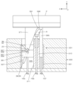
図4は、本発明の第2実施形態のスライド機構50の動きを説明するための図である。図5は、本発明の第2実施形態のスライド機構50の構成を示す分解図である。図1及び図2に示す第1実施形態のスライド機構1と同一の構成には同一の符号を付して説明を省略する。図4は、スライド機構50を正面から見た図であり、便宜上、図4(A)の左側を左、上側を上として説明する。
FIG. 4 is a diagram for explaining the movement of the slide mechanism 50 according to the second embodiment of the present invention. FIG. 5 is an exploded view showing the configuration of a slide mechanism 50 according to the second embodiment of the present invention. The same components as the slide mechanism 1 of the first embodiment shown in FIGS. 1 and 2 are given the same reference numerals, and the description thereof will be omitted. FIG. 4 is a front view of the slide mechanism 50, and for convenience, the left side of FIG. 4(A) will be referred to as the left and the upper side will be described as the top.
本発明の第2実施形態のスライド機構50も、第1実施形態のスライド機構1と同様に、スライダーが第1方向に続いて第2方向に移動可能に構成される。第1方向と第2方向は、予め規定された方向であり、第1方向と第2方向とは方向が異なる(図5参照)。以下、図4及び図5を用いて構成を具体的に説明する。
Slide mechanism 50 of the second embodiment of the present invention is configured such that the slider can move in a first direction and then in a second direction, similar to slide mechanism 1 of the first embodiment. The first direction and the second direction are predetermined directions, and the first direction and the second direction are different directions (see FIG. 5). The configuration will be specifically described below with reference to FIG. 4 and FIG. 5.
スライド機構50は、第1駒11と、第2駒61と、第1駒11及び第2駒61を案内する案内体81とからなる。本実施形態では、第2駒61がスライダー、案内体81がガイド本体、後述の案内溝88及び案内体81の上部内面87がガイド手段、第1案内部89が第1ガイド手段、第2案内部92の側面93及び案内体81の上部内面87が第2ガイド手段に該当する。また爪63及び第2駒61の側面73が係合手段、爪63の第1摺動面が第1係合手段、爪63の傾斜面68及び第2駒61の側面73が第2係合手段に該当する。
The slide mechanism 50 includes a first piece 11, a second piece 61, and a guide body 81 that guides the first piece 11 and the second piece 61. In this embodiment, the second piece 61 is a slider, the guide body 81 is a guide body, a guide groove 88 and an upper inner surface 87 of the guide body 81, which will be described later, are guide means, and the first guide part 89 is the first guide means and the second guide. The side surface 93 of the portion 92 and the upper inner surface 87 of the guide body 81 correspond to the second guide means. Further, the claw 63 and the side surface 73 of the second piece 61 are the engagement means, the first sliding surface of the claw 63 is the first engagement means, and the inclined surface 68 of the claw 63 and the side surface 73 of the second piece 61 are the second engagement means. It corresponds to means.
案内体81は、横断面がコ字状であり、矩形の底板82の両端部に側壁83、85を備える。左側壁83は、正面視において直線状であり、右側壁85は、上部が左側に突出している。右側壁85の中央から下部の内面86は、左側壁83の内面84と平行であり、右側壁85の上部内面87は、左上方に傾斜した傾斜面となっている。左側壁内面84及び右側壁内面86は、第1駒11のガイドとして機能する。底板82の内面には、案内溝88が設けられている。The guide body 81 has a U-shaped cross section and is provided with side walls 83, 85 at both ends of a rectangular bottom plate 82. The left side wall 83 is straight when viewed from the front, and the upper part of the right side wall 85 protrudes to the left. The inner surface 86 from the center to the lower part of the right side wall 85 is parallel to the inner surface 84 of the left side wall 83, and the upper inner surface 87 of the right side wall 85 is an inclined surface that slopes upward and to the left. The left side wall inner surface 84 and the right side wall inner surface 86 function as guides for the first piece 11. A guide groove 88 is provided on the inner surface of the bottom plate 82.
案内溝88は、凹溝であり、第2駒61を第1の方向(第1方向)に導く第1案内部89と、第2駒61を第2の方向(第2方向)に導く第2案内部92とを有する。本実施形態では、第1方向がY方向、第2方向が左斜め上である。第1案内部89と第2案内部92とは繋がっており、また第1案内部89の中心軸線M1と第2案内部92の中心軸線M2とは交差する(図5参照)。第1案内部89の左側面90と右側面91とは平行に設けられている。同様に第2案内部92の左側面93と右側面94とは平行に設けられている。
The guide groove 88 is a concave groove, and includes a first guide part 89 that guides the second piece 61 in a first direction (first direction) and a second guide part 89 that guides the second piece 61 in a second direction (second direction). 2 guide portions 92. In this embodiment, the first direction is the Y direction, and the second direction is diagonally upward to the left. The first guide part 89 and the second guide part 92 are connected, and the center axis M1 of the first guide part 89 and the center axis M2 of the second guide part 92 intersect (see FIG. 5). A left side surface 90 and a right side surface 91 of the first guide portion 89 are provided in parallel. Similarly, the left side surface 93 and right side surface 94 of the second guide portion 92 are provided in parallel.
第2案内部92の左側面93は、底板82の高さ方向(Y方向)のほぼ中央部で第1案内部89の左側面90に繋がり、第2案内部92の右側面94は、底板82の高さ方向の上部(Y方向)で第1案内部89の右側面91に繋がる。このため第2案内部92の右側面94は、第2案内部92の左側面93に比較して短い。また第2案内部92の右側面94は、右側壁85の上部内面87と面一となっている。
The left side surface 93 of the second guide portion 92 is connected to the left side surface 90 of the first guide portion 89 at approximately the center in the height direction (Y direction) of the bottom plate 82, and the right side surface 94 of the second guide portion 92 is connected to the right side surface 91 of the first guide portion 89 at the upper part in the height direction (Y direction) of the bottom plate 82. For this reason, the right side surface 94 of the second guide portion 92 is shorter than the left side surface 93 of the second guide portion 92. In addition, the right side surface 94 of the second guide portion 92 is flush with the upper inner surface 87 of the right wall 85.
第1駒11は、第1実施形態のスライド機構1の第1駒11と同一の構成ゆえ、説明を省略する。
The first piece 11 has the same configuration as the first piece 11 of the sliding mechanism 1 in the first embodiment, so its description is omitted.
第2駒61は、断面が矩形の棒状の部材であり、正面視において上部が左斜め上方向に屈曲している。第2駒61の中央から下部の両側面71、72は平行であり、第2駒61の上部両側面73、74は平行である。第2駒61の屈曲角度θ1(図4(B)参照)は、案内溝88の第1案内部89の中心軸線M1と第2案内部92の中心軸線M2との交角θ2(図5参照)と同じ角度である。
The second piece 61 is a rod-shaped member with a rectangular cross section, and its upper portion is bent diagonally upward to the left when viewed from the front. Both sides 71 and 72 of the second piece 61 from the center to the bottom are parallel, and both sides 73 and 74 of the upper part of the second piece 61 are parallel. The bending angle θ1 (see FIG. 4B) of the second piece 61 is the intersection angle θ2 between the center axis M1 of the first guide portion 89 of the guide groove 88 and the center axis M2 of the second guide portion 92 (see FIG. 5). is the same angle.
第2駒61は、本体下部の背面62に案内体81の案内溝88の第1案内部89に嵌り込む爪63を有する。爪63は、背面62から突出しており突起ということもできる。爪63の高さ(厚み)は、案内溝88の第1案内部89の深さと略同一である。爪63は、第2駒61の背面62を正面に見て五角形であり、右側面の下部が傾斜面68となっている。
The second piece 61 has a claw 63 on the back surface 62 at the bottom of the main body that fits into the first guide portion 89 of the guide groove 88 of the guide body 81. The claw 63 protrudes from the back surface 62 and can also be called a protrusion. The height (thickness) of the claw 63 is approximately the same as the depth of the first guide portion 89 of the guide groove 88. The claw 63 is pentagonal when the back surface 62 of the second piece 61 is viewed from the front, and the lower part of the right side surface forms an inclined surface 68.
爪63は、5つの側面64、65、66、67、68を備える。爪63の対向する側面64、65は、平行に設けられており、側面64は、第2駒61の下部の側面71と面一であり、側面65は、第2駒61の下部の側面72と面一である。爪63の側面64、65は、第1摺動面を構成する。第1摺動面は、案内体81に設けられた案内溝88の第1案内部89の両側面90、91に摺動自在に接触する面である。
The claw 63 includes five sides 64, 65, 66, 67, and 68. Opposing side surfaces 64 and 65 of the claw 63 are provided in parallel, the side surface 64 is flush with the lower side surface 71 of the second piece 61, and the side surface 65 is flush with the lower side surface 72 of the second piece 61. They are on the same page. Side surfaces 64 and 65 of the claw 63 constitute a first sliding surface. The first sliding surface is a surface that slidably contacts both side surfaces 90 and 91 of the first guide portion 89 of the guide groove 88 provided in the guide body 81 .
爪63の傾斜した側面68は、第2駒61の上部側面73、74と平行である。爪63の傾斜した側面68は、第2駒61の爪63を案内溝88の第2案内部92に嵌め込むと、第2案内部92の左側面93に接する。このとき第2駒61の上部側面73は、案内体81の上部右側面87に接する。爪63の傾斜した側面68及び第2駒61の上部側面73は、それぞれ第2案内部92の左側面93及び案内体81の上部右側面87に摺動自在に接触する第2摺動面を構成する。
The inclined side surface 68 of the claw 63 is parallel to the upper side surfaces 73 and 74 of the second piece 61. The inclined side surface 68 of the pawl 63 comes into contact with the left side surface 93 of the second guide section 92 when the pawl 63 of the second piece 61 is fitted into the second guide section 92 of the guide groove 88 . At this time, the upper side surface 73 of the second piece 61 contacts the upper right side surface 87 of the guide body 81. The inclined side surface 68 of the claw 63 and the upper side surface 73 of the second piece 61 have second sliding surfaces that slidably contact the left side surface 93 of the second guide part 92 and the upper right side surface 87 of the guide body 81, respectively. Configure.
スライド機構50の動きを、図4を用いて説明する。ここでは、第1駒11を入力端、第2駒61を出力端とする。第1案内部89に爪63を嵌め込み、第2駒61の底面に接するように第1駒11を案内体81に載せる。この状態で第1駒11の両側面12、13は、案内体81の両側壁内面84、86に摺動自在に接し、爪63の第1摺動面が第1案内部89の両側面90、91に摺動自在に接する(図4(A)参照)。
The movement of the slide mechanism 50 will be explained using FIG. 4. Here, the first piece 11 is used as an input end, and the second piece 61 is used as an output end. The claw 63 is fitted into the first guide part 89, and the first piece 11 is placed on the guide body 81 so as to be in contact with the bottom surface of the second piece 61. In this state, both side surfaces 12 and 13 of the first piece 11 are in slidable contact with the inner surfaces 84 and 86 of both side walls of the guide body 81, and the first sliding surface of the claw 63 is in contact with the both side surfaces 90 of the first guide portion 89. , 91 in a slidable manner (see FIG. 4(A)).
第1駒11を上方(Y方向)に押し上げると、第1駒11は、案内体81の両側壁内面84、86をガイドとし、両側面12、13を摺動させながら上昇する。第2駒61は、第1駒11に押し出され、案内体81の第1案内部89をガイドとし、爪63の第1摺動面を第1案内部89の両側面90、91に摺動させながら第1案内部89に沿って第1方向(Y方向)に移動する。When the first piece 11 is pushed upward (Y direction), the first piece 11 rises while sliding on both side surfaces 12, 13, using the inner sidewall surfaces 84, 86 of the guide body 81 as guides. The second piece 61 is pushed out by the first piece 11, and using the first guide portion 89 of the guide body 81 as a guide, moves in the first direction (Y direction) along the first guide portion 89 while sliding the first sliding surface of the claw 63 on both side surfaces 90, 91 of the first guide portion 89.
第2駒61は、第1駒11に押し出され上部の側面73が案内体81の右上部側面87に接触する位置まで移動すると、爪63の側面65は、これまで接触していた第1案内部89の側面90から外れる(図4(B)参照)。この状態から第1駒11を押し上げると、第2駒61は、第2案内部92及び案内体81の右上側面87をガイドとし、爪63の側面68を第2案内部92の左側面93に、第2駒61の側面73を案内体81の右上側面87にそれぞれ摺動させながら第2方向(左斜め上)に移動する(図4(C)参照)。
When the second piece 61 is pushed out by the first piece 11 and moves to a position where the upper side surface 73 contacts the upper right side surface 87 of the guide body 81, the side surface 65 of the pawl 63 is moved from the first guide It comes off from the side surface 90 of the portion 89 (see FIG. 4(B)). When the first piece 11 is pushed up from this state, the second piece 61 uses the second guide section 92 and the upper right side surface 87 of the guide body 81 as guides, and the side surface 68 of the claw 63 is pushed up onto the left side surface 93 of the second guide section 92. , the second piece 61 moves in the second direction (diagonally upward to the left) while sliding the side surface 73 of the second piece 61 on the upper right side surface 87 of the guide body 81 (see FIG. 4(C)).
第2実施形態のスライド機構50と第1実施形態のスライド機構1とを比較すると、第2駒を第2方向に案内する機構が異なる。第1実施形態のスライド機構1においては、第2駒21は、案内体31の案内溝38の第2案内部42に案内され第2方向に移動する。案内溝38の第2案内部42は、案内溝38の第1案内部39と同一平面上に設けられており、案内溝38の側面に摺動する第1摺動面及び第2摺動面は、爪23に設けられている。
Comparing the slide mechanism 50 of the second embodiment with the slide mechanism 1 of the first embodiment, the mechanism for guiding the second piece in the second direction is different. In the slide mechanism 1 of the first embodiment, the second piece 21 moves in the second direction while being guided by the second guide portion 42 of the guide groove 38 of the guide body 31. The second guide portion 42 of the guide groove 38 is provided on the same plane as the first guide portion 39 of the guide groove 38, and the first and second sliding surfaces that slide against the side surfaces of the guide groove 38 are provided on the claw 23.
一方、第2実施形態のスライド機構50においては、第2駒61は、案内体81の案内溝88の第2案内部92の左側面93と案内体81の右上側面87とに案内され第2方向に移動する。つまり第2実施形態のスライド機構50においては、案内溝88と案内体81の側面とが協働して第2駒61を第2方向に案内する。案内溝88の第2案内部92は、案内溝88の第1案内部89と同一平面上に設けられているが、案内体81の右上側面87は、案内溝88の第1案内部89と高さが異なる。また爪63の他に、第2駒61の側面73を摺動面としている点においても第1実施形態のスライド機構1と異なる。
On the other hand, in the slide mechanism 50 of the second embodiment, the second piece 61 is guided by the left side surface 93 of the second guide portion 92 of the guide groove 88 of the guide body 81 and the upper right side surface 87 of the guide body 81. move in the direction. That is, in the slide mechanism 50 of the second embodiment, the guide groove 88 and the side surface of the guide body 81 cooperate to guide the second piece 61 in the second direction. The second guide portion 92 of the guide groove 88 is provided on the same plane as the first guide portion 89 of the guide groove 88, but the upper right side surface 87 of the guide body 81 is provided on the same plane as the first guide portion 89 of the guide groove 88. Different heights. The slide mechanism 1 of the first embodiment is also different in that, in addition to the claw 63, the side surface 73 of the second piece 61 is used as a sliding surface.
以上のように第2実施形態のスライド機構50は、第1実施形態のスライド機構1と比較して、第2駒61を第2方向に案内する機構が異なるものの、基本的に案内溝により第2駒を異なる2つの方向に移動させることができる点において共通する。また爪61の作用効果も、スライド機構1の爪21と基本的に同じである。As described above, the sliding mechanism 50 of the second embodiment is different from the sliding mechanism 1 of the first embodiment in that the mechanism for guiding the second piece 61 in the second direction is different, but is basically the same in that the second piece can be moved in two different directions by the guide groove. The effect of the claw 61 is also basically the same as that of the claw 21 of the sliding mechanism 1.
スライド機構50において第1駒11の上面14と第2駒61の底面69とを蟻溝構造の連結機構としてもよい。具体的には、第1駒11の上面14又は第2駒61の底面69のいずれか一方に凸条(蟻溝凸条)を、他方に凸条に摺動自在に嵌り込む蟻溝を設ける。このような形態のスライド機構では、第1駒11が連結部材、第2駒61がスライダー、案内体81がガイド本体、案内体81の左右の側壁内面84、86が連結部材ガイド手段に相当する。In the slide mechanism 50, the top surface 14 of the first link 11 and the bottom surface 69 of the second link 61 may be connected as a dovetail structure. Specifically, a convex strip (dovetail convex strip) is provided on either the top surface 14 of the first link 11 or the bottom surface 69 of the second link 61, and a dovetail groove that slides freely into the convex strip is provided on the other. In this type of slide mechanism, the first link 11 corresponds to the connecting member, the second link 61 corresponds to the slider, the guide body 81 corresponds to the guide body, and the left and right side wall inner surfaces 84, 86 of the guide body 81 correspond to the connecting member guide means.
図6及び図7は、本発明の第3実施形態のアンダーカット処理機構101を備える成形用金型100の型閉じ時の断面図及び型開き後の断面図である。図8及び図9は、本発明の第3実施形態のアンダーカット処理機構101を備える成形用金型100の成形品Pの突き出し動作途中の断面図である。図10は、本発明の第3実施形態のアンダーカット処理機構101の構成を示す分解図である。図1及び図2に示す第1実施形態のスライド機構1と同一の構成には同一の符号を付して説明を省略する。
6 and 7 are a sectional view of a molding die 100 equipped with an undercut processing mechanism 101 according to a third embodiment of the present invention when the mold is closed, and a sectional view after the mold is opened. 8 and 9 are cross-sectional views of a molding die 100 equipped with an undercut processing mechanism 101 according to a third embodiment of the present invention during an ejection operation of a molded product P. FIG. 10 is an exploded view showing the configuration of an undercut processing mechanism 101 according to the third embodiment of the present invention. The same components as the slide mechanism 1 of the first embodiment shown in FIGS. 1 and 2 are given the same reference numerals, and the description thereof will be omitted.
本発明の第3実施形態の成形用金型100は、公知の射出成形用金型と同様、成形品Pの外面側を成形する固定型600と、成形品Pの内面側を成形する可動型700と、さらにアンダーカット処理機構101とを備える。便宜上、図6の固定型600側を上、可動型700側を下として説明する。また以下の説明において特に説明がない限り、左側とは図6における左側をいい、右側とはその反対側をいう。The molding die 100 of the third embodiment of the present invention, like known injection molding dies, comprises a fixed die 600 for molding the outer surface side of the molded product P, a movable die 700 for molding the inner surface side of the molded product P, and an undercut processing mechanism 101. For convenience, the fixed die 600 side in Figure 6 will be described as the top, and the movable die 700 side as the bottom. In the following description, unless otherwise specified, the left side refers to the left side in Figure 6, and the right side refers to the opposite side.
固定型600は、成形品Pの外面側を成形するキャビティ606を有する。可動型700は、成形品Pの内面側を成形するコア712を有する可動側型板711、可動側取付板750、スペーサーブロック751、2枚のエジェクタ台板762、エジェクタピン763、リターンピン765、スプリング767、エジェクタロッド768を備え、エジェクタ台板762、エジェクタピン763及びエジェクタロッド768等でエジェクタ機構760が構成される。このエジェクタ機構760は、一段の突き出し機構である。The fixed mold 600 has a cavity 606 that molds the outer surface side of the molded product P. The movable mold 700 includes a movable side mold plate 711 having a core 712 that molds the inner surface side of the molded product P, a movable side mounting plate 750, a spacer block 751, two ejector base plates 762, an ejector pin 763, a return pin 765, a spring 767, and an ejector rod 768. The ejector base plate 762, the ejector pin 763, the ejector rod 768, etc. constitute an ejector mechanism 760. This ejector mechanism 760 is a one-stage ejection mechanism.
成形用金型100は、成形工程、冷却工程を経て型開きを行い、エジェクタ台板762が成形品Pの型抜き方向(図6の上方向,Y方向)である可動側型板711に近づくように移動することでエジェクタピン763によって成形品Pの突き出し動作を行う。なお上記構成及び動作は、公知の成形用金型と同様であるため説明を省略する。
The molding die 100 is opened after a molding process and a cooling process, and the ejector base plate 762 approaches the movable side template 711 in the direction of mold removal of the molded product P (upward direction, Y direction in FIG. 6). By moving in this manner, the ejector pin 763 causes the molded product P to be ejected. Note that the above configuration and operation are the same as those of a known molding die, so a description thereof will be omitted.
本実施形態においてアンダーカット部P1は、成形品Pの端部から成形品Pの内側に突出した突出部P1であり、成形品Pの型抜き方向(Y方向)に対して交差している。また本実施形態に示す成形品Pは、アンダーカット部P1を抜く方向(X方向)の先に成形品Pの内側に突出した突出部P2を有する。成形品P、突出部P1及び突出部P2の形状は特に限定されるものではなく、成形品Pの素材もプラスチック等の合成樹脂に限らず、鉄や銅、アルミニウム等の金属でも良い。In this embodiment, the undercut portion P1 is a protrusion P1 that protrudes from the end of the molded product P toward the inside of the molded product P and intersects with the mold-pulling direction (Y direction) of the molded product P. The molded product P shown in this embodiment also has a protrusion P2 that protrudes toward the inside of the molded product P at the end of the direction in which the undercut portion P1 is pulled out (X direction). The shapes of the molded product P, the protrusion P1, and the protrusion P2 are not particularly limited, and the material of the molded product P is not limited to synthetic resin such as plastic, but may be metal such as iron, copper, or aluminum.
アンダーカット処理機構101は、成形品Pの成形時にアンダーカット部P1を成形し、エジェクタ機構760と同期し、成形品Pの突き出し時にアンダーカット部P1から外れることで、成形品Pを成形用金型100から型抜き可能とするものである。本実施形態のアンダーカット処理機構101は、第1実施形態のスライド機構1を利用したものである。The undercut processing mechanism 101 forms an undercut portion P1 when molding the molded product P, and synchronizes with the ejector mechanism 760 to disengage from the undercut portion P1 when the molded product P is ejected, thereby enabling the molded product P to be demolded from the molding die 100. The undercut processing mechanism 101 of this embodiment utilizes the slide mechanism 1 of the first embodiment.
アンダーカット処理機構101は、可動側型板711に埋設、固定されるホルダー121と、成形品Pのアンダーカット部P1を成形する成形コア191を先端に備える摺動駒171と、摺動駒171を摺動可能に保持する保持駒161とを備える。The undercut processing mechanism 101 comprises a holder 121 embedded and fixed in the movable side mold plate 711, a sliding piece 171 having a molding core 191 at its tip which molds the undercut portion P1 of the molded product P, and a holding piece 161 which holds the sliding piece 171 in a slidable manner.
本実施形態のホルダー121、成形コア191を先端に備える摺動駒171、保持駒161はそれぞれ、第1実施形態のスライド機構1の案内体31、第2駒21、第1駒11に相当する。また本実施形態では、摺動駒171がスライダー、ホルダー121がガイド本体、後述の案内溝141がガイド手段、第1案内部145が第1ガイド手段、第2案内部148が第2ガイド手段に該当する。また爪180が係合手段、爪180の第1摺動面が第1係合手段、爪180の第2摺動面が第2係合手段に該当する。また保持駒161と摺動駒171とが蟻溝構造により摺動自在に連結されており、保持駒161は、連結部材に該当し、ホルダー121の左右の側壁内面127、130は、連結部材ガイド手段に該当する。
The holder 121, the sliding piece 171 having the molded core 191 at the tip, and the holding piece 161 of this embodiment correspond to the guide body 31, the second piece 21, and the first piece 11 of the slide mechanism 1 of the first embodiment, respectively. . Further, in this embodiment, the sliding piece 171 is a slider, the holder 121 is a guide body, the guide groove 141 (described later) is a guide means, the first guide part 145 is a first guide means, and the second guide part 148 is a second guide means. Applicable. Further, the claw 180 corresponds to an engaging means, the first sliding surface of the claw 180 corresponds to a first engaging means, and the second sliding surface of the claw 180 corresponds to a second engaging means. Further, the holding piece 161 and the sliding piece 171 are slidably connected by a dovetail structure, the holding piece 161 corresponds to a connecting member, and the inner surfaces 127 and 130 of the left and right side walls of the holder 121 are used as connecting member guides. It corresponds to means.
ホルダー121は、可動側型板711の底面713に臨むように設けられた凹部714に嵌め込まれ、固定板715を介して可動側型板711に埋設、固定される。ホルダー121は、摺動駒171及び保持駒161を収納し、摺動駒171及び保持駒161の移動方向を規制する。ここでホルダー121が摺動駒171及び保持駒161を収納するとは、摺動駒171及び保持駒161全体を収容する他、摺動駒171及び保持駒161を部分的に収容する場合を含む。The holder 121 is fitted into a recess 714 provided facing the bottom surface 713 of the movable side mold plate 711, and is embedded and fixed in the movable side mold plate 711 via a fixing plate 715. The holder 121 stores the sliding piece 171 and the holding piece 161, and regulates the movement direction of the sliding piece 171 and the holding piece 161. Here, storing the sliding piece 171 and the holding piece 161 by the holder 121 includes storing the sliding piece 171 and the holding piece 161 in their entirety, as well as partially storing the sliding piece 171 and the holding piece 161.
ホルダー121は、2つの同一形状の半割ホルダー部材125を組合せてなり、上端面及び下端面が開口した内部空間を備える箱形筒状に形成されている(図10参照)。ホルダー121は、複数に分割された部材で形成されていてもよく、可動側型板711に一体的に形成されていてもよい。ホルダー121は、左側壁126の内面127、右側壁129の内面130が保持駒161のガイドとして機能し、正面壁内面及び背面壁内面135に摺動駒171をガイドする案内溝141を有する。
The holder 121 is formed by combining two half-split holder members 125 of the same shape, and is formed into a box-shaped cylinder having an internal space with open upper and lower end surfaces (see FIG. 10). The holder 121 may be formed of a plurality of divided members, or may be formed integrally with the movable template 711. In the holder 121, an inner surface 127 of the left wall 126 and an inner surface 130 of the right wall 129 function as guides for the holding piece 161, and a guide groove 141 for guiding the sliding piece 171 is provided on the inner surface of the front wall and the inner surface of the rear wall 135.
案内溝141は、凹溝であり、摺動駒171を第1方向に導く第1案内部145と、摺動駒171を第2方向に導く第2案内部148とを有する。第1案内部145は、成形用金型100の型開き方向(Y方向)に対して傾斜して設けられ、第2案内部148は、成形用金型100の型開き方向(Y方向)と平行に設けられている。第1案内部145と第2案内部148とは繋がっており、第1案内部145の中心軸線M1と第2案内部148の中心軸線M2とは交差する(図10参照)。
The guide groove 141 is a concave groove, and includes a first guide part 145 that guides the sliding piece 171 in a first direction, and a second guide part 148 that guides the sliding piece 171 in a second direction. The first guide part 145 is provided to be inclined with respect to the mold opening direction (Y direction) of the molding die 100, and the second guide part 148 is provided to be inclined with respect to the mold opening direction (Y direction) of the molding die 100. are placed in parallel. The first guide part 145 and the second guide part 148 are connected, and the center axis M1 of the first guide part 145 and the center axis M2 of the second guide part 148 intersect (see FIG. 10).
第1案内部145は、エジェクタ機構760と同期して、摺動駒171に取付けられた成形コア191がアンダーカット部P1から外れるように摺動駒171を左斜め上(第1方向)に案内する。ここで成形コア191がアンダーカット部P1から外れる方向とは、アンダーカット部P1を変形及び損傷させることなく成形コア191がアンダーカット部P1から外れる方向である。
The first guide part 145 guides the sliding piece 171 diagonally upward to the left (first direction) in synchronization with the ejector mechanism 760 so that the molded core 191 attached to the sliding piece 171 comes off the undercut part P1. do. Here, the direction in which the molding core 191 comes off from the undercut portion P1 is the direction in which the molding core 191 comes off from the undercut portion P1 without deforming or damaging the undercut portion P1.
第1案内部145は、中心軸線M1が成形品Pのアンダーカット部P1の形状、特に、アンダーカット部P1のX方向への突出量と、突き出しピン745のストロークとに応じて、成形品Pの突き出し時に成形コア191が成形品Pのアンダーカット部P1から外れるように決められる。
The first guide portion 145 has a central axis M1 that is formed on the molded product P according to the shape of the undercut portion P1 of the molded product P, in particular, the amount of protrusion of the undercut portion P1 in the X direction, and the stroke of the ejector pin 745. The molding core 191 is set so as to come off the undercut portion P1 of the molded product P during ejection.
第2案内部148は、アンダーカット部P1から外れた成形コア191が、アンダーカット部P1の抜き方向(X方向)の先に位置する突出部P2に衝突しないように成形コア191を案内する。本実施形態において第2案内部148は、成形コア191を型開き方向(第2方向,Y方向)に案内するように設けられている。これにより成形コア191のX方向への移動を防ぎ突起部P2への衝突を回避する。The second guide portion 148 guides the molding core 191 so that the molding core 191, which has come out of the undercut portion P1, does not collide with the protruding portion P2 located beyond the undercut portion P1 in the removal direction (X direction). In this embodiment, the second guide portion 148 is provided to guide the molding core 191 in the mold opening direction (second direction, Y direction). This prevents the molding core 191 from moving in the X direction and avoids collision with the protruding portion P2.
本実施形態において第2案内部148の中心軸線(案内方向)M2は、成形用金型100の型開き方向(Y方向)に平行に設けられているがこれに限定されるものではない。アンダーカット部P1から外れた成形コア191を突出部P2に衝突させず、またアンダーカット部P1から外れた状態を維持できれば第2案内部148の中心軸線M2は、成形用金型100の型開き方向(Y方向)と同一でなくてもよい。In this embodiment, the central axis (guidance direction) M2 of the second guide portion 148 is provided parallel to the mold opening direction (Y direction) of the molding die 100, but is not limited to this. The central axis M2 of the second guide portion 148 does not need to be the same as the mold opening direction (Y direction) of the molding die 100 as long as the molding core 191 that has come out of the undercut portion P1 does not collide with the protrusion P2 and can be kept out of the undercut portion P1.
保持駒161は、直方体形状を有し、底面にエジェクタ台板762に固定された突き出しピン745が連結し、ホルダー121内に収容される。保持駒161は、左側面165及び右側面166をホルダー121の左側壁内面127、右側壁内面130に摺動可能に接し、突き出しピン745に突き出され左側壁内面127及び右側壁内面130に案内され型抜き方向(Y方向)に移動する。The retaining piece 161 has a rectangular parallelepiped shape, and an ejector pin 745 fixed to the ejector base plate 762 is connected to the bottom surface of the retaining piece 161, and the retaining piece 161 is housed in the holder 121. The left side surface 165 and the right side surface 166 of the retaining piece 161 are in slidable contact with the left side wall inner surface 127 and the right side wall inner surface 130 of the holder 121, and the retaining piece 161 is ejected by the ejector pin 745 and guided by the left side wall inner surface 127 and the right side wall inner surface 130 to move in the demolding direction (Y direction).
保持駒161は、上面にX方向に延びる凸条(蟻溝凸条)168を備える。凸条168は、アンダーカット部P1を抜く方向と平行に設けられ、摺動駒171の本体175の下端に設けられた蟻溝176が摺動自在に係合し、成形コア191がアンダーカット部P1から外れるように摺動駒171を案内する。
The holding piece 161 includes a convex line (dovetail convex line) 168 extending in the X direction on the upper surface. The protrusion 168 is provided parallel to the direction in which the undercut portion P1 is pulled out, and the dovetail groove 176 provided at the lower end of the main body 175 of the sliding piece 171 is slidably engaged, and the molded core 191 is inserted into the undercut portion. Guide the sliding piece 171 so that it comes off from P1.
摺動駒171は、断面が矩形の直線状の本体175を有し、本体175の先端部には成形コア191が取付けられ、下端には保持駒161の凸条168に摺動可能に係合する蟻溝176が設けられている。保持駒161の凸条(蟻溝凸条)168と摺動駒171の蟻溝176とで摺動自在に連結する蟻溝構造を形成する。また摺動駒171は、正面側の一部、背面側の一部にホルダー121の案内溝141に嵌り込む爪180を有する。爪180は、第1実施形態のスライド機構1の第2駒21に設けられた爪23に相当する。爪180は、断面形状が矩形であり、本体175の中央から下端にかけて正面側及び背面側に突出するように設けられ凸条ということもできる。
The sliding piece 171 has a linear main body 175 with a rectangular cross section, a molded core 191 is attached to the tip of the main body 175, and the lower end is slidably engaged with the protrusion 168 of the holding piece 161. A dovetail groove 176 is provided. A dovetail groove structure is formed in which the protrusions 168 of the holding piece 161 and the dovetail grooves 176 of the sliding piece 171 are slidably connected. Further, the sliding piece 171 has a claw 180 that fits into the guide groove 141 of the holder 121 on a part of the front side and a part of the back side. The pawl 180 corresponds to the pawl 23 provided on the second piece 21 of the slide mechanism 1 of the first embodiment. The claw 180 has a rectangular cross-sectional shape and is provided so as to protrude from the center to the lower end of the main body 175 toward the front side and the back side, and can also be called a protruding strip.
爪180の左側面181及び右側面182は、成形コア191がアンダーカット部P1から外れるまでの間、それぞれがホルダー121に設けられた案内溝141の第1案内部145の左側面146、右側面147に接する。また爪180の上側面183、下側面184は、アンダーカット部P1から外れた成形コア191を型抜き方向(Y方向)に案内すべく、ホルダー121に設けられた案内溝141の第2案内部148の左側面149、右側面150に接する。爪180の対向する左側面181及び右側面182が第1摺動面を、爪180の対向する上側面183及び下側面184が第2摺動面を構成する。The left side surface 181 and the right side surface 182 of the claw 180 contact the left side surface 146 and the right side surface 147 of the first guide portion 145 of the guide groove 141 provided in the holder 121, respectively, until the molding core 191 is released from the undercut portion P1. The upper side surface 183 and the lower side surface 184 of the claw 180 contact the left side surface 149 and the right side surface 150 of the second guide portion 148 of the guide groove 141 provided in the holder 121 to guide the molding core 191 released from the undercut portion P1 in the demolding direction (Y direction). The opposing left side surface 181 and the right side surface 182 of the claw 180 constitute the first sliding surface, and the opposing upper side surface 183 and the lower side surface 184 of the claw 180 constitute the second sliding surface.
成形コア191は、アンダーカット部P1を含む成形品Pの一部に沿った形状のブロック部材であり、摺動駒171の上端面にネジ止め等で固定されている。成形コア191の形状は、成形品Pの形状に応じて決められる。なお成形コア191は、摺動駒171に一体的に形成されていてもよい。The molding core 191 is a block member shaped to fit a portion of the molded product P including the undercut portion P1, and is fixed to the upper end surface of the sliding piece 171 by means of screws or the like. The shape of the molding core 191 is determined according to the shape of the molded product P. The molding core 191 may be formed integrally with the sliding piece 171.
次に、成形用金型100において成形品Pを射出成形によって成形する場合を例として、本実施形態の成形用金型100の動作、作用を説明する。成形品Pの成形時には、摺動駒171がホルダー121内に収容され、成形コア191が成形品Pのアンダーカット部P1を成形するように位置する(図6参照)。成形用金型100は、固定型600と可動型700とのパーティング面(PL面)が合わされキャビティ部が形成され、溶融材料が射出され成形品Pの成形が行われる。
Next, the operation and effect of the molding die 100 of the present embodiment will be described, taking as an example a case where the molded product P is molded by injection molding in the molding die 100. When molding the molded product P, the sliding piece 171 is housed in the holder 121, and the molding core 191 is positioned so as to mold the undercut portion P1 of the molded product P (see FIG. 6). In the molding die 100, the parting surfaces (PL surfaces) of the fixed die 600 and the movable die 700 are brought together to form a cavity, and a molten material is injected to form the molded product P.
溶融材料の射出、冷却の各工程が終了すると、型開き、成形品Pの取り出し工程に移行する。型開き、取り出し工程における成形用金型100の動作は次の通りである。
When the steps of injection and cooling of the molten material are completed, the process moves to the step of opening the mold and taking out the molded product P. The operation of the molding die 100 during the mold opening and ejecting steps is as follows.
型開き後(図7参照)、図示を省略した突き出し装置を介してエジェクタロッド768が押し出され、エジェクタ台板762が上方(Y方向)に移動する。これに伴いエジェクタ台板762上に立設したエジェクタピン763が成形品PをY方向に突き出す(図8参照)。
After opening the mold (see FIG. 7), the ejector rod 768 is pushed out via an ejecting device (not shown), and the ejector base plate 762 moves upward (in the Y direction). Accordingly, the ejector pin 763 erected on the ejector base plate 762 projects the molded product P in the Y direction (see FIG. 8).
同時にホルダー121に収容された保持駒161が突き出しピン745に突き出されエジェクタピン763と同量Y方向へ移動する。保持駒161のY方向への移動に伴って、摺動駒171は、爪180の第1摺動面をホルダー121に設けられた案内溝141の第1案内部145の左側面146、右側面147に摺動させながら、図6に示す成形位置からホルダー121の第1案内部145に沿って移動する。これにより成形コア191は、Y方向及びX方向へ同時に移動しアンダーカット部P1から遠ざかる。At the same time, the retaining piece 161 housed in the holder 121 is pushed out by the ejection pin 745 and moves in the Y direction the same amount as the ejector pin 763. As the retaining piece 161 moves in the Y direction, the sliding piece 171 moves from the molding position shown in Figure 6 along the first guide portion 145 of the holder 121 while sliding the first sliding surface of the claw 180 against the left side surface 146 and right side surface 147 of the first guide portion 145 of the guide groove 141 provided in the holder 121. As a result, the molding core 191 moves simultaneously in the Y direction and the X direction, moving away from the undercut portion P1.
エジェクタ台板762が型締め状態からΔH1だけ上昇すると、摺動駒171の爪180の上側面183がホルダー121に設けられた案内溝141の第2案内部148の左側面149に接する。この時点で摺動駒171に取付けられた成形コア191は、アンダーカット部P1から完全に外れる(図8参照)。このとき摺動駒171は、爪180の上側面183がホルダー121の第2案内部148の左側面149に接し、かつ爪180の右側面182が、ホルダー121に設けられた案内溝141の第1案内部145の右側面147から外れている。When the ejector base plate 762 rises by ΔH1 from the mold clamping state, the upper surface 183 of the claw 180 of the sliding top 171 comes into contact with the left side surface 149 of the second guide portion 148 of the guide groove 141 provided in the holder 121. At this point, the molding core 191 attached to the sliding top 171 is completely removed from the undercut portion P1 (see FIG. 8). At this time, the upper surface 183 of the claw 180 of the sliding top 171 comes into contact with the left side surface 149 of the second guide portion 148 of the holder 121, and the right side surface 182 of the claw 180 comes out of the right side surface 147 of the first guide portion 145 of the guide groove 141 provided in the holder 121.
エジェクタ台板762が型締め状態からΔH1だけ上昇した時点で、成形品Pは取り出し可能な位置まで達していない(図8参照)。このためエジェクタ台板762は、引き続き上昇し、エジェクタピン763は、成形品Pの内側に接した状態で引き続き成形品Pを突き出す。保持駒161も同じように上昇し、摺動駒171は、爪180の第2摺動面をホルダー121に設けられた案内溝141の第2案内部148の左右側面149、150に摺動させながら上昇する。When the ejector base plate 762 has risen by ΔH1 from the mold clamping state, the molded product P has not yet reached a position where it can be removed (see FIG. 8). Therefore, the ejector base plate 762 continues to rise, and the ejector pin 763 continues to eject the molded product P while in contact with the inside of the molded product P. The holding piece 161 also rises in the same manner, and the sliding piece 171 rises while sliding the second sliding surface of the claw 180 against the left and right side surfaces 149, 150 of the second guide portion 148 of the guide groove 141 provided in the holder 121.
ホルダー121の案内溝141の第2案内部148は、中心軸線M2がY方向に平行であるため成形コア191は、+X方向、-X方向に移動することなく上昇する。成形品Pには、アンダーカット部P1の抜き方向(+X方向)の先に突出部P2を有するが、成形コア191は、+X方向には移動しないので成形コア191が突出部P2に衝突することはない。さらに成形コア191は、-X方向にも移動しないので成形品Pを取り出す際にアンダーカット部P1が成形コア191に引っ掛かることもない(図9参照)。これにより成形品Pを損傷させることなく取り出すことができる。
The second guide portion 148 of the guide groove 141 of the holder 121 has a central axis M2 parallel to the Y direction, so the molding core 191 rises without moving in the +X or -X direction. The molded product P has a protrusion P2 at the end of the undercut portion P1 in the removal direction (+X direction), but since the molding core 191 does not move in the +X direction, it does not collide with the protrusion P2. Furthermore, since the molding core 191 does not move in the -X direction, the undercut portion P1 does not get caught on the molding core 191 when the molded product P is removed (see Figure 9). This allows the molded product P to be removed without being damaged.
成形品Pの取り出し後、次の成形品Pを成形すべく、再度、成形用金型100の型締めが行われる。型締め時には、可動型700全体が図9の上方向に移動するとともに、エジェクタ台板762が図9の下方向に移動する。アンダーカット処理機構101は、可動型700の移動に連動して、保持駒161が先とは逆向きに移動し、成形コア191の上面がコア712の上面と面一になる。型締めが完了すると、成形材料が射出され、次の成形品Pが成形される。成形用金型100の型開き状態から型締めへの動きは、従来のアンダーカット処理機構を備える成形用金型と基本的に同じである。
After taking out the molded product P, the molding die 100 is again clamped in order to mold the next molded product P. During mold clamping, the entire movable mold 700 moves upward in FIG. 9, and the ejector base plate 762 moves downward in FIG. In the undercut processing mechanism 101, the holding piece 161 moves in the opposite direction in conjunction with the movement of the movable mold 700, so that the upper surface of the molding core 191 becomes flush with the upper surface of the core 712. When the mold clamping is completed, the molding material is injected and the next molded product P is molded. The movement of the molding die 100 from the open state to the clamping state is basically the same as that of a conventional molding die equipped with an undercut processing mechanism.
以上のように成形用金型100、アンダーカット処理機構101は、コンパクトでかつ簡素な構成ながら成形用金型100の成形品Pの取り出し操作に連動して保持駒161がホルダー121内を摺動しながら上昇し、摺動駒171がホルダー121にガイドされ成形コア191がアンダーカット部P1から外れるように移動するので容易にまた確実にアンダーカット部P1を抜くことができる。As described above, the molding die 100 and undercut processing mechanism 101 are compact and simply configured, but in conjunction with the operation of removing the molded product P from the molding die 100, the holding piece 161 slides upward within the holder 121, and the sliding piece 171 is guided by the holder 121 and moves so that the molding core 191 disengages from the undercut portion P1, making it possible to easily and reliably remove the undercut portion P1.
さらに成形用金型100、アンダーカット処理機構101は、アンダーカット部P1を抜くように成形コア191を移動させた後に、さらに成形品Pの取り出し操作と連動し、成形コア191を型抜き方向(Y方向)に移動させるのでアンダーカット部P1を抜いた先に突出部P2を有するような成形品Pであっても容易にまた確実に型抜きすることができる。
Furthermore, after moving the molding core 191 so as to remove the undercut portion P1, the molding die 100 and the undercut processing mechanism 101 further move the molding core 191 in the mold removal direction ( Since the molded product P is moved in the Y direction), even if the molded product P has a protruding portion P2 at the end of the undercut portion P1, it can be easily and reliably removed from the mold.
またアンダーカット処理機構101は、摺動駒171及び保持駒161をホルダー121内に収納した状態で成形用金型100に組込むことができるので、コンパクトに構成可能であるとともに、成形用金型100への取付けが容易である。特にホルダー121、保持駒161、摺動駒171及び成形コア191を1つの独立したユニットとすることが可能であり、アンダーカット処理機構101をユニットとすれば、成形用金型100への取付けがより容易となる。In addition, the undercut processing mechanism 101 can be incorporated into the molding die 100 with the sliding piece 171 and the holding piece 161 stored in the holder 121, so it can be configured compactly and is easy to attach to the molding die 100. In particular, the holder 121, holding piece 161, sliding piece 171, and molding core 191 can be made into a single independent unit, and if the undercut processing mechanism 101 is made into a unit, it becomes easier to attach it to the molding die 100.
図11及び図12は、本発明の第4実施形態のゲート切断機構201を備える成形用金型200の型閉じ時の断面図及び型開き途中の断面図である。図13、図14及び図15は、本発明の第4実施形態のゲート切断機構201を備える成形用金型200の型開き途中の断面図、型開き後の断面図及び成形品Pの突き出し途中の断面図である。図16は、本発明の第4実施形態のゲート切断機構201の構成を示す分解図である。図6~図10に示す本発明の第3実施形態の成形用金型100及びアンダーカット処理機構101と同一の構成には同一の符号を付して説明を省略する。
FIGS. 11 and 12 are a sectional view of a molding die 200 equipped with a gate cutting mechanism 201 according to a fourth embodiment of the present invention when the mold is closed, and a sectional view of the mold during opening. FIGS. 13, 14, and 15 are a cross-sectional view of a molding die 200 equipped with a gate cutting mechanism 201 according to a fourth embodiment of the present invention during mold opening, a cross-sectional view after mold opening, and a cross-sectional view during ejection of a molded product P. FIG. FIG. 16 is an exploded view showing the configuration of a gate cutting mechanism 201 according to a fourth embodiment of the present invention. The same components as the molding die 100 and the undercut processing mechanism 101 of the third embodiment of the present invention shown in FIGS. 6 to 10 are given the same reference numerals, and the description thereof will be omitted.
成形用金型200は、成形用金型100と同様に、成形品Pの外面側を成形する固定型602と、成形品Pの内面側を成形する可動型702と、さらにゲートGを切断するゲート切断機構201を備える。便宜上、図11の固定型602側を上、可動型702側を下として説明する。また以下の説明において特に説明がない限り、左側とは図11における左側をいい、右側とはその反対側をいう。Similar to molding die 100, molding die 200 includes a fixed die 602 that molds the outer surface of molded product P, a movable die 702 that molds the inner surface of molded product P, and a gate cutting mechanism 201 that cuts gate G. For convenience, the fixed die 602 side in Fig. 11 will be described as the top, and the movable die 702 side as the bottom. In the following description, unless otherwise specified, the left side refers to the left side in Fig. 11, and the right side refers to the opposite side.
固定型602は、第3実施形態の固定型600と同様に、成形品Pの外面を形成するキャビティ606を備える固定側型板605を有する。固定側型板605は、キャビティ606に隣接してゲート切断機構201を収容する収容部608を有する。収容部608は、固定側型板605を上下方向に貫通するように設けられている。また固定側型板605は、底面610に後述の可動駒205を進退させるスプリング218が嵌る凹部612を有する。
The fixed die 602 has a fixed side template 605 that includes a cavity 606 that forms the outer surface of the molded product P, similar to the fixed die 600 of the third embodiment. The stationary template 605 has a housing section 608 adjacent to the cavity 606 that houses the gate cutting mechanism 201 . The accommodating portion 608 is provided to vertically penetrate the fixed side template 605. Furthermore, the fixed side template 605 has a recess 612 on the bottom surface 610 into which a spring 218 for advancing and retracting the movable piece 205, which will be described later, is fitted.
可動型702は、可動型700と同様に成形品Pの内面を形成するコア712を備える可動側型板711を有する。可動側型板711は、可動駒205が嵌り込む収容部720を有する。可動駒205が、収容部720に嵌り込むことでランナーRが形成される。また可動側型板711には、成形品Pを押出す(突き出す)エジェクタピン763が挿通する挿通孔の他に、ゲートG切断後のランナーRに残された材料を押出す(突き出す)エジェクタピン746が挿通する挿通孔が設けられている。
Like the movable mold 700, the movable mold 702 has a movable mold plate 711 that includes a core 712 that forms the inner surface of the molded product P. The movable template 711 has a housing portion 720 into which the movable piece 205 is fitted. A runner R is formed by fitting the movable piece 205 into the housing portion 720. In addition, the movable template 711 includes an insertion hole through which an ejector pin 763 for extruding (projecting) the molded product P is inserted, as well as an ejector pin for extruding (projecting) the material left on the runner R after cutting the gate G. An insertion hole through which 746 is inserted is provided.
可動駒205は、直方体形状を有し、ホルダー221の下部が嵌り込む上面に臨む凹部208を有する。また可動駒205は、連結ピン215を取付けるための底部から上部へ向かう凹部210、さらに可動駒205の上面から凹部210につながる貫通孔を有する。貫通孔の直径は、凹部210の直径よりも小さく設定されている。
The movable piece 205 has a rectangular parallelepiped shape and has a recess 208 facing the upper surface into which the lower part of the holder 221 is fitted. The movable piece 205 also has a recess 210 extending from the bottom to the top for attaching a connecting pin 215, and a through hole that connects to the recess 210 from the top surface of the movable piece 205. The diameter of the through hole is set smaller than the diameter of the recess 210.
可動駒205は、連結ピン215を介して固定側型板605に連結されている。連結ピン215は、凹部210につながる貫通孔よりも直径の小さいピン本体の先端部に凹部210の直径より小さい鍔216を有する。連結ピン215は、鍔216が凹部210内に位置するように凹部210につながる貫通孔に挿通され、基端部が凹部612の底に固定されている。可動駒205を押し出すスプリング218は、連結ピン215に挿通され、下端を可動駒205の上面206に接し、凹部612に収容されるように取付けられる。
The movable piece 205 is connected to the stationary template 605 via a connecting pin 215. The connecting pin 215 has a flange 216 smaller in diameter than the recess 210 at the tip of the pin main body, which has a smaller diameter than the through hole connected to the recess 210 . The connecting pin 215 is inserted into the through hole connected to the recess 210 so that the collar 216 is located within the recess 210, and the base end is fixed to the bottom of the recess 612. A spring 218 that pushes out the movable piece 205 is inserted through the connecting pin 215, has a lower end in contact with the upper surface 206 of the movable piece 205, and is attached so as to be accommodated in the recess 612.
収容部720は、正面視において略矩形の凹部であり(図15参照)、収容部720の底面722の左側には、ランナーRを形成する凹部724が設けられている(図15参照)。さら収容部720の左上端と接するコア712には、カッター291の先端部293を保護する緩衝材212が取付けられている(図15参照)。緩衝材212は、軟鉄などカッター291の先端部293に比較して柔らかい材料からなる。
The accommodating portion 720 is a substantially rectangular recess when viewed from the front (see FIG. 15), and a recess 724 forming a runner R is provided on the left side of the bottom surface 722 of the accommodating portion 720 (see FIG. 15). Furthermore, a cushioning material 212 that protects the tip 293 of the cutter 291 is attached to the core 712 in contact with the upper left end of the housing section 720 (see FIG. 15). The cushioning material 212 is made of a material that is softer than the tip 293 of the cutter 291, such as soft iron.
ゲート切断機構201は、成形品PとランナーRとをつなぐゲートGを切断する装置であり、成形用金型200の型開きに連動してカッター291でゲートGを切断し、ゲートGを切断したカッター291をゲートGから遠ざけることでランナーRに残った材料を取出し可能とする。本実施形態のゲート切断機構201は、第1実施形態のスライド機構1を利用したものである。
The gate cutting mechanism 201 is a device that cuts the gate G that connects the molded product P and the runner R, and cuts the gate G with a cutter 291 in conjunction with the opening of the molding die 200. By moving the cutter 291 away from the gate G, the material remaining on the runner R can be taken out. The gate cutting mechanism 201 of this embodiment utilizes the slide mechanism 1 of the first embodiment.
ゲート切断機構201は、ゲートGを切断するカッター291と、カッター291と連結しカッター291をスライドさせる摺動駒271と、摺動駒271を摺動可能に保持する保持駒261と、保持駒261を進退可能に収容するホルダー221とを備える。The gate cutting mechanism 201 includes a cutter 291 for cutting the gate G, a sliding piece 271 for connecting with the cutter 291 and sliding the cutter 291, a holding piece 261 for holding the sliding piece 271 in a slidable manner, and a holder 221 for housing the holding piece 261 so that it can move forward and backward.
本実施形態の摺動駒271、保持駒261、ホルダー221は、それぞれ第1実施形態のスライド機構1の第2駒21、第1駒11、案内体31に相当する。また本実施形態では、摺動駒271がスライダー、ホルダー221がガイド本体、後述の案内溝241がガイド手段、第1案内部245が第1ガイド手段、第2案内部248が第2ガイド手段に該当する。また爪280が係合手段、爪280の第1摺動面が第1係合手段、爪280の第2摺動面が第2係合手段に該当する。また保持駒261と摺動駒271とが蟻溝構造により摺動自在に連結されており、保持駒261は、連結部材に該当し、ホルダー221の左右の側壁内面227、230は、連結部材ガイド手段に該当する。The sliding piece 271, the holding piece 261, and the holder 221 of this embodiment correspond to the second piece 21, the first piece 11, and the guide body 31 of the slide mechanism 1 of the first embodiment, respectively. In this embodiment, the sliding piece 271 corresponds to the slider, the holder 221 corresponds to the guide body, the guide groove 241 described below corresponds to the guide means, the first guide portion 245 corresponds to the first guide means, and the second guide portion 248 corresponds to the second guide means. The claw 280 corresponds to the engagement means, the first sliding surface of the claw 280 corresponds to the first engagement means, and the second sliding surface of the claw 280 corresponds to the second engagement means. The holding piece 261 and the sliding piece 271 are connected to each other by a dovetail structure so that they can slide freely, the holding piece 261 corresponds to the connecting member, and the left and right sidewall inner surfaces 227, 230 of the holder 221 correspond to the connecting member guide means.
ホルダー221は、保持駒261を進退可能に収容し、保持駒261を上下方向に案内する。さらにホルダー221は、摺動駒271に取付けられたカッター291がゲートGを切断するように案内すると共に、ゲートGを切断したカッター291をゲートGから遠ざけるように案内する。ホルダー221は、2つの同一形状の半割ホルダー部材225を組合せてなり、上面及び下面が開口した内部空間を備える箱形筒状に形成されている。ホルダー221は、複数の部材に分割して形成されていてもよく、固定側型板605に一体的に形成されていてもよい。
The holder 221 accommodates the holding piece 261 in a movable manner and guides the holding piece 261 in the vertical direction. Furthermore, the holder 221 guides the cutter 291 attached to the sliding piece 271 to cut the gate G, and also guides the cutter 291 that has cut the gate G away from the gate G. The holder 221 is formed by combining two half-split holder members 225 of the same shape, and is formed into a box-shaped cylinder having an internal space with an open top and bottom. The holder 221 may be formed by being divided into a plurality of members, or may be formed integrally with the stationary template 605.
ホルダー221は、摺動駒271を第1方向及び第1方向に続き第2方向に案内する点において第3実施形態のホルダー121と共通する。一方で、ホルダー221は、カッター291を備える摺動駒271を摺動自在に収容するため、第3実施形態のホルダー121と形態が異なる。The holder 221 is similar to the holder 121 of the third embodiment in that it guides the sliding piece 271 in a first direction and then in a second direction following the first direction. However, the holder 221 has a different shape from the holder 121 of the third embodiment because it accommodates the sliding piece 271 equipped with the cutter 291 in a freely slidable manner.
ホルダー221は、左側壁226が背面壁234に比較して短く左側面の下方は開口している。この開口部は、カッター291の出入口となる。また左側壁226の下部には内側に突出した段差部228が設けられている。また右側壁229の下部にも内側に突出した段差部231が設けられている。左側壁内面227、右側壁内面230は、保持駒261のガイドとして機能し、左右の段差部228、231は、保持駒261のストッパーとして機能する。ホルダー221の正面壁内面及び背面壁内面235には、第3実施形態のホルダー121と同様に摺動駒271をガイドする案内溝241を有する。The left side wall 226 of the holder 221 is shorter than the rear wall 234, and is open at the bottom of the left side. This opening serves as an entrance and exit for the cutter 291. A step 228 protruding inward is provided at the bottom of the left side wall 226. A step 231 protruding inward is also provided at the bottom of the right side wall 229. The left side wall inner surface 227 and the right side wall inner surface 230 function as guides for the retaining piece 261, and the left and right step portions 228, 231 function as stoppers for the retaining piece 261. The front wall inner surface and rear wall inner surface 235 of the holder 221 have guide grooves 241 that guide the sliding piece 271, similar to the holder 121 of the third embodiment.
案内溝241は、凹溝であり、背面壁内面235を正面に見て、くの字状である(図16参照)。案内溝241は、摺動駒271を第1方向に導く第1案内部245と、摺動駒271を第2方向に導く第2案内部248とを有する。第1案内部245は、上部が下部に比較して右側に位置し右斜め上方向に傾斜して設けられ、第2案内部248は、上部が下部に比較して左側に位置し左斜め上方向に傾斜する。第1案内部245と第2案内部248とは繋がっており、第1案内部245の中心軸線M1と第2案内部248の中心軸線M2とは交差する(図16参照)。
The guide groove 241 is a concave groove, and has a dogleg shape when looking at the rear wall inner surface 235 from the front (see FIG. 16). The guide groove 241 has a first guide part 245 that guides the sliding piece 271 in a first direction, and a second guide part 248 that guides the sliding piece 271 in a second direction. The first guide part 245 has an upper part located on the right side compared to the lower part and is inclined diagonally upward to the right, and the second guide part 248 has an upper part located on the left side compared to the lower part and is provided diagonally upward to the left. tilt in the direction. The first guide part 245 and the second guide part 248 are connected, and the center axis M1 of the first guide part 245 and the center axis M2 of the second guide part 248 intersect (see FIG. 16).
第1案内部245は、エジェクタ機構760と同期して、摺動駒271に連結するカッター291がゲートGを切断するように摺動駒271を案内する。一方、第2案内部248は、エジェクタ機構760と同期して、ゲートGを切断したカッター291がゲートGから遠ざかるように摺動駒271を案内する。
The first guide portion 245 guides the sliding piece 271 so that the cutter 291 connected to the sliding piece 271 cuts the gate G in synchronization with the ejector mechanism 760. On the other hand, the second guide portion 248 guides the sliding piece 271 so that the cutter 291 that cut the gate G moves away from the gate G in synchronization with the ejector mechanism 760.
ホルダー221は、左側壁226の下端が、固定側型板605の底面610と面一となるように収容部608に取付けられている。このためカッター291の出入口を含むホルダー221の下部は、固定側型板605の底面610から下方に突出している。ホルダー221のうち固定側型板605の底面610から下方に突出している部分は、型閉じ時には可動駒205の凹部208に収容可能に構成されている。
The holder 221 is attached to the housing part 608 so that the lower end of the left side wall 226 is flush with the bottom surface 610 of the stationary template 605. Therefore, the lower part of the holder 221 including the entrance and exit of the cutter 291 protrudes downward from the bottom surface 610 of the stationary template 605. A portion of the holder 221 that protrudes downward from the bottom surface 610 of the stationary mold plate 605 is configured to be accommodated in the recess 208 of the movable piece 205 when the mold is closed.
保持駒261は、直方体形状を有し、底面にX方向に延びる凸条(蟻溝凸条)268を備える。凸条268には、摺動駒271の本体275の上端に設けられた蟻溝276が摺動自在に係合し、摺動駒271に取付けられたカッター291を+X方向、-X方向に案内する。また保持駒261は、上面262に臨む凹部263を有する。凹部263は、保持駒261を下方に突き出すスプリング270の収容部であり、2個設けられている。
The holding piece 261 has a rectangular parallelepiped shape and includes a protrusion (dovetail protrusion) 268 extending in the X direction on the bottom surface. A dovetail groove 276 provided at the upper end of the main body 275 of the sliding piece 271 is slidably engaged with the protrusion 268, and guides the cutter 291 attached to the sliding piece 271 in the +X direction and the -X direction. do. The holding piece 261 also has a recess 263 facing the upper surface 262. Two recesses 263 are provided to accommodate springs 270 that project the holding piece 261 downward.
保持駒261は、左側面265及び右側面266をホルダー221の左側壁内面227、右側壁内面230に摺動可能に接し、成形用金型200の型開き、型閉じに連動し、型抜き方向(Y方向)に進退する。
The holding piece 261 has a left side surface 265 and a right side surface 266 in slidable contact with the left side wall inner surface 227 and the right side wall inner surface 230 of the holder 221, and is interlocked with the opening and closing of the molding die 200, and moves in the mold removal direction. Move forward and backward (Y direction).
摺動駒271は、断面が矩形の直線状の本体275を有し、本体275の中央部にはカッター291が取付けられ、上端には保持駒261の凸条268に摺動可能に係合する蟻溝276が設けられている。保持駒261の凸条(蟻溝凸条)268と摺動駒271の蟻溝276とで摺動自在に連結する蟻溝構造を形成する。また摺動駒271は、ホルダー221の案内溝241に嵌り込む爪280を有する。爪280は、本体275の中央部に正面側及び背面側に突出するように設けられており、凸条ということもできる。The sliding top 271 has a linear body 275 with a rectangular cross section, a cutter 291 attached to the center of the body 275, and a dovetail groove 276 that slidably engages with the protrusion 268 of the holding top 261 at its upper end. The protrusion (dovetail protrusion) 268 of the holding top 261 and the dovetail groove 276 of the sliding top 271 form a dovetail structure that is slidably connected. The sliding top 271 also has a claw 280 that fits into the guide groove 241 of the holder 221. The claw 280 is provided in the center of the body 275 so as to protrude from the front and back sides, and can also be called a protrusion.
爪280の左側面281及び右側面282は、カッター291がゲートGを切断するまでの間、それぞれがホルダー221の第1案内部245の左側面246、右側面247に接する第1摺動面である。また爪282の上側面283、下側面284は、ゲートGを切断したカッター291をゲートGから遠ざけるべくホルダー221の第2案内部248の右側面250、左側面249に接する第2摺動面である。The left side surface 281 and the right side surface 282 of the claw 280 are first sliding surfaces that contact the left side surface 246 and the right side surface 247 of the first guide portion 245 of the holder 221, respectively, until the cutter 291 cuts the gate G. The upper side surface 283 and the lower side surface 284 of the claw 282 are second sliding surfaces that contact the right side surface 250 and the left side surface 249 of the second guide portion 248 of the holder 221 to move the cutter 291 away from the gate G after cutting the gate G.
カッター291は、棒状であり基端側が摺動駒271に固定され、先端部293にゲートGを切断する刃が設けられている。カッター291は、摺動駒271に対して着脱可能に取付けられている。カッター291を摺動駒271と一体的に形成してもよいが、カッター291を摺動駒271に対して着脱可能とすれば、刃が摩耗したときもカッター291のみを交換することができるので好ましい。The cutter 291 is rod-shaped, the base end of which is fixed to the sliding top 271, and the tip 293 of which is provided with a blade for cutting the gate G. The cutter 291 is detachably attached to the sliding top 271. The cutter 291 may be formed integrally with the sliding top 271, but making the cutter 291 detachable from the sliding top 271 is preferable because it allows only the cutter 291 to be replaced when the blade becomes worn.
以上からなるゲート切断機構201は、カッター291が摺動駒271に取付けられ、摺動駒271の蟻溝276が保持駒261の凸条268に嵌め込まれた状態でホルダー221に組み込まれる。このとき摺動駒271の爪281は、ホルダー221の案内溝241に嵌り込んでおり、カッター291は、ホルダー221の左側面開口部から突出している。各駒及びスプリング270が組み込まれたゲート切断機構201は、固定側型板605に設けられた収容部608に嵌め込まれ、固定板615を介して固定側型板605に固定される。The gate cutting mechanism 201, consisting of the above, is assembled into the holder 221 with the cutter 291 attached to the sliding piece 271 and the dovetail 276 of the sliding piece 271 fitted into the protrusion 268 of the retaining piece 261. At this time, the claw 281 of the sliding piece 271 fits into the guide groove 241 of the holder 221, and the cutter 291 protrudes from the left side opening of the holder 221. The gate cutting mechanism 201 with the pieces and spring 270 assembled is fitted into the accommodation section 608 provided in the fixed side template 605, and is fixed to the fixed side template 605 via the fixed plate 615.
次に、成形用金型200において成形品Pを射出成形によって成形する場合を例として、本実施形態の成形用金型200及びゲート切断機構201の動作、作用を説明する。
Next, the operation and effect of the molding die 200 and the gate cutting mechanism 201 of this embodiment will be described, taking as an example a case where the molded product P is molded by injection molding in the molding die 200.
型閉じ状態で可動駒205は、上面206が固定側型板605の底面610に接し、底面207が可動側型板711に設けられた収容部720の底722に接している。これによりランナーRが形成される。ゲート切断機構201は、ホルダー221の底部及び摺動駒271の底部が可動駒205の凹部208の底面に接触し、摺動駒271は、ホルダー221に対して最も上昇した位置にある。このとき爪280は、第1案内部245に位置しており、カッター291の先端部293は、ゲートGから僅かに右側に位置している(図11参照)。In the mold closed state, the top surface 206 of the movable piece 205 contacts the bottom surface 610 of the fixed side mold plate 605, and the bottom surface 207 contacts the bottom 722 of the storage section 720 provided in the movable side mold plate 711. This forms the runner R. In the gate cutting mechanism 201, the bottom of the holder 221 and the bottom of the sliding piece 271 contact the bottom surface of the recess 208 of the movable piece 205, and the sliding piece 271 is in the highest position relative to the holder 221. At this time, the claw 280 is located in the first guide section 245, and the tip 293 of the cutter 291 is located slightly to the right of the gate G (see Figure 11).
型閉じ状態で、固定型602と可動型702とのパーティング面(PL面)が合わされキャビティ部が形成される。図示を省略した射出装置から溶融した樹脂が射出され、樹脂は、スプルー(図示省略)からランナーR、ゲートGを経由してキャビティ部に充填され、保圧、冷却工程を経て型開き、成形品Pの取り出しとなる。型開き、成形品Pの取り出しは、以下の要領で行われる。With the mold closed, the parting surfaces (PL surfaces) of the fixed mold 602 and the movable mold 702 are brought together to form the cavity. Molten resin is injected from an injection device (not shown), and the resin fills the cavity from the sprue (not shown) through the runner R and gate G. After pressure holding and cooling processes, the mold is opened and the molded product P is removed. Mold opening and removal of molded product P are performed as follows.
可動型702が後退し型開きが開始されると、ホルダー221の底面と可動駒205の凹部208の底面との間に隙間(空間)ができる。これによりスプリング270が伸長し保持駒261が下方に押し出される。保持駒261に摺動自在に連結する摺動駒271は、第1摺動面をホルダー221に設けられた案内溝241の第1案内部245に摺動させ、第1案内部245に沿って下降する。第1案内部245は、左下に傾斜しているので摺動駒271に取付けられたカッター291は、下降しつつX方向へ移動する。
When the movable mold 702 retreats and mold opening begins, a gap (space) is created between the bottom surface of the holder 221 and the bottom surface of the recess 208 of the movable piece 205. This causes the spring 270 to expand and the holding piece 261 to be pushed downward. The sliding piece 271 slidably connected to the holding piece 261 slides its first sliding surface onto the first guide part 245 of the guide groove 241 provided in the holder 221, and slides along the first guide part 245. descend. Since the first guide portion 245 is inclined to the lower left, the cutter 291 attached to the sliding piece 271 moves in the X direction while descending.
型開きに連動して摺動駒271が下降し、爪280の下部側面284が案内溝241の第2案内部248の左側面249に接したとき、ゲートGがカッター291で完全に切断される(図12参照)。さらに固定型602と可動型702との間隔が大きくなると、摺動駒271は、第2摺動面を案内溝241の第2案内部248に摺動させ、第2案内部248に沿って移動し、カッター291は、ゲートGから離れるように-X方向に移動する(図13参照)。保持駒261の底部がホルダー221の左右の段差部228、231に接すると、摺動駒271の降下及びカッター291の移動も停止する。
The sliding piece 271 descends in conjunction with the mold opening, and when the lower side surface 284 of the claw 280 comes into contact with the left side surface 249 of the second guide part 248 of the guide groove 241, the gate G is completely cut by the cutter 291. (See Figure 12). When the distance between the fixed mold 602 and the movable mold 702 further increases, the sliding piece 271 slides the second sliding surface onto the second guide part 248 of the guide groove 241 and moves along the second guide part 248. However, the cutter 291 moves in the −X direction away from the gate G (see FIG. 13). When the bottom of the holding piece 261 comes into contact with the left and right step portions 228 and 231 of the holder 221, the sliding piece 271 stops lowering and the cutter 291 stops moving.
連結ピン215の鍔216が可動駒205の凹部210の天井面に接すると、可動駒205は固定型602と一体化され、以降、ホルダー221と可動駒205との位置関係は固定される。可動駒205と可動側型板711との間に、ランナーRに残った樹脂を取り出すに必要な空間が確保されると(図14参照)、エジェクタ台板762が上昇する。これにより成形品Pは、エジェクタピン763に突き出され、ランナーRに残った樹脂は、エジェクタピン746で突き出される(図15参照)。When the flange 216 of the connecting pin 215 comes into contact with the ceiling surface of the recess 210 of the movable piece 205, the movable piece 205 is integrated with the fixed mold 602, and thereafter, the positional relationship between the holder 221 and the movable piece 205 is fixed. When the space required to remove the resin remaining in the runner R is secured between the movable piece 205 and the movable side mold plate 711 (see FIG. 14), the ejector base plate 762 rises. As a result, the molded product P is ejected by the ejector pin 763, and the resin remaining in the runner R is ejected by the ejector pin 746 (see FIG. 15).
図17は、本発明の第4実施形態の成形用金型200のゲート切断機構201の変形例であるゲート切断機構202の構成を示す分解図である。図16に示すゲート切断機構201と同一の構成には、同一の符号を付して説明を省略する。
FIG. 17 is an exploded view showing the configuration of a gate cutting mechanism 202 that is a modification of the gate cutting mechanism 201 of the molding die 200 according to the fourth embodiment of the present invention. Components that are the same as those of the gate cutting mechanism 201 shown in FIG. 16 are designated by the same reference numerals, and description thereof will be omitted.
ゲート切断機構202とゲート切断機構201との相違点は、ホルダー221に設けられた案内溝241の第1案内部の形状にあり、それに対応するように摺動駒271の爪280の第1摺動面である左側面285及び右側面286の形状もゲート切断機構201のものと異なる。
The difference between the gate cutting mechanism 202 and the gate cutting mechanism 201 lies in the shape of the first guide part of the guide groove 241 provided in the holder 221, and the shape of the first sliding part of the claw 280 of the sliding piece 271 corresponds to the shape of the first guide part of the guide groove 241 provided in the holder 221. The shapes of the left side surface 285 and right side surface 286, which are moving surfaces, are also different from those of the gate cutting mechanism 201.
ゲート切断機構201の案内溝241の第1案内部245は、中心軸線M1及び左右の側面246、247が直線状であるのに対して、ゲート切断機構202の案内溝241の第1案内部252は、中心軸線M1及び左右の側面253、254が僅かに湾曲している。それに合わせて摺動駒271の爪280の第1摺動面である左側面285及び右側面286も湾曲している。
The first guide portion 245 of the guide groove 241 of the gate cutting mechanism 201 has a straight center axis M1 and the left and right side surfaces 246, 247, whereas the first guide portion 252 of the guide groove 241 of the gate cutting mechanism 202 has a linear shape. The central axis M1 and left and right side surfaces 253 and 254 are slightly curved. Accordingly, the left side surface 285 and right side surface 286, which are the first sliding surfaces of the claw 280 of the sliding piece 271, are also curved.
ゲート切断機構202の案内溝241の第2案内部248は、ゲート切断機構201と同様に直線状であるが、第2案内部248も湾曲していてもよい。以上のように案内溝241の第1案内部及び第2案内部は、直線であっても曲線であってもよく、直線と曲線とが組み合わさったものであってもよい。
The second guide portion 248 of the guide groove 241 of the gate cutting mechanism 202 is linear like the gate cutting mechanism 201, but the second guide portion 248 may also be curved. As described above, the first guide part and the second guide part of the guide groove 241 may be a straight line or a curved line, or may be a combination of a straight line and a curved line.
以上のように成形用金型200、ゲート切断機構201、202は、コンパクトでかつ簡素な構成ながら成形品Pの取り出しに先立ち、容易にまた確実にゲートGを切断することができる。またゲートGを切断したカッター291は、型開きに連動してゲートGを切断した後にゲートGから遠ざかるように移動するので成形品Pの取り出しのじゃまにならない。As described above, the molding die 200 and the gate cutting mechanisms 201, 202 are compact and simply configured, yet can easily and reliably cut the gate G prior to removing the molded product P. In addition, the cutter 291 that cuts the gate G moves away from the gate G after cutting it in conjunction with the mold opening, so it does not get in the way of removing the molded product P.
さらに成形用金型200は、型開きに連動して可動駒205を移動させ、ランナーに残った材料を取り除くことができるので使い勝手がよい。またゲート切断機構201、202は、摺動駒271及び保持駒261をホルダー221内に収納した状態で成形用金型200に組込むことができるので、コンパクトに構成可能であるとともに、成形用金型200への取付けが容易である。特にホルダー221、保持駒261、摺動駒271及びカッター291を1つの独立したユニットとすることが可能であり、ゲート切断機構201、202をユニット化すれば、成形用金型200への取付けがより容易となる。
Furthermore, the molding die 200 is easy to use because the movable piece 205 can be moved in conjunction with the mold opening to remove material remaining in the runner. Also, the gate cutting mechanisms 201, 202 can be incorporated into the molding die 200 with the sliding piece 271 and the holding piece 261 stored in the holder 221, so they can be configured compactly and are easy to attach to the molding die 200. In particular, the holder 221, the holding piece 261, the sliding piece 271, and the cutter 291 can be made into a single independent unit, and unitizing the gate cutting mechanisms 201, 202 makes it easier to attach them to the molding die 200.
図18~図22は、本発明の第5実施形態のゲート切断機構301を備える成形用金型300の動作を説明するための図である。図23は、本発明の第5実施形態のゲート切断機構301の構成を示す分解図である。図1及び図2に示す本発明の第1実施形態のスライド機構1と同一の構成には同一の符号を付して説明を省略する。便宜上、図18の成形品P側を上、成形用金型300側を下として説明する。また以下の説明において特に説明がない限り、左側とは図18における左側をいい、右側とはその反対側をいう。
Figures 18 to 22 are diagrams for explaining the operation of a molding die 300 equipped with a gate cutting mechanism 301 according to a fifth embodiment of the present invention. Figure 23 is an exploded view showing the configuration of a gate cutting mechanism 301 according to a fifth embodiment of the present invention. The same components as those in the slide mechanism 1 according to the first embodiment of the present invention shown in Figures 1 and 2 are given the same reference numerals and will not be described. For convenience, the molded product P side in Figure 18 will be described as the top and the molding die 300 side as the bottom. In the following description, unless otherwise specified, the left side refers to the left side in Figure 18 and the right side refers to the opposite side.
成形用金型300は、ゲートGを切断するゲート切断機構301を備える。ゲート切断機構301は、成形品PとランナーRとをつなぐゲートGを切断する装置であり、第1実施形態のスライド機構1を利用したものである。成形用金型300は、成形用金型300の収容部305に組み込まれている。収容部305は、成形用金型300を上下に貫通するように設けられ、底部が他の部材で塞がれている。
The molding die 300 includes a gate cutting mechanism 301 that cuts the gate G. The gate cutting mechanism 301 is a device that cuts the gate G connecting the molded product P and the runner R, and utilizes the slide mechanism 1 of the first embodiment. The molding die 300 is assembled into a housing portion 305 of the molding die 300 . The accommodating portion 305 is provided so as to vertically penetrate the molding die 300, and its bottom portion is closed with another member.
ゲート切断機構301は、ゲートGを切断する第1カッター391と、第2カッター395と、第1カッター391を備える摺動駒371と、摺動駒371を摺動可能に保持する保持駒361と、保持駒361を進退可能に収容するホルダー321とを備える。The gate cutting mechanism 301 includes a first cutter 391 for cutting the gate G, a second cutter 395, a sliding piece 371 equipped with the first cutter 391, a holding piece 361 for slidably holding the sliding piece 371, and a holder 321 for housing the holding piece 361 so that it can move forward and backward.
本実施形態の摺動駒371、保持駒361、ホルダー321は、それぞれ第1実施形態のスライド機構1の第2駒21、第1駒11、案内体31に相当する。また本実施形態では、摺動駒371がスライダー、ホルダー321がガイド本体、案内溝38がガイド手段、第1案内部39が第1ガイド手段、第2案内部42が第2ガイド手段に該当する。また爪23が係合手段、爪23の第1摺動面が第1係合手段、爪180の第2摺動面が第2係合手段に該当する。また保持駒361と摺動駒371とが蟻溝構造により摺動自在に連結されており、保持駒361は、連結部材に該当し、ホルダー321の左側壁内面327、中央駒310の左側面311は、連結部材ガイド手段に該当する。The sliding piece 371, the holding piece 361, and the holder 321 of this embodiment correspond to the second piece 21, the first piece 11, and the guide body 31 of the slide mechanism 1 of the first embodiment, respectively. In this embodiment, the sliding piece 371 corresponds to the slider, the holder 321 corresponds to the guide body, the guide groove 38 corresponds to the guide means, the first guide portion 39 corresponds to the first guide means, and the second guide portion 42 corresponds to the second guide means. The claw 23 corresponds to the engagement means, the first sliding surface of the claw 23 corresponds to the first engagement means, and the second sliding surface of the claw 180 corresponds to the second engagement means. The holding piece 361 and the sliding piece 371 are connected to each other by a dovetail structure so that they can slide freely, and the holding piece 361 corresponds to the connecting member, and the left side wall inner surface 327 of the holder 321 and the left side surface 311 of the center piece 310 correspond to the connecting member guide means.
ホルダー321は、摺動駒371を第1方向及び第1方向に続き第2方向に案内する点、及び保持駒361を型抜き方向(Y方向)に案内する点において第1実施形態のスライド機構1の案内体31と共通する。一方で、ホルダー321は、中央部にランナーRを備える中央駒310が取付けられており案内体31と構造が異なる。The holder 321 is similar to the guide body 31 of the slide mechanism 1 of the first embodiment in that it guides the sliding piece 371 in a first direction and a second direction following the first direction, and guides the holding piece 361 in the demolding direction (Y direction). However, the holder 321 has a different structure from the guide body 31 in that a central piece 310 with a runner R is attached to the center.
ホルダー321は、横断面がコ字状のコ字部材322とコ字部材322の正面(前面)を塞ぐ正面壁となる平板(図示省略)とで構成され、上面及び下面が開口した内部空間を備える箱形筒状に形成されている。ホルダー321は、他の実施形態のように2つの同一形状の半割ホルダー部材を組合せて形成されていても複数の部材に分割して形成されていてもよく、成形用金型300に一体的に形成されていてもよい。
The holder 321 is composed of a U-shaped member 322 having a U-shaped cross section and a flat plate (not shown) serving as a front wall that closes the front side (front surface) of the U-shaped member 322, and has an internal space with open top and bottom surfaces. It is formed into a box-like cylindrical shape. The holder 321 may be formed by combining two half-split holder members of the same shape as in other embodiments, or may be formed by dividing into a plurality of members, and may be formed integrally with the molding die 300. may be formed.
コ字部材322は、矩形の背面壁334の両端部に側壁326、329を備える。中央駒310は、横断面が矩形の直線状の部材であり、コ字部材322の背面壁内面335に右寄りに取付けられている。コ字部材322の左側壁内面327と中央駒310の左側面311とは平行であり、コ字部材322の右側壁内面330と中央駒310の右側面312とは平行である。The U-shaped member 322 has side walls 326, 329 at both ends of a rectangular rear wall 334. The central piece 310 is a linear member with a rectangular cross section, and is attached to the right of the inner surface 335 of the rear wall of the U-shaped member 322. The inner surface 327 of the left side wall of the U-shaped member 322 and the left side surface 311 of the central piece 310 are parallel, and the inner surface 330 of the right side wall of the U-shaped member 322 and the right side surface 312 of the central piece 310 are parallel.
コ字部材322の左側壁内面327と中央駒310の左側面311は、保持駒361のガイドとして機能し、コ字部材322の右側壁内面330と中央駒310の右側面312は、第2カッター395のガイドとして機能する。またコ字部材322の背面壁内面335及びコ字部材322の正面を塞ぐ正面壁内面(図示省略)には、背面壁内面335を正面に見て逆くの字状の案内溝38が設けられている。この案内溝38は、第1実施形態のホルダー31に設けられた案内溝38と基本構成を同じくし、摺動駒371をガイドする。
The left side wall inner surface 327 of the U-shaped member 322 and the left side surface 311 of the center piece 310 function as a guide for the holding piece 361, and the right side wall inner surface 330 of the U-shaped member 322 and the right side surface 312 of the center piece 310 function as a guide for the second cutter. It functions as a guide for 395. Further, an inverted dogleg-shaped guide groove 38 is provided on the inner surface of the back wall 335 of the U-shaped member 322 and on the inner surface of the front wall (not shown) that closes the front surface of the U-shaped member 322. ing. This guide groove 38 has the same basic configuration as the guide groove 38 provided in the holder 31 of the first embodiment, and guides the sliding piece 371.
案内溝38の第1案内部39は、摺動駒371に設けられた第1カッター391がゲートGを切断するように摺動駒371を案内する。一方、第2案内部42は、ゲートGを切断した摺動駒371に設けられた第1カッター391がゲートGから遠ざかるように摺動駒371を案内する。The first guide portion 39 of the guide groove 38 guides the sliding top 371 so that the first cutter 391 provided on the sliding top 371 cuts the gate G. On the other hand, the second guide portion 42 guides the sliding top 371 so that the first cutter 391 provided on the sliding top 371 that has cut the gate G moves away from the gate G.
保持駒361は、直方体形状を有し、正面壁363及び背面壁の上部に摺動駒371の下端に設けられた蟻溝376の爪377が摺動自在に係止する係止溝367を備える。係止溝367は、保持駒361の上面からわずか下方に、左端から中央部かけてX方向に平行に設けられる第1係止溝368と、第1係止溝368に続く右斜め下に伸びる第2係止溝369とを備える。保持駒361のうち第1係止溝368を含む上部は、凸条(蟻溝凸条)となっている。The retaining piece 361 has a rectangular parallelepiped shape, and is provided with locking grooves 367 in the upper part of the front wall 363 and rear wall, into which the claws 377 of the dovetail groove 376 provided at the lower end of the sliding piece 371 slidably lock. The locking grooves 367 are provided with a first locking groove 368 provided slightly below the top surface of the retaining piece 361, parallel to the X direction from the left end to the center, and a second locking groove 369 extending diagonally downward to the right following the first locking groove 368. The upper part of the retaining piece 361, including the first locking groove 368, is a convex rib (dovetail convex rib).
保持駒361は、左側面365及び右側面366をホルダー321の左側壁内面327、中央駒310の左側面311に摺動可能に接し、突き出しピン745を介してY方向に突き出される。The retaining piece 361 has its left side surface 365 and right side surface 366 slidably contacting the inner surface 327 of the left side wall of the holder 321 and the left side surface 311 of the central piece 310, and is protruded in the Y direction via the protruding pin 745.
中央駒310は、上部にゲートGに繋がるランナーRを備える。中央駒310の左右の上端は、傾斜面313、314となっている。左傾斜面313は、第1カッター391の傾斜面と同じ角度であり、右傾斜面314は、第2カッター395の先端部の傾斜面と同じ角度である(図18参照)。また中央駒310には、成形品Pを取り出した後にランナーRに残る材料を取り出すエジェクタピン746が連結する。
The center piece 310 includes a runner R connected to the gate G on the upper part. The left and right upper ends of the center piece 310 are inclined surfaces 313 and 314. The left inclined surface 313 has the same angle as the inclined surface of the first cutter 391, and the right inclined surface 314 has the same angle as the inclined surface of the tip of the second cutter 395 (see FIG. 18). Further, an ejector pin 746 for ejecting material remaining on the runner R after ejecting the molded product P is connected to the central piece 310.
摺動駒371は、正面視において右側が傾斜した略三角形の本体375を有し、本体375の右上端に第1カッター391を備え、下端には保持駒361の係止溝367に摺動可能に係止する蟻溝376が設けられている。保持駒361の凸条(蟻溝凸条)と摺動駒371の蟻溝376とで摺動自在に連結する蟻溝構造を形成する。また摺動駒371は、ホルダー321の案内溝38に嵌り込む爪23を有する。爪23は、本体375の正面側及び背面側の下部に突出するように設けられており、凸条ということもできる。この爪23は、第1実施形態のスライド機構1の第2駒21に設けられた爪23と基本構成を同じくし、案内溝38の第1案内部39に摺動自在に接する第1摺動面、及び案内溝38の第2案内部42に摺動自在に接する第2摺動面を備える。The sliding piece 371 has a body 375 of an approximately triangular shape with a right side inclined in front view, a first cutter 391 is provided at the upper right end of the body 375, and a dovetail groove 376 is provided at the lower end to slidably engage with the locking groove 367 of the holding piece 361. The convex strip (dovetail convex strip) of the holding piece 361 and the dovetail groove 376 of the sliding piece 371 form a dovetail structure that slidably connects. The sliding piece 371 also has a claw 23 that fits into the guide groove 38 of the holder 321. The claw 23 is provided so as to protrude from the lower part of the front side and the back side of the body 375, and can also be called a convex strip. This claw 23 has the same basic configuration as the claw 23 provided on the second piece 21 of the slide mechanism 1 of the first embodiment, and has a first sliding surface that slidably contacts the first guide portion 39 of the guide groove 38, and a second sliding surface that slidably contacts the second guide portion 42 of the guide groove 38.
第1カッター391は、摺動駒371の本体375の右上端部に本体375と一体的に設けられ、先端部393がゲートGを切断する刃となっている。本実施形態では、摺動駒371と第1カッター391とが一体的に形成されているが、摺動駒371と第1カッター391とを別体とし、これらを連結してもよい。The first cutter 391 is provided integrally with the main body 375 of the sliding top 371 at the upper right end of the main body 375, and the tip 393 serves as a blade for cutting the gate G. In this embodiment, the sliding top 371 and the first cutter 391 are formed integrally, but the sliding top 371 and the first cutter 391 may be separate bodies that are connected together.
第2カッター395は、断面が矩形の棒状体であり、左上端部にゲートGを切断する刃396が設けられている。第2カッター395の横幅W3は、ホルダー321の中央駒310の右側面312とホルダー321の右側壁内面330との間隔W4と略同一であり、第2カッター395をホルダー321に嵌め込むと、左側面397が中央駒310の右側面312に、また右側面398がホルダー321の右側壁内面330と摺動可能に接触する。第2カッター395の底面には、突出しピン747が連結される。
The second cutter 395 is a rod-shaped body with a rectangular cross section, and a blade 396 for cutting the gate G is provided at the upper left end. The width W3 of the second cutter 395 is approximately the same as the distance W4 between the right side surface 312 of the center piece 310 of the holder 321 and the right side wall inner surface 330 of the holder 321, and when the second cutter 395 is fitted into the holder 321, the left side The surface 397 slidably contacts the right side surface 312 of the center piece 310, and the right side surface 398 slidably contacts the right side wall inner surface 330 of the holder 321. A protruding pin 747 is connected to the bottom of the second cutter 395 .
以上からなるゲート切断機構301は、摺動駒371の蟻溝376の爪377が保持駒361の係止溝367に嵌め込まれた状態でホルダー321に組み込まれる。また第2カッター395が、ホルダー321に組み込まれ、成形用金型300に設けられた収容部305に嵌め込まれ固定される。
The gate cutting mechanism 301 constructed as described above is assembled into the holder 321 with the claws 377 of the dovetail grooves 376 of the sliding piece 371 being fitted into the locking grooves 367 of the holding piece 361. Further, the second cutter 395 is incorporated into the holder 321, and is fitted into and fixed in the accommodating portion 305 provided in the molding die 300.
次に、本実施形態の成形用金型300及びゲート切断機構301の動作、作用を説明する。Next, the operation and function of the molding die 300 and gate cutting mechanism 301 of this embodiment will be described.
成形時、保持駒361は、ホルダー321の最下端に位置し、保持駒361に摺動自在に連結する摺動駒371も最も下がった位置にある。第1カッター391と第2カッター395との間隔は最も大きく離れ、第1カッター391及び第2カッター395は、ともにゲートGから離れた位置にある(図18参照)。During molding, the holding piece 361 is located at the lowest end of the holder 321, and the sliding piece 371, which is slidably connected to the holding piece 361, is also in its lowest position. The distance between the first cutter 391 and the second cutter 395 is at its largest, and both the first cutter 391 and the second cutter 395 are located farthest from the gate G (see FIG. 18).
成形品Pの取り出しに伴い突き出しピン745、747及びエジェクタピン746が同時に同じ距離だけ突き上げられる。このとき右上先端部に第1カッター391を備える摺動駒371は、爪23の第1摺動面を案内溝38の第1案内部39に摺動させ、第1案内部39に案内され右上に移動する。一方、第2カッター395は、中央駒310の右側面312及びホルダー321の右側壁内面330に案内され、Y方向に移動する。As the molded product P is removed, the ejector pins 745, 747 and the ejector pin 746 are simultaneously pushed up the same distance. At this time, the sliding piece 371, which has the first cutter 391 at its upper right tip, slides the first sliding surface of the claw 23 against the first guide portion 39 of the guide groove 38, and moves upper right while being guided by the first guide portion 39. Meanwhile, the second cutter 395 is guided by the right side surface 312 of the central piece 310 and the right side wall inner surface 330 of the holder 321 and moves in the Y direction.
これにより第1カッター391が右側(-X方向)に移動し、第1カッター391と第2カッター395とでゲートGを切断する。このとき摺動駒371は、蟻溝376の爪377が保持駒361の第1係止溝368の最も右側に位置している。また摺動駒371の爪23は、案内溝38の第1案内部39に位置している(図19参照)。This causes the first cutter 391 to move to the right (-X direction), and the first cutter 391 and the second cutter 395 cut the gate G. At this time, the claw 377 of the dovetail groove 376 of the sliding piece 371 is positioned at the rightmost side of the first locking groove 368 of the retaining piece 361. In addition, the claw 23 of the sliding piece 371 is positioned in the first guide portion 39 of the guide groove 38 (see Figure 19).
さらに突き出しピン745、747及びエジェクタピン746が突き上げられると、成形品Pは、第2カッター395により押上げられ、ゲートGが切断されたランナーRもエジェクタピン746で押上げられる。一方、摺動駒371は、案内溝38の第1案内部39に案内され右上に移動しつつ、蟻溝376の爪377が保持駒361の第2係止溝369に入る。第2係止溝369は右下向きゆえ、第1カッター391は第2カッター395に比較して上向き方向(Y方向)の移動量が減少する。このため第1カッター391の先端部393は、第2カッター395の刃396の下に潜り込むよう移動する(図20参照)。これによりゲートGを確実に切断することができる。
When the ejector pins 745, 747 and the ejector pin 746 are pushed up, the molded product P is pushed up by the second cutter 395, and the runner R from which the gate G has been cut is also pushed up by the ejector pin 746. Meanwhile, the sliding piece 371 is guided by the first guide portion 39 of the guide groove 38 and moves to the upper right, while the claw 377 of the dovetail groove 376 enters the second locking groove 369 of the retaining piece 361. Since the second locking groove 369 faces downward and to the right, the first cutter 391 moves less in the upward direction (Y direction) than the second cutter 395. Therefore, the tip 393 of the first cutter 391 moves to slip under the blade 396 of the second cutter 395 (see FIG. 20). This ensures that the gate G can be cut off.
さらに突き出しピン745、747及びエジェクタピン746が突き上げられると、摺動駒371は、爪23が案内溝38の第2案内部42に入る。第2案内部42は、左上向きゆえ、爪23が案内溝38の第2案内部42に入ると、蟻溝376の爪377が保持駒361の第1係止溝368に入る。これにより第1カッター391と第2カッター395との位置が揃い、成形品Pは、第1カッター391及び第2カッター395により押上げられる。同時にゲートGが切断されたランナーRに残る材料(成形材料)もエジェクタピン746で押上げられる(図21参照)。その後、摺動駒371は、案内溝38の第2案内部42に案内され左上方向に移動するため第1カッター391が第2カッター395から離れる(図22参照)。
When the ejector pins 745 and 747 and the ejector pin 746 are further pushed up, the claw 23 of the sliding piece 371 enters the second guide portion 42 of the guide groove 38. Since the second guide portion 42 faces upward to the left, when the pawl 23 enters the second guide portion 42 of the guide groove 38, the pawl 377 of the dovetail groove 376 enters the first locking groove 368 of the holding piece 361. As a result, the positions of the first cutter 391 and the second cutter 395 are aligned, and the molded product P is pushed up by the first cutter 391 and the second cutter 395. At the same time, the material (molding material) remaining on the runner R where the gate G has been cut is also pushed up by the ejector pin 746 (see FIG. 21). Thereafter, the sliding piece 371 is guided by the second guide portion 42 of the guide groove 38 and moves toward the upper left, so that the first cutter 391 separates from the second cutter 395 (see FIG. 22).
以上の動作より成形品Pは、成形用金型300から取出し可能となり、ゲートGが切断されランナーRに残った成形材料もランナーRから取り除かれる。
Through the above operations, the molded product P can be removed from the molding die 300, the gate G is cut, and any molding material remaining in the runner R is removed from the runner R.
以上のように成形用金型300、ゲート切断機構301は、コンパクトでかつ簡素な構成ながら成形品Pの取り出しと連動して、容易にまた確実にゲートGを切断することができる。さらに成形用金型300は、ランナーRに残った材料を取り除くことができるので使い勝手がよい。As described above, the molding die 300 and gate cutting mechanism 301 are compact and simple in configuration, yet can easily and reliably cut the gate G in conjunction with the removal of the molded product P. Furthermore, the molding die 300 is easy to use because it can remove material remaining in the runner R.
またゲート切断機構301は、第1カッター391を備える摺動駒371、第2カッター395、保持駒361をホルダー321内に収納した状態で成形用金型300に組込むことができるのでコンパクトに構成可能であるとともに、成形用金型300への取付けが容易である。特に、第1カッター391を備える摺動駒371、第2カッター395、保持駒361及びホルダー321を1つの独立したユニットとすることが可能であり、ゲート切断機構301をユニット化すれば、成形用金型300への取付けがより容易となる。
Furthermore, the gate cutting mechanism 301 can be built into the molding die 300 with the sliding piece 371 including the first cutter 391, the second cutter 395, and the holding piece 361 housed in the holder 321, so it can be configured compactly. In addition, attachment to the molding die 300 is easy. In particular, it is possible to make the sliding piece 371 equipped with the first cutter 391, the second cutter 395, the holding piece 361, and the holder 321 into one independent unit, and if the gate cutting mechanism 301 is made into a unit, it can be used for molding. Attachment to the mold 300 becomes easier.
図24は、本発明の第6実施形態のゲート切断機構401を備える成形用金型400の型閉じ時の要部断面図である。図25及び図26は、本発明の第6実施形態のゲート切断機構401を備える成形用金型400の型開き途中の要部断面図である。図27は、本発明の第6実施形態のゲート切断機構401の構成を示す分解図である。図11~図17に示す本発明の第4実施形態のゲート切断機構201を備える成形用金型200と同一の構成には同一の符号を付して説明を省略する。
Figure 24 is a cross-sectional view of the essential parts of a molding die 400 having a gate cutting mechanism 401 of the sixth embodiment of the present invention when the die is closed. Figures 25 and 26 are cross-sectional views of the essential parts of a molding die 400 having a gate cutting mechanism 401 of the sixth embodiment of the present invention when the die is in the middle of being opened. Figure 27 is an exploded view showing the configuration of the gate cutting mechanism 401 of the sixth embodiment of the present invention. The same components as those of the molding die 200 having the gate cutting mechanism 201 of the fourth embodiment of the present invention shown in Figures 11 to 17 are given the same reference numerals and will not be described.
成形用金型400は、第4実施形態の成形用金型200と同様に、成形品Pの外面側を成形する固定型603と、成形品Pの内面側を成形する可動型703と、さらにゲートGを切断するゲート切断機構401を備える。便宜上、図24の固定型603側を上、可動型703側を下として説明する。また以下の説明において特に説明がない限り、左側とは図24における左側をいい、右側とはその反対側をいう。Similar to the molding die 200 of the fourth embodiment, the molding die 400 includes a fixed die 603 that molds the outer surface side of the molded product P, a movable die 703 that molds the inner surface side of the molded product P, and a gate cutting mechanism 401 that cuts the gate G. For convenience, the fixed die 603 side in Fig. 24 will be described as the top, and the movable die 703 side as the bottom. In the following description, unless otherwise specified, the left side refers to the left side in Fig. 24, and the right side refers to the opposite side.
固定型603は、第4実施形態の固定型602と同様に、成形品Pの外面を形成するキャビティ606を備える固定側型板605を有する。固定側型板605は、キャビティ606に隣接してゲート切断機構401を収容する収容部608を有する。収容部608は、固定側型板605を上下方向に貫通するように設けられ、上部に段差を有する。固定側型板605の収容部608の右横底面には、摺動駒471を案内するガイト駒630が取付けられている。
The fixed mold 603 has a fixed mold plate 605 that includes a cavity 606 that forms the outer surface of the molded product P, similar to the fixed mold 602 of the fourth embodiment. The stationary template 605 has a housing section 608 adjacent to the cavity 606 that houses the gate cutting mechanism 401 . The accommodating portion 608 is provided so as to vertically penetrate the stationary template 605, and has a step at the top. A guide piece 630 for guiding the sliding piece 471 is attached to the right lateral bottom surface of the accommodating portion 608 of the fixed side template 605.
可動型703は、第4実施形態の固定型702と同様に、成形品Pの内面を形成するコア712を備える可動側型板711を有する。可動側型板711のうち成形品PにつながるゲートG、ランナーRを形成する部分は、凹部となっており、固定側型板605の底面610との間に空間が形成される。The movable mold 703, like the fixed mold 702 of the fourth embodiment, has a movable side mold plate 711 equipped with a core 712 that forms the inner surface of the molded product P. The portion of the movable side mold plate 711 that forms the gate G and runner R that connect to the molded product P is recessed, and a space is formed between the bottom surface 610 of the fixed side mold plate 605 and the movable side mold plate 711.
ゲート切断機構401は、成形品PとランナーRとをつなぐゲートGを切断する装置であり、ゲートGを切断するカッター491と、カッター491と連結しカッター491をスライドさせる摺動駒471と、摺動駒471を摺動可能に保持する保持駒461と、保持駒461を進退可能に収容するホルダー421と、成形品Pを押える可動駒405とを備える。本実施形態のゲート切断機構401は、第1実施形態のスライド機構1を利用したものである。
The gate cutting mechanism 401 is a device that cuts the gate G that connects the molded product P and the runner R, and includes a cutter 491 that cuts the gate G, a sliding piece 471 that connects with the cutter 491 and slides the cutter 491, and a sliding piece 471 that connects the cutter 491 and slides the cutter 491. It includes a holding piece 461 that slidably holds the moving piece 471, a holder 421 that accommodates the holding piece 461 in a movable manner, and a movable piece 405 that presses the molded product P. The gate cutting mechanism 401 of this embodiment utilizes the slide mechanism 1 of the first embodiment.
本実施形態の可動駒405、保持駒461、ホルダー421は、それぞれ第1実施形態のスライド機構1の第2駒21、第1駒11、案内体31に相当する。また本実施形態では、可動駒405がスライダー、ホルダー421がガイド本体、後述の第1案内溝441がガイド手段、第1案内部445が第1ガイド手段、第2案内部448が第2ガイド手段に該当する。また凸条412、413、414(図示省略)、415が係合手段、凸条412、413、414(図示省略)、415の第1摺動面が第1係合手段、凸条412、413、414(図示省略)、415の第2摺動面が第2係合手段に該当する。また保持駒461と可動駒405とが蟻溝構造により摺動自在に連結されており、保持駒461は、連結部材に該当し、ホルダー421の左右の側壁内面427、430は、連結部材ガイド手段に該当する。
The movable piece 405, the holding piece 461, and the holder 421 of this embodiment correspond to the second piece 21, the first piece 11, and the guide body 31 of the slide mechanism 1 of the first embodiment, respectively. Further, in this embodiment, the movable piece 405 is a slider, the holder 421 is a guide body, a first guide groove 441 (described later) is a guide means, a first guide part 445 is a first guide means, and a second guide part 448 is a second guide means. Applies to. Further, the protrusions 412, 413, 414 (not shown), and 415 are engagement means, and the first sliding surfaces of the protrusions 412, 413, 414 (not shown), and 415 are the first engagement means, and the protrusions 412, 413 , 414 (not shown), and 415 correspond to the second engagement means. Further, the holding piece 461 and the movable piece 405 are slidably connected by a dovetail structure, the holding piece 461 corresponds to a connecting member, and the left and right side wall inner surfaces 427 and 430 of the holder 421 are connecting member guide means. Applies to.
ホルダー421は、断面がコ字状の2つの同一形状の半割ホルダー部材425を組合せてなり、上面及び下面が開口した内部空間を備える箱形筒状に形成されている。ホルダー421は、複数の部材に分割して形成されていてもよく、固定側型板605に一体的に形成されていてもよい。ホルダー421は、第1実施形態のスライド機構1の案内体31に対応する部材であり、第1実施形態のスライド機構1の第2駒21に対応する可動駒405を案内体31と同様に第1方向及び第1方向に続き第2方向に案内する。The holder 421 is formed by combining two identically shaped half-holder members 425 with a U-shaped cross section, and is formed into a box-shaped cylindrical shape with an internal space with an open upper and lower surface. The holder 421 may be formed by dividing it into a plurality of members, or may be formed integrally with the fixed side template 605. The holder 421 is a member corresponding to the guide body 31 of the slide mechanism 1 of the first embodiment, and guides the movable piece 405 corresponding to the second piece 21 of the slide mechanism 1 of the first embodiment in the first direction and in the second direction following the first direction, similar to the guide body 31.
さらにホルダー421は、第1実施形態のスライド機構1の第1駒11に相当する保持駒461を進退可能に収容し、保持駒461を上下方向に案内する。またホルダー421は、摺動駒471に取付けられたカッター491がゲートGを切断するように案内すると共に、ゲートGを切断したカッター491をゲートGから遠ざけるように案内する。
Further, the holder 421 accommodates a holding piece 461 corresponding to the first piece 11 of the slide mechanism 1 of the first embodiment so as to be movable forward and backward, and guides the holding piece 461 in the vertical direction. Further, the holder 421 guides the cutter 491 attached to the sliding piece 471 to cut the gate G, and also guides the cutter 491 that has cut the gate G away from the gate G.
ホルダー421は、左側壁426が背面壁434に比較して短く、左側面の下方は開口している。この開口部は、カッター491及び可動駒405の押え407の出口となる。右側壁429も背面壁434に比較して短く、右側面の下方は開口している。また右側壁429の下部には内側に突出した段差部431が設けられている。左側壁内面427、右側壁内面430は、保持駒461のガイドとして機能し、右の段差部431は、保持駒461のストッパーとして機能する。また右側壁429の段差部431の内側は、右下りの傾斜面432となっている。The left side wall 426 of the holder 421 is shorter than the rear wall 434, and is open at the bottom of the left side. This opening serves as an exit for the cutter 491 and the presser 407 of the movable piece 405. The right side wall 429 is also shorter than the rear wall 434, and is open at the bottom of the right side. A step 431 that protrudes inward is provided at the bottom of the right side wall 429. The left side wall inner surface 427 and the right side wall inner surface 430 function as guides for the holding piece 461, and the right step 431 functions as a stopper for the holding piece 461. The inside of the step 431 of the right side wall 429 forms a slope 432 that slopes downward to the right.
ホルダー421の正面壁内面(図示省略)及び背面壁内面435には、第1実施形態の案内体31と同様に、可動駒405をガイドする第1案内溝441を有する。第1案内溝441は、凹溝であり、可動駒405を第1方向に導く第1案内部445と、可動駒405を第2方向に導く第2案内部448とを有する。第1案内部445は、左側壁426に沿うように左側壁426と平行に設けられ、可動駒405をY方向(第1方向)に案内する。第2案内部448は、右斜め下に傾斜するように上下方向に2つ配置され、可動駒405を右斜め下(第2方向)に案内する。上下方向に配置された2つの第2案内部448の軸線方向は平行であり、第1案内部445の軸線方向と交差する。第2案内部448は、第1案内部445に繋がるように設けられている(図27参照)。The front wall inner surface (not shown) and the rear wall inner surface 435 of the holder 421 have a first guide groove 441 that guides the movable piece 405, similar to the guide body 31 of the first embodiment. The first guide groove 441 is a concave groove and has a first guide portion 445 that guides the movable piece 405 in a first direction and a second guide portion 448 that guides the movable piece 405 in a second direction. The first guide portion 445 is provided parallel to the left side wall 426 so as to follow the left side wall 426, and guides the movable piece 405 in the Y direction (first direction). Two second guide portions 448 are arranged in the vertical direction so as to incline diagonally downward to the right, and guide the movable piece 405 diagonally downward to the right (second direction). The axial directions of the two second guide portions 448 arranged in the vertical direction are parallel and intersect with the axial direction of the first guide portion 445. The second guide portion 448 is provided so as to be connected to the first guide portion 445 (see FIG. 27).
またホルダー421の正面壁内面(図示省略)及び背面壁内面435には、摺動駒471をガイドする第2案内溝452を有する。第2案内溝452は、凹溝であり、上部が中央左側に、下部が右側壁429の下方に位置するように傾斜している。第2案内溝452は、摺動駒471に連結するカッター491がゲートGを切断するように摺動駒471を案内し、さらにゲートGを切断したカッター491がゲートGから遠ざかるように摺動駒471を案内する。In addition, the front wall inner surface (not shown) and the rear wall inner surface 435 of the holder 421 have a second guide groove 452 that guides the sliding piece 471. The second guide groove 452 is a concave groove that is inclined so that its upper portion is located to the left of the center and its lower portion is located below the right wall 429. The second guide groove 452 guides the sliding piece 471 so that the cutter 491 connected to the sliding piece 471 cuts the gate G, and further guides the sliding piece 471 so that the cutter 491 that has cut the gate G moves away from the gate G.
ホルダー421は、型締め状態においてカッター491の上面495が固定側型板605の底面610と面一となるように係止ピン455を介して収容部608に取付けられる。このためカッター491の出入口を含むホルダー421の下部は、固定側型板605の底面610から下方に突出している(図25参照)。
The holder 421 is attached to the accommodating portion 608 via the locking pin 455 so that the upper surface 495 of the cutter 491 is flush with the bottom surface 610 of the stationary template 605 in the mold clamping state. Therefore, the lower part of the holder 421, which includes the entrance and exit of the cutter 491, protrudes downward from the bottom surface 610 of the stationary template 605 (see FIG. 25).
保持駒461は、直方体形状を有し、底面のZ方向中央にX方向に延びる蟻溝条467を備える。また蟻溝条467を挟み、正面側及び背面側にそれぞれX方向に延びる凸条(蟻溝凸条)468、469を備える(図27参照)。蟻溝条467には、摺動駒471に設けられた凸条(蟻溝凸条)476が摺動自在に、凸条468、469には、可動駒405に設けられた前後の爪408、409がそれぞれ摺動自在に嵌り込む。また保持駒461は、上面462に臨むようにスプリング470を収容する凹部463を有する。スプリング470は、保持駒461を下方に突き出す。
The holding piece 461 has a rectangular parallelepiped shape and includes a dovetail groove 467 extending in the X direction at the center of the bottom surface in the Z direction. Further, protrusions (dovetail protrusions) 468 and 469 are provided on the front side and the back side, respectively, sandwiching the dovetail groove 467 and extending in the X direction (see FIG. 27). On the dovetail groove 467, a protrusion (dovetail protrusion) 476 provided on the sliding piece 471 can slide freely, and on the protrusions 468 and 469, the front and rear pawls 408 provided on the movable piece 405, 409 are slidably fitted into each. The holding piece 461 also has a recess 463 facing the upper surface 462 and accommodating the spring 470. Spring 470 pushes holding piece 461 downward.
保持駒461は、左側面465及び右側面466をホルダー421の左側壁内面427、右側壁内面430に摺動可能に接し、成形用金型400の型開き、型閉じに連動し、型抜き方向(Y方向)に進退する。
The holding piece 461 has a left side surface 465 and a right side surface 466 in slidable contact with the left side wall inner surface 427 and the right side wall inner surface 430 of the holder 421, and is interlocked with the opening and closing of the molding die 400, and moves in the mold removal direction. Move forward and backward (Y direction).
摺動駒471は、直方体形状部472と、直方体形状部472の右端に繋がる正面視において三角形状を有する三角形状部473と、直方体形状部472の上面478及び三角形状部473の左側面に繋がる角柱形状部474とを備える本体475を有する。直方体形状部472の左端には、ランナーRを形成する凹部477が設けられている。また直方体形状部472の上面478の中央部には、カッター491を取付けるための取付部479が設けられている。
The sliding piece 471 includes a rectangular parallelepiped-shaped portion 472 , a triangular portion 473 having a triangular shape in front view that is connected to the right end of the rectangular parallelepiped-shaped portion 472 , and connected to an upper surface 478 of the rectangular parallelepiped-shaped portion 472 and a left side surface of the triangular portion 473 . The main body 475 includes a prismatic portion 474 . A recess 477 forming a runner R is provided at the left end of the rectangular parallelepiped portion 472 . Further, an attachment portion 479 for attaching a cutter 491 is provided at the center of the upper surface 478 of the rectangular parallelepiped portion 472 .
本体475の三角形状部473は、正面視において上部に比較して下部が広い三角形状を有し、直方体形状部472に直交配置されている。三角形状部473の上端は、直方体形状部472の上面478よりも上方に位置し、三角形状部473の底面は、直方体形状部472の底面と面一となっている。三角形状部473の正面及び背面の右端には、三角形状部473の右側面に沿うように凸条480が設けられている。この凸条480は、ホルダー421に設けられた第2案内溝452に摺動自在に嵌り込む。
The triangular portion 473 of the main body 475 has a triangular shape with a lower portion wider than an upper portion when viewed from the front, and is disposed orthogonally to the rectangular parallelepiped portion 472 . The upper end of the triangular section 473 is located above the upper surface 478 of the rectangular parallelepiped section 472, and the bottom surface of the triangular section 473 is flush with the bottom surface of the rectangular parallelepiped section 472. At the right ends of the front and back surfaces of the triangular portion 473, protrusions 480 are provided along the right side surface of the triangular portion 473. This protrusion 480 is slidably fitted into a second guide groove 452 provided on the holder 421.
本体475の三角形状部473の右側底部には、正面視において三角形の突出部481が設けられている。この突出部481は、左側面482が傾斜面となっており、可動側型板711に取付けられた引張駒730に係止する係止爪として機能する。
A triangular protrusion 481 is provided at the bottom right side of the triangular portion 473 of the main body 475 when viewed from the front. The left side surface 482 of the protruding portion 481 is an inclined surface, and functions as a locking pawl that locks on the tension piece 730 attached to the movable template 711.
本体475の角柱形状部474の上端は、三角形状部473の上端と同じ高さであり、本体475の角柱形状部474の上端には上部に突出する凸条(蟻溝凸条)476が設けられている。凸条476は、X方向に平行に設けられている(図27参照)。本体475の角柱形状部474の幅(Z方向)は、直方体形状部472及び三角形状部473の幅(Z方向)よりも狭くなっている。The upper end of the prismatic portion 474 of the main body 475 is at the same height as the upper end of the triangular portion 473, and a protrusion (dovetail protrusion) 476 that protrudes upward is provided at the upper end of the prismatic portion 474 of the main body 475. The protrusion 476 is provided parallel to the X direction (see FIG. 27). The width (Z direction) of the prismatic portion 474 of the main body 475 is narrower than the widths (Z direction) of the rectangular parallelepiped portion 472 and the triangular portion 473.
カッター491は、平板状であり、先端部側にゲートGを形成する貫通孔492が設けられている。貫通孔492は、ランナーRにつながる側に比較してキャビティ部につながる側が小さく先細り形状となっており、左側面はゲートGを切断する刃となっている。キャビティ部側に比較してランナーR側が広くなるように傾斜した部分は、ゲートGが切断されたランナーRに残る成形材料の退避スペースとなる。これらによりゲートGを確実にまたきれいに切断することができる。
The cutter 491 has a flat plate shape, and is provided with a through hole 492 forming a gate G on the tip side. The through hole 492 has a smaller tapered shape on the side connected to the cavity portion than the side connected to the runner R, and the left side surface serves as a blade for cutting the gate G. The portion that is inclined so that the runner R side is wider than the cavity side becomes an evacuation space for the molding material remaining on the runner R from which the gate G has been cut. These allow the gate G to be cut reliably and cleanly.
カッター491は、基端部493が摺動駒471の直方体形状部472の上面478に設けられた取付部479に固定される。カッター491は、摺動駒471に取付けられると、貫通孔492が直方体形状部472の左端に設けられた凹部477の上に位置し、貫通孔492と凹部477とが連通する。これによりランナーR、ゲートG、さらにはキャビティ部につながる流路が形成される。The cutter 491 has a base end 493 fixed to an attachment portion 479 provided on the upper surface 478 of the rectangular parallelepiped portion 472 of the sliding top 471. When the cutter 491 is attached to the sliding top 471, the through hole 492 is positioned above the recess 477 provided on the left end of the rectangular parallelepiped portion 472, and the through hole 492 and the recess 477 are connected. This forms a flow path that connects the runner R, the gate G, and further to the cavity portion.
可動駒405は、摺動駒471に取付けられたカッター491がスライドし、ゲートGを切断するとき、成形品Pがカッター491に引っ張られ移動しないように、ゲートG近傍の成形品Pを押え付けるものである。可動駒405は、角柱状の本体406を有し、本体406の下部に左側に突出する押え407が本体406と一体的に設けられている。押え407は、平板状である。
The movable piece 405 presses down the molded product P near the gate G to prevent the molded product P from being pulled and moved by the cutter 491 when the cutter 491 attached to the sliding piece 471 slides to cut the gate G. The movable piece 405 has a rectangular column-shaped main body 406, and a presser 407 that protrudes to the left from the bottom of the main body 406 is integrally formed with the main body 406. The presser 407 is flat.
可動駒405の本体406の上部には、上面から突出する前後一対の爪408、409が設けられている。爪408は、正面壁410の上部にX方向に平行に、爪409は、背面壁411の上部にX方向に平行に設けられている。保持駒461の凸条468、469と可動駒405の爪408、409とで摺動自在に連結する蟻溝構造を形成する。また可動駒405の本体406の右側面には、摺動駒471の角柱形状部474が摺動自在に嵌り込む凹部416が設けられている。
At the top of the main body 406 of the movable piece 405, a pair of front and rear claws 408 and 409 protruding from the top surface are provided. The claws 408 are provided on the top of the front wall 410 in parallel to the X direction, and the claws 409 are provided on the top of the back wall 411 in parallel to the X direction. The protrusions 468 and 469 of the holding piece 461 and the claws 408 and 409 of the movable piece 405 form a dovetail structure that is slidably connected. Further, a recess 416 is provided on the right side surface of the main body 406 of the movable piece 405, into which the prismatic portion 474 of the sliding piece 471 is slidably fitted.
可動駒405の正面壁410には、上下に凸条412、413が、背面壁411にも上下に凸条414(図示省略)、凸条415が設けられている。凸条412と凸条414(図示省略)とは同じ形状で同じ位置・角度に設けられている。同様に、凸条413と凸条415とは同じ形状で同じ位置・角度に設けられている。
The front wall 410 of the movable piece 405 is provided with protrusions 412 and 413 on the upper and lower sides, and the rear wall 411 is also provided with protrusions 414 (not shown) and 415 on the upper and lower sides. The protrusions 412 and 414 (not shown) have the same shape and are provided at the same position and angle. Similarly, the protrusions 413 and 415 have the same shape and are provided at the same position and angle.
上下に配置される凸条412、413、414(図示省略)、415は、第4実施形態のゲート切断機構201の爪280に相当する部材であり、第1案内溝441に摺動自在に嵌り込む。各凸条の左右の壁面が第1摺動面を、各凸条の上下の壁面が第2摺動面を構成する。凸条413を用いて説明すれば左側面417、右側面418が第1摺動面を、上側面419、下側面420が第2摺動面となる。The upper and lower convex strips 412, 413, 414 (not shown), 415 are members equivalent to the claw 280 of the gate cutting mechanism 201 of the fourth embodiment, and fit freely slidably into the first guide groove 441. The left and right wall surfaces of each convex strip form the first sliding surface, and the upper and lower wall surfaces of each convex strip form the second sliding surface. In terms of the convex strip 413, the left side surface 417 and the right side surface 418 form the first sliding surface, and the upper side surface 419 and the lower side surface 420 form the second sliding surface.
以上からなるゲート切断機構401は、保持駒461の蟻溝467に、カッター491が取付けられた摺動駒471の凸条476が嵌め込まれ、さらに保持駒461の前後の凸条468、469に係合するように可動駒405の爪408、409が嵌め込まれる。この状態で可動駒405の凹部416に摺動駒471の角柱形状部474を嵌め込むと、可動駒405の押え407の底面が摺動駒471の角柱形状部474の上面478及びカッター491の上面495に摺動自在に接する。
In the gate cutting mechanism 401 constructed as described above, the protrusions 476 of the sliding piece 471 to which the cutter 491 is attached are fitted into the dovetail grooves 467 of the holding piece 461, and the protrusions 468 and 469 on the front and rear of the holding piece 461 are engaged. The claws 408 and 409 of the movable piece 405 are fitted so as to match. In this state, when the prismatic part 474 of the sliding piece 471 is fitted into the recess 416 of the movable piece 405, the bottom surface of the presser foot 407 of the movable piece 405 will touch the top surface 478 of the prismatic part 474 of the sliding piece 471 and the top surface of the cutter 491. 495 in a slidable manner.
保持駒461と摺動駒471と可動駒405とが連結された状態で、これらがホルダー421に組み込まれ、固定型603の収容部608に固定される。
With the retaining piece 461, the sliding piece 471 and the movable piece 405 connected, they are assembled into the holder 421 and fixed to the accommodating section 608 of the fixed mold 603.
次に、成形用金型400において成形品Pを射出成形によって成形する場合を例として、本実施形態の成形用金型400及びゲート切断機構401の動作、作用を説明する。Next, the operation and function of the molding die 400 and gate cutting mechanism 401 of this embodiment will be explained using the example of molding a molded product P by injection molding in the molding die 400.
型閉じ状態で摺動駒471は、カッター491の先端が可動側型板711に設けられた凹部726に嵌り込み、摺動駒471の本体475底面は、可動側型板711の上面に接している。さらに摺動駒471に設けられた係止爪481は、引張駒730に係止し、摺動駒471の右側面下部は、ガイド駒630と接している。また可動駒405は、本体406の左側面がホルダー421の左側壁内面427に、右側面が摺動駒471の三角形状部473の左側面に接し、押え407の先端は、キャビティ内に位置する(図24参照)。摺動駒471の凸条480は、第2案内溝452に嵌り込み、可動駒405の凸条412、413、414(図示省略)、415は、第1案内溝441の第1案内部445に嵌り込む。
When the mold is closed, the tip of the cutter 491 of the sliding piece 471 fits into the recess 726 provided in the movable mold plate 711, and the bottom surface of the main body 475 of the sliding piece 471 is in contact with the top surface of the movable mold plate 711. There is. Further, a locking pawl 481 provided on the sliding piece 471 locks on the tension piece 730, and the lower right side surface of the sliding piece 471 is in contact with the guide piece 630. Further, in the movable piece 405, the left side of the main body 406 is in contact with the left side wall inner surface 427 of the holder 421, the right side is in contact with the left side of the triangular part 473 of the sliding piece 471, and the tip of the presser foot 407 is located in the cavity. (See Figure 24). The protrusions 480 of the sliding piece 471 fit into the second guide groove 452, and the protrusions 412, 413, 414 (not shown) and 415 of the movable piece 405 fit into the first guide portion 445 of the first guide groove 441. Get stuck in.
この状態でランナーR、ゲートG、キャビティ部が連通する。キャビティ部は、型閉じ状態で固定型603のキャビティ606と可動型703のコア712とで形成される成形品Pを成形する空間である。型閉じ状態で、図示を省略した射出装置から溶融した樹脂が射出され、樹脂は、固定型603に設けられたスプルー(図示省略)からランナーR、ゲートGを経由してキャビティ部に充填される。保圧、冷却工程を経て成形品Pの取り出しとなるが、型開き及び成形品Pの取出しは以下の要領で行われる。
In this state, the runner R, gate G, and cavity portion communicate with each other. The cavity portion is a space in which a molded product P formed by the cavity 606 of the fixed mold 603 and the core 712 of the movable mold 703 is molded in a closed mold state. With the mold closed, molten resin is injected from an injection device (not shown), and the resin is filled into the cavity from a sprue (not shown) provided in the fixed mold 603 via runner R and gate G. . The molded product P is taken out after the pressure holding and cooling steps, and opening the mold and taking out the molded product P are performed in the following manner.
可動型703が後退し型開きが開始されると、保持駒461は、スプリング470により下方(-Y方向)に押し出される。保持駒461に摺動自在に連結する摺動駒471は、第2案内溝452に案内されホルダー421に対して右斜め下に移動する。これにより摺動駒471に取付けられたカッター491は、可動側型板711に対して-X方向にスライドし、貫通孔492に設けられた刃がゲートGを横切り、成形品PにつながるゲートGを切断する(図25参照)。When the movable mold 703 retreats and mold opening begins, the holding piece 461 is pushed downward (in the -Y direction) by the spring 470. The sliding piece 471, which is slidably connected to the holding piece 461, is guided by the second guide groove 452 and moves diagonally downward to the right relative to the holder 421. This causes the cutter 491 attached to the sliding piece 471 to slide in the -X direction relative to the movable side mold plate 711, and the blade provided in the through hole 492 crosses the gate G and cuts off the gate G that leads to the molded product P (see Figure 25).
このとき保持駒461に摺動自在に連結する可動駒405は、ホルダー421に設けられた第1案内溝441の第1案内部445に案内され下方(-Y方向)に移動する。可動駒405は、摺動駒471と異なり+X方向,-X方向には移動しないので、成形品Pとの関係では型締め時と同じ状態である(図25参照)。At this time, the movable piece 405, which is slidably connected to the holding piece 461, moves downward (in the -Y direction) while being guided by the first guide portion 445 of the first guide groove 441 provided in the holder 421. Unlike the sliding piece 471, the movable piece 405 does not move in the +X or -X directions, so its relationship with the molded product P is the same as when the mold is closed (see Figure 25).
以上によりゲートGは、成形品Pが可動駒405の押え407により押え付けられた状態で切断することができる(図25参照)。またカッター491が右方向(-X方向)にスライドすることで、貫通孔492が切断されたランナーRの樹脂を右方向(-X方向)に引っ張る。これによりランナーRの樹脂は、ランナーRから取出し易くなる。
As described above, the gate G can be cut while the molded product P is held down by the presser foot 407 of the movable piece 405 (see FIG. 25). Further, by sliding the cutter 491 to the right (-X direction), the resin of the runner R in which the through hole 492 has been cut is pulled to the right (-X direction). Thereby, the resin of the runner R can be easily taken out from the runner R.
さらに可動型703が後退すると、可動駒405は、第1案内溝441の第2案内部448に案内され右斜め下に移動する。これにより可動駒405の押え407は、成形品Pから離れる。その後、成形品Pは、エジェクタピン(図示省略)より回収可能に突き出される。
When the movable die 703 further retreats, the movable piece 405 is guided by the second guide portion 448 of the first guide groove 441 and moves diagonally downward to the right. This causes the presser 407 of the movable piece 405 to separate from the molded product P. The molded product P is then ejected by the ejector pin (not shown) so that it can be retrieved.
以上のように成形用金型400、ゲート切断機構401は、コンパクトでかつ簡素な構成ながら成形品Pの取り出しに先立ち、容易にまた確実にゲートGを切断することができる。特に、ゲートGの切断が可動駒405によりゲートG近傍の成形品Pが押え付けられた状態で行われるので、確実にまたきれいに切断することができる。さらに成形用金型400は、型開きに連動して可動駒405を移動させ、ランナーRに残った材料を取り除くことができるので使い勝手がよい。As described above, the molding die 400 and gate cutting mechanism 401 are compact and simply constructed, yet can easily and reliably cut the gate G prior to removing the molded product P. In particular, because the gate G is cut while the molded product P near the gate G is pressed down by the movable piece 405, it can be cut reliably and cleanly. Furthermore, the molding die 400 is easy to use because the movable piece 405 can be moved in conjunction with mold opening to remove material remaining in the runner R.
またゲート切断機構401は、摺動駒471、可動駒405及び保持駒461をホルダー421内に収納した状態で成形用金型400に組込むことができるので、コンパクトに構成可能であるとともに、成形用金型400への取付けが容易である。特にホルダー421、保持駒461、摺動駒471及び可動駒405を1つの独立したユニットとすることが可能であり、ゲート切断機構401をユニット化すれば、成形用金型400への取付けがより容易となる。In addition, the gate cutting mechanism 401 can be incorporated into the molding die 400 with the sliding piece 471, the movable piece 405, and the holding piece 461 stored in the holder 421, so that it can be configured compactly and is easy to attach to the molding die 400. In particular, the holder 421, the holding piece 461, the sliding piece 471, and the movable piece 405 can be made into a single independent unit, and by making the gate cutting mechanism 401 into a unit, it becomes easier to attach it to the molding die 400.
図28は、本発明の第7実施形態のゲート切断機構501を備える成形用金型500の型閉じ時の要部断面図である。図29及び図30は、本発明の第7実施形態のゲート切断機構501を備える成形用金型500の型開き途中の要部断面図である。図31は、本発明の第7実施形態のゲート切断機構501の構成を示す分解図である。図24~図27に示す本発明の第6実施形態のゲート切断機構401を備える成形用金型400と同一の構成には同一の符号を付して説明を省略する。
FIG. 28 is a sectional view of a main part of a molding die 500 equipped with a gate cutting mechanism 501 according to a seventh embodiment of the present invention when the mold is closed. FIGS. 29 and 30 are sectional views of main parts of a molding die 500 equipped with a gate cutting mechanism 501 according to a seventh embodiment of the present invention during opening. FIG. 31 is an exploded view showing the configuration of a gate cutting mechanism 501 according to the seventh embodiment of the present invention. The same components as those of the molding die 400 equipped with the gate cutting mechanism 401 according to the sixth embodiment of the present invention shown in FIGS. 24 to 27 are given the same reference numerals, and the description thereof will be omitted.
成形用金型500は、第6実施形態の成形用金型400と同様に、成形品Pの外面側を成形する固定型603と、成形品Pの内面側を成形する可動型703と、さらにゲートGを切断するゲート切断機構501を備える。便宜上、図28の固定型603側を上、可動型703側を下として説明する。また以下の説明において特に説明がない限り、左側とは図28における左側をいい、右側とはその反対側をいう。Similar to the molding die 400 of the sixth embodiment, the molding die 500 includes a fixed die 603 that molds the outer surface of the molded product P, a movable die 703 that molds the inner surface of the molded product P, and a gate cutting mechanism 501 that cuts the gate G. For convenience, the fixed die 603 side in Fig. 28 will be described as the top, and the movable die 703 side as the bottom. In the following description, unless otherwise specified, the left side refers to the left side in Fig. 28, and the right side refers to the opposite side.
第7実施形態の固定型603は、第6実施形態の固定型603と構成を同じくするので同一の符号を付して説明を省略する。同様に第7実施形態の可動型703は、第6実施形態の固定型703と構成を同じくするので同一の符号を付して説明を省略する。
The fixed mold 603 of the seventh embodiment has the same configuration as the fixed mold 603 of the sixth embodiment, so the same reference numerals are given and the description thereof will be omitted. Similarly, the movable mold 703 of the seventh embodiment has the same configuration as the fixed mold 703 of the sixth embodiment, so the same reference numerals are given and the description thereof will be omitted.
ゲート切断機構501は、成形品PとランナーRとをつなぐゲートGを切断する装置であり、ゲートGを切断するカッター591と、カッター591と連結しカッター591をスライドさせる摺動駒571と、摺動駒571を摺動可能に保持する保持駒561と、保持駒561を進退可能に収容するホルダー521と、成形品Pを押える可動駒505とを備える。本実施形態のゲート切断機構501は、第2実施形態のスライド機構50を利用したものである。The gate cutting mechanism 501 is a device that cuts the gate G that connects the molded product P and the runner R, and includes a cutter 591 that cuts the gate G, a sliding piece 571 that connects to the cutter 591 and slides the cutter 591, a holding piece 561 that slidably holds the sliding piece 571, a holder 521 that houses the holding piece 561 so that it can move forward and backward, and a movable piece 505 that holds the molded product P. The gate cutting mechanism 501 of this embodiment utilizes the slide mechanism 50 of the second embodiment.
本実施形態の可動駒505、保持駒561、ホルダー521は、それぞれ第2実施形態のスライド機構50の第2駒61、第1駒11、案内体81に相当する。また本実施形態では、可動駒505がスライダー、ホルダー521がガイド本体に該当する。また保持駒561と可動駒505とが摺動自在に連結されており、保持駒561は、連結部材に該当し、ホルダー521の左右の側壁内面527、530は、連結部材ガイド手段に該当する。The movable piece 505, retaining piece 561, and holder 521 of this embodiment correspond to the second piece 61, first piece 11, and guide body 81 of the slide mechanism 50 of the second embodiment, respectively. In this embodiment, the movable piece 505 corresponds to the slider, and the holder 521 corresponds to the guide body. The retaining piece 561 and the movable piece 505 are connected so as to be able to slide freely, the retaining piece 561 corresponds to the connecting member, and the left and right sidewall inner surfaces 527, 530 of the holder 521 correspond to the connecting member guide means.
ホルダー521は、断面がコ字状の2つの同一形状の半割ホルダー部材525(525a、525b)を組合せてなり、上面及び下面が開口した内部空間を備える箱形筒状に形成されている。ホルダー521は、複数の部材に分割して形成されていてもよく、固定側型板605に一体的に形成されていてもよい。ホルダー521は、第2実施形態のスライド機構50の案内体81に対応する部材であり、第2実施形態のスライド機構50の第2駒61に対応する可動駒505を案内体81と同様に、第1方向及び第1方向に続き第2方向に案内する。The holder 521 is formed by combining two identically shaped half-holder members 525 (525a, 525b) with a U-shaped cross section, and is formed into a box-shaped cylindrical shape with an internal space with an open upper and lower surface. The holder 521 may be formed by dividing it into a plurality of members, or may be formed integrally with the fixed side template 605. The holder 521 is a member corresponding to the guide body 81 of the slide mechanism 50 of the second embodiment, and guides the movable piece 505 corresponding to the second piece 61 of the slide mechanism 50 of the second embodiment in the first direction and in the second direction following the first direction, similar to the guide body 81.
さらにホルダー521は、第2実施形態のスライド機構50の第1駒11に相当する保持駒561を進退可能に収容し、保持駒561を上下方向に案内する。またホルダー521は、摺動駒571に取付けられたカッター591がゲートGを切断するように案内すると共に、ゲートGを切断したカッター591をゲートGから遠ざけるように案内する。
Further, the holder 521 accommodates a holding piece 561 corresponding to the first piece 11 of the slide mechanism 50 of the second embodiment so as to be movable forward and backward, and guides the holding piece 561 in the vertical direction. Further, the holder 521 guides the cutter 591 attached to the sliding piece 571 to cut the gate G, and also guides the cutter 591 that has cut the gate G away from the gate G.
ホルダー521は、右側壁526(526a、526b)の下部に内側に突出した段差部528(528a、528b)を有し、段差部528の下部内面は傾斜面531(531a、531b)となっている。右側壁内面527(527a、527b)、左側壁内面530(530a、530b)は、保持駒561のガイドとして機能し、段差部528は、保持駒561のストッパーとして機能する。The holder 521 has a step portion 528 (528a, 528b) that protrudes inward from the lower part of the right side wall 526 (526a, 526b), and the lower inner surface of the step portion 528 is an inclined surface 531 (531a, 531b). The right side wall inner surface 527 (527a, 527b) and the left side wall inner surface 530 (530a, 530b) function as guides for the retaining piece 561, and the step portion 528 functions as a stopper for the retaining piece 561.
ホルダー521の正面壁内面533には、第2実施形態の案内体81と同様に、可動駒505をガイドする第1案内溝541を有する。第1案内溝541は、凹溝であり、正面壁内面533を正面に見て上部が右側、下部が左側に位置する直線状の傾斜溝である。ホルダー521の正面壁側の左側内壁面530a、及びホルダー521の正面壁側の段差部528aの傾斜面531aは、可動駒505を第1方向に案内する第1ガイド手段である。また第1案内溝541の側面542及びホルダー521の正面壁側の段差部528aの傾斜面531aは、可動駒505を第2方向に案内する第2ガイド手段である。The front wall inner surface 533 of the holder 521 has a first guide groove 541 that guides the movable piece 505, similar to the guide body 81 of the second embodiment. The first guide groove 541 is a concave groove, and is a linear inclined groove with the upper part located on the right side and the lower part located on the left side when looking at the front wall inner surface 533 from the front. The left inner wall surface 530a on the front wall side of the holder 521 and the inclined surface 531a of the step portion 528a on the front wall side of the holder 521 are first guide means that guide the movable piece 505 in the first direction. The side surface 542 of the first guide groove 541 and the inclined surface 531a of the step portion 528a on the front wall side of the holder 521 are second guide means that guide the movable piece 505 in the second direction.
またホルダー521の背面壁内面535には、摺動駒571をガイドする第2案内溝552を有する。第2案内溝552は、凹溝であり、背面壁内面535を正面に見て上部が左側、下部が右側に位置する直線状の傾斜溝である。第2案内溝552は、摺動駒571に連結するカッター591がゲートGを切断するように摺動駒571を案内し、さらにゲートGを切断したカッター591がゲートGから遠ざかるように摺動駒571を案内する。
Further, the inner surface 535 of the back wall of the holder 521 has a second guide groove 552 for guiding the sliding piece 571. The second guide groove 552 is a concave groove, and is a linear inclined groove with an upper part located on the left side and a lower part located on the right side when looking at the rear wall inner surface 535 from the front. The second guide groove 552 guides the sliding piece 571 so that the cutter 591 connected to the sliding piece 571 cuts the gate G, and further guides the sliding piece 571 so that the cutter 591 that has cut the gate G moves away from the gate G. Guide to 571.
ホルダー521は、係止ピン455を介して固定側型板605に設けられた収容部608に取付けられる。ホルダー521は、収容部608に取付けられた状態で底部が固定側型板605の底面610と面一となる。(図28参照)。The holder 521 is attached to the storage section 608 provided in the fixed side template 605 via the locking pin 455. When the holder 521 is attached to the storage section 608, the bottom of the holder 521 is flush with the bottom surface 610 of the fixed side template 605 (see FIG. 28).
保持駒561は、ブロック状であり、正面視において右下りの底面に左右方向に伸びる凸条567(蟻溝凸条)を備える。保持駒561の右側面566の下部は切欠き部568となっている。この切欠き部568は、ホルダー521の段差部528に係止可能に設けられている。また保持駒561は、上面562に臨むようにスプリング470を収容する凹部563を有する(図31参照)。スプリング470は、保持駒561を下方に突き出す。
The holding piece 561 is block-shaped and includes a protrusion 567 (dovetail groove protrusion) extending in the left-right direction on the bottom face downward to the right when viewed from the front. The lower part of the right side 566 of the holding piece 561 is a notch 568. This notch 568 is provided so as to be able to lock onto the stepped portion 528 of the holder 521. Further, the holding piece 561 has a recess 563 that accommodates the spring 470 so as to face the upper surface 562 (see FIG. 31). Spring 470 pushes holding piece 561 downward.
保持駒561は、左側面565及び右側面566をホルダー521の左側壁内面530、右側壁内面527に摺動可能に接触させ、成形用金型500の型開き、型閉じに連動し、型抜き方向(Y方向)に進退する。The retaining piece 561 has its left side surface 565 and right side surface 566 in slidable contact with the inner left side wall surface 530 and the inner right side wall surface 527 of the holder 521, and moves forward and backward in the demolding direction (Y direction) in conjunction with the opening and closing of the molding die 500.
摺動駒571は、本体572と、本体572の上面573に固定された第2係止体580を備える。本体572の左側面には、ランナーRを形成する凹部574が設けられている。また本体572の左側上部には、カッター591を取付けるための取付部577が設けられており、取付部577の上部は可動駒505の押え板507の収容部となっている。本体572の右側面575は、正面視において右下りの傾斜面となっている。
The sliding piece 571 includes a main body 572 and a second locking body 580 fixed to an upper surface 573 of the main body 572. A recess 574 forming a runner R is provided on the left side surface of the main body 572. Further, a mounting portion 577 for mounting the cutter 591 is provided at the upper left side of the main body 572, and the upper portion of the mounting portion 577 serves as a housing portion for the presser plate 507 of the movable piece 505. The right side surface 575 of the main body 572 is an inclined surface sloping downward to the right when viewed from the front.
第2係止体580は、本体572の幅(Z方向)の約半分の厚さを有する板状体であり、正面視において上部が僅かに右下りであり、右側面582も右下がりの傾斜面となっている。第2係止体580の左側面583は、底面に対して直交し、本体572に取付けられた状態で本体572の上面573に直交する。
The second locking body 580 is a plate-shaped body having a thickness that is approximately half the width (Z direction) of the main body 572, and its upper part is slightly downward to the right when viewed from the front, and the right side surface 582 is also inclined downward to the right. It is a face. A left side surface 583 of the second locking body 580 is perpendicular to the bottom surface, and perpendicular to the top surface 573 of the main body 572 when it is attached to the main body 572.
第2係止体580の正面584の上部には凹溝が設けられ、これにより爪585が形成されている。爪585は、保持駒561の凸条567のうち背面側に摺動自在に係止する。また第2係止体580の背面には右側面582に沿うように凸条586が設けられている。この凸条586は、ホルダー521の第2案内溝552に摺動自在に嵌り込む。A groove is provided in the upper part of the front surface 584 of the second locking body 580, thereby forming a claw 585. The claw 585 slidably engages with the rear side of the ridge 567 of the retaining piece 561. In addition, a ridge 586 is provided on the rear surface of the second locking body 580 so as to follow the right side surface 582. This ridge 586 fits slidably into the second guide groove 552 of the holder 521.
カッター591は、平板状であり、先端部側にゲートGを形成する貫通孔592が設けられている。貫通孔592は、ランナーRにつながる側に比較してキャビティ部につながる側が小さく先細り形状となっており、左側面はゲートGを切断する刃となっている。キャビティ部側に比較してランナーR側が広くなるように傾斜した部分は、ゲートGが切断されたランナーRに残る成形材料の退避スペースとなる。これらによりゲートGを確実にまたきれいに切断することができる。
Cutter 591 is flat, with a through hole 592 at its tip that forms gate G. Through hole 592 is tapered, with the side that connects to the cavity being smaller than the side that connects to runner R, and the left side serves as a blade that cuts gate G. The inclined portion that is wider on the runner R side than on the cavity side serves as an evacuation space for molding material remaining on runner R after gate G has been cut. This allows gate G to be cut reliably and cleanly.
カッター591は、基端部が摺動駒571の本体572の左側上部に設けられた取付部577に固定される。カッター591は、摺動駒571に取付けられると、貫通孔592が本体572の左端に設けられた凹部574の上に位置し、貫通孔592と凹部574とが連通する。これによりランナーR、ゲートG、さらにはキャビティ部につながる流路が形成される。The base end of the cutter 591 is fixed to the mounting part 577 provided on the upper left side of the main body 572 of the sliding top 571. When the cutter 591 is attached to the sliding top 571, the through hole 592 is positioned above the recess 574 provided on the left end of the main body 572, and the through hole 592 and the recess 574 are connected. This forms a flow path that connects the runner R, the gate G, and further to the cavity part.
可動駒505は、摺動駒571に取付けられたカッター591がスライドし、ゲートGを切断するとき、成形品Pがカッター591に引っ張られ移動しないように、ゲートG近傍の成形品Pを押え付けるものである。可動駒505は、押え板507と押え板507の上面に取付けられた第1係止体510とからなる。The movable piece 505 holds down the molded product P near the gate G so that the molded product P is not pulled and moved by the cutter 591 when the cutter 591 attached to the sliding piece 571 slides to cut the gate G. The movable piece 505 consists of a presser plate 507 and a first stopper 510 attached to the upper surface of the presser plate 507.
第1係止体510は、押え板507の幅(Z方向)の約半分の厚さを有する板状体であり、正面視において上部が僅かに右下りである。右側面512は、右下がりの傾斜面であり、右側面512の下部は、正面視において上部・中央部に比較して内側に入り込んだ傾斜面514である。第1係止体510の左側面511は、底面に対して直交し、押え板507に取付けられた状態で押え板507の上面508に直交する。傾斜面514及び左側面511は、第1ガイド手段に摺動自在に係合する第1係合手段である。
The first locking body 510 is a plate-shaped body having a thickness that is approximately half the width (in the Z direction) of the presser plate 507, and the upper part thereof is slightly downward to the right when viewed from the front. The right side surface 512 is an inclined surface that slopes downward to the right, and the lower part of the right side surface 512 is an inclined surface 514 that goes inward compared to the upper and central parts when viewed from the front. The left side surface 511 of the first locking body 510 is orthogonal to the bottom surface, and is perpendicular to the upper surface 508 of the presser plate 507 when it is attached to the presser plate 507. The inclined surface 514 and the left side surface 511 are first engagement means that slidably engage the first guide means.
第1係止体510の背面の上部には凹溝が設けられ、これにより爪515が形成されている。爪515は、保持駒561の凸条567のうち正面側に摺動自在に係止する。また第1係止体510の正面には右側面512に沿うように凸条517が設けられている。凸条517は、ホルダー521の第1案内溝542に嵌り込む部位であるが、凸条517の幅L2は、第1案内溝542の幅L1に比較して小さい。凸条517及び右側面512は、第2ガイド手段に摺動自在に係合する第2係合手段である。A concave groove is provided on the upper part of the back surface of the first locking body 510, thereby forming a claw 515. The claw 515 slidably engages with the front side of the protruding strip 567 of the retaining piece 561. In addition, a protruding strip 517 is provided on the front side of the first locking body 510 so as to fit along the right side surface 512. The protruding strip 517 is a portion that fits into the first guide groove 542 of the holder 521, but the width L2 of the protruding strip 517 is smaller than the width L1 of the first guide groove 542. The protruding strip 517 and the right side surface 512 are second engagement means that slidably engage with the second guide means.
以上からなるゲート切断機構501は、以下の要領で固定型603の収容部608に固定される。カッター591が取付けられた摺動駒571の取付部577の上部に可動駒505の押え板507が嵌め込まれ、摺動駒571の第2係止体580の正面584と可動駒505の第1係止体510の背面とが合わされた状態で、第1係止体510の爪515及び第2係止体580の爪585が保持駒561の凸条567に嵌め込まれる。The gate cutting mechanism 501 configured as above is fixed to the storage section 608 of the fixed mold 603 in the following manner. The pressing plate 507 of the movable piece 505 is fitted onto the upper part of the mounting section 577 of the sliding piece 571 to which the cutter 591 is attached, and with the front surface 584 of the second locking body 580 of the sliding piece 571 and the back surface of the first locking body 510 of the movable piece 505 aligned, the claw 515 of the first locking body 510 and the claw 585 of the second locking body 580 are fitted into the convex strip 567 of the holding piece 561.
保持駒561と摺動駒571と可動駒505とが連結された状態で、これらがホルダー521に組み込まれ、固定型604の収容部608に固定される。
The holding piece 561 , the sliding piece 571 , and the movable piece 505 are assembled into the holder 521 in a connected state and fixed to the accommodating portion 608 of the fixed mold 604 .
次に、成形用金型500において成形品Pを射出成形によって成形する場合を例として、本実施形態の成形用金型500及びゲート切断機構501の動作、作用を説明する。
Next, the operation and effects of the molding die 500 and the gate cutting mechanism 501 of this embodiment will be described, taking as an example a case where the molded product P is molded by injection molding in the molding die 500.
型閉じ状態で摺動駒571は、カッター591の先端が可動側型板711に設けられた凹部708に嵌り込み、第2係止体580の凸条586は、ホルダー521の第2案内溝552に摺動自在に嵌り込む。また摺動駒571の本体572の右側面575は、ガイド駒630と接している。また摺動駒571の第2係止体582の左側面583は、ホルダー521の左側壁内面530bに接している。In the mold closed state, the tip of the cutter 591 of the sliding top 571 fits into the recess 708 provided in the movable side mold plate 711, and the convex strip 586 of the second locking body 580 fits freely into the second guide groove 552 of the holder 521. The right side surface 575 of the main body 572 of the sliding top 571 contacts the guide top 630. The left side surface 583 of the second locking body 582 of the sliding top 571 contacts the inner surface 530b of the left wall of the holder 521.
可動駒505は、押え板507の底面をカッター591の上面に接触させ、押え板507の先端がキャビティ部内に位置する(図28参照)。また可動駒505の第1係止体510は、底面を摺動駒571の本体572の上面573に接触させ、凸条517がホルダー521の第1案内溝541に摺動自在に嵌り込む。このとき凸条517は、第1係止体510を正面に見て、右側面を第2案内溝541の右側面543に接触させ、傾斜面514をホルダー521の段差部528の傾斜面531aに接触させている。一方、凸条517の左側面と第1案内溝541の左側面542とは接触しておらず、離れている(図28参照)。また可動駒505の第1係止体510の左側面511は、ホルダー521の左側壁内面530aに接している。The bottom surface of the pressing plate 507 of the movable piece 505 contacts the top surface of the cutter 591, and the tip of the pressing plate 507 is located in the cavity (see FIG. 28). The bottom surface of the first locking body 510 of the movable piece 505 contacts the top surface 573 of the main body 572 of the sliding piece 571, and the convex strip 517 slides freely into the first guide groove 541 of the holder 521. At this time, when the first locking body 510 is viewed from the front, the right side of the convex strip 517 contacts the right side surface 543 of the second guide groove 541, and the inclined surface 514 contacts the inclined surface 531a of the step portion 528 of the holder 521. On the other hand, the left side of the convex strip 517 and the left side surface 542 of the first guide groove 541 are not in contact and are separated (see FIG. 28). Further, the left side surface 511 of the first locking body 510 of the movable piece 505 contacts the left side wall inner surface 530 a of the holder 521 .
この状態でランナーR、ゲートG、キャビティ部が連通する。キャビティ部は、型閉じ状態で固定型603のキャビティ606と可動型703のコア712とで形成される成形品Pを成形する空間である。型閉じ状態で、図示を省略した射出装置から溶融した樹脂が射出され、樹脂は、固定型603に設けられたスプルー(図示省略)からランナーR、ゲートGを経由してキャビティ部に充填される。保圧、冷却工程を経て成形品Pの取り出しとなるが、型開きは以下の要領で行われる。
In this state, the runner R, gate G, and cavity portion communicate with each other. The cavity portion is a space in which a molded product P formed by the cavity 606 of the fixed mold 603 and the core 712 of the movable mold 703 is molded in a closed mold state. With the mold closed, molten resin is injected from an injection device (not shown), and the resin is filled into the cavity from a sprue (not shown) provided in the fixed mold 603 via runner R and gate G. . The molded product P is taken out after the pressure holding and cooling steps, and the mold is opened in the following manner.
可動型703が後退し型開きが開始されると、保持駒561は、スプリング470により下方(-Y方向)に押し出される。保持駒561に摺動自在に連結する摺動駒571は、第2案内溝552に案内されホルダー521に対して右斜め下に移動する。これにより摺動駒571に取付けられたカッター591は、可動側型板711に対して-X方向にスライドし、貫通孔592に設けられた刃がゲートGを横切り、成形品PにつながるゲートGを切断する(図29参照)。When the movable mold 703 retreats and mold opening begins, the holding piece 561 is pushed downward (in the -Y direction) by the spring 470. The sliding piece 571, which is slidably connected to the holding piece 561, is guided by the second guide groove 552 and moves diagonally downward to the right relative to the holder 521. This causes the cutter 591 attached to the sliding piece 571 to slide in the -X direction relative to the movable side mold plate 711, and the blade provided in the through hole 592 crosses the gate G and cuts off the gate G that leads to the molded product P (see Figure 29).
このとき保持駒561に摺動自在に連結する可動駒505は、第1係止体510の凸条517の左側面がホルダー521の第1案内溝541の左側面542と接するように下方(第1方向,-Y方向)に移動する。このとき可動駒505は、摺動駒571と異なり+X方向,-X方向には移動しない。これは型締め状態において、可動駒505の第1係止体510の凸条517の左側面とホルダー521の第1案内溝541の左側面542との間が離れていたことによる(図29参照)。
At this time, the movable piece 505 that is slidably connected to the holding piece 561 is moved downward (the first 1 direction, -Y direction). At this time, unlike the sliding piece 571, the movable piece 505 does not move in the +X direction or the -X direction. This is because the left side surface of the protrusion 517 of the first locking body 510 of the movable piece 505 and the left side surface 542 of the first guide groove 541 of the holder 521 are separated from each other in the mold clamping state (see FIG. 29). ).
以上によりゲートGは、成形品Pが可動駒505の押え板507で押え付けられた状態で切断される(図29参照)。またカッター591が右方向(-X方向)にスライドすることで貫通孔592によりゲートGが切断されたランナーRの樹脂も先端部が右方向(-X方向)に引っ張られる。これによりランナーRの樹脂は、ランナーRから取出し易くなる。
As described above, the gate G is cut with the molded product P being held down by the holding plate 507 of the movable piece 505 (see FIG. 29). Furthermore, as the cutter 591 slides to the right (-X direction), the tip of the resin of the runner R whose gate G has been cut by the through hole 592 is also pulled to the right (-X direction). Thereby, the resin of the runner R can be easily taken out from the runner R.
さらに可動型703が後退すると、可動駒505は、第1係止体510の凸条517が第1案内溝541に案内され第2方向である右斜め下に移動する。このとき第1係止体510の右側面512は、ホルダー521の段差部528aの傾斜面531aに摺動自在に接触するため可動駒505は、ぐらつくことなく右斜め下に移動する。これにより可動駒505の押え板507は、成形品Pから離れる。その後、成形品Pは、エジェクタピン(図示省略)より回収可能に突き出される。
When the movable mold 703 further retreats, the movable piece 505 moves diagonally downward to the right, which is the second direction, with the convex strip 517 of the first locking body 510 guided by the first guide groove 541. At this time, the right side surface 512 of the first locking body 510 slidably contacts the inclined surface 531a of the stepped portion 528a of the holder 521, so the movable piece 505 moves diagonally downward to the right without wobbling. As a result, the pressing plate 507 of the movable piece 505 separates from the molded product P. The molded product P is then ejected by the ejector pin (not shown) so as to be retrievable.
以上のように成形用金型500、ゲート切断機構501は、コンパクトでかつ簡素な構成ながら成形品Pの取り出しに先立ち、容易にまた確実にゲートGを切断することができる。特に、ゲートGの切断が可動駒505によりゲートG近傍の成形品Pが押え付けられた状態で行われるので、確実にまたきれいに切断することができる。さらに成形用金型500は、型開きに連動して可動駒505を移動させ、ランナーRに残った材料を取り除くことができるので使い勝手がよい。As described above, the molding die 500 and gate cutting mechanism 501 are compact and simply configured, yet can easily and reliably cut the gate G prior to removing the molded product P. In particular, because the gate G is cut while the molded product P near the gate G is pressed down by the movable piece 505, it can be cut reliably and cleanly. Furthermore, the molding die 500 is easy to use because the movable piece 505 can be moved in conjunction with mold opening to remove material remaining in the runner R.
またゲート切断機構501は、摺動駒571、可動駒505及び保持駒561をホルダー521内に収納した状態で成形用金型500に組込むことができるので、コンパクトに構成可能であるとともに、成形用金型500への取付けが容易である。特にホルダー521、保持駒561、カッター591を備える摺動駒571及び可動駒505を1つの独立したユニットとすることが可能であり、ゲート切断機構501をユニット化すれば、成形用金型500への取付けがより容易となる。In addition, the gate cutting mechanism 501 can be incorporated into the molding die 500 with the sliding piece 571, movable piece 505, and holding piece 561 stored in the holder 521, so it can be configured compactly and is easy to attach to the molding die 500. In particular, the holder 521, holding piece 561, sliding piece 571 with cutter 591, and movable piece 505 can be made into a single independent unit, and unitizing the gate cutting mechanism 501 makes it easier to attach to the molding die 500.
さらに本発明のスライド機構及びアンダーカット処理機構の他の実施形態を示す。
Furthermore, other embodiments of the slide mechanism and undercut processing mechanism of the present invention are shown.
図32は、本発明の第8実施形態のスライド機構6の構成を示す分解図である。図33は、本発明の第8実施形態のスライド機構6を利用した切換えスイッチ7である。図1から図3に示す第1実施形態のスライド機構1及び切換えスイッチ2と同一の構成には同一の符号を付して説明を省略する。
FIG. 32 is an exploded view showing the configuration of the slide mechanism 6 according to the eighth embodiment of the present invention. FIG. 33 shows a changeover switch 7 using a slide mechanism 6 according to an eighth embodiment of the present invention. The same components as the slide mechanism 1 and changeover switch 2 of the first embodiment shown in FIGS. 1 to 3 are given the same reference numerals, and the description thereof will be omitted.
本発明の第8実施形態のスライド機構6は、第1実施形態のスライド機構1と基本構成を同じくするが、案内溝45の形状及び爪30の形状が第1実施形態の案内溝38及び爪23と異なる。さらに第1駒11の上面14と第2駒21の底面28とが蟻溝構造により連結されている。具体的には、第1駒11の上面14に凸条(蟻溝凸条)15が、第2駒21の底面28に凸条15に摺動自在に嵌り込む蟻溝29が設けられている。The slide mechanism 6 of the eighth embodiment of the present invention has the same basic configuration as the slide mechanism 1 of the first embodiment, but the shape of the guide groove 45 and the shape of the claw 30 differ from the guide groove 38 and the claw 23 of the first embodiment. Furthermore, the top surface 14 of the first link 11 and the bottom surface 28 of the second link 21 are connected by a dovetail structure. Specifically, a convex rib (dovetail convex rib) 15 is provided on the top surface 14 of the first link 11, and a dovetail 29 that fits freely into the convex rib 15 is provided on the bottom surface 28 of the second link 21.
本実施形態では、第2駒21がスライダー、案内体31がガイド本体、案内溝45がガイド手段、第1案内部39が第1ガイド手段、第2案内部42が第2ガイド手段に該当する。また爪30が係合手段、爪30の第1摺動面が第1係合手段、爪30の第2摺動面が第2係合手段に該当する。また第1駒11が連結部材、ホルダー31の左右の側壁内面34、36が連結部材ガイト手段に該当する。
In this embodiment, the second piece 21 corresponds to the slider, the guide body 31 corresponds to the guide main body, the guide groove 45 corresponds to the guide means, the first guide part 39 corresponds to the first guide means, and the second guide part 42 corresponds to the second guide means. . Further, the claw 30 corresponds to an engaging means, the first sliding surface of the claw 30 corresponds to a first engaging means, and the second sliding surface of the claw 30 corresponds to a second engaging means. Further, the first piece 11 corresponds to the connecting member, and the left and right side wall inner surfaces 34 and 36 of the holder 31 correspond to the connecting member guide means.
第8実施形態のスライド機構6は、案内溝45が第1案内部39から第4案内部48まで4つの案内部を備える。案内部は、第1実施形態の案内部と同様に、第1案内部39、第2案内部42、第3案内部46及び第4案内部48の順番に順次、繋がっている。4つの案内部の幅(左右の側面間の距離)は、連結部を含め同一である。案内溝45の第1案内部39と第3案内部46とはそれぞれの中心軸線M1、M3が平行である。つまり第1方向と第3方向とは平行である。一方、第2方向及び第4方向は、他のいずれの方向とも異なっている。
In the slide mechanism 6 of the eighth embodiment, the guide groove 45 includes four guide parts from the first guide part 39 to the fourth guide part 48. The guide portions are connected in the order of a first guide portion 39, a second guide portion 42, a third guide portion 46, and a fourth guide portion 48, similar to the guide portion of the first embodiment. The widths of the four guide parts (distance between the left and right sides) including the connecting part are the same. The center axes M1 and M3 of the first guide part 39 and the third guide part 46 of the guide groove 45 are parallel to each other. In other words, the first direction and the third direction are parallel. On the other hand, the second direction and the fourth direction are different from any other direction.
案内溝が3個以上の案内部を備える場合において、それぞれの案内部が案内する方向のうち平行なものを同じ方向としたとき、3個以上の案内部が異なる2つの方向からなる場合には、第1実施形態と同様の爪23を使用することができる。本発明の第8実施形態のスライド機構6において、案内溝45が第1案内部39、第2案内部42、第3案内部46からなる場合がこれに該当する。
In the case where the guide groove has three or more guide parts, when the parallel guiding directions of each guide part are the same direction, if the three or more guide parts consist of two different directions, , the same claw 23 as in the first embodiment can be used. In the slide mechanism 6 of the eighth embodiment of the present invention, this applies to the case where the guide groove 45 consists of the first guide part 39, the second guide part 42, and the third guide part 46.
本発明の第8実施形態のスライド機構6では、案内溝45が第1案内部39から第4案内部48まであり、さらに第2方向42と第4方向48との方向が異なるため、第8実施形態のスライド機構6では、異なる3つの案内方向を備えることとなる。第1実施形態の爪23は、形態上、異なる3つの案内方向に対応することはできない。このような場合には、図32(B)に示すように爪30を円柱又は円筒とすればよい。横断面の外形が円で、その外径が案内部に隙間なく嵌り込む大きさを有する爪を使用すれば、案内方向が3個以上であっても対応することができる。In the slide mechanism 6 of the eighth embodiment of the present invention, the guide groove 45 extends from the first guide portion 39 to the fourth guide portion 48, and the second direction 42 and the fourth direction 48 are different directions, so that the slide mechanism 6 of the eighth embodiment has three different guide directions. The claw 23 of the first embodiment cannot accommodate three different guide directions due to its shape. In such a case, the claw 30 may be a column or cylinder as shown in FIG. 32(B). If a claw is used that has a circular cross section and an outer diameter large enough to fit snugly into the guide portion, it can accommodate three or more guide directions.
図33(A)において爪30は、第1案内部39の両側面40、41に対して図32(B)のA線及びB線の2カ所で線接触する。ここでは、爪30のA線及びB線が第1摺動面となる。図33(B)の第1案内部39と第2案内部42との境界部においては、爪30は、図32(B)のC線及びD線の2カ所で線接触する。さらに図33において第2案内部42を移動するときは、爪30は、図32(B)のE線及びF線の2カ所を両側面43、44に線接触する。ここでは、爪30のE線及びF線が第2摺動面となる。図33において第3案内部46は、第1案内部39と平行ゆえ、爪30は、第1案内部39と同様に図32(B)のA線及びB線の2カ所で線接触する。図33において第4案内部48は、他のいずれの案内部とも方向が異なるため爪30は、図32(B)に示すA線、B線、C線、D線、E線、F線以外の箇所を第4案内部48の両側面と線接触させる。In FIG. 33(A), the claw 30 makes line contact with both side surfaces 40, 41 of the first guide section 39 at two points, lines A and B in FIG. 32(B). Here, lines A and B of the claw 30 are the first sliding surfaces. At the boundary between the first guide section 39 and the second guide section 42 in FIG. 33(B), the claw 30 makes line contact with two points, lines C and D in FIG. 32(B). Furthermore, when moving the second guide section 42 in FIG. 33, the claw 30 makes line contact with both side surfaces 43, 44 at two points, lines E and F in FIG. 32(B). Here, lines E and F of the claw 30 are the second sliding surfaces. In FIG. 33, since the third guide section 46 is parallel to the first guide section 39, the claw 30 makes line contact with two points, lines A and B in FIG. 32(B), like the first guide section 39. In Figure 33, the fourth guide portion 48 has a different direction from any of the other guide portions, so the claws 30 make line contact with both side surfaces of the fourth guide portion 48 at points other than lines A, B, C, D, E, and F shown in Figure 32 (B).
第8実施形態のスライド機構6では、第1駒11と第2駒21とを蟻溝構造により連結している。このような構造は、部品がばらばらになり難いためスライド機構6を容易にユニット化することができるというメリットの他に、第2駒21の姿勢を一定に保つことできるというメリットがある。In the eighth embodiment of the sliding mechanism 6, the first link 11 and the second link 21 are connected by a dovetail structure. This structure has the advantage that the sliding mechanism 6 can be easily unitized because the parts are less likely to come apart, and also has the advantage that the posture of the second link 21 can be kept constant.
第8実施形態のスライド機構6において、第1実施形態と同様に第1駒11の上面14と第2駒21の底面28とを単に面接触させた場合、第2駒21の先端部20に先端部20を左右(+X方向,-X方向)に動かすよう力が作用すると第2駒21は、爪30を起点に左右に傾いてしまう。これ対して第1駒11と第2駒21とが蟻溝構造により連結されていれば、第1駒11の両側面12、13が案内体31の左右側壁内面34、36に面接触しているため第2駒21が左右に傾くことはない。
In the slide mechanism 6 of the eighth embodiment, when the top surface 14 of the first piece 11 and the bottom surface 28 of the second piece 21 are simply brought into surface contact as in the first embodiment, the tip portion 20 of the second piece 21 When a force is applied to move the tip portion 20 left and right (+X direction, -X direction), the second piece 21 tilts left and right with the claw 30 as a starting point. On the other hand, if the first piece 11 and the second piece 21 are connected by a dovetail structure, both side surfaces 12 and 13 of the first piece 11 are in surface contact with the inner surfaces 34 and 36 of the left and right side walls of the guide body 31. Therefore, the second piece 21 does not tilt to the left or right.
図33に示す切換えスイッチ7は、図3に示す切換えスイッチ2と同じ要領で、第1ランプ5aから第3ランプ5cを点灯、消滅させることができる。なお、スイッチ7は、案内溝45が第1案内部39から第4案内部48を備えるため4個のランプを点灯、消滅させるように切り替えることができる。The changeover switch 7 shown in Fig. 33 can turn on and off the first lamp 5a to the third lamp 5c in the same manner as the changeover switch 2 shown in Fig. 3. In addition, since the guide groove 45 has the first guide portion 39 to the fourth guide portion 48, the switch 7 can be switched to turn on and off four lamps.
図34は、本発明の第9実施形態のアンダーカット処理機構103の構成を示す分解図である。図35及び図36は、本発明の第9実施形態のアンダーカット処理機構103を備える成形用金型102の型閉じ時及び型開き後の断面図である。図37から図39は、本発明の第9実施形態のアンダーカット処理機構103を備える成形用金型102の成形品Pの突き出し動作途中の断面図である。図6から図10に示す第3実施形態のアンダーカット処理機構101及び成形用金型100と同一の構成には同一の符号を付して説明を省略する。便宜上、図35の固定型600側を上、可動型700側を下として説明する。また以下の説明において特に説明がない限り、左側とは図35における左側をいい、右側とはその反対側をいう。
FIG. 34 is an exploded view showing the configuration of an undercut processing mechanism 103 according to the ninth embodiment of the present invention. 35 and 36 are cross-sectional views of a molding die 102 equipped with an undercut processing mechanism 103 according to a ninth embodiment of the present invention when the mold is closed and after the mold is opened. 37 to 39 are cross-sectional views of the molding die 102 equipped with the undercut processing mechanism 103 according to the ninth embodiment of the present invention during the ejection operation of the molded product P. The same components as the undercut processing mechanism 101 and the molding die 100 of the third embodiment shown in FIGS. 6 to 10 are denoted by the same reference numerals, and the description thereof will be omitted. For convenience, the fixed mold 600 side in FIG. 35 will be described as the upper side and the movable mold 700 side as the lower side. In the following description, unless otherwise specified, the left side refers to the left side in FIG. 35, and the right side refers to the opposite side.
本発明の第9実施形態のアンダーカット処理機構103を備える成形用金型102は、本発明の第3実施形態のアンダーカット処理機構101を備える成形用金型100と基本構成を同じくする。以下、第3実施形態のアンダーカット処理機構101を備える成形用金型100との相違点を中心に説明する。The molding die 102 equipped with the undercut processing mechanism 103 of the ninth embodiment of the present invention has the same basic configuration as the molding die 100 equipped with the undercut processing mechanism 101 of the third embodiment of the present invention. The following mainly describes the differences from the molding die 100 equipped with the undercut processing mechanism 101 of the third embodiment.
第9実施形態の成形用金型102において、成形品Pの形態、アンダーカット部P1及び突出部P2の形態、位置関係は、第3実施形態の成形用金型100と同じである。本実施形態のアンダーカット処理機構103は、第3実施形態のアンダーカット処理機構101と同様、第1実施形態のスライド機構1を利用したものであるが、第2駒21に相当する成形コア191を先端に備える摺動駒172を案内する第1方向及び第2方向が第3実施形態のアンダーカット処理機構101と異なる。これに伴い案内溝142の形態が、第3実施形態の案内溝141と異なる。In the molding die 102 of the ninth embodiment, the shape of the molded product P and the shapes and positional relationship of the undercut portion P1 and the protrusion portion P2 are the same as those of the molding die 100 of the third embodiment. The undercut processing mechanism 103 of this embodiment, like the undercut processing mechanism 101 of the third embodiment, utilizes the slide mechanism 1 of the first embodiment, but the first and second directions for guiding the sliding piece 172, which has a molding core 191 corresponding to the second piece 21 at its tip, are different from those of the undercut processing mechanism 101 of the third embodiment. Accordingly, the shape of the guide groove 142 is different from that of the guide groove 141 of the third embodiment.
第9実施形態の成形用金型102において、ホルダー122及び成形コア191を先端に備える摺動駒172がそれぞれ、第1実施形態のスライド機構1の案内体31、第2駒21に相当し、摺動駒172がスライダー、ホルダー122がガイド本体、後述の案内溝142がガイド手段、第1案内部145が第1ガイド手段、第2案内部148が第2ガイド手段に該当する。また爪180が係合手段、爪180の第1摺動面が第1係合手段、爪180の第2摺動面が第2係合手段に該当する。また保持駒161と摺動駒172とが蟻溝構造により摺動自在に連結されており、保持駒161は、連結部材に該当し、ホルダー122の左右の側壁内面127、130は、連結部材ガイド手段に該当する。
In the molding die 102 of the ninth embodiment, the sliding piece 172 having the holder 122 and the molding core 191 at the tip corresponds to the guide body 31 and the second piece 21 of the slide mechanism 1 of the first embodiment, respectively, The sliding piece 172 corresponds to a slider, the holder 122 corresponds to a guide main body, the guide groove 142 described below corresponds to a guide means, the first guide part 145 corresponds to a first guide means, and the second guide part 148 corresponds to a second guide means. Further, the claw 180 corresponds to an engaging means, the first sliding surface of the claw 180 corresponds to a first engaging means, and the second sliding surface of the claw 180 corresponds to a second engaging means. Further, the holding piece 161 and the sliding piece 172 are slidably connected by a dovetail structure, the holding piece 161 corresponds to a connecting member, and the inner surfaces 127 and 130 of the left and right side walls of the holder 122 are used as connecting member guides. It corresponds to means.
ホルダー122は、正面壁内面及び背面壁内面135に設けられた、摺動駒172をガイドする案内溝142を除き、第3実施形態のホルダー121と同じである。案内溝142は、凹溝であり、摺動駒172を第1方向に導く第1案内部145と、摺動駒171を第2方向に導く第2案内部148とを有する。
The holder 122 is the same as the holder 121 of the third embodiment except for the guide grooves 142 provided on the inner surface of the front wall and the inner surface of the back wall 135 for guiding the sliding piece 172. The guide groove 142 is a concave groove and includes a first guide part 145 that guides the sliding piece 172 in the first direction and a second guide part 148 that guides the sliding piece 171 in the second direction.
第1案内部145は、成形用金型102の型開き方向(Y方向)と平行に設けられ、第2案内部148は、成形用金型102の型開き方向(Y方向)に対して傾斜して設けられている。第1案内部145と第2案内部148とは繋がっており、第1案内部145の中心軸線M1と第2案内部148の中心軸線M2とは交差する(図34参照)。The first guide portion 145 is provided parallel to the mold opening direction (Y direction) of the molding die 102, and the second guide portion 148 is provided at an angle to the mold opening direction (Y direction) of the molding die 102. The first guide portion 145 and the second guide portion 148 are connected, and the central axis M1 of the first guide portion 145 and the central axis M2 of the second guide portion 148 intersect (see FIG. 34).
第1案内部145は、高さh1(Y方向)が、爪180の高さh2(Y方向)よりも高く設定されている(図34参照)。このため型締め状態において爪180の上方には空間がある。第1案内部145は、エジェクタ機構760と同期して、摺動駒172に取付けられた成形コア191が成形品Pを型開き方向(第1方向,Y方向)に突き出すように案内する。第2案内部148は、摺動駒172に取付けられた成形コア191がアンダーカット部P1から外れるように摺動駒172を左斜め上(第2方向)に案内する。ここで成形コア191がアンダーカット部P1から外れる方向とは、アンダーカット部P1を変形及び損傷させることなく成形コア191がアンダーカット部P1から外れる方向である。The height h1 (Y direction) of the first guide portion 145 is set higher than the height h2 (Y direction) of the claw 180 (see FIG. 34). Therefore, there is a space above the claw 180 in the mold-closed state. The first guide portion 145 guides the molding core 191 attached to the sliding top 172 to protrude the molded product P in the mold-opening direction (first direction, Y direction) in synchronization with the ejector mechanism 760. The second guide portion 148 guides the sliding top 172 diagonally upward to the left (second direction) so that the molding core 191 attached to the sliding top 172 is removed from the undercut portion P1. Here, the direction in which the molding core 191 is removed from the undercut portion P1 refers to the direction in which the molding core 191 is removed from the undercut portion P1 without deforming or damaging the undercut portion P1.
第2案内部148は、中心軸線M2が成形品Pのアンダーカット部P1の形状、特に、アンダーカット部P1のX方向への突出量と、突き出しピン745のストロークとに応じて、成形品Pの突き出し時に成形コア191が成形品Pのアンダーカット部P1から外れるように決められる。第1案内部145及び第2案内部148は、アンダーカット部P1から外れた成形コア191が、アンダーカット部P1の抜き方向(X方向)の先に位置する突出部P2に衝突しないように成形コア191を案内する。The second guide portion 148 is determined so that the central axis M2 of the molding core 191 deviates from the undercut portion P1 of the molded product P when the molded product P is ejected, depending on the shape of the undercut portion P1 of the molded product P, in particular the amount of protrusion of the undercut portion P1 in the X direction, and the stroke of the ejection pin 745. The first guide portion 145 and the second guide portion 148 guide the molding core 191 so that the molding core 191, having deviated from the undercut portion P1, does not collide with the protruding portion P2 located beyond the undercut portion P1 in the removal direction (X direction).
摺動駒172は、第3実施形態の摺動駒171と基本構成を同じくする。爪180の上側面183、下側面184は、成形コア191を型抜き方向(Y方向)に案内すべく、ホルダー122に設けられた案内溝142の第1案内部145の左側面151、及びホルダー122の右側壁内面130に接する。爪180の左側面181及び右側面182は、成形コア191がアンダーカット部P1から外れるまでの間、それぞれがホルダー122に設けられた案内溝142の第2案内部148の左側面149、右側面150に接する。爪180の対向する上側面183及び下側面184が第1摺動面を、爪180の対向する左側面181及び右側面182が第2摺動面を構成する。The sliding piece 172 has the same basic configuration as the sliding piece 171 of the third embodiment. The upper side 183 and lower side 184 of the claw 180 contact the left side 151 of the first guide portion 145 of the guide groove 142 provided in the holder 122 and the right side wall inner surface 130 of the holder 122 to guide the molding core 191 in the demolding direction (Y direction). The left side 181 and right side 182 of the claw 180 contact the left side 149 and right side 150 of the second guide portion 148 of the guide groove 142 provided in the holder 122, respectively, until the molding core 191 is released from the undercut portion P1. The opposing upper side 183 and lower side 184 of the claw 180 constitute the first sliding surface, and the opposing left side 181 and right side 182 of the claw 180 constitute the second sliding surface.
次に、成形用金型102におけるアンダーカット処理機構103の動作について説明する。型締め状態において、摺動駒172は、爪180の左側面181が第1案内部145の傾斜面152に、上側面183が第1案内部145の左側面151に、また下側面184がホルダー122の右側壁内面130に接している(図35参照)。型開き後(図36参照)、図示を省略した突き出し装置を介してエジェクタロッド768が押し出され、エジェクタ台板762が上方(Y方向)に移動する。これに伴いエジェクタ台板762上に立設したエジェクタピン763が成形品PをY方向に突き出す。このとき摺動駒172も第1案内部145に案内され上方に移動し、成形駒191が成形品PをY方向に突き出す(図37参照)。
Next, the operation of the undercut processing mechanism 103 in the molding die 102 will be explained. In the mold clamping state, the sliding piece 172 has the left side 181 of the claw 180 on the inclined surface 152 of the first guide part 145, the upper side 183 on the left side 151 of the first guide part 145, and the lower side 184 on the holder. 122 is in contact with the right side wall inner surface 130 (see FIG. 35). After opening the mold (see FIG. 36), the ejector rod 768 is pushed out via an ejecting device (not shown), and the ejector base plate 762 moves upward (in the Y direction). Accordingly, the ejector pin 763 erected on the ejector base plate 762 projects the molded product P in the Y direction. At this time, the sliding piece 172 is also guided by the first guide portion 145 and moves upward, and the forming piece 191 projects the molded product P in the Y direction (see FIG. 37).
エジェクタ台板762の移動に伴い、摺動駒172の右側面182が、第2案内部148の右側面150に接するまで移動すると、摺動駒172は、爪180の左側面181及び右側面182をそれぞれ第2案内部148の左側面149及び右側面150に摺動させながら第2案内部148に沿って第2方向に移動する。これにより成形コア191は、Y方向及びX方向へ同時に移動しアンダーカット部P1から遠ざかる(図38参照)。As the ejector base plate 762 moves, the right side surface 182 of the sliding top 172 moves until it comes into contact with the right side surface 150 of the second guide portion 148, and the sliding top 172 moves in the second direction along the second guide portion 148 while sliding the left side surface 181 and the right side surface 182 of the claw 180 against the left side surface 149 and the right side surface 150 of the second guide portion 148, respectively. As a result, the molding core 191 moves simultaneously in the Y direction and the X direction, moving away from the undercut portion P1 (see FIG. 38).
案内溝142の第1案内部145及び第2案内部148は、エジェクタ台板762が最も上昇したとき成形コア191が突出部P2に衝突することがないようにX方向の移動量が設定されているので成形コア191が突出部P2に衝突することはない(図38参照)。
The first guide part 145 and the second guide part 148 of the guide groove 142 have a movement amount set in the X direction so that the molding core 191 does not collide with the protrusion P2 when the ejector base plate 762 is raised the most. Therefore, the molding core 191 does not collide with the protrusion P2 (see FIG. 38).
第9実施形態のアンダーカット処理機構103及びそれを備える成形用金型102の作用及び効果は、第3実施形態のアンダーカット処理機構101及びそれを備える成形用金型100の作用及び効果と基本的に同じである。The action and effect of the undercut processing mechanism 103 of the ninth embodiment and the molding die 102 equipped with the same are basically the same as the action and effect of the undercut processing mechanism 101 of the third embodiment and the molding die 100 equipped with the same.
アンダーカット処理機構103は、摺動駒172及び保持駒161をホルダー122内に収納した状態で成形用金型102に組込むことができるので、コンパクトに構成可能であるとともに、成形用金型102への取付けが容易である。特にホルダー122、保持駒161、摺動駒172及び成形コア191を1つの独立したユニットとすることが可能であり、アンダーカット処理機構103をユニットとすれば、成形用金型102への取付けがより容易となる。The undercut processing mechanism 103 can be incorporated into the molding die 102 with the sliding piece 172 and the holding piece 161 stored in the holder 122, so it can be configured compactly and is easy to attach to the molding die 102. In particular, the holder 122, holding piece 161, sliding piece 172, and molding core 191 can be made into a single independent unit, and if the undercut processing mechanism 103 is made into a unit, it becomes easier to attach it to the molding die 102.
図40は、本発明の第10実施形態のアンダーカット処理機構105の構成を示す分解図である。図41及び図42は、本発明の第10実施形態のアンダーカット処理機構105を備える成形用金型104の型閉じ時及び型開き後の断面図である。図43から図45は、本発明の第10実施形態のアンダーカット処理機構105を備える成形用金型104の成形品Pの突き出し動作途中の断面図である。図6から図10に示す第3実施形態のアンダーカット処理機構101及び成形用金型100と同一の構成には同一の符号を付して説明を省略する。便宜上、図41の固定型600側を上、可動型700側を下として説明する。また以下の説明において特に説明がない限り、左側とは図41における左側をいい、右側とはその反対側をいう。
FIG. 40 is an exploded view showing the configuration of an undercut processing mechanism 105 according to the tenth embodiment of the present invention. 41 and 42 are cross-sectional views of a molding die 104 equipped with an undercut processing mechanism 105 according to a tenth embodiment of the present invention when the mold is closed and after the mold is opened. 43 to 45 are cross-sectional views of the molding die 104 equipped with the undercut processing mechanism 105 according to the tenth embodiment of the present invention during the ejection operation of the molded product P. The same components as the undercut processing mechanism 101 and the molding die 100 of the third embodiment shown in FIGS. 6 to 10 are denoted by the same reference numerals, and the description thereof will be omitted. For convenience, the explanation will be made with the fixed mold 600 side in FIG. 41 as the top and the movable mold 700 side as the bottom. In the following description, unless otherwise specified, the left side refers to the left side in FIG. 41, and the right side refers to the opposite side.
本発明の第10形態実施形態のアンダーカット処理機構105を備える成形用金型104は、第3実施形態のアンダーカット処理機構101を備える成形用金型100と同様に、固定型600及び可動型700を備え、アンダーカット部P4を有する成形品Pを成形する。以下、第3実施形態のアンダーカット処理機構101を備える成形用金型100との相違点を中心に説明する。
A molding die 104 equipped with an undercut treatment mechanism 105 according to the tenth embodiment of the present invention has a fixed mold 600 and a movable mold, similar to the molding die 100 equipped with an undercut treatment mechanism 101 according to the third embodiment. 700 and molds a molded product P having an undercut portion P4. Hereinafter, differences from the molding die 100 including the undercut processing mechanism 101 of the third embodiment will be mainly explained.
第10実施形態の成形用金型104で成形する成形品Pは、中央右寄りに位置し内側に突出するアンダーカット部P4を備える。アンダーカット部P4は、逆T字状であり、先端部が左右に伸びている。また成形品Pは、アンダーカット部P4の左側(+X方向)に位置し内側に突出する突出部P2と、アンダーカット部P4の右側(-X方向)に位置し内側に突出する突出部P3とを備える。
The molded product P molded by the molding die 104 of the tenth embodiment includes an undercut portion P4 located on the right side of the center and protruding inward. The undercut portion P4 has an inverted T-shape, and the tip portion extends left and right. The molded product P also has a protrusion P2 located on the left side (+X direction) of the undercut part P4 and protrudes inward, and a protrusion P3 located on the right side (-X direction) of the undercut part P4 and protrudes inward. Equipped with
本実施形態のアンダーカット処理機構105は、第3実施形態のアンダーカット処理機構101と同様、第1実施形態のスライド機構1を利用したものであるが、アンダーカット部P4の位置、形状に伴い、成形コア及び摺動駒の構造、形態等が第3実施形態のアンダーカット処理機構103と大きく異なる。
The undercut processing mechanism 105 of this embodiment utilizes the slide mechanism 1 of the first embodiment, similar to the undercut processing mechanism 101 of the third embodiment, but due to the position and shape of the undercut portion P4. The structure, form, etc. of the molding core and sliding piece are significantly different from the undercut processing mechanism 103 of the third embodiment.
第10実施形態の成形用金型104においては、ホルダー123及び成形コア191a、191bを先端に備える摺動駒173a、173bがそれぞれ、第1実施形態のスライド機構1の案内体31、第2駒21に相当し、摺動駒173a、173bがスライダー、ホルダー123がガイド本体、後述の案内溝143a、143bがガイド手段、第1案内部145a、145bが第1ガイド手段、第2案内部148a、148bが第2ガイド手段に該当する。また爪180a、180bが係合手段、爪180a、180bの第1摺動面が第1係合手段、爪180a、180bの第2摺動面が第2係合手段に該当する。また保持駒161と摺動駒173a、173bとが摺動自在に連結されており、保持駒161は、連結部材に該当し、ホルダー122の左右の側壁内面127a、127b、130a、130bは、連結部材ガイド手段に該当する。
In the molding die 104 of the tenth embodiment, the sliding pieces 173a and 173b having the holder 123 and the molding cores 191a and 191b at their tips are the guide body 31 and the second piece of the slide mechanism 1 of the first embodiment, respectively. 21, the sliding pieces 173a and 173b are sliders, the holder 123 is a guide body, the guide grooves 143a and 143b (described later) are guide means, the first guide parts 145a and 145b are the first guide means, the second guide part 148a, 148b corresponds to the second guide means. Further, the claws 180a and 180b correspond to engaging means, the first sliding surfaces of the claws 180a and 180b correspond to the first engaging means, and the second sliding surfaces of the claws 180a and 180b correspond to the second engaging means. Further, the holding piece 161 and the sliding pieces 173a, 173b are slidably connected, and the holding piece 161 corresponds to a connecting member, and the left and right side wall inner surfaces 127a, 127b, 130a, 130b of the holder 122 are connected. This corresponds to member guide means.
ホルダー123は、2つの半割れホルダー部材125a、125bで構成され、それぞれの半割れホルダー部材125a、125bに設けられた案内溝143a、143bが互いに対向するように、筒状に組み合わせ使用される。正面壁内面135a及び背面壁内面135bに設けられた、摺動駒173a、173bをガイドする案内溝143a、143bを除き、第3実施形態のホルダー121と同じ構成からなる。The holder 123 is composed of two half-split holder members 125a and 125b, which are assembled in a cylindrical shape so that the guide grooves 143a and 143b provided in each half-split holder member 125a and 125b face each other. The holder 123 has the same configuration as the holder 121 of the third embodiment, except for the guide grooves 143a and 143b provided on the front wall inner surface 135a and the rear wall inner surface 135b for guiding the sliding pieces 173a and 173b.
2つの半割れホルダー部材125a、125bは同一の形状、構造からなるので、以下、半割れホルダー部材125aを用いて構造等について説明する。符号に付された添え字a、bは、2つの半割れホルダー部材125a、125bを区別するためのものであり、本実施形態のホルダー123の左側壁126aと126bと、第3実施形態のホルダー121の左側壁126とは同じ構成からなる。The two half-split holder members 125a and 125b have the same shape and structure, so the following describes the structure, etc., using the half-split holder member 125a. The suffixes a and b are used to distinguish between the two half-split holder members 125a and 125b, and the left side walls 126a and 126b of the holder 123 of this embodiment and the left side wall 126 of the holder 121 of the third embodiment have the same configuration.
案内溝143aは、凹溝であり、摺動駒173aを第1方向に導く第1案内部145aと、摺動駒173aを第2方向に導く第2案内部148aとを有する。第1案内部145aは、成形用金型104の型開き方向(Y方向)と平行に設けられ、第2案内部148aは、成形用金型104の型開き方向(Y方向)に対して傾斜して設けられている。第1案内部145aと第2案内部148aとは繋がっており、第1案内部145aの中心軸線M1と第2案内部148aの中心軸線M2とは交差する(図40参照)。The guide groove 143a is a concave groove and has a first guide portion 145a that guides the sliding piece 173a in a first direction and a second guide portion 148a that guides the sliding piece 173a in a second direction. The first guide portion 145a is provided parallel to the mold opening direction (Y direction) of the molding die 104, and the second guide portion 148a is provided at an angle to the mold opening direction (Y direction) of the molding die 104. The first guide portion 145a and the second guide portion 148a are connected, and the central axis M1 of the first guide portion 145a and the central axis M2 of the second guide portion 148a intersect (see FIG. 40).
第1案内部145aは、エジェクタ機構760と同期して、摺動駒173aに取付けられた成形コア191aが成形品Pを型開き方向(第1方向,Y方向)に突き出すように案内する。第2案内部148aは、摺動駒173aに取付けられた成形コア191aがアンダーカット部P4から外れるように摺動駒173aを右斜め上(第2方向)に案内する。ここで成形コア191aがアンダーカット部P4から外れる方向とは、アンダーカット部P4を変形及び損傷させることなく成形コア191aがアンダーカット部P4から外れる方向である。なお、第2案内部148bは、摺動駒173bに取付けられた成形コア191bがアンダーカット部P4から外れるように摺動駒173bを左斜め上(第2方向)に案内する。
The first guide portion 145a guides the molded product P in synchronization with the ejector mechanism 760 so that the molding core 191a attached to the sliding piece 173a projects the molded product P in the mold opening direction (first direction, Y direction). The second guide portion 148a guides the sliding piece 173a diagonally upward to the right (second direction) so that the molded core 191a attached to the sliding piece 173a is removed from the undercut portion P4. Here, the direction in which the molding core 191a comes off from the undercut portion P4 is the direction in which the molding core 191a comes off from the undercut portion P4 without deforming or damaging the undercut portion P4. Note that the second guide portion 148b guides the sliding piece 173b diagonally upward to the left (second direction) so that the molded core 191b attached to the sliding piece 173b is removed from the undercut portion P4.
第2案内部148aは、中心軸線M2が成形品Pのアンダーカット部P4の形状、特に、アンダーカット部P4のX方向への突出量と、突き出しピン745のストロークとに応じて、成形品Pの突き出し時に成形コア191aが成形品Pのアンダーカット部P4から外れるように決められる。また第1案内部145a及び第2案内部148aは、アンダーカット部P4から外れた成形コア191aが、アンダーカット部P4の抜き方向(-X方向)の先に位置する突出部P3に衝突しないように成形コア191aを案内する。同様に第1案内部145b及び第2案内部148bは、アンダーカット部P4から外れた成形コア191bが、アンダーカット部P4の抜き方向(+X方向)の先に位置する突出部P2に衝突しないように成形コア191bを案内する。
The second guide portion 148a has a center axis M2 that is formed on the molded product P according to the shape of the undercut portion P4 of the molded product P, in particular, the amount of protrusion of the undercut portion P4 in the X direction, and the stroke of the ejector pin 745. The molding core 191a is set so as to come off the undercut portion P4 of the molded product P during ejection. Further, the first guide portion 145a and the second guide portion 148a are designed to prevent the molded core 191a that has come off the undercut portion P4 from colliding with the protrusion P3 located beyond the undercut portion P4 in the extraction direction (−X direction). The molding core 191a is guided. Similarly, the first guide portion 145b and the second guide portion 148b are designed to prevent the molded core 191b that has come off the undercut portion P4 from colliding with the protrusion P2 located beyond the undercut portion P4 in the extraction direction (+X direction). The molding core 191b is guided.
本実施形態において摺動駒は、2つの摺動駒173a、173bを有する。2つの摺動駒173a、173bは同一の形状、構造からなるので、以下、摺動駒173aを用いて構造等について説明する。符号に付された添え字a、bは、2つの摺動駒173a、173bを区別するためのものであり、例えば本実施形態の摺動駒173aの爪180aと第3実施形態の摺動駒171の爪180とは同じ構成からなる。In this embodiment, the sliding pieces have two sliding pieces 173a and 173b. The two sliding pieces 173a and 173b have the same shape and structure, so the structure will be described below using the sliding piece 173a. The suffixes a and b are used to distinguish between the two sliding pieces 173a and 173b. For example, the claw 180a of the sliding piece 173a in this embodiment and the claw 180 of the sliding piece 171 in the third embodiment have the same structure.
摺動駒173aは、第3実施形態の摺動駒171と基本構成を同じくする。爪180aの上側面183a、下側面184aはそれぞれ、成形コア191aを型抜き方向(Y方向)に案内すべく、半割れホルダー部材125aに設けられた案内溝143aの第1案内部145aの左側面146a、右側面147aに接する。爪180aの左側面181a及び右側面182aは、成形コア191aがアンダーカット部P4から外れるまでの間、それぞれが半割れホルダー125aに設けられた案内溝143aの第2案内部148aの右側面150a、左側面149aに接する。爪180aの対向する上側面183a及び下側面184aが第1摺動面を、爪180aの対向する左側面181a及び右側面182aが第2摺動面を構成する。
The sliding piece 173a has the same basic configuration as the sliding piece 171 of the third embodiment. The upper side 183a and the lower side 184a of the claw 180a are respectively the left side of the first guide part 145a of the guide groove 143a provided in the half-split holder member 125a in order to guide the molding core 191a in the die cutting direction (Y direction). 146a and the right side surface 147a. The left side surface 181a and the right side surface 182a of the claw 180a are the right side surface 150a of the second guide part 148a of the guide groove 143a provided in the half-split holder 125a, respectively, until the molding core 191a comes off from the undercut part P4. It contacts the left side surface 149a. The opposing upper side 183a and lower side 184a of the claw 180a constitute a first sliding surface, and the opposing left side 181a and right side 182a of the claw 180a constitute a second sliding surface.
摺動駒173aに設けられる爪180aは、成形用金型104に組み付けられた状態において、摺動駒173aを正面から見て摺動駒173aの正面側にのみ設けられ、摺動駒173aの背面側には設けられていない。一方、摺動駒173bに設けられる爪180bは、成形用金型104に組み付けられた状態において、摺動駒173bを正面から見て摺動駒173bの背面側にのみ設けられ、摺動駒173bの正面側には設けられていない(図44参照)。The claw 180a provided on the sliding piece 173a is provided only on the front side of the sliding piece 173a when viewed from the front, and not on the back side of the sliding piece 173a, when assembled in the molding die 104. On the other hand, the claw 180b provided on the sliding piece 173b is provided only on the back side of the sliding piece 173b when viewed from the front, and not on the front side of the sliding piece 173b, when assembled in the molding die 104 (see FIG. 44).
摺動駒173aは、背面側の下部に保持駒161の凸条168に係合する凹溝177aを備える。ここで背面側は、爪180aが設けられた面と反対の面である。摺動駒173bは、正面側の下部に保持駒161の凸条168に係合する凹溝177bを備える。ここで正面側は、爪180bが設けられた面と反対の面である。
The sliding piece 173a includes a recessed groove 177a that engages with the protrusion 168 of the holding piece 161 at the lower part of the back side. Here, the back side is a surface opposite to the surface on which the claws 180a are provided. The sliding piece 173b includes a groove 177b on the lower part of the front side that engages with the protrusion 168 of the holding piece 161. Here, the front side is the surface opposite to the surface on which the claws 180b are provided.
成形コア191a及び成形コア191bは、それぞれアンダーカット部P4を成形する凹溝192a、192bを備える。
The molding core 191a and the molding core 191b each include grooves 192a and 192b forming an undercut portion P4.
以上からなるホルダー123、保持駒161、成形コア191aを備える摺動駒173a、成形コア191bを備える摺動駒173bは、保持駒161の凸条168の正面側に摺動駒173aの凹溝177aが嵌め込まれ、保持駒161の凸条168の背面側に摺動駒173bの凹溝177bが嵌め込まれ、ホルダー123に組み込まれる。
The holder 123, the holding piece 161, the sliding piece 173a equipped with the molded core 191a, and the sliding piece 173b equipped with the molded core 191b, which are constructed as described above, have a concave groove 177a on the front side of the protrusion 168 of the holding piece 161. is fitted into the holding piece 161, and the groove 177b of the sliding piece 173b is fitted into the back side of the protrusion 168 of the holding piece 161, and the holding piece 161 is assembled into the holder 123.
次に、成形用金型104におけるアンダーカット処理機構105の動作について説明する。型開き後(図42参照)、図示を省略した突き出し装置を介してエジェクタロッド768が押し出され、エジェクタ台板762が上方(Y方向)に移動する。これに伴いエジェクタ台板762上に立設したエジェクタピン763が成形品PをY方向に突き出す。このとき摺動駒173a、173bも第1保持駒161に突き出され、第1案内部145に案内され上方に移動し、成形駒191a、191bが成形品PをY方向に突き出す(図43参照)。Next, the operation of the undercut processing mechanism 105 in the molding die 104 will be described. After the mold is opened (see FIG. 42), the ejector rod 768 is pushed out via an ejection device (not shown), and the ejector base plate 762 moves upward (Y direction). As a result, the ejector pin 763 erected on the ejector base plate 762 ejects the molded product P in the Y direction. At this time, the sliding pieces 173a and 173b are also ejected by the first holding piece 161 and move upward while being guided by the first guide portion 145, and the molding pieces 191a and 191b eject the molded product P in the Y direction (see FIG. 43).
エジェクタ台板762の移動に伴い、摺動駒173aの爪180aの上側面183aが、第2案内部148aの右側面150aに接するまで移動すると、以降、摺動駒173aは、爪180aの左側面181a及び右側面182aをそれぞれ第2案内部148aの右側面150a及び左側面149aに摺動させながら第2案内部148aに沿って第2方向に移動する。これにより成形コア191aは、Y方向及び-X方向へ同時に移動しアンダーカット部P4から遠ざかる(図44参照)。
As the ejector base plate 762 moves, the upper side surface 183a of the claw 180a of the sliding piece 173a moves until it touches the right side surface 150a of the second guide portion 148a. The device moves in the second direction along the second guide portion 148a while sliding the right side surface 181a and the right side surface 182a on the right side surface 150a and the left side surface 149a of the second guide portion 148a, respectively. As a result, the molding core 191a moves simultaneously in the Y direction and the −X direction and moves away from the undercut portion P4 (see FIG. 44).
同様に、エジェクタ台板762の移動に伴い、摺動駒173bの爪180bの上側面183bが、第2案内部148bの右側面150bに接するまで移動すると、以降、摺動駒173bは、爪180bの左側面及び右側面をそれぞれ第2案内部148bの右側面150b及び左側面149bに摺動させながら第2案内部148bに沿って第2方向に移動する。これにより成形コア191bは、Y方向及び+X方向へ同時に移動しアンダーカット部P4から遠ざかる(図44参照)。
Similarly, as the ejector base plate 762 moves, when the upper surface 183b of the claw 180b of the sliding piece 173b moves until it comes into contact with the right side surface 150b of the second guide portion 148b, the sliding piece 173b thereafter moves the claw 180b is moved in the second direction along the second guide part 148b while sliding the left side surface and the right side surface on the right side surface 150b and the left side surface 149b of the second guide part 148b, respectively. As a result, the molding core 191b moves simultaneously in the Y direction and the +X direction and moves away from the undercut portion P4 (see FIG. 44).
案内溝143a、143bの第1案内部145a、145b及び第2案内部148a、148bは、エジェクタ台板762が最も上昇したときに成形コア191a、191bが突出部P3、P2に衝突することがないようにX方向の移動量が設定されている。本実施形態において、成形用金型104に組み込まれた摺動駒173a、173bは、左右対称に同じ量だけ移動するが、2つの摺動駒173a、173bの移動量が異なるものであってもよい。本実施形態において、成形コア191a、191bにとって、成形品Pの突出部P3、P2は、衝突を回避する他の部材に該当する。他の実施形態においても、成形コア191にとって、成形品Pの突出部は、衝突を回避する他の部材に該当する。
The first guide portions 145a, 145b and the second guide portions 148a, 148b of the guide grooves 143a, 143b prevent the molding cores 191a, 191b from colliding with the protrusions P3, P2 when the ejector base plate 762 is raised to the highest level. The amount of movement in the X direction is set as follows. In this embodiment, the sliding pieces 173a and 173b incorporated in the molding die 104 move symmetrically by the same amount, but even if the two sliding pieces 173a and 173b move by different amounts, good. In this embodiment, for the molding cores 191a and 191b, the protrusions P3 and P2 of the molded product P correspond to other members that avoid collision. In other embodiments as well, for the molding core 191, the protrusion of the molded product P corresponds to another member that avoids collisions.
以上のように成形用金型104、アンダーカット処理機構105は、コンパクトでかつ簡素な構成ながら成形用金型104の成形品Pの取り出し操作に連動して保持駒161がホルダー123内を摺動しながら上昇し、摺動駒173a、173bがホルダー123にガイドされ成形コア191a、191bがアンダーカット部P4から外れるように移動するので容易にまた確実にアンダーカット部P4を抜くことができる。またアンダーカット部P4を抜いた先に突出部P2、P3を有するような成形品Pであっても、突出部P2、P3に衝突することなく確実に成形品Pを回収することができる。As described above, the molding die 104 and undercut processing mechanism 105 are compact and simple in configuration, but in conjunction with the removal operation of the molded product P from the molding die 104, the holding piece 161 slides up within the holder 123, and the sliding pieces 173a, 173b are guided by the holder 123 and move so that the molding cores 191a, 191b are removed from the undercut portion P4, so that the undercut portion P4 can be easily and reliably removed. Furthermore, even if the molded product P has protrusions P2, P3 beyond the undercut portion P4, the molded product P can be reliably retrieved without colliding with the protrusions P2, P3.
アンダーカット処理機構105は、摺動駒173a、173b及び保持駒161をホルダー123内に収納した状態で成形用金型104に組込むことができるので、コンパクトに構成可能であるとともに、成形用金型104への取付けが容易である。特にホルダー123、保持駒161、摺動駒173a、173b及び成形コア191a、191bを1つの独立したユニットとすることが可能であり、アンダーカット処理機構105をユニットとすれば、成形用金型104への取付けがより容易となる。
Since the undercut processing mechanism 105 can be incorporated into the molding die 104 with the sliding pieces 173a, 173b and the holding piece 161 housed in the holder 123, it can be configured compactly and can be installed in the molding die 104. 104 is easy to install. In particular, it is possible to make the holder 123, the holding piece 161, the sliding pieces 173a, 173b, and the molding cores 191a, 191b into one independent unit, and if the undercut processing mechanism 105 is made into a unit, the molding die 104 Installation becomes easier.
図46は、本発明の第11実施形態のアンダーカット処理機構107の構成を示す分解図である。図47及び図48は、本発明の第11実施形態のアンダーカット処理機構107を備える成形用金型106の型閉じ時及び型開き後の断面図である。図49及び図50は、本発明の第11実施形態のアンダーカット処理機構107を備える成形用金型106の成形品Pの突き出し動作途中の断面図である。図6から図10に示す第3実施形態のアンダーカット処理機構101及び成形用金型100と同一の構成には同一の符号を付して説明を省略する。便宜上、図47の固定型600側を上、可動型700側を下として説明する。また以下の説明において特に説明がない限り、左側とは図47における左側をいい、右側とはその反対側をいう。
FIG. 46 is an exploded view showing the configuration of an undercut processing mechanism 107 according to the eleventh embodiment of the present invention. 47 and 48 are cross-sectional views of a molding die 106 equipped with an undercut processing mechanism 107 according to the eleventh embodiment of the present invention when the mold is closed and after the mold is opened. 49 and 50 are cross-sectional views of the molding die 106 equipped with the undercut processing mechanism 107 according to the eleventh embodiment of the present invention during the ejection operation of the molded product P. The same components as the undercut processing mechanism 101 and the molding die 100 of the third embodiment shown in FIGS. 6 to 10 are denoted by the same reference numerals, and the description thereof will be omitted. For convenience, the fixed mold 600 side in FIG. 47 will be described as the top and the movable mold 700 side as the bottom. In the following description, unless otherwise specified, the left side refers to the left side in FIG. 47, and the right side refers to the opposite side.
本発明の第11形態実施形態のアンダーカット処理機構107を備える成形用金型106は、第3実施形態のアンダーカット処理機構101を備える成形用金型100と同様に、固定型600及び可動型700を備え、アンダーカット部P5a、P5bを有する成形品Pを成形する。以下、第3実施形態のアンダーカット処理機構101を備える成形用金型100との相違点を中心に説明する。The molding die 106 equipped with the undercut treatment mechanism 107 of the eleventh embodiment of the present invention is equipped with a fixed die 600 and a movable die 700, similar to the molding die 100 equipped with the undercut treatment mechanism 101 of the third embodiment, and molds a molded product P having undercut portions P5a, P5b. The following mainly describes the differences from the molding die 100 equipped with the undercut treatment mechanism 101 of the third embodiment.
第11実施形態の成形用金型106で成形する成形品Pは、中央に間隔をあけて2つのアンダーカット部P5a、P5bを有する。正面視において左側に位置するアンダーカット部P5aは、正面視において逆L字状であり、下端に-X方向に伸びる突起を有する。一方、正面視において右側に位置するアンダーカット部P5bは、正面視においてL字状であり、下端に+X方向に伸びる突起を有する。
The molded product P molded with the molding die 106 of the eleventh embodiment has two undercut portions P5a and P5b spaced apart from each other in the center. The undercut portion P5a located on the left side when viewed from the front has an inverted L shape when viewed from the front, and has a protrusion extending in the -X direction at the lower end. On the other hand, the undercut portion P5b located on the right side when viewed from the front is L-shaped when viewed from the front, and has a protrusion extending in the +X direction at the lower end.
本実施形態のアンダーカット処理機構107は、第3実施形態のアンダーカット処理機構101と同様、第1実施形態のスライド機構1を利用したものであるが、アンダーカット部P5a、P5bの位置、形態に伴い、成形コア及び摺動駒の構造、形態等が第3実施形態のアンダーカット処理機構103と大きく異なる。The undercut processing mechanism 107 of this embodiment, like the undercut processing mechanism 101 of the third embodiment, utilizes the slide mechanism 1 of the first embodiment, but due to the position and shape of the undercut portions P5a, P5b, the structure, shape, etc. of the molding core and sliding piece are significantly different from the undercut processing mechanism 103 of the third embodiment.
第11実施形態の成形用金型106においては、ホルダー124及び成形コア191a、191bをそれぞれ先端に備える摺動駒174a、174bがそれぞれ、第1実施形態のスライド機構1の案内体31、第2駒21に相当し、摺動駒174a、174bがスライダー、ホルダー124がガイド本体、後述の案内溝144a、144bがガイド手段、第1案内部145a、145bが第1ガイド手段、第2案内部148a、148bが第2ガイド手段に該当する。また爪180a、180bが係合手段、爪180a、180bの第1摺動面が第1係合手段、爪180a、180bの第2摺動面が第2係合手段に該当する。また保持駒161と摺動駒174a、174bとが蟻溝構造により摺動自在に連結されており、保持駒161は、連結部材に該当し、ホルダー124の左右の側壁内面127、130は、連結部材ガイド手段に該当する。In the molding die 106 of the eleventh embodiment, the holder 124 and the sliding pieces 174a and 174b having molding cores 191a and 191b at their tips respectively correspond to the guide body 31 and the second piece 21 of the slide mechanism 1 of the first embodiment, the sliding pieces 174a and 174b correspond to the slider, the holder 124 corresponds to the guide body, the guide grooves 144a and 144b described below correspond to the guide means, the first guide parts 145a and 145b correspond to the first guide means, and the second guide parts 148a and 148b correspond to the second guide means. In addition, the claws 180a and 180b correspond to the engagement means, the first sliding surfaces of the claws 180a and 180b correspond to the first engagement means, and the second sliding surfaces of the claws 180a and 180b correspond to the second engagement means. The retaining piece 161 and the sliding pieces 174a, 174b are slidably connected by a dovetail structure, the retaining piece 161 corresponds to a connecting member, and the left and right sidewall inner surfaces 127, 130 of the holder 124 correspond to connecting member guide means.
ホルダー124は、一対の半割れホルダー部材125が筒状に組み合わせ使用される。正面壁内面及び背面壁内面135に設けられた、摺動駒174a、174bをガイドする案内溝144a、144bを除き、第3実施形態のホルダー121と同じ構成からなる。
The holder 124 is used by combining a pair of half-split holder members 125 into a cylindrical shape. The holder 121 has the same configuration as the holder 121 of the third embodiment except for guide grooves 144a and 144b provided on the inner surface of the front wall and the inner surface of the back wall 135 for guiding the sliding pieces 174a and 174b.
ホルダー124の正面壁内面及び背面壁内面135には、それぞれ間隔をあけて左右対称に案内溝144a、144bが設けられている。案内溝144aは、凹溝であり、摺動駒174aを第1方向に導く第1案内部145aと、摺動駒174aを第2方向に導く第2案内部148aとを有する。第1案内部145aは、成形用金型106の型開き方向(Y方向)に対して傾斜して設けられ、第2案内部148aは、成形用金型106の型開き方向(Y方向)に平行に設けられている。第1案内部145aと第2案内部148aとは繋がっており、第1案内部145aの中心軸線M1と第2案内部148aの中心軸線M2とは交差する(図46参照)。
Guide grooves 144a and 144b are provided on the inner surface of the front wall and the inner surface of the back wall 135 of the holder 124, respectively, spaced apart and symmetrical. The guide groove 144a is a concave groove, and has a first guide part 145a that guides the sliding piece 174a in the first direction, and a second guide part 148a that guides the sliding piece 174a in the second direction. The first guide part 145a is provided to be inclined with respect to the mold opening direction (Y direction) of the molding die 106, and the second guide part 148a is provided in the mold opening direction (Y direction) of the molding mold 106. are placed in parallel. The first guide part 145a and the second guide part 148a are connected, and the center axis M1 of the first guide part 145a and the center axis M2 of the second guide part 148a intersect (see FIG. 46).
第1案内部145aは、エジェクタ機構760と同期して、摺動駒174aに取付けられた成形コア191aがアンダーカット部P5aから外れるように摺動駒174aを右斜め上(第1方向)に案内する。ここで成形コア191aがアンダーカット部P5aから外れる方向とは、アンダーカット部P5aを変形及び損傷させることなく成形コア191aがアンダーカット部P5aから外れる方向である。第2案内部148aは、エジェクタ機構760と同期して、摺動駒174aに取付けられた成形コア191aが成形品Pを型開き方向(第2方向,Y方向)に突き出すように案内する。
The first guide part 145a guides the sliding piece 174a diagonally upward to the right (first direction) in synchronization with the ejector mechanism 760 so that the molded core 191a attached to the sliding piece 174a comes off the undercut part P5a. do. Here, the direction in which the molding core 191a comes off from the undercut portion P5a is the direction in which the molding core 191a comes off from the undercut portion P5a without deforming or damaging the undercut portion P5a. The second guide portion 148a guides the molded product P in synchronization with the ejector mechanism 760 so that the molding core 191a attached to the sliding piece 174a projects the molded product P in the mold opening direction (second direction, Y direction).
第1案内部145aは、中心軸線M1が成形品Pのアンダーカット部P5aの形状、特に、アンダーカット部P5aの-X方向への突出量と、突き出しピン745のストロークとに応じて、成形品Pの突き出し時に成形コア191aが成形品Pのアンダーカット部P5aから外れるように決められる。また第1案内部145a及び第2案内部148aは、アンダーカット部P5aから外れた成形コア191aが、成形コア191bに衝突しないように成形コア191aを案内する。成形コア191aにとって、成形コア191bは衝突を回避する他の部材に該当し、成形コア191bにとって、成形コア191aは衝突を回避する他の部材に該当する。The first guide portion 145a is determined so that the central axis M1 of the molding core 191a deviates from the undercut portion P5a of the molding core P when the molding core P is ejected, depending on the shape of the undercut portion P5a of the molding core P, in particular the amount of protrusion of the undercut portion P5a in the -X direction, and the stroke of the ejection pin 745. Furthermore, the first guide portion 145a and the second guide portion 148a guide the molding core 191a so that the molding core 191a that has deviated from the undercut portion P5a does not collide with the molding core 191b. For the molding core 191a, the molding core 191b corresponds to another member with which a collision is avoided, and for the molding core 191b, the molding core 191a corresponds to another member with which a collision is avoided.
案内溝144bは、案内溝144aと比較して第1案内部145bの方向が異なるのみであり、他の構成は案内溝144aと同じである。よって符号aを符号bに置換して考えればよい。The guide groove 144b is different from the guide groove 144a only in the direction of the first guide portion 145b, and the other configurations are the same as the guide groove 144a. Therefore, it is sufficient to replace the symbol a with the symbol b.
本実施形態において摺動駒は、2つの摺動駒174a、174bを有する。2つの摺動駒174a、174bは同一の形状、構造からなるので、以下、摺動駒174aを用いて構造等について説明する。符号に付された添え字a、bは、2つの摺動駒174a、174bを区別するためのものであり、例えば、本実施形態の摺動駒174aの爪180aと摺動駒174bの爪180bと第3実施形態の摺動駒171の爪180とは同じ構成からなる。
In this embodiment, the sliding piece has two sliding pieces 174a and 174b. Since the two sliding pieces 174a and 174b have the same shape and structure, the structure and the like will be explained below using the sliding piece 174a. The suffixes a and b attached to the reference numerals are used to distinguish between the two sliding pieces 174a and 174b, and for example, the claw 180a of the sliding piece 174a and the claw 180b of the sliding piece 174b of this embodiment. The pawl 180 of the sliding piece 171 of the third embodiment has the same configuration.
摺動駒174aは、第3実施形態の摺動駒171と基本構成を同じくする。爪180aの上側面183a、下側面184aはそれぞれ、成形コア191aを型抜き方向(Y方向)に案内すべく、ホルダー124に設けられた案内溝144aの第2案内部148aの左側面149a、右側面150aに接する。爪180aの左側面181a及び右側面182aは、成形コア191aがアンダーカット部P5aから外れるまでの間、それぞれがホルダー124に設けられた案内溝144aの第1案内部145aの左側面146a、右側面147aに接する。爪180aの対向する上側面183a及び下側面184aが第2摺動面を、爪180aの対向する左側面181a及び右側面182aが第1摺動面を構成する。The sliding piece 174a has the same basic configuration as the sliding piece 171 of the third embodiment. The upper side 183a and lower side 184a of the claw 180a contact the left side 149a and right side 150a of the second guide portion 148a of the guide groove 144a provided in the holder 124, respectively, to guide the molding core 191a in the demolding direction (Y direction). The left side 181a and right side 182a of the claw 180a contact the left side 146a and right side 147a of the first guide portion 145a of the guide groove 144a provided in the holder 124, respectively, until the molding core 191a is released from the undercut portion P5a. The opposing upper side 183a and lower side 184a of the claw 180a constitute the second sliding surface, and the opposing left side 181a and right side 182a of the claw 180a constitute the first sliding surface.
成形コア191a及び成形コア191bは、それぞれアンダーカット部P5a、P5bを成形する凹溝192a、192bを備える。The molding core 191a and the molding core 191b have grooves 192a and 192b that form the undercut portions P5a and P5b, respectively.
以上からなるホルダー124、保持駒161、成形コア191aを備える摺動駒174a、成形コア191bを備える摺動駒174bは、それぞれ保持駒161の凸条168に蟻溝176a、176bを嵌め入れ、ホルダー124に組み込まれる。The holder 124, retaining piece 161, sliding piece 174a with molding core 191a, and sliding piece 174b with molding core 191b, which are configured as described above, are assembled into the holder 124 by fitting the dovetail grooves 176a, 176b into the protrusions 168 of the retaining piece 161.
次に、成形用金型106におけるアンダーカット処理機構107の動作について説明する。型開き後(図48参照)、図示を省略した突き出し装置を介してエジェクタロッド768が押し出され、エジェクタ台板762が上方(Y方向)に移動する。これに伴いエジェクタ台板762上に立設したエジェクタピン763が成形品PをY方向に突き出す。これと同時に保持駒161も上方(Y方向)に移動する。Next, the operation of the undercut processing mechanism 107 in the molding die 106 will be described. After the mold is opened (see FIG. 48), the ejector rod 768 is pushed out via an ejection device (not shown), and the ejector base plate 762 moves upward (Y direction). As a result, the ejector pin 763 erected on the ejector base plate 762 ejects the molded product P in the Y direction. At the same time, the holding piece 161 also moves upward (Y direction).
保持駒161に係合する摺動駒174aは、爪180aの左側面181a及び右側面182aをそれぞれ第1案内部145aの左側面146a及び右側面147aに摺動させながら第1案内部145aに沿って第1方向に移動する。これにより成形コア191aは、Y方向及び-X方向へ同時に移動しアンダーカット部P5aから外れる。同様に、摺動駒174bは、爪180bの左側面181b及び右側面182bをそれぞれ第1案内部145bの左側面146b及び右側面147bに摺動させながら第1案内部145bに沿って第1方向に移動する。これにより成形コア191bは、Y方向及び+X方向へ同時に移動しアンダーカット部P5bから外れる(図49参照)。The sliding piece 174a that engages with the retaining piece 161 moves in the first direction along the first guide portion 145a while sliding the left side surface 181a and the right side surface 182a of the claw 180a against the left side surface 146a and the right side surface 147a of the first guide portion 145a, respectively. As a result, the molding core 191a moves simultaneously in the Y direction and the -X direction and disengages from the undercut portion P5a. Similarly, the sliding piece 174b moves in the first direction along the first guide portion 145b while sliding the left side surface 181b and the right side surface 182b of the claw 180b against the left side surface 146b and the right side surface 147b of the first guide portion 145b, respectively. As a result, the molding core 191b moves simultaneously in the Y direction and the +X direction and disengages from the undercut portion P5b (see FIG. 49).
エジェクタ台板762の移動に伴い、摺動駒174aの爪180aの上側面183aが、第2案内部148aの右側面150aに接するまで移動すると、摺動駒174aは、爪180aの上側面183a及び下側面184aをそれぞれ第2案内部148aの右側面150a及び左側面149aに摺動させながら第2案内部148aに沿って第2方向に移動する。これにより成形コア191aは、Y方向に移動する。When the upper surface 183a of the claw 180a of the sliding top 174a moves until it contacts the right side surface 150a of the second guide portion 148a with the movement of the ejector base plate 762, the sliding top 174a moves in the second direction along the second guide portion 148a while sliding the upper surface 183a and the lower surface 184a of the claw 180a against the right side surface 150a and the left side surface 149a of the second guide portion 148a, respectively. This causes the molding core 191a to move in the Y direction.
同様に、エジェクタ台板762の移動に伴い、摺動駒174bの爪180bの上側面183bが、第2案内部148bの左側面149bに接するまで移動すると、摺動駒174bは、爪180bの上側面183b及び下側面184bをそれぞれ第2案内部148bの左側面149b及び右側面150bに摺動させながら第2案内部148bに沿って第2方向に移動する。これにより成形コア191bは、Y方向に移動する。
Similarly, as the ejector base plate 762 moves, when the upper side surface 183b of the claw 180b of the sliding piece 174b moves until it comes into contact with the left side surface 149b of the second guide part 148b, the sliding piece 174b moves above the claw 180b. It moves in the second direction along the second guide section 148b while sliding the side surface 183b and the lower surface 184b on the left side surface 149b and right side surface 150b of the second guide section 148b, respectively. This causes the molding core 191b to move in the Y direction.
案内溝144a、144bの第1案内部145a、145b及び第2案内部148a、148bは、エジェクタ台板762が最も上昇したときに成形コア191a、191bが互いに衝突することがないようにX方向の移動量が設定されている(図50参照)。本実施形態において、成形用金型106に組み込まれた摺動駒174a、174bは、左右対称に同じ量だけ移動するが、2つの摺動駒174a、174bの移動量が異なるものであってもよい。
The first guide portions 145a, 145b and the second guide portions 148a, 148b of the guide grooves 144a, 144b are arranged in the X direction so that the molding cores 191a, 191b do not collide with each other when the ejector base plate 762 is raised the most. The amount of movement is set (see FIG. 50). In this embodiment, the sliding pieces 174a and 174b incorporated in the molding die 106 move symmetrically by the same amount, but even if the two sliding pieces 174a and 174b move by different amounts, good.
以上のように成形用金型106、アンダーカット処理機構107は、コンパクトでかつ簡素な構成ながら成形用金型106の成形品Pの取り出し操作に連動して保持駒161がホルダー124内を摺動しながら上昇し、摺動駒174a、174bがホルダー124にガイドされ成形コア191a、191bがアンダーカット部P5a、P5bから外れるように移動するので容易にまた確実にアンダーカット部P5a、P5bを抜くことができる。またアンダーカット部P5a、P5bを抜いた後に2つの摺動駒174a、174bは、互いに衝突しないように構成されている。
As described above, the molding die 106 and the undercut processing mechanism 107 have a compact and simple configuration, but the holding piece 161 slides inside the holder 124 in conjunction with the operation to take out the molded product P from the molding die 106. The sliding pieces 174a, 174b are guided by the holder 124, and the molding cores 191a, 191b are moved to be removed from the undercut parts P5a, P5b, so that the undercut parts P5a, P5b can be easily and reliably pulled out. I can do it. Further, the two sliding pieces 174a, 174b are configured so as not to collide with each other after the undercut portions P5a, P5b are removed.
アンダーカット処理機構107は、摺動駒174a、174b及び保持駒161をホルダー124内に収納した状態で成形用金型106に組込むことができるので、コンパクトに構成可能であるとともに、成形用金型106への取付けが容易である。特にホルダー124、保持駒161、摺動駒174a、174b及び成形コア191a、191bを1つの独立したユニットとすることが可能であり、アンダーカット処理機構107をユニットとすれば、成形用金型106への取付けがより容易となる。The undercut processing mechanism 107 can be incorporated into the molding die 106 with the sliding pieces 174a, 174b and the retaining piece 161 stored in the holder 124, so it can be configured compactly and is easy to attach to the molding die 106. In particular, the holder 124, retaining piece 161, sliding pieces 174a, 174b, and molding cores 191a, 191b can be made into a single independent unit, and if the undercut processing mechanism 107 is made into a unit, it becomes easier to attach it to the molding die 106.
図51は、本発明の第12実施形態のアンダーカット処理機構109の構成を示す分解図である。図52及び図53は、本発明の第12実施形態のアンダーカット処理機構109を備える成形用金型108の型閉じ時及び型開き後の断面図である。図54及び図55は、本発明の第12実施形態のアンダーカット処理機構109を備える成形用金型108の成形品Pの突き出し動作途中の断面図、図56は、本発明の第12実施形態のアンダーカット処理機構109を備える成形用金型108の成形品Pの突き出し後の様子を示す図である。図6から図10に示す第3実施形態のアンダーカット処理機構101及び成形用金型100と同一の構成には同一の符号を付して説明を省略する。便宜上、図52の固定型600側を上、可動型700側を下として説明する。また以下の説明において特に説明がない限り、左側とは図52における左側をいい、右側とはその反対側をいう。
FIG. 51 is an exploded view showing the configuration of an undercut processing mechanism 109 according to the twelfth embodiment of the present invention. 52 and 53 are cross-sectional views of a molding die 108 equipped with an undercut processing mechanism 109 according to a twelfth embodiment of the present invention when the mold is closed and after the mold is opened. 54 and 55 are cross-sectional views of a molding die 108 equipped with an undercut processing mechanism 109 according to a twelfth embodiment of the present invention during ejection operation of a molded product P, and FIG. 56 is a sectional view of a molded product P according to a twelfth embodiment of the present invention. FIG. 3 is a diagram showing a state of a molded product P after ejection of a molding die 108 equipped with an undercut processing mechanism 109. The same components as the undercut processing mechanism 101 and the molding die 100 of the third embodiment shown in FIGS. 6 to 10 are denoted by the same reference numerals, and the description thereof will be omitted. For convenience, the fixed mold 600 side in FIG. 52 will be described as the top and the movable mold 700 side as the bottom. In the following description, unless otherwise specified, the left side refers to the left side in FIG. 52, and the right side refers to the opposite side.
本発明の第12実施形態のアンダーカット処理機構109を備える成形用金型108は、本発明の第3実施形態のアンダーカット処理機構101を備える成形用金型100と同様に、固定型600、可動型700及びアンダーカット処理機構109を備え、アンダーカットを備える成形品Pを成形する点で共通するが、アンダーカット処理機構109の構造が異なる。以下、第3実施形態のアンダーカット処理機構101を備える成形用金型100との相違点を中心に説明する。
The molding die 108 equipped with the undercut processing mechanism 109 according to the twelfth embodiment of the present invention is similar to the molding die 100 equipped with the undercut processing mechanism 101 according to the third embodiment of the present invention; They are common in that they include a movable mold 700 and an undercut processing mechanism 109 and mold a molded product P having an undercut, but the structure of the undercut processing mechanism 109 is different. Hereinafter, the differences from the molding die 100 including the undercut processing mechanism 101 of the third embodiment will be mainly explained.
第12実施形態の成形用金型108において、成形品Pの形態、アンダーカット部P1及び突出部P2の形態、位置関係は、第3実施形態の成形用金型100と同じである。本実施形態のアンダーカット処理機構109は、第3実施形態のアンダーカット処理機構101と同様に、第2駒21に相当する成形コア191を先端に備える摺動駒178を第1方向及び第2方向に案内するが、第1方向及び第2方向に案内する第1ガイド手段及び第2ガイド手段がアンダーカット処理機構101と異なる。In the molding die 108 of the twelfth embodiment, the shape of the molded product P and the shapes and positional relationship of the undercut portion P1 and the protrusion portion P2 are the same as those of the molding die 100 of the third embodiment. The undercut processing mechanism 109 of this embodiment guides the sliding piece 178, which has a molding core 191 corresponding to the second piece 21 at its tip, in the first and second directions, like the undercut processing mechanism 101 of the third embodiment, but the first and second guide means that guide the sliding piece 178 in the first and second directions are different from those of the undercut processing mechanism 101.
第12実施形態の成形用金型108において、ホルダー131及び成形コア191を先端に備える摺動駒178がそれぞれ、第1実施形態のスライド機構1の案内体31、第2駒21に相当し、摺動駒178がスライダー、ホルダー131がガイド本体に相当する。ホルダー131の左右の側壁が第1ガイド手段、ノックピン169及びホルダー131に設けられた傾斜面134が第2ガイド手段に該当する。また保持駒161と摺動駒178とが蟻溝構造により摺動自在に連結されており、保持駒161は、連結部材に該当し、ホルダー131の左右の側壁内面127、130は、連結部材ガイド手段に該当する。In the molding die 108 of the 12th embodiment, the holder 131 and the sliding piece 178 having the molding core 191 at its tip correspond to the guide body 31 and the second piece 21 of the slide mechanism 1 of the first embodiment, respectively, with the sliding piece 178 corresponding to the slider and the holder 131 corresponding to the guide body. The left and right side walls of the holder 131 correspond to the first guide means, and the knock pin 169 and the inclined surface 134 provided on the holder 131 correspond to the second guide means. The retaining piece 161 and the sliding piece 178 are slidably connected by a dovetail structure, with the retaining piece 161 corresponding to the connecting member, and the left and right side wall inner surfaces 127, 130 of the holder 131 corresponding to the connecting member guide means.
ホルダー131は、一対の半割れホルダー132が筒状に組み合わされ使用される。ホルダー131は、摺動駒178をガイドする案内溝を備えておらず、内部には、ノックピン169が取付けられている。ノックピン169は、円柱状であり、正面視においてホルダー131の右上に位置する。ホルダー131は、左側壁内面127及び右側壁内面130が、摺動駒178を第1方向である型開き方向(Y方向)に案内し、左上に設けられた傾斜面134及びノックピン169が摺動駒178を第2方向である左上方向に案内する。ここで第1方向は、型開き方向(Y方向)と平行であり、第2方向は、型開き方向(Y方向)に対して傾斜している。
The holder 131 is used by combining a pair of half-split holders 132 into a cylindrical shape. The holder 131 does not have a guide groove for guiding the sliding piece 178, and a knock pin 169 is attached inside. The knock pin 169 has a cylindrical shape and is located at the upper right of the holder 131 when viewed from the front. In the holder 131, the left side wall inner surface 127 and the right side wall inner surface 130 guide the sliding piece 178 in the mold opening direction (Y direction), which is the first direction, and the inclined surface 134 and the knock pin 169 provided on the upper left slide. The piece 178 is guided in the second direction, which is the upper left direction. Here, the first direction is parallel to the mold opening direction (Y direction), and the second direction is inclined with respect to the mold opening direction (Y direction).
ノックピン169は、摺動駒178に取付けられた成形コア191がアンダーカット部P1から外れるように摺動駒178を左斜め上(第2方向)に案内する。ここで成形コア191がアンダーカット部P1から外れる方向とは、アンダーカット部P1を変形及び損傷させることなく成形コア191がアンダーカット部P1から外れる方向である。
The knock pin 169 guides the sliding piece 178 diagonally upward to the left (second direction) so that the molded core 191 attached to the sliding piece 178 is removed from the undercut portion P1. Here, the direction in which the molding core 191 comes off from the undercut portion P1 is the direction in which the molding core 191 comes off from the undercut portion P1 without deforming or damaging the undercut portion P1.
ノックピン169の位置は、成形品Pのアンダーカット部P1の形状、特に、アンダーカット部P1のX方向への突出量と、突き出しピン745のストロークとに応じて、成形品Pの突き出し時に成形コア191が成形品Pのアンダーカット部P1から外れるように決められる。またノックピン169は、アンダーカット部P1から外れた成形コア191が、アンダーカット部P1の抜き方向(X方向)の先に位置する突出部P2に衝突しないように成形コア191を案内する。The position of the knock pin 169 is determined according to the shape of the undercut portion P1 of the molded product P, in particular the amount of protrusion of the undercut portion P1 in the X direction, and the stroke of the ejection pin 745, so that the molding core 191 comes out of the undercut portion P1 of the molded product P when the molded product P is ejected. The knock pin 169 also guides the molding core 191 so that the molding core 191 that has come out of the undercut portion P1 does not collide with the protruding portion P2 located beyond the undercut portion P1 in the removal direction (X direction).
摺動駒178は、爪を備えておらず、本体175の上側面185及び下側面184を第1摺動面、左側面186及び右側面187を第2摺動面とする。摺動駒178は、ノックピン169に接するまでの間、上側面185及び下側面184が、それぞれホルダー131の左側壁内面127及び右側壁内面130に接し、成形コア191を第1方向に案内する。摺動駒178の本体175の左側面186及び右側面187は、本体175がノックピン169に接した後以降、左側面186はホルダー131の傾斜面134に、右側面187はノックピン169に摺動自在に接し、成形コア191を第2方向に案内する。The sliding top 178 does not have a claw, and the upper side 185 and lower side 184 of the main body 175 are the first sliding surfaces, and the left side 186 and right side 187 are the second sliding surfaces. Until the sliding top 178 comes into contact with the knock pin 169, the upper side 185 and lower side 184 come into contact with the left side wall inner surface 127 and the right side wall inner surface 130 of the holder 131, respectively, and guide the molding core 191 in the first direction. After the main body 175 comes into contact with the knock pin 169, the left side 186 comes into slidable contact with the inclined surface 134 of the holder 131, and the right side 187 comes into slidable contact with the knock pin 169, and guides the molding core 191 in the second direction.
次に、成形用金型108におけるアンダーカット処理機構109の動作について説明する。型締め状態において、摺動駒178は、本体175の上側面185及び下側面184がそれぞれホルダー131の左側壁内面127及び右側壁内面130に接している(図52参照)。型開き後(図53参照)、図示を省略した突き出し装置を介してエジェクタロッド768が押し出され、エジェクタ台板762が上方(Y方向)に移動する。これに伴いエジェクタ台板762上に立設したエジェクタピン763が成形品PをY方向に突き出す。このとき摺動駒178もホルダー131の両側壁内面に案内され上方に移動し、成形駒191が成形品PをY方向に突き出す(図54参照)。Next, the operation of the undercut processing mechanism 109 in the molding die 108 will be described. In the mold clamped state, the upper surface 185 and the lower surface 184 of the main body 175 of the sliding piece 178 are in contact with the left side wall inner surface 127 and the right side wall inner surface 130 of the holder 131, respectively (see FIG. 52). After the mold is opened (see FIG. 53), the ejector rod 768 is pushed out via an ejection device (not shown), and the ejector base plate 762 moves upward (Y direction). As a result, the ejector pin 763 erected on the ejector base plate 762 ejects the molded product P in the Y direction. At this time, the sliding piece 178 is also guided by the inner side walls of both sides of the holder 131 and moves upward, and the molding piece 191 ejects the molded product P in the Y direction (see FIG. 54).
エジェクタ台板762の移動に伴い、摺動駒178の本体右側面187が、ノックピン169に接するまで移動すると、摺動駒178は、本体右側面187をノックピン169に、本体左側面186をホルダー131の傾斜面134に摺動させながら第2方向に移動する。これにより成形コア191は、Y方向及びX方向に同時に移動しアンダーカット部P1から遠ざかる。ノックピン169の位置は、エジェクタ台板762が最も上昇したとき、成形コア191が突出部P2に衝突することがないようにX方向の移動量が設定されているので、成形コア191が突出部P2に衝突することはない。
When the right side surface 187 of the sliding top 178 moves until it comes into contact with the knock pin 169 as the ejector base plate 762 moves, the sliding top 178 moves in the second direction while sliding the right side surface 187 against the knock pin 169 and the left side surface 186 against the inclined surface 134 of the holder 131. This causes the molding core 191 to move simultaneously in the Y and X directions and move away from the undercut portion P1. The position of the knock pin 169 is set such that the amount of movement in the X direction is such that the molding core 191 does not collide with the protrusion P2 when the ejector base plate 762 is at its highest point, so that the molding core 191 does not collide with the protrusion P2.
第12実施形態のアンダーカット処理機構109及びそれを備える成形用金型108の作用及び効果は、第3実施形態のアンダーカット処理機構101及びそれを備える成形用金型100の作用及び効果と基本的に同じである。
The operations and effects of the undercut processing mechanism 109 of the twelfth embodiment and the molding die 108 equipped with it are basically the same as the operations and effects of the undercut processing mechanism 101 of the third embodiment and the molding die 100 equipped with it. are essentially the same.
アンダーカット処理機構109は、摺動駒178及び保持駒161をホルダー131内に収納した状態で成形用金型108に組込むことができるので、コンパクトに構成可能であるとともに、成形用金型108への取付けが容易である。特にノックピン169を備えるホルダー131、保持駒161、摺動駒178及び成形コア191を1つの独立したユニットとすることが可能であり、アンダーカット処理機構109をユニットとすれば、成形用金型108への取付けがより容易となる。The undercut processing mechanism 109 can be incorporated into the molding die 108 with the sliding piece 178 and the retaining piece 161 housed within the holder 131, so it can be configured compactly and is easy to attach to the molding die 108. In particular, the holder 131 equipped with the knock pin 169, the retaining piece 161, the sliding piece 178, and the molding core 191 can be made into a single independent unit, and if the undercut processing mechanism 109 is made into a unit, it becomes easier to attach it to the molding die 108.
図57は、本発明の第13実施形態のアンダーカット処理機構111の構成を示す分解図である。図58は、本発明の第13実施形態のアンダーカット処理機構111を備える成形用金型110の型閉じ時の断面図である。図51から図56に示す第12実施形態のアンダーカット処理機構109及び成形用金型108と同一の構成には同一の符号を付して説明を省略する。便宜上、図58の固定型600側を上、可動型700側を下として説明する。また以下の説明において特に説明がない限り、左側とは図58における左側をいい、右側とはその反対側をいう。
FIG. 57 is an exploded view showing the configuration of an undercut processing mechanism 111 according to the thirteenth embodiment of the present invention. FIG. 58 is a sectional view of a molding die 110 equipped with an undercut processing mechanism 111 according to the thirteenth embodiment of the present invention when the mold is closed. The same components as the undercut processing mechanism 109 and the molding die 108 of the twelfth embodiment shown in FIGS. 51 to 56 are given the same reference numerals, and the description thereof will be omitted. For convenience, the explanation will be made with the fixed mold 600 side in FIG. 58 as the top and the movable mold 700 side as the bottom. In the following description, unless otherwise specified, the left side refers to the left side in FIG. 58, and the right side refers to the opposite side.
本発明の第13実施形態のアンダーカット処理機構111を備える成形用金型110は、摺動駒178に取付けられた成形コア191がアンダーカット部P1から外れるように摺動駒178を左斜め上(第2方向)に案内するノックピン169を備えるなど多くの点で、第12実施形態のアンダーカット処理機構109及び成形用金型108と共通する。以下、第12実施形態のアンダーカット処理機構109を備える成形用金型108との相違点を中心に説明する。
A molding die 110 equipped with an undercut processing mechanism 111 according to the thirteenth embodiment of the present invention moves the sliding piece 178 diagonally upward to the left so that the molding core 191 attached to the sliding piece 178 is removed from the undercut portion P1. It is common in many respects to the undercut processing mechanism 109 and molding die 108 of the twelfth embodiment, such as the provision of a knock pin 169 for guiding in the second direction. Hereinafter, differences from the molding die 108 equipped with the undercut processing mechanism 109 of the twelfth embodiment will be mainly explained.
第13実施形態の成形用金型110において、成形品Pの形態、アンダーカット部P1及び突出部P2の形態、位置関係は、第12実施形態の成形用金型108と同じである。アンダーカット処理機構111は、独立したホルダーを備えておらず、可動側型板716に取付けられた入れ子770に一体的にホルダー776が設けられている。また可動側型板716の底部に可動側受板718が取付けられている。In the molding die 110 of the 13th embodiment, the shape of the molded product P, and the shapes and positional relationship of the undercut portion P1 and the protrusion portion P2 are the same as those of the molding die 108 of the 12th embodiment. The undercut processing mechanism 111 does not have an independent holder, and a holder 776 is provided integrally with a nest 770 attached to the movable side mold plate 716. In addition, a movable side receiving plate 718 is attached to the bottom of the movable side mold plate 716.
第13実施形態の成形用金型110において、ホルダー776及び成形コア191を先端に備える摺動駒178がそれぞれ、第1実施形態のスライド機構1の案内体31、第2駒21に相当し、摺動駒178がスライダー、ホルダー776がガイド本体に相当する。ホルダー776の左右の側壁が第1ガイド手段、ノックピン169及びホルダー776の左上に設けられた傾斜面が第2ガイド手段に該当する。また保持駒161と摺動駒178とが蟻溝構造により摺動自在に連結されており、保持駒161は、連結部材に該当し、ホルダー776の左右の側壁内面は、連結部材ガイド手段に該当する。
In the molding die 110 of the thirteenth embodiment, the holder 776 and the sliding piece 178 having the molding core 191 at the tip correspond to the guide body 31 and the second piece 21 of the slide mechanism 1 of the first embodiment, respectively, The sliding piece 178 corresponds to a slider, and the holder 776 corresponds to a guide body. The left and right side walls of the holder 776 correspond to the first guide means, and the knock pin 169 and the inclined surface provided on the upper left of the holder 776 correspond to the second guide means. Further, the holding piece 161 and the sliding piece 178 are slidably connected by a dovetail structure, the holding piece 161 corresponds to a connecting member, and the inner surfaces of the left and right side walls of the holder 776 correspond to connecting member guide means. do.
入れ子770は、本体772の上部が成形品Pの内面を成形するコア773となっており、上面には成形品Pの突出部P2を成形する凹部774が設けられている。入れ子770は可動側型板716に設けられた凹部717に嵌め込まれ、本体772の底部の鍔775を凹部717に引っ掛け、可動側受板718を介して可動側型板716に固定される。The upper part of the body 772 of the insert 770 is a core 773 that forms the inner surface of the molded product P, and the upper surface is provided with a recess 774 that forms the protruding part P2 of the molded product P. The insert 770 is fitted into a recess 717 provided in the movable side mold plate 716, and the flange 775 at the bottom of the body 772 is hooked onto the recess 717 and fixed to the movable side mold plate 716 via the movable side receiving plate 718.
ホルダー776は、本体772を上下方向に貫通する形で設けられている。ホルダー772の上部には、ホルダー772に繋がる凹部778を有する。この凹部778は、成形コア191が収容する収容孔であり、成形コア191が摺動自在に隙間なく嵌り込む。また入れ子770には、ノックピン169を取り付けるための取付孔780、エジェクタピン763が挿通する貫通孔782が穿設されている。Holder 776 is provided so as to penetrate main body 772 in the vertical direction. The upper part of holder 772 has a recess 778 connected to holder 772. This recess 778 is a housing hole that houses molding core 191, and molding core 191 fits into it without any gaps and can slide freely. In addition, insert 770 is provided with mounting hole 780 for mounting knock pin 169 and through hole 782 through which ejector pin 763 is inserted.
ホルダー776の基本構成及び作用は、第12実施形態のアンダーカット処理機構109のホルダー131と同じであるので説明を省略する。またノックピン169の位置、作用も第12実施形態のアンダーカット処理機構109のノックピン169と同じであるので説明を省略する。また本実施形態の摺動駒178は、第12実施形態のアンダーカット処理機構109の摺動駒178と同じである。The basic configuration and operation of the holder 776 are the same as those of the holder 131 of the undercut processing mechanism 109 of the 12th embodiment, so a description thereof will be omitted. The position and operation of the knock pin 169 are also the same as those of the knock pin 169 of the undercut processing mechanism 109 of the 12th embodiment, so a description thereof will be omitted. The sliding piece 178 of this embodiment is the same as the sliding piece 178 of the undercut processing mechanism 109 of the 12th embodiment.
可動側受板718は、入れ子770を支持するように可動側型板716の底部に取付けられている。可動側受板718は、保持駒161が自由に移動できる貫通孔719を備える。
The movable support plate 718 is attached to the bottom of the movable mold plate 716 so as to support the nest 770. The movable side receiving plate 718 includes a through hole 719 through which the holding piece 161 can freely move.
成形用金型110及びアンダーカット処理機構111の動作、作用、効果は、第12実施形態の成形用金型108及びアンダーカット処理機構109の動作、作用、効果と基本的に同じである。
The operations, functions, and effects of the molding die 110 and the undercut treatment mechanism 111 are basically the same as those of the molding die 108 and the undercut treatment mechanism 109 of the twelfth embodiment.
アンダーカット処理機構111は、摺動駒178及び保持駒161をホルダー776内に収納した状態で成形用金型110に組込むことができるので、コンパクトに構成可能であるとともに、成形用金型110への取付けが容易である。特にノックピン169を備えるホルダー776を有する入れ子770、保持駒161、摺動駒178及び成形コア191を1つの独立したユニットとすることが可能であり、アンダーカット処理機構111をユニットとすれば、成形用金型110への取付けがより容易となる。
Since the undercut processing mechanism 111 can be incorporated into the molding die 110 with the sliding piece 178 and the holding piece 161 housed in the holder 776, it can be configured compactly and can be easily attached to the molding die 110. Easy to install. In particular, the nest 770 having the holder 776 with the knock pin 169, the holding piece 161, the sliding piece 178, and the molding core 191 can be made into one independent unit, and if the undercut processing mechanism 111 is made into a unit, the molding Attachment to the mold 110 becomes easier.
図59は、本発明の第14実施形態のアンダーカット処理機構112の構成を示す分解図である。図60の(A)、(B)、(C)はそれぞれ、本発明の第14実施形態のアンダーカット処理機構112の成形コア191を備える摺動駒179の左側面図、正面図、右側面図である。図61は、本発明の第14実施形態のアンダーカット処理機構112の動きを説明するための図である。図6から図10に示す第3実施形態のアンダーカット処理機構101及び成形用金型100と同一の構成には同一の符号を付して説明を省略する。また、以下の説明において、アンダーカット処理機構112がアンダーカット処理機構101に代えて、成形用金型100に組み込まれているものとして説明する。本実施形態において、左とはX方向をいい、図61(A)の左側をいう。
Figure 59 is an exploded view showing the configuration of the undercut processing mechanism 112 of the 14th embodiment of the present invention. Figure 60 (A), (B), and (C) are respectively a left side view, a front view, and a right side view of the sliding piece 179 equipped with the molding core 191 of the undercut processing mechanism 112 of the 14th embodiment of the present invention. Figure 61 is a diagram for explaining the movement of the undercut processing mechanism 112 of the 14th embodiment of the present invention. The same components as the undercut processing mechanism 101 and the molding die 100 of the third embodiment shown in Figures 6 to 10 are given the same reference numerals and will not be described. In the following description, the undercut processing mechanism 112 will be described as being incorporated in the molding die 100 instead of the undercut processing mechanism 101. In this embodiment, the left refers to the X direction, and refers to the left side of Figure 61 (A).
アンダーカット処理機構112は、成形品Pの成形時にアンダーカット部P1を成形し、エジェクタ機構760と同期し、成形品Pの突き出し時にアンダーカット部P1から外れることで、成形品Pを成形用金型から型抜き可能とするものである。本実施形態のアンダーカット処理機構112は、第1実施形態のスライド機構1を利用したものである。The undercut processing mechanism 112 forms an undercut portion P1 when molding the molded product P, and synchronizes with the ejector mechanism 760 to disengage from the undercut portion P1 when the molded product P is ejected, thereby enabling the molded product P to be demolded from the molding die. The undercut processing mechanism 112 of this embodiment utilizes the slide mechanism 1 of the first embodiment.
アンダーカット処理機構112は、ホルダー136と、成形品Pのアンダーカット部P1を成形する成形コア191を先端に備える摺動駒179と、摺動駒179を摺動可能に保持する保持駒161とを備える。本実施形態のアンダーカット処理機構112は、第3実施形態のアンダーカット処理機構101と同様に、第2駒21に相当する成形コア191を先端に備える摺動駒179を第1方向及び第2方向に案内するが、第1方向及び第2方向に案内する第1ガイド手段及び第2ガイド手段がアンダーカット処理機構101と異なる。
The undercut processing mechanism 112 includes a holder 136, a sliding piece 179 having a molding core 191 at its tip for molding the undercut portion P1 of the molded product P, and a holding piece 161 that slidably holds the sliding piece 179. Equipped with The undercut processing mechanism 112 of this embodiment, like the undercut processing mechanism 101 of the third embodiment, moves a sliding piece 179 having a molded core 191 corresponding to the second piece 21 at the tip in the first direction and the second direction. The undercut processing mechanism 101 is different in first guide means and second guide means for guiding in the first direction and the second direction.
本実施形態のホルダー136、成形コア191を先端に備える摺動駒179、保持駒161はそれぞれ、第1実施形態のスライド機構1の案内体31、第2駒21、第1駒11に相当する。また本実施形態では、摺動駒179がスライダー、ホルダー136がガイド本体、後述の案内溝153、154、155(155a、155b)がガイド手段、案内溝153及び案内溝154が第1ガイド手段、案内溝155が第2ガイド手段に該当する。また摺動駒179の本体175が第1係合手段、爪188(188a、188b)が第2係合手段に該当する。また保持駒161と摺動駒179とが蟻溝構造により摺動自在に連結されており、保持駒161は、連結部材に該当し、ホルダー136の左右の側壁内面127、130は、連結部材ガイド手段に該当する。The holder 136, the sliding piece 179 with the molding core 191 at its tip, and the retaining piece 161 of this embodiment correspond to the guide body 31, the second piece 21, and the first piece 11 of the slide mechanism 1 of the first embodiment, respectively. In this embodiment, the sliding piece 179 corresponds to the slider, the holder 136 corresponds to the guide body, the guide grooves 153, 154, and 155 (155a and 155b) described below correspond to the guide means, the guide grooves 153 and 154 correspond to the first guide means, and the guide groove 155 corresponds to the second guide means. The body 175 of the sliding piece 179 corresponds to the first engagement means, and the claws 188 (188a and 188b) correspond to the second engagement means. The retaining piece 161 and the sliding piece 179 are connected to each other by a dovetail structure so that they can slide freely, and the retaining piece 161 corresponds to the connecting member, and the left and right side wall inner surfaces 127 and 130 of the holder 136 correspond to the connecting member guide means.
ホルダー136は、2つの同一形状の半割ホルダー部材137を組合せてなる。ホルダー136は、左側壁126の内面127、右側壁129の内面130が保持駒161のガイドとして機能し、正面壁内面及び背面壁内面135に摺動駒179をガイドする案内溝153、154、155を有する。
The holder 136 is formed by combining two half-split holder members 137 of the same shape. In the holder 136, an inner surface 127 of the left wall 126 and an inner surface 130 of the right wall 129 function as guides for the holding piece 161, and guide grooves 153, 154, 155 for guiding the sliding piece 179 on the inner surface of the front wall and the inner surface of the back wall 135 are provided. has.
案内溝153及び案内溝154は、摺動駒179を第1方向に導く凹溝であり、摺動駒179をY方向に導く。案内溝153及び案内溝154は、ホルダー136の正面壁内面及び背面壁内面135に、成形用金型100の型開き方向(Y方向)に平行に設けられている。案内溝154は、案内溝153の上部に位置し、正面視において段差なくつながっている。一方、案内溝154の溝の深さは、案内溝153の溝の深さに比較して浅く、案内溝154と案内溝153との境界156は、段部となっている(図59参照)。
The guide groove 153 and the guide groove 154 are concave grooves that guide the sliding piece 179 in the first direction, and guide the sliding piece 179 in the Y direction. The guide groove 153 and the guide groove 154 are provided on the inner surface of the front wall and the inner surface of the back wall 135 of the holder 136 in parallel to the mold opening direction (Y direction) of the molding die 100. The guide groove 154 is located above the guide groove 153 and is connected to the guide groove 153 without any difference in level when viewed from the front. On the other hand, the depth of the guide groove 154 is shallower than that of the guide groove 153, and the boundary 156 between the guide groove 154 and the guide groove 153 is a step (see FIG. 59). .
案内溝153及び案内溝154の幅W5は、ホルダー136の正面壁内面及び背面壁内面135の半分程度の大きさであり、案内溝153及び案内溝154の右側面は、ホルダー136を正面に見てホルダー136の右側壁内面130と面一となるように設けられている(図61参照)。The width W5 of guide groove 153 and guide groove 154 is approximately half the size of the inner front wall surface 135 and the inner rear wall surface 135 of holder 136, and the right side surfaces of guide groove 153 and guide groove 154 are arranged so as to be flush with the inner right side wall surface 130 of holder 136 when viewing holder 136 from the front (see Figure 61).
案内溝155(155a、155b)は、摺動駒179を第2方向に導く凹溝であり、摺動駒179を左斜め上に導く。案内溝155は、ホルダー136の正面壁内面及び背面壁内面135であって、正面視において案内溝153及び案内溝154の左隣に設けられている。案内溝155は、Y方向に対し中間部に案内溝155aが、上部に案内溝155bが設けられている。
The guide grooves 155 (155a, 155b) are concave grooves that guide the sliding piece 179 in the second direction, and guide the sliding piece 179 diagonally upward and to the left. The guide groove 155 is provided on the inner surface of the front wall and the inner surface of the rear wall 135 of the holder 136, and is provided to the left of the guide groove 153 and the guide groove 154 when viewed from the front. The guide groove 155 is provided with a guide groove 155a in the middle part and a guide groove 155b in the upper part with respect to the Y direction.
2つの案内溝155a、155bは、正面視において左側がホルダー136の左側壁内面127に接するように、また右側が案内溝153に繋がるように設けられている。案内溝155bは、正面視において上辺が案内溝154の下辺と一直線状になるように設けられている。案内溝155a、155bの溝の深さは、案内溝153の溝の深さと同じである。
The two guide grooves 155a and 155b are provided so that the left side is in contact with the left side wall inner surface 127 of the holder 136 when viewed from the front, and the right side is connected to the guide groove 153. The guide groove 155b is provided so that its upper side is aligned with the lower side of the guide groove 154 when viewed from the front. The depth of the guide grooves 155a and 155b is the same as the depth of the guide groove 153.
摺動駒179は、断面が矩形の直線状の本体175を有し、本体175の先端部には成形コア191が取付けられ、下端には保持駒161の凸条168に摺動可能に係合する蟻溝176が設けられている。本体175は、上部の厚さが他の部分よりも僅かに薄くなっており、側面視において段差がついている(図60参照)。本体175の段差の高さは、案内溝154と案内溝153との境界156の段差の高さと同じである。
The sliding piece 179 has a linear main body 175 with a rectangular cross section, a molded core 191 is attached to the tip of the main body 175, and a lower end is slidably engaged with the protrusion 168 of the holding piece 161. A dovetail groove 176 is provided. The main body 175 has an upper part that is slightly thinner than other parts, and has a step in a side view (see FIG. 60). The height of the step of the main body 175 is the same as the height of the step of the boundary 156 between the guide groove 154 and the guide groove 153.
摺動駒179は、本体175の幅W6が案内溝153の幅W5と略同一であり、摺動駒179は、案内溝153、154に摺動自在に隙間なく嵌り込むことができる(図61(B)参照)。摺動駒179は、案内溝153の左側面157及び案内溝154の左側面158、さらにはホルダー136の右側壁内面130を摺動面として第1方向であるY方向に移動する。
The width W6 of the main body 175 of the sliding piece 179 is approximately the same as the width W5 of the guide groove 153, and the sliding piece 179 can be slidably fitted into the guide grooves 153 and 154 without any gaps (Fig. 61 (See (B)). The sliding piece 179 moves in the Y direction, which is the first direction, using the left side surface 157 of the guide groove 153, the left side surface 158 of the guide groove 154, and the right side wall inner surface 130 of the holder 136 as sliding surfaces.
摺動駒179は、本体175の正面及び背面に、案内溝155(155a、155b)に嵌り込む爪188(188a、188b)を有する。爪188aはY方向に対し下部に位置し、爪188bは中間部に位置する。爪188a、188bはそれぞれ、爪188a、188bを挟み上下に凹溝を設ける形で形成されており、凸条ということができる。
The sliding piece 179 has claws 188 (188a, 188b) on the front and back surfaces of the main body 175, which fit into the guide grooves 155 (155a, 155b). The claw 188a is located at the lower part in the Y direction, and the claw 188b is located at the middle part. Each of the claws 188a and 188b is formed with a concave groove above and below the claws 188a and 188b, and can be called a protruding strip.
爪188(188a、188b)の高さ(厚さ)は、案内溝155(155a、155b)の深さと同じである。また爪188(188a、188b)の傾斜角度は、本体175及びホルダー136を正面に見て案内溝155(155a、155b)と平行である。また爪188aの幅は、案内溝155aの幅と略同一であり、爪188aは、案内溝155aに摺動自在に隙間なく嵌り込むことができる。同様に、爪188bの幅は、案内溝155bの幅と略同一であり、爪188bは、案内溝155bに摺動自在に隙間なく嵌り込むことができる。The height (thickness) of the claws 188 (188a, 188b) is the same as the depth of the guide groove 155 (155a, 155b). The inclination angle of the claws 188 (188a, 188b) is parallel to the guide groove 155 (155a, 155b) when the main body 175 and the holder 136 are viewed from the front. The width of the claws 188a is approximately the same as the width of the guide groove 155a, so that the claws 188a can slide freely into the guide groove 155a without any gaps. Similarly, the width of the claws 188b is approximately the same as the width of the guide groove 155b, so that the claws 188b can slide freely into the guide groove 155b without any gaps.
アンダーカット処理機構112の動作について説明する。型締め状態において、摺動駒179は、本体175の左側面189が、案内溝153の左側面157及び案内溝154の左側面158に接し、本体175の右側面190が、ホルダー131の右側壁内面130に接している(図61(A)参照)。アンダーカット処理機構112は、型締め状態において、摺動駒179の本体175の左右の側面189、190が案内溝153、154及びホルダー131に対して、上下にわたり幅広く接しているため、成形コア191に対して左右方向(±X方向)に大きな荷重が加わってもずれることがない。The operation of the undercut processing mechanism 112 will be described. In the mold-clamped state, the left side surface 189 of the main body 175 of the sliding top 179 contacts the left side surface 157 of the guide groove 153 and the left side surface 158 of the guide groove 154, and the right side surface 190 of the main body 175 contacts the right wall inner surface 130 of the holder 131 (see FIG. 61 (A)). In the mold-clamped state, the left and right side surfaces 189, 190 of the main body 175 of the sliding top 179 contact the guide grooves 153, 154 and the holder 131 widely from top to bottom, so that the undercut processing mechanism 112 does not shift even if a large load is applied to the molding core 191 in the left-right direction (±X direction).
保持駒161がY方向に突き出されると、保持駒161は、ホルダー136の左側壁内面127及び右側壁内面130をガイドとしてY方向に移動する。保持駒161に連結する摺動駒179は、案内溝153の左側面157及び案内溝154の左側面158及びホルダー131の右側壁内面130をガイドしてY方向に移動する(図61(B)参照)。
When the holding piece 161 is pushed out in the Y direction, the holding piece 161 moves in the Y direction using the left side wall inner surface 127 and the right side wall inner surface 130 of the holder 136 as guides. The sliding piece 179 connected to the holding piece 161 moves in the Y direction while guiding the left side surface 157 of the guide groove 153, the left side surface 158 of the guide groove 154, and the right side wall inner surface 130 of the holder 131 (FIG. 61(B) reference).
摺動駒179が移動し、摺動駒179の爪188bの上辺193がホルダー131の境界156に接すると(図61(B)参照)、摺動駒179は、爪188aが案内溝155aに案内され、爪188bが案内溝155bに案内され、左上方向に移動する(図61(C)、図61(D)参照)。
When the sliding piece 179 moves and the upper side 193 of the claw 188b of the sliding piece 179 touches the boundary 156 of the holder 131 (see FIG. 61(B)), the sliding piece 179 moves so that the claw 188a is guided into the guide groove 155a. Then, the claw 188b is guided by the guide groove 155b and moves toward the upper left (see FIGS. 61(C) and 61(D)).
アンダーカット処理機構112及びそれを組み込んだ成形用金型100の動作、作用、効果は、第3実施形態の成形用金型100及びアンダーカット処理機構101の動作、作用、効果と基本的に同じである。The operation, action and effects of the undercut processing mechanism 112 and the molding die 100 incorporating it are basically the same as the operation, action and effects of the molding die 100 and undercut processing mechanism 101 of the third embodiment.
アンダーカット処理機構112は、摺動駒179及び保持駒161をホルダー136内に収納した状態で成形用金型に組込むことができるので、コンパクトに構成可能であるとともに、成形用金型への取付けが容易である。特にホルダー136、保持駒161、摺動駒179及び成形コア191を1つの独立したユニットとすることが可能であり、アンダーカット処理機構112をユニットとすれば、成形用金型への取付けがより容易となる。The undercut processing mechanism 112 can be incorporated into the molding die with the sliding piece 179 and the holding piece 161 stored in the holder 136, so it can be configured compactly and is easy to attach to the molding die. In particular, the holder 136, the holding piece 161, the sliding piece 179, and the molding core 191 can be made into a single independent unit, and if the undercut processing mechanism 112 is made into a unit, it can be more easily attached to the molding die.
図62は、本発明の第15実施形態のアンダーカット処理機構113の構成を示す分解図である。図63の(A)、(B)、(C)、(D)はそれぞれ、本発明の第15実施形態のアンダーカット処理機構113の成形コア191を備える摺動駒194の左側面図、正面図、右側面図、底面図である。図64は、本発明の第15実施形態のアンダーカット処理機構113の動きを説明するための図である。図6から図10に示す第3実施形態のアンダーカット処理機構101及び成形用金型100と同一の構成には同一の符号を付して説明を省略する。また、以下の説明において、アンダーカット処理機構113がアンダーカット処理機構101に代えて、成形用金型100に組み込まれているものとして説明する。本実施形態において、左とはX方向をいい、図64(A)を左側をいう。
FIG. 62 is an exploded view showing the configuration of an undercut processing mechanism 113 according to the fifteenth embodiment of the present invention. (A), (B), (C), and (D) of FIG. 63 are a left side view and a front view, respectively, of a sliding piece 194 provided with a molded core 191 of an undercut processing mechanism 113 according to the fifteenth embodiment of the present invention. FIG. 2 is a diagram, a right side view, and a bottom view. FIG. 64 is a diagram for explaining the movement of the undercut processing mechanism 113 according to the fifteenth embodiment of the present invention. The same components as the undercut processing mechanism 101 and the molding die 100 of the third embodiment shown in FIGS. 6 to 10 are denoted by the same reference numerals, and the description thereof will be omitted. Furthermore, in the following description, it will be assumed that the undercut processing mechanism 113 is incorporated in the molding die 100 instead of the undercut processing mechanism 101. In this embodiment, left refers to the X direction, and refers to the left side in FIG. 64(A).
アンダーカット処理機構113は、第3実施形態のアンダーカット処理機構101と同様に成形用金型100に取付けられ、成形品Pの成形時にアンダーカット部P1を成形し、エジェクタ機構760と同期し、成形品Pの突き出し時にアンダーカット部P1から外れることで、成形品Pを成形用金型から型抜き可能とするものである。本実施形態のアンダーカット処理機構113は、第1実施形態のスライド機構1を利用したものである。
The undercut processing mechanism 113 is attached to the molding die 100 similarly to the undercut processing mechanism 101 of the third embodiment, forms the undercut portion P1 when molding the molded product P, synchronizes with the ejector mechanism 760, When the molded product P is ejected, it comes off from the undercut portion P1, thereby making it possible to remove the molded product P from the molding die. The undercut processing mechanism 113 of this embodiment utilizes the slide mechanism 1 of the first embodiment.
アンダーカット処理機構113は、ホルダー138と、成形品Pのアンダーカット部P1を成形する成形コア191を先端に備える摺動駒194と、摺動駒194を摺動可能に保持する保持駒161とを備える。本実施形態のアンダーカット処理機構113は、第3実施形態のアンダーカット処理機構101と同様に、第2駒21に相当する成形コア191を先端に備える摺動駒194を第1方向及び第2方向に案内するが、第1方向及び第2方向に案内する第1ガイド手段及び第2ガイド手段がアンダーカット処理機構101と異なる。
The undercut processing mechanism 113 includes a holder 138, a sliding piece 194 having a molding core 191 at its tip for molding the undercut portion P1 of the molded product P, and a holding piece 161 that slidably holds the sliding piece 194. Equipped with The undercut processing mechanism 113 of this embodiment, like the undercut processing mechanism 101 of the third embodiment, moves a sliding piece 194 having a molded core 191 corresponding to the second piece 21 at the tip in the first direction and the second direction. The undercut processing mechanism 101 is different in first guide means and second guide means for guiding in the first direction and the second direction.
本実施形態のホルダー138、成形コア191を先端に備える摺動駒194、保持駒161はそれぞれ、第1実施形態のスライド機構1の案内体31、第2駒21、第1駒11に相当する。また本実施形態では、摺動駒194がスライダー、ホルダー138がガイド本体、後述の案内溝159(159a、159b)、160、162(162a、162b)、傾斜面164がガイド手段、案内溝159、案内溝160及び傾斜面164が第1ガイド手段、案内溝162が第2ガイド手段に該当する。また摺動駒194の本体175が第1係合手段、爪195(195a、195b)が第2係合手段に該当する。また保持駒161と摺動駒194とが蟻溝構造により摺動自在に連結されており、保持駒161は、連結部材に該当し、ホルダー138の左右の側壁内面127、130は、連結部材ガイド手段に該当する。The holder 138, the sliding piece 194 with the molding core 191 at its tip, and the holding piece 161 of this embodiment correspond to the guide body 31, the second piece 21, and the first piece 11 of the slide mechanism 1 of the first embodiment, respectively. In this embodiment, the sliding piece 194 corresponds to the slider, the holder 138 corresponds to the guide body, the guide grooves 159 (159a, 159b), 160, 162 (162a, 162b), and the inclined surface 164 described below correspond to the guide means, the guide grooves 159, 160, and the inclined surface 164 correspond to the first guide means, and the guide groove 162 corresponds to the second guide means. The body 175 of the sliding piece 194 corresponds to the first engagement means, and the claws 195 (195a, 195b) correspond to the second engagement means. The retaining piece 161 and the sliding piece 194 are slidably connected by a dovetail structure, the retaining piece 161 corresponds to a connecting member, and the left and right sidewall inner surfaces 127, 130 of the holder 138 correspond to connecting member guide means.
ホルダー138は、2つの同一形状の半割ホルダー部材139を組合せてなる。ホルダー138は、左側壁126の内面127、右側壁129の内面130が保持駒161のガイドとして機能し、正面壁内面及び背面壁内面135に摺動駒194をガイドする案内溝159(159a、159b)、160、162(162a、162b)を有する。また左側壁126の上端に傾斜面164を有し、この傾斜面164は、摺動駒194を第1方向に案内するガイドとして機能する。The holder 138 is formed by combining two identically shaped half-holder members 139. The inner surface 127 of the left side wall 126 and the inner surface 130 of the right side wall 129 of the holder 138 function as guides for the retaining piece 161, and the inner surface of the front wall and the inner surface of the rear wall 135 have guide grooves 159 (159a, 159b), 160, 162 (162a, 162b) that guide the sliding piece 194. The upper end of the left side wall 126 also has an inclined surface 164, which functions as a guide to guide the sliding piece 194 in the first direction.
案内溝159及び案内溝160は、摺動駒194を第1方向に導く凹溝であり、ホルダー136の正面壁内面及び背面壁内面135に設けられ、摺動駒194を左斜め上に導く。案内溝160は、案内溝159aと案内溝159bとの間に位置し、正面視において段差なく一直線につながっている。案内溝159aと案内溝159bの溝の深さは同じであるが、案内溝160の溝の深さは、案内溝159の溝の深さに比較して浅く、案内溝159aと案内溝160、案内溝159bと案内溝160との境界は、段部163となっている(図62参照)。Guide groove 159 and guide groove 160 are recessed grooves that guide sliding piece 194 in a first direction, and are provided on the inner front wall and inner rear wall 135 of holder 136, and guide sliding piece 194 diagonally upward to the left. Guide groove 160 is located between guide groove 159a and guide groove 159b, and is connected in a straight line without a step when viewed from the front. Guide groove 159a and guide groove 159b have the same groove depth, but guide groove 160 is shallower than guide groove 159, and the boundaries between guide groove 159a and guide groove 160 and between guide groove 159b and guide groove 160 are step portions 163 (see FIG. 62).
案内溝162(162a、162b)は、摺動駒194を第2方向に導く凹溝であり、ホルダー136の正面壁内面及び背面壁内面135に設けられ、摺動駒194をY方向に導く。案内溝162は、ホルダー136を正面に見て案内溝160を挟み、案内溝160の右に案内溝162aが、案内溝160の左に案内溝162bが設けられている。案内溝162aの溝の深さは、案内溝159aの溝の深さと同じであり、案内溝162aと案内溝159aとは段差なく連通する。同様に、案内溝162bの溝の深さは、案内溝159bの溝の深さと同じであり、案内溝161bと案内溝159bとは段差なく連通する。
The guide grooves 162 (162a, 162b) are grooves that guide the sliding piece 194 in the second direction, and are provided on the inner surface of the front wall and the inner surface of the back wall 135 of the holder 136, and guide the sliding piece 194 in the Y direction. The guide grooves 162 sandwich the guide groove 160 when the holder 136 is viewed from the front, and a guide groove 162a is provided on the right side of the guide groove 160, and a guide groove 162b is provided on the left side of the guide groove 160. The depth of the guide groove 162a is the same as the depth of the guide groove 159a, and the guide groove 162a and the guide groove 159a communicate with each other without a step. Similarly, the depth of the guide groove 162b is the same as the depth of the guide groove 159b, and the guide groove 161b and the guide groove 159b communicate with each other without a step.
摺動駒194は、断面が矩形の直線状の本体175を有し、本体175の先端部には成形コア191が取付けられ、下端には保持駒161の凸条168に摺動可能に係合する蟻溝176が設けられている。本体175の正面及び背面には、それぞれ2つの爪195a、195bが設けられている(図62参照)。爪195aは本体175の下部に、爪195bは本体175の上部に、爪195aと爪195bとは間隔をあけて設けられている。The sliding piece 194 has a linear body 175 with a rectangular cross section, a molding core 191 attached to the tip of the body 175, and a dovetail groove 176 at the bottom end that slidably engages with the protrusion 168 of the retaining piece 161. Two claws 195a, 195b are provided on the front and back of the body 175 (see Figure 62). Claw 195a is provided at the bottom of the body 175, and claw 195b is provided at the top of the body 175, with a gap between claw 195a and claw 195b.
爪195aと爪195bの爪の高さは同じであり、爪195a、195bは、それぞれ隣りに凹部を設ける形で形成されており、凸条ということができる。爪195aは、案内溝162aに摺動自在にかつ隙間なく嵌り込むように、また爪195bは、案内溝162bに摺動自在にかつ隙間なく嵌り込むように設けられている。
The heights of the claws 195a and 195b are the same, and each of the claws 195a and 195b is formed with a concave portion adjacent to each other, and can be called a protruding strip. The pawl 195a is provided so as to be slidably fitted into the guide groove 162a without a gap, and the pawl 195b is provided so as to be slidably fitted into the guide groove 162b without a gap.
爪195bの右隣りには、爪195bに比較して一段低い段部196が設けられている。段部196は、段部196の高さとホルダー138に設けられた案内溝160の高さとを加算した高さが、爪195a、195bの高さと同じになるように設けられている。To the right of claw 195b, there is provided a step 196 that is one step lower than claw 195b. Step 196 is provided so that the height of step 196 plus the height of guide groove 160 provided in holder 138 is the same as the height of claws 195a and 195b.
アンダーカット処理機構113の動作について説明する。型締め状態において、摺動駒194は、本体175の下側面184がホルダー138の右側壁内面130に接し、本体175の爪195aが案内溝159aに、本体175の爪195bが案内溝159bに、段部196が案内溝160に隙間なく嵌り込む(図64(A)参照)。アンダーカット処理機構113は、型締め状態において、摺動駒194の本体175の各所がホルダー138、案内溝159a、159b、案内溝160、さらには傾斜面164と上下にわたり幅広く接しているため、成形コア191に対して左右方向(±X方向)に大きな荷重が加わってもずれることがない。The operation of the undercut processing mechanism 113 will be described. In the mold-clamped state, the lower surface 184 of the main body 175 of the sliding piece 194 contacts the inner surface 130 of the right side wall of the holder 138, and the claw 195a of the main body 175 fits into the guide groove 159a, the claw 195b of the main body 175 fits into the guide groove 159b, and the step portion 196 fits into the guide groove 160 without any gaps (see Figure 64 (A)). In the mold-clamped state, the undercut processing mechanism 113 does not shift even if a large load is applied to the molding core 191 in the left-right direction (±X direction) because each part of the main body 175 of the sliding piece 194 is in contact with the holder 138, the guide grooves 159a, 159b, the guide groove 160, and even the inclined surface 164 over a wide area from top to bottom.
保持駒161がY方向に突き出されると、保持駒161は、ホルダー131の左側壁内面127及び右側壁内面130をガイドとしてY方向に移動する。保持駒161に摺動自在に連結する摺動駒194は、案内溝159a、159b、案内溝160、さらには傾斜面164をガイドして第1方向である左上方向に移動する(図64(B)参照)。When the retaining piece 161 is pushed out in the Y direction, the retaining piece 161 moves in the Y direction using the left side wall inner surface 127 and the right side wall inner surface 130 of the holder 131 as guides. The sliding piece 194, which is slidably connected to the retaining piece 161, moves in the first direction, that is, the upper left direction, guided by the guide grooves 159a, 159b, the guide groove 160, and the inclined surface 164 (see FIG. 64B).
摺動駒194が移動し、摺動駒194の爪195aの左側面197がホルダー131の案内溝160の段部163に接すると(図64(B)参照)、摺動駒194は、爪195aが案内溝162aに案内され、爪195bが案内溝162bに案内され、Y方向に移動する(図64(C)参照)。When the sliding top 194 moves and the left side surface 197 of the claw 195a of the sliding top 194 comes into contact with the step portion 163 of the guide groove 160 of the holder 131 (see Figure 64 (B)), the sliding top 194 moves in the Y direction with the claw 195a guided by the guide groove 162a and the claw 195b guided by the guide groove 162b (see Figure 64 (C)).
アンダーカット処理機構113及びそれを組み込んだ成形用金型100の動作、作用、効果は、第3実施形態の成形用金型100及びアンダーカット処理機構101の動作、作用、効果と基本的に同じである。
The operations, functions, and effects of the undercut treatment mechanism 113 and the molding die 100 incorporating the same are basically the same as those of the molding die 100 and the undercut treatment mechanism 101 of the third embodiment. It is.
アンダーカット処理機構113は、摺動駒194及び保持駒161をホルダー138内に収納した状態で成形用金型に組込むことができるので、コンパクトに構成可能であるとともに、成形用金型への取付けが容易である。特にホルダー138、保持駒161、摺動駒194及び成形コア191を1つの独立したユニットとすることが可能であり、アンダーカット処理機構113をユニットとすれば、成形用金型への取付けがより容易となる。
The undercut processing mechanism 113 can be incorporated into the molding die with the sliding piece 194 and the holding piece 161 housed in the holder 138, so it can be configured compactly and is easy to attach to the molding die. is easy. In particular, it is possible to make the holder 138, the holding piece 161, the sliding piece 194, and the molding core 191 into one independent unit, and if the undercut processing mechanism 113 is made into a unit, it is easier to attach it to the molding die. It becomes easier.
図65は、本発明の第16実施形態のゲート引きちぎり機構801を備える成形用金型800の型閉じ時の断面図である。図66及び図67は、本発明の第16実施形態のゲート引きちぎり機構801を備える成形用金型800の型開き途中の断面図及び型開き後の断面図である。図68は、本発明の第16実施形態のゲート引きちぎり機構801の構成を示す分解図である。図11~図16に示す本発明の第4実施形態の成形用金型200及びゲート切断機構201と同一の構成には同一の符号を付して説明を省略する。
Figure 65 is a cross-sectional view of a molding die 800 equipped with a gate tearing mechanism 801 of the 16th embodiment of the present invention when the die is closed. Figures 66 and 67 are cross-sectional views of a molding die 800 equipped with a gate tearing mechanism 801 of the 16th embodiment of the present invention during and after die opening. Figure 68 is an exploded view showing the configuration of the gate tearing mechanism 801 of the 16th embodiment of the present invention. The same components as those of the molding die 200 and gate cutting mechanism 201 of the fourth embodiment of the present invention shown in Figures 11 to 16 are given the same reference numerals and will not be described.
成形用金型800は、成形用金型200と同様に、成形品Pの外面側を成形する固定型602と、成形品Pの内面側を成形する可動型702と、さらにゲートGを引きちぎるゲート引きちぎり機構801を備える。便宜上、図65の固定型602側を上、可動型702側を下として説明する。また以下の説明において特に説明がない限り、左側とは図65における左側をいい、右側とはその反対側をいう。
Like the molding die 200, the molding die 800 includes a fixed mold 602 for molding the outer surface of the molded product P, a movable mold 702 for molding the inner surface of the molded product P, and a gate for tearing off the gate G. A tearing mechanism 801 is provided. For convenience, the fixed mold 602 side in FIG. 65 will be described as the top and the movable mold 702 side as the bottom. In the following description, unless otherwise specified, the left side refers to the left side in FIG. 65, and the right side refers to the opposite side.
固定型602は、固定側型板605及び成形品Pの外面を形成するキャビティ606を備える入れ子607を有する。固定側型板605は、底面610に後述の駆動駒841の位置を維持するスプリング849が嵌る凹部612を有する。入れ子607は、正面視において転倒L字形状を有し、下方(-Y方向)に延びる右側の下端はランナーRを形成するランナー溝の一部となっている。
The fixed mold 602 has a nest 607 that includes a fixed side mold plate 605 and a cavity 606 that forms the outer surface of the molded product P. The stationary template 605 has a recess 612 on a bottom surface 610 into which a spring 849 that maintains the position of a drive piece 841 (described later) is fitted. The nest 607 has an inverted L-shape when viewed from the front, and the lower end on the right side extending downward (in the −Y direction) is part of a runner groove forming a runner R.
可動型702は、可動側型板711、成形品Pの内面を形成するコアを備える入れ子721、及び可動側受板718を有する。可動側型板711は、ホルダー851などゲート引きちぎり機構801の構成部材が嵌り込む、正面視において略矩形の凹部728を有する(図66参照)。The movable mold 702 has a movable side plate 711, a nest 721 with a core that forms the inner surface of the molded product P, and a movable side receiving plate 718. The movable side plate 711 has a recess 728 that is approximately rectangular in front view and into which components of the gate tearing mechanism 801, such as the holder 851, fit (see Figure 66).
ゲート引きちぎり機構801は、成形品PとランナーRとをつなぐゲートGを引きちぎる装置であり、成形用金型800の型開きに連動して引きちぎり駒803でゲートGを引きちぎり、その後、引きちぎり駒803をゲートG及びランナーRから遠ざけることでランナーRに残った材料を取出し可能とする。本実施形態のゲート引きちぎり機構801は、第1実施形態のスライド機構1を利用したものである。The gate tearing mechanism 801 is a device that tears off the gate G that connects the molded product P and the runner R. In conjunction with the mold opening of the molding die 800, the gate G is torn off by a tearing piece 803, and then the tearing piece 803 is moved away from the gate G and the runner R, making it possible to remove the material remaining on the runner R. The gate tearing mechanism 801 of this embodiment utilizes the slide mechanism 1 of the first embodiment.
ゲート引きちぎり機構801は、ゲートGを引きちぎる引きちぎり駒803と、引きちぎり駒803と摺動自在に連結し引きちぎり駒803をスライドさせる保持駒821と、保持駒821と摺動自在に連結し保持駒821をスライドさせる駆動駒841と、保持駒821等を進退可能に収容するホルダー851とを備える。
The gate tearing mechanism 801 includes a tearing piece 803 that tears off the gate G, a holding piece 821 that is slidably connected to the tearing piece 803 and slides the tearing piece 803, and a holding piece 821 that is slidably connected to the holding piece 821. It includes a drive piece 841 that slides the holding piece 821, and a holder 851 that accommodates the holding piece 821 and the like so that it can move forward and backward.
本実施形態の引きちぎり駒803、保持駒821、ホルダー851は、それぞれ第1実施形態のスライド機構1の第2駒21、第1駒11、案内体31に相当する。また本実施形態では、引きちぎり駒803がスライダー、ホルダー851がガイド本体、後述の案内溝856がガイド手段、第1案内部857が第1ガイド手段、第2案内部858が第2ガイド手段に該当する。また爪812が係合手段、爪812の第1摺動面が第1係合手段、爪812の第2摺動面が第2係合手段に該当する。保持駒821と引きちぎり駒803とは蟻溝構造により摺動自在に連結されており、保持駒821は、連結部材に該当し、ホルダー851の案内溝871は、連結部材ガイド手段に該当する。
The tearing piece 803, the holding piece 821, and the holder 851 of this embodiment correspond to the second piece 21, the first piece 11, and the guide body 31 of the slide mechanism 1 of the first embodiment, respectively. In this embodiment, the tearing piece 803 is a slider, the holder 851 is a guide body, a guide groove 856 (described later) is a guide means, a first guide part 857 is a first guide means, and a second guide part 858 is a second guide means. Applicable. Further, the claw 812 corresponds to an engaging means, the first sliding surface of the claw 812 corresponds to a first engaging means, and the second sliding surface of the claw 812 corresponds to a second engaging means. The holding piece 821 and tearing piece 803 are slidably connected by a dovetail structure, the holding piece 821 corresponds to a connecting member, and the guide groove 871 of the holder 851 corresponds to a connecting member guide means.
ホルダー851は、保持駒821を進退可能に収容し、保持駒821を左右方向(+X方向,-X方向)に案内する。さらにホルダー851は、引きちぎり駒803がゲートGを引きちぎるように案内すると共に、ゲートGを引きちぎった引きちぎり駒803をゲートG及びランナーRから遠ざけるように案内する。ホルダー851は、2つの略同一形状の半割ホルダー部材852を組合せてなり、左側面及び上面のうち中央から左側が開口した内部空間を備える箱形筒状に形成されている。ホルダー851は、複数の部材に分割して形成されていてもよく、可動側型板711に一体的に形成されていてもよい。
The holder 851 accommodates the holding piece 821 in a movable manner and guides the holding piece 821 in the left-right direction (+X direction, -X direction). Further, the holder 851 guides the tear-off piece 803 to tear off the gate G, and also guides the tear-off piece 803 that has torn off the gate G away from the gate G and the runner R. The holder 851 is formed by combining two half-split holder members 852 having substantially the same shape, and is formed into a box-like cylinder shape with an internal space that is open on the left side from the center of the left side surface and the top surface. The holder 851 may be formed by being divided into a plurality of members, or may be formed integrally with the movable template 711.
ホルダー851は、第4実施形態のホルダー221と同様に、引きちぎり駒803を第1方向及び第1方向に続き第2方向に案内する。ホルダー851の左側面の開口部は、引きちぎり駒803及び保持駒821の出入口となる。また背面側の半割ホルダー部材852には、左側面に臨むように凹部865が設けられている。この凹部865は、保持駒821に取付けられたブロック部材830が入り込むスペースとなる。ホルダー851の上面右側には駆動駒841に連結する支持ピン846が挿通する挿通孔が設けられている。Similar to the holder 221 of the fourth embodiment, the holder 851 guides the tear-off piece 803 in a first direction and then in a second direction following the first direction. An opening on the left side of the holder 851 serves as an entrance/exit for the tear-off piece 803 and the holding piece 821. The half-holder member 852 on the rear side has a recess 865 facing the left side. This recess 865 serves as a space for the block member 830 attached to the holding piece 821 to fit in. An insertion hole is provided on the right side of the top surface of the holder 851, through which the support pin 846 connected to the drive piece 841 is inserted.
ホルダー851は、正面壁内面853及び背面壁内面854に引きちぎり駒803をガイドする案内溝856を有する。さらにホルダー851の正面壁内面853及び背面壁内面854に、保持駒821をガイドする案内溝871、駆動駒841をガイドする案内溝875を有する。
The holder 851 has guide grooves 856 on the inner surface 853 of the front wall and the inner surface 854 of the rear wall for guiding the tearing piece 803. Further, the holder 851 has a guide groove 871 for guiding the holding piece 821 and a guide groove 875 for guiding the driving piece 841 on the inner surface 853 of the front wall and the inner surface 854 of the rear wall.
案内溝856は、正面壁内面853及び背面壁内面854の左側上部に設けられた凹溝であり、くの字状である(図68参照)。案内溝856は、左右に並ぶように2つ設けられている。案内溝856は、引きちぎり駒803を第1方向に導く第1案内部857と、引きちぎり駒803を第2方向に導く第2案内部858とを有する。第1案内部857は、上下方向(Y方向)に設けられ、第2案内部858は、下部が右側に位置し右斜め下方向に傾斜する。第1案内部857と第2案内部858とは繋がっており、第1案内部857の中心軸線と第2案内部858の中心軸線とは交差する(図68参照)。
The guide groove 856 is a concave groove provided at the upper left side of the front wall inner surface 853 and the rear wall inner surface 854, and has a dogleg shape (see FIG. 68). Two guide grooves 856 are provided side by side. The guide groove 856 has a first guide part 857 that guides the tear piece 803 in a first direction, and a second guide part 858 that guides the tear piece 803 in a second direction. The first guide portion 857 is provided in the vertical direction (Y direction), and the second guide portion 858 has a lower portion located on the right side and is inclined diagonally downward to the right. The first guide part 857 and the second guide part 858 are connected, and the center axis of the first guide part 857 and the center axis of the second guide part 858 intersect (see FIG. 68).
第1案内部857は、型開きに連動して引きちぎり駒803がゲートGを引きちぎるように案内する。一方、第2案内部858は、型開きに連動してゲートGを引きちぎった引きちぎり駒803がゲートG及びランナーRから遠ざかるように案内する。
The first guide portion 857 guides the tearing piece 803 to tear the gate G in conjunction with the opening of the mold. On the other hand, the second guide portion 858 guides the tearing piece 803, which has torn off the gate G, away from the gate G and the runner R in conjunction with the opening of the mold.
案内溝871は、正面壁内面853及び背面壁内面854の下端に設けられた凹溝であり、水平方向(X方向)に延びる(図68参照)。案内溝871には、保持駒821に設けられた凸条828が摺動自在に嵌まり込み、型開きに連動して保持駒821を水平方向(X方向)に案内する。
The guide groove 871 is a concave groove provided at the lower ends of the front wall inner surface 853 and the rear wall inner surface 854, and extends in the horizontal direction (X direction) (see FIG. 68). A protrusion 828 provided on the holding piece 821 is slidably fitted into the guide groove 871, and guides the holding piece 821 in the horizontal direction (X direction) in conjunction with mold opening.
案内溝875は、正面壁内面853及び背面壁内面854の右端に設けられた凹溝であり、上下方向(Y方向)に延びる(図68参照)。案内溝875には、駆動駒841に設けられた凸条844が摺動自在に嵌まり込み、型開きに連動して駆動駒841を上下方向(Y方向)に案内する。
The guide groove 875 is a concave groove provided at the right end of the front wall inner surface 853 and the rear wall inner surface 854, and extends in the vertical direction (Y direction) (see FIG. 68). A protrusion 844 provided on the drive piece 841 is slidably fitted into the guide groove 875, and guides the drive piece 841 in the vertical direction (Y direction) in conjunction with mold opening.
引きちぎり駒803は、ゲートGを引きちぎる駒であり、直方体の部材を正面視において対角線で2分し、下側を切り落とした、底面が右斜め上方向に傾斜した略三角体形状を有する。引きちぎり駒803は、底面に凸条(蟻溝凸条)805を備える。凸条805には、摺動駒821の左傾斜面822に設けられた蟻溝824が摺動自在に係合する。The tear-off piece 803 is a piece that tears off the gate G, and has a roughly triangular shape with a bottom surface inclined diagonally upward to the right, with a rectangular parallelepiped member divided in two diagonally when viewed from the front, and the lower part cut off. The tear-off piece 803 has a convex strip (dovetail convex strip) 805 on its bottom surface. The convex strip 805 slidably engages with a dovetail 824 provided on the left inclined surface 822 of the sliding piece 821.
引きちぎり駒803は、左側面の中央部に第1溝部807と、第1溝部807の上部に位置し第1溝部807に連通する第2溝部808とを備える。この第1溝部807及び第2溝部808は、ランナーRを形成するランナー溝となる。第1溝部807は、台形状であり、引きちぎり駒803の背面壁は、第1溝部807につながるように台形状に切り取られている。一方、引きちぎり駒803の正面壁804は、切り取られておらず、第1溝部807に位置する正面壁804は、堰として機能する。The tear-off piece 803 has a first groove portion 807 in the center of the left side surface, and a second groove portion 808 located above the first groove portion 807 and communicating with the first groove portion 807. The first groove portion 807 and the second groove portion 808 become runner grooves that form the runner R. The first groove portion 807 is trapezoidal, and the back wall of the tear-off piece 803 is cut into a trapezoidal shape so as to connect to the first groove portion 807. On the other hand, the front wall 804 of the tear-off piece 803 is not cut, and the front wall 804 located at the first groove portion 807 functions as a dam.
第2溝部808は、中央部が最も凹み、そこから上面、正面、背面に向い拡大するように傾斜面が設けられている。第2溝部808につながる上面は、僅かに切り取られ凹み810となっている。この凹み810は、ゲートGとなる。The second groove 808 is recessed most at the center, and has slopes that widen from there toward the top, front, and back. The top surface connected to the second groove 808 is slightly cut away to form a recess 810. This recess 810 becomes the gate G.
引きちぎり駒803は、ホルダー851の案内溝856に嵌り込む爪812を有する。爪812は、正面壁804及び背面壁の上部にそれぞれ突出するように設けられており、凸条ということもできる。爪812は、ホルダー851の案内溝856に対応し、正面壁804及び背面壁にそれぞれ2つ設けられている。爪812及び案内溝856は、1つでもよいが、爪812及び案内溝856を2つ設けることで、より確実にまたより正確に引きちぎり駒803を移動させることができ、さらに爪812に加わる力を分散し、引きちぎり駒803の回転を抑止することができる。
The tearing piece 803 has a claw 812 that fits into a guide groove 856 of the holder 851. The claws 812 are provided so as to protrude from the upper portions of the front wall 804 and the rear wall, respectively, and can also be called protrusions. The claws 812 correspond to the guide grooves 856 of the holder 851, and two claws 812 are provided on each of the front wall 804 and the back wall. The number of the claw 812 and the guide groove 856 may be one, but by providing two claws 812 and the guide groove 856, the tearing piece 803 can be moved more reliably and more accurately, and the tearing piece 803 can be moved more reliably and more accurately. It is possible to disperse the force and prevent rotation of the tearing piece 803.
爪812の左側面813及び右側面814は、ホルダー851の第1案内部857の左側面、右側面に接する第1摺動面である。また爪812の上側面815、下側面816は、ゲートGを引きちぎった引きちぎり駒803をゲートG及びランナーRから遠ざけるべくホルダー851の第2案内部858の上側面、下側面に接する第2摺動面である。The left side surface 813 and the right side surface 814 of the claw 812 are first sliding surfaces that contact the left side surface and the right side surface of the first guide portion 857 of the holder 851. The upper side surface 815 and the lower side surface 816 of the claw 812 are second sliding surfaces that contact the upper side surface and the lower side surface of the second guide portion 858 of the holder 851 to move the tearing piece 803 that has torn off the gate G away from the gate G and the runner R.
保持駒821は、ゲートGを引きちぎるように引きちぎり駒803を動かす駒であり、正面視において略台形形状を有し、左側面822及び右側面823は傾斜面となっている。左傾斜面822には、引きちぎり駒803に設けられた凸条(蟻溝凸条)805が摺動自在に嵌り込む蟻溝824が、右傾斜面823には、駆動駒841に設けられた凸条(蟻溝凸条)845が摺動自在に嵌り込む蟻溝825が設けられている。また保持駒821の正面壁827及び背面壁の下端にはホルダー851に設けられた案内溝871に摺動自在嵌り込む凸条828が設けられている。
The holding piece 821 is a piece that moves the tearing piece 803 so as to tear off the gate G, and has a substantially trapezoidal shape when viewed from the front, and the left side surface 822 and the right side surface 823 are sloped surfaces. The left inclined surface 822 has a dovetail groove 824 into which the protruding line (dovetail groove protruding line) 805 provided on the tearing piece 803 is slidably fitted, and the right inclined surface 823 has a dovetail groove 824 into which the protruding line (dovetail groove protruding line) provided on the tearing piece 803 is slidably fitted. A dovetail groove 825 into which a dovetail protrusion 845 is slidably fitted is provided. Furthermore, a protrusion 828 is provided at the lower end of the front wall 827 and the rear wall of the holding piece 821 to be slidably fitted into a guide groove 871 provided in the holder 851.
保持駒821は、背面側にブロック部材830を備える。ブロック部材830は、保持駒821の半分程度の高さの長方体形状のブロック材であり、前面上部が傾斜面831となっている。この傾斜面831は、型締め(型閉じ)状態で引きちぎり駒803の第1溝部807とつながりランナー溝の一部となる。
The holding piece 821 includes a block member 830 on the back side. The block member 830 is a rectangular block with a height about half that of the holding piece 821, and has an inclined surface 831 at the upper front surface. This inclined surface 831 connects with the first groove portion 807 of the tearing piece 803 in the mold clamping (mold closed) state and becomes a part of the runner groove.
駆動駒841は、引きちぎり駒803がゲートGを引きちぎるように保持駒821を動かすための駒であり、直方体の部材を正面視において対角線で2分し下側を切り落とした、底面が左斜め上方向に傾斜した三角体形状を有する。駆動駒841は、正面壁842及び背面壁843の右端に上下方向(Y方向)に延びる、ホルダーの案内溝875に摺動自在に嵌まり込む凸条844を有する。また左傾斜面に、摺動駒821の右傾斜面823に設けられた蟻溝825に摺動自在に係合する凸条(蟻溝凸条)845を備える。The driving piece 841 is a piece for moving the holding piece 821 so that the tearing piece 803 tears off the gate G, and has a triangular shape with the bottom inclined diagonally upward to the left, obtained by dividing a rectangular member in half diagonally when viewed from the front and cutting off the lower part. The driving piece 841 has a protrusion 844 that extends in the vertical direction (Y direction) on the right ends of the front wall 842 and the back wall 843 and slidably fits into the guide groove 875 of the holder. In addition, the left inclined surface is provided with a protrusion (dovetail protrusion) 845 that slidably engages with the dovetail 825 provided on the right inclined surface 823 of the sliding piece 821.
駆動駒841の上面には、上方(Y方向)に延びる支持ピン846が取付けられている。支持ピン846は、上部に鍔848を有し、駆動駒841の上面と鍔848との間には支持ピン846が挿通するスプリング849が装着されている。A support pin 846 extending upward (Y direction) is attached to the top surface of the driving top 841. The support pin 846 has a flange 848 at its top, and a spring 849 through which the support pin 846 is inserted is attached between the top surface of the driving top 841 and the flange 848.
以上からなるゲート引きちぎり機構801は、引きちぎり駒803の凸条805が、保持駒821の蟻溝824に嵌め込まれ、また駆動駒841の凸条845が保持駒821の蟻溝825に嵌め込まれ、支持ピン846がホルダー851から突出するようにホルダー851に組み込まれる。このとき引きちぎり駒803の爪812は、ホルダー851の案内溝856に、保持駒821の凸条828は、ホルダー851の案内溝871に、引き上げ駒841の凸条844はホルダー851の案内溝875に嵌まり込んでいる。各駒が組み込まれたゲート引きちぎり機構801は、可動側型板711に設けられた凹部728に嵌め込まれ、ホルダー851が可動側型板711に固定される。
In the gate tearing mechanism 801 constructed as described above, the protruding strip 805 of the tearing piece 803 is fitted into the dovetail groove 824 of the holding piece 821, and the protruding strip 845 of the driving piece 841 is fitted into the dovetail groove 825 of the holding piece 821. , is incorporated into the holder 851 so that the support pin 846 protrudes from the holder 851. At this time, the claw 812 of the tearing piece 803 is inserted into the guide groove 856 of the holder 851, the protrusion 828 of the holding piece 821 is inserted into the guide groove 871 of the holder 851, and the protrusion 844 of the pulling piece 841 is inserted into the guide groove 875 of the holder 851. I'm stuck in it. The gate tearing mechanism 801 in which each piece is incorporated is fitted into a recess 728 provided in the movable template 711, and the holder 851 is fixed to the movable template 711.
次に、成形用金型800において成形品Pを射出成形によって成形する場合を例として、本実施形態の成形用金型800及びゲート引きちぎり機構801の動作、作用を説明する。Next, the operation and function of the molding die 800 and gate tearing mechanism 801 of this embodiment will be explained using the example of molding a molded product P by injection molding in the molding die 800.
型閉じ状態で引きちぎり駒803は、最も左(X方向)に位置しており、引きちぎり駒803の左側面は入れ子721に接している。また入れ子607の右側の下端は、ブロック部材830の上面832に接している。これらによりランナーR及びゲートGが形成される。また型閉じ状態で保持駒821は最も左(X方向)に位置する。型閉じ状態で支持ピン846の上端847は、凹部612の底面613に接しており、駆動駒841は、最も降下した位置にある。また支持ピン846が挿通するスプリング849は最も圧縮された状態にある(図65参照)。
In the mold closed state, the tear-off piece 803 is positioned at the leftmost position (X direction), and the left side of the tear-off piece 803 is in contact with the nest 721. In addition, the lower end of the right side of the nest 607 is in contact with the upper surface 832 of the block member 830. These form the runner R and gate G. In addition, in the mold closed state, the holding piece 821 is positioned at the leftmost position (X direction). In the mold closed state, the upper end 847 of the support pin 846 is in contact with the bottom surface 613 of the recess 612, and the drive piece 841 is in its lowest position. In addition, the spring 849 through which the support pin 846 passes is in its most compressed state (see Figure 65).
型閉じ状態で、固定型602と可動型702とのパーティング面(PL面)が合わされキャビティ部が形成される。図示を省略した射出装置から溶融した樹脂が射出され、樹脂は、スプルー(図示省略)からランナーR、ゲートGを経由してキャビティ部に充填され、保圧、冷却工程を経て型開き、成形品Pの取り出しとなる。型開き、成形品Pの取り出しは、以下の要領で行われる。
In the mold closed state, the parting surfaces (PL surfaces) of the fixed mold 602 and the movable mold 702 are brought together to form a cavity portion. Molten resin is injected from an injection device (not shown), and the resin is filled into the cavity from a sprue (not shown) via runner R and gate G. After a holding pressure and cooling process, the mold is opened and the molded product is formed. P will be taken out. Opening the mold and taking out the molded product P are performed in the following manner.
可動型702が後退し型開きが開始されると、ゲート引きちぎり機構801のうちホルダー851は、可動型702と一体的に-Y方向に下降する。一方、ホルダー851に摺動自在に嵌め込まれた駆動駒841は、スプリング849が鍔848を押し上げるように作用するため型閉じ状態と同じ位置にある。このため型開きが開始されると駆動駒841は、ホルダー851に対して相対的に上昇することとなる(図66参照)。
When the movable mold 702 retreats and mold opening begins, the holder 851 of the gate tearing mechanism 801 moves down in the -Y direction together with the movable mold 702. On the other hand, the drive piece 841 slidably fitted into the holder 851 is in the same position as in the mold closed state because the spring 849 acts to push up the collar 848. Therefore, when mold opening is started, the driving piece 841 rises relative to the holder 851 (see FIG. 66).
駆動駒841が、ホルダー851に対して相対的に上昇することで、駆動駒841に係合する保持駒821は、案内溝871にガイドされ右方向(-X方向)に移動する。さらに保持駒821が右方向(-X方向)に移動することで、保持駒821に係合する引きちぎり駒803は、案内溝856の第1案内部857にガイドされ-Y方向に移動する(図66参照)。これによりゲートGが引きちぎられ、さらにランナーRの樹脂は引き下げられる。
As the driving piece 841 rises relative to the holder 851, the retaining piece 821 that engages with the driving piece 841 moves to the right (-X direction) guided by the guide groove 871. As the retaining piece 821 further moves to the right (-X direction), the tearing piece 803 that engages with the retaining piece 821 moves in the -Y direction guided by the first guide portion 857 of the guide groove 856 (see Figure 66). This causes the gate G to tear off, and the resin in the runner R is further pulled down.
引きちぎり駒803が下降しゲートGを引きちぎるとき、ブロック部材830は、右方向(-X方向)に移動しているためブロック部材830と入れ子721との間に空間ができる。さらにブロック部材830の上面832と入れ子607の底面との間にも空間ができている。このためゲートGの引きちぎりに伴い引き下げられるランナーRの樹脂を、前記空間に退避させることができる。これによりランナーRの樹脂の破断を防ぎ、樹脂の回収機構を簡便にすることができる。
When the tear-off piece 803 descends to tear off the gate G, the block member 830 moves to the right (-X direction), creating a space between the block member 830 and the nest 721. In addition, a space is created between the top surface 832 of the block member 830 and the bottom surface of the nest 607. This allows the resin of the runner R, which is pulled down as the gate G is torn off, to be evacuated to this space. This prevents the resin of the runner R from breaking and simplifies the resin recovery mechanism.
型開きに連動して引きちぎり駒803がゲートGを引きちぎった後、さらに固定型602と可動型702との間隔が大きくなると、引きちぎり駒803は、第2摺動面を案内溝856の第2案内部858に摺動させ、第2案内部858に沿って移動する。これにより引きちぎり駒803が-X方向に移動し、引きちぎられランナーRに残った樹脂を取り出すに必要な空間が確保される(図67参照)。その後、図示を省略したエジェクタ台板が上昇し、成形品P及びランナーRに残った樹脂は、それぞれエジェクタピンで突き出される。
After the tearing piece 803 tears off the gate G in conjunction with the opening of the mold, when the distance between the fixed mold 602 and the movable mold 702 further increases, the tearing piece 803 moves the second sliding surface to the second sliding surface of the guide groove 856. 2 guide part 858 and move along the second guide part 858. As a result, the tearing piece 803 moves in the −X direction, and a space necessary for taking out the torn resin remaining on the runner R is secured (see FIG. 67). Thereafter, an ejector base plate (not shown) rises, and the resin remaining on the molded product P and the runner R is ejected by ejector pins.
以上のように成形用金型800、ゲート引きちぎり機構801は、コンパクトでかつ簡素な構成ながら成形品Pの取り出しに先立ち、容易にまた確実にゲートGを引きちぎることができる。またゲートGを引きちぎった引きちぎり駒803は、型開きに連動してゲートG及びランナーRから遠ざかるように移動するので成形品P及びランナーRに残った材料の取り出しが容易となる。特にゲート引きちぎり機構801は、ランナーRの材料を破断させることなくゲートGを引きちぎることができるので、ランナーRに残った材料を取り出すための機構が簡便となる。As described above, the molding die 800 and gate tearing mechanism 801 are compact and simply configured, yet can easily and reliably tear off the gate G prior to removing the molded product P. Furthermore, the tearing piece 803 that has torn off the gate G moves away from the gate G and runner R in conjunction with mold opening, making it easy to remove the molded product P and any material remaining in the runner R. In particular, the gate tearing mechanism 801 can tear off the gate G without breaking the material of the runner R, making it easy to use a mechanism for removing any material remaining in the runner R.
また、ゲート引きちぎり機構801は、引きちぎり駒803、保持駒821及び駆動駒841をホルダー851内に収納した状態で成形用金型800に組込むことができるので、コンパクトに構成可能であるとともに、成形用金型800への取付けが容易である。特にホルダー851、引きちぎり駒803、保持駒821及び駆動駒841を1つの独立したユニットとすることが可能であり、ゲート切断機構801をユニット化すれば、成形用金型800への取付けがより容易となる。
Further, the gate tearing mechanism 801 can be incorporated into the molding die 800 with the tearing piece 803, the holding piece 821, and the driving piece 841 housed in the holder 851, so that it can be configured compactly. It is easy to attach to the molding die 800. In particular, it is possible to make the holder 851, the tearing piece 803, the holding piece 821, and the driving piece 841 into one independent unit, and if the gate cutting mechanism 801 is made into a unit, it is easier to attach it to the molding die 800. It becomes easier.
図69は、本発明の第17実施形態のゲート引きちぎり機構901を備える成形用金型900の型閉じ時の断面図である。図65~図68に示す本発明の第16実施形態の成形用金型800及びゲート引きちぎり機構801と同一の構成には同一の符号を付して説明を省略する。便宜上、図69の固定型602側を上、可動型702側を下として、本発明の第16実施形態の成形用金型800及びゲート引きちぎり機構801との相違点を中心に説明する。以下の説明において特に説明がない限り、左側とは図69における左側をいい、右側とはその反対側をいう。
FIG. 69 is a sectional view of a molding die 900 equipped with a gate tearing mechanism 901 according to the seventeenth embodiment of the present invention when the mold is closed. The same components as the molding die 800 and gate tearing mechanism 801 of the sixteenth embodiment of the present invention shown in FIGS. 65 to 68 are given the same reference numerals, and the description thereof will be omitted. For convenience, the fixed mold 602 side in FIG. 69 is placed at the top and the movable mold 702 side is placed at the bottom, and the differences from the molding die 800 and the gate tearing mechanism 801 of the 16th embodiment of the present invention will be mainly described. In the following description, unless otherwise specified, the left side refers to the left side in FIG. 69, and the right side refers to the opposite side.
第17実施形態の成形用金型900の構成及び動作は、第16実施形態の成形用金型800と基本的に同じである。また第17実施形態のゲート引きちぎり機構901も、第16実施形態のゲート引きちぎり機構801と基本構成を同じくするが、保持駒821をスライドさせる駆動駒941の構成が駆動駒841と異なる。これに伴い保持駒821を進退可能に収容するホルダー951の形態が、ホルダー851と一部異なる。The configuration and operation of the molding die 900 of the 17th embodiment are basically the same as those of the molding die 800 of the 16th embodiment. The gate tearing mechanism 901 of the 17th embodiment also has the same basic configuration as the gate tearing mechanism 801 of the 16th embodiment, but the configuration of the drive piece 941 that slides the holding piece 821 is different from that of the drive piece 841. Accordingly, the shape of the holder 951 that houses the holding piece 821 so that it can be advanced and retreated is partially different from that of the holder 851.
ゲート引きちぎり機構901は、第16実施形態のゲート引きちぎり機構801と同様に、成形用金型900の型開きに連動して引きちぎり駒803でゲートGを引きちぎり、その後、引きちぎり駒803をゲートG及びランナーRから遠ざけることでランナーRに残った材料を取出し可能とする。本実施形態のゲート引きちぎり機構901も、第1実施形態のスライド機構1を利用したものである。引きちぎり駒803及び保持駒821は、第16実施形態の引きちぎり駒803及び保持駒821と同じである。
The gate tearing mechanism 901, like the gate tearing mechanism 801 of the 16th embodiment, tears off the gate G with the tearing piece 803 in conjunction with the mold opening of the molding die 900, and then moves the tearing piece 803 away from the gate G and the runner R, making it possible to remove the material remaining in the runner R. The gate tearing mechanism 901 of this embodiment also utilizes the slide mechanism 1 of the first embodiment. The tearing piece 803 and the holding piece 821 are the same as the tearing piece 803 and the holding piece 821 of the 16th embodiment.
第16実施形態の駆動駒841は、上部に取付けられた支持ピン846及びそれが挿通するスプリング849を用いて、型開きの際に駆動駒841の位置を維持するが、駆動駒941は、上面にZ方向に延びる板部材を配置し、その下方に配置したスプリング943を用いて駆動駒941の位置を維持する。駆動駒941の他の構成は、駆動駒841と同じである。In the sixteenth embodiment, the driving top 841 maintains its position when the mold is opened by using a support pin 846 attached to the top and a spring 849 through which it passes, whereas the driving top 941 has a plate member extending in the Z direction on its top surface and uses a spring 943 placed below it to maintain the position of the driving top 941. The other configuration of the driving top 941 is the same as that of the driving top 841.
ホルダー951は、第16実施形態のホルダー851とほぼ同一の構成からなるが、ホルダー851と異なり上面全体が開口している。また正面壁の上右端には、駆動駒941の板部材が嵌まり込む凹部が、同様に背面壁の上右端には、駆動駒941の板部材が嵌まり込む凹部が設けられている。ホルダー951の他の構成は、ホルダー851と同じである。
The holder 951 has almost the same configuration as the holder 851 of the sixteenth embodiment, but unlike the holder 851, the entire top surface is open. Further, a recess into which the plate member of the drive piece 941 fits is provided at the upper right end of the front wall, and a recess into which the plate member of the drive piece 941 fits into the upper right end of the rear wall. The other configuration of holder 951 is the same as holder 851.
以上からなるゲート引きちぎり機構901は、引きちぎり駒803の凸条805が、保持駒821の蟻溝824に嵌め込まれ、また駆動駒941の凸条845が保持駒821の蟻溝824に嵌め込まれる。引きちぎり駒803の爪812は、ホルダー951の案内溝856に、保持駒821の凸条828は、ホルダー951の案内溝871に、駆動駒941の凸条844はホルダー951の案内溝875に嵌まり込んでいる(図65~図68参照)。各駒が組み込まれたゲート引きちぎり機構901は、可動側型板711に設けられた凹部728に嵌め込まれ、ホルダー951が可動側型板711に固定される。
In the gate tearing mechanism 901 constructed as described above, the protruding strip 805 of the tearing piece 803 is fitted into the dovetail groove 824 of the holding piece 821, and the protruding strip 845 of the driving piece 941 is fitted into the dovetail groove 824 of the holding piece 821. . The claw 812 of the tearing piece 803 fits into the guide groove 856 of the holder 951, the protrusion 828 of the holding piece 821 fits into the guide groove 871 of the holder 951, and the protrusion 844 of the drive piece 941 fits into the guide groove 875 of the holder 951. (See Figures 65 to 68). The gate tearing mechanism 901 in which each piece is incorporated is fitted into a recess 728 provided in the movable template 711, and the holder 951 is fixed to the movable template 711.
次に、成形用金型900において成形品Pを射出成形によって成形する場合を例として、第17実施形態の成形用金型900及びゲート引きちぎり機構901の動作、作用を説明する。第17実施形態の成形用金型900及びゲート引きちぎり機構901の動作、作用は、第16実施形態の成形用金型800及びゲート引きちぎり機構801の動作、作用と基本的に同じであるので、図65~図68を参照しつつポイントとなる部分のみ説明する。
Next, the operation and effects of the molding die 900 and the gate tearing mechanism 901 of the seventeenth embodiment will be described, taking as an example a case where the molded product P is molded by injection molding in the molding die 900. The operations and effects of the molding die 900 and gate tearing mechanism 901 of the seventeenth embodiment are basically the same as those of the forming die 800 and gate tearing mechanism 801 of the sixteenth embodiment. , only important parts will be explained with reference to FIGS. 65 to 68.
型閉じ状態で引きちぎり駒803は、最も左(X方向)に位置しており、引きちぎり駒803の左側面は入れ子721に接している。また入れ子607の右側の下端は、ブロック部材830の上面832に接している。これらによりランナーR及びゲートGが形成される。また型閉じ状態で保持駒821は最も左(X方向)に位置する。型閉じ状態で駆動駒941は、板部材の天井面が固定側型板605の底面610に接し、スプリング943は最も圧縮された状態にある(図69参照)。型開き時、ホルダー951に摺動自在に嵌め込まれた駆動駒941は、スプリング943が板部材を押し上げるように作用する。このため型開きが開始されても駆動駒941は型開き前の位置を維持し、ホルダー951に対して相対的に上昇することとなる。In the mold closed state, the tearing piece 803 is positioned at the leftmost position (X direction), and the left side of the tearing piece 803 is in contact with the nest 721. The lower end of the right side of the nest 607 is in contact with the upper surface 832 of the block member 830. These form the runner R and the gate G. In the mold closed state, the holding piece 821 is positioned at the leftmost position (X direction). In the mold closed state, the ceiling surface of the driving piece 941 of the plate member is in contact with the bottom surface 610 of the fixed side mold plate 605, and the spring 943 is in the most compressed state (see Figure 69). When the mold is opened, the driving piece 941, which is slidably fitted into the holder 951, acts so that the spring 943 pushes up the plate member. Therefore, even when the mold opening starts, the driving piece 941 maintains the position before the mold opening and rises relative to the holder 951.
成形品Pの成形要領、ゲートGの引きちぎり要領、成形品P及びランナーRに残った樹脂の取り出し要領は、第16実施形態の成形用金型800及びゲート引きちぎり機構801と同じである。The molding method of the molded product P, the method of tearing off the gate G, and the method of removing the resin remaining in the molded product P and the runner R are the same as those of the molding die 800 and gate tearing mechanism 801 of the 16th embodiment.
成形用金型900及びゲート引きちぎり機構901の作用効果、特徴は、成形用金型800及びゲート引きちぎり機構801と基本的に同じであるが、ゲート引きちぎり機構901は、成形用金型900に組み込む際に固定型602を特に加工する必要がないという利点がある。The effects and features of the molding die 900 and gate tearing mechanism 901 are basically the same as those of the molding die 800 and gate tearing mechanism 801, but the gate tearing mechanism 901 has the advantage that there is no need to specially process the fixed die 602 when incorporating it into the molding die 900.
図70は、本発明の第18実施形態のゲート引きちぎり機構1001を備える成形用金型1000の型閉じ時の断面図である。図65~図68に示す本発明の第16実施形態の成形用金型800及びゲート引きちぎり機構801、図69に示す本発明の第17実施形態の成形用金型900及びゲート引きちぎり機構901と同一の構成には同一の符号を付して説明を省略する。便宜上、図70の固定型602側を上、可動型702側を下として、本発明の第16及び第17実施形態の成形用金型800、900及びゲート引きちぎり機構801、901との相違点を中心に説明する。以下の説明において特に説明がない限り、左側とは図70における左側をいい、右側とはその反対側をいう。
FIG. 70 is a sectional view of a molding die 1000 equipped with a gate tearing mechanism 1001 according to the eighteenth embodiment of the present invention when the mold is closed. A molding die 800 and a gate tearing mechanism 801 according to a sixteenth embodiment of the present invention are shown in FIGS. 65 to 68, and a molding mold 900 and a gate tearing mechanism 901 according to a seventeenth embodiment of the present invention are shown in FIG. The same components are given the same reference numerals and their explanations will be omitted. For convenience, the fixed mold 602 side in FIG. 70 is placed at the top and the movable mold 702 side is placed at the bottom. I will mainly explain. In the following description, unless otherwise specified, the left side refers to the left side in FIG. 70, and the right side refers to the opposite side.
第18実施形態の成形用金型1000の構成及び動作は、第16実施形態の成形用金型800と基本的に同じである。また第18実施形態のゲート引きちぎり機構1001も、第16実施形態のゲート引きちぎり機構801と基本構成を同じくするが、保持駒1021をスライドさせる駆動手段がゲート引きちぎり機構801と異なる。これに伴い保持駒1021、ホルダー1051の形態が、保持駒821、ホルダー851と一部異なる。The configuration and operation of the molding die 1000 of the 18th embodiment are basically the same as those of the molding die 800 of the 16th embodiment. The gate tearing mechanism 1001 of the 18th embodiment also has the same basic configuration as the gate tearing mechanism 801 of the 16th embodiment, but the drive means for sliding the holding piece 1021 is different from that of the gate tearing mechanism 801. Accordingly, the shapes of the holding piece 1021 and the holder 1051 are partially different from those of the holding piece 821 and the holder 851.
ゲート引きちぎり機構1001は、第16実施形態のゲート引きちぎり機構801と同様に、成形用金型1000の型開きに連動して引きちぎり駒803でゲートGを引きちぎり、その後、引きちぎり駒803をゲートG及びランナーRから遠ざけることでランナーRに残った材料を取出し可能とする。本実施形態のゲート引きちぎり機構1001は、第1実施形態のスライド機構1を利用したものである。引きちぎり駒803は、第16実施形態の引きちぎり駒803と同じである。
The gate tearing mechanism 1001, like the gate tearing mechanism 801 of the 16th embodiment, tears off the gate G with the tearing piece 803 in conjunction with the mold opening of the molding die 1000, and then moves the tearing piece 803 away from the gate G and the runner R, making it possible to remove the material remaining in the runner R. The gate tearing mechanism 1001 of this embodiment utilizes the slide mechanism 1 of the first embodiment. The tearing piece 803 is the same as the tearing piece 803 of the 16th embodiment.
保持駒1021は、保持駒821と同様に引きちぎり駒803をスライドさせる駒である。保持駒1021は、保持駒821と異なり右傾斜面823に蟻溝を備えていない。保持駒1021の右傾斜面823は、ロッキングブロック1041の傾斜面1044と摺動自在に接する。保持駒1021は、右傾斜面823に蟻溝を備えない点を除き、他の構成は保持駒821と同じである。
The holding piece 1021 is a piece that slides the tear-off piece 803, similar to the holding piece 821. Unlike the holding piece 821, the holding piece 1021 does not have a dovetail groove on the right inclined surface 823. The right inclined surface 823 of the holding piece 1021 is in sliding contact with the inclined surface 1044 of the locking block 1041. The holding piece 1021 has the same configuration as the holding piece 821, except that the right inclined surface 823 does not have a dovetail groove.
本実施形態において保持駒1021をスライドさせる駆動手段は、ガススプリング1080である。ガススプリング1080は、シリンダ本体に伸縮自在なロッド1082が取付けられた公知のガススプリングである。ガススプリング1080は、ロッド1082の進退方向が保持駒1021のスライド方向と同一となるように、またロッド1082の先端がブロック部材830の前面と接するように入れ子721に設けられた凹部729に取付けられている。
In this embodiment, the driving means for sliding the holding piece 1021 is a gas spring 1080. The gas spring 1080 is a known gas spring in which a telescopic rod 1082 is attached to a cylinder body. The gas spring 1080 is attached to the recess 729 provided in the nest 721 so that the forward and backward direction of the rod 1082 is the same as the sliding direction of the holding piece 1021 and the tip of the rod 1082 is in contact with the front surface of the block member 830. ing.
ロッキングブロック1041は、保持駒1021に摺動自在に接し、型閉じ状態で保持駒1021の位置決めを行い、型開き過程で保持駒1021の移動(スライド)を規制する駒である。ロッキングブロック1041は、直方体の部材の左側を斜めに切り落とした、左側面が右下方向に傾斜した傾斜面1044を有するブロック状の部材である。この傾斜面1044は、ホルダー1051に組み込まれた状態で保持駒1021の右傾斜面823と摺動自在に接する。The locking block 1041 is a piece that slidably contacts the holding piece 1021, positions the holding piece 1021 when the mold is closed, and restricts the movement (sliding) of the holding piece 1021 during the mold opening process. The locking block 1041 is a block-shaped member with the left side of the rectangular parallelepiped cut off at an angle, and has an inclined surface 1044 on the left side that is inclined downward and to the right. This inclined surface 1044 slidably contacts the right inclined surface 823 of the holding piece 1021 when incorporated into the holder 1051.
ロッキングブロック1041は、固定側型板605に設けられた凹部612に上部が嵌め込まれ、固定ボルト1046で固定側型板605に固定されている。ロッキングブロック1041は、固定側型板605に取付けられた状態で大半が下方に突出している。
The locking block 1041 has an upper portion fitted into a recess 612 provided in the stationary template 605 and is fixed to the stationary template 605 with a fixing bolt 1046. Most of the locking block 1041 protrudes downward while attached to the stationary template 605.
ホルダー1051は、案内溝875及び板部材が嵌まり込む凹部を備えていない点を除き、他の構成はホルダー951と同じである。Holder 1051 has the same configuration as holder 951, except that it does not have a guide groove 875 or a recess into which the plate member fits.
以上からなるゲート引きちぎり機構1001は、引きちぎり駒803の凸条805が、保持駒1021の蟻溝824に嵌め込まれホルダー1051に組み込まれる。このとき引きちぎり駒803の爪812は、ホルダー1051の案内溝856に、保持駒1021の凸条828は、ホルダー1051の案内溝871に嵌まり込んでいる(図65~図68参照)。引きちぎり駒803及び保持駒1021がホルダー1051に組み込まれたゲート引きちぎり機構1001は、可動側型板711に設けられた凹部728に嵌め込まれ、ホルダー1051が可動側型板711に固定される。
The gate tearing mechanism 1001 constructed as described above is assembled into the holder 1051 by fitting the protrusion 805 of the tearing piece 803 into the dovetail groove 824 of the holding piece 1021. At this time, the claw 812 of the tearing piece 803 is fitted into the guide groove 856 of the holder 1051, and the protrusion 828 of the holding piece 1021 is fitted into the guide groove 871 of the holder 1051 (see FIGS. 65 to 68). The gate tearing mechanism 1001 in which the tearing piece 803 and the holding piece 1021 are assembled into the holder 1051 is fitted into the recess 728 provided in the movable template 711, and the holder 1051 is fixed to the movable template 711.
次に、成形用金型1000において成形品Pを射出成形によって成形する場合を例として、第18実施形態の成形用金型1000及びゲート引きちぎり機構1001の動作、作用を説明する。第18実施形態の成形用金型1000及びゲート引きちぎり機構1001の動作、作用は、第16実施形態の成形用金型800及びゲート引きちぎり機構801の動作、作用と基本的に同じであるのでポイントとなる部分のみ説明する。
Next, the operation and effects of the molding die 1000 and the gate tearing mechanism 1001 of the 18th embodiment will be described, taking as an example a case where the molded product P is molded by injection molding in the molding die 1000. The operations and effects of the molding die 1000 and gate tearing mechanism 1001 of the 18th embodiment are basically the same as those of the forming die 800 and gate tearing mechanism 801 of the 16th embodiment. I will only explain the key points.
型閉じ状態で引きちぎり駒803は、最も左(X方向)に位置しており、引きちぎり駒803の左側面は入れ子721に接している。また入れ子607の右側の下端は、ブロック部材830の上面832に接している。これらによりランナーR及びゲートGが形成される。また型閉じ状態で保持駒1021は、入れ子721に接している。またガススプリング1080は、ロッド1082の先端がブロック部材830の前面に接している。型開きに伴い可動型702が下降し、固定型602との間が開くと保持駒1021は、ガススプリング1080に押され-X方向に移動する。このとき保持駒1021の右傾斜面823は、ロッキングブロック1041の傾斜面1044に摺動自在に接する。
When the mold is closed, the tear-off piece 803 is located at the leftmost position (X direction), and the left side of the tear-off piece 803 is in contact with the nest 721. The lower end of the right side of the nest 607 is in contact with the upper surface 832 of the block member 830. These form the runner R and gate G. When the mold is closed, the retaining piece 1021 is in contact with the nest 721. The tip of the rod 1082 of the gas spring 1080 is in contact with the front surface of the block member 830. When the movable mold 702 descends with the mold opening and the gap with the fixed mold 602 opens, the retaining piece 1021 is pushed by the gas spring 1080 and moves in the -X direction. At this time, the right inclined surface 823 of the retaining piece 1021 is in sliding contact with the inclined surface 1044 of the locking block 1041.
成形品Pの成形要領、ゲートGの引きちぎり要領、成形品P及びランナーRに残った樹脂の取り出し要領は、第16実施形態の成形用金型800及びゲート引きちぎり機構801と同じである。成形用金型1000及びゲート引きちぎり機構1001の作用効果、特徴は、成形用金型800及びゲート引きちぎり機構801と基本的に同じである。
The molding procedure for the molded product P, the tearing procedure for the gate G, and the procedure for taking out the resin remaining in the molded product P and the runner R are the same as those for the molding die 800 and the gate tearing mechanism 801 of the sixteenth embodiment. The functions and features of the molding die 1000 and the gate tearing mechanism 1001 are basically the same as those of the molding die 800 and the gate tearing mechanism 801.
図71は、本発明の第19実施形態のゲート引きちぎり機構1101を備える成形用金型1100の型閉じ時の断面図である。図65~図68に示す本発明の第16実施形態の成形用金型800及びゲート引きちぎり機構801と同一の構成には同一の符号を付して説明を省略する。便宜上、図71の固定型602側を上、可動型702側を下として、本発明の第16実施形態の成形用金型800及びゲート引きちぎり機構801との相違点を中心に説明する。以下の説明において特に説明がない限り、左側とは図71における左側をいい、右側とはその反対側をいう。
Figure 71 is a cross-sectional view of a molding die 1100 equipped with a gate tearing mechanism 1101 of the 19th embodiment of the present invention when the die is closed. The same components as those of the molding die 800 and gate tearing mechanism 801 of the 16th embodiment of the present invention shown in Figures 65 to 68 are given the same reference numerals and will not be described. For convenience, the fixed die 602 side in Figure 71 is considered to be the top and the movable die 702 side is considered to be the bottom, and the differences from the molding die 800 and gate tearing mechanism 801 of the 16th embodiment of the present invention will be mainly described. Unless otherwise specified in the following description, the left side refers to the left side in Figure 71 and the right side refers to the opposite side.
第19実施形態の成形用金型1100の構成及び動作は、第16実施形態の成形用金型800と基本的に同じである。また第19実施形態のゲート引きちぎり機構1001も、第16実施形態のゲート引きちぎり機構801と基本構成、動作を同じくするが、保持駒821をスライドさせる駆動駒1141が駆動駒841と異なる。これに伴いホルダー1151の形態が、ホルダー851と一部異なる。The configuration and operation of the molding die 1100 of the 19th embodiment are basically the same as those of the molding die 800 of the 16th embodiment. The gate tearing mechanism 1001 of the 19th embodiment also has the same basic configuration and operation as the gate tearing mechanism 801 of the 16th embodiment, but the driving piece 1141 that slides the holding piece 821 is different from the driving piece 841. Accordingly, the shape of the holder 1151 is partially different from that of the holder 851.
ゲート引きちぎり機構1101は、第16実施形態のゲート引きちぎり機構801と同様に、成形用金型1100の型開きに連動して引きちぎり駒803でゲートGを引きちぎり、その後、引きちぎり駒803をゲートG及びランナーRから遠ざけることでランナーRに残った材料を取出し可能とする。本実施形態のゲート引きちぎり機構1101は、第1実施形態のスライド機構1を利用したものである。引きちぎり駒803及び保持駒821は、第16実施形態の引きちぎり駒803及び保持駒821と同じである。ブロック部材830も第16実施形態のブロック部材830と基本構成を同じくするが、左側面にスプリング1180を収容する凹部835が設けられている。
The gate tearing mechanism 1101, like the gate tearing mechanism 801 of the 16th embodiment, tears off the gate G with the tearing piece 803 in conjunction with the mold opening of the molding die 1100, and then moves the tearing piece 803 away from the gate G and the runner R, making it possible to remove the material remaining on the runner R. The gate tearing mechanism 1101 of this embodiment utilizes the slide mechanism 1 of the first embodiment. The tearing piece 803 and the holding piece 821 are the same as the tearing piece 803 and the holding piece 821 of the 16th embodiment. The block member 830 has the same basic configuration as the block member 830 of the 16th embodiment, but has a recess 835 on the left side surface that accommodates the spring 1180.
駆動駒1141は、駆動駒841と同様に、引きちぎり駒803がゲートGを引きちぎるように保持駒821を動かすための駒である。駆動駒1141は、正面視において三角形状を有し、正面壁及び背面壁の右端にホルダー1151の案内溝に摺動自在に嵌まり込む凸条844を有する。凸条844は正面視において上部が下部に比較して右方向に位置する。また左傾斜面に、摺動駒821の右傾斜面823に設けられた蟻溝825に摺動自在に係合する凸条(蟻溝凸条)を備える。
The driving piece 1141, like the driving piece 841, is a piece for moving the holding piece 821 so that the tearing piece 803 tears off the gate G. The drive piece 1141 has a triangular shape when viewed from the front, and has protrusions 844 on the right ends of the front wall and the back wall that are slidably fitted into the guide grooves of the holder 1151. The upper part of the protrusion 844 is located to the right compared to the lower part when viewed from the front. Further, the left inclined surface is provided with a protrusion (dovetail protrusion) that slidably engages with the dovetail groove 825 provided on the right inclined surface 823 of the sliding piece 821.
駆動駒1141の上面には、転倒L字型のフック1142が一体的に設けられている。フック1142は、駆動駒1141の上面につながる基部、基部につながる水平部を有し、水平部の先端1143が左向きに設けられている。
A tipping L-shaped hook 1142 is integrally provided on the upper surface of the drive piece 1141. The hook 1142 has a base portion connected to the upper surface of the drive piece 1141 and a horizontal portion connected to the base portion, and a tip 1143 of the horizontal portion is provided facing leftward.
駆動駒1141は、固定側型板605に取付けられた係止フック1145に係止する。係止フック1145は、転倒L字状のフックであり、固定側型板605に設けられた凹部620に固定されている。係止フック1145は、水平部の先端1146が右を向くように、また水平部が下に位置するように凹部620に固定されている(図71参照)。このため係止フック1145の水平部の上方には空間ができる。The driving piece 1141 is engaged with a locking hook 1145 attached to the fixed side template 605. The locking hook 1145 is an inverted L-shaped hook, and is fixed to a recess 620 provided in the fixed side template 605. The locking hook 1145 is fixed to the recess 620 so that the tip 1146 of the horizontal part faces to the right and the horizontal part is positioned downward (see Figure 71). This leaves a space above the horizontal part of the locking hook 1145.
駆動駒1141は、型締め状態でフック1142の水平部が係止フック1145の水平部に載るように係止する。凹部620の長さ(X方向)は、係止フック1145とフック1142とを加算した長さよりも長い。このため係止フック1145に係止した駆動駒1141を右側(-X方向)に目一杯移動させると、駆動駒1141は、係止フック1145から外れ、固定側型板605からも離脱させることができる。
When the drive top 1141 is in the mold-closed state, the horizontal portion of the hook 1142 is engaged with the horizontal portion of the locking hook 1145. The length of the recess 620 (X direction) is longer than the combined length of the locking hook 1145 and the hook 1142. Therefore, when the drive top 1141 engaged with the locking hook 1145 is moved all the way to the right (-X direction), the drive top 1141 disengages from the locking hook 1145 and can be removed from the fixed side mold plate 605.
ホルダー1151は、ホルダー851と基本構成を同じくするが、ホルダー851と異なり上面が全面開口している。駆動駒1141の凸条844が摺動自在に嵌まり込む案内溝875は、駆動駒1141の凸条844に対応し、正面視において右斜め上に延びるように設けられている。またホルダー1151には、案内溝875に沿うように傾斜面1152が設けられている。この傾斜面1152には駆動駒1141の右傾斜面が摺動自在に接する。以上の点を除き、ホルダー1151はホルダー851と構成を同じくする。
Holder 1151 has the same basic configuration as holder 851, but unlike holder 851, its top surface is completely open. Guide groove 875, into which ridge 844 of driving top 1141 slides freely, corresponds to ridge 844 of driving top 1141 and is provided so as to extend diagonally upwards to the right when viewed from the front. Holder 1151 also has an inclined surface 1152 that runs along guide groove 875. The right inclined surface of driving top 1141 slides freely against this inclined surface 1152. Except for the above points, holder 1151 has the same configuration as holder 851.
スプリング1180は、保持駒821を-X方向に押し出す。
Spring 1180 pushes the retaining piece 821 in the -X direction.
以上からなるゲート引きちぎり機構1101は、引きちぎり駒803の凸条805が、保持駒821の蟻溝824に嵌め込まれ、また駆動駒1141の凸条が保持駒821の蟻溝825に嵌め込まれホルダー1151に組み込まれる。このとき引きちぎり駒803の爪812は、ホルダー1151の案内溝856に、保持駒821の凸条828は、ホルダー1151の案内溝871に、駆動駒1141の凸条844はホルダー1151の案内溝875に嵌まり込んでいる(図65~図68参照)。各駒が組み込まれたゲート引きちぎり機構1101は、可動側型板711に設けられた凹部728に嵌め込まれ、ホルダー1151が可動側型板711に固定される。The gate tearing mechanism 1101, which is constructed as described above, is assembled into the holder 1151 by fitting the ridge 805 of the tearing piece 803 into the dovetail groove 824 of the holding piece 821 and the ridge of the driving piece 1141 into the dovetail groove 825 of the holding piece 821. At this time, the claw 812 of the tearing piece 803 fits into the guide groove 856 of the holder 1151, the ridge 828 of the holding piece 821 fits into the guide groove 871 of the holder 1151, and the ridge 844 of the driving piece 1141 fits into the guide groove 875 of the holder 1151 (see Figures 65 to 68). The gate tearing mechanism 1101 with the assembled pieces is fitted into the recess 728 provided in the movable side mold plate 711, and the holder 1151 is fixed to the movable side mold plate 711.
次に、成形用金型1100において成形品Pを射出成形によって成形する場合を例として、第19実施形態の成形用金型1100及びゲート引きちぎり機構1101の動作、作用を説明する。第19実施形態の成形用金型1100及びゲート引きちぎり機構1101の動作、作用は、第16実施形態の成形用金型800及びゲート引きちぎり機構801の動作、作用と基本的に同じであるのでポイントとなる部分のみ説明する。Next, the operation and function of the molding die 1100 and gate tearing mechanism 1101 of the 19th embodiment will be described using as an example the case where a molded product P is molded by injection molding in the molding die 1100. The operation and function of the molding die 1100 and gate tearing mechanism 1101 of the 19th embodiment is basically the same as the operation and function of the molding die 800 and gate tearing mechanism 801 of the 16th embodiment, so only the key points will be described.
型閉じ状態で引きちぎり駒803は、最も左(X方向)に位置しており、引きちぎり駒803の左側面は入れ子721に接している。また入れ子607の右側の下端は、ブロック部材830の上面832に接している。これらによりランナーR及びゲートGが形成される。また型閉じ状態で駆動駒1141は、フック1142が係止フック1145に係止している。フック1142が係止フック1145に係止することで、スプリング1180より大きい力で各駒を駆動させることができる。スプリング1180は、圧縮された状態であり、先端が入れ子721に接している。
When the mold is closed, the tear-off piece 803 is positioned at the leftmost position (X direction), and the left side of the tear-off piece 803 is in contact with the nest 721. The lower end of the right side of the nest 607 is in contact with the upper surface 832 of the block member 830. These form the runner R and gate G. When the mold is closed, the drive piece 1141 has its hook 1142 engaged with the locking hook 1145. By having the hook 1142 engage with the locking hook 1145, each piece can be driven with a force greater than that of the spring 1180. The spring 1180 is in a compressed state, and its tip is in contact with the nest 721.
型開きに伴い可動型702が下降し固定型602との間が開くと、ホルダー1151に対して駆動駒1141が相対的に上昇するので、駆動駒1141に摺動自在に係合する保持駒821は、-X方向に移動する。型開きに伴いスプリング1180は伸長するものの、引き続き保持駒821を-X方向に押す。
When the movable mold 702 descends as the mold opens and the space between it and the fixed mold 602 opens, the driving piece 1141 rises relative to the holder 1151, so that the holding piece 821 slidably engages with the driving piece 1141. moves in the -X direction. Although the spring 1180 expands as the mold opens, it continues to push the holding piece 821 in the -X direction.
保持駒821が右方向(-X方向)に移動することで、保持駒821に係合する引きちぎり駒803は、案内溝856の第1案内部857にガイドされ-Y方向に移動する。これによりゲートGが引きちぎられ、さらにランナーRの樹脂は引き下げられる。引きちぎり駒803が下降しゲートGを引きちぎるとき、ブロック部材830は、右方向(-X方向)に移動しているためブロック部材830と入れ子721との間に空間ができる。さらにブロック部材830の上面832と入れ子607の底面613との間にも空間ができている。このためゲートGの引きちぎりに伴い引き下げられるランナーRの樹脂を、前記空間に退避させることができる。
As the holding piece 821 moves to the right (-X direction), the tearing piece 803 that engages with the holding piece 821 is guided by the first guide portion 857 of the guide groove 856 and moves in the -Y direction. As a result, the gate G is torn off, and the resin of the runner R is further pulled down. When the tearing piece 803 descends and tears off the gate G, the block member 830 is moving in the right direction (-X direction), so a space is created between the block member 830 and the nest 721. Furthermore, a space is also formed between the top surface 832 of the block member 830 and the bottom surface 613 of the nest 607. Therefore, the resin of the runner R that is pulled down as the gate G is torn off can be evacuated into the space.
型開きに連動して引きちぎり駒803がゲートGを引きちぎった後、さらに固定型602と可動型702との間隔が大きくなると、引きちぎり駒803は、第2摺動面を案内溝856の第2案内部858に摺動させ、第2案内部858に沿って移動する。これにより引きちぎり駒803が-X方向に移動し、引きちぎられランナーRに残った樹脂を取り出すに必要な空間が確保される。その後、図示を省略したエジェクタ台板が上昇し、成形品P及びランナーRに残った樹脂は、それぞれエジェクタピンで突き出される。
After the tearing piece 803 tears off the gate G in conjunction with the opening of the mold, when the distance between the fixed mold 602 and the movable mold 702 further increases, the tearing piece 803 moves the second sliding surface to the second sliding surface of the guide groove 856. 2 guide part 858 and move along the second guide part 858. As a result, the tearing piece 803 moves in the -X direction, and a space necessary for taking out the torn resin remaining on the runner R is secured. Thereafter, an ejector base plate (not shown) rises, and the resin remaining on the molded product P and the runner R is ejected by ejector pins.
駆動駒1141は、ホルダー1151の案内溝875に沿って右斜め上に移動するので、型開きに連動して固定型602と可動型702との間隔が大きくなると、フック1142が係止フック1145から外れる。係止フック1145から外れた駆動駒1141は、ホルダー1151を介して可動側型板711と一体的に移動する。駆動駒1141が、係止フック1145から外れても、スプリング1180が保持駒821を-X方向に押しているため各駒はその位置で保持される。
The driving piece 1141 moves diagonally to the upper right along the guide groove 875 of the holder 1151, so when the gap between the fixed mold 602 and the movable mold 702 increases in conjunction with mold opening, the hook 1142 comes off the locking hook 1145. The driving piece 1141 that has come off the locking hook 1145 moves together with the movable side mold plate 711 via the holder 1151. Even if the driving piece 1141 comes off the locking hook 1145, each piece is held in its position because the spring 1180 is pushing the retaining piece 821 in the -X direction.
成形用金型1100及びゲート引きちぎり機構1101の作用効果、特徴は、成形用金型800及びゲート引きちぎり機構801と基本的に同じである。
The functions and features of the molding die 1100 and the gate tearing mechanism 1101 are basically the same as those of the molding die 800 and the gate tearing mechanism 801.
図72~75は、本発明の第20実施形態のゲート引きちぎり機構1201の動作を説明する斜視図である。図76は、本発明の第20実施形態のゲート引きちぎり機構1201の構成を示す分解図である。便宜上、図72の成形品P側を上、案内駒1271側を下として説明する。また以下の説明において特に説明がない限り、左側とは図72における左側をいい、右側とはその反対側をいう。
72 to 75 are perspective views illustrating the operation of the gate tearing mechanism 1201 according to the twentieth embodiment of the present invention. FIG. 76 is an exploded view showing the configuration of a gate tearing mechanism 1201 according to the twentieth embodiment of the present invention. For convenience, the description will be made with the molded product P side in FIG. 72 as the top and the guide piece 1271 side as the bottom. In the following description, unless otherwise specified, the left side refers to the left side in FIG. 72, and the right side refers to the opposite side.
本発明の第20実施形態のゲート引きちぎり機構1201は、本発明の第16実施形態のゲート引きちぎり機構801と同様に、成形品Pの外面側を成形する固定型と、成形品Pの内面側を成形する可動型とを備える成形用金型に組み込まれ使用される。ゲート引きちぎり機構1201を組込み使用可能な固定型、可動型を備える成形用金型は、特に限定されるものではない。
The gate tearing mechanism 1201 according to the 20th embodiment of the present invention, like the gate tearing mechanism 801 according to the 16th embodiment of the present invention, includes a fixed mold for molding the outer surface side of the molded product P, and an inner surface of the molded product P. It is used by being incorporated into a molding die that includes a movable mold for molding the sides. There are no particular limitations on the molding die, including a fixed mold and a movable mold, that can be used by incorporating the gate tearing mechanism 1201.
ゲート引きちぎり機構1201は、ゲート引きちぎり機構801と同様に、成形品PとランナーRとをつなぐゲートGを引きちぎる装置であり、成形用金型の型開きに連動して引きちぎり駒1203でゲートGを引きちぎり、その後、引きちぎり駒1203をゲートG及びランナーRから遠ざけることでランナーRに残った材料を取出し可能とする。本実施形態のゲート引きちぎり機構1201は、第1実施形態のスライド機構1を利用したものである。
Like the gate tearing mechanism 801, the gate tearing mechanism 1201 is a device for tearing off the gate G that connects the molded product P and the runner R, and the gate tearing piece 1203 is used to tear off the gate G in conjunction with the opening of the molding die. The material remaining on the runner R can be taken out by tearing off the G and then moving the tearing piece 1203 away from the gate G and the runner R. The gate tearing mechanism 1201 of this embodiment utilizes the slide mechanism 1 of the first embodiment.
ゲート引きちぎり機構1201は、ゲートGを引きちぎる引きちぎり駒1203と、引きちぎり駒1203と摺動自在に係合し引きちぎり駒1203をスライドさせる保持駒1221と、引きちぎり駒1203及び保持駒1221を部分的に収容し、保持駒1221をスライドさせるホルダー1251と、保持駒1221を案内する案内駒1271とを備える(図76参照)。
The gate tearing mechanism 1201 includes a tearing piece 1203 that tears off the gate G, a holding piece 1221 that slidably engages with the tearing piece 1203 and slides the tearing piece 1203, and a tearing piece 1203 and a holding piece 1221. It includes a holder 1251 that partially accommodates and slides the holding piece 1221, and a guide piece 1271 that guides the holding piece 1221 (see FIG. 76).
本実施形態の引きちぎり駒1203、保持駒1221、ホルダー1251は、それぞれ第1実施形態のスライド機構1の第2駒21、第1駒11、案内体31に相当する。また本実施形態では、引きちぎり駒1203がスライダー、ホルダー1251がガイド本体、後述の案内溝1256がガイド手段、第1案内部1257が第1ガイド手段、第2案内部1258が第2ガイド手段に該当する。また爪1212が係合手段、爪1212の第1摺動面が第1係合手段、爪1212の第2摺動面が第2係合手段に該当する。保持駒1221と引きちぎり駒1203とは摺動自在に係合しており、保持駒1221は、係合部材に該当し、案内駒1271は、係合部材ガイド手段に該当する。
The tearing piece 1203, the holding piece 1221, and the holder 1251 of this embodiment correspond to the second piece 21, the first piece 11, and the guide body 31 of the slide mechanism 1 of the first embodiment, respectively. Further, in this embodiment, the tearing piece 1203 is a slider, the holder 1251 is a guide body, a guide groove 1256 (described later) is a guide means, a first guide part 1257 is a first guide means, and a second guide part 1258 is a second guide means. Applicable. Further, the claw 1212 corresponds to an engaging means, the first sliding surface of the claw 1212 corresponds to a first engaging means, and the second sliding surface of the claw 1212 corresponds to a second engaging means. The holding piece 1221 and the tearing piece 1203 are slidably engaged, the holding piece 1221 corresponds to an engaging member, and the guide piece 1271 corresponds to an engaging member guide means.
引きちぎり駒1203は、ゲートGを形成するとともにゲートGを引きちぎる駒である。上部先端にゲートGを形成するZ方向に延びる突起1210を有する。突起1210は、先端(X方向)ほど細い先細り形状となっている。引きちぎり駒1203の先端側は、突起1210のある方であり、図76において左側となる。突起1210とは反対側の上部には、ホルダー1251の案内溝1256に摺動自在に嵌まり込む爪1212が設けられている。爪1212は、正面壁1204及び背面壁の上部にそれぞれ突出するように設けられており、凸条ということもできる。
The tear-off piece 1203 is a piece that forms the gate G and tears the gate G apart. It has a projection 1210 extending in the Z direction forming a gate G at the top end. The protrusion 1210 has a tapered shape that becomes thinner toward the tip (in the X direction). The tip side of the tearing piece 1203 is the side where the protrusion 1210 is located, and is on the left side in FIG. A claw 1212 that is slidably fitted into a guide groove 1256 of the holder 1251 is provided on the upper portion opposite to the protrusion 1210 . The claws 1212 are provided so as to protrude from the upper portions of the front wall 1204 and the rear wall, respectively, and can also be called protrusions.
爪1212の左側面1213及び右側面1214は、ホルダー1251の案内溝1256の第1案内部1257の左側面、右側面に接する第1摺動面である。また爪1212の上側面1215、下側面1216は、ゲートGを引きちぎった引きちぎり駒1203をゲートG及びランナーRから遠ざけるべくホルダー1251の案内溝1256の第2案内部1258の上側面、下側面に接する第2摺動面である。The left side surface 1213 and the right side surface 1214 of the claw 1212 are first sliding surfaces that contact the left side surface and the right side surface of the first guide portion 1257 of the guide groove 1256 of the holder 1251. The upper side surface 1215 and the lower side surface 1216 of the claw 1212 are second sliding surfaces that contact the upper side surface and the lower side surface of the second guide portion 1258 of the guide groove 1256 of the holder 1251 to move the tearing piece 1203 that has torn off the gate G away from the gate G and the runner R.
引きちぎり駒1203は、突起1210の下方に-X方向に延びる突出部1206を有する。突出部1206の上部には、ランナーRを形成するランナー溝の一部となるL字状の凹部1208が設けられている。突出部1206の底面は、傾斜面1209となっている。この傾斜面1209は、前方に向かって下がっており、保持駒1221に設けられた傾斜面1222に摺動自在に接する。引きちぎり駒1203の底面は前方に向かって傾斜した傾斜面となっており、正面壁1204の下端には底面に沿うように凸条1205が設けられている。この凸条1205は、保持駒1221に設けられた凹溝に摺動自在に嵌まり込む。The tear-off piece 1203 has a protrusion 1206 extending in the -X direction below the projection 1210. An L-shaped recess 1208 is provided at the top of the protrusion 1206, which becomes part of the runner groove that forms the runner R. The bottom surface of the protrusion 1206 is an inclined surface 1209. This inclined surface 1209 slopes forward and comes into slidable contact with an inclined surface 1222 provided on the holding piece 1221. The bottom surface of the tear-off piece 1203 is an inclined surface that slopes forward, and a convex rib 1205 is provided at the lower end of the front wall 1204 so as to follow the bottom surface. This convex rib 1205 fits slidably into the recessed groove provided in the holding piece 1221.
保持駒1221は、ゲートGを引きちぎるように引きちぎり駒1203を動かす駒である。左側面は、傾斜面1222となっており、その傾斜面1222を彫り込むように、引きちぎり駒1203の下部が摺動自在に嵌まり込む凹部1224が設けられている。この凹部1224は、右上がりであり、側部に引きちぎり駒1203の凸条1205が嵌まり込む凹溝(図示省略)が設けられている。傾斜面1222には、引きちぎり駒1203の傾斜面1209が摺動自在に接する。
The holding piece 1221 is a piece that moves the tearing piece 1203 so as to tear the gate G apart. The left side surface is an inclined surface 1222, and a recess 1224 into which the lower part of the tearing piece 1203 is slidably fitted is provided so as to be carved into the inclined surface 1222. This recessed portion 1224 is upwardly oriented to the right, and a recessed groove (not shown) into which the protruding strip 1205 of the tearing piece 1203 is fitted is provided on the side. An inclined surface 1209 of the tearing piece 1203 is in slidable contact with the inclined surface 1222.
また保持駒1221は、正面壁1227の上部には前方に突出する突出部1230が設けられている。突出部1230と傾斜面1222とで成形される凹部1231には、引きちぎり駒1203の突出部1206が嵌まり込む。突出部1230は、凹部1231に嵌め込まれる突出部1206の凹部1208の上部を塞ぐ閉塞部となる。
Further, the holding piece 1221 is provided with a protrusion 1230 that protrudes forward at the upper part of the front wall 1227. The protrusion 1206 of the tearing piece 1203 fits into the recess 1231 formed by the protrusion 1230 and the inclined surface 1222. The protrusion 1230 serves as a closing part that closes the upper part of the recess 1208 of the protrusion 1206 fitted into the recess 1231.
保持駒1221の右側面は、右下がり傾斜面であり、正面壁1227及び背面壁には、右側面に沿うように凸条1225、1226が設けられている。この凸条1225、1226は、ホルダー1251に設けられた案内溝1259に摺動自在に嵌まり込む。保持駒1221の底部には、案内駒1271に設けられた凸条(蟻溝凸条)1273が摺動自在に嵌まり込む蟻溝が設けられている。The right side surface of the retaining piece 1221 is a surface that slopes downward to the right, and the front wall 1227 and the rear wall are provided with ridges 1225, 1226 that run along the right side surface. These ridges 1225, 1226 fit slidably into guide groove 1259 provided in holder 1251. The bottom of retaining piece 1221 is provided with a dovetail into which ridge (dovetail ridge) 1273 provided on guide piece 1271 fits slidably.
案内駒1271は、保持駒1221と摺動自在に連結し、保持駒1221を案内する。案内駒1271は、平板状の部材の上面に凸条(蟻溝凸条)1273が設けられてなる。ゲート引きちぎり機構1201を成形用金型に組み込む際には、案内駒1271は、可動型に固定される。本実施形態の案内駒1271には、案内駒1271を可動型に固定するためのボルト挿通孔1274が設けられている。The guide piece 1271 is slidably connected to the retaining piece 1221 and guides the retaining piece 1221. The guide piece 1271 is a flat member having a protrusion (dovetail protrusion) 1273 on the upper surface thereof. When the gate tearing mechanism 1201 is incorporated into the molding die, the guide piece 1271 is fixed to the movable die. The guide piece 1271 of this embodiment is provided with a bolt insertion hole 1274 for fixing the guide piece 1271 to the movable die.
ホルダー1251は、引きちぎり駒1203及び保持駒1221を部分的に収容し、引きちぎり駒1203がゲートGを引きちぎるように案内すると共に、ゲートGを引きちぎった引きちぎり駒1203をゲートG及びランナーRから遠ざけるように案内する。ホルダー1251は、2つの略同一形状の半割ホルダー部材1252を組合せてなる。ホルダー1251は、複数の部材に分割して形成されていてもよく、固定型に一体的に形成されていてもよい。
The holder 1251 partially accommodates the tear-off piece 1203 and the holding piece 1221, guides the tear-off piece 1203 to tear off the gate G, and removes the tear-off piece 1203 that has torn off the gate G from the gate G and the runner R. Guide them away. The holder 1251 is formed by combining two half-split holder members 1252 having substantially the same shape. The holder 1251 may be formed by being divided into a plurality of members, or may be formed integrally with a fixed type.
ホルダー1251は、略直方体形状の本体1253と、本体1253の上部に本体1253に一体的に設けられたフランジ1254とを有する。本体1253は、左側面が開口し内部に引きちぎり駒1203及び保持駒1221を部分的に収容する収容部1260を有する。収容部1260は、右方向(後方)に向かって狭くなるように設けられ、内部は右下がりの傾斜面1261となっている。この傾斜面1261に沿うように案内溝1256の第2案内部1258及び案内溝1259が設けられている。
The holder 1251 includes a main body 1253 having a substantially rectangular parallelepiped shape, and a flange 1254 integrally provided on the upper part of the main body 1253. The main body 1253 has an accommodating part 1260 whose left side is open and partially accommodates the tearing piece 1203 and the holding piece 1221 inside. The accommodating portion 1260 is provided so as to become narrower toward the right (backward), and the inside thereof has an inclined surface 1261 that slopes downward to the right. A second guide portion 1258 of the guide groove 1256 and a guide groove 1259 are provided along this inclined surface 1261.
ホルダー1251は、中央上部及び背面壁内面1263に、引きちぎり駒1203をガイドする案内溝1256を有する。背面壁内面1263に設けられた案内溝1256は、くの字状であり、引きちぎり駒1203を第1方向に導く第1案内部1257と、引きちぎり駒1203を第2方向に導く第2案内部1258とを有する。第1案内部1257は、上下方向(Y方向)に設けられ、第2案内部1258は、下部が右側に位置し右斜め下方向に傾斜する。第1案内部1257と第2案内部1258とは繋がっており、第1案内部1257の中心軸線と第2案内部1258の中心軸線とは交差する(図76参照)。一方、中央上部に設けられた案内溝1256は、引きちぎり駒1203を第1方向に導く第1案内部1257のみである。The holder 1251 has guide grooves 1256 in the upper center and the inner surface 1263 of the rear wall to guide the tear piece 1203. The guide groove 1256 on the inner surface 1263 of the rear wall is V-shaped and has a first guide section 1257 that guides the tear piece 1203 in a first direction and a second guide section 1258 that guides the tear piece 1203 in a second direction. The first guide section 1257 is provided in the vertical direction (Y direction), and the second guide section 1258 has its lower part located on the right side and inclined diagonally downward to the right. The first guide section 1257 and the second guide section 1258 are connected, and the central axis of the first guide section 1257 and the central axis of the second guide section 1258 intersect (see FIG. 76). On the other hand, the guide groove 1256 provided in the upper center is only the first guide section 1257 that guides the tear piece 1203 in the first direction.
第1案内部1257は、型開きに連動して、引きちぎり駒1203がゲートGを引きちぎるように案内する。一方、第2案内部1258は、型開きに連動して、ゲートGを引きちぎった引きちぎり駒1203がゲートG及びランナーRから遠ざかるように案内する。背面壁内面1263に設けられた案内溝1256の第2案内部1258は、保持駒1221の凸条1226が摺動自在に嵌まり込む案内溝1259でもある。保持駒1221の凸条1225が嵌まり込む案内溝1259は、ホルダー1251の正面壁内面1262に設けられており、2つの案内溝1259で保持駒1221の移動を案内する。
The first guide portion 1257 guides the tearing piece 1203 to tear the gate G in conjunction with the opening of the mold. On the other hand, the second guide portion 1258 guides the tearing piece 1203 that has torn off the gate G away from the gate G and the runner R in conjunction with the opening of the mold. The second guide portion 1258 of the guide groove 1256 provided on the inner surface of the back wall 1263 is also a guide groove 1259 into which the protrusion 1226 of the holding piece 1221 is slidably fitted. Guide grooves 1259 into which the protrusions 1225 of the holding piece 1221 fit are provided on the inner surface 1262 of the front wall of the holder 1251, and the two guide grooves 1259 guide the movement of the holding piece 1221.
またホルダー1251は、保持駒1221の移動を阻止するストッパー1267を収容するストッパー収容孔1266を備える。ストッパー収容孔1266は、上面1264に臨むように設けられ、下端は収容部1260につながる。フランジ1254には、ホルダー1251を固定型に固定するためのボルト挿通孔1274が設けられている。The holder 1251 also has a stopper accommodating hole 1266 that accommodates a stopper 1267 that prevents the movement of the retaining piece 1221. The stopper accommodating hole 1266 is provided facing the upper surface 1264, and its lower end is connected to the accommodating portion 1260. The flange 1254 is provided with a bolt insertion hole 1274 for fixing the holder 1251 to a fixed type.
ストッパー1267は、保持駒1221の移動を阻止する有底円筒部材であり、内部にスプリング1268が装填される。ストッパー1267は、下端が収容部1260に突出するようにストッパー収容孔1266に摺動自在に挿入される。保持駒1221が後退し、保持駒1221に設けられた移動規制部(図示省略)がストッパー1267に衝突した時点で移動が阻止される。
The stopper 1267 is a cylindrical member with a bottom that prevents the movement of the holding piece 1221, and a spring 1268 is loaded inside. The stopper 1267 is slidably inserted into the stopper accommodating hole 1266 so that its lower end protrudes into the accommodating portion 1260. When the holding piece 1221 moves backward and a movement restricting portion (not shown) provided on the holding piece 1221 collides with the stopper 1267, the movement is blocked.
スプリング1268は、ストッパー1267に装填され、ゲート引きちぎり機構1201が成形用金型に組み込まれると、ストッパー1267を下方(-Y方向)に押し付ける。
The spring 1268 is loaded onto the stopper 1267 and presses the stopper 1267 downward (in the -Y direction) when the gate tearing mechanism 1201 is assembled into the mold.
次に、ゲート引きちぎり機構1201が、図65に示す固定型602及び可動型702と同様の成形用金型に組み込まれているものとし、成形品Pを射出成形によって成形する場合を例として、本実施形態のゲート引きちぎり機構1201の動作、作用を説明する。図65に示す固定型602及び可動型702と同一の構成には同一の符号を付して説明を省略する。
Next, assume that the gate tearing mechanism 1201 is incorporated in a molding die similar to the fixed mold 602 and the movable mold 702 shown in FIG. 65, and assume that the molded product P is molded by injection molding. The operation and effect of the gate tearing mechanism 1201 of this embodiment will be explained. Components that are the same as those of the fixed mold 602 and the movable mold 702 shown in FIG. 65 are given the same reference numerals, and the description thereof will be omitted.
ゲート引きちぎり機構1201は、引きちぎり駒1203の凸条1205が、保持駒1221の蟻溝に嵌め込まれ、また引きちぎり駒1203の突出部1206が保持駒1221の凹部1231に嵌め込まれ、ホルダー1251に組み込まれる。このとき引きちぎり駒1203の爪1212は、ホルダー1251の案内溝1256の第1案内部1257に、保持駒1221の凸条1225及び凸条1226は、それぞれホルダー1251の案内溝1259に嵌まり込んでいる。
In the gate tearing mechanism 1201, the protruding strip 1205 of the tearing piece 1203 is fitted into the dovetail groove of the holding piece 1221, and the protrusion 1206 of the tearing piece 1203 is fitted into the recessed part 1231 of the holding piece 1221, and the gate tearing piece 1203 is inserted into the holder 1251. Incorporated. At this time, the claw 1212 of the tearing piece 1203 fits into the first guide part 1257 of the guide groove 1256 of the holder 1251, and the protrusions 1225 and 1226 of the holding piece 1221 fit into the guide groove 1259 of the holder 1251. There is.
ホルダー1251は、フランジ1254が固定側型板605に固定され、型閉じ状態においてホルダー1251の本体1253は、可動型702の凹部728に位置する。案内駒1271は、可動型702の凹部728の底面に固定されている。The flange 1254 of the holder 1251 is fixed to the fixed side mold plate 605, and in the mold closed state, the body 1253 of the holder 1251 is positioned in the recess 728 of the movable mold 702. The guide piece 1271 is fixed to the bottom surface of the recess 728 of the movable mold 702.
型閉じ状態で引きちぎり駒1203は、ゲートG及びランナーRを形成する位置にある。保持駒1221もランナーRを形成するように引きちぎり駒1203の隣に位置する。このとき引きちぎり駒1203及び保持駒1221は、ホルダー1251から最も突出している(図72参照)。
The tearing piece 1203 is in a position where the gate G and the runner R are formed when the mold is closed. The holding piece 1221 is also located next to the tearing piece 1203 so as to form a runner R. At this time, the tearing piece 1203 and the holding piece 1221 protrude the most from the holder 1251 (see FIG. 72).
型閉じ状態で、固定型602と可動型702とのパーティング面(PL面)が合わされキャビティ部が形成される。図示を省略した射出装置から溶融した樹脂が射出され、樹脂は、スプルー(図示省略)からランナーR、ゲートGを経由してキャビティ部に充填され、保圧、冷却工程を経て型開き、成形品Pの取り出しとなる。型開き、成形品Pの取り出しは、以下の要領で行われる。With the mold closed, the parting surfaces (PL surfaces) of the fixed mold 602 and the movable mold 702 are brought together to form the cavity. Molten resin is injected from an injection device (not shown), and the resin fills the cavity from the sprue (not shown) through the runner R and gate G. After pressure holding and cooling processes, the mold is opened and the molded product P is removed. Mold opening and removal of molded product P are performed as follows.
可動型702が後退し型開きが開始されると、案内駒1271に摺動自在に連結する保持駒1221及び保持駒1221に摺動自在に係合する引きちぎり駒1203は、可動型702と一緒に下降する。一方、ホルダー1251は、固定型602に固定されているため位置は変わらない。このため型開きが開始されるとホルダー1251は、引きちぎり駒1203及び保持駒1221に対して相対的に上昇することとなる(図73参照)。When the movable mold 702 retreats and mold opening begins, the holding piece 1221 slidably connected to the guide piece 1271 and the tearing piece 1203 slidably engaged with the holding piece 1221 descend together with the movable mold 702. On the other hand, the holder 1251 does not change position because it is fixed to the fixed mold 602. Therefore, when mold opening begins, the holder 1251 rises relative to the tearing piece 1203 and the holding piece 1221 (see FIG. 73).
このとき引きちぎり駒1203は、爪1212が案内溝1256の第1案内部1257に案内され、成形品Pに対して-Y方向に移動する。これによりゲートGが引きちぎられ、ランナーRの樹脂は引き下げられる。保持駒1221は、凸条1225が案内溝1256の第2案内部1258に案内される。同時に保持駒1221は、案内駒1271と摺動自在に係合するため成形品Pに対する高さを変えることなくホルダー1251側に後退する(図73参照)。
At this time, the tearing piece 1203 moves in the −Y direction with respect to the molded product P with the claw 1212 guided by the first guide portion 1257 of the guide groove 1256. As a result, the gate G is torn off and the resin of the runner R is pulled down. In the holding piece 1221, the protrusion 1225 is guided by the second guide portion 1258 of the guide groove 1256. At the same time, the holding piece 1221 is slidably engaged with the guide piece 1271, so it retreats toward the holder 1251 without changing its height relative to the molded product P (see FIG. 73).
引きちぎり駒1203が下降しゲートGを引きちぎるとき、保持駒1221もいっしょに下降し、突出部1230がランナーRを押し下げてしまうと、ランナーRの樹脂に剪断力が加わり破断する。これに対して本実施形態のゲート引きちぎり機構1201は、引きちぎり駒1203が下降しゲートGを引きちぎるとき、保持駒1221は後退し、ランナーRからは離れているので引きちぎり駒1203のみがランナーRを押し下げることとなる。このような状態で引きちぎり駒1203がランナーRを押し下げるとランナーRが撓むためランナーRの破断を防止することができる(図73参照)。When the tear-off piece 1203 descends to tear off the gate G, the retaining piece 1221 also descends, and if the protrusion 1230 presses down on the runner R, a shear force is applied to the resin of the runner R, causing it to break. In contrast, in the gate tear-off mechanism 1201 of this embodiment, when the tear-off piece 1203 descends to tear off the gate G, the retaining piece 1221 retreats and is separated from the runner R, so that only the tear-off piece 1203 presses down on the runner R. In this state, when the tear-off piece 1203 presses down on the runner R, the runner R bends, preventing it from breaking (see FIG. 73).
型開きに連動して引きちぎり駒1203がゲートGを引きちぎった後、さらに固定型602と可動型702との間隔が大きくなると、引きちぎり駒1203は、爪1212の第2摺動面を案内溝1256の第2案内部1258に摺動させ、第2案内部1258に沿って移動する。これにより引きちぎり駒1203がランナーRから離れる(図74参照)。さらに可動型702が下降すると、保持駒1221が案内駒1271から外れ、保持駒1221は引きちぎり駒1203と一緒にホルダー1251につながる。これにより成形品P及び引きちぎられランナーRに残った樹脂を取り出すに必要な空間が確保される(図75参照)。その後、図示を省略したエジェクタ台板が上昇し、成形品P及びランナーRに残った樹脂は、それぞれエジェクタピンで突き出される。
After the tearing piece 1203 tears off the gate G in conjunction with the opening of the mold, when the distance between the fixed mold 602 and the movable mold 702 further increases, the tearing piece 1203 moves the second sliding surface of the claw 1212 into the guide groove. 1256 and the second guide part 1258 and move along the second guide part 1258. This causes the tearing piece 1203 to separate from the runner R (see FIG. 74). When the movable die 702 further descends, the holding piece 1221 comes off from the guide piece 1271, and the holding piece 1221 is connected to the holder 1251 together with the tearing piece 1203. This secures the space necessary to take out the molded product P and the torn resin remaining in the runner R (see FIG. 75). Thereafter, an ejector base plate (not shown) rises, and the resin remaining on the molded product P and the runner R is ejected by ejector pins.
以上のようにゲート引きちぎり機構1201は、コンパクトでかつ簡素な構成ながら成形品Pの取り出しに先立ち、容易にまた確実にゲートGを引きちぎることができる。またゲートGを引きちぎった引きちぎり駒1203は、型開きに連動してゲートG及びランナーRから遠ざかるように移動するので成形品P及びランナーRに残った材料の取り出しが容易となる。特にゲート引きちぎり機構1201は、ランナーRの材料を破断させることなくゲートGを引きちぎることができるので、ランナーRに残った材料を取り出すための機構が簡便となる。As described above, the gate tearing mechanism 1201 is compact and has a simple configuration, yet can easily and reliably tear off the gate G prior to removing the molded product P. Furthermore, the tearing piece 1203 that has torn off the gate G moves away from the gate G and runner R in conjunction with the mold opening, making it easy to remove the molded product P and the material remaining in the runner R. In particular, since the gate tearing mechanism 1201 can tear off the gate G without breaking the material of the runner R, the mechanism for removing the material remaining in the runner R is simplified.
また、ゲート引きちぎり機構1201は、引きちぎり駒1203、保持駒1221をホルダー1251内に収納した状態で成形用金型に組込むことができるので、コンパクトに構成可能であるとともに、成形用金型への取付けが容易である。特にホルダー1251、引きちぎり駒1203、保持駒1221及び案内駒1271を1つの独立したユニットとすることが可能であり、ゲート切断機構1201をユニット化すれば、成形用金型への取付けがより容易となる。
In addition, the gate tearing mechanism 1201 can be incorporated into the molding die with the tearing piece 1203 and the holding piece 1221 stored in the holder 1251, so it can be configured compactly and is easy to attach to the molding die. In particular, the holder 1251, tearing piece 1203, holding piece 1221, and guide piece 1271 can be made into a single independent unit, and unitizing the gate cutting mechanism 1201 makes it easier to attach to the molding die.
図77~79は、本発明の第21実施形態のゲート引きちぎり機構1301の動作を説明する斜視図である。図80は、本発明の第21実施形態のゲート引きちぎり機構1301の構成を示す分解図である。便宜上、図77の成形品P側を上、スプリング1380側を下として説明する。また以下の説明において特に説明がない限り、左側とは図77における左側をいい、右側とはその反対側をいう。
77 to 79 are perspective views illustrating the operation of the gate tearing mechanism 1301 according to the twenty-first embodiment of the present invention. FIG. 80 is an exploded view showing the configuration of a gate tearing mechanism 1301 according to the twenty-first embodiment of the present invention. For convenience, the description will be made with the molded product P side in FIG. 77 as the top and the spring 1380 side as the bottom. In the following description, unless otherwise specified, the left side refers to the left side in FIG. 77, and the right side refers to the opposite side.
本発明の第21実施形態のゲート引きちぎり機構1301は、本発明の第16実施形態のゲート引きちぎり機構801と同様に、成形品Pの外面側を成形する固定型と、成形品Pの内面側を成形する可動型とを備える成形用金型に組み込まれ使用される。ゲート引きちぎり機構1301を組込み使用可能な固定型、可動型を備える成形用金型は、特に限定されるものではない。
The gate tearing mechanism 1301 according to the 21st embodiment of the present invention, like the gate tearing mechanism 801 according to the 16th embodiment of the present invention, includes a fixed mold for molding the outer surface side of the molded product P and an inner surface of the molded product P. It is used by being incorporated into a molding die that includes a movable mold for molding the sides. There are no particular limitations on the molding die, including a fixed mold and a movable mold, that can be used by incorporating the gate tearing mechanism 1301.
ゲート引きちぎり機構1301は、ゲート引きちぎり機構1201と同様に、成形品PとランナーRとをつなぐゲートGを引きちぎる装置であり、成形用金型の型開きに連動して引きちぎり駒1303でゲートGを引きちぎり、その後、引きちぎり駒1303をゲートG及びランナーRから遠ざけることでランナーRに残った材料を取出し可能とする。本実施形態のゲート引きちぎり機構1301は、第1実施形態のスライド機構1を利用したものである。
The gate tearing mechanism 1301, like the gate tearing mechanism 1201, is a device that tears off the gate G that connects the molded product P and the runner R. In conjunction with the mold opening of the molding die, the gate G is torn off by a tearing piece 1303, and then the tearing piece 1303 is moved away from the gate G and the runner R, making it possible to remove the material remaining on the runner R. The gate tearing mechanism 1301 of this embodiment utilizes the slide mechanism 1 of the first embodiment.
ゲート引きちぎり機構1301は、ゲートGを引きちぎる引きちぎり駒1303と、引きちぎり駒1303と摺動自在に係合し引きちぎり駒1303をスライドさせる保持駒1321と、保持駒1321と摺動自在に係合し保持駒1321をスライドさせる駆動駒1341と、保持駒1321等を進退可能に収容するホルダー1351とを備える(図80参照)。The gate tearing mechanism 1301 comprises a tearing piece 1303 that tears off the gate G, a holding piece 1321 that slidably engages with the tearing piece 1303 and slides the tearing piece 1303, a driving piece 1341 that slidably engages with the holding piece 1321 and slides the holding piece 1321, and a holder 1351 that houses the holding piece 1321 etc. so that they can be moved forward and backward (see Figure 80).
本実施形態の引きちぎり駒1303、保持駒1321、ホルダー1351は、それぞれ第1実施形態のスライド機構1の第2駒21、第1駒11、案内体31に相当する。また本実施形態では、引きちぎり駒1303がスライダー、ホルダー1351がガイド本体、後述の案内溝1356がガイド手段、第1案内部1357が第1ガイド手段、第2案内部1358が第2ガイド手段に該当する。また爪1312が係合手段、爪1312の第1摺動面が第1係合手段、爪1312の第2摺動面が第2係合手段に該当する。保持駒1321と引きちぎり駒1303とは摺動自在に係合しており、保持駒1321は、係合部材に該当し、ホルダー1351の凹溝1371は、係合部材のガイド手段に該当する。
The tearing piece 1303, the holding piece 1321, and the holder 1351 of this embodiment correspond to the second piece 21, the first piece 11, and the guide body 31 of the slide mechanism 1 of the first embodiment, respectively. Further, in this embodiment, the tearing piece 1303 is a slider, the holder 1351 is a guide body, a guide groove 1356 (described later) is a guide means, a first guide part 1357 is a first guide means, and a second guide part 1358 is a second guide means. Applicable. Further, the claw 1312 corresponds to an engaging means, the first sliding surface of the claw 1312 corresponds to a first engaging means, and the second sliding surface of the claw 1312 corresponds to a second engaging means. The holding piece 1321 and the tearing piece 1303 are slidably engaged, the holding piece 1321 corresponds to an engaging member, and the groove 1371 of the holder 1351 corresponds to a guide means for the engaging member.
引きちぎり駒1303は、ゲートGを形成するとともにゲートGを引きちぎる駒である。上部先端にゲートGを形成するZ方向に延びる突起1310を有する。突起1310は、先端ほど細い先細り形状となっている。引きちぎり駒1303の先端側は、突起1310のある方であり、図80において左側となる。引きちぎり駒1303の背面壁1307には爪1312が2つ設けられ、それぞれの爪1312がホルダー1351に設けられた2つの案内溝1356にそれぞれ摺動自在に嵌まり込む。2つの爪1312は、背面壁1307から突出するように設けられており、凸条ということもできる。爪1312及び案内溝1356は、1つでもよいが、爪1312及び案内溝1356を2つ設けることで、より確実にまたより正確に引きちぎり駒1303を移動させることができ、さらに爪1312に加わる力を分散し、引きちぎり駒1303の回転を抑止することができる。
The tear-off piece 1303 is a piece that forms the gate G and tears the gate G apart. It has a projection 1310 extending in the Z direction forming a gate G at the top end. The protrusion 1310 has a tapered shape that becomes thinner toward the tip. The tip side of the tearing piece 1303 is the side where the protrusion 1310 is located, and is on the left side in FIG. Two claws 1312 are provided on the rear wall 1307 of the tearing piece 1303, and each claw 1312 is slidably fitted into two guide grooves 1356 provided in the holder 1351. The two claws 1312 are provided so as to protrude from the back wall 1307, and can also be called protrusions. The number of the claw 1312 and the guide groove 1356 may be one, but by providing two claws 1312 and the guide groove 1356, the tearing piece 1303 can be moved more reliably and more accurately, and the tearing piece 1303 can be further moved by the claw 1312. It is possible to disperse the force and prevent rotation of the tearing piece 1303.
爪1312の左側面1313及び右側面1314は、ホルダー1351の案内溝1356の第1案内部1357の左側面、右側面に接する第1摺動面である。また爪1312の上側面1315、下側面は、ゲートGを引きちぎった引きちぎり駒1303をゲートG及びランナーRから遠ざけるべくホルダー1351の案内溝1356の第2案内部1358の上側面、下側面に接する第2摺動面である。The left side surface 1313 and the right side surface 1314 of the claw 1312 are first sliding surfaces that contact the left side surface and the right side surface of the first guide portion 1357 of the guide groove 1356 of the holder 1351. The upper side surface 1315 and the lower side surface of the claw 1312 are second sliding surfaces that contact the upper side surface and the lower side surface of the second guide portion 1358 of the guide groove 1356 of the holder 1351 to move the tearing piece 1303 that has torn off the gate G away from the gate G and the runner R.
引きちぎり駒1303は、突起1310の下方にX方向に延びる凹部1308が設けられている。凹部1308の底面は、前下がりの傾斜面1309となっている。引きちぎり駒1303の底面は前方に向かって傾斜した傾斜面となっており、正面側の下端には底面に沿うように凸条1305が設けられている(図80参照)。この凸条1305は、保持駒1321に設けられた凹溝1331に摺動自在に嵌まり込む。The tearing piece 1303 has a recess 1308 extending in the X direction below the protrusion 1310. The bottom surface of the recess 1308 is a sloping surface 1309 that slopes downward toward the front. The bottom surface of the tearing piece 1303 is a sloping surface that slopes forward, and a protruding strip 1305 is provided at the lower end of the front side so as to follow the bottom surface (see Figure 80). This protruding strip 1305 fits freely into a recessed groove 1331 provided in the holding piece 1321.
保持駒1321は、ゲートGを引きちぎるように引きちぎり駒1303を動かす駒である。保持駒1321は、前方に凹部1334が設けられている(図80参照)。凹部1334の底面は、前下がりの傾斜面1322となっている。凹部1344は、保持駒1321に引きちぎり駒1303が組み込まれたとき引きちぎり駒1303の凹部1308とつながるように設けられている。この凹部1334は、大きさ、形状が引きちぎり駒1303の凹部1308と同じであり、保持駒1321に引きちぎり駒1303が組み込まれると、保持駒1321の凹部1334の傾斜面1322と引きちぎり駒1303の凹部1308の傾斜面1309は、面一となる。凹部1308及び凹部1334は、ランナー溝となる。
The holding piece 1321 is a piece that moves the tearing piece 1303 so as to tear the gate G apart. The holding piece 1321 is provided with a recess 1334 at the front (see FIG. 80). The bottom surface of the recess 1334 is an inclined surface 1322 that slopes downward toward the front. The recess 1344 is provided so as to connect with the recess 1308 of the tear-off piece 1303 when the tear-off piece 1303 is assembled into the holding piece 1321. This recess 1334 has the same size and shape as the recess 1308 of the tearing piece 1303, and when the tearing piece 1303 is assembled into the holding piece 1321, the inclined surface 1322 of the recess 1334 of the holding piece 1321 and the tearing piece 1303 The inclined surface 1309 of the concave portion 1308 is flush with the surface. The recess 1308 and the recess 1334 become runner grooves.
保持駒1321の背面壁側には、引きちぎり駒1303の凸条1305が摺動自在に嵌まり込む、右上がりの凹溝1331が設けられている。保持駒1321の右側面1323は、右下がり傾斜面であり、正面側に凹溝1325が設けられている。この凹溝1325は、駆動駒1341に設けられた凸条に摺動自在に嵌まり込む。また保持駒1221の正面壁1327及び背面壁の下部には、ホルダー1351に設けられた凹溝1371に摺動自在に嵌まり込む凸条1328が設けられている。The rear wall of the holding piece 1321 is provided with a right-upward groove 1331 into which the protrusion 1305 of the tearing piece 1303 slides. The right side 1323 of the holding piece 1321 is a right-downward sloping surface, and a groove 1325 is provided on the front side. This groove 1325 slides into a protrusion provided on the driving piece 1341. In addition, the lower part of the front wall 1327 and rear wall of the holding piece 1321 is provided with a protrusion 1328 that slides into a groove 1371 provided in the holder 1351.
保持駒1321の傾斜面1322の下方に位置する前面1329には、スプリング1380が嵌り込むスプリング収容孔1330が設けられている。スプリング1380は、一端を可動型に、他端をスプリング収容孔1330の底面に接し、保持駒1321を駆動駒1341側に押す。A spring accommodating hole 1330 into which a spring 1380 fits is provided on the front surface 1329 located below the inclined surface 1322 of the retaining piece 1321. One end of the spring 1380 is movable and the other end contacts the bottom surface of the spring accommodating hole 1330, pressing the retaining piece 1321 toward the driving piece 1341.
駆動駒1341は、引きちぎり駒1303がゲートGを引きちぎるように保持駒1321を動かすための駒である。駆動駒1341の左側面1342は、傾斜面となっており、左側面1342は、保持駒1321の凹溝1325の左側面に摺動自在に接する。また駆動駒1341は、左側面1342に沿うように保持駒1321の凹溝1325が摺動自在に嵌まり込む凸条を有する。駆動駒1341の右側面1343も僅かに傾斜しており、駆動駒1341は、正面視において下方ほど狭い先細り形状を有する。The driving piece 1341 is a piece for moving the holding piece 1321 so that the tearing piece 1303 tears off the gate G. The left side surface 1342 of the driving piece 1341 is an inclined surface, and the left side surface 1342 is in sliding contact with the left side surface of the concave groove 1325 of the holding piece 1321. The driving piece 1341 also has a convex strip that fits into the concave groove 1325 of the holding piece 1321 so as to fit freely along the left side surface 1342. The right side surface 1343 of the driving piece 1341 is also slightly inclined, and the driving piece 1341 has a tapered shape that narrows toward the bottom when viewed from the front.
駆動駒1341の上面には、駆動駒1341を固定型に取付けるための取付部1345を備える。駆動駒1341は、固定側型板に設けられた凹部に取付部1345が嵌め込まれ固定ねじ等の固定具で固定される。駆動駒1341は、固定側型板に取付けられた状態で取付部1345より下方が固定側型板から突出している。The upper surface of the driving top 1341 is provided with an attachment portion 1345 for attaching the driving top 1341 to the fixed mold. The attachment portion 1345 of the driving top 1341 is fitted into a recess provided in the fixed side mold plate and fixed with a fastener such as a fixing screw. When the driving top 1341 is attached to the fixed side mold plate, the part below the attachment portion 1345 protrudes from the fixed side mold plate.
ホルダー1351は、保持駒1321を進退可能に収容する。さらにホルダー1351は、引きちぎり駒1303がゲートGを引きちぎるように案内すると共に、ゲートGを引きちぎった引きちぎり駒1303をゲートG及びランナーRから遠ざけるように案内する。ホルダー1351は、2つの半割ホルダー部材1352a、1352bを組合せてなり、左側面及び上面が開口した内部空間を備える箱形筒状に形成されている。ホルダー1351は、複数の部材に分割して形成されていてもよく、可動側型板711(図65参照)に一体的に形成されていてもよい。
The holder 1351 accommodates the holding piece 1321 in a movable manner. Further, the holder 1351 guides the tear-off piece 1303 to tear off the gate G, and also guides the tear-off piece 1303 that has torn off the gate G away from the gate G and the runner R. The holder 1351 is formed by combining two half-split holder members 1352a and 1352b, and is formed into a box-shaped cylinder having an internal space with an open left side and top surface. The holder 1351 may be formed by being divided into a plurality of members, or may be formed integrally with the movable template 711 (see FIG. 65).
ホルダー1351の左側面の開口部は、引きちぎり駒1303及び保持駒1321の出入口となる。またホルダー1351の上面の開口部は、駆動駒1341の出入口となる。
The opening on the left side of the holder 1351 serves as an entrance for the tearing piece 1303 and the holding piece 1321. Further, the opening on the top surface of the holder 1351 serves as an entrance and exit for the drive piece 1341.
ホルダー1351は、背面壁内面1354に、引きちぎり駒1303をガイドする案内溝1356を有する。さらにホルダー1351の正面壁内面1353の下部及び背面壁内面1354の下部に、保持駒1321をガイドする案内溝(凹溝)1371を有する。ホルダー1351の右側内壁面1375は、上部に向かって広がる傾斜面となっている。この右側内壁面1375には、駆動駒1341の右側面1343が接する。
The holder 1351 has a guide groove 1356 on the inner surface 1354 of the rear wall for guiding the tearing piece 1303. Further, a guide groove (concave groove) 1371 for guiding the holding piece 1321 is provided at the lower part of the front wall inner surface 1353 and the lower part of the rear wall inner surface 1354 of the holder 1351. The right inner wall surface 1375 of the holder 1351 is an inclined surface that widens toward the top. The right side surface 1343 of the drive piece 1341 is in contact with this right side inner wall surface 1375.
案内溝1356は、背面壁内面1354の左側上部に設けられた凹溝であり、逆L字状である(図80参照)。案内溝1356は、左右に並ぶように2つ設けられている。案内溝1356は、引きちぎり駒1303を第1方向に導く第1案内部1357と、引きちぎり駒1303を第2方向に導く第2案内部1358とを有する。第1案内部1357は、上下方向(Y方向)に設けられ、第2案内部1358は、末端が右側に位置するように水平方向(左右方向)に延びる。第1案内部1357と第2案内部1358とは繋がっており、第1案内部1357の中心軸線と第2案内部1358の中心軸線とは交差する(図80参照)。The guide groove 1356 is a recessed groove provided in the upper left part of the inner surface 1354 of the rear wall, and has an inverted L shape (see FIG. 80). Two guide grooves 1356 are provided side by side. The guide groove 1356 has a first guide portion 1357 that guides the tear piece 1303 in a first direction, and a second guide portion 1358 that guides the tear piece 1303 in a second direction. The first guide portion 1357 is provided in the vertical direction (Y direction), and the second guide portion 1358 extends in the horizontal direction (left and right direction) so that its end is located on the right side. The first guide portion 1357 and the second guide portion 1358 are connected, and the central axis of the first guide portion 1357 and the central axis of the second guide portion 1358 intersect (see FIG. 80).
第1案内部1356は、型開きに連動して、引きちぎり駒1303がゲートGを引きちぎるように案内する。一方、第2案内部1357は、型開きに連動して、ゲートGを引きちぎった引きちぎり駒1303がゲートG及びランナーRから遠ざかるように案内する。
The first guide portion 1356 guides the tearing piece 1303 to tear the gate G in conjunction with the opening of the mold. On the other hand, the second guide portion 1357 guides the tearing piece 1303 that has torn off the gate G away from the gate G and the runner R in conjunction with the opening of the mold.
案内溝1371は、正面壁内面1353及び背面壁内面1354の下端に設けられた凹溝であり、水平方向(X方向)に延びる(図80参照)。案内溝1371には、保持駒1321に設けられた凸条1328が嵌まり込み、型開きに連動して保持駒1321を水平方向(左右方向)に案内する。The guide groove 1371 is a concave groove provided at the lower end of the front wall inner surface 1353 and the rear wall inner surface 1354, and extends in the horizontal direction (X direction) (see FIG. 80). The convex strip 1328 provided on the retaining piece 1321 fits into the guide groove 1371, and guides the retaining piece 1321 in the horizontal direction (left-right direction) in conjunction with the mold opening.
またホルダー1351は、半割れホルダー部材1352aの左側先端にランナーRの一部を形成するランナー溝1372を備える。
The holder 1351 also includes a runner groove 1372 forming a part of the runner R at the left end of the half-split holder member 1352a.
次に、ゲート引きちぎり機構1301が、図65に示す固定型602及び可動型702と同様の成形用金型に組み込まれているものとし、成形品Pを射出成形によって成形する場合を例として、本実施形態のゲート引きちぎり機構1301の動作、作用を説明する。図65に示す固定型602及び可動型702と同一の構成には同一の符号を付して説明を省略する。
Next, assume that the gate tearing mechanism 1301 is incorporated in a molding die similar to the fixed mold 602 and the movable mold 702 shown in FIG. 65, and assume that the molded product P is molded by injection molding. The operation and effect of the gate tearing mechanism 1301 of this embodiment will be explained. Components that are the same as those of the fixed mold 602 and the movable mold 702 shown in FIG. 65 are given the same reference numerals, and the description thereof will be omitted.
ゲート引きちぎり機構1301は、引きちぎり駒1303の凸条1305が、保持駒1321の凹溝1331に嵌め込まれ、駆動駒1341の凸条が保持駒1321の凹溝1325に嵌め込まれホルダー1351に組み込まれる。このとき引きちぎり駒1303の爪1312は、ホルダー1351の案内溝1356の第1案内部1357に、保持駒1321の凸条1328は、ホルダー1351の案内溝1371に嵌まり込んでいる。The gate tearing mechanism 1301 is assembled into the holder 1351 with the ridge 1305 of the tearing piece 1303 fitting into the groove 1331 of the holding piece 1321 and the ridge of the driving piece 1341 fitting into the groove 1325 of the holding piece 1321. At this time, the claw 1312 of the tearing piece 1303 fits into the first guide portion 1357 of the guide groove 1356 of the holder 1351, and the ridge 1328 of the holding piece 1321 fits into the guide groove 1371 of the holder 1351.
ホルダー1351は、可動側型板711に設けられた凹部728に嵌め込まれ固定される。ホルダー1351は、可動側型板711に固定された状態で上面1360が可動側型板711の上面と面一となる。駆動駒1341は、取付部1345が固定側型板605に設けられた凹部612に嵌め込まれ固定される。駆動駒1341は、固定側型板605に固定された状態で固定部1345を除いた部分が固定側型板605の底面610から突出している。The holder 1351 is fitted and fixed in a recess 728 provided in the movable side mold plate 711. When the holder 1351 is fixed to the movable side mold plate 711, the upper surface 1360 is flush with the upper surface of the movable side mold plate 711. The drive top 1341 is fixed by fitting the mounting portion 1345 into a recess 612 provided in the fixed side mold plate 605. When the drive top 1341 is fixed to the fixed side mold plate 605, the part excluding the fixed portion 1345 protrudes from the bottom surface 610 of the fixed side mold plate 605.
型閉じ状態で引きちぎり駒1303は、ゲートG及びランナーRを形成する位置にある。保持駒1321もランナーRを形成するように引きちぎり駒1303の隣に位置する(図77参照)。型閉じ状態で、固定型602と可動型702とのパーティング面(PL面)が合わされキャビティ部が形成される。図示を省略した射出装置から溶融した樹脂が射出され、樹脂は、スプルー(図示省略)からランナーR、ゲートGを経由してキャビティ部に充填され、保圧、冷却工程を経て型開き、成形品Pの取り出しとなる。型開き、成形品Pの取り出しは、以下の要領で行われる。
The tearing piece 1303 is in a position where the gate G and the runner R are formed when the mold is closed. The holding piece 1321 is also located next to the tearing piece 1303 so as to form a runner R (see FIG. 77). In the mold closed state, the parting surfaces (PL surfaces) of the fixed mold 602 and the movable mold 702 are brought together to form a cavity portion. Molten resin is injected from an injection device (not shown), and the resin is filled into the cavity from a sprue (not shown) via runner R and gate G. After a holding pressure and cooling process, the mold is opened and the molded product is formed. P will be taken out. Opening the mold and taking out the molded product P are performed in the following manner.
可動型702が後退し型開きが開始されると、ホルダー1351に収容された保持駒1321及び保持駒1321に摺動自在に係合する引きちぎり駒1303は、可動型702と一緒に下降する。一方、駆動駒1341は、固定型602に固定されているため位置は変わらない。このため型開きが開始されると駆動駒1341は、保持駒1321に対して相対的に上昇することとなる(図78参照)。
When the movable mold 702 retreats and mold opening begins, the holding piece 1321 housed in the holder 1351 and the tearing piece 1303 slidably engaged with the holding piece 1321 descend together with the movable mold 702. On the other hand, since the driving piece 1341 is fixed to the fixed mold 602, its position does not change. Therefore, when mold opening is started, the driving piece 1341 will rise relative to the holding piece 1321 (see FIG. 78).
これにより保持駒1321は、ホルダー1351の案内溝1371にガイドされ後退する。保持駒1321に摺動自在に係合する引きちぎり駒1303は、保持駒1321が後退することで-Y方向に移動する。より詳細には、引きちぎり駒1303は、爪1312が案内溝1356の第1案内部1357に案内され、成形品Pに対して-Y方向に移動する。これによりゲートGが引きちぎられ、ランナーRの樹脂は引き下げられる(図78参照)。As a result, the retaining piece 1321 retreats, guided by the guide groove 1371 of the holder 1351. The tearing piece 1303, which is slidably engaged with the retaining piece 1321, moves in the -Y direction as the retaining piece 1321 retreats. More specifically, the tearing piece 1303 moves in the -Y direction relative to the molded product P, with the claw 1312 guided by the first guide portion 1357 of the guide groove 1356. As a result, the gate G is torn off, and the resin in the runner R is pulled down (see Figure 78).
型開きに連動して引きちぎり駒1303がゲートGを引きちぎった後、さらに固定型602と可動型702との間隔が大きくなると、引きちぎり駒1303は、爪1312の第2摺動面を案内溝1356の第2案内部1358に摺動させ、第2案内部1358に沿って移動する。これにより引きちぎり駒1303がランナーRから離れる。さらに可動型702が下降すると、成形品P及び引きちぎられランナーRに残った樹脂を取り出すに必要な空間が確保される(図79参照)。その後、図示を省略したエジェクタ台板が上昇し、成形品P及びランナーRに残った樹脂は、それぞれエジェクタピンで突き出される。駆動駒1341が保持駒1321から外れても、スプリング1380が保持駒1321を押圧しているので、保持駒1321及び引きちぎり駒1302の位置は維持される。After the tearing piece 1303 tears off the gate G in conjunction with the mold opening, when the gap between the fixed mold 602 and the movable mold 702 becomes larger, the tearing piece 1303 slides the second sliding surface of the claw 1312 against the second guide portion 1358 of the guide groove 1356 and moves along the second guide portion 1358. This causes the tearing piece 1303 to separate from the runner R. When the movable mold 702 further descends, the space required to remove the molded product P and the torn-off resin remaining on the runner R is secured (see FIG. 79). After that, the ejector base plate (not shown) rises, and the molded product P and the resin remaining on the runner R are ejected by the ejector pins. Even if the driving piece 1341 comes off the holding piece 1321, the spring 1380 presses the holding piece 1321, so the positions of the holding piece 1321 and the tearing piece 1302 are maintained.
以上のようにゲート引きちぎり機構1301は、コンパクトでかつ簡素な構成ながら成形品Pの取り出しに先立ち、容易にまた確実にゲートGを引きちぎることができる。またゲートGを引きちぎった引きちぎり駒1303は、型開きに連動してゲートG及びランナーRから遠ざかるように移動するので成形品P及びランナーRに残った材料の取り出しが容易となる。特にゲート引きちぎり機構1301は、ランナーRの材料を破断させることなくゲートGを引きちぎることができるので、ランナーRに残った材料を取り出すための機構が簡便となる。
As described above, although the gate tearing mechanism 1301 has a compact and simple configuration, it can easily and reliably tear off the gate G prior to taking out the molded product P. Furthermore, the tearing piece 1303 that has torn off the gate G moves away from the gate G and the runner R in conjunction with the opening of the mold, making it easy to take out the material remaining in the molded product P and the runner R. In particular, since the gate tearing mechanism 1301 can tear off the gate G without breaking the material of the runner R, the mechanism for taking out the material remaining on the runner R becomes simple.
また、ゲート引きちぎり機構1301は、引きちぎり駒1303、保持駒1321をホルダー1351内に収納した状態で成形用金型に組込むことができるので、コンパクトに構成可能であるとともに、成形用金型への取付けが容易である。特にホルダー1351、引きちぎり駒1303、保持駒1321及び駆動駒1341を1つの独立したユニットとすることが可能であり、ゲート切断機構1301をユニット化すれば、成形用金型への取付けがより容易となる。
In addition, the gate tearing mechanism 1301 can be incorporated into the molding die with the tearing piece 1303 and the holding piece 1321 stored in the holder 1351, so it can be configured compactly and is easy to attach to the molding die. In particular, the holder 1351, tearing piece 1303, holding piece 1321, and driving piece 1341 can be made into a single independent unit, and unitizing the gate cutting mechanism 1301 makes it easier to attach to the molding die.
図81及び図82は、本発明の第22実施形態のゲート切断機構1401の動作を説明する斜視図である。本発明の第22実施形態のゲート切断機構1401は、本発明の第20実施形態のゲート引きちぎり機構1201と基本構成を同じくし、多くの部分で共通する。図72~図76に示す本発明の第20実施形態のゲート引きちぎり機構1201と同一の構成には同一の符号を付して説明を省略する。便宜上、図81のホルダー1451のフランジ1454側を上、案内駒1471側を下として説明する。また以下の説明において特に説明がない限り、左側とは図81における左側をいい、右側とはその反対側をいう。
Figures 81 and 82 are perspective views explaining the operation of the gate cutting mechanism 1401 of the 22nd embodiment of the present invention. The gate cutting mechanism 1401 of the 22nd embodiment of the present invention has the same basic configuration as the gate tearing mechanism 1201 of the 20th embodiment of the present invention, and many parts are common to it. The same components as the gate tearing mechanism 1201 of the 20th embodiment of the present invention shown in Figures 72 to 76 are given the same reference numerals and their explanations are omitted. For convenience, the flange 1454 side of the holder 1451 in Figure 81 will be described as the top, and the guide piece 1471 side as the bottom. In the following explanation, unless otherwise specified, the left side refers to the left side in Figure 81, and the right side refers to the opposite side.
本発明の第22実施形態のゲート切断機構1401は、本発明の第16実施形態のゲート引きちぎり機構801と同様に、成形品Pの外面側を成形する固定型と、成形品Pの内面側を成形する可動型とを備える成形用金型に組み込まれ使用される。ゲート切断機構1401を組込み使用可能な固定型、可動型を備える成形用金型は、特に限定されるものではない。
The gate cutting mechanism 1401 of the 22nd embodiment of the present invention, like the gate tearing mechanism 801 of the 16th embodiment of the present invention, is incorporated into and used in a molding die having a fixed die for molding the outer surface side of the molded product P and a movable die for molding the inner surface side of the molded product P. There are no particular limitations on the molding die having a fixed die and a movable die into which the gate cutting mechanism 1401 can be incorporated and used.
ゲート切断機構1401は、成形品PとランナーRとをつなぐゲートGを切断する装置であり、成形用金型の型開きに連動して切断駒1403でゲートGを切断し、その後、切断駒1403をゲートG及びランナーRから遠ざけることでランナーRに残った材料を取出し可能とする。本実施形態のゲート切断機構1401は、第1実施形態のスライド機構1を利用したものである。The gate cutting mechanism 1401 is a device that cuts the gate G that connects the molded product P and the runner R. The gate G is cut by a cutting piece 1403 in conjunction with the mold opening of the molding die, and then the cutting piece 1403 is moved away from the gate G and the runner R, making it possible to remove the material remaining in the runner R. The gate cutting mechanism 1401 of this embodiment utilizes the slide mechanism 1 of the first embodiment.
ゲート切断機構1401は、ゲートGを切断する切断駒1403と、切断駒1403と摺動自在に係合し切断駒1403をスライドさせる保持駒1421と、切断駒1403及び保持駒1421を部分的に収容し、保持駒1421をスライドさせるホルダー1451と、保持駒1421を案内する案内駒1471とを備える(図81参照)。
The gate cutting mechanism 1401 includes a cutting piece 1403 that cuts the gate G, a holding piece 1421 that slidably engages with the cutting piece 1403 and slides the cutting piece 1403, and partially accommodates the cutting piece 1403 and the holding piece 1421. It includes a holder 1451 that slides the holding piece 1421, and a guide piece 1471 that guides the holding piece 1421 (see FIG. 81).
本実施形態の切断駒1403、保持駒1421、ホルダー1451は、それぞれ第1実施形態のスライド機構1の第2駒21、第1駒11、案内体31に相当する。また本実施形態では、切断駒1403がスライダー、ホルダー1451がガイド本体、後述の案内溝がガイド手段、第1案内部が第1ガイド手段、第2案内部が第2ガイド手段に該当する。また切断駒1403の爪1212が係合手段、爪1212の第1摺動面が第1係合手段、爪1212の第2摺動面が第2係合手段に該当する。保持駒1421と切断駒1403とは摺動自在に係合しており、保持駒1421は、係合部材に該当し、案内駒1471は、係合部材ガイド手段に該当する。The cutting piece 1403, holding piece 1421, and holder 1451 of this embodiment correspond to the second piece 21, first piece 11, and guide body 31 of the slide mechanism 1 of the first embodiment, respectively. In this embodiment, the cutting piece 1403 corresponds to the slider, the holder 1451 corresponds to the guide body, the guide groove described below corresponds to the guide means, the first guide portion corresponds to the first guide means, and the second guide portion corresponds to the second guide means. The claw 1212 of the cutting piece 1403 corresponds to the engagement means, the first sliding surface of the claw 1212 corresponds to the first engagement means, and the second sliding surface of the claw 1212 corresponds to the second engagement means. The holding piece 1421 and the cutting piece 1403 are engaged to be able to slide freely, the holding piece 1421 corresponds to the engagement member, and the guide piece 1471 corresponds to the engagement member guide means.
切断駒1403は、ゲートGを形成するとともにゲートGを切断する駒である。上部先端に、ゲートGを形成する僅かな間隔を有する凹部及びランナーRを形成するランナー溝の一部となるL字状の凹部が設けられている。切断駒1403の先端側は、図81において左側となる。切断駒1403の反先端側上部には、ホルダー1451の案内溝1256に摺動自在に嵌まり込む爪1212が設けられている。爪1212は、切断駒1403の正面壁及び背面壁の上部にそれぞれ突出するように設けられており、凸条ということもできる。The cutting piece 1403 is a piece that forms the gate G and cuts the gate G. At the top tip, there is a recess with a small gap that forms the gate G, and an L-shaped recess that becomes part of the runner groove that forms the runner R. The tip side of the cutting piece 1403 is on the left side in Figure 81. At the top of the side opposite the tip of the cutting piece 1403, there is a claw 1212 that fits freely and slidably into the guide groove 1256 of the holder 1451. The claw 1212 is provided so as to protrude from the top of the front wall and back wall of the cutting piece 1403, and can also be called a convex strip.
この爪1212は、図76に示す爪1212と同じ構造からなり、爪1212の左側面1213及び右側面1214は、ホルダー1451の案内溝1256の第1案内部1257の左側面、右側面に接する第1摺動面である。また爪1212の上側面1215、下側面1216は、ゲートGを切断した切断駒1403をゲートG及びランナーRから遠ざけるべくホルダー1451の案内溝1256の第2案内部1258の上側面、下側面に接する第2摺動面である(図76参照)。This claw 1212 has the same structure as the claw 1212 shown in Fig. 76, and the left side surface 1213 and the right side surface 1214 of the claw 1212 are first sliding surfaces that contact the left side surface and the right side surface of the first guide portion 1257 of the guide groove 1256 of the holder 1451. The upper side surface 1215 and the lower side surface 1216 of the claw 1212 are second sliding surfaces that contact the upper side surface and the lower side surface of the second guide portion 1258 of the guide groove 1256 of the holder 1451 to move the cutting piece 1403 that cuts the gate G away from the gate G and the runner R (see Fig. 76).
切断駒1403の底面は、前方に向かって下がった傾斜面となっており、下端には凸条1405が設けられている。この凸条1405は、保持駒1421に設けられた凹溝に摺動自在に嵌まり込む。切断駒1403の凸条1405の上方は、凸条1405に平行な傾斜面1409となっており、保持駒1421の左側面に摺動自在に接する。The bottom surface of the cutting piece 1403 is an inclined surface that slopes downward toward the front, and a protruding rib 1405 is provided at the bottom end. This protruding rib 1405 fits freely slidably into a concave groove provided in the holding piece 1421. The upper part of the protruding rib 1405 of the cutting piece 1403 is an inclined surface 1409 that is parallel to the protruding rib 1405, and comes into contact with the left side surface of the holding piece 1421 freely slidably.
保持駒1421は、ゲートGを切断するように切断駒1403を動かす駒である。左側面は、傾斜面1422であり、ここには切断駒1403の凸条1405が摺動自在に嵌まり込む凹溝1427が設けられている。保持駒1421の傾斜面1422には、切断駒1403の傾斜面1409が摺動自在に接する。
The holding piece 1421 is a piece that moves the cutting piece 1403 so as to cut the gate G. The left side surface is an inclined surface 1422, and a groove 1427 into which the protrusion 1405 of the cutting piece 1403 is slidably fitted is provided. An inclined surface 1409 of the cutting piece 1403 is slidably in contact with an inclined surface 1422 of the holding piece 1421.
保持駒1421の右側面の構造は、保持駒1221の右側面と同様の構成からなる。図76を参照しつつ説明すれば、保持駒1421の右側面は、右下がり傾斜面であり、正面壁1227及び背面壁には、右側面に沿うように凸条1225、1226が設けられている。この凸条1225、1226は、ホルダー1451に設けられた案内溝1256の第2案内部1258に摺動自在に嵌まり込む。
The structure of the right side of the holding piece 1421 is similar to that of the right side of the holding piece 1221. To explain with reference to FIG. 76, the right side surface of the holding piece 1421 is a downward slope to the right, and protrusions 1225 and 1226 are provided on the front wall 1227 and the back wall along the right side surface. . The protrusions 1225 and 1226 are slidably fitted into the second guide portion 1258 of the guide groove 1256 provided on the holder 1451.
また保持駒1421は、右側底部に逆L字型の爪1428を有する。保持駒1421の底面1429と爪1428との間は、案内駒1471の後端に設けられた突起1473が摺動自在に嵌まり込む凹部となっている。
The holding piece 1421 also has an inverted L-shaped claw 1428 on the bottom right side. Between the bottom surface 1429 of the holding piece 1421 and the claw 1428 is a recess into which a projection 1473 provided at the rear end of the guide piece 1471 is slidably fitted.
案内駒1471は、後端に保持駒1421に設けられた爪1428と係合する突起1473を有し、この突起1473を介して保持駒1421を案内する。ゲート切断機構1401を成形用金型に組み込む際には、案内駒1471は、可動型に固定される。
The guide piece 1471 has a protrusion 1473 at its rear end that engages with a claw 1428 provided on the holding piece 1421, and guides the holding piece 1421 via this protrusion 1473. When incorporating the gate cutting mechanism 1401 into a molding die, the guide piece 1471 is fixed to the movable die.
ホルダー1451は、切断駒1403及び保持駒1421を部分的に収容し、切断駒1403がゲートGを切断するように案内すると共に、ゲートGを切断した切断駒1403をゲートG及びランナーRから遠ざけるように案内する。ホルダー1451は、2つの略同一形状の半割ホルダー部材1452を組合せてなる。ホルダー1451は、複数の部材に分割して形成されていてもよく、固定型に一体的に形成されていてもよい。The holder 1451 partially houses the cutting piece 1403 and the holding piece 1421, and guides the cutting piece 1403 to cut the gate G, and also guides the cutting piece 1403, which has cut the gate G, away from the gate G and the runner R. The holder 1451 is formed by combining two half-split holder members 1452 of approximately the same shape. The holder 1451 may be formed by dividing it into multiple members, or may be formed as a fixed integral part.
ホルダー1451は、ホルダー1251と同様の構成からなる。図76を参照しつつ説明する。ホルダー1451は、略直方体形状の本体1453と、本体1453の上部に本体1453に一体的に設けられたフランジ1454とを有する。本体1453は、左側面が開口し内部に切断駒1403及び保持駒1421を部分的に収容する収容部1260を有する。収容部1260は、右方向に向かって狭くなるように設けられ、内部は右下がりの傾斜面1261となっている。この傾斜面1261に沿うように案内溝1256の第2案内部1258が設けられている。The holder 1451 has the same structure as the holder 1251. It will be described with reference to FIG. 76. The holder 1451 has a body 1453 of a substantially rectangular parallelepiped shape and a flange 1454 that is integrally provided on the upper part of the body 1453. The body 1453 has an opening on the left side and a storage section 1260 that partially stores the cutting piece 1403 and the holding piece 1421 inside. The storage section 1260 is narrowed toward the right, and the inside has a right-downward inclined surface 1261. The second guide section 1258 of the guide groove 1256 is provided along this inclined surface 1261.
ホルダー1451は、正面壁内面1262及び背面壁内面1263に、切断駒1403をガイドする案内溝1256を有する。案内溝1256は、くの字状であり、切断駒1403を第1方向に導く第1案内部1257と、切断駒1403を第2方向に導く第2案内部1258とを有する。第1案内部1257は、上下方向(Y方向)に設けられ、第2案内部1258は、下部が右側に位置し右斜め下方向に傾斜する。第1案内部1257と第2案内部1258とは繋がっており、第1案内部1257の中心軸線と第2案内部1258の中心軸線とは交差する(図76参照)。The holder 1451 has guide grooves 1256 on the front wall inner surface 1262 and the rear wall inner surface 1263 to guide the cutting piece 1403. The guide groove 1256 is doglegged and has a first guide portion 1257 that guides the cutting piece 1403 in a first direction and a second guide portion 1258 that guides the cutting piece 1403 in a second direction. The first guide portion 1257 is provided in the vertical direction (Y direction), and the second guide portion 1258 has a lower portion located on the right side and inclined diagonally downward to the right. The first guide portion 1257 and the second guide portion 1258 are connected, and the central axis of the first guide portion 1257 and the central axis of the second guide portion 1258 intersect (see FIG. 76).
第1案内部1257は、型開きに連動して切断駒1403がゲートGを切断するように案内する。一方、第2案内部1258は、型開きに連動してゲートGを切断した切断駒1403がゲートG及びランナーRから遠ざかるように案内する。また第2案内部1258は、保持駒1421の凸条1225、1226が嵌まり込み、保持駒1421の移動を案内する。The first guide portion 1257 guides the cutting piece 1403 to cut the gate G in conjunction with the mold opening. Meanwhile, the second guide portion 1258 guides the cutting piece 1403, which has cut the gate G in conjunction with the mold opening, to move away from the gate G and the runner R. The second guide portion 1258 also fits into the protruding strips 1225, 1226 of the retaining piece 1421, guiding the movement of the retaining piece 1421.
またホルダー1451は、保持駒1421の移動を阻止するストッパー1267を収容するストッパー収容孔1266を備える。ストッパー挿通孔1266は、上面1264に臨むように設けられ、下端は収容部1260につながる(図76参照)。フランジ1454には、ホルダー1451を固定型に固定するためのボルト挿通孔1466が設けられている。The holder 1451 also has a stopper accommodating hole 1266 that accommodates a stopper 1267 that prevents the movement of the retaining piece 1421. The stopper insertion hole 1266 is provided facing the upper surface 1264, and its lower end is connected to the accommodating portion 1260 (see FIG. 76). The flange 1454 has a bolt insertion hole 1466 for fixing the holder 1451 to a fixed mold.
ストッパー1267は、保持駒1421の移動を阻止する有底円筒部材であり、内部にスプリング1268が装填される。ストッパー1267は、下端が収容部1260に突出するようにストッパー収容孔1266に摺動自在に挿入される。保持駒1421が後退し、保持駒1421に設けられた移動規制部(図示省略)がストッパー1267に衝突した時点で移動が阻止される。The stopper 1267 is a cylindrical member with a bottom that prevents the movement of the retaining piece 1421, and a spring 1268 is loaded inside. The stopper 1267 is slidably inserted into the stopper accommodation hole 1266 so that the lower end protrudes into the accommodation portion 1260. When the retaining piece 1421 moves back and a movement restriction portion (not shown) provided on the retaining piece 1421 collides with the stopper 1267, the movement is prevented.
スプリング1268は、ストッパー1267に装填され、ゲート切断機構1401が成形用金型に組み込まれると、ストッパー1267を下方(-Y方向)に押し付ける。
The spring 1268 is loaded onto the stopper 1267 and presses the stopper 1267 downward (in the −Y direction) when the gate cutting mechanism 1401 is assembled into the molding die.
次に、ゲート切断機構1401が、図65に示す固定型602及び可動型702と同様の成形用金型に組み込まれているものとし、成形品Pを射出成形によって成形する場合を例として、本実施形態のゲート切断機構1401の動作、作用を説明する。図65に示す固定型602及び可動型702と同一の構成には同一の符号を付して説明を省略する。Next, the operation and function of the gate cutting mechanism 1401 of this embodiment will be described using an example in which the gate cutting mechanism 1401 is incorporated into a molding die similar to the fixed die 602 and movable die 702 shown in Fig. 65 and the molded product P is molded by injection molding. The same components as the fixed die 602 and movable die 702 shown in Fig. 65 are given the same reference numerals and will not be described.
ゲート切断機構1401は、切断駒1403の凸条1405が、保持駒1421の凹溝1427に嵌め込まれ、ホルダー1451に組み込まれる。このとき切断駒1403の爪1212は、ホルダー1451の案内溝1256の第1案内部1257に、保持駒1421の凸条1225、1226は、ホルダー1451の案内溝1256の第2案内部1258に嵌まり込んでいる(図76参照)。ホルダー1451は、フランジ1454が固定側型板605に固定され、型閉じ状態においてホルダー1451の本体1453は、可動型702の凹部728に位置する。案内駒1471は、可動型702の凹部728の底面に固定され、突起1473は、保持駒1421の爪1428と係合する。The gate cutting mechanism 1401 is assembled into the holder 1451 by fitting the protruding strip 1405 of the cutting piece 1403 into the concave groove 1427 of the holding piece 1421. At this time, the claw 1212 of the cutting piece 1403 fits into the first guide portion 1257 of the guide groove 1256 of the holder 1451, and the protruding strips 1225 and 1226 of the holding piece 1421 fit into the second guide portion 1258 of the guide groove 1256 of the holder 1451 (see FIG. 76). The flange 1454 of the holder 1451 is fixed to the fixed side mold plate 605, and in the mold closed state, the main body 1453 of the holder 1451 is located in the concave portion 728 of the movable mold 702. The guide piece 1471 is fixed to the bottom surface of the concave portion 728 of the movable mold 702, and the protrusion 1473 engages with the claw 1428 of the holding piece 1421.
型閉じ状態で切断駒1403は、ゲートG及びランナーRを形成する位置にある(図81参照)。型閉じ状態で、固定型602と可動型702とのパーティング面(PL面)が合わされキャビティ部が形成される。図示を省略した射出装置から溶融した樹脂が射出され、樹脂は、スプルー(図示省略)からランナーR、ゲートGを経由してキャビティ部に充填され、保圧、冷却工程を経て型開き、成形品Pの取り出しとなる。型開き、成形品Pの取り出しは、以下の要領で行われる。
When the mold is closed, the cutting piece 1403 is in a position to form the gate G and runner R (see Figure 81). When the mold is closed, the parting surfaces (PL surfaces) of the fixed mold 602 and the movable mold 702 are brought together to form the cavity. Molten resin is injected from an injection device (not shown), and the resin fills the cavity through the sprue (not shown) via the runner R and gate G. After a pressure holding and cooling process, the mold is opened and the molded product P is removed. Mold opening and removal of the molded product P are performed as follows.
可動型702が後退し型開きが開始されると、案内駒1471に摺動自在に係合する保持駒1421及び保持駒1421に摺動自在に係合する切断駒1403は、可動型702と一緒に下降する。一方、ホルダー1451は、固定型602に固定されているため位置は変わらない。このため型開きが開始されるとホルダー1451は、切断駒1403及び保持駒1421に対して相対的に上昇することとなる(図82参照)。When the movable mold 702 retreats and mold opening begins, the holding piece 1421, which is slidably engaged with the guide piece 1471, and the cutting piece 1403, which is slidably engaged with the holding piece 1421, descend together with the movable mold 702. On the other hand, the holder 1451 does not change position because it is fixed to the fixed mold 602. Therefore, when mold opening begins, the holder 1451 rises relative to the cutting piece 1403 and the holding piece 1421 (see Figure 82).
このとき切断駒1403は、爪1212がホルダー1451に設けられた案内溝1256の第1案内部1257に案内され、成形品Pに対して-Y方向に移動する。これによりゲートGに剪断力が作用し切断され、ランナーRの樹脂は引き下げられる。保持駒1421は、ホルダー1451に設けられた案内溝の第2案内部に案内される。同時に保持駒1421は爪1428が、案内駒1471の突起1473と摺動自在に接するため成形品Pに対する高さを大きく変えることなくホルダー1451側に後退する(図82参照)。At this time, the claw 1212 of the cutting piece 1403 is guided by the first guide portion 1257 of the guide groove 1256 provided in the holder 1451, and moves in the -Y direction relative to the molded product P. This causes a shear force to act on the gate G, cutting it and pulling down the resin in the runner R. The holding piece 1421 is guided by the second guide portion of the guide groove provided in the holder 1451. At the same time, the holding piece 1421 retreats toward the holder 1451 without significantly changing its height relative to the molded product P, as the claw 1428 is in slidable contact with the protrusion 1473 of the guide piece 1471 (see Figure 82).
本実施形態のゲート切断機構1401は、切断駒1403が下降しゲートGを切断するときランナーRが押し下げられる。切断駒1403は、ゲートGを形成する凹部に並びランナーRを形成するランナー溝の一部となるL字状の凹部を備えるので切断駒1403が下降した際にランナーRの下方に空間ができる。これによりランナーRが撓むことができ、ランナーRの破断を防止することができる(図82参照)。
In the gate cutting mechanism 1401 of this embodiment, when the cutting piece 1403 descends to cut the gate G, the runner R is pushed down. Since the cutting piece 1403 includes an L-shaped recess that lines up with the recess that forms the gate G and forms part of the runner groove that forms the runner R, a space is created below the runner R when the cutting piece 1403 descends. This allows the runner R to bend and prevent the runner R from breaking (see FIG. 82).
型開きに連動して切断駒1403がゲートGを切断した後、さらに固定型602と可動型702との間隔が大きくなると、切断駒1403は、爪1212の第2摺動面をホルダー1451に設けられた案内溝1256の第2案内部1258に摺動させ、第2案内部1258に沿って移動する。これにより切断駒1403がランナーRから離れる。さらに可動型702が下降すると、保持駒1421が案内駒1471から外れ、保持駒1421は切断駒1403と一緒にホルダー1451につながる。これにより成形品P及び引きちぎられランナーRに残った樹脂を取り出すに必要な空間が確保される。その後、図示を省略したエジェクタ台板が上昇し、成形品P及びランナーRに残った樹脂は、それぞれエジェクタピンで突き出される。
After the cutting piece 1403 cuts the gate G in conjunction with the mold opening, when the distance between the fixed mold 602 and the movable mold 702 further increases, the cutting piece 1403 attaches the second sliding surface of the claw 1212 to the holder 1451. The second guide portion 1258 of the guide groove 1256 is slid along the second guide portion 1258 . This causes the cutting piece 1403 to separate from the runner R. When the movable die 702 further descends, the holding piece 1421 comes off from the guide piece 1471, and the holding piece 1421 is connected to the holder 1451 together with the cutting piece 1403. This ensures a space necessary to take out the molded product P and the torn resin remaining on the runner R. Thereafter, an ejector base plate (not shown) rises, and the resin remaining on the molded product P and the runner R is ejected by ejector pins.
以上のようにゲート切断機構1401は、コンパクトでかつ簡素な構成ながら成形品Pの取り出しに先立ち、容易にまた確実にゲートGを切断することができる。またゲートGを切断した切断駒1403は、型開きに連動してゲートG及びランナーRから遠ざかるように移動するので成形品P及びランナーRに残った材料の取り出しが容易となる。特にゲート切断機構1401は、ランナーRの材料を破断させることなくゲートGを切断することができるので、ランナーRに残った材料を取り出すための機構が簡便となる。As described above, the gate cutting mechanism 1401 is compact and has a simple configuration, yet can easily and reliably cut the gate G prior to removing the molded product P. Furthermore, the cutting piece 1403 that cuts the gate G moves away from the gate G and runner R in conjunction with the mold opening, making it easy to remove the molded product P and the material remaining in the runner R. In particular, since the gate cutting mechanism 1401 can cut the gate G without breaking the material of the runner R, the mechanism for removing the material remaining in the runner R is simplified.
また、ゲート切断機構1401は、切断駒1403、保持駒1421をホルダー1451内に収納した状態で成形用金型に組込むことができるので、コンパクトに構成可能であるとともに、成形用金型への取付けが容易である。特にホルダー1451、切断駒1403、保持駒1421及び案内駒1471を1つの独立したユニットとすることが可能であり、ゲート切断機構1401をユニット化すれば、成形用金型への取付けがより容易となる。
In addition, the gate cutting mechanism 1401 can be incorporated into the molding die with the cutting piece 1403 and the holding piece 1421 stored in the holder 1451, so it can be configured compactly and is easy to attach to the molding die. In particular, the holder 1451, cutting piece 1403, holding piece 1421, and guide piece 1471 can be made into a single independent unit, and unitizing the gate cutting mechanism 1401 makes it easier to attach to the molding die.
図83から図86は、本発明の第23実施形態のゲート引きちぎり機構1501の動作を説明する斜視図である。図87は、本発明の第23実施形態のゲート引きちぎり機構1501の構成を示す分解図である。本発明の第23実施形態のゲート引きちぎり機構1501は、本発明の第20実施形態のゲート引きちぎり機構1201と基本構成を同じくし、多くの部分で共通する。図72~図76に示す本発明の第20実施形態のゲート引きちぎり機構1201と同一の構成には同一の符号を付して説明を省略する。便宜上、図83の成形品P側を上、エジェクタピン1601側を下として説明する。また以下の説明において特に説明がない限り、左側とは図83における左側をいい、右側とはその反対側をいう。
83 to 86 are perspective views illustrating the operation of the gate tearing mechanism 1501 according to the twenty-third embodiment of the present invention. FIG. 87 is an exploded view showing the configuration of a gate tearing mechanism 1501 according to the twenty-third embodiment of the present invention. The gate tearing mechanism 1501 according to the 23rd embodiment of the present invention has the same basic configuration as the gate tearing mechanism 1201 according to the 20th embodiment of the present invention, and has many parts in common. The same components as the gate tearing mechanism 1201 of the twentieth embodiment of the present invention shown in FIGS. 72 to 76 are given the same reference numerals, and the description thereof will be omitted. For convenience, the description will be made with the molded product P side in FIG. 83 as the top and the ejector pin 1601 side as the bottom. In the following description, unless otherwise specified, the left side refers to the left side in FIG. 83, and the right side refers to the opposite side.
本発明の第23実施形態のゲート引きちぎり機構1501は、本発明の第16実施形態のゲート引きちぎり機構801と同様に、成形品Pの外面側を成形する固定型と、成形品Pの内面側を成形する可動型とを備える成形用金型に組み込まれ使用される。ゲート引きちぎり機構1501を組込み使用可能な固定型、可動型を備える成形用金型は、特に限定されるものではない。
The gate tearing mechanism 1501 according to the 23rd embodiment of the present invention, like the gate tearing mechanism 801 according to the 16th embodiment of the present invention, includes a fixed mold for molding the outer surface side of the molded product P, and an inner surface of the molded product P. It is used by being incorporated into a molding die that includes a movable mold for molding the sides. There are no particular limitations on the molding die, including a fixed mold and a movable mold, that can be used by incorporating the gate tearing mechanism 1501.
ゲート引きちぎり機構1501は、成形品PとランナーRとをつなぐゲートGを引きちぎる装置であり、成形用金型の型開きに連動して引きちぎり駒1503でゲートGを引きちぎり、その後、引きちぎり駒1503をゲートG及びランナーRから遠ざけることでランナーRに残った材料を取出し可能とする。本実施形態のゲート引きちぎり機構1501は、第1実施形態のスライド機構1を利用したものである。
The gate tearing mechanism 1501 is a device that tears off the gate G that connects the molded product P and the runner R, and tears off the gate G with a tearing piece 1503 in conjunction with the opening of the molding die, and then tears it off. By moving the piece 1503 away from the gate G and the runner R, the material remaining on the runner R can be taken out. The gate tearing mechanism 1501 of this embodiment utilizes the slide mechanism 1 of the first embodiment.
ゲート引きちぎり機構1501は、ゲートGを引きちぎる引きちぎり駒1503と、引きちぎり駒1503と摺動自在に係合し引きちぎり駒1503をスライドさせる保持駒1521と、保持駒1521と係合し保持駒1521を後退させる駆動駒1541と、保持駒1521及び駆動駒1541を部分的に収容し、これらをガイドするホルダー1551と、引きちぎり駒1503をガイドする引きちぎり駒ホルダー1571とを備える(図87参照)。The gate tearing mechanism 1501 comprises a tearing piece 1503 that tears off the gate G, a holding piece 1521 that slidably engages with the tearing piece 1503 and slides the tearing piece 1503, a driving piece 1541 that engages with the holding piece 1521 and moves the holding piece 1521 backward, a holder 1551 that partially houses and guides the holding piece 1521 and driving piece 1541, and a tearing piece holder 1571 that guides the tearing piece 1503 (see Figure 87).
本実施形態の引きちぎり駒1503、保持駒1521、引きちぎり駒ホルダー1571は、それぞれ第1実施形態のスライド機構1の第2駒21、第1駒11、案内体31に相当する。また本実施形態では、引きちぎり駒1503がスライダー、引きちぎり駒ホルダー1571がガイド本体、後述の案内溝1256がガイド手段、第1案内部が第1ガイド手段、第2案内部が第2ガイド手段に該当する。また爪1212が係合手段、爪1212の第1摺動面が第1係合手段、爪1212の第2摺動面が第2係合手段に該当する。保持駒1521と引きちぎり駒1503とは摺動自在に係合しており、保持駒1521は、係合部材に該当し、ホルダー1551に設けられた案内溝1556は、係合部材ガイド手段に該当する。
The tearing piece 1503, the holding piece 1521, and the tearing piece holder 1571 of this embodiment correspond to the second piece 21, the first piece 11, and the guide body 31 of the slide mechanism 1 of the first embodiment, respectively. Further, in this embodiment, the tearing piece 1503 is a slider, the tearing piece holder 1571 is a guide body, a guide groove 1256 (described later) is a guide means, a first guide part is a first guide means, and a second guide part is a second guide means. Applies to. Further, the claw 1212 corresponds to an engaging means, the first sliding surface of the claw 1212 corresponds to a first engaging means, and the second sliding surface of the claw 1212 corresponds to a second engaging means. The holding piece 1521 and the tearing piece 1503 are slidably engaged, and the holding piece 1521 corresponds to an engaging member, and the guide groove 1556 provided in the holder 1551 corresponds to an engaging member guide means. do.
引きちぎり駒1503は、ゲートGを形成するとともにゲートGを引きちぎる駒である。本実施形態では、2個の成形品Pを成形する成形用金型に対応し、ゲート引きちぎり機構1501は、2つの引きちぎり駒1503を有する。2つの引きちぎり駒1503は、同じ構造、同じ大きさからなる。引きちぎり駒1503は、上部に突出部1507を有し、突出部1507の側部にゲートGを形成する僅かな間隔を有する凹部1510を有する。突出部1507の下方の左側面1506は、ランナーRを形成するランナー溝の一部となる。左側面1506の下部には、Z方向に延びる凹溝1511が設けられている。この凹溝1511には、保持駒1521に設けられた凸条1523が係合する。
The tear-off piece 1503 is a piece that forms the gate G and tears the gate G apart. In this embodiment, the gate tearing mechanism 1501 has two tearing pieces 1503 corresponding to a mold for molding two molded products P. The two tear pieces 1503 have the same structure and the same size. The tearing piece 1503 has a protrusion 1507 at the top, and a recess 1510 with a slight interval forming a gate G on the side of the protrusion 1507. A left side surface 1506 below the protrusion 1507 becomes a part of a runner groove forming a runner R. A groove 1511 extending in the Z direction is provided at the bottom of the left side surface 1506. A protrusion 1523 provided on the holding piece 1521 engages with this groove 1511.
引きちぎり駒1503の突出部1507を正面に見たとき背面側となる側面壁1504には、引きちぎり駒ホルダー1571の案内溝1256に摺動自在に嵌まり込む爪1212が設けられている。爪1212は、側面壁1504に突出するように設けられており、凸条ということもできる。The side wall 1504, which is the rear side when the protruding portion 1507 of the tearing piece 1503 is viewed from the front, is provided with a claw 1212 that slides freely into the guide groove 1256 of the tearing piece holder 1571. The claw 1212 is provided so as to protrude from the side wall 1504, and can also be called a convex strip.
この爪1212は、図76に示す爪1212と同じ構造からなり、爪1212の左側面1213及び右側面1214は、引きちぎり駒ホルダー1571の案内溝1256の第1案内部1257の左側面、右側面に接する第1摺動面である。また爪1212の上側面1215、下側面1216は、ゲートGを引きちぎった引きちぎり駒1503をゲートG及びランナーRから遠ざけるべく引きちぎり駒ホルダー1571の案内溝1256の第2案内部1258の上側面、下側面に接する第2摺動面である(図76参照)。
This claw 1212 has the same structure as the claw 1212 shown in FIG. The first sliding surface is in contact with the first sliding surface. In addition, the upper side 1215 and the lower side 1216 of the claw 1212 are the upper side of the second guide part 1258 of the guide groove 1256 of the tear-off piece holder 1571 in order to keep the tear-off piece 1503 that has torn off the gate G away from the gate G and the runner R; This is the second sliding surface in contact with the lower surface (see FIG. 76).
引きちぎり駒1503の突出部1507を正面に見たとき背面側となる背面壁1505は、後方(反突出部1507)に向かって下がった傾斜面となっている。この背面壁1505には、引きちぎり駒ホルダー1571の前側に設けられた傾斜面が摺動自在に接する。また引きちぎり駒1503は、平面視において側面壁1504と対向する側面が引きちぎり駒ホルダー1571の突出部1572に摺動自在に接する。また引きちぎり駒1503は、凹溝1511の下方に保持駒1521の傾斜面に摺動自在に接する傾斜面1512を有する。When the protruding portion 1507 of the tearing piece 1503 is viewed from the front, the rear wall 1505, which is the rear side, is an inclined surface that slopes downward toward the rear (opposite the protruding portion 1507). An inclined surface provided on the front side of the tearing piece holder 1571 slidably contacts this rear wall 1505. The side of the tearing piece 1503 that faces the side wall 1504 in a plan view slidably contacts the protruding portion 1572 of the tearing piece holder 1571. The tearing piece 1503 also has an inclined surface 1512 below the groove 1511 that slidably contacts the inclined surface of the holding piece 1521.
引きちぎり駒ホルダー1571は、2つの引きちぎり駒1503と係合し、同時に2つの引きちぎり駒1503がゲートGを引きちぎるように案内し、またゲートGを引きちぎった引きちぎり駒1503をゲートG及びランナーRから遠ざけるように案内する。引きちぎり駒ホルダー1571は、前面側に突出部1572を有し、その左右に設けられた傾斜面が、引きちぎり駒1503の平面視において側面壁1504と対向する側面と摺動自在に接する。The tear piece holder 1571 engages with the two tear pieces 1503, and at the same time guides the two tear pieces 1503 to tear off the gate G, and also guides the tear piece 1503 that has torn off the gate G away from the gate G and the runner R. The tear piece holder 1571 has a protrusion 1572 on the front side, and the inclined surfaces on the left and right sides of the protrusion 1572 slidably contact the side of the tear piece 1503 that faces the side wall 1504 in a plan view.
突出部1572の先端部にはスプルーの一部を形成する凹部1581が設けられている。突出部1572の両横にスプルーにつながるランナーRが形成され、突出部1572の底面は、ランナーRを形成するランナー溝の一部となる。
A recess 1581 forming a part of the sprue is provided at the tip of the protrusion 1572. Runners R connected to the sprue are formed on both sides of the protrusion 1572, and the bottom surface of the protrusion 1572 becomes a part of the runner groove forming the runner R.
引きちぎり駒ホルダー1571の両側面内壁1573には、引きちぎり駒1503の爪1212が摺動自在に嵌まり込む案内溝1256が設けられている。案内溝1256は、くの字状であり、引きちぎり駒1503を第1方向に導く第1案内部1257と、引きちぎり駒1503を第2方向に導く第2案内部1258とを有する。第1案内部1257は、上下方向(Y方向)に設けられ、第2案内部1258は、斜め下方向に傾斜する。第1案内部1257と第2案内部1258とは繋がっており、第1案内部1257の中心軸線と第2案内部1258の中心軸線とは交差する(図87参照)。
Guide grooves 1256 are provided in inner walls 1573 on both sides of the tear-off piece holder 1571, into which the claws 1212 of the tear-off piece 1503 are slidably fitted. The guide groove 1256 has a dogleg shape and includes a first guide part 1257 that guides the tear piece 1503 in a first direction and a second guide part 1258 that guides the tear piece 1503 in a second direction. The first guide portion 1257 is provided in the vertical direction (Y direction), and the second guide portion 1258 is inclined diagonally downward. The first guide part 1257 and the second guide part 1258 are connected, and the center axis of the first guide part 1257 and the center axis of the second guide part 1258 intersect (see FIG. 87).
第1案内部1257は、型開きに連動して引きちぎり駒1503がゲートGを引きちぎるように案内する。一方、第2案内部1258は、型開きに連動してゲートGを引きちぎった引きちぎり駒1503がゲートG及びランナーRから遠ざかるように案内する。
The first guide portion 1257 guides the tearing piece 1503 to tear the gate G in conjunction with the opening of the mold. On the other hand, the second guide portion 1258 guides the tearing piece 1503, which has torn off the gate G, away from the gate G and the runner R in conjunction with the opening of the mold.
また引きちぎり駒ホルダー1571は、引きちぎり駒1503の移動を阻止するストッパー1577を収容するストッパー挿通孔を備える。ストッパー挿通孔は、上面1574に臨むように設けられ、下端は前方傾斜面1580を貫通する。
The tear-off piece holder 1571 also includes a stopper insertion hole that accommodates a stopper 1577 that prevents the tear-off piece 1503 from moving. The stopper insertion hole is provided so as to face the upper surface 1574, and its lower end passes through the front inclined surface 1580.
ストッパー1577は、引きちぎり駒1503の移動を阻止する有底円筒部材であり、内部にスプリング1578が装填される。ストッパー1577は、下端が前方傾斜面1580から突出するようにストッパー挿通孔に摺動自在に挿入される。引きちぎり駒1503が後退し、引きちぎり駒1503に設けられた移動規制部(図示省略)がストッパー1577に衝突した時点で移動が阻止される。
The stopper 1577 is a cylindrical member with a bottom that prevents the tearing piece 1503 from moving, and a spring 1578 is loaded inside. The stopper 1577 is slidably inserted into the stopper insertion hole so that its lower end protrudes from the front inclined surface 1580. The tear-off piece 1503 moves backward, and movement is blocked when a movement restricting portion (not shown) provided on the tear-off piece 1503 collides with a stopper 1577.
スプリング1578は、ストッパー1577に装填され、ゲート引きちぎり機構1501が成形用金型に組み込まれると、ストッパー1577を下方(-Y方向)に押し付ける。
The spring 1578 is loaded onto the stopper 1577 and presses the stopper 1577 downward (in the -Y direction) when the gate tearing mechanism 1501 is assembled into the molding die.
保持駒1521は、ゲートGを引きちぎるように引きちぎり駒1503を動かす駒である。保持駒1521は、図87に示す右側面の上部が傾斜面1522となっており、傾斜面1522の下方に凹部を設ける形でZ方向に延びる凸条1523が設けられている。この凸条1523は、2つの引きちぎり駒1503に設けられた凹溝1511に摺動自在に嵌まり込む。保持駒1521の傾斜面1522は、ランナーRを形成するランナー溝の一部となる。保持駒1521の右側面の下部には、引きちぎり駒1503の傾斜面1512が摺動自在に接する傾斜面1524が設けられている。The holding piece 1521 is a piece that moves the tearing piece 1503 so as to tear off the gate G. The upper part of the right side of the holding piece 1521 shown in FIG. 87 is an inclined surface 1522, and a convex strip 1523 extending in the Z direction is provided with a recess below the inclined surface 1522. This convex strip 1523 fits freely into the recessed grooves 1511 provided in the two tearing pieces 1503. The inclined surface 1522 of the holding piece 1521 becomes part of the runner groove that forms the runner R. The lower part of the right side of the holding piece 1521 is provided with an inclined surface 1524 against which the inclined surface 1512 of the tearing piece 1503 comes into sliding contact.
保持駒1521の左側面は、左下がりの傾斜面1525であり、傾斜面1525には駆動駒1541の爪1545が摺動自在に嵌まり込む蟻溝1526が設けられている。また保持駒1521の正面外壁1527及び背面外壁には、ホルダー1551に設けられた案内溝(凹溝)1556に摺動自在に嵌まり込むX方向に延びる凸条1528を備える。The left side surface of the retaining piece 1521 is a downwardly sloping surface 1525, and a dovetail groove 1526 into which the claw 1545 of the driving piece 1541 slides is provided on the dovetail surface 1525. The front outer wall 1527 and the rear outer wall of the retaining piece 1521 are provided with a protrusion 1528 extending in the X direction that slides into a guide groove (concave groove) 1556 provided in the holder 1551.
ホルダー1551は、保持駒1521及び駆動駒1541を部分的に収容し、引きちぎり駒1503がゲートGを引きちぎるように案内すると共に、ゲートGを引きちぎった引きちぎり駒1503をゲートG及びランナーRから遠ざけるように案内する。ホルダー1551は、2つの同一形状、大きさの半割ホルダー部材1552を組合せてなり、右側面及び上面が開口した箱形筒状である。ホルダー1551は、複数の部材に分割して形成されていてもよく、可動側型板711に一体的に形成されていてもよい。The holder 1551 partially houses the holding piece 1521 and the driving piece 1541, and guides the tearing piece 1503 to tear off the gate G, while guiding the tearing piece 1503, which has torn off the gate G, away from the gate G and the runner R. The holder 1551 is made by combining two half-split holder members 1552 of the same shape and size, and is a box-shaped cylinder with openings on the right side and top. The holder 1551 may be formed by dividing it into multiple members, or may be formed integrally with the movable side mold plate 711.
ホルダー1551は、正面壁内面1554及び背面壁内面1553に、保持駒1521をガイドする案内溝1556を有する。案内溝1556は、水平方向(X方向)に延びる凹溝であり、保持駒1521に設けられた凸条1528が嵌まり込み、型開きに連動して保持駒1521を水平方向(X方向)に案内する。ホルダー1551の左側内壁面1557は、上部に向かって広がる傾斜面となっている。この左側内壁面1557には、駆動駒1541の左側面1543が接する。またホルダーの底面にはボールプランジャー1560が嵌まり込む凹部1558が設けられている。
The holder 1551 has guide grooves 1556 on the inner surface 1554 of the front wall and the inner surface 1553 of the rear wall for guiding the holding piece 1521. The guide groove 1556 is a concave groove extending in the horizontal direction (X direction), into which the protrusion 1528 provided on the holding piece 1521 is fitted, and in conjunction with mold opening, moves the holding piece 1521 in the horizontal direction (X direction). invite. The left inner wall surface 1557 of the holder 1551 is an inclined surface that widens toward the top. This left inner wall surface 1557 is in contact with the left side surface 1543 of the drive piece 1541. Further, a recess 1558 into which a ball plunger 1560 fits is provided on the bottom surface of the holder.
駆動駒1541は、引きちぎり駒1503がゲートGを引きちぎるように保持駒1521を動かすための駒である。駆動駒1541の右側面は、傾斜面1542となっており、傾斜面1542は、保持駒1521の左側面1525に摺動自在に接する。また駆動駒1541は、傾斜面1542に沿うように保持駒1521の凹溝1526が摺動自在に嵌まり込む爪1545を有する。この爪1545は、傾斜面1542から突出するように設けられており、凸条ということができる。駆動駒1541の左側面1543も僅かに傾斜しており、駆動駒1541は、正面視において下方ほど狭い先細り形状を有する。The driving piece 1541 is a piece for moving the holding piece 1521 so that the tearing piece 1503 tears off the gate G. The right side of the driving piece 1541 is an inclined surface 1542, which is in sliding contact with the left side 1525 of the holding piece 1521. The driving piece 1541 also has a claw 1545 into which the groove 1526 of the holding piece 1521 slides along the inclined surface 1542. This claw 1545 is provided to protrude from the inclined surface 1542 and can be called a convex strip. The left side 1543 of the driving piece 1541 is also slightly inclined, and the driving piece 1541 has a tapered shape that narrows toward the bottom when viewed from the front.
駆動駒1541は、固定側型板に設けられた凹部に嵌め込まれ固定ねじ等の固定具で固定される。駆動駒1541は、固定側型板に取付けられた状態で傾斜面1542及び爪1545が固定側型板から突出している。The driving top 1541 is fitted into a recess provided in the fixed-side template and fixed with a fixing device such as a fixing screw. When the driving top 1541 is attached to the fixed-side template, the inclined surface 1542 and the claw 1545 protrude from the fixed-side template.
次に、ゲート引きちぎり機構1501が、図65に示す固定型602及び可動型702と同様の成形用金型に組み込まれているものとし、成形品Pを射出成形によって成形する場合を例として、本実施形態のゲート引きちぎり機構1501の動作、作用を説明する。図65に示す固定型602及び可動型702と同一の構成には同一の符号を付して説明を省略する。
Next, assume that the gate tearing mechanism 1501 is incorporated in a molding die similar to the fixed mold 602 and the movable mold 702 shown in FIG. 65, and assume that the molded product P is molded by injection molding. The operation and effect of the gate tearing mechanism 1501 of this embodiment will be explained. Components that are the same as those of the fixed mold 602 and the movable mold 702 shown in FIG. 65 are given the same reference numerals, and their explanations will be omitted.
ゲート引きちぎり機構1501の各駒の組み込み要領を示す。2つの引きちぎり駒1503は、それぞれ凹溝1511が保持駒1521の凸条1523に嵌め込まれ、2つの引きちぎり駒1503と保持駒1521とが係合する。また2つの引きちぎり駒1503は、それぞれの爪1212が、引きちぎり駒ホルダー1571の案内溝1256の第1案内部1257に嵌め込まれ、2つの引きちぎり駒1503と引きちぎり駒ホルダー1571とが係合する。引きちぎり駒ホルダー1571は、固定側型板605に固定される。
The following shows how to assemble each piece of the gate tearing mechanism 1501. The grooves 1511 of the two tearing pieces 1503 are fitted into the protrusions 1523 of the holding piece 1521, and the two tearing pieces 1503 and the holding piece 1521 engage with each other. The claws 1212 of the two tearing pieces 1503 are fitted into the first guide portions 1257 of the guide grooves 1256 of the tearing piece holder 1571, and the two tearing pieces 1503 and the tearing piece holder 1571 engage with each other. The tearing piece holder 1571 is fixed to the fixed side template 605.
この状態でホルダー1551の案内溝1556に保持駒1521の凸条1528が嵌め込まれる。駆動駒1541は、上部が固定側型板605に固定され、爪1545を保持駒1521の蟻溝1526に嵌め入れる。この状態で駆動駒1541の左側面1543は、ホルダー1551の左側内壁面1557に接する。ホルダー1551は、可動型702の凹部728に固定される。
In this state, the protrusion 1528 of the holding piece 1521 is fitted into the guide groove 1556 of the holder 1551. The driving piece 1541 has an upper portion fixed to the stationary template 605, and the claws 1545 are fitted into the dovetail grooves 1526 of the holding piece 1521. In this state, the left side surface 1543 of the driving piece 1541 is in contact with the left inner wall surface 1557 of the holder 1551. The holder 1551 is fixed in the recess 728 of the movable mold 702.
型閉じ状態で引きちぎり駒1503は、ゲートG及びランナーRを形成する位置にある。型閉じ状態で、固定型602と可動型702とのパーティング面(PL面)が合わされキャビティ部が形成される。図示を省略した射出装置から溶融した樹脂が射出され、樹脂は、スプルー(図示省略)からランナーR、ゲートGを経由してキャビティ部に充填され、保圧、冷却工程を経て型開き、成形品Pの取り出しとなる。型開き、成形品Pの取り出しは、以下の要領で行われる。
The tearing piece 1503 is in a position where the gate G and the runner R are formed when the mold is closed. In the mold closed state, the parting surfaces (PL surfaces) of the fixed mold 602 and the movable mold 702 are brought together to form a cavity portion. Molten resin is injected from an injection device (not shown), and the resin is filled into the cavity from a sprue (not shown) via runner R and gate G. After a holding pressure and cooling process, the mold is opened and the molded product is formed. P will be taken out. Opening the mold and taking out the molded product P are performed in the following manner.
可動型702が後退し型開きが開始されると、ホルダー1551及びホルダー1551に係合する保持駒1521は、可動型702と一緒に下降する。一方、駆動駒1541及び引きちぎり駒ホルダー1571は、固定型602に固定されているため位置は変わらない。このため型開きが開始されると駆動駒1541及び引きちぎり駒ホルダー1571は、引きちぎり駒1503及び保持駒1521に対して相対的に上昇することとなる(図84参照)。
When the movable mold 702 retreats and mold opening begins, the holder 1551 and the holding piece 1521 that engages with the holder 1551 descend together with the movable mold 702. On the other hand, the driving piece 1541 and tearing piece holder 1571 are fixed to the fixed mold 602, so their positions do not change. Therefore, when mold opening is started, the driving piece 1541 and the tearing piece holder 1571 rise relative to the tearing piece 1503 and the holding piece 1521 (see FIG. 84).
駆動駒1541がホルダー1551に対して上昇すると、保持駒1521は後退(X方向)する。これに伴い保持駒1521に係合する引きちぎり駒1503は、引きちぎり駒ホルダー1571に設けられた案内溝1256の第1案内部1257に案内され、成形品Pに対して-Y方向に移動する。これによりゲートGが引きちぎられ、ランナーRの樹脂は引き下げられる。(図84参照)。
When the driving piece 1541 moves up relative to the holder 1551, the holding piece 1521 moves backward (in the X direction). Accordingly, the tearing piece 1503 that engages with the holding piece 1521 is guided by the first guide portion 1257 of the guide groove 1256 provided in the tearing piece holder 1571, and moves in the −Y direction with respect to the molded product P. . As a result, the gate G is torn off and the resin of the runner R is pulled down. (See Figure 84).
型開きに連動して引きちぎり駒1503がゲートGを引きちぎった後、さらに固定型602と可動型702との間隔が大きくなると、引きちぎり駒1503は、爪1212の第2摺動面を引きちぎり駒ホルダー1571に設けられた案内溝1256の第2案内部1258に摺動させ、第2案内部1258に沿って移動する。これにより引きちぎり駒1503がランナーRから離れる。引きちぎり駒1503が-X方向に移動し、ストッパー1577に接すると引きちぎり駒1503の移動が停止する。保持駒1521は、ホルダー1551に取付けられたボールプランジャー1560によりその位置が固定される。これにより型締め(型閉じ)の際に無理なく元の状態に戻ることができる。ボールプランジャー1560に代えて板ばね、その他弾性体を用いてもよい。
After the tearing piece 1503 tears off the gate G in conjunction with the opening of the mold, when the distance between the fixed mold 602 and the movable mold 702 further increases, the tearing piece 1503 tears off the second sliding surface of the claw 1212. The piece holder 1571 is slid onto the second guide part 1258 of the guide groove 1256 and moved along the second guide part 1258. This causes the tearing piece 1503 to separate from the runner R. The tear-off piece 1503 moves in the -X direction and when it comes into contact with the stopper 1577, the movement of the tear-off piece 1503 is stopped. The holding piece 1521 is fixed in position by a ball plunger 1560 attached to the holder 1551. This allows the mold to return to its original state without difficulty during mold clamping (mold closing). A leaf spring or other elastic body may be used in place of the ball plunger 1560.
さらに可動型702が下降すると、引きちぎり駒1503が保持駒1521から外れ、引きちぎり駒1503は、引きちぎり駒ホルダー1571に係止する(図85参照)。これにより成形品P及び引きちぎられランナーRに残った樹脂を取り出すに必要な空間が確保される。その後、図示を省略したエジェクタ台板が上昇し、ランナーRに残った樹脂は、エジェクタピン1601で突き出され、成形品Pも図示を省略したエジェクタピンで突き出される。
When the movable mold 702 further descends, the tear-off piece 1503 comes off from the holding piece 1521, and the tear-off piece 1503 is locked to the tear-off piece holder 1571 (see FIG. 85). This ensures a space necessary to take out the molded product P and the torn resin remaining on the runner R. Thereafter, the ejector base plate (not shown) rises, the resin remaining on the runner R is ejected by the ejector pin 1601, and the molded product P is also ejected by the ejector pin (not shown).
以上のようにゲート引きちぎり機構1501は、コンパクトでかつ簡素な構成ながら成形品Pの取り出しに先立ち、容易にまた確実にゲートGを引きちぎることができる。ゲート引きちぎり機構1501は、2つの成形品Pを成形する成形用金型に好適に使用することができる。またゲートGを引きちぎった引きちぎり駒1503は、型開きに連動してゲートG及びランナーRから遠ざかるように移動するので成形品P及びランナーRに残った材料の取り出しが容易となる。特にゲート引きちぎり機構1501は、ランナーRの材料を破断させることなくゲートGを引きちぎることができるので、ランナーRに残った材料を取り出すための機構が簡便となる。
As described above, the gate tearing mechanism 1501 has a compact and simple configuration, but can easily and reliably tear off the gate G prior to taking out the molded product P. The gate tearing mechanism 1501 can be suitably used in a mold for molding two molded products P. Furthermore, the tearing piece 1503 that tore off the gate G moves away from the gate G and the runner R in conjunction with the opening of the mold, making it easy to take out the material remaining in the molded product P and the runner R. In particular, since the gate tearing mechanism 1501 can tear off the gate G without breaking the material of the runner R, the mechanism for taking out the material remaining on the runner R becomes simple.
また、ゲート引きちぎり機構1501は、2つの引きちぎり駒1503、保持駒1521、駆動駒1541をホルダー1551内に収納した状態で成形用金型に組込むことができるので、コンパクトに構成可能であるとともに、成形用金型への取付けが容易である。特にホルダー1551、引きちぎり駒1503、保持駒1521、駆動駒1541及び引きちぎり駒ホルダー1571を1つの独立したユニットとすることが可能であり、ゲート引きちぎり機構1501をユニット化すれば、成形用金型への取付けがより容易となる。
In addition, the gate tearing mechanism 1501 can be incorporated into a mold with the two tearing pieces 1503, the holding piece 1521, and the driving piece 1541 stored in the holder 1551, so it can be configured compactly. , easy to attach to the mold. In particular, it is possible to make the holder 1551, the tearing piece 1503, the holding piece 1521, the driving piece 1541, and the tearing piece holder 1571 into one independent unit, and if the gate tearing mechanism 1501 is made into a unit, the molding metal Installation to the mold becomes easier.
以上、第1から第23実施形態のスライド機構、アンダーカット処理機構、ゲート切断機構、ゲート引きちぎり機構、固定型、可動型、成形用金型を用いて、本発明のスライド機構、アンダーカット処理機構、ゲート切断機構、ゲート引きちぎり機構、固定型、可動型、成形用金型を説明したが、本発明は、上記実施形態に限定されるものではなく、要旨を変更しない範囲で変形して使用することができる。
As described above, using the slide mechanism, undercut processing mechanism, gate cutting mechanism, gate tearing mechanism, fixed mold, movable mold, and molding die of the first to 23rd embodiments, the slide mechanism and undercut processing of the present invention Although the mechanism, gate cutting mechanism, gate tearing mechanism, fixed mold, movable mold, and molding mold have been described, the present invention is not limited to the above embodiments, and can be modified without changing the gist. can be used.
第16実施形態のゲート引きちぎり機構において、引きちぎり駒は、ゲートを引きちぎった後にゲート及びランナーから遠ざかる。このとき引きちぎり駒が、ゲートを引きちぎった後にランナーの一部から遠ざかるようにしてもよい。この点は、他の実施形態のゲート引きちぎり機構についても同じであり、ゲート切断機構においても切断駒、カッターなどがランナーの一部から遠ざかるようにしてもよい。
In the gate tearing mechanism of the sixteenth embodiment, the tearing piece moves away from the gate and the runner after tearing off the gate. At this time, the tearing piece may move away from a part of the runner after tearing off the gate. This point is the same for the gate tearing mechanism of other embodiments, and the cutting piece, cutter, etc. may be made to move away from a part of the runner in the gate cutting mechanism as well.
上記実施形態に示すゲート引きちぎり機構は、ゲートを引きちぎる、換言すればゲートを破断させるが、用途によってはゲートに負荷を加え又はゲートを引き伸ばし又はゲートに亀裂を生じさせたいとの要求もある。また用途によってはゲートに負荷を加え又はゲートを引き伸ばし又はゲートに亀裂を生じさせ後に駒をゲート又はランナー又はランナーの一部から遠ざかるように移動させたいとの要求もある。
The gate tearing mechanism shown in the above embodiment tears the gate, in other words, breaks the gate, but depending on the application, there are also demands to apply a load to the gate, stretch the gate, or cause cracks in the gate. Also, depending on the application, there is a desire to load the gate or stretch the gate or crack the gate and then move the pieces away from the gate or the runner or a portion of the runner.
ゲートに負荷を加え又はゲートを引き伸ばし又はゲートに亀裂を生じさせる機構は、上記実施形態に示すゲート引きちぎり機構を用いることができる。ゲート引きちぎり機構の引きちぎり駒を、ゲートに負荷を加え又はゲートを引き伸ばし又はゲートに亀裂を生じさせる引張り駒に置換して考えればよく、このような機構はゲート引張り機構といえる。またゲートの引きちぎり操作は、ゲートに対する引張り操作の一態様と言えることからゲート引張り機構は、ゲート引きちぎり機構を含む上位概念といえ、本発明に係るゲート引きちぎり機構は、本発明に係るゲート引張り機構といえる。
As a mechanism for applying a load to the gate, stretching the gate, or causing cracks in the gate, the gate tearing mechanism shown in the above embodiment can be used. The tearing piece of the gate tearing mechanism may be replaced with a tensioning piece that applies a load to the gate, stretches the gate, or causes a crack in the gate, and such a mechanism can be called a gate tensioning mechanism. Furthermore, since the gate tearing operation can be said to be one aspect of the pulling operation on the gate, the gate pulling mechanism can be said to be a general concept that includes the gate tearing mechanism. It can be said to be a tension mechanism.
上記実施形態のアンダーカット処理機構、ゲート切断機構、ゲート引きちぎり機構では、筒状のホルダーを使用するが、本発明に係るアンダーカット処理機構、ゲート切断機構、ゲート引きちぎり機構において、使用可能なホルダーは筒状のものに限定されない。本発明に係るアンダーカット処理機構、ゲート切断機構、ゲート引きちぎり機構において、使用可能なホルダーは、保持駒など各種駒を進退可能に収容でき、案内溝などのガイド手段を設けることができればよい。また保持駒など各種駒の収容も部分的な収容であってもよく、収容を保持と捉えてもよい。例えば第1実施形態のコ字状の案内体のような形状、構造のものをホルダーとして用いてもよい。In the undercut processing mechanism, gate cutting mechanism, and gate tearing mechanism of the above embodiment, a cylindrical holder is used, but the holder that can be used in the undercut processing mechanism, gate cutting mechanism, and gate tearing mechanism of the present invention is not limited to a cylindrical one. In the undercut processing mechanism, gate cutting mechanism, and gate tearing mechanism of the present invention, the holder that can be used is only required to be able to accommodate various pieces such as holding pieces so that they can move forward and backward, and to be provided with guide means such as guide grooves. Furthermore, the accommodation of various pieces such as holding pieces may be partial accommodation, and accommodation may be considered as holding. For example, a shape and structure similar to the U-shaped guide body of the first embodiment may be used as the holder.
またホルダー、駆動駒などの固定位置も上記実施形態に限定されない。例えば、第21実施形態のゲート引きちぎり機構では、ホルダーが可動側型板に固定されているが、ホルダーは、可動型又は可動型と一体的に動く部材に固定されていればよい。同様に第21実施形態のゲート引きちぎり機構では、駆動駒が固定側型板に固定されているが、駆動駒は、固定型又は固定型と一体的に動く部材に固定されていればよい。これらの点は、他の実施形態においても同じであり、ホルダー、駆動駒以外の部材についても同様に考えることができる。
Further, the fixing positions of the holder, drive piece, etc. are not limited to the above embodiments. For example, in the gate tearing mechanism of the twenty-first embodiment, the holder is fixed to the movable mold plate, but the holder may be fixed to the movable mold or a member that moves integrally with the movable mold. Similarly, in the gate tearing mechanism of the twenty-first embodiment, the driving piece is fixed to the stationary template, but the driving piece only needs to be fixed to the stationary mold or to a member that moves integrally with the stationary mold. These points are the same in other embodiments, and members other than the holder and the drive piece can be considered in the same way.
また第3実施形態では、アンダーカット処理機構を可動型に組み込むが、アンダーカット処理機構を固定型に組み込むようにしてもよい。他の実施形態に示す本発明のアンダーカット処理機構、ゲート切断機構、ゲート引きちぎり機構においても、固定型と可動型とを入れ替えて組み込むようにしてもよい。In the third embodiment, the undercut processing mechanism is incorporated into the movable mold, but the undercut processing mechanism may be incorporated into the fixed mold. In the undercut processing mechanism, gate cutting mechanism, and gate tearing mechanism of the present invention shown in the other embodiments, the fixed mold and the movable mold may also be interchanged and incorporated.
本発明に係るアンダーカット処理機構、ゲート切断機構、ゲート引きちぎり機構の駆動機構、駆動源も本実施形態に限定されるものではない。また本発明に係るアンダーカット処理機構は、1つの成形用金型に2個または3個以上組み込まれていてもよく、また本発明に係るアンダーカット処理機構と本発明に係るゲート切断機構、ゲート引きちぎり機構とが1つの成形用金型に組み込まれていてもよい。
The drive mechanisms and drive sources of the undercut processing mechanism, gate cutting mechanism, and gate tearing mechanism according to the present invention are also not limited to the present embodiment. Furthermore, two or more undercut processing mechanisms according to the present invention may be incorporated into one molding die, and the undercut processing mechanism according to the present invention, the gate cutting mechanism according to the present invention, and the gate cutting mechanism according to the present invention may be incorporated into one molding die. The tearing mechanism may be incorporated into one mold.
本発明の第14実施形態のアンダーカット処理機構112、本発明の第15実施形態のアンダーカット処理機構113の説明において、成形用金型100に組み込まれているものとして説明したが、本発明の第14実施形態のアンダーカット処理機構112、本発明の第15実施形態のアンダーカット処理機構113を組み込み使用可能な成形用金型は、成形用金型100に限定されるものではない。In the explanation of the undercut processing mechanism 112 of the 14th embodiment of the present invention and the undercut processing mechanism 113 of the 15th embodiment of the present invention, they have been described as being incorporated into the molding die 100, but the molding die into which the undercut processing mechanism 112 of the 14th embodiment of the present invention and the undercut processing mechanism 113 of the 15th embodiment of the present invention can be incorporated and used is not limited to the molding die 100.
先に示した本発明の実施形態において、押圧手段としてスプリング(ばね)、ガススプリングが使用されるが、スプリング(ばね)、ガススプリングに代わる他の押圧手段を用いてもよい。またガススプリングに代えてスプリング(ばね)を使用し、逆にスプリング(ばね)に代えてガススプリングを使用してもよい。他の押圧手段には、スプリング以外の弾性体、位置を固定するためのボールプランジャーなどが挙げられ、その他の機構、部材を代用してもよい。In the above-described embodiment of the present invention, a spring or a gas spring is used as the pressing means, but other pressing means may be used instead of the spring or the gas spring. Also, a spring may be used instead of the gas spring, and conversely, a gas spring may be used instead of the spring. Other pressing means include elastic bodies other than springs, ball plungers for fixing the position, and other mechanisms and members may be used instead.
第1実施形態では、ガイド手段として凹溝を、ガイド手段に係合する係合手段として爪を使用するが、ガイド手段を凸条として、ガイド手段に係合する係合手段を凹溝としてもよい。これは他の実施形態においても同じである。また上記実施形態では、凸条(蟻溝凸条)と蟻溝とを用いた連結構造(連結機構)を示したが、凸条(蟻溝凸条)と蟻溝との配置を入れ替えてもよい。蟻溝凸条と蟻溝とを用いた連結構造(連結機構)は、凸条または突起または爪とそれを案内する溝とで構成される係合構造(係合機構)の一態様であり、係合構造(係合機構)に含まれる。よって第1実施形態の第1駒11は係合部材、案内体31の左右の側壁内面34、36は係合部材ガイド手段ということができる。本発明の他の実施形態においても同じである。凸条または突起または爪とそれを案内する溝とで構成される係合構造(係合機構)は、蟻溝構造(蟻溝機構)でなくてもよい。
In the first embodiment, a concave groove is used as the guide means and a pawl is used as the engagement means that engages with the guide means. good. This also applies to other embodiments. Further, in the above embodiment, a connection structure (connection mechanism) using a protrusion (dovetail groove protrusion) and a dovetail groove was shown, but the arrangement of the protrusion (dovetail groove protrusion) and dovetail groove may also be replaced. good. A connecting structure (connection mechanism) using a dovetail protrusion and a dovetail groove is an embodiment of an engagement structure (engaging mechanism) composed of a protrusion, a protrusion, or a claw and a groove that guides the protrusion, Included in the engagement structure (engagement mechanism). Therefore, the first piece 11 of the first embodiment can be said to be an engaging member, and the left and right side wall inner surfaces 34 and 36 of the guide body 31 can be said to be engaging member guide means. The same applies to other embodiments of the present invention. The engagement structure (engagement mechanism) composed of a protrusion, protrusion, or pawl and a groove that guides the protrusion does not have to be a dovetail groove structure (dovetail groove mechanism).
また本発明のスライド機構、アンダーカット処理機構、ゲート切断機構、ゲート引きちぎり機構において、互いに嵌合又は係合する斜溝、凸条、嵌合部、係合部又は係止部の断面形状は、図に示した矩形であるものに限定されるものではなく断面が円形、三角形等であってもよい。また本発明のスライド機構、アンダーカット処理機構、ゲート切断機構、ゲート引きちぎり機構において、ホルダー、保持駒及び摺動駒のそれぞれのガイド手段、規制手段は、上記実施形態のものに限定されるものではなく、例えば、リニアガイド等を用いてもよい。
In addition, in the slide mechanism, undercut processing mechanism, gate cutting mechanism, and gate tearing mechanism of the present invention, the cross-sectional shapes of the oblique grooves, protrusions, fitting portions, engaging portions, or locking portions that fit or engage with each other are The cross section is not limited to the rectangular shape shown in the figure, but may be circular, triangular, or the like. Further, in the slide mechanism, undercut processing mechanism, gate cutting mechanism, and gate tearing mechanism of the present invention, the guide means and regulating means of the holder, holding piece, and sliding piece are not limited to those of the above embodiments. Instead, for example, a linear guide or the like may be used.
本発明のゲート切断機構、ゲート引きちぎり機構及びそれを備える成形用金型において、ゲートGの種類は特に限定されるものではない。サイドゲート、オーバーラップゲート、サブマリンゲートなど種々のゲートを採用することができる。またランナーもコールドランナーのみならずホットランナーにも適用することができる。In the gate cutting mechanism, gate tearing mechanism and molding die equipped therewith of the present invention, the type of gate G is not particularly limited. Various gates such as side gates, overlap gates and submarine gates can be used. The runners can also be hot runners as well as cold runners.
本発明の第23実施形態のゲート引きちぎり機構では、成形品P及びランナーRに残った樹脂の取り出しにエジェクタ台板に固定されたエジェクタピンを使用するが、成形品P又はランナーRに残った原料の取り出しはこれに限定されるものではない。エジェクタピンに代えてロボットアーム、人の手を使用してもよい。これについては他のゲート引きちぎり機構、ゲート切断機構についても同じである。
In the gate tearing mechanism of the 23rd embodiment of the present invention, an ejector pin fixed to the ejector base plate is used to take out the resin remaining on the molded product P or runner R. The extraction of raw materials is not limited to this. A robot arm or a human hand may be used instead of the ejector pin. The same applies to other gate tearing mechanisms and gate cutting mechanisms.
また本発明のスライド機構、アンダーカット処理機構、ゲート切断機構、ゲート引きちぎり機構及び成形用金型において、各構成部材の角及び側稜にR面取りやC面取り等が施されていてもよい。
Further, in the slide mechanism, undercut processing mechanism, gate cutting mechanism, gate tearing mechanism, and molding die of the present invention, the corners and side edges of each component may be rounded or rounded.
また本発明のスライド機構、アンダーカット処理機構、ゲート切断機構、ゲート引きちぎり機構及び成形用金型に使用される各構成部材の材質は、特定の材質に限定されるものではなく、公知のアンダーカット処理機構、ゲート切断機構、ゲート引きちぎり機構及び成形用金型に使用される部材の材質と同様のものを適宜用いればよい。ただし各構成部材における摺動面は、摺動性の良好な材質又は摺動性の良好な表面処理が施された材料を用いることが好ましい。Furthermore, the materials of the components used in the slide mechanism, undercut processing mechanism, gate cutting mechanism, gate tearing mechanism, and molding die of the present invention are not limited to any particular material, and may be similar to the materials of the components used in publicly known undercut processing mechanisms, gate cutting mechanisms, gate tearing mechanisms, and molding dies. However, it is preferable that the sliding surfaces of the components be made of a material with good sliding properties or a material that has been treated with a surface treatment for good sliding properties.
また本発明のスライド機構、アンダーカット処理機構、ゲート切断機構、ゲート引きちぎり機構及び成形用金型は、水平、垂直又はその他の方向に開閉するスライド機構、アンダーカット処理機構、ゲート切断機構、ゲート引きちぎり機構及び成形用金型に適用可能である。
Furthermore, the slide mechanism, undercut processing mechanism, gate cutting mechanism, gate tearing mechanism, and molding die of the present invention can be applied to slide mechanisms, undercut processing mechanisms, gate cutting mechanisms, gate tearing mechanisms, and molding dies that open and close in horizontal, vertical, or other directions.
また本発明のアンダーカット処理機構、ゲート切断機構、ゲート引きちぎり機構及び成形用金型は、射出成形金型以外にダイカスト金型のようなモールド金型、モールドプレス成形金型などに好適に使用することができる。
In addition, the undercut processing mechanism, gate cutting mechanism, gate tearing mechanism and molding die of the present invention can be suitably used not only for injection molding dies, but also for molding dies such as die casting dies and mold press molding dies.
また本発明のスライド機構、アンダーカット処理機構、ゲート切断機構、ゲート引きちぎり機構は、それぞれ独立した1つのユニットとすることができるのでスライド機構はスライド装置、アンダーカット処理機構はアンダーカット処理装置、ゲート切断機構はゲート切断装置、ゲート引きちぎり機構はゲート引きちぎり装置、ゲート引張り機構はゲート引張り装置ということもできる。
Further, the slide mechanism, undercut processing mechanism, gate cutting mechanism, and gate tearing mechanism of the present invention can each be made into one independent unit, so the slide mechanism is a slide device, the undercut processing mechanism is an undercut processing device, and the undercut processing mechanism is an undercut processing device. The gate cutting mechanism can also be called a gate cutting device, the gate tearing mechanism can also be called a gate tearing device, and the gate pulling mechanism can also be called a gate pulling device.
また上記実施形態では、本発明のスライド機構をアンダーカット処理機構、ゲート切断機構、ゲート引きちぎり機構、ゲート引張り機構に利用する例を示したが、本発明のスライド機構は、被加工物を切断するカッター機構、切断装置として使用することもできる。また本発明のスライド機構は、スライド機構又はスライド装置として成形用金型以外の他の装置、例えば搬送装置、加工装置に組み込み使用することもできる。
In the above embodiment, the slide mechanism of the present invention is used as an undercut processing mechanism, a gate cutting mechanism, a gate tearing mechanism, and a gate pulling mechanism, but the slide mechanism of the present invention can also be used as a cutter mechanism or cutting device that cuts a workpiece. The slide mechanism of the present invention can also be incorporated into other devices other than the molding die, such as a conveying device or processing device, and used.
以上のとおり、図面を参照しながら好適な実施形態を説明したが、当業者であれば、本明細書を見て、自明な範囲内で種々の変更及び修正を容易に想定するであろう。従って、そのような変更及び修
正は、請求の範囲から定まる発明の範囲内のものと解釈される。
Although the preferred embodiment has been described above with reference to the drawings, a person skilled in the art will easily imagine various changes and modifications within the obvious scope upon reading this specification. Therefore, such changes and modifications are interpreted as falling within the scope of the invention as defined by the claims.