JP7444397B2 - Construction method for retaining wall blocks, retaining wall members, and retaining wall blocks - Google Patents
Construction method for retaining wall blocks, retaining wall members, and retaining wall blocks Download PDFInfo
- Publication number
- JP7444397B2 JP7444397B2 JP2020171190A JP2020171190A JP7444397B2 JP 7444397 B2 JP7444397 B2 JP 7444397B2 JP 2020171190 A JP2020171190 A JP 2020171190A JP 2020171190 A JP2020171190 A JP 2020171190A JP 7444397 B2 JP7444397 B2 JP 7444397B2
- Authority
- JP
- Japan
- Prior art keywords
- vertical wall
- bottom plate
- retaining
- adjustment
- wall
- Prior art date
- Legal status (The legal status is an assumption and is not a legal conclusion. Google has not performed a legal analysis and makes no representation as to the accuracy of the status listed.)
- Active
Links
- 238000010276 construction Methods 0.000 title description 8
- 239000004567 concrete Substances 0.000 claims description 37
- 238000000034 method Methods 0.000 claims description 28
- 239000004570 mortar (masonry) Substances 0.000 claims description 25
- 229910000831 Steel Inorganic materials 0.000 claims description 22
- 239000010959 steel Substances 0.000 claims description 22
- 238000009434 installation Methods 0.000 claims description 19
- 238000005304 joining Methods 0.000 claims description 12
- 239000000463 material Substances 0.000 claims description 11
- 230000000630 rising effect Effects 0.000 claims description 6
- 230000003014 reinforcing effect Effects 0.000 description 9
- 238000003780 insertion Methods 0.000 description 7
- 230000037431 insertion Effects 0.000 description 7
- 238000009415 formwork Methods 0.000 description 6
- 239000011178 precast concrete Substances 0.000 description 5
- 239000004575 stone Substances 0.000 description 4
- 230000000452 restraining effect Effects 0.000 description 3
- 230000007423 decrease Effects 0.000 description 2
- 238000007599 discharging Methods 0.000 description 1
- 238000011900 installation process Methods 0.000 description 1
- 238000004519 manufacturing process Methods 0.000 description 1
- 239000002184 metal Substances 0.000 description 1
- 239000002245 particle Substances 0.000 description 1
- 230000002265 prevention Effects 0.000 description 1
- 239000011347 resin Substances 0.000 description 1
- 229920005989 resin Polymers 0.000 description 1
- 239000004576 sand Substances 0.000 description 1
- 239000002689 soil Substances 0.000 description 1
- 229910001220 stainless steel Inorganic materials 0.000 description 1
- 239000010935 stainless steel Substances 0.000 description 1
- 238000005303 weighing Methods 0.000 description 1
- 239000013585 weight reducing agent Substances 0.000 description 1
- 238000003466 welding Methods 0.000 description 1
Images


Description
本発明は、擁壁ブロック、擁壁部材及び擁壁ブロックの施工方法に関する。 The present invention relates to a retaining wall block, a retaining wall member, and a method for constructing a retaining wall block.
従来、宅地造成工事等により地面に高低差が生じる場所で擁壁を形成するに使用される擁壁ブロックが知られている。擁壁ブロックは、底版と、底版の端部から立ち上がる竪壁とを有するプレキャストコンクリート製のL型ブロックによって構成されている。この種の擁壁ブロックとして、例えば下記特許文献1及び2に開示されているように、竪壁の背面側に補強用の控え壁が構成された擁壁ブロックも知られている。控え壁は、竪壁及び底版と同様にプレキャストコンクリート製であり、竪壁及び底版と一体的に形成されている。 BACKGROUND ART Retaining wall blocks have been known that are used to form retaining walls in places where there is a difference in height on the ground due to construction work for housing land or the like. The retaining wall block is composed of a precast concrete L-shaped block having a bottom slab and a vertical wall rising from the end of the bottom slab. As this type of retaining wall block, for example, as disclosed in Patent Documents 1 and 2 listed below, a retaining wall block in which a reinforcing buttress wall is configured on the back side of a vertical wall is also known. The buttress wall is made of precast concrete like the vertical wall and the bottom slab, and is formed integrally with the vertical wall and the bottom slab.
特許文献1及び2に開示された、プレキャストコンクリート製の控え壁が竪壁及び底版と一体的に形成された擁壁ブロックは、控え壁が大きなものとなるため、重量が重くなってしまう。 In the retaining wall blocks disclosed in Patent Documents 1 and 2, in which a buttress made of precast concrete is integrally formed with a vertical wall and a bottom slab, the buttress is large and therefore heavy.
そこで、本発明は、前記従来技術を鑑みてなされたものであり、その目的とするところは、控え壁が形成される場合において擁壁ブロックの軽量化を図ることにある。 Therefore, the present invention has been made in view of the above-mentioned prior art, and an object thereof is to reduce the weight of a retaining wall block when a buttress is formed.
前記の目的を達成するため、本発明に係る擁壁ブロックは、底版と、前記底版から立ち上がる竪壁と、前記底版の上側で且つ前記竪壁の背面側に位置し、前記底版及び前記竪壁に接合された控え部材と、を備える。前記底版及び前記竪壁はコンクリート製であり、前記控え部材は、鋼材で構成され、前記底版と前記竪壁は、分離された別体の部材によって構成されており、前記竪壁の前面側に配置された前側調整部と、前記竪壁の背面側に配置された背面側調整部と、を含み、前記底版に対する前記竪壁の立設角度及び高さ位置の少なくとも一方を変えられる調整手段が設けられ、前記前側調整部は、前記竪壁の前面側で且つ前記底版の上側に配置された調整用部材と、前記立設角度及び前記高さ位置のうち少なくとも前記立設角度が調整されるように前記調整用部材からの突出量を変更可能な部材と、を含む。 In order to achieve the above object, the retaining wall block according to the present invention includes a bottom slab, a vertical wall rising from the bottom slab, located above the bottom slab and on the back side of the vertical wall, and a retaining member joined to the. The bottom plate and the vertical wall are made of concrete, the retaining member is made of steel , the bottom plate and the vertical wall are made of separate members, and there is a wall on the front side of the vertical wall. Adjustment means includes a front adjustment section arranged and a rear adjustment section arranged on the back side of the vertical wall, and is capable of changing at least one of an angle and a height position of the vertical wall with respect to the bottom plate. The front adjustment part is configured to adjust at least the upright angle of the upright angle and the height position with an adjustment member disposed on the front side of the vertical wall and above the bottom plate. and a member capable of changing the amount of protrusion from the adjustment member .
本発明では、底版及び竪壁に接合された控え部材が鋼材で構成されているため、控え部材がコンクリートで作成された擁壁ブロックに比べ、擁壁ブロックとしての強度を維持しつつ軽量化を図ることができる。また、控え部材が鋼材で構成されているため、コンクリート製の控え部材に比べ、控え部材の薄型化及び小型化を図ることもできる。 In the present invention, the retaining members connected to the bottom slab and the vertical wall are made of steel, so compared to retaining wall blocks in which the retaining members are made of concrete, the retaining wall block maintains its strength and is lighter in weight. can be achieved. Furthermore, since the retainer member is made of steel, the retainer member can be made thinner and smaller than a retainer member made of concrete.
また、前記底版と前記竪壁が、分離された別体の部材によって構成されているため、擁壁ブロックの据え付け現場に擁壁ブロックを運搬する際に、底版と竪壁とを別個に運搬することができる。したがって、例えば20トン以上の重量となる擁壁ブロックに好適である。また、前面側の調整部及び背面側の調整部を用いて、重量物である竪壁の立設角度の調整を行うことができる。
また、本発明に係る擁壁ブロックは、底版と、前記底版から立ち上がる竪壁と、前記底版の上側で且つ前記竪壁の背面側に位置し、前記底版及び前記竪壁に接合された控え部材と、を備え、前記底版及び前記竪壁はコンクリート製であり、前記控え部材は、鋼材で構成され、前記底版と前記竪壁は、分離された別体の部材によって構成されており、前記竪壁の前面側に配置された前側調整部と、前記竪壁の背面側に配置された背面側調整部と、を含み、前記底版に対する前記竪壁の立設角度及び高さ位置の少なくとも一方を変えられる調整手段が設けられ、前記背面側調整部は、前記控え部材に固定されたナットと、前記ナットに螺合され且つ前記立設角度及び前記高さ位置のうち少なくとも前記立設角度が調整されるように突出量を変更可能なボルトと、を含む。
In addition, since the bottom slab and the vertical wall are composed of separate and separate members, when the retaining wall block is transported to the installation site of the retaining wall block, the bottom slab and the vertical wall are transported separately. be able to. Therefore, it is suitable for retaining wall blocks weighing, for example, 20 tons or more. Furthermore, the angle at which the vertical wall, which is a heavy object, is erected can be adjusted using the adjustment section on the front side and the adjustment section on the back side.
Further, the retaining wall block according to the present invention includes a bottom slab, a vertical wall rising from the bottom slab, and a retaining member located above the bottom slab and on the back side of the vertical wall and joined to the bottom slab and the vertical wall. , the bottom plate and the vertical wall are made of concrete, the bracing member is made of steel, the bottom plate and the vertical wall are made of separate members, and the vertical wall A front side adjustment part arranged on the front side of the wall and a back side adjustment part arranged on the back side of the vertical wall, and at least one of the angle and height position of the vertical wall with respect to the bottom plate. Adjustable adjustment means is provided, and the rear side adjustment part is screwed into a nut fixed to the retaining member and adjusts at least the upright angle of the upright angle and the height position. and a bolt whose protrusion amount can be changed so that the amount of protrusion is changed.
前記底版と前記竪壁との間に調整板が配置されることによって、前記底版と前記竪壁及び前記控え部材との間に隙間が形成されてもよい。この場合、前記隙間はモルタルによって塞がれていてもよい。 A gap may be formed between the bottom plate, the vertical wall, and the retaining member by disposing an adjustment plate between the bottom plate and the vertical wall. In this case, the gap may be filled with mortar.
この態様では、底版と竪壁との間に隙間が形成されるため、竪壁に控え部材が接合された構成の擁壁部材の鉛直度を調整する作業が煩雑になることを抑制することができる。すなわち、擁壁部材を底版に載置したときに、竪壁が控え部材と反対側にわずかに傾斜していたとしても、擁壁部材を控え部材側に起立させて、竪壁の鉛直度を調整することが可能となる。このとき、控え部材の先端が下がるように竪壁の姿勢が変わるとしても、底版の上面と竪壁の下面との間に隙間が形成されているため、控え部材と底版との干渉が生じ難い。したがって、竪壁の鉛直度を調整する作業が煩雑になることを抑制することができる。また、控え部材と底版との隙間をモルタルで塞いで、控え部材と底版とを密着させることができる。 In this aspect, since a gap is formed between the bottom slab and the vertical wall, it is possible to prevent the work of adjusting the verticality of the retaining wall member in which the retaining member is joined to the vertical wall from becoming complicated. can. In other words, even if the vertical wall is slightly inclined toward the opposite side of the retaining member when the retaining wall member is placed on the bottom slab, the verticality of the vertical wall can be adjusted by raising the retaining wall member toward the retaining member. It becomes possible to make adjustments. At this time, even if the posture of the vertical wall changes so that the tip of the retaining member is lowered, interference between the retaining member and the bottom slab is unlikely to occur because a gap is formed between the top surface of the bottom slab and the bottom surface of the vertical wall. . Therefore, it is possible to prevent the work of adjusting the verticality of the vertical wall from becoming complicated. Moreover, the gap between the retainer member and the bottom plate can be closed with mortar, so that the retainer member and the bottom plate can be brought into close contact with each other.
前記底版の上面には凹部が形成されていてもよい。前記竪壁及び前記控え部材は、前記凹部に載置され、前記モルタルは前記凹部内を埋めていてもよい。 A recessed portion may be formed on the upper surface of the bottom plate. The vertical wall and the restraining member may be placed in the recess, and the mortar may fill the recess.
この態様では、竪壁の下端及び控え部材の下端が、凹部内において調整板とともにモルタルに埋設された構成となる。モルタルが凹部内に配置された構成であるため、モルタルを底版と竪壁との間の隙間に注入する際に型枠を用意する必要がない。したがって、モルタル注入時の作業の手間が煩雑になることを抑制することができる。 In this aspect, the lower end of the vertical wall and the lower end of the retaining member are embedded in mortar together with the adjustment plate within the recess. Since the mortar is arranged in the recess, there is no need to prepare a formwork when pouring mortar into the gap between the bottom plate and the vertical wall. Therefore, it is possible to prevent the work during mortar pouring from becoming complicated.
前記控え部材は、上下方向に延びる側縁と横方向に延びる底縁とを有する平板状の本体部と、前記側縁から左右両側に張り出し前記竪壁に固定される側板と、前記底縁から左右両側に張り出し前記底版に固定される底板と、を備えていてもよい。 The retaining member includes a flat main body portion having a side edge extending in the vertical direction and a bottom edge extending in the horizontal direction, a side plate extending from the side edge to both left and right sides and fixed to the vertical wall, and a side plate extending from the bottom edge to the vertical wall. The bottom plate may be provided with a bottom plate extending from both left and right sides and fixed to the bottom plate.
この態様では、控え部材の本体部の側縁から左右両側に張り出した側板を介して控え部材を竪壁に接合することができるとともに、本体部の底縁から左右両側に張り出した底板を介して控え部材を底版に接合することができる。本体部が平板状に構成されるとともにこの本体部に側板及び底板が接合された構成であるため、控え部材の軽量化を図りながら、控え部材と竪壁との接合強度及び控え部材と底版との接合強度を確保することができる。なお、控え部材が鋼材で構成されているため、側板及び底板は、本体部に溶接によって固定することができる。 In this aspect, the bracing member can be joined to the vertical wall through the side plates that protrude from the side edges of the main body of the bracing member to the left and right sides, and also via the bottom plates that protrude from the bottom edge of the main body to both the left and right sides. A brace can be joined to the bottom plate. Since the main body is configured in a flat plate shape and the side plates and bottom plate are joined to the main body, the weight of the brace members can be reduced, while the strength of the bond between the brace members and the vertical wall and the strength of the ties between the brace members and the bottom plate can be improved. It is possible to ensure the bonding strength of . Note that since the retaining member is made of steel, the side plates and the bottom plate can be fixed to the main body by welding.
前記控え部材は、前記本体部と前記底板とに接合されたリブを備えていてもよい。この態様では、竪壁に背面側からかかる力によって、本体部が底板から引き離される方向に本体部に力が加わった場合において、その力に対抗する本体部と底板との接合強度を高めることができる。 The retaining member may include a rib joined to the main body and the bottom plate. In this aspect, when a force is applied to the vertical wall from the rear side in a direction that causes the main body to be pulled away from the bottom plate, it is possible to increase the bonding strength between the main body and the bottom plate to resist the force. can.
前記竪壁には、頭付きスタッド部材が固定されていてもよい。この場合、前記側板は、前記頭付きスタッド部材を介して前記竪壁に結合されていてもよい。 A headed stud member may be fixed to the vertical wall. In this case, the side plate may be coupled to the vertical wall via the headed stud member.
この態様では、控え部材が頭付きスタッド部材を介して竪壁に固定される。頭付きスタッド部材は竪壁に埋設されているため、竪壁及び控え部材の強度計算において、竪壁及び控え部材を一体化した剛体として扱うことが可能となる。また、施工時のばらつきが生じ難い。 In this aspect, the retainer member is fixed to the vertical wall via the headed stud member. Since the headed stud member is embedded in the vertical wall, it is possible to treat the vertical wall and the retaining member as an integrated rigid body in calculating the strength of the vertical wall and the retaining member. In addition, variations during construction are less likely to occur.
前記竪壁には、アンカーボルトが固定されてもよい。この場合、前記控え部材は、前記側板に挿通されたアンカーボルトにナットを締め付けることによって前記竪壁に接合されていてもよい。この態様では、竪壁を作成した後に控え部材を竪壁に固定することができる。 An anchor bolt may be fixed to the vertical wall. In this case, the retainer member may be joined to the vertical wall by tightening a nut on an anchor bolt inserted through the side plate. In this aspect, the retaining member can be fixed to the vertical wall after the vertical wall is created.
前記控え部材を被覆する被覆部材が設けられていてもよい。この態様では、鋼材で構成された控え部材を保護することができる。 A covering member may be provided to cover the retaining member. In this aspect, the retaining member made of steel can be protected.
本発明は、前記擁壁ブロックに用いられる擁壁部材であって、コンクリート製の竪壁と、鋼材で構成され、前記竪壁の背面に接合された控え部材と、を備えている擁壁部材である。 The present invention relates to a retaining wall member used in the retaining wall block, and the retaining wall member includes a vertical wall made of concrete and a retaining member made of steel and joined to the back surface of the vertical wall. It is.
本発明は、コンクリート製の竪壁と、鋼材で構成され前記竪壁に接合された控え部材と、を備えた擁壁部材を擁壁ブロックの据え付け現場に搬入するとともに、底版を前記据え付け現場に搬入する搬入工程と、前記底版を所定の場所に載置する設置工程と、前記所定の場所に載置された前記底版に、前記擁壁部材の前記控え部材を接合する接合工程と、前記底版に対する前記竪壁の立設角度及び高さ位置の少なくとも一方を調整する調整工程と、を含み、前記調整工程では、前記竪壁の前面側で且つ前記底版の上側に配置された調整用部材と、前記調整用部材に対する突出量を変更可能な部材と、を用い、前記調整用部材に対する前記部材の突出量を変更することにより、前記立設角度及び前記高さ位置のうち少なくとも前記立設角度を調整する擁壁ブロックの施工方法である。
また本発明は、コンクリート製の竪壁と、鋼材で構成され前記竪壁に接合された控え部材と、を備えた擁壁部材を擁壁ブロックの据え付け現場に搬入するとともに、底版を前記据え付け現場に搬入する搬入工程と、前記底版を所定の場所に載置する設置工程と、前記所定の場所に載置された前記底版に、前記擁壁部材の前記控え部材を接合する接合工程と、前記底版に対する前記竪壁の立設角度及び高さ位置の少なくとも一方を調整する調整工程と、を含み、前記調整工程では、前記控え部材に固定されたナットと、前記ナットに螺合されて突出量を変更可能なボルトと、を用い、前記ボルトの突出量を調整することにより、前記立設角度及び前記高さ位置のうち少なくとも前記立設角度を調整する擁壁ブロックの施工方法である。
The present invention involves transporting a retaining wall member including a vertical wall made of concrete and a retaining member made of steel material and joined to the vertical wall to a site where a retaining wall block is installed, and also transporting a bottom plate to the site where the retaining wall block is installed. a carrying-in step of carrying in, an installation step of placing the bottom plate in a predetermined place, a joining step of joining the retaining member of the retaining wall member to the bottom plate placed in the predetermined place, and a joining step of the bottom plate. an adjustment step of adjusting at least one of the standing angle and height position of the vertical wall, and in the adjustment step, an adjustment member disposed on the front side of the vertical wall and above the bottom plate. and a member whose protrusion amount with respect to the adjustment member can be changed, and by changing the protrusion amount of the member with respect to the adjustment member, at least the erecting angle and the height position can be adjusted. This is a construction method for retaining wall blocks that adjusts the angle .
Further, the present invention provides a method for transporting a retaining wall member including a vertical wall made of concrete and a retaining member made of steel material and joined to the vertical wall to a site where a retaining wall block is installed, and also transporting a bottom plate to the site where the retaining wall block is installed. an installation step of placing the bottom plate in a predetermined place; a joining step of joining the retaining member of the retaining wall member to the bottom plate placed in the predetermined place; an adjusting step of adjusting at least one of the standing angle and the height position of the vertical wall with respect to the bottom plate; in the adjusting step, a nut fixed to the retaining member; This is a method for constructing a retaining wall block, in which at least the erecting angle of the erecting angle and the height position is adjusted by adjusting the protrusion amount of the bolt using a bolt that can change the erecting angle and the height position.
前記擁壁ブロックの施工方法において、前記所定の場所に載置された前記底版の凹部に調整板を配置するとともに、前記調整板の上に前記竪壁が位置するように前記擁壁部材を前記底版に載置する載置工程をさらに含んでもよい。 In the method for constructing the retaining wall block, an adjustment plate is arranged in a recessed portion of the bottom plate placed at the predetermined location, and the retaining wall member is placed so that the vertical wall is located on the adjustment plate. It may further include a placing step of placing it on the bottom plate.
以上説明したように、本発明によれば、擁壁ブロックの軽量化を図ることができる。 As explained above, according to the present invention, it is possible to reduce the weight of the retaining wall block.
以下、本発明を実施するための形態について図面を参照しながら詳細に説明する。 DESCRIPTION OF THE PREFERRED EMBODIMENTS Hereinafter, embodiments for carrying out the present invention will be described in detail with reference to the drawings.
図1(a)(b)に示すように、本実施形態に係る擁壁ブロック10は、底版12と竪壁14とが分割された構造のブロックである。擁壁ブロック10は、宅地造成工事等で地面に高低差が生じる場所で擁壁を形成するために用いられる。
As shown in FIGS. 1(a) and 1(b), the retaining
擁壁ブロック10は、基礎工の上に載置される底版12と、底版12の上に載置される竪壁14と、底版12及び竪壁14に接合される控え部材16と、を備えている。底版12は竪壁14の配置位置から図1(a)における右側に延びるように構成されているので、竪壁14に対して図1(a)の右側が背面側となり、左側は前面側となる。控え部材16は竪壁14の背面側に位置しており、この背面側には、図外の砕石や土砂が積み上げられる。なお、図1(a)に示す底版12は、竪壁14の左側にはほとんど延出されていないが、竪壁14に対して図1(a)の左側に延出されていてもよい。
The retaining
底版12は、図2に示すように、上面視で矩形状に形成されるとともに、上面が水平に拡がる部分である基側部12aと、上面が傾斜した部分である先側部12bとを有する。なお、底版12は、この構成に限られるものではなく、例えば、全体に亘って上面が水平に形成されていてもよい。
As shown in FIG. 2, the
基側部12aの上面には凹部20が形成されている。凹部20は、基側部12aの上面よりも低い位置で底版12の底面と平行に延びる底面20aと、底面20aの周囲から立ち上がる側面20bと、によって基側部12aの上面から凹むように構成されている。凹部20は、竪壁14及び控え部材16が載置される部位を含むように形成されており、底版12の幅方向に延びる矩形状の竪壁用部位20cと、竪壁用部位20cから底版12の長手方向に延びる矩形状の控え部位20dと、を含む。本実施形態では、4つの控え部材16が設けられているため、控え部位20dも4つ形成されている。
A
竪壁用部位20cには、薄い平板からなる調整板24が配置されている。この調整板24は、竪壁14の高さ調整のため、あるいは底版12と竪壁14との間に隙間を形成するために用いられる。
An adjusting
底版12には、複数のアンカーボルト26が固定されている。各アンカーボルト26は、底版12に控え部材16を固定するために用いられるものであり、複数のアンカーボルト26は、底版12に埋設されるとともに、各控え部位20dから上に向けて突出するように配置されている。
A plurality of
竪壁14は、底版12とは別体に構成されており、底版12と同じ幅を有している。竪壁14は、底版12の上面から立ち上がるように配置されている。竪壁14は、厚みが一定の下側部と、下側部から徐々に厚みが小さくなる中間部と、中間部の上端の厚みと同じ厚みで、厚みが一定の上側部と、を有する。ただし、竪壁14はこのような構成に限られるものではなく、高さ方向の全体に亘って厚みが一定に形成されていてもよく、あるいは、下端から上端に亘って厚みが次第に小さくなく形状に形成されていてもよい。その他、擁壁として用いるのに適切な構成であれば、どのような構成であってもよい。
The
竪壁14には、排水パイプ30が埋め込まれている。排水パイプ30は、竪壁14の背面側に積み上げられた砕石等を通して流れ落ちてくる雨水等を前面側に排出するものである。
A
控え部材16は、控え壁を構成する部材であり、竪壁14の背面に接合されるとともに底版12の上面に接合される。控え部材16は、底版12の長手方向において、底版12の長さの半分以下の長さを有していてもよい。また、控え部材16は、高さ方向において、竪壁14の高さの半分以下の高さを有していてもよい。
The retaining
控え部材16は、鋼板を組み合わせた構成であり、鋼材によって構成されている。すなわち、控え部材16は、鋼鉄製であってもよく、ステンレス鋼等の特殊鋼製であってもよい。なお、控え部材16には、メッキ処理が施されていてもよい。
The retaining
控え部材16は、図3に示すように、平板状の本体部16aと、本体部16aに接合された平板状の側板16bと、本体部16aに接合された平板状の底板16cと、を備えている。
As shown in FIG. 3, the retaining
本体部16aは、台形状の平板によって形成されているが、これに限られるものではなく、本体部16aの形状は長方形状であってもよく、あるいは三角形状に形成されていてもよい。すなわち、本体部16aは、少なくとも、上下方向に延びる前側の側縁と、側縁の下端から横方向に延びる底縁と、を有する。図例では、本体部16aは台形状に形成されているため、本体部16aは、前側の側縁から後ろ側に離間した位置で上下に延び且つ前側の側縁よりも短い後ろ側の側縁と、前後の側縁の上端同士を接続する上縁と、をさらに有する。
Although the
側板16bは、本体部16aにおける前側の側縁から左右両側に張り出した矩形状の平板材からなり、本体部16aに垂直な姿勢で本体部16aに溶接されている。側板16bは、竪壁14の背面に沿うように配置される(図4参照)。
The
底板16cは、本体部16aの底縁から左右両側に張り出した矩形状の平板材からなり、本体部16aに垂直で且つ水平方向に延びる姿勢で本体部16aの底縁に溶接されている。底板16cは、底版12の上面に沿うように配置される(図4参照)。
The
控え部材16は、補強用のリブ16dをさらに備えている。リブ16dは、垂直姿勢の平板状の部材によって構成されており、本体部16aと底板16cとに接続されている。リブ16dは、本体部16aの左右両側に設けられている。リブ16dが設けられることにより、本体部16aが底板16cから離れる方向に力が作用した場合において、その力に対抗する接合強度を高めることができる。
The retaining
図4に示すように、控え部材16には、頭付きスタッド部材32が側板16bから前側に突き出るように固定されている。頭付きスタッド部材32は、竪壁14に埋め込まれていて、竪壁14に一体化している。これにより、控え部材16は、竪壁14に接合されている。
As shown in FIG. 4, a headed
控え部材16は、竪壁14を製造するときに竪壁14に固定される。つまり、控え部材16がセットされた型枠にコンクリートを流し込み、コンクリート中に頭付きスタッド部材32が埋まった状態でコンクリートを硬化させることにより、控え部材16は竪壁14に接合された状態となる。したがって、プレキャストコンクリートからなる竪壁14には、控え部材16が固定されている。
The
なお、本実施形態では、控え部材16は、側板16bが竪壁14の背面に沿って配置された状態となっているが、これに限られない。例えば、側板16bが頭付きスタッド部材32とともに竪壁14に埋め込まれていてもよい。
In addition, in this embodiment, although the
底板16cには、底版12に固定されたアンカーボルト26を挿通させる挿通孔が形成されている。挿通孔に挿通されたアンカーボルト26の雄ネジ部にナット34を螺合することにより、底板16cは底版12に固定される。
An insertion hole through which an
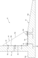
竪壁14は、底版12の凹部20における竪壁用部位20cにおいて調整板24を介して載置され、控え部材16は、凹部20における控え部位20dに配置されている。竪壁14の下面と凹部20の底面20aとの間に調整板24が介装されているので、竪壁14の下面と底版12に形成された凹部20の底面20aとの間に隙間が形成されるとともに、底板16cの下面と凹部20の底面20aとの間にも隙間が形成されている。
The
調整板24は凹部20の深さよりも薄い板材によって構成されているため、竪壁14の下面及び底板16cの下面は、凹部20内に入り込んでいる。このため、竪壁14の下端は、凹部20の側面20bに当接可能である。したがって、凹部20は、土圧を受ける竪壁14に対して剪断抵抗を付与することが可能となっている。
Since the adjusting
凹部20の内側は、無収縮モルタル36によって塞がれている。このため、竪壁14と凹部20の底面20aとの間の隙間及び控え部材16と凹部20の底面20aとの間の隙間は、無収縮モルタル36によって塞がれている。したがって、これらの隙間は露出しない。
The inside of the
本実施形態では、底版12に対する竪壁14の立設角度を調整できるようにすべく、調整手段40が設けられている。調整手段40は、竪壁14の前面側に配置された前側調整部40aと、竪壁14の背面側に配置された背面側調整部40bと、を含む。
In this embodiment, an adjusting means 40 is provided in order to be able to adjust the standing angle of the
前側調整部40aは、竪壁14に直接力を作用させて竪壁14の立設角度を調整するものであり、竪壁14の前面側に配置された調整用部材40cと、調整用部材40cに固定されたナットと、ナットに螺合され調整用部材40cに形成された挿通孔を貫通するボルト40dと、を含む。調整用部材40cは、竪壁14の前面における下端部に固定された金属製の部材によって構成されている。調整用部材38からのボルト40dの突出量を変えることにより、竪壁14の立設角度を変更することができる。
The
なお、図4に示す例では、調整用部材40cが竪壁14に固定され、前側調整部40aのボルト40dが調整用部材40cから下向きに突出する構成となっている。この構成に代え、例えば、調整用部材40cが底版12に固定されるとともに、ボルト40dが調整用部材40cから竪壁14に向けて水平方向に突出する構成であってもよい。この場合は、ボルト40dの突出量に応じて、調整用部材40cの姿勢を変えることなく竪壁14の立設角度を調整することができる。
In the example shown in FIG. 4, the
背面側調整部40bは、控え部材16に力を作用させることによって竪壁14の立設角度を調整するものであり、底板16cに固定されたナットと、ナットに螺合され底板16cに形成された挿通孔を上から下に貫通するボルトと、を含む。底板16cからのボルトの下向き突出量を変えることにより、底板16cの高さ位置を変更することができる。また、前側調整部40aのボルト40cの下向き突出量と背面側調整部40bのボルトの下向き突出量を変えることにより、底版12に対する竪壁14の立設角度を調整することができる。例えば、背面側調整部40bのボルトの下向き突出量を相対的に大きくすることにより、竪壁14を前側に向けて傾けることができ、前側調整部40aのボルト40cの下向き突出量を相対的に大きくすることにより、竪壁14を背面側に向けて傾けることができる。
The rear
ここで、擁壁ブロック10の施工方法について、図5~図9を参照しつつ説明する。まず、擁壁ブロック10の据え付け現場において、基礎工45を施工する(図5)。基礎工45は、例えば、砕石からなる層の上面をコンクリートで固めることによってレベル出しされている。
Here, a method for constructing the
工場内において予め製造された底版12を、据え付け現場に搬入する(底版搬入工程)。すなわち、底版12は、アンカーボルト26が固定されたプレキャストコンクリート製である。そして、図6に示すように、搬入された底版12を基礎工45の上に載置する(設置工程)。底版12を吊り上げて現場に搬入するには、底版12に固定された図略の吊り金具が用いられる。
The
一方、竪壁14は予め控え部材16が固定された状態で据え付け現場に搬入される。すなわち、竪壁14に控え部材16が固定された構成の擁壁部材47を、工場において予め製造しておき、図7に示すように、この擁壁部材47を据え付け現場に搬入する(擁壁部材搬入工程)。擁壁部材47を吊り上げて現場に搬入するには、竪壁14に形成された吊り孔14aが用いられる。なお、擁壁部材47には、前側調整部40a及び背面側調整部40bも取り付けられている。
On the other hand, the
次に、底版12の凹部20に調整板24を配置するとともに、調整板24の上に竪壁14が位置するように擁壁部材47を底版12に載置する(図8(a)(b)、載置工程)。載置工程では、底版12に固定されたアンカーボルト26の先端が控え部材16の底板16cに形成された挿通孔に挿通されるように擁壁部材47を位置決めし、この位置で、擁壁部材47を上から下ろす。これにより、竪壁14が凹部20の竪壁用部位20cに配置されるとともに、控え部材16が凹部20の控え部位20dに配置される。このとき、竪壁14と凹部20の底面20aとの間に隙間が形成されるとともに、控え部材16と凹部20の底面20aとの間にも隙間が形成される。
Next, the
続いて、調整手段40を操作することによって、底版12に対する竪壁14の立設角度又は竪壁14の高さ位置を調整する(調整工程)。具体的に、前側調整部40aのボルト40d及び背面側調整部40bのボルトを操作することにより、竪壁14の立設角度及び高さを調整する。これにより、複数の擁壁ブロック10を連設する場合において、隣接する擁壁ブロック10同士の竪壁14の前面を揃えることができる。
Subsequently, by operating the adjustment means 40, the angle at which the
調整作業が終われば、底版12のアンカーボルト26にナットを螺合することにより、底版12に控え部材16を接合する(接合工程)。ただし、このときは、まだ仮締めである。その後、凹部20に無収縮モルタル36を注入して(図9)、凹部20内を塞ぐ。これにより、竪壁14及び控え部材16の下側の隙間が塞がれる。その後、無収縮モルタル36が硬化した後、アンカーボルト26のナットを本締めする。これで、擁壁ブロック10の施工が完了する。なお、擁壁ブロック10の背面側には、砕石で構成される層や止水コンクリートで構成される層が設けられる。
After the adjustment work is completed, the retaining
以上説明したように、本実施形態によれば、控え部材16が鋼材で構成されているため、控え部材16がコンクリートで作成された擁壁ブロックに比べ、擁壁ブロック10としての強度を維持しつつ軽量化を図ることができる。また、コンクリート製の控え部材に比べ、控え部材16の薄型化及び小型化を図ることもできる。
As explained above, according to the present embodiment, since the retaining
また本実施形態では、底版12と竪壁14が、分離された別体の部材によって構成されているため、擁壁ブロック10の据え付け現場に擁壁ブロック10を運搬する際に、底版12と竪壁14を別個に運搬することができる。したがって、例えば20トン以上の重量となる擁壁ブロック10に好適である。
Further, in this embodiment, since the
また本実施形態では、底版12と竪壁14との間に隙間が形成されるため、擁壁部材47の鉛直度を調整する作業が煩雑になることを抑制することができる。すなわち、擁壁部材47を底版12に載置したときに、竪壁14が控え部材16と反対側(前側)にわずかに傾斜していたとしても、擁壁部材47を控え部材16側(背面側)に起立させて、竪壁14の鉛直度を調整することが可能となる。このとき、控え部材16の先端が下がるように竪壁14の姿勢が変わるが、底版12の上面と竪壁14の下面との間に隙間が形成されているため、控え部材16と底版12との干渉が生じ難い。したがって、竪壁14の鉛直度を調整する作業が煩雑になることを抑制することができる。また、控え部材16と底版12との隙間をモルタル36で塞いで、控え部材16と底版12とを密着させることができる。
Moreover, in this embodiment, since a gap is formed between the
また本実施形態では、竪壁14の下端及び控え部材16の下端が、凹部20内において調整板24とともに無収縮モルタル36に埋設された構成となっている。モルタル36が凹部20内に満たされる構成であるため、モルタル36を底版12と竪壁14との間の隙間に注入する際に型枠を用意する必要がない。したがって、モルタル36注入時の作業の手間が煩雑になることを抑制することができる。
Further, in this embodiment, the lower end of the
また本実施形態では、前面側に位置する前側調整部40a及び背面側に位置する背面側調整部40bを用いて、重量物である竪壁14の立設角度の調整を行うことができる。
Further, in this embodiment, the angle at which the
また本実施形態では、控え部材16の本体部16aの側縁から左右両側に張り出した側板16bを介して控え部材16を竪壁14に接合することができるとともに、本体部16aの底縁から左右両側に張り出した底板16cを介して控え部材16を底版12に接合することができる。本体部16aが板材で構成されるとともにこの本体部16aに側板16b及び底板16cが接合された構成であるため、控え部材16の軽量化を図りながら、控え部材16と竪壁14との接合強度及び控え部材16と底版12との接合強度を確保することができる。
Further, in this embodiment, the retaining
また控え部材16が、鋼材で作成されているので、異なる大きさの擁壁ブロック10に対して、共通化した控え部材16を取り付ける一方で、控え部材16を取り付ける枚数を異ならせることによって、強度を調整することも可能である。例えば、背の低い竪壁14を有するタイプでは、2枚の控え部材16を接合する一方で、背の高い竪壁14を有するタイプでは、4枚の控え部材16を接合する構成としてもよい。
In addition, since the retaining
また本実施形態では、控え部材16が本体部16aと底板16cとに接続されたリブ16dを備えている。このため、竪壁14に背面側からかかる土圧によって、本体部16aが底板16cから引き離される方向に本体部16aに力が加わった場合に、その力に対抗する本体部16aと底板16cとの接合強度を高めることができる。
Further, in this embodiment, the
また本実施形態では、控え部材16が頭付きスタッド部材32を介して竪壁14に固定される。頭付きスタッド部材32は竪壁14に埋設されているため、竪壁14及び控え部材16の強度計算に際し、竪壁14及び控え部材16を一体化した剛体として扱うことが可能となる。また、施工時のばらつきが生じ難い。
Further, in this embodiment, the retaining
なお、今回開示された実施形態は、すべての点で例示であって制限的なものではないと考えられるべきである。本発明は、前記実施形態に限られるものではなく、その趣旨を逸脱しない範囲で種々変更、改良等が可能である。例えば、図10に示すように、控え部材16を被覆する被覆部材50が設けられていてもよい。これにより、控え部材16が露出しない構成となるため、控え部材16を保護することができる。被覆部材50は、コンクリートによって構成されていてもよく、あるいは樹脂等によって構成されていてもよい。被覆部材50は、擁壁ブロック10の施工後に施工され、竪壁14及び底版12を一部覆っている。
Note that the embodiments disclosed this time should be considered to be illustrative in all respects and not restrictive. The present invention is not limited to the embodiments described above, and various changes and improvements can be made without departing from the spirit thereof. For example, as shown in FIG. 10, a covering
前記実施形態では、控え部材16に頭付きスタッド部材32が固定されているがこれに限られない。例えば、図11に示すように、頭付きスタッド部材32が省略される一方で、竪壁14にアンカーボルト52が固定されていてもよい。この場合、側板16bにもアンカーボルト52を挿通させる挿通孔が形成され、この挿通孔に挿通されたアンカーボルト52にナット54を螺合することにより、控え部材16を竪壁14に固定することができる。この場合、アンカーボルト52は、竪壁14の製造時に竪壁14に固定されてもよく、あるいは、擁壁ブロック10の据え付け現場において竪壁14に固定されてもよい。
In the embodiment described above, the headed
前記実施形態では、竪壁14と底版12とが分離された別体の部材によって構成されているが、これに限られるものではなく、図12に示すように、竪壁14と底版12とが一体の1つのコンクリートブロックによって構成されていてもよい。この構成では、工場内において、竪壁14及び底版12を有するコンクリートブロックに控え部材16を接合して、擁壁ブロック10を作成しておくことができる。また、竪壁14及び底版12を有するコンクリートブロックを現場に据え付けた後で、控え部材16を接合することもできる。また、底版12に対する竪壁14の立設角度を調整する作業は不要となる。このため、調整用部材38及び調整手段40は省略される。図例では、控え部材16がアンカーボルト26,52によって底版12及び竪壁14に固定される構成を示しているが、図13に示すように、控え部材16が頭付きスタッド部材32によって底版12及び竪壁14に固定される構成であってもよい。
In the embodiment described above, the
前記実施形態では、控え部材16がリブ16dを有する構成としたが、リブ16dを省略してもよい。
In the embodiment described above, the retaining
前記実施形態では、底版12の上面に凹部20が形成された構成としたが、凹部20が形成されていない構成としてもよい。この場合、調整板24が省略されて、擁壁部材47が直接底版12の上に載置されてもよい。この場合、無収縮モルタル36も不要となる。
In the embodiment described above, the
前記実施形態では、擁壁部材47に前側調整部40a及び背面側調整部40bが固定された構成としたが、これに限られない。例えば、前側調整部40aは底版12に固定されていてもよい。この場合、図14に示すように、前側調整部40aの調整用部材40cは底版12に固定される。調整用部材40cは例えばH型鋼で作成され得る。調整用部材40cは、擁壁部材47を底版12に載置する工程の前に底版12に固定される。なお、擁壁部材47を底版12に載置した後で調整用部材40cを底版12に固定してもよい。
In the embodiment described above, the
そして、擁壁部材47を底版12上に載置した後、図15(a)(b)に示すように、前側調整部40aのボルト40dを操作して竪壁14に埋設されたインサートナット56への螺合量を調整するとともに、背面側調整部40bのボルトを操作することにより、底版12に対する竪壁14の立設角度を調整する。
After placing the
図13に示す擁壁ブロック10は、底版12及び竪壁14を一体的に有する1つのコンクリートブロックによって構成されている。そして、控え部材16は、頭付きスタッド部材32を用いて底版12及び竪壁14に結合されている。これに対し、図16に示す擁壁ブロック10では、竪壁14が下側部位14bと上側部位14cとに分割されている。つまり、竪壁14は、下側部位14bと、下側部位14bと別体に形成された上側部位14cとを有し、竪壁14の下側部位14bは、底版12と一体的に形成されている。すなわち、擁壁ブロック10は、下側部位14bと底版12とが一体的に構成されたコンクリート部材58(図17)を有し、上側部位14cは、このコンクリート部材58に結合されている。そして、このコンクリート部材58に控え部材16が固定されている。すなわち、控え部材16には、側板16b及び底板16cにそれぞれ頭付きスタッド部材32が固定されており、控え部材16は、これらの頭付きスタッド部材32を介してコンクリート部材58に結合されている。なお、下側部位14bと上側部位14cとの分割線14dは、最も上に位置する頭付きスタッド部材32の固定位置よりも上側に設定されていればよい。
The retaining
上側部位14cの下端面には、鉄筋の機械式継手59を構成する筒部材59a(図19)が埋設されている。一方、下側部位14bの上端面には、鉄筋の機械式継手59を構成する鉄筋59b(図17)が突出している。そして、この下側部位14bの鉄筋59bを上側部位14cの筒部材59aに挿入し、そこにモルタルを充填するとともに上側部位14c及び下側部位14b間にモルタルが充填されることにより、上側部位14cが下側部位14bに結合されている。なお、上側部位14cと下側部位14bとの結合は、鉄筋同士を重ねて結合する重ね継手による結合であってもよく、あるいはこれ以外の結合方法を採用することもできる。また、上側部位14bに鉄筋59bを突出させ、下側部位14cに筒部材59aを埋設してもよい。
A
ここで、図16に示す擁壁ブロック10の施工方法について説明する。この擁壁ブロック10を施工するには、底版12に竪壁14の下側部位14bが一体的に形成されたコンクリート部材58に控え部材16が固定された構成の擁壁部材60(図17)を用意する。この擁壁部材60を作成するには、竪壁14の下側部位14b及び底版12を有するコンクリート部材58を成形する際に、控え部材16に固定された頭付きスタッド部材32がコンクリート部材58に埋設されるように、コンクリート部材58を成形する。
Here, a construction method for the
そして、この擁壁部材60を据え付け現場に搬入し(搬入工程)、図18に示すように、擁壁部材60を所定の場所に設置する(設置工程)。続いて、図19に示すように、竪壁14の上側部位14cを据え付け現場に搬入するとともに、この上側部位14cを、設置された擁壁部材60の下側部位14bの上に載置する(載置工程)。このとき、下側部位14bの上端面から突出している鉄筋59bを上側部位14cの下端面に埋設された筒部材59aに挿入する。
Then, this retaining
続いて、竪壁14の下側部位14bに竪壁14の上側部位14cを固定する(固定工程)。この固定工程では、図20に示すように、仮固定材62を用いる。仮固定材62は、L型アングル又はH型鋼からなり、この仮固定材62を下側部位14bと上側部位14cとに跨がるように、竪壁14の前面及び背面に配置する。このとき、図略のボルトを仮固定材62に形成された貫通孔に挿通するとともに、竪壁14に設けられたナットに締結することにより、仮固定材62を竪壁14に固定する。そして、上側部位14cと下側部位14bとの間の隙間にモルタルを充填する。モルタルが固化した後は、仮固定材62を撤去する。
Subsequently, the
続いて、図21に示すように、控え部材16を被覆部材50で被覆できるように、型枠64を控え部材16に固定する。このとき、被覆部材50内に水抜きパイプ66が配置されるように、水抜きパイプ66を固定しておく。そして、型枠64内にコンクリートを流し込み、被覆部材50を形成する。コンクリートが固まれば、型枠64を取り外し、必要に応じて、図略の土粒子止めフィルターを配設するとともに図略の止水コンクリートを打設する。
Subsequently, as shown in FIG. 21, the
10 :擁壁ブロック
12 :底版
14 :竪壁
14b :下側部位
14c :上側部位
16 :控え部材
16a :本体部
16b :側板
16c :底板
16d :リブ
20 :凹部
24 :調整板
26 :アンカーボルト
32 :頭付きスタッド部材
36 :無収縮モルタル
40 :調整手段
40a :前側調整部
40b :背面側調整部
47 :擁壁部材
50 :被覆部材
52 :アンカーボルト
54 :ナット
58 :コンクリート部材
60 :擁壁部材
10: Retaining wall block 12: Bottom plate 14:
Claims (13)
前記底版から立ち上がる竪壁と、
前記底版の上側で且つ前記竪壁の背面側に位置し、前記底版及び前記竪壁に接合された控え部材と、を備え、
前記底版及び前記竪壁はコンクリート製であり、
前記控え部材は、鋼材で構成され、
前記底版と前記竪壁は、分離された別体の部材によって構成されており、
前記竪壁の前面側に配置された前側調整部と、前記竪壁の背面側に配置された背面側調整部と、を含み、前記底版に対する前記竪壁の立設角度及び高さ位置の少なくとも一方を変えられる調整手段が設けられ、
前記前側調整部は、前記竪壁の前面側で且つ前記底版の上側に配置された調整用部材と、前記立設角度及び前記高さ位置のうち少なくとも前記立設角度が調整されるように前記調整用部材からの突出量を変更可能な部材と、を含む擁壁ブロック。 The bottom plate and
a vertical wall rising from the bottom plate;
a retaining member located above the bottom plate and on the back side of the vertical wall and joined to the bottom plate and the vertical wall,
The bottom plate and the vertical wall are made of concrete,
The retainer member is made of steel ,
The bottom plate and the vertical wall are constituted by separate members,
a front side adjustment section disposed on the front side of the vertical wall; and a rear side adjustment section disposed on the back side of the vertical wall, and at least the angle and height position of the vertical wall relative to the bottom plate are adjusted. An adjustment means is provided to change one side,
The front adjustment part includes an adjustment member disposed on the front side of the vertical wall and above the bottom plate, and the adjustment member configured to adjust the upright angle so that at least the upright angle of the upright angle and the height position is adjusted. A retaining wall block including a member whose protrusion amount from an adjustment member can be changed .
前記底版から立ち上がる竪壁と、
前記底版の上側で且つ前記竪壁の背面側に位置し、前記底版及び前記竪壁に接合された控え部材と、を備え、
前記底版及び前記竪壁はコンクリート製であり、
前記控え部材は、鋼材で構成され、
前記底版と前記竪壁は、分離された別体の部材によって構成されており、
前記竪壁の前面側に配置された前側調整部と、前記竪壁の背面側に配置された背面側調整部と、を含み、前記底版に対する前記竪壁の立設角度及び高さ位置の少なくとも一方を変えられる調整手段が設けられ、
前記背面側調整部は、前記控え部材に固定されたナットと、前記ナットに螺合され且つ前記立設角度及び前記高さ位置のうち少なくとも前記立設角度が調整されるように突出量を変更可能なボルトと、を含む擁壁ブロック。 The bottom plate and
a vertical wall rising from the bottom plate;
a retaining member located above the bottom plate and on the back side of the vertical wall and joined to the bottom plate and the vertical wall,
The bottom plate and the vertical wall are made of concrete,
The retainer member is made of steel,
The bottom plate and the vertical wall are constituted by separate members,
a front side adjustment section disposed on the front side of the vertical wall; and a rear side adjustment section disposed on the back side of the vertical wall, and at least the angle and height position of the vertical wall relative to the bottom plate are adjusted. An adjustment means is provided to change one side,
The rear side adjustment part is screwed into a nut fixed to the retaining member, and changes a protrusion amount so that at least the upright angle of the upright angle and the height position is adjusted. Retaining wall block including possible bolts and .
前記隙間はモルタルによって塞がれている請求項1又は2に記載の擁壁ブロック。 By disposing an adjustment plate between the bottom plate and the vertical wall, a gap is formed between the bottom plate and the vertical wall and the retaining member,
The retaining wall block according to claim 1 or 2, wherein the gap is closed with mortar.
前記竪壁及び前記控え部材は、前記凹部に載置され、
前記モルタルは前記凹部内を埋めている請求項3に記載の擁壁ブロック。 A recess is formed on the upper surface of the bottom plate,
The vertical wall and the retaining member are placed in the recess,
The retaining wall block according to claim 3, wherein the mortar fills the inside of the recess.
前記側板は、前記頭付きスタッド部材を介して前記竪壁に結合されている請求項5又は6に記載の擁壁ブロック。 A headed stud member is fixed to the vertical wall,
The retaining wall block according to claim 5 or 6 , wherein the side plate is coupled to the vertical wall via the headed stud member.
前記控え部材は、前記側板に挿通されたアンカーボルトにナットを締め付けることによって前記竪壁に接合されている請求項5又は6に記載の擁壁ブロック。 An anchor bolt is fixed to the vertical wall,
7. The retaining wall block according to claim 5 , wherein the retaining member is joined to the vertical wall by tightening a nut on an anchor bolt inserted through the side plate.
コンクリート製の竪壁と、
鋼材で構成され、前記竪壁の背面に接合された控え部材と、を備えている擁壁部材。 A retaining wall member used in the retaining wall block according to any one of claims 1 to 9,
concrete vertical wall,
A retaining wall member comprising a retaining member made of steel and joined to the back surface of the vertical wall.
前記底版を所定の場所に載置する設置工程と、
前記所定の場所に載置された前記底版に、前記擁壁部材の前記控え部材を接合する接合工程と、
前記底版に対する前記竪壁の立設角度及び高さ位置の少なくとも一方を調整する調整工程と、を含み、
前記調整工程では、前記竪壁の前面側で且つ前記底版の上側に配置された調整用部材と、前記調整用部材に対する突出量を変更可能な部材と、を用い、前記調整用部材に対する前記部材の突出量を変更することにより、前記立設角度及び前記高さ位置のうち少なくとも前記立設角度を調整する擁壁ブロックの施工方法。 A carrying process of carrying a retaining wall member including a vertical wall made of concrete and a retaining member made of steel material and joined to the vertical wall to the installation site of the retaining wall block, and carrying the bottom slab to the installation site. and,
an installation step of placing the bottom plate in a predetermined location;
a joining step of joining the retaining member of the retaining wall member to the bottom plate placed at the predetermined location;
an adjustment step of adjusting at least one of the standing angle and height position of the vertical wall with respect to the bottom plate ,
In the adjustment step, an adjustment member disposed on the front side of the vertical wall and above the bottom plate, and a member whose protrusion amount with respect to the adjustment member can be changed, are used, and the member with respect to the adjustment member is used. A method for constructing a retaining wall block , wherein at least the erecting angle of the erecting angle and the height position is adjusted by changing the amount of protrusion of the retaining wall block.
前記底版を所定の場所に載置する設置工程と、 an installation step of placing the bottom plate in a predetermined location;
前記所定の場所に載置された前記底版に、前記擁壁部材の前記控え部材を接合する接合工程と、 a joining step of joining the retaining member of the retaining wall member to the bottom plate placed at the predetermined location;
前記底版に対する前記竪壁の立設角度及び高さ位置の少なくとも一方を調整する調整工程と、を含み、 an adjustment step of adjusting at least one of the standing angle and height position of the vertical wall with respect to the bottom plate,
前記調整工程では、前記控え部材に固定されたナットと、前記ナットに螺合されて突出量を変更可能なボルトと、を用い、前記ボルトの突出量を調整することにより、前記立設角度及び前記高さ位置のうち少なくとも前記立設角度を調整する擁壁ブロックの施工方法。 In the adjustment step, the upright angle and A method for constructing a retaining wall block in which at least the erection angle of the height position is adjusted.
Applications Claiming Priority (2)
| Application Number | Priority Date | Filing Date | Title |
|---|---|---|---|
| JP2019188857 | 2019-10-15 | ||
| JP2019188857 | 2019-10-15 |
Publications (2)
| Publication Number | Publication Date |
|---|---|
| JP2021063426A JP2021063426A (en) | 2021-04-22 |
| JP7444397B2 true JP7444397B2 (en) | 2024-03-06 |
Family
ID=75487776
Family Applications (1)
| Application Number | Title | Priority Date | Filing Date |
|---|---|---|---|
| JP2020171190A Active JP7444397B2 (en) | 2019-10-15 | 2020-10-09 | Construction method for retaining wall blocks, retaining wall members, and retaining wall blocks |
Country Status (1)
| Country | Link |
|---|---|
| JP (1) | JP7444397B2 (en) |
Citations (12)
| Publication number | Priority date | Publication date | Assignee | Title |
|---|---|---|---|---|
| JP2000179053A (en) | 1998-12-18 | 2000-06-27 | Kaieitechno Co Ltd | Connecting metal |
| JP2001040683A (en) | 1999-07-30 | 2001-02-13 | Daiwa-Cres Co Ltd | Resting type assembly retaining wall |
| JP2001131994A (en) | 1999-10-29 | 2001-05-15 | Fujibayashi Concrete Kogyo Kk | Installation method for large concrete block product |
| JP2001173137A (en) | 1999-12-14 | 2001-06-26 | Takamura Sogyo Kk | Left-in-place-formwork |
| JP2001214461A (en) | 2000-02-02 | 2001-08-07 | Sekisui House Ltd | Retaining wall |
| JP2004238984A (en) | 2003-02-07 | 2004-08-26 | Kyowa Concrete Industry Co Ltd | Retaining wall panel, and bubble mixed lightweight banking method |
| JP2006083697A (en) | 2005-10-31 | 2006-03-30 | Kyokado Eng Co Ltd | Reinforced earth structure and wall surface block |
| JP2006118353A (en) | 2006-01-05 | 2006-05-11 | Tokyu Construction Co Ltd | Method of designing concrete structure |
| JP2012046980A (en) | 2010-08-27 | 2012-03-08 | Kumagai Gumi Co Ltd | Building foundation using earth retaining wall |
| JP2014088732A (en) | 2012-10-31 | 2014-05-15 | Daito Trust Construction Co Ltd | Method for constructing steel pipe pile, and steel pipe pile member |
| JP2016515173A (en) | 2013-03-15 | 2016-05-26 | ユーティリティ コンクリート プロダクツ,エルエルシー | Precast concrete retaining wall |
| JP2019078065A (en) | 2017-10-24 | 2019-05-23 | 株式会社ニッコン | Laying method of cantilever-type retaining wall |
-
2020
- 2020-10-09 JP JP2020171190A patent/JP7444397B2/en active Active
Patent Citations (12)
| Publication number | Priority date | Publication date | Assignee | Title |
|---|---|---|---|---|
| JP2000179053A (en) | 1998-12-18 | 2000-06-27 | Kaieitechno Co Ltd | Connecting metal |
| JP2001040683A (en) | 1999-07-30 | 2001-02-13 | Daiwa-Cres Co Ltd | Resting type assembly retaining wall |
| JP2001131994A (en) | 1999-10-29 | 2001-05-15 | Fujibayashi Concrete Kogyo Kk | Installation method for large concrete block product |
| JP2001173137A (en) | 1999-12-14 | 2001-06-26 | Takamura Sogyo Kk | Left-in-place-formwork |
| JP2001214461A (en) | 2000-02-02 | 2001-08-07 | Sekisui House Ltd | Retaining wall |
| JP2004238984A (en) | 2003-02-07 | 2004-08-26 | Kyowa Concrete Industry Co Ltd | Retaining wall panel, and bubble mixed lightweight banking method |
| JP2006083697A (en) | 2005-10-31 | 2006-03-30 | Kyokado Eng Co Ltd | Reinforced earth structure and wall surface block |
| JP2006118353A (en) | 2006-01-05 | 2006-05-11 | Tokyu Construction Co Ltd | Method of designing concrete structure |
| JP2012046980A (en) | 2010-08-27 | 2012-03-08 | Kumagai Gumi Co Ltd | Building foundation using earth retaining wall |
| JP2014088732A (en) | 2012-10-31 | 2014-05-15 | Daito Trust Construction Co Ltd | Method for constructing steel pipe pile, and steel pipe pile member |
| JP2016515173A (en) | 2013-03-15 | 2016-05-26 | ユーティリティ コンクリート プロダクツ,エルエルシー | Precast concrete retaining wall |
| JP2019078065A (en) | 2017-10-24 | 2019-05-23 | 株式会社ニッコン | Laying method of cantilever-type retaining wall |
Also Published As
| Publication number | Publication date |
|---|---|
| JP2021063426A (en) | 2021-04-22 |
Similar Documents
| Publication | Publication Date | Title |
|---|---|---|
| US8789337B2 (en) | Foundation system for bridges and other structures | |
| US11661719B2 (en) | Building elements for making retaining walls, and systems and methods of using same | |
| US20150322635A1 (en) | Foundation system for bridges and other structures | |
| KR20160001216A (en) | Rahmen using hinge type pc wall and method for constructing the same | |
| JP3569878B2 (en) | Jig for connecting precast concrete slabs | |
| KR101211469B1 (en) | Retaining wall structure having prefabricated block and method for constructing retaining wall using the same | |
| JP6644600B2 (en) | Integrated foundation and integrated foundation method | |
| JP7444397B2 (en) | Construction method for retaining wall blocks, retaining wall members, and retaining wall blocks | |
| JP2020197015A (en) | Construction method of foundation | |
| JP2009046942A (en) | Foundation block for retaining wall | |
| JPH09151463A (en) | Column-integrated column base anchoring foundation structire and work execution method therefor | |
| JP7121486B2 (en) | foundation structure | |
| KR101544985B1 (en) | Socket type precast concrete panel and paving method using the same | |
| JP4726260B2 (en) | Overhang sidewalk structure | |
| JP6388419B1 (en) | 方法 Installation method and structure | |
| JP4127020B2 (en) | Vertical embankment method and retaining wall used in this method | |
| JP3363554B2 (en) | Construction method of concrete building | |
| KR200212405Y1 (en) | Precast concrete segment for arch type culvert | |
| KR101650312B1 (en) | Concrete retaining wall and method for manufacturing the same | |
| KR20020009116A (en) | Precast concrete segment for arch type culvert and construction method using this segment | |
| JP3593752B2 (en) | Retaining wall structure and built flat land structure or built road structure on steep slopes | |
| JP3002026B2 (en) | Structure of residential continuous foundation | |
| CA3080176A1 (en) | Building elements for making retaining walls, and systems and methods of using same | |
| GB2152973A (en) | Method of building a cavity structure in an embankment | |
| JP2004232431A (en) | Channel block having earth retaining function |
Legal Events
| Date | Code | Title | Description |
|---|---|---|---|
| A621 | Written request for application examination |
Free format text: JAPANESE INTERMEDIATE CODE: A621 Effective date: 20221201 |
|
| A977 | Report on retrieval |
Free format text: JAPANESE INTERMEDIATE CODE: A971007 Effective date: 20230808 |
|
| A131 | Notification of reasons for refusal |
Free format text: JAPANESE INTERMEDIATE CODE: A131 Effective date: 20230822 |
|
| A521 | Request for written amendment filed |
Free format text: JAPANESE INTERMEDIATE CODE: A523 Effective date: 20231020 |
|
| TRDD | Decision of grant or rejection written | ||
| A01 | Written decision to grant a patent or to grant a registration (utility model) |
Free format text: JAPANESE INTERMEDIATE CODE: A01 Effective date: 20240123 |
|
| A61 | First payment of annual fees (during grant procedure) |
Free format text: JAPANESE INTERMEDIATE CODE: A61 Effective date: 20240214 |
|
| R150 | Certificate of patent or registration of utility model |
Ref document number: 7444397 Country of ref document: JP Free format text: JAPANESE INTERMEDIATE CODE: R150 |