JP7439380B2 - tube container - Google Patents
tube container Download PDFInfo
- Publication number
- JP7439380B2 JP7439380B2 JP2018243758A JP2018243758A JP7439380B2 JP 7439380 B2 JP7439380 B2 JP 7439380B2 JP 2018243758 A JP2018243758 A JP 2018243758A JP 2018243758 A JP2018243758 A JP 2018243758A JP 7439380 B2 JP7439380 B2 JP 7439380B2
- Authority
- JP
- Japan
- Prior art keywords
- layer
- tube container
- laminate
- base
- cylindrical body
- Prior art date
- Legal status (The legal status is an assumption and is not a legal conclusion. Google has not performed a legal analysis and makes no representation as to the accuracy of the status listed.)
- Active
Links
- 239000010410 layer Substances 0.000 claims description 249
- 239000000565 sealant Substances 0.000 claims description 45
- 229920000139 polyethylene terephthalate Polymers 0.000 claims description 41
- 239000005020 polyethylene terephthalate Substances 0.000 claims description 41
- 229920000092 linear low density polyethylene Polymers 0.000 claims description 38
- 239000004707 linear low-density polyethylene Substances 0.000 claims description 38
- 229920001684 low density polyethylene Polymers 0.000 claims description 37
- 239000004702 low-density polyethylene Substances 0.000 claims description 37
- 238000007639 printing Methods 0.000 claims description 33
- 239000011241 protective layer Substances 0.000 claims description 33
- 239000000463 material Substances 0.000 claims description 32
- 239000002966 varnish Substances 0.000 claims description 23
- -1 polyethylene terephthalate Polymers 0.000 claims description 17
- 239000004677 Nylon Substances 0.000 claims description 8
- 229920001778 nylon Polymers 0.000 claims description 8
- 230000003068 static effect Effects 0.000 claims description 4
- 239000012752 auxiliary agent Substances 0.000 claims description 2
- 239000000203 mixture Substances 0.000 claims description 2
- 239000000178 monomer Substances 0.000 claims description 2
- NLZUEZXRPGMBCV-UHFFFAOYSA-N Butylhydroxytoluene Chemical compound CC1=CC(C(C)(C)C)=C(O)C(C(C)(C)C)=C1 NLZUEZXRPGMBCV-UHFFFAOYSA-N 0.000 claims 1
- 239000003999 initiator Substances 0.000 claims 1
- DOIRQSBPFJWKBE-UHFFFAOYSA-N phthalic acid di-n-butyl ester Natural products CCCCOC(=O)C1=CC=CC=C1C(=O)OCCCC DOIRQSBPFJWKBE-UHFFFAOYSA-N 0.000 claims 1
- 230000004888 barrier function Effects 0.000 description 40
- 238000000034 method Methods 0.000 description 28
- 238000012360 testing method Methods 0.000 description 23
- 229910052751 metal Inorganic materials 0.000 description 18
- 239000002184 metal Substances 0.000 description 18
- 229920005989 resin Polymers 0.000 description 15
- 239000011347 resin Substances 0.000 description 15
- 238000004519 manufacturing process Methods 0.000 description 14
- 229910052782 aluminium Inorganic materials 0.000 description 13
- XAGFODPZIPBFFR-UHFFFAOYSA-N aluminium Chemical compound [Al] XAGFODPZIPBFFR-UHFFFAOYSA-N 0.000 description 13
- 230000000052 comparative effect Effects 0.000 description 13
- 239000011247 coating layer Substances 0.000 description 12
- 229920005648 ethylene methacrylic acid copolymer Polymers 0.000 description 12
- 239000011888 foil Substances 0.000 description 12
- 238000004806 packaging method and process Methods 0.000 description 12
- 229920002799 BoPET Polymers 0.000 description 11
- 239000012790 adhesive layer Substances 0.000 description 10
- 238000009820 dry lamination Methods 0.000 description 8
- 239000004698 Polyethylene Substances 0.000 description 6
- VYPSYNLAJGMNEJ-UHFFFAOYSA-N Silicium dioxide Chemical compound O=[Si]=O VYPSYNLAJGMNEJ-UHFFFAOYSA-N 0.000 description 6
- 238000003854 Surface Print Methods 0.000 description 6
- 238000007646 gravure printing Methods 0.000 description 6
- 238000005259 measurement Methods 0.000 description 6
- 229920000573 polyethylene Polymers 0.000 description 6
- 101000793686 Homo sapiens Azurocidin Proteins 0.000 description 5
- 239000002537 cosmetic Substances 0.000 description 5
- 238000013461 design Methods 0.000 description 5
- 238000003475 lamination Methods 0.000 description 5
- 239000004743 Polypropylene Substances 0.000 description 4
- 238000010030 laminating Methods 0.000 description 4
- TWNQGVIAIRXVLR-UHFFFAOYSA-N oxo(oxoalumanyloxy)alumane Chemical compound O=[Al]O[Al]=O TWNQGVIAIRXVLR-UHFFFAOYSA-N 0.000 description 4
- 229920001155 polypropylene Polymers 0.000 description 4
- VGGSQFUCUMXWEO-UHFFFAOYSA-N Ethene Chemical compound C=C VGGSQFUCUMXWEO-UHFFFAOYSA-N 0.000 description 3
- 239000005977 Ethylene Substances 0.000 description 3
- PNEYBMLMFCGWSK-UHFFFAOYSA-N aluminium oxide Inorganic materials [O-2].[O-2].[O-2].[Al+3].[Al+3] PNEYBMLMFCGWSK-UHFFFAOYSA-N 0.000 description 3
- 238000000748 compression moulding Methods 0.000 description 3
- 238000001816 cooling Methods 0.000 description 3
- 238000011156 evaluation Methods 0.000 description 3
- 238000001746 injection moulding Methods 0.000 description 3
- 229920005672 polyolefin resin Polymers 0.000 description 3
- 238000007789 sealing Methods 0.000 description 3
- 239000000377 silicon dioxide Substances 0.000 description 3
- 238000007740 vapor deposition Methods 0.000 description 3
- 229920000219 Ethylene vinyl alcohol Polymers 0.000 description 2
- YCKRFDGAMUMZLT-UHFFFAOYSA-N Fluorine atom Chemical compound [F] YCKRFDGAMUMZLT-UHFFFAOYSA-N 0.000 description 2
- VZCYOOQTPOCHFL-OWOJBTEDSA-N Fumaric acid Chemical compound OC(=O)\C=C\C(O)=O VZCYOOQTPOCHFL-OWOJBTEDSA-N 0.000 description 2
- 229920000122 acrylonitrile butadiene styrene Polymers 0.000 description 2
- 239000011248 coating agent Substances 0.000 description 2
- 229920001577 copolymer Polymers 0.000 description 2
- 238000005520 cutting process Methods 0.000 description 2
- 229920006242 ethylene acrylic acid copolymer Polymers 0.000 description 2
- 230000008020 evaporation Effects 0.000 description 2
- 238000001704 evaporation Methods 0.000 description 2
- 238000001125 extrusion Methods 0.000 description 2
- 239000004744 fabric Substances 0.000 description 2
- 238000005429 filling process Methods 0.000 description 2
- 239000011737 fluorine Substances 0.000 description 2
- 229910052731 fluorine Inorganic materials 0.000 description 2
- 229920001903 high density polyethylene Polymers 0.000 description 2
- 239000004700 high-density polyethylene Substances 0.000 description 2
- 238000005304 joining Methods 0.000 description 2
- 229920001179 medium density polyethylene Polymers 0.000 description 2
- 239000004701 medium-density polyethylene Substances 0.000 description 2
- 229920003145 methacrylic acid copolymer Polymers 0.000 description 2
- 229940117841 methacrylic acid copolymer Drugs 0.000 description 2
- 238000012858 packaging process Methods 0.000 description 2
- 229920002239 polyacrylonitrile Polymers 0.000 description 2
- 229920001225 polyester resin Polymers 0.000 description 2
- 239000004645 polyester resin Substances 0.000 description 2
- 229920005990 polystyrene resin Polymers 0.000 description 2
- 229910001220 stainless steel Inorganic materials 0.000 description 2
- 239000010935 stainless steel Substances 0.000 description 2
- VZCYOOQTPOCHFL-UHFFFAOYSA-N trans-butenedioic acid Natural products OC(=O)C=CC(O)=O VZCYOOQTPOCHFL-UHFFFAOYSA-N 0.000 description 2
- DHKHKXVYLBGOIT-UHFFFAOYSA-N 1,1-Diethoxyethane Chemical compound CCOC(C)OCC DHKHKXVYLBGOIT-UHFFFAOYSA-N 0.000 description 1
- SMZOUWXMTYCWNB-UHFFFAOYSA-N 2-(2-methoxy-5-methylphenyl)ethanamine Chemical compound COC1=CC=C(C)C=C1CCN SMZOUWXMTYCWNB-UHFFFAOYSA-N 0.000 description 1
- JAHNSTQSQJOJLO-UHFFFAOYSA-N 2-(3-fluorophenyl)-1h-imidazole Chemical compound FC1=CC=CC(C=2NC=CN=2)=C1 JAHNSTQSQJOJLO-UHFFFAOYSA-N 0.000 description 1
- BLDFSDCBQJUWFG-UHFFFAOYSA-N 2-(methylamino)-1,2-diphenylethanol Chemical compound C=1C=CC=CC=1C(NC)C(O)C1=CC=CC=C1 BLDFSDCBQJUWFG-UHFFFAOYSA-N 0.000 description 1
- NIXOWILDQLNWCW-UHFFFAOYSA-N 2-Propenoic acid Natural products OC(=O)C=C NIXOWILDQLNWCW-UHFFFAOYSA-N 0.000 description 1
- JMMZCWZIJXAGKW-UHFFFAOYSA-N 2-methylpent-2-ene Chemical compound CCC=C(C)C JMMZCWZIJXAGKW-UHFFFAOYSA-N 0.000 description 1
- 229920002126 Acrylic acid copolymer Polymers 0.000 description 1
- 229920000178 Acrylic resin Polymers 0.000 description 1
- 239000004925 Acrylic resin Substances 0.000 description 1
- 244000056139 Brassica cretica Species 0.000 description 1
- 235000003351 Brassica cretica Nutrition 0.000 description 1
- 235000003343 Brassica rupestris Nutrition 0.000 description 1
- 229920010126 Linear Low Density Polyethylene (LLDPE) Polymers 0.000 description 1
- CERQOIWHTDAKMF-UHFFFAOYSA-N Methacrylic acid Chemical compound CC(=C)C(O)=O CERQOIWHTDAKMF-UHFFFAOYSA-N 0.000 description 1
- 229920000007 Nylon MXD6 Polymers 0.000 description 1
- 239000004962 Polyamide-imide Substances 0.000 description 1
- 239000004695 Polyether sulfone Substances 0.000 description 1
- 239000004734 Polyphenylene sulfide Substances 0.000 description 1
- OFOBLEOULBTSOW-UHFFFAOYSA-N Propanedioic acid Natural products OC(=O)CC(O)=O OFOBLEOULBTSOW-UHFFFAOYSA-N 0.000 description 1
- 244000195452 Wasabia japonica Species 0.000 description 1
- 235000000760 Wasabia japonica Nutrition 0.000 description 1
- 239000011354 acetal resin Substances 0.000 description 1
- XECAHXYUAAWDEL-UHFFFAOYSA-N acrylonitrile butadiene styrene Chemical compound C=CC=C.C=CC#N.C=CC1=CC=CC=C1 XECAHXYUAAWDEL-UHFFFAOYSA-N 0.000 description 1
- 239000004676 acrylonitrile butadiene styrene Substances 0.000 description 1
- 229920001893 acrylonitrile styrene Polymers 0.000 description 1
- 230000015572 biosynthetic process Effects 0.000 description 1
- QKSKPIVNLNLAAV-UHFFFAOYSA-N bis(2-chloroethyl) sulfide Chemical compound ClCCSCCCl QKSKPIVNLNLAAV-UHFFFAOYSA-N 0.000 description 1
- 230000000903 blocking effect Effects 0.000 description 1
- 150000001735 carboxylic acids Chemical class 0.000 description 1
- 239000012461 cellulose resin Substances 0.000 description 1
- 238000003851 corona treatment Methods 0.000 description 1
- 125000004122 cyclic group Chemical group 0.000 description 1
- 230000007423 decrease Effects 0.000 description 1
- 230000008021 deposition Effects 0.000 description 1
- 230000006866 deterioration Effects 0.000 description 1
- 230000000694 effects Effects 0.000 description 1
- 239000005038 ethylene vinyl acetate Substances 0.000 description 1
- 239000004715 ethylene vinyl alcohol Substances 0.000 description 1
- 229920006244 ethylene-ethyl acrylate Polymers 0.000 description 1
- 239000010408 film Substances 0.000 description 1
- 239000001530 fumaric acid Substances 0.000 description 1
- 238000009957 hemming Methods 0.000 description 1
- 230000005764 inhibitory process Effects 0.000 description 1
- 229920000554 ionomer Polymers 0.000 description 1
- VZCYOOQTPOCHFL-UPHRSURJSA-N maleic acid Chemical compound OC(=O)\C=C/C(O)=O VZCYOOQTPOCHFL-UPHRSURJSA-N 0.000 description 1
- 239000011976 maleic acid Substances 0.000 description 1
- FPYJFEHAWHCUMM-UHFFFAOYSA-N maleic anhydride Chemical compound O=C1OC(=O)C=C1 FPYJFEHAWHCUMM-UHFFFAOYSA-N 0.000 description 1
- LVHBHZANLOWSRM-UHFFFAOYSA-N methylenebutanedioic acid Natural products OC(=O)CC(=C)C(O)=O LVHBHZANLOWSRM-UHFFFAOYSA-N 0.000 description 1
- 235000010460 mustard Nutrition 0.000 description 1
- XNGIFLGASWRNHJ-UHFFFAOYSA-L phthalate(2-) Chemical compound [O-]C(=O)C1=CC=CC=C1C([O-])=O XNGIFLGASWRNHJ-UHFFFAOYSA-L 0.000 description 1
- 229920003207 poly(ethylene-2,6-naphthalate) Polymers 0.000 description 1
- 229920001200 poly(ethylene-vinyl acetate) Polymers 0.000 description 1
- 229920002492 poly(sulfone) Polymers 0.000 description 1
- 229920006122 polyamide resin Polymers 0.000 description 1
- 229920002312 polyamide-imide Polymers 0.000 description 1
- 229920005668 polycarbonate resin Polymers 0.000 description 1
- 239000004431 polycarbonate resin Substances 0.000 description 1
- 229920006393 polyether sulfone Polymers 0.000 description 1
- 239000011112 polyethylene naphthalate Substances 0.000 description 1
- 229920013716 polyethylene resin Polymers 0.000 description 1
- 229920001721 polyimide Polymers 0.000 description 1
- 239000009719 polyimide resin Substances 0.000 description 1
- 229920000642 polymer Polymers 0.000 description 1
- 229920000098 polyolefin Polymers 0.000 description 1
- 229920006324 polyoxymethylene Polymers 0.000 description 1
- 229920000069 polyphenylene sulfide Polymers 0.000 description 1
- 229920002635 polyurethane Polymers 0.000 description 1
- 239000004814 polyurethane Substances 0.000 description 1
- 229920005749 polyurethane resin Polymers 0.000 description 1
- 239000011118 polyvinyl acetate Substances 0.000 description 1
- 229920002689 polyvinyl acetate Polymers 0.000 description 1
- 239000004800 polyvinyl chloride Substances 0.000 description 1
- 229920000915 polyvinyl chloride Polymers 0.000 description 1
- 239000005033 polyvinylidene chloride Substances 0.000 description 1
- SCUZVMOVTVSBLE-UHFFFAOYSA-N prop-2-enenitrile;styrene Chemical compound C=CC#N.C=CC1=CC=CC=C1 SCUZVMOVTVSBLE-UHFFFAOYSA-N 0.000 description 1
- 238000003847 radiation curing Methods 0.000 description 1
- 230000001105 regulatory effect Effects 0.000 description 1
- 230000003252 repetitive effect Effects 0.000 description 1
- 230000002441 reversible effect Effects 0.000 description 1
- 229920002050 silicone resin Polymers 0.000 description 1
- 230000004936 stimulating effect Effects 0.000 description 1
- 238000004381 surface treatment Methods 0.000 description 1
- 229920003002 synthetic resin Polymers 0.000 description 1
- 239000000057 synthetic resin Substances 0.000 description 1
- 238000012546 transfer Methods 0.000 description 1
- XLYOFNOQVPJJNP-UHFFFAOYSA-N water Substances O XLYOFNOQVPJJNP-UHFFFAOYSA-N 0.000 description 1
Images

Description
本願発明はチューブ容器に関し、より詳しくは、外部の物体と接触した際に、容器の外面に耐傷性を有するチューブ容器に関する。 TECHNICAL FIELD The present invention relates to a tube container, and more particularly to a tube container that has scratch resistance on the outer surface of the container when it comes into contact with an external object.
従来のチューブ容器、特にラミネートチューブ容器の外面は、ポリエチレンを代表とするポリオレフィンが使用されており、前記ラミネートチューブ容器の外面に印刷されるものは少ない。印刷は、中間層となるポリエチレンテレフタレートフィルムなどの内面に印刷されることが多い。特許文献1および特許文献2参照。
印刷されていない外面のポリエチレン層の表面は柔らかく、外部の硬質な物体と擦れると、傷が生じやすい。
The outer surface of conventional tube containers, especially laminate tube containers, is made of polyolefin, typically polyethylene, and there is little printing on the outer surface of the laminate tube containers. Printing is often done on the inner surface of polyethylene terephthalate film, which serves as an intermediate layer. See Patent Document 1 and Patent Document 2.
The surface of the unprinted outer polyethylene layer is soft and prone to scratches when rubbed against hard external objects.
チューブ容器に内容物を充填して密封するチューブ容器の包装製品の製造ラインにおいては、空チューブ容器の搬送の時や、充填・包装工程中や、充填・包装工程完了後のいずれの工程においても、チューブ容器を搬送する必要があり、搬送コンベアの上にてガイドなどと接触し、擦れることとなる。また、充填・包装装置内でも、装置内の各工程でのチューブ容器を固定する冶具に接触したり、各工程間の移送時でも、各種ハンドリング装置と接触して、チューブ容器の外面が傷つくことがある。 In the manufacturing line for tube container packaging products, in which tube containers are filled with contents and sealed, there are , it is necessary to transport the tube container, and it comes into contact with guides and the like on the transport conveyor, causing friction. In addition, even within the filling/packaging equipment, the outer surface of the tube container may be damaged due to contact with the jigs that fix the tube container in each process within the equipment, or contact with various handling devices during transfer between each process. There is.
本願発明はこのような状況を鑑みてなされたものであって、チューブ容器の外面の耐傷性を向上させ、上記のようなチューブ容器の充填・包装工程において、チューブ容器の外面に傷がつかず、美粧性を保つことができるチューブ容器を提供することを目的とする。 The present invention was made in view of this situation, and it improves the scratch resistance of the outer surface of the tube container, and prevents the outer surface of the tube container from being damaged during the filling and packaging process of the tube container as described above. The purpose of the present invention is to provide a tube container that can maintain its cosmetic appearance.
本願発明のチューブ容器は、一対の貼り合わせ端部を有する胴部と、肩部からなるチューブ容器において、前記胴部の積層体は、外面から内面に向かって、少なくとも、第一基材層、第二基材層、第二シーラント層がこの順に積層され、さらに前記第一基材層の外面の全面もしくは少なくとも一部に保護層が設けられていることを特徴としている。 The tube container of the present invention includes a body having a pair of bonded ends and a shoulder, in which the laminate of the body has at least a first base layer, A second base material layer and a second sealant layer are laminated in this order, and a protective layer is further provided on the entire or at least part of the outer surface of the first base layer.
前記チューブ容器の筒状胴部の外面に保護層を備えることにより、耐傷性が向上する。また、前記チューブ容器の筒状胴部の外面の摩擦係数が低下する。 By providing a protective layer on the outer surface of the cylindrical body of the tube container, scratch resistance is improved. Furthermore, the coefficient of friction of the outer surface of the cylindrical body of the tube container is reduced.
本願発明によれば、チューブ容器の外面の耐傷性を向上させ、チューブ容器の充填・包装工程において、チューブ容器の外面に傷がつかず、美粧性を保つことができるチューブ容器を提供することができる。また、本願発明によれば、チューブ容器の筒状胴部の表面の摩擦係数が低く、チューブ容器の包装製品の充填・包装ラインにおいて、チューブ容器のライン上での引っ掛かりや転倒を防止できて、チューブ容器の包装製品の充填・包装ラインが安定稼働できることにより、生産コストの低減に寄与できる。 According to the present invention, it is possible to provide a tube container in which the scratch resistance of the outer surface of the tube container is improved and the outer surface of the tube container is not damaged during the filling and packaging process of the tube container and can maintain its cosmetic appearance. can. Further, according to the present invention, the friction coefficient of the surface of the cylindrical body of the tube container is low, and it is possible to prevent the tube container from getting caught or falling on the line in the filling/packaging line for packaging products in tube containers. The stable operation of the filling and packaging line for tube container packaging products can contribute to reducing production costs.
以下、本願発明について図面を用いながら説明する。但し、本願発明はこれら具体的に例示された形態や、各種の具体的に記載された構造に限定されるものではない。
なお、各図においては、分かり易くする為に、部材の大きさや比率を変更または誇張して記載することがある。また、見やすさの為に説明上不要な部分や繰り返しとなる符号は省略することがある。
Hereinafter, the present invention will be explained using the drawings. However, the present invention is not limited to these specifically illustrated forms or various specifically described structures.
Note that in each figure, the sizes and proportions of members may be changed or exaggerated in order to make it easier to understand. Further, for ease of viewing, parts unnecessary for explanation or repetitive symbols may be omitted.
<本願発明の第一の実施形態>
本願発明の第一の実施形態によるチューブ容器について、以下に図面等を用いて詳しく説明する。
<First embodiment of the present invention>
The tube container according to the first embodiment of the present invention will be described in detail below using drawings and the like.
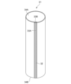
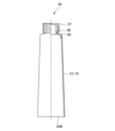
まず図4から図6により、本願発明によるチューブ容器の筒状胴部の積層体10を使用して作成されたチューブ容器30について述べる。
First, referring to FIGS. 4 to 6, a
チューブ容器30は、チューブ容器の筒状胴部の積層体10を含む筒状胴部31と、前記筒状胴部31に対して圧縮成形、射出成形などの方法により合成樹脂を設けることにより作製される肩部35及び口部36とを備えている。また前記チューブ容器30の口部36にキャップ37が装着される。
The
このような構成からなる前記チューブ容器30は、以下のような製造工程を経て得られる。
The
まず、図4に示すように、本願発明によるチューブ容器の筒状胴部の積層体10を用いて、前記チューブ容器の筒状胴部の積層体10の一対の貼り合わせ端部(以下、両端部と呼ぶことがある。)33A、33Bを重ね合わせて、その重ね合せ部分の外面と内面とをヒートシールして貼り合わせて胴貼り部32を形成することにより、筒状胴部31を製造する。次いで、図5に示すように、前記の筒状胴部31を金型(不図示)内に装着し、前記筒状胴部31の一方の開口部(上側)34Aに、例えば、圧縮成形、射出成形などの方法によって、肩部35および口部36を形成する。このようにして筒状胴部31の一方の開口部(上側)34Aに、肩部35および口部36が一体に成形されてチューブ容器30が作製される。そしてチューブ容器30の口部36にキャップ37が装着される。
First, as shown in FIG. 4, a pair of bonded ends (hereinafter, both ends) of the
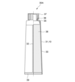
次にチューブ容器30の筒状胴部31の他方の開口部(下側)34Bから、例えば、練り辛子、練りわさび、その他の内容物38が適量分だけ充填される。その後、前記開口部(下側)34Bを溶着して底シール部39を形成して、前記内容物38を充填包装したチューブ容器30を含む包装製品30Aが得られる。
Next, from the other opening (lower side) 34B of the
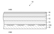
次に図1により、チューブ容器30を作製するチューブ容器の筒状胴部の積層体10について説明する。チューブ容器の筒状胴部の積層体10は、図1に示すように、外面から内面に向かって順に配置されたヒートシール性を有する第一基材層11及び第一シーラント層12と、第二基材層13と、第二シーラント層15とを有する積層体である。
前記第一基材層13の表面に保護層16を設けている。
Next, with reference to FIG. 1, the laminated
A
前記第一基材層11の外面には、コーターによるコート層や、OPニス等のインキなどを用いて保護層16が形成され、第二基材層13の内面には印刷インキを用いて所望の模様を含む内面印刷部13Aが形成されている。なお、第二基材層13の外面に印刷インキを用いて、内面印刷部13Aを設けても良い。
A
前記保護層16よりも内面に絵柄印刷が存在する場合は、前記保護層16は前記絵柄印刷を外部より視認可能となるように、透視可能な層で構成することが望ましい。
When a pattern is printed on the inner surface of the
前記保護層16を形成する第一基材層11の表面には、前記インキなどの密着を確実にするために、適切な凹凸が必要である。前記第一シーラント層12は、予めフィルムで準備されることが多く、その表面は平滑性が強すぎて、その表面にインキなどを塗布する際に、前記インキなどの密着性が劣る場合がある。特に第一シーラント層12に使用するフィルムをインフレーション法にて製膜する場合は、表面が平滑化しやすい傾向がある。
The surface of the
上記のように前記第一シーラント層12と保護層16の密着性が劣る場合には、前記第一シーラント層12の上に、第一基材層11を接合して、前記第一基材層11の表面に適切な凹凸を付与することができる。前記第一基材層11の表面の算術平均高さ(Sa)は、0.1~1.0μmであることが望ましい。0.1μm未満であるとインキの密着性が劣ってしまう虞れがあり、1.0μmを超えるとインキに斑ができて、表面を保護する効果が劣ってしまう虞れがある。また、前記第一基材層11の材質は、コストや加工性から低密度ポリエチレンが望ましい。
なお、算術平均高さ(Sa)が0.08μmであるLLDPEフィルムにフレキソ印刷を施した場合は、インキの密着が悪く、絵柄の一部に印刷剥がれが生じた。
When the adhesion between the
Note that when flexographic printing was performed on an LLDPE film having an arithmetic mean height (Sa) of 0.08 μm, ink adhesion was poor and printing peeled off in part of the pattern.
また、第一シーラント層12と第二基材層13とは、ドライラミネートにより接合され、第一基材層11は第一シーラント層12の表面に押し出しラミネートにより形成されている。さらに第二基材層13と第二シーラント層15とはドライラミネートにより接合されている。
Moreover, the
本明細書において「外面」、「内面」とは、チューブ容器の筒状胴部の積層体10を用いてチューブ容器30を作製した場合における「外面」および「内面」を意味する。また「上側」、「下側」とは、チューブ容器30を、口部36及びキャップ37を上向きにした際に、「上側」とは口部側を、「下側」とは口部の反対側を意味する。
In this specification, "outer surface" and "inner surface" refer to the "outer surface" and "inner surface" when the
次にチューブ容器の筒状胴部の積層体10を構成する各部分の材料について説明する。
Next, the materials of each part constituting the
第一基材層11、第一シーラント層12および第二シーラント層15は例えばポリエチレン(PE)を含んでいてもよい。具体的には、第一基材層11、第一シーラント層12および第二シーラント層15を以下の材料から作製してもよい。
The
第一基材層11、第一シーラント層12および第二シーラント層15はとして、熱によって溶融し相互に融着し得るものであればよく、例えば、低密度ポリエチレン(LDPE)、中密度ポリエチレン(MDPE)、高密度ポリエチレン(HDPE)、直鎖状(線状)低密度ポリエチレン(LLDPE)、ポリプロピレン(PP)、エチレン-酢酸ビニル共重合体、アイオノマー樹脂、エチレン-アクリル酸エチル共重合体、エチレン-アクリル酸共重合体、エチレン-メタクリル酸共重合体、エチレン-プロピレン共重合体、メチルペンテンポリマー、ポリエチレン若しくはポリプロピレン等のポリオレフィン系樹脂をアクリル酸、メタクリル酸、マレイン酸、無水マレイン酸、フマール酸、イタコン酸、その他等の不飽和カルボン酸で変性した酸変性ポリオレフィン系樹脂、ポリ酢酸ビニル系樹脂、ポリエステル系樹脂、ポリスチレン系樹脂、その他等の樹脂の1種ないしそれ以上からなる樹脂を使用することができる。
The
また第二基材層13としては、ポリエチレンテレフタレート(以下、PETと略す。)層を用いることができ、PET層13に印刷を施すことによってPET層13に印刷インキからなる内面印刷部13Aを設けることができる。また、第二基材層13は、チュープ容器の剛性保持を担っている。
Further, as the
また第二基材層13としてPET層を用いる代わりに、ナイロン層を用いてもよく、また少なくとも一方の面に金属蒸着膜を有しガスバリア性をもったPET層を用いてもよく、また少なくとも一方の面に金属蒸着膜を有しガスバリア性をもったナイロン層を用いてもよい。
Furthermore, instead of using a PET layer as the
また、少なくとも一方の面にシリカ蒸着膜を有しガスバリア性をもったPET層を用いてもよく、また少なくとも一方の面にシリカ蒸着膜を有しガスバリア性をもったナイロン層を用いてもよい。 Furthermore, a PET layer having a silica vapor deposited film on at least one surface and having gas barrier properties may be used, or a nylon layer having a silica vapor deposited film on at least one surface and having gas barrier properties may be used. .
また、少なくとも一方の面に酸化アルミ蒸着膜を有しガスバリア性をもったPET層を用いてもよく、また少なくとも一方の面に酸化アルミ蒸着膜を有しガスバリア性をもったナイロン層を用いてもよい。 Further, a PET layer having gas barrier properties and having an aluminum oxide vapor deposited film on at least one surface may be used, or a nylon layer having an aluminum oxide vapor deposited film and gas barrier properties on at least one surface may be used. Good too.
ナイロン層を用いた場合は、PET層よりも機械的強度が優れる場合が多い。
また、各種蒸着膜を備えたフィルムは、基材となるフィルムよりもガスバリア性が優れる。
When a nylon layer is used, the mechanical strength is often superior to that of a PET layer.
Furthermore, films equipped with various vapor-deposited films have better gas barrier properties than the films that serve as the base material.
次にヒートシール性を有する第一基材層11の外面に設けられた保護層16、および第二基材層13の内面に設けられた内面印刷部13Aについて説明する。
Next, the
図7に示すように、保護層16はチューブ容器の筒状胴部の積層体10のうち一対の貼り合わせ端部33A、33B以外の領域に設けられている。このように保護層16を一対の貼り合わせ端部33A、33B以外の領域に設ける理由は、一対の貼り合わせ端部33A、33Bはチューブ容器30を作製する際、互いの外面と内面を重ね合わせて接合する部分となるからである。
As shown in FIG. 7, the
従ってチューブ容器の筒状胴部の積層体10のうち一対の貼り合わせ端部33A、33Bには、保護層16が設けられない。
しかし、前記保護層16が胴貼り形成を阻害しない性質や、熱シールの際に破壊されない性質などを有する場合は、前記一対の貼り合わせ端部33A、33Bのいずれか一方又は両方に保護層16を設けてもよい。
上記の一対の貼り合わせ端部33A、33B以外の領域であっても、必要に応じて前記保護層16を部分的に削除や形成してもよい。
Therefore, the
However, if the
If necessary, the
他方、第二基材層13の内面に設けられた内面印刷部13Aは、平滑でかつ透明性が優れる第二基材層13に印刷されることから、美粧性に秀でた印刷をすることが可能である。
On the other hand, since the inner
なお、図7において、切断線Lにより切断される前の連続する複数のチューブ容器の筒状胴部の積層体の原反10Aが示されている。
In addition, in FIG. 7, the
次にチューブ容器の筒状胴部の積層体10の製造方法について図1により説明する。
Next, a method for manufacturing the
まず第二基材層13の内面に印刷が施されて、このようにして第二基材層13の内面に印刷インキからなる内面印刷部13Aが設けられる。
First, printing is performed on the inner surface of the second
次に第二基材層13の内面にドライラミネート(DL)により第二シーラント層15が接合される。
Next, the
次に第二基材層13の外面に第一シーラント層12がドライラミネートにより接合される。
Next, the
次に第一シーラント層12の外面に、第一基材層11が押し出しラミネートにより形成される。
Next, the
次に、第一基材層11の外面には保護層16が印刷により施され、このようにして第一基材層11の外面に印刷からなる保護層16が設けられる。
上記のようにして、チューブ容器の筒状胴部の積層体10が得られる。
Next, the
In the manner described above, the
このようにして得られたチューブ容器の筒状胴部の積層体10は円筒状に巻かれ、上述のようにその両端部33A、33Bが重ね合わされて、両端部33A、33Bにおいてチューブ容器の筒状胴部の積層体10の外面と内面がヒートシールされて、胴貼り部32が形成され、筒状胴部31が作製される。
この場合、チューブ容器の筒状胴部の積層体10の外面側に設けられた第一基材層11及び第一シーラント層12と、内面側に設けられた第二シーラント層15とが溶融して接合され、筒状胴部31が得られる。
The thus obtained
In this case, the first
なお、上記では胴貼り部32は、重ね合わせにより形成されるが、両端部33A、33Bのそれぞれの端面を、突き合わせて接合してもよい。さらに、上記にて付き合わせて接合した接合線を、筒状胴部31の内面または外面にフィルムを貼付して保護してもよい。
また、内側となる端部33Bには、端面保護のための加工をしてもよい。例えばテープ貼りによる保護や、前記端部33Bを容器の外側方向に折り曲げる加工(ヘミング加工)などがある。
In addition, although the trunk|
Further, the
次に、前記筒状胴部31の開放部(上側)34Aが金型(不図示)内に挿着され、前記筒状胴部31に圧縮成形、射出成形などの方法を用いて、前記筒状胴部31の開放部(上側)34Aに肩部35と口部36が形成されて、チューブ容器30が得られる(図4および図5参照)。
Next, the open part (upper side) 34A of the
次に、上記のようにして製造されたチューブ容器30の口部36にキャップ37が装着され、キャップ37が装着されたチューブ容器30は複数まとめてダンボール箱内に収納される。その後、キャップ37が装着された複数のチューブ容器30は、ダンボール箱毎搬送される。
Next, a
以上のように、本願発明の第一の実施形態によれば、保護層16は一対の貼り合わせ端部33A、33B以外の領域に設けられ、前記保護層16は優れた耐傷性を有するため、耐傷性に優れたチューブ容器30を製造することができる。
As described above, according to the first embodiment of the present invention, the
<本願発明の第二の実施形態>
次に図2により本願発明の第二の実施形態について説明する。
<Second embodiment of the present invention>
Next, a second embodiment of the present invention will be described with reference to FIG.
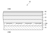
図2に示す第二の実施形態は、チューブ容器の筒状胴部の積層体10の第二基材層13にドライラミネートによりガスバリア層14を貼り合わせ、このガスバリア層14に第二シーラント層15をドライラミネートにより接合したものである。
図2に示す第二の実施形態において、上記以外の構成は図1、図4から図6に示す第一の実施形態と同様であり、第一の実施形態と同一部分には同一符号を付して、詳細な説明は省略する。
In the second embodiment shown in FIG. 2, a
In the second embodiment shown in FIG. 2, the configuration other than the above is the same as the first embodiment shown in FIGS. 1 and 4 to 6, and the same parts as in the first embodiment are given the same reference numerals. Therefore, detailed explanation will be omitted.
第二の実施形態において、チューブ容器の筒状胴部の積層体10は第二基材層13と第二シーラント層15との間に配置されたガスバリア層14を更に有し、このガスバリア層14としては、金属箔、または基材フィルムとこの基材フィルム上に蒸着された蒸着膜とを有するフィルム、素材自体にガスバリア性を有するフィルムなどを用いることができる。
In the second embodiment, the
具体的には、ガスバリア層14として用いられる金属箔には、例えば、アルミ箔があげられる。アルミ箔は、ガスバリア性能が優れ、遮光性を有し、コストパフォーマンスが優れる材料である。
Specifically, the metal foil used as the
また、蒸着膜が設けられる基材フィルムとしては、ポリエチレン系樹脂、ポリプロピレン系樹脂、環状ポリオレフィン系樹脂、フッ素系樹脂、ポリスチレン系樹脂、アクリロニトリル-スチレン共重合体(AS樹脂)、アクリロニトリル‐ブタジエン‐スチレン共重合体(ABS樹脂)、ポリ塩化ビニル系樹脂、フッ素系樹脂、ポリ(メタ)アクリル系樹脂、ポリカーボネート系樹脂、ポリエチレンテレフタレート(PET)、ポリエチレンナフタレート等のポリエステル系樹脂、各種のナイロン等のポリアミド系樹脂、ポリイミド系樹脂、ポリアミドイミド系樹脂、ポリアリルフタレート系樹脂、シリコーン系樹脂、ポリスルホン系樹脂、ポリフェニレンスルフィド系樹脂、ポリエーテルスルホン系樹脂、ポリウレタン系樹脂、アセタール系樹脂、セルロース系樹脂、その他等の各種の樹脂のフィルムないしシートを使用することができる。 In addition, the base film on which the vapor deposited film is provided includes polyethylene resin, polypropylene resin, cyclic polyolefin resin, fluorine resin, polystyrene resin, acrylonitrile-styrene copolymer (AS resin), acrylonitrile-butadiene-styrene. Copolymers (ABS resins), polyvinyl chloride resins, fluorine resins, poly(meth)acrylic resins, polycarbonate resins, polyester resins such as polyethylene terephthalate (PET) and polyethylene naphthalate, various types of nylon, etc. Polyamide resin, polyimide resin, polyamideimide resin, polyallyl phthalate resin, silicone resin, polysulfone resin, polyphenylene sulfide resin, polyether sulfone resin, polyurethane resin, acetal resin, cellulose resin, Films or sheets of various other resins can also be used.
なお、本願発明においては、蒸着膜が設けられる基材フィルムとして、特に、PETは、性能とコストのバランスが良く、使用することが好ましいものである。
また、本願発明においては、蒸着膜が設けられる基材フィルムとして、特に機械的な強度が求められる状況では、ナイロンを使用することが好ましいものである。
In addition, in the present invention, it is particularly preferable to use PET as the base film on which the vapor deposited film is provided, since it has a good balance between performance and cost.
Further, in the present invention, it is preferable to use nylon as the base film on which the vapor deposited film is provided, especially in situations where mechanical strength is required.
また、基材フィルム上に蒸着される蒸着膜としては、シリカ蒸着膜を用いることができ、ガスバリア層14として基材フィルムとシリカ蒸着膜とを含むシリカ蒸着PETを用いることができる。
Moreover, a silica vapor-deposited film can be used as the vapor-deposited film deposited on the base film, and a silica-deposited PET containing a base film and a silica-deposited film can be used as the
また、基材フィルム上に蒸着される蒸着膜としては、アルミ蒸着膜を用いることができ、ガスバリア層14として基材フィルムとアルミ蒸着膜とを含むアルミ蒸着PETを用いることができる。
Moreover, an aluminum vapor-deposited film can be used as the vapor-deposited film deposited on the base film, and aluminum-deposited PET containing the base film and the aluminum vapor-deposited film can be used as the
また、基材フィルム上に蒸着される蒸着膜としては、酸化アルミ(アルミナ)蒸着膜を用いることができ、ガスバリア層14として基材フィルムと酸化アルミ(アルミナ)蒸着膜とを含むアルミナPETを用いることができる。
Further, as the vapor deposited film deposited on the base film, an aluminum oxide (alumina) vapor deposited film can be used, and an alumina PET containing the base film and an aluminum oxide (alumina) vapor deposited film is used as the
素材自体にガスバリア性を有するフィルムとしては、エチレン・ ビニルアルコール共重合樹脂(EVOH)、ナイロンMXD6、ポリアクリロニトリル(PAN)、ポリ塩化ビニリデン(PVDC)などがあり、それらのフィルムをガスバリア層14とすることができる。
Examples of films that have gas barrier properties themselves include ethylene-vinyl alcohol copolymer resin (EVOH), nylon MXD6, polyacrylonitrile (PAN), and polyvinylidene chloride (PVDC), and these films are used as the
なお、上記第一および第二の実施形態において、第一基材層11と第二基材層13との間に、第一シーラント層12を設けた例を示したが、第一基材層11が充分なヒートシール機能をもつ場合、第一シーラント層12は必ずしも設ける必要はない。
その他、記載のない構成要素は、第一の実施形態と同様である。
In addition, in the first and second embodiments, an example was shown in which the
Other components not described are the same as those in the first embodiment.
なお、第二の実施例においては、印刷のある第二基材層13と、ガスバリア層14を別体としたが、前記ガスバリア層14に印刷適性がある場合には、前記ガスバリア層14に印刷を施し、前記第二基材層13を削減してもよい。このような場合、前記第二基材層13を削減することによるコストダウンが可能である。
In the second embodiment, the
上記に記載の印刷適性について説明する。前記ガスバリア層14の内面に裏刷り印刷を施す場合は、前記ガスバリア層14の透視性が要求される。また印刷工程では、前記ガスバリア層14に張力がかかることから、所定の強度を有し、かつ伸びが少ないことが要求される。
The printability described above will be explained. When reverse printing is performed on the inner surface of the
逆に、印刷のある第二基材層13とガスバリア層14を別体にするメリットについて説明する。特に高いガスバリア性を要求される用途では、印刷工程にて蒸着層が損傷される虞れがあるため、ガスバリア層14には印刷を施さない方が望ましい。そのため、第二基材層13とガスバリア層14を別体にすることが望ましい。
On the contrary, the merits of making the printed
<本願発明の第三の実施形態>
次に図3により本願発明の第三の実施形態について説明する。
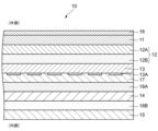
意匠性向上のために、印刷のある第二基材層13の内面側に乳白色のポリエチレンからなる意匠性向上層17を設けている。意匠性向上層17は、前記第二基材層13に直接接触して接合されていてもよく、また、前記第二基材層13と光の透過性を有する層(不図示)を介して接合されていてもよい。
<Third embodiment of the claimed invention>
Next, a third embodiment of the present invention will be described with reference to FIG.
In order to improve the design, a
また、ガスバリア層14と、前記ガスバリア層14の表裏面に接触する各層との接合強度を向上させるため、前記ガスバリア層14表裏面に接着層18A、18Bを設けている。特にガスバリア層14にアルミ箔を用いる場合は、前記アルミ箔の接合界面の接合強度を向上させるために、接着層を設けることが望ましい。
Further, in order to improve the bonding strength between the
ガスバリア性を担保する層としては、上記に記載した各種のフィルムなどを例示として、チューブ容器への要求性能、コストなどにより、適宜選定される。
その他、記載のない構成要素は、第一の実施形態、第二の実施形態と同様である。
The layer ensuring gas barrier properties may be appropriately selected depending on the performance required for the tube container, cost, etc., with examples of the various films described above.
Other components not described are the same as those in the first embodiment and the second embodiment.
次に本願発明の具体的実施例について説明する。 Next, specific embodiments of the present invention will be described.
(実施例1)
実施例1は、上記の第一の実施形態に対応するものである。
チューブ容器の筒状胴部の積層体10として、以下のような層構成をもつ積層体10を準備した。
(Example 1)
Example 1 corresponds to the first embodiment described above.
A laminate 10 having the following layer structure was prepared as the
ニス塗布層16/LDPE層11(20μm)/LLDPE層12(100μm)/PET層13(12μm)/内面印刷部13A/LLDPE層15(210μm)
ここで、ニス塗布層16は、LDPE層11の表面にフレキソ印刷にて塗布される。LDPE層11は低密度ポリエチレンからなり、第一基材層11を構成する。またLLDPE層12は直鎖状低密度ポリエチレンからなり、第一シーラント層12を構成する。またPET層13はポリエチレンテレフタレート(PET)からなり、第二基材層13を構成する。さらにLLDPE層15は直鎖状低密度ポリエチレンからなり、第二シーラント層15を構成する。
なお、ニス塗布層16はグラビア印刷や、コーターなどで塗布することもできる。
Here, the
Note that the
実施例1の積層体10の製造方法を説明する。
A method for manufacturing the
前記積層体10を製造するにあたり、まずは、PET層13となるPETフィルム(12μm)の内面に、PETフィルムの外面側から見て正規の絵柄となるように、裏刷り印刷としてグラビア印刷機にて印刷した。
In manufacturing the
次に、上記の手順で印刷したPET層13となるPETフィルムの外面に、第一シーラント層12となるLLDPEフィルム12(100μm)を、また内面に第二シーラント層15となるLLDPEフィルム15(210μm)をドライラミネート機にて、ドライラミネートした。
Next, the LLDPE film 12 (100 μm) that will become the
次に、上記の手順で積層した積層体の外面側のLLDPE層12の外面に、押し出し機を用いて、溶融したLDPEを膜状に押し出し加工して、第一基材層11となるLDPE層11(20μm)を形成した。溶融した膜状の前記LDPE層11を冷却し、固化する冷却ロールの表面には、適切な凹凸形状を備えているため、前記LDPE層11の表面は、印刷適性のある凹凸形状を備える。
Next, an extruder is used to extrude melted LDPE into a film on the outer surface of the
次に、上記の手順で積層した積層体の外面側のLDPE層11の外面に、フレキソ印刷機を用いてインキを塗布して、ニス塗布層16を形成した。インキは紫外線照射硬化型ニス(OPニス 組成 感光性モノマー75~85質量%、光重合開始剤15~25質量%、補助剤1~10質量%、2,6-ジ-t-ブチル-4-メチルフェノール1質量%未満)を用いており、フレキソ印刷機の排出側に設けられた紫外線照射部を、紫外線照射硬化型ニスからなる保護層16を備えた前記積層体が通過すると、前記ニスが硬化して、前記保護層16の表面の硬度が大きくなり、耐傷性が向上して、さらに摩擦係数が低減する。
Next, a
上記の各印刷工程における印刷適性の向上や、インキの密着性の向上などのために、また各ラミネート工程におけるラミネート強度の向上などのために、各層の表面に、コロナ処理などの表面処理や、アンカーコート剤の塗布を適宜実施してもよい。 In order to improve printability and ink adhesion in each of the above printing processes, and to improve lamination strength in each lamination process, the surface of each layer is subjected to surface treatments such as corona treatment, etc. An anchor coating agent may be applied as appropriate.
実施例1におけるチューブ容器30について、一対の貼り合わせ端部33Aの内側と33Bの外側の接合強度、及びチューブの筒状胴部の積層体10と肩部35との間の接合強度を測定した。上記の2つの接合強度とも充分な強度があり、チューブ容器として問題がない水準であった。
Regarding the
(実施例2)
実施例2は上記の第二の実施形態に対応するものである。
チューブ容器の筒状胴部の積層体10として、以下のような層構成をもつ積層体を準備した。
(Example 2)
Example 2 corresponds to the second embodiment described above.
A laminate having the following layer structure was prepared as the
ニス塗布層16/LDPE層11(20μm)/LLDPE層12(100μm)/PET層13(12μm)/内面印刷部13A/(蒸着面)VM-PET層14(12μm)/LLDPE層15(210μm)。
ここで、ニス塗布層16は、LDPE層11の表面にフレキソ印刷にて塗布される。LDPE層11は低密度ポリエチレンからなり、第一基材層11を構成する。またLLDPE層12は直鎖状低密度ポリエチレンからなり、第一シーラント層12を構成する。またPET層13はポリエチレンテレフタレート(PET)からなり、第二基材層13を構成する。前記第二基材層13の内側にグラビア印刷による内面印刷部13Aが形成される。またVM-PET層14はアルミ蒸着ポリエチレンテレフタレート層からなり、ガスバリア層14を構成する。なお、前記VM-PET層14の蒸着面は外側である。蒸着面を外側にすることにより、蒸着面を内面にする場合に比較して、内容物による蒸着面へのアタックが緩和されて、蒸着膜の劣化が少なくなる場合がある。さらにLLDPE層15は直鎖状低密度ポリエチレンからなり、第二シーラント層15を構成する。
Here, the
実施例2の積層体10の製造方法を説明する。
前記積層体10を製造するにあたり、まずは、PET層13となるPETフィルム(12μm)の内面に、PETフィルムの外面側から見て正規の絵柄となるように、裏刷り印刷としてグラビア印刷機にて印刷した。
A method for manufacturing the
In manufacturing the
次に、上記の手順で印刷したPETフィルムの内面に、順次、ガスバリア層14となるVM-PET層14(12μm)を、さらに前記ガスバリア層14の内面に第二シーラント層15となるLLDPEフィルム15(210μm)をドライラミネート機にて、ドライラミネート(DL)する。前記VM-PET層14の蒸着面は外側である。
Next, a VM-PET layer 14 (12 μm), which will become the
次に、上記の手順で積層した積層体のPET層13となるPETフィルムの外面に、第一シーラント層12となるLLDPEフィルム12(100μm)を、ドライラミネート機にて、ドライラミネートする。
Next, an LLDPE film 12 (100 μm), which will become the
次に、上記の手順で積層した積層体の外面側のLLDPEフィルム12の外面に、押し出し機を用いて、溶融したLDPEを膜状に押し出し加工して、第一基材層11となるLDPE層11(20μm)を形成する。溶融した膜状の前記LDPE層11を冷却し、固化する冷却ロールの表面には、適切な凹凸形状を備えているため、前記LDPE層11の表面は、印刷適性のある凹凸形状を備える。
Next, an extruder is used to extrude melted LDPE into a film on the outer surface of the
次に、上記の手順で積層した積層体の外面側のLDPEフィルム11の外面に、フレキソ印刷機を用いてインキを塗布して、ニス塗布層16を形成する。インキは紫外線照射硬化型ニス(実施例1と同じ)を用いており、フレキソ印刷機の排出側に設けられた紫外線照射部を、紫外線照射硬化型ニスによる保護層16を備えた前記積層体が通過すると前記ニスが硬化して、前記保護層16の表面の硬度が大きくなり、耐傷性が向上して、さらに摩擦係数が低減する。
Next, ink is applied to the outer surface of the
実施例2におけるチューブ容器30について、一対の貼り合わせ端部である33Aの内側と33Bの外側の接合強度、及びチューブの筒状胴部の積層体10と肩部35との間の接合強度を測定した。上記の2つの接合強度とも充分な強度があり、チューブ容器として問題がない水準であった。
Regarding the
(実施例3)
実施例3は上記の第三の実施形態に対応するものである。
チューブ容器の筒状胴部の積層体10として、以下のような層構成をもつ積層体を準備した。
(Example 3)
Example 3 corresponds to the third embodiment described above.
A laminate having the following layer structure was prepared as the
ニス塗布層16/LDPE層11(30μm)/LLDPE12A(60μm)/LDPE層12B(20μm)/PET層13(12μm)/内面印刷部13A(アンカーコート)/乳白色のLLDPE層17(100μm)/EMAA層18A(20μm)/アルミ箔14(10μm)/EMAA層18B(30μm)/LLDPE15(100μm)。
ここで、ニス塗布層16は、LDPE層11の表面にフレキソ印刷にて塗布される。LDPE層11は低密度ポリエチレンからなり、第一基材層11を構成する。またLLDPE層12は直鎖状低密度ポリエチレンからなり、第一シーラント層12を構成する。またPET層13はポリエチレンテレフタレート(PET)からなり、第二基材層13を構成する。前記第二基材層13の内側にグラビア印刷による内面印刷部13Aが形成される。また乳白色のLLDPE層17は、乳白色に着色されたまた直鎖状低密度ポリエチレンからなり、意匠性向上層17を構成する。EMAA層18Aはエチレン・メタクリル酸共重合物からなり、接着層18Aを構成する。またアルミ箔14はガスバリア層14を構成する。またEMAA層18Bはエチレン・メタクリル酸共重合物からなり、接着層18Bを構成する。さらにLLDPE15は直鎖状低密度ポリエチレンからなり、第二シーラント層15を構成する。
Here, the
実施例3の積層体10の製造方法を説明する。
A method for manufacturing the
前記積層体10を製造するにあたり、まずは、PET層13となるPETフィルム(12μm)の内面に、PETフィルムの外面側から見て正規の絵柄となるように、裏刷り印刷としてグラビア印刷機にて印刷した。
In manufacturing the
次に、上記の手順で印刷したPET層13となるPETフィルムの内面に、乳白色のLLDPE層17となる予め準備されたフィルムをドライラミネート機でドライラミネートする。
Next, a previously prepared film that will become the milky
次に、上記の手順で積層した積層体の前記LLDPE層17の内面に、押し出し機を用いて溶融したEMAA層18Aを膜状に押し出して、接着層18Aとなる前記EMAA層18Aが溶融している状態で、前記ガスバリア層14となるアルミ箔14を接合させた後、前記EMAA層18Aが冷却されて、前記アルミ箔14と凝固・接着する。
Next, an extruder is used to extrude the melted
また上記の工程に次いで、前記アルミ箔14の内面に、溶融したEMAA層18Bを膜状に押し出して、接着層18Bとなる前記EMAA層18Bが溶融している状態で、前記LLDPE層15となる予め準備されたLLDPEフィルムを接合させた後、前記EMAA層18Bが冷却されて、前記LLDPE層15と凝固・接着する。なお、EMAAはLDPEよりも金属への接着力が強く、アルミ箔のラミネート強度の向上に有効である。
Further, following the above steps, the melted
次に、上記の手順で積層した積層体のPETフィルムの外面に、ポリウレタン系アンカーコート剤でアンカーコートを施した後、押し出し機を用いて溶融したLDPE層12Bを膜状に押し出して、接着層12Bとなる前記LDPE層12Bが溶融している状態で、前記LDPE層12Bの外面側にLLDPE層12Aとなる予め準備されたフィルムを接合させる。その後、前記LDPE層12Bが冷却されて、前記LLDPE層12Aと凝固・接着する。
Next, the outer surface of the PET film of the laminate laminated in the above procedure is coated with a polyurethane anchor coating agent, and then the
また上記の工程に次いで、前記LLDPE層12Aの外面に、溶融したLDPE層11を膜状に押し出し加工して、その後、冷却されて、第一基材層11となるLDPE層11(20μm)を形成する。溶融した膜状の前記LDPE層11を冷却し、固化する冷却ロールの表面には、適切な凹凸形状を備えているため、前記LDPE層11の表面は、印刷適性のある凹凸形状を備える。
Further, following the above steps, the
次に、上記の手順で積層した積層体の外面側のLDPE層11の外面に、フレキソ印刷機を用いてインキを塗布して、ニス塗布層16を形成する。インキは紫外線照射硬化型ニス(実施例1と同じ)を用いており、フレキソ印刷機の排出側に設けられた紫外線照射部を、紫外線照射硬化型ニスによる保護層16を備えた前記積層体が通過すると前記ニスが硬化して、前記保護層16の表面の硬度が大きくなり、耐傷性が向上して、さらに摩擦係数が低減する。
Next, a
実施例3におけるチューブ容器30について、一対の貼り合わせ端部である33Aの内側と33Bの外側の接合強度、及びチューブの筒状胴部の積層体10と肩部35との間の接合強度を測定した。上記の2つの接合強度とも充分な強度があり、チューブ容器として問題がない水準であった。
Regarding the
(比較例)
比較例は、ニス塗布層16からなる保護層16を有しない点が異なるのみであり、他は実施例3と同様の構成、製造方法で製造されたチューブ容器である。
(Comparative example)
The comparative example is a tube container manufactured using the same configuration and manufacturing method as Example 3, except that it does not have the
(各種実施例と比較例の比較・評価)
各種実施例のサンプルと比較例のサンプルについて、摩擦係数測定試験、摩擦試験(耐傷性試験)、輸送試験を実施した。
(Comparison and evaluation of various examples and comparative examples)
A friction coefficient measurement test, a friction test (scratch resistance test), and a transportation test were conducted on samples of various examples and samples of comparative examples.
(表面の摩擦係数測定)
各種実施例と比較例の表面の摩擦係数を測定した。その結果を表1に示す。
測定機器は、株式会社東洋精機製作所製TR-2を使用し、JIS K-7125に準じて、静止摩擦係数と動摩擦係数の測定を行った。試験回数はn=3、試験速度は100mm/minであった。
(Surface friction coefficient measurement)
The friction coefficients of the surfaces of various Examples and Comparative Examples were measured. The results are shown in Table 1.
The measuring device used was TR-2 manufactured by Toyo Seiki Seisakusho Co., Ltd., and the static friction coefficient and dynamic friction coefficient were measured in accordance with JIS K-7125. The number of tests was n=3, and the test speed was 100 mm/min.
測定結果を表1に示す。
表1における摩擦対象面の項目に記載のチューブ容器の筒状胴部の積層体の表面とは、同じ材質の組み合せで摩擦係数の測定を行っており、チューブ容器を輸送する際のチューブ同士の擦れを想定している。
摩擦対象面の項目に記載の金属面とは、チューブ容器の充填・包装作業時の搬送工程において、金属製部品との接触を想定している。今回、摩擦測定に使用した金属面は、ステンレスであり、平面で表面が平滑性のあるミラーの性状をしている。
The measurement results are shown in Table 1.
The friction coefficient of the surface of the laminate of the cylindrical body of the tube container described in the item of surface subject to friction in Table 1 is measured using the same combination of materials, and the friction coefficient between the tubes when transporting the tube container is measured. Expect some friction.
The metal surface described in the item of surface subject to friction is assumed to come into contact with metal parts during the transportation process during filling and packaging of tube containers. The metal surface used for friction measurements this time was stainless steel, and has the properties of a mirror with a flat, smooth surface.

表1より、以下のことが分かる。
摩擦対象面がチューブ容器の筒状胴部の積層体の表面において、比較例よりも各種実施例の方が、静止摩擦係数、動摩擦係数とも小さくなっており、各種実施例の方が、チューブ容器表面に生じる摩擦力が小さいため、表面の損傷が少なくなる。このことにより、チューブ容器の輸送時に、各種実施例の方が、表面に傷を生じにくくなる。
From Table 1, the following can be seen.
When the friction target surface is the surface of the laminate of the cylindrical body of the tube container, both the static friction coefficient and the kinetic friction coefficient are smaller in the various examples than in the comparative example. Since the frictional force generated on the surface is small, there is less damage to the surface. This makes the various embodiments less likely to cause scratches on the surface during transportation of the tube container.
摩擦対象面が金属面の場合において、比較例よりも各種実施例の方が、静止摩擦係数、動摩擦係数とも小さくなっており、各種実施例の方が、チューブ容器表面に生じる摩擦力が小さいため、表面の損傷が少なくなる。このことにより、チューブ容器の充填・包装作業時の搬送工程において、金属製部品との接触をした場合に、各種実施例の方が、表面に傷を生じにくくなる。 When the surface to be rubbed is a metal surface, both the static friction coefficient and the kinetic friction coefficient are smaller in the various examples than in the comparative example, and the frictional force generated on the tube container surface is smaller in the various examples. , less damage to the surface. As a result, the various embodiments are less likely to cause scratches on the surface when they come into contact with metal parts during the transport process during filling and packaging of tube containers.
また、トップにプレートがあるタイプの搬送チェーンにおいて、そのプレートの上にチューブ容器のキャップの天面を下向きに置かれ、キャップの天面とコンベアのプレートの摩擦力だけで搬送されて、かつチューブ容器の筒状胴部が、搬送コンベアに付設される金属製のガイドで規制されつつ搬送される場合がある。筒状胴部の摩擦係数が小さいチューブ容器において、前記ガイドによるチューブ容器の筒状胴部への摩擦力が小さくなるため、チューブ容器のライン上での引っ掛かりや転倒が少なくなり、その結果、生産阻害が少なくなる。 In addition, in a type of conveyor chain that has a plate on the top, the cap of a tube container is placed on the plate with the top surface facing downward, and the tube container is transported only by the frictional force between the top surface of the cap and the conveyor plate. The cylindrical body of the container may be conveyed while being regulated by a metal guide attached to the conveyor. In a tube container whose cylindrical body has a small coefficient of friction, the frictional force exerted by the guide on the cylindrical body of the tube container is small, which reduces the chance of the tube container getting caught or falling over on the line, resulting in a reduction in production. Less inhibition.
(表面の耐傷性の評価)
表面の耐傷性の評価を、学振式摩擦試験(JIS L-0849)で評価した。測定機器は、スガ試験機株式会社製 FR-2である。
(Evaluation of surface scratch resistance)
The scratch resistance of the surface was evaluated using a Gakushin friction test (JIS L-0849). The measuring device was FR-2 manufactured by Suga Test Instruments Co., Ltd.
前記積層体同士の摩擦試験を行う際は、下側の試験片台に、短冊状(幅30mm)のチューブ容器の筒状胴部の積層体を固定し、上側の摩擦子に、同じ材質のチューブ容器の筒状胴部の積層体を短冊状(幅30mm)にして取り付けた。
前記積層体と金属板との摩擦試験を行う際は、上側の摩擦子に金属板を取り付けて、前記摩擦子を摺動させた。今回、学振式摩擦試験に使用した金属板は、ステンレスであり、表面が平滑性のあるミラーの性状をしている。
また、錘は200gのものを使用した。
When performing the friction test between the laminated bodies, the laminated body of the cylindrical body of a rectangular tube container (
When performing a friction test between the laminate and a metal plate, a metal plate was attached to the upper friction element and the friction element was slid. The metal plate used in the Gakushin-style friction test this time is stainless steel, and has a smooth mirror-like surface.
Further, a weight of 200 g was used.
上記の学振式摩擦試験を100回および300回繰り返し、その結果、前記積層体の表面に生じた傷の本数を目視にて数えた。1つのサンプル当たりの傷の本数が20本以上のものは試験の結果を×(不良)とし、傷の本数が10本以上20本未満のものは結果を△(やや不良)とし、傷の本数が10本未満のものは試験の結果を○(良好)とした。 The above Gakushin friction test was repeated 100 and 300 times, and the number of scratches produced on the surface of the laminate was visually counted. If the number of scratches per sample is 20 or more, the test result will be marked as × (poor), and if the number of scratches is 10 or more but less than 20, the result will be marked as △ (slightly poor). If there were less than 10 lines, the test result was rated ○ (good).
摩擦係数測定の時と同様、摩擦対象面の項目に記載のチューブ容器の筒状胴部の積層体の表面とは、同じ材質の組み合せで摩擦係数の測定を行っており、チューブ容器を輸送する際のチューブ同士の擦れを想定している。
摩擦対象面における金属面とは、チューブ容器の充填・包装作業時の搬送工程において、ガイド部品などの金属製部品との接触を想定している。
As with the friction coefficient measurement, the surface of the laminate of the cylindrical body of the tube container described in the item of friction target surface is the same combination of materials for the friction coefficient measurement, and the surface of the laminate of the tube container's cylindrical body described in the item of surface to be rubbed is measured for the friction coefficient. It is assumed that the tubes will rub against each other during the test.
The metal surface of the surface subject to friction is assumed to come into contact with metal parts such as guide parts during the transportation process during filling and packaging of tube containers.

表2より、以下のことが分かる。
チューブ容器の筒状胴部の積層体の表面同士の摩擦試験では、比較例において摩擦回数100回では△(やや不良)、摩擦回数300回では×(不良)であった。また、各種実施例において摩擦回数100回では○(良好)、摩擦回数300回では○(良好)であった。
このことから、チュープ容器同士の擦れにおいて、各種実施例は傷がつきにくく、比較例よりも耐傷性が向上していることが分かる。
From Table 2, the following can be seen.
In the friction test between the surfaces of the laminated body of the cylindrical body of the tube container, in the comparative example, the results were △ (slightly poor) after 100 frictions, and × (poor) after 300 frictions. In addition, in various examples, the results were ○ (good) when the number of frictions was 100 times, and ○ (good) when the number of frictions was 300 times.
From this, it can be seen that the various Examples are less likely to be scratched when the tube containers rub against each other, and have improved scratch resistance than the Comparative Examples.
また、チューブ容器の筒状胴部の積層体の表面と金属面との摩擦試験では、比較例において摩擦回数100回では○(良好)、摩擦回数300回では△(やや不良)であった。また、実施例3において摩擦回数100回では○(良好)、摩擦回数300回では○(良好)であった。
このことから、チューブ容器の表面と金属製部品の擦れにおいて、各種実施例は傷がつきにくく、比較例よりも耐傷性が向上していることが分かる。
In addition, in the friction test between the surface of the laminate of the cylindrical body of the tube container and the metal surface, in the comparative example, the results were ○ (good) when the number of frictions was 100 times, and △ (slightly poor) when the number of frictions was 300 times. Further, in Example 3, the result was ○ (good) when the number of frictions was 100 times, and ○ (good) when the number of frictions was 300 times.
From this, it can be seen that the various examples are less likely to be scratched when the surface of the tube container rubs against the metal parts, and the scratch resistance is improved compared to the comparative example.
(実輸送試験による耐傷性の評価)
実施例3と比較例のサンプルを、実輸送試験を行った。準備したサンプルに水を充填して包装製品とした状態で、段ボール箱に各々10本詰めて、東京都新宿区から京都府京田辺市の間を、宅配便(陸路)を利用して、往復輸送した。片道約475kmであり、往復で約950kmであった。
(Evaluation of scratch resistance through actual transportation test)
The samples of Example 3 and Comparative Example were subjected to an actual transportation test. The prepared samples were filled with water and made into packaged products, packed in 10 cardboard boxes each, and transported round trip between Shinjuku Ward, Tokyo and Kyotanabe City, Kyoto Prefecture using courier service (land route). did. It was about 475km one way and about 950km round trip.
到着後に、段ボール箱を開梱して、チューブ容器を目視にて観察した。前記チューブ容器の筒状胴部の表面に生じた傷の本数を数えた。1本のチューブ容器当たりの傷の本数が20本以上のものは試験の結果を×(不良)とし、傷の本数が10本以上20本未満のものは結果を△(やや不良)とし、傷の本数が10本未満のものは試験の結果を○(良好)とした。 Upon arrival, the cardboard box was unpacked and the tube container was visually observed. The number of scratches produced on the surface of the cylindrical body of the tube container was counted. If the number of scratches per tube container is 20 or more, the test result will be marked as × (poor), and if the number of scratches is 10 or more but less than 20, the result will be marked as △ (slightly poor). If the number of the samples was less than 10, the test result was rated as ○ (good).
その結果を表3に示す。
各々10本のチューブ容器の傷つき方は、同様であり差がなかった。
The results are shown in Table 3.
The damage to each of the 10 tube containers was similar and there was no difference.

表3より以下のことが分かる。
比較例のサンプルでは、傷が多数発生しており、外観不良であった。実施例3のサンプルでは、傷が10本未満であり、良好であった。
このことから、実輸送試験において、実施例3のチューブ容器は、耐傷性に優れており、美粧性を保つことができることが分かった。
The following can be seen from Table 3.
The sample of the comparative example had many scratches and had a poor appearance. The sample of Example 3 had less than 10 scratches, which was good.
From this, in the actual transportation test, it was found that the tube container of Example 3 had excellent scratch resistance and was able to maintain its cosmetic appearance.
本願発明によれば、チューブ容器の筒状胴部の積層体の表面の摩擦係数が低いチューブ容器を提供できることから、チューブ容器の包装製品の充填・包装ラインにおいて、チューブ容器のライン上での引っ掛かりや転倒を防止できて、チューブ容器の包装製品の充填・包装ラインが安定稼働できて、品質向上及び生産コストの低減に寄与できる。また、チューブ容器の外面が傷つきにくいことから、店頭において美粧性がある製品を展示することができて、購買意欲を喚起することができる。 According to the present invention, it is possible to provide a tube container in which the surface of the laminate of the cylindrical body of the tube container has a low coefficient of friction. It is possible to prevent tube containers from falling over and overturning, and the filling and packaging line for tube container packaging products can operate stably, contributing to quality improvement and production cost reduction. Furthermore, since the outer surface of the tube container is not easily damaged, it is possible to display products with cosmetic properties at stores, thereby stimulating the desire to purchase them.
10 チューブ容器の筒状胴部の積層体
10A チューブ容器の筒状胴部の積層体の原反
11 第一基材層
12 第一シーラント層
12A 第一シーラント層の一部の層
12B 第一シーラント層の一部の層(兼接着層)
13 第二基材層
13A 内面印刷部
14 ガスバリア層
15 第二シーラント層
16 保護層
17 意匠性向上層
18A 接着層
18B 接着層
30 チューブ容器
30A チューブ容器の包装製品
31 筒状胴部
32 胴貼り部
33A 胴貼りの際に外側となる貼り合わせ端部
33B 胴貼りの際に内側となる貼り合わせ端部
34A 開口部(上側)
34B 開口部(下側)
35 肩部
36 口部
37 キャップ
38 内容物
39 底シール部
L 切断線
10 Laminated body of the cylindrical body of the
13 Second
34B opening (lower side)
35
L cutting line
Claims (6)
前記胴部の積層体は、外面から内面に向かって、少なくとも、第一基材層、第一シーラント層、第二基材層、第二シーラント層がこの順に積層され、
前記第一基材層が低密度ポリエチレンであり、前記第一シーラント層が直鎖状低密度ポリエチレンであり、
前記第一基材層と前記第一シーラント層とは隣接しており、
前記第一基材層の厚さが、前記第一シーラント層の厚さより薄く、
前記第一基材層の外面の全面もしくは少なくとも一部に保護層が設けられ、
前記保護層同士の静止摩擦係数が0.09以上0.13以下であり、
前記保護層同士の動摩擦係数が0.07以上0.11以下であることを特徴としたチューブ容器。 In a tube container consisting of a body having a pair of bonded ends and a shoulder,
The laminate of the body has at least a first base material layer, a first sealant layer, a second base material layer, and a second sealant layer laminated in this order from the outer surface to the inner surface,
The first base material layer is low density polyethylene, the first sealant layer is linear low density polyethylene,
The first base layer and the first sealant layer are adjacent to each other,
The thickness of the first base layer is thinner than the thickness of the first sealant layer,
A protective layer is provided on the entire or at least part of the outer surface of the first base layer,
The coefficient of static friction between the protective layers is 0.09 or more and 0.13 or less ,
A tube container characterized in that the coefficient of dynamic friction between the protective layers is 0.07 or more and 0.11 or less .
前記印刷インキは、組成として感光性モノマー75~85質量%、光重合開始剤15~25質量%、補助剤1~10質量%、2,6-ジ-t-ブチル-4-メチルフェノール1質量%未満を含むことを特徴とする請求項1または2に記載のチューブ容器。 The protective layer is a printing ink containing an ultraviolet ray curable varnish,
The printing ink has a composition of 75 to 85% by weight of photosensitive monomer, 15 to 25% by weight of photopolymerization initiator, 1 to 10% by weight of auxiliary agent, and 1% by weight of 2,6-di-t-butyl-4-methylphenol. The tube container according to claim 1 or 2, characterized in that it contains less than %.
印刷されることを特徴とする請求項1から4のいずれか1項に記載のチューブ容器。 The second base layer is polyethylene terephthalate with a vapor deposited film,
The tube container according to any one of claims 1 to 4 , characterized in that it is printed.
印刷されることを特徴とする請求項1から4のいずれか1項に記載のチューブ容器。
The second base material layer is nylon with a vapor deposited film,
The tube container according to any one of claims 1 to 4 , characterized in that it is printed.
Priority Applications (2)
| Application Number | Priority Date | Filing Date | Title |
|---|---|---|---|
| JP2018243758A JP7439380B2 (en) | 2018-12-26 | 2018-12-26 | tube container |
| JP2023189965A JP2024010182A (en) | 2018-12-26 | 2023-11-07 | tube container |
Applications Claiming Priority (1)
| Application Number | Priority Date | Filing Date | Title |
|---|---|---|---|
| JP2018243758A JP7439380B2 (en) | 2018-12-26 | 2018-12-26 | tube container |
Related Child Applications (1)
| Application Number | Title | Priority Date | Filing Date |
|---|---|---|---|
| JP2023189965A Division JP2024010182A (en) | 2018-12-26 | 2023-11-07 | tube container |
Publications (2)
| Publication Number | Publication Date |
|---|---|
| JP2020104870A JP2020104870A (en) | 2020-07-09 |
| JP7439380B2 true JP7439380B2 (en) | 2024-02-28 |
Family
ID=71450414
Family Applications (2)
| Application Number | Title | Priority Date | Filing Date |
|---|---|---|---|
| JP2018243758A Active JP7439380B2 (en) | 2018-12-26 | 2018-12-26 | tube container |
| JP2023189965A Pending JP2024010182A (en) | 2018-12-26 | 2023-11-07 | tube container |
Family Applications After (1)
| Application Number | Title | Priority Date | Filing Date |
|---|---|---|---|
| JP2023189965A Pending JP2024010182A (en) | 2018-12-26 | 2023-11-07 | tube container |
Country Status (1)
| Country | Link |
|---|---|
| JP (2) | JP7439380B2 (en) |
Citations (3)
| Publication number | Priority date | Publication date | Assignee | Title |
|---|---|---|---|---|
| WO2015182616A1 (en) | 2014-05-30 | 2015-12-03 | 共同印刷株式会社 | Stacked body for tubes, and tube container |
| US20150352769A1 (en) | 2012-09-13 | 2015-12-10 | Hoffmann Neopac Ag | Method for manufacturing a container body of a tube and container body manufactured by such a method |
| JP2016074451A (en) | 2014-10-03 | 2016-05-12 | 凸版印刷株式会社 | Laminate tube |
-
2018
- 2018-12-26 JP JP2018243758A patent/JP7439380B2/en active Active
-
2023
- 2023-11-07 JP JP2023189965A patent/JP2024010182A/en active Pending
Patent Citations (3)
| Publication number | Priority date | Publication date | Assignee | Title |
|---|---|---|---|---|
| US20150352769A1 (en) | 2012-09-13 | 2015-12-10 | Hoffmann Neopac Ag | Method for manufacturing a container body of a tube and container body manufactured by such a method |
| WO2015182616A1 (en) | 2014-05-30 | 2015-12-03 | 共同印刷株式会社 | Stacked body for tubes, and tube container |
| JP2016074451A (en) | 2014-10-03 | 2016-05-12 | 凸版印刷株式会社 | Laminate tube |
Also Published As
| Publication number | Publication date |
|---|---|
| JP2024010182A (en) | 2024-01-23 |
| JP2020104870A (en) | 2020-07-09 |
Similar Documents
| Publication | Publication Date | Title |
|---|---|---|
| JP6923519B2 (en) | Packaging sheet and packaging | |
| JP2006282257A (en) | Paper cup | |
| US9662822B2 (en) | Method for manufacturing a container body of a tube and container body manufactured by such a method | |
| JP7439380B2 (en) | tube container | |
| JP2020172300A (en) | Tube container | |
| JP7286925B2 (en) | Aging-less printed base film, content-resistant aging-less laminate, in-mold label, and in-mold molded container using the same | |
| JP6988190B2 (en) | Films for packaging materials, and packaging materials and packaging materials using them. | |
| JP7404752B2 (en) | Laminates for highly resistant packaging materials | |
| JP7286923B2 (en) | Aging-less Reinforcement Film, Laminate Using the Same, and Packaging Material | |
| JP6331669B2 (en) | Liquid paper container | |
| JP7259353B2 (en) | Packaging bag and packaging bag manufacturing method | |
| JP7087540B2 (en) | Packaging material for tube containers and tube containers | |
| JP7020435B2 (en) | Laminates and their manufacturing methods, packages and packaging articles | |
| JP7447409B2 (en) | laminated film | |
| JP2022117017A (en) | Packaging sheet, packaging container, package, and packaging bag | |
| JP6745653B2 (en) | Laminates and tube containers | |
| JP2023031400A (en) | Laminate, method for producing laminate and package | |
| JP2024021749A (en) | laminate | |
| JP2022108015A (en) | Tube-like container | |
| US20190263104A1 (en) | Method Of Making A Multiple-Layer Flexible Film | |
| JP2022122641A (en) | Laminate for highly tolerable packaging material | |
| JP2023155658A (en) | Liquid packaging bag | |
| JP2023072257A (en) | Laminate and package | |
| JP2023022866A (en) | Outer packaging bag laminate, outer packaging bag, and package | |
| JP2023151055A (en) | Air bubble cushioning sheet |
Legal Events
| Date | Code | Title | Description |
|---|---|---|---|
| A621 | Written request for application examination |
Free format text: JAPANESE INTERMEDIATE CODE: A621 Effective date: 20211025 |
|
| A977 | Report on retrieval |
Free format text: JAPANESE INTERMEDIATE CODE: A971007 Effective date: 20220929 |
|
| A131 | Notification of reasons for refusal |
Free format text: JAPANESE INTERMEDIATE CODE: A131 Effective date: 20221011 |
|
| A521 | Request for written amendment filed |
Free format text: JAPANESE INTERMEDIATE CODE: A523 Effective date: 20221209 |
|
| A131 | Notification of reasons for refusal |
Free format text: JAPANESE INTERMEDIATE CODE: A131 Effective date: 20230214 |
|
| A521 | Request for written amendment filed |
Free format text: JAPANESE INTERMEDIATE CODE: A523 Effective date: 20230412 |
|
| A02 | Decision of refusal |
Free format text: JAPANESE INTERMEDIATE CODE: A02 Effective date: 20230808 |
|
| A521 | Request for written amendment filed |
Free format text: JAPANESE INTERMEDIATE CODE: A523 Effective date: 20231107 |
|
| A911 | Transfer to examiner for re-examination before appeal (zenchi) |
Free format text: JAPANESE INTERMEDIATE CODE: A911 Effective date: 20231114 |
|
| TRDD | Decision of grant or rejection written | ||
| A01 | Written decision to grant a patent or to grant a registration (utility model) |
Free format text: JAPANESE INTERMEDIATE CODE: A01 Effective date: 20240116 |
|
| A61 | First payment of annual fees (during grant procedure) |
Free format text: JAPANESE INTERMEDIATE CODE: A61 Effective date: 20240129 |
|
| R150 | Certificate of patent or registration of utility model |
Ref document number: 7439380 Country of ref document: JP Free format text: JAPANESE INTERMEDIATE CODE: R150 |