JP7355679B2 - Fluid cell for body pressure support - Google Patents
Fluid cell for body pressure support Download PDFInfo
- Publication number
- JP7355679B2 JP7355679B2 JP2020030511A JP2020030511A JP7355679B2 JP 7355679 B2 JP7355679 B2 JP 7355679B2 JP 2020030511 A JP2020030511 A JP 2020030511A JP 2020030511 A JP2020030511 A JP 2020030511A JP 7355679 B2 JP7355679 B2 JP 7355679B2
- Authority
- JP
- Japan
- Prior art keywords
- cell
- fluid
- cells
- body pressure
- lower air
- Prior art date
- Legal status (The legal status is an assumption and is not a legal conclusion. Google has not performed a legal analysis and makes no representation as to the accuracy of the status listed.)
- Active
Links
Images


Description
本発明は、内部に流体室を備えており、体圧作用面に設置されることで使用者の体圧を支持する体圧支持用の流体セルに関するものである。 TECHNICAL FIELD The present invention relates to a fluid cell for body pressure support, which has a fluid chamber inside and supports the body pressure of a user by being installed on a body pressure acting surface.
従来から、使用者の体圧支持面を流体セルによって構成することが検討されている。例えば特開2008-125798号公報(特許文献1)には、内部に空気を充填した袋状のエアセルの複数を、ベッドの床板上に並列に設置したエアマットが開示されている。 Conventionally, it has been considered to configure a user's body pressure support surface using fluid cells. For example, Japanese Unexamined Patent Publication No. 2008-125798 (Patent Document 1) discloses an air mat in which a plurality of bag-shaped air cells filled with air are arranged in parallel on the floorboard of a bed.
ところで、特許文献1のエアマットでは、エアセルがベッドの幅方向の略全長に亘って延びる細長い形状とされており、複数のエアセルがベッドの長さ方向に並んで配設されている。
By the way, in the air mat of
ところが、特許文献1のようにベッド幅方向の略全長に亘るほどに細長いエアセルでは、使用者の体圧がエアセルの長さ方向で局所的に作用することとなり、使用者の体圧作用時にエアセル内で空気が長さ方向に大きく且つ容易に移動する。それ故、エアセル内での空気の移動に伴って左右幅方向に大きな揺れが発生しやすく、使用者の体圧支持状態が安定し難いために、寝心地の悪さや船酔いのような不快感を与えるおそれがあった。
However, with an air cell that is so long and slender that it spans almost the entire length in the width direction of the bed, as in
そこで、本出願人は、特開2013-027531号公報(特許文献2)において、平面視で角丸矩形状などとされた細長くない袋状の流体セルを、ベッドの長さ方向と幅方向で各複数個を並べて配置したマットレスを提案した。かかるマットレスでは、ベッド幅方向に設置された流体セル間での空気の移動を抑えることができて、特許文献1記載のエアマットに比して、使用者の体圧支持面の安定性が向上され得る。
Therefore, in Japanese Unexamined Patent Application Publication No. 2013-027531 (Patent Document 2), the applicant has developed a bag-like fluid cell that is not elongated and has a rectangular shape with rounded corners when viewed from above in the length direction and width direction of the bed. We proposed a mattress in which multiple pieces of each type were arranged side by side. In such a mattress, the movement of air between the fluid cells installed in the bed width direction can be suppressed, and the stability of the user's body pressure supporting surface is improved compared to the air mattress described in
しかしながら、特許文献2の流体セルは、特許文献1のエアセルに比して、一つのセルが小さくされることから、同じ体圧支持面を構成するのにセル数が多くなる。そのために、多くのセルの取り扱いが面倒で製造にも手間がかかる問題があった。しかも、各セルにそれぞれ外部から流体を給排するための配管を接続する場合でも、配管が多くなって構造や制御も複雑になりやすく、配管自体の取り回しも複雑になるという問題もあった。
However, in the fluid cell of Patent Document 2, each cell is smaller than the air cell of
本発明は、上述の事情を背景に為されたものであって、その解決課題は、特許文献1のエアマットに比して安定した体圧支持面を提供することができると共に、特許文献2のマットレスに比して構造の簡略化を図ることができる、新規な体圧支持用流体セルを提供することにある。
The present invention was made against the background of the above-mentioned circumstances, and the problem to be solved is to be able to provide a body pressure supporting surface that is more stable than the air mattress of
以下、このような課題を解決するために為された本発明の態様を記載する。なお、以下に記載の各態様において採用される構成要素は、可能な限り任意の組み合わせで採用可能である。 Hereinafter, aspects of the present invention made to solve such problems will be described. Note that the constituent elements employed in each aspect described below can be employed in any possible combination.
本発明の第一の態様は、相互に連通された下段セルと上段セルを備えており、該下段セル及び該上段セルへの流体の給排によって高さ方向に伸縮可能とされた体圧支持用の流体セルであって、前記下段セルが、複数の前記上段セルの下方にわたって広がる上シートと下シートの重ね合わせ面間に流体室が形成された共用セルによって構成されており、該共用セルにおいて外部からの流体の給排口が設けられていると共に、該上シートと該下シートとが前記複数の上段セルに対応した区画方向に向かって非連続的に延びる固着領域で部分的に仕切られることによって、前記共用セルにおいて各該上段セルに対応した位置に下段気室が区画形成されていると共に、隣り合う該下段気室間が該固着領域の非連続部分で構成された通気孔を通じて連通されており、該下段気室間を連通する該通気孔の流通抵抗が、該下段気室と該上段セルの内部とを連通する連通路の流通抵抗に比して大きくされている体圧支持用の流体セルである。 A first aspect of the present invention includes a lower cell and an upper cell that communicate with each other, and provides body pressure support that can be expanded and contracted in the height direction by supplying and discharging fluid to and from the lower cell and the upper cell. , wherein the lower cell is constituted by a shared cell in which a fluid chamber is formed between overlapping surfaces of an upper sheet and a lower sheet extending below a plurality of upper cells, and the shared cell A fluid supply/discharge port from the outside is provided in the upper sheet and the lower sheet are partially partitioned by a fixed region extending discontinuously in a partition direction corresponding to the plurality of upper cells. As a result, lower air chambers are defined in the common cells at positions corresponding to the upper cells, and adjacent lower air chambers are connected through ventilation holes formed by discontinuous portions of the fixed regions. The body pressure is such that the lower air chambers are in communication with each other, and the flow resistance of the ventilation hole communicating between the lower air chambers is greater than the flow resistance of the communication passage communicating between the lower air chamber and the inside of the upper cell. A supporting fluid cell.
本態様に係る体圧支持用の流体セルでは、下段セルを構成する共用セルが、複数の上段セルの下方にわたって広がる大きさをもって構成されることから、上段セルの数を維持しつつ下段セルを構成する共用セルの数を減らすことができる。また、複数の上段セルが複数の下段気室を構成する共用セルを通じて連通されることから、流体セルへ接続される給排用管路を少なくすることも可能になる。それ故、特許文献2のように上下で対をなす上段セルと下段セルが何れも隣接するセルから独立して構成される流体セルに比して、構造の簡略化が図られ得る。また、共用セルを単位として複数の上段セルを纏めて取り扱うこともできることから、多くの流体セルの取り扱いなども容易となる。 In the fluid cell for body pressure support according to the present aspect, the shared cells constituting the lower cells are configured to have a size that extends below the plurality of upper cells, so that the lower cells can be expanded while maintaining the number of upper cells. The number of configured shared cells can be reduced. Furthermore, since the plurality of upper-stage cells are communicated through the shared cells forming the plurality of lower-stage air chambers, it is also possible to reduce the number of supply/discharge pipes connected to the fluid cells. Therefore, the structure can be simplified compared to a fluid cell in which the upper cell and the lower cell, which form a pair above and below, are both independent of the adjacent cells, as in Patent Document 2. Furthermore, since a plurality of upper cells can be handled together with the shared cell as a unit, it becomes easier to handle many fluid cells.
しかも、使用者の体圧が作用する上段セルは、共用セル上で独立して伸縮変形可能に構成されることから、特許文献1の細長いエアセルに比して、体表面のサポート性能も良好とされる。特に、上段セル間での流体流動が共用セルの下段気室間を通じて生じることから、上段セル間での流体の移動を抑えることも可能になり、特許文献1のエアマットに比して、使用者の体圧支持面の安定性の向上が図られ得る。
Moreover, since the upper cell on which the user's body pressure acts is configured to be able to expand and contract independently on the shared cell, it has better support performance for the body surface than the elongated air cell of
特に本態様の流体セルでは、通気孔による下段気室間の流通抵抗が、連通路による下段気室と上段セルとの間の流通抵抗より大きくされている。これにより、上下に重なった下段気室と上段セルとによるセル高さ方向での緩衝性能や速やかな伸縮性能を確保しつつ、隣り合う下段気室間での過度な流体流動に起因する体圧支持面における揺れなどの不安定な挙動を抑えることも可能になる。 In particular, in the fluid cell of this embodiment, the flow resistance between the lower air chambers due to the ventilation holes is made larger than the flow resistance between the lower air chambers and the upper air cells due to the communication passages. As a result, while ensuring cushioning performance in the cell height direction and rapid expansion/contraction performance due to the lower air chamber and upper cell stacked one above the other, this technology is able to prevent body pressure caused by excessive fluid flow between adjacent lower air chambers. It also becomes possible to suppress unstable behavior such as shaking on the support surface.
本発明の第二の態様は、第一の態様に係る体圧支持用の流体セルであって、前記共用セルの上には、互いに直交するX方向とY方向とにおいてそれぞれ複数個の前記上段セルが配置されており、該共用セルの前記下段気室間を該X方向に連通する前記通気孔の流通抵抗と、該共用セルの前記下段気室間を該Y方向に連通する前記通気孔の流通抵抗とが、互いに異ならされているものである。 A second aspect of the present invention is the fluid cell for body pressure support according to the first aspect, in which a plurality of upper stages are provided above the shared cell in the X direction and the Y direction, which are orthogonal to each other. The cells are arranged, and the flow resistance of the ventilation hole that communicates between the lower air chambers of the shared cell in the X direction, and the ventilation hole that communicates the lower air chambers of the shared cell in the Y direction. The distribution resistances of the two are different from each other.
本態様に係る体圧支持用の流体セルでは、X方向に隣接するセル間と、Y方向に隣接するセル間とで、流体の流通特性を異ならせることができる。これにより、例えば体圧変動時における体圧分散などの挙動のチューニング自由度の向上などが図られ得る。具体的には、例えばベッド用マットレスを構成するに際して、ベッド幅方向で隣接するセル間での流体の流通抵抗に比して、ベッド長さ方向で隣接するセル間での流体の流通抵抗を大きくすることで、寝返り等の体圧変動に際して、体圧分散やクッション性能等を実現しつつ、ベッド長さ方向で隣接するセル間での流体移動に伴う過度な揺れを抑制するようなチューニングなども可能となる。 In the fluid cell for body pressure support according to this embodiment, the fluid flow characteristics can be made different between cells adjacent in the X direction and between cells adjacent in the Y direction. As a result, it is possible to improve the degree of freedom in tuning behavior such as body pressure distribution when body pressure fluctuates, for example. Specifically, when constructing a mattress for a bed, for example, the fluid flow resistance between adjacent cells in the bed length direction is made larger than the fluid flow resistance between adjacent cells in the bed width direction. By doing so, it is possible to achieve body pressure dispersion and cushioning performance when body pressure changes such as when turning over in bed, while also being tuned to suppress excessive shaking caused by fluid movement between adjacent cells in the length direction of the bed. It becomes possible.
本発明の第三の態様は、前記第一又は第二の態様に係る体圧支持用の流体セルであって、前記共用セルに設けられた前記給排口に対して流体給排用の配管が接続されており、該配管の流通抵抗が、前記通気孔の流通抵抗に比して大きくされているものである。 A third aspect of the present invention is the fluid cell for body pressure support according to the first or second aspect, wherein piping for fluid supply and discharge to the supply and discharge port provided in the common cell. is connected, and the flow resistance of the pipe is made larger than the flow resistance of the vent hole.
本態様に係る体圧支持用の流体セルでは、流体セル内に設けられた下段気室間や下段気室と上段セルとの間での流体移動が、流体セルに対する流体給排に比して、小さな抵抗をもって速やかに発現され得る。それ故、流体給排用の配管を通じての流体セルに対する流体の給排による圧力調節などを、各下段気室や各上段セルに対して速やかに伝達することが可能になる。 In the fluid cell for body pressure support according to this aspect, the fluid movement between the lower air chambers provided in the fluid cell or between the lower air chamber and the upper cell is faster than the fluid supply and discharge to and from the fluid cell. , can be developed rapidly with small resistance. Therefore, it is possible to quickly transmit pressure adjustment by supplying and discharging fluid to and from the fluid cells through the fluid supply and discharge piping to each lower air chamber and each upper stage cell.
また、例えば流体給排用の配管を通じて複数の流体セル同士を接続するような場合でも、体圧変動に際して、一つの流体セル内での流体移動を優先的に生ぜしめつつ、異なる流体セル間での流体移動を許容することが可能になる。それ故、例えば使用者の体動に際して、小さなエリアでの体圧支持面の追従変化や圧力分散を優先して、大きなエリアでの圧力分散につなげることで、使用感等を大きく損なうことなく体圧変動に伴う揺れをより効率的に抑えるようなチューニングも容易となる。 Furthermore, even when multiple fluid cells are connected to each other through piping for fluid supply and drainage, for example, when body pressure changes, fluid movement within one fluid cell is preferentially caused, while fluid movement between different fluid cells is It becomes possible to allow fluid movement of . Therefore, when a user moves, for example, by prioritizing changes in the body pressure support surface and pressure dispersion in a small area, and dispersing pressure in a large area, the user can move the body without significantly impairing the feeling of use. It also becomes easier to tune the system to more effectively suppress vibrations caused by pressure fluctuations.
本発明の第四の態様は、前記第一~三の何れかの態様に係る体圧支持用の流体セルであって、前記下シートには、セル設置面に対する位置決め部材が設けられており、該位置決め部材が、前記給排口の最も近くに位置する前記下段気室の形成領域を外れた位置に設けられているものである。 A fourth aspect of the present invention is the fluid cell for body pressure support according to any one of the first to third aspects, wherein the lower sheet is provided with a positioning member with respect to the cell installation surface, The positioning member is provided at a position outside the formation area of the lower air chamber located closest to the supply/discharge port.
本態様に係る体圧支持用の流体セルでは、共用セルをセル設置面に対して位置決めすることにより、例えば前記特許文献2に記載の如き個別のセルを各別に位置決めするような場合に比して、複数の下段気室及び上段セルをセル設置面に対して少ない位置決め部材によって効率的に位置決め設置することが可能になる。しかも、共用セルにおける給排口の付近は、給排口に接続される流体給排用の配管などによって位置決め効果を期待できることもあり、共用セルを構成する下シートを、給排口から離れた部位で位置決めすることにより、一層少ない位置決め部材によるセル設置面への位置決め状態が実現可能になる。 In the fluid cell for body pressure support according to this aspect, by positioning the common cell with respect to the cell installation surface, compared to the case where individual cells are positioned separately as described in Patent Document 2, for example. Therefore, it becomes possible to efficiently position and install the plurality of lower air chambers and upper cells with respect to the cell installation surface using a small number of positioning members. Furthermore, in the vicinity of the supply/discharge port in the shared cell, a positioning effect can be expected from fluid supply/discharge piping connected to the supply/discharge port. By positioning at the site, positioning on the cell installation surface can be realized using fewer positioning members.
本発明の第五の態様は、前記第一~四の何れかの態様に係る体圧支持用の流体セルであって、前記上段セルの前記共用セルへの接続部分が括れ形状とされて該上段セルが該共用セルに対して相対的に傾動可能とされていると共に、該接続部分を貫通して前記連通路が設けられているものである。 A fifth aspect of the present invention is the fluid cell for body pressure support according to any one of the first to fourth aspects, wherein the connecting portion of the upper cell to the common cell is constricted. The upper cell is tiltable relative to the shared cell, and the communicating path is provided through the connecting portion.
本態様に係る体圧支持用の流体セルでは、上段セルと共用セルとの接続部分が括れ形状とされていることによって、上段セルの共用セルに対する首振り状の傾動が容易に許容される。また、上段セルと共用セルとの接続部分を利用して連通路を設けたことで、上段セルの傾動を妨げることなく、逆に傾動し易くする態様で、連通路を形成することが可能になる。 In the fluid cell for body pressure support according to the present aspect, since the connection portion between the upper cell and the common cell is constricted, the upper cell can easily be allowed to swing in a swing-like manner with respect to the common cell. In addition, by providing a communication path using the connecting part between the upper cell and the shared cell, it is possible to form the communication path in a manner that does not hinder the tilting of the upper cell, but on the contrary makes it easier to tilt. Become.
そして、上段セルの共用セルに対する首振り状の傾動が容易に許容されることにより、複数の上段セルの天面等で協働して構成される体圧支持面が使用者の体表面の凹凸や変化へ一層追従し易くされる。それ故、使用者の体圧の分散支持性能ひいては使用感の向上が図られると共に、使用者と体圧支持面との間で剪断方向(ズレ方向)に作用する摩擦などの力が低減されて、使用感の更なる改善と共に、剪断力に起因する褥瘡の発生軽減なども図られ得る。 Since the upper cell is easily allowed to tilt in a swing-like manner relative to the shared cell, the body pressure support surface formed by the top surfaces of the plurality of upper cells can be applied to the unevenness of the user's body surface. This makes it easier to follow changes. Therefore, it is possible to improve the dispersion support performance of the user's body pressure and the feeling of use, and to reduce the forces such as friction that act in the shearing direction (displacement direction) between the user and the body pressure supporting surface. In addition to further improving the feeling of use, it is also possible to reduce the occurrence of bedsores caused by shearing forces.
本発明の第六の態様は、前記第一~五の何れかの態様に係る体圧支持用の流体セルを複数用いて体圧支持面が構成された流体セル式マットレスである。 A sixth aspect of the present invention is a fluid cell type mattress in which a body pressure supporting surface is constructed using a plurality of body pressure supporting fluid cells according to any one of the first to fifth aspects.
本態様に係る流体セル式マットレスでは、上述の如き特定の流体セルを採用することにより、例えばベッド用マットレスのように比較的に広い体圧支持面が必要とされる場合でも、体圧支持面を構成する上段セルの数を維持しつつ、下段セルを構成する共用セルの数を上段セルよりも少なく設定することで、構造の簡略化などが可能となる。しかも、下段セルとして機能する下段気室間での流体移動を適切に制御することで体圧分散のコントロールや不必要な横揺れの抑制などのチューニングにも対応できる。 In the fluid cell mattress according to this aspect, by employing the specific fluid cells as described above, even when a relatively wide body pressure supporting surface is required, such as in a bed mattress, for example, the body pressure supporting surface is By setting the number of shared cells forming the lower cells to be smaller than the upper cells while maintaining the number of upper cells forming the cells, the structure can be simplified. Moreover, by appropriately controlling the fluid movement between the lower air chambers that function as lower cells, it is possible to perform tuning such as controlling body pressure distribution and suppressing unnecessary rolling.
本発明の第七の態様は、前記第六の態様に係る流体セル式マットレスであって、前記流体セルにおいて前記給排口へ接続されて前記共用セルへ外部から流体給排を行う配管が、隣り合って配された前記下段気室間を延びるように設置されているものである。 A seventh aspect of the present invention is the fluid cell mattress according to the sixth aspect, in which piping is connected to the supply/discharge port in the fluid cell and supplies and discharges fluid from the outside to the common cell. It is installed so as to extend between the lower air chambers arranged adjacent to each other.
本態様に係る流体セル式マットレスでは、下段気室とセル設置面との間でに及ぼされる体圧の大きな作用部位を避けるようにして、流体給排用の配管を良好なスペース効率をもって配設することが可能となる。なお、流体給排用の配管が設置される、隣り合う下段気室は、同じ共用セルに設けられたものであっても良いし、互いに異なる共用セルに設けられたものであってもよい。また、隣り合って配される下段気室は外周縁が重なり合って設置される場合もあり、流体給排用の配管の配設態様は、隣り合って配された下段気室間の隙間に限定されず、隣り合って配された下段気室の一方又は両方の下に入り込んでいてもよい。要するに、下段気室においてセル設置面との間で最大の体圧作用部位となるセンター部分を避けるようにして、隣り合う下段気室のセンター部分の間に流体給排用の配管が配されていればよい。 In the fluid cell mattress according to this aspect, piping for fluid supply and drainage is arranged with good space efficiency by avoiding areas where large body pressure is exerted between the lower air chamber and the cell installation surface. It becomes possible to do so. Note that adjacent lower air chambers in which fluid supply and discharge piping is installed may be provided in the same shared cell, or may be provided in mutually different shared cells. In addition, lower air chambers arranged next to each other may be installed with their outer edges overlapping, and the arrangement of fluid supply and discharge piping is limited to the gap between the lower air chambers arranged next to each other. Instead, it may be inserted under one or both of the lower air chambers arranged adjacent to each other. In short, fluid supply and drainage piping is arranged between the center parts of adjacent lower air chambers, avoiding the center part of the lower air chamber where the maximum body pressure is applied between the cell installation surface and the cell installation surface. That's fine.
本発明に係る体圧支持用の流体セルによれば、体圧支持面を構成する上段セルの数を維持しつつ、下段セルを構成する共用セルの数を上段セルよりも少なく設定することができる。しかも、共用セル内に形成されて各下段セルとして機能する複数の下段気室間では、固着領域と通気孔によって流体流動を調節設定することもできる。 According to the fluid cell for body pressure support according to the present invention, it is possible to set the number of shared cells forming the lower cell to be smaller than the upper cell while maintaining the number of upper cells forming the body pressure supporting surface. can. Moreover, between the plurality of lower air chambers formed in the common cell and functioning as each lower cell, fluid flow can be adjusted and set by the fixed region and the ventilation hole.
それ故、例えば前記特許文献1よりも優れた体圧支持面を、前記特許文献2よりも簡単な構造で提供することも容易となる。
Therefore, it is easy to provide a body pressure supporting surface that is better than that of
以下、本発明の実施形態について、図面を参照しつつ説明する。 Embodiments of the present invention will be described below with reference to the drawings.
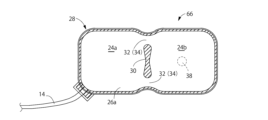
図1~3に、本発明の第一の実施形態としての体圧支持用の流体セル10を示す。本実施形態の流体セル10は、全体として4個の上下セル12a~dを平面上に並べた構造とされている。各上下セル12は、内部に流体室を備えており、それらの流体室に対して管体14を通じて外部から流体としての空気が給排されるようになっている。そして、各上下セル12への空気の給排により、流体室の内圧が変更可能とされていると共に、各上下セル12が高さ方向に伸縮可能とされている。
1 to 3 show a
より詳細には、各上下セル12は、下段セル16の上に上段セル18を高さ方向に重ね合わせた2段セル構造とされている。4個の上段セル18は、互いに独立した袋状構造とされており、図2に示されているように、平面視において4角が丸められた正方形に近い角丸矩形状とされている。例えば角丸矩形状の平らな樹脂シート20a,20bの2枚を重ね合わせて外周縁部を溶着等で相互に固着することにより、両樹脂シート20a,20b間に流体室としての上段気室22を備えた上段セル18が構成され得る。なお、図2中のハッチング領域は、上段セル18を構成する上下樹脂シート20a,20bにおける外周縁部の固着部分を示している。
More specifically, each of the upper and lower cells 12 has a two-tier cell structure in which an
一方、4個の下段セル16は、全体につながった一つの袋状構造とされており、その内部が仕切られることによって、4個の下段気室24が区画形成されている。そして、各下段気室24が、各上段気室22の下方に位置せしめられて、上下セル12を構成している。
On the other hand, the four
このような下段セル16は、例えば4個の上段セル18の下方にわたって広がる大きさの平らな樹脂シート26a,26bの2枚を重ね合わせて外周縁部を溶着等で相互に固着することにより形成され得る。下段セル16を形成する上下の樹脂シート26a,26bは、上段セル18を形成する上下の樹脂シート20の略4枚分の大きさとされている。これにより、4つの下段セル16は、4つの上段セル18の下方にわたって広がる大きさをもった一つの共用セル28によって構成されている。
Such a
共用セル28は、樹脂シート26a,26b間に形成された一つの流体室を有しており、この一つの流体室が部分的に仕切られることによって、4個の上段セル18の下部にそれぞれ位置する4個の下段セル16が、それぞれ形成されている。なお、本実施形態では、各下段セル16が、各上段セル18に略対応した平面形状と大きさとされているが、大きさや形状を上下セル間で異ならせることも可能である。
The shared
すなわち、図3に示されているように、下段セル16を構成する上下の樹脂シート26a,26bは、隣接する縁部をオーバーラップさせて並べた4個の上段セル18の最外周縁を縁取ったような略角丸矩形状の平面形状とされている。なお、図2の平面視よりも図3の平面視の方が大きな寸法で図示されているのは、図2が図1に対応した気室の膨張状態を示すのに対して、図3では気室に空気が入っていない非膨張状態での平置き平面視だからである。
That is, as shown in FIG. 3, the upper and
また、下段セル16を構成する上下の樹脂シート26a,26bは、最外周縁部を縁取るようにして溶着等により相互に固着されており、両樹脂シート26a,26b間に一つの気室である流体封入領域が形成されている。更に、上下の樹脂シート26a,26bには、中央部分においても溶着等による固着領域30が設けられている。かかる中央部分の固着領域30は、4個の上段セル18に対応した区画方向に向かって延びている。
Further, the upper and
換言すれば、上下の樹脂シート26a,26bの中央部分に設けられた固着領域30は、共用セル28内の気室を4個の下段セル16に仕切って、各上段セル18の上段気室22の下側において略対応した形状の下段気室24を形成するように設けられている。本実施形態では、略角丸矩形状の平面形状を有する上下の樹脂シート26a,26bにおいて、中心を通って対向する各辺部の中央部分同士をつなぐ方向に延びる2本の線状の固着領域30a,30bが、互いに直交して設けられている。
In other words, the fixed
また、各線状の固着領域30a,30bは、樹脂シート26a,26bにおいて対向する各辺部の中央部分同士をつなぐ方向に延びているが、対向する辺部間の全長に亘って連続して延びていない。要するに、対向する辺部間にまたがって延びる固着領域30a,30bには、何れも、長さ方向の少なくとも一箇所で分断されており、少なくとも一つの非連続部分32が設定されている。
In addition, each of the linear
これにより、上下の樹脂シート26a,26b間に形成された共用セル28内の一つの気室は、固着領域30a,30bによって仕切られて、各上段セル18の上段気室22の下方にそれぞれ位置する複数(本実施形態では4個)の下段気室24が形成されている。
As a result, one air chamber in the
なお、固着領域30a,30bは、長さ方向で幅寸法が変化しており、樹脂シート26a,26bの重ね合わせ面間において外周縁の固着領域と中央部分の固着領域30a,30bとで仕切られるようにして形成された各下段気室24の平面外周形状が、上段セル18と同様に、略角丸矩形状とされている。このように上下気室22,24が角丸矩形状とされていることにより、直角な角部を有する矩形状の気室に比して、膨らんだ場合の応力集中や大きな皺の発生が軽減され得る。
Note that the fixed
また、これら4個の下段気室24は、相互に完全に独立しておらず、固着領域30a,30bに設定された非連続部分32によって構成された通気孔34を通じて、相互に連通されている。なお、通気孔34による下段気室24相互間の連通は制限的であり、非連続部分32の寸法によって、通気孔34の断面積や長さをチューニングすることで、通気孔34による下段気室24間の流通抵抗を調節設定することができる。
Furthermore, these four lower air chambers 24 are not completely independent from each other, but are communicated with each other through ventilation holes 34 formed by
本実施形態では、図3中の左右方向をX方向とし、同上下方向をY方向として、直交する平面上のX-Yの2軸方向を想定すると、X方向に延びる固着領域30aには長さ方向の両端部分に非連続部分32からなる通気孔34が計2つ設けられていると共に、Y方向に延びる固着領域30bには長さ方向の両端部分と中央部分に非連続部分32からなる通気孔34が計4つ設けられている。これらの通気孔34は略同じ大きさとされていることで、本実施形態では、X方向(図3中の左右方向)で隣り合う下段気室24,24間での通気孔34を通じての流通抵抗に比して、Y方向(図3中の上下方向)で隣り合う下段気室24,24間での通気孔34を通じての流通抵抗の方が大きく設定されている。
In this embodiment, assuming two axes of X and Y on orthogonal planes, with the left and right direction in FIG. 3 being the X direction and the top and bottom directions being the Y direction, the fixed
そして、共用セル28の内部に形成された各下段気室24の上に、上段気室22を備えた上段セル18が重ね合わされており、共用セル28が固着領域30で仕切られて形成された4個の下段セル16の上に、それぞれ上段セル18が配置されている。また、下段セル16と上段セル18は、各中央部分において下段セル16の上側樹脂シート26bと上段セル18の下側樹脂シート20aとが溶着等で固着されることによって、上段気室22と下段気室24を内部に備えた上下セル12が形成されている。
An
かかる上下セル12は、下段セル16と上段セル18が相互に固着された中央部分において各樹脂シート26b,20aを貫通する連通路36を有している。この連通路36を通じて、上段セル18の上段気室22と下段セル16の下段気室24とが相互に連通されている。
The upper and lower cells 12 have a
なお、上段セル18と下段セル16との連結部分は、上段セル18や下段セル16の外周縁より一回り小さい角丸矩形状や円形状など、任意の外周形状をもって形成され得る。上段セル18と下段セル16の各外周部分は、中央の連結部分から外周に広がっている。これにより、上下セル12が膨らんだ状態では、図1からも判るように、上段セル18の下段セル16(共用セル28)への接続部分が括れ形状とされて、かかる括れ形状の接続部分での屈曲変形が容易に許容されることで、上段セル18が共用セル28に対して相対的に傾動が容易とされている。
Note that the connecting portion between the
また、上段セル18と下段セル16との連結部分に設けられた連通路36は、形状や大きさ、数などを適宜に設定可能であるが、本実施形態では、共用セル28内で隣り合う下段セル16,16間を連通する通気孔34の流通抵抗に比して、小さな流通抵抗となるように連通路36が設定されている。これにより、各上下セル12における上段セル18と下段セル16との間での流体移動が、隣り合う上下セル12,12間での流体移動よりも優先的に生ぜしめられ得るようになっている。
Furthermore, the shape, size, number, etc. of the
さらに、上述の如き複数(本実施形態では4個)の上下セル12a~d内の各気室に対して、外部から空気を給排するための管体14が設けられている。かかる管体14は、一方の開口端が共用セル28に接続されて、共用セル28の内部の流体室に連通されている。具体的には、例えば図示されているように、固着領域の幅を比較的に大きくとることのできる、隣接する下段気室24,24間に位置する共用セル28の幅方向中央部分に対して、管体14の一方の端部が差し入れられるように配置される。そして、共用セル28を構成する上下の樹脂シート26a,26b間で、管体14の当該端部を挟んだ状態で、溶着等により管体外周面を気密に固着することによって、管体14が流体セル10へ取り付けられる。
Furthermore, a
これにより、各上下セル12a~dは、下段気室24に接続された管体14を通じて、外部に対する空気の給排が行われ得る。なお、管体14の開口部に対して直近に位置する二つの下段気室24a,24cは、略直接に管体14を通じて空気の給排が可能であるが、管体14の開口部から最も離れて位置する残りの二つの下段気室24b,24dは、通気孔34や下段気室24a,24cを介して、管体14を通じての空気の給排が実現される。更に、各上下セル12a~dの上段気室22は、何れも、連通路36と下段気室24を介して、管体14を通じての空気の給排が実現される。
Thereby, each of the upper and
さらに、共用セル28へ先端が固着された管体14は、外部に向かって延び出して流体セル10の支持面上に敷設され、例えば特許文献2等にも記載されているように外部の給排用のバルブを介してポンプなどに接続される。それ故、管体14によっても、共用セル28延いては流体セル10に対して、流体セル10が設置される支持面上で或る程度の位置決め作用が発揮され得る。この管体14による位置決め作用を利用することで、流体セル10の装着面とされる支持面上への位置決め手段を簡素化することも可能であり、例えば共用セル28の底面において、ホック,スナップボタンや面ファスナーなどによる支持面に対する位置決め手段を、管体14の接続側に対して反対側に偏倚させて設置することもできる。
Furthermore, the
具体的には、本実施形態では、図3に示されているように、位置決め手段としてのスナップボタン38が、共用セル28において管体14の接続位置に対して、近くに位置する2個の下段気室24a,24cの底壁部分には無く、遠くに位置する2個の下段気室24b,24dの底壁の各中央部分に設けられている。
Specifically, in this embodiment, as shown in FIG. They are not provided in the bottom wall portions of the
ところで、本発明に係る流体セル10の各構成部材の材質は特に限定されるものでなく、例えば上下セルを構成する各樹脂シート20,26は、柔軟な可撓性シートが採用され得る。加工のし易さや耐久性,耐過重性,製造コストなどを考慮すると、樹脂シート20,26は、熱可塑性のエラストマシートが好ましく、例えばポリエチレン、ポリプロピレン、ポリスチレン、ポリアミド、ポリカーボネート、ポリテトラフルオロエチレンなどの合成樹脂シートが採用され得る。管体14は、金属でもよいが、加工や取り扱いやすさなどを考慮すると、樹脂チューブやメッシュ補強の複合樹脂チューブなどが好適に採用され得る。
By the way, the material of each component of the
また、上段セル18を構成する樹脂シート20は、上段セル18を膨らませた際に隣り合う上段セル18,18間に大きな隙間が発生しないように、共用セル28を構成する樹脂シート26,26に対する相対的な大きさや形状を設定されることが望ましい。例えば、図1,2に示されているように、流体セル10を膨張させた状態で、隣り合う上段セル18,18間で、溶着等された樹脂シート20の外周縁部が相互に重なり合うことようにして、隣り合う上段セル18,18間に隙間が実質的に発生しないようにできる。即ち、流体セル10内から空気を抜いた収縮状態では、隣り合う上段セル18,18の外周縁部が、溶着等された樹脂シート20の外周縁部よりも大きな幅寸法の領域で互いに重なり合うような大きさで、樹脂シート20を形成することが望ましい(第二実施形態の図13参照)。
Further, the resin sheet 20 constituting the
上述の如き構造とされた流体セル10によれば、4個の上下セル12a~dを構成する4個の下段セル16が、4個の上段セル18の下方にわたって広がる大きさの一つの共用セル28によって構成されている。これにより、上段セル18の数を維持して、各上段セル18による体圧作用面の変形への追従性などを確保しつつ、下段セル16の数や流体給排用の管体14を実質的に減らすことが出来て、構造や製造の簡略化などが図られ得る。
According to the
特に本実施形態では、4個の上下セル12a~dへの空気給排用の管体14が、共用セル28に接続された1本で行われるようになっている。それ故、複数の上下セル12を備えた流体セル10において、管体14の取りまわしや、管体14を通じての空気の給排用の設備、空気の給排の制御なども、簡略化が図られ得る。
In particular, in this embodiment, the
また、4個の下段セル16が、実質的に一つの共用セル28で構成されているものの、互いに隣り合う下段気室24a~d間での空気の流動特性を、各通気孔34(固着領域30a,30bに設定された非連続部分32)の大きさによって適宜に設定可能である。
Furthermore, although the four
それ故、例えば上段気室22と下段気室24との連通路36に比して各通気孔34の通気抵抗を大きく設定すれば、上下気室22,24による衝撃緩衝作用や速やかな圧力制御性能などを確保しつつ、隣り合う上下セル12,12間での過度に速やかな空気流動による体圧支持面の揺れを抑制したりすることなども可能になる。
Therefore, for example, if the ventilation resistance of each
また、例えば共用セル28内においてもX方向とY方向で隣り合う下段気室24,24間での通気孔34による空気の流通抵抗を異ならせるように設定すれば、X方向で隣り合う下段気室24,24間では比較的に速やかな空気流動を許容することで比較的速やかな体圧分散やクッション性能等を実現しつつ、Y方向で隣り合う下段気室24,24間での過度に速やかな空気流動を抑えて体圧支持面の揺れを抑制することなども可能になる。
Furthermore, for example, in the shared
なお、共用セル28内における下段気室24,24間の通気孔34や上下気室22,24間の連通路36は、給排用の管体14に比して、流通抵抗を小さくされることが望ましい。これにより、管体14を通じての圧力制御を、各下段気室24や各上段気室22に対して速やかに及ぼし易くできる。
In addition, the
さらに、本実施形態の流体セル10では、使用者の体圧が作用する体圧作用面として流体セル10の天面を構成する上段セル18が、小径の括れ状部を介して共用セル28上に設置されて首振り状の変形変位が比較的容易に許容されることから、使用者の体表面への追従性や体圧のサポート性に優れており、褥瘡の原因ともされる体表面へ作用する摩擦力の軽減も図られ得る。一方、下段セル16は、共用セル28によって複数個が一体的に構成されていることから、横方向の変形や変位が抑えられることとなり、上下セル12の全体としても横方向に倒れるような変形が抑えられ得る。それ故、例えば局所的に大きな体圧が作用した場合等においても、隣り合う上下セル12,12間への使用者の体の一部の入り込みや、底着きなどの発生が回避されやすい。
Furthermore, in the
しかも、本実施形態の流体セル10では、一つの下段セル16に一つの上段セル18が実質的に対応して上下方向に延びる略直線的な中心軸上で重なって上下セル12が構成されている。それ故、下段セル16と上段セル18における各空気給排に伴う高さ方向の伸縮中心軸が略一致して、上下セル12の高さ方向の伸縮中心軸とされていると共に、複数(本実施形態では4個)の上下セル12の高さ方向の伸縮中心軸が略平行とされている。その結果、例えば一つの下段セル16の上に複数の上段セル18を設けた場合に懸念される、下段セル16の膨張/縮小に伴う下段セル16における上段セル18の支持面の傾斜が抑えられて、各上下セル12における膨張時の傾きやそれに伴う上段セル18,18間での隙間の発生なども軽減され得る。
Moreover, in the
加えて、本実施形態の流体セル10では、図1,2にも示されているように、平面視において膨張状態における上段セル18の全体で下段セル16が重なるように、上段セル18と下段セル16の膨張時における平面視での大きさや形状が略同じとされている。それ故、上段セル18だけでなく下段セル16も、体圧支持面の平面方向で略隙間なく膨張するようになっており、上段セル18と下段セル16における上下二段の気室22,24によって、隙間に起因する底着き等も回避されて良好で略一様なクッション性能を発揮し得る体圧作用面が広い面積をもって構成され得る。
In addition, in the
ところで、本発明に係る流体セルを用いれば、例えばベッドや椅子などにおける体圧支持面を構成するマットレスなどを実現することができる。図4~5には、上述の如き第一の実施形態に係る流体セル10の複数を用いて構成された流体セル式マットレス40を備えたベッド42が例示されている。
By the way, by using the fluid cell according to the present invention, it is possible to realize, for example, a mattress that constitutes a body pressure supporting surface in a bed, a chair, or the like. 4 and 5 illustrate a
本実施形態のベッド42は、ベッドフレーム44の上に設置されるマットレス本体46を備えている。マットレス本体46は、底部全体に亘って広がるベースクッション48と、該ベースクッション48の上に重ね合わされた頭部クッション50及び左右クッション52,52を備えており、更に、これら頭部クッション50と左右クッション52,52で囲まれたベースクッション48の中央部分に流体セル式マットレス40が設置されている。また、マットレス本体46の最上層には、上面全体に亘って広がるカバークッション54が重ね合わされており、頭部クッション50と左右クッション52,52と流体セル式マットレス40の全体がカバークッション54で覆われている。
The
なお、マットレス本体46の保護などの目的で、マットレス本体46にカバーを付けることもできる。カバーは、例えばマットレス本体46の上面だけを覆うパッドタイプや、上面と外周面を覆うカバータイプ、マットレス本体46の全体を収容する袋タイプのもの等が適宜に採用され得る。
Note that a cover may be attached to the
ベースクッション48や頭部クッション50,左右クッション52,52,カバークッション54の材質は限定されるものでなく、要求される形状安定性や緩衝特性などを考慮して、例えばウレタンフォームなどの発泡樹脂が採用され得る。因みに、ベースクッション48は硬質であってもよいし、カバークッション54は非クッション性の可撓性シートなどであってもよい。
The materials of the
また、ベースクッション48や頭部クッション50,左右クッション52,52の大きさや形状なども要求特性に応じて任意に設定可能であって限定されるものでなく、ベッドの足部側にクッションを追加したり、ベッドの長さ方向や幅方向の中間部分などにクッションを追加したりすることも任意である。これらのクッションの形状や配置態様などに応じて、流体セル式マットレス40の形態も適宜に変更設定され得る。
In addition, the size and shape of the
流体セル式マットレス40は、図1~3に示された流体セル10の複数個を並置して、頭部クッション50と左右クッション52,52で囲まれたベースクッション48の中央部分を、それら流体セル10で埋めつくすようにして構成されている。本実施形態では、流体セル10をベッド幅方向に3個、ベッド長さ方向に8個、並設することによって構成されている。即ち、全体として上段セル18が、ベッド幅方向に6個、ベッド長さ方向に16個、互いに略隙間なく並んだ状態で膨らんで体圧作用面を構成するようになっている。
The
なお、本実施形態では、流体セル式マットレス40の上を全体に亘って覆うように調節クッション56が配置されており、流体セル式マットレス40によるクッション性の調節や、流体セル式マットレス40と頭部クッション50及び左右クッション52,52との高さの調節、多数並んだ上段セル18による体圧支持面における支持特性の均質化などが図られている。尤も、かかる調節クッション56は必須ではないし、調節クッション56をカバークッション54の下面に固着することで、頭部クッション50や左右クッション52,52の内側への調節クッション56の嵌まり込み作用を利用して、カバークッション54を面方向で位置決めすることも可能である。
In addition, in this embodiment, the
また、流体セル式マットレス40を構成する多数の流体セル10は、各別に独立して準備されたものをベースクッション48上に設置してもよいが、適数個の流体セル10を予め組み合わせてユニット化したものを設置してもよい。
Further, although the large number of
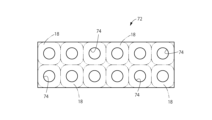
例えば図6~7に例示されているように、ベッド42の幅方向に配置されることとなる3個の流体セル10a,10b,10cを、並置した状態で組み合わせた流体セルユニット60として準備され得る。なお、複数の流体セル10をユニット化するに際しては、ユニット体としての取り扱いを容易にするために、複数の流体セル10を例えば接着や溶着等により或いはバンド等を用いてつないだりすることが望ましい。また、後述する別態様の流体セルユニット(70)のように、上下セル12の括れ状部を相互につなぐように広がる中間シート(72)を採用することで、複数の流体セル10をユニット化することも可能である(第二実施形態の図14参照)。
For example, as illustrated in FIGS. 6 and 7, a
かかる流体セルユニット60では、各上下気室22,24が膨らんだ状態で、隣り合う上段セル18,18間や共用セル28,28間において実質的に隙間が無くなるように、非膨張状態では周縁部が相互に重なり合った状態で配設されている。各流体セルユニット60の位置決めは、例えば図5及び図8に示されているように、ベースクッション48上に敷設されたベースシート62において、予め所定位置にスナップ受け64が設けられており、各スナップ受け64に対して、流体セルユニット60の共用セル28の底面に設けられた前述のスナップボタン38が嵌め合わされて固定されることにより行われ得る。
In such a
尤も、流体セルユニット60を構成する各流体セル10では、スナップボタン38のスナップ受け64への嵌合固定だけでなく、管体14によっても、位置決め作用が発揮される。それ故、スナップボタン38からなる位置決め手段の数が少なくて済み、スナップボタン38やスナップ受け64の部材への取付作業や、相互の嵌合作業について労力軽減が図られ得る。
However, in each
また、流体セルユニット60の各共用セル28から延びだした空気給排用の管体14は、ベッド幅方向で同じ側に引き出されている。そして、複数本(本実施形態では3本)の管体14が束ねられた状態で、例えばベッド42の幅方向となる左右の何れか一方のクッション52を貫通して外部に取り出され、特許文献2に記載されている如き弁体やポンプなどの空気圧制御手段に接続されることとなる。
Further, the air supply/
本実施形態では、各共用セル28の幅方向の中央部分から管体14が同一方向に向かって延びだしている。それ故、一つの共用セル28から直線的に延びる管体14は、ベッド幅方向(ユニットの長さ方向)で隣り合う別の共用セル28の幅方向の中央部分の下側を通ることとなる。ここにおいて、各共用セル28の幅方向の中央部分は、隣り合う下段セル16,16間を延びる固着領域30とされていることから、管体14を、共用セル28において隣り合う下段気室24,24間の隙間である当該固着領域30の下方を通る状態で敷設することができる。
In this embodiment, the
それ故、各管体14の敷設領域を、ベースクッション48上において優れたスペース効率で確保できる。また、管体14が、固着領域30の下から下段気室24の下側へ多少は入り込んでも、下段気室24の外周部分は気室膨張によって浮き上がる領域であって、体圧作用時にも最大圧力の管体14への作用が回避される。従って、仮に管体14が比較的に軟質な樹脂チューブ等で形成されていても、管体14の潰れによる圧力制御への悪影響などが回避され得る。要するに、気室膨張によって浮き上がることでスペース確保し易い下段気室24,24間の領域を巧く利用して、管体14の配設スペースを得ることが可能となる。
Therefore, the installation area for each
また、隣り合う下段気室24,24間の同じ領域に配された複数本の管体14をテープなどで束ねても良く、それによって管体14を介しての各共用セル28に対する位置決め作用の向上も図られ得る。なお、複数の共用セル28を並べる場合に、各共用セル28に接続された管体14を同一方向に延びださせることは、本発明において必須ではなく、例えば幾つかの管体14を他の管体14とは反対方向に延びだすように配設することもできる。
Further, a plurality of
上述の如き構造とされた流体セル式マットレス40では、体圧支持面を構成する上段セル18の個数を充分に確保しつつ、下段セル16の複数をまとめて共用セル28で構成した流体セル10を採用したことで、例えば特許文献2に記載の如き各独立した上下セルの複数の並置した従来構造の流体セル式マットレスに比して、実質的なセルの構成数を少なくできて、流体セル式マットレス40の構造の簡略化や低コスト化などが図られ得る。また、従来構造の流体セル式マットレスに比して、空気給排用の管体14の数も少なくできることから、管体14の配設も容易になると共に、管体14を通じての空気圧制御の簡略化も容易となる。
In the
そして、各流体セル10が管体14を通じて空気圧制御されることにより、特許文献2に記載の如き各独立した気室を備えた上下セルの複数を並置した従来構造の流体セル式マットレスと同様に、使用者の体重などの載荷重に対応した荷重支持特性を提供することができる。例えば、各流体セル10又は各上下セル12に対応する部位に荷重センサを配置して、それら荷重センサの検出値に基づいて、或いは各気室の空気圧の検出値に基づいて、荷重が所定範囲に亘って分散されるように各流体セル10の空気圧を制御することができる。なお、荷重センサは、例えば各流体セル10を構成する少なくとも一つの上段セル18とカバークッション54との間に配置することができ、本実施形態では調節クッション56と上段セル18又はカバークッション54との間に配置することができる。
By controlling the pneumatic pressure of each
特に本実施形態では、使用者の体圧支持面が、首振り状に傾動可能とされた多数の独立した上段セル18によって構成されていることから、例えば図9に示すように、使用者Aの体表面に略沿った体圧支持面をもって広い面積で当接して、体圧を効率的に分散させた状態で支持することができる。なお、本実施形態では、多数の上段セル18による体圧支持面に対して、使用者Aの体表面は、薄いシート状のクッション54,56を介して当接されることとなる。尤も、このようなクッションを設けることなく、必要に応じて例えば薄いシーツ等を介して、直接的に上段セル18の体圧支持面によって使用者Aの体表面を当接支持せしめてもよい。
In particular, in this embodiment, since the user's body pressure support surface is constituted by a large number of independent
また、1つの流体セル10を構成する4個の上段セル18の上段気室22は、連通路36と下段気室24、更に通気孔34を通じて、相互に連通されている。それ故、4個の上段セル18の上段気室22間で、各作用する体圧に応じて、空気流動が生ぜしめられて、体圧分散が図られると共に、4個の上段セル18の上面によって構成される体圧支持面が使用者Aの体表面に沿うように速やかに変形し得る。尤も、4個の上段セル18間での空気の流動は、通路断面積が絞られた連通路36や通気孔34によって制限されることから、過度な空気流動に起因する揺れや揺れ戻しなどの不快感は抑えることができる。
Further, the
さらに、異なる流体セル10間でも、管体14を介して、更に必要に応じてバルブの制御によって、空気流動が生ぜしめられることで、複数の流体セル10の多数の上段セル18間で体圧分散が図られると共に、それら多数の上段セル18で構成される体圧支持面の全体が使用者Aの体表面に沿って変形されることとなる。
Furthermore, air flow is generated between different
なお、流体セル10の気室間での空気流動を許容する通気孔34の流通抵抗よりも管体14を介しての異なる流体セル10間での空気流動の流通抵抗が大きく設定されることが望ましい。これにより、管体14を通じて共用セル28に及ぼされる圧力変化を、共用セル28内の複数の下段気室24や更に上段気室22に対して、速やかに及ぼすさとが可能になって、一つの流体セル10内で異なるセルに対して大きな時間差をもって圧力変化が及ぼされることに起因する体圧支持面の不必要な揺れなども抑えられる。また、複数の共用セル28間を管体14を通じて相互に連通する場合でも、体圧変動に際して一つの流体セル10における複数のセル間での流体移動を優先的に生ぜしめつつ、異なる流体セル10間での流体移動を許容することで、圧力分散を次第に拡大させて広い領域での大きな揺れや揺れ戻しなどを抑えることも可能になる。
Note that the flow resistance of air flow between different
ところで、上述の実施形態では、4個の上下セル12を備えた流体セル10について説明したが、1個の共用セル28において構成される下段気室24の数ひいては流体セル10を構成する上下セル12の数は限定されるものでない。
By the way, in the above-described embodiment, the
例えば図10~12に示されている第二の実施形態のように、2個の上下セル12a,12bを備えた流体セル66を構成することも可能である。なお、図10,11はセルの膨張状態を示しており、図12はセルの非膨張状態を示している。また、本実施形態では、第一の実施形態と同様な構造とされた部材及び部位について、第一の実施形態と同一の符合を付して詳細な説明を省略する。なお、図11中のハッチング領域は、図2,6と同様、上下樹脂シートの固着領域を示す。
For example, it is also possible to configure the
すなわち、本実施形態の流体セル66は、独立した2個の上段セル18,18と、1個の共用セル28の内部に2個の下段気室24,24が形成されることによって構成された2個の下段セル16,16を備えている。また、共用セル28を構成する上下の樹脂シート26,26において2個の下段気室24,24間を仕切る固着領域30には、長さ方向の両側に非連続部分32が設けられており、かかる非連続部分32によって下段気室24,24間を連通する通気孔34が構成されている。
That is, the
共用セル28には、一方の下段気室24側の端部に位置して、気室に対する空気給排用の管体14が接続されている。なお、管体14における共用セル28への接続側端部は、共用セル28の一方の隅部からやや側方に突出しており、後述する流体セルユニット(70)において他の共用セル28の側面に沿って延びるようになっている。また、共用セル28を装着面へ位置決めするためのスナップボタン38は、管体14が接続された方の下段気室24には設けられておらず、管体14の接続部位から最も離れて位置する、他方の下段気室24の底部を構成する樹脂シート26に設けられている。
A
このような本実施形態の流体セル66も、第一の実施形態の流体セル10と同様に、例えば複数並べて設置することでベッド用のマットレスを構成し得る。その際、前述の流体セル式マットレス40において例示したように、複数個の流体セル66を予めまとめてユニット化することもできる。
Similar to the
具体的には、例えば図13~14に示されているように、合計6個の流体セル66を、流体セル66の長手方向(下段気室24の配列方向)に3個、流体セル66の短手方向に2個、配置して一つの流体セルユニット70を構成することができる。なお、図13はセルの非膨張状態での図示であって、互いに隣り合う上段セル18の外周縁部が重なっていることが判る。図14はセルの膨張状態での斜視図である。
Specifically, as shown in FIGS. 13 and 14, for example, a total of six
本実施形態では、図15に示されている中間シート72を用いて、6個の流体セル66を纏めてユニット化したものである。かかる中間シート72は、樹脂等の可撓性のシートで構成されており、各流体セル66の配設位置にはセル装着孔74が形成されている。このセル装着孔74は、上段セル18及び下段セル16の外寸よりは小さいが、それら両セルが中央で固着された括れ状の連結部分の外寸よりは大きい貫通孔とされている。そして、各セル装着孔74に対して各上段セル18が挿し通されて、くびれ状の連結部分がセル装着孔74内に位置するようにして装着されることで、全ての流体セル66が、各くびれ状とされた上下セルの高さ方向中間部分において、中間シート72で相互に位置決めされて連結状態とされている。
In this embodiment, six
この流体セルユニット70は、第一の実施形態の流体セル10を用いた前述の流体セルユニット60と同じ数の上下セル12を有している。従って、前述の実施形態と同様に、当該流体セルユニット70をベッド長さ方向に8個並べることによって、前述の実施形態と同様な流体セル式マットレス40を構成することができる。
This
本実施形態の流体セル66においても、第一の実施形態の流体セル10と同様に、各独立した上段セル18,18の上段気室22にそれぞれ連通された下段気室24,24を備えた下段セル16,16が、一つの共用セル28で構成されており、且つ、共用セル28内の下段セル16,16間での空気流通抵抗も通気孔34によって調節設定することが可能である。
Similarly to the
それ故、本実施形態の流体セル66においても、各上段セル18による体圧作用面の変形への追従性などを確保しつつ、下段セル16の数や流体給排用の管体14を実質的に減らして構造や製造の簡略化などが図られ得るといった、第一の実施形態の流体セル10と同様な効果が達成され得る。また、かかる流体セル66を用いて構成された流体セル式マットレスにあっても、第一の実施形態の流体セル10を用いて構成された流体セル式マットレス40と同様な効果が達成され得ることとなる。
Therefore, in the
なお、本実施形態の流体セルユニット70を用いて流体セル式マットレスを構成した場合では、隣り合う流体セル66,66における下段気室24,24間(共用セル28,28間)の下部領域を利用して管体14が配設されることとなる。この場合でも、気室膨張によって浮き上がる領域を利用して、管体14への圧力作用を軽減しつつ、管体14を良好なスペース効率をもって配設することが可能になる。
In addition, when a fluid cell type mattress is constructed using the
以上、本発明の実施形態について詳述してきたが、本発明はその具体的な記載によって限定されない。例えば、上段セル18や下段セル16、共用セル28の具体的な形状は、限定されるものでなく、上面視で円形状や長円形状、長方形状などのように任意に設定されて得る。
Although the embodiments of the present invention have been described in detail above, the present invention is not limited by the specific description. For example, the specific shapes of the
また、前記実施形態の流体セル式マットレス40のように、複数の流体セル10を並べて設置するような場合には、隣り合う流体セル10の共用セル28を形成する樹脂シート26を連続したシートで構成してもよい。具体的には、例えば前記第一の実施形態のように流体セルユニット60を構成する複数の流体セル10が直列的配置された態様では、各共用セル28における上下の少なくとも一方の樹脂シート26を、ユニット長手方向で隣り合う複数の共用セルに跨がってのびる一つの連続した樹脂シートで構成することも可能である。或いは前記第二の実施形態のように流体セルユニット70を構成する複数の流体セル66が並列的配置された態様では、各共用セル28における上下の少なくとも一方の樹脂シート26を、ユニット短手方向で隣り合う複数の共用セルに跨がってのびる一つの連続した樹脂シートで構成することも可能である。
Further, when a plurality of
なお、ベッド用の流体セル式マットレス40の場合には、流体セル10(共用セル28)のベッド幅方向のサイズが大きくなりすぎると体圧分散や横揺れへの影響が懸念されることから、ベッド幅方向における流体セル10(共用セル28)の設置数は、2個以上が好ましく、より好適には3個以上とされる。
In the case of the
また、上段セル18は、完全に独立している他、例えば上段気室22が封止された外周縁のシート状部分が相互に連結されることで、隣接する上段セル18,18が互いに反対側に首振り状に変形して過度に離れてしまうことを防止することなども可能である。
In addition to being completely independent, the
また、上段気室22や下段気室24には、発泡ウレタンなどの弾性体を収容することもできる。弾性体を収容することで、衝撃的な大荷重の入力時におけるセルの底着きの防止や、荷重の解除時におけるセルの復元速度の向上なども図られ得る。
Further, the
さらに、下段セル16や上段セル18は、樹脂シートを上下に重ね合わせて外周部分を溶着した構造に限定されず、筒状成形体やブロー成形体などを用いて形成することなども可能である。また、下段セル16や上段セル18を構成する樹脂シート20,26も、平らなシートに限定されるものではなく、例えば膨張状態のセル形状を考慮して、予め凹状又は凸状とされた平面でない樹脂シートを用いても良い。
Furthermore, the
また、共用セル28への管体14の取付構造も、例示の如き樹脂シート間への挟み込みによる固着に限定されず、例えば樹脂シートを貫通して管体14を取り付けたり、樹脂シートに予め管体14の嵌入用の筒状ポート部を形成することも可能である。
Furthermore, the structure for attaching the
また、流体セルは、下段セル16と上段セル18を備えていれば良く、例えば下段セル部の下側に最下段セル部が設けられるなどして、全体として高さ方向に三段以上の多段セル構造とされていても良い。
Further, the fluid cell only needs to include a
流体セル式マットレスを構成する際に、複数の流体セルをまとめてユニット化することは必須ではない。また、予めユニット化する場合でも、流体セルユニットを構成する流体セルの数が限定されないことは勿論であり、例示のようにベッド幅方向に延びる長手のユニットを構成する態様の他、ベッド長さ方向に延びる長手のユニットを構成することも可能であって、ユニットの形状やサイズなども自由に設定できる。 When constructing a fluid cell type mattress, it is not essential to combine a plurality of fluid cells into a unit. Furthermore, even when unitizing in advance, the number of fluid cells constituting the fluid cell unit is of course not limited. It is also possible to configure a longitudinal unit extending in the direction, and the shape and size of the unit can be freely set.
また、共用セル28内の流体室において、非連続的に延びる固着領域30で部分的に仕切られることにより複数の下段気室24が区画形成される態様は、共用セル28において隣り合って形成された下段気室24,24間を連通する通気孔34を形成する態様の固着領域30であれば良く、隣り合う下段気室24,24間を完全に気密に分断しない固着領域であればよい。例えば、固着領域が、長さ方向の端部で非連続であってもよいし、中間部分で非連続であってもよく、また、長さ方向の複数箇所が非連続であってもよい。非連続部の大きさや形状によって通気孔の流通抵抗を調節することが可能であり、例えば蛇行や屈曲等して延びる形状の通気孔を採用することも可能である。
Furthermore, in the fluid chamber in the shared
本発明に従う流体セルを用いて流体セル式マットレスを構成する場合に、全体を本発明に従う流体セルで構成する必要はない。例えば 体圧作用面の特定のエリアを、特許文献1や特許文献2に記載の如き従来構造の流体封入式のセルによって構成してもよい。
When constructing a fluid cell mattress using fluid cells according to the invention, it is not necessary to construct the entire mattress with fluid cells according to the invention. For example, a specific area of the body pressure acting surface may be configured by a fluid-filled cell having a conventional structure as described in
また、流体セル式マットレスを構成する流体セルにおいて、共用セルのX方向の通気孔とY方向の通気孔における流通抵抗の大小は限定されるものでなく、同じであってもよいし、何れの方向が他の方向に比して大きくてもよい。例えば一つの流体セル式マットレスにおいて、エリアなどによって、X方向とY方向の流体流通抵抗の大小を反対に設定することも可能である。 In addition, in the fluid cells constituting the fluid cell mattress, the magnitude of the flow resistance in the X-direction ventilation hole and the Y-direction ventilation hole of the shared cell is not limited, and may be the same, or either The direction may be larger than other directions. For example, in one fluid cell type mattress, it is also possible to set the fluid flow resistance in the X direction and the Y direction to be opposite in magnitude depending on the area or the like.
また、流体セルを構成する共用セルに複数の給排口を設けてもよい。更にまた、共用セルへの流体給排用の管体は、各共用セル毎に独立して配管してもよいが、例えば一本の配管上に分岐を設けることで、一本の配管を複数の共用セルに接続することも可能である。そして、当該配管を一つの給排制御弁に接続すれば、当該配管に対して分岐接続された複数の共用セルに対して共通の流体給排制御を行うことができる。なお、当該配管から分岐した各分岐路上に給排制御弁を設ければ、一本の配管を用いて、複数の許容セルに対して異なる流体給排の制御を実行することも可能である。 Further, a plurality of supply/discharge ports may be provided in the shared cell that constitutes the fluid cell. Furthermore, the pipes for supplying and discharging fluid to and from the shared cells may be installed independently for each shared cell, but by providing a branch on one pipe, for example, one pipe can be connected to multiple pipes. It is also possible to connect to a shared cell. If the piping is connected to one supply/discharge control valve, common fluid supply/discharge control can be performed for a plurality of shared cells branch-connected to the piping. Note that if a supply/discharge control valve is provided on each branch path branching from the pipe, it is also possible to perform different fluid supply/discharge controls for a plurality of allowable cells using one pipe.
また、流体セルを装着面に対して位置決めする手段は、例示の如き着脱式である必要はなく、着脱が不要であれば接着や溶着なども採用され得る。なお、かかる位置決め手段は、前述のように共用セルへ接続された管体による位置決め作用を利用することを考慮すると、好適には管体が接続された流体給排口の最も近くに位置する下段気室の形成領域を外れて、別の下段空気室の底壁部の略中央に設けられる。位置決め手段を、下段気室の底壁部の略中央に設けることにより、例えば共用セルが膨らんだ際に、仮に位置決め手段がなくても装着面への当接状態に維持される部位を装着面へ位置決めすることができて、下段気室の膨張形態への影響を軽減することができる。 Further, the means for positioning the fluid cell with respect to the mounting surface does not need to be detachable as illustrated, and adhesive, welding, etc. may be employed if attachment and detachment are not required. In addition, considering that the positioning means utilizes the positioning effect of the pipe connected to the common cell as described above, it is preferable that the positioning means is located at the lower stage located closest to the fluid supply/discharge port to which the pipe is connected. It is provided at approximately the center of the bottom wall of another lower air chamber outside the area where the air chamber is formed. By providing the positioning means approximately in the center of the bottom wall of the lower air chamber, for example, when the shared cell is inflated, the part that can be maintained in contact with the mounting surface even without the positioning means can be fixed to the mounting surface. It is possible to reduce the influence on the inflation form of the lower air chamber.
さらに、本発明に係る流体セルによって構成される体圧支持面は、例示の如きベッドの体圧支持面に限定されない。例えば、着座姿勢の体圧を支持する面を、本発明に係る流体セルによって構成することで、乗り物用のシートを含む椅子の着座面や背もたれなどの体圧支持面を構成する流体セル式マットレスを提供することも可能である。そして、実現される体圧支持面の要求特性などに応じて、上下セル12や流体セル10の形状や配列方向等も任意に設定可能であり、例えば体圧支持面の平面形状が円形などであっても良く、平面形状が円弧状や円形状とされた共用セルの上に、平面形状が円形状や円弧状などの上段セルの複数を設置すると共に、共用セルの固着領域を円形や円弧状等に湾曲してのびるように形成することも可能である。
Furthermore, the body pressure supporting surface constituted by the fluid cell according to the present invention is not limited to the body pressure supporting surface of a bed as illustrated. For example, a fluid cell type mattress that constitutes a body pressure supporting surface such as a seating surface or a backrest of a chair including a vehicle seat by configuring the surface that supports body pressure in a sitting posture with the fluid cells according to the present invention. It is also possible to provide The shape and arrangement direction of the upper and lower cells 12 and
10 流体セル
12 上下セル(第一実施形態では4個)
14 管体
16 下段セル
18 上段セル
20 樹脂シート(上段セル用)
22 上段気室
24 下段気室
26 樹脂シート(下段セル用)
28 共用セル
30 固着領域
32 非連続部分
34 通気孔
36 連通路
38 スナップボタン(位置決め手段)
40 流体セル式マットレス
42 ベッド
44 ベッドフレーム
46 マットレス本体
48 ベースクッション
50 頭部クッション
52 左右クッション
54 カバークッション
56 調節クッション
60 流体セルユニット
62 ベースシート
64 スナップ受け
66 流体セル
70 流体セルユニット
72 中間シート
74 セル装着孔
10 Fluid cell 12 Upper and lower cells (four in the first embodiment)
14
22 Upper air chamber 24 Lower air chamber 26 Resin sheet (for lower cell)
28
40
Claims (7)
前記下段セルが、複数の前記上段セルの下方にわたって広がる上シートと下シートの重ね合わせ面間に流体室が形成された共用セルによって構成されており、該共用セルにおいて外部からの流体の給排口が設けられていると共に、
該上シートと該下シートとが前記複数の上段セルに対応した区画方向に向かって非連続的に延びる固着領域で部分的に仕切られることによって、前記共用セルにおいて各該上段セルに対応した位置に下段気室が区画形成されていると共に、隣り合う該下段気室間が該固着領域の非連続部分で構成された通気孔を通じて連通されており、
該下段気室間を連通する該通気孔の流通抵抗が、該下段気室と該上段セルの内部とを連通する連通路の流通抵抗に比して大きくされている体圧支持用の流体セル。 A fluid cell for supporting body pressure, comprising a lower cell and an upper cell that communicate with each other, and is expandable and retractable in the height direction by supplying and discharging fluid to the lower cell and the upper cell,
The lower cell is constituted by a shared cell in which a fluid chamber is formed between the stacked surfaces of an upper sheet and a lower sheet that extend below the plurality of upper cells, and in the shared cell, fluid is supplied and discharged from the outside. Along with having a mouth,
The upper sheet and the lower sheet are partially partitioned by a fixed region extending discontinuously in the partition direction corresponding to the plurality of upper cells, so that a position corresponding to each upper cell in the shared cell is formed. A lower air chamber is defined in the lower air chamber, and adjacent lower air chambers are communicated with each other through a vent formed by a discontinuous portion of the fixed area,
A fluid cell for body pressure support, wherein the flow resistance of the ventilation hole that communicates between the lower air chambers is greater than the flow resistance of the communication path that communicates the lower air chamber and the inside of the upper cell. .
該共用セルの前記下段気室間を該X方向に連通する前記通気孔の流通抵抗と、該共用セルの前記下段気室間を該Y方向に連通する前記通気孔の流通抵抗とが、互いに異ならされている請求項1に記載の体圧支持用の流体セル。 A plurality of the upper cells are arranged above the shared cell in each of the X direction and the Y direction that are orthogonal to each other,
The flow resistance of the vent hole that communicates between the lower air chambers of the common cell in the X direction and the flow resistance of the vent hole that communicates the lower air chambers of the common cell in the Y direction are mutually The fluid cell for body pressure support according to claim 1, wherein the fluid cell is different.
該位置決め部材が、前記給排口の最も近くに位置する前記下段気室の形成領域を外れた位置に設けられている請求項1~3の何れか一項に記載の体圧支持用の流体セル。 The lower sheet is provided with a positioning member with respect to the cell installation surface,
The fluid for body pressure support according to any one of claims 1 to 3, wherein the positioning member is provided at a position outside the formation area of the lower air chamber located closest to the supply/discharge port. cell.
該接続部分を貫通して前記連通路が設けられている請求項1~4の何れか一項に記載の体圧支持用の流体セル。 A connecting portion of the upper cell to the shared cell is shaped like a constriction so that the upper cell can be tilted relative to the shared cell,
The fluid cell for supporting body pressure according to any one of claims 1 to 4, wherein the communication passage is provided through the connecting portion.
Priority Applications (1)
| Application Number | Priority Date | Filing Date | Title |
|---|---|---|---|
| JP2020030511A JP7355679B2 (en) | 2020-02-26 | 2020-02-26 | Fluid cell for body pressure support |
Applications Claiming Priority (1)
| Application Number | Priority Date | Filing Date | Title |
|---|---|---|---|
| JP2020030511A JP7355679B2 (en) | 2020-02-26 | 2020-02-26 | Fluid cell for body pressure support |
Publications (2)
| Publication Number | Publication Date |
|---|---|
| JP2021132815A JP2021132815A (en) | 2021-09-13 |
| JP7355679B2 true JP7355679B2 (en) | 2023-10-03 |
Family
ID=77662100
Family Applications (1)
| Application Number | Title | Priority Date | Filing Date |
|---|---|---|---|
| JP2020030511A Active JP7355679B2 (en) | 2020-02-26 | 2020-02-26 | Fluid cell for body pressure support |
Country Status (1)
| Country | Link |
|---|---|
| JP (1) | JP7355679B2 (en) |
Citations (6)
| Publication number | Priority date | Publication date | Assignee | Title |
|---|---|---|---|---|
| US5907878A (en) | 1997-10-10 | 1999-06-01 | Thomas; Paul B. | Air spring bedding system |
| JP2002272563A (en) | 2001-03-14 | 2002-09-24 | Matsushita Electric Works Ltd | Air cushion and chair provided with air cushion |
| JP2010125280A (en) | 2008-12-01 | 2010-06-10 | Kyushu Hitachi Maxell Ltd | Air mat |
| JP2017169911A (en) | 2016-03-24 | 2017-09-28 | 住友理工株式会社 | Fluid cell-type mattress and its control method |
| JP2017205154A (en) | 2016-05-16 | 2017-11-24 | 住友理工株式会社 | Fluid cell-type mattress |
| WO2019031271A1 (en) | 2017-08-11 | 2019-02-14 | 住友理工株式会社 | Fluid cell type mattress |
Family Cites Families (1)
| Publication number | Priority date | Publication date | Assignee | Title |
|---|---|---|---|---|
| US5638565A (en) * | 1995-04-07 | 1997-06-17 | Dielectrics Industries | Inflatable cushion |
-
2020
- 2020-02-26 JP JP2020030511A patent/JP7355679B2/en active Active
Patent Citations (6)
| Publication number | Priority date | Publication date | Assignee | Title |
|---|---|---|---|---|
| US5907878A (en) | 1997-10-10 | 1999-06-01 | Thomas; Paul B. | Air spring bedding system |
| JP2002272563A (en) | 2001-03-14 | 2002-09-24 | Matsushita Electric Works Ltd | Air cushion and chair provided with air cushion |
| JP2010125280A (en) | 2008-12-01 | 2010-06-10 | Kyushu Hitachi Maxell Ltd | Air mat |
| JP2017169911A (en) | 2016-03-24 | 2017-09-28 | 住友理工株式会社 | Fluid cell-type mattress and its control method |
| JP2017205154A (en) | 2016-05-16 | 2017-11-24 | 住友理工株式会社 | Fluid cell-type mattress |
| WO2019031271A1 (en) | 2017-08-11 | 2019-02-14 | 住友理工株式会社 | Fluid cell type mattress |
Also Published As
| Publication number | Publication date |
|---|---|
| JP2021132815A (en) | 2021-09-13 |
Similar Documents
| Publication | Publication Date | Title |
|---|---|---|
| JP5780643B2 (en) | mattress | |
| CA2744867C (en) | Configurable inflatable support devices | |
| US6568013B2 (en) | Fluid mattress assembly with check valves | |
| JP5331007B2 (en) | Air mat | |
| US5907878A (en) | Air spring bedding system | |
| JP7355679B2 (en) | Fluid cell for body pressure support | |
| JPWO2019031271A1 (en) | Fluid cell mattress | |
| WO2017043217A1 (en) | Body pressure support cushion and auxiliary cells constituting same | |
| JP2016087117A (en) | Fluid cell type mattress | |
| JP2002272563A (en) | Air cushion and chair provided with air cushion | |
| JP4010557B1 (en) | cushion | |
| JP6605128B2 (en) | Multilayer cushion and mattress with the same | |
| JP4815079B2 (en) | Cushion device | |
| JP2016034398A (en) | Cell for mattress and mattress using the same | |
| JP4733308B2 (en) | Cushion device | |
| JP2017205154A (en) | Fluid cell-type mattress | |
| JP7267348B2 (en) | FLUID CELL, MAT DEVICE, AND METHOD FOR MANUFACTURING FLUID CELL | |
| JP2019017729A (en) | Body pressure support cushion and its manufacturing method | |
| JP2020039485A (en) | Air cell type mattress | |
| JPS6323622A (en) | Air support for chair, chair utilizing air support and its production | |
| CN116889320A (en) | Inflatable bladder | |
| JP2016209531A (en) | Body pressure support cushion and mattress using the same | |
| JP4497883B2 (en) | cushion | |
| JP2017060599A (en) | Air cushion sheet and sheet | |
| JPH0898860A (en) | Bedsore preventing mat |
Legal Events
| Date | Code | Title | Description |
|---|---|---|---|
| A621 | Written request for application examination |
Free format text: JAPANESE INTERMEDIATE CODE: A621 Effective date: 20221107 |
|
| A977 | Report on retrieval |
Free format text: JAPANESE INTERMEDIATE CODE: A971007 Effective date: 20230911 |
|
| TRDD | Decision of grant or rejection written | ||
| A01 | Written decision to grant a patent or to grant a registration (utility model) |
Free format text: JAPANESE INTERMEDIATE CODE: A01 Effective date: 20230914 |
|
| A61 | First payment of annual fees (during grant procedure) |
Free format text: JAPANESE INTERMEDIATE CODE: A61 Effective date: 20230921 |
|
| R150 | Certificate of patent or registration of utility model |
Ref document number: 7355679 Country of ref document: JP Free format text: JAPANESE INTERMEDIATE CODE: R150 |