JP5331007B2 - Air mat - Google Patents
Air mat Download PDFInfo
- Publication number
- JP5331007B2 JP5331007B2 JP2009544561A JP2009544561A JP5331007B2 JP 5331007 B2 JP5331007 B2 JP 5331007B2 JP 2009544561 A JP2009544561 A JP 2009544561A JP 2009544561 A JP2009544561 A JP 2009544561A JP 5331007 B2 JP5331007 B2 JP 5331007B2
- Authority
- JP
- Japan
- Prior art keywords
- air
- air mat
- mat layer
- layer
- cell
- Prior art date
- Legal status (The legal status is an assumption and is not a legal conclusion. Google has not performed a legal analysis and makes no representation as to the accuracy of the status listed.)
- Expired - Fee Related
Links
- 230000008602 contraction Effects 0.000 claims description 22
- 239000010410 layer Substances 0.000 description 219
- 102100040428 Chitobiosyldiphosphodolichol beta-mannosyltransferase Human genes 0.000 description 34
- 238000009826 distribution Methods 0.000 description 5
- 210000001217 buttock Anatomy 0.000 description 2
- 101100495256 Caenorhabditis elegans mat-3 gene Proteins 0.000 description 1
- 206010011985 Decubitus ulcer Diseases 0.000 description 1
- JOYRKODLDBILNP-UHFFFAOYSA-N Ethyl urethane Chemical compound CCOC(N)=O JOYRKODLDBILNP-UHFFFAOYSA-N 0.000 description 1
- 208000004210 Pressure Ulcer Diseases 0.000 description 1
- 230000015572 biosynthetic process Effects 0.000 description 1
- 230000003247 decreasing effect Effects 0.000 description 1
- 239000013013 elastic material Substances 0.000 description 1
- 210000002414 leg Anatomy 0.000 description 1
- 238000000034 method Methods 0.000 description 1
- 238000012986 modification Methods 0.000 description 1
- 230000004048 modification Effects 0.000 description 1
- 230000000149 penetrating effect Effects 0.000 description 1
- 239000002356 single layer Substances 0.000 description 1
Images


Classifications
-
- A—HUMAN NECESSITIES
- A61—MEDICAL OR VETERINARY SCIENCE; HYGIENE
- A61G—TRANSPORT, PERSONAL CONVEYANCES, OR ACCOMMODATION SPECIALLY ADAPTED FOR PATIENTS OR DISABLED PERSONS; OPERATING TABLES OR CHAIRS; CHAIRS FOR DENTISTRY; FUNERAL DEVICES
- A61G7/00—Beds specially adapted for nursing; Devices for lifting patients or disabled persons
- A61G7/05—Parts, details or accessories of beds
- A61G7/057—Arrangements for preventing bed-sores or for supporting patients with burns, e.g. mattresses specially adapted therefor
- A61G7/05769—Arrangements for preventing bed-sores or for supporting patients with burns, e.g. mattresses specially adapted therefor with inflatable chambers
- A61G7/05776—Arrangements for preventing bed-sores or for supporting patients with burns, e.g. mattresses specially adapted therefor with inflatable chambers with at least two groups of alternately inflated chambers
-
- A—HUMAN NECESSITIES
- A61—MEDICAL OR VETERINARY SCIENCE; HYGIENE
- A61G—TRANSPORT, PERSONAL CONVEYANCES, OR ACCOMMODATION SPECIALLY ADAPTED FOR PATIENTS OR DISABLED PERSONS; OPERATING TABLES OR CHAIRS; CHAIRS FOR DENTISTRY; FUNERAL DEVICES
- A61G7/00—Beds specially adapted for nursing; Devices for lifting patients or disabled persons
- A61G7/05—Parts, details or accessories of beds
- A61G7/057—Arrangements for preventing bed-sores or for supporting patients with burns, e.g. mattresses specially adapted therefor
- A61G7/05715—Arrangements for preventing bed-sores or for supporting patients with burns, e.g. mattresses specially adapted therefor with modular blocks, or inserts, with layers of different material
Landscapes
- Health & Medical Sciences (AREA)
- Nursing (AREA)
- Life Sciences & Earth Sciences (AREA)
- Animal Behavior & Ethology (AREA)
- General Health & Medical Sciences (AREA)
- Public Health (AREA)
- Veterinary Medicine (AREA)
- Invalid Beds And Related Equipment (AREA)
- Mattresses And Other Support Structures For Chairs And Beds (AREA)
Description
本発明は、寝たきりの患者等のように病人が長時間、褥瘡がなく使用するのに適したエアマットに関する。 The present invention relates to an air mat suitable for use by a sick person for a long time without pressure sores such as a bedridden patient.
寝たきりの患者等に使用されるエアマットとして、例えば特許文献1には、上層の可変セル部と下層の固定セル部とからなる2層構造を有するエアマットが開示されている。このエアマットでは、可変セル部と固定セル部とは、いずれも細長いエアセルが多数並列することで構成され、固定セル部では、全てのエアセルが連通しているのに対して、可変セル部では、エアセルは複数のグループに分けられて、グループごとに連通している。そして、使用の際には、固定セル部は、全てのエアセルに給気が行われて常に膨張した状態になり、可変セル部は、各グループに交互にエアを給排気して、グループごとに膨張と収縮とを繰り返す。この結果、前記可変セル部の膨張及び収縮によって、エアマットに負荷される患者の体圧が分散されて床擦れが防止されると共に、膨張状態にある固定セル部が可変セル部を支持することで、患者がエアマット上で座位の姿勢を取った場合でも、患者の臀部がベッドの床面に着く底着き現象が防止されるとしている。
しかしながら、特許文献1では、固定セル部の上に設けた可変セル部が膨張・収縮を行うことで床擦れを防止するようにしているが、可変セル部が一層構造を有していることから、エアマットの空気圧分布は単純なものにしかならない。このため、可変セル部を単に膨張・収縮するだけでは、寝ている患者ごとに対応した圧力調整はできず、いろいろの患者に対応したエアマットとすることができないことから、患者の床擦れ防止機能としては不満足なものであった。
However, in
本発明は、患者がベッド上等に横臥した際に、患者の床擦れを確実に防止することができるエアマットを提供することを目的とする。 An object of the present invention is to provide an air mat that can reliably prevent a patient from rubbing the floor when the patient lies on the bed or the like.
第1の発明は、上下方向に積層された複数段のエアマット層を備えたエアマットにおいて、前記複数段のエアマット層の各層は、前記エアマットの幅方向に延びる可とう性中空エアセルが、前記エアマットの長手方向に並列することによって構成され、 前記複数段のエアマット層の上段エアマット層及び下段エアマット層の各層における該エアセルは、複数のグループに分けられて、グループごとに適当な時間間隔をもって空気が供給・排気されることで、グループごとに膨張・収縮を繰り返すようになっており、前記上段エアマット層と下段エアマット層との少なくとも一方において、所定位置で隣接する2つのエアセルの間には、前記エアマットの幅方向に延びるスリットが形成されている。 According to a first aspect of the present invention, there is provided an air mat including a plurality of air mat layers stacked in a vertical direction. Each of the plurality of air mat layers includes a flexible hollow air cell extending in a width direction of the air mat. The air cells in each of the upper air mat layer and the lower air mat layer in the plurality of air mat layers are divided into a plurality of groups, and air is supplied at appropriate time intervals for each group. By being exhausted, the expansion and contraction are repeated for each group, and at least one of the upper air mat layer and the lower air mat layer is provided between the two air cells adjacent at a predetermined position. A slit extending in the width direction is formed .
本発明によれば、エアマット層における上段エアマット層及び下段エアマット層のエアセルは、それぞれ前記グループごとに空気が供給・排気されるようになっているから、グループごとに適当な時間間隔をもって給排気することで、上段エアマット層、下段エアマット層は、グループごとに膨張と収縮とを繰り返す。そして、前記上段エアマット層及び下段エアマット層の膨張及び収縮を組み合わせて使用することにより、患者の体格や姿勢、体調等に応じた緻密な空気圧状態を実現することができるので、患者の床擦れが確実に防止される。特に、下段エアマット層がグループごとに膨張及び収縮し、上段エアマット層もグループごとに膨張及び収縮するので、これらの膨張及び収縮の組み合わせにより、患者に応じた空気圧状態を設定することができると共に、上段エアマット層の表面にバリエーション豊かな凹凸を形成することができる。これにより、エアマットは、その表面が患者の身体状況や姿勢等に適した凹凸状態となったエアマットとして機能する。 According to the present invention, the air cells of the upper air mat layer and the lower air mat layer in the air mat layer are supplied and exhausted for each group, so that air is supplied and exhausted at appropriate time intervals for each group. Thus, the upper air mat layer and the lower air mat layer repeat expansion and contraction for each group. Further, by using a combination of the expansion and contraction of the upper air mat layer and the lower air mat layer, it is possible to realize a precise air pressure state according to the patient's physique, posture, physical condition, etc. To be prevented. In particular, the lower air mat layer expands and contracts for each group, and the upper air mat layer also expands and contracts for each group, so that a combination of these expansion and contraction can set the air pressure state according to the patient, A wide variety of irregularities can be formed on the surface of the upper air mat layer. Thus, the air mat functions as an air mat whose surface is in an uneven state suitable for the patient's physical condition, posture, and the like.
また、下段エアマット層が常時所定以上の厚さを有するように下段エアマット層のエアセルに空気が供給・排気されるようにした場合には、患者の体重が局所的にエアマットに負荷されても底着きの発生が防止される。 In addition, when air is supplied to and exhausted from the air cells of the lower air mat layer so that the lower air mat layer always has a thickness greater than or equal to a predetermined thickness, even if the patient's weight is locally loaded on the air mat, Occurrence of arrival is prevented.
また、前記2つのエアセルの間にスリットが形成されていることで、エアマットに患者の自重が負荷された際に、前記2つのエアセルの移動量を大きく確保することができる。これにより、エアマットの表面を利用者の身体状況に適した凹凸の状態にすることに有利になる。Further, since a slit is formed between the two air cells, a large amount of movement of the two air cells can be ensured when the patient's own weight is loaded on the air mat. Thereby, it becomes advantageous to make the surface of an air mat into the uneven state suitable for a user's physical condition.
第2の発明は、第1の発明において、弾性を有し、所定厚さに調整されるベースマット層をさらに備え、前記エアマット層は、前記ベースマット層の上に積層されることを特徴とする。 According to a second invention, in the first invention, further comprising a base mat layer having elasticity and being adjusted to a predetermined thickness, wherein the air mat layer is laminated on the base mat layer. To do.
本発明によれば、ベースマット層がエアマット層を支持することにより、前記底着きの発生がより確実に防止される。 According to the present invention, since the base mat layer supports the air mat layer, the occurrence of the bottoming is more reliably prevented.
第3の発明は、第2の発明において、前記ベースマット層は、1以上の可とう性中空エアセルによって構成され、該エアセルの内部が所定圧に保たれることで、前記所定厚さに調整されることを特徴とする。 According to a third aspect, in the second aspect, the base mat layer is configured by one or more flexible hollow air cells, and the inside of the air cells is maintained at a predetermined pressure to be adjusted to the predetermined thickness. It is characterized by being.
本発明によれば、前記可とう性中空エアセルによって構成されたベースマット層によって、前記底着きの発生が防止される。また、ベースマット層のエアセルの空気圧が高くベースマット層の感触が硬くなっている一方で、最上層のエアマット層(すなわち上段エアマット層)のエアセルの空気圧が低く該最上層のエアマット層の感触が柔らかくなっている場合でも、ベースマット層と最上層のエアマット層との間に他のエアマット層(すなわち下段エアマット層)が配置されているため、ベースマット層の硬い感触が患者に伝わることが抑えられて、良好な寝心地が得られる。 According to the present invention, the occurrence of the underwear is prevented by the base mat layer formed by the flexible hollow air cell. In addition, while the air pressure of the air cell of the base mat layer is high and the feel of the base mat layer is hard, the air cell air pressure of the uppermost air mat layer (ie, the upper air mat layer) is low and the feel of the air mat layer of the uppermost layer is low. Even when it is soft, other air mat layers (that is, the lower air mat layer) are placed between the base mat layer and the uppermost air mat layer, so that the hard feel of the base mat layer is not transmitted to the patient. As a result, good sleeping comfort can be obtained.
第4の発明は、第2又は3の発明において、前記下段エアマット層のエアセルは、各グループの空気が同時に排気されることで各グループが同時に収縮するようになっていることを特徴とする。 A fourth invention is characterized in that, in the second or third invention, the air cells of the lower air mat layer are configured such that each group contracts simultaneously by exhausting air of each group simultaneously.
本発明によれば、上段エアマット層については、グループごとに空気を供給・排気して、グループごとに膨張・収縮を行わせ、下段エアマット層については、各グループの空気を同時に排気するようにエアマットを使用することで、前記上段エアマット層の膨張・収縮により床擦れの防止が図られると共に、下段エアマット層の収縮によりエアマットの厚さを小さくすることができる。また、このように下段エアマット層を収縮したとしても、下段エアマット層の下に前記ベースマット層が配置されていることから、前記底着きの発生も防止することができる。 According to the present invention, for the upper air mat layer, the air mat is supplied and exhausted for each group to be expanded and contracted for each group, and for the lower air mat layer, the air mats are exhausted simultaneously. By using this, floor rubbing can be prevented by expansion and contraction of the upper air mat layer, and the thickness of the air mat can be reduced by contraction of the lower air mat layer. Further, even if the lower air mat layer is contracted in this way, the occurrence of the bottoming can be prevented because the base mat layer is disposed under the lower air mat layer.
第5の発明は、第1〜4のいずれか1つの発明において、前記エアマット層において、該複数段のエアマット層の上段エアマット層のエアセルは、下段エアマット層のエアセルよりも幅が小さいことを特徴とする。 According to a fifth invention, in any one of the first to fourth inventions, in the air mat layer, the air cell of the upper air mat layer of the plurality of air mat layers is smaller in width than the air cell of the lower air mat layer. And
本発明によれば、上段エアマット層は下段エアマット層によって安定して支持される。また、上段エアマット層では、隣接するエアセルの間隔が密になることから、上段エアマット層の膨張・収縮と下段エアマット層の膨張・収縮の組み合わせ方が多くなり、エアセルの空気圧を患者に応じたものにすることができ、床擦れを防止することができると共に、エアマットの表面に更に緻密な凹凸を作り出すことができる。特に患者に接する上段エアマット層のエアセルの幅が小さくなることで、寝心地を大幅に良くすることができる。 According to the present invention, the upper air mat layer is stably supported by the lower air mat layer. Also, in the upper air mat layer, the distance between adjacent air cells is close, so there are more combinations of expansion / contraction of the upper air mat layer and expansion / contraction of the lower air mat layer, and the air pressure of the air cell is adapted to the patient. It is possible to prevent the floor from rubbing, and it is possible to create more precise irregularities on the surface of the air mat. In particular, since the width of the air cell of the upper air mat layer in contact with the patient is reduced, the sleeping comfort can be greatly improved.
第6の発明は、第1〜5のいずれか1つの発明において、前記上段エアマット層のエアセルは、前記下段エアマット層側に位置する下部シートと、その上の上部シートとが、前記エアマットの長手方向に間隔をおいて接合されることで形成され、該エアセルの断面では、該下部シートで形成された下面部よりも、該上部シートで形成された上面部が長いことを特徴とする。 According to a sixth aspect of the present invention based on any one of the first to fifth aspects, the air cell of the upper air mat layer includes a lower sheet positioned on the lower air mat layer side and an upper sheet on the upper sheet. In the cross section of the air cell, the upper surface portion formed by the upper sheet is longer than the lower surface portion formed by the lower sheet.
本発明によれば、上段エアマット層のエアセル内のエアが排気される際に、患者の自重によりエアセルを大きく収縮させることができる。これにより、上段エアマット層を大きく収縮することができる。 According to the present invention, when the air in the air cell of the upper air mat layer is exhausted, the air cell can be greatly contracted by the patient's own weight. Thereby, the upper air mat layer can be greatly contracted.
このように本発明によれば、エアマット層の上段エアマット層及び下段エアマット層を、それぞれグループごとに適当な時間間隔をもって給排気することで、上段エアマット層及び下段エアマット層のエアセルの膨張・収縮の各種組み合わせを実現することができるので、エアマット層は、様々な凹凸形状及び空気圧分布を得ることができる。これにより、患者の体は異なる部位ごとに又は異なる身体状態に応じて押圧、開放されるため、床擦れが確実に防止される。 As described above, according to the present invention, the upper air mat layer and the lower air mat layer of the air mat layer are supplied and exhausted at appropriate time intervals for each group, so that the air cells of the upper air mat layer and the lower air mat layer can be expanded and contracted. Since various combinations can be realized, the air mat layer can obtain various uneven shapes and air pressure distributions. Thereby, since a patient's body is pressed and released according to different parts or according to different body conditions, floor rubbing is surely prevented.
また、上段エアマット層の膨張収縮と下段エアマット層の膨張収縮との組み合わせにより、エアマットにおける空気圧分布のバリエーションが増加するので、エアマットは、様々な患者に適したエアセルを有するエアマットとして機能する。 Further, since the variation of the air pressure distribution in the air mat is increased by the combination of the expansion / contraction of the upper air mat layer and the expansion / contraction of the lower air mat layer, the air mat functions as an air mat having air cells suitable for various patients.
1 エアマット
3 ベースマット層
5,7 エアマット層
17 可とう性中空エアセル(ベースマット層)
23,43 可とう性中空エアセル(エアマット層)
42 スリット
57 下面部
59 上面部
1 Air mat
3
23,43 Flexible hollow air cell (air mat layer)
42
以下、本発明の第1実施形態について図面を参照して説明する。 Hereinafter, a first embodiment of the present invention will be described with reference to the drawings.
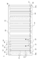
図1は、本発明の第1実施形態におけるエアマット1の斜視図である。
FIG. 1 is a perspective view of an
エアマット1は、ベースマット層3と、該ベースマット層3上に積層される2つのエアマット層(下段エアマット層5、上段エアマット層7)とを備えている。ベースマット層3と下段エアマット層5とは一体に形成され、上段エアマット層7は、ベースマット層3及び下段エアマット層5とは独立して形成されている。
The
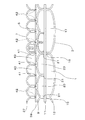
図2は、図1のII−II線断面図である。 2 is a cross-sectional view taken along line II-II in FIG.
ベースマット層3及び下段エアマット層5は、可とう性を有する第1シート9、中間シート11及び第2シート13が重ね合わされることで形成されており、第1シート9が中間シート11の上面側に、第2シート13が中間シート11の下面側に位置している。
The
15は、中間シート11と第2シート13との接合部(以下、第1接合部)を示している。隣接する第1接合部15間にエアマット1の幅方向に延びる可とう性中空第1エアセル17が複数形成され、該第1エアセル17がエアマット1の長手方向に並列することでベースマット層3が構成されている。
図3は、ベースマット層3の内部を示す平面図であり、中間シート11側から第2シート13側を視た状態を示している。
FIG. 3 is a plan view showing the inside of the
ベースマット層3では、第1接合部15の両端が開放されることで第1空気通路19が形成されており、この第1空気通路19により全ての第1エアセル17は連通している。また、第2シート13には、第1エアセル17に空気を供給するための連結口20が設けられている。
In the
次に下段エアマット層5の詳細構造を説明する。図2に示すように、21は、第1シート9と中間シート11との接合部(以下、第2接合部)を示している。隣接する第2接合部21間にエアマット1の幅方向に延びる可とう性中空第2エアセル23が複数形成され、該第2エアセル23がエアマット1の長手方向に並列することによって下段エアマット層5が構成されている。第2エアセル23の幅は、第1エアセル17の幅の2分の1に設定されており、1つの第1エアセル17の上に2つの第2エアセル23が形成されている。
Next, the detailed structure of the lower
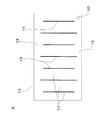
図4は、下段エアマット層5の内部を示す平面図であり、第1シート9側から中間シート11側を視た状態を示している。図2及び図4に示すように、第2エアセル23は、第2接合部21を介して交互に位置する2つのグループ25,27に分けられると共に、第2及び第3空気通路29,31によってグループ25,27ごとに連通し、中間シート11には各グループ25,27に属する第2エアセル23に空気を供給するための連結口33,35がそれぞれ設けられている。
FIG. 4 is a plan view showing the inside of the lower
次に上段エアマット層7の詳細構造を説明する。図2に示すように、上段エアマット層7は、可とう性を有する第3及び第4シート37,39が重ね合わされてなり、第3シート37は上段エアマット層7の上面側に、第4シート39は上段エアマット層7の下面側に位置している。
Next, the detailed structure of the upper
41は、第3シート37と第4シート39との接合部(以下、第3接合部)を示している。隣接する第3接合部41間にエアマット1の幅方向に延びる可とう性中空第3エアセル43が複数形成され、該第3エアセル43がエアマット1の長手方向に並列することで上段エアマット層7が構成されている。第3エアセル43の幅は、第2エアセル23の幅の2分の1に設定されており、1つの第2エアセル23の上に2つの第3エアセル43があるように上段エアマット層7は下段エアマット層5上に配置されている。また、隣接する2つの第3エアセル43の間には、いずれの箇所においても、第3シート37と第4シート39とを貫通するスリット42が形成されている。スリット42は、エアマット1の幅方向(第3接合部41に沿う方向)に延びるものであって、その長さはエアマット1の両端部を除くエアマット1の幅略全体に亘っている。
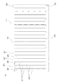
図5は、上段エアマット層7の内部を示す平面図であり、第3シート37側から第4シート39側を視た状態を示している。図2及び図5に示すように、第3エアセル43は、第3接合部41を介して交互に位置する2つのグループ45,47に分けられると共に、第4及び第5空気通路49,51によってグループ45,47ごとに連通している。第4シート39には、各グループ45,47に属する第3エアセル43に空気を供給するための連結口53,55がそれぞれ設けられている。
FIG. 5 is a plan view showing the inside of the upper
また、エアマット1では、図2に示すように、第2エアセル23を形成する第1シート9は中間シート11よりも長くなっている。これらのシートが第2接合部21でエアマット1の長手方向に間隔をおいて接合された結果、第2エアセル23の断面では、下方に位置する中間シート11で形成された下面部57よりも、上方に位置する第1シート9で形成された上面部59が長くなっている。
In the
また、第3エアセル43を形成する第3シート37は第4シート39よりも長くなっている。これらのシートが第3接合部41でエアマット1の長手方向に間隔をおいて接合された結果、第3エアセル43の断面では、第4シート39で形成された下面部57よりも、第3シート37で形成された上面部59が長くなっている。
The
以上の構成を有するエアマット1が使用される際には、図1に示すように、連結口20,33,35,53,55には、一端がエアポンプ61に接続されたチューブ63,65,67,69,71の他端が接続される。そして、介護者や看護者等のスイッチ操作によってエアポンプ61が作動すると、第1エアセル17にはチューブ63を通過した空気が供給されて、ベースマット層3は、第1エアセル17の内部が所定の空気圧に保たれることで、弾性を有すると共に所定厚さに調整される。また、下段エアマット層5では、チューブ65,67を通じてグループ25,27(図4参照)ごとに適当な時間間隔をもって給排気がなされる。また、上段エアマット層7では、チューブ69,71を通じてグループ45,47(図5参照)ごとに適当な時間間隔をもって給排気がなされる。これにより、エアマット層5,7は、グループごと(下段エアマット層5ではグループ25,27ごと,上段エアマット層7ではグループ45,47ごと)に膨張と収縮とが行われる。なお、各エアセル17,23,43の排気については、通常に知られている方法であり、各チューブ63,65,67,69,71とエアポンプ61との接続を中断して、大気に解放することで行われるものであり、詳細な説明は省略する。なお、エアポンプ61を逆回転して排気するようにしても良い。
When the
本実施形態によれば、以上のようにエアマット1が使用されることで、下段エアマット層5の膨張・収縮と上段エアマット層7の膨張・収縮との様々な組み合わせによって、エアマット1における緻密な空気圧分布の調整が可能となり、この結果、患者の体は異なる部位ごと又は異なる身体状態ごとに押圧、開放されるため、床擦れが確実に防止される。特に、下段エアマット層5の第2エアセル23の上に、上段エアマット層7の第3エアセル43が2つ位置するように設計されていることから、患者に応じた緻密な空気圧分布の調整を行うことができ、床擦れを確実に防止することができる。また、ベースマット層3が常時膨張し続けてエアマット層5,7を支持するため、ベースマット層3の厚みが適切に調節されることで、患者の体重が局所的にエアマット1に負荷されても底着きの発生が防止される。
According to the present embodiment, by using the
また、最上層のエアマット層(すなわち上段エアマット層7)とベースマット層3との間に他のエアマット層(すなわち下段エアマット層5)が配置されていることから、図2に示した第1エアセル17の空気圧が高くベースマット層3の感触が硬くなっている場合でも、該ベースマット層3の硬い感触が患者に伝わることが抑えられる。これにより、良好な寝心地が得られる。
Further, since another air mat layer (ie, lower air mat layer 5) is disposed between the uppermost air mat layer (ie, upper air mat layer 7) and
また、下段エアマット層5がグループ25,27ごとに膨張及び収縮し、上段エアマット層7もグループ45,47ごとに膨張及び収縮するので、これらの膨張・収縮の組み合わせにより、上段エアマット層7の表面にバリエーション豊かな凹凸を形成することができる。これにより、エアマット1は、患者の身体状況や姿勢等に適したエアマットとして機能する。
Further, since the lower
また、第2エアセル23が第1エアセル17の2分の1の幅を有し、第3エアセル43が第2エアセル23の2分の1の幅を有していることから、エアマット1では上側のエアセルは下側のエアセルよりも幅が小さくなっている。これにより、患者が接する上段エアマット層7では第3エアセル43の間隔が密になることから、上段エアマット層7の膨張・収縮と下段エアマット層5の膨張・収縮との組み合わせ方が多くなり、エアマット1の表面に更に緻密な凹凸を作り出すことができる。また、患者に接する上段エアマット層7の第3エアセル43の幅が小さくなることで、患者に接触する部分を微細な面積で圧力調整することができるので、寝心地を大幅に良くすることができる。
Further, since the
また、図2に示したように、第2エアセル23の断面では、下面部57よりも上面部59が長くなっていることから、第2エアセル23が第3エアセル43下面に接する面積が多くなる。また、第3エアセル43の断面においても、下面部57よりも上面部59が長くなっていることから、第3エアセル43が患者に接する面積が多くなる。この結果、第2及び第3エアセル23,43内のエアが排気される際に、患者の自重により第2及び第3エアセル23,43を大きく収縮させることができるため、上段エアマット層7を大きく収縮させることができる。
As shown in FIG. 2, in the cross section of the
また、上段エアマット層7の第3エアセル43間の全箇所にスリット42が形成されていることで、エアマット1に患者の自重が負荷された際に、各第3エアセル43の移動量を大きく確保することができる。これにより、エアマット1の表面を利用者の身体状況に適した凹凸の状態にすることに有利になる。
In addition, since
次に本発明の第2実施形態について説明する。なお、第2実施形態では、エアマット層5,7に係る構成が第1実施形態とは異なっており、以下の説明では、この相違点を中心に説明する。 Next, a second embodiment of the present invention will be described. In the second embodiment, the configuration relating to the air mat layers 5 and 7 is different from that of the first embodiment. In the following description, this difference will be mainly described.
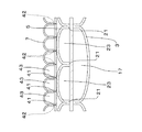
図6は、第2実施形態におけるエアマット1の図2対応断面図である。第2実施形態では、上段エアマット層7の第3エアセル43の幅は、下段エアマット層5の第2エアセル23の幅の3分の1に設定されており、1つの第2エアセル23の上に3つの第3エアセル43がある。
FIG. 6 is a cross-sectional view corresponding to FIG. 2 of the
図7は、第2実施形態における上段エアマット層7の内部を示す平面図であり、図8は、図7のVIII−VIII線断面図である。
FIG. 7 is a plan view showing the inside of the upper
上段エアマット層7において、第3エアセル43は第3接合部41によって3つのグループ91,92,93に分けられており、グループ91,93の第3エアセル43は、それぞれ、第6及び第7空気通路94,95によって連通している。第4シート39には各グループ91,92,93に空気を供給するための連結口96,97,98がそれぞれ設けられている。99は、連結口97に一端99aが接続されたブリッジパイプを示している。ブリッジパイプ99は、前記一端99aからエアマット1の長手方向に延びて、他端99bが、グループ92に属する第3エアセル43のうち連結口97から最も離れた第3エアセル43内に位置しており、前記一端99aから他端99bに至る途中に存在する第3接合部41を貫通している。ブリッジパイプ99では、グループ92の各第3エアセル43内を通過する部分に孔87が形成されており、ブリッジパイプ99を介してグループ92の第3エアセル43は連通している。また、図8に示すように、ブリッジパイプ99が第3接合部41を貫通する箇所にはシール89が施されており、このシール89により、グループ91,92,93の第3エアセル43は、他のグループの第3エアセル43と連通しないようになっている。
In the upper
上記構成を有する第2実施形態のエアマット1が使用される際には、連結口20,33,35(図1、図3、図4参照),96,97,98には、一端がエアポンプ61に接続されたチューブの他端が接続される。そして、エアポンプ61の作動により、ベースマット層3の第1エアセル17は、第1実施形態と同様に常に膨張した状態に保たれる一方で、エアマット層5,7では、チューブからグループごと(下段エアマット層5ではグループ25,27ごと、上段エアマット層7ではグループ91,92,93ごと)に適当な時間間隔をもって給排気がなされる。これにより、エアマット層5,7は、前記グループごとに膨張と収縮とを繰り返す。
When the
本実施形態におけるエアマット1によれば、第1実施形態に比して、上段エアマット層7の第3エアセル43はより多くのグループに分けられて、そのグループごとに膨張と収縮を行うようになっていることから、エアセルの空気圧を患者に適したものにすることができると共に、患者が接する上段エアマット層7の表面に更にバリエーション豊かな凹凸を形成することができる。これにより、患者の床擦れを防止することができると共に、上段エアマット層7の表面を患者の身体状況に適した凹凸の状態にする上で一層有利になる。
According to the
次に本発明の第3実施形態について説明する。なお、第3実施形態では、下段エアマット層5に係る構成が第1実施形態とは異なっており、以下の説明では、この相違点を中心に説明する。なお、本実施形態では、第1実施形態と同様に、下段エアマット層5の1つの第2エアセル23の上に上段エアマット層7の2つの第3エアセルがあり、第3エアセル43は、2つのグループに分けられて、グループごとに連通している。
Next, a third embodiment of the present invention will be described. In the third embodiment, the configuration related to the lower
図9は、第3実施形態における下段エアマット層5の内部を示す平面図である。
FIG. 9 is a plan view showing the inside of the lower
下段エアマット層5の第2エアセル23は、第2接合部21によって3つのグループ73,75,77に分けられて、グループ73,77の第2エアセル23は、それぞれ、第8及び第9空気通路82,84によって連通している。第2シート11には、グループ73,75,77に空気を供給するための連結口79,81,83が設けられている。グループ75の第2エアセル23は、第2実施形態におけるグループ92の第3エアセル43と同様に(図7参照)、連結口81に接続されたブリッジパイプ85を介して連通している。
The
上記構成を有する第3実施形態のエアマット1が使用される際には、連結口20,53,55(図1、図3、図5参照),79,81,83には、一端がエアポンプ61に接続されたチューブの他端が接続される。そして、エアポンプ61の作動により、ベースマット層3の第1エアセル17は、第1実施形態と同様に常に膨張した状態に保たれる一方で、エアマット層5,7では、チューブからグループごと(下段エアマット層5ではグループ73,75,77ごと、上段エアマット層7ではグループ45,47ごと)に適当な時間間隔をもって給排気がなされる。これにより、エアマット層5,7は、前記グループごとに膨張と収縮とを繰り返す。
When the
本実施形態におけるエアマット1によれば、第1実施形態に比して、下段エアマット層5の第2エアセル23はより多くのグループに分けられて、そのグループごとに膨張と収縮を行うようになることから、エアセルの空気圧を患者に適したものにすることができると共に、患者が接する上段エアマット層7の表面に更にバリエーション豊かな凹凸を形成することができる。これにより、患者の床擦れを防止することができると共に、前記上段エアマット層7の表面を患者の身体状況に適した凹凸の状態にする上で一層有利になる。
According to the
本発明は、上述した実施形態のみに限定されるものではなく、特許請求の範囲内において、種々改変することができる。 The present invention is not limited to the above-described embodiments, and various modifications can be made within the scope of the claims.
例えば、下段エアマット層5とベースマット層3とは、独立して形成されても良い。この場合、下段エアマット層5とベースマット層3とは、それぞれ2つのシートを重ね合わせた状態で上述した第1及び第2接合部15,21に対応する接合部を形成することで構成される。また、下段エアマット層5と上段エアマット層7とを一体に成形し、これらをベースマット層3と別体或いはベースマット層3とも一体に形成しても良い。
For example, the lower
また、スリット42は、第3エアセル43間の全箇所に形成されずに、例えば、体重が良くかかる中央部分等のように、所定位置における第3エアセル43間のみに形成されても良い。また、所定間隔ごとにスリット42を設けても良い。
Further, the
また、スリット42は、エアマット1の幅略全体に亘るような長いものではなく、エアマット1の中央のみに形成される短いものであっても良い。このようにスリット42の形成位置や長さが調整されることで、床擦れの生じやすい背中などが載る部分のエアマット1表面を利用者の身体状況に適した凹凸状態にしながら、エアマット1の強度を確保することができる。
Further, the
また、上段エアマット層7と下段エアマット層5とのいずれもが独立して形成されるような場合には、スリット42は、上段エアマット層7と下段エアマット層5とのいずれにも形成されても良く、或いは上段エアマット層7と下段エアマット層5とのいずれか一方のみに形成されても良い。
In addition, when both the upper
また、ベースマット層3に積層されるエアマット層の数は、上述のように上段エアマット層7及び下段エアマット層5の2つに限られない。例えば、図1、図2に示した上段エアマット層7のごとく下段エアマット層5と独立して形成された上段エアマット層7を複数個設けて、下部エアマット層5の上に順次配置していくことで、任意の数のエアマット層をベースマット層3に積層するようにしても良い。
Further, the number of air mat layers laminated on the
また、第1及び第2実施形態では、上段エアマット層7の第3エアセル43を下段エアマット層5の1つの第2エアセル23の上に2つ或いは3つ設けたものであるが、下段エアマット層5の1つのエアセル23の上に設置される上段エアマット層7のエアセル43の数は、これらの数に限られるものではなく、上段エアマット層7のエアセル43の数を下段エアマット層5のエアセル23の数よりも多くしたり、或いは下段エアマット層5のエアセル23と同じ数にしても良い。また、下段エアマット層5の1つのエアセル23の上に上段エアマット層7のエアセル43の2.5コ分が積層されて、残りの0.5コ分は隣接する下段エアマット層5のエアセル23の上に積層されるようにしても良い。
In the first and second embodiments, two or three
また、第1実施形態においては、上段エアマット層7の第3エアセル43を2つのグループに分けたが、このグループ数に限られるものではなく、例えば、3つや4つの多グループに分けて、各グループに供給するエアの給排気を調整するようにしても良い。同様に、下段エアマット層5の第2エアセル23も3つや4つのグループに分けて、各グループへのエアの給排気を調整するようにしても良い。
In the first embodiment, the
また、前述の実施形態では、下段エアマット層5の第2エアセル23及び上段エアマット層7の第3エアセル43を、それぞれグループ別に膨張・収縮させているが、本発明においても可変エアセルを1段として使用したい場合には、下段エアマット層5の第2エアセル23或いは上段エアマット層7の第3エアセル43内の空気を排気することで、対応することもできる。例えば、周囲の環境によって、エアマット層の高さを高くできない場合等では、下段エアマット層5の第2エアセル23或いは上段エアマット層7の第3エアセル43の一方に空気を入れないようにして、低い高さのエアマット層とすることも出きる。或いは、下段エアマット層5の第2エアセル23に供給するエア圧を半分位に少なくして、エアマット1の高さを低く抑えるようにしても良い。また、この場合においても、上段エアマット層7については、グループごとに空気を供給・排気してグループごとに膨張・収縮を行わせることで、床擦れの防止が図られる。また、下段エアマット層5の下には、常時膨張した状態にあるベースマット層3が配置されていることから、底着きの発生も防止することができる。
Further, in the above-described embodiment, the
また、上述の実施形態では、下段エアマット層5の第2エアセル23と上段エアマット層7の第3エアセル43とは、ベッドの長手方向に同じ形状、大きさで設けられているが、頭部、背中、臀部、脚部などの部位に応じて、下段エアマット層5の第2エアセル23と上段エアマット層7の第3エアセル43の大きさや数量を変えるようにしても良い。例えば、床擦れが生じやすい部位のみ上段エアマット層7の第3エアセル43を多くし、他の部位は上段エアセルを少なくするようにしても良い。
In the above-described embodiment, the
また、ベースエアマット層3は、エアセルによって構成されるものに限られず、例えばゴムやウレタンなどの弾性を有する材料により形成されたものでも良い。このようなベースマット層3を使用する場合でも、ベースマット層3が適切な厚みに形成されることで、底着きの発生は防止される。
Further, the base
また、ベースマット層3は省略されても良い。この場合においても、下段エアマット層5が常時所定以上の厚さを有するように下段エアマット層5の第2エアセル23に空気が供給・排気されることで、底着きの発生は防止される。
Further, the
Claims (6)
前記複数段のエアマット層の各層は、前記エアマットの幅方向に延びる可とう性中空エアセルが、前記エアマットの長手方向に並列することによって構成され、
前記複数段のエアマット層の上段エアマット層及び下段エアマット層の各層における該エアセルは、複数のグループに分けられて、グループごとに適当な時間間隔をもって空気が供給・排気されることで、グループごとに膨張・収縮を繰り返すようになっており、
前記上段エアマット層と前記下段エアマット層との少なくとも一方において、所定位置で隣接する2つのエアセルの間には、前記エアマットの幅方向に延びるスリットが形成されていることを特徴とするエアマット。 In an air mat comprising a plurality of air mat layers stacked in the vertical direction,
Each layer of the air mat layers of the plurality of stages is configured by flexible hollow air cells extending in the width direction of the air mat arranged in parallel in the longitudinal direction of the air mat,
The air cells in each of the upper air mat layer and the lower air mat layer of the plurality of air mat layers are divided into a plurality of groups, and air is supplied and exhausted at appropriate time intervals for each group. It is designed to repeat expansion and contraction ,
In at least one of the upper air mat layer and the lower air mat layer, a slit extending in the width direction of the air mat is formed between two air cells adjacent at a predetermined position .
前記エアマット層は、前記ベースマット層の上に積層されることを特徴とする請求項1に記載のエアマット。 A base mat layer having elasticity and adjusted to a predetermined thickness;
The air mat according to claim 1, wherein the air mat layer is laminated on the base mat layer.
Priority Applications (1)
| Application Number | Priority Date | Filing Date | Title |
|---|---|---|---|
| JP2009544561A JP5331007B2 (en) | 2007-12-03 | 2008-11-26 | Air mat |
Applications Claiming Priority (4)
| Application Number | Priority Date | Filing Date | Title |
|---|---|---|---|
| JP2007312450 | 2007-12-03 | ||
| JP2007312450 | 2007-12-03 | ||
| PCT/JP2008/003478 WO2009072253A1 (en) | 2007-12-03 | 2008-11-26 | Air mattress |
| JP2009544561A JP5331007B2 (en) | 2007-12-03 | 2008-11-26 | Air mat |
Publications (2)
| Publication Number | Publication Date |
|---|---|
| JPWO2009072253A1 JPWO2009072253A1 (en) | 2011-04-21 |
| JP5331007B2 true JP5331007B2 (en) | 2013-10-30 |
Family
ID=40717436
Family Applications (1)
| Application Number | Title | Priority Date | Filing Date |
|---|---|---|---|
| JP2009544561A Expired - Fee Related JP5331007B2 (en) | 2007-12-03 | 2008-11-26 | Air mat |
Country Status (6)
| Country | Link |
|---|---|
| US (1) | US8127386B2 (en) |
| JP (1) | JP5331007B2 (en) |
| KR (1) | KR101503099B1 (en) |
| CN (1) | CN101883550B (en) |
| TW (1) | TWI414285B (en) |
| WO (1) | WO2009072253A1 (en) |
Families Citing this family (31)
| Publication number | Priority date | Publication date | Assignee | Title |
|---|---|---|---|---|
| FR2949321B1 (en) * | 2009-08-31 | 2011-09-16 | Hill Rom Ind Sa | SUPPORT DEVICE COMPRISING A MATTRESS OF ADJUSTABLE DIMENSIONS USING INFLATABLE CELLS |
| JP5558130B2 (en) | 2010-02-05 | 2014-07-23 | パラマウントベッド株式会社 | Air mattress with built-in pump |
| JP5468928B2 (en) * | 2010-02-05 | 2014-04-09 | パラマウントベッド株式会社 | Air mattress |
| US20110252571A1 (en) * | 2010-04-15 | 2011-10-20 | Liu Tsung Hsi | Multiple air passages applied to air mattress |
| EP2575723B1 (en) | 2010-06-02 | 2014-12-31 | TouchSensor Technologies, LLC | Therapeutic support device allowing capillary blood flow |
| JP5592724B2 (en) * | 2010-07-30 | 2014-09-17 | 株式会社モルテン | Air mat device |
| WO2012030829A2 (en) * | 2010-09-01 | 2012-03-08 | Kci Licensing, Inc. | Patient support apparatuses and methods |
| ES2625803T3 (en) | 2010-10-05 | 2017-07-20 | Touchsensor Technologies, Llc | Support surface cover with selectively inflatable cells |
| CN101999978B (en) * | 2010-12-02 | 2014-03-26 | 无锡尚瑞德医疗器械有限公司 | Double-layer pulse air circulation bedsore-preventing cushion |
| KR101213400B1 (en) | 2011-12-05 | 2012-12-21 | 주식회사 세라젬셀루피딕 | Method and apparatus for controlling pressure of mattress |
| JP5555738B2 (en) * | 2012-04-11 | 2014-07-23 | フランスベッド株式会社 | Mattress equipment |
| MX359745B (en) * | 2012-08-21 | 2018-10-09 | Huntleigh Technology Ltd | Patient transport device. |
| JP6091113B2 (en) * | 2012-08-31 | 2017-03-08 | 株式会社モルテン | Air mattress |
| KR101402377B1 (en) | 2012-10-04 | 2014-06-03 | 주식회사 세라젬셀루피딕 | Mattress and method for controlling pressure of mattress |
| CN103784284A (en) * | 2012-10-29 | 2014-05-14 | 陈鼎然 | Air pressure regulating method of air bed controller |
| KR101529133B1 (en) * | 2013-08-27 | 2015-06-16 | 함의신 | Three dimensions bellows welding method and the welding device and the bellows |
| WO2015162667A1 (en) * | 2014-04-21 | 2015-10-29 | 株式会社 ハイビックス | Cells for air mattress, and air mattress |
| JP6284499B2 (en) * | 2014-05-28 | 2018-02-28 | 株式会社タイカ | Fluid-filled rug |
| MX2017003041A (en) * | 2014-09-08 | 2017-10-18 | Idéen ApS | Inflatable air cushion with pressure indicator. |
| KR101681468B1 (en) * | 2015-09-22 | 2016-12-02 | 전북대학교병원 | Air mattress for serious patient |
| CN106551764A (en) * | 2015-09-24 | 2017-04-05 | 唐德工业股份有限公司 | The intracapsular gas transmission structure of multilamellar air fluidized bed |
| KR20170065856A (en) * | 2015-12-04 | 2017-06-14 | 휴먼플러스(주) | System and method for providing health care service utilizing smart air mattress |
| KR101945693B1 (en) * | 2016-12-08 | 2019-02-08 | 주식회사 아임삭 | Water cooling mattress |
| KR101876500B1 (en) * | 2017-03-07 | 2018-07-10 | 박재윤 | Air mattress for medical diagnosis device |
| US10070732B1 (en) | 2017-03-09 | 2018-09-11 | Tangtring Seating Technology Inc. | Air bag module of inflatable mattress |
| JPWO2019031271A1 (en) * | 2017-08-11 | 2020-07-09 | 住友理工株式会社 | Fluid cell mattress |
| WO2020081908A1 (en) * | 2018-10-18 | 2020-04-23 | Unisoft Medical Corporation | Cell bladder, expandable bladder, port system and attachment system |
| CN109124162B (en) * | 2018-11-16 | 2021-06-04 | 深圳市联奕实业有限公司 | Hardness adjustable mattress |
| KR102235062B1 (en) * | 2019-09-17 | 2021-04-01 | 주식회사 영화의료기 | Active body pressure dispersion-typed air cell mattress |
| US11344461B2 (en) * | 2020-07-17 | 2022-05-31 | Toyota Motor Engineering & Manufacturing North America, Inc. | Support cushion liners comprising artificial muscles |
| KR102621414B1 (en) * | 2021-06-24 | 2024-01-05 | 정한상 | Mattress for prevention of decubitus to have the heating function |
Citations (9)
| Publication number | Priority date | Publication date | Assignee | Title |
|---|---|---|---|---|
| JPH03244457A (en) * | 1990-02-23 | 1991-10-31 | Matsushita Electric Works Ltd | Air mat |
| JPH06335501A (en) * | 1993-05-27 | 1994-12-06 | Tokyo Electric Co Ltd | Air mat device |
| JPH0898860A (en) * | 1994-09-30 | 1996-04-16 | Okamoto Ind Inc | Bedsore preventing mat |
| JPH08117294A (en) * | 1994-10-25 | 1996-05-14 | Okamoto Ind Inc | Bedsore prevention mat |
| JPH09140510A (en) * | 1995-11-27 | 1997-06-03 | France Bed Co Ltd | Mattress device |
| JP2002065405A (en) * | 2000-08-28 | 2002-03-05 | Molten Corp | Air mat |
| JP2004081245A (en) * | 2002-08-22 | 2004-03-18 | Sanwa Kaken Kogyo Kk | Air mattress |
| JP3115039U (en) * | 2005-07-22 | 2005-11-04 | 株式会社ケープ | Air mattress |
| WO2007023676A1 (en) * | 2005-08-25 | 2007-03-01 | Molten Corporation | Air mattress |
Family Cites Families (12)
| Publication number | Priority date | Publication date | Assignee | Title |
|---|---|---|---|---|
| JPH03115039A (en) | 1989-09-29 | 1991-05-16 | Konica Corp | Paper feed sensor |
| JPH03115039U (en) * | 1990-02-28 | 1991-11-27 | ||
| US5243723A (en) * | 1992-03-23 | 1993-09-14 | Innovative Medical Systems, Inc. | Multi-chambered sequentially pressurized air mattress with four layers |
| JPH08164169A (en) | 1994-12-13 | 1996-06-25 | Keepu:Kk | Air mat for medical treatment |
| US5890245A (en) * | 1996-11-05 | 1999-04-06 | Therapy Concepts, Inc. | Disposable ventilating mattress and method of making same |
| DE29712428U1 (en) * | 1997-07-14 | 1997-09-11 | APEX MEDICAL Corp., Taipeh/T'ai-pei | Air mattress with changeable ascent and descent effects |
| JP3290159B2 (en) * | 1998-06-03 | 2002-06-10 | 株式会社モルテン | Air mat |
| CH693299A5 (en) * | 1999-07-15 | 2003-05-30 | Doc Ag | Cushion, in particular mattress. |
| US6855158B2 (en) * | 2001-09-11 | 2005-02-15 | Hill-Rom Services, Inc. | Thermo-regulating patient support structure |
| US20040107503A1 (en) * | 2002-12-09 | 2004-06-10 | Eezcare Medical Corp. | Inflation body structure for an air mattress |
| TWI279228B (en) * | 2003-06-18 | 2007-04-21 | Tsung-Hsi Liu | Width-adjustable air mattress bed structure |
| CN2694837Y (en) * | 2004-04-16 | 2005-04-27 | 巫新财 | Multi-chamber air bed |
-
2008
- 2008-11-26 CN CN200880118880.5A patent/CN101883550B/en not_active Expired - Fee Related
- 2008-11-26 WO PCT/JP2008/003478 patent/WO2009072253A1/en active Application Filing
- 2008-11-26 US US12/743,382 patent/US8127386B2/en not_active Expired - Fee Related
- 2008-11-26 JP JP2009544561A patent/JP5331007B2/en not_active Expired - Fee Related
- 2008-11-26 KR KR1020107011756A patent/KR101503099B1/en active IP Right Grant
- 2008-12-02 TW TW097146829A patent/TWI414285B/en not_active IP Right Cessation
Patent Citations (9)
| Publication number | Priority date | Publication date | Assignee | Title |
|---|---|---|---|---|
| JPH03244457A (en) * | 1990-02-23 | 1991-10-31 | Matsushita Electric Works Ltd | Air mat |
| JPH06335501A (en) * | 1993-05-27 | 1994-12-06 | Tokyo Electric Co Ltd | Air mat device |
| JPH0898860A (en) * | 1994-09-30 | 1996-04-16 | Okamoto Ind Inc | Bedsore preventing mat |
| JPH08117294A (en) * | 1994-10-25 | 1996-05-14 | Okamoto Ind Inc | Bedsore prevention mat |
| JPH09140510A (en) * | 1995-11-27 | 1997-06-03 | France Bed Co Ltd | Mattress device |
| JP2002065405A (en) * | 2000-08-28 | 2002-03-05 | Molten Corp | Air mat |
| JP2004081245A (en) * | 2002-08-22 | 2004-03-18 | Sanwa Kaken Kogyo Kk | Air mattress |
| JP3115039U (en) * | 2005-07-22 | 2005-11-04 | 株式会社ケープ | Air mattress |
| WO2007023676A1 (en) * | 2005-08-25 | 2007-03-01 | Molten Corporation | Air mattress |
Also Published As
| Publication number | Publication date |
|---|---|
| WO2009072253A1 (en) | 2009-06-11 |
| JPWO2009072253A1 (en) | 2011-04-21 |
| KR101503099B1 (en) | 2015-03-16 |
| US20100263131A1 (en) | 2010-10-21 |
| TWI414285B (en) | 2013-11-11 |
| US8127386B2 (en) | 2012-03-06 |
| CN101883550B (en) | 2014-06-11 |
| CN101883550A (en) | 2010-11-10 |
| KR20100090784A (en) | 2010-08-17 |
| TW200940043A (en) | 2009-10-01 |
Similar Documents
| Publication | Publication Date | Title |
|---|---|---|
| JP5331007B2 (en) | Air mat | |
| US8635726B2 (en) | Cushion bladder with middle layer having gaps and various positioned interior welds | |
| EP2758019B1 (en) | Patient/invalid support | |
| JP2014516737A5 (en) | ||
| JP5339873B2 (en) | Air mat | |
| CN105744864A (en) | Inflatable mattress | |
| US9205011B2 (en) | Pneumatic mattress | |
| WO2006023533A2 (en) | Inflatable cushion systems and method of manufacture thereof | |
| JP6670667B2 (en) | Air mattress and air mattress device | |
| JP2008543351A (en) | Inflatable parts for alternating pressure mattress | |
| JP5618695B2 (en) | Air cell and air mat provided with the same | |
| JPH08164167A (en) | Air mat for medical treatment | |
| JP6605128B2 (en) | Multilayer cushion and mattress with the same | |
| JP2008307249A (en) | Control method of air mat and air mat using control method | |
| JPH0585183B2 (en) | ||
| JP4488389B2 (en) | Bed slip prevention mat | |
| JP2017060599A (en) | Air cushion sheet and sheet | |
| JP7355679B2 (en) | Fluid cell for body pressure support | |
| WO2008030940A2 (en) | Multi-zone coil construction airbed | |
| JP6967375B2 (en) | Air mat device | |
| JPH054822Y2 (en) | ||
| JP5785928B2 (en) | Bedding mat | |
| CN115175827A (en) | Airbag device for seat and method for manufacturing same | |
| JPH08164166A (en) | Air mat for medical treatment | |
| WO2007030615A1 (en) | Multi-zone coil construction airbed |
Legal Events
| Date | Code | Title | Description |
|---|---|---|---|
| A621 | Written request for application examination |
Free format text: JAPANESE INTERMEDIATE CODE: A621 Effective date: 20111117 |
|
| RD02 | Notification of acceptance of power of attorney |
Free format text: JAPANESE INTERMEDIATE CODE: A7422 Effective date: 20121213 |
|
| A131 | Notification of reasons for refusal |
Free format text: JAPANESE INTERMEDIATE CODE: A131 Effective date: 20130115 |
|
| A521 | Request for written amendment filed |
Free format text: JAPANESE INTERMEDIATE CODE: A523 Effective date: 20130306 |
|
| A131 | Notification of reasons for refusal |
Free format text: JAPANESE INTERMEDIATE CODE: A131 Effective date: 20130409 |
|
| A521 | Request for written amendment filed |
Free format text: JAPANESE INTERMEDIATE CODE: A523 Effective date: 20130610 |
|
| TRDD | Decision of grant or rejection written | ||
| A01 | Written decision to grant a patent or to grant a registration (utility model) |
Free format text: JAPANESE INTERMEDIATE CODE: A01 Effective date: 20130702 |
|
| A61 | First payment of annual fees (during grant procedure) |
Free format text: JAPANESE INTERMEDIATE CODE: A61 Effective date: 20130726 |
|
| R150 | Certificate of patent or registration of utility model |
Ref document number: 5331007 Country of ref document: JP Free format text: JAPANESE INTERMEDIATE CODE: R150 Free format text: JAPANESE INTERMEDIATE CODE: R150 |
|
| R250 | Receipt of annual fees |
Free format text: JAPANESE INTERMEDIATE CODE: R250 |
|
| R250 | Receipt of annual fees |
Free format text: JAPANESE INTERMEDIATE CODE: R250 |
|
| R250 | Receipt of annual fees |
Free format text: JAPANESE INTERMEDIATE CODE: R250 |
|
| R250 | Receipt of annual fees |
Free format text: JAPANESE INTERMEDIATE CODE: R250 |
|
| R250 | Receipt of annual fees |
Free format text: JAPANESE INTERMEDIATE CODE: R250 |
|
| R250 | Receipt of annual fees |
Free format text: JAPANESE INTERMEDIATE CODE: R250 |
|
| LAPS | Cancellation because of no payment of annual fees |