JP2017205154A - Fluid cell-type mattress - Google Patents
Fluid cell-type mattress Download PDFInfo
- Publication number
- JP2017205154A JP2017205154A JP2016097861A JP2016097861A JP2017205154A JP 2017205154 A JP2017205154 A JP 2017205154A JP 2016097861 A JP2016097861 A JP 2016097861A JP 2016097861 A JP2016097861 A JP 2016097861A JP 2017205154 A JP2017205154 A JP 2017205154A
- Authority
- JP
- Japan
- Prior art keywords
- fluid
- cell
- sheet
- support
- communication
- Prior art date
- Legal status (The legal status is an assumption and is not a legal conclusion. Google has not performed a legal analysis and makes no representation as to the accuracy of the status listed.)
- Pending
Links
Images


Abstract
Description
本発明は、ベッドの上面に敷かれて使用者を載せる支持面を構成するマットレスであって、特に支持面の少なくとも一部が内部に流体室を備える伸縮可能な流体セルによって構成された流体セル式マットレスに関するものである。 The present invention relates to a mattress that constitutes a support surface that is laid on the upper surface of a bed and on which a user is placed, and in particular, at least a part of the support surface is constituted by a stretchable fluid cell having a fluid chamber therein. It relates to a mattress.
従来から、体圧の分散化による寝心地の改善などを目的とする流体セル式マットレスが提案されている。流体セル式マットレスは、たとえば特許第4409906号公報(特許文献1)に記載された床ずれ防止マットのように、使用者を支持する支持面の一部(膨縮ゾーン)が伸縮可能とされたエアセルによって構成されている。そして、使用者が膨縮ゾーンに載って及ぼす荷重(体重)に応じてエアセルが変形することにより、使用者に作用する膨縮ゾーンの当接圧(体圧)の分散化などが図られて、寝心地の改善などが実現されるようになっている。 Conventionally, fluid cell mattresses have been proposed for the purpose of improving sleeping comfort by dispersing body pressure. A fluid cell type mattress is an air cell in which a part of a support surface (expansion / contraction zone) for supporting a user can be expanded and contracted, such as a mat for preventing bed slip described in Japanese Patent No. 4409906 (Patent Document 1). It is constituted by. Then, the air cell is deformed according to the load (weight) exerted on the expansion / contraction zone by the user, so that the contact pressure (body pressure) of the expansion / contraction zone acting on the user is dispersed. Improvement of sleeping comfort is realized.
ところで、特許文献1の床ずれ防止マットでは、膨縮ゾーンを構成する複数のエアセルが連通管によって相互に連通されているとともにポンプに連通されている。そして、エアセル間での空気の流動やポンプによるエアセル内への空気の給排によってエアセルが上下に伸縮することにより、床ずれ防止効果が発揮され得るようになっている。特許文献1の床ずれ防止マットでは、エアセルが相互に重ね合わされる上下のマット用シートによって構成されており、エアセルを相互に連通する連通管が、それら上下のマット用シートにそれぞれ形成された半筒状の連結パイプ構成部の上下開口部を相互に突き合わせることで形成されている。 By the way, in the floor slip prevention mat of Patent Document 1, a plurality of air cells constituting the expansion / contraction zone are communicated with each other by a communication pipe and communicated with a pump. The air cell expands and contracts vertically by the flow of air between the air cells and the supply and discharge of air into the air cell by a pump, so that the bed slip prevention effect can be exhibited. The floor slip prevention mat of Patent Document 1 is composed of upper and lower mat sheets in which air cells are superimposed on each other, and communication pipes that communicate the air cells with each other are formed in the upper and lower mat sheets, respectively. It is formed by mutually abutting the upper and lower openings of the connecting pipe component.
しかしながら、特許文献1の床ずれ防止マットに示された連通管は、上下のマット用シートに形成された半筒状の連結パイプ構成部の上下開口部を相互に突き合わせて形成されていることから、連結パイプ構成部の成形部分を備える成形用金型を準備してマット用シートを形成する必要がある。それ故、連通管の通路断面積や通路長を変更するためにはマット用シートの成形用金型を新規に準備する必要があって、エアセル間における連通管を通じた空気の流動特性は、容易に変更して調節することができなかった。 However, the communication pipe shown in the floor slip prevention mat of Patent Document 1 is formed by abutting the upper and lower openings of the semi-cylindrical connecting pipe components formed on the upper and lower mat sheets, It is necessary to prepare a molding die provided with a molding portion of the connecting pipe constituting portion to form a mat sheet. Therefore, in order to change the passage cross-sectional area and the passage length of the communication pipe, it is necessary to prepare a new mold for forming the mat sheet, and the air flow characteristic through the communication pipe between the air cells is easy. It was not possible to adjust to change.
さらに、半筒状の連結パイプ構成部を相互に突き合わせて所定の断面形状を有する連通管を形成するためには、連結パイプ構成部を含むマット用シートの寸法や形状に高い精度が要求されると共に、上下のマット用シートを高精度に位置決めしつつ、それらマット用シートを連結パイプ構成部の外側で相互に固着する必要があって、製造が困難であった。 Further, in order to form a communication pipe having a predetermined cross-sectional shape by abutting the semi-cylindrical connecting pipe components, high accuracy is required for the size and shape of the mat sheet including the connecting pipe components. At the same time, it is necessary to fix the upper and lower mat sheets with high precision while fixing the mat sheets to each other on the outside of the connecting pipe constituent part, which makes manufacturing difficult.
更にまた、連結パイプ構成部を突き合わせて形成された連通管は、常時開口して通路断面積が一定の連通状態とされることから、連通管を通じたエアセル間の空気の流動が、膨縮ゾーンに対する荷重の入力初期から大きく許容されて、膨縮ゾーンの表面が容易に変形する。その結果、マット上面による使用者の安定した支持がなされ難くなって、船酔い感などの不快な感覚を使用者に与えるおそれもあった。 Furthermore, since the communication pipe formed by abutting the connecting pipe components is always open and the passage cross-sectional area is in a constant communication state, the air flow between the air cells through the communication pipe is expanded and contracted. Therefore, the surface of the expansion / contraction zone is easily deformed. As a result, it is difficult for the user to stably support the mat upper surface, and there is a risk of giving the user an unpleasant feeling such as seasickness.
本発明は、上述の事情を背景に為されたものであって、その解決課題は、製造し易い簡単な構造によって、優れた体圧分散作用を発揮しつつ、不快な船酔い感などを安定した支持によって防止することも可能となる、新規な構造の流体セル式マットレスを提供することにある。 The present invention has been made in the background of the above-mentioned circumstances, and the solution is to provide an excellent body pressure dispersion function and a stable feeling of unpleasant seasickness with a simple structure that is easy to manufacture. It is an object of the present invention to provide a fluid cell type mattress having a novel structure which can be prevented by the support.
以下、このような課題を解決するために為された本発明の態様を記載する。なお、以下に記載の各態様において採用される構成要素は、可能な限り任意の組み合わせで採用可能である。 Hereinafter, the aspect of this invention made | formed in order to solve such a subject is described. In addition, the component employ | adopted in each aspect as described below is employable by arbitrary combinations as much as possible.
すなわち、本発明の第一の態様は、内部に流体室を備えて伸縮可能とされた流体セルによって、使用者を載せる支持面の少なくとも一部が構成された流体セル式マットレスであって、前記流体セルが相互に重ね合わされる上シートと下シートを含んで構成されており、それら上シートと下シートによって複数の該流体セルが一体的に形成されていると共に、それら複数の流体セルの周囲において該上シートと該下シートが相互に重ね合わされて固着されている一方、該流体セルの周囲において該上シートと該下シートが部分的に非固着で重ね合わされており、それら上シートと下シートの非固着領域の重ね合わせ面間に前記流体室を相互に連通する連通路が形成されていると共に、該上シートと該下シートの非固着領域における重ね合わせ面間の距離が該連通路内の圧力に応じて変化することで該連通路の通路断面積が可変とされていることを、特徴とする。 That is, the first aspect of the present invention is a fluid cell type mattress in which at least a part of a support surface on which a user is placed is constituted by a fluid cell that is provided with a fluid chamber inside and can be expanded and contracted. The fluid cell is configured to include an upper sheet and a lower sheet on which the fluid cells are overlapped with each other, and the plurality of fluid cells are integrally formed by the upper sheet and the lower sheet, and around the fluid cells. The upper sheet and the lower sheet are overlapped and fixed to each other on the other hand, while the upper sheet and the lower sheet are partially unfixed and stacked around the fluid cell. A communicating path is formed between the overlapping surfaces of the non-adhering regions of the sheet to communicate the fluid chambers with each other, and the overlapping surfaces in the non-adhering regions of the upper sheet and the lower sheet Distance is that the passage cross-sectional area of the communication passage by which changes according to the pressure in the communication passage is variable, and wherein.
このような第一の態様に従う構造とされた流体セル式マットレスによれば、非固着領域における上シートと下シートの重ね合わせ面間に対して、流体セルの流体室を連通する連通路が形成されていると共に、連通路の通路断面積が内圧に応じて可変とされている。それ故、例えば、支持面に対して荷重が入力されると、入力初期には連通路の通路断面積が小さく、連通路を通じた流体流動量が少ないことから、荷重が入力された流体セルの流体室内の圧力が高くなることで、良好なクッション作用(弾性的な反発力)が確保されて、使用者などの安定した支持が実現される。一方、入力によって連通路内の圧力が増大することで連通路の通路断面積が大きくなることから、連通路を通じた流体流動量が増加して、荷重が入力された流体セルの流体室内の流体が連通路を通じて他の流体セルの流体室へ流動することにより、支持面が体圧分布に応じた形状に変形して、体圧の分散化が図られる。 According to the fluid cell type mattress having the structure according to the first aspect as described above, a communication path communicating the fluid chamber of the fluid cell is formed between the overlapping surfaces of the upper sheet and the lower sheet in the non-adhering region. In addition, the passage cross-sectional area of the communication passage is variable according to the internal pressure. Therefore, for example, when a load is input to the support surface, the passage cross-sectional area of the communication path is small at the initial input, and the amount of fluid flow through the communication path is small. By increasing the pressure in the fluid chamber, a good cushion action (elastic repulsive force) is ensured, and stable support for the user or the like is realized. On the other hand, since the passage cross-sectional area of the communication path increases due to an increase in pressure in the communication path due to input, the amount of fluid flow through the communication path increases, and the fluid in the fluid chamber of the fluid cell into which the load is input Flows into the fluid chamber of another fluid cell through the communication path, whereby the support surface is deformed into a shape corresponding to the body pressure distribution, and the body pressure is dispersed.
さらに、例えば、流体セルに作用する荷重が小さい場合には、連通路の通路断面積が小さくされて、連通路を通じた流体の流動量が制限されることから、流体セルの伸縮変形による支持面の変形が抑えられて、使用者などの安定した支持が実現される。一方、流体セルに作用する荷重が大きい場合には、連通路の通路断面積が大きくなって、連通路を通じた流体の流動量が増加することから、流体セルの伸縮変形によって支持面が速やかに変形して、より効率的な体圧の分散化が図られる。 Further, for example, when the load acting on the fluid cell is small, the passage cross-sectional area of the communication path is reduced, and the amount of fluid flowing through the communication path is limited. Therefore, stable support for the user and the like is realized. On the other hand, when the load acting on the fluid cell is large, the passage cross-sectional area of the communication passage is increased, and the amount of fluid flowing through the communication passage is increased. By deforming, more efficient dispersion of body pressure is achieved.
このように、連通路の通路断面積が支持面への入力荷重に応じて可変とされていることにより、支持面の変形特性が入力荷重に応じて受動的に調節されて、より快適な寝心地などを提供することが可能になる。 As described above, the passage cross-sectional area of the communication passage is made variable in accordance with the input load on the support surface, so that the deformation characteristics of the support surface are passively adjusted in accordance with the input load, so that more comfortable sleeping is possible. Etc. can be provided.
また、連通路は、流体セルの周囲において上シートと下シートが非固着で重ね合わされた非固着領域を設けることにより形成されている。それ故、上シートと下シートを流体セル構成部分の周囲で相互に重ね合わせて固着する際に、部分的な非固着領域を設けることによって、連通路を簡単に形成することができる。しかも、上シートと下シートの非固着領域を変更することによって、上シートと下シートの成形用金型の設計変更などを要することなく、連通路における流体の流動特性などを変更することが可能とされて、要求される支持面の変形特性を簡単且つ高精度に実現することができる。 Further, the communication path is formed by providing a non-adhering region where the upper sheet and the lower sheet are non-adhered and overlapped around the fluid cell. Therefore, when the upper sheet and the lower sheet are overlapped and fixed to each other around the fluid cell component, the communication path can be easily formed by providing a partial non-adhesion region. In addition, by changing the non-adhesion area between the upper sheet and the lower sheet, it is possible to change the flow characteristics of the fluid in the communication path without changing the design of the molding die for the upper sheet and the lower sheet. Thus, the required deformation characteristics of the support surface can be realized easily and with high accuracy.
本発明の第二の態様は、第一の態様に記載された流体セル式マットレスにおいて、前記流体セルの周囲において前記上シートと前記下シートが相互に溶着されているものである。 According to a second aspect of the present invention, in the fluid cell mattress described in the first aspect, the upper sheet and the lower sheet are welded to each other around the fluid cell.
第二の態様によれば、流体セル形成部分の周囲で相互に重ね合わされた上シートと下シートの固着方法として溶着を採用することにより、接着剤の塗布などの工程が不要となって、上シートと下シートを流体セル形成部分の周囲で簡単に固着することができる。 According to the second aspect, by adopting welding as a fixing method for the upper sheet and the lower sheet that are overlapped with each other around the fluid cell forming portion, a process such as application of an adhesive is unnecessary, The sheet and the lower sheet can be easily fixed around the fluid cell forming portion.
本発明の第三の態様は、第一又は第二の態様に記載された流体セル式マットレスにおいて、前記連通路内が大気圧と等しい初期状態において前記上シートと前記下シートが前記流体セルの周囲に設けられた非固着領域で相互に当接しているものである。 According to a third aspect of the present invention, in the fluid cell type mattress described in the first or second aspect, the upper sheet and the lower sheet of the fluid cell are in an initial state in which the inside of the communication path is equal to the atmospheric pressure. They are in contact with each other in a non-adhering region provided in the periphery.
第三の態様によれば、初期状態において連通路の形成部分で上シートと下シートが当接していることにより、初期状態における連通路の形状や通路断面積が安定して、例えば支持面への荷重の入力初期において目的とする支持面の変形特性を安定して得ることができる。 According to the third aspect, since the upper sheet and the lower sheet are in contact with each other at the communication passage forming portion in the initial state, the shape of the communication passage and the passage cross-sectional area in the initial state are stabilized, for example, to the support surface. Thus, the desired deformation characteristics of the support surface can be stably obtained at the initial input of the load.
本発明の第四の態様は、第三の態様に記載された流体セル式マットレスにおいて、前記連通路内が大気圧と等しい初期状態において前記流体セルの周囲に設けられた非固着領域における前記上シートと前記下シートの当接によって該連通路が遮断されているものである。 According to a fourth aspect of the present invention, in the fluid cell type mattress described in the third aspect, the upper portion in the non-adhering region provided around the fluid cell in an initial state in which the communication path is equal to the atmospheric pressure. The communication path is blocked by the contact between the sheet and the lower sheet.
第四の態様によれば、初期状態において連通路が遮断されていることによって、例えば支持面への荷重の入力初期において連通路を通じた流体流動が阻止されていることから、流体セルの変形が制限されて、流体セルの弾性的な反発力をより有利に得ることができる。 According to the fourth aspect, since the communication path is blocked in the initial state, for example, fluid flow through the communication path is prevented at the initial stage of input of the load to the support surface, so that deformation of the fluid cell is prevented. The elastic repulsive force of the fluid cell can be obtained more advantageously by being limited.
本発明の第五の態様は、第一〜第四の何れか1つの態様に記載された流体セル式マットレスにおいて、前記流体セルの前記流体室が前記連通路によって相互に連通されていると共に、それら流体室が大気中に対して密閉されているものである。 According to a fifth aspect of the present invention, in the fluid cell type mattress described in any one of the first to fourth aspects, the fluid chambers of the fluid cell are communicated with each other by the communication path. These fluid chambers are sealed against the atmosphere.
第五の態様によれば、複数の流体セルの流体室が、大気に開放されることなく大気中への流体の排出が阻止されていると共に、連通路を通じて相互に連通されていることから、流体室内の流体が過剰に排出されることによる底付きなどの不具合を防止しながら、複数の流体セルの流体室間における連通路を通じた流体流動によって、流体セルの伸縮変形が許容されて、支持面における体圧分散が有効に実現される。 According to the fifth aspect, the fluid chambers of the plurality of fluid cells are prevented from being discharged into the atmosphere without being opened to the atmosphere, and communicated with each other through the communication path. While preventing problems such as bottoming due to excessive discharge of fluid in the fluid chamber, the fluid flow through the communication path between the fluid chambers of multiple fluid cells allows the fluid cells to expand and contract, and supports The body pressure distribution on the surface is effectively realized.
本発明の第六の態様は、第五の態様に記載された流体セル式マットレスにおいて、複数の支持セルの内部に形成された受圧流体室が前記連通路によって相互に直列的に連通されていると共に、それら支持セルの連通方向両側には拡縮変形可能な補助セルが配設されており、前記流体セルが該支持セルと該補助セルを含んで構成されていると共に、該補助セルの内部に形成された補助流体室が前記連通路によって該支持セルの該受圧流体室に連通されているものである。 According to a sixth aspect of the present invention, in the fluid cell type mattress described in the fifth aspect, pressure receiving fluid chambers formed inside a plurality of support cells are communicated in series with each other by the communication passage. In addition, auxiliary cells that can be expanded and contracted are disposed on both sides in the communication direction of the support cells, and the fluid cell includes the support cells and the auxiliary cells, and the auxiliary cells are disposed inside the auxiliary cells. The formed auxiliary fluid chamber communicates with the pressure receiving fluid chamber of the support cell through the communication passage.
第六の態様によれば、支持セルの受圧流体室に連通された補助流体室を備える補助セルが配されていることにより、支持セルに対する荷重の入力時に、支持セルの受圧流体室から補助セルの補助流体室へ流体が流動して、支持セルの伸縮変形をより大きなストロークで有利に許容することができる。更に、補助セルが連通路によって直列的に連通された複数の支持セルに対して連通方向両側に配設されていることにより、それら支持セルの全てが荷重入力時に連通方向両側への流体の排出を許容されることから、各支持セルの伸縮変形が何れも十分に許容される。また、補助セルが支持セルに対して連通方向両側に配されることによって、流体セル式マットレスにおいて荷重が作用し難い領域に補助セルを配置し易くなる。 According to the sixth aspect, since the auxiliary cell including the auxiliary fluid chamber communicated with the pressure receiving fluid chamber of the support cell is arranged, when the load is input to the support cell, the auxiliary cell receives from the pressure receiving fluid chamber of the support cell. The fluid can flow into the auxiliary fluid chamber, and the expansion and contraction of the support cell can be advantageously allowed with a larger stroke. Further, since the auxiliary cells are arranged on both sides in the communication direction with respect to the plurality of support cells communicated in series by the communication path, all of the support cells discharge fluid to both sides in the communication direction when a load is input. Therefore, any expansion / contraction deformation of each support cell is sufficiently allowed. Further, since the auxiliary cells are arranged on both sides in the communication direction with respect to the support cell, the auxiliary cells can be easily arranged in a region where the load is hardly applied in the fluid cell mattress.
また、連通方向端部に設けられる補助セルは、連通路による支持セルの受圧流体室に対する連通方向を片側だけにすることができることから、補助セルの弾性的な反発力を大きく得ることができる。その結果、特に流体セル式マットレスの外周部分に補助セルを配置すれば、端座時や手や膝などを突いて流体セル式マットレス上で作業を行う場合などに、連通方向の端部に配された補助セルによって荷重を安定して支えることが可能になる。 In addition, since the auxiliary cell provided at the end portion in the communication direction can make the communication direction of the support cell to the pressure receiving fluid chamber through the communication path only on one side, it is possible to obtain a large elastic repulsive force of the auxiliary cell. As a result, if an auxiliary cell is placed around the outer periphery of the fluid cell mattress, it can be placed at the end in the communication direction when sitting on the edge or when working on the fluid cell mattress by striking a hand or knee. The load can be stably supported by the auxiliary cell.
本発明の第七の態様は、第一〜第六の何れか1つの態様に記載された流体セル式マットレスにおいて、前記上シートと前記下シートの少なくとも一方には前記流体セルの外膜を構成する複数の凹状部分が形成されており、該上シートと該下シートが重ね合わされて該凹状部分の開口部が覆われていると共に、該凹状部分の開口部の周囲において該上シートと該下シートが相互に固着されているものである。 According to a seventh aspect of the present invention, in the fluid cell mattress according to any one of the first to sixth aspects, an outer membrane of the fluid cell is formed on at least one of the upper sheet and the lower sheet. A plurality of concave portions are formed, and the upper sheet and the lower sheet are overlapped to cover the opening of the concave portion, and the upper sheet and the lower sheet are disposed around the opening of the concave portion. The sheets are fixed to each other.
第七の態様によれば、上シートと下シートの少なくとも一方に凹状部分を形成しておくことによって、十分な容積の流体室を備える流体セルを得易くなる。しかも、凹状部分の開口部の周囲で上シートと下シートを相互に重ね合わせて固着することにより、所定の流体室を容易に形成することができる。 According to the seventh aspect, by forming the concave portion in at least one of the upper sheet and the lower sheet, it becomes easy to obtain a fluid cell including a fluid chamber having a sufficient volume. In addition, a predetermined fluid chamber can be easily formed by stacking and fixing the upper sheet and the lower sheet around the opening of the concave portion.
本発明の第八の態様は、第七の態様に記載された流体セル式マットレスにおいて、前記上シートと前記下シートにおける前記凹状部分の開口部の周囲には平坦な重ね部が形成されており、該上シートと該下シートの該重ね部が相互に重ね合わされて固着されているものである。 According to an eighth aspect of the present invention, in the fluid cell type mattress described in the seventh aspect, a flat overlapping portion is formed around the opening of the concave portion in the upper sheet and the lower sheet. The upper sheet and the lower sheet are overlapped and fixed to each other.
第八の態様によれば、凹状部分の開口部の周囲に平坦な重ね部を設けることによって、上シートと下シートの固着面積を確保することができて、それら上シートと下シートの固着強度を十分に大きく得ることができる。従って、流体セルにおける固着不良や上下シートの位置ずれなどに起因する流体の漏れや、固着強度の不足によるパンクチャーなどが防止されて、流体セル式マットレスの信頼性の向上が図られる。 According to the eighth aspect, by providing a flat overlapping portion around the opening of the concave portion, it is possible to secure a fixing area between the upper sheet and the lower sheet, and to fix the upper sheet and the lower sheet. Can be obtained sufficiently large. Therefore, the fluid cell mattress can be improved by preventing fluid leakage due to poor adhesion in the fluid cell, misalignment of the upper and lower sheets, puncture due to insufficient adhesion strength, and the like.
また、重ね合わせ方向と直交する面方向において、上シートと下シートの相対的な位置ずれが重ね部の幅によって許容されることから、流体セル式マットレスの製造において上シートと下シートの固着作業が容易になる。 In addition, since the relative displacement between the upper sheet and the lower sheet is allowed by the width of the overlapping portion in the surface direction orthogonal to the overlapping direction, the work of fixing the upper sheet and the lower sheet in the production of the fluid cell mattress is performed. Becomes easier.
本発明の第九の態様は、第八の態様に記載された流体セル式マットレスにおいて、前記重ね部の幅が3〜15mmとされているものである。 According to a ninth aspect of the present invention, in the fluid cell mattress described in the eighth aspect, the overlap portion has a width of 3 to 15 mm.
第九の態様によれば、重ね部の幅が3mm以上とされていることによって、重ね部における上シートと下シートの固着作業が容易になると共に、固着強度を十分に確保することができる。更に、重ね部の幅が15mm以下とされていることによって、重ね部を挟んで隣り合う流体セル間の距離が小さくされて、流体セル間の凹みによる支持面の違和感が低減されることから、良好な寝心地を提供することなどが可能になる。 According to the ninth aspect, when the width of the overlapping portion is 3 mm or more, the fixing operation of the upper sheet and the lower sheet in the overlapping portion is facilitated, and sufficient fixing strength can be secured. Furthermore, since the width of the overlapping portion is 15 mm or less, the distance between the fluid cells adjacent to each other with the overlapping portion interposed therebetween is reduced, and the uncomfortable feeling of the support surface due to the recess between the fluid cells is reduced. It is possible to provide a good sleeping comfort.
本発明の第十の態様は、第八又は第九の態様に記載された流体セル式マットレスにおいて、前記重ね部における前記上シートと前記下シートの固着領域の幅が該重ね部の幅に対して20〜80%とされているものである。 According to a tenth aspect of the present invention, in the fluid cell type mattress described in the eighth or ninth aspect, the width of the fixing region between the upper sheet and the lower sheet in the overlapping portion is larger than the width of the overlapping portion. 20 to 80%.
第十の態様によれば、上シートと下シートの固着領域の幅が重ね部の幅に対して20%以上とされていることにより、十分な耐久性や信頼性をもって上シートと下シートを固着することができる。また、上シートと下シートの固着領域の幅が重ね部の幅に対して80%以下とされていることにより、面方向における上シートと下シートの相対的な位置ずれや固着位置の誤差などによる固着面積のばらつきが防止されて、所定の面積を有する固着領域を安定して確保することができる。好適には、固着領域が重ね部の幅方向中央部分に設定されることにより、固着領域の面積などのばらつきが効果的に防止され得る。 According to the tenth aspect, the upper sheet and the lower sheet are secured with sufficient durability and reliability by the width of the fixing region of the upper sheet and the lower sheet being 20% or more with respect to the width of the overlapping portion. It can be fixed. Further, since the width of the fixing region of the upper sheet and the lower sheet is 80% or less with respect to the width of the overlapping portion, the relative positional deviation between the upper sheet and the lower sheet in the surface direction, the error of the fixing position, etc. The sticking area is prevented from varying due to the sticking area, and a sticking area having a predetermined area can be stably secured. Preferably, the fixing region is set at the center portion in the width direction of the overlapping portion, so that variations in the area of the fixing region can be effectively prevented.
本発明の第十一の態様は、第一〜第十の何れか1つの態様に記載された流体セル式マットレスにおいて、複数の前記連通路が形成されており、それら複数の連通路が通路幅と通路長の少なくとも一方が異なる複数種類を含んで構成されているものである。 An eleventh aspect of the present invention is the fluid cell type mattress described in any one of the first to tenth aspects, wherein a plurality of the communication passages are formed, and the plurality of communication passages have a passage width. And a plurality of types in which at least one of the passage lengths is different.
第十一の態様によれば、通路幅と通路長の少なくとも一方が異なることで流体の流動特性が異なる複数種類の連通路を設けることにより、流体セル間での流体流動の生じ易さに差をつけることができる。これにより、例えば、流体セル式マットレスにおいて大きな荷重(体圧)が作用し易い領域には、流体の流動抵抗が小さい連通路を設けることで、速やかな体圧分散を可能とすると共に、流体セル式マットレスにおいて荷重が作用し難い領域には、流体の流動抵抗が大きい連通路を設けることで、支持面の変形量を制限して安定した支持を可能とすることもできる。 According to the eleventh aspect, by providing a plurality of types of communication passages having different fluid flow characteristics due to at least one of the passage width and the passage length being different, the difference in the ease of occurrence of fluid flow between the fluid cells. You can turn on. Thus, for example, in a fluid cell type mattress, in a region where a large load (body pressure) is likely to act, by providing a communication path with a small fluid flow resistance, it is possible to quickly disperse body pressure and By providing a communication path with a large fluid flow resistance in a region where the load is difficult to act in the type mattress, the amount of deformation of the support surface can be limited to enable stable support.
本発明によれば、上シートと下シートの非固着領域によって形成される連通路が、連通路内の圧力に応じて通路断面積を可変とされていることから、連通路の通路断面積の変化によって支持面の変形特性が調節されて、入力に応じて安定した支持や体圧分散が適切に実現され得ることから、良好な寝心地などを提供することができる。更に、上シートと下シートの固着時に連通路を容易に形成することができると共に、形状や流体の流動特性などが異なる連通路を簡単に得ることができる。 According to the present invention, the communication passage formed by the non-adhering region of the upper sheet and the lower sheet has a variable passage sectional area according to the pressure in the communication passage. Since the deformation characteristics of the support surface are adjusted by the change, and stable support and body pressure dispersion can be appropriately realized according to the input, it is possible to provide good sleeping comfort and the like. Furthermore, a communication path can be easily formed when the upper sheet and the lower sheet are fixed, and a communication path having a different shape and fluid flow characteristics can be easily obtained.
以下、本発明の実施形態について、図面を参照しつつ説明する。 Embodiments of the present invention will be described below with reference to the drawings.
図1,2には、本発明の第一の実施形態としての流体セル式マットレス(以下、マットレス)10が示されている。マットレス10は、支持面11を構成する複数の流体セルとしての支持セル12を備えている。なお、以下の説明において、上下方向とは、原則として、使用状態で略鉛直上下方向となる図2中の上下方向を言う。
1 and 2 show a fluid cell type mattress (hereinafter, mattress) 10 as a first embodiment of the present invention. The
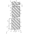
より詳細には、支持セル12は、図3に示すように、合成樹脂などの可撓性膜で形成された上外膜14と下外膜16の間に流体室としての受圧流体室18を備える中空構造を有しており、受圧流体室18に対して弾性体としての支持弾性体20が収容されている。本実施形態では、上外膜14が下向きに開口する逆向き凹形状とされていると共に、下外膜16が上向きに開口する凹形状とされており、上外膜14の開口部と下外膜16の開口部が突き合わされることによって、それら上外膜14と下外膜16の間に受圧流体室18が形成されている。また、受圧流体室18に配設される支持弾性体20は、好適には連続気泡を有する多孔質の弾性体とされており、例えば発泡率の大きな発泡ウレタンフォームなどで形成されている。
More specifically, as shown in FIG. 3, the
そして、支持セル12は、上外膜14と下外膜16の変形が受圧流体室18内に対する空気の流入と排出によって許容されて、上下方向に伸縮変形可能とされている。なお、受圧流体室18内の流体は、空気以外の気体であっても良いし、液体であっても良いが、好適には圧縮性流体とされることにより、流体の圧縮性によって衝撃的な荷重作用時のクッション性が向上し得ると共に、荷重作用時に外膜14,16への作用力が流体の圧縮性によって軽減されて、耐久性や耐荷重性能の向上が図られ得る。本実施形態では、受圧流体室18内の流体が空気とされている。
The
さらに、支持セル12は、複数が一体的に形成されている。即ち、支持セル12はマットレス10の幅方向(図1中の左右方向)に並ぶ複数が配設されており、幅方向に並ぶ複数の支持セル12は、それらの上外膜14が相互に繋がって一体形成されていると共に、それらの下外膜16が相互に繋がって一体形成されている。本実施形態では、支持セル12はマットレス10の長さ方向(図1中の上下方向)にも複数が並んで配設されており、長さ方向に並ぶ複数の支持セル12も、それらの上外膜14が相互に繋がって一体形成されていると共に、それらの下外膜16が相互に繋がって一体形成されている。
Further, a plurality of
一方、幅方向左右に並ぶ複数の支持セル12の幅方向外側には、それぞれ流体セルとしての補助セル22が配設されている。補助セル22は、可撓性の合成樹脂膜などで形成された上外膜24と下外膜26の間に流体室としての補助流体室28を備える中空構造を有していると共に、補助流体室28に弾性手段としての作用弾性体30が収容された構造とされている。そして、補助セル22は、上外膜24と下外膜26の変形が補助流体室28内に対する空気の流入と排出によって許容されて、上下方向に伸縮変形可能とされることで容積可変とされている。
On the other hand,
本実施形態の補助セル22では、凹状部分としての上外膜24が支持セル12の上外膜14と同様の下向きに開口する逆向き凹形状とされていると共に、凹状部分としての下外膜26が支持セル12の下外膜16と同様の上向きに開口する凹形状とされており、上外膜24の開口部と下外膜26の開口部が相互に突き合されることによって、それら上外膜24と下外膜26の間に補助流体室28が形成されている。
In the
また、補助流体室28に収容される作用弾性体30は、支持セル12の支持弾性体20と略同一のスポンジとされており、部品の共通化によるコストの低減や製造及び管理の簡単化が図られている。要するに、本実施形態の補助セル22は、支持セル12と略同じ構造とされており、マットレス10の幅方向の両端に配設されている。
In addition, the working
かくの如き構造とされた補助セル22は、幅方向で並んで配置される支持セル12と一体的に繋がっている。即ち、補助セル22の上外膜24と支持セル12の上外膜14が幅方向で相互に繋がって一体形成されていると共に、補助セル22の下外膜26と支持セル12の下外膜16が幅方向で相互に繋がって一体形成されている。
The
さらに、長さ方向に並んで配置される複数の補助セル22は、相互に一体的に繋がって形成されている。即ち、長さ方向に並ぶ複数の補助セル22の上外膜24が相互に繋がって一体形成されていると共に、長さ方向に並ぶ複数の補助セル22の下外膜26が相互に繋がって一体形成されている。
Further, the plurality of
本実施形態では、凹状部分としての複数の上外膜14および複数の上外膜24を連続的に一体形成した上シート32と、凹状部分としての複数の下外膜16および複数の下外膜26を連続的に一体形成した下シート34が、上下に重ね合わされて固着されることにより、複数の支持セル12および複数の補助セル22が一体的に繋がって形成されている。
In the present embodiment, an
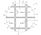
さらに、上シート32における複数の支持セル12の上外膜14の周囲には、平坦な上重ね部36が設けられている。上重ね部36は、各上外膜14の開口部の外周を囲むように形成されて、隣り合う上外膜14,14の間および隣り合う上外膜14,24の間を延びている。本実施形態の上重ね部36は、各上外膜24の周囲にも形成されており、隣り合う上外膜24,24の間を延びていると共に、上シート32の外周端部に全周に亘って連続する環状(枠状)で設けられている。本実施形態では、図1に示すように、上外膜14および上外膜24が平面視で略四角形とされていることから、上重ね部36が平面視で略格子状に形成されている。
Further, a flat
更にまた、下シート34における複数の支持セル12の下外膜16の周囲には、平坦な下重ね部38が設けられている。下重ね部38は、隣り合う下外膜16,16の間および隣り合う下外膜16,26の間を延びて、各下外膜16の開口部の外周を囲むように形成されている。本実施形態の下重ね部38は、各下外膜26の周囲にも形成されており、隣り合う下外膜26,26の間を延びていると共に、下シート34の外周端部に全周に亘って連続する環状(枠状)で設けられている。本実施形態では、下外膜16および下外膜26が底面視で略四角形とされていることから、下重ね部38が底面視で略格子状に形成されている。また、上外膜14,24の開口部と下外膜16,26の開口部が相互に対応する形状とされていることから、上外膜14,24の開口部の周囲に形成される上重ね部36と、下外膜16,26の開口部の周囲に形成される下重ね部38が、相互に対応する形状とされている。
Furthermore, a flat
そして、上シート32の上重ね部36と下シート34の下重ね部38が上下に重ね合わされて、それら上重ね部36と下重ね部38が相互に溶着されることにより、上外膜14,24と下外膜16,26が相互に開口部を覆うように突き合わされて、支持セル12および補助セル22が形成されている。即ち、上下の重ね部36,38は、全体が相互に重ね合わされていると共に、図4に斜線のハッチングを付して示すように、後述する連通路44,46の形成部分を除く部分(固着領域40)において部分的に溶着されている。
Then, the upper overlapping
図4に示す上下の重ね部36,38の幅寸法Wは、溶着のし易さや溶着の信頼性の確保などの観点から3mm以上とされていることが望ましいと共に、支持セル12および補助セル22の相互間の距離(間隔)が大きくなりすぎるのを防いで、違和感のない支持面11を構成するために、15mm以下とされていることが望ましい(3mm≦W≦5mm)。
The width dimension W of the upper and lower overlapping
さらに、上下の重ね部36,38において相互に溶着される領域(固着領域40)の幅W’は、上下の重ね部36,38の幅寸法Wに対して20%以上且つ80%以下とされていることが望ましい。蓋し、固着領域40の幅W’が上下の重ね部36,38の幅寸法Wに対して20%未満とされていると、固着領域40が狭くなりすぎて、溶着の耐久性や信頼性が十分に確保できなくなるおそれがある一方、80%を超えると、上重ね部36と下重ね部38の面方向での相対位置の誤差などに起因して、固着領域40の実質的な幅寸法を安定して確保することが難しくなるなどの不具合が生じ得るからである。なお、固着領域40は、上下の重ね部36,38の幅方向中央部分に設定されることが望ましく、これによって、上下の重ね部36,38の相対位置や溶着位置の誤差などが許容され易くなる。
Further, the width W ′ of the region (fixed region 40) welded to each other in the upper and lower overlapping
ここにおいて、上下の重ね部36,38には、複数の非固着領域42が設けられている。この非固着領域42は、上下の重ね部36,38が溶着されることなく非固着で重ね合わされた領域であって、上下の重ね部36,38が変形によって相互に離隔可能とされている。本実施形態の非固着領域42は、支持セル12および補助セル22の幅方向間に設けられており、上下の重ね部36,38の幅方向全長に亘って連続して設けられている。更に、本実施形態の非固着領域42は、支持セル12および補助セル22の幅方向間においてマットレス10の長さ方向で中央に位置している。
Here, a plurality of
また、非固着領域42における上重ね部36と下重ね部38の重ね合わせ面間には、連通路44,46が形成されており、幅方向で隣接して配された支持セル12,12の受圧流体室18,18間が連通路44によって相互に連通されていると共に、支持セル12の受圧流体室18と補助セル22の補助流体室28が連通路46によって相互に連通されている。
Further,
本実施形態では、上重ね部36の下面と下重ね部38の上面がそれぞれ平面とされており、連通路44,46内が大気圧とされた初期状態において、上重ね部36の下面と下重ね部38の上面が非固着領域42で当接している。更に、連通路44,46内が大気圧とされた初期状態において、図3に示すように、上重ね部36と下重ね部38の密着状態での当接によって、連通路44,46が遮断されている。
In the present embodiment, the lower surface of the upper overlapping
そして、非固着領域42において上重ね部36と下重ね部38の重ね合わせ面間に大気圧よりも大きな圧力が作用することにより、図5,6に示すように、非固着領域42の上重ね部36と下重ね部38が相互に離隔するように変形せしめられて、非固着領域42において上重ね部36と下重ね部38の重ね合わせ面間で連通路44,46が開口して連通状態とされるようになっている。連通路44,46は、最大通路断面積が受圧流体室18および補助流体室28の断面積よりも小さくされており、幅方向で隣り合う支持セル12,12の受圧流体室18,18および支持セル12の受圧流体室18と補助セル22の補助流体室28は、狭窄された連通路44,46によって相互に連通される。なお、図6中には、初期状態において連通路44が閉じた状態が二点鎖線で図示されている。
Then, when a pressure larger than the atmospheric pressure acts between the overlapping surfaces of the upper overlapping
さらに、連通路44,46内の圧力に応じて非固着領域42における上重ね部36と下重ね部38の重ね合わせ方向での離隔距離が変化して、連通路44,46の通路断面積が変化するようになっている。このように連通路44,46の通路断面積が可変とされていることによって、連通路44,46における流体の流動特性(流通抵抗など)が、連通路44,46内の圧力に応じて受動的に変更されるようになっている。なお、連通路44,46の壁部を構成する上シート32と下シート34は、ある程度の弾性的な伸縮性を有する材料で形成されていることが望ましく、非固着領域42における上シート32と下シート34の伸長変形によって連通路44,46が連通状態に切り替えられる。
Further, the separation distance in the overlapping direction of the
また、本実施形態では、マットレス幅方向に並んで配設された複数の支持セル12の受圧流体室18が、複数の連通路44によって直列的に連通されていると共に、それら幅方向に並んで配設された複数の支持セル12に対して幅方向両側にそれぞれ補助セル22が配設されている。そして、連通路44によって相互に連通された支持セル12の幅方向両側に配設される補助セル22,22の補助流体室28,28が、支持セル12の受圧流体室18に対して連通路46によって連通されている。なお、連通路44,46によって連通された複数の支持セル12の受圧流体室18と複数の補助セル22の補助流体室28は、大気に開放されることなく密閉状態とされており、大気中への空気の放出が回避されていることで底付きの発生などが防止されている。
In the present embodiment, the pressure receiving
このような構造とされたマットレス10は、ベッド48の上に敷かれて使用される。即ち、マットレス10は、ベッド48の上面と図示しない使用者の間に配設されて、使用者を緩衝的に支持するようになっており、使用者を支持する支持面11がマットレス10の上面で構成されている。そして、使用者がマットレス10の支持面11に対して及ぼす圧力(体圧)に応じて支持面11を構成する支持セル12が伸縮することにより、支持面11に作用する使用者の支持荷重が広範囲に分散して、使用者に良好な寝心地を提供することなどが可能とされている。
The
ここにおいて、支持セル12に使用者の体圧が作用して上下に圧縮されることにより、支持セル12の受圧流体室18内の圧力が大気圧よりも大きくなると、支持セル12の周囲に設けられた非固着領域42において上重ね部36と下重ね部38の重ね合わせ面間の圧力が大気圧よりも大きくなる。これにより、上重ね部36と下重ね部38が非固着領域42において相互に離れるように変形して、非固着領域42における上重ね部36と下重ね部38の間に連通路44,46が開口する。この連通路44,46を通じて圧縮された支持セル12の受圧流体室18から空気が排出されることにより、支持セル12の収縮変形が許容されるようになっている。
Here, when the pressure in the pressure receiving
さらに、連通路44で連通された複数の支持セル12に対して圧縮荷重が作用する場合には、より大きな圧縮荷重が作用する支持セル12の受圧流体室18から小さな圧縮荷重が作用する支持セル12の受圧流体室18へ連通路44を通じて空気が流動して、それら支持セル12が入力された圧縮荷重の大きさに応じて伸縮変形するようになっている。
Further, when a compressive load acts on the plurality of
更にまた、荷重が作用し難いマットレス10の幅方向両端部には、連通路46によって支持セル12の受圧流体室18に連通された補助流体室28を備える補助セル22が設けられており、支持セル12に圧縮荷重が作用すると、支持セル12の受圧流体室18から排出された空気が連通路46を通じて補助セル22の補助流体室28に流入するようになっている。これにより、支持セル12の収縮変形量がより大きく確保されて、体圧の分散効果がより有利に発揮される。
Furthermore, the
このような本実施形態に従う構造とされたマットレス10によれば、非固着領域42における上シート32の上重ね部36と下シート34の下重ね部38の重ね合わせ方向での距離が、連通路44内の圧力に応じて変化するようになっており、連通路44は通路断面積が内圧変化に伴って可変とされている。これにより、連通路44を通じた流体の流動特性(流通抵抗など)が内圧に応じて受動的に変化するようになっており、複数の支持セル12の受圧流体室18間における連通路44を通じた流体の流動量が支持面11への入力に応じて調節される。その結果、支持セル12の伸縮変形特性が入力に応じて調節されて、支持セル12によって構成される支持面11の変形特性が入力に応じて調節されることから、支持面11の変形を許容することによる体圧分散作用と、支持面11の変形を制限することによる安定した支持や良好なクッション作用などを、適当に得ることが可能になる。
According to the
具体的には、例えば、支持面11に対する荷重の入力初期には、連通路44が遮断状態乃至は小さな通路断面積の連通状態とされて、連通路44で連通された複数の支持セル12の受圧流体室18間において流体流動量が制限されることから、支持セル12において弾性的な反発力が十分に発揮されて、使用者などを安定して支持することができる。一方、荷重の入力開始から時間が経過するに従って連通路44の通路断面積が大きくなることにより、連通路44で連通された複数の支持セル12の受圧流体室18間において流体の流動量が増加することから、支持セル12の伸縮変形が十分に許容されて、体圧分布に対応する支持面11の変形によって体圧の分散化が図られる。
Specifically, for example, at the initial stage of input of the load to the
また、入力荷重が小さい場合には、連通路44において小さな通路断面積が維持されて、支持セル12の変形量が制限されることから、支持面11が過剰に変形することなく形状の安定性と十分なクッション作用が確保される。一方、特定の支持セル12に大きな荷重が入力される場合には、連通路44の内圧が高まって連通路44の通路断面積が大きくなることから、入力を受けた支持セル12の伸縮変形が大きなストロークで許容されて、支持面11の変形による体圧分散作用が有効に実現される。
In addition, when the input load is small, a small passage cross-sectional area is maintained in the
本実施形態では、支持セル12の受圧流体室18と補助セル22の補助流体室28を相互に連通する連通路46が、支持セル12の受圧流体室18間を相互に連通する連通路44と同じ構造とされていることから、支持セル12と補助セル22の間における連通路46を通じた流体流動についても、複数の支持セル12間における連通路44を通じた流体流動と同様の効果を得ることができる。
In this embodiment, the
また、補助セル22は、連通路44によって幅方向で直列的に連通された複数の支持セル12に対して幅方向両側にそれぞれ配設されて、それら支持セル12と連通路46によって連通されている。これにより、幅方向に並んで配置された全ての支持セル12が、幅方向両側に設けられた連通路44,44又は連通路44,46によって空気の流入と流出を許容されており、伸縮変形を十分に許容されるようになっている。
The
一方、補助セル22は、マットレス10の幅方向両端部に配されることで、使用者が寝ている状態では荷重が作用し難くなっており、支持セル12の受圧流体室18から排出された流体が補助流体室28に流入することで、支持セル12の伸縮変形を補助するようになっている。更に、補助セル22は、幅方向内側にのみ連通路46が設けられていることから、支持セル12に比して伸縮変形し難くなっており、補助セル22に荷重が入力される手および膝などを突いた姿勢や端座時などにおいて、弾性的な反発力が十分に大きく発揮されて安定した支持が実現される。特に、補助セル22と支持セル12を繋ぐ連通路46が、複数の支持セル12を相互に繋ぐ連通路44と同様の構造を有していることから、入力初期には連通路46の通路断面積が十分に小さくされており、連通路46を通じた流体の流動量が制限されることで、補助セル22の弾性的な反発力をより有利に得ることができる。
On the other hand, the
また、本実施形態では、上シート32における複数の上外膜14の周囲に平坦な上重ね部36が形成されていると共に、下シート34における複数の下外膜16の周囲に平坦な下重ね部38が形成されており、それら上重ね部36と下重ね部38を相互に重ね合わせて固着することで、複数の支持セル12が一体的に形成されている。これにより、複数の支持セル12を一体的に取り扱うことが可能となると共に、上外膜14と下外膜16の間に容積の大きな受圧流体室18を形成することができる。
In the present embodiment, a flat
しかも、それぞれ所定の幅を有する上重ね部36と下重ね部38を相互に重ね合わせて固着することにより、上シート32と下シート34の重ね合わせ方向(上下方向)と直交する面方向において、上シート32と下シート34の相対的な位置のずれが許容される。蓋し、上外膜14,24と下外膜16,26の開口端部の位置が面方向で相対的に多少ずれたとしても、上重ね部36と下重ね部38が幅を有することによって、上外膜14,24と下外膜16,26の開口部の周囲を相互に固着して受圧流体室18および補助流体室28を画成することが可能となるからである。なお、上シート32と下シート34の固着領域40を確保するために、面方向における上シート32と下シート34の相対的な位置のずれは、上下重ね部36,38の幅に対して20%未満、より好適には10%未満とされることが望ましい。
In addition, in the surface direction orthogonal to the overlapping direction (vertical direction) of the
図7には、本発明の第二の実施形態としての流体セル式マットレス50が示されている。このマットレス50は、幅方向中間部分に配設される複数の流体セルとしての支持セル52と幅方向両端部分に配設される複数の流体セルとしての補助セル54とを備えており、第一の実施形態と同様の上シート32と平坦な下シート56を重ね合わせて固着した構造を有している。以下の説明において、第一の実施形態と実質的に同一であると把握される部材および部位については、図中に同一の符号を付すことにより、説明を省略する。
FIG. 7 shows a
より詳細には、下シート56は、全体が平膜状とされており、下外膜58が下重ね部38と連続する平坦な形状とされている。そして、上シート32の上重ね部36と下シート56の下重ね部38が、固着領域40において相互に当接状態で重ね合わされて溶着されていると共に、非固着領域42において相互に非固着で重ね合わされている。これにより、上外膜14と下外膜58の間に受圧流体室18が画成されて、内部にそれぞれ受圧流体室18を備える複数の支持セル52が一体的に形成されている。
More specifically, the lower sheet 56 has a flat film shape as a whole, and has a flat shape in which the lower
また、幅方向に並んで配された複数の支持セル52の受圧流体室18が連通路44によって直列的に連通されていると共に、連通路44で受圧流体室18を相互に連通された複数の支持セル52の幅方向両側には、補助セル54が配設されている。
The pressure receiving
この補助セル54は、上シート32の上外膜24と下シート56の下外膜60の間に中間膜62を配設した構造を有しており、上外膜24と下外膜60の間に画成された補助流体室28が中間膜62によって上下に仕切られて、中間膜62の上側に拡縮補助室64が形成されていると共に、中間膜62の下側に作用室66が形成されている。中間膜62は、上外膜24と略同じ下向きに開口する逆向き凹形状を有しており、開口端部が全周に亘って下シート56に溶着されている。これにより、作用室66が支持セル52の受圧流体室18に対して流体密に隔てられていると共に、拡縮補助室64が連通路46を通じて支持セル52の受圧流体室18に連通されている。
The
また、作用室66には作用弾性体30が配設されており、中間膜62が作用弾性体30によって拡縮補助室64側へ付勢されるようになっている。更に、作用室66の壁部を構成する下外膜60には貫通孔68が形成されており、作用室66が貫通孔68を通じて大気に開放されている。
The action
このような本実施形態に従う構造とされたマットレス50によっても明らかなように、上シート32と下シート56にそれぞれ凹状部分を設ける必要はなく、何れか一方に凹状部分を設けると共に、何れか他方を凹状部分のない平坦な形状とすることもできる。これによれば、上シート32と下シート56の面方向での位置ずれがより大きく許容されて製造が容易になり得る。
As is clear from the
また、本実施形態に係るマットレス50において、支持面11に荷重が入力されて支持セル52が上下に圧縮されると、支持セル52の受圧流体室18から補助セル54の拡縮補助室64へ流体が流入して、拡縮補助室64の内圧が上昇する。これにより、中間膜62が作用弾性体30の付勢力に抗して下方へ変位せしめられて、拡縮補助室64の容積が大きくなる。これにより、補助セル54において外膜24,60の大きな変形を伴うことなく、支持セル52の伸縮変形を大きなストロークで許容することができて、体圧の分散化を有利に実現することができる。
Further, in the
しかも、支持セル52に対する入力が解除されると、中間膜62が作用弾性体30の弾性によって拡縮補助室64側へ変位せしめられることで拡縮補助室64から流体が排出されて、拡縮補助室64から排出された流体が支持セル52の受圧流体室18へ流入することにより支持セル52の収縮が解除される。
Moreover, when the input to the
図8には、本発明の第三の実施形態としての流体セル式マットレス70の要部が示されている。本実施形態のマットレス70は、支持セル12の受圧流体室18間を相互に連通する連通路44が、相互に通路形状の異なる連通路44aと連通路44bを有している。
The principal part of the fluid
より具体的には、連通路44aの通路幅W1 が連通路44bの通路幅W2 よりも大きくされている(W1 >W2 )と共に、連通路44aの通路長L1 が連通路44bの通路長L2 よりも小さくされている(L1 <L2 )。これらにより、連通路44aにおける流体の流通抵抗が、連通路44bにおける流体の流通抵抗よりも小さくされており、連通路44aを通じた流体流動が生じ易くなっている一方、連通路44bを通じた流体流動が生じ難くなっている。
More specifically, the passage width W 1 of the communication passage 44a is larger than the passage width W 2 of the
このような本実施形態に従う構造とされたマットレス70によれば、支持面11への荷重入力に対して、連通路44aで連通された支持セル12の受圧流体室18間において流体流動が優先的に生ぜしめられて、連通路44aで相互連通された支持セル12によって構成される支持面11の領域では、入力に応じた変形が速やかに完了する。一方、連通路44bで連通された支持セル12の受圧流体室18間において流体流動が緩やかに生じることから、連通路44bで相互連通された支持セル12によって構成される支持面11の領域では、入力初期に弾性的な反発力によるクッション作用が有利に発揮される。
According to the
なお、複数種類の連通路において、通路長と通路幅の両方が異なっている必要はなく、通路長と通路幅の何れか一方だけを異ならせてそれら連通路の流通抵抗を異ならせることもできる。更にまた、長い通路長と広い通路幅を有する連通路と、短い通路長と狭い通路幅を有する連通路を、組み合わせて採用しても良い。 In addition, in a plurality of types of communication paths, both the passage length and the passage width need not be different, and only one of the passage length and the passage width can be varied to vary the flow resistance of these communication paths. . Furthermore, a communication passage having a long passage length and a wide passage width and a communication passage having a short passage length and a narrow passage width may be used in combination.
また、通路長と通路幅の少なくとも一方が相互に異なる3種類以上の連通路を組み合わせて採用しても良い。 Moreover, you may employ | adopt combining 3 or more types of communicating paths from which at least one of a passage length and a passage width mutually differs.
本実施形態では、支持セル12間の連通路44を通路形状が異なる2種類によって構成した例を示したが、例えば支持セル12間の連通路44と支持セル12と補助セル22の間の連通路46が、通路幅と通路長の少なくとも一方を相互に異ならせた別種類の連通路とされていても良い。具体的には、例えば、連通路44の通路幅を連通路46の通路幅よりも大きくすると共に、連通路44の通路長を連通路46の通路長よりも短くすることも可能である。
In the present embodiment, the example in which the
このような支持セル12間の連通路44と支持セル12と補助セル22の間の連通路46の通路幅および通路長を異ならせた構造によれば、支持面11への荷重入力に対して、支持セル12間での流体流動が優先的に生ぜしめられて、支持面11における支持セル12で構成される領域の変形が速やかに完了する。一方、支持セル12から補助セル22への流体流動が追従して生ぜしめられることにより、体圧分布に応じて変形した支持面11における支持セル12で構成される領域の形状を略保ちつつ、支持面11における当該領域全体の圧力が低減されて、体圧の低減による良好な寝心地などが実現される。
According to such a structure in which the passage width and the passage length of the
しかも、補助セル22から支持セル12への流体流動が抑制的に生ぜしめられることから、端座時など補助セル22に荷重が入力される場合に、補助セル22の弾性的な反発力がより効果的に発揮されて、安定した支持を実現することができる。
In addition, since the fluid flow from the
なお、支持セル12間に設けられる連通路44が、通路幅が小さく且つ通路長の長い形状とされると共に、補助セル22と支持セル12の間に設けられる連通路46が、通路幅が大きく且つ通路長の短い形状とされていても良い。これによれば、例えば、幅方向両側に連通路を設けられる支持セル12の変形特性と、幅方向片側だけに連通路を設けられる補助セル22の変形特性を、略同じに設定することなども可能になり得る。
The
図9には、本発明の第四の実施形態としての流体セル式マットレス80の要部が示されている。本実施形態のマットレス80では、上シート32の上重ね部36と下シート34の下重ね部38が、非固着領域42においてそれぞれ波打ち形状とされており、連通路44内が略大気圧とされた初期状態において、連通路44が遮断されることなく連通状態に保持されている。
FIG. 9 shows a main part of a fluid
より詳細には、上シート32の上重ね部36は、非固着領域42において、長さ方向(図9中、左右方向)の中央部分が下向きに凸の湾曲形状とされているとともに長さ方向の両側部分が上向きに凸の湾曲形状とされた波打ち状の断面形状を有している。一方、下シート34の下重ね部38は、非固着領域42において、長さ方向の中央部分が上向きに凸の湾曲形状とされているとともに長さ方向の両側部分が下向きに凸の湾曲形状とされた波打ち状の断面形状を有している。なお、上下の重ね部36,38は、固着領域40において何れも平坦な形状とされている。
More specifically, the upper overlapping
そして、上下に重ね合わされた上重ね部36と下重ね部38は、非固着領域42において、長さ方向の中央部分が相互に当接していると共に、長さ方向の両側部分が上下に離れており、長さ方向の両端部分において連通路44が連通状態とされている。要するに、本実施形態の非固着領域42では、上シート32の上重ね部36と下シート34の下重ね部38が部分的に当接しており、当接部分を外れた領域で連通路44が連通状態とされている。
The upper overlapped
このような本実施形態に従う構造とされたマットレス80によれば、非固着領域42において上重ね部36と下重ね部38が部分的に当接しており、連通路44が常時連通状態で形成されていることにより、上重ね部36と下重ね部38の密着が防止されて、目的とする特性を高い信頼性で実現することができる。しかも、連通路44内が大気圧とされた初期状態における連通路44の通路断面積を調節することによって、支持面に対する荷重入力初期における支持面の変形特性を調節することができる。
According to the
さらに、上下の重ね部36,38が非固着領域42において波打ち状断面とされていることにより、上下の重ね部36,38が非固着領域42において弛みを備えており、非固着領域42における上下の重ね部36,38の変形がある程度までは容易に許容されるようになっている。これにより、入力初期の支持面の変形特性を柔らかく設定することができる。
Further, since the upper and lower overlapping
また、上下の重ね部36,38が非固着領域42において弛みを持っていることにより、非固着領域42の長さ(図9中の左右方向寸法)に対して、連通路44の最大通路断面積をより大きく得ることができて、連通路44の通路断面積の設定自由度を高くなる。
Further, since the upper and lower overlapping
なお、本実施形態では、上重ね部36と下重ね部38がそれぞれ波打ち状の断面形状を有することによって、連通路44内が大気圧とされた初期状態において連通路44が連通状態に保持されるようになっているが、例えば、上重ね部と下重ね部の重ね合わせ面の少なくとも一方に対して、突出部を形成する或いは粗面加工を施すなどすることにより、上重ね部と下重ね部の重ね合わせ面間に隙間を形成して、連通路内が大気圧とされた初期状態において連通路が連通状態に保持されるようにしても良い。
In the present embodiment, the
以上、本発明の実施形態について詳述してきたが、本発明はその具体的な記載によって限定されない。例えば、上シートと下シートは必ずしも全体が一定の厚さや材質で形成されている必要はなく、非固着領域において厚さや材質を部分的に異ならせることによって、連通路の通路断面積の変化を制御して、連通路における流体の流動特性を調節することもできる。 As mentioned above, although embodiment of this invention was explained in full detail, this invention is not limited by the specific description. For example, the upper sheet and the lower sheet do not necessarily have to be formed with a constant thickness or material as a whole, and the passage cross-sectional area of the communication path can be changed by partially varying the thickness or material in the non-adhering region. It is also possible to control and adjust the flow characteristics of the fluid in the communication path.
また、前記実施形態では、上シートが複数の凹状部分(上外膜)の間に平坦な上重ね部が形成された構造とされていると共に、下シートが複数の凹状部分(下外膜)の間に平坦な下重ね部が形成された構造とされており、それら上重ね部と下重ね部が重ね合わされて固着領域で相互に固着された構造とされている。それら上重ね部と下重ね部は、固着強度の確保や製造の容易化、部材寸法や位置決めの誤差の許容などを実現するために設けられることが望ましいが、省略することも可能であり、例えば、上シートの凹状部分の開口部と下シートの凹状部分の開口部が相互に突き合わされて固着された構造であっても良い。 In the embodiment, the upper sheet has a structure in which a flat upper overlap portion is formed between a plurality of concave portions (upper outer membrane), and the lower sheet has a plurality of concave portions (lower outer membrane). A flat lower overlapping portion is formed between the upper overlapping portion and the lower overlapping portion, and the upper overlapping portion and the lower overlapping portion are overlapped and fixed to each other in the fixing region. These upper and lower overlapped portions are preferably provided in order to ensure securing strength, facilitate manufacturing, allow tolerances of member dimensions and positioning, etc., but can be omitted, for example, The opening of the concave portion of the upper sheet and the opening of the concave portion of the lower sheet may be abutted against each other and fixed.
前記実施形態では、流体セルとして支持セルと補助セルを備える流体セル式マットレスを例示したが、例えば流体セルの全てが支持セルで構成されて、補助セルをもたない構造であっても良い。また、支持面が部分的にウレタンフォームなどで構成されていても良く、支持面において流体セルで構成されていない部分があっても良い。 In the embodiment, the fluid cell mattress including the support cell and the auxiliary cell is illustrated as the fluid cell. However, for example, a structure in which all the fluid cells are configured by the support cell and do not have the auxiliary cell may be used. Further, the support surface may be partially made of urethane foam or the like, and there may be a portion that is not made of a fluid cell on the support surface.
また、前記実施形態では、マットレス幅方向で隣り合う流体セルの流体室間が連通路によって幅方向でのみ連通された構造を例示したが、例えば、マットレス幅方向に延びる連通路に替えて或いは加えてマットレス長さ方向に延びる連通路を形成して、長さ方向で隣り合う流体セルの流体室間を連通路によって連通することもできる。なお、幅方向および長さ方向以外の面方向で隣り合う流体セルの流体室間を連通路によって連通しても良いことは言うまでもないし、面方向で隣り合うことなく離れて配された流体セルの流体室間を連通路によって連通しても良い。更に、例えば、隣り合う流体セルの間に同じ方向に延びる複数の連通路を並列的に形成することも可能であり、これによって流体セルにおける上シートと下シートの固着強度を確保しながら、連通路の通路断面積を大きく確保することが可能になる。 In the above-described embodiment, the structure in which the fluid chambers of the fluid cells adjacent in the mattress width direction are communicated only in the width direction by the communication path. However, for example, instead of or in addition to the communication path extending in the mattress width direction. Thus, a communication passage extending in the length direction of the mattress can be formed, and the fluid chambers of fluid cells adjacent in the length direction can be communicated with each other by the communication passage. Needless to say, the fluid chambers of fluid cells adjacent in a plane direction other than the width direction and the length direction may be communicated with each other by a communication path. You may communicate between fluid chambers by a communicating path. Further, for example, a plurality of communication passages extending in the same direction can be formed in parallel between adjacent fluid cells, thereby securing the bonding strength between the upper sheet and the lower sheet in the fluid cell, while communicating with each other. A large passage cross-sectional area of the passage can be secured.
また、全ての連通路が本発明に係る構造とされている必要はなく、例えば、補助セルが支持セルに対して離れた位置に配される場合などには、支持セルと補助セルを上下シートとは別体のチューブによって形成された連通路によって繋ぐことも可能である。同様に、支持セル間を繋ぐ連通路の一部に上記チューブを用いることも可能である。 In addition, it is not necessary that all the communication passages have the structure according to the present invention. For example, when the auxiliary cell is arranged at a position separated from the support cell, the support cell and the auxiliary cell are connected to the upper and lower sheets. It is also possible to connect by a communication path formed by a separate tube. Similarly, it is possible to use the tube in a part of the communication path connecting the support cells.
本発明は、例えば、支持面の圧力分布を圧力センサによって検出して、検出された圧力分布に応じてポンプを制御することで、支持セルの流体室に対する流体の給排をポンプによって実行し、支持セルを能動的に伸縮変形させる、アクティブ制御タイプの流体セル式マットレスにも適用可能である。 The present invention, for example, detects the pressure distribution on the support surface with a pressure sensor, and controls the pump according to the detected pressure distribution, thereby performing the supply and discharge of fluid to and from the fluid chamber of the support cell, The present invention can also be applied to an active control type fluid cell type mattress that actively expands and contracts the support cell.
10,50,70,80:流体セル式マットレス、11:支持面、12,52:支持セル(流体セル)、14:上外膜(凹状部分)、16:下外膜(凹状部分)、18:受圧流体室(流体室)、22,54:補助セル(流体セル)、24:上外膜(凹状部分)、26,58,60:下外膜(凹状部分)、28:補助流体室(流体室)、32:上シート、34,56:下シート、36:上重ね部、38:下重ね部、40:固着領域、42:非固着領域、44:連通路、46:連通路 10, 50, 70, 80: fluid cell mattress, 11: support surface, 12, 52: support cell (fluid cell), 14: upper outer membrane (concave portion), 16: lower outer membrane (concave portion), 18 : Pressure receiving fluid chamber (fluid chamber), 22, 54: auxiliary cell (fluid cell), 24: upper outer membrane (concave portion), 26, 58, 60: lower outer membrane (concave portion), 28: auxiliary fluid chamber ( Fluid chamber), 32: upper sheet, 34, 56: lower sheet, 36: upper overlap part, 38: lower overlap part, 40: fixing area, 42: non-adhesion area, 44: communication path, 46: communication path
Claims (11)
前記流体セルが相互に重ね合わされる上シートと下シートを含んで構成されており、それら上シートと下シートによって複数の該流体セルが一体的に形成されていると共に、それら複数の流体セルの周囲において該上シートと該下シートが相互に重ね合わされて固着されている一方、
該流体セルの周囲において該上シートと該下シートが部分的に非固着で重ね合わされており、それら上シートと下シートの非固着領域の重ね合わせ面間に前記流体室を相互に連通する連通路が形成されていると共に、該上シートと該下シートの非固着領域における重ね合わせ面間の距離が該連通路内の圧力に応じて変化することで該連通路の通路断面積が可変とされていることを特徴とする流体セル式マットレス。 A fluid cell type mattress in which at least a part of a support surface on which a user is placed is configured by a fluid cell having a fluid chamber therein and made extendable and contractible,
The fluid cell is configured to include an upper sheet and a lower sheet that are superposed on each other, and the plurality of fluid cells are integrally formed by the upper sheet and the lower sheet. While the upper sheet and the lower sheet are superposed and fixed around each other,
Around the fluid cell, the upper sheet and the lower sheet are partially overlapped with each other in a non-adhering manner, and the fluid chamber communicates between the overlapping surfaces of the non-adhering regions of the upper sheet and the lower sheet. A passage is formed, and the cross-sectional area of the communication passage is variable by changing the distance between the overlapping surfaces in the non-fixed region of the upper sheet and the lower sheet according to the pressure in the communication passage. A fluid cell type mattress characterized by being made.
Priority Applications (1)
| Application Number | Priority Date | Filing Date | Title |
|---|---|---|---|
| JP2016097861A JP2017205154A (en) | 2016-05-16 | 2016-05-16 | Fluid cell-type mattress |
Applications Claiming Priority (1)
| Application Number | Priority Date | Filing Date | Title |
|---|---|---|---|
| JP2016097861A JP2017205154A (en) | 2016-05-16 | 2016-05-16 | Fluid cell-type mattress |
Publications (1)
| Publication Number | Publication Date |
|---|---|
| JP2017205154A true JP2017205154A (en) | 2017-11-24 |
Family
ID=60414654
Family Applications (1)
| Application Number | Title | Priority Date | Filing Date |
|---|---|---|---|
| JP2016097861A Pending JP2017205154A (en) | 2016-05-16 | 2016-05-16 | Fluid cell-type mattress |
Country Status (1)
| Country | Link |
|---|---|
| JP (1) | JP2017205154A (en) |
Cited By (1)
| Publication number | Priority date | Publication date | Assignee | Title |
|---|---|---|---|---|
| JP2021132815A (en) * | 2020-02-26 | 2021-09-13 | 住友理工株式会社 | Fluid cell for body pressure support |
Citations (4)
| Publication number | Priority date | Publication date | Assignee | Title |
|---|---|---|---|---|
| JPS52105392U (en) * | 1976-02-06 | 1977-08-10 | ||
| JPH0994132A (en) * | 1995-04-07 | 1997-04-08 | Dielectrics Ind Inc | Fluid cushion and its preparation |
| JPH10165265A (en) * | 1996-12-06 | 1998-06-23 | S P Chem Kk | Air mattress |
| WO2016051831A1 (en) * | 2014-09-30 | 2016-04-07 | 株式会社ウォーキングDay | Cushion |
-
2016
- 2016-05-16 JP JP2016097861A patent/JP2017205154A/en active Pending
Patent Citations (4)
| Publication number | Priority date | Publication date | Assignee | Title |
|---|---|---|---|---|
| JPS52105392U (en) * | 1976-02-06 | 1977-08-10 | ||
| JPH0994132A (en) * | 1995-04-07 | 1997-04-08 | Dielectrics Ind Inc | Fluid cushion and its preparation |
| JPH10165265A (en) * | 1996-12-06 | 1998-06-23 | S P Chem Kk | Air mattress |
| WO2016051831A1 (en) * | 2014-09-30 | 2016-04-07 | 株式会社ウォーキングDay | Cushion |
Cited By (2)
| Publication number | Priority date | Publication date | Assignee | Title |
|---|---|---|---|---|
| JP2021132815A (en) * | 2020-02-26 | 2021-09-13 | 住友理工株式会社 | Fluid cell for body pressure support |
| JP7355679B2 (en) | 2020-02-26 | 2023-10-03 | 住友理工株式会社 | Fluid cell for body pressure support |
Similar Documents
| Publication | Publication Date | Title |
|---|---|---|
| JP5780643B2 (en) | mattress | |
| CA2855905C (en) | Cellular cushion | |
| JP5719725B2 (en) | Cushion cell and cushion body using the same | |
| US10051972B2 (en) | Mattress | |
| TWI414285B (en) | Air mat with a plurality of air mat layers stacking in vertical direction | |
| WO2017043217A1 (en) | Body pressure support cushion and auxiliary cells constituting same | |
| JP2021167196A (en) | Vehicle seat | |
| JP2017205154A (en) | Fluid cell-type mattress | |
| JP6670667B2 (en) | Air mattress and air mattress device | |
| JP2016087117A (en) | Fluid cell type mattress | |
| JPWO2019031271A1 (en) | Fluid cell mattress | |
| US20180134190A1 (en) | Air bag and vehicle seat device | |
| JP2018046901A (en) | Active-type fluid cell mattress and control method thereof | |
| JP2017104242A (en) | Body pressure support cushion | |
| JP4855952B2 (en) | Cushion body and manufacturing method thereof | |
| JP7355679B2 (en) | Fluid cell for body pressure support | |
| JP2019017729A (en) | Body pressure support cushion and its manufacturing method | |
| JP2016034398A (en) | Cell for mattress and mattress using the same | |
| JP2016209531A (en) | Body pressure support cushion and mattress using the same | |
| JP2013027533A (en) | Mattress | |
| CN106136694A (en) | Body hydraulic support cushion pad and the mattress of this body hydraulic support cushion pad of employing | |
| JP2010046306A (en) | Cushion body | |
| JP2020039485A (en) | Air cell type mattress | |
| WO2020050317A1 (en) | Air mattress and air cell | |
| JP6343735B2 (en) | Air cushion seat and seat |
Legal Events
| Date | Code | Title | Description |
|---|---|---|---|
| A621 | Written request for application examination |
Free format text: JAPANESE INTERMEDIATE CODE: A621 Effective date: 20190221 |
|
| A131 | Notification of reasons for refusal |
Free format text: JAPANESE INTERMEDIATE CODE: A131 Effective date: 20191218 |
|
| A977 | Report on retrieval |
Free format text: JAPANESE INTERMEDIATE CODE: A971007 Effective date: 20191220 |
|
| A02 | Decision of refusal |
Free format text: JAPANESE INTERMEDIATE CODE: A02 Effective date: 20200623 |