JP7345397B2 - Board support device - Google Patents
Board support device Download PDFInfo
- Publication number
- JP7345397B2 JP7345397B2 JP2019559270A JP2019559270A JP7345397B2 JP 7345397 B2 JP7345397 B2 JP 7345397B2 JP 2019559270 A JP2019559270 A JP 2019559270A JP 2019559270 A JP2019559270 A JP 2019559270A JP 7345397 B2 JP7345397 B2 JP 7345397B2
- Authority
- JP
- Japan
- Prior art keywords
- substrate
- coating layer
- support member
- temperature compensation
- temperature
- Prior art date
- Legal status (The legal status is an assumption and is not a legal conclusion. Google has not performed a legal analysis and makes no representation as to the accuracy of the status listed.)
- Active
Links
Images


Classifications
-
- H—ELECTRICITY
- H01—ELECTRIC ELEMENTS
- H01J—ELECTRIC DISCHARGE TUBES OR DISCHARGE LAMPS
- H01J37/00—Discharge tubes with provision for introducing objects or material to be exposed to the discharge, e.g. for the purpose of examination or processing thereof
- H01J37/32—Gas-filled discharge tubes
- H01J37/32431—Constructional details of the reactor
- H01J37/32715—Workpiece holder
- H01J37/32724—Temperature
-
- H—ELECTRICITY
- H10—SEMICONDUCTOR DEVICES; ELECTRIC SOLID-STATE DEVICES NOT OTHERWISE PROVIDED FOR
- H10P—GENERIC PROCESSES OR APPARATUS FOR THE MANUFACTURE OR TREATMENT OF DEVICES COVERED BY CLASS H10
- H10P72/00—Handling or holding of wafers, substrates or devices during manufacture or treatment thereof
- H10P72/70—Handling or holding of wafers, substrates or devices during manufacture or treatment thereof for supporting or gripping
- H10P72/76—Handling or holding of wafers, substrates or devices during manufacture or treatment thereof for supporting or gripping using mechanical means, e.g. clamps or pinches
- H10P72/7604—Handling or holding of wafers, substrates or devices during manufacture or treatment thereof for supporting or gripping using mechanical means, e.g. clamps or pinches the wafers being placed on a susceptor, stage or support
- H10P72/7616—Handling or holding of wafers, substrates or devices during manufacture or treatment thereof for supporting or gripping using mechanical means, e.g. clamps or pinches the wafers being placed on a susceptor, stage or support characterised by a coating, a hardness or a material
-
- H—ELECTRICITY
- H10—SEMICONDUCTOR DEVICES; ELECTRIC SOLID-STATE DEVICES NOT OTHERWISE PROVIDED FOR
- H10P—GENERIC PROCESSES OR APPARATUS FOR THE MANUFACTURE OR TREATMENT OF DEVICES COVERED BY CLASS H10
- H10P72/00—Handling or holding of wafers, substrates or devices during manufacture or treatment thereof
- H10P72/04—Apparatus for manufacture or treatment
- H10P72/0431—Apparatus for thermal treatment
-
- H—ELECTRICITY
- H10—SEMICONDUCTOR DEVICES; ELECTRIC SOLID-STATE DEVICES NOT OTHERWISE PROVIDED FOR
- H10P—GENERIC PROCESSES OR APPARATUS FOR THE MANUFACTURE OR TREATMENT OF DEVICES COVERED BY CLASS H10
- H10P72/00—Handling or holding of wafers, substrates or devices during manufacture or treatment thereof
- H10P72/06—Apparatus for monitoring, sorting, marking, testing or measuring
- H10P72/0602—Temperature monitoring
-
- H—ELECTRICITY
- H10—SEMICONDUCTOR DEVICES; ELECTRIC SOLID-STATE DEVICES NOT OTHERWISE PROVIDED FOR
- H10P—GENERIC PROCESSES OR APPARATUS FOR THE MANUFACTURE OR TREATMENT OF DEVICES COVERED BY CLASS H10
- H10P72/00—Handling or holding of wafers, substrates or devices during manufacture or treatment thereof
- H10P72/70—Handling or holding of wafers, substrates or devices during manufacture or treatment thereof for supporting or gripping
- H10P72/76—Handling or holding of wafers, substrates or devices during manufacture or treatment thereof for supporting or gripping using mechanical means, e.g. clamps or pinches
- H10P72/7604—Handling or holding of wafers, substrates or devices during manufacture or treatment thereof for supporting or gripping using mechanical means, e.g. clamps or pinches the wafers being placed on a susceptor, stage or support
- H10P72/7611—Handling or holding of wafers, substrates or devices during manufacture or treatment thereof for supporting or gripping using mechanical means, e.g. clamps or pinches the wafers being placed on a susceptor, stage or support characterised by edge profile or support profile
-
- H—ELECTRICITY
- H10—SEMICONDUCTOR DEVICES; ELECTRIC SOLID-STATE DEVICES NOT OTHERWISE PROVIDED FOR
- H10P—GENERIC PROCESSES OR APPARATUS FOR THE MANUFACTURE OR TREATMENT OF DEVICES COVERED BY CLASS H10
- H10P72/00—Handling or holding of wafers, substrates or devices during manufacture or treatment thereof
- H10P72/70—Handling or holding of wafers, substrates or devices during manufacture or treatment thereof for supporting or gripping
- H10P72/76—Handling or holding of wafers, substrates or devices during manufacture or treatment thereof for supporting or gripping using mechanical means, e.g. clamps or pinches
- H10P72/7604—Handling or holding of wafers, substrates or devices during manufacture or treatment thereof for supporting or gripping using mechanical means, e.g. clamps or pinches the wafers being placed on a susceptor, stage or support
- H10P72/7621—Handling or holding of wafers, substrates or devices during manufacture or treatment thereof for supporting or gripping using mechanical means, e.g. clamps or pinches the wafers being placed on a susceptor, stage or support characterised by supporting two or more semiconductor substrates
-
- H—ELECTRICITY
- H01—ELECTRIC ELEMENTS
- H01J—ELECTRIC DISCHARGE TUBES OR DISCHARGE LAMPS
- H01J2237/00—Discharge tubes exposing object to beam, e.g. for analysis treatment, etching, imaging
- H01J2237/002—Cooling arrangements
Landscapes
- Physics & Mathematics (AREA)
- Engineering & Computer Science (AREA)
- Plasma & Fusion (AREA)
- Chemical & Material Sciences (AREA)
- Analytical Chemistry (AREA)
- Container, Conveyance, Adherence, Positioning, Of Wafer (AREA)
- Chemical Vapour Deposition (AREA)
- Drying Of Semiconductors (AREA)
- Physical Vapour Deposition (AREA)
Description
実施例は、基板の温度分布を均一に維持するために、基板の縁部温度を補償するか又は基板の縁部温度を追加的に上昇させる基板支持装置に関するものである。 Embodiments relate to a substrate support device that compensates for or additionally increases the edge temperature of the substrate in order to maintain a uniform temperature distribution of the substrate.
この部分に記述された内容は単に実施例についての背景情報を提供するだけで、従来技術を構成するものではない。 The content described in this section merely provides background information about the embodiments and does not constitute prior art.
一般に、半導体メモリ素子、液晶表示装置及び有機発光装置などは基板上に複数回の半導体工程を実施して所望の形状の構造物を積層して製造する。 Generally, semiconductor memory devices, liquid crystal display devices, organic light emitting devices, and the like are manufactured by performing multiple semiconductor processes on a substrate to form a structure having a desired shape.
半導体製造工程は、基板上に所定の薄膜を蒸着する工程、薄膜の選択領域を露出させるフォトリソグラフィー(photolithography)工程、選択領域の薄膜を除去する食刻工程などを含む。このような半導体を製造する基板処理工程は、該当工程のために最適の環境が造成されたチャンバーを含む基板処理装置で行われる。 A semiconductor manufacturing process includes a process of depositing a predetermined thin film on a substrate, a photolithography process of exposing a selected area of the thin film, and an etching process of removing the thin film of the selected area. A substrate processing process for manufacturing such a semiconductor is performed in a substrate processing apparatus including a chamber in which an optimal environment is created for the corresponding process.
チャンバーには加工対象である基板と前記基板が装着され、前記基板を支持する基板支持装置が備えられ、前記基板にソース物質を含む工程ガスが噴射される。このような工程ガスに含有されたソース物質によって基板に蒸着及び食刻工程などが行われる。 A substrate to be processed and the substrate are mounted in the chamber, and a substrate support device for supporting the substrate is installed in the chamber, and a process gas containing a source material is injected onto the substrate. Deposition and etching processes are performed on the substrate using the source material contained in the process gas.
実施例は、基板の温度分布を均一に維持するために、基板の縁部温度を補償するか又は基板の縁部温度を追加的に上昇させる基板支持装置に関するものである。 Embodiments relate to a substrate support device that compensates for or additionally increases the edge temperature of the substrate in order to maintain a uniform temperature distribution of the substrate.
実施例が達成しようとする技術的課題は以上で言及した技術的課題に制限されず、言及しなかった他の技術的課題は下記の記載から実施例が属する技術分野で通常の知識を有する者に明らかに理解可能であろう。 The technical problems that the examples aim to achieve are not limited to the technical problems mentioned above, and other technical problems not mentioned can be explained by those who have ordinary knowledge in the technical field to which the examples belong from the description below. is clearly understandable.
基板支持装置の一実施例は、基板を支持する支持部材と、前記支持部材の縁端に配置される温度補償部材と、を含み、前記支持部材は透光性素材からなり、前記温度補償部材は不透光性素材からなり、前記温度補償部材の表面は、洗浄ガスに対して耐食性を有する素材からなることができる。 An embodiment of the substrate support device includes a support member that supports the substrate, and a temperature compensation member disposed at an edge of the support member, the support member being made of a translucent material, and the temperature compensation member The temperature compensation member may be made of a non-transparent material, and the surface of the temperature compensation member may be made of a material that is resistant to corrosion by cleaning gas.
そして、前記温度補償部材の表面は、洗浄ガスに対して耐食性を有する素材でコートされることができる。 The surface of the temperature compensating member may be coated with a material having corrosion resistance against cleaning gas.
前記支持部材は石英(quartz)からなり、前記温度補償部材は、炭化ケイ素(SiC)、ブラックセラミック(Black ceramic)、ブラック石英(Black Quartz)、及びグラファイト(graphite)の少なくとも1種からなることができる。 The support member may be made of quartz, and the temperature compensation member may be made of at least one of silicon carbide (SiC), black ceramic, black quartz, and graphite. can.
前記基板の側面と前記温度補償部材の側面は互いに対向するように構成され、前記基板と前記温度補償部材は互いに離隔して配置されることができる。 A side surface of the substrate and a side surface of the temperature compensation member may be configured to face each other, and the substrate and the temperature compensation member may be spaced apart from each other.
前記温度補償部材は前記支持部材より熱伝導率(thermal conductivity)の高い素材からなることができる。 The temperature compensating member may be made of a material having higher thermal conductivity than the supporting member.
前記温度補償部材は、前記支持部材と同じ素材からなる胴体部と、前記胴体部の表面にコーティングされ、前記胴体部と異なる素材から形成されるコーティング層と、を含むことができる。 The temperature compensation member may include a body made of the same material as the support member, and a coating layer coated on a surface of the body and made of a different material from the body.
前記コーティング層は前記胴体部より熱伝導率の高い素材からなることができる。 The coating layer may be made of a material having higher thermal conductivity than the body.
前記支持部材及び前記胴体部は石英からなり、前記コーティング層は黒体からなることができる。 The support member and the body portion may be made of quartz, and the coating layer may be made of a black body.
前記温度補償部材はリング形に形成され、前記基板を取り囲むように配置されることができる。 The temperature compensating member may have a ring shape and be arranged to surround the substrate.
前記支持部材は、前記基板が装着される装着部と、前記装着部と前記温度補償部材の内側面との間に形成されるリング形の陷沒部と、を含むことができる。 The support member may include a mounting part to which the substrate is mounted, and a ring-shaped groove formed between the mounting part and an inner surface of the temperature compensation member.
前記基板は、側面と縁部の下面が露出されるように前記陷沒部に配置されることができる。 The substrate may be placed in the recess so that side surfaces and a lower surface of the edge are exposed.
前記基板は、縁部の上面、側面及び下面が前記温度補償部材から放出される熱によって加熱されるように構成されることができる。 The substrate may be configured such that a top surface, a side surface and a bottom surface of the edge are heated by heat emitted from the temperature compensating member.
前記温度補償部材と前記基板は前記支持部材の上面に配置され、前記温度補償部材の下面と前記基板の下面は上下方向に同じ高さに配置されることができる。 The temperature compensation member and the substrate may be disposed on an upper surface of the support member, and a lower surface of the temperature compensation member and a lower surface of the substrate may be disposed at the same height in a vertical direction.
基板支持装置の他の実施例は、基板を支持する支持部材と、前記支持部材の縁端に配置され、前記支持部材と異なる素材からなる温度補償部材と、を含み、前記支持部材は、前記基板が装着される装着部と、前記装着部と前記温度補償部材の内側面との間に形成されるリング形の陷沒部とを含み、前記温度補償部材の表面は洗浄ガスに対して耐食性を有する素材からなり、前記基板は、側面と縁部の下面が露出されるように前記陷沒部に配置され、前記温度補償部材から放出される熱によって加熱されるように構成されることができる。 Another embodiment of the substrate support device includes a support member that supports the substrate, and a temperature compensation member disposed at an edge of the support member and made of a material different from that of the support member, wherein the support member The temperature compensating member includes a mounting part on which a substrate is mounted, and a ring-shaped groove formed between the mounting part and an inner surface of the temperature compensating member, and the surface of the temperature compensating member is corrosion resistant to cleaning gas. The substrate may be arranged in the recess so that the lower surface of the side surface and the edge are exposed, and may be configured to be heated by heat emitted from the temperature compensating member. can.
前記温度補償部材は前記支持部材より熱伝導率の高い素材からなることができる。 The temperature compensating member may be made of a material having higher thermal conductivity than the supporting member.
前記支持部材は石英からなり、前記温度補償部材は少なくとも一部が黒体からなることができる。 The support member may be made of quartz, and at least a portion of the temperature compensation member may be made of a black body.
前記温度補償部材は、前記支持部材と同じ素材からなる胴体部と、前記胴体部の表面にコーティングされ、前記胴体部と異なる素材からなるコーティング層と、を含み、
前記コーティング層の一部は前記陷沒部の側面及び底面上に配置され、前記コーティング層の一側は前記基板の前記端の下面と接触するように構成されることができる。
The temperature compensation member includes a body part made of the same material as the support member, and a coating layer coated on the surface of the body part and made of a different material from the body part,
A portion of the coating layer may be disposed on a side surface and a bottom surface of the recess, and one side of the coating layer may be configured to contact a lower surface of the end of the substrate.
前記コーティング層は前記胴体部より熱伝導率の高い素材からなることができる。 The coating layer may be made of a material having higher thermal conductivity than the body.
前記温度補償部材の表面は、洗浄ガスに対して耐食性を有する素材でコートされることができる。 The surface of the temperature compensating member may be coated with a material that is resistant to corrosion by cleaning gas.
前記黒体は、炭化ケイ素(SiC)、セラミック(ceramic)、酸化アルミニウム(Al2O3)、グラファイト(graphite)、及び石英(Quartz)の少なくとも1種の物質を含むことができる。 The black body may include at least one of silicon carbide (SiC), ceramic, aluminum oxide (Al 2 O 3 ), graphite, and quartz.
実施例で、前記温度補償部材は、前記基板の縁部を追加的に加熱することにより、基板の中央部に比べて相対的に温度が低い基板の縁部の温度を補償して基板の全体的な温度分布を均一に維持するか基板の縁部の温度を追加的に上昇させる役割をすることができる。 In an embodiment, the temperature compensating member may compensate for the temperature of the edge of the substrate, which is relatively lower in temperature than the center of the substrate, by additionally heating the edge of the substrate, thereby increasing the temperature of the entire substrate. It can serve to maintain a uniform temperature distribution or to additionally increase the temperature at the edge of the substrate.
実施例で、不透光性温度補償部材は透光性支持部材より高い温度を維持するので、不透光性温度補償部材から基板の縁部に効果的な熱伝逹が可能であり、これにより基板全体の温度分布が均一になるか又は基板の縁部の温度がもっと上昇することができる。 In the embodiment, since the non-transparent temperature compensation member maintains a higher temperature than the light-transparent support member, effective heat transfer from the non-transparent temperature compensation member to the edge of the substrate is possible. This can make the temperature distribution over the entire substrate uniform or increase the temperature at the edges of the substrate.
実施例で、前記基板は、縁部の上面、側面及び下面が前記温度補償部材から放出される熱によって温度が上昇するように構成され、これにより前記基板の縁部は伝熱面積が増加して効果的に温度が上昇することができる。 In an embodiment, the substrate is configured such that a top surface, a side surface and a bottom surface of the edge are heated by heat emitted from the temperature compensating member, so that the edge of the substrate has an increased heat transfer area. temperature can be effectively increased.
実施例で、温度補償部材は基板処理装置のチャンバーの内部に流入する洗浄ガス又は食刻ガスに対する耐食性が強くて吸熱率が高いし、材料内部の熱伝逹率が高い材料を含むことにより、基板の縁部に効果的に熱伝逹ができるようにし、持続的にその機能を維持することができるので、前記基板の縁部に蒸着される薄膜の厚さが改善されることができる。 In the embodiment, the temperature compensating member includes a material that has strong corrosion resistance against cleaning gas or etching gas flowing into the chamber of the substrate processing apparatus, has a high heat absorption rate, and has a high internal heat transfer rate. Since heat can be effectively transferred to the edge of the substrate and its function can be maintained continuously, the thickness of the thin film deposited on the edge of the substrate can be improved.
以下、添付図面に基づいて実施例を詳細に説明する。実施例は多様に変更可能であり、さまざまな形態を有することができるが、特定の実施例を図面に例示して本文に詳細に説明しようとする。しかし、これは実施例を特定の開示形態に限定しようとするものではなく、実施例の思想及び技術範囲に含まれる全ての変更、均等物乃至代替物を含むものと理解されなければならない。 Hereinafter, embodiments will be described in detail based on the accompanying drawings. Although the embodiments can be modified in various ways and take various forms, specific embodiments are illustrated in the drawings and will be described in detail in the text. However, it should be understood that this is not intended to limit the embodiments to the particular disclosed form, but includes all modifications, equivalents, and alternatives that fall within the spirit and technical scope of the embodiments.
“第1”、“第2”などの用語は多様な構成要素を説明するのに使えるが、前記構成要素は前記用語によって限定されてはいけない。前記用語は一構成要素を他の構成要素から区別する目的のみで使われる。また、実施例の構成及び作用を考慮して特別に定義された用語は実施例を説明するためのものであるだけ、実施例の範囲を限定するものではない。 Terms such as "first" and "second" can be used to describe various components, but the components should not be limited by the terms. These terms are only used to distinguish one element from another. Further, terms that are specially defined in consideration of the structure and operation of the embodiments are only used to explain the embodiments, and do not limit the scope of the embodiments.
実施例の説明において、各要素(element)の“上又は下(on or under)”に形成されるものとして記載される場合、上又は下(on or under)は二つの要素(element)が互いに直接(directly)接触するかあるいは一つ以上の他の要素(element)が前記二つの要素(element)の間に配置されて(indirectly)形成されるものを全て含む。また“上又は下(on or under)”と表現される場合、一つの要素(element)を基準に上方のみでなく下方の意味も含むことができる。 In the description of the embodiments, when described as being formed “on or under” each element, “on or under” means that two elements are formed “on or under” each other. This includes all elements that are directly in contact with each other or are formed by one or more other elements being disposed between the two elements. In addition, when it is expressed as "on or under", it can mean not only above but also below with respect to one element.
また、以下に使われる“上/上部/上の”及び“下/下部/下の”などの関係的用語は、そのような実体又は要素間のある物理的又は論理的関係又は手順を必ず要求するか内包しなく、ある一つの実体又は要素を他の実体又は要素と区別するためにのみ用いることもできる。 Also, when used below, relational terms such as "above/above/above" and "under/under/under" necessarily require some physical or logical relationship or procedure between such entities or elements. It can also be used only to distinguish one entity or element from another entity or element without connoting it.
図1は一実施例の基板支持装置を示した平面図である。図2は図1のAA方向に見た断面図である。 FIG. 1 is a plan view showing a substrate supporting device according to one embodiment. FIG. 2 is a sectional view taken in the AA direction of FIG.
実施例による基板支持装置は基板10の蒸着、食刻などの基板製造工程が行われるチャンバー(図示せず)に配置され、その上に前記基板10が装着され、基板製造工程が行われるうちに基板10を支持することができる。
The substrate supporting device according to the embodiment is placed in a chamber (not shown) in which substrate manufacturing processes such as evaporation and etching of the
図示されてはいないが、前記チャンバーの内部には、前記基板10にソース物質を含む工程ガス、パージガスなどを噴射する噴射部が備えられることができる。また、前記チャンバーを含む基板処理装置には、チャンバーの内部が真空又は真空に近い圧力を維持するために、真空ポンプなどの装置が備えられることもできる。
Although not shown in the drawings, a spraying unit may be provided inside the chamber to spray a process gas containing a source material, a purge gas, etc. to the
また、前記チャンバーの内部には、基板製造のためのプラズマ発生装置が前記基板処理装置に備えられることもできる。 Further, the substrate processing apparatus may include a plasma generator for manufacturing the substrate inside the chamber.
実施例の基板支持装置は、支持部材100及び温度補償部材200を含むことができる。支持部材100は、上面に基板10が装着され、基板の製造工程が行われるうちに基板10を支持することができる。ここで、温度補償部材200は、基板10の端部の温度減少を補償するか温度を追加的に上昇させて基板10の縁部を間接的に加熱することができる。
The substrate support device of the embodiment may include a
温度補償部材200は、図1及び図2に示したように、前記支持部材100の縁端に配置され、前記基板10の温度を補償する役割ができる。
The
ここで、前記温度補償部材200は、前記チャンバーに備えられる加熱装置(図示せず)から熱を受けて基板10に伝達することにより、支持部材100に装着された基板10の縁部を追加的に加熱して前記基板10の縁部の温度を補償するかもっと上昇させる部材を意味する。
Here, the
基板製造工程のうちに、基板10は前記チャンバーに備えられる前記加熱装置によって加熱されることができる。基板製造工程は基板10が加熱装置によって高温に加熱された状態で行われることができる。
During the substrate manufacturing process, the
ここで、基板10は、全体的に均一な温度を維持するか、前記基板10の端部又はエッジ部の温度をさらに高める必要がある。仮に、基板10の全体的な温度分布が不均一な場合、これにより基板10の蒸着厚さ又は食刻厚さが不均一になることがあり、これは基板10の製品不良の原因となる。
Here, it is necessary to maintain a uniform temperature throughout the
もしくは、場合によって、半導体工程上、前記基板10の端部又はエッジ部の温度を基板10の中央部の温度より高める必要がある。
Alternatively, in some cases, it is necessary to make the temperature of the end or edge portion of the
特に、基板10の縁部は側面、上面及び下面の一部が露出されることができるので、上面のみ露出される基板10の中央部に比べ、外部に熱が活発に伝逹されることができる。
In particular, since the edges of the
また、基板10を支持する支持部材100も、基板10が載置される上面に比べ、上面の縁部と側面などが露出されることができるので、熱が外部に相対的に大きく伝逹されることができる。
Furthermore, since the edges and side surfaces of the top surface of the
このような理由で、基板10が高温に加熱された場合、基板10の縁部は基板10の中央部より相対的に温度が低くなることができる。
For this reason, when the
したがって、前記温度補償部材200は、前記基板10の縁部を追加的に加熱することにより、基板10の中央部に比べて相対的に温度が低い基板10の縁部の温度を補償して基板10の全体的な温度分布を均一に維持するか又は基板10の中央部より温度を高めて基板10の縁部の温度分布を上昇させることにより、基板の縁部に蒸着される薄膜の厚さ均一性を改善する役割をすることができる。また、温度補償部材200は基板10全体の温度低下を低減又は防止する役割をすることもできる。
Therefore, the
前記温度補償部材200は、基板10の縁部を追加的に加熱するために、前記基板10の縁部に隣接して配置される必要があり、よって前記温度補償部材200は前記基板10を取り囲むように配置されることができる。
The
一方、例えば、図1に示したように、基板10がディスク状のウエハーの場合、基板10の形状に対応するように、前記温度補償部材200はリング形に形成されることができる。
For example, if the
そして、後述する図2~図6にそれぞれ示した温度補償部材200A、200B、200C、200D、200Eは、図1に示した温度補償部材200の多様な実施例に相当する。
図2を参照すると、実施例による基板支持装置において、前記基板10の側面と前記温度補償部材200Aの側面は互いに対向するように構成され、前記基板10と前記温度補償部材200Aは互いに離隔して配置されることができる。
Referring to FIG. 2, in the substrate support device according to the embodiment, a side surface of the
仮に、温度補償部材200Aと基板10が互いに直接接触する場合、支持部材100より熱伝導率(thermal conductivity)が高い温度補償部材200Aから熱伝導によって過度の熱が基板10の縁部及び/又は縁部の周辺部に伝達されることができる。
If the
このような場合、基板10の縁部及び縁部の周辺部の温度はむしろ基板10の中央部より高くなることができ、よって基板10全体の温度分布が不均一になることができる。
In such a case, the temperature at the edge of the
このような基板10の不均一な温度分布を抑制するために、実施例は、前述した構造を採用して温度補償部材200Aと基板10が互いに直接接触することを防止することが適切であり得る。
In order to suppress such uneven temperature distribution of the
また、温度補償部材200Aと基板10の直接接触を防止することにより、基板10を基板支持装置に容易に装着又は分離することができ、温度補償部材200Aと基板10の接触による温度補償部材200A又は基板10の摩耗、破損などの発生を効果的に抑制することができる。
Furthermore, by preventing direct contact between the
前記支持部材100と前記温度補償部材200Aは互いに異なる素材からなることができる。したがって、前記支持部材100と前記温度補償部材200Aは互いに異なる素材から製作され、温度補償部材200Aが支持部材100に結合されることができる。ここで、結合器具を用いて前記温度補償部材200Aを前記支持部材100に結合することができる。
The
実施例で、前記温度補償部材200Aは前記支持部材100より熱伝導率の高い素材からなることができる。
In example embodiments, the
実施例で、前記温度補償部材200Aは前記支持部材100より吸熱率の大きな素材からなることができる。前記温度補償部材200Aに吸収された熱が多いほど、前記温度補償部材200Aから前記基板10の縁部に熱が多く放出されることができる。前記温度補償部材200Aから放出された熱は前記基板10の縁部の温度を補償するかもっと上昇させることができる。
In example embodiments, the
実施例で、温度補償部材200は基板処理装置のチャンバーの内部に流入する洗浄ガス又は食刻ガスに対する耐食性が強い素材からなることができる。温度補償部材として持続的に使えるようにするためには、高温及び真空という環境の下で洗浄ガスや食刻ガスに対する耐食性が強い素材から形成されることができる。ここで、洗浄ガスや食刻ガスはハロゲン族元素、例えばCF4を含むフッ素(Fluorine)及びフッ素化合物であり得、前記温度補償部材200Aは前記洗浄ガスや食刻ガスにそのまま露出されるか前記ガスがプラズマによって活性化した状態で露出されることができる。
In example embodiments, the
ここで、耐食性の強い素材の一例としては、炭化ケイ素(SiC)、酸化アルミニウム(Al2O3)、及びセラミック(ceramic)の少なくとも1種の物質を含むことができるが、これは例示的なものに過ぎない。 Here, an example of a highly corrosion-resistant material may include at least one of silicon carbide (SiC), aluminum oxide (Al 2 O 3 ), and ceramic; It's just a thing.
温度補償部材200Aの熱伝導率が支持部材100より大きいので、支持部材100より相対的に体積が小さい温度補償部材200Aから基板10の縁部に熱が効果的に伝達され、よって基板10の縁部が効果的に加熱され、基板10の端部又はエッジ部の温度が中央部より上昇することができる。
Since the thermal conductivity of the
すなわち、熱伝導率が相対的に大きな温度補償部材200Aは、支持部材100に比べ、前記チャンバーに備えられる前記加熱装置から伝達される熱を迅速に吸収して基板10の縁部に迅速に伝達することができる。
That is, the
これにより、基板10の縁部は温度補償部材200Aから効果的に熱を受けるので、基板10全体の温度分布が均一になることができる。
As a result, the edge of the
温度補償部材200Aの熱伝導率が支持部材100より大きくなるように、例えば、前記支持部材100は石英(quartz)からなり、前記温度補償部材200Aは黒体(black body)に近い素材であるか又は黒体(black body)に近い素材で表面がコーティングされて形成されることができる。ただ、これに限定されない。
For example, the
黒体(Black Body)は理想的な物質なので、本発明で言及する黒体は黒体が有する性質に近い物質を意味すると解して以下の説明で使おうとする。ここで、黒体は熱伝逹効率、すなわち吸熱及び放熱効率に優れた物質を意味することができる。前記黒体は、例えばグラファイト(graphite)、酸化アルミニウム(Al2O3)、酸化アルミニウム及び不純物の混合物質などであってもよい。ただ、これに限定されない。 Since a black body is an ideal material, the term black body referred to in the present invention will be used in the following description to mean a material having properties close to that of a black body. Here, a black body can mean a material that has excellent heat transfer efficiency, that is, heat absorption and heat radiation efficiency. The black body may be, for example, graphite, aluminum oxide (Al 2 O 3 ), a mixture of aluminum oxide and impurities, or the like. However, it is not limited to this.
一方、前記支持部材100は透光性素材からなり、前記温度補償部材200Aは不透光性素材からなることができる。例えば、前記支持部材100は透光性石英からなり、前記温度補償部材200Aは不透光性黒体からなることができる。ただ、これに限定されない。
Meanwhile, the
支持部材100は透光性素材からなるので、不透光性素材の温度補償部材200Aに比べて温度が低くなることができる。
Since the
例えば、前記加熱装置から透光性支持部材100に伝達される熱は支持部材100の加熱に全部使われず、一部は熱輻射(thermal radiation)現象によって外部に放出されることができる。これは、支持部材100が透光性なので、輻射熱は支持部材100を透過して外部に放出されることができるからである。
For example, all of the heat transferred from the heating device to the
一方、不透光性温度補償部材200Aは、前記加熱装置から伝達される熱が輻射熱の形態で温度補償部材200Aを透過して外部に放出されないので、加熱装置から伝達される熱が前記温度補償部材200Aを効果的に加熱することができる。
On the other hand, in the non-transparent
前述した理由で、実施例では、基板製造工程が行われるうちに基板支持装置が加熱されれば、加熱装置によって加熱される場合、透光性支持部材100より不透光性温度補償部材200Aが高い温度を維持することができる。
For the above-mentioned reasons, in the embodiment, if the substrate support device is heated during the substrate manufacturing process, the non-transparent
不透光性温度補償部材200Aは透光性支持部材100より高い温度を維持するので、不透光性温度補償部材200Aから基板10の縁部に熱が効果的に伝逹されることができ、これにより基板10全体の温度分布が均一になることができる。
Since the non-transparent
また、例えば輻射加熱方式の加熱装置が使われ、基板支持装置の下部に前記加熱装置が配置される場合、加熱装置から放出される輻射熱は前記透光性支持部材100を透過して前記不透光性温度補償部材200Aを容易に加熱することができる。
Further, for example, when a radiant heating type heating device is used and the heating device is disposed below the substrate support device, the radiant heat emitted from the heating device is transmitted through the
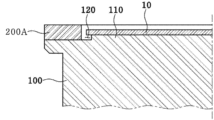
図2を参照すると、実施例による支持部材100は、装着部110及び陷沒部120を含むことができる。装着部110には前記基板10が装着されることができる。
Referring to FIG. 2, the
陷沒部120は前記装着部110と前記温度補償部材200Aの内側面との間に形成され、円形の基板10及びリング形の温度補償部材200Aと対応するようにリング形に形成されることができる。すなわち、陷沒部120は相対的に突出する装着部110を取り囲むように構成されることができる。
The recessed
図2を参照すると、前記陷沒部120は温度補償部材200Aの側面と装着部110の側面によって形成されることができる。
Referring to FIG. 2, the
このような構造により、前記基板10は、前記装着部110に装着されれば、側面と縁部の下面が露出されるように前記陷沒部120に配置されることができる。よって、前記基板10は側面が前記温度補償部材200Aから離隔するが隣接するように配置されることができる。
With this structure, when the
また、前記基板10の縁部の上面、側面及び下面が全部露出されるので、前記支持部材100に妨げられず、前記温度補償部材200Aから前記基板10の縁部に熱が効果的に伝逹されることができる。
Further, since the upper surface, side surface, and lower surface of the edge of the
したがって、前記基板10は、縁部の上面、側面及び下面が前記温度補償部材200Aから放出される熱によって加熱されるように構成され、これにより前記基板10の縁部は伝熱面積が増加して効果的に加熱されることができる。
Therefore, the
図3は図2の他の実施例を示した断面図である。図3に示したように、温度補償部材200Bは胴体部210B及びコーティング層220Bを含むことができる。
FIG. 3 is a sectional view showing another embodiment of FIG. 2. As shown in FIG. 3, the
胴体部210Bは前記支持部材100と同じ素材からなり、前記支持部材100と一体に形成されることができる。コーティング層220Bは前記胴体部210Bの表面にコーティングされ、前記胴体部210Bとは異なる素材からなることができる。
The
支持部材100と温度補償部材200が互いに異なる素材からなる場合、支持部材100と温度補償部材200の熱膨張率が互いに異なるので、基板支持装置が高温に加熱されれば、支持部材100と温度補償部材200の熱膨張率の差によって基板支持装置の変形、破損などが発生し得る。
When the
したがって、図3に示した実施例では、温度補償部材200Bの胴体部210Bを支持部材100と同じ素材からなることにより、前述した熱膨張率の差による基板支持装置の変形、破損などを効果的に抑制することができる。
Therefore, in the embodiment shown in FIG. 3, the
前記胴体部210Bは前記支持部材100と一体に形成されるので、図3に示したように、胴体部210Bの下面は支持部材100と一体に結合され、コーティング層220Bは前記胴体部210Bの両側面及び上面に配置されることができる。
Since the
また、前記コーティング層220Bは前記胴体部210Bより熱伝導率の高い素材からなることができる。一例として、前記コーティング層220Bはセラミック(ceramic)からなることもできる。
Further, the
一方、前記支持部材100は石英からなり、前記温度補償部材200Bは少なくとも一部が黒体からなることができる。すなわち、前記支持部材100及び前記胴体部210Bは石英からなり、前記コーティング層220Bは黒体に近い素材からなることができる。ここで、黒体に近い素材としては、炭化ケイ素(SiC)、ブラックセラミック(Black ceramic)、酸化アルミニウム(Al2O3)、グラファイト(graphite)及びブラック石英(Black Quartz)の少なくとも1種の物質を含むことができるが、これは例示的なものに過ぎない。
Meanwhile, the
また、前記支持部材100及び前記胴体部210Bは透光性石英からなり、前記コーティング層220Bは不透光性黒体からなることができる。
Further, the
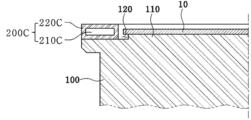
図4は図2のさらに他の実施例を示した断面図である。図4の実施例では、図3と同様に、温度補償部材200Cは、胴体部210C及び前記胴体部210Cの表面にコートされるコーティング層220Cを含む。
FIG. 4 is a sectional view showing still another embodiment of FIG. 2. In the embodiment of FIG. 4, similar to FIG. 3, the
ただ、図3の実施例とは違い、図4の実施例で、温度補償部材200Cは支持部材100とは別に製作されて支持部材100に結合することができる。ここで、結合器具を用いて前記温度補償部材200Cを前記支持部材100に結合することができる。
However, unlike the embodiment of FIG. 3, in the embodiment of FIG. 4, the
図4を参照すると、実施例で、前記コーティング層220Cは前記胴体部210Cの両側面、上面及び下面に配置されることができる。よって、前記温度補償部材200Cを断面で見たとき、前記コーティング層220Cは前記胴体部210Cを包むように構成されることができる。
Referring to FIG. 4, in an embodiment, the
図4に示した実施例では、図3の実施例と同様に、温度補償部材200Cの胴体部210Cを支持部材100と同じ素材からなることにより、前述した熱膨張率の差による基板支持装置の変形、破損などを効果的に抑制することができる。
In the embodiment shown in FIG. 4, similarly to the embodiment in FIG. 3, the body portion 210C of the
図5は図2のさらに他の実施例を示した断面図である。図5の実施例では、前記他の実施例と同様に、温度補償部材200Dは胴体部210D及び前記胴体部210Dの表面にコートされるコーティング層220Dを含み、胴体部210Dは支持部材100と一体に形成されることができる。
FIG. 5 is a sectional view showing still another embodiment of FIG. 2. In the embodiment of FIG. 5, as in the other embodiments, the
もちろん、前記胴体部210Dと前記コーティング層220Dは互いに異なる素材から形成され、前記コーティング層220Dは前記胴体部210Dより熱伝導率の高い素材からなることができる。以下では、図3及び図4の実施例で先に説明した内容と同じ内容についての重複説明は省略する。
Of course, the
図5を参照すると、前記コーティング層220Dの一部は前記陷沒部120の側面及び底面上に配置され、前記コーティング層220Dの一側は前記基板10の前記縁部の下面と接触するように構成されることができる。
Referring to FIG. 5, a portion of the
このような構造により、基板10の側面及び縁部の露出部位と対向するコーティング層220Dの表面積が増加し、よって、コーティング層220Dから基板10の側面及び縁部への熱伝逹量が増加するので、基板10の縁部に対する温度補償が効果的になされることができる。
Such a structure increases the surface area of the
また、前記コーティング層220Dの一側が前記基板10の縁部の下面と接触することにより、コーティング層220Dから基板10の縁部への熱伝導(thermal conduction)による熱伝逹がなされることができる。
In addition, since one side of the
このような熱伝導によってコーティング層220Dから基板10の縁部に活発に熱伝逹されるので、基板10の縁部に対する温度補償をより効果的になすことができる。
Since heat is actively transferred from the
図6は図2のさらに他の実施例を示した断面図である。実施例で、前記温度補償部材200Eと前記基板10は前記支持部材100の上面に配置されることができる。
FIG. 6 is a sectional view showing still another embodiment of FIG. 2. In example embodiments, the
もちろん、他の実施例と同様に、前記温度補償部材200Eと前記基板10の各側面は互いに対向して離隔するように配置されることができる。
Of course, as in other embodiments, the
ここで、前記温度補償部材200Eの下面と前記基板10の下面は上下方向に同じ高さに配置されることができる。すなわち、前記温度補償部材200Eと前記基板10は同一平面上に配置されることができる。ここで、前記同一平面は支持部材100の上面を意味し得る。
Here, the lower surface of the
したがって、実施例では、前述した他の実施例等とは違い、支持部材100の上面には突出した前記装着部110及び陷沒した前記陷沒部120が形成されなくてもよい。
Therefore, in this embodiment, unlike the other embodiments described above, the protruding mounting
図6の実施例では、このような構造により、支持部材100を容易に加工することができる。
In the embodiment of FIG. 6, such a structure allows the
また、温度補償部材200Eと基板10の下面が同一平面上に配置されるので、温度補償部材200Eと基板10の互いに対向する側面の面積を最大にすることができ、温度補償部材200Eから基板10の縁部に熱が効果的に伝逹されることができる。
Furthermore, since the lower surfaces of the
図7は図1の一実施例を適用した基板処理装置700を示した断面図である。前記基板処理装置700は、基板を処理するための反応空間を提供するチャンバー600と、チャンバー600の内部で基板10が装着される一つ又は二つ以上の支持部100と、前記一つ又は二つ以上の支持部100を収容し、中心軸を基準に前記チャンバー700内で移動可能にする支持部キャリア300と、前記支持部100に装着された基板10に対して工程ガスを噴射するガス噴射部500とを含むことができる。
FIG. 7 is a sectional view showing a
前記基板処理装置700は、前記支持部キャリア300の下部に、前記基板10を加熱するための加熱手段(図示せず)を含むことができる。前記加熱手段は、一例として光学式加熱手段であってもよい。前記光学式加熱手段から放出された光は前記支持部キャリア300を貫通してから前記支持部100を貫通して前記基板10を加熱することができる。ここで、前記支持部キャリア300は前記支持部100と同じ素材からなることができる。
The
一方、前記加熱手段は、光学式加熱手段の他に、誘導加熱方式の加熱手段又は抵抗加熱式加熱手段であってもよい。また、前記加熱手段は前記支持部キャリア300の内部に位置することもできる。
On the other hand, the heating means may be an induction heating type heating means or a resistance heating type heating means in addition to the optical heating means. Further, the heating means may be located inside the
一方、前記支持部100は前記支持部キャリア300から前記チャンバー600の上方にもっと突出することができる。前記支持部100に装着された基板10は前記支持部キャリア300の上面より高い位置に置かれることができる。また、前記支持部100は前記支持部キャリア300と結合されることができ、前記支持部キャリア300から分離されることもできる。前記支持部キャリア300に二つ以上の支持部100が結合される場合、前記支持部100は前記支持部キャリア300に着脱可能に結合されることもできる。
Meanwhile, the
前記基板処理装置700において前記支持部100が前記支持部キャリア300の上面から突出する場合、前記支持部100の上面の縁部と側面は反応空間に露出され、前記支持部100の基板が装着された部分より熱損失が増加することになる。前記支持部100に装着された基板の縁部は基板の中心部より熱損失が相対的に大きくなることができる。したがって、前記支持部100に図1~図6で説明した温度補償部材200が取り付けられれば、前記温度補償部材200から放出される熱によって前記基板10の縁部の熱損失が補償され、前記基板の温度が均一に維持されることができる。また、条件によっては、前記基板の縁部の温度をもっと高く維持することができる。
In the
一方、図3~図6を参照して説明した基板支持装置の構造による他の効果は図1及び図2を参照して前述した効果と同一又は類似であるので、それについての重複説明は省略する。 On the other hand, other effects of the structure of the substrate support device described with reference to FIGS. 3 to 6 are the same or similar to the effects described above with reference to FIGS. 1 and 2, so a redundant explanation thereof will be omitted. do.
実施例に基づいて前述したように幾つかのもののみを記述したが、その外にも多様な形態の実施が可能である。前述した実施例の技術的内容は互いに両立できない技術ではない限り、多様な形態に組み合わせられることができ、これによって新しい実施形態に具現することもできる。 Although only some of the embodiments have been described above based on the embodiments, various other embodiments are possible. The technical contents of the embodiments described above can be combined in various forms unless they are incompatible with each other, and thus can be implemented in new embodiments.
発明の実施のための形態は前述した“発明を実施するための形態”で充分に説明した。 The mode for carrying out the invention has been fully explained in the above-mentioned "Detailed Description of the Invention".
本発明は基板支持装置に関するものである。よって、本発明は産業上利用可能性がある。 The present invention relates to a substrate support device. Therefore, the present invention has industrial applicability.
Claims (12)
前記支持部材の縁端に配置される温度補償部材と、
を含み、
前記温度補償部材は、
前記支持部材と同じ素材からなる胴体部と、
前記胴体部の表面にコーティング層、前記支持部材と異なる素材から形成されるコーティング層を含み、
前記支持部材は透光性素材からなり、前記温度補償部材は不透光性素材からなり、
前記支持部材は、
前記基板が装着される装着部であって、前記支持部材の上面から突出している、装着部と、
前記装着部と前記温度補償部材の内側面との間に形成されるリング形の陷沒部と、
を含み、
前記基板は側面及び縁部の下面が露出されるように前記陷沒部に配置され、
前記コーティング層は前記胴体部より熱伝導率が高い材料からなり、前記胴体部の両側面及び上面に配置される、ことを特徴とする基板支持装置。 a support member that supports the substrate;
a temperature compensation member disposed at an edge of the support member;
including;
The temperature compensation member is
a body portion made of the same material as the support member;
a coating layer on the surface of the body, a coating layer formed from a material different from that of the support member;
The support member is made of a translucent material, the temperature compensation member is made of a non-transparent material,
The support member is
a mounting portion on which the board is mounted, the mounting portion protruding from the upper surface of the support member;
a ring-shaped groove formed between the mounting portion and the inner surface of the temperature compensating member;
including;
The substrate is disposed in the recess so that side surfaces and a lower surface of the edge are exposed;
The substrate supporting device according to claim 1, wherein the coating layer is made of a material having higher thermal conductivity than the body, and is disposed on both sides and an upper surface of the body.
前記コーティング層は黒体からなることを特徴とする、請求項1に記載の基板支持装置。 The support member and the body portion are made of quartz,
The substrate support device according to claim 1 , wherein the coating layer is made of a black body.
前記支持部材の縁端に配置され、前記支持部材と異なる素材からなる温度補償部材と、を含み、
前記支持部材は、
前記基板が装着される装着部であって、前記支持部材の上面から突出している、装着部と、
前記装着部と前記温度補償部材の内側面との間に形成されるリング形の陷沒部と、
を含み、
前記温度補償部材は、
前記支持部材と同じ素材からなり、前記支持部材と一体に形成される胴体部と、
前記胴体部の表面にコーティングされ、前記胴体部と異なる素材からなるコーティング層と、を含み、
前記温度補償部材の表面は洗浄ガスに対して耐食性を有する素材からなり、
前記基板は側面と縁部の下面が露出されるように前記陷沒部に配置され、前記コーティング層は前記胴体部より熱伝導率が高い材料からなり、前記コーティング層の一部は前記陷沒部の側面及び底面上に配置され、前記コーティング層の他の部分は前記基板の縁部の下面と接触するように構成され、前記コーティング層から放出される熱によって加熱されるように構成されることを特徴とする基板支持装置。 a support member that supports the substrate;
a temperature compensating member disposed at an edge of the supporting member and made of a different material from the supporting member;
The support member is
a mounting portion on which the board is mounted, the mounting portion protruding from the upper surface of the support member;
a ring-shaped groove formed between the mounting portion and the inner surface of the temperature compensating member;
including;
The temperature compensation member is
a body portion made of the same material as the support member and integrally formed with the support member;
a coating layer coated on the surface of the body part and made of a different material from the body part,
The surface of the temperature compensating member is made of a material that has corrosion resistance against cleaning gas,
The substrate is disposed in the recess so that side surfaces and lower surfaces of the edges are exposed, the coating layer is made of a material having higher thermal conductivity than the body, and a portion of the coating layer is disposed in the recess. another portion of the coating layer is configured to contact a lower surface of the edge of the substrate and is configured to be heated by heat emitted from the coating layer . A substrate support device characterized by:
胴体部の上面と側面の上に形成された第1コーティング層と、
前記陷沒部との下面と側面の上に形成された第2コーティング層と、
を含み、
前記第2コーティング層と前記基板の縁部は垂直方向に互いに向かい合って配置されることを特徴とする、請求項8に記載の基板支持装置。 The coating layer is
a first coating layer formed on the top and side surfaces of the fuselage;
a second coating layer formed on the bottom and side surfaces of the slit;
including;
9. The substrate supporting apparatus of claim 8 , wherein the second coating layer and the edge of the substrate are vertically disposed opposite each other.
Applications Claiming Priority (3)
| Application Number | Priority Date | Filing Date | Title |
|---|---|---|---|
| KR20170079595 | 2017-06-23 | ||
| KR10-2017-0079595 | 2017-06-23 | ||
| PCT/KR2018/007186 WO2018236201A1 (en) | 2017-06-23 | 2018-06-25 | Substrate supporting apparatus |
Publications (3)
| Publication Number | Publication Date |
|---|---|
| JP2020524892A JP2020524892A (en) | 2020-08-20 |
| JP2020524892A5 JP2020524892A5 (en) | 2021-08-05 |
| JP7345397B2 true JP7345397B2 (en) | 2023-09-15 |
Family
ID=64737692
Family Applications (1)
| Application Number | Title | Priority Date | Filing Date |
|---|---|---|---|
| JP2019559270A Active JP7345397B2 (en) | 2017-06-23 | 2018-06-25 | Board support device |
Country Status (6)
| Country | Link |
|---|---|
| US (1) | US11417562B2 (en) |
| JP (1) | JP7345397B2 (en) |
| KR (1) | KR102147326B1 (en) |
| CN (1) | CN110622291B (en) |
| TW (1) | TWI793137B (en) |
| WO (1) | WO2018236201A1 (en) |
Families Citing this family (17)
| Publication number | Priority date | Publication date | Assignee | Title |
|---|---|---|---|---|
| US6795998B1 (en) * | 2000-07-24 | 2004-09-28 | Illinois Tool Works, Inc. | Swab with pull-truded tip |
| KR100766017B1 (en) * | 2004-09-23 | 2007-10-10 | 유계춘 | Styropol tube |
| KR100780703B1 (en) * | 2005-04-11 | 2007-11-30 | 전남대학교산학협력단 | Continuous Extrusion Extraction Equipment |
| KR100723262B1 (en) * | 2005-06-14 | 2007-05-31 | 오현오 | Portable Device to Supply Warm Water |
| KR100743596B1 (en) * | 2005-08-16 | 2007-07-27 | 주식회사 협성히스코 | pressure gauge |
| KR100720002B1 (en) * | 2006-06-09 | 2007-05-21 | 조현찬 | Jewelry printed with metal patterns and manufacturing method thereof |
| KR100712227B1 (en) * | 2006-06-15 | 2007-04-27 | 이운갑 | Black rice pounded by using a rice pudding machine and its polishing machine |
| KR100764123B1 (en) * | 2006-07-20 | 2007-10-09 | 광신금속(주) | Outer barbed barbed wire and wheeled barbed wire using the same |
| KR100746236B1 (en) * | 2006-10-02 | 2007-08-06 | 정광용 | Natural parasol consisting of branches, leaves, berries and flowers forming a natural shade |
| KR100741292B1 (en) * | 2007-02-16 | 2007-07-23 | 종 완 김 | Shoes with various shapes by shoelaces |
| KR100733029B1 (en) * | 2007-02-27 | 2007-06-28 | 주식회사 누리플랜 | Street lamp |
| KR100727289B1 (en) * | 2007-02-27 | 2007-06-13 | 주식회사삼영이앤티 | Tension Control Device of Sludge Collector |
| KR100746353B1 (en) * | 2007-05-21 | 2007-08-03 | (주)맥스미디어 | Moisture-proof speaker assembly |
| KR100778779B1 (en) * | 2007-06-22 | 2007-11-27 | 통명석재 주식회사 | Scratch Device for Stone |
| DE102020110570A1 (en) * | 2020-04-17 | 2021-10-21 | Aixtron Se | CVD process and CVD reactor with bodies that can be exchanged with the substrate and exchange heat |
| US20240247404A1 (en) * | 2023-01-25 | 2024-07-25 | Applied Materials, Inc. | Pre-heat rings and processing chambers including black quartz, and related methods |
| CN117594489A (en) * | 2023-11-21 | 2024-02-23 | 深圳市华盈微技术有限公司 | Uniform temperature plate assembly, semiconductor wafer baking equipment and wafer baking heat radiation compensation method |
Citations (5)
| Publication number | Priority date | Publication date | Assignee | Title |
|---|---|---|---|---|
| JP2001189375A (en) | 1999-10-18 | 2001-07-10 | Hitachi Kokusai Electric Inc | Substrate processing apparatus and method of manufacturing semiconductor device |
| JP2005142529A (en) | 2003-10-16 | 2005-06-02 | Tokyo Electron Ltd | Deposition equipment |
| JP2010225645A (en) | 2009-03-19 | 2010-10-07 | Dainippon Screen Mfg Co Ltd | Heat treatment apparatus |
| JP2012134504A (en) | 2010-12-23 | 2012-07-12 | Samsung Led Co Ltd | Susceptor for chemical vapor deposition apparatus, chemical vapor deposition apparatus, and heating method for substrate using chemical vapor deposition apparatus |
| JP2016530730A (en) | 2013-09-16 | 2016-09-29 | アプライド マテリアルズ インコーポレイテッドApplied Materials,Incorporated | Epi preheating ring |
Family Cites Families (14)
| Publication number | Priority date | Publication date | Assignee | Title |
|---|---|---|---|---|
| JPH01291421A (en) * | 1988-05-19 | 1989-11-24 | Toshiba Corp | Vapor growth apparatus |
| US6589352B1 (en) * | 1999-12-10 | 2003-07-08 | Applied Materials, Inc. | Self aligning non contact shadow ring process kit |
| KR20030059745A (en) | 2002-01-04 | 2003-07-10 | 주성엔지니어링(주) | Wafer temperature compensator using reflector |
| DE10261362B8 (en) * | 2002-12-30 | 2008-08-28 | Osram Opto Semiconductors Gmbh | Substrate holder |
| US6888104B1 (en) * | 2004-02-05 | 2005-05-03 | Applied Materials, Inc. | Thermally matched support ring for substrate processing chamber |
| CN101587881A (en) * | 2008-05-19 | 2009-11-25 | 海华科技股份有限公司 | Module integrated circuit packaging structure with temperature compensation control quartz oscillator |
| JP2011018772A (en) * | 2009-07-09 | 2011-01-27 | Nippon Steel Corp | Susceptor for silicon carbide single crystal film forming device |
| KR101002748B1 (en) * | 2009-11-17 | 2010-12-21 | (주)앤피에스 | Susceptor unit and substrate heat treatment apparatus having the same |
| US8979087B2 (en) | 2011-07-29 | 2015-03-17 | Applied Materials, Inc. | Substrate supporting edge ring with coating for improved soak performance |
| JP5965122B2 (en) | 2011-09-26 | 2016-08-03 | 株式会社Screenホールディングス | Heat treatment method and heat treatment apparatus |
| US9403251B2 (en) * | 2012-10-17 | 2016-08-02 | Applied Materials, Inc. | Minimal contact edge ring for rapid thermal processing |
| CN103074673A (en) | 2012-12-26 | 2013-05-01 | 光达光电设备科技(嘉兴)有限公司 | Substrate supporting structure and deposition device |
| JP6321509B2 (en) | 2014-09-24 | 2018-05-09 | 東京エレクトロン株式会社 | Substrate processing apparatus and substrate mounting unit manufacturing method |
| JP6602145B2 (en) * | 2015-10-13 | 2019-11-06 | 大陽日酸株式会社 | Substrate mounting table and vapor phase growth apparatus |
-
2018
- 2018-06-25 WO PCT/KR2018/007186 patent/WO2018236201A1/en not_active Ceased
- 2018-06-25 US US16/613,115 patent/US11417562B2/en active Active
- 2018-06-25 TW TW107121769A patent/TWI793137B/en active
- 2018-06-25 JP JP2019559270A patent/JP7345397B2/en active Active
- 2018-06-25 CN CN201880029938.2A patent/CN110622291B/en active Active
- 2018-06-25 KR KR1020180073025A patent/KR102147326B1/en active Active
Patent Citations (5)
| Publication number | Priority date | Publication date | Assignee | Title |
|---|---|---|---|---|
| JP2001189375A (en) | 1999-10-18 | 2001-07-10 | Hitachi Kokusai Electric Inc | Substrate processing apparatus and method of manufacturing semiconductor device |
| JP2005142529A (en) | 2003-10-16 | 2005-06-02 | Tokyo Electron Ltd | Deposition equipment |
| JP2010225645A (en) | 2009-03-19 | 2010-10-07 | Dainippon Screen Mfg Co Ltd | Heat treatment apparatus |
| JP2012134504A (en) | 2010-12-23 | 2012-07-12 | Samsung Led Co Ltd | Susceptor for chemical vapor deposition apparatus, chemical vapor deposition apparatus, and heating method for substrate using chemical vapor deposition apparatus |
| JP2016530730A (en) | 2013-09-16 | 2016-09-29 | アプライド マテリアルズ インコーポレイテッドApplied Materials,Incorporated | Epi preheating ring |
Also Published As
| Publication number | Publication date |
|---|---|
| US20210082738A1 (en) | 2021-03-18 |
| WO2018236201A1 (en) | 2018-12-27 |
| US11417562B2 (en) | 2022-08-16 |
| JP2020524892A (en) | 2020-08-20 |
| KR102147326B1 (en) | 2020-08-24 |
| CN110622291A (en) | 2019-12-27 |
| TWI793137B (en) | 2023-02-21 |
| KR20190000850A (en) | 2019-01-03 |
| CN110622291B (en) | 2024-05-14 |
| TW201906069A (en) | 2019-02-01 |
Similar Documents
| Publication | Publication Date | Title |
|---|---|---|
| JP7345397B2 (en) | Board support device | |
| JP5707766B2 (en) | Susceptor and semiconductor manufacturing equipment | |
| TWI570258B (en) | Gas distribution showerhead with high emissivity surface | |
| JP5748699B2 (en) | Apparatus and method for depositing a layer of material | |
| US9396909B2 (en) | Gas dispersion apparatus | |
| TWI875850B (en) | Process kit for improving edge film thickness uniformity on a substrate | |
| US20160068996A1 (en) | Susceptor and pre-heat ring for thermal processing of substrates | |
| TWI778370B (en) | Heat shield assembly for an epitaxy chamber | |
| KR20040096785A (en) | Anodized substrate support | |
| WO2004090960A1 (en) | Loading table and heat treating apparatus having the loading table | |
| US9677177B2 (en) | Substrate support with quadrants | |
| KR20030097861A (en) | Assembly comprising heat distributing plate and edge support | |
| KR102871352B1 (en) | Steam transmission methods and devices | |
| TWM545140U (en) | Device for holding a substrate in a process chamber of a CVD or PVD reactor | |
| KR20130073407A (en) | High temperature evaporation having outer heating container | |
| JP5440589B2 (en) | Vapor growth apparatus and epitaxial wafer manufacturing method | |
| CN104934345A (en) | Plasma device | |
| KR100830237B1 (en) | Susceptor structures in large area substrate processing systems | |
| WO2020033097A1 (en) | Liner for processing chamber | |
| KR20120038287A (en) | Susceptor | |
| EP4372122A2 (en) | Deposition source and deposition apparatus including the same | |
| KR20080114284A (en) | Chemical vapor deposition apparatus with improved heating support member | |
| TW202320214A (en) | Substrate support | |
| TW202314034A (en) | Chemical vapor deposition system and assembly thereof | |
| KR20020084478A (en) | Apparatus for depositing in semiconductor process |
Legal Events
| Date | Code | Title | Description |
|---|---|---|---|
| A521 | Request for written amendment filed |
Free format text: JAPANESE INTERMEDIATE CODE: A523 Effective date: 20210618 |
|
| A621 | Written request for application examination |
Free format text: JAPANESE INTERMEDIATE CODE: A621 Effective date: 20210618 |
|
| A977 | Report on retrieval |
Free format text: JAPANESE INTERMEDIATE CODE: A971007 Effective date: 20220712 |
|
| A131 | Notification of reasons for refusal |
Free format text: JAPANESE INTERMEDIATE CODE: A131 Effective date: 20220726 |
|
| A521 | Request for written amendment filed |
Free format text: JAPANESE INTERMEDIATE CODE: A523 Effective date: 20221020 |
|
| A131 | Notification of reasons for refusal |
Free format text: JAPANESE INTERMEDIATE CODE: A131 Effective date: 20230214 |
|
| A521 | Request for written amendment filed |
Free format text: JAPANESE INTERMEDIATE CODE: A523 Effective date: 20230511 |
|
| TRDD | Decision of grant or rejection written | ||
| A01 | Written decision to grant a patent or to grant a registration (utility model) |
Free format text: JAPANESE INTERMEDIATE CODE: A01 Effective date: 20230808 |
|
| A61 | First payment of annual fees (during grant procedure) |
Free format text: JAPANESE INTERMEDIATE CODE: A61 Effective date: 20230905 |
|
| R150 | Certificate of patent or registration of utility model |
Ref document number: 7345397 Country of ref document: JP Free format text: JAPANESE INTERMEDIATE CODE: R150 |