JP7340356B2 - game machine - Google Patents
game machine Download PDFInfo
- Publication number
- JP7340356B2 JP7340356B2 JP2019104134A JP2019104134A JP7340356B2 JP 7340356 B2 JP7340356 B2 JP 7340356B2 JP 2019104134 A JP2019104134 A JP 2019104134A JP 2019104134 A JP2019104134 A JP 2019104134A JP 7340356 B2 JP7340356 B2 JP 7340356B2
- Authority
- JP
- Japan
- Prior art keywords
- backup
- game
- performance
- data
- executed
- Prior art date
- Legal status (The legal status is an assumption and is not a legal conclusion. Google has not performed a legal analysis and makes no representation as to the accuracy of the status listed.)
- Active
Links
Images


Classifications
-
- Y—GENERAL TAGGING OF NEW TECHNOLOGICAL DEVELOPMENTS; GENERAL TAGGING OF CROSS-SECTIONAL TECHNOLOGIES SPANNING OVER SEVERAL SECTIONS OF THE IPC; TECHNICAL SUBJECTS COVERED BY FORMER USPC CROSS-REFERENCE ART COLLECTIONS [XRACs] AND DIGESTS
- Y02—TECHNOLOGIES OR APPLICATIONS FOR MITIGATION OR ADAPTATION AGAINST CLIMATE CHANGE
- Y02E—REDUCTION OF GREENHOUSE GAS [GHG] EMISSIONS, RELATED TO ENERGY GENERATION, TRANSMISSION OR DISTRIBUTION
- Y02E60/00—Enabling technologies; Technologies with a potential or indirect contribution to GHG emissions mitigation
- Y02E60/10—Energy storage using batteries
Description
本発明は、パチンコ遊技機等の遊技を行うことが可能な遊技機に関する。 The present invention relates to a gaming machine that can play games such as a pachinko gaming machine.
パチンコ遊技機等の遊技機において、バックアップ対象データの分割回数を設定して、所定の割込回数にてバックアップ処理を完了させる技術が提案されている(例えば特許文献1)。 In gaming machines such as pachinko gaming machines, a technique has been proposed in which the number of times data to be backed up is divided is set and the backup processing is completed at a predetermined number of interruptions (for example, Patent Document 1).
上記特許文献1に記載の技術によると、データ容量の増大に伴い処理負担が過大となり、不具合が生じるおそれがあった。
According to the technique described in
この発明は、上記実状に鑑みてなされたものであり、情報を適切に記憶可能な遊技機の提供を目的とする。 This invention has been made in view of the above-mentioned circumstances, and aims to provide a gaming machine that can appropriately store information.
(A)上記目的を達成するために、本発明に係る遊技機は、
遊技を行うことが可能な遊技機であって、
制御手段により書込可能な記憶手段と、
遊技または演出の進行に伴う事象の発生に対応して、前記記憶手段に書き込む情報を記憶可能な一時記憶手段と、
を備え、
前記制御手段は、
書込条件の成立に基づいて、前記一時記憶手段の記憶内容を前記記憶手段に書き込む特定書込処理を実行可能であり、
前記特定書込処理として、
遊技または演出の進行に伴う事象の発生に対応して、前記記憶手段に記憶させる対象範囲に含まれる第1情報と、1の書込条件が成立する前に前記記憶手段が記憶している第2情報とで、差分情報を特定して前記一時記憶手段に記憶する一時記憶処理と、
前記一時記憶手段に記憶された差分情報を前記記憶手段に書き込む差分書込処理と、
を含む処理を実行可能であり、
前記特定書込処理を、所定時間が経過するごとに行われるタイマ割込み処理内で実行可能であり、
前記タイマ割込み処理内において、演出に係る制御処理が行われた後、最後の処理として前記特定書込処理を実行可能であり、
電力供給が開始されたときに、前記記憶手段の記憶情報を前記一時記憶手段に読み出して復旧可能であり、
前記記憶手段は、同一の情報を複数の記憶領域に記憶可能である。
このような構成によれば、情報を適切に記憶可能となる。
(1)上記目的を達成するために、他の遊技機は、遊技を行うことが可能な遊技機(例えばパチンコ遊技機1など)であって、制御手段(例えば演出制御用マイクロコンピュータ19AK120のCPU19AK131など)により書込可能な記憶手段(例えばバックアップデータメモリ19AK210A~210Dのバックアップ記憶部19AKA1など)と、前記記憶手段に書き込む情報を記憶可能な一時記憶手段(例えば外部RAM19AK122や内部RAM19AK133のバックアップデータバッファ19AKB1など)と、を備え、前記制御手段は、書込条件の成立に基づいて、前記一時記憶手段の記憶内容を前記記憶手段に書き込む特定書込処理(例えばステップ19AKS79の演出制御中バックアップ処理など)を実行可能であり、前記特定書込処理として、前記記憶手段に記憶させる対象範囲に含まれる第1情報と、1の書込条件が成立する前に前記記憶手段が記憶している第2情報とで、差分情報を特定して前記一時記憶手段に記憶する一時記憶処理(例えばステップ19AKS103の差分スタック更新処理とステップ19AKS105の書込バッファ更新処理など)と、前記一時記憶手段に記憶された差分情報を前記記憶手段に書き込む差分書込処理(例えばステップ19AKS108のバックアップデータ書込処理など)と、を含む処理を実行可能であり、電力供給が開始されたときに、前記記憶手段の記憶情報を前記一時記憶手段に読み出して復旧可能(例えばステップ19AKS23の電源投入時情報処理により対象データ記憶部19AKM1の記憶内容を復旧可能など)である。
このような構成によれば、情報を適切に記憶可能となる。
(A) In order to achieve the above object, the gaming machine according to the present invention:
A gaming machine capable of playing games,
storage means writable by the control means;
temporary storage means capable of storing information to be written in the storage means in response to the occurrence of an event accompanying the progress of a game or performance;
Equipped with
The control means includes:
A specific write process for writing the memory contents of the temporary storage means into the storage means can be executed based on the establishment of a write condition,
As the specific write process,
In response to the occurrence of an event accompanying the progress of a game or performance, first information included in the target range to be stored in the storage means, and first information stored in the storage means before the first writing condition is satisfied. 2 information, a temporary storage process of specifying the difference information and storing it in the temporary storage means;
a difference writing process of writing the difference information stored in the temporary storage means into the storage means;
It is possible to perform processing including
The specific write process can be executed within a timer interrupt process that is performed every time a predetermined time elapses,
Within the timer interrupt process, after the control process related to the performance is performed, the specific write process can be executed as the last process,
When power supply is started, the information stored in the storage means can be read out to the temporary storage means for recovery;
The storage means can store the same information in a plurality of storage areas.
According to such a configuration, information can be stored appropriately.
(1) In order to achieve the above object, the other gaming machine is a gaming machine that can play games (for example, Pachinko
According to such a configuration, information can be stored appropriately.
(2)上記(1)の遊技機において、前記差分書込処理の実行中には、前記一時記憶手段に記憶する差分情報の更新を禁止(例えばステップ19AKS106による禁止設定など)してもよい。
このような構成においては、情報を適切に記憶可能となる。
(2) In the gaming machine of (1) above, updating of the difference information stored in the temporary storage means may be prohibited (for example, prohibited setting by step 19AKS106) while the difference writing process is being executed.
In such a configuration, information can be stored appropriately.
(3)上記(1)または(2)の遊技機において、前記一時記憶手段に記憶する差分情報の更新が行われない期間において、前記差分書込処理を実行(例えばステップ19AKS112による許可設定の後、ステップ19AKS102~19AKS105を実行など)してもよい。
このような構成においては、情報を適切に記憶可能となる。
(3) In the gaming machine of (1) or (2) above, the difference writing process is executed during a period in which the difference information stored in the temporary storage means is not updated (for example, after permission setting in step 19AKS112) , execute steps 19AKS102 to 19AKS105, etc.).
In such a configuration, information can be stored appropriately.
(4)上記(1)から(3)のいずれかの遊技機において、前記一時記憶手段は、前記記憶手段に未だ書き込まれない差分情報を記憶可能な第1記憶領域(例えば差分スタック20AKB11など)と、前記記憶手段に書き込まれる差分情報を記憶可能な第2記憶領域(例えば書込バッファ20AKB12など)と、を含むようにしてもよい。
このような構成においては、情報を適切に記憶可能となる。
(4) In the gaming machine according to any one of (1) to (3) above, the temporary storage means is a first storage area (for example, a difference stack 20AKB11, etc.) capable of storing difference information that has not yet been written to the storage means. and a second storage area (for example, the write buffer 20AKB12) capable of storing the difference information written in the storage means.
In such a configuration, information can be stored appropriately.
(5)上記(1)から(4)のいずれかの遊技機において、前記記憶手段は、同一の情報を複数の記憶領域(例えばバックアップ記憶部41AKA1~41AKA3など)に記憶可能であり、前記差分書込処理により前記複数の記憶領域に対する書き込みが完了するまで、前記一時記憶手段に記憶する差分情報の更新を禁止してもよい。
このような構成においては、情報を適切に記憶可能となる。
(5) In the gaming machine according to any one of (1) to (4) above, the storage means is capable of storing the same information in a plurality of storage areas (for example, backup storage sections 41AKA1 to 41AKA3, etc.), and Updating of the difference information stored in the temporary storage unit may be prohibited until writing to the plurality of storage areas is completed by a write process.
In such a configuration, information can be stored appropriately.
(基本説明)
まず、パチンコ遊技機1の基本的な構成及び制御(一般的なパチンコ遊技機の構成及び制御でもある。)について説明する。
(Basic explanation)
First, the basic configuration and control of the pachinko gaming machine 1 (also the configuration and control of a general pachinko gaming machine) will be explained.
(パチンコ遊技機1の構成等)
図1は、パチンコ遊技機1の正面図であり、主要部材の配置レイアウトを示す。パチンコ遊技機(遊技機)1は、大別して、遊技盤面を構成する遊技盤(ゲージ盤)2と、遊技盤2を支持固定する遊技機用枠(台枠)3とから構成されている。遊技盤2には、遊技領域が形成され、この遊技領域には、遊技媒体としての遊技球が、所定の打球発射装置から発射されて打ち込まれる。
(Configuration of
FIG. 1 is a front view of a
なお、特別図柄の「可変表示」とは、例えば、複数種類の特別図柄を変動可能に表示することである(後述の他の図柄についても同じ)。変動としては、複数の図柄の更新表示、複数の図柄のスクロール表示、1以上の図柄の変形、1以上の図柄の拡大/縮小などがある。特別図柄や後述の普通図柄の変動では、複数種類の特別図柄又は普通図柄が更新表示される。後述の飾り図柄の変動では、複数種類の飾り図柄がスクロール表示又は更新表示されたり、1以上の飾り図柄が変形や拡大/縮小されたりする。なお、変動には、ある図柄を点滅表示する態様も含まれる。可変表示の最後には、表示結果として所定の特別図柄が停止表示(導出または導出表示などともいう)される(後述の他の図柄の可変表示についても同じ)。なお、可変表示を変動表示、変動と表現する場合がある。 Note that "variable display" of special symbols means, for example, displaying a plurality of types of special symbols in a variable manner (the same applies to other symbols described later). The variations include updated display of a plurality of symbols, scroll display of a plurality of symbols, deformation of one or more symbols, enlargement/reduction of one or more symbols, and the like. In the variation of special symbols and normal symbols described below, a plurality of types of special symbols or normal symbols are updated and displayed. In the variation of decorative patterns described below, a plurality of types of decorative patterns are scrolled or updated, or one or more decorative patterns are deformed or enlarged/reduced. Note that the variation also includes a mode in which a certain symbol is displayed blinking. At the end of the variable display, a predetermined special symbol is stopped and displayed (also referred to as derivation or derivation display) as a display result (the same applies to the variable display of other symbols described later). Note that the variable display may be expressed as a variable display or fluctuation.
なお、第1特別図柄表示装置4Aにおいて可変表示される特別図柄を「第1特図」ともいい、第2特別図柄表示装置4Bにおいて可変表示される特別図柄を「第2特図」ともいう。また、第1特図を用いた特図ゲームを「第1特図ゲーム」といい、第2特図を用いた特図ゲームを「第2特図ゲーム」ともいう。なお、特別図柄の可変表示を行う特別図柄表示装置は1種類であってもよい。
The special symbol variably displayed on the first special
遊技盤2における遊技領域の中央付近には画像表示装置5が設けられている。画像表示装置5は、例えばLCD(液晶表示装置)や有機EL(Electro Luminescence)等から構成され、各種の演出画像を表示する。画像表示装置5は、プロジェクタおよびスクリーンから構成されていてもよい。画像表示装置5には、各種の演出画像が表示される。
An
例えば、画像表示装置5の画面上では、第1特図ゲームや第2特図ゲームと同期して、特別図柄とは異なる複数種類の装飾識別情報としての飾り図柄(数字などを示す図柄など)の可変表示が行われる。ここでは、第1特図ゲームまたは第2特図ゲームに同期して、「左」、「中」、「右」の各飾り図柄表示エリア5L、5C、5Rにおいて飾り図柄が可変表示(例えば上下方向のスクロール表示や更新表示)される。なお、同期して実行される特図ゲームおよび飾り図柄の可変表示を総称して単に可変表示ともいう。
For example, on the screen of the
画像表示装置5の画面上には、実行が保留されている可変表示に対応する保留表示や、実行中の可変表示に対応するアクティブ表示を表示するための表示エリアが設けられていてもよい。保留表示およびアクティブ表示を総称して可変表示に対応する可変表示対応表示ともいう。
A display area may be provided on the screen of the
保留されている可変表示の数は保留記憶数ともいう。第1特図ゲームに対応する保留記憶数を第1保留記憶数、第2特図ゲームに対応する保留記憶数を第2保留記憶数ともいう。第1保留記憶数と第2保留記憶数との合計を合計保留記憶数ともいう。 The number of pending variable displays is also called the number of pending memories. The number of pending memories corresponding to the first special figure game is also referred to as the first number of pending memories, and the number of pending memories corresponding to the second special figure game is also referred to as the second number of pending memories. The sum of the first number of pending memories and the second number of pending memories is also referred to as the total number of pending memories.
遊技盤2の所定位置には、複数のLEDを含んで構成された第1保留表示器25Aと第2保留表示器25Bとが設けられている。第1保留表示器25Aは、LEDの点灯個数によって、第1保留記憶数を表示する。第2保留表示器25Bは、LEDの点灯個数によって、第2保留記憶数を表示する。
A
画像表示装置5の下方には、入賞球装置6Aと、可変入賞球装置6Bとが設けられている。
Below the
入賞球装置6Aは、例えば所定の玉受部材によって常に遊技球が進入可能な一定の開放状態に保たれる第1始動入賞口を形成する。第1始動入賞口に遊技球が進入したときには、所定個(例えば3個)の賞球が払い出されるとともに、第1特図ゲームが開始され得る。
The winning
可変入賞球装置6B(普通電動役物)は、ソレノイド81(図3参照)によって閉鎖状態と開放状態とに変化する第2始動入賞口を形成する。可変入賞球装置6Bは、例えば、一対の可動翼片を有する電動チューリップ型役物を備え、ソレノイド81がオフ状態であるときに可動翼片が垂直位置となることにより、当該可動翼片の先端が入賞球装置6Aに近接し、第2始動入賞口に遊技球が進入しない閉鎖状態になる(第2始動入賞口が閉鎖状態になるともいう。)。その一方で、可変入賞球装置6Bは、ソレノイド81がオン状態であるときに可動翼片が傾動位置となることにより、第2始動入賞口に遊技球が進入できる開放状態になる(第2始動入賞口が開放状態になるともいう。)。第2始動入賞口に遊技球が進入したときには、所定個(例えば3個)の賞球が払い出されるとともに、第2特図ゲームが開始され得る。なお、可変入賞球装置6Bは、閉鎖状態と開放状態とに変化するものであればよく、電動チューリップ型役物を備えるものに限定されない。
The variable prize winning
遊技盤2の所定位置(図1に示す例では、遊技領域の左右下方4箇所)には、所定の玉受部材によって常に一定の開放状態に保たれる一般入賞口10が設けられる。この場合には、一般入賞口10のいずれかに進入したときには、所定個数(例えば10個)の遊技球が賞球として払い出される。
At predetermined positions on the game board 2 (in the example shown in FIG. 1, four locations on the left and right lower sides of the game area), general winning
入賞球装置6Aと可変入賞球装置6Bの下方には、大入賞口を有する特別可変入賞球装置7が設けられている。特別可変入賞球装置7は、ソレノイド82(図3参照)によって開閉駆動される大入賞口扉を備え、その大入賞口扉によって開放状態と閉鎖状態とに変化する特定領域としての大入賞口を形成する。
A special variable winning
一例として、特別可変入賞球装置7では、大入賞口扉用(特別電動役物用)のソレノイド82がオフ状態であるときに大入賞口扉が大入賞口を閉鎖状態として、遊技球が大入賞口に進入(通過)できなくなる。その一方で、特別可変入賞球装置7では、大入賞口扉用のソレノイド82がオン状態であるときに大入賞口扉が大入賞口を開放状態として、遊技球が大入賞口に進入しやすくなる。
As an example, in the special variable winning
大入賞口に遊技球が進入したときには、所定個数(例えば14個)の遊技球が賞球として払い出される。大入賞口に遊技球が進入したときには、例えば第1始動入賞口や第2始動入賞口および一般入賞口10に遊技球が進入したときよりも多くの賞球が払い出される。
When game balls enter the grand prize opening, a predetermined number (for example, 14) of game balls are paid out as prize balls. When the game ball enters the big winning hole, more prize balls are paid out than when the game ball enters the first starting winning hole, the second starting winning hole, and the general winning
一般入賞口10を含む各入賞口に遊技球が進入することを「入賞」ともいう。特に、始動口(第1始動入賞口、第2始動入賞口)への入賞を始動入賞ともいう。
Entering the game ball into each winning hole including the general winning
遊技盤2の所定位置(図1に示す例では、遊技領域の左側方)には、普通図柄表示器20が設けられている。一例として、普通図柄表示器20は、7セグメントのLEDなどからなり、特別図柄とは異なる複数種類の普通識別情報としての普通図柄の可変表示を行う。普通図柄は、「0」~「9」を示す数字や「-」などの点灯パターンなどにより表される。普通図柄には、LEDを全て消灯したパターンが含まれてもよい。このような普通図柄の可変表示は、普図ゲームともいう。
A
画像表示装置5の左方には、遊技球が通過可能な通過ゲート41が設けられている。遊技球が通過ゲート41を通過したことに基づき、普図ゲームが実行される。
A
普通図柄表示器20の上方には、普図保留表示器25Cが設けられている。普図保留表示器25Cは、例えば4個のLEDを含んで構成され、実行が保留されている普図ゲームの数である普図保留記憶数をLEDの点灯個数により表示する。
A normal
遊技盤2の表面には、上記の構成以外にも、遊技球の流下方向や速度を変化させる風車および多数の障害釘が設けられている。遊技領域の最下方には、いずれの入賞口にも進入しなかった遊技球が取り込まれるアウト口が設けられている。
In addition to the above structure, the surface of the
遊技機用枠3の左右上部位置には、効果音等を再生出力するためのスピーカ8L、8Rが設けられており、さらに遊技領域周辺部には、遊技効果用の遊技効果ランプ9が設けられている。遊技効果ランプ9は、LEDを含んで構成されている。
遊技盤2の所定位置(図1では図示略)には、演出に応じて動作する可動体32が設けられている。
A
遊技機用枠3の右下部位置には、遊技球を打球発射装置により遊技領域に向けて発射するために遊技者等によって操作される打球操作ハンドル(操作ノブ)30が設けられている。
At the lower right position of the
遊技領域の下方における遊技機用枠3の所定位置には、賞球として払い出された遊技球や所定の球貸機により貸し出された遊技球を、打球発射装置へと供給可能に保持(貯留)する打球供給皿(上皿)が設けられている。上皿の下方には、上皿満タン時に賞球が払い出される打球供給皿(下皿)が設けられている。
At a predetermined position of the
遊技領域の下方における遊技機用枠3の所定位置には、遊技者が把持して傾倒操作が可能なスティックコントローラ31Aが取り付けられている。スティックコントローラ31Aには、遊技者が押下操作可能なトリガボタンが設けられている。スティックコントローラ31Aに対する操作は、コントローラセンサユニット35A(図3参照)により検出される。
A
遊技領域の下方における遊技機用枠3の所定位置には、遊技者が押下操作などにより所定の指示操作を可能なプッシュボタン31Bが設けられている。プッシュボタン31Bに対する操作は、プッシュセンサ35B(図3参照)により検出される。
At a predetermined position of the
パチンコ遊技機1では、遊技者の動作(操作等)を検出する検出手段として、スティックコントローラ31Aやプッシュボタン31Bが設けられるが、これら以外の検出手段が設けられていてもよい。
In the
図2は、パチンコ遊技機1の背面斜視図である。パチンコ遊技機1の背面には、基板ケース201に収納された主基板11が搭載されている。主基板11には、設定キー51や設定切替スイッチ52が設けられている。設定キー51は、設定変更状態または設定確認状態に切り替えるための錠スイッチとして機能する。設定切替スイッチ52は、設定変更状態において大当りの当選確率や出玉率等の設定値を変更するための設定スイッチとして機能する。設定キー51や設定切替スイッチ52は、例えば電源基板17の所定位置といった、主基板11の外部に取り付けられてもよい。
FIG. 2 is a rear perspective view of the
主基板11の背面中央には、表示モニタ29が配置され、表示モニタ29の側方には表示切替スイッチ30が配置されている。表示モニタ29は、例えば7セグメントのLED表示装置を用いて、構成されていればよい。表示モニタ29および表示切替スイッチ30は、遊技機用枠3を開放した状態で遊技盤2の裏面側を視認した場合に、主基板11を視認する際の正面に配置されている。
A display monitor 29 is arranged at the center of the back surface of the
表示モニタ29は、例えば連比や役比、ベースなどの入賞情報を表示可能である。連比は、賞球合計数のうち第1大入賞口および第2大入賞口(アタッカー)への入賞による賞球数が占める割合である。役比は、賞球合計数のうち第2始動入賞口(電チュー)への入賞による賞球数と第1大入賞口および第2大入賞口(アタッカー)への入賞による賞球数が占める割合である。ベースは、打ち出した遊技球数に対する賞球合計数が占める割合である。設定変更状態や設定確認状態であるときに、表示モニタ29は、パチンコ遊技機1における設定値を表示可能である。表示モニタ29は、設定変更状態や設定確認状態であるときに、変更や確認の対象となる設定値などを表示可能であればよい。
The display monitor 29 can display winning information such as consecutive ratios, winning ratios, and bases. The consecutive ratio is the ratio of the number of prize balls that land in the first prize winning hole and the second prize winning hole (attacker) out of the total number of prize balls. The winning ratio is determined by the number of prize balls that land in the second starting prize opening (electronic chew) and the number of prize balls that land in the first and second prize openings (attacker) out of the total number of prize balls. It is a percentage. The base is the ratio of the total number of prize balls to the number of game balls launched. When in the setting change state or setting confirmation state, the display monitor 29 can display the setting values in the
設定キー51や設定切替スイッチ52は、遊技機用枠3を閉鎖した状態であるときに、パチンコ遊技機1の正面側から操作が不可能となっている。遊技機用枠3には、ガラス窓を有するガラス扉枠3aが回動可能に設けられ、ガラス扉枠3aにより遊技領域を開閉可能に構成されている。ガラス扉枠3aを閉鎖したときに、ガラス窓を通して遊技領域を透視可能である。
The setting
パチンコ遊技機1において、縦長の方形枠状に形成された外枠1aの右端部には、セキュリティカバー500Aが取り付けられている。セキュリティカバー500Aは、遊技機用枠3を閉鎖したときに、設定キー51や設定切替スイッチ52を含む基板ケース201の右側部を、背面側から被覆する。セキュリティカバー500Aは、短片500Aaおよび長片500Abを含む略L字状の部材であり、透明性を有する合成樹脂により構成されていればよい。
In the
(遊技の進行の概略)
パチンコ遊技機1が備える打球操作ハンドル30への遊技者による回転操作により、遊技球が遊技領域に向けて発射される。遊技球が通過ゲート41を通過すると、普通図柄表示器20による普図ゲームが開始される。なお、前回の普図ゲームの実行中の期間等に遊技球が通過ゲート41を通過した場合(遊技球が通過ゲート41を通過したが当該通過に基づく普図ゲームを直ちに実行できない場合)には、当該通過に基づく普図ゲームは所定の上限数(例えば4)まで保留される。
(Summary of game progress)
When a player rotates a ball-hitting operation handle 30 provided in the
この普図ゲームでは、特定の普通図柄(普図当り図柄)が停止表示されれば、普通図柄の表示結果が「普図当り」となる。その一方、確定普通図柄として、普図当り図柄以外の普通図柄(普図ハズレ図柄)が停止表示されれば、普通図柄の表示結果が「普図ハズレ」となる。「普図当り」となると、可変入賞球装置6Bを所定期間開放状態とする開放制御が行われる(第2始動入賞口が開放状態になる)。
In this general pattern game, if a specific normal pattern (a pattern per normal pattern) is stopped and displayed, the display result of the normal pattern becomes ``a common pattern hit''. On the other hand, if a normal symbol other than the regular symbol (ordinary symbol losing symbol) is stopped and displayed as a confirmed ordinary symbol, the display result of the ordinary symbol becomes "ordinary symbol losing". When it becomes a "normal map hit", opening control is performed to keep the variable winning
入賞球装置6Aに形成された第1始動入賞口に遊技球が進入すると、第1特別図柄表示装置4Aによる第1特図ゲームが開始される。
When the game ball enters the first starting winning hole formed in the winning
可変入賞球装置6Bに形成された第2始動入賞口に遊技球が進入すると、第2特別図柄表示装置4Bによる第2特図ゲームが開始される。
When a game ball enters the second starting winning hole formed in the variable winning
なお、特図ゲームの実行中の期間や、後述する大当り遊技状態や小当り遊技状態に制御されている期間に、遊技球が始動入賞口へ進入(入賞)した場合(始動入賞が発生したが当該始動入賞に基づく特図ゲームを直ちに実行できない場合)には、当該進入に基づく特図ゲームは所定の上限数(例えば4)までその実行が保留される。 In addition, if the game ball enters the starting prize opening (wins) during the period when the special drawing game is being executed or during the period when it is controlled in the jackpot game state or small winning game state (described later) (the starting prize has occurred) If the special pattern game based on the starting prize cannot be executed immediately), the execution of the special pattern game based on the entry is suspended until a predetermined upper limit number (for example, 4).
特図ゲームにおいて、確定特別図柄として特定の特別図柄(大当り図柄、例えば「7」、後述の大当り種別に応じて実際の図柄は異なる。)が停止表示されれば、「大当り」となり、大当り図柄とは異なる所定の特別図柄(小当り図柄、例えば「2」)が停止表示されれば、「小当り」となる。また、大当り図柄や小当り図柄とは異なる特別図柄(ハズレ図柄、例えば「-」)が停止表示されれば「ハズレ」となる。 In the special pattern game, if a specific special pattern (a jackpot pattern, e.g. "7", the actual pattern differs depending on the jackpot type described later) is stopped and displayed as a confirmed special pattern, it becomes a "jackpot" and the jackpot pattern If a predetermined special symbol (a small winning symbol, for example "2") different from the above is stopped and displayed, it becomes a "small winning". Further, if a special symbol (a losing symbol, for example "-") different from the jackpot symbol or the small winning symbol is stopped and displayed, it becomes a "loser".
特図ゲームでの表示結果が「大当り」になった後には、遊技者にとって有利な有利状態として大当り遊技状態に制御される。特図ゲームでの表示結果が「小当り」になった後には、小当り遊技状態に制御される。 After the display result in the special figure game becomes a "jackpot", the game is controlled to be in a jackpot game state as an advantageous state for the player. After the display result in the special figure game becomes a "small win", the game is controlled to a small win game state.
大当り遊技状態では、特別可変入賞球装置7により形成される大入賞口が所定の態様で開放状態となる。当該開放状態は、所定期間(例えば29秒間や1.8秒間)の経過タイミングと、大入賞口に進入した遊技球の数が所定個数(例えば9個)に達するまでのタイミングと、のうちのいずれか早いタイミングまで継続される。前記所定期間は、1ラウンドにおいて大入賞口を開放することができる上限期間であり、以下、開放上限期間ともいう。このように大入賞口が開放状態となる1のサイクルをラウンド(ラウンド遊技)という。大当り遊技状態では、当該ラウンドが所定の上限回数(15回や2回)に達するまで繰り返し実行可能となっている。
In the jackpot game state, the jackpot formed by the special variable winning
大当り遊技状態においては、遊技者は、遊技球を大入賞口に進入させることで、賞球を得ることができる。従って、大当り遊技状態は、遊技者にとって有利な状態である。大当り遊技状態におけるラウンド数が多い程、また、開放上限期間が長い程遊技者にとって有利となる。 In the jackpot game state, the player can receive a prize ball by entering the game ball into the jackpot opening. Therefore, the jackpot gaming state is an advantageous state for the player. The greater the number of rounds in the jackpot gaming state and the longer the open upper limit period, the more advantageous it is for the player.
なお、「大当り」には、大当り種別が設定されている。例えば、大入賞口の開放態様(ラウンド数や開放上限期間)や、大当り遊技状態後の遊技状態(通常状態、時短状態、確変状態など)を複数種類用意し、これらに応じて大当り種別が設定されている。大当り種別として、多くの賞球を得ることができる大当り種別や、賞球の少ない大当り種別、または、ほとんど賞球を得ることができない大当り種別が設けられていてもよい。 In addition, the jackpot type is set in "Jackpot". For example, we prepare multiple types of opening modes for the jackpot (number of rounds and maximum opening period) and gaming states after the jackpot gaming state (normal state, time-saving state, variable probability state, etc.), and set the jackpot type accordingly. has been done. As the jackpot types, there may be provided a jackpot type in which many prize balls can be obtained, a jackpot type in which few prize balls can be obtained, or a jackpot type in which few prize balls can be obtained.
小当り遊技状態では、特別可変入賞球装置7により形成される大入賞口が所定の開放態様で開放状態となる。例えば、小当り遊技状態では、一部の大当り種別のときの大当り遊技状態と同様の開放態様(大入賞口の開放回数が上記ラウンド数と同じであり、かつ、大入賞口の閉鎖タイミングも同じ等)で大入賞口が開放状態となる。なお、大当り種別と同様に、「小当り」にも小当り種別を設けてもよい。
In the small winning game state, the big winning opening formed by the special variable winning
大当り遊技状態が終了した後は、上記大当り種別に応じて、時短状態や確変状態に制御されることがある。 After the jackpot gaming state ends, depending on the above-mentioned jackpot type, it may be controlled to a time saving state or a variable probability state.
時短状態では、平均的な特図変動時間(特図を変動させる期間)を通常状態よりも短縮させる制御(時短制御)が実行される。時短状態では、平均的な普図変動時間(普図を変動させる期間)を通常状態よりも短縮させたり、普図ゲームで「普図当り」となる確率を通常状態よりも向上させる等により、第2始動入賞口に遊技球が進入しやすくなる制御(高開放制御、高ベース制御)も実行される。時短状態は、特別図柄(特に第2特別図柄)の変動効率が向上する状態であるので、遊技者にとって有利な状態である。 In the time-saving state, control (time-saving control) is executed to shorten the average special symbol variation time (period for varying the special symbol) compared to the normal state. In the short time state, by shortening the average fluctuation time (period for changing the general pattern) than in the normal state, and by increasing the probability of hitting the normal pattern in the general drawing game compared to the normal state, etc. Control (high opening control, high base control) that makes it easier for game balls to enter the second starting prize opening is also executed. The time saving state is a state in which the variation efficiency of the special symbols (especially the second special symbol) is improved, so it is an advantageous state for the player.
確変状態(確率変動状態)では、時短制御に加えて、表示結果が「大当り」となる確率が通常状態よりも高くなる確変制御が実行される。確変状態は、特別図柄の変動効率が向上することに加えて「大当り」となりやすい状態であるので、遊技者にとってさらに有利な状態である。 In the variable probability state (probability variable state), in addition to the time saving control, variable probability control is executed in which the probability that the displayed result is a "jackpot" is higher than in the normal state. The variable probability state is a state that is more advantageous to the player because it improves the efficiency of changing the special symbols and is also a state where it is easy to hit the jackpot.
時短状態や確変状態は、所定回数の特図ゲームが実行されたことと、次回の大当り遊技状態が開始されたこと等といった、いずれか1つの終了条件が先に成立するまで継続する。所定回数の特図ゲームが実行されたことが終了条件となるものを、回数切り(回数切り時短、回数切り確変等)ともいう。 The time saving state and the variable probability state continue until any one of the end conditions is met first, such as the execution of the special figure game a predetermined number of times and the start of the next jackpot game state. A condition where the termination condition is that the special figure game has been executed a predetermined number of times is also called number-cutting (number-cutting time reduction, number-cutting probability variable, etc.).
通常状態とは、遊技者にとって有利な大当り遊技状態等の有利状態、時短状態、確変状態等の特別状態以外の遊技状態のことであり、普図ゲームにおける表示結果が「普図当り」となる確率および特図ゲームにおける表示結果が「大当り」となる確率などのパチンコ遊技機1が、パチンコ遊技機1の初期設定状態(例えばシステムリセットが行われた場合のように、電源投入後に所定の復帰処理を実行しなかったとき)と同一に制御される状態である。
A normal state is a gaming state other than a special state such as an advantageous state such as a jackpot game state that is advantageous to the player, a time saving state, or a variable probability state, and the display result in the Fuzu game is "Fuzu hit". The
確変制御が実行されている状態を高確状態、確変制御が実行されていない状態を低確状態ともいう。時短制御が実行されている状態を高ベース状態、時短制御が実行されていない状態を低ベース状態ともいう。これらを組み合わせて、時短状態は低確高ベース状態、確変状態は高確高ベース状態、通常状態は低確低ベース状態などともいわれる。高確状態かつ低ベース状態は高確低ベース状態ともいう。 A state in which variable probability control is being executed is also referred to as a high probability state, and a state in which variable probability control is not executed is also referred to as a low probability state. A state in which time saving control is being executed is also referred to as a high base state, and a state in which time saving control is not being executed is also referred to as a low base state. Combining these, the time-saving state is also called a low-probability high-base state, the variable-probability state is a high-probability high-base state, and the normal state is called a low-probability low-base state. The high certainty state and low base state is also referred to as the high certainty low base state.
小当り遊技状態が終了した後は、遊技状態の変更が行われず、特図ゲームの表示結果が「小当り」となる以前の遊技状態に継続して制御される(但し、「小当り」発生時の特図ゲームが、上記回数切りにおける上記所定回数目の特図ゲームである場合には、当然遊技状態が変更される)。なお、特図ゲームの表示結果として「小当り」がなくてもよい。 After the small hit game state ends, the game state is not changed, and the display result of the special figure game continues to be controlled to the previous game state when it became a "small win" (However, if a "small win" occurs) If the special figure game of the hour is the special figure game of the predetermined number of times in the above-mentioned number cut, the game state is naturally changed). It should be noted that the display result of the special figure game does not need to be a "small win".
なお、遊技状態は、大当り遊技状態中に遊技球が特定領域(例えば、大入賞口内の特定領域)を通過したことに基づいて、変化してもよい。例えば、遊技球が特定領域を通過したとき、その大当り遊技状態後に確変状態に制御してもよい。 Note that the gaming state may change based on the game ball passing through a specific area (for example, a specific area within the big winning opening) during the jackpot gaming state. For example, when the game ball passes through a specific area, the control may be changed to a variable probability state after the jackpot game state.
(演出の進行など)
パチンコ遊技機1では、遊技の進行に応じて種々の演出(遊技の進行状況を報知したり、遊技を盛り上げたりする演出)が実行される。当該演出について以下説明する。なお、当該演出は、画像表示装置5に各種の演出画像を表示することによって行われるが、当該表示に加えて、または当該表示に代えて、スピーカ8L、8Rからの音声出力、遊技効果ランプ9の点灯や消灯、可動体32の動作、あるいは、これらの一部または全部を含む任意の演出装置を用いた演出として行われてもよい。
(Progress of production, etc.)
In the
遊技の進行に応じて実行される演出として、画像表示装置5に設けられた「左」、「中」、「右」の飾り図柄表示エリア5L、5C、5Rでは、第1特図ゲームまたは第2特図ゲームが開始されることに対応して、飾り図柄の可変表示が開始される。第1特図ゲームや第2特図ゲームにおいて表示結果(確定特別図柄ともいう。)が停止表示されるタイミングでは、飾り図柄の可変表示の表示結果となる確定飾り図柄(3つの飾り図柄の組合せ)も停止表示(導出)される。
As a performance executed according to the progress of the game, the "left", "middle", "right" decorative
飾り図柄の可変表示が開始されてから終了するまでの期間では、飾り図柄の可変表示の態様が所定のリーチ態様となる(リーチが成立する)ことがある。ここで、リーチ態様とは、画像表示装置5の画面上にて停止表示された飾り図柄が後述の大当り組合せの一部を構成しているときに未だ停止表示されていない飾り図柄については可変表示が継続している態様などのことである。
During the period from when the variable display of the decorative symbols starts until it ends, the mode of the variable display of the decorative symbols may become a predetermined reach mode (reach is established). Here, the reach mode refers to the variable display of decorative symbols that are not yet displayed while the decorative symbols that are stopped and displayed on the screen of the
また、飾り図柄の可変表示中に上記リーチ態様となったことに対応してリーチ演出が実行される。パチンコ遊技機1では、演出態様に応じて表示結果(特図ゲームの表示結果や飾り図柄の可変表示の表示結果)が「大当り」となる割合(大当り信頼度、大当り期待度とも呼ばれる。)が異なる複数種類のリーチ演出が実行される。リーチ演出には、例えば、ノーマルリーチと、ノーマルリーチよりも大当り信頼度の高いスーパーリーチと、がある。
Furthermore, a ready-to-win effect is executed in response to the above-mentioned ready-to-win mode being set during the variable display of the decorative symbols. In the
特図ゲームの表示結果が「大当り」となるときには、画像表示装置5の画面上において、飾り図柄の可変表示の表示結果として、予め定められた大当り組合せとなる確定飾り図柄が導出される(飾り図柄の可変表示の表示結果が「大当り」となる)。一例として、「左」、「中」、「右」の飾り図柄表示エリア5L、5C、5Rにおける所定の有効ライン上に同一の飾り図柄(例えば、「7」等)が揃って停止表示される。
When the display result of the special figure game becomes a "jackpot", a fixed decorative pattern that becomes a predetermined jackpot combination is derived as a display result of the variable display of decorative patterns on the screen of the image display device 5 (decorative pattern). The display result of the variable display of symbols is a "jackpot"). As an example, the same decorative symbols (for example, "7", etc.) are all stopped and displayed on predetermined valid lines in the "left", "middle", and "right" decorative
大当り遊技状態の終了後に確変状態に制御される「確変大当り」である場合には、奇数の飾り図柄(例えば、「7」等)が揃って停止表示され、大当り遊技状態の終了後に確変状態に制御されない「非確変大当り(通常大当り)」である場合には、偶数の飾り図柄(例えば、「6」等)が揃って停止表示されるようにしてもよい。この場合、奇数の飾り図柄を確変図柄、偶数の飾り図柄を非確変図柄(通常図柄)ともいう。非確変図柄でリーチ態様となった後に、最終的に「確変大当り」となる昇格演出を実行するようにしてもよい。 In the case of a "probable variable jackpot" that is controlled to a variable probability state after the end of the jackpot gaming state, odd-numbered decorative symbols (for example, "7", etc.) are stopped and displayed, and the variable probability state is changed after the jackpot gaming state ends. In the case of an uncontrolled "uncertain variable jackpot (normal jackpot)", even-numbered decorative symbols (for example, "6", etc.) may be stopped and displayed all together. In this case, the odd-numbered decorative patterns are also referred to as variable probability patterns, and the even-numbered decorative patterns are also referred to as non-probable variable patterns (normal patterns). After reaching the reach mode with non-probability variable symbols, a promotion performance that ultimately becomes a "probability variable jackpot" may be executed.
特図ゲームの表示結果が「小当り」となるときには、画像表示装置5の画面上において、飾り図柄の可変表示の表示結果として、予め定められた小当り組合せとなる確定飾り図柄(例えば、「1 3 5」等)が導出される(飾り図柄の可変表示の表示結果が「小当り」となる)。一例として、「左」、「中」、「右」の飾り図柄表示エリア5L、5C、5Rにおける所定の有効ライン上にチャンス目を構成する飾り図柄が停止表示される。なお、特図ゲームの表示結果が、一部の大当り種別(小当り遊技状態と同様の態様の大当り遊技状態の大当り種別)の「大当り」となるときと、「小当り」となるときとで、共通の確定飾り図柄が導出表示されてもよい。
When the display result of the special figure game becomes a "small win", on the screen of the
特図ゲームの表示結果が「ハズレ」となる場合には、飾り図柄の可変表示の態様がリーチ態様とならずに、飾り図柄の可変表示の表示結果として、非リーチ組合せの確定飾り図柄(「非リーチハズレ」ともいう。)が停止表示される(飾り図柄の可変表示の表示結果が「非リーチハズレ」となる)ことがある。また、表示結果が「ハズレ」となる場合には、飾り図柄の可変表示の態様がリーチ態様となった後に、飾り図柄の可変表示の表示結果として、大当り組合せでない所定のリーチ組合せ(「リーチハズレ」ともいう)の確定飾り図柄が停止表示される(飾り図柄の可変表示の表示結果が「リーチハズレ」となる)こともある。 If the display result of the special pattern game is a "lose", the mode of variable display of the decorative pattern does not become the reach mode, and the display result of the variable display of the decorative pattern is the fixed decorative pattern of the non-reach combination (" ) may be stopped and displayed (the display result of the variable display of decorative symbols may be "non-reach loss"). In addition, if the display result is a "lose", after the variable display mode of the decorative design becomes the reach mode, a predetermined reach combination that is not a jackpot combination ("reach loss") is displayed as the display result of the variable display of the decorative symbol. The fixed decorative pattern (also referred to as "decorative pattern") may be stopped and displayed (the display result of the variable display of the decorative pattern may be "reach loss").
パチンコ遊技機1が実行可能な演出には、上記の可変表示対応表示(保留表示やアクティブ表示)を表示することも含まれる。また、他の演出として、例えば、大当り信頼度を予告する予告演出等が飾り図柄の可変表示中に実行される。予告演出には、実行中の可変表示における大当り信頼度を予告する予告演出や、実行前の可変表示(実行が保留されている可変表示)における大当り信頼度を予告する先読予告演出がある。先読予告演出として、可変表示対応表示(保留表示やアクティブ表示)の表示態様を通常とは異なる態様に変化させる演出が実行されるようにしてもよい。
The performances that can be performed by the
また、画像表示装置5において、飾り図柄の可変表示中に飾り図柄を一旦仮停止させた後に可変表示を再開させることで、1回の可変表示を擬似的に複数回の可変表示のように見せる擬似連演出を実行するようにしてもよい。
In addition, in the
大当り遊技状態中にも、大当り遊技状態を報知する大当り中演出が実行される。大当り中演出としては、ラウンド数を報知する演出や、大当り遊技状態の価値が向上することを示す昇格演出が実行されてもよい。また、小当り遊技状態中にも、小当り遊技状態を報知する小当り中演出が実行される。なお、小当り遊技状態中と、一部の大当り種別(小当り遊技状態と同様の態様の大当り遊技状態の大当り種別で、例えばその後の遊技状態を高確状態とする大当り種別)での大当り遊技状態とで、共通の演出を実行することで、現在が小当り遊技状態中であるか、大当り遊技状態中であるかを遊技者に分からないようにしてもよい。そのような場合であれば、小当り遊技状態の終了後と大当り遊技状態の終了後とで共通の演出を実行することで、高確状態であるか低確状態であるかを識別できないようにしてもよい。 Even during the jackpot game state, a jackpot performance for notifying the jackpot game state is executed. As the jackpot performance, a performance that notifies the number of rounds or a promotion performance that indicates that the value of the jackpot game state is improved may be executed. Further, even during the small winning game state, a small winning performance for notifying the small winning gaming state is executed. In addition, the jackpot game during the small win game state and some jackpot types (jackpot type of the jackpot game state in the same manner as the small win game state, for example, the jackpot type that makes the subsequent gaming state a high probability state). By performing a common performance depending on the state, the player may not be able to tell whether the player is currently in a small win game state or a jackpot game state. In such a case, by executing a common performance after the end of the small win gaming state and after the end of the jackpot gaming state, it is possible to make it impossible to distinguish between a high probability state and a low probability state. It's okay.
また、例えば特図ゲーム等が実行されていないときには、画像表示装置5にデモ(デモンストレーション)画像が表示される(客待ちデモ演出が実行される)。 Further, for example, when a special figure game or the like is not being executed, a demonstration image is displayed on the image display device 5 (a customer waiting demonstration effect is executed).
(基板構成)
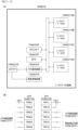
パチンコ遊技機1には、例えば図3に示すような主基板11、演出制御基板12、音声制御基板13、ランプ制御基板14、中継基板15などが搭載されている。その他にも、パチンコ遊技機1の背面には、例えば払出制御基板、情報端子基板、発射制御基板などといった、各種の基板が配置されている。さらには、電源基板17も搭載されている。各種制御基板は、導体パターンが形成されて電気部品を実装可能なプリント配線板などの電子回路基板だけでなく、電子回路基板に電気部品が実装されて特定の電気的機能を実現するように構成された電子回路実装基板を含む概念である。
(Substrate configuration)
The
パチンコ遊技機1では、商用電源などの外部電源におけるAC100Vといった交流電源からの電力を、電源基板17により主基板11や演出制御基板12などの各種制御基板を含めた電気部品に供給可能である。電源基板17は、例えば交流(AC)を直流(DC)に変換するための整流回路、所定の直流電圧を特定の直流電圧(例えば直流12Vや直流5Vなど)に変換するための電源回路などを備えている。
In the
主基板11は、メイン側の制御基板であり、パチンコ遊技機1における上記遊技の進行(特図ゲームの実行(保留の管理を含む)、普図ゲームの実行(保留の管理を含む)、大当り遊技状態、小当り遊技状態、遊技状態など)を制御する機能を有する。主基板11は、遊技制御用マイクロコンピュータ100、スイッチ回路110、ソレノイド回路111などを有する。
The
主基板11に搭載された遊技制御用マイクロコンピュータ100は、例えば1チップのマイクロコンピュータであり、ROM(Read Only Memory)101と、RAM(Random Access Memory)102と、CPU(Central Processing Unit)103と、乱数回路104と、I/O(Input/Output port)105とを備える。
The
CPU103は、ROM101に記憶されたプログラムを実行することにより、遊技の進行を制御する処理(主基板11の機能を実現する処理)を行う。このとき、ROM101が記憶する各種データ(後述の変動パターン、後述の演出制御コマンド、後述の各種決定を行う際に参照される各種テーブルなどのデータ)が用いられ、RAM102がメインメモリとして使用される。RAM102は、その一部または全部がパチンコ遊技機1に対する電力供給が停止しても、所定期間記憶内容が保存されるバックアップRAMとなっている。なお、ROM101に記憶されたプログラムの全部または一部をRAM102に展開して、RAM102上で実行するようにしてもよい。
The
乱数回路104は、遊技の進行を制御するときに使用される各種の乱数値(遊技用乱数)を示す数値データを更新可能にカウントする。遊技用乱数は、CPU103が所定のコンピュータプログラムを実行することで更新されるもの(ソフトウェアで更新されるもの)であってもよい。
The
I/O105は、例えば各種信号(後述の検出信号)が入力される入力ポートと、各種信号(第1特別図柄表示装置4A、第2特別図柄表示装置4B、普通図柄表示器20、第1保留表示器25A、第2保留表示器25B、普図保留表示器25Cなどを制御(駆動)する信号、ソレノイド駆動信号)を伝送するための出力ポートとを含んで構成される。
The I/
スイッチ回路110は、遊技球検出用の各種スイッチ(ゲートスイッチ21、始動口スイッチ(第1始動口スイッチ22Aおよび第2始動口スイッチ22B)、カウントスイッチ23)からの検出信号(遊技球が通過または進入してスイッチがオンになったことを示す検出信号など)を取り込んで遊技制御用マイクロコンピュータ100に伝送する。検出信号の伝送により、遊技球の通過または進入が検出されたことになる。
The
スイッチ回路110には、電源基板17からのリセット信号、電源断信号、クリア信号が取り込まれて遊技制御用マイクロコンピュータ100に伝送される。リセット信号は、遊技制御用マイクロコンピュータ100などの制御回路を動作停止状態とするための動作停止信号であり、電源監視回路、ウォッチドッグタイマ内蔵IC、システムリセットICのいずれかを用いて出力可能であればよい。電源断信号は、パチンコ遊技機1において用いられる所定電源電圧が所定値を超えるとオフ状態となり、所定電源電圧が所定値以下になった期間が電断基準時間以上まで継続したときにオン状態となる。クリア信号は、例えば電源基板17に設けられたクリアスイッチに対する押下操作などに応じてオン状態となる。
A reset signal, a power-off signal, and a clear signal from the power supply board 17 are taken into the
ソレノイド回路111は、遊技制御用マイクロコンピュータ100からのソレノイド駆動信号(例えば、ソレノイド81やソレノイド82をオンする信号など)を、普通電動役物用のソレノイド81や大入賞口扉用のソレノイド82に伝送する。
The
主基板11には、表示モニタ29、表示切替スイッチ30、設定キー51、設定切替スイッチ52、扉開放センサ90が接続されている。扉開放センサ90は、ガラス扉枠3aを含めた遊技機用枠3の開放を検知する。
A
主基板11(遊技制御用マイクロコンピュータ100)は、遊技の進行の制御の一部として、遊技の進行に応じて演出制御コマンド(遊技の進行状況等を指定(通知)するコマンド)を演出制御基板12に供給する。主基板11から出力された演出制御コマンドは、中継基板15により中継され、演出制御基板12に供給される。当該演出制御コマンドには、例えば主基板11における各種の決定結果(例えば、特図ゲームの表示結果(大当り種別を含む。)、特図ゲームを実行する際に使用される変動パターン(詳しくは後述))、遊技の状況(例えば、可変表示の開始や終了、大入賞口の開放状況、入賞の発生、保留記憶数、遊技状態)、エラーの発生等を指定するコマンド等が含まれる。
The main board 11 (game control microcomputer 100) is a production control board that sends production control commands (commands that specify (notify) the progress of the game, etc.) according to the progress of the game as part of the control of the progress of the game. Supply to 12. The production control command output from the
演出制御基板12は、主基板11とは独立したサブ側の制御基板であり、演出制御コマンドを受信し、受信した演出制御コマンドに基づいて演出(遊技の進行に応じた種々の演出であり、可動体32の駆動、エラー報知、電断復旧の報知等の各種報知を含む)を実行する機能を有する。
The
演出制御基板12には、演出制御用CPU120と、ROM121と、RAM122と、表示制御部123と、乱数回路124と、I/O125とが搭載されている。
The
演出制御用CPU120は、ROM121に記憶されたプログラムを実行することにより、表示制御部123とともに演出を実行するための処理(演出制御基板12の上記機能を実現するための処理であり、実行する演出の決定等を含む)を行う。このとき、ROM121が記憶する各種データ(各種テーブルなどのデータ)が用いられ、RAM122がメインメモリとして使用される。
The
演出制御用CPU120は、コントローラセンサユニット35Aやプッシュセンサ35Bからの検出信号(遊技者による操作を検出したときに出力される信号であり、操作内容を適宜示す信号)に基づいて演出の実行を表示制御部123に指示することもある。
The
表示制御部123は、VDP(Video Display Processor)、CGROM(Character Generator ROM)、VRAM(Video RAM)などを備え、演出制御用CPU120からの演出の実行指示に基づき、演出を実行する。
The
表示制御部123は、演出制御用CPU120からの演出の実行指示に基づき、実行する演出に応じた映像信号を画像表示装置5に供給することで、演出画像を画像表示装置5に表示させる。表示制御部123は、さらに、演出画像の表示に同期した音声出力や、遊技効果ランプ9の点灯/消灯を行うため、音指定信号(出力する音声を指定する信号)を音声制御基板13に供給したり、ランプ信号(ランプの点灯/消灯態様を指定する信号)をランプ制御基板14に供給したりする。また、表示制御部123は、可動体32を動作させる信号を当該可動体32または当該可動体32を駆動する駆動回路に供給する。
The
音声制御基板13は、スピーカ8L、8Rを駆動する各種回路を搭載しており、当該音指定信号に基づきスピーカ8L、8Rを駆動し、当該音指定信号が指定する音声をスピーカ8L、8Rから出力させる。
The
ランプ制御基板14は、遊技効果ランプ9を駆動する各種回路を搭載しており、当該ランプ信号に基づき遊技効果ランプ9を駆動し、当該ランプ信号が指定する態様で遊技効果ランプ9を点灯/消灯する。このようにして、表示制御部123は、音声出力、ランプの点灯/消灯を制御する。
The
なお、音声出力、ランプの点灯/消灯の制御(音指定信号やランプ信号の供給等)、可動体32の制御(可動体32を動作させる信号の供給等)は、演出制御用CPU120が実行するようにしてもよい。
Note that the
乱数回路124は、各種演出を実行するために使用される各種の乱数値(演出用乱数)を示す数値データを更新可能にカウントする。演出用乱数は、演出制御用CPU120が所定のコンピュータプログラムを実行することで更新されるもの(ソフトウェアで更新されるもの)であってもよい。
The
演出制御基板12に搭載されたI/O125は、例えば主基板11などから伝送された演出制御コマンドを取り込むための入力ポートと、各種信号(映像信号、音指定信号、ランプ信号)を伝送するための出力ポートとを含んで構成される。
The I/
演出制御基板12、音声制御基板13、ランプ制御基板14といった、主基板11以外の基板をサブ基板ともいう。パチンコ遊技機1のようにサブ基板が機能別に複数設けられていてもよいし、1のサブ基板が複数の機能を有するように構成してもよい。
Boards other than the
(動作)
次に、パチンコ遊技機1の動作(作用)を説明する。
(motion)
Next, the operation (function) of the
(主基板11の主要な動作)
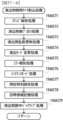
まず、主基板11における主要な動作を説明する。パチンコ遊技機1に対して電力供給が開始されると、遊技制御用マイクロコンピュータ100が起動し、CPU103によって遊技制御メイン処理が実行される。図4は、主基板11におけるCPU103が実行する遊技制御メイン処理を示すフローチャートである。
(Main operations of main board 11)
First, the main operations of the
図4に示す遊技制御メイン処理において、CPU103は、まず、割込禁止に設定する(ステップS1)。続いて、必要な初期設定を行う(ステップS2)。初期設定には、スタックポインタの設定、内蔵デバイス(CTC(カウンタ/タイマ回路)、パラレル入出力ポート等)のレジスタ設定、RAM102をアクセス可能状態にする設定等が含まれる。
In the game control main process shown in FIG. 4, the
次いで、復旧条件が成立したか否かを判定する(ステップS3)。復旧条件は、クリア信号がオフ状態であり、バックアップデータがあり、バックアップRAMが正常である場合に、成立可能である。パチンコ遊技機1の電力供給が開始されたときに、例えば電源基板17に設けられたクリアスイッチが押下操作されていれば、オン状態のクリア信号が遊技制御用マイクロコンピュータ100に入力される。このようなオン状態のクリア信号が入力されている場合には、ステップS3にて復旧条件が成立していないと判定すればよい。バックアップデータは、遊技制御用のバックアップRAMとなるRAM102に保存可能であればよい。ステップS3では、バックアップデータの有無やデータ誤りの有無などを確認あるいは検査して、復旧条件が成立し得るか否かを判定すればよい。
Next, it is determined whether the recovery conditions are satisfied (step S3). The recovery condition can be satisfied when the clear signal is off, there is backup data, and the backup RAM is normal. If, for example, a clear switch provided on the power supply board 17 is pressed when power supply to the
復旧条件が成立した場合には(ステップS3;Yes)、復旧処理(ステップS4)を実行した後に、設定確認処理(ステップS5)を実行する。ステップS4の復旧処理により、RAM102の記憶内容に基づいて作業領域の設定が行われる。RAM102に記憶されたバックアップデータを用いて作業領域を設定することで、電力供給が停止したときの遊技状態に復旧し、例えば特別図柄の変動中であった場合には、停止前の状態から特別図柄の変動を再開可能であればよい。
If the recovery condition is satisfied (step S3; Yes), the setting confirmation process (step S5) is executed after executing the recovery process (step S4). Through the recovery process in step S4, a work area is set based on the contents stored in the
復旧条件が成立しなかった場合には(ステップS3;No)、初期化処理(ステップS6)を実行した後に、設定変更処理(ステップS7)を実行する。ステップS6の初期化処理は、RAM102に記憶されるフラグ、カウンタ、バッファをクリアするクリア処理を含み、クリア処理の実行により作業領域に初期値が設定される。
If the recovery condition is not satisfied (step S3; No), initialization processing (step S6) is performed, and then setting change processing (step S7) is performed. The initialization process in step S6 includes a clear process for clearing the flags, counters, and buffers stored in the
ステップS5の設定確認処理では、予め定められた設定確認条件が成立したか否かを判定する。設定確認条件は、例えば電力供給が開始されたときに、扉開放センサ90からの検出信号がオン状態であるとともに設定キー51がオン操作されている場合に成立する。ステップS5の設定確認処理が実行されるのは、ステップS3において、クリア信号がオフ状態であることを含めた復旧条件が成立した場合である。したがって、設定確認条件が成立し得るのは、クリア信号がオフ状態である場合となるので、クリア信号がオフ状態であることも、設定確認条件に含めることができる。
In the setting confirmation process of step S5, it is determined whether predetermined setting confirmation conditions are satisfied. The setting confirmation condition is satisfied, for example, when the detection signal from the door
ステップS5の設定確認処理において設定確認条件が成立した場合には、パチンコ遊技機1において設定されている設定値を確認可能な設定確認状態となり、主基板11から演出制御基板12に対して、設定確認開始コマンドが送信される。設定確認状態においては、パチンコ遊技機1にて設定されている設定値を表示モニタ29の表示により確認することが可能となっている。設定確認状態を終了するときには、主基板11から演出制御基板12に対して、設定確認終了コマンドが送信される。
If the setting confirmation conditions are satisfied in the setting confirmation process in step S5, the setting confirmation state is reached in which the setting values set in the
パチンコ遊技機1が設定確認状態であるときには、パチンコ遊技機1における遊技の進行を停止させる遊技停止状態としてもよい。遊技停止状態であるときには、打球操作ハンドルの操作による遊技球の発射、各種スイッチによる遊技球の検出などが停止され、また、第1特別図柄表示器4Aや第2特別図柄表示器4B、普通図柄表示器20において、ハズレ図柄などを停止表示したり、ハズレ図柄とは異なる遊技停止状態に対応した表示が行われたりするように制御すればよい。設定確認状態が終了するときには、これに伴う遊技停止状態も終了すればよい。
When the
ステップS7の設定変更処理では、予め定められた設定変更条件が成立したか否かを判定する。設定変更条件は、例えば電力供給が開始されたときに、扉開放センサ90からの検出信号がオン状態であるとともに設定キー51がオン操作されている場合に成立する。設定変更条件は、クリア信号がオン状態であることを含んでいてもよい。
In the setting change process of step S7, it is determined whether predetermined setting change conditions are satisfied. The setting change condition is satisfied, for example, when the detection signal from the door
ステップS7の設定変更処理において設定変更条件が成立した場合には、パチンコ遊技機1において設定されている設定値を変更可能な設定変更状態となり、主基板11から演出制御基板12に対して、設定変更開始コマンドが送信される。設定変更状態においては、表示モニタ29に設定値が表示され、設定切替スイッチ52の操作を検出するごとに表示モニタ29に表示している数値を順次更新して表示する。その後、設定キー51が遊技場の係員などによる操作でオフとなったことに基づいて、表示モニタ29に表示されている設定値をRAM102のバックアップ領域に格納(更新記憶)するとともに、表示モニタ29を消灯させる。設定変更状態を終了するときには、主基板11から演出制御基板12に対して、設定変更終了コマンドが送信される。
If the setting change conditions are satisfied in the setting change process in step S7, the setting change state is entered in which the setting values set in the
パチンコ遊技機1が設定変更状態であるときには、設定確認状態であるときと同様に、パチンコ遊技機1を遊技停止状態としてもよい。設定変更状態が終了するときには、これに伴う遊技停止状態も終了すればよい。
When the
演出制御基板12側では、設定確認開始コマンドや設定変更開始コマンドを受信すると、設定確認中である旨や設定変更中である旨を報知する制御が行われてもよい。例えば、画像表示装置5において所定の画像を表示したり、スピーカ8L、8Rから所定の音を出力したり、遊技効果ランプ9といった発光部材を所定の態様により発光させたりしてもよい。
On the
クリア信号は、例えば電源基板17に設けられたクリアスイッチの押下操作などによりオン状態となる。したがって、電力供給が開始されたときに、扉開放センサ90からの検出信号がオンであるとともに設定キー51がオンである場合には、クリアスイッチがオンであればステップS6の初期化処理とともにステップS7の設定変更処理が実行されて設定変更状態に制御可能となり、クリアスイッチがオフであればステップS4の復旧処理とともにステップS5の設定確認処理が実行されて設定確認状態に制御可能となる。電力供給が開始されたときに、扉開放センサ90からの検出信号がオフである場合、または設定キー51がオフである場合には、クリアスイッチがオンであればステップS6の初期化処理が実行される一方で設定変更状態には制御されず、クリアスイッチがオフであればステップS4の復旧処理が実行される一方で設定確認状態には制御されない。
The clear signal is turned on, for example, by pressing down a clear switch provided on the power supply board 17. Therefore, when the power supply is started, if the detection signal from the door
設定確認処理または設定変更処理を実行した後に、CPU103は、乱数回路104を初期設定する乱数回路設定処理を実行する(ステップS8)。そして、所定時間(例えば2ms)毎に定期的にタイマ割込がかかるように遊技制御用マイクロコンピュータ100に内蔵されているCTCのレジスタの設定を行い(ステップS9)、割込みを許可する(ステップS10)。その後、ループ処理に入る。以後、所定時間(例えば2ms)ごとにCTCから割込み要求信号がCPU103へ送出され、CPU103は定期的にタイマ割込み処理を実行することができる。
After executing the setting confirmation process or the setting change process, the
こうした遊技制御メイン処理を実行したCPU103は、CTCからの割込み要求信号を受信して割込み要求を受け付けると、図5のフローチャートに示す遊技制御用タイマ割込み処理を実行する。図5に示す遊技制御用タイマ割込み処理を開始すると、CPU103は、まず、所定のスイッチ処理を実行することにより、スイッチ回路110を介してゲートスイッチ21、第1始動口スイッチ22A、第2始動口スイッチ22B、カウントスイッチ23といった各種スイッチからの検出信号の受信の有無を判定する(ステップS21)。続いて、所定のメイン側エラー処理を実行することにより、パチンコ遊技機1の異常診断を行い、その診断結果に応じて必要ならば警告を発生可能とする(ステップS22)。この後、所定の情報出力処理を実行することにより、例えばパチンコ遊技機1の外部に設置されたホール管理用コンピュータに供給される大当り情報(大当りの発生回数等を示す情報)、始動情報(始動入賞の回数等を示す情報)、確率変動情報(確変状態となった回数等を示す情報)などのデータを出力する(ステップS23)。
When the
情報出力処理に続いて、主基板11の側で用いられる遊技用乱数の少なくとも一部をソフトウェアにより更新するための遊技用乱数更新処理を実行する(ステップS24)。この後、CPU103は、特別図柄プロセス処理を実行する(ステップS25)。CPU103がタイマ割込み毎に特別図柄プロセス処理を実行することにより、特図ゲームの実行および保留の管理や、大当り遊技状態や小当り遊技状態の制御、遊技状態の制御などが実現される。
Following the information output process, a gaming random number updating process is executed to update at least a part of the gaming random numbers used on the
特別図柄プロセス処理に続いて、普通図柄プロセス処理が実行される(ステップS26)。CPU103がタイマ割込み毎に普通図柄プロセス処理を実行することにより、ゲートスイッチ21からの検出信号に基づく(通過ゲート41に遊技球が通過したことに基づく)普図ゲームの実行および保留の管理や、「普図当り」に基づく可変入賞球装置6Bの開放制御などを可能にする。普図ゲームの実行は、普通図柄表示器20を駆動することにより行われ、普図保留表示器25Cを点灯させることにより普図保留数を表示する。
Following the special symbol process, the normal symbol process is executed (step S26). The
普通図柄プロセス処理を実行した後、遊技制御用タイマ割込み処理の一部として、電断が発生したときの処理、賞球を払い出すための処理等などが行われてもよい。その後、CPU103は、コマンド制御処理を実行する(ステップS27)。CPU103は、上記各処理にて演出制御コマンドを送信設定することがある。ステップS27のコマンド制御処理では、送信設定された演出制御コマンドを演出制御基板12などのサブ側の制御基板に対して伝送させる処理が行われる。コマンド制御処理を実行した後には、割込みを許可してから、遊技制御用タイマ割込み処理を終了する。
After executing the normal symbol process processing, processing when a power outage occurs, processing for paying out prize balls, etc. may be performed as part of the game control timer interrupt processing. After that, the
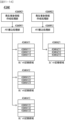
図6は、特別図柄プロセス処理として、図5に示すステップS25にて実行される処理の一例を示すフローチャートである。この特別図柄プロセス処理において、CPU103は、まず、始動入賞判定処理を実行する(ステップS101)。
FIG. 6 is a flowchart showing an example of the process executed in step S25 shown in FIG. 5 as the special symbol process process. In this special symbol process, the
始動入賞判定処理では、始動入賞の発生を検出し、RAM102の所定領域に保留情報を格納し保留記憶数を更新する処理が実行される。始動入賞が発生すると、表示結果(大当り種別を含む)や変動パターンを決定するための乱数値が抽出され、保留情報として記憶される。また、抽出した乱数値に基づいて、表示結果や変動パターンを先読判定する処理が実行されてもよい。保留情報や保留記憶数を記憶した後には、演出制御基板12に始動入賞の発生、保留記憶数、先読判定等の判定結果を指定するための演出制御コマンドを送信するための送信設定が行われる。こうして送信設定された始動入賞時の演出制御コマンドは、例えば特別図柄プロセス処理が終了した後、図4に示すステップS27のコマンド制御処理が実行されることなどにより、主基板11から演出制御基板12に対して伝送される。
In the starting winning determination process, a process is executed to detect the occurrence of a starting winning, store pending information in a predetermined area of the
ステップS101にて始動入賞判定処理を実行した後、CPU103は、RAM102に設けられた特図プロセスフラグの値に応じて、ステップS110~S120の処理のいずれかを選択して実行する。なお、特別図柄プロセス処理の各処理(ステップS110~S120)では、各処理に対応した演出制御コマンドを演出制御基板12に送信するための送信設定が行われる。
After executing the starting winning determination process in step S101, the
ステップS110の特別図柄通常処理は、特図プロセスフラグの値が“0”(初期値)のときに実行される。この特別図柄通常処理では、保留情報の有無などに基づいて、第1特図ゲームまたは第2特図ゲームを開始するか否かの判定が行われる。また、特別図柄通常処理では、表示結果決定用の乱数値に基づき、特別図柄や飾り図柄の表示結果を「大当り」または「小当り」とするか否かや「大当り」とする場合の大当り種別を、その表示結果が導出表示される以前に決定(事前決定)する。さらに、特別図柄通常処理では、決定された表示結果に対応して、特図ゲームにおいて停止表示させる確定特別図柄(大当り図柄や小当り図柄、ハズレ図柄のいずれか)が設定される。その後、特図プロセスフラグの値が“1”に更新され、特別図柄通常処理は終了する。なお、第2特図を用いた特図ゲームが第1特図を用いた特図ゲームよりも優先して実行されるようにしてもよい(特図2優先消化ともいう)。また、第1始動入賞口および第2始動入賞口への遊技球の入賞順序を記憶し、入賞順に特図ゲームの開始条件を成立させるようにしてもよい(入賞順消化ともいう)。
The special symbol normal process in step S110 is executed when the value of the special symbol process flag is "0" (initial value). In this special symbol normal processing, it is determined whether or not to start the first special symbol game or the second special symbol game based on the presence or absence of reservation information. In addition, in the special symbol normal processing, based on the random value for determining the display result, it is determined whether the display result of the special symbol or decorative symbol is a "big hit" or "small win" and the type of jackpot when it is determined to be a "jackpot". is determined (pre-determined) before the display result is derived and displayed. Furthermore, in the special symbol normal processing, a confirmed special symbol (any of a jackpot symbol, a small prize symbol, or a losing symbol) to be stopped and displayed in the special symbol game is set in accordance with the determined display result. After that, the value of the special symbol process flag is updated to "1", and the special symbol normal processing ends. Note that the special pattern game using the second special pattern may be executed with priority over the special pattern game using the first special pattern (also referred to as
乱数値に基づき各種の決定を行う場合には、ROM101に格納されている各種のテーブル(乱数値と比較される決定値が決定結果に割り当てられているテーブル)が参照される。主基板11における他の決定、演出制御基板12における各種の決定についても同じである。演出制御基板12においては、各種のテーブルがROM121に格納されている。
When making various decisions based on random numbers, various tables (tables in which decision values to be compared with random numbers are assigned to decision results) stored in the
ステップS111の変動パターン設定処理は、特図プロセスフラグの値が“1”のときに実行される。この変動パターン設定処理には、表示結果を「大当り」または「小当り」とするか否かの事前決定結果等に基づき、変動パターン決定用の乱数値を用いて変動パターンを複数種類のいずれかに決定する処理などが含まれている。変動パターン設定処理では、変動パターンを決定したときに、特図プロセスフラグの値が“2”に更新され、変動パターン設定処理は終了する。 The variation pattern setting process in step S111 is executed when the value of the special figure process flag is "1". In this fluctuation pattern setting process, based on the pre-determined result of whether the display result will be a "big hit" or "small hit", a random value for determining the fluctuation pattern is used to select one of multiple types of fluctuation patterns. It includes the process of determining the In the variation pattern setting process, when the variation pattern is determined, the value of the special figure process flag is updated to "2", and the variation pattern setting process ends.
変動パターンは、特図ゲームの実行時間(特図変動時間)(飾り図柄の可変表示の実行時間でもある)や、飾り図柄の可変表示の態様(リーチの有無等)、飾り図柄の可変表示中の演出内容(リーチ演出の種類等)を指定するものであり、可変表示パターンとも呼ばれる。 The variation pattern includes the execution time of the special figure game (special figure variation time) (also the execution time of the variable display of decorative symbols), the variable display mode of the ornamental symbols (the presence or absence of reach, etc.), and the variable display period of the decorative symbols. It specifies the content of the performance (type of reach performance, etc.), and is also called a variable display pattern.
ステップS112の特別図柄変動処理は、特図プロセスフラグの値が“2”のときに実行される。この特別図柄変動処理には、第1特別図柄表示装置4Aや第2特別図柄表示装置4Bにおいて特別図柄を変動させるための設定を行う処理や、その特別図柄が変動を開始してからの経過時間を計測する処理などが含まれている。また、計測された経過時間が変動パターンに対応する特図変動時間に達したか否かの判定も行われる。そして、特別図柄の変動を開始してからの経過時間が特図変動時間に達したときには、特図プロセスフラグの値が“3”に更新され、特別図柄変動処理は終了する。
The special symbol variation process in step S112 is executed when the value of the special symbol process flag is "2". This special symbol variation process includes a process of making settings for varying the special symbol in the first special
ステップS113の特別図柄停止処理は、特図プロセスフラグの値が“3”のときに実行される。この特別図柄停止処理には、第1特別図柄表示装置4Aや第2特別図柄表示装置4Bにて特別図柄の変動を停止させ、特別図柄の表示結果となる確定特別図柄を停止表示(導出)させるための設定を行う処理が含まれている。そして、表示結果が「大当り」である場合には特図プロセスフラグの値が“4”に更新される。その一方で、大当りフラグがオフであり、表示結果が「小当り」である場合には、特図プロセスフラグの値が“8”に更新される。また、表示結果が「ハズレ」である場合には、特図プロセスフラグの値が“0”に更新される。表示結果が「小当り」または「ハズレ」である場合、時短状態や確変状態に制御されているときであって、回数切りの終了成立する場合には、遊技状態も更新される。特図プロセスフラグの値が更新されると、特別図柄停止処理は終了する。
The special symbol stop process in step S113 is executed when the value of the special symbol process flag is "3". In this special symbol stopping process, the fluctuation of the special symbol is stopped in the first special
ステップS114の大当り開放前処理は、特図プロセスフラグの値が“4”のときに実行される。この大当り開放前処理には、表示結果が「大当り」となったことなどに基づき、大当り遊技状態においてラウンドの実行を開始して大入賞口を開放状態とするための設定を行う処理などが含まれている。大入賞口を開放状態とするときには、大入賞口扉用のソレノイド82に対してソレノイド駆動信号を供給する処理が実行される。このときには、例えば大当り種別がいずれであるかに対応して、大入賞口を開放状態とする開放上限期間や、ラウンドの上限実行回数を設定する。これらの設定が終了すると、特図プロセスフラグの値が“5”に更新され、大当り開放前処理は終了する。 The jackpot opening preprocessing in step S114 is executed when the value of the special figure process flag is "4". This jackpot opening pre-processing includes processing to start a round in the jackpot game state and set the jackpot opening state based on the display result being a "jackpot", etc. It is. When the big winning opening is opened, a process is executed to supply a solenoid drive signal to the solenoid 82 for the big winning opening door. At this time, for example, depending on the jackpot type, the opening upper limit period for keeping the jackpot open and the upper limit number of rounds to be executed are set. When these settings are completed, the value of the special figure process flag is updated to "5", and the jackpot release preprocessing is completed.
ステップS115の大当り開放中処理は、特図プロセスフラグの値が“5”のときに実行される。この大当り開放中処理には、大入賞口を開放状態としてからの経過時間を計測する処理や、その計測した経過時間やカウントスイッチ23によって検出された遊技球の個数などに基づいて、大入賞口を開放状態から閉鎖状態に戻すタイミングとなったか否かを判定する処理などが含まれている。そして、大入賞口を閉鎖状態に戻すときには、大入賞口扉用のソレノイド82に対するソレノイド駆動信号の供給を停止させる処理などを実行した後、特図プロセスフラグの値が“6”に更新し、大当り開放中処理を終了する。
The jackpot opening process in step S115 is executed when the value of the special figure process flag is "5". This jackpot opening process includes a process of measuring the elapsed time since the jackpot opening is opened, and a process of measuring the elapsed time from when the jackpot opening is opened, and based on the measured elapsed time and the number of game balls detected by the
ステップS116の大当り開放後処理は、特図プロセスフラグの値が“6”のときに実行される。この大当り開放後処理には、大入賞口を開放状態とするラウンドの実行回数が設定された上限実行回数に達したか否かを判定する処理や、上限実行回数に達した場合に大当り遊技状態を終了させるための設定を行う処理などが含まれている。そして、ラウンドの実行回数が上限実行回数に達していないときには、特図プロセスフラグの値が“5”に更新される一方、ラウンドの実行回数が上限実行回数に達したときには、特図プロセスフラグの値が“7”に更新される。特図プロセスフラグの値が更新されると、大当り解放後処理は終了する。 The jackpot opening process in step S116 is executed when the value of the special figure process flag is "6". This jackpot opening process includes a process to determine whether the number of rounds to open the jackpot has reached the set upper limit number of runs, and a process to enter the jackpot game state when the upper limit number of runs has been reached. This includes processing to make settings for terminating the process. When the number of executions of the round has not reached the upper limit number of executions, the value of the special figure process flag is updated to "5", while when the number of executions of the round has reached the upper limit number of executions, the value of the special figure process flag is updated to "5". The value is updated to "7". When the value of the special figure process flag is updated, the jackpot release post-processing ends.
ステップS117の大当り終了処理は、特図プロセスフラグの値が“7”のときに実行される。この大当り終了処理には、大当り遊技状態の終了を報知する演出動作としてのエンディング演出が実行される期間に対応した待ち時間が経過するまで待機する処理や、大当り遊技状態の終了に対応して確変制御や時短制御を開始するための各種の設定を行う処理などが含まれている。こうした設定が行われたときには、特図プロセスフラグの値が“0”に更新され、大当り終了処理は終了する。 The jackpot end process in step S117 is executed when the value of the special figure process flag is "7". This jackpot ending process includes a process of waiting until the waiting time corresponding to the period in which the ending performance is executed as a performance operation to notify the end of the jackpot gaming state, and a process of waiting until the waiting time corresponding to the end of the jackpot gaming state has changed. It includes processing to perform various settings for starting control and time-saving control. When such settings are made, the value of the special figure process flag is updated to "0", and the jackpot ending process ends.
ステップS118の小当り開放前処理は、特図プロセスフラグの値が“8”のときに実行される。この小当り開放前処理には、表示結果が「小当り」となったことに基づき、小当り遊技状態において大入賞口を開放状態とするための設定を行う処理などが含まれている。このときには、特図プロセスフラグの値が“9”に更新され、小当り開放前処理は終了する。 The small hit opening preprocessing in step S118 is executed when the value of the special figure process flag is "8". This small win opening pre-processing includes processing for setting the large winning opening to be open in the small winning gaming state based on the display result being "small winning". At this time, the value of the special figure process flag is updated to "9", and the small hit release preprocessing ends.
ステップS119の小当り開放中処理は、特図プロセスフラグの値が“9”のときに実行される。この小当り開放中処理には、大入賞口を開放状態としてからの経過時間を計測する処理や、その計測した経過時間などに基づいて、大入賞口を開放状態から閉鎖状態に戻すタイミングとなったか否かを判定する処理などが含まれている。大入賞口を閉鎖状態に戻して小当り遊技状態の終了タイミングとなったときには、特図プロセスフラグの値が“10”に更新され、小当り開放中処理は終了する。 The small hit opening process in step S119 is executed when the value of the special figure process flag is "9". This small win opening process includes a process that measures the elapsed time since the big winning opening was opened, and a timing to return the big winning opening from the open state to the closed state based on the measured elapsed time. This includes processing to determine whether or not the When the big prize opening is returned to the closed state and the end timing of the small winning game state comes, the value of the special figure process flag is updated to "10", and the small winning opening process ends.
ステップS120の小当り終了処理は、特図プロセスフラグの値が“10”のときに実行される。この小当り終了処理には、小当り遊技状態の終了を報知する演出動作が実行される期間に対応した待ち時間が経過するまで待機する処理などが含まれている。ここで、小当り遊技状態が終了するときには、小当り遊技状態となる以前のパチンコ遊技機1における遊技状態を継続させる。小当り遊技状態の終了時における待ち時間が経過したときには、特図プロセスフラグの値が“0”に更新され、小当り終了処理は終了する。
The small hit end process of step S120 is executed when the value of the special figure process flag is "10". This small win ending process includes a process of waiting until a waiting time corresponding to a period in which a performance operation to notify the end of the small win game state has elapsed. Here, when the small winning gaming state ends, the gaming state in the
パチンコ遊技機1は、設定値に応じて大当りの当選確率や出玉率が変わる構成とされている。例えば、特別図柄プロセス処理の特別図柄通常処理において、設定値に応じた表示結果判定テーブル(当選確率)を用いることにより、大当りの当選確率や出玉率が変わるようになっている。例えば設定値は1~6の6段階からなり、6が最も大当りの当選確率が高く、6、5、4、3、2、1の順に値が小さくなるほど大当りの当選確率が低くなる。この例において、設定値として6が設定されている場合には遊技者にとって最も有利度が高く、6、5、4、3、2、1の順に値が小さくなるほど有利度が段階的に低くなる。設定値に応じて大当りの当選確率が変われば、出玉率も設定値に応じて変わってもよい。大当りの当選確率は設定値にかかわらず一定であるのに対し、大当り遊技状態におけるラウンド数が設定値に応じて変わってもよい。パチンコ遊技機1は、遊技者にとっての有利度が異なる複数の設定値のうちいずれかを設定可能に構成されていればよい。パチンコ遊技機1において設定されている設定値は、主基板11の側から演出制御基板12の側へ設定値指定コマンドが送信されることにより通知される。
The
図7は、表示結果判定テーブルの構成例を示している。図7(A)は、変動特図が第1特図である場合に用いられる第1特図用表示結果判定テーブルの構成例を示し、図7(B)は、変動特図が第2特図である場合に用いられる第2特図用表示結果判定テーブルの構成例を示している。表示結果判定テーブルは、ROM101に記憶されているデータの集まりである。表示結果判定テーブルでは、設定値に応じて、乱数値MR1と比較される当り判定値が特別図柄の可変表示結果である特図表示結果に割り当てられている。乱数値MR1は、表示結果決定用の乱数値であり、0~65535の範囲でランダムに値が更新される。表示結果判定テーブルとして、第1特図と第2特図とで共通の表示結果判定テーブルを用いるようにしてもよい。
FIG. 7 shows an example of the configuration of the display result determination table. FIG. 7(A) shows a configuration example of the display result determination table for the first special symbol used when the variable special symbol is the first special symbol, and FIG. 7(B) shows a configuration example of the display result determination table for the first special symbol used when the variable special symbol is the second A configuration example of a second special figure display result determination table used in the case of a figure is shown. The display result determination table is a collection of data stored in the
表示結果判定テーブルにおいては、遊技状態が確変状態(高確状態)であるときに、通常状態または時短状態(低確状態)であるときよりも多くの判定値が、「大当り」の特図表示結果に割り当てられている。これにより、パチンコ遊技機1において確変制御が行われる確変状態といった高確状態であるときには、通常状態または時短状態といった低確状態であるときに比べて、大当り遊技状態に制御すると決定される確率が高くなる。
In the display result judgment table, when the gaming state is in a variable probability state (high probability state), more judgment values are displayed as special symbols for "jackpot" than when the gaming state is in the normal state or time saving state (low probability state). assigned to the result. As a result, when the
第1特図用表示結果判定テーブルにおいては、遊技状態や設定値にかかわらず、特図表示結果を「小当り」として小当り遊技状態に制御すると決定される確率が同一値となるように判定値が割り当てられている。第2特図用表示結果判定テーブルにおいては、遊技状態や設定値にかかわらず、特図表示結果を「小当り」として小当り遊技状態に制御すると決定される確率が第1特図用表示結果判定テーブルとは異なる同一値となるように判定値が割り当てられている。なお、設定値に応じて特図表示結果を「小当り」として小当り遊技状態に制御すると決定される確率を異ならせてもよい。変動特図にかかわらず特図表示結果を「小当り」として小当り遊技状態に制御すると決定される確率を同一確率としてもよい。 In the first special figure display result determination table, the probability that the special figure display result will be determined as a "small hit" and controlled to a small win gaming state is determined to be the same value, regardless of the gaming state or setting value. A value has been assigned. In the second special figure display result determination table, the first special figure display result is the probability that the special figure display result will be determined as a "small hit" and will be controlled in a small win game state, regardless of the gaming state or setting value. Judgment values are assigned so that they are the same value but different from those in the judgment table. In addition, the probability that the special figure display result is determined to be a "small win" and controlled to a small win gaming state may be varied depending on the set value. Regardless of the variable special figure, the probability of determining that the special figure display result will be a "small win" and control to a small win game state may be set to be the same probability.
第1特図用表示結果判定テーブルおよび第2特図用表示結果判定テーブルでは、遊技状態が通常状態または時短状態の場合に、当り判定値のうち1020から1237までの範囲が、設定値にかかわらず大当りを判定するための大当り判定値の共通数値範囲に設定されている。設定値が1の場合は、1020から1237までが「大当り」に割り当てられ、大当りを判定するための大当り判定値の共通数値範囲のみが設定されている一方で、設定値2~設定値6の場合は、大当り判定値の共通数値範囲から連続するように、1238から各設定値に応じた数値範囲が大当り判定値の非共通数値範囲に設定されている。
In the display result determination table for the first special figure and the display result determination table for the second special figure, when the gaming state is the normal state or the time saving state, the range from 1020 to 1237 of the hit judgment values is determined regardless of the set value. It is set to a common numerical range of jackpot determination values for determining jackpots. When the setting value is 1, 1020 to 1237 are assigned to "jackpot", and only the common numerical range of jackpot judgment values for determining jackpots is set, while setting
第1特図用表示結果判定テーブルおよび第2特図用表示結果判定テーブルでは、遊技状態が確変状態の場合に、当り判定値のうち1020から1346までの範囲が、設定値にかかわらず大当りを判定するための大当り判定値の共通数値範囲に設定されている。設定値が1の場合は、1020から1346までが「大当り」に割り当てられることで、大当りを判定するための大当り判定値の共通数値範囲のみが設定され、その一方で、設定値2~設定値6の場合は、大当り判定値の共通数値範囲から連続するように、1346から各設定値に応じた数値範囲が大当り判定値の非共通数値範囲に設定される。
In the display result determination table for the first special figure and the display result determination table for the second special figure, when the gaming state is in a variable probability state, the range from 1020 to 1346 among the hit determination values indicates that the jackpot will be won regardless of the set value. It is set to a common numerical range of jackpot judgment values for judgment. When the setting value is 1, by assigning 1020 to 1346 to "jackpot", only the common numerical range of jackpot judgment values for determining jackpots is set, and on the other hand, setting
第1特図用表示結果判定テーブルでは、遊技状態が通常状態または時短状態である場合に、当り判定値のうち32767から33094までの範囲が、設定値にかかわらず小当りを判定するための小当り判定値の共通数値範囲に設定されている。小当り判定値は、設定値が1~6のいずれである場合にも、大当り判定値の共通数値範囲および非共通数値範囲とは異なる数値範囲に設定されている。これにより、小当り判定値の数値範囲が各設定値に応じて変化する大当り判定値の範囲に重複することが防止されている。 In the display result determination table for the first special figure, when the gaming state is the normal state or the time saving state, the range from 32767 to 33094 of the hit determination values is the small value for determining a small hit regardless of the setting value. It is set to a common numerical range of hit judgment values. The small hit determination value is set to a numerical range different from the common numerical range and non-common numerical range of the jackpot determination value, regardless of the set value from 1 to 6. This prevents the numerical range of the small hit determination value from overlapping the range of the jackpot determination value, which changes according to each set value.
第1特図用表示結果判定テーブルでは、遊技状態が確変状態である場合に、遊技状態が通常状態または時短状態である場合と同じく、当り判定値のうち32767から33094までの範囲が、設定値にかかわらず小当りを判定するための小当り判定値の共通数値範囲に設定されている。小当り判定値は、設定値が1~6のいずれである場合にも、大当り判定値の共通数値範囲および非共通数値範囲とは異なる数値範囲に設定されている。これにより、小当り判定値の数値範囲が各設定値に応じて変化する大当り判定値の範囲に重複することが防止されている。 In the display result determination table for the first special figure, when the gaming state is in the variable probability state, the range from 32767 to 33094 of the hit judgment values is set to It is set to a common numerical range of the small hit determination value for determining a small hit regardless of the number of small hits. The small hit determination value is set to a numerical range different from the common numerical range and non-common numerical range of the jackpot determination value, regardless of the set value from 1 to 6. This prevents the numerical range of the small hit determination value from overlapping the range of the jackpot determination value, which changes according to each set value.
第2特図用表示結果判定テーブルでは、遊技状態が通常状態または時短状態である場合に、当り判定値のうち32767から33421までの範囲が、設定値にかかわらず小当りを判定するための小当り判定値の共通数値範囲に設定されている。小当り判定値は、設定値が1~6のいずれである場合にも、大当り判定値の共通数値範囲および非共通数値範囲とは異なる数値範囲に設定されている。これにより、小当り判定値の数値範囲が各設定値に応じて変化する大当り判定値の範囲に重複することが防止されている。 In the display result determination table for the second special figure, when the gaming state is the normal state or the time saving state, the range from 32767 to 33421 of the hit determination values is the small value for determining a small hit regardless of the set value. It is set to a common numerical range of hit judgment values. The small hit determination value is set to a numerical range different from the common numerical range and non-common numerical range of the jackpot determination value, regardless of the set value from 1 to 6. This prevents the numerical range of the small hit determination value from overlapping the range of the jackpot determination value, which changes according to each set value.
第2特図用表示結果判定テーブルでは、遊技状態が確変状態である場合に、遊技状態が通常状態または時短状態である場合と同じく、当り判定値のうち32767から33421までの範囲が、設定値にかかわらず小当りを判定するための小当り判定値の共通数値範囲に設定されている。小当り判定値は、設定値が1~6のいずれである場合にも、大当り判定値の共通数値範囲および非共通数値範囲とは異なる数値範囲に設定されている。これにより、小当り判定値の数値範囲が各設定値に応じて変化する大当り判定値の範囲に重複することが防止されている。 In the display result determination table for the second special figure, when the gaming state is in the variable probability state, the range from 32767 to 33421 of the hit judgment values is the set value, just as when the gaming state is in the normal state or time saving state. It is set to a common numerical range of the small hit determination value for determining a small hit regardless of the number of small hits. The small hit determination value is set to a numerical range different from the common numerical range and non-common numerical range of the jackpot determination value, regardless of the set value from 1 to 6. This prevents the numerical range of the small hit determination value from overlapping the range of the jackpot determination value, which changes according to each set value.
パチンコ遊技機1に設定可能な設定値は、5個以下や7個以上であってもよい。パチンコ遊技機1に設定される設定値が小さいほど遊技者にとって有利となるようにしてもよい。パチンコ遊技機1に設定される設定値に応じて遊技性が変化するようにしてもよい。例えば、パチンコ遊技機1に設定される設定値が1である場合は、通常状態での大当り確率が1/320、確変状態が65%の割合でループする遊技性(いわゆる確変ループタイプ)とし、パチンコ遊技機1に設定されている設定値が2である場合は、通常状態での大当り確率が1/200、大当り遊技中に遊技球が、特別可変入賞球装置7の内部に設けられた所定スイッチを通過することに基づいて大当り遊技終了後の遊技状態を確変状態に制御する一方で、変動特図に応じて大当り遊技中に遊技球が所定スイッチを通過する割合が異なる遊技性(いわゆるV確変タイプ)とし、パチンコ遊技機1に設定されている設定値が3である場合は、大当り確率が1/320で小当り確率が1/50であり、高ベース中(時短制御中)に遊技球が特別可変入賞球装置7の内部に設けられた所定スイッチを通過することに基づいて大当り遊技状態に制御する遊技性(いわゆる1種2種混合タイプ)としてもよい。パチンコ遊技機1に設定されている設定値が1~3のいずれかである場合は遊技性が同一であるが、これら設定値が1~3のいずれかである場合よりも大当り確率や小当り確率が高い一方で大当り遊技中に獲得可能な賞球数が少ない設定(例えば、パチンコ遊技機1に設定されている設定値が4~6のいずれかである場合)を設けてもよい。設定値に応じて遊技性を変化させる場合は、共通のスイッチを異なる用途に使用してもよい。具体的には、設定値が1~3の場合は、特別可変入賞球装置7内に設けられた所定スイッチを演出用スイッチ(遊技球が所定領域を通過する毎に所定の演出を実行するためのスイッチ)として使用し、設定値が4~6の場合は、所定スイッチを遊技用スイッチ(遊技球が所定スイッチを通過したことに基づいて遊技状態を確変状態や大当り遊技状態に制御するためのスイッチ)として使用してもよい。
The number of setting values that can be set in the
大当り種別は、大当り種別判定テーブルにおける判定値の割当てに基づいて、設定値に応じて異なる割合で決定されてもよい。あるいは、大当り種別は、設定値にかかわらず共通の割合で決定されてもよい。変動パターンは、変動パターン判定テーブルにおける判定値の割当てに基づいて、設定値に応じて異なる割合で決定されてもよい。あるいは、変動パターンは、設定値にかかわらず共通の割合で決定されてもよい。設定値に応じてノーマルリーチやスーパーリーチの実行割合が異なることで、ノーマルリーチやスーパーリーチが実行される頻度により設定値が示唆されてもよい。あるいは、設定値にかかわらずノーマルリーチやスーパーリーチの実行割合は共通であってもよい。その他、設定値に応じて、異なる割合で任意の設定示唆演出を実行可能としたものであってもよい。 The jackpot type may be determined at different ratios depending on the setting value based on the allocation of judgment values in the jackpot type judgment table. Alternatively, the jackpot type may be determined by a common ratio regardless of the setting value. The variation pattern may be determined at different rates depending on the set value, based on the allocation of determination values in the variation pattern determination table. Alternatively, the variation pattern may be determined at a common rate regardless of the set value. The setting value may be suggested by the frequency with which normal reach and super reach are performed by varying the execution rate of normal reach and super reach depending on the setting value. Alternatively, the execution rate of normal reach and super reach may be the same regardless of the setting value. In addition, it may be possible to perform arbitrary setting suggestion effects at different rates depending on the setting value.
(演出制御基板12の主要な動作)
次に、演出制御基板12における主要な動作を説明する。演出制御基板12では、電源基板等から電源電圧の供給を受けると、演出制御用CPU120が起動して、図8のフローチャートに示すような演出制御メイン処理を実行する。図8に示す演出制御メイン処理を開始すると、演出制御用CPU120は、まず、所定の初期化処理を実行して(ステップS71)、RAM122のクリアや各種初期値の設定、また演出制御基板12に搭載されたCTC(カウンタ/タイマ回路)のレジスタ設定等を行う。また、初期動作制御処理を実行する(ステップS72)。初期動作制御処理では、可動体32を駆動して初期位置に戻す制御、所定の動作確認を行う制御といった可動体32の初期動作を行う制御が実行される。
(Main operations of the production control board 12)
Next, the main operations in the
その後、タイマ割込みフラグがオンとなっているか否かの判定を行う(ステップS73)。タイマ割込みフラグは、例えばCTCのレジスタ設定に基づき、所定時間(例えば2ミリ秒)が経過するごとにオン状態にセットされる。このとき、タイマ割込みフラグがオフであれば(ステップS73;No)、ステップS73の処理を繰り返し実行して待機する。 Thereafter, it is determined whether the timer interrupt flag is on (step S73). The timer interrupt flag is set to an on state every time a predetermined time (for example, 2 milliseconds) elapses, based on the register setting of the CTC, for example. At this time, if the timer interrupt flag is off (step S73; No), the process of step S73 is repeatedly executed and the process waits.
また、演出制御基板12の側では、所定時間が経過するごとに発生するタイマ割込みとは別に、主基板11からの演出制御コマンドを受信するための割込みが発生する。この割込みは、例えば主基板11からの演出制御INT信号がオン状態となることにより発生する割込みである。演出制御INT信号がオン状態となることによる割込みが発生すると、演出制御用CPU120は、自動的に割込み禁止に設定するが、自動的に割込み禁止状態にならないCPUを用いている場合には、割込み禁止命令(DI命令)を発行することが望ましい。演出制御用CPU120は、演出制御INT信号がオン状態となることによる割込みに対応して、例えば所定のコマンド受信割込み処理を実行する。このコマンド受信割込み処理では、I/O125に含まれる入力ポートのうちで、中継基板15を介して主基板11から送信された制御信号を受信する所定の入力ポートより、演出制御コマンドを取り込む。このとき取り込まれた演出制御コマンドは、例えばRAM122に設けられた演出制御コマンド受信用バッファに格納する。その後、演出制御用CPU120は、割込み許可に設定してから、コマンド受信割込み処理を終了する。
Furthermore, on the side of the
ステップS73にてタイマ割込みフラグがオンである場合には(ステップS73;Yes)、タイマ割込みフラグをクリアしてオフ状態にするとともに(ステップS74)、コマンド解析処理を実行する(ステップS75)。コマンド解析処理では、例えば主基板11の遊技制御用マイクロコンピュータ100から送信されて演出制御コマンド受信用バッファに格納されている各種の演出制御コマンドを読み出した後に、その読み出された演出制御コマンドに対応した設定や制御などが行われる。例えば、どの演出制御コマンドを受信したかや演出制御コマンドが特定する内容等を演出制御プロセス処理等で確認できるように、読み出された演出制御コマンドをRAM122の所定領域に格納したり、RAM122に設けられた受信フラグをオンしたりする。また、演出制御コマンドが遊技状態を特定する場合、遊技状態に応じた背景の表示を表示制御部123に指示してもよい。
If the timer interrupt flag is on in step S73 (step S73; Yes), the timer interrupt flag is cleared and turned off (step S74), and command analysis processing is executed (step S75). In the command analysis process, for example, after reading various production control commands transmitted from the
ステップS75にてコマンド解析処理を実行した後には、演出制御プロセス処理を実行する(ステップS76)。演出制御プロセス処理では、例えば画像表示装置5の表示領域における演出画像の表示動作、スピーカ8L、8Rからの音声出力動作、遊技効果ランプ9および装飾用LEDといった装飾発光体における点灯動作、可動体32の駆動動作といった、各種の演出装置を動作させる制御が行われる。また、各種の演出装置を用いた演出動作の制御内容について、主基板11から送信された演出制御コマンド等に応じた判定や決定、設定などが行われる。
After executing the command analysis process in step S75, the production control process process is executed (step S76). In the effect control process processing, for example, the display operation of the effect image in the display area of the
ステップS76の演出制御プロセス処理に続いて、演出用乱数更新処理が実行され(ステップS77)、演出制御基板12の側で用いられる演出用乱数の少なくとも一部がソフトウェアにより更新される。その後、ステップS73の処理に戻る。ステップS73の処理に戻る前に、他の処理が実行されてもよい。
Following the performance control process processing in step S76, a performance random number update process is executed (step S77), and at least a portion of the performance random numbers used on the
図9は、演出制御プロセス処理として、図8のステップS76にて実行される処理の一例を示すフローチャートである。図9に示す演出制御プロセス処理において、演出制御用CPU120は、まず、先読予告設定処理を実行する(ステップS161)。先読予告設定処理では、例えば、主基板11から送信された始動入賞時の演出制御コマンドに基づいて、先読予告演出を実行するための判定や決定、設定などが行われる。また、当該演出制御コマンドから特定される保留記憶数に基づき保留表示を表示するための処理が実行される。
FIG. 9 is a flowchart showing an example of the process executed in step S76 of FIG. 8 as the production control process process. In the performance control process shown in FIG. 9, the
ステップS161の処理を実行した後、演出制御用CPU120は、例えばRAM122に設けられた演出プロセスフラグの値に応じて、以下のようなステップS170~S177の処理のいずれかを選択して実行する。
After executing the process of step S161, the
ステップS170の可変表示開始待ち処理は、演出プロセスフラグの値が“0”(初期値)のときに実行される処理である。この可変表示開始待ち処理は、主基板11から可変表示の開始を指定するコマンドなどを受信したか否かに基づき、画像表示装置5における飾り図柄の可変表示を開始するか否かを判定する処理などを含んでいる。画像表示装置5における飾り図柄の可変表示を開始すると判定された場合、演出プロセスフラグの値を“1”に更新し、可変表示開始待ち処理を終了する。
The variable display start waiting process in step S170 is a process that is executed when the value of the production process flag is "0" (initial value). This variable display start waiting process is a process of determining whether or not to start variable display of decorative patterns on the
ステップS171の可変表示開始設定処理は、演出プロセスフラグの値が“1”のときに実行される処理である。この可変表示開始設定処理では、演出制御コマンドにより特定される表示結果や変動パターンに基づいて、飾り図柄の可変表示の表示結果(確定飾り図柄)、飾り図柄の可変表示の態様、リーチ演出や各種予告演出などの各種演出の実行の有無やその態様や実行開始タイミングなどを決定する。そして、その決定結果等を反映した演出制御パターン(表示制御部123に演出の実行を指示するための制御データの集まり)を設定する。その後、設定した演出制御パターンに基づいて、飾り図柄の可変表示の実行開始を表示制御部123に指示し、演出プロセスフラグの値を“2”に更新し、可変表示開始設定処理を終了する。表示制御部123は、飾り図柄の可変表示の実行開始の指示により、画像表示装置5において、飾り図柄の可変表示を開始させる。
The variable display start setting process in step S171 is a process that is executed when the value of the production process flag is "1". In this variable display start setting process, based on the display result and fluctuation pattern specified by the production control command, the display result of the variable display of the decorative pattern (determined decorative pattern), the mode of variable display of the decorative pattern, the reach effect, etc. It determines whether or not various performances such as preview performances are to be executed, their mode, execution start timing, and the like. Then, a performance control pattern (a collection of control data for instructing the
ステップS172の可変表示中演出処理は、演出プロセスフラグの値が“2”のときに実行される処理である。この可変表示中演出処理において、演出制御用CPU120は、表示制御部123を指示することで、ステップS171にて設定された演出制御パターンに基づく演出画像を画像表示装置5の表示画面に表示させることや、可動体32を駆動させること、音声制御基板13に対する指令(効果音信号)の出力によりスピーカ8L、8Rから音声や効果音を出力させること、ランプ制御基板14に対する指令(電飾信号)の出力により遊技効果ランプ9や装飾用LEDを点灯/消灯/点滅させることといった、飾り図柄の可変表示中における各種の演出制御を実行する。こうした演出制御を行った後、例えば演出制御パターンから飾り図柄の可変表示終了を示す終了コードが読み出されたこと、あるいは、主基板11から確定飾り図柄を停止表示させることを指定するコマンドを受信したことなどに対応して、飾り図柄の表示結果となる確定飾り図柄を停止表示させる。確定飾り図柄を停止表示したときには、演出プロセスフラグの値が“3”に更新され、可変表示中演出処理は終了する。
The variable display effect processing in step S172 is a process that is executed when the value of the effect process flag is "2". In this variable display performance process, the
ステップS173の特図当り待ち処理は、演出プロセスフラグの値が“3”のときに実行される処理である。この特図当り待ち処理において、演出制御用CPU120は、主基板11から大当り遊技状態または小当り遊技状態を開始することを指定する演出制御コマンドの受信があったか否かを判定する。そして、大当り遊技状態または小当り遊技状態を開始することを指定する演出制御コマンドを受信したきに、そのコマンドが大当り遊技状態の開始を指定するものであれば、演出プロセスフラグの値を“6”に更新する。これに対して、そのコマンドが小当り遊技状態の開始を指定するものであれば、演出プロセスフラグの値を小当り中演出処理に対応した値である“4”に更新する。また、大当り遊技状態または小当り遊技状態を開始することを指定するコマンドを受信せずに、当該コマンドの受信待ち時間が経過したときには、特図ゲームにおける表示結果が「ハズレ」であったと判定して、演出プロセスフラグの値を初期値である“0”に更新する。演出プロセスフラグの値を更新すると、特図当り待ち処理を終了する。
The special figure hit waiting process in step S173 is a process that is executed when the value of the production process flag is "3". In this special figure winning waiting process, the
ステップS174の小当り中演出処理は、演出プロセスフラグの値が“4”のときに実行される処理である。この小当り中演出処理において、演出制御用CPU120は、例えば小当り遊技状態における演出内容に対応した演出制御パターン等を設定し、その設定内容に基づく小当り遊技状態における各種の演出制御を実行する。また、小当り中演出処理では、例えば主基板11から小当り遊技状態を終了することを指定するコマンドを受信したことに対応して、演出プロセスフラグの値を小当り終了演出に対応した値である“5”に更新し、小当り中演出処理を終了する。
The small hit performance process in step S174 is a process that is executed when the value of the performance process flag is "4". In this small win performance processing, the
ステップS175の小当り終了演出処理は、演出プロセスフラグの値が“5”のときに実行される処理である。この小当り終了演出処理において、演出制御用CPU120は、例えば小当り遊技状態の終了などに対応した演出制御パターン等を設定し、その設定内容に基づく小当り遊技状態の終了時における各種の演出制御を実行する。その後、演出プロセスフラグの値を初期値である“0”に更新し、小当り終了演出処理を終了する。
The small hit end production process in step S175 is a process that is executed when the value of the production process flag is "5". In this small hit end performance process, the
ステップS176の大当り中演出処理は、演出プロセスフラグの値が“6”のときに実行される処理である。この大当り中演出処理において、演出制御用CPU120は、例えば大当り遊技状態における演出内容に対応した演出制御パターン等を設定し、その設定内容に基づく大当り遊技状態における各種の演出制御を実行する。また、大当り中演出処理では、例えば主基板11から大当り遊技状態を終了することを指定するコマンドを受信したことに対応して、演出プロセスフラグの値をエンディング演出処理に対応した値である“7”に更新し、大当り中演出処理を終了する。
The jackpot performance process in step S176 is a process that is executed when the value of the performance process flag is "6". In this jackpot performance process, the
ステップS177のエンディング演出処理は、演出プロセスフラグの値が“7”のときに実行される処理である。このエンディング演出処理において、演出制御用CPU120は、例えば大当り遊技状態の終了などに対応した演出制御パターン等を設定し、その設定内容に基づく大当り遊技状態の終了時におけるエンディング演出の各種の演出制御を実行する。その後、演出プロセスフラグの値を初期値である“0”に更新し、エンディング演出処理を終了する。
The ending effect processing in step S177 is a process that is executed when the value of the effect process flag is "7". In this ending performance processing, the
(基本説明の変形例)
この発明は、上記基本説明で説明したパチンコ遊技機1に限定されず、本発明の趣旨を逸脱しない範囲で、様々な変形および応用が可能である。
(Variation example of basic explanation)
This invention is not limited to the
上記基本説明のパチンコ遊技機1は、入賞の発生に基づいて所定数の遊技媒体を景品として払い出す払出式遊技機であったが、遊技媒体を封入し入賞の発生に基づいて得点を付与する封入式遊技機であってもよい。
The
特別図柄の可変表示中に表示されるものは1種類の図柄(例えば、「-」を示す記号)だけで、当該図柄の表示と消灯とを繰り返すことによって可変表示を行うようにしてもよい。さらに可変表示中に当該図柄が表示されるものも、可変表示の停止時には、当該図柄が表示されなくてもよい(表示結果としては「-」を示す記号が表示されなくてもよい)。 Only one type of symbol (for example, a symbol indicating "-") may be displayed during the variable display of the special symbol, and the variable display may be performed by repeatedly displaying and extinguishing the symbol. Further, even if the symbol is displayed during the variable display, the symbol does not need to be displayed when the variable display is stopped (the symbol indicating "-" does not need to be displayed as a display result).
上記基本説明では、遊技機としてパチンコ遊技機1を示したが、メダルが投入されて所定の賭け数が設定され、遊技者による操作レバーの操作に応じて複数種類の図柄を回転させ、遊技者によるストップボタンの操作に応じて図柄を停止させたときに停止図柄の組合せが特定の図柄の組み合わせになると、所定数のメダルが遊技者に払い出されるゲームを実行可能なスロット機(例えば、ビッグボーナス、レギュラーボーナス、RT、AT、ART、CZ(以下、ボーナス等)のうち1以上を搭載するスロット機)にも本発明を適用可能である。
In the above basic explanation, the
本発明を実現するためのプログラムおよびデータは、パチンコ遊技機1に含まれるコンピュータ装置などに対して、着脱自在の記録媒体により配布・提供される形態に限定されるものではなく、予めコンピュータ装置などの有する記憶装置にインストールしておくことで配布される形態を採っても構わない。さらに、本発明を実現するためのプログラムおよびデータは、通信処理部を設けておくことにより、通信回線等を介して接続されたネットワーク上の、他の機器からダウンロードすることによって配布する形態を採っても構わない。
The program and data for realizing the present invention are not limited to the form in which they are distributed and provided to a computer device included in the
そして、ゲームの実行形態も、着脱自在の記録媒体を装着することにより実行するものだけではなく、通信回線等を介してダウンロードしたプログラムおよびデータを、内部メモリ等に一旦格納することにより実行可能とする形態、通信回線等を介して接続されたネットワーク上における、他の機器側のハードウェア資源を用いて直接実行する形態としてもよい。さらには、他のコンピュータ装置等とネットワークを介してデータの交換を行うことによりゲームを実行するような形態とすることもできる。 The game can be executed not only by attaching a removable recording medium, but also by temporarily storing the program and data downloaded via a communication line in internal memory, etc. It may also be executed directly using hardware resources of other devices on a network connected via a communication line or the like. Furthermore, the game may be executed by exchanging data with other computer devices via a network.
なお、本明細書において、演出の実行割合などの各種割合の比較の表現(「高い」、「低い」、「異ならせる」などの表現)は、一方が「0%」の割合であることを含んでもよい。例えば、一方が「0%」の割合で、他方が「100%」の割合または「100%」未満の割合であることも含む。 In addition, in this specification, expressions that compare various proportions such as the execution rate of production (expressions such as "higher", "lower", "different", etc.) do not mean that one is a proportion of "0%". May include. For example, one of the ratios is "0%" and the other is "100%" or a ratio of less than "100%".
(設定示唆演出に関する特徴部の説明)
以下、パチンコ遊技機1における設定示唆演出に関する特徴部について説明する。この特徴部では、可変表示の実行中に、所定割合でパチンコ遊技機1における設定値を示唆する設定示唆演出を実行可能である。
(Explanation of features related to setting suggestion effects)
Hereinafter, the characteristic parts regarding the setting suggestion performance in the
図10-1は、可変表示開始設定処理として、演出制御プロセス処理のステップS171にて実行される処理の一例を示すフローチャートである。可変表示開始設定処理では、停止図柄決定処理が実行される(ステップS201)。停止図柄決定処理では、飾り図柄の可変表示における最終停止図柄といった、飾り図柄の可変表示において停止表示される飾り図柄の組合せが決定される。停止図柄決定処理に続いて、予告演出決定処理が実行される(ステップS202)。予告演出決定処理は、有利示唆演出に含まれる予告演出を決定可能とする。 FIG. 10-1 is a flowchart showing an example of the process executed in step S171 of the production control process process as the variable display start setting process. In the variable display start setting process, a stop symbol determination process is executed (step S201). In the stop symbol determination process, a combination of decorative symbols to be stopped and displayed in the variable display of decorative symbols, such as the final stop symbol in the variable display of decorative symbols, is determined. Following the stop symbol determination process, a preview performance determination process is executed (step S202). The preview performance determination process enables determining the preview performance included in the advantageous suggestion performance.
予告演出決定処理が実行された後には、演出制御パターンを予め用意された複数パターンのいずれかに決定する(ステップS203)。演出制御パターンは、特図変動時演出制御パターン、予告演出制御パターン、その他、各種の演出実行を制御するための制御パターンなどを含んでいればよい。例えば変動パターン指定コマンドで示された変動パターンなどに対応して、複数用意された特図変動時演出制御パターンのいずれかを選択し、使用パターンとしてセットする。また、ステップS202の予告演出決定処理による決定結果に対応して、複数用意された予告演出制御パターンのいずれかを選択し、使用パターンとしてセットしてもよい。なお、特図変動時演出制御パターン、予告演出制御パターンとして、別個の演出制御パターンをセットするものに限定されず、各演出の実行設定の組合せに対応した1の演出制御パターンをセットするものであってもよい。 After the preview performance determination process is executed, the performance control pattern is determined to be one of a plurality of patterns prepared in advance (step S203). The performance control pattern may include a special symbol variation performance control pattern, a preview performance control pattern, and other control patterns for controlling various performance executions. For example, in response to a variation pattern indicated by a variation pattern designation command, one of a plurality of prepared special symbol variation performance control patterns is selected and set as the pattern to be used. Further, one of the plurality of prepared preview performance control patterns may be selected and set as the pattern to be used in accordance with the determination result of the preview performance determination process in step S202. In addition, the performance control pattern at the time of special figure change and the advance notice performance control pattern are not limited to those that set separate performance control patterns, but one performance control pattern that corresponds to the combination of execution settings of each performance. There may be.
ステップS203により演出制御パターンが決定されると、例えば変動パターン指定コマンドにより指定された変動パターンに対応して、RAM122の所定領域(演出制御タイマ設定部など)に設けられた演出制御プロセスタイマの初期値を設定する(ステップS204)。また、画像表示装置5の画面上にて飾り図柄などの変動を開始させるための設定を行う(ステップS205)。このときには、ステップS203にて決定された演出制御パターン(特図変動時演出制御パターン)に含まれる表示制御データが指定する表示制御指令を表示制御部123のVDPに対して伝送させることなどにより、画像表示装置5の画面上に設けられた「左」、「中」、「右」の各飾り図柄表示エリア5L、5C、5Rにて飾り図柄の変動を開始させればよい。
When the production control pattern is determined in step S203, for example, the initial stage of the production control process timer provided in a predetermined area of the RAM 122 (production control timer setting section, etc.) corresponds to the variation pattern specified by the variation pattern specification command. A value is set (step S204). Further, settings are made to start changing decorative patterns and the like on the screen of the image display device 5 (step S205). At this time, by transmitting a display control command specified by the display control data included in the production control pattern (special figure variation production control pattern) determined in step S203 to the VDP of the
続いて、可変表示開始時の保留表示更新設定を行う(ステップS206)。例えば、画像表示装置5の画面上に設けられた保留表示エリアにおいて、保留番号「1」に対応した表示部位(左端の表示部位)を消去(消化)するとともに、他の保留番号「2」~「4」などに対応した表示部位にある保留表示を1つずつ左方向に移動(シフト)させる。これにより、保留表示のシフトが行われる。画像表示装置5の画面上に設けられたアクティブ表示部では、保留表示エリアにおいて消去(消化)した保留表示に対応したアクティブ表示が行われるようにすればよい。なお、保留記憶数が「0」であるときに、第1始動入賞や第2始動入賞の発生に基づいて直ちに可変表示が開始される場合には、保留表示を更新することなく、アクティブ表示エリアにおけるアクティブ表示を更新するための設定が行われてもよい。その後、演出プロセスフラグの値を可変表示中演出処理に対応した値である“2”に更新してから(ステップS207)、可変表示開始設定処理を終了する。
Subsequently, the pending display update setting at the time of starting the variable display is performed (step S206). For example, in the hold display area provided on the screen of the
図10-2は、停止図柄決定処理として、可変表示開始設定処理のステップS201にて実行される処理の一例を示すフローチャートである。停止図柄決定処理では、スーパーリーチのリーチ演出が実行されるか否かを判定する(ステップS221)。スーパーリーチのリーチ演出が実行されるか否かは、例えば主基板11から伝送された変動パターン指定コマンドで示された変動パターンに基づいて判定可能である。
FIG. 10-2 is a flowchart showing an example of the process executed in step S201 of the variable display start setting process as the stop symbol determination process. In the stop symbol determination process, it is determined whether a super reach effect is to be executed (step S221). Whether or not the super reach effect is executed can be determined based on the variation pattern indicated by the variation pattern designation command transmitted from the
スーパーリーチのリーチ演出が実行されない場合には(ステップS221;No)、非リーチ時やノーマルリーチ時の最終停止図柄を決定して(ステップS222)、停止図柄決定処理を終了する。非リーチ時には、可変表示結果が「ハズレ」になる。ノーマルリーチ時には、可変表示結果が「大当り」になる場合と、可変表示結果が「ハズレ」になる場合とが含まれている。飾り図柄の可変表示の態様がリーチ態様とならない非リーチ時には、最終停止図柄として、非リーチ組合せの確定飾り図柄が停止表示される。非リーチ時の最終停止図柄は、「左」および「右」の飾り図柄表示エリア5L、5Rで異なる(不一致の)飾り図柄となるように決定される。可変表示結果が「ハズレ」になるノーマルリーチ時には、リーチハズレ時の最終停止図柄として、リーチハズレ組合せの確定飾り図柄が停止表示される。リーチハズレ時の最終停止図柄は、「左」および「右」の飾り図柄表示エリア5L、5Rで同一の(一致する)飾り図柄となるように決定される。可変表示結果が「大当り」になるノーマルリーチ時には、大当り時の最終停止図柄として、大当り組合せの確定飾り図柄が停止表示される。大当り時の最終停止図柄は、「左」、「中」、「右」の飾り図柄表示エリア5L、5C、5Rにて同一の(一致する)飾り図柄となるように決定される。
If the super reach effect is not executed (step S221; No), the final stop symbol at the time of non-reach or normal reach is determined (step S222), and the stop symbol determination process is ended. When there is no reach, the variable display result will be "losing". At the time of normal reach, there are cases where the variable display result is a "jackpot" and cases where the variable display result is a "loss". When the variable display mode of the decorative symbols is not a ready-to-reach mode, a fixed decorative symbol of a non-reachable combination is stopped and displayed as the final stop symbol. The final stop symbol at the time of non-reach is determined so that the "left" and "right" decorative
スーパーリーチのリーチ演出が実行される場合には(ステップS221;Yes)、スーパーリーチ時の最終停止図柄を決定する(ステップS223)。スーパーリーチ時には、可変表示結果が「大当り」になる場合と、可変表示結果が「ハズレ」になる場合とが含まれている。可変表示結果が「ハズレ」になるスーパーリーチ時には、リーチハズレ時の最終停止図柄として、リーチハズレ組合せの確定飾り図柄が停止表示される。可変表示結果が「大当り」になる大当り時には、大当り時の最終停止図柄として、大当り組合せの確定飾り図柄が停止表示される。 When the reach effect of super reach is executed (step S221; Yes), the final stop symbol at the time of super reach is determined (step S223). At the time of super reach, there are cases where the variable display result becomes a "jackpot" and cases where the variable display result becomes a "loss". At the time of super reach where the variable display result is "lose", the determined decorative symbol of the reach loss combination is stopped and displayed as the final stop symbol at the time of reach loss. At the time of a jackpot where the variable display result is a "jackpot", the final decorative symbol of the jackpot combination is stopped and displayed as the final stop symbol at the time of the jackpot.
スーパーリーチ時には、可変表示結果が「大当り」になるか「ハズレ」になるかにかかわらず、「左」および「右」の飾り図柄表示エリア5L、5Rで同一の(一致する)飾り図柄が、確定飾り図柄として停止表示される。このようなリーチハズレ組合せや大当り組合せを構成する左右の飾り図柄は、リーチ図柄ともいう。リーチ図柄として決定可能な飾り図柄は、例えば1~7の数字に対応する7種類の飾り図柄といった、複数種類の飾り図柄を含んでいればよい。数字に対応する飾り図柄は、数字を示す演出画像のみであってもよいし、数字に加えて各種のキャラクタを示す演出画像であってもよい。リーチ図柄は、リーチ図柄決定用の乱数値を示す数値データに基づいて、ROM121に予め記憶されて用意されたリーチ図柄決定テーブルを参照することなどにより、複数の飾り図柄のいずれかに決定されるようにすればよい。リーチ図柄決定用の乱数値を示す数値データは、RAM122に設けられたランダムカウンタや乱数回路124の一方または両方を用いて、更新可能であればよい。
At the time of super reach, regardless of whether the variable display result is a "jackpot" or a "loss", the same (matching) decorative pattern will be displayed in the "left" and "right" decorative
リーチ図柄決定テーブルでは、可変表示結果が「ハズレ」であるか「大当り」であるかに応じて、リーチ図柄となる飾り図柄に割り当てられた判定値の個数が異なっていてもよい。例えば、可変表示結果が「ハズレ」である場合には、1の数字に対応する飾り図柄の決定割合が最も高くなり、2の数字、3の数字、4の数字、5の数字、6の数字となるに従って、飾り図柄の決定割合が低くなり、7の数字に対応する飾り図柄の決定割合が最も低くなる。これに対し、可変表示結果が「大当り」である場合には、1の数字に対応する飾り図柄の決定割合が最も低くなり、2の数字、3の数字、4の数字、5の数字、6の数字となるに従って、飾り図柄の決定割合が高くなり、7の数字に対応する飾り図柄の決定割合が最も高くなる。このような決定割合の設定では、7の数字に対応する飾り図柄がリーチ図柄として停止表示された場合に、可変表示結果が「大当り」となり大当り遊技状態に制御される割合が最も高くなり、6の数字、5の数字、4の数字、3の数字、2の数字となるに伴い、リーチ図柄として停止表示された場合の可変表示結果が「大当り」となり大当り遊技状態に制御される割合が低くなり、1の数字に対応する飾り図柄がリーチ図柄として停止表示された場合の可変表示結果が「大当り」となり大当り遊技状態に制御される割合が最も低くなる。なお、リーチ図柄決定テーブルでは、可変表示結果が「ハズレ」であるか「大当り」であるかにかかわらず、リーチ図柄となる飾り図柄に割り当てられた判定値の個数が同じであってもよい。リーチ図柄となる飾り図柄ごとに割り当てられた判定値の個数が異なってもよいし、リーチ図柄となる飾り図柄にかかわらず割り当てられた判定値の個数が同じであってもよい。大当り種別に応じて、リーチ図柄となる飾り図柄の決定割合が異なってもよい。
In the ready-to-win symbol determination table, the number of determination values assigned to decorative symbols that are ready-to-win symbols may vary depending on whether the variable display result is a "loss" or a "jackpot." For example, when the variable display result is a "lose", the determination rate of the decorative pattern corresponding to the
ステップS223に続いて、決定されたリーチ図柄は7の数字に対応する飾り図柄であるか否かを判定する(ステップS224)。このとき、リーチ図柄が7以外の数字に対応する飾り図柄であれば(ステップS224;No)、停止図柄決定処理を終了する。リーチ図柄が7の数字に対応する飾り図柄である場合には(ステップS224;Yes)、設定示唆演出を実行するか否かに応じた設定示唆演出の有無を決定する(ステップS225)。設定示唆演出は、設定示唆演出実行決定用の乱数値を示す数値データに基づいて、ROM121に予め記憶されて用意された設定示唆演出実行決定テーブルを参照することなどにより、実行の有無が決定されるようにすればよい。設定示唆演出実行決定用の乱数値を示す数値データは、RAM122に設けられたランダムカウンタや乱数回路124の一方または両方を用いて、更新可能であればよい。設定示唆演出の有無として、設定示唆演出を実行しない「演出なし」、または、設定示唆演出を実行する「演出あり」のうちで、いずれかに決定される。
Following step S223, it is determined whether the determined ready-to-reach symbol is a decorative symbol corresponding to the number 7 (step S224). At this time, if the ready-to-reach symbol is a decorative symbol corresponding to a number other than 7 (step S224; No), the stop symbol determination process is ended. If the ready-to-reach symbol is a decorative symbol corresponding to the number 7 (step S224; Yes), the presence or absence of a setting suggestion performance is determined depending on whether or not the setting suggestion performance is to be executed (step S225). Whether or not to perform the setting suggestion effect is determined by referring to a setting suggestion effect execution determination table stored in advance in the
ステップS225の決定結果に基づいて、設定示唆演出を実行する「演出あり」に決定されたか否かを判定する(ステップS226)。設定示唆演出を実行しない「演出なし」に決定された場合には(ステップS226;No)、停止図柄決定処理を終了する。「演出あり」に決定された場合には(ステップS226;Yes)、パチンコ遊技機1に設定されている設定値を特定する(ステップS227)。演出制御用CPU120は、パチンコ遊技機1の電源投入時に、主基板11の側から送信された設定値通知コマンドを受信し、通知された設定値をRAM122の所定領域に格納すればよい。これにより、ステップS227では、RAM122に格納されている設定値を特定すればよい。
Based on the determination result in step S225, it is determined whether or not it has been determined that the setting suggestion effect is to be performed (with effect) (step S226). If it is determined that the setting suggestion performance is not executed (step S226; No), the stop symbol determination process is ended. If it is determined that "with effect" (step S226; Yes), the setting value set in the
ステップS227に続いて、設定示唆パターンを決定してから(ステップS228)、停止図柄決定処理を終了する。設定示唆パターンは、設定示唆パターン決定用の乱数値を示す数値データに基づいて、ROM121に予め記憶されて用意された設定示唆パターン決定テーブルを参照することなどにより、複数の設定示唆パターンのうちいずれかに決定されるようにすればよい。設定示唆パターン決定用の乱数値を示す数値データは、RAM122に設けられたランダムカウンタや乱数回路124の一方または両方を用いて、更新可能であればよい。
Following step S227, a setting suggestion pattern is determined (step S228), and then the stop symbol determination process is ended. The setting suggestion pattern is selected from among a plurality of setting suggestion patterns by referring to a setting suggestion pattern determination table stored in advance in the
図10-3は、設定示唆演出実行決定テーブルに関する設定例を示している。例えばROM121には、設定示唆演出実行決定テーブルとして、図10-3に示す決定テーブルTA01を構成するテーブルデータが予め記憶されている。停止図柄決定処理のステップS225では、決定テーブルTA01を参照することなどにより、設定示唆演出の有無が決定される。決定テーブルTA01では、可変表示結果が「ハズレ」であるか「大当り」であるかに応じて、設定示唆演出の有無に割り当てられた判定値の個数が異なっている。例えば、可変表示結果が「大当り」である場合には、可変表示結果が「ハズレ」である場合よりも、設定示唆演出を実行する「演出あり」の決定割合が高くなる。このような決定割合の設定では、設定示唆演出が実行された場合に、設定示唆演出が実行されない場合よりも、可変表示結果が「大当り」となり大当り遊技状態に制御される割合が高くなる。なお、設定示唆演出実行決定テーブルでは、可変表示結果が「ハズレ」であるか「大当り」であるかにかかわらず、設定示唆演出の有無に割り当てられた判定値の個数が同じであってもよい。
FIG. 10-3 shows a setting example regarding the setting suggestion effect execution determination table. For example, the
図10-4(A)は、設定示唆パターンの構成例を示している。この実施例では、複数の設定示唆パターンとして、4つのパターンRE-0~パターンRE3が設けられている。これらの設定示唆パターンは、図柄表示色を変化させるか否かや、変化させる場合の表示色に応じて、示唆内容が異なっている。図柄表示色は、リーチ図柄として停止表示された飾り図柄の表示色であり、通常表示色となる赤色の他に、銅色、銀色、金色を含む示唆表示色に変化可能である。パターンRE-0は、図柄表示色を変化させず、遊技者にとって有利な設定値である期待度が低いことを示唆する。パターンRE-1は、図柄表示色を銅色に変化させ、設定値が2以上であることの確定を示唆する。パターンRE-2は、図柄表示色を銀色に変化させ、遊技者にとって有利な設定値である期待度が高いことを示唆する。パターンRE-3は、図柄表示色を金色に変化させ、最高の設定値となる6であることの確定を示唆する。このように、リーチ図柄を用いた設定示唆演出では、図柄表示色が変化したか否かや、変化後の図柄表示色に応じて、パチンコ遊技機1における設定値に関する示唆を行うことができる。
FIG. 10-4(A) shows a configuration example of a setting suggestion pattern. In this embodiment, four patterns RE-0 to RE3 are provided as the plurality of setting suggestion patterns. These setting suggestion patterns have different suggestion contents depending on whether or not to change the symbol display color and the display color when changing. The symbol display color is the display color of the decorative symbol that is stopped and displayed as a ready-to-reach symbol, and can be changed to a suggested display color including copper, silver, and gold in addition to red, which is the normal display color. Pattern RE-0 does not change the symbol display color and suggests that the level of expectation, which is a set value advantageous to the player, is low. Pattern RE-1 changes the symbol display color to copper, indicating that the set value is 2 or more. Pattern RE-2 changes the symbol display color to silver, suggesting that the level of expectation is high, which is an advantageous setting value for the player. Pattern RE-3 changes the symbol display color to gold, indicating that 6 is the highest set value. In this manner, in the setting suggestion performance using the ready-to-reach symbols, it is possible to make suggestions regarding the setting values in the
図10-4(B)は、設定示唆パターン決定テーブルに関する設定例を示している。例えばROM121には、設定示唆パターン決定テーブルとして、図10-4(B)に示す決定テーブルTA11を構成するテーブルデータが予め記憶されている。停止図柄決定処理のステップS228では、決定テーブルTA11を参照することなどにより、設定示唆パターンが決定される。決定テーブルTA11では、パチンコ遊技機1において設定されている設定値に応じて、設定示唆パターンの決定結果に割り当てられた判定値の個数が異なっている部分がある。
FIG. 10-4(B) shows a setting example regarding the setting suggestion pattern determination table. For example, the
リーチ図柄を用いた設定示唆演出が実行される場合に、リーチ図柄が7の数字に対応した飾り図柄となることから、大当り遊技状態に制御される割合が高い。そして、設定示唆演出がパターンRE-0で実行される場合は遊技者にとって有利な設定値である期待度が低く、設定示唆演出がパターンRE-1で実行される場合は設定値が2以上であることが確定する。また、設定示唆演出がパターンRE-2で実行される場合は遊技者にとって有利な設定値である期待度が高く、設定示唆演出がパターンRE-3で実行される場合は最高の設定値となる6であることが確定する。このように、飾り図柄の可変表示の態様がリーチ態様となった場合のリーチ図柄には、7以外の数に対応した飾り図柄といった大当り遊技状態の制御に関する示唆を行う図柄表示態様と、7の数字に対応した飾り図柄といった大当り遊技状態の制御に関する示唆を行うとともにパチンコ遊技機1において設定されている設定値に関する示唆を行う図柄表示態様とが含まれている。リーチ図柄が7の数字に対応した飾り図柄の場合には、リーチ図柄が通常表示色で表示されることで大当り遊技状態の制御に関する示唆を行った後に、図柄表示色が変更されることで、大当り遊技状態の制御に関する示唆を継続して行うとともに設定値に関する示唆を行うことになる。
When a setting suggestion performance using a ready-to-win symbol is executed, since the ready-to-win symbol is a decorative symbol corresponding to the
設定示唆演出は、パチンコ遊技機1において設定されている設定値に応じて、演出態様が異なるように実行可能である。例えば、パチンコ遊技機1において設定されている設定値が1である場合には、設定示唆パターンがパターンRE-1に決定されないので、図柄表示色が銅色に変更されることがない。このように、パチンコ遊技機1において設定されている設定値が1以外であるか否かに応じて、リーチ図柄が7の数字に対応する飾り図柄である場合の図柄表示態様として、図柄表示色が銅色に変更されるか否かが異なる。パチンコ遊技機1において設定されている設定値が6以外である場合には、設定示唆パターンがパターンRE-3に決定されないので、図柄表示色が金色に変更されることがない。このように、パチンコ遊技機において設定されている設定値が6であるか否かに応じて、リーチ図柄が7の数字に対応する飾り図柄である場合の図柄表示態様として、図柄表示色が金色に変更されるか否かが異なる。
The setting suggestion performance can be executed in different manners depending on the setting values set in the
設定示唆演出は、リーチ図柄として停止表示された飾り図柄の表示色である図柄表示色を変更するものに代えて、あるいは、図柄表示色を変更するものに加えて、リーチ図柄として停止表示された飾り図柄の形状や模様といった、リーチ態様における任意の態様を変更するものであってもよい。あるいは、背景画像や外枠画像その他の任意の演出画像の表示、スピーカ8L、8Rによる音声の出力、遊技効果ランプ9や装飾用LEDといった装飾発光体の点灯、演出用可動部材の動作、これらの一部または全部の組合せといった、任意の演出装置による演出態様を変更するものであってもよい。設定示唆演出その他のパチンコ遊技機1における任意の演出は、演出制御に関連する任意のデータ、演出制御に関連しない任意のデータ、あるいは、これらを組み合わせたデータが、演出実行用として予め定められた単一または複数の条件式を満足する場合に、実行可能であればよい。図柄表示色を変更する演出は、変更演出ともいう。
The setting suggestion effect is instead of changing the display color of a decorative pattern that is stopped and displayed as a ready-to-reach symbol, or in addition to changing the display color of a decorative symbol that is stopped and displayed as a ready-to-reach symbol. Any aspect of the reach aspect, such as the shape or pattern of the decorative pattern, may be changed. Alternatively, the display of background images, outer frame images, and other arbitrary performance images, the output of audio from the
複数の設定示唆パターンには、大当り遊技状態に制御される場合にのみ決定可能なパターンと、大当り遊技状態に制御されない場合にも決定可能なパターンとが、含まれていてもよい。例えば、パターンRE-0とパターンRE-1は、可変表示結果が「ハズレ」である場合にも、所定割合で決定可能となるのに対し、パターンRE-2とパターンRE-3は、可変表示結果が「大当り」である場合にのみ所定割合で決定可能となり、可変表示結果が「ハズレ」である場合には決定不可能となるようにしてもよい。この場合に、パターンRE-2は、パチンコ遊技機1において設定されている設定値にかかわらず、共通の割合で決定されるのに対し、パターンRE-3は、パチンコ遊技機1において設定されている設定値に応じて、異なる割合で決定されてもよい。
The plurality of setting suggestion patterns may include patterns that can be determined only when controlled to a jackpot gaming state and patterns that can be determined even when not controlled to a jackpot gaming state. For example, patterns RE-0 and RE-1 can be determined at a predetermined rate even if the variable display result is a "loss", whereas patterns RE-2 and RE-3 can be determined with a variable display result. It may be possible to make a determination at a predetermined rate only when the result is a "jackpot", and to make it impossible to determine when the variable display result is a "loss". In this case, pattern RE-2 is determined at a common rate regardless of the setting value set in
図10-5は、可変表示中演出処理として、演出制御プロセス処理のステップS172にて実行される処理の一例を示すフローチャートである。可変表示中演出処理では、例えば演出制御プロセスタイマのタイマ値などに基づいて、変動パターンに対応した可変表示時間である特図変動時間が経過したか否かを判定する(ステップS241)。可変表示時間が経過していないと判定された場合には(ステップS241;No)、可変表示の進行に伴い各種演出を実行するための制御が行われる。演出制御用CPU120は、可変表示開始設定処理のステップ66AKS013にて決定された演出制御パターンから読み出した制御データに基づいて、各種指令を作成する。この指令を、表示制御部123や音声制御基板13、ランプ制御基板14などに対して伝送させる。これにより、画像表示装置5の画面上に所定の演出画像を表示させることや、スピーカ8L、8Rから所定の効果音を出力させること、遊技効果ランプ9および装飾用LEDを点灯や消灯や点滅させること、可動体32などの演出用可動部材を動作させること、あるいは、これらの一部または全部を組み合わせることで、所定の演出装置にて各種演出を実行できればよい。
FIG. 10-5 is a flowchart showing an example of the process executed in step S172 of the performance control process process as the variable display process. In the variable display production process, it is determined whether or not a special figure variation time, which is a variable display time corresponding to the variation pattern, has elapsed, based on the timer value of the production control process timer, for example (step S241). If it is determined that the variable display time has not elapsed (step S241; No), control is performed to execute various effects as the variable display progresses. The
可変表示中演出処理では、予告演出期間であるか否かを判定する(ステップS242)。予告演出期間である場合には(ステップS242;Yes)、予告演出を実行する制御が行われる(ステップS243)。予告演出期間ではない場合や(ステップS242;No)、ステップS243の制御を行った後には、リーチ演出期間であるか否かを判定する(ステップS244)。リーチ演出期間である場合には(ステップS244;Yes)、リーチ演出を実行する制御が行われる(ステップS245)。ステップS245の制御により、リーチ図柄となる飾り図柄が停止表示されてから、図柄表示色の変更後におけるリーチ演出を実行する場合に、大当り遊技状態の制御に関する示唆を行うとともに、パチンコ遊技機1の設定値に関する示唆を行うことができる。
In the variable display performance process, it is determined whether or not it is a preview performance period (step S242). If it is the preview performance period (step S242; Yes), control is performed to execute the preview performance (step S243). If it is not the preview performance period (step S242; No), or after performing the control in step S243, it is determined whether it is the ready-to-reach performance period (step S244). If it is the ready-to-win effect period (step S244; Yes), control is performed to execute the ready-to-win effect (step S245). By the control in step S245, when executing the ready-to-win effect after changing the symbol display color after the decorative symbols that become ready-to-win symbols are stopped and displayed, suggestions regarding the control of the jackpot gaming state are made, and the
リーチ演出期間ではない場合や(ステップS244;No)、ステップS245の制御を行った後には、変更演出期間であるか否かを判定する(ステップS246)。変更演出期間は、リーチ図柄を用いた設定示唆演出が実行される場合に、図柄表示色を変更する演出の実行期間として、予め定められていればよい。変更演出期間である場合には(ステップS246;Yes)、変更演出を実行する制御が行われる(ステップS247)。変更演出期間ではない場合や(ステップS246;No)、ステップS247の制御を行った後には、例えば変動パターンに対応して決定された演出制御パターンにおける設定などに基づいて、その他、飾り図柄の可変表示動作を含めた可変表示中における演出を実行するための制御を行ってから(ステップS248)、可変表示中演出処理を終了する。 If it is not the ready-to-win performance period (step S244; No), or after performing the control in step S245, it is determined whether or not it is the change performance period (step S246). The change performance period may be predetermined as an execution period of a performance that changes the symbol display color when a setting suggestion performance using a ready-to-win symbol is executed. If it is the change performance period (step S246; Yes), control is performed to execute the change performance (step S247). If it is not the change performance period (step S246; No), or after the control in step S247 is performed, the decorative pattern may be changed in other ways based on the settings in the performance control pattern determined corresponding to the variation pattern, for example. After performing control to execute the effect during the variable display including the display operation (step S248), the effect processing during the variable display is ended.
変更演出期間は、変更演出の演出態様に応じて、異なる時間長に設定されてもよい。例えばパターンRE-0の場合には変更演出期間が最も短い第1期間に設定され、パターンRE-1の場合には変更演出期間が第1期間よりも長い第2期間に設定され、パターンRE-2の場合には変更演出期間が第2期間よりも長い第3期間に設定され、パターンRE-3の場合には変更演出期間が最も長い第4期間に設定されてもよい。一般的に遊技者は、有利なことを報知する演出(有利な演出)が実行された場合、その演出の画像または動画を、遊技者が所有する携帯端末にて撮影し、それをSNS(Social Networking Service)等の会員登録制のウェブサイトや、インターネット動画供給サイト等に投稿する傾向にある。しかしながら、このような有利な演出の実行期間が短いと、適切な撮影時間を確保できないという問題が生じる。その一方で、不利な場合にも行われることの多い演出(不利な演出)については、撮影意欲を喚起しないため、不利な演出の実行期間が長いと、かえって遊技者に不快感を与えてしまうという問題がある。そこで、有利な演出についての実行期間を長くして撮影時間を確保するとともに、不利な演出については有利な演出よりも実行期間を短くして不快感を低減させるようにする。これにより、遊技者にとって有利な演出が実行された場合に、遊技者が見逃すことを防止できるとともに、撮影時間を確保することができる。また、撮影時間を確保できることにより、撮影された画像や動画がインターネット上で遊技者により公開され、パチンコ遊技機1に対する公衆の興味を高めることができる。加えて、多くの場合に、どの遊技場のどのパチンコ遊技機1にて撮影したものかも含めて公開されることにより、遊技場側からすれば、遊技者により遊技場の宣伝が行われたことになる。このように、パチンコ遊技機1の設定値に関する示唆が行われた場合に撮影時間を確保することにより、遊技者のみならず、遊技場側にも相乗的な効果をもたらすことになる。
The change performance period may be set to different lengths of time depending on the performance mode of the change performance. For example, in the case of pattern RE-0, the change effect period is set to the shortest first period, and in the case of pattern RE-1, the change effect period is set to the second period, which is longer than the first period, and pattern RE- In the case of
可変表示時間が経過した場合には(ステップS241;Yes)、主基板11から伝送される図柄確定コマンドの受信があったか否かを判定する(ステップS249)。図柄確定コマンドの受信がなければ(ステップS249;No)、可変表示中演出処理を終了して待機する。なお、可変表示時間が経過した後、図柄確定コマンドを受信することなく所定時間が経過した場合には、図柄確定コマンドを正常に受信できなかったことに対応して、所定のエラー処理が実行されるようにしてもよい。図柄確定コマンドの受信があった場合には(ステップS249;Yes)、飾り図柄の可変表示において表示結果となる最終停止図柄(確定飾り図柄)を導出表示させる制御を行う(ステップS250)。続いて、大当り開始指定コマンド受信待ち時間として予め定められた一定時間を設定する(ステップS251)。また、演出プロセスフラグの値を特図当り待ち処理に対応した値である“3”に更新してから(ステップS252)、可変表示中演出処理を終了する。
If the variable display time has elapsed (step S241; Yes), it is determined whether or not a symbol confirmation command transmitted from the
図10-6は、設定示唆演出の実行例を示している。図10-6(A)は、飾り図柄の可変表示の態様がリーチ態様でリーチ成立となる演出実行例HD101を示している。「左」と「右」の飾り図柄表示エリア5L、5Rには7の数字に対応する飾り図柄が停止表示されることで、リーチ成立となりノーマルリーチのリーチ演出が実行される。図10-6(B)は、ノーマルリーチのリーチ演出がスーパーリーチのリーチ演出に移行するリーチ発展となる演出実行例HD102を示している。画像表示装置5の表示画面では飾り図柄が縮小表示され、スーパーリーチのリーチ演出における演出画像の表示が行われる。図10-6(C)は、設定示唆演出となる変更演出が実行される演出実行例HD103を示している。停止表示されているリーチ図柄に重畳して、変更演出に対応する演出表示が表示される。また、「図柄表示色変更!!」といったメッセージを報知する演出画像が表示されることで、図柄表示色を変更する示唆が行われる。
FIG. 10-6 shows an example of execution of setting suggestion effect. FIG. 10-6(A) shows an example of performance execution HD101 in which the variable display mode of the decorative symbol is in a ready-to-win mode and a ready-to-win is achieved. Decorative symbols corresponding to the
図10-6(D1)は、パターンRE-0により図柄表示色が変化しない演出実行例HD111を示している。図10-6(D2)は、パターンRE-1により図柄表示色が銅色に変化する演出実行例HD112を示している。図10-6(D3)は、パターンRE-2により図柄表示色が銀色に変化する演出実行例HD113を示している。図10-6(D4)は、パターンRE-3により図柄表示色が金色に変化する演出実行例HD113を示している。演出実行例HD111では、パターンRE-0によりリーチ図柄の表示色が変化せず、通常表示色である赤色のまま変更されない。このように図柄表示色が変更されない失敗演出(ガセ演出)が実行され、遊技者にとって有利な設定値である期待度が低いことを示唆する。演出実行例HD112では、パターンRE-1によりリーチ図柄の表示色が銅色に変更されることで、設定値が2以上であることの確定を示唆する。演出実行例HD113では、パターンRE-2によりリーチ図柄の表示色が銀色に変更されることで、遊技者にとって有利な設定値である期待度が高いことを示唆する。演出実行例HD114では、パターンRE-3によりリーチ図柄の表示色が金色に変更されることで、最高の設定値となる6の確定を示唆する。 FIG. 10-6 (D1) shows a performance execution example HD111 in which the symbol display color does not change due to pattern RE-0. FIG. 10-6 (D2) shows an effect execution example HD112 in which the symbol display color changes to copper color by pattern RE-1. FIG. 10-6 (D3) shows an effect execution example HD113 in which the symbol display color changes to silver according to pattern RE-2. FIG. 10-6 (D4) shows an effect execution example HD113 in which the symbol display color changes to gold according to pattern RE-3. In the performance execution example HD111, the display color of the ready-to-win symbol does not change due to the pattern RE-0, and remains unchanged at the normal display color of red. In this way, a failed performance (falsified performance) in which the symbol display color is not changed is executed, suggesting that the level of expectation, which is a set value advantageous to the player, is low. In the effect execution example HD112, the display color of the ready-to-reach symbol is changed to copper color by pattern RE-1, thereby indicating that the set value is 2 or more. In the performance execution example HD113, the display color of the ready-to-win symbol is changed to silver by pattern RE-2, which suggests that the level of expectation is high, which is an advantageous setting value for the player. In the effect execution example HD114, the display color of the ready-to-reach symbol is changed to gold by pattern RE-3, thereby suggesting that 6, which is the highest set value, is confirmed.
設定示唆演出は、リーチ図柄の表示色を変更可能な変更演出の他にも、例えば擬似連演出や先読み予告演出など、任意の演出によって大当り期待度を示唆するとともに、パチンコ遊技機1の設定値に関する示唆を行うことができるようにしてもよい。可変表示の実行中に、大当り遊技状態の制御に関する示唆を行った後に、パチンコ遊技機1の設定値に関する示唆を行うことができる演出であってもよい。任意の演出を実行する場合に、大当り遊技状態の制御に関する示唆を行った後、大当り遊技状態の制御に関する示唆を継続して行う場合と、大当り遊技状態の制御に関する示唆を継続して行うとともにパチンコ遊技機1の設定値に関する示唆を行う場合とを含むものであってもよい。任意の演出を実行する場合に、大当り遊技状態の制御に関する示唆を行った後、その示唆が終了する場合と、大当り遊技状態の制御に関する示唆を継続して行うとともにパチンコ遊技機1の設定値に関する示唆を行う場合とを含むものであってもよい。
Setting suggestion effects include not only changing effects that can change the display color of the reach symbols, but also suggesting the expected level of jackpot through arbitrary effects such as pseudo-continuous effects and look-ahead preview effects, as well as setting values of the
パチンコ遊技機1の設定値に関する示唆は、パチンコ遊技機1における設定値を示唆するものに限定されず、例えばパチンコ遊技機1における設定値が変更されたか否かを示唆するものであってもよい。例えば、複数の設定示唆パターンは、パチンコ遊技機1における設定値が変更されたか否かに応じて、決定割合が異なるパターンが含まれてもよい。パチンコ遊技機1における設定値が変更された場合に、高い割合で決定されるパターンの演出態様による示唆が行われることで、設定値の変更があったことを遊技者が認識できるように、演出を多様化して遊技興趣を向上させることができる。
The suggestion regarding the setting value of the
可変表示の実行中には、大当り遊技状態の制御に関する示唆を行う一方で、パチンコ遊技機1の設定値に関する示唆を行わないようにしてもよい。その後、可変表示の表示結果が「大当り」となった場合に、大当り開始演出(ファンファーレ演出)や大当り中演出(第1ラウンドや第2ラウンドに対応する演出など)の実行に伴い、パチンコ遊技機1の設定値に関する示唆を行うようにしてもよい。大当り遊技状態の制御に関する示唆を行うことなく、パチンコ遊技機1の設定値に関する示唆が行われる場合があってもよい。
While the variable display is being executed, suggestions regarding the control of the jackpot gaming state may be made, but suggestions regarding the set values of the
大当り遊技状態の制御に関する示唆の一部または全部に代えて、あるいは、大当り遊技状態の制御に関する示唆の一部または全部とともに、大当り遊技状態とは異なる遊技者にとって有利な状態の制御に関する示唆を行うものであってもよい。例えば、大当り遊技状態の終了後に制御される確変状態に関する示唆を行うものであってもよい。その他、有利状態として、遊技者にとって有利な任意の遊技価値が付与される状態に関して、制御されるか否かなどに応じた示唆を行うものであってもよい。 Instead of part or all of the suggestions regarding the control of the jackpot gaming state, or together with some or all of the suggestions regarding the control of the jackpot gaming state, suggestions are made regarding the control of a state that is advantageous to the player and is different from the jackpot gaming state. It may be something. For example, it may provide a suggestion regarding a variable probability state that is controlled after the end of the jackpot gaming state. In addition, as an advantageous state, a suggestion may be made depending on whether or not to be controlled regarding a state in which an arbitrary game value advantageous to the player is awarded.
(特徴部に共通する事項の説明)
図11-1は、演出制御基板12と周辺基板その他の周辺装置について構成例を示すブロック図である。図11-1に示す演出制御基板12には、ランプ出力基板19AK13、バックアップメモリ基板19AK14、演出データメモリ基板19AK16、演出制御用中継基板19AK17が接続されている。演出制御用中継基板19AK17には、音声出力基板19AK18、ドライバ基板19AK19が接続されている。演出制御基板12は、演出用LED19AK61を構成する発光部材における点灯、可動体32といった演出用可動部材を移動させる演出用モータ19AK60の駆動動作を含めた、演出用の電気部品に所定の演出動作を実行させるための制御内容を決定可能である。図11-1に示す演出制御基板12には、演出制御用マイクロコンピュータ19AK120、外部ROM19AK121、外部RAM19AK121といった、電子部品が搭載されている。
(Explanation of matters common to characteristic parts)
FIG. 11-1 is a block diagram showing a configuration example of the
ランプ出力基板19AK13は、演出制御基板12からの電飾信号に従って、遊技効果ランプ9などに駆動電流を供給するドライバICなどが搭載されている。バックアップメモリ基板19AK14は、演出制御基板12からのバックアップ制御信号に従って、バックアップデータの書込処理や読出処理を実行可能に構成されている。バックアップデータの書込処理は、バックアップデータメモリにバックアップデータを書き込んで記憶させる。バックアップデータの読出処理は、バックアップデータメモリに記憶されたバックアップデータを読み出して演出制御基板12などに伝送する。演出データメモリ基板19AK16は、演出制御基板12からの演出データ制御信号に従って、演出データの読出処理を実行可能に構成されている。演出データの読出処理は、演出データメモリに記憶された演出データを読み出して演出制御基板12などに伝送する。演出データメモリ基板19AK16には、演出データを記憶可能な演出データメモリが搭載されている。演出データメモリには、画像表示装置5における表示画像を示す各種の画像データを記憶する記憶領域、スピーカ8L、8Rから出力される音声を示す各種の音声データを記憶する記憶領域、演出用モータ19AK60の駆動制御内容を示す各種のモータデータを記憶する記憶領域、遊技効果ランプ9および演出用LED19AK61の点灯制御内容を示す各種の発光データを記憶する記憶領域などが、予め設けられていればよい。演出データメモリは、例えば書換不能な半導体メモリであってもよいし、NAND-ROMといったフラッシュメモリなどの書換可能な半導体メモリであってもよく、あるいは、磁気メモリ、光学メモリといった、不揮発性記録媒体のいずれかを用いて構成されたものであればよい。
The lamp output board 19AK13 is equipped with a driver IC and the like that supplies drive current to the
演出制御用中継基板19AK17は、遊技盤2の裏面に取り付けられた裏パックなどに設置され、演出制御基板12から音声出力基板19AK18やドライバ基板19AK19に向けて伝送される各種信号を中継する。裏パックは、遊技盤2の裏面側の中央部分に取り付けられ、その中央には画像表示装置5が臨む開口が形成されていればよい。裏パックは、主基板11やランプ出力基板19AK13、音声出力基板19AK18、ドライバ基板19AK19の一部または全部を、後方から覆うように設けられてもよい。裏パックの後面側には、演出制御基板12、バックアップメモリ基板19AK14、演出データメモリ基板19AK16の一部または全部が収容された演出制御基板ボックスが取り付けられてもよい。音声出力基板19AK18は、演出制御基板12からの音声信号に従って、音出力装置となるスピーカ8L、8Rから音声を出力させるための各種回路が搭載されている。ドライバ基板19AK19は、演出制御基板12からの情報信号に基づき、演出用モータ19AK60の駆動信号や演出用LED19AK61の点灯信号を供給するドライバICなどが搭載されている。
The performance control relay board 19AK17 is installed in a back pack attached to the back of the
図11-2は、演出制御基板12に搭載された各種回路の構成例を示している。演出制御基板12に搭載された演出制御用マイクロコンピュータ19AK120、外部ROM19AK121、外部RAM19AK122といった電子部品のうち、一部または全部の部品は、コネクタソケットに対してコネクタピンを挿抜することなどにより着脱可能に取り付けられてもよく、他の部品は、半田付けなどにより実装可能に取り付けられてもよい。演出制御基板12には、これらの電子部品とともに、コネクタ19AK150~19AK156が実装されている。演出制御用マイクロコンピュータ19AK120は、CPU19AK131、内部ROM19AK132、内部RAM19AK133、ウォッチドッグタイマ19AK134、タイマ回路19AK135、割込コントローラ19AK136、シリアル通信回路19AK137、クロック回路19AK138、VDP(Video Display Processor)19AK140、音声処理回路19AK141、ランプ制御回路19AK142、モータ制御回路19AK143といった、複数の電子部品を含んで構成されている。演出制御用マイクロコンピュータ19AK120は、これらの電子部品を統合化した演出制御用のマイクロプロセッサであればよい。
FIG. 11-2 shows an example of the configuration of various circuits mounted on the
CPU19AK131は、演出制御用CPU120と同様に構成され、演出制御用のコンピュータプログラムに従い制御処理を実行する。内部ROM19AK132は、例えばファームウェアといった、CPU19AK131によって実行される制御処理の基本プログラムや、演出制御用マイクロコンピュータ19AK120に固有のシステム設定データなどを固定的に記憶する。内部RAM19AK133は、CPU19AK131のワークエリアを提供する。ウォッチドッグタイマ19AK134は、内蔵レジスタの設定に基づいてカウントアップまたはカウントダウンするカウンタ回路を有し、計測時間が監視時間(タイムアウト時間)を経過してタイムアウトが発生したときに、時間経過信号となるタイムアウト信号を発生させる。CPU19AK131は、ウォッチドッグタイマ19AK134を定期的にクリアしリスタートさせる。何らかの障害などによりCPU19AK131の処理に遅延が生じて、ウオッチドッグタイマ19AK134をクリアできずに計測時間が監視時間を経過したときには、タイムアウト信号が発生してCPU19AK131による処理がリセットされる。
The CPU 19AK131 is configured in the same manner as the
タイマ回路19AK135は、例えば8ビットのプログラマブルカウンタを4チャネル(CH0~CH3)内蔵して構成され、リアルタイム割込の発生や時間計測が可能な回路である。タイマ回路19AK135では、チャネルごとに予め設定したカウント初期値から所定周期でカウントダウンを開始し、カウント値が「00」となったチャネルがあるときには、そのチャネルに対応した割込フラグをオン状態にセットする。このとき、割込許可状態であれば、タイマ回路19AK135は割込コントローラ19AK136により、CPU19AK131に対する割込要求を発生させる。タイマ回路19AK135は、RTC(Real Time Clock)としての機能を備えてもよい。RTCは、現在の日付や時刻を計測して、日付情報および時刻情報を含む日時情報を出力可能である。 The timer circuit 19AK135 includes, for example, four channels (CH0 to CH3) of an 8-bit programmable counter, and is a circuit capable of generating real-time interrupts and measuring time. The timer circuit 19AK135 starts counting down at a predetermined period from an initial count value set in advance for each channel, and when there is a channel whose count value becomes "00", it sets the interrupt flag corresponding to that channel to the on state. do. At this time, if the interrupt is enabled, the timer circuit 19AK135 causes the interrupt controller 19AK136 to issue an interrupt request to the CPU 19AK131. The timer circuit 19AK135 may have a function as an RTC (Real Time Clock). The RTC can measure the current date and time and output date and time information including date and time information.
割込コントローラ19AK136は、演出制御マイクロコンピュータ19AK120で発生する各種の割込要求などを制御可能な回路である。割込コントローラ19AK136は、割込の種類ごとに割込の許否や割込の優先度を設定するための割込制御レジスタを備える。シリアル通信回路19AK137は、演出制御基板12以外の各種基板や各種回路に対して、シリアル通信方式で通信データを送受信可能な回路である。シリアル通信回路19AK137は、例えばUART(Universal Asynchronous Receiver Transmitter)、SPI(Serial Peripheral Interface)、I2C(Inter-Integrated Circuit)といった、複数種類のシリアル通信規格に対応した通信データを送受信可能であればよい。クロック回路19AK138は、例えばCPU19AK131やVDP19AK140といった、演出制御用マイクロコンピュータ19AK120の各回路に供給するクロック信号を生成する回路である。
The interrupt controller 19AK136 is a circuit that can control various interrupt requests generated by the production control microcomputer 19AK120. The interrupt controller 19AK136 includes an interrupt control register for setting whether or not to allow an interrupt and the priority of the interrupt for each type of interrupt. The serial communication circuit 19AK137 is a circuit that can send and receive communication data to and from various boards and various circuits other than the
VDP19AK140は、CPU19AK131からの表示制御指令やレジスタ設定などに基づいて、画像表示装置5における画像表示の制御内容を決定する。VDP19AK140は、高速描画機能や動画像データ分離機能、映像デコード機能といった画像データ処理機能を有する画像プロセッサである。VDP19AK140は、GPU(Graphics Processing Unit)、GCL(Graphics Controller LSI)、あるいは、より一般的にDSP(Digital Signal Processor)と称される画像処理用のマイクロプロセッサであってもよい。音声処理回路19AK141は、CPU19AK131やVDP19AK140からの命令やレジスタ設定に基づいて、スピーカ8L、8Rによる音声出力に用いられる音声信号を生成可能である。ランプ制御回路19AK142は、遊技効果ランプ9や演出用LED19AK61といった発光部材の点灯や消灯や点滅などの点灯態様(発光態様)に応じた電飾信号を生成可能である。モータ制御回路19AK143は、演出用モータ19AK60を駆動するために用いられる駆動制御信号を生成可能である。
The VDP 19AK140 determines the content of control of image display in the
外部ROM19AK121は、演出制御用マイクロコンピュータ19AK120による演出制御の具体的内容として、CPU19AK131が実行するシステムプログラムやユーザプログラムなどを構成する命令コード、管理データ、テーブルデータ、演出制御パターンなどを構成する各種データを、固定的に記憶する。外部RAM19AK122は、内部RAM19AK133の補助領域として、各種データなどを一時記憶する。 The external ROM 19AK121 stores various data such as instruction codes, management data, table data, and performance control patterns that constitute system programs and user programs executed by the CPU 19AK131 as specific contents of performance control by the performance control microcomputer 19AK120. is permanently memorized. The external RAM 19AK122 temporarily stores various data as an auxiliary area of the internal RAM 19AK133.
コネクタ19AK150~19AK156は、例えばレセプタクルを用いて構成され、各種の信号配線を着脱自在に接続可能な配線接続装置の構成を有している。コネクタ19AK150~19AK156は、演出制御基板12において互いに異なる配線パターンといった、異なる経路を介して各種信号を出力可能にする。コネクタ19AK150は、主基板11との間で電気的に接続される主基板配線を接続可能な主基板配線用のコネクタポートである。コネクタ19AK151は、電源基板17といった電源部との間で電気的に接続される電源配線を接続可能な電源配線用のコネクタポートである。コネクタ19AK152は、演出制御用中継基板19AK17といった演出中継部との間で電気的に接続される演出中継配線を接続可能な演出中継配線用のコネクタポートである。コネクタ19AK153は、ランプ出力基板19AK13や遊技効果ランプ9の一部または全部が設けられた枠ランプ部との間で電気的に接続される枠ランプ配線を接続可能な枠ランプ配線用のコネクタポートである。コネクタ19AK154は、バックアップメモリ基板19AK14といったバックアップ部との間で電気的に接続されるバックアップ配線を接続可能なバックアップ配線用のコネクタポートである。コネクタ19AK155は、演出データメモリ基板19AK16といった演出データ部との間で電気的に接続される演出データ配線を接続可能な演出データ配線用のコネクタポートである。コネクタ19AK156は、検査用や試験用または開発用の情報処理装置(パーソナルコンピュータなど)との間で電気的に接続される検査配線を接続可能な検査配線用のコネクタポートである。検査用の情報処理装置は、例えば特定のソフトウェアプログラムを実行することにより、パチンコ遊技機1の検査装置として機能するものであればよい。このように、コネクタ19AK156は、パチンコ遊技機1の検査装置が接続される接続部材として使用される電子部品となる。
The connectors 19AK150 to 19AK156 are configured using receptacles, for example, and have the configuration of a wiring connection device to which various signal wirings can be connected detachably. The connectors 19AK150 to 19AK156 enable various signals to be outputted via different routes such as mutually different wiring patterns on the
コネクタ19AK156は、例えばパチンコ遊技機1の試作段階、開発段階、あるいは、製造段階にて、検査配線を接続可能とし、演出制御コマンドとは異なるテストコマンドに応じて、演出制御用マイクロコンピュータ19AK120が出荷前の検査処理を実行可能となるようにしてもよい。コネクタ19AK156は、例えばパチンコ遊技機1の回収段階にて、検査配線を接続可能とし、演出制御コマンドとは異なるテストコマンドに応じて、バックアップデータの読出処理を実行可能となるようにしてもよい。コネクタ19AK156は、例えばパチンコ遊技機1の出荷段階にて取り外されてもよい。コネクタ19AK156は、パチンコ遊技機1が遊技場に設置される機種以外のデモ用や試験用など所定の機種にのみ搭載され、量産されて遊技場に設置される機種(量産機)には搭載されないものであってもよい。演出制御基板12の基板表面には、コネクタ19AK156を実装可能なランドが形成されていればよい。コネクタ19AK156が取り外されたり搭載されなかったりする場合に、コネクタ19AK156が実装されなくなったランドの銅箔パターンには、半田処理が行われてもよい。コネクタ19AK156のような電子部品を実装しない未実装ランドに半田処理を行うことで、銅箔パターンの酸化を防ぎ、配線パターンの腐食による断線といった不具合を防止して、基板の品質を適切に維持することができる。
The connector 19AK156 makes it possible to connect inspection wiring at the prototyping stage, development stage, or manufacturing stage of the
図11-3(A)は、バックアップメモリ基板19AK14に搭載された各種回路の構成例を示している。バックアップメモリ基板19AK14には、メモリコントローラ19AK200、RTC19AK201、シリアル通信回路19AK202、検査用接続部19AK203、バックアップデータメモリ19AK210A~19AK210D、コネクタ19AK220が設けられている。このように、バックアップメモリ基板19AK14には、複数のバックアップデータ記憶部として、バックアップデータメモリ19AK210A~19AK210Dが設けられている。 FIG. 11-3(A) shows a configuration example of various circuits mounted on the backup memory board 19AK14. The backup memory board 19AK14 is provided with a memory controller 19AK200, an RTC 19AK201, a serial communication circuit 19AK202, a test connection section 19AK203, backup data memories 19AK210A to 19AK210D, and a connector 19AK220. In this way, the backup memory board 19AK14 is provided with backup data memories 19AK210A to 19AK210D as a plurality of backup data storage units.
メモリコントローラ19AK200は、演出制御基板12からのバックアップ制御信号に従って、バックアップデータの書込処理や読出処理を実行可能である。RTC19AK201は、現在の日付や時刻を計測して、日付情報および時刻情報を含む日時情報を、メモリコントローラ19AK200に供給可能である。シリアル通信回路19AK202は、演出制御基板12に対して、シリアル通信方式で通信データを送受信可能な回路である。シリアル通信回路19AK202は、例えばSPIといった、特定のシリアル通信規格に対応した通信データを送受信可能であればよい。検査用接続部19AK203は、例えばテストポイントといった、検査信号を入出力可能な端子を含む特定導体部として形成されていればよい。検査用接続部19AK203がテストポイントである場合には、検査用接続部19AK203にテストプローブを接触させ、検査装置と演出制御基板12の演出制御用マイクロコンピュータ19AK120との間で、検査信号の入出力や、バックアップデータの読出しなどを行うことができればよい。検査用接続部19AK203は、演出制御基板12の演出制御用マイクロコンピュータ19AK120を介することなく、検査装置とバックアップメモリ基板19AK14のメモリコントローラ19AK200あるいはバックアップデータメモリ19AK210A~19AK210Dとの間で、検査信号の入出力や、バックアップデータの読出しなどを行うことができるようにしてもよい。このように、検査用接続部19AK203は、バックアップメモリ基板19AK14において、外部装置となる検査装置との間でデータ通信を行う場合のインタフェースを提供可能である。
The memory controller 19AK200 can execute write processing and read processing of backup data according to a backup control signal from the
バックアップデータメモリ19AK210A~19AK210Dは、一部または全部がFRAM(登録商標)(Ferroelectric RAM)といった不揮発性強誘電体メモリを用いて構成されてもよく、一部または全部が電池付きSRAM(Static RAM)を用いて構成されてもよい。バックアップデータメモリ19AK210A~19AK210Dは、一部または全部がNAND-ROMといったフラッシュメモリやEEPROM、HDD(Hard Disk Drive)を用いて構成されてもよい。不揮発性強誘電体メモリは、強誘電体膜をキャパシタ絶縁膜として用いたメモリセルを有し、動作電源をオフ状態にしてもメモリセルに書かれている記憶データは失われない。不揮発性強誘電体メモリを用いた構成では、データ保持にバッテリバックアップが不要で、フラッシュメモリやEEPROM、HDDなどの不揮発性メモリと比較して、高速書込み、高書換え回数、低消費電力となる。これにより、設置面積の増大を防止するとともに、装置構成を簡素化して、動作効率が高められ、バックアップデータを適切に記憶して保存することができる。また、電池の廃棄が不要になり、電池の交換による記憶内容の消滅が防止され、バックアップデータを適切に記憶して保存することができる。なお、バックアップデータメモリ19AK210A~19AK210Dは、電源基板が搭載するバックアップ電源によってバックアップされてもよい。このように、バックアップデータメモリ19AK210A~19AK210Dは、パチンコ遊技機1に対する電力供給が停止しても記憶内容を保持可能である。バックアップデータメモリ19AK210A~19AK210Dは、例えば一部または全部が不揮発性強誘電体メモリを用いて構成された場合など、バックアップ電源を用いずに記憶内容を保持可能であってもよい。あるいは、バックアップデータメモリ19AK210A~19AK210Dは、例えば一部または全部が電池付きSRAMを用いて構成された場合など、バックアップ電源を用いて記憶内容を保持可能であってもよい。
The backup data memories 19AK210A to 19AK210D may be partially or entirely configured using a nonvolatile ferroelectric memory such as FRAM (registered trademark) (Ferroelectric RAM), or may be partially or entirely configured using a battery-equipped SRAM (Static RAM). It may be configured using The backup data memories 19AK210A to 19AK210D may be partially or entirely configured using a flash memory such as a NAND-ROM, an EEPROM, or an HDD (Hard Disk Drive). A nonvolatile ferroelectric memory has a memory cell using a ferroelectric film as a capacitor insulating film, and the stored data written in the memory cell is not lost even when the operating power is turned off. A configuration using non-volatile ferroelectric memory does not require battery backup to retain data, resulting in high-speed writing, high rewriting frequency, and low power consumption compared to non-volatile memories such as flash memory, EEPROM, and HDD. This prevents an increase in the installation area, simplifies the device configuration, increases operational efficiency, and allows backup data to be appropriately stored and saved. Furthermore, it becomes unnecessary to dispose of batteries, the storage contents are prevented from disappearing due to battery replacement, and backup data can be appropriately stored and preserved. Note that the backup data memories 19AK210A to 19AK210D may be backed up by a backup power supply mounted on a power supply board. In this way, the backup data memories 19AK210A to 19AK210D can retain their stored contents even if the power supply to the
バックアップメモリ基板19AK14では、RTC19AK201が出力する日時情報を用いて、バックアップデータメモリ19AK210A~19AK210Dに設けられたログ領域に、各種のログ情報を記憶して保管する。メモリコントローラ19AK200は、演出制御基板12の演出制御用マイクロコンピュータ19AK120から送られた命令や指示に応じて、バックアップデータメモリ19AK210A~19AK210Dに対する記憶データの書込処理や読出処理を実行可能である。この場合に、日時情報を含めたログ情報を示す記憶データの書込処理や読出処理を実行することにより、パチンコ遊技機1における遊技や演出に用いられる複数の電子部品に関する動作履歴、設定履歴、エラー履歴などを、事後的に検証可能となるように記憶できればよい。
The backup memory board 19AK14 uses the date and time information output by the RTC 19AK201 to store and store various types of log information in log areas provided in the backup data memories 19AK210A to 19AK210D. The memory controller 19AK200 is capable of writing and reading data stored in the backup data memories 19AK210A to 19AK210D in accordance with commands and instructions sent from the performance control microcomputer 19AK120 of the
図11-3(B)は、演出制御基板12とバックアップメモリ基板19AK14とを接続するための構成例を示している。演出制御基板12は、バックアップメモリ基板19AK14のコネクタ19AK220に対して着脱可能なコネクタ19AK154を備える。バックアップメモリ基板19AK14は、演出制御基板12のコネクタ19AK154に対して着脱可能なコネクタ19AK220を備える。コネクタ19AK154とコネクタ19AK220とを結合することにより、演出制御基板12とバックアップメモリ基板19AK14とを物理的および電気的に接続することができる。演出制御基板12に設けられたコネクタ19AK154は、端子TM01~TM06を備えている。バックアップメモリ基板19AK14に設けられたコネクタ19AK220は、端子TM11~TM16を備えている。コネクタ19AK154が備える端子TM01~TM06と、コネクタ19AK220が備える端子TM11~TM16は、コネクタ19AK154およびコネクタ19AK220が結合された場合に、それぞれ対応する端子(例えば端子TM01と端子TM11)が物理的および電気的に接続される関係であればよい。
FIG. 11-3(B) shows a configuration example for connecting the
演出制御基板12のコネクタ19AK154が備える端子TM01は、VD1といった、特定電圧を提供可能とする。演出制御基板12のコネクタ19AK154が備える端子TM02は、バックアップメモリ基板19AK14との接続確認に用いられる特定電圧のVD1を受電可能となる。例えば、演出制御基板12のコネクタ19AK154が備える端子TM01から出力された特定電圧VD1は、バックアップメモリ基板19AK14のコネクタ19AK220が備える端子TM11に供給される。コネクタ19AK220の端子TM11、TM12は、バックアップメモリ基板19AK14の基板上で短絡されていればよい。したがって、コネクタ19AK154とコネクタ19AK220とが結合された状態の場合には、バックアップ基板19AK14におけるコネクタ19AK220の端子TM12から、演出制御基板12におけるコネクタ19AK154の端子TM02へと、VD1に対応する電圧が供給される。これに対し、コネクタ19AK154とコネクタ19AK220とが結合されていない未接続状態の場合には、演出制御基板12におけるコネクタ19AK154の端子TM02に対する電圧の供給が行われない。
The terminal TM01 provided in the connector 19AK154 of the
演出制御基板12において、演出制御用マイクロコンピュータ19AK120のCPU19AK131は、バックアップメモリ基板19AK14との接続状態を確認するために、コネクタ19AK154の端子TM02における電圧値を判定する。この場合に、端子TM02の電圧値がVD1に対応した高電圧値であれば、演出制御基板12とバックアップメモリ基板19AK14とが接続された状態(接続状態)であると判定できる。これに対し、端子TM02の電圧値が電圧未供給に対応した低電圧値であれば、演出制御基板12とバックアップメモリ基板19AK14とが接続されていない状態(未接続状態)であると判定できる。このように、接続確認用部材となる端子TM02における電圧に基づいて、演出制御基板12とバックアップメモリ基板19AK14との接続状態を確認すればよい。なお、端子電圧に基づいて接続状態を確認するものに限定されず、例えば特定信号の入力状態に基づいて接続状態を確認するものであってもよい。あるいは、スイッチやセンサを接続確認用部材として用いて接続状態を確認するものであってもよい。
In the
演出制御基板12のコネクタ19AK154が備える端子TM03~TM06は、演出制御用マイクロコンピュータ19AK120が備えるシリアル通信回路19AK137と配線接続されている。バックアップメモリ基板19AK14のコネクタ19AK220が備える端子TM13、TM14は、シリアル通信回路19AK202と配線接続されている。したがって、コネクタ19AK154の端子TM03、TM04およびコネクタ19AK220の端子TM11、TM12に接続された配線は、シリアル通信回路19AK137およびシリアル通信回路19AK202を介して、演出制御用マイクロコンピュータ19AK120のCPU19AK131と、バックアップメモリ基板19AK14のバックアップデータメモリ19AK210A~19AK210Dとの間で、記憶データが転送可能となるように、電気的な接続を提供する。バックアップメモリ基板19AK14のコネクタ19AK220が備える端子TM15、TM16は、検査用接続部19AK203と配線接続されている。これにより、コネクタ19AK154の端子TM05、TM06およびコネクタ19AK220の端子TM15、TM16に接続された配線は、シリアル通信回路19AK137を介して、演出制御用マイクロコンピュータ19AK120のCPU19AK131と、バックアップメモリ基板19AK14の検査用接続部19AK203との間で、検査信号の送受信や記憶データの転送が可能となるように、電気的な接続を提供する。
Terminals TM03 to TM06 included in the connector 19AK154 of the
バックアップメモリ基板19AK14は、演出制御基板12に対して着脱可能に構成されている。これにより、例えばバックアップデータメモリ19AK210A~19AK210Dを使用しないパチンコ遊技機1の場合には、バックアップメモリ基板19AK14を取り外した構成とすることができ、装置構成の柔軟性が高められるとともに、製造コストの増大を防止できる。また、バックアップメモリ基板19AK14を取り外して記憶データの読出や解析を行うことができるので、記憶データを検査する作業負担を軽減できる。演出制御基板12に設けられた演出制御用マイクロコンピュータ19AK120のタイマ回路19AK135が備えるRTCは、例えば複数のパチンコ遊技機1が連動した演出を実行するためのタイミング調整用に現在時刻を提供する場合があり、比較的に高精度のものが必要とされる。これに対し、バックアップメモリ基板19AK14のRTC19AK201は、バックアップデータメモリ19AK210A~19AK210Dに対して実行された記憶処理の前後関係を特定できればよいので、比較的に低精度のもので充分に用途を満足させることができる。このように、バックアップメモリ基板19AK14のRTC19AK201は比較的に低精度のものであればよいので、製造コストの増大を防止できる。なお、バックアップメモリ基板19AK14が備える構成および機能は、演出制御基板12が備えるように構成されてもよい。例えばバックアップデータメモリ19AK210A~19AK210Dの構成および機能は、外部RAM19AK122によって実現されるものであってもよい。この場合でも、例えば演出制御基板12における配線パターン、あるいは、スイッチやセンサを、接続確認用部材として用いて接続状態を確認するものであってもよい。
The backup memory board 19AK14 is configured to be detachable from the
図11-4(A)は、演出制御基板12に搭載された演出制御用マイクロコンピュータ19AK120のCPU19AK131が実行する演出制御メイン処理の一例を示すフローチャートである。演出制御メイン処理では、初期化処理が実行される(ステップ19AKS21)。ステップ19AKS21の初期化処理では、外部RAM19AK122および内部RAM19AK133の一方または両方をクリアして各種初期値の設定を行い、タイマ回路19AK135のレジスタ設定を初期化する。初期化処理に続いて、初期動作制御処理が実行される(ステップ19AKS22)。ステップ19AKS22の初期動作制御処理では、演出用モータ19AK60を駆動して、可動体32が含まれる演出用可動部材を、初期位置に戻す制御や、動作確認を行う制御といった、演出用可動部材の初期動作を行う制御が実行される。初期動作制御処理の次には、電源投入時情報処理が実行される(ステップ19AKS23)。ステップ19AKS23の電源投入時情報処理では、電源投入日時を含むログ情報の記憶処理が実行されてもよい。ログ情報を示すデータは、バックアップメモリ基板19AK14のバックアップデータメモリ19AK210A~19AK210Dに設けられたログ領域に、バックアップデータとして書き込まれて記憶される。演出制御用マイクロコンピュータ19AK120のCPU19AK131は、シリアル通信回路19AK137を介してバックアップメモリ基板19AK14に対し、電源投入時用のバックアップ命令に対応する制御信号を送信する。バックアップメモリ基板19AK14では、メモリコントローラ19AK200がシリアル通信回路19AK202を介して受信した制御信号で示されるバックアップ命令に応答し、RTC19AK201から取得した日時情報を用いて、電源投入日時を含むログ情報の書込処理を実行すればよい。ステップ19AKS23の電源投入時情報処理では、バックアップ復旧処理が実行されることにより、ログ領域に記憶されたログ情報に基づき設定や制御その他の記録を復旧させてもよい。
FIG. 11-4(A) is a flowchart showing an example of the production control main process executed by the CPU 19AK131 of the production control microcomputer 19AK120 mounted on the
電源投入時情報処理の後、割込初期設定処理が実行される(ステップ19AKS24)。ステップ19AKS24の割込初期設定処理では、割込コントローラ19AK136が制御する割込の優先順位を初期設定することができればよい。割込コントローラ19AK136が制御する割込の優先順位は、外部ROM19AK121および内部ROM19AK132の一方または両方に設けられたプログラム管理エリアなどに、予め記憶された割込優先度データに基づいて設定すればよい。例えば、シリアル受信割込の方が演出制御用タイマ割込よりも優先度が高く、演出制御用タイマ割込の方がVシンク割込よりも優先度が高くなるように、割込の優先順位を設定すればよい。そして、割込許可に設定してから(ステップ19AKS25)、ループ処理に入る。 After the power-on information processing, interrupt initialization processing is executed (step 19AKS24). In the interrupt initial setting process of step 19AKS24, it is only necessary to be able to initialize the priority order of the interrupts controlled by the interrupt controller 19AK136. The priority of the interrupts controlled by the interrupt controller 19AK136 may be set based on interrupt priority data stored in advance in a program management area provided in one or both of the external ROM 19AK121 and the internal ROM 19AK132. For example, the priority of the interrupts is set so that the serial reception interrupt has a higher priority than the production control timer interrupt, and the production control timer interrupt has a higher priority than the V sync interrupt. All you have to do is set . Then, after setting interrupt permission (step 19AKS25), loop processing is started.
図11-4(B)は、演出制御用マイクロコンピュータ19AK120における処理優先度の設定例を示している。演出制御用マイクロコンピュータ19AK120における処理優先度は、割込コントローラ19AK136が制御する割込の優先順位とともに、演出制御用マイクロコンピュータ19AK120の仕様などに基づいて、予め決定可能であればよい。一例として、CPU例外事象発生時処理は、最も優先度が高くなり、次にVDPエラー割込処理の優先度が高くなり、続いて割込コントローラ19AK136が制御する割込の優先順位に従った処理の優先度となるように、処理優先度が予め設定されていればよい。なお、VDPエラー割込処理は、割込コントローラ19AK136が制御可能な割込要因の発生に基づいて実行されてもよい。この場合には、例えばステップ19AKS24の割込初期設定処理により、VDPエラー割込の優先度が最も高くなるように、割込の優先順位を設定すればよい。CPU例外事象発生時処理は、演出制御用マイクロコンピュータ19AK120のCPU19AK131にて、内部状態の異常などによる例外事象が発生した場合に実行される処理である。CPU19AK131の例外事象は、命令セット内に定義されていない未定義命令をデコードした場合に発生してもよい。CPU19AK131の例外事象は、ゼロ除算やオーバーフローといった無効な演算を実行した場合に発生してもよい。CPU19AK131の例外事象は、仮想記憶における記憶保護違反となった場合に発生してもよい。CPU19AK131の例外事象は、仮想アドレスから物理アドレスへの変換が異常となるTLB(Translation Lookaside Buffer)ミスの場合に発生してもよい。VDPエラー割込処理は、演出制御用マイクロコンピュータ19AK120のVDP19AK140にて、内部状態の異常などによるエラー割込要求が発生した場合に実行される処理である。VDP19AK140のエラー割込要求は、CPU19AK131の場合と同様に、VDP19AK140の例外事象に応じて発生してもよい。その他、VDP19AK140のエラー割込要求は、画像表示装置5の表示制御に用いられるクロック信号(ドットクロック)の設定異常である場合に発生してもよい。VDP19AK140のエラー割込要求は、動画像データのデコード異常である場合に発生してもよい。VDP19AK140のエラー割込要求は、音声データのデコード異常である場合に発生してもよい。VDP19AK140のエラー割込要求は、VDP19AK140におけるシステムリセットに応じて発生してもよい。このように、CPU例外事象発生時処理は、CPU19AK131の例外事象が発生した場合に実行される。VDPエラー割込処理は、VDP19AK140のエラー割込要求が発生した場合に実行される。したがって、CPU19AK131の内部状態に応じた事象の発生条件が成立した場合には、CPU例外事象発生時処理が実行される。VDP19AK140の内部状態に応じた事象の発生条件が成立した場合には、VDPエラー割込処理が実行される。CPU例外事象発生時処理やVDPエラー割込処理は、CPU19AK131やVDP19AK140といった、制御装置や処理装置の内部状態に応じて成立可能な事象の発生条件が成立した場合に実行可能である。
FIG. 11-4(B) shows an example of setting the processing priority in the performance control microcomputer 19AK120. The processing priority in the performance control microcomputer 19AK120 may be determined in advance based on the specifications of the performance control microcomputer 19AK120 as well as the priority of the interrupts controlled by the interrupt controller 19AK136. As an example, processing when a CPU exception event occurs has the highest priority, then VDP error interrupt processing has the highest priority, and then processing according to the priority order of interrupts controlled by the interrupt controller 19AK136. It is sufficient that the processing priority is set in advance so that the priority is as follows. Note that the VDP error interrupt process may be executed based on the occurrence of an interrupt factor that can be controlled by the interrupt controller 19AK136. In this case, for example, the priority order of the interrupt may be set by the interrupt initial setting process in step 19AKS24 so that the priority of the VDP error interrupt is the highest. The CPU exceptional event occurrence process is a process executed when an exceptional event occurs due to an abnormality in the internal state in the CPU 19AK131 of the production control microcomputer 19AK120. An exception event of the CPU 19AK131 may occur when an undefined instruction not defined in the instruction set is decoded. An exception event of the CPU 19AK131 may occur when an invalid operation such as division by zero or overflow is executed. The exception event of the CPU 19AK131 may occur when a storage protection violation occurs in the virtual memory. An exception event of the CPU 19AK131 may occur in the case of a TLB (Translation Lookaside Buffer) miss in which translation from a virtual address to a physical address becomes abnormal. The VDP error interrupt process is a process that is executed when an error interrupt request occurs due to an abnormality in the internal state in the VDP19AK140 of the production control microcomputer 19AK120. The error interrupt request of the VDP19AK140 may be generated in response to an exceptional event of the VDP19AK140, as in the case of the CPU19AK131. In addition, the error interrupt request of the VDP 19AK 140 may occur when the setting of a clock signal (dot clock) used for display control of the
図11-5(A)は、CPU例外事象発生時処理の一例を示すフローチャートである。CPU例外事象発生時処理では、まず、例外時前処理が実行される(ステップ19AKS41)。ステップ19AKS41の例外時前処理では、例えば内部RAM19AK133の所定領域(スタック領域など)に、命令コード実行用の制御情報を退避させる。命令コード実行用の制御情報は、プログラムカウンタ(PC:Program Counter)の格納値やプログラムステータスワード(PSW:Program Status Word)の値を含んでいればよい。例外時前処理に続いて、例外時バックアップ処理が実行される(ステップ19AKS42)。ステップ19AKS42の例外時バックアップ処理では、例外事象情報を含むログ情報の記憶処理が実行される。この場合には、バックアップメモリ基板19AK14に対し、例外事象発生時用のバックアップ命令に対応する制御信号が送信される。例外事象発生時用のバックアップ命令は、CPU19AK131にて発生した例外事象を特定可能に示す例外事象情報を含んでいてもよい。例外事象情報は、例外事象の種類を識別可能に示してもよい。バックアップメモリ基板19AK14のメモリコントローラ19AK200は、例外事象発生時用のバックアップ命令を受け付けると、RTC19AK201から取得した日時情報を用いて、例外事象情報を含むログ情報の書込処理を実行すればよい。 FIG. 11-5(A) is a flowchart showing an example of processing when a CPU exception event occurs. In the CPU exception event processing, first, exception preprocessing is executed (step 19AKS41). In the exception preprocessing at step 19AKS41, control information for executing the instruction code is saved, for example, in a predetermined area (stack area, etc.) of the internal RAM 19AK133. The control information for executing the instruction code may include the stored value of a program counter (PC) and the value of a program status word (PSW). Following the exception preprocessing, the exception backup process is executed (step 19 AKS42). In the exceptional backup process at step 19AKS42, storage processing of log information including exceptional event information is executed. In this case, a control signal corresponding to a backup command for when an exceptional event occurs is transmitted to the backup memory board 19AK14. The backup instruction for when an exceptional event occurs may include exceptional event information that specifiably indicates the exceptional event that occurred in the CPU 19AK131. The exceptional event information may identifiably indicate the type of exceptional event. When the memory controller 19AK200 of the backup memory board 19AK14 receives the backup command for when an exceptional event occurs, it may use the date and time information acquired from the RTC 19AK201 to execute the process of writing log information including the exceptional event information.
例外時バックアップ処理の次には、その他の例外時処理が実行される(ステップ19AKS43)。ステップ19AKS43では、例えばベクタテーブルにアクセスして、取得した例外ハンドラアドレスにジャンプすることで例外処理ルーチンを開始すればよい。このときには、CPU19AK131の内部レジスタ(汎用レジスタなど)の格納値を退避してもよい。例外処理ルーチンにより例外事象を解消できた場合や、例外事象を解消できずにリセットが発生した場合には、ステップ19AKS42と同様のバックアップ処理を実行して、例外事象を解消できた場合または解消できなかった場合のログ情報を記憶可能にしてもよい。例外時処理が終了すると、例外時後処理が実行され(ステップ19AKS44)、CPU例外事象発生時処理を終了する。ステップ19AKS44の例外時後処理では、CPU19AK131の内部レジスタ(汎用レジスタなど)の格納値を復帰させ、命令コード実行用の制御情報を復帰させることなどにより、例外事象発生前の処理に復帰可能とすればよい。 After the exception backup process, other exception processes are executed (step 19AKS43). In step 19AKS43, the exception handling routine may be started by, for example, accessing the vector table and jumping to the obtained exception handler address. At this time, the values stored in internal registers (general-purpose registers, etc.) of the CPU 19AK131 may be saved. If the exception event can be resolved by the exception handling routine, or if the exception event cannot be resolved and a reset occurs, backup processing similar to step 19AKS42 is executed, and if the exception event can be resolved or cannot be resolved. It may be possible to store log information in case there is no log information. When the exception processing is completed, the exception post-processing is executed (step 19 AKS44), and the CPU exception event processing is ended. In the exception post-processing at step 19AKS44, it is possible to return to the processing before the exception event by restoring the stored values of the internal registers (general-purpose registers, etc.) of the CPU 19AK131 and restoring the control information for executing the instruction code. Bye.
図11-5(B)は、VDPエラー割込処理の一例を示すフローチャートである。VDPエラー割込処理では、まず、エラー割込時前処理が実行される(ステップ19AKS51)。ステップ19AKS51のエラー割込前処理では、例えば内部RAM19AK133の所定領域(スタック領域など)に、命令コード実行用の制御情報を退避させる。エラー割込時前処理に続いて、エラー割込時バックアップ処理が実行される(ステップ19AKS52)。ステップ19AKS52のエラー割込時バックアップ処理では、VDPエラー情報を含むログ情報の記憶処理が実行される。この場合には、バックアップメモリ基板19AK14に対し、VDPエラー発生時用のバックアップ命令に対応する制御信号が送信される。VDPエラー発生時用のバックアップ命令は、VDP19AK140にて発生したエラーを特定可能に示すVDPエラー情報を含んでいてもよい。VDPエラー情報は、VDPエラーの種類を識別可能に示してもよい。バックアップメモリ基板19AK14のメモリコントローラ19AK200は、VDPエラー発生時のバックアップ命令を受け付けると、RTC19AK201から取得した日時情報を用いて、VDPエラー情報を含むログ情報の書込処理を実行すればよい。 FIG. 11-5(B) is a flowchart showing an example of VDP error interrupt processing. In the VDP error interrupt processing, first, error interrupt preprocessing is executed (step 19AKS51). In the error interrupt preprocessing at step 19AKS51, control information for executing the instruction code is saved, for example, in a predetermined area (stack area, etc.) of the internal RAM 19AK133. Following the error interrupt preprocessing, error interrupt backup processing is executed (step 19AKS52). In the error interrupt backup processing at step 19AKS52, storage processing of log information including VDP error information is executed. In this case, a control signal corresponding to a backup command for when a VDP error occurs is transmitted to the backup memory board 19AK14. The backup command for when a VDP error occurs may include VDP error information that specifiably indicates an error that has occurred in the VDP 19AK140. The VDP error information may identifiably indicate the type of VDP error. When the memory controller 19AK200 of the backup memory board 19AK14 receives a backup command when a VDP error occurs, it may execute a process of writing log information including VDP error information using the date and time information acquired from the RTC 19AK201.
エラー割込時バックアップ処理の次には、その他のエラー割込時処理が実行される(ステップ19AKS53)。ステップ19AKS53では、例えばVDPエラーに対応する割込要因に応じて、取得した割込ハンドラアドレスにジャンプすることで割込処理ルーチンに分岐すればよい。このときには、CPU19AK131の内部レジスタ(汎用レジスタなど)の格納値を退避してもよい。なお、VDP19AK140が自律的に内部エラーからの復帰処理を実行可能である場合には、復帰完了の通知または復帰不能によるリセット発生の通知を受けるまで、待機してもよい。これらの通知を受けた場合に、ステップ19AKS52と同様のバックアップ処理を実行して、VDP19AK140がエラー状態から復帰した場合または復帰できなかった場合のログ情報を記憶可能にしてもよい。エラー割込時処理が終了すると、エラー割込時後処理が実行され(ステップ19AKS54)、VDPエラー割込処理を終了する。ステップS54のエラー割込時後処理では、CPU19AK131の内部レジスタ(汎用レジスタなど)の格納値を復帰させ、命令コード実行用の制御情報を復帰させることなどにより、VDPエラー発生前の処理に復帰可能とすればよい。 After the error interrupt backup process, other error interrupt processes are executed (step 19AKS53). In step 19AKS53, depending on the interrupt factor corresponding to, for example, a VDP error, the process may branch to the interrupt processing routine by jumping to the obtained interrupt handler address. At this time, the values stored in internal registers (general-purpose registers, etc.) of the CPU 19AK131 may be saved. Note that if the VDP 19AK 140 is able to autonomously execute recovery processing from an internal error, it may wait until it receives notification of completion of recovery or notification of occurrence of reset due to inability to recover. When receiving these notifications, a backup process similar to step 19AKS52 may be executed to enable storage of log information when the VDP 19AK140 recovers from the error state or fails to recover. When the error interrupt process is completed, error interrupt post-processing is executed (step 19 AKS54), and the VDP error interrupt process is ended. In the error interrupt post-processing in step S54, it is possible to return to the processing before the VDP error occurred by restoring the stored values in the internal registers (general-purpose registers, etc.) of the CPU 19AK131 and restoring the control information for executing the instruction code. And it is sufficient.
CPU例外事象発生時処理は、ステップ19AKS42の例外時バックアップ処理を含んでいる。VDPエラー割込処理は、ステップ19AKS52のエラー割込時バックアップ処理を含んでいる。ステップ19AKS42の例外時バックアップ処理では、ログ情報を示すバックアップデータとして、複数の電子部品のうちでCPU19AK131に関する例外事象情報を含むデータを、バックアップメモリ基板19AK14のバックアップデータメモリ19AK210A~19AK210Dに設けられたログ領域に書き込む書込処理が実行される。ステップ19AKS52のエラー割込時バックアップ処理では、ログ情報を示すバックアップデータとして、複数の電子部品のうちでVDP19AK140に関するVDPエラー情報を含むデータを、バックアップメモリ基板19AK14のバックアップデータメモリ19AK210A~19AK210Dに設けられたログ領域に書き込む書込処理が実行される。CPU例外事象発生時処理は、CPU19AK131の内部状態に応じた事象の発生条件が成立した場合として、CPU19AK131の例外事象が発生した場合に、実行される。VDPエラー割込処理は、VDP19AK140の内部状態に応じた事象の発生条件が成立した場合として、VDP19AK140のエラー割込要求が発生した場合に、実行される。このように、CPU19AK131やVDP19AK140といった、制御装置や処理装置の内部状態に応じた事象の発生条件が成立した場合には、ログ領域などの記憶領域に対して、複数の電子部品に関する情報を書き込んで記憶させるための書込処理を実行することができる。 The CPU exception event occurrence process includes the exception backup process of step 19AKS42. The VDP error interrupt process includes a backup process at the time of error interrupt in step 19AKS52. In the exceptional backup process of step 19AKS42, data including exceptional event information regarding the CPU 19AK131 among a plurality of electronic components is stored as backup data indicating log information in the logs provided in the backup data memories 19AK210A to 19AK210D of the backup memory board 19AK14. Write processing to write to the area is executed. In the error interrupt backup processing in step 19AKS52, data including VDP error information regarding VDP19AK140 among a plurality of electronic components is provided in backup data memories 19AK210A to 19AK210D of backup memory board 19AK14 as backup data indicating log information. The write process to write to the log area is executed. The CPU exception event processing is executed when an exception event of the CPU 19AK131 occurs, which is a case where the event occurrence condition according to the internal state of the CPU 19AK131 is satisfied. The VDP error interrupt process is executed when an error interrupt request of the VDP 19AK 140 occurs, which is a case where an event occurrence condition corresponding to the internal state of the VDP 19AK 140 is satisfied. In this way, when the conditions for the occurrence of an event according to the internal state of the control device or processing device such as the CPU 19AK 131 or VDP 19 AK 140 are satisfied, information regarding multiple electronic components is written to the storage area such as the log area. A write process for storage can be executed.
演出制御メイン処理のステップ19AKS25により割込許可に設定された後には、所定時間(2ミリ秒など)ごとにタイマ回路19AK135の所定チャネルでタイムアウトが発生することで、割込コントローラ19AK136からCPU19AK131に対して、演出制御用のタイマ割込に対応した割込要求信号が出力される。この割込要求信号を受信して割込要求を受け付けたCPU19AK131は、演出制御用タイマ割込処理の実行を開始する。 After interrupt permission is set in step 19AKS25 of the production control main process, a timeout occurs in a predetermined channel of the timer circuit 19AK135 at predetermined intervals (such as 2 milliseconds), so that the interrupt controller 19AK136 issues a request to the CPU 19AK131. Then, an interrupt request signal corresponding to a timer interrupt for performance control is output. The CPU 19AK131, which has received this interrupt request signal and accepted the interrupt request, starts execution of the production control timer interrupt process.
図11-6は、CPU19AK131が実行する演出制御用タイマ割込処理の一例を示すフローチャートである。演出制御用タイマ割込処理では、コマンド解析処理(ステップ19AKS71)に続いて、演出制御プロセス処理(ステップ19AKS72)が実行される。また、演出用乱数更新処理が実行される(ステップ19AKS73)。さらに、演出モード変更処理が実行される(ステップ19AKS74)。例えば、パチンコ遊技機1は、演出モードA~演出モードCの3種類の演出モードに制御可能であり、いずれの演出モードに制御されているかに応じて、例えば、画像表示装置5の背景画面が異なり、予告演出やリーチ演出に登場するキャラクタの種類が異なればよい。現在の演出モードから異なる演出モードに変更する制御は、演出モード変更条件が成立した場合に行われてもよい。例えば、タイマ回路19AK135が備えるRTCから取得した日時情報に基づいて、特定の日付や時刻となった場合に、演出モード変更条件が成立して、演出モードが変更されてもよい。あるいは、演出用乱数を用いた抽選処理を実行し、決定結果に応じて演出モード変更条件が成立した場合に、演出モードが変更されてもよい。
FIG. 11-6 is a flowchart showing an example of the production control timer interrupt process executed by the CPU 19AK131. In the performance control timer interrupt process, the command analysis process (step 19AKS71) is followed by the performance control process process (step 19AKS72). Further, a random number update process for effect is executed (step 19AKS73). Furthermore, production mode change processing is executed (step 19AKS74). For example, the
演出モード変更処理に続いて、エラー報知処理が実行される(ステップ19AKS75)。ステップ19AKS75のエラー報知処理では、パチンコ遊技機1において発生した各種エラーを報知するための制御が行われる。各種エラーの報知は、左打ち報知や満タン報知を含んでいてもよい。左打ち報知は、例えば遊技領域の右方領域に設けられている通過ゲートへの遊技球の通過が検出された合計回数などに基づいて、遊技者に左打ち操作を促す報知である。左打ち報知は、例えば画像表示装置5において「左を狙え!」などの文字表示を行うことによる報知、遊技効果ランプ9の全部点灯を行うことによる報知、スピーカ8L、8Rから報知音を出力することによる報知、あるいは、これらの一部または全部の組合せを、含んでいてもよい。満タン報知は、余剰球貯留皿(下皿)の満タン状態が検出された場合に、その満タン状態が継続した経過時間に基づいて、遊技者に満タン状態の解消を促す報知である。満タン報知は、例えば画像表示装置5において「下皿が満タンです!」などの文字表示を行うことによる報知、遊技効果ランプ9の全部点灯を行うことによる報知、スピーカ8L、8Rから報知音を出力することによる報知、あるいは、これらの一部または全部の組合せを、含んでいてもよい。その他、エラー報知処理は、主基板11から送信された遊技制御エラー指定コマンドにより指定されたエラーの発生に応じて、表示、点灯や発光、音出力、あるいは、これらの一部または全部の組合せにより、発生した各種エラーを報知する制御が含まれていればよい。あるいは、遊技制御エラー指定コマンドにかかわらず、CPU19AK131の処理結果などに応じて、演出装置を含めた電子部品に関するエラーが発生したと判定された場合に、表示、点灯や発光、音出力、あるいは、これらの一部または全部の組合せにより、発生した各種エラーを報知する制御が行われてもよい。
Following the performance mode change process, an error notification process is executed (step 19AKS75). In the error notification process of step 19AKS75, control is performed to notify various errors that have occurred in the
エラー報知処理の次には、メンテナンスモード処理が実行される(ステップ19AKS76)。ステップ19AKS76のメンテナンスモード処理では、メンテナンス履歴画面や設定変更/確認履歴画面を表示可能にする制御が行われる。メンテナンス履歴画面は、例えば設定確認状態に対応した設定確認中表示やメンテナンスモードメニュー画面の表示が行われているときに、スティックコントローラ31Aやプッシュボタン31Bに対する遊技場の係員による操作となる動作の検出結果に基づいて、メンテナンス履歴選択操作が行われたと判定した場合に表示可能となる。メンテナンス履歴画面を表示する場合には、バックアップメモリ基板19AK14のバックアップデータメモリ19AK210A~19AK210Dに設けられたログ領域から、すべてのログ情報が読み出される。画像表示装置5では、読み出されたログ情報を履歴情報として含むメンテナンス履歴画面が表示される。設定変更/確認履歴画面は、スティックコントローラ31Aやプッシュボタン31Bに対する遊技場の係員による操作となる動作の検出結果に基づいて、設定変更/確認履歴選択操作が行われたと判定した場合に表示可能となる。設定変更/確認履歴画面を表示する場合には、バックアップメモリ基板19AK14のバックアップデータメモリ19AK210A~19AK210Dに設けられたログ領域から、すべての設定変更および設定確認のログ情報が読み出される。画像表示装置5では、読み出された設定変更および設定確認のログ情報を履歴情報として含む設定変更/確認履歴画面が表示される。なお、メンテナンス履歴画面や設定変更/確認履歴画面は、遊技場の係員とは異なり、パチンコ遊技機1の製造業者における担当者による操作となる動作の検出結果に基づいて、表示可能であってもよい。メンテナンス履歴画面や設定変更/確認履歴画面は、パチンコ遊技機1の遊技者が遊技中には視認できない画面であり、遊技場の係員、あるいは、製造業者における担当者が、確認可能な画面であればよい。
After the error notification process, a maintenance mode process is executed (step 19AKS76). In the maintenance mode processing at step 19AKS76, control is performed to enable display of the maintenance history screen and the setting change/confirmation history screen. The maintenance history screen detects an operation of the
メンテナンスモード処理の後には、現在時刻設定処理が実行される(ステップ19AKS77)。ステップ19AKS77の現在時刻設定処理では、現在日付や現在時刻を設定するための制御が行われる。この場合には、スティックコントローラ31Aやプッシュボタン31Bに対する遊技場の係員による操作となる動作の検出結果に基づいて、現在日付や現在時刻の設定情報が入力可能となる。例えば、設定入力された時を示す時信号、分を示す分信号、秒を示す秒信号、年を示す年信号、月を示す月信号、日を示す日信号、および曜日を示す曜日信号を、CPU19AK131が順次受信する。これらの受信信号に応じて、タイマ回路19AK135におけるRTCの格納情報を更新することで、タイマ回路19AK135のRTCにより計測される現在日付や現在時刻の設定を変更できればよい。なお、入力された設定情報に応じて、バックアップメモリ基板19AK14に設けられたRTC19AK201の格納情報を更新することで、RTC19AK201により計測される現在日付や現在事項の設定を変更できるようにしてもよい。現在時刻設定処理が終了すると、日時情報記憶処理が実行される(ステップ19AKS78)。ステップ19AKS78の日時情報記憶処理では、所定周期(100ミリ秒ごとなど)で日時情報を外部RAM19AK122または内部RAM19AK133の一時領域に格納して記憶させる制御が行われる。一時領域に記憶された日時情報は、主基板11からのRAMクリア通知コマンドまたは停電復旧指定コマンドを受信した場合に、電断日時を示すログ情報として記憶可能になればよい。そして、演出制御中バックアップ処理を実行してから(ステップ19AKS79)、演出制御用タイマ割込処理を終了する。ステップ19AKS79の演出制御中バックアップ処理では、予め設定されたバックアップ条件が成立したときに、各種のログ情報を示すバックアップデータを、バックアップメモリ基板19AK14のバックアップデータメモリ19AK210A~19AK210Dに設けられたログ領域に格納して記憶させる記憶処理が実行される。この場合に記憶させるログ情報は、パチンコ遊技機1における遊技や演出に用いられる複数の電子部品に関して、動作履歴、設定履歴、エラー履歴などのうち、一部または全部を含む情報であればよい。また、ログ情報は、記憶された日時を示す日時情報を含んでいればよい。
After the maintenance mode process, current time setting process is executed (step 19AKS77). In the current time setting process of step 19AKS77, control is performed to set the current date and time. In this case, setting information such as the current date and time can be input based on the detection result of the operation of the
図11-7は、主基板11の遊技制御用マイクロコンピュータ100から演出制御基板12の演出制御用マイクロコンピュータ19AK120に対し、遊技用として送信される演出制御コマンドの内容例を示している。以下において、添字Hは、16進数であることを示す。演出制御用マイクロコンピュータ19AK120にて受信可能な演出制御コマンドは2バイト構成であり、1バイト目はコマンドの分類を表すMODEデータとなり、2バイト目はコマンドの種類を表すEXTデータとなる。演出制御コマンドの上位データ(MODEデータ)は先頭ビット(ビット7)が必ず「1」に設定され、演出制御コマンドの下位データ(EXTデータ)は先頭ビット(ビット7)が必ず「0」に設定される。なお、2バイト構成の演出制御コマンドに限定されず、例えば1バイトや3バイト以上で構成される制御コマンドを用いてもよい。演出制御コマンドは、遊技の進行に伴い主基板11の遊技制御用マイクロコンピュータ100から送信される。演出制御用マイクロコンピュータ19AK120は、演出制御コマンドのいずれかを、遊技の進行に伴い受信する。このように、演出制御コマンドは、遊技の進行に関する制御に伴い主基板11の遊技制御用マイクロコンピュータ100から演出制御基板12の演出制御用マイクロコンピュータ19AK120に対して送信される遊技用の演出制御コマンドである。
FIG. 11-7 shows an example of the contents of a production control command sent for a game from the
変動開始コマンド80XXHは、複数の特別図柄となる第1特別図柄または第2特別図柄のいずれかについて、変動開始となることを指定する。変動開始コマンドの下位データ(EXTデータ)であるXXHは、例えば第1特別図柄の変動開始で01Hとなり、第2特別図柄の変動開始で02Hとなればよい。変動パターン指定コマンド81XXHは、特別図柄の可変表示に対応して画像表示装置5において可変表示される飾り図柄の変動パターンを指定する。変動パターン指定コマンドの下位データ(EXTデータ)であるXXHは、変動パターンに対応した値を示している。表示結果指定コマンド8CXXHは、可変表示の表示結果を指定する。表示結果指定コマンドの下位データ(EXTデータ)であるXXHは、可変表示の表示結果に対応した値を示している。図柄確定コマンド8F00Hは、図柄の変動を終了することを指定する。RAMクリア通知コマンド9000Hは、パチンコ遊技機1における電源投入による電力供給が開始されたときに、遊技制御用マイクロコンピュータ100での初期化に伴い、RAM102の記憶内容がクリアされたことを通知する。設定変更開始コマンド9100Hは、パチンコ遊技機1における電源投入による電力供給が開始されたときに、設定値を変更可能にする設定変更状態の開始を指定する。停電復旧指定コマンド9200Hは、停電復旧時に対応する停電復旧処理の実行を指定する。設定変更終了コマンド93XXHは、設定変更状態の終了を指定する。設定変更終了コマンドでは、例えば変更により新たに設定された設定値に対応するEXTデータが設定されてもよい。例えば、コマンド9300Hは設定値が「1」に設定されていることを指定し、コマンド9301Hは設定値が「2」に設定されていることを指定し、コマンド9302Hは設定値が「3」に設定されていることを指定する。あるいは、設定変更終了コマンドは、EXTデータが00Hであるコマンド9300Hのみが用意され、変更により新たに設定された設定値にかかわらず、コマンド9300Hにより、設定変更状態の終了を指定してもよい。あるいは、設定変更終了コマンドとは異なる演出制御コマンドとして、パチンコ遊技機1にて設定されている設定値を指定する設定値指定コマンドが用意されてもよい。設定値指定コマンドは、設定変更終了コマンドの送信に伴い送信される場合の他にも、例えば第1変動開始コマンドや第2変動開始コマンドの送信に伴い、特図ゲームの各回における変動開始と対応して送信されてもよい。また、例えば特図ゲームにおける10回の変動開始ごとのように、所定回数の変動表示が実行されることに伴い、設定値指定コマンドが送信されてもよい。これらに代えて、あるいは、これらに加えて、当り開始指定コマンドや当り終了指定コマンドの送信に伴い、設定値指定コマンドが送信されてもよい。客待ちデモ指定コマンドの送信に伴い、設定値指定コマンドが送信されてもよい。
The variation start command 80XXH specifies that a variation is to be started for either the first special symbol or the second special symbol, which is a plurality of special symbols. XXH, which is the lower data (EXT data) of the fluctuation start command, may become 01H when the first special symbol starts to fluctuate, and 02H when the second special symbol begins to fluctuate, for example. The variation pattern designation command 81XXH specifies the variation pattern of decorative symbols that are variably displayed on the
設定確認開始コマンド9400Hは、パチンコ遊技機1における電源投入による電力供給が開始されたときに、設定値を確認可能にする設定確認状態の開始を指定する。設定確認終了コマンド9401Hは、設定確認状態の終了を指定する。遊技状態指定コマンド95XXHは、パチンコ遊技機1における現在の遊技状態を指定する。例えば、コマンド9500Hを時短制御が行われない遊技状態(低ベース状態、通常状態)に対応した第1遊技状態指定コマンドとし、コマンド9501Hを時短制御が行われる遊技状態(高ベース状態、時短状態)に対応した第2遊技状態指定コマンドとする。遊技制御エラー指定コマンド96XXHは、パチンコ遊技機1において遊技制御に関するエラー(異常)の発生および発生したエラー(異常)の種別を指定する。遊技制御エラー指定コマンドでは、各エラー(異常)に対応するEXTデータが設定されることにより、演出制御基板12側において、いずれのエラー(異常)の発生が判定されたのかを特定することができ、特定したエラー(異常)の発生は、エラー報知処理によって報知すればよい。客待ちデモ指定コマンド9F00Hは、客待ち状態における遊技の進行停止に対応した演出画像の表示などによる客待ちデモンストレーション画面の表示(デモ画面表示)を指定する。
The setting confirmation start command 9400H specifies the start of a setting confirmation state in which the setting value can be confirmed when power supply to the
当り開始指定コマンドA0XXHは、大当り遊技状態または小当り遊技状態の開始を示す演出画像の表示を指定する。大入賞口開放中指定コマンドA1XXHは、大当り遊技状態または小当り遊技状態において、大入賞口が開放状態となっている期間であることを指定する。大入賞口開放後指定コマンドA2XXHは、大当り遊技状態または小当り遊技状態において、大入賞口が開放状態から閉鎖状態に変化した期間であることを指定する。当り終了指定コマンドA3XXHは、大当り遊技状態または小当り遊技状態の終了時における演出画像の表示を指定する。背景指定コマンドB0XXHは、遊技状態などに応じた背景画面の表示状態を指定する。第1保留記憶数指定コマンドC1XXHは、第1保留記憶数を指定する。第1保留記憶数は、保留記憶数のうち、第1特別図柄表示装置4Aに対応した可変表示の保留数であり、例えば「0」~「4」のいずれかの値となる。第2保留記憶数指定コマンドC2XXHは、第2保留記憶数を指定する。第2保留記憶数は、保留記憶数のうち、第2特別図柄表示装置4Bに対応した可変表示の保留数であり、例えば「0」~「4」のいずれかの値となる。入賞時判定結果指定コマンドC3XXHは、入賞時判定結果を指定する。入賞判定結果は、第1始動口スイッチ22Aが第1始動入賞口を通過(進入)した遊技球を検出したときや、第2始動口スイッチ22Bが第2始動入賞口を通過(進入)した遊技球を検出したときに、例えば乱数回路104やRAM102の所定領域に設けられた遊技用ランダムカウンタから抽出した遊技用乱数を示す数値データを用いて、可変表示結果が「大当り」となるか否かを判定した結果や、変動パターンを判定した結果などを示している。すなわち、入賞時判定結果は、大当り遊技状態などの有利状態に制御するか否かを決定するより前に、有利状態に制御されるか否かを判定した結果や、特定の変動パターンとなるか否かを判定した結果を示している。
The winning start designation command A0XXH designates the display of an effect image indicating the start of the jackpot gaming state or the small winning gaming state. The big prize opening during open designation command A1XXH specifies that the big winning opening is in an open state during a period in the jackpot game state or the small win game state. The big winning opening after opening designation command A2XXH specifies that it is the period during which the big winning opening changes from the open state to the closed state in the jackpot gaming state or the small winning gaming state. The winning end designation command A3XXH designates the display of the performance image at the end of the jackpot gaming state or the small winning gaming state. The background designation command B0XXH designates the display state of the background screen according to the gaming state and the like. The first pending storage number specification command C1XXH specifies the first pending storage number. The first pending memory number is the variable display pending number corresponding to the first special
演出制御用タイマ割込処理において、例えばステップ19AKS79の演出制御中バックアップ処理では、予め設定されたバックアップ条件が成立した場合に、成立したバックアップ条件に応じたバックアップ対象データを、記憶して保管するためのバックアップ処理が実行される。バックアップ条件は、パチンコ遊技機1における各種の変更や設定を含めた事象の発生に応じて、異なる複数の条件が設定可能であればよい。複数のバックアップ条件を示すバックアップ制御テーブルは、例えば外部ROM19AK121および内部ROM19AK132の一方または両方に設けられた所定領域(プログラム管理エリアなど)に、予め記憶されていればよい。バックアップ対象データは、バックアップ条件に応じて異なるデータを含んでいてもよい。あるいは、バックアップ対象データは、複数のバックアップ条件について共通のデータを含んでいてもよい。いずれのバックアップ条件が成立した場合にも、日時情報を含めたログ情報を示すバックアップ対象データが記憶されるようにすればよい。
In the effect control timer interrupt process, for example, in the effect control backup process in step 19AKS79, when a preset backup condition is satisfied, the data to be backed up according to the established backup condition is stored and stored. backup processing is executed. The backup conditions may be set as a plurality of different conditions in accordance with the occurrence of events including various changes and settings in the
バックアップ制御テーブルは、ログ情報の内容を示すバックアップ対象データに応じて、バックアップ条件、記憶領域ビット数、多重度、検証方法を示す設定情報が含まれるように、構成されていればよい。記憶領域ビット数は、バックアップメモリ基板19AK14に設けられたバックアップデータメモリ19AK210A~19AK210Dにおいて、ログ情報を記憶する記憶領域であるログ領域における記憶データの処理単位であり、例えば、8ビットを示す「8」または3ビットを示す「3」が指定可能となる。多重度は、同一のログ情報を示すバックアップ対象データを、異なる複数のログ領域で重複しつつ分散して記憶させるミラーリングの度合いであり、ミラーリングして記憶させるか否かや、ミラーリングする場合の記憶回数を指定可能である。例えば、多重度が「1」である場合には、ミラーリングを行わず、同一のログ情報を示すバックアップ対象データを1回だけ記憶させてバックアップする。多重度が「2」である場合には、記憶回数が2回のミラーリングを行い、同一のログ情報を示すバックアップ対象データを異なる記憶領域に2回記憶させてバックアップする。多重度が「3」である場合には、記憶回数が3回のミラーリングを行い、同一のログ情報を示すバックアップ対象データを異なる記憶領域に3回記憶させてバックアップする。多重度を大きくすることにより、冗長性(可用性)を向上させ、記憶データの信頼性を高めることができる。 The backup control table may be configured to include setting information indicating backup conditions, storage area bit count, multiplicity, and verification method in accordance with backup target data indicating the contents of log information. The storage area bit number is a processing unit of storage data in a log area which is a storage area for storing log information in the backup data memories 19AK210A to 19AK210D provided on the backup memory board 19AK14, and for example, "8 bits" indicates 8 bits. ” or “3” indicating 3 bits can be specified. Multiplicity is the degree of mirroring in which backup target data indicating the same log information is duplicated and distributed in multiple different log areas and is stored. The number of times can be specified. For example, when the multiplicity is "1", mirroring is not performed and backup target data indicating the same log information is stored and backed up only once. When the multiplicity is "2", mirroring is performed with a storage count of 2, and backup target data indicating the same log information is stored twice in different storage areas and backed up. When the multiplicity is "3", mirroring is performed three times, and backup target data indicating the same log information is stored and backed up three times in different storage areas. By increasing the degree of multiplicity, redundancy (availability) can be improved and reliability of stored data can be increased.
バックアップ対象データごとに設定可能な検証方法は、バックアップ対象データの記憶処理であるバックアップ処理が正しく行われたか否かを検証する方法であり、誤り検出とともに、多数決による判断を行うか否かを指定可能である。検証方法が誤り検出の場合には、バックアップ対象データをログ領域から読み出したときに、パリティ、チェックサムまたはハッシュ値などを用いた任意の誤り検出処理を実行して、記憶データの正当性を検証できればよい。検証方法が誤り検出とともに多数決の場合、パリティ、チェックサムまたはハッシュ値などを用いた誤り検出処理とともに、ミラーリングにより多重化されて同一のログ情報を示すバックアップ対象データが記憶された複数のログ領域における記憶データを比較する。この比較結果として、複数のログ領域のうち所定数のログ領域において記憶内容が一致すれば、正しくバックアップ処理がされたと判定して、記憶データの正当性を検証できればよい。例えば複数のログ領域における記憶データから算出したパリティ、チェックサムまたはハッシュ値が一致した場合には、それぞれのログ領域に対して正しくバックアップ処理がされたと判断することができる。複数のログ領域における記憶データから算出されたパリティ、チェックサムまたはハッシュ値が不一致の場合には、同一のパリティ、チェックサムまたはハッシュ値が算出されたログ領域の数が過半数であれば、それらのログ領域に対して正しくバックアップ処理がされたと判断すればよい(多数決による判断)。正しくバックアップ処理がされたと判定する条件となる「所定数のログ領域」は、過半数のログ領域に限定されず、多重度にかかわらず予め設定された固定値(例えば「2」など)であってもよいし、多重度に応じて決定される可変値であってもよい。多数決による判断に代えて、誤り検出処理の実行結果が最初に正常となった時点で、正しくバックアップ処理がされたと判定してもよい。 The verification method that can be set for each backup target data is a method to verify whether the backup process, which is the storage process of the backup target data, was performed correctly.In addition to error detection, it also specifies whether or not to perform a decision based on majority vote. It is possible. If the verification method is error detection, when the data to be backed up is read from the log area, any error detection processing using parity, checksum, or hash value is executed to verify the validity of the stored data. I wish I could. If the verification method is error detection and majority voting, in addition to error detection processing using parity, checksum, or hash value, verification is performed on multiple log areas where backup target data indicating the same log information is stored and multiplexed by mirroring. Compare stored data. As a result of this comparison, if the stored contents match in a predetermined number of log areas among the plurality of log areas, it is determined that the backup process has been performed correctly, and the validity of the stored data can be verified. For example, if parity, checksum, or hash values calculated from data stored in a plurality of log areas match, it can be determined that backup processing has been correctly performed for each log area. If the parity, checksum, or hash values calculated from data stored in multiple log areas do not match, if the number of log areas for which the same parity, checksum, or hash value was calculated is more than It is only necessary to determine that the backup process has been correctly performed on the log area (judgment based on majority vote). The "predetermined number of log areas" that is the condition for determining that backup processing has been performed correctly is not limited to the majority of the log areas, but may be a fixed value set in advance (for example, "2") regardless of the multiplicity. Alternatively, it may be a variable value determined according to the degree of multiplicity. Instead of determining by majority vote, it may be determined that the backup process has been performed correctly when the execution result of the error detection process becomes normal for the first time.
バックアップ対象データは、システムデータ、演出制御エラーデータ、遊技者履歴データ、受信コマンドデータ、設定値変更時刻データ、節電設定データ、現在時刻変更データ、電源断時刻データ、店舗名設定データ、演出出力量データ、演出履歴データを含んでいる。なお、これらの一部を含んだバックアップ対象データであってもよい。システムデータは、外部RAM19AK122や内部RAM19AK133に設けられた所定領域(演出制御用データ保持エリアなど)に記憶された演出制御用データを含んでいればよい。演出制御エラーデータは、演出制御の実行中に発生したエラーを示すデータである。遊技者履歴データは、パチンコ遊技機1が取得した遊技者に関するデータである。受信コマンドデータは、主基板11から送信された演出制御コマンドを示すデータである。設定値変更時刻データは、設定値が変更された日時を示すデータである。なお、設定値変更時刻データは、設定値が確認された日時を示すデータを含んでもよいし、設定値変更時刻データとは別個に設定値確認時刻データが生成されてもよい。節電設定データは、遊技場の係員が設定可能な節電制御に関するデータである。節電制御の設定は、例えばパチンコ遊技機1の背面側に設けられた出力量切替スイッチのツマミを回動操作する動作により、画像表示装置5に節電機能等設定画面が表示されたときに、節電機能の有無や種類(節電モード)が変更可能となればよい。あるいは、節電設定用のテストコマンドが入力された場合に、節電機能等設定画面が画像表示装置5に表示され、節電機能の有無や機能(節電モード)を変更可能にしてもよい。現在時刻変更データは、RTCにより計測される現在日時の設定が変更されたことを示すデータである。RTCにより計測される現在日時の設定は、演出制御用マイクロコンピュータ19AK120のタイマ回路19AK135が備えるRTCの設定と、バックアップメモリ基板19AK14に設けられたRTC19AK201の設定とのうち、一方または両方の設定であればよい。電源断時刻データは、パチンコ遊技機1に対する電力供給が停止された日時を示すデータである。店舗名設定データは、遊技場の係員などが設定可能な店舗名の設定を示すデータである。演出出力量データは、遊技者などが設定可能な音量や発光量といった出力量の設定を示すデータである。演出履歴データは、パチンコ遊技機1において実行された演出の履歴を示すデータである。その他、特定タイミングから計数した可変表示の実行回数を示す回転数、大当り種別ごとにカウントした大当り回数を示す種別大当り回数、通常状態に制御されずに発生した大当り回数を示す連チャン数、遊技者が設定した演出画像のキャラクタ選択内容や演出テーマを示す演出カスタマイズ、予め定められたミッションの達成状況を示すミッション達成状況など、パチンコ遊技機1の仕様や制御の進行などに応じて、任意の情報を示すデータを、バックアップ対象データとして記憶することができればよい。
Data to be backed up includes system data, performance control error data, player history data, received command data, setting value change time data, power saving setting data, current time change data, power off time data, store name setting data, and performance output amount. Contains data and production history data. Note that the data to be backed up may include some of these data. The system data may include performance control data stored in a predetermined area (performance control data holding area, etc.) provided in the external RAM 19AK122 or the internal RAM 19AK133. The production control error data is data indicating an error that occurred during execution of production control. The player history data is data related to players acquired by the
バックアップ対象データごとに設定可能なバックアップ条件は、パチンコ遊技機1における設定、制御、判定、検出など、遊技や演出の進行に伴い発生可能な事象の発生条件であればよい。演出制御タイマ割込処理のステップ19AKS79にて実行される演出制御中バックアップ処理では、例えば演出制御用マイクロコンピュータ19AK120のCPU19AK131やVDP19AK140といった、制御装置や処理装置による処理結果に応じて、予め設定されたバックアップ条件のいずれかが成立したか否かを判定すればよい。例えば、ステップ19AKS75にて実行されるエラー報知処理では、主基板11から送信された遊技制御エラー指定コマンドの受信結果を判定することにより、あるいは、各種の検出結果を判定することにより、演出装置を含めた電子部品に関するエラーが発生した場合に、エラーを報知する制御が行われる。この場合に、演出制御中バックアップ処理では、エラー発生時のバックアップ条件が成立したと判定し、演出制御エラーデータを作成する。このように、演出制御中バックアップ処理にてバックアップ条件が成立したと判定されたときには、バップアップメモリ基板19AK14に対し、演出制御中バックアップ用のバックアップ命令に対応する制御信号が送信される。演出制御中バックアップ用のバックアップ命令は、バックアップ対象データを含んでいればよい。バックアップメモリ基板19AK14のメモリコントローラ19AK200は、演出制御中バックアップ用のバックアップ命令を受け付けると、RTC19AK201から取得した日時情報を用いて、バックアップ対象データを含むログ情報の書込処理を実行すればよい。演出装置を含めた電子部品に関するエラーの情報を記憶することにより、不具合の特定や性能の改善が容易になる。
The backup conditions that can be set for each backup target data may be conditions for occurrence of an event that can occur as the game or performance progresses, such as setting, control, determination, detection, etc. in the
演出制御中バックアップ処理は、演出制御用のタイマ割込が発生したことに基づいて、演出制御用タイマ割込処理のステップ19AKS79にて実行される。そして、CPU19AK131やVDP19AK140といった制御装置や処理装置による処理結果に応じた事象の発生条件が成立した場合として、演出装置を含む複数の電子部品に関するバックアップ対象データごとに設定されたバックアップ条件が成立した場合には、バックアップ対象データを記憶させるバックアップ処理が実行される。このように、複数の電子部品に関する事象の発生条件が成立した場合として、CPU19AK131やVDP19AK140といった制御装置や処理装置の処理結果に応じた事象の発生条件が成立した場合には、ログ領域などの記憶領域に対して、複数の電子部品に関する情報を書き込んで記憶させるための書込処理を実行することができる。 The performance control backup process is executed in step 19AKS79 of the performance control timer interrupt process based on the generation of the performance control timer interrupt. Then, as a case where the conditions for the occurrence of an event according to the processing results by the control device or processing device such as the CPU19AK131 or VDP19AK140 are satisfied, the backup condition set for each backup target data regarding multiple electronic components including the production device is satisfied. In this step, a backup process is executed to store the data to be backed up. In this way, when the conditions for the occurrence of an event related to multiple electronic components are satisfied, and the conditions for the occurrence of an event corresponding to the processing results of the control device or processing device such as the CPU 19AK131 or the VDP 19AK140 are satisfied, the storage in the log area etc. A write process for writing and storing information regarding a plurality of electronic components in the area can be executed.
バックアップ対象データごとに設定可能なバックアップ条件は、複数の電子部品に応じた事象の発生条件とは異なる書込条件を含んでいてもよい。例えば遊技者履歴データは、複数の電子部品に応じた事象が発生したか否かにかかわらず、遊技者に関するデータが更新されたデータ更新時に、バックアップ条件が成立する。受信コマンドデータは、複数の電子部品に応じた事象が発生しない場合でも、主基板11から送信された演出制御コマンドの受信時に、バックアップ条件が成立することがある。店舗名設定データは、複数の電子部品に応じた事象が発生したか否かにかかわらず、遊技場に対応する店舗の名称設定時に、バックアップ条件が成立する。システムデータについては、複数の電子部品に応じた事象が発生したことによるデータ更新時にバックアップ条件が成立する場合と、複数の電子部品に応じた事象が発生したか否かにかかわらず記憶されているデータ更新時にバックアップ条件が成立する場合とがある。このように、複数の電子部品に応じた事象の発生条件とは異なる書込条件としてのバックアップ条件が成立した場合にも、バックアップ対象データを記憶させるバックアップ処理が実行される。このような発生条件とは異なる書込条件が成立した場合には、ログ領域などの記憶領域に対して、複数の電子部品に関する情報とは異なる遊技関連情報を書き込んで記憶させるための書込処理を実行することができる。電子部品の不具合に応じた事象が発生した場合には、遊技関連情報も含めたバックアップデータが記憶されているので、遊技や演出の進行と電子部品の不具合との関係を容易に特定することができ、パチンコ遊技機1の状況を容易に把握することができる。
The backup conditions that can be set for each data to be backed up may include write conditions that are different from the event occurrence conditions corresponding to a plurality of electronic components. For example, with respect to player history data, the backup condition is satisfied when data regarding the player is updated, regardless of whether an event corresponding to a plurality of electronic components has occurred. In the received command data, even if an event corresponding to a plurality of electronic components does not occur, a backup condition may be satisfied at the time of receiving the production control command transmitted from the
バックアップ対象データが演出制御エラーデータである場合には、エラー発生時のみをバックアップ条件とするものに限定されず、エラー回復時も含めたバックアップ条件が設定されてもよい。例えば、ステップ19AKS75にて実行されるエラー報知処理では、主基板11から送信された遊技制御エラー指定コマンドの受信結果を判定することにより、あるいは、各種の検出結果を判定することにより、演出装置を含めた電子部品に関するエラーが発生した場合に、エラーを報知する制御が行われる。この場合に、演出制御中バックアップ処理では、エラー発生時のバックアップ条件が成立したと判定し、演出制御エラーデータを作成する。その後に、エラー報知の対象となった電子部品に関して、エラーが検出されなくなると、エラーから回復したと判定する。このような判定によるエラー回復時にも、演出制御中バックアップ処理ではバックアップ条件が成立したと判定して、演出制御エラー回復データを作成してもよい。こうして作成した演出制御エラー回復データは、演出制御エラーデータと同様に、演出制御中バックアップ用のバックアップ命令に含められて、バックアップメモリ基板19AK14に対して送信される。バックアップメモリ基板19AK14のメモリコントローラ19AK200は、演出制御中バックアップ用のバックアップ命令を受け付けると、RTC19AK201から取得した日時情報を用いて、バックアップ対象データを含むログ情報の書込処理を実行すればよい。演出制御エラーデータに加えて、演出制御エラー回復データもバックアップデータとして記憶可能にすることで、演出制御に関するエラーの発生と回復の履歴を記憶して事後的な検証を可能とし、パチンコ遊技機1の状況を容易に把握することができる。
When the data to be backed up is performance control error data, the backup condition is not limited to only when an error occurs, but may also include the backup condition when recovering from an error. For example, in the error notification process executed in step 19AKS75, the performance device is activated by determining the reception result of the game control error designation command transmitted from the
演出制御中バックアップ処理では、演出制御基板12にバックアップメモリ基板19AK14が接続されているか否かを判定してもよい。この場合には、コネクタ19AK154の端子TM02における電圧値を判定すればよい。接続状態の判定結果に応じて、記憶処理を実行するか否かを異ならせてもよいし、異なる内容の記憶処理が実行されてもよい。例えば、演出制御基板12にバックアップメモリ基板19AK14が接続されていない場合には、ログ領域にログ情報を格納して記憶させる記憶処理を実行しない。このように、演出制御基板12にバックアップメモリ基板19AK14が接続されていないという、予め設定された制限条件が成立した範囲では、記憶処理を実行しないという限界としての制限が設けられてもよい。これに対し、演出制御基板12にバックアップメモリ基板19AK14が接続されているという、制限条件が成立していない範囲では、記憶処理を実行可能であればよい。演出制御基板12にバックアップメモリ基板19AK14が接続されていない場合には、外部RAM19AK122の所定領域をログ領域として、各種のログ情報を示すバックアップデータを格納して記憶させる記憶処理が実行されてもよい。この場合には、演出制御基板12にバックアップメモリ基板19AK14が接続されている場合と比較して、バックアップ対象データとして記憶させるデータ容量を減少させてもよい。例えば、演出制御エラーデータや受信コマンドデータはバックアップ対象データとなり、バックアップ条件が成立したときにログ情報を記憶させる記憶処理が実行される一方で、システムデータや遊技者履歴データはバックアップ対象データとならず、バックアップ条件が成立してもログ情報を記憶させる記憶処理が実行されないようにしてもよい。このように、演出制御基板12にバックアップメモリ基板19AK14が接続されていないという、予め設定された制限条件が成立した範囲では、記憶処理により記憶させるデータ容量を減少させるという限界としての制限が設けられてもよい。これに対し、演出制御基板12にバックアップメモリ基板19AK14が接続されているという、制限条件が成立していない範囲では、記憶処理により記憶させるデータ容量を減少させず、すべてのバックアップ条件に対応したバックアップ対象データを格納して記憶させればよい。記憶処理に限定されず、パチンコ遊技機1における任意の処理や制御について、予め設定された制限条件が成立した範囲では、特定の処理や制御が実行されないという限界としての制限が設けられてもよく、あるいは制限条件が成立していない範囲と比較して処理量や制御量が減少するという限界としての制限が設けられてもよい。
In the backup process during production control, it may be determined whether or not the backup memory board 19AK14 is connected to the
演出制御メイン処理において、例えばステップ19AKS23の電源投入時情報処理では、ログ領域に記憶されたログ情報に基づき設定や制御その他の記録を復旧させるバックアップ復旧処理が実行されてもよい。バックアップ復旧処理では、バックアップ対象データに応じた検証方法で検証を行い、記憶データが正常であるか否かを判定すればよい。例えば、検証方法が誤り検出とともに多数決の場合、同一のログ情報を示すバックアップ対象データが記憶された複数のログ領域のうち、所定数のログ領域において誤り検出処理の実行結果が正常であれば、記憶データが正常であると判定する。こうして、記憶データが正常であれば、ログ領域の記憶データを用いたデータ復旧処理を行う。これに対し、記憶データが正常ではない場合には、ログ領域の記憶データとは異なる初期データを用いた初期値設定を行ってもよい。初期データは、例えば外部ROM19AK121および内部ROM19AK132の一方または両方に記憶され、遊技制御メイン処理のステップ19AKS21にて初期化処理が実行される場合に使用されるデータであればよい。これにより、バックアップ対象データを正しく記憶できなかった場合でも、停電からの復旧に応じて、初期データを用いた初期値設定を行うことができる。初期データに代えて、記憶データが正常ではない場合に対応した特別データを用いてもよい。特別データは、初期データとは異なり、設定や制御を復旧させる場合に適合したデータであればよい。記憶データが正常ではないと判定されたバックアップ対象データに応じて、初期データを用いるか特別データを用いるかを異ならせてもよい。例えばバックアップ対象データがシステムデータであれば、記憶データが正常ではないと判定された場合に、特別データを用いたデータ復旧を行う。これに対し、バックアップ対象データが演出出力量データであれば、記憶データが正常ではないと判定された場合に、初期データを用いたデータ復旧を行う。初期データを用いるか特別データを用いるかの設定は、バックアップ対象データの更新頻度や更新データ量、データの重要度、対象部品、対象制御、これらの一部または全部の組合せなどに基づいて、予め決められていればよい。なお、バックアップ復旧処理は、演出制御中バックアップ処理にて予め設定されたデータ復旧条件が成立した場合に、実行可能としてもよい。データ復旧条件は、例えば主基板11から送信される停電復旧指定コマンドを受信した場合に、成立すればよい。
In the production control main process, for example, in the power-on information process in step 19AKS23, a backup recovery process may be executed to restore settings, controls, and other records based on log information stored in the log area. In the backup restoration process, it is sufficient to perform verification using a verification method according to the data to be backed up, and determine whether or not the stored data is normal. For example, if the verification method is error detection and majority voting, if the execution results of error detection processing are normal in a predetermined number of log areas among multiple log areas in which backup target data indicating the same log information is stored, It is determined that the stored data is normal. In this way, if the stored data is normal, data recovery processing is performed using the stored data in the log area. On the other hand, if the stored data is not normal, initial values may be set using initial data different from the stored data in the log area. The initial data may be data stored in, for example, one or both of the external ROM 19AK121 and the internal ROM 19AK132, and used when the initialization process is executed in step 19AKS21 of the game control main process. As a result, even if the data to be backed up cannot be stored correctly, initial values can be set using initial data in response to recovery from a power outage. Instead of the initial data, special data corresponding to the case where the stored data is not normal may be used. Unlike the initial data, the special data may be any data that is suitable for restoring settings and control. Whether the initial data or special data is used may be changed depending on the backup target data whose stored data is determined to be abnormal. For example, if the data to be backed up is system data, data recovery using special data is performed when it is determined that the stored data is not normal. On the other hand, if the data to be backed up is performance output amount data, data recovery using initial data is performed when it is determined that the stored data is not normal. The setting of whether to use initial data or special data is determined in advance based on the update frequency and amount of updated data of the data to be backed up, the importance of the data, the target parts, target controls, and a combination of some or all of these. It's fine if it's decided. Note that the backup recovery process may be executable when a data recovery condition preset in the backup process during production control is satisfied. The data recovery condition may be satisfied, for example, when a power failure recovery designation command transmitted from the
図11-8および図11-9は、メンテナンス履歴画面を表示する具体例を示している。パチンコ遊技機1への電力供給が開始されたときに、遊技制御メイン処理のステップS5にて設定確認処理が実行され、設定確認条件が成立すると、主基板11から演出制御基板12に対して設定確認開始コマンドが送信される。この設定確認開始コマンドを受信すると、演出制御用マイクロコンピュータ19AK120のCPU19AK131は、例えば演出制御用タイマ割込処理のステップ19AKS78にてメンテナンスモード処理が実行されたときに、図11-8(A)に示すような設定確認中表示を行う。設定確認中表示は、例えば画像表示装置5において「設定確認中です」などの文字表示を行う。設定確認中表示には、画像表示装置5において「プッシュボタン押下でメンテナンスモードに移行します」などの文字表示が含まれている。このように、設定確認中表示では、メンテナンスモードに移行するための操作を促す表示が行われる。このとき、遊技場の係員や製造業者の担当者がプッシュボタン31Bを押下する動作の検出があると、画像表示装置5では、図11-8(B)に示すようなメンテナンスモードメニュー画面が表示され、メンテナンスモードに移行する。メンテナンスモードメニュー画面には、「メンテナンス履歴」、「設定変更/確認履歴」、および「現在時刻設定」の選択肢が表示されているとともに、現在時刻が表示されている。
FIGS. 11-8 and 11-9 show specific examples of displaying the maintenance history screen. When power supply to the
メンテナンスモードメニュー画面において、「メンテナンス履歴」の選択肢012IW106を選択すると、画像表示装置5では、図11-8(C)に示すようなメンテナンス履歴画面の表示に切り替わる。メンテナンス履歴画面では、日時とログ内容とが対応付けて表示され、最新のログ情報が上位となるように順に表示される。一例として、VDP19AK140にて内部状態の異常が発生したことを示すVDPエラー、第1大入賞口や第2大入賞口などの入賞口への不正入賞を検出したことを示す不正入賞エラー、カウントスイッチ23など各種スイッチの異常を検出したことを示すスイッチ異常エラー、賞球異常を検出したことを示す賞球異常エラー、異常磁気を検出したことを示す磁石エラーの各ログ情報、さらには、確変不成立を検出したことを示すログ情報が表示される。メンテナンス履歴画面が複数ページある場合には、次のページの選択操作を行うと、図11-8(D)に示すようなメンテナンス履歴画面の2ページ目に移行する。このメンテナンス履歴画面では、設定変更の開始や設定変更の終了のログ情報、電断日時や電源投入日時のログ情報、さらには、左打ち報知や満タン報知のログ情報を表示可能である。さらに次のページがある場合には、次のページの選択操作を行うと、図11-9(E)に示すようなメンテナンス履歴画面の3ページ目に移行する。このメンテナンス履歴画面では、設定確認の開始や設定確認の終了のログ情報、設定確認中のメンテナンスモード中に現在時刻設定が行われた旨のログ情報、初期化処理によるRAMクリアが実行されたことを示すログ情報などを表示可能である。さらに次のページの選択操作を行うと、図11-9(F)に示すようなメンテナンス履歴画面の4ページ目に移行する。このメンテナンス履歴画面では、パチンコ遊技機1への電源投入時に何らかのRAM異常が発生したことを示すRWM異常エラーのログ情報、それより後の日時に対応した電断日時や電源投入日時のログ情報を表示可能である。これらのログ情報により、RWM異常エラーが発生したことから、遊技場の係員が一旦はパチンコ遊技機1の電力供給を停止した後にクリアスイッチをオンしながら電源を再投入して、初期化処理によるRAMクリアが行われたことを、事後的に確認できる。また、CPU19AK131において例外事象が発生したことを示すCPU例外事象のログ情報、それより後の日時に対応した電断日時や電源投入日時のログ情報が表示される。これらのログ情報により、CPU例外事象が発生したことから、遊技場の係員がパチンコ遊技機1の電力供給を停止したが、次の日に電源を投入したときには、CPU例外事象が発生しなくなったことを、事後的に確認できる。
When the "maintenance history" option 012IW106 is selected on the maintenance mode menu screen, the
図11-9(E)に示すメンテナンス履歴画面では、現在時刻設定が行われた旨のログ情報として、設定確認が開始された旨のログ情報よりも、早い時刻を示すログ情報が表示されている。例えば設定確認が開始されたのが2018/03/21(水)の09:36:28であるのに対して、現在時刻を設定したのが2018/03/21(水)の09:36:16とされている。このように、現在時刻設定の前後で日時の不整合が生じるのは、現在時刻設定が行われると、設定後の日時情報を読み出してログ情報が記録されるためである。この例では、ログ情報が発生した順にログ領域にログ情報が記録され、現在時刻設定の前後で日時が整合しなくなる場合であっても、ログ情報が発生した順にログ情報が表示される。 On the maintenance history screen shown in Figure 11-9(E), log information indicating that the current time setting has been performed is displayed that indicates an earlier time than the log information indicating that setting confirmation has started. There is. For example, the setting confirmation started at 09:36:28 on 2018/03/21 (Wed), but the current time was set at 09:36 on 2018/03/21 (Wed). It is said to be 16. The reason why the date and time inconsistency occurs before and after the current time is set is that when the current time is set, the date and time information after the setting is read out and log information is recorded. In this example, log information is recorded in the log area in the order in which it occurs, and even if the dates and times become inconsistent before and after the current time setting, the log information is displayed in the order in which it occurs.
メンテナンス履歴画面の表示に加えて、あるいはメンテナンス履歴画面の表示に代えて、画像表示装置5に2次元バーコードを表示して、ログ情報を取得可能にしてもよい。例えば検査装置に接続された撮影装置を用いて、画像表示装置5に表示された2次元バーコードを撮影する。このような2次元バーコードの撮影により、検査装置にログ情報を提供することができる。その他、ログ情報の出力は、表示出力、無線出力、赤外線出力、音声出力、超音波出力、あるいは、これらの一部または全部の組合せといった、任意の出力方式を用いたものであればよい。ログ情報に限定されず、任意の情報出力は、表示出力、無線出力、赤外線出力、音声出力、超音波出力、あるいは、これらの一部または全部の組合せといった、任意の出力方式を用いたものであればよい。
In addition to or in place of displaying the maintenance history screen, a two-dimensional barcode may be displayed on the
メンテナンス履歴画面にて表示可能なログ情報は、バックアップデータに示されるログ情報の全部であってもよいし、バックアップデータに示されるログ情報の一部であってもよい。例えば、メンテナンス履歴画面では、CPU19AK131の例外事象といった、制御装置の内部状態に応じて成立可能な事象の発生条件に対応するログ情報を表示可能である。また、メンテナンス履歴画面では、VDP19AK140のエラー割込要求といった、処理装置の内部状態に応じて成立可能な事象の発生条件に対応するログ情報を表示可能である。メンテナンス履歴画面では、演出制御中バックアップ処理におけるエラー発生時、時刻変更時、電源再投入時の判定といった、CPU19AK131による処理結果に応じて成立可能な特定事象の発生条件に対応するログ情報を表示可能である。その一方で、メンテナンス履歴画面では、演出制御中バックアップ処理における遊技者履歴データのデータ更新時、節電設定時、名称設定時の判定といった、特定事象以外の事象の発生条件に対応するログ情報を表示しない。このように、バックアップデータとして記憶されるログ情報は、メンテナンス履歴画面にて表示されないログ情報を含んでいてもよい。あるいは、通常のメンテナンス履歴画面では表示されないが、特別なメンテナンス履歴画面では表示可能なログ情報を設けてもよい。特別なメンテナンス画面は、例えばスティックコントローラ31Aやプッシュボタン31Bに対する所定操作となる動作の検出結果といった、任意の検出結果に応じて表示可能であればよい。この場合に、スティックコントローラ31Aやプッシュボタン31Bに対する操作手順は、遊技場の係員には通知されず、パチンコ遊技機1の製造業者における担当者が認識可能なものであればよい。検出結果に限定されず、任意の制御や処理に応じて、特別なメンテナンス履歴画面を表示可能であればよい。このように、複数種類のログ情報のうち特定種類のログ情報という範囲では、メンテナンス履歴画面に表示されないという限界としての制限が設けられてもよい。特定種類以外のログ情報という範囲では、メンテナンス履歴画面に表示可能であればよい。あるいは、複数種類のログ情報のうち特定種類のログ情報という範囲では、特別なメンテナンス履歴画面にのみ表示可能となり通常のメンテナンス履歴画面に表示されないという限界としての制限が設けられてもよい。
The log information that can be displayed on the maintenance history screen may be all of the log information shown in the backup data, or may be a part of the log information shown in the backup data. For example, on the maintenance history screen, it is possible to display log information corresponding to occurrence conditions of an event that can be established depending on the internal state of the control device, such as an exceptional event of the CPU 19AK131. Further, the maintenance history screen can display log information corresponding to occurrence conditions of events that can be established depending on the internal state of the processing device, such as an error interrupt request of the VDP 19AK 140. On the maintenance history screen, it is possible to display log information corresponding to the occurrence conditions of specific events that can be established according to the processing results by the CPU19AK131, such as when an error occurs in the backup process during production control, when the time is changed, and when the power is turned on again. It is. On the other hand, the maintenance history screen displays log information corresponding to the occurrence conditions of events other than specific events, such as when updating player history data in backup processing during performance control, when setting power saving, and when setting names. do not. In this way, the log information stored as backup data may include log information that is not displayed on the maintenance history screen. Alternatively, log information that is not displayed on a normal maintenance history screen but can be displayed on a special maintenance history screen may be provided. The special maintenance screen may be displayed in accordance with any detection result, such as a detection result of a predetermined operation on the
図11-10は、メンテナンスモード中に設定変更/確認履歴の選択操作が行われた場合の具体例を示している。図11-10(A)に示すような設定確認中表示が行われているときに、遊技場の係員や製造業者の担当者によるプッシュボタン31Bを押下する動作の検出に応じて、図11-10(B)に示すようなメンテナンスモードメニュー画面が表示される。そして、「設定変更/確認履歴」の選択肢012IW107が選択操作される。この場合に、画像表示装置5では、図11-10(C)に示すような設定変更/確認履歴画面の表示に切り替わる。設定変更/確認履歴画面では、日時と、設定変更であるか設定確認であるかと、変更後の設定値または確認した設定値とが対応付けて表示され、最新のログ情報が上位となるように順に表示される。なお、メンテナンスモードメニュー画面の表示中に「現在時刻設定」の選択肢が選択操作された場合には、画像表示装置5において現在時刻設定画面の表示に切り替わる。現在時刻設定画面では、スティックコントローラ31Aの左右の傾倒操作により年、月、日、曜日、時、分、または秒の項目が選択され、スティックコントローラ31Aの前後の傾倒操作により項目毎の数字が選択される。現在時刻設定画面が表示された後に、遊技場の係員や製造業者の担当者がプッシュボタン31Bを押下すると、現在表示中の日時に現在の日時が設定される。
FIG. 11-10 shows a specific example when a setting change/confirmation history selection operation is performed during maintenance mode. When the setting confirmation display as shown in FIG. 11-10(A) is being displayed, in response to the detection of an action of pressing the
(特徴部41AKに関する説明)
図11-11は、特徴部41AKに関するバックアップ処理の実行例を示している。この場合に、演出制御用マイクロコンピュータ19AK120のCPU19AK131は、外部ROM19AK121および内部ROM19AK132の一方または両方から読み出したプログラムを実行することにより、メモリ書込処理部41AKM10、発生事象情報作成処理部41AKM21~41AKM23の機能を備える。また、外部RAM122または内部RAM133の所定領域には、書込中フラグ41AKF1と、バックアップデータバッファ41AKB1とが設けられる。バックアップデータバッファ41AKB1は、バッファエリア41AKB11~41AKB13を含む複数のバッファエリアを備えている。バックアップメモリ基板19AK14のバックアップデータメモリ19AK210A~19AK210Cには、バックアップ記憶部41AKA1~41AKA3が設けられる。バックアップ記憶部41AKA1は、ログ領域として、バックアップ記憶エリア41AKA11~41AKA13を含む複数のバックアップ記憶エリアを備えている。バックアップ記憶部41AKA2は、ログ領域として、バックアップ記憶エリア41AKA21~41AKA23を含む複数のバックアップ記憶エリアを備えている。バックアップ記憶部41AKA3は、ログ領域として、バックアップ記憶エリア41AKA31~41AKA33を含む複数のバックアップ記憶エリアを備えている。
(Explanation regarding characteristic part 41AK)
FIG. 11-11 shows an example of execution of backup processing regarding the feature section 41AK. In this case, the CPU 19AK131 of the performance control microcomputer 19AK120 executes the program read from one or both of the external ROM 19AK121 and the internal ROM 19AK132, thereby controlling the memory writing processing section 41AKM10 and the occurrence event information creation processing sections 41AKM21 to 41AKM23. Equipped with functions. Further, a writing flag 41AKF1 and a backup data buffer 41AKB1 are provided in a predetermined area of the
発生事象情報作成処理部41AKM21は、CPU内部エラー41AKC1の発生に対応した発生事象情報を示すバックアップデータを作成する。このとき作成されるバックアップデータは、例えばCPU例外事象発生時処理のステップ19AKS42にて例外時バックアップ処理を実行することで作成されるデータであり、例外事象情報を含むログ情報を示すデータであればよい。発生事象情報作成処理部41AKM22は、VDPエラー割込41AKC2の発生に対応した発生事象情報を示すバックアップデータを作成する。このとき作成されるバックアップデータは、例えばVDPエラー割込処理のステップ19AKS52にてエラー割込時バックアップ処理を実行することで作成されるデータであり、VDPエラー情報を含むログ情報を示すデータであればよい。発生事象情報作成処理部41AKM23は、演出制御中エラー判定41AKC3の発生に対応した発生事象情報を示すバックアップデータを作成する。このとき作成されるバックアップデータは、例えば演出制御用タイマ割込処理のステップ19AKS79にて演出制御中バックアップ処理を実行することで作成されるデータであり、演出制御エラーデータを含むログ情報を示すデータであればよい。発生事象情報作成処理部41AKM21~41AKM23が作成したバックアップデータは、作成順に従ってバックアップデータバッファ41AKB1に一時記憶される。例えば最初に作成されたバックアップデータはバッファエリア41AKB11に書き込まれて格納され、次に作成されたバックアップデータはバッファエリア41AKB12に書き込まれて格納され、続いて作成されたバックアップデータはバッファエリア41AKB13に書き込まれて格納される。 The occurrence event information creation processing unit 41AKM21 creates backup data indicating the occurrence event information corresponding to the occurrence of the CPU internal error 41AKC1. The backup data created at this time is, for example, data created by executing the exception backup process in step 19AKS42 of the CPU exception event occurrence process, and if it is data indicating log information including exceptional event information, good. The occurrence event information creation processing unit 41AKM22 creates backup data indicating the occurrence event information corresponding to the occurrence of the VDP error interrupt 41AKC2. The backup data created at this time is, for example, data created by executing the error interrupt backup process in step 19AKS52 of the VDP error interrupt process, and may be data indicating log information including VDP error information. Bye. The occurrence event information creation processing unit 41AKM23 creates backup data indicating the occurrence event information corresponding to the occurrence of the error determination 41AKC3 during production control. The backup data created at this time is, for example, data created by executing the production control backup process in step 19AKS79 of the production control timer interrupt process, and is data indicating log information including production control error data. That's fine. The backup data created by the occurrence event information creation processing units 41AKM21 to 41AKM23 are temporarily stored in the backup data buffer 41AKB1 in the order of creation. For example, the first created backup data is written and stored in the buffer area 41AKB11, the next created backup data is written and stored in the buffer area 41AKB12, and the subsequently created backup data is written in the buffer area 41AKB13. and stored.
メモリ書込処理部41AKM10は、バックアップデータバッファ41AKB1に一時記憶されているバックアップデータがある場合に、これを読み出して取得する。このとき取得されたバックアップデータは、バックアップメモリ基板19AK14へと転送され、バックアップ記憶部41AKA1~41AKA3のログ領域に記憶される。この実行例では、多重度が「3」に対応して、3つのバックアップ記憶部41AKA1~41AKA3に対し、同一のバックアップデータが重複しつつ分散して記憶される。例えばバックアップデータバッファ41AKB1のバッファエリア41AKB11から読み出して取得したバックアップデータは、バックアップ記憶部41AKA1のバックアップ記憶エリア41AKA11と、バックアップ記憶部41AKA2のバックアップ記憶エリア41AKA21と、バックアップ記憶部41AKA3のバックアップ記憶エリア41AKA31とに、複写して書き込むことで記憶される。バックアップ記憶部41AKA1~41AKA3のログ領域に対するバックアップデータの書き込みが行われる開始時には、書込中フラグ41AKF1がオン状態にセットされる。バックアップデータの書き込みが終了する終了時には、書込中フラグ41AKF1がクリアされてオフ状態となる。メモリ書込処理部41AKM10は、書込中フラグ41AKF1がオフである場合に、新たなバックアップデータの書込許可となり、バックアップデータバッファ41AKB1に一時記憶されているバックアップデータの読み出しを行う。これに対し、書込中フラグ41AKF1がオンである場合には、新たなバックアップデータの書込禁止となり、バックアップデータバッファ41AKB1に一時記憶されているバックアップデータの読み出しを行わない。 If there is backup data temporarily stored in the backup data buffer 41AKB1, the memory write processing unit 41AKM10 reads and acquires it. The backup data acquired at this time is transferred to the backup memory board 19AK14 and stored in the log area of the backup storage units 41AKA1 to 41AKA3. In this execution example, corresponding to the multiplicity of "3", the same backup data is stored in the three backup storage units 41AKA1 to 41AKA3 in a distributed and overlapping manner. For example, the backup data read and acquired from the buffer area 41AKB11 of the backup data buffer 41AKB1 is stored in the backup storage area 41AKA11 of the backup storage unit 41AKA1, the backup storage area 41AKA21 of the backup storage unit 41AKA2, and the backup storage area 41AKA31 of the backup storage unit 41AKA3. It is memorized by copying and writing it. At the start of writing backup data to the log areas of the backup storage units 41AKA1 to 41AKA3, the writing flag 41AKF1 is set to the on state. At the end of writing the backup data, the writing flag 41AKF1 is cleared and turned off. When the writing flag 41AKF1 is off, the memory write processing unit 41AKM10 is permitted to write new backup data, and reads the backup data temporarily stored in the backup data buffer 41AKB1. On the other hand, when the writing flag 41AKF1 is on, writing of new backup data is prohibited and reading of backup data temporarily stored in the backup data buffer 41AKB1 is not performed.
例えばバックアップデータバッファ41AKB1のバッファエリア41AKB11から読み出して取得したバックアップデータについて、ログ領域への書き込みが終了し、書込中フラグ41AKF1がオフになると、次のバッファエリア41AKB12に一時記憶されているバックアップデータを読出可能となる。このとき読み出して取得したバックアップデータは、バックアップ記憶部41AKA1のバックアップ記憶エリア41AKA12と、バックアップ記憶部41AKA2のバックアップ記憶エリア41AKA22と、バックアップ記憶部41AKA3のバックアップ記憶エリア41AKA32とに、複写して書き込むことで記憶される。こうしてログ領域への書き込みが終了し、書込中フラグ41AKF1がオフになると、さらに次のバッファエリア41AKB13に一時記憶されているバックアップデータが読出可能となる。この場合に読み出して取得したバックアップデータは、バックアップ記憶部41AKA1のバックアップ記憶エリア41AKA13と、バックアップ記憶部41AKA2のバックアップ記憶エリア41AKA23と、バックアップ記憶部41AKA3のバックアップ記憶エリア41AKA33とに、複写して書き込むことで記憶される。 For example, when writing the backup data acquired by reading from the buffer area 41AKB11 of the backup data buffer 41AKB1 to the log area is completed and the writing flag 41AKF1 is turned off, the backup data temporarily stored in the next buffer area 41AKB12 is can be read. The backup data read and acquired at this time is copied and written to the backup storage area 41AKA12 of the backup storage unit 41AKA1, the backup storage area 41AKA22 of the backup storage unit 41AKA2, and the backup storage area 41AKA32 of the backup storage unit 41AKA3. be remembered. When writing to the log area is thus completed and the writing flag 41AKF1 is turned off, the backup data temporarily stored in the next buffer area 41AKB13 becomes readable. The backup data read and acquired in this case is copied and written to the backup storage area 41AKA13 of the backup storage unit 41AKA1, the backup storage area 41AKA23 of the backup storage unit 41AKA2, and the backup storage area 41AKA33 of the backup storage unit 41AKA3. is memorized.
バックアップ記憶部41AKA1は、例えばバックアップ記憶エリア41AKA11~41AKA13に連続したアドレスが割り当てられることで、連続した1の記憶領域として設けられる。バックアップ記憶部41AKA2は、例えばバックアップ記憶エリア41AKA21~41AKA23に連続したアドレスが割り当てられることで、連続した1の記憶領域として設けられる。バックアップ記憶部41AKA3は、例えばバックアップ記憶エリア41AKA31~41AKA33に連続したアドレスが割り当てられることで、連続した1の記憶領域として設けられる。そして、書込中フラグ41AKF1がオンである場合には、新たなバックアップデータについて書込禁止となる。これにより、複数の電子部品に応じた事象の発生条件のうち、第1発生条件および第2発生条件が成立した場合に、一方の条件に対応するバックアップデータの書込処理を実行中であれば、他方の条件に対応するバックアップデータの書込処理を実行しない。 The backup storage unit 41AKA1 is provided as one continuous storage area by, for example, assigning consecutive addresses to the backup storage areas 41AKA11 to 41AKA13. The backup storage unit 41AKA2 is provided as one continuous storage area by, for example, assigning consecutive addresses to the backup storage areas 41AKA21 to 41AKA23. The backup storage unit 41AKA3 is provided as one continuous storage area by assigning consecutive addresses to the backup storage areas 41AKA31 to 41AKA33, for example. If the writing flag 41AKF1 is on, writing of new backup data is prohibited. As a result, when the first occurrence condition and the second occurrence condition are satisfied among the occurrence conditions of an event according to multiple electronic components, if the backup data write process corresponding to one of the conditions is being executed, , the backup data write process corresponding to the other condition is not executed.
例えばCPU内部エラー41AKC1およびVDPエラー割込41AKC2の発生条件が成立した場合に、CPU内部エラー41AKC1に対応するバックアップデータの書込処理を実行中であれば、書込中フラグ41AKF1がオンであることに対応して、VDPエラー割込41AKC2に対応するバックアップデータの書込処理を実行しない。あるいは、CPU内部エラー41AKC1およびVDPエラー割込41AKC2の発生条件が成立した場合に、VDPエラー割込41AKC2に対応するバックアップデータの書込処理を実行中であれば、書込中フラグ41AKF1がオンであることに対応して、CPU内部エラー41AKC1に対応するバックアップデータの書込処理を実行しない。いずれの書込処理を先に実行するかは、バックアップデータの作成順に従って決定されるようにすればよい。VDPエラー割込41AKC2および演出制御中エラー判定41AKC3の発生条件が成立した場合や、演出制御中エラー判定41AKC3およびCPU内部エラー41AKC1の発生条件が成立した場合にも、同様に書込処理の実行を制御すればよい。このように、複数の発生条件が成立した場合に、一方の条件に対応するバックアップデータの書込処理を実行中という範囲では、他方の条件に対応するバックアップデータの書込処理を実行しないという限界としての制限が設けられる。一方の条件に対応するバックアップデータの書込処理を実行中でない範囲では、他方の条件に対応するバックアップデータの書込処理を実行することができればよい。 For example, if the conditions for generating CPU internal error 41AKC1 and VDP error interrupt 41AKC2 are met, and the writing process of backup data corresponding to CPU internal error 41AKC1 is being executed, the writing flag 41AKF1 must be on. In response to this, the backup data write process corresponding to the VDP error interrupt 41AKC2 is not executed. Alternatively, if the conditions for generating the CPU internal error 41AKC1 and VDP error interrupt 41AKC2 are satisfied, and the backup data write process corresponding to the VDP error interrupt 41AKC2 is being executed, the writing flag 41AKF1 is on. In response to this, the backup data write process corresponding to the CPU internal error 41AKC1 is not executed. Which write process is executed first may be determined according to the order in which the backup data is created. The writing process is executed in the same way when the conditions for occurrence of VDP error interrupt 41AKC2 and error judgment during production control 41AKC3 are satisfied, or when the conditions for occurrence of error judgment during production control 41AKC3 and CPU internal error 41AKC1 are satisfied. Just control it. In this way, when multiple occurrence conditions are met, there is a limit that to the extent that the backup data write process corresponding to one condition is being executed, the backup data write process corresponding to the other condition will not be executed. There are restrictions as follows. As long as the backup data write process corresponding to one condition is not currently being executed, it is only necessary to be able to execute the backup data write process corresponding to the other condition.
なお、バックアップデータを作成する場合の作成順は、演出制御用マイクロコンピュータ19AK120における処理優先度に応じて決定されてもよい。例えばCPU内部エラー41AKC1およびVDPエラー割込41AKC2の発生条件が成立した場合には、CPU例外事象発生時処理の優先度がVDPエラー割込処理の優先度よりも高いので、発生事象情報作成処理部41AKM21によるバックアップデータの作成が、発生事象情報作成処理部41AKM22によるバックアップデータの作成よりも先に実行されてもよい。VDPエラー割込41AKC2および演出制御中エラー判定41AKC3の発生条件が成立した場合には、VDPエラー割込処理の優先度が演出制御用タイマ割込処理の優先度よりも高いので、発生事象情報作成処理部41AKM22によるバックアップデータの作成が、発生事象情報作成処理部41AKM23によるバックアップデータの作成よりも先に実行されてもよい。 In addition, the creation order in the case of creating backup data may be determined according to the processing priority in the production control microcomputer 19AK120. For example, when the occurrence conditions for CPU internal error 41AKC1 and VDP error interrupt 41AKC2 are met, the priority of CPU exception event occurrence processing is higher than the priority of VDP error interrupt processing, so the occurrence event information creation processing unit The creation of backup data by the 41AKM21 may be executed before the creation of backup data by the occurrence event information creation processing unit 41AKM22. When the occurrence conditions of VDP error interrupt 41AKC2 and production control error judgment 41AKC3 are satisfied, the priority of VDP error interrupt processing is higher than the priority of production control timer interrupt processing, so occurrence event information is created. The creation of backup data by the processing unit 41AKM22 may be executed before the creation of backup data by the event information creation processing unit 41AKM23.
CPU内部エラー41AKC1の発生条件は、CPU19AK131の例外事象といった、制御装置の内部状態に応じて成立可能である。VDPエラー割込41AKC2の発生条件は、VDP19AK140のエラー割込要求といった、処理装置の内部状態に応じて成立可能である。演出制御中エラー判定41AKC3の発生条件は、演出制御中バックアップ処理におけるエラー発生時の判定といった、CPU19AK131による処理結果に応じて成立可能である。したがって、CPU内部エラー41AKC1やVDPエラー割込41AKC2の発生条件が成立した場合には、演出制御中エラー判定41AKC3の発生条件が成立した場合よりも優先して、バックアップデータの書込処理を実行可能になる。 The conditions for the occurrence of the CPU internal error 41AKC1 can be established depending on the internal state of the control device, such as an exception event of the CPU 19AK131. The conditions for generating the VDP error interrupt 41AKC2 can be established depending on the internal state of the processing device, such as the error interrupt request of the VDP 19AK140. The occurrence condition of error determination 41AKC3 during performance control can be established according to the processing result by CPU19AK131, such as determination when an error occurs in backup processing during performance control. Therefore, if the conditions for generating the CPU internal error 41AKC1 or the VDP error interrupt 41AKC2 are satisfied, the backup data writing process can be executed with priority over when the conditions for generating the error determination during production control 41AKC3 are satisfied. become.
例えばCPU内部エラー41AKC1の発生条件が複数回成立した場合には、それらの発生条件が成立した順に、バックアップデータの作成が実行され、バックアップデータの作成順に書込処理を実行可能になる。VDPエラー割込41AKC2の発生条件が複数回成立した場合には、それらの発生条件が成立した順に、バックアップデータの作成が実行され、バックアップデータの作成順に書込処理を実行可能になる。演出制御中エラー判定41AKC3の発生条件が複数回成立した場合には、それらの発生条件が成立した順に、バックアップデータの作成が実行され、バックアップデータの作成順に書込処理が実行可能になる。これらの場合には、書込中フラグ41AKF1がオンであるときに書込禁止となることで、前回の発生条件に対応する書込処理の実行中であれば、次回の発生条件に対応する書込処理を実行しない。このように、複数の電子部品に応じた事象の発生条件のうち、第1発生条件または第2発生条件が複数回成立した場合に、前回の発生条件に対応する書込処理を実行中という範囲では、次回の発生条件に対応する書込処理を実行しないという限界としての制限が設けられる。前回の発生条件に対応する書込処理が実行中でない範囲では、次回の発生条件に対応する書込処理を実行することができればよい。 For example, if the conditions for generating the CPU internal error 41AKC1 are satisfied multiple times, backup data is created in the order in which those conditions are satisfied, and write processing can be executed in the order in which the backup data is created. If the conditions for generating the VDP error interrupt 41AKC2 are satisfied multiple times, backup data is created in the order in which those conditions are satisfied, and write processing can be executed in the order in which the backup data is created. When the generation condition of error determination 41AKC3 during production control is satisfied multiple times, backup data creation is executed in the order in which the generation conditions are satisfied, and writing processing can be executed in the backup data creation order. In these cases, writing is prohibited when the writing flag 41AKF1 is on, so that if the writing process corresponding to the previous occurrence condition is being executed, the writing corresponding to the next occurrence condition will be disabled. Do not perform import processing. In this way, when the first occurrence condition or the second occurrence condition is satisfied multiple times among the occurrence conditions of an event corresponding to multiple electronic components, the range in which the write process corresponding to the previous occurrence condition is being executed is determined. In this case, a limit is set in which the write process corresponding to the next occurrence condition is not executed. As long as the write process corresponding to the previous occurrence condition is not being executed, it is sufficient if the write process corresponding to the next occurrence condition can be executed.
なお、複数の発生条件が成立した場合に、いずれかの書込処理を実行するか否かが、発生条件の成立順に従って決定されてもよい。例えば、先に成立した発生条件に対応する書込処理の実行中に、別の発生条件が成立した場合には、後に成立した発生条件に対応する書込処理が実行されないようにしてもよい。あるいは、複数の発生条件が成立した場合に、いずれかの書込処理を実行するか否かが、処理優先度に従って決定されてもよい。例えば、CPU内部エラー41AKC1およびVDPエラー割込41AKC2の発生条件が同時に成立した場合には、CPU例外事象発生時処理の処理優先度がVDPエラー割込処理の処理優先度よりも高いので、CPU内部エラー41AKC1に対応する書込処理を実行し、VDPエラー割込41AKC2に対応する書込処理は実行されないようにしてもよい。また、複数の発生条件が成立した場合には、処理優先度に従った上書処理が実行されてもよい。例えば、CPU内部エラー41AKC1およびVDPエラー割込41AKC2の発生条件が同時に成立した場合には、CPU例外事象発生時処理の処理優先度がVDPエラー割込処理の処理優先度よりも高いので、CPU内部エラー41AKC1に対応する書込処理は、VDPエラー割込41AKC2に対応する書込処理による記憶データを上書きする上書処理として実行されてもよい。 Note that when a plurality of occurrence conditions are met, whether or not to execute any one of the write processes may be determined according to the order in which the occurrence conditions are met. For example, if another occurrence condition is satisfied during execution of the write process corresponding to the occurrence condition that was met first, the write process corresponding to the occurrence condition that was satisfied later may not be executed. Alternatively, when a plurality of occurrence conditions are satisfied, whether or not to execute any one of the write processes may be determined according to the process priority. For example, if the conditions for generating CPU internal error 41AKC1 and VDP error interrupt 41AKC2 are satisfied at the same time, the processing priority of CPU exception event occurrence processing is higher than the processing priority of VDP error interrupt processing, so CPU internal The write process corresponding to the error 41AKC1 may be executed, and the write process corresponding to the VDP error interrupt 41AKC2 may not be executed. Furthermore, if a plurality of occurrence conditions are satisfied, overwriting processing may be performed according to the processing priority. For example, if the conditions for generating CPU internal error 41AKC1 and VDP error interrupt 41AKC2 are satisfied at the same time, the processing priority of CPU exception event occurrence processing is higher than the processing priority of VDP error interrupt processing, so CPU internal The write process corresponding to the error 41AKC1 may be executed as an overwrite process that overwrites the stored data by the write process corresponding to the VDP error interrupt 41AKC2.
複数の発生条件として、複数のバックアップ条件が成立した場合には、バックアップデータの作成順や書込処理を実行するか否かが、バックアップ対象データの内容に従って決定されてもよい。例えば、バックアップ対象データが演出制御エラーデータであるエラー発生時のバックアップ条件、および、バックアップ対象データが受信コマンドデータであるコマンド受信時のバックアップ条件が同時に成立した場合には、エラー発生時のバックアップ条件に対応する書込処理を先に実行し、コマンド受信時のバックアップ条件に対応する書込処理を後に実行してもよい。また、エラー発生時のバックアップ条件に対応する書込処理を実行し、コマンド受信時のバックアップ条件に対応する書込処理は実行されないようにしてもよい。この場合には、演出装置を含めた電子部品の不具合に関する情報が優先して記憶されるので、電子部品の不具合に適切な対処ができる可能性が高められる。あるいは、コマンド受信時のバックアップ条件に対応する書込処理を先に実行し、エラー発生時のバックアップ条件に対応する書込処理を後に実行してもよい。また、コマンド受信時のバックアップ条件に対応する書込処理を実行し、エラー発生時のバックアップ条件に対応する書込処理は実行されないようにしてもよい。この場合には、主基板11から送信される演出制御コマンドの受信状況に関する情報が優先して記憶されるので、遊技に関する制御の不具合に適切な対処ができる可能性が高められる。
When a plurality of backup conditions are satisfied as the plurality of occurrence conditions, the creation order of backup data and whether or not to execute a write process may be determined according to the contents of the data to be backed up. For example, if the backup condition at the time of error occurrence where the backup target data is production control error data and the backup condition at the time of command reception where the backup target data is received command data are satisfied at the same time, the backup condition at the time of error occurrence is satisfied. The write process corresponding to the command may be executed first, and the write process corresponding to the backup condition at the time of command reception may be executed later. Alternatively, a write process corresponding to the backup condition when an error occurs may be executed, and a write process corresponding to the backup condition when a command is received may not be executed. In this case, since information regarding malfunctions of electronic components including the performance device is stored with priority, the possibility that malfunctions of electronic components can be appropriately dealt with is increased. Alternatively, the write process corresponding to the backup conditions at the time of command reception may be executed first, and the write process corresponding to the backup conditions at the time of error occurrence may be executed later. Alternatively, the write process corresponding to the backup condition when a command is received may be executed, and the write process corresponding to the backup condition when an error occurs may not be executed. In this case, information regarding the reception status of the production control command transmitted from the
(特徴部42AKに関する説明)
図11-12は、特徴部42AKに関するバックアップ処理の実行例を示している。この場合に、演出制御用マイクロコンピュータ19AK120のCPU19AK131は、外部ROM19AK121および内部ROM19AK132の一方または両方から読み出したプログラムを実行することにより、メモリ書込処理部42AKM11~42AKM13、発生事象情報作成処理部42AKM21~42AKM23の機能を備える。バックアップメモリ基板19AK14のバックアップデータメモリ19AK210A~19AK210Cには、バックアップ記憶部42AKA11~42AKA13と、バックアップ記憶部42AKA21~42AKA23と、バックアップ記憶部42AKA31~42AKA33とが設けられる。バックアップ記憶部42AKA11は、ログ領域として、バックアップ記憶エリア42AKA111~42AKA113を含む複数のバックアップ記憶エリアを備えている。バックアップ記憶部42AKA12、42AKA13、42AKA21~42AKA23、42AKA31~42AKA33についても、同様に、ログ領域として、複数のバックアップ記憶エリアを備えている。
(Explanation regarding characteristic part 42AK)
FIG. 11-12 shows an example of execution of backup processing regarding the feature section 42AK. In this case, the CPU 19AK131 of the production control microcomputer 19AK120 executes a program read from one or both of the external ROM 19AK121 and the internal ROM 19AK132, thereby controlling the memory writing processing units 42AKM11 to 42AKM13 and the occurrence event information creation processing units 42AKM21 to Equipped with the functions of 42AKM23. The backup data memories 19AK210A to 19AK210C of the backup memory board 19AK14 are provided with backup storage units 42AKA11 to 42AKA13, backup storage units 42AKA21 to 42AKA23, and backup storage units 42AKA31 to 42AKA33. The backup storage unit 42AKA11 includes a plurality of backup storage areas including backup storage areas 42AKA111 to 42AKA113 as log areas. The backup storage units 42AKA12, 42AKA13, 42AKA21 to 42AKA23, and 42AKA31 to 42AKA33 are similarly provided with a plurality of backup storage areas as log areas.
発生事象情報作成処理部42AKM21は、CPU内部エラー42AKC1の発生に対応した発生事象情報を示すバックアップデータを作成する。このとき作成されるバックアップデータは、例えばCPU例外事象発生時処理のステップ19AKS42にて例外時バックアップ処理を実行することで作成されるデータであり、例外事象情報を含むログ情報を示すデータであればよい。発生事象情報作成処理部42AKM22は、VDPエラー割込42AKC2の発生に対応した発生事象情報を示すバックアップデータを作成する。このとき作成されるバックアップデータは、例えばVDPエラー割込処理のステップ19AKS52にてエラー割込時バックアップ処理を実行することで作成されるデータであり、VDPエラー情報を含むログ情報を示すデータであればよい。発生事象情報作成処理部42AKM23は、演出制御中エラー判定42AKC3の発生に対応した発生事象情報を示すバックアップデータを作成する。このとき作成されるバックアップデータは、例えば演出制御用タイマ割込処理のステップ19AKS79にて演出制御中バックアップ処理を実行することで作成されるデータであり、演出制御エラーデータを含むログ情報を示すデータであればよい。発生事象情報作成処理部42AKM21~42AKM23が作成したバックアップデータは、互いに並行して、バックアップ記憶部41AKA1~41AKA3のログ領域に記憶可能である。 The occurrence event information creation processing unit 42AKM21 creates backup data indicating the occurrence event information corresponding to the occurrence of the CPU internal error 42AKC1. The backup data created at this time is, for example, data created by executing the exception backup process in step 19AKS42 of the CPU exception event occurrence process, and if it is data indicating log information including exceptional event information, good. The occurrence event information creation processing unit 42AKM22 creates backup data indicating the occurrence event information corresponding to the occurrence of the VDP error interrupt 42AKC2. The backup data created at this time is, for example, data created by executing the error interrupt backup process in step 19AKS52 of the VDP error interrupt process, and may be data indicating log information including VDP error information. Bye. The occurrence event information creation processing unit 42AKM23 creates backup data indicating the occurrence event information corresponding to the occurrence of the error determination 42AKC3 during production control. The backup data created at this time is, for example, data created by executing the production control backup process in step 19AKS79 of the production control timer interrupt process, and is data indicating log information including production control error data. That's fine. The backup data created by the occurrence event information creation processing units 42AKM21 to 42AKM23 can be stored in the log areas of the backup storage units 41AKA1 to 41AKA3 in parallel with each other.
メモリ書込処理部42AKM11は、発生事象情報作成処理部42AKM21が作成したバックアップデータを取得する。このとき取得されたバックアップデータは、バックアップメモリ基板19AK14へと転送され、バックアップ記憶部41AKA1~41AKA3のログ領域に記憶される。メモリ書込処理部42AKM12は、発生事象情報作成処理部42AKM22が作成したバックアップデータを取得する。このとき取得されたバックアップデータは、バックアップメモリ基板19AK14へと転送され、バックアップ記憶部41AKA1~41AKA3のログ領域に記憶される。メモリ書込処理部42AKM13は、発生事象情報作成処理部42AKM23が作成したバックアップデータを取得する。このとき取得されたバックアップデータは、バックアップメモリ基板19AK14へと転送され、バックアップ記憶部41AKA1~41AKA3のログ領域に記憶される。 The memory write processing unit 42AKM11 acquires the backup data created by the event information creation processing unit 42AKM21. The backup data acquired at this time is transferred to the backup memory board 19AK14 and stored in the log area of the backup storage units 41AKA1 to 41AKA3. The memory write processing unit 42AKM12 acquires the backup data created by the event information creation processing unit 42AKM22. The backup data acquired at this time is transferred to the backup memory board 19AK14 and stored in the log area of the backup storage units 41AKA1 to 41AKA3. The memory write processing unit 42AKM13 acquires the backup data created by the event information creation processing unit 42AKM23. The backup data acquired at this time is transferred to the backup memory board 19AK14 and stored in the log area of the backup storage units 41AKA1 to 41AKA3.
この実行例でも、多重度が「3」に対応している。3つのバックアップ記憶部42AKA11~42AKA13に対しては、発生事象情報作成処理部42AKM21により作成された同一のバックアップデータが重複しつつ分散して記憶される。3つのバックアップ記憶部42AKA21~42AKA23に対しては、発生事象情報作成処理部42AKM22により作成された同一のバックアップデータが重複しつつ分散して記憶される。3つのバックアップ記憶部42AKA31~42AKA33に対しては、発生事象情報作成処理部42AKA23により作成された同一のバックアップデータが重複しつつ分散して記憶される。例えば発生事象情報作成処理部42AKM21から最初に取得したバックアップデータは、バックアップ記憶部42AKA11のバックアップ記憶エリア42AKA111と、バックアップ記憶部42AKA12のバックアップ記憶エリア42AKA121と、バックアップ記憶部42AKA13のバックアップ記憶エリア42AKA131とに、複写して書き込むことで記憶される。発生事象情報作成処理部42AKM21から次に取得したバックアップデータは、バックアップ記憶部42AKA11のバックアップ記憶エリア42AKA112と、バックアップ記憶部42AKA12のバックアップ記憶エリア42AKA122と、バックアップ記憶部42AKA13のバックアップ記憶エリア42AKA132とに、複写して書き込むことで記憶される。発生事象情報作成処理部42AKM21から、さらに次に取得したバックアップデータは、バックアップ記憶部42AKA11のバックアップ記憶エリア42AKA113と、バックアップ記憶部42AKA12のバックアップ記憶エリア42AKA123と、バックアップ記憶部42AKA13のバックアップ記憶エリア42AKA133とに、複写して書き込むことで記憶される。 This execution example also corresponds to a multiplicity of "3". In the three backup storage units 42AKA11 to 42AKA13, the same backup data created by the event information creation processing unit 42AKM21 is stored in a distributed manner while overlapping. In the three backup storage units 42AKA21 to 42AKA23, the same backup data created by the occurrence event information creation processing unit 42AKM22 is stored in a distributed manner while overlapping. In the three backup storage units 42AKA31 to 42AKA33, the same backup data created by the occurrence event information creation processing unit 42AKA23 is stored in a distributed manner while overlapping. For example, the backup data first acquired from the occurrence event information creation processing unit 42AKM21 is stored in the backup storage area 42AKA111 of the backup storage unit 42AKA11, the backup storage area 42AKA121 of the backup storage unit 42AKA12, and the backup storage area 42AKA131 of the backup storage unit 42AKA13. , is stored by copying and writing. The backup data acquired next from the occurrence event information creation processing unit 42AKM21 is stored in the backup storage area 42AKA112 of the backup storage unit 42AKA11, the backup storage area 42AKA122 of the backup storage unit 42AKA12, and the backup storage area 42AKA132 of the backup storage unit 42AKA13. It is memorized by copying and writing. The backup data acquired next from the occurrence event information creation processing unit 42AKM21 is stored in the backup storage area 42AKA113 of the backup storage unit 42AKA11, the backup storage area 42AKA123 of the backup storage unit 42AKA12, and the backup storage area 42AKA133 of the backup storage unit 42AKA13. It is memorized by copying and writing it.
バックアップ記憶部42AKA11~42AKA13と、バックアップ記憶部42AKA21~42AKA23とでは、例えばバックアップ記憶エリア42AKA111~42AKA113とバックアップ記憶エリア42AKA211~42AKA213との間で互いに異なるアドレスが割り当てられ、バックアップ記憶エリア42AKA121~42AKA123とバックアップ記憶エリア42AKA221~42AKA223との間で互いに異なるアドレスが割り当てられ、バックアップ記憶エリア42AKA131~42AKA133とバックアップ記憶エリア42AKA231~42AKA233との間で互いに異なるアドレスが割り当てられることで、異なる記憶領域として設けられる。バックアップ記憶部42AKA21~42AKA23と、バックアップ記憶部42AKA31~42AKA33とでは、例えばバックアップ記憶エリア42AKA211~42AKA213とバックアップ記憶エリア42AKA311~42AKA313との間で互いに異なるアドレスが割り当てられ、バックアップ記憶エリア42AKA221~42AKA223とバックアップ記憶エリア42AKA321~42AKA323との間で互いに異なるアドレスが割り当てられ、バックアップ記憶エリア42AKA231~42AKA233とバックアップ記憶エリア42AKA331~42AKA333との間で互いに異なるアドレスが割り当てられることで、異なる記憶領域として設けられる。バックアップ記憶部42AKA31~42AKA33と、バックアップ記憶部42AKA11~42AKA13とでは、例えばバックアップ記憶エリア42AKA311~42AKA313とバックアップ記憶エリア42AKA111~42AKA113との間で互いに異なるアドレスが割り当てられ、バックアップ記憶エリア42AKA321~42AKA323とバックアップ記憶エリア42AKA121~42AKA123との間で互いに異なるアドレスが割り当てられ、バックアップ記憶エリア42AKA331~42AKA333とバックアップ記憶エリア42AKA131~42AKA133との間で互いに異なるアドレスが割り当てられることで、異なる記憶領域として設けられる。なお、物理的に異なる記憶装置を用いることで、異なる記憶領域として設けられてもよい。メモリ書込処理部42AKM11~42AKM13は、互いに並行してバックアップデータの書込処理を実行可能である。これにより、複数の電子部品に応じた事象の発生条件のうち、第1発生条件および第2発生条件が成立した場合に、一方の条件に対応するバックアップデータの書込処理を実行中でも、他方の条件に対応するバックアップデータの書込処理を実行可能である。 In the backup storage units 42AKA11 to 42AKA13 and the backup storage units 42AKA21 to 42AKA23, for example, different addresses are assigned between the backup storage areas 42AKA111 to 42AKA113 and the backup storage areas 42AKA211 to 42AKA213, and the backup storage areas 42AKA121 to 42AKA123 and the backup Different addresses are assigned to storage areas 42AKA221 to 42AKA223, and different addresses are assigned to backup storage areas 42AKA131 to 42AKA133 and backup storage areas 42AKA231 to 42AKA233, so that they are provided as different storage areas. In the backup storage units 42AKA21 to 42AKA23 and the backup storage units 42AKA31 to 42AKA33, for example, different addresses are assigned between the backup storage areas 42AKA211 to 42AKA213 and the backup storage areas 42AKA311 to 42AKA313, and the backup storage areas 42AKA221 to 42AKA223 and the backup Different addresses are assigned to storage areas 42AKA321 to 42AKA323, and different addresses are assigned to backup storage areas 42AKA231 to 42AKA233 and backup storage areas 42AKA331 to 42AKA333, so that they are provided as different storage areas. In the backup storage units 42AKA31 to 42AKA33 and the backup storage units 42AKA11 to 42AKA13, for example, different addresses are assigned between the backup storage areas 42AKA311 to 42AKA313 and the backup storage areas 42AKA111 to 42AKA113, and the backup storage areas 42AKA321 to 42AKA323 and the backup Different addresses are assigned to storage areas 42AKA121 to 42AKA123, and different addresses are assigned to backup storage areas 42AKA331 to 42AKA333 and backup storage areas 42AKA131 to 42AKA133, so that they are provided as different storage areas. Note that different storage areas may be provided by using physically different storage devices. The memory write processing units 42AKM11 to 42AKM13 can execute backup data write processing in parallel with each other. As a result, when the first occurrence condition and the second occurrence condition are satisfied among the occurrence conditions of events corresponding to multiple electronic components, even if the backup data write process corresponding to one condition is being executed, the other It is possible to execute backup data write processing that corresponds to the conditions.
例えばCPU内部エラー42AKC1およびVDPエラー割込42AKC2の発生条件が成立した場合に、メモリ書込処理部42AKM11がCPU内部エラー42AKC1に対応するバックアップデータの書込処理を実行中でも、メモリ書込処理部42AKM12はVDPエラー割込42AKC2に対応するバックアップデータの書込処理を実行できる。VDPエラー割込42AKC2および演出制御中エラー判定42AKC3の発生条件が成立した場合に、メモリ書込処理部42AKM12がVDPエラー割込42AKC2に対応するバックアップデータの書込処理を実行中でも、メモリ書込処理部42AKM13は演出制御中エラー判定42AKC3に対応するバックアップデータの書込処理を実行できる。演出制御中エラー判定42AKC3およびCPU内部エラー42AKC1の発生条件が成立した場合に、メモリ書込処理部42AKM13が演出制御中エラー判定42AKC3に対応するバックアップデータの書込処理を実行中でも、メモリ書込処理部42AKM11はCPU内部エラー42AKCに対応するバックアップデータの書込処理を実行できる。このように、複数の発生条件が成立した場合に、一方の条件に対応するバックアップデータの書込処理を実行中という範囲でも、他方の条件に対応するバックアップデータの書込処理を実行することができればよい。一方の条件に対応するバックアップデータの書込処理を実行中でない範囲では、当然に、他方の条件に対応するバックアップデータの書込処理を実行することができればよい。 For example, when the conditions for generating the CPU internal error 42AKC1 and the VDP error interrupt 42AKC2 are satisfied, even if the memory write processing unit 42AKM11 is executing the backup data write process corresponding to the CPU internal error 42AKC1, the memory write processing unit 42AKM12 can execute the backup data write process corresponding to the VDP error interrupt 42AKC2. When the conditions for generating the VDP error interrupt 42AKC2 and the performance control error determination 42AKC3 are satisfied, even if the memory write processing unit 42AKM12 is executing the backup data write process corresponding to the VDP error interrupt 42AKC2, the memory write process is not executed. The unit 42AKM13 can execute the backup data writing process corresponding to the performance control error determination 42AKC3. When the conditions for occurrence of error determination 42AKC3 during production control and CPU internal error 42AKC1 are satisfied, even if the memory write processing unit 42AKM13 is executing the write process of backup data corresponding to error determination 42AKC3 during production control, the memory write process is not performed. The unit 42AKM11 can execute backup data write processing corresponding to the CPU internal error 42AKC. In this way, when multiple occurrence conditions are met, even if the backup data write process corresponding to one condition is currently being executed, the backup data write process corresponding to the other condition cannot be executed. I wish I could. Of course, as long as the backup data write process corresponding to one condition is not being executed, it is only necessary to be able to execute the backup data write process corresponding to the other condition.
なお、CPU内部エラー42AKC1の発生条件は、CPU19AK131の例外事象といった、制御装置の内部状態に応じて成立可能である。VDPエラー割込42AKC2の発生条件は、VDP19AK140のエラー割込要求といった、処理装置の内部状態に応じて成立可能である。演出制御中エラー判定42AKC3の発生条件は、演出制御中バックアップ処理におけるエラー発生時の判定といった、CPU19AK131による処理結果に応じて成立可能である。したがって、CPU内部エラー42AKC1やVDPエラー割込42AKC2の発生条件が成立した場合には、演出制御中エラー判定42AKC3の発生条件が成立した場合よりも優先して、バックアップデータの書込処理を実行可能になってもよい。例えば、バックアップデータを作成する場合の作成順は、演出制御用マイクロコンピュータ19AK120における処理優先度に応じて決定されることで、メモリ書込処理部42AKM11~42AKM13によるバックアップデータの書込処理も作成順に従った優先度で実行されてもよい。 Note that the conditions for the occurrence of the CPU internal error 42AKC1 can be established depending on the internal state of the control device, such as an exceptional event of the CPU 19AK131. The conditions for generating the VDP error interrupt 42AKC2 can be established depending on the internal state of the processing device, such as the error interrupt request of the VDP 19AK140. The conditions for the occurrence of error determination 42AKC3 during performance control can be established according to the processing result by the CPU 19AK131, such as determination when an error occurs in backup processing during performance control. Therefore, if the conditions for generating the CPU internal error 42AKC1 or VDP error interrupt 42AKC2 are satisfied, the backup data writing process can be executed with priority over the case when the conditions for generating the error determination during production control 42AKC3 are satisfied. It may become. For example, when creating backup data, the creation order is determined according to the processing priority in the production control microcomputer 19AK120, so that the backup data writing processing by the memory write processing units 42AKM11 to 42AKM13 is also performed in the creation order. It may be executed with the priority according to the priority.
図11-13は、特徴部42AKに関するバックアップ処理について、図11-12の場合とは異なる実行例を示している。この実行例では、CPU内部エラー42AKC1の発生条件が複数回成立した場合に、それらの発生条件が成立した順に、バックアップデータの作成が実行され、バックアップデータの作成順に書込処理を実行可能になる。この場合に、外部RAM19AK122または内部RAM19AK133の所定領域には、書込中フラグ42AKF1と、バックアップデータバッファ42AKB1とが設けられる。バックアップデータバッファ42AKB1は、バッファエリア42AKB11~42AKB13を含む複数のバッファエリアを備えている。発生事象情報作成処理部42AKM21は、CPU内部エラー42AKC1が発生した順に、バックアップデータの作成を実行する。例えば、複数回のCPU内部エラー42AKC1として、n回分に対応するCPU内部エラーX1~Xnの発生条件が成立した場合に、発生事象情報作成処理部42AKM21は、各回の発生条件に対応したバックアップデータY1~Ynを作成し、バックアップデータバッファ42AKB1に一時記憶させる。例えば最初に作成されたバックアップデータはバッファエリア42AKB11に書き込まれて格納され、次に作成されたバックアップデータはバッファエリア42AKB12に書き込まれて格納され、続いて作成されたバックアップデータはバッファエリア42AKB13に書き込まれて格納される。メモリ書込処理部42AKM11は、バックアップデータバッファ42AKB1に一時記憶されているバックアップデータがある場合に、これを読み出して取得する。このとき取得されたバックアップデータは、バックアップメモリ基板19AK14へと転送され、バックアップ記憶部42AKA11~42AKA13のログ領域に記憶される。ログ領域に対するバックアップデータの書き込みが行われる開始時には、書込中フラグ42AKF1がオン状態にセットされる。バックアップデータの書き込みが終了する終了時には、書込中フラグ42AKF1がクリアされてオフ状態となる。メモリ書込処理部42AKM11は、書込中フラグ42AKF1がオフである場合に、新たなバックアップデータの書込許可となり、バックアップデータバッファ42AKB1に一時記憶されているバックアップデータの読み出しを行う。これに対し、書込中フラグ42AKF1がオンである場合には、新たなバックアップデータの書込禁止となり、バックアップデータバッファ42AKB1に一時記憶されているバックアップデータの読み出しを行わない。 FIG. 11-13 shows an execution example different from that shown in FIG. 11-12 regarding the backup process regarding the feature section 42AK. In this execution example, when the conditions for generating CPU internal error 42AKC1 are met multiple times, backup data is created in the order in which those conditions are met, and write processing can be executed in the order in which the backup data is created. . In this case, a writing flag 42AKF1 and a backup data buffer 42AKB1 are provided in a predetermined area of the external RAM 19AK122 or the internal RAM 19AK133. The backup data buffer 42AKB1 includes a plurality of buffer areas including buffer areas 42AKB11 to 42AKB13. The occurrence event information creation processing unit 42AKM21 creates backup data in the order in which the CPU internal error 42AKC1 occurs. For example, when the occurrence conditions of CPU internal errors X1 to Xn corresponding to n times are satisfied as the plurality of CPU internal errors 42AKC1, the occurrence event information creation processing unit 42AKM21 generates backup data Y1 corresponding to the occurrence conditions of each time. ~Yn is created and temporarily stored in the backup data buffer 42AKB1. For example, the first created backup data is written and stored in the buffer area 42AKB11, the next created backup data is written and stored in the buffer area 42AKB12, and the subsequently created backup data is written in the buffer area 42AKB13. and stored. If there is backup data temporarily stored in the backup data buffer 42AKB1, the memory write processing unit 42AKM11 reads and acquires it. The backup data acquired at this time is transferred to the backup memory board 19AK14 and stored in the log areas of the backup storage units 42AKA11 to 42AKA13. At the start of writing backup data into the log area, the writing flag 42AKF1 is set to the on state. At the end of writing the backup data, the writing flag 42AKF1 is cleared and turned off. When the writing flag 42AKF1 is off, the memory write processing unit 42AKM11 is permitted to write new backup data, and reads the backup data temporarily stored in the backup data buffer 42AKB1. On the other hand, when the writing flag 42AKF1 is on, writing of new backup data is prohibited, and the backup data temporarily stored in the backup data buffer 42AKB1 is not read.
VDPエラー割込42AKC2の発生条件が複数回成立した場合にも、それらの発生条件が成立した順に、バックアップデータの作成が実行され、バックアップデータの作成順に書込処理を実行可能になればよい。演出制御中エラー判定42AKC3の発生条件が複数回成立した場合にも、それらの発生条件が成立した順に、バックアップデータの作成が実行され、バックアップデータの作成順に書込処理が実行可能になればよい。これらの場合には、VDPエラー割込42AKC2や演出制御中エラー判定42AKC3に対応して設けられた書込中フラグがオンであるときに書込禁止となることで、前回の発生条件に対応する書込処理の実行中であれば、次回の発生条件に対応する書込処理を実行しない。このように、複数の電子部品に応じた事象の発生条件のうち、第1発生条件または第2発生条件が複数回成立した場合に、前回の発生条件に対応する書込処理を実行中という範囲では、次回の発生条件に対応する書込処理を実行しないという限界としての制限が設けられる。前回の発生条件に対応する書込処理が実行中でない範囲では、次回の発生条件に対応する書込処理を実行することができればよい。 Even if the conditions for generating the VDP error interrupt 42AKC2 are satisfied multiple times, the backup data may be created in the order in which those conditions are satisfied, and the write process may be executed in the order in which the backup data is created. Even if the generation condition of error determination 42 AKC3 during production control is satisfied multiple times, the creation of backup data is executed in the order in which those generation conditions are satisfied, and the writing process can be executed in the order of backup data creation. . In these cases, writing is prohibited when the writing flag provided in response to the VDP error interrupt 42AKC2 and the performance control error determination 42AKC3 is on, thereby responding to the previous occurrence condition. If the write process is being executed, the write process corresponding to the next occurrence condition will not be executed. In this way, when the first occurrence condition or the second occurrence condition is satisfied multiple times among the occurrence conditions of an event corresponding to multiple electronic components, the range in which the write process corresponding to the previous occurrence condition is being executed is determined. In this case, a limit is set in which the write process corresponding to the next occurrence condition is not executed. As long as the write process corresponding to the previous occurrence condition is not being executed, it is sufficient if the write process corresponding to the next occurrence condition can be executed.
なお、複数の発生条件が成立した場合に、いずれかの書込処理を実行するか否かが、発生条件の成立順に従って決定されてもよい。例えば、先に成立した発生条件に対応する書込処理の実行中に、別の発生条件が成立した場合には、後に成立した発生条件に対応する書込処理が実行されないようにしてもよい。あるいは、複数の発生条件が成立した場合に、いずれかの書込処理を実行するか否かが、処理優先度に従って決定されてもよい。例えば、CPU19AK131の例外事象のうちでも、処理優先度が高い例外事象と、処理優先度が低い例外事象とを、予め設定しておけばよい。そして、CPU内部エラー42AKC1の発生条件が同時に複数回成立した場合には、処理優先度が高い例外事象に対応する書込処理を実行し、処理優先度が低い例外事象に対応する書込処理は実行されないようにしてもよい。また、複数の発生条件が成立した場合には、処理優先度に従った上書処理が実行されてもよい。例えば、CPU内部エラー42AKC1の発生条件が同時に複数回成立した場合に、処理優先度が高い例外事象に対応する書込処理は、処理優先度が低い例外事象に対応する書込処理による記憶データを上書きする上書処理として実行されてもよい。 Note that when a plurality of occurrence conditions are met, whether or not to execute any one of the write processes may be determined according to the order in which the occurrence conditions are met. For example, if another occurrence condition is satisfied during execution of the write process corresponding to the occurrence condition that was met first, the write process corresponding to the occurrence condition that was satisfied later may not be executed. Alternatively, when a plurality of occurrence conditions are satisfied, whether or not to execute any one of the write processes may be determined according to the process priority. For example, among the exceptional events of the CPU 19AK131, an exceptional event with a high processing priority and an exceptional event with a low processing priority may be set in advance. If the CPU internal error 42AKC1 occurrence condition is satisfied multiple times at the same time, the write process corresponding to the exception event with a high processing priority is executed, and the write process corresponding to the exception event with a low processing priority is executed. You can also prevent it from being executed. Furthermore, if a plurality of occurrence conditions are satisfied, overwriting processing may be performed according to the processing priority. For example, if the CPU internal error 42AKC1 occurrence condition is satisfied multiple times at the same time, a write process corresponding to an exception event with a high processing priority will write data stored by a write process corresponding to an exception event with a low processing priority. It may also be executed as overwriting processing.
(特徴部43AKに関する説明)
図11-14は、特徴部43AKに関するバックアップ処理の実行例を示している。この場合に、演出制御用マイクロコンピュータ19AK120のCPU19AK131は、外部ROM19AK121および内部ROM19AK132の一方または両方から読み出したプログラムを実行することにより、メモリ書込処理部43AKM11、43AKM12の機能と、発生事象情報作成処理部43AKM21、43AKM22の機能とを備える。バックアップメモリ基板19AK14のバックアップデータメモリ19AK210A~19AK210Cには、バックアップ記憶部43AKA11~43AKA13とともに、バックアップ記憶部43AKA21が設けられる。バックアップ記憶部43AKA11は8ビット記憶領域であり、ログ領域として、バックアップ記憶エリア43AKA111~43AKA113を備えている。バックアップ記憶部43AKA12は8ビット記憶領域であり、ログ領域として、バックアップ記憶エリア43AKA121~43AKA123を備えている。バックアップ記憶部43AKA13は8ビット記憶領域であり、ログ領域として、バックアップ記憶エリア43AKA131~43AKA133を備えている。これに対し、バックアップ記憶部43AKA21は3ビット記憶領域であり、ログ領域として、バックアップ記憶エリア43AKA211~43AKA213を備えている。8ビット記憶領域は、8ビット単位で記憶データの書込処理と読出処理を実行可能な記憶領域である。3ビット記憶領域は、3ビット単位で記憶データの書込処理と読出処理を実行可能な記憶領域である。
(Explanation regarding characteristic part 43AK)
FIG. 11-14 shows an example of execution of backup processing regarding the feature section 43AK. In this case, the CPU 19AK131 of the production control microcomputer 19AK120 executes the program read from one or both of the external ROM 19AK121 and the internal ROM 19AK132, thereby controlling the functions of the memory writing processing units 43AKM11 and 43AKM12 and the occurrence event information creation process. The functions of the sections 43AKM21 and 43AKM22 are provided. The backup data memories 19AK210A to 19AK210C of the backup memory board 19AK14 are provided with a backup storage unit 43AKA21 along with the backup storage units 43AKA11 to 43AKA13. The backup storage unit 43AKA11 is an 8-bit storage area, and includes backup storage areas 43AKA111 to 43AKA113 as log areas. The backup storage unit 43AKA12 is an 8-bit storage area, and includes backup storage areas 43AKA121 to 43AKA123 as log areas. The backup storage unit 43AKA13 is an 8-bit storage area, and includes backup storage areas 43AKA131 to 43AKA133 as log areas. On the other hand, the backup storage unit 43AKA21 is a 3-bit storage area, and includes backup storage areas 43AKA211 to 43AKA213 as log areas. The 8-bit storage area is a storage area in which writing and reading of storage data can be executed in units of 8 bits. The 3-bit storage area is a storage area in which write processing and read processing of storage data can be executed in units of 3 bits.
発生事象情報作成処理部43AKM21は、記憶領域ビット数が「8」で多重度が「3」のバックアップ条件が成立した場合に対応するバックアップデータを作成する。メモリ書込処理部43AKM11は、発生事象情報作成処理部43AKM21が作成したバックアップデータを取得する。このとき取得されたバックアップデータは、バックアップメモリ基板19AK14へと転送され、バックアップ記憶部43AKA11~43AKA13のログ領域に記憶される。8ビット記憶領域である3つのバックアップ記憶部43AKA11~43AKA13に対しては、発生事象情報作成処理部43AKM21により作成された同一のバックアップデータが重複しつつ分散して記憶される。例えば発生事象情報作成処理部43AKM21から最初に取得したバックアップデータは、バックアップ記憶部43AKA11のバックアップ記憶エリア43AKA111と、バックアップ記憶部43AKA12のバックアップ記憶エリア43AKA121と、バックアップ記憶部43AKA13のバックアップ記憶エリア43AKA131とに、複写して書き込むことで記憶される。発生事象情報作成処理部43AKM21から次に取得したバックアップデータは、バックアップ記憶部43AKA11のバックアップ記憶エリア43AKA112と、バックアップ記憶部43AKA12のバックアップ記憶エリア43AKA122と、バックアップ記憶部43AKA13のバックアップ記憶エリア43AKA132とに、複写して書き込むことで記憶される。発生事象情報作成処理部43AKM21から、さらに次に取得したバックアップデータは、バックアップ記憶部43AKA11のバックアップ記憶エリア43AKA113と、バックアップ記憶部43AKA12のバックアップ記憶エリア43AKA123と、バックアップ記憶部43AKA13のバックアップ記憶エリア43AKA133とに、複写して書き込むことで記憶される。 The occurrence event information creation processing unit 43AKM21 creates backup data corresponding to the case where the backup conditions of the storage area bit number of "8" and the multiplicity of "3" are satisfied. The memory write processing unit 43AKM11 acquires the backup data created by the event information creation processing unit 43AKM21. The backup data acquired at this time is transferred to the backup memory board 19AK14 and stored in the log area of the backup storage units 43AKA11 to 43AKA13. In the three backup storage units 43AKA11 to 43AKA13, which are 8-bit storage areas, the same backup data created by the event information creation processing unit 43AKM21 is stored in a distributed manner while overlapping. For example, the backup data first acquired from the occurrence event information creation processing unit 43AKM21 is stored in the backup storage area 43AKA111 of the backup storage unit 43AKA11, the backup storage area 43AKA121 of the backup storage unit 43AKA12, and the backup storage area 43AKA131 of the backup storage unit 43AKA13. , is stored by copying and writing. The backup data acquired next from the occurrence event information creation processing unit 43AKM21 is stored in the backup storage area 43AKA112 of the backup storage unit 43AKA11, the backup storage area 43AKA122 of the backup storage unit 43AKA12, and the backup storage area 43AKA132 of the backup storage unit 43AKA13. It is memorized by copying and writing. The backup data acquired next from the occurrence event information creation processing unit 43AKM21 is stored in the backup storage area 43AKA113 of the backup storage unit 43AKA11, the backup storage area 43AKA123 of the backup storage unit 43AKA12, and the backup storage area 43AKA133 of the backup storage unit 43AKA13. It is memorized by copying and writing it.
発生事象情報作成処理部43AKM22は、記憶領域ビット数が「3」で多重度が「1」のバックアップ条件が成立した場合に対応するバックアップデータを作成する。メモリ書込処理部43AKM12は、発生事象情報作成処理部43AKM22が作成したバックアップデータを取得する。このとき取得されたバックアップデータは、バックアップメモリ基板19AK14へと転送され、バックアップ記憶部43AKA21のログ領域に記憶される。3ビット記憶領域であるバックアップ記憶部43AKA21に対しては、発生事象情報作成処理部43AKM22により作成されたバックアップデータが、発生事象情報作成処理部43AKM21により作成されたバックアップデータの記憶領域よりも少ない記憶領域に記憶される。具体的には、記憶領域ビット数が「3」に対応して、8ビット記憶領域の8ビット単位よりも少ない3ビット単位の記憶データとなる3ビット記憶領域を用いる。また、多重度が「1」に対応して、ミラーリングを行わず単一のバックアップデータが分散せずに記憶される。例えば発生事象情報作成処理部43AKM22から最初に取得したバックアップデータは、バックアップ記憶部43AKA21のバックアップ記憶エリア43AKA211に複写なく書き込むことで記憶される。発生事象情報作成処理部43AKM22から次に取得したバックアップデータは、バックアップ記憶部43AKA21のバックアップ記憶エリア43AKA212に複写なく書き込むことで記憶される。発生事象情報作成処理部22から、さらに次に取得したバックアップデータは、バックアップ記憶部43AKA21のバックアップ記憶エリア43AKA213に複写なく書き込むことで記憶される。 The occurrence event information creation processing unit 43AKM22 creates backup data corresponding to the case where the backup conditions of the storage area bit number of "3" and the multiplicity of "1" are satisfied. The memory write processing unit 43AKM12 acquires the backup data created by the event information creation processing unit 43AKM22. The backup data acquired at this time is transferred to the backup memory board 19AK14 and stored in the log area of the backup storage unit 43AKA21. For the backup storage unit 43AKA21, which is a 3-bit storage area, the backup data created by the occurrence event information creation processing unit 43AKM22 has a smaller storage area than the storage area of the backup data created by the occurrence event information creation processing unit 43AKM21. stored in the area. Specifically, a 3-bit storage area is used that corresponds to the storage area bit number of "3" and stores data in 3-bit units, which is smaller than the 8-bit unit of the 8-bit storage area. Furthermore, corresponding to the multiplicity of "1", mirroring is not performed and single backup data is stored without being distributed. For example, the backup data first acquired from the occurrence event information creation processing unit 43AKM22 is stored by writing it into the backup storage area 43AKA211 of the backup storage unit 43AKA21 without copying it. The backup data acquired next from the occurrence event information creation processing unit 43AKM22 is stored by writing it into the backup storage area 43AKA212 of the backup storage unit 43AKA21 without copying it. The next backup data acquired from the occurrence event information creation processing unit 22 is stored by writing it into the backup storage area 43AKA213 of the backup storage unit 43AKA21 without copying it.
バックアップ制御テーブルでは、バックアップ対象データがシステムデータ、演出制御エラーデータ、遊技者履歴データ、受信コマンドデータ、設定値変更時刻データのいずれかである場合に、記憶領域ビット数が「8」で多重度が「3」に指定される。これに対し、節電設定データ、現在時刻変更データ、電源断時刻データ、店舗名設定データ、演出出力量データのいずれかである場合に、記憶領域ビット数が「3」で多重度が「1」に設定される。例えば、バックアップ対象データがシステムデータに対応したバックアップ条件が成立した場合に、発生事象情報作成処理部43AKM21が作成したバックアップデータは、メモリ書込処理部43AKM11により、バックアップ記憶部43AKA11~43AKA13における複数のログ領域に書き込んで記憶される。その一方で、バックアップ対象データが節電設定データに対応したバックアップ条件が成立した場合に、発生事象情報作成処理部43AKM22が作成したバックアップデータは、メモリ書込処理部43AKM12により、バックアップ記憶部43AKA21における少ないログ領域に書き込んで記憶される。このように、第1発生条件に対応した第1情報を書き込む場合には、バックアップ記憶部43AKA11~43AKA13における複数のログ領域に同一のバックアップデータを記憶させる。これに対し、第2発生条件に対応した第2情報を書き込む場合には、バックアップ記憶部43AKA21における少ないログ領域にバックアップデータを記憶させる。 In the backup control table, if the data to be backed up is system data, production control error data, player history data, received command data, or setting value change time data, the number of storage bits is "8" and the multiplicity is is designated as "3". On the other hand, if the data is power saving setting data, current time change data, power off time data, store name setting data, or effect output amount data, the storage area bit number is "3" and the multiplicity is "1". is set to For example, when a backup condition in which the data to be backed up corresponds to system data is satisfied, the backup data created by the occurrence event information creation processing unit 43AKM21 is stored in multiple memory locations in the backup storage units 43AKA11 to 43AKA13 by the memory write processing unit 43AKM11. It is written and stored in the log area. On the other hand, when the backup condition in which the data to be backed up corresponds to the power saving setting data is satisfied, the backup data created by the occurrence event information creation processing section 43AKM22 is stored in the backup storage section 43AKA21 by the memory writing processing section 43AKM12. It is written and stored in the log area. In this manner, when writing the first information corresponding to the first occurrence condition, the same backup data is stored in a plurality of log areas in the backup storage units 43AKA11 to 43AKA13. On the other hand, when writing the second information corresponding to the second occurrence condition, the backup data is stored in a smaller log area in the backup storage unit 43AKA21.
例えばバックアップ対象データが節電設定データに対応したバックアップ条件である節電変更時の発生条件は、バックアップ対象データがシステムデータに対応したバックアップ条件であるデータ更新時の発生条件よりも成立する頻度が低い。このように、第2発生条件は、第1発生条件よりも成立する頻度が低いものであればよい。成立する頻度が高い発生条件に対応する事象は、例えば書込処理の実行中にノイズが発生した場合など、ログ情報を適切に記憶できなかった場合に、他の事象に関するログ情報の記憶に影響を与える可能性が高い。成立する頻度が低い発生条件に対応する事象は、成立する頻度が高い発生条件に対応する事象と比較して、他の事象に関するログ情報の記憶に影響を与える可能性が低い。そこで、成立する頻度が高い発生条件に対応したログ情報を書き込む場合には、複数のログ領域に同一のバックアップデータを記憶させることで、記憶データの異常による不具合が波及することを防止できる。これに対し、成立する頻度が低い発生条件に対応したログ情報を書き込む場合には、少ないログ領域にバックアップデータを記憶させることで、記憶データ容量の増大を防止できる。 For example, the occurrence condition at the time of power saving change where the backup target data is a backup condition corresponding to power saving setting data is satisfied less frequently than the occurrence condition at the time of data update where the backup target data is a backup condition corresponding to system data. In this way, the second occurrence condition only needs to be satisfied less frequently than the first occurrence condition. Events that correspond to occurrence conditions that occur frequently will affect the storage of log information related to other events if log information cannot be stored properly, such as when noise occurs during write processing. is likely to give. An event corresponding to an occurrence condition that is met less frequently is less likely to affect the storage of log information regarding other events than an event corresponding to an occurrence condition that is often met. Therefore, when writing log information corresponding to occurrence conditions that are met frequently, by storing the same backup data in multiple log areas, it is possible to prevent problems caused by abnormalities in stored data from spreading. On the other hand, in the case of writing log information corresponding to an occurrence condition that is rarely satisfied, an increase in the storage data capacity can be prevented by storing backup data in a small log area.
節電設定データは、例えば遊技場の係員など、パチンコ遊技機1の管理者により設定可能である。このように、第2発生条件に対応した第2情報は、パチンコ遊技機1の管理者により設定可能であればよい。パチンコ遊技機1の管理者により設定可能なデータは、たとえ設定内容に不具合が発生したとしても、その管理者が再設定すればよく、パチンコ遊技機1の遊技者に不利益を与える可能性は低い。これに対し、例えば遊技や演出の進行に応じて発生する事象の発生条件に対応したデータは、再設定が不可能または困難であり、遊技者に不利益や不信感を与える可能性が高い不具合に関する情報を示している。そこで、パチンコ遊技機1の管理者による設定ができない発生条件に対応したログ情報を書き込む場合には、複数のログ領域に同一のバックアップデータを記憶させることで、異常が発生した場合に検証の正確性が高められる。これに対し、パチンコ遊技機1の管理者により設定可能な発生条件に対応したログ情報を書き込む場合には、少ないログ領域にバックアップデータを記憶させることで、記憶データ容量の増大を防止できる。パチンコ遊技機1の管理者により設定可能な情報は、節電設定データに示される情報に限定されず、現在時刻変更データに示されるRTCの情報や、店舗名設定データに示される店舗名の情報、演出出力量データに示される音量や光量の情報、あるいは、これらの一部または全部の組合せであってもよい。その他、演出装置としてプロジェクタが使用される場合に、プロジェクタによる表示設定の情報が、パチンコ遊技機1の管理者により設定可能な情報に含まれてもよい。なお、プロジェクタによる表示設定の情報は、遊技場の係員とは異なり、パチンコ遊技機1の製造業者における担当者が設定可能である。このように、パチンコ遊技機1の管理者は、遊技場の係員を含む場合であってもよいし、パチンコ遊技機1の製造業者における担当者を含む場合であってもよい。プロジェクタに限定されず、特定の演出装置を使用した演出頻度に関する設定の情報が、パチンコ遊技機1の管理者により設定可能な情報に含まれてもよい。
The power saving setting data can be set by an administrator of the
8ビット記憶領域となるバックアップ記憶部43AKA11~43AKA13では、バックアップデータに示されるログ情報の種類に応じて、異なるバックアップ記憶エリアが設けられてもよい。例えば、バックアップ対象データが受信コマンドデータである場合のバックアップ記憶エリアは、バックアップ対象データが演出制御エラーデータである場合のバックアップ記憶エリアとは異なる記憶エリアとして設けられてもよい。演出制御エラーデータに対応するバックアップ記憶エリアの内部または外部には、CPU19AK131の例外事象やVDP19AK140のエラー割込要求が発生した場合に対応するバックアップ記憶エリアが設けられてもよい。このように、8ビット記憶領域のうちに、ログ情報の種類に応じたバックアップ記憶エリアが設けられた場合に、メモリ書込処理部43AKM11は、成立したバックアップ条件に応じて決定されたバックアップ記憶エリアに、発生事象情報作成処理部43AKM21が作成したバックアップデータを書き込んで記憶させればよい。 In the backup storage units 43AKA11 to 43AKA13, which are 8-bit storage areas, different backup storage areas may be provided depending on the type of log information indicated in the backup data. For example, the backup storage area when the backup target data is received command data may be provided as a different storage area from the backup storage area when the backup target data is production control error data. A backup storage area corresponding to the occurrence of an exception event of the CPU 19AK131 or an error interrupt request of the VDP 19AK140 may be provided inside or outside the backup storage area corresponding to the performance control error data. In this way, when a backup storage area is provided in the 8-bit storage area according to the type of log information, the memory write processing unit 43AKM11 stores the backup storage area determined according to the established backup condition. The backup data created by the occurrence event information creation processing unit 43AKM21 may be written and stored.
(特徴部44AKに関する説明)
図11-15は、特徴部44AKに関する構成例を示している。この構成例では、第1演出制御基板44AK12Aと、第2演出制御基板44AK12Bとが設けられている。第1演出制御基板44AK12Aおよび第2演出制御基板44AK12Bは、上記実施例における演出制御基板12およびバックアップメモリ基板19AK14が備える構成および機能を備えたものであればよい。第1演出制御基板44AK12Aには、第1制御部44AK10A、第1バックアップ記憶部44AK11A、コネクタ44AK13Aが搭載されている。第2演出制御基板44AK12Bには、第2制御部44AK10B、第2バックアップ記憶部44AK11B、コネクタ44AK13Bが搭載されている。第1演出制御基板44AK12Aのコネクタ44AK13Aは、第2演出制御基板44AK12Bのコネクタ44AK13Bに接続される。第2演出制御基板44AK12Bのコネクタ44AK13Bは、第1演出制御基板44AK12Aのコネクタ44AK11Bに接続される。第1制御部44AK10A、第2制御部44AK10Bは、それぞれ、上記実施例における演出制御用マイクロコンピュータ19AK120が備える構成および機能の一部または全部を備えたものであればよい。例えば、第1制御部44AK10Aは、演出制御用マイクロコンピュータ19AK120のCPU19AK131に関する構成および機能を備え、第2制御部44AK10Bは、演出制御用マイクロコンピュータ19AK120のVDP19AK140に関する構成および機能を備えている。第1バックアップ記憶部44AK11A、第2バックアップ記憶部44AK11Bは、それぞれ、上記実施例におけるバックアップメモリ基板19AK14が備える構成および機能の一部または全部を備えたものであればよい。例えば、第1バックアップ記憶部44AK11Aは、バックアップメモリ基板19AK14のバックアップデータメモリ19AK210A、19AK210Bに関する構成および機能を備え、第2バックアップ記憶部44AK11Bは、バックアップメモリ基板19AK14のバックアップデータメモリ19AK210C、19AK210Dに関する構成および機能を備えている。
(Explanation regarding characteristic part 44AK)
FIGS. 11-15 show a configuration example regarding the feature section 44AK. In this configuration example, a first effect control board 44AK12A and a second effect control board 44AK12B are provided. The first production control board 44AK12A and the second production control board 44AK12B may have the configuration and functions of the
第1演出制御基板44AK12Aにおいて、第1制御部44AK10Aは、上記実施例におけるCPU19AK131に関する構成および機能を備える場合に、例えば演出制御用マイクロコンピュータ19AK120のシリアル通信回路19AK137や、演出データメモリ基板19AK16の演出データメモリなど、第1電子部品を制御するための処理を実行する。この場合に、第1バックアップ記憶部44AK11Aは、第1制御部44AK10Aに関するログ情報を示すバックアップデータを記憶する。第2演出制御基板44AK12Bにおいて、第2制御部44AK10Bは、上記実施例におけるVDP19AK140に関する構成および機能を備える場合に、例えば演出制御用マイクロコンピュータ19AK120の音声処理回路19AK141、ランプ制御回路19AK142、モータ制御回路19AK143や、画像表示装置5など、第2電子部品を制御するための処理を実行する。この場合に、第2バックアップ記憶部44AK11Bは、第2制御部44AK10Bに関するログ情報を示すバックアップデータを記憶する。このように、第1バックアップ記憶部44AK11Aは、第1制御部44AK10Aに関する情報を記憶可能であり、第2バックアップ記憶部44AK11Bは、第2制御部44AK10Bに関する情報を記憶可能である。
In the first production control board 44AK12A, the first control unit 44AK10A includes, for example, the serial communication circuit 19AK137 of the production control microcomputer 19AK120, the production data memory board 19AK16, and the like. Execute processing for controlling the first electronic component, such as a data memory. In this case, the first backup storage unit 44AK11A stores backup data indicating log information regarding the first control unit 44AK10A. In the second production control board 44AK12B, the second control unit 44AK10B includes, for example, the audio processing circuit 19AK141 of the production control microcomputer 19AK120, the lamp control circuit 19AK142, the motor control circuit 19AK143, the
第1制御部44AK10AがCPU19AK131に関する構成および機能を備えている場合には、CPU例外事象発生時処理におけるステップ19AKS42の例外時バックアップ処理が実行されることにより、CPU19AK131の例外事象情報を含むログ情報が第1バックアップ記憶部44AK11Aのログ領域に記憶される。第2制御部44AK10BがVDP19AK140に関する構成および機能を備えている場合には、VDPエラー割込処理におけるステップ19AKS52のエラー割込時バックアップ処理が実行されることにより、VDP19AK140のVDPエラー情報を含むログ情報が第2バックアップ記憶部44AK11Bのログ領域に記憶される。このように、第1バックアップ記憶部44AK11Aのログ領域にログ情報が記憶される場合には、CPU例外事象発生時処理における例外時バックアップ処理が実行される。これに対し、第2バックアップ記憶部44AK11Bのログ領域にログ情報が記憶される場合には、第1バックアップ記憶部44AK11Aのログ領域にログ情報が記憶される場合とは異なる処理として、VDPエラー割込処理におけるエラー割込時バックアップ処理が実行されてもよい。その他、第1バックアップ記憶部44AK11Aのログ領域にログ情報が記憶される場合と、第2バックアップ記憶部44AK11Bのログ領域にログ情報が記憶される場合とでは、互いに異なる任意の記憶処理が実行されてもよい。 When the first control unit 44AK10A has the configuration and functions related to the CPU 19AK131, the log information including the exceptional event information of the CPU 19AK131 is It is stored in the log area of the first backup storage unit 44AK11A. When the second control unit 44AK10B has the configuration and functions related to the VDP19AK140, the log information including the VDP error information of the VDP19AK140 is generated by executing the error interrupt backup process of step 19AKS52 in the VDP error interrupt process. is stored in the log area of the second backup storage unit 44AK11B. In this way, when log information is stored in the log area of the first backup storage unit 44AK11A, the exception backup process in the CPU exception event occurrence process is executed. On the other hand, when log information is stored in the log area of the second backup storage unit 44AK11B, VDP error Backup processing may be performed at the time of error interruption in the processing. In addition, different arbitrary storage processes are performed when log information is stored in the log area of the first backup storage unit 44AK11A and when log information is stored in the log area of the second backup storage unit 44AK11B. You can.
第1バックアップ記憶部44AK11Aのログ領域には、CPU19AK131の例外事象情報を含むログ情報が記憶される。これに対し、第2バックアップ記憶部44AK11Bのログ領域には、第1バックアップ記憶部44AK11Aのログ領域とは異なる情報として、VDP19AK140のVDPエラー情報を含むログ情報が記憶される。あるいは、第1バックアップ記憶部44AK11Aのログ領域には、例えばスティックコントローラ31Aやプッシュボタン31Bで発生したエラーに関するログ情報が記憶される。これに対し、第2バックアップ記憶部44AK11Bのログ領域には、例えば画像表示装置5で発生したエラーに関するログ情報が記憶される。その他、第1バックアップ記憶部44AK11Aのログ領域と、第2バックアップ記憶部44AK11Bのログ領域とでは、互いに異なる任意の電子部品に関するログ情報が記憶されてもよい。
Log information including exceptional event information of the CPU 19AK131 is stored in the log area of the first backup storage unit 44AK11A. On the other hand, the log area of the second backup storage unit 44AK11B stores log information including VDP error information of the VDP 19AK140 as information different from the log area of the first backup storage unit 44AK11A. Alternatively, the log area of the first backup storage unit 44AK11A stores log information regarding errors that occur in the
なお、第1バックアップ記憶部44AK11Aのログ領域には、第1制御部44AK10Aに関する事象の発生条件に対応したログ情報が記憶されてもよいし、これに加えて、あるいは、これに代えて、第2制御部44AK10Bに関する事象の発生条件に対応したログ情報が記憶されてもよい。第2バックアップ記憶部44AK11Bのログ領域には、第2制御部44AK10Bに関する事象の発生条件に対応したログ情報が記憶されてもよいし、これに加えて、あるいは、これに代えて、第1制御部44AK10Aに関する事象の発生条件に対応したログ情報が記憶されてもよい。両方のログ領域に両方のログ情報が記憶される場合には、一方のログ領域にて記憶の異常が発生した場合でも、他方のログ領域に記憶されたログ情報を用いて解析などの検査が可能になり、記憶データの信頼性が高められる。演出制御用マイクロコンピュータ19AK120のCPU19AK131に関する構成および機能と、演出制御用マイクロコンピュータ19AK120のVDP19AK140に関する構成および機能とを、第1制御部44AK10Aと第2制御部44AK10Bとに分割するものに限定されず、例えば演出制御用マイクロコンピュータ19AK120のCPU19AK131に関する構成および機能を、第1制御部44AK10Aと第2制御部44AK10Bとに分割したものであってもよい。その他、複数のCPUに対応して、第1制御部44AK10Aと第2制御部44AK10Bとを設けた場合であってもよい。第1制御部44AK10AはCPUに関する構成および機能を備え、第2制御部44AK10Bは発光制御に関する構成および機能を備える場合であってもよい。 Note that the log area of the first backup storage unit 44AK11A may store log information corresponding to the occurrence conditions of events related to the first control unit 44AK10A, and in addition to or in place of this, Log information corresponding to the occurrence condition of an event related to the second control unit 44AK10B may be stored. The log area of the second backup storage unit 44AK11B may store log information corresponding to the occurrence conditions of events related to the second control unit 44AK10B. Log information corresponding to the occurrence condition of an event related to the unit 44AK10A may be stored. If both log information is stored in both log areas, even if a storage error occurs in one log area, analysis or other tests can be performed using the log information stored in the other log area. This increases the reliability of stored data. The configuration and functions related to the CPU19AK131 of the production control microcomputer 19AK120 and the configuration and functions related to the VDP19AK140 of the production control microcomputer 19AK120 are not limited to being divided into the first control unit 44AK10A and the second control unit 44AK10B, For example, the configuration and functions regarding the CPU 19AK131 of the performance control microcomputer 19AK120 may be divided into a first control section 44AK10A and a second control section 44AK10B. Alternatively, a first control section 44AK10A and a second control section 44AK10B may be provided corresponding to a plurality of CPUs. The first control section 44AK10A may include a configuration and functions related to a CPU, and the second control section 44AK10B may include a configuration and functions related to light emission control.
第1バックアップ記憶部44AK11Aや第2バックアップ記憶部44AK11Bは、第1制御部44AK10Aが搭載された第1演出制御基板44AK12Aや第2制御部44AK10Bが搭載された第2演出制御基板44AK12Bとは異なる基板として、例えばバックアップメモリ基板19AK14に搭載されてもよい。この場合には、第1演出制御基板44AK12Aに搭載された第1制御部44AK10Aという電子部品に関するログ情報と、第2演出制御基板44AK12Bに搭載された第2制御部44AK10Bという電子部品に関するログ情報とを、共通のバックアップメモリ基板19AK14に搭載された第1バックアップ記憶部44AK11Aや第2バックアップ記憶部44AK11Bのログ領域に記憶することができる。このように、複数の制御基板に設けられた複数の電子部品に関するログ情報を示すバックアップデータは、共通のバックアップメモリ基板に設けられた記憶装置のログ領域に記憶されてもよい。あるいは、第1バックアップ記憶部44AK11Aが搭載された第1バックアップメモリ基板と、第2バックアップ記憶部44AK11Bが搭載された第2バックアップメモリ基板とを、第1演出制御基板44AK12Aや第2演出制御基板44AK12Bとは異なる基板として設けてもよい。 The first backup storage section 44AK11A and the second backup storage section 44AK11B are different boards from the first production control board 44AK12A on which the first control section 44AK10A is mounted and the second production control board 44AK12B on which the second control section 44AK10B is mounted. For example, it may be mounted on the backup memory board 19AK14. In this case, log information regarding an electronic component called the first control section 44AK10A mounted on the first production control board 44AK12A, and log information regarding an electronic component called the second control section 44AK10B mounted on the second production control board 44AK12B. can be stored in the log area of the first backup storage section 44AK11A and the second backup storage section 44AK11B mounted on the common backup memory board 19AK14. In this way, backup data indicating log information regarding a plurality of electronic components provided on a plurality of control boards may be stored in a log area of a storage device provided on a common backup memory board. Alternatively, the first backup memory board on which the first backup storage section 44AK11A is mounted and the second backup memory board on which the second backup storage section 44AK11B is mounted, the first production control board 44AK12A or the second production control board 44AK12B. It may be provided as a different substrate.
例えば、第1バックアップ記憶部44AK11Aの記憶データ容量は、1MB(メガバイト)である。その一方で、第2バックアップ記憶部44AK11Bの記憶データ容量は、512KB(キロバイト)である。このように、第1バックアップ記憶部44AK11Aと、第2バックアップ記憶部44AK11Bとでは、記憶データ容量が異なるという点で、両者の記憶部が互いに異なる記憶装置として構成されていてもよい。あるいは、第1バックアップ記憶部44AK11Aは、例えば不揮発性強誘電体メモリを用いて構成される。これに対し、第2バックアップ記憶部44AK11Bは、例えば電池付きSRAMを用いて構成される。不揮発性強誘電体メモリを用いた場合には、例えばクリア信号といった特定信号を入力することにより記憶データを消去することができる。電池付きSRAMを用いた場合には、特定信号を入力する以外にも、例えば電池を取り外すことにより記憶データを消去することができる。あるいは、第1バックアップ記憶部44AK11Aと第2バックアップ記憶部44AK11Bとでは、記憶データの伝送方式が異なっていてもよい。例えば第1バックアップ記憶部44AK11Aの記憶データはシリアル通信方式で伝送され、第2バックアップ記憶部44AK11Bの記憶データはパラレル通信方式で伝送される。第1バックアップ記憶部44AK11Aおよび第2バックアップ記憶部44AK11Bと、シリアル通信方式およびパラレル通信方式との組合せは、任意に変更可能である。この場合には、シリアル通信方式として、パラレル通信方式よりも通信速度が速いシリアル通信規格に対応した通信データを送受信可能なものとしてもよいし、パラレル通信方式よりも通信速度が遅いシリアル通信規格に対応した通信データを送受信可能なものとしてもよい。シリアル通信規格によらず、データ線の構成(共用の有無など)、通信回路のハードウェア構成、あるいは、これらの組合せなどに応じて、記憶データの伝送速度が異なるものであってもよい。このように、第1バックアップ記憶部44AK11Aと、第2バックアップ記憶部44AK11Bとでは、バックアップ機能の実現方法が異なるという点、メモリセルの形成物質が異なるという点、記憶データの消去方法、記憶データの伝送方式、あるいは、記憶データの伝送速度が異なるという点で、両者の記憶部が互いに異なる記憶装置として構成されてもよい。その他、第1バックアップ記憶部44AK11Aと、第2バックアップ記憶部44AK11Bとでは、任意の相違点により、両者の記憶部が互いに異なる記憶装置として構成されていてもよい。なお、第1バックアップ記憶部44AK11Aと、第2バックアップ記憶部44AK11Bとでは、記憶データ容量、バックアップ機能の実現方法、メモリセルの形成物質、記憶データの消去方法、その他、任意の装置構成や記憶機能のうち、一部または全部が共通する記憶装置として構成されていてもよい。第1バックアップ記憶部44AK11Aと、第2バックアップ記憶部44AK11Bとでは、構成や機能について、任意の組合せが可能である。 For example, the storage data capacity of the first backup storage unit 44AK11A is 1 MB (megabyte). On the other hand, the storage data capacity of the second backup storage unit 44AK11B is 512 KB (kilobytes). In this way, the first backup storage unit 44AK11A and the second backup storage unit 44AK11B may be configured as different storage devices in that the storage data capacities are different. Alternatively, the first backup storage unit 44AK11A is configured using, for example, a nonvolatile ferroelectric memory. On the other hand, the second backup storage unit 44AK11B is configured using, for example, an SRAM with a battery. When a nonvolatile ferroelectric memory is used, stored data can be erased by inputting a specific signal such as a clear signal. When an SRAM with a battery is used, stored data can be erased by, for example, removing the battery, in addition to inputting a specific signal. Alternatively, the first backup storage section 44AK11A and the second backup storage section 44AK11B may use different transmission methods for stored data. For example, data stored in the first backup storage unit 44AK11A is transmitted using a serial communication method, and data stored in the second backup storage unit 44AK11B is transmitted using a parallel communication method. The combination of the first backup storage section 44AK11A and the second backup storage section 44AK11B, and the serial communication method and parallel communication method can be changed arbitrarily. In this case, the serial communication method may be one that can send and receive communication data compatible with a serial communication standard that has a faster communication speed than the parallel communication method, or a serial communication standard that has a slower communication speed than the parallel communication method. It may also be possible to send and receive corresponding communication data. Regardless of the serial communication standard, the transmission speed of stored data may vary depending on the configuration of the data line (whether it is shared or not), the hardware configuration of the communication circuit, or a combination thereof. As described above, the first backup storage section 44AK11A and the second backup storage section 44AK11B differ in the way the backup function is realized, in that the materials used to form the memory cells are different, in the method of erasing stored data, and in the difference in the method of erasing stored data. Both storage units may be configured as different storage devices in that the transmission methods or storage data transmission speeds are different. In addition, the first backup storage unit 44AK11A and the second backup storage unit 44AK11B may be configured as different storage devices due to arbitrary differences. Note that the first backup storage section 44AK11A and the second backup storage section 44AK11B have different storage data capacity, a method for realizing the backup function, a material for forming memory cells, a method for erasing stored data, and other arbitrary device configurations and storage functions. Some or all of them may be configured as a common storage device. The first backup storage section 44AK11A and the second backup storage section 44AK11B can have any combination of configurations and functions.
第1バックアップ記憶部44AK11Aは、例えば不揮発性強誘電体メモリを用いて構成された場合などのように、バックアップ電源を用いずに記憶内容を保持可能とする。この場合に、第2バックアップ記憶部44AK11Bは、例えば電池付きSRAMを用いて構成された場合などのように、バックアップ電源を用いて記憶内容を保持可能とする。こうした構成において、第2バックアップ記憶部44AK11Bのログ領域に記憶されるログ情報は、一部または全部が第1バックアップ記憶部44AK11Aのログ領域にも記憶されるようにしてもよい。一部のログ情報が記憶される場合に、その対象となるログ情報は、更新頻度や更新データ量、データの重要度、対象部品、対象制御、これらの一部または全部の組合せなどに基づいて、予め決められていればよい。バックアップ電源を用いて記憶内容を保持可能な記憶装置は、バックアップ電源が消失することにより、記憶データが消去されてしまう。そこで、バックアップ電源を用いて記憶内容を保持可能な記憶装置の記憶データは、バックアップ電源を用いずに記憶内容を保持可能な記憶装置にも記憶しておくことで、記憶データの消失を確実に防止できる。 The first backup storage unit 44AK11A can hold stored contents without using a backup power source, for example, when it is configured using a nonvolatile ferroelectric memory. In this case, the second backup storage section 44AK11B can hold the stored contents using a backup power source, for example, when it is configured using an SRAM with a battery. In such a configuration, part or all of the log information stored in the log area of the second backup storage unit 44AK11B may also be stored in the log area of the first backup storage unit 44AK11A. When some log information is stored, the target log information is determined based on update frequency, amount of updated data, importance of data, target parts, target controls, and combinations of some or all of these. , may be determined in advance. In a storage device that can retain stored data using a backup power source, the stored data will be erased when the backup power source disappears. Therefore, by storing data stored in a storage device that can retain its memory contents using a backup power source in a storage device that can retain its contents without using a backup power source, it is possible to ensure that the stored data does not disappear. It can be prevented.
第1バックアップ記憶部44AK11Aのログ領域に記憶されたログ情報であるか、第2バックアップ記憶部44AK11Bのログ領域に記憶されたログ情報であるかに応じて、メンテナンス履歴画面にて表示するか否かの設定を異ならせてもよい。例えば、第1バックアップ記憶部44AK11Aのログ領域に記憶されたログ情報はメンテナンス履歴画面にて表示可能とする一方で、第2バックアップ記憶部44AK11Bのログ領域に記憶されたログ情報はメンテナンス履歴画面にて表示しないように設定してもよい。この場合でも、第2バックアップ記憶部44AK11Bのログ領域に記憶されるログ情報が、第1バックアップ記憶部44AK11Aのログ領域にも記憶されるようにすれば、実質的には、すべてのログ情報をメンテナンス履歴画面での表示対象とすることができる。ただし、第2バックアップ記憶部44AK11Bのログ領域に記憶されたログ情報は、メンテナンス履歴画面を表示するときの読出対象にはならない点で、第1バックアップ記憶部44AK11Aのログ領域に記憶されたログ情報とは取扱いが相違する。メンテナンス履歴画面の表示に限定されず、任意の出力を行う場合に、ログ情報の読出対象とするか否かの設定が、第1バックアップ記憶部44AK11Aと第2バックアップ記憶部44AK11Bとで相違してもよい。このように、第1バックアップ記憶部44AK11Aと第2バックアップ記憶部44AK11Bとのうち、いずれか一方のログ領域に記憶されているログ情報の範囲では、出力を行う場合の読出対象にならないという限界としての制限が設けられてもよい。これに対し、他方のログ領域に記憶されているログ情報の範囲では、出力を行う場合の読出対象になればよい。 Whether or not to display it on the maintenance history screen depends on whether the log information is stored in the log area of the first backup storage unit 44AK11A or the log area of the second backup storage unit 44AK11B. The settings may be different. For example, log information stored in the log area of the first backup storage unit 44AK11A can be displayed on the maintenance history screen, while log information stored in the log area of the second backup storage unit 44AK11B can be displayed on the maintenance history screen. You can also set it so that it is not displayed. Even in this case, if the log information stored in the log area of the second backup storage unit 44AK11B is also stored in the log area of the first backup storage unit 44AK11A, virtually all the log information can be stored. It can be displayed on the maintenance history screen. However, the log information stored in the log area of the second backup storage unit 44AK11B is not read when displaying the maintenance history screen, and the log information stored in the log area of the first backup storage unit 44AK11A is The handling is different from that. When performing any output, not limited to displaying the maintenance history screen, the settings for whether or not log information should be read are different between the first backup storage unit 44AK11A and the second backup storage unit 44AK11B. Good too. In this way, there is a limit that the range of log information stored in the log area of either the first backup storage unit 44AK11A or the second backup storage unit 44AK11B cannot be read when outputting. Limits may be set. On the other hand, the range of log information stored in the other log area only needs to be read when outputting.
演出制御基板12およびバックアップメモリ基板19AK14が備える構成および機能は、第1制御部44AK10Aや第1バックアップ記憶部44AK11Aが設けられた第1演出制御基板44AK12Aと、第2制御部44AK10Bや第2バックアップ記憶部44AK11Bが設けられた第2演出制御基板44AK12Bとに分割した構成により実現される。この場合には、第1演出制御基板44AK12Aが備える構成および機能の開発と、第2演出制御基板44AK12Bが備える構成および機能の開発とを、例えば別個の開発業者が分担して、並行しながら進めることができる。これにより、開発作業の負担が軽減され、製造コストの増大を防止することができる。
The configuration and functions of the
(特徴部45AKに関する説明)
図11-16は、特徴部45AKに関する検査指定コマンドの設定例を示している。検査指定コマンドは、例えばバックアップ検査処理を実行する場合に受信する複数のテストコマンドに含まれている。図11-16(A)は、検査用出力部と、通信方式とを指定可能な検査指定コマンドの設定例45AK01を示している。検査用出力部は、検査用の信号出力部として使用するコネクタを、例えばコネクタ19AK152~19AK156のうちから選択して指定可能であればよい。検査用出力部は、検査信号の入出力やバックアップデータに対応する読出信号の出力が可能であればよい。通信方式は、パラレルまたはシリアル、シリアルの場合にはUART、SPI、I2Cといったシリアル通信規格を、選択して指定可能であればよい。設定例45AK01における検査指定コマンドとして、複数の検査指定コマンド45AKA1~45AKA4が予め用意されている。複数の検査指定コマンド45AKA1~45AKA4は、検査用出力部45AKC1~45AKC4や通信方式の指定内容が相違していればよい。
(Explanation regarding characteristic part 45AK)
FIG. 11-16 shows a setting example of the inspection designation command regarding the feature section 45AK. The test designation command is included in a plurality of test commands received when executing backup test processing, for example. FIG. 11-16(A) shows a setting example 45AK01 of a test designation command that can specify a test output unit and a communication method. The test output section may be one that can select and specify a connector to be used as a test signal output section, for example, from connectors 19AK152 to 19AK156. The test output section may be capable of inputting/outputting a test signal or outputting a read signal corresponding to backup data. The communication method may be parallel or serial, and in the case of serial, any serial communication standard such as UART, SPI, or I2C can be selected and specified. As the test designation command in the setting example 45AK01, a plurality of test designation commands 45AKA1 to 45AKA4 are prepared in advance. The plurality of test designation commands 45AKA1 to 45AKA4 only need to have different designations of test output units 45AKC1 to 45AKC4 and communication methods.
コネクタ19AK152は、演出制御用中継基板19AK17と配線接続され、例えばドライバ基板19AK19に搭載されたドライバ回路、演出用モータ19AK60、演出用LED19AK61といった、複数の電子部品に対する制御信号を出力可能である。コネクタ19AK153は、ランプ出力基板19AK13と配線接続され、例えばランプ出力基板19AK13に搭載されたドライバ回路といった、電子部品に対する制御信号を出力可能である。コネクタ19AK154は、バックアップメモリ基板19AK14と配線接続され、例えばバックアップメモリ基板19AK14に搭載されたRTC19AK201、シリアル通信回路19AK202、バックアップデータメモリ19AK210A~19AK210Dといった、複数の電子部品に対する制御信号を出力可能である。コネクタ19AK155は、演出データメモリ基板19AK16と配線接続され、例えば演出データメモリ基板19AK16に搭載された複数の演出データメモリといった、複数の電子部品に対する制御信号を出力可能である。このように、コネクタ19AK152~19AK155は、複数の電子部品に対する制御信号を出力可能である。その一方で、コネクタ19AK152~19AK155は、検査指定コマンド45AKA1~45AKA4により検査用出力部45AKC1~45AKC4のいずれかとして指定されることにより、ログ領域から読み出されたログ情報を示すバックアップデータの読出信号といった、記憶情報に応じた読出信号を出力可能である。コネクタ19AK156は、パチンコ遊技機1の検査装置と配線接続されるので、電子部品に対する制御信号は出力されない。その一方で、コネクタ19AK156は、ログ領域から読み出されたログ情報を示すバックアップデータの読出信号といった、記憶情報に応じた読出信号を出力可能である。例えばコネクタ19AK156は、検査指定コマンド45AKA1~45AKA4により検査用出力部45AKC~45AKC4のいずれかとして指定されることにより、ログ情報に応じた読出信号の出力端子となる。
The connector 19AK152 is wire-connected to the production control relay board 19AK17, and can output control signals for a plurality of electronic components, such as a driver circuit mounted on the driver board 19AK19, a production motor 19AK60, and a production LED 19AK61. The connector 19AK153 is wire-connected to the lamp output board 19AK13, and can output a control signal to an electronic component such as a driver circuit mounted on the lamp output board 19AK13. The connector 19AK154 is wire-connected to the backup memory board 19AK14, and can output control signals for a plurality of electronic components, such as the RTC 19AK201, serial communication circuit 19AK202, and backup data memories 19AK210A to 19AK210D mounted on the backup memory board 19AK14. The connector 19AK155 is wire-connected to the performance data memory board 19AK16, and can output control signals to a plurality of electronic components, such as a plurality of performance data memories mounted on the performance data memory board 19AK16. In this way, the connectors 19AK152 to 19AK155 can output control signals for a plurality of electronic components. On the other hand, the connectors 19AK152 to 19AK155 are designated as one of the test output units 45AKC1 to 45AKC4 by the test designation commands 45AKA1 to 45AKA4, so that the backup data readout signal indicating the log information read from the log area is output. It is possible to output a read signal according to the stored information. Since the connector 19AK156 is wire-connected to the inspection device of the
検査指定コマンド45AKA1~45AKA4により指定可能な検査用出力部45AKC1~45AKC4は、コネクタ19AK152~19AK156の一部を含んでもよいし、コネクタ19AK152~19AK156の全部を含んでもよい。また、検査用出力部45AKC1~45AKC4は、互いに共通のコネクタを含んでいてもよいし、他の検査用出力部とは異なるコネクタを含んでいてもよい。例えば演出中継配線用のコネクタ19AK152は、演出制御用中継基板19AK17、音声出力基板19AK18、ドライバ基板19AK19に搭載された各種回路の仕様に応じて、複数種類の制御信号や検出信号を入出力可能に構成され、検査指定コマンド45AKA1~45AKA4の検査用出力部45AKC1~45AKC4に含まれていればよい。これに対し、例えば枠ランプ配線用のコネクタ19AK153は、パラレル信号を入出力可能に構成され、通信方式としてパラレルが指定される検査指定コマンド45AKA1の検査用出力部45AKC1に含まれる。その一方で、コネクタ19AK153は、通信方式としてシリアル通信規格のいずれかが指定される検査指定コマンド45AKA2~45AKA4の検査用出力部45AKC1~45AKC4には含まれていない。また、例えばバックアップ配線用のコネクタ19AK154は、SPIのシリアル通信規格に適合した信号を入出力可能に構成され、通信方式としてSPIのシリアル通信規格が指定される検査指定コマンド45AKA3の検査用出力部45AKC3に含まれる。その一方で、コネクタ19AK154は、通信方式としてパラレルあるいはUARTやI2Cのシリアル信号規格が指定される検査指定コマンド45AKA1、45AKA2、45AKA4の検査用出力部45AKC1、45AKC2、45AKC4には含まれていない。このように、複数の電子部品に対する制御信号を出力可能なコネクタ19AK152~19AK155は、複数の信号方式による信号出力が可能なコネクタ152と、特定の信号方式による信号出力が可能なコネクタ19AK153、19AK154とを含んでいてもよい。また、検査指定コマンド45AKA1~45AKA4の検査用出力部45AKC1~45AKC4として指定可能なコネクタ19AK152~19AK156は、複数の電子部品に対する制御信号を出力可能なコネクタ19AK152~19AK155と、電子部品に対する制御信号が出力されないコネクタ19AK156とを含んでいてもよい。検査指定コマンド45AKA1~45AKA4により検査用出力部45AKC1~45AKC4を指定することで、コネクタ19AK152~19AK156といった、互いに異なる複数の信号出力部のうちから、複数種類の受信情報に応じた信号出力部を選択して、バックアップデータの読出信号といった、検査信号に応じた検査情報を出力することができる。 The test output units 45AKC1 to 45AKC4 that can be specified by the test designation commands 45AKA1 to 45AKA4 may include a part of the connectors 19AK152 to 19AK156, or may include all of the connectors 19AK152 to 19AK156. Furthermore, the test output units 45AKC1 to 45AKC4 may include a common connector, or may include a different connector from other test output units. For example, the connector 19AK152 for production relay wiring can input and output multiple types of control signals and detection signals according to the specifications of various circuits installed on the production control relay board 19AK17, the audio output board 19AK18, and the driver board 19AK19. It only needs to be configured and included in the test output units 45AKC1 to 45AKC4 of the test designation commands 45AKA1 to 45AKA4. On the other hand, for example, the connector 19AK153 for frame lamp wiring is configured to be able to input and output parallel signals, and is included in the test output section 45AKC1 of the test designation command 45AKA1 in which parallel is specified as the communication method. On the other hand, the connector 19AK153 is not included in the test output units 45AKC1 to 45AKC4 of the test designation commands 45AKA2 to 45AKA4 in which any of the serial communication standards is specified as the communication method. In addition, for example, the backup wiring connector 19AK154 is configured to be able to input and output signals conforming to the SPI serial communication standard, and the test output section 45AKC3 of the test designation command 45AKA3 in which the SPI serial communication standard is specified as the communication method. include. On the other hand, the connector 19AK154 is not included in the test output units 45AKC1, 45AKC2, 45AKC4 of the test designation commands 45AKA1, 45AKA2, 45AKA4 in which parallel or UART or I2C serial signal standards are specified as the communication method. In this way, the connectors 19AK152 to 19AK155 that can output control signals for multiple electronic components include the connector 152 that can output signals using multiple signal systems, and the connectors 19AK153 and 19AK154 that can output signals using a specific signal system. May contain. In addition, the connectors 19AK152 to 19AK156 that can be specified as the inspection output parts 45AKC1 to 45AKC4 of the inspection specification commands 45AKA1 to 45AKA4 are the connectors 19AK152 to 19AK155 that can output control signals for multiple electronic components, and the connectors 19AK152 to 19AK155 that can output control signals for electronic components. It may also include a connector 19AK156 that is not provided. By specifying the test output units 45AKC1 to 45AKC4 using test specification commands 45AKA1 to 45AKA4, a signal output unit corresponding to multiple types of received information can be selected from a plurality of mutually different signal output units, such as connectors 19AK152 to 19AK156. As a result, test information corresponding to the test signal, such as a backup data readout signal, can be output.
演出制御用マイクロコンピュータ19AK120のCPU19AK131は、例えば予告演出の抽選処理など、演出の有無や演出態様に関する様々な抽選処理を実行可能である。こうした抽選処理による抽選結果に基づいて、各種の制御情報に応じた制御信号が出力される。例えば、予告演出の抽選結果として、特定の予告演出を実行すると決定された場合には、その予告演出に対応した予告演出制御パターンのパターンデータを読み出すための制御信号が、演出データ配線用のコネクタ19AK155から出力され、演出データ配線を介して、演出データメモリ基板19AK16へと伝送される。この場合に、読み出された予告演出制御パターンのパターンデータに従って、スピーカ8L、8Rによる音出力を制御するための制御信号(音声信号)や演出用モータ19AK60の駆動状態を制御するための制御信号(駆動制御信号)などは、演出中継配線用のコネクタ19AK152から出力され、演出中継配線を介して、演出制御用中継基板19AK17へと伝送される。また、遊技効果ランプ9の点灯態様を制御するための制御信号(電飾信号)が、枠ランプ配線用のコネクタ19AK153から出力され、枠ランプ配線を介してランプ出力基板へと伝送される。その一方で、バックアップ配線用のコネクタ19AK154は、バックアップメモリ基板19AK14に設けられたバックアップデータメモリ19AK210A~19AK210Dといった、電子部品に対する制御信号を出力可能であるが、この制御信号は、抽選処理による抽選結果に基づいて出力されるものではない。このように、複数の電子部品に対する制御信号を出力可能なコネクタ19AK152~19AK155は、抽選結果に基づいて制御信号を出力可能なコネクタ19AK152、19AK153、19AK155と、これらとは異なるコネクタ19AK154とを含んでいる。
The CPU 19AK131 of the production control microcomputer 19AK120 is capable of executing various lottery processes related to the presence or absence of production and the mode of production, such as lottery processing for preview production, for example. Based on the lottery results of such lottery processing, control signals corresponding to various types of control information are output. For example, if it is determined that a specific preview performance will be executed as a lottery result for a preview performance, a control signal for reading pattern data of a preview performance control pattern corresponding to the preview performance is sent to the performance data wiring connector. 19AK155 and transmitted to the performance data memory board 19AK16 via the performance data wiring. In this case, a control signal (audio signal) for controlling the sound output from the
コネクタ19AK152、19AK153、19AK155は、抽選結果に基づいて制御信号を出力可能であるとともに、抽選結果によらない制御信号を出力可能であればよい。一例として、主基板11から送信された客待ちデモ指定コマンドを受信した場合には、抽選処理を実行せずにデモンストレーション演出を制御するための制御信号が、コネクタ19AK152、19AK153、19AK155などから出力される。このうち、演出中継配線用のコネクタ19AK152は、スピーカ8L、8Rによる音出力を制御するための制御信号(音声信号)や演出用モータ19AK60の駆動状態を制御するための制御信号(駆動制御信号)といった、演出装置としてのスピーカ8L、8R、演出用モータ19AK60さらには演出用LED19AK61の制御情報に応じた制御信号を出力可能である。枠ランプ配線用のコネクタ19AK153は、遊技効果ランプ9の点灯態様を制御するための制御信号(電飾信号)といった、演出装置としての遊技効果ランプ9の制御情報に応じた制御信号を出力可能である。これに対し、演出データ配線用のコネクタ19AK155は、演出データメモリの読出処理を制御するための制御信号といった、演出装置とは異なる電子部品の制御情報に応じた制御信号を出力可能である。また、バックアップ配線用のコネクタ19AK154は、バックアップデータメモリ19AK210A~19AK210Dの読出処理や書込処理を制御するための制御信号といった、演出装置とは異なる電子部品の制御情報に応じた制御信号を出力可能である。このように、複数の電子部品に対する制御信号を出力可能なコネクタ19AK152~19AK155は、演出装置の制御情報に応じた制御信号を出力可能なコネクタ19AK152、19AK153と、演出装置以外の電子部品に対する制御信号を出力可能なコネクタ19AK154、19AK155とを含んでいる。
The connectors 19AK152, 19AK153, and 19AK155 need only be capable of outputting a control signal based on the lottery result and outputting a control signal not based on the lottery result. As an example, when a customer waiting demonstration designation command transmitted from the
図11-16(B)は、検査用出力データを指定可能な検査指定コマンドの設定例45AK02を示している。検査用出力データは、ログ情報を示すバックアップデータとして、バックアップメモリ基板19AK14に設けられたバックアップデータメモリ19AK210A~19AK210Dのログ領域に記憶されているデータのうち、一部または全部を選択して指定可能であればよい。検査用出力データは、コネクタ19AK152~19AK156のうち、検査指定コマンド45AKA1~45AKA4により検査用出力部45AKC1~45AKC4のいずれかとして指定されたコネクタから出力される。設定例45AK02における検査指定コマンドとして、複数の検査指定コマンド45AKB1~45AKB12が予め用意されている。複数の検査指定コマンド45AKB1~45AKB12は、検査用出力データが相違している。 FIG. 11-16(B) shows a setting example 45AK02 of a test designation command that can specify test output data. The inspection output data can be specified by selecting part or all of the data stored in the log areas of the backup data memories 19AK210A to 19AK210D provided on the backup memory board 19AK14 as backup data indicating log information. That's fine. The test output data is output from the connector designated as one of the test output units 45AKC1 to 45AKC4 by the test designation commands 45AKA1 to 45AKA4 among the connectors 19AK152 to 19AK156. As the test designation command in the setting example 45AK02, a plurality of test designation commands 45AKB1 to 45AKB12 are prepared in advance. The plurality of test designation commands 45AKB1 to 45AKB12 have different test output data.
検査指定コマンド45AKB1は、システムデータを検査用出力データに指定する。検査指定コマンド45AKB2は、演出制御エラーデータを検査用出力データに指定する。検査指定45コマンドAKB3は、遊技者履歴データを検査用出力データに指定する。検査指定コマンド45AKB4は、受信コマンドデータを検査用出力データに指定する。検査指定コマンド45AKB5は、設定時変更時刻データを検査用出力データに指定する。検査指定コマンド45AKB6は、節電設定データを検査用出力データに指定する。検査指定コマンド45AKB7は、現在時刻設定データを検査用出力データに指定する。検査指定コマンド45AKB8は、電源断時刻データを検査用出力データに指定する。検査指定コマンド45AKB9は、店舗名設定データを検査用出力データに指定する。検査指定コマンド45AKB10は、演出出力量データを検査用出力データに指定する。検査指定コマンド45AKB11は、演出履歴データを検査用出力データに指定する。検査指定コマンド45AKB12は、全記憶データを検査用出力データに指定する。 The test designation command 45AKB1 designates system data as test output data. The inspection designation command 45AKB2 specifies the production control error data as the output data for inspection. The inspection designation 45 command AKB3 specifies player history data as output data for inspection. The test designation command 45AKB4 designates the received command data as test output data. The test designation command 45AKB5 designates the setting change time data as the test output data. The test designation command 45AKB6 designates the power saving setting data as test output data. The test designation command 45AKB7 designates the current time setting data as test output data. The test designation command 45AKB8 designates the power-off time data as test output data. The inspection designation command 45AKB9 specifies the store name setting data as the inspection output data. The inspection designation command 45AKB10 specifies the performance output amount data as the output data for inspection. The inspection designation command 45AKB11 specifies the performance history data as the output data for inspection. The test designation command 45AKB12 designates all stored data as test output data.
検査用出力データに指定することで出力可能なバックアップデータは、複数の電子部品に関する情報を示す場合と、遊技に関する遊技関連情報を示す場合とがある。例えば、検査指定コマンド45AKB2により演出制御エラーデータを検査用出力データに指定した場合には、演出制御エラーデータを含むバックアップデータを出力可能となり、演出装置を含めた電子部品に関して発生したエラーを特定可能なバックアップデータが出力される。 Backup data that can be output by specifying it as output data for inspection may indicate information regarding a plurality of electronic components, or may indicate game-related information regarding a game. For example, if performance control error data is specified as output data for inspection using the inspection specification command 45AKB2, backup data including the performance control error data can be output, making it possible to identify errors that occur in electronic components including performance devices. Backup data will be output.
これに対し、検査指定コマンド45AKB3により遊技者履歴データを検査用出力データに指定した場合には、遊技者履歴データを含むバックアップデータを出力可能となり、複数の電子部品に応じた事象が発生したか否かにかかわらず、遊技者に関するデータが更新されたデータ更新時のバックアップデータが出力される。検査指定コマンド45AKB4により受信コマンドデータを検査用出力データに指定した場合には、受信コマンドデータを含むバックアップデータを出力可能となり、複数の電子部品に応じた事象が発生したか否かにかかわらず、主基板11から送信された演出制御コマンドの受信時におけるバックアップデータが出力される。検査指定コマンド45AKB9により店舗名設定データを検査用出力データに指定した場合には、店舗名設定データを含むバックアップデータを出力可能となり、複数の電子部品に応じた事象が発生したか否かにかかわらず、遊技場に対応する店舗の名称設定時におけるバックアップデータが出力される。検査指定コマンド45AKB1によりシステムデータを検査用出力データに指定した場合には、システムデータを含むバックアップデータを出力可能となる。システムデータを含むバックアップデータは、複数の電子部品に応じた事象が発生したことによるデータ更新時のバックアップデータと、複数の電子部品に応じた事象が発生したか否かにかかわらず記憶されているデータ更新時のバックアップデータとを含んでいる。システムデータについてデータ更新時のバックアップデータが出力されることで、複数の電子部品に応じた事象が発生した場合のバックアップデータと、複数の電子部品に応じた事象が発生したか否かにかかわらずデータ更新時のバックアップデータとが、出力される。このように、検査指定コマンドによる検査用出力データの指定内容に応じて、電子部品に関する情報や、遊技に関する遊技関連情報、あるいは電子部品や遊技とは関係のない一般情報を、出力することができる。なお、検査指定コマンドによる検査用出力データの指定内容に限定されず、例えばスティックコントローラ31Aやプッシュボタン31Bに対する所定操作となる動作の検出結果といった、任意の検出結果に応じて、電子部品に関する情報や、遊技に関する遊技関連情報、あるいは電子部品や遊技とは関係のない一般情報といった、出力情報を切替可能であってもよい。検出結果に限定されず、任意の制御や処理に応じて、電子部品に関する情報や、遊技に関する遊技関連情報、あるいは電子部品や遊技とは関係のない一般情報といった、出力情報を切替可能なものであればよい。
On the other hand, when player history data is specified as output data for inspection using the inspection designation command 45AKB3, backup data including player history data can be output, and events corresponding to multiple electronic components can be detected. Regardless of whether or not the data regarding the player is updated, backup data at the time of data update is output. When the received command data is designated as inspection output data using the inspection designation command 45AKB4, backup data including the received command data can be output, regardless of whether an event corresponding to multiple electronic components has occurred. Backup data at the time of receiving the production control command transmitted from the
(特徴部41AKの課題解決手段および効果に関する説明)
遊技を行うことが可能な、例えばパチンコ遊技機1などの遊技機であって、複数の電子部品を制御可能な、例えば演出制御用マイクロコンピュータ19AK120などの制御手段と、遊技機に対する電力供給が停止しても記憶内容を保持可能であり、複数の電子部品に関する情報を記憶可能な、例えばバックアップデータメモリ19AK210A~19AK210Dなどの記憶手段とを備え、制御手段は、複数の電子部品に応じた事象の発生条件が成立した場合に、情報を記憶手段に書き込む書込処理として、例えばメモリ書込処理部41AKM10による書込処理などを実行可能であり、記憶手段は、例えばバックアップ記憶エリア41AKA11~41AKA13を含むバックアップ記憶部41AKA1など、第1発生条件に対応した第1情報が書き込まれる記憶領域と、第2発生条件に対応した第2情報が書き込まれる記憶領域とが、連続した1の領域として設けられ、例えば書込中フラグ41AKF1がオンである場合の書込禁止など、第1発生条件および第2発生条件が成立した場合に、一方の条件に対応する情報を書き込む処理の実行中には、他方の条件に対応する情報を書き込む処理を実行しない。このように、第1発生条件および第2発生条件の一方に対応する情報を書き込む処理の実行中には、他方に対応する情報を書き込む処理を実行しないので、情報を書き込む処理の競合が回避される。これにより、情報を適切に管理可能となる。
(Explanation regarding problem solving means and effects of characteristic part 41AK)
In a gaming machine, such as the
発生条件は、例えばCPU内部エラー41AKC1、VDPエラー割込41AKC2など、制御手段の内部状態に応じて成立可能であってもよい。このように、制御手段の内部状態に応じた発生条件が成立した場合には、電子部品に関する情報を記憶手段に書き込む書込処理を実行して、制御手段を含めた電子部品に関する情報を記憶させることができる。これにより、情報を適切に管理可能となる。 The occurrence condition may be established depending on the internal state of the control means, such as a CPU internal error 41AKC1 or a VDP error interrupt 41AKC2. In this way, when the generation condition corresponding to the internal state of the control means is satisfied, a write process is executed to write information about the electronic component into the storage means, and information about the electronic component including the control means is stored. be able to. This makes it possible to manage information appropriately.
第1発生条件は、例えばCPU内部エラー41AKC1、VDPエラー割込41AKC2など、制御手段の内部状態に応じて成立可能であり、第2発生条件は、例えば演出制御中エラー判定41AKC3など、制御手段による処理結果に応じて成立可能であり、例えば図11-4(B)に示されるように、第1発生条件が成立した場合に、第2発生条件が成立した場合よりも優先して書込処理を実行可能であってもよい。このように、制御手段の内部状態に応じて成立可能な第1発生条件が成立した場合に、制御手段による処理結果に応じて成立可能な第2発生条件が成立した場合よりも優先して書込処理を実行すれば、電子部品に関する情報の書込処理が競合することを回避しつつ、書込処理の優先順位が設定される。これにより、情報を適切に管理可能となる。 The first occurrence condition can be satisfied depending on the internal state of the control means, such as CPU internal error 41AKC1, VDP error interrupt 41AKC2, etc., and the second occurrence condition can be satisfied depending on the internal state of the control means, such as error determination 41AKC3 during production control. This can be satisfied depending on the processing result, and for example, as shown in Figure 11-4 (B), when the first occurrence condition is satisfied, the write processing is given priority over when the second occurrence condition is satisfied. may be executable. In this way, when the first generation condition that can be satisfied depending on the internal state of the control means is satisfied, writing is given priority over the case where the second generation condition that can be satisfied according to the processing result by the control means is satisfied. When the write process is executed, the priority order of the write process is set while avoiding conflicts in the write process of information regarding electronic components. This makes it possible to manage information appropriately.
第1発生条件または第2発生条件が複数回成立した場合に、例えば書込中フラグ41AKF1など、前回の条件に対応する情報を書き込む処理の実行中を示す実行情報に応じて、次回の条件に対応する情報を書き込む処理を制限してもよい。このような実行情報に応じて、情報を書き込む処理を制限すれば、処理の競合が容易に回避される。これにより、情報を適切に管理可能となる。 When the first occurrence condition or the second occurrence condition is satisfied multiple times, the next condition is set according to execution information indicating that the process of writing information corresponding to the previous condition is being executed, such as the writing flag 41AKF1. The process of writing the corresponding information may be restricted. If the processing for writing information is restricted according to such execution information, processing conflicts can be easily avoided. This makes it possible to manage information appropriately.
書込処理は、同一の情報を、例えばバックアップ記憶部41AKA1~41AKA3など、複数の記憶領域に記憶させてもよい。このように、同一の情報を複数の記憶領域に記憶させれば、情報の信頼性が高められる。これにより、情報を適切に管理可能となる。 In the write process, the same information may be stored in a plurality of storage areas, such as the backup storage units 41AKA1 to 41AKA3. In this way, by storing the same information in multiple storage areas, the reliability of the information is increased. This makes it possible to manage information appropriately.
制御手段は、発生条件とは異なる書込条件が成立した場合に、複数の電子部品に関する情報とは異なる遊技関連情報を記憶手段に書き込む処理として、例えばバックアップ制御テーブルの設定に応じたバックアップ処理などを実行可能であってもよい。このように、発生条件とは異なる書込条件に対応して遊技関連情報を書き込む処理が実行可能になれば、多様な情報を記憶して管理できる。これにより、情報を適切に管理可能となる。 The control means performs a process of writing game-related information different from information regarding the plurality of electronic components into the storage means when a write condition different from the generation condition is established, such as a backup process according to the settings of the backup control table. may be executable. In this way, if it becomes possible to execute the process of writing game-related information in response to a writing condition different from the occurrence condition, a variety of information can be stored and managed. This makes it possible to manage information appropriately.
例えばコネクタ19AK152~19AK155など、複数の電子部品に対する制御信号を出力可能であるとともに、記憶手段の記憶情報に応じた読出信号を出力可能な出力手段を備えてもよい。このような出力手段が制御信号と読出信号を出力可能なので、装置構成の複雑化や製造コストの増大が防止される。これにより、情報を適切に管理可能となる。 For example, output means such as connectors 19AK152 to 19AK155, which can output control signals for a plurality of electronic components, and can output read signals according to information stored in the storage means may be provided. Since such an output means can output a control signal and a read signal, complication of the device configuration and increase in manufacturing cost are prevented. This makes it possible to manage information appropriately.
複数の電子部品に対する制御信号を出力可能な、例えばコネクタ19AK152~19AK155などの第1出力手段と、第1出力手段とは異なり記憶手段の記憶情報に応じた読出信号を出力可能な、例えばコネクタ19AK156などの第2出力手段とを備えてもよい。このように、第1出力手段が制御信号を出力可能であり、第2出力手段が読出信号を出力可能であれば、出力信号の混同が防止される。これにより、情報を適切に管理可能となる。 A first output means, such as connectors 19AK152 to 19AK155, which can output control signals for a plurality of electronic components; and a connector 19AK156, which, unlike the first output means, can output a read signal according to information stored in the storage means. The second output means may also be provided. In this way, if the first output means is capable of outputting a control signal and the second output means is capable of outputting a read signal, confusion of output signals can be prevented. This makes it possible to manage information appropriately.
(特徴部42AKの課題解決手段および効果に関する説明)
遊技を行うことが可能な、例えばパチンコ遊技機1などの遊技機であって、複数の電子部品を制御可能な、例えば演出制御用マイクロコンピュータ19AK120などの制御手段と、遊技機に対する電力供給が停止しても記憶内容を保持可能であり、複数の電子部品に関する情報を記憶可能な、例えばバックアップデータメモリ19AK210A~19AK210Dなどの記憶手段とを備え、制御手段は、複数の電子部品に応じた事象の発生条件が成立した場合に、情報を記憶手段に書き込む書込処理として、例えばメモリ書込処理部42AKM11~42AKM13による書込処理などを実行可能であり、記憶手段は、例えばバックアップ記憶エリア42AKA111~42AKA113を含むバックアップ記憶部42AKA11、バックアップ記憶エリア42AKA211~42AKA213を含むバックアップ記憶部42AKA21、バックアップ記憶エリア42AKA311~42AKA313を含むバックアップ記憶部42AKA31など、第1発生条件に対応した第1情報が書き込まれる記憶領域と、第2発生条件に対応した第2情報が書き込まれる記憶領域とが、異なる領域として設けられ、例えばメモリ書込処理部42AKM11~42AKM13によるメモリ書込処理など、第1発生条件および第2発生条件が成立した場合に、一方の条件に対応する情報を書き込む処理の実行中にも、他方の条件に対応する情報を書き込む処理を実行可能である。このように、第1発生条件および第2発生条件の一方に対応する情報を書き込む処理の実行中にも、他方に対応する情報を書き込む処理を実行できるので、情報を書き込む処理の効率が高められる。これにより、情報を適切に管理可能となる。
(Explanation regarding problem-solving means and effects of characteristic part 42AK)
In a gaming machine, such as the
発生条件は、例えばCPU内部エラー41AKC1、VDPエラー割込41AKC2など、制御手段の内部状態に応じて成立可能であってもよい。このように、制御手段の内部状態に応じた発生条件が成立した場合には、電子部品に関する情報を記憶手段に書き込む書込処理を実行して、制御手段を含めた電子部品に関する情報を記憶させることができる。これにより、情報を適切に管理可能となる。 The occurrence condition may be established depending on the internal state of the control means, such as a CPU internal error 41AKC1 or a VDP error interrupt 41AKC2. In this way, when the generation condition corresponding to the internal state of the control means is satisfied, a write process is executed to write information about the electronic component into the storage means, and information about the electronic component including the control means is stored. be able to. This makes it possible to manage information appropriately.
第1発生条件は、例えばCPU内部エラー41AKC1、VDPエラー割込41AKC2など、制御手段の内部状態に応じて成立可能であり、第2発生条件は、例えば演出制御中エラー判定41AKC3など、制御手段による処理結果に応じて成立可能であり、例えば図11-4(B)に示されるように、第1発生条件が成立した場合に、第2発生条件が成立した場合よりも優先して書込処理を実行可能であってもよい。このように、制御手段の内部状態に応じて成立可能な第1発生条件が成立した場合に、制御手段による処理結果に応じて成立可能な第2発生条件が成立した場合よりも優先して書込処理を実行すれば、電子部品に関する情報の書込処理が競合することを回避しつつ、書込処理の優先順位が設定される。これにより、情報を適切に管理可能となる。 The first occurrence condition can be satisfied depending on the internal state of the control means, such as CPU internal error 41AKC1, VDP error interrupt 41AKC2, etc., and the second occurrence condition can be satisfied depending on the internal state of the control means, such as error determination 41AKC3 during production control. This can be satisfied depending on the processing result, and for example, as shown in Figure 11-4 (B), when the first occurrence condition is satisfied, the write processing is given priority over when the second occurrence condition is satisfied. may be executable. In this way, when the first generation condition that can be satisfied depending on the internal state of the control means is satisfied, writing is given priority over the case where the second generation condition that can be satisfied according to the processing result by the control means is satisfied. When the write process is executed, the priority order of the write process is set while avoiding conflicts in the write process of information regarding electronic components. This makes it possible to manage information appropriately.
第1発生条件または第2発生条件が複数回成立した場合に、例えば書込中フラグ41AKF1など、前回の条件に対応する情報を書き込む処理の実行中を示す実行情報に応じて、次回の条件に対応する情報を書き込む処理を制限してもよい。このような実行情報に応じて、情報を書き込む処理を制限すれば、処理の競合が容易に回避される。これにより、情報を適切に管理可能となる。 When the first occurrence condition or the second occurrence condition is satisfied multiple times, the next condition is set according to execution information indicating that the process of writing information corresponding to the previous condition is being executed, such as the writing flag 41AKF1. The process of writing the corresponding information may be restricted. If the processing for writing information is restricted according to such execution information, processing conflicts can be easily avoided. This makes it possible to manage information appropriately.
書込処理は、同一の情報を、例えばバックアップ記憶部41AKA1~41AKA3など、複数の記憶領域に記憶させてもよい。このように、同一の情報を複数の記憶領域に記憶させれば、情報の信頼性が高められる。これにより、情報を適切に管理可能となる。 In the write process, the same information may be stored in a plurality of storage areas, such as the backup storage units 41AKA1 to 41AKA3. In this way, by storing the same information in multiple storage areas, the reliability of the information is increased. This makes it possible to manage information appropriately.
制御手段は、発生条件とは異なる書込条件が成立した場合に、複数の電子部品に関する情報とは異なる遊技関連情報を記憶手段に書き込む処理として、例えばバックアップ制御テーブルの設定に応じたバックアップ処理などを実行可能であってもよい。このように、発生条件とは異なる書込条件に対応して遊技関連情報を書き込む処理が実行可能になれば、多様な情報を記憶して管理できる。これにより、情報を適切に管理可能となる。 The control means performs a process of writing game-related information different from information regarding the plurality of electronic components into the storage means when a write condition different from the generation condition is established, such as a backup process according to the settings of the backup control table. may be executable. In this way, if it becomes possible to execute the process of writing game-related information in response to a writing condition different from the occurrence condition, a variety of information can be stored and managed. This makes it possible to manage information appropriately.
例えばコネクタ19AK152~19AK155など、複数の電子部品に対する制御信号を出力可能であるとともに、記憶手段の記憶情報に応じた読出信号を出力可能な出力手段を備えてもよい。このような出力手段が制御信号と読出信号を出力可能なので、装置構成の複雑化や製造コストの増大が防止される。これにより、情報を適切に管理可能となる。 For example, output means such as connectors 19AK152 to 19AK155, which can output control signals for a plurality of electronic components, and can output read signals according to information stored in the storage means may be provided. Since such an output means can output a control signal and a read signal, complication of the device configuration and increase in manufacturing cost are prevented. This makes it possible to manage information appropriately.
複数の電子部品に対する制御信号を出力可能な、例えばコネクタ19AK152~19AK155などの第1出力手段と、第1出力手段とは異なり記憶手段の記憶情報に応じた読出信号を出力可能な、例えばコネクタ19AK156などの第2出力手段とを備えてもよい。このように、第1出力手段が制御信号を出力可能であり、第2出力手段が読出信号を出力可能であれば、出力信号の混同が防止される。これにより、情報を適切に管理可能となる。 A first output means, such as connectors 19AK152 to 19AK155, which can output control signals for a plurality of electronic components; and a connector 19AK156, which, unlike the first output means, can output a read signal according to information stored in the storage means. The second output means may also be provided. In this way, if the first output means is capable of outputting a control signal and the second output means is capable of outputting a read signal, confusion of output signals can be prevented. This makes it possible to manage information appropriately.
(特徴部43AKの課題解決手段および効果に関する説明)
遊技を行うことが可能な、例えばパチンコ遊技機1などの遊技機であって、複数の電子部品を制御可能な、例えば演出制御用マイクロコンピュータ19AK120などの制御手段と、遊技機に対する電力供給が停止しても記憶内容を保持可能であり、複数の電子部品に関する情報を記憶可能な、例えばバックアップデータメモリ19AK210A~19AK210Dなどの記憶手段とを備え、制御手段は、書込条件が成立した場合に、情報を記憶手段に書き込む書込処理として、例えばメモリ書込処理部43AKM11、43AKM12による書込処理などを実行可能であり、第1発生条件に対応した第1情報を書き込む場合に、例えばバックアップ記憶部43AKA11~43AKA13など、複数の記憶領域に同一の情報を記憶させ、第2発生条件に対応した第2情報を書き込む場合に、例えばバックアップ記憶部43AKA21など、複数の記憶領域よりも少ない記憶領域に情報を記憶させる。このように、複数の記憶領域に同一の情報を記憶させる場合と、複数の記憶領域よりも少ない記憶領域に情報を記憶させる場合とを設けることで、複数の電子部品に関する情報に応じた多様な記憶が行われる。これにより、情報を適切に管理可能となる。
(Explanation regarding problem solving means and effects of characteristic part 43AK)
In a gaming machine, such as the
第1情報として同一の情報を記憶する複数の記憶領域のうち、所定数の記憶領域において記憶情報が正常と判定されたときに、例えば電源投入時情報処理による復旧など、記憶情報に基づいて復旧処理を実行可能であってもよい。このように、所定数の記憶領域において記憶情報が正常と判定されたことによる復旧処理が実行されるので、記憶情報に基づく復旧の信頼性が高められる。これにより、情報を適切に管理可能となる。 When the stored information is determined to be normal in a predetermined number of storage areas among multiple storage areas that store the same information as the first information, recovery is performed based on the stored information, such as recovery by information processing at power-on. It may be possible to execute the process. In this way, since the recovery process is executed based on the storage information being determined to be normal in a predetermined number of storage areas, the reliability of recovery based on the storage information is increased. This makes it possible to manage information appropriately.
第2情報に対応する記憶情報が異常と判定されたときに、例えば電源投入時情報処理による初期値設定など、初期情報を設定する初期処理を実行可能であってもよい。このように、初期情報を設定する初期処理が実行されるので、異常と判定された場合の不具合が防止される。これにより、情報を適切に管理可能となる。 When the stored information corresponding to the second information is determined to be abnormal, it may be possible to perform initial processing for setting initial information, such as initial value setting by power-on information processing, for example. In this way, since the initial processing for setting the initial information is executed, problems that may occur when it is determined that there is an abnormality are prevented. This makes it possible to manage information appropriately.
第2発生条件は、例えば節電設定時のバックアップ条件など、第1発生条件よりも成立する頻度が低くてもよい。このように、成立する頻度が低い第2発生条件を設けることで、多様な記憶が行われる。これにより、情報を適切に管理可能となる。 The second occurrence condition may be satisfied less frequently than the first occurrence condition, such as a backup condition when setting power saving, for example. In this way, by providing the second occurrence condition that is met less frequently, various types of storage are performed. This makes it possible to manage information appropriately.
第2情報は、例えば節電設定データなど、遊技機の管理者により設定可能な設定情報であってもよい。このように、遊技機の管理者により設定可能な設定情報が記憶されることで、多様な記憶が行われる。これにより、情報を適切に管理可能となる。 The second information may be setting information that can be set by the administrator of the gaming machine, such as power saving setting data, for example. In this way, various types of storage are performed by storing setting information that can be set by the administrator of the gaming machine. This makes it possible to manage information appropriately.
例えばコネクタ19AK154の端子TM03、TM04およびコネクタ19AK220の端子TM13、TM14に接続された配線など、制御手段と記憶手段とを接続する接続配線と、例えばコネクタ19AK154の端子TM01、TM02およびコネクタ19AK220の端子TM11、TM12に接続された配線など、制御手段と記憶手段との接続状態を確認可能な接続確認用配線とを備えてもよい。このように、接続状態を確認可能な接続確認用配線が設けられることで、記憶の確実性が高められる。これにより、情報を適切に管理可能となる。 Connection wiring that connects the control means and the storage means, such as wiring connected to terminals TM03 and TM04 of connector 19AK154 and terminals TM13 and TM14 of connector 19AK220, and terminals TM01 and TM02 of connector 19AK154 and terminal TM11 of connector 19AK220, for example. , TM12, or the like, may be provided with connection confirmation wiring that can confirm the connection state between the control means and the storage means. In this way, by providing the connection confirmation wiring that allows the connection state to be confirmed, the reliability of storage is increased. This makes it possible to manage information appropriately.
例えばコネクタ19AK152~19AK155など、複数の電子部品に対する制御信号を出力可能であるとともに、記憶手段の記憶情報に応じた読出信号を出力可能な出力手段を備えてもよい。このような出力手段が制御信号と読出信号を出力可能なので、装置構成の複雑化や製造コストの増大が防止される。これにより、情報を適切に管理可能となる。 For example, output means such as connectors 19AK152 to 19AK155, which can output control signals for a plurality of electronic components, and can output read signals according to information stored in the storage means may be provided. Since such an output means can output a control signal and a read signal, complication of the device configuration and increase in manufacturing cost are prevented. This makes it possible to manage information appropriately.
例えばコネクタ19AK152~19AK155など、複数の電子部品に対する制御信号を出力可能な第1出力手段と、例えばコネクタ19AK156など、第1出力手段とは異なり記憶手段の記憶情報に応じた読出信号を出力可能な第2出力手段とを備えてもよい。このように、第1出力手段が制御信号を出力可能であり、第2出力手段が読出信号を出力可能であれば、出力信号の混同が防止される。これにより、情報を適切に管理可能となる。 A first output means, such as connectors 19AK152 to 19AK155, which can output control signals for a plurality of electronic components, and a first output means, such as connector 19AK156, which, unlike the first output means, can output a read signal according to the stored information of the storage means. and a second output means. In this way, if the first output means is capable of outputting a control signal and the second output means is capable of outputting a read signal, confusion of output signals can be prevented. This makes it possible to manage information appropriately.
(特徴部44AKの課題解決手段および効果に関する説明)
遊技を行うことが可能な、例えばパチンコ遊技機1などの遊技機であって、例えば第1制御部44AK10Aなど、第1電子部品を制御可能な第1制御手段と、例えば第2制御部44AK10Bなど、第2電子部品を制御可能な第2制御手段と、遊技機に対する電力供給が停止しても記憶内容を保持可能であり、第1制御手段および第2制御手段に関する情報を記憶可能な、例えばバックアップデータメモリ19AK210A~19AK210Dなどの記憶手段とを備え、書込条件が成立した場合に、情報を記憶手段に書き込む書込処理を実行可能であり、記憶手段は、第1制御手段に関する情報を記憶可能な、例えば第1バックアップ記憶部44AK11Aなどの第1記憶手段と、第1記憶手段とは異なり、第2制御手段に関する情報を記憶可能な、例えば第2バックアップ記憶部44AK11Bなどの第2記憶手段とを含む。このように、第1制御手段に関する情報を記憶可能な第1記憶手段とは異なり、第2制御手段に関する情報を記憶可能な第2記憶手段が設けられることで、制御手段に応じた多様な記憶が行われる。これにより、情報を適切に管理可能となる。
(Explanation regarding problem solving means and effects of characteristic part 44AK)
A gaming machine, such as the
第1制御手段に関する情報を書き込む場合に、第2制御手段に関する情報を書き込む場合とは異なる処理として、例えばCPU例外事象発生時処理またはVDPエラー割込処理などを実行可能であってもよい。このように、異なる処理が実行されることで、制御手段に応じた多様な記憶が行われる。これにより、情報を適切に管理可能となる。 When writing information regarding the first control means, it may be possible to execute processing different from that when writing information regarding the second control means, such as processing when a CPU exception event occurs or VDP error interrupt processing. In this way, by executing different processes, various types of storage are performed depending on the control means. This makes it possible to manage information appropriately.
第1記憶手段は、例えばCPU19AK131の例外事象情報を含むログ情報など、第1電子部品に応じた発生事象に関する情報を記憶可能であり、第2記憶手段は、例えばVDP19AK140のVDPエラー割込情報を含むログ情報など、第2電子部品に応じた発生事象に関する情報を記憶可能であってもよい。このように、異なる電子部品に応じた発生事象に関する情報が記憶されることで、電子部品に応じた多様な記憶が行われる。これにより、情報を適切に管理可能となる。 The first storage means is capable of storing information regarding events that occur depending on the first electronic component, such as log information including exceptional event information of the CPU 19AK131, and the second storage means is capable of storing, for example, VDP error interrupt information of the VDP 19AK140. It may be possible to store information regarding events that occur depending on the second electronic component, such as log information. In this way, by storing information regarding events that occur depending on different electronic components, various types of storage are performed depending on the electronic components. This makes it possible to manage information appropriately.
第1制御手段は、第1記憶手段とは異なる基板として、例えば第1演出制御基板44AK12Aなどに設置可能であり、第2制御手段は、第2記憶手段とは異なる基板として、例えば第2演出制御基板44AK12Bなどに設置可能であってもよい。このように、異なる基板に制御手段や記憶手段が設置されることで、メンテナンス作業が容易になり、柔軟な装置構成が可能になる。これにより、情報を適切に管理可能となる。 The first control means can be installed on the first performance control board 44AK12A, for example, as a board different from the first storage means, and the second control means can be installed, for example, on the second performance control board 44AK12A, as a board different from the second storage means. It may be possible to install it on the control board 44AK12B or the like. In this way, by installing the control means and the storage means on different boards, maintenance work becomes easy and a flexible device configuration becomes possible. This makes it possible to manage information appropriately.
第1記憶手段は、例えば電池付きSRAMを用いた場合など、バックアップ電源を用いて記憶内容を保持可能であり、第2記憶手段は、例えば不揮発性強誘電体メモリを用いた場合など、バックアップ電源を用いずに記憶内容を保持可能であり、第2記憶手段は、第1記憶手段における一部の記憶内容を記憶可能であってもよい。このように、第1記憶手段における一部の記憶内容が第2記憶手段にも記憶されることで、記憶の確実性が高められる。これにより、情報を適切に管理可能となる。 The first storage means is capable of retaining stored contents using a backup power source, such as when using an SRAM with a battery, and the second storage means is capable of retaining stored contents using a backup power source, such as when using a non-volatile ferroelectric memory. The second storage means may be able to store some of the storage contents in the first storage means. In this way, some of the storage contents in the first storage means are also stored in the second storage means, thereby increasing the reliability of storage. This makes it possible to manage information appropriately.
例えばコネクタ19AK154の端子TM03、TM04およびコネクタ19AK220の端子TM13、TM14に接続された配線など、第1制御手段および第2制御手段と記憶手段とを接続する接続配線と、例えばコネクタ19AK154の端子TM01、TM02およびコネクタ19AK220の端子TM11、TM12に接続された配線など、第1制御手段および第2制御手段と記憶手段との接続状態を確認可能な接続確認用配線とを備えてもよい。このように、接続状態を確認可能な接続確認用配線が設けられることで、記憶の確実性が高められる。これにより、情報を適切に管理可能となる。 For example, the connection wiring connecting the first control means and the second control means and the storage means, such as the wiring connected to the terminals TM03 and TM04 of the connector 19AK154 and the terminals TM13 and TM14 of the connector 19AK220, and the terminal TM01 of the connector 19AK154, for example, It may also include connection confirmation wiring that can confirm the connection state between the first control means and the second control means and the storage means, such as wiring connected to TM02 and the terminals TM11 and TM12 of the connector 19AK220. In this way, by providing the connection confirmation wiring that allows the connection state to be confirmed, the reliability of storage is increased. This makes it possible to manage information appropriately.
例えば画像表示装置5などの表示手段を備え、例えばメンテナンス履歴画面を表示する場合など、第2記憶手段の記憶情報を、表示手段の表示により出力可能であってもよい。このように、記憶情報が表示により出力されることで、記憶内容の確認が容易になる。これにより、情報を適切に管理可能となる。
For example, a display means such as an
例えばコネクタ19AK152~19AK155など、第1電子部品および第2電子部品に対する制御信号を出力可能な第1出力手段と、例えばコネクタ19AK156など、第1出力手段とは異なり記憶手段の記憶情報に応じた読出信号を出力可能な第2出力手段とを備えてもよい。このように、第1出力手段が制御信号を出力可能であり、第2出力手段が読出信号を出力可能であれば、出力信号の混同が防止される。これにより、情報を適切に管理可能となる。 A first output means capable of outputting control signals for the first electronic component and the second electronic component, such as connectors 19AK152 to 19AK155, for example; It may also include a second output means capable of outputting a signal. In this way, if the first output means is capable of outputting a control signal and the second output means is capable of outputting a read signal, confusion of output signals can be prevented. This makes it possible to manage information appropriately.
(特徴部45AKの課題解決手段および効果に関する説明)
遊技を行うことが可能な、例えばパチンコ遊技機1などの遊技機であって、電子部品を制御可能な、例えば演出制御用マイクロコンピュータ19AK120などの制御手段と、制御信号を出力可能な、例えばコネクタ19AK152~19AK155など出力手段とを備え、出力手段は、制御手段による抽選結果に基づいて、制御情報の少なくとも一部に応じた制御信号を出力可能な、例えばコネクタ19AK152、19AK153、19AK155などの第1出力手段と、第1出力手段とは異なる第2出力手段として、例えばコネクタ19AK154などとを含む。このように、抽選結果に基づいて制御信号を出力可能な第1出力手段とは異なる第2出力手段が設けられることで、多様な信号が出力される。これにより、情報を適切に管理可能となる。
(Explanation regarding problem solving means and effects of characteristic part 45AK)
A gaming machine, such as the
第2出力手段は、例えばコネクタ19AK152、19AK153、19AK155とは異なるコネクタ19AK154を設置した場合など、第1出力手段と同一の基板内において、第1出力手段とは異なる経路を介して制御信号を出力可能であってもよい。このように、異なる経路を介して制御信号が出力されるので、多様な信号出力の確実性が高められる。これにより、情報を適切に管理可能となる。 The second output means outputs a control signal within the same board as the first output means through a different route than the first output means, for example when a connector 19AK154 different from the connectors 19AK152, 19AK153, and 19AK155 is installed. It may be possible. In this way, since the control signals are output through different paths, the reliability of outputting various signals is increased. This makes it possible to manage information appropriately.
第2出力手段は、例えばコネクタ19AK152が検査用出力部45AKC1~45AKC4のいずれかに指定された場合など、演出装置の制御情報に応じた制御信号を出力可能であってもよい。このように、演出装置の制御情報に応じた制御信号が出力されることで、多様な信号が出力される。これにより、情報を適切に管理可能となる。 The second output means may be capable of outputting a control signal according to the control information of the production device, for example, when the connector 19AK152 is designated as one of the test output units 45AKC1 to 45AKC4. In this way, various signals are output by outputting a control signal according to the control information of the presentation device. This makes it possible to manage information appropriately.
第2出力手段は、例えば出力部設定例45AK01による通信方式など、第1出力手段とは異なる信号方式の制御信号を出力可能であってもよい。このように、異なる信号方式の制御信号が出力されることで、多様な信号が出力される。これにより、情報を適切に管理可能となる。 The second output means may be capable of outputting a control signal using a different signal method than the first output means, such as a communication method according to output section setting example 45AK01. In this way, various signals are output by outputting control signals of different signal systems. This makes it possible to manage information appropriately.
遊技機の検査装置が接続される接続手段を実装可能な、例えばコネクタ19AK156などの実装用部材を備え、実装用部材は、接続手段が未実装の場合に半田処理をされていてもよい。このような半田処理をされることで、未実装の場合に酸化や腐食による断線が防止される。これにより、情報を適切に管理可能となる。 A mounting member such as a connector 19AK156, which can mount a connecting means to which a gaming machine inspection device is connected, is provided, and the mounting member may be soldered when the connecting means is not mounted. Such soldering prevents wire breakage due to oxidation or corrosion when not mounted. This makes it possible to manage information appropriately.
制御手段は、受信情報に基づいて電子部品に関する検査情報を出力する検査処理として、例えばバックアップ検査処理などを実行可能であり、例えば検査用出力部45AKC1~45AKC4など、複数種類の受信情報に応じて異なる出力手段により、検査情報を出力可能であってもよい。このように、受信情報に応じた出力手段により検査情報が出力されることで、情報出力の柔軟性が高められる。これにより、情報を適切に管理可能となる。 The control means is capable of executing, for example, a backup inspection process as an inspection process that outputs inspection information regarding electronic components based on the received information. The test information may be outputtable by different output means. In this way, the test information is output by the output means according to the received information, thereby increasing the flexibility of information output. This makes it possible to manage information appropriately.
出力手段は、例えば演出制御エラーデータなどの電子部品に関する情報と、例えばシステムデータ、受信コマンドデータなどの遊技に関する遊技関連情報とを出力可能であってもよい。このように、電子部品に関する情報と遊技に関する遊技関連情報とが出力されることで、多様な情報が出力される。これにより、情報を適切に管理可能となる。 The output means may be capable of outputting information regarding electronic components, such as performance control error data, and game-related information regarding games, such as system data and received command data. In this way, by outputting information regarding electronic components and game-related information regarding games, a variety of information is output. This makes it possible to manage information appropriately.
(特徴部19AK、20AKに関する説明)
図11-17は、特徴部19AK、20AKに関する演出制御中バックアップ処理の一例を示すフローチャートである。図11-18は、特徴部19AK、20AKに関する構成および機能の一例を示している。図11-18に示された構成や機能は、パチンコ遊技機1において、各種の制御基板を含めたハードウェア資源と、演出制御中バックアップ処理を含めた所定の処理を行うソフトウェアとが協働することにより実現可能であればよい。
(Explanation regarding characteristic parts 19AK and 20AK)
FIGS. 11-17 is a flowchart showing an example of backup processing during production control regarding the characteristic parts 19AK and 20AK. FIGS. 11-18 show an example of the configuration and functions regarding the feature parts 19AK and 20AK. In the configuration and functions shown in FIG. 11-18, in the
特徴部19AK、20AKでは、バックアップ記憶部19AKA1と、バックアップデータバッファ19AKB1とが設けられる。バックアップ記憶部19AKA1は、各種のログ情報を含めたバックアップデータの全体を、バックアップ命令に応じて記憶可能である。バックアップデータバッファ19AKB1は、バックアップ記憶部19AKA1に書き込むログ情報を含めたバックアップデータを記憶可能である。バックアップ記憶部19AKA1は、例えばバックアップデータメモリ19AK210A~19AK210Dに設けられる。バックアップデータバッファ19AKB1は、例えば外部RAM19AK122に設けられる。バックアップデータバッファ19AKB1の一部または全部は、内部RAM19AK133に設けられてもよい。 The characteristic sections 19AK and 20AK are provided with a backup storage section 19AKA1 and a backup data buffer 19AKB1. The backup storage unit 19AKA1 can store the entire backup data including various types of log information in response to a backup command. The backup data buffer 19AKB1 can store backup data including log information to be written to the backup storage unit 19AKA1. The backup storage unit 19AKA1 is provided, for example, in the backup data memories 19AK210A to 19AK210D. The backup data buffer 19AKB1 is provided, for example, in the external RAM 19AK122. Part or all of the backup data buffer 19AKB1 may be provided in the internal RAM 19AK133.
外部RAM19AK122や内部RAM19AK133の一方または両方には、対象データ記憶部19AKM1が設けられる。対象データ記憶部19AKM1には、バックアップ復旧処理が実行されることなどにより、バックアップ記憶部19AKA1に記憶されたログ情報を含めたバックアップデータが読み出され、遊技や演出の進行などに応じて、更新可能に記憶される。このように、パチンコ遊技機1における電力供給が開始されたときには、バックアップ記憶部19AKA1の記憶情報を外部RAM19AK122などに読み出して復旧可能であればよい。バックアップ記憶部19AKA1や対象データ記憶部19AKM1の記憶データは、バックアップ対象データとして、システムデータ、演出制御エラーデータ、遊技者履歴データ、受信コマンドデータ、設定値変更時刻データ、節電設定データ、現在時刻変更データ、電源断時刻データ、店舗名設定データ、演出出力量データ、演出履歴データのうち、一部または全部のデータを含んでいればよい。バックアップ対象データは、例えばタイマ回路19AK135のRTCから取得した日時情報と組み合わせて、バックアップ記憶部19AKA1や対象データ記憶部19AKM1に記憶されてもよい。演出履歴データは、設定示唆演出の割合が変更された履歴を示す設定示唆割合履歴情報を含んでいてもよい。設定示唆演出は、設定値が変更されたか否か、現在の設定値、前回までに変更された設定値の履歴、あるいは、これらの一部または全部の組合せに応じて、実行割合が変更可能であってもよい。
A target data storage section 19AKM1 is provided in one or both of the external RAM 19AK122 and the internal RAM 19AK133. Backup data including log information stored in the backup storage unit 19AKA1 is read out to the target data storage unit 19AKM1 by executing backup restoration processing, etc., and is updated according to the progress of games and performances. Possibly memorized. In this way, when power supply to the
バックアップ記憶部19AKA1には、予め定められた書込条件の成立に基づいて、バックアップデータバッファ19AKB1の記憶内容が書き込まれる。バックアップデータバッファ19AKB1には、バックアップ記憶部19AKA1に記憶させる対象範囲に含まれるログ情報と、1の書込条件が成立する前にバックアップ記憶部19AKA1が記憶しているログ情報とに基づいて、特定された差分情報が記憶される。こうしてバックアップデータバッファ19AKB1に記憶された差分情報が、書込条件の成立に応じてバックアップ記憶部19AKA1に書き込まれる。
The storage contents of the backup data buffer 19AKB1 are written into the backup storage unit 19AKA1 based on the establishment of predetermined write conditions. The backup data buffer 19AKB1 stores specific information based on the log information included in the target range to be stored in the backup storage unit 19AKA1 and the log information stored in the backup storage unit 19AKA1 before the
バックアップデータバッファ19AKB1は、差分スタック20AKB11と、書込バッファ20AKB12とを含んで構成されている。差分スタック20AKB11は、バックアップ記憶部19AKA1に未だ書き込まれない差分情報を記憶可能な第1記憶領域を提供する。書込バッファ20AKB12は、バックアップ記憶部19AKA1に書き込まれる差分情報を記憶可能な第2記憶領域を提供する。 The backup data buffer 19AKB1 includes a differential stack 20AKB11 and a write buffer 20AKB12. The difference stack 20AKB11 provides a first storage area that can store difference information that has not yet been written to the backup storage unit 19AKA1. The write buffer 20AKB12 provides a second storage area that can store difference information written to the backup storage unit 19AKA1.
演出制御用マイクロコンピュータ19AK120のCPU19AK131は、外部ROM19AK121および内部ROM19AK132の一方または両方から読み出したプログラムに基づいて、各種処理を実行することにより特徴部19AK、20AKが備える各種機能を実現可能であればよい。例えば演出制御メイン処理のステップ19AKS23にて電源投入時情報処理を実行することにより、電源投入時情報処理部19AKC1の機能を実現可能である。また、例えば演出制御用タイマ割込処理のステップ19AKS79にて演出制御中バックアップ処理を実行することにより、差分スタック更新処理部19AKC2、書込バッファ更新処理部19AKC3、バックアップデータ書込処理部19AKC4の各機能を実現可能である。電源投入時情報処理部19AKC1やバックアップデータ書込処理部19AKC4の機能は、CPU19AK131がバックアップメモリ基板19AK14のメモリコントローラ19AK200と協働することにより実現されてもよい。 The CPU 19AK131 of the performance control microcomputer 19AK120 only needs to be able to realize the various functions provided in the characteristic parts 19AK and 20AK by executing various processes based on programs read from one or both of the external ROM 19AK121 and the internal ROM 19AK132. . For example, by executing power-on information processing in step 19AKS23 of the production control main process, the function of the power-on information processing section 19AKC1 can be realized. For example, by executing the backup process during production control in step 19AKS79 of the production control timer interrupt process, each of the differential stack update processing unit 19AKC2, write buffer update processing unit 19AKC3, and backup data write processing unit 19AKC4 It is possible to realize the function. The functions of the power-on information processing section 19AKC1 and the backup data writing processing section 19AKC4 may be realized by the CPU 19AK131 cooperating with the memory controller 19AK200 of the backup memory board 19AK14.
演出制御用タイマ割込処理のステップ19AKS79にて演出制御中バックアップ処理が実行されるときには、まず、書込開始条件が成立したか否かを判定する(図11-17のステップ19AKS101)。書込開始条件は、バックアップ記憶部19AKA1にバックアップデータを書き込む処理の開始条件として、予め定められていればよい。例えば、演出制御用マイクロコンピュータ19AK120のCPU19AK131は、バックアップデータバッファ19AKB1における差分情報の更新状態に応じて、書込開始条件が成立したか否かを判定してもよい。この場合、CPU19AK131は、書込バッファ20AKB12に記憶されている差分情報が所定情報量に達したときに、書込開始条件が成立したと判定してもよい。あるいは、CPU19AK131は、差分スタック20AKB11から書込バッファ20AKB12に対する差分情報の転送が完了したときに、書込開始条件が成立したと判定してもよい。あるいは、CPU19AK131は、書込バッファ20AKB12に記憶される差分情報が更新された後、所定時間が経過したときに、書込開始条件が成立したと判定してもよい。 When the performance control backup process is executed in step 19AKS79 of the performance control timer interrupt process, first, it is determined whether the writing start condition is satisfied (step 19AKS101 in FIGS. 11-17). The write start condition may be determined in advance as a start condition for the process of writing backup data into the backup storage unit 19AKA1. For example, the CPU 19AK131 of the performance control microcomputer 19AK120 may determine whether a write start condition is satisfied according to the updated state of the difference information in the backup data buffer 19AKB1. In this case, the CPU 19AK131 may determine that the write start condition is satisfied when the difference information stored in the write buffer 20AKB12 reaches a predetermined amount of information. Alternatively, the CPU 19AK131 may determine that the write start condition is satisfied when the transfer of the difference information from the difference stack 20AKB11 to the write buffer 20AKB12 is completed. Alternatively, the CPU 19AK131 may determine that the write start condition is satisfied when a predetermined period of time has elapsed after the difference information stored in the write buffer 20AKB12 was updated.
書込開始条件が成立していない場合には(ステップ19AKS101;Yes)、差分更新条件が成立したか否かを判定する(ステップ19AKS102)。差分更新条件は、差分スタック20AKB11に記憶される差分情報を更新する処理の実行条件として、予め定められていればよい。例えば、演出制御用マイクロコンピュータ19AK120のCPU19AK131は、対象データ記憶部19AKM1に記憶されているバックアップデータの更新状態に応じて、差分更新条件が成立したか否かを判定してもよい。この場合、CPU19AK131は、対象データ記憶部19AKM1に記憶されているバックアップデータを更新するごとに、差分更新条件が成立したと判定してもよい。あるいは、CPU19AK131は、対象データ記憶部19AKM1における記憶データのうち、更新対象となるデータ量が特定データ量に達したときに、差分更新条件が成立したと判定してもよい。あるいは、CPU19AK131は、対象データ記憶部19AKM1の記憶内容にかかわらず、所定時間が経過するごとに、差分更新条件が成立したと判定してもよい。その他、差分更新条件は、パチンコ遊技機1における遊技や演出の進行に応じて、あるいは、パチンコ遊技機1における遊技や演出の進行にかかわらず、所定タイミングにて成立可能に設定されていればよい。
If the write start condition is not satisfied (Step 19AKS101; Yes), it is determined whether the differential update condition is satisfied (Step 19AKS102). The difference update condition may be determined in advance as an execution condition for the process of updating the difference information stored in the difference stack 20AKB11. For example, the CPU 19AK131 of the performance control microcomputer 19AK120 may determine whether or not a differential update condition is satisfied, depending on the update state of the backup data stored in the target data storage unit 19AKM1. In this case, the CPU 19AK131 may determine that the differential update condition is satisfied every time the backup data stored in the target data storage unit 19AKM1 is updated. Alternatively, the CPU 19AK131 may determine that the differential update condition is satisfied when the amount of data to be updated among the stored data in the target data storage unit 19AKM1 reaches a specific amount of data. Alternatively, the CPU 19AK131 may determine that the differential update condition is satisfied every time a predetermined time elapses, regardless of the storage content of the target data storage unit 19AKM1. In addition, the differential update condition may be set so that it can be established at a predetermined timing in accordance with the progress of the game or performance in the
差分更新条件が成立した場合には(ステップ19AKS102;Yes)、差分スタック更新処理を実行する(ステップ19AKS103)。演出制御用マイクロコンピュータ19AK120のCPU19AK131は、差分スタック更新処理を実行することで、差分スタック更新処理部19AKC2により、差分スタック20AKB11の記憶内容を更新可能にする。差分スタック更新処理部19AKC2は、パチンコ遊技機1における遊技や演出の進行などに伴い、対象データ記憶部19AKM1に対して新たに書き込まれるログ情報などを、差分情報として特定し、差分スタック20AKB11に一時記憶させればよい。対象データ記憶部19AKM1に記憶されるバックアップデータは、バックアップ記憶部19AKA1に記憶させる対象範囲に含まれるログ情報を示している。したがって、対象データ記憶部19AKM1に対して新たに書き込まれるログ情報は、1の書込条件が成立する前にバックアップ記憶部19AKA1が記憶しているログ情報とは相違する差分情報となる。なお、電源投入時に記憶された対象データ記憶部19AKM1のバックアップデータが、電源投入以後は更新されないように制御される場合には、新たに生成されたログ情報を、そのまま差分情報として差分スタック20AKB11に記憶させてもよい。
If the differential update condition is satisfied (step 19AKS102; Yes), differential stack update processing is executed (step 19AKS103). The CPU 19AK131 of the production control microcomputer 19AK120 executes the differential stack update process to enable the differential stack update processing unit 19AKC2 to update the storage contents of the differential stack 20AKB11. The differential stack update processing unit 19AKC2 identifies log information newly written to the target data storage unit 19AKM1 as differential information as the games and effects progress in the
差分更新条件が成立していない場合や(ステップ19AKS102;No)、ステップ19AKS103の差分スタック更新処理を実行した後には、バッファ更新条件が成立したか否かを判定する(ステップ19AKS104)。バッファ更新条件は、書込バッファ20AKB12に記憶される差分情報を更新する処理の実行条件として、予め定められていればよい。例えば、演出制御用マイクロコンピュータ19AK120のCPU19AK131は、差分スタック20AKB11に記憶されている差分情報の更新状態に応じて、バッファ更新条件が成立したか否かを判定してもよい。この場合、CPU19AK131は、差分スタック20AKB11に記憶された差分情報が所定情報量に達したときに、バッファ更新条件が成立したと判定してもよい。あるいは、CPU19AK131は、差分スタック20AKB11に差分情報が記憶された後、所定時間が経過したときに、バッファ更新条件が成立したと判定してもよい。 If the differential update condition is not satisfied (step 19AKS102; No), or after the differential stack update process in step 19AKS103 is executed, it is determined whether the buffer update condition is satisfied (step 19AKS104). The buffer update condition may be determined in advance as an execution condition for the process of updating the difference information stored in the write buffer 20AKB12. For example, the CPU 19AK131 of the production control microcomputer 19AK120 may determine whether or not a buffer update condition is satisfied, depending on the update state of the difference information stored in the difference stack 20AKB11. In this case, the CPU 19AK131 may determine that the buffer update condition is satisfied when the difference information stored in the difference stack 20AKB11 reaches a predetermined amount of information. Alternatively, the CPU 19AK131 may determine that the buffer update condition is satisfied when a predetermined period of time has elapsed after the difference information was stored in the difference stack 20AKB11.
バッファ更新条件が成立していない場合には(ステップ19AKS104;No)、演出制御中バックアップ処理を終了する。バッファ更新条件が成立した場合には(ステップ19AKS104;Yes)、書込バッファ更新処理を実行してから(ステップ19AKS105)、演出制御中バックアップ処理を終了する。演出制御用マイクロコンピュータ19AK120のCPU19AK131は、書込バッファ更新処理を実行することで、書込バッファ更新処理部19AKC3により、差分スタック20AKB11に記憶された差分情報を、書込バッファ20AKB12に転送して一時記憶させる。書込バッファ更新処理部19AKC3は、差分スタック20AKB11と書込バッファ20AKB12とを入れ替えることにより、入替前の差分スタック20AKB11を入替後の書込バッファ20AKB12として機能させ、入替前の書込バッファ20AKB12を入替後の差分スタック20AKB11として機能させてもよい。 If the buffer update condition is not satisfied (step 19 AKS104; No), the backup process during production control is ended. If the buffer update condition is satisfied (step 19AKS104; Yes), write buffer update processing is executed (step 19AKS105), and then the backup processing during production control is ended. By executing the write buffer update process, the CPU 19AK131 of the production control microcomputer 19AK120 transfers the difference information stored in the difference stack 20AKB11 to the write buffer 20AKB12 by the write buffer update processing unit 19AKC3 and temporarily stores it. Make me remember. The write buffer update processing unit 19AKC3 replaces the difference stack 20AKB11 and the write buffer 20AKB12, thereby causing the difference stack 20AKB11 before replacement to function as the post-replacement write buffer 20AKB12, and replaces the write buffer 20AKB12 before replacement. It may function as the later differential stack 20AKB11.
演出制御中バックアップ処理を実行したときに、書込開始条件が成立している場合には(ステップ19AKS101;No)、バッファ書込禁止設定を行う(ステップ19AKS106)。バッファ書込禁止設定は、バックアップデータバッファ19AKB1に設けられた差分スタック20AKB11や書込バッファ20AKB12に対するデータの書き込みを禁止するための設定である。ステップ19AKS106にてバッファ書込禁止設定を行うことにより、書込バッファ20AKB12に記憶された差分情報をバックアップ記憶部19AKA1に書き込む処理の実行中には、書込バッファ20AKB12を含めたバックアップデータバッファ19AKB1に記憶する差分情報の更新が禁止される。また、差分スタック20AKB11や書込バッファ20AKB12を含めたバックアップデータバッファ19AKB1に記憶する差分情報の更新が行われない期間において、書込バッファ20AKB12に記憶された差分情報をバックアップ記憶部19AKA1に書き込む処理が実行可能となる。このように、バックアップデータバッファ19AKB1に記憶する差分情報の更新を禁止することで、バックアップ記憶部19AKA1に書き込まれる差分情報を保護して正確性が高められる。 When the backup process is executed during production control, if the write start condition is satisfied (step 19AKS101; No), a buffer write prohibition setting is performed (step 19AKS106). The buffer write prohibition setting is a setting for prohibiting writing of data to the differential stack 20AKB11 and write buffer 20AKB12 provided in the backup data buffer 19AKB1. By setting the buffer write prohibition in step 19AKS106, the backup data buffer 19AKB1 including the write buffer 20AKB12 is Updating of stored difference information is prohibited. In addition, during a period in which the differential information stored in the backup data buffer 19AKB1 including the differential stack 20AKB11 and the write buffer 20AKB12 is not updated, the process of writing the differential information stored in the write buffer 20AKB12 to the backup storage unit 19AKA1 is performed. becomes executable. In this manner, by prohibiting updates of the difference information stored in the backup data buffer 19AKB1, the difference information written in the backup storage unit 19AKA1 is protected and accuracy is improved.
ステップ19AKS106によるバッファ書込禁止設定の後には、バックアップデータの書込開始設定を行う(ステップ19AKS107)。例えば、演出制御用マイクロコンピュータ19AK120のCPU19AK131は、演出制御中バックアップ用のバックアップ命令を、バックアップメモリ基板19AK14に対して送信する。バックアップメモリ基板19AK14では、メモリコントローラ19AK200が演出制御中バックアップ用のバックアップ命令に応答し、バックアップ記憶部19AKA1に対するデータの書き込みを許可する。 After the buffer write prohibition setting in step 19AKS106, backup data write start setting is performed (step 19AKS107). For example, the CPU 19AK131 of the production control microcomputer 19AK120 transmits a backup command for backup during production control to the backup memory board 19AK14. In the backup memory board 19AK14, the memory controller 19AK200 responds to a backup command for backup during production control and permits writing of data to the backup storage unit 19AKA1.
ステップ19AKS107による書込開始設定に続いて、バックアップデータ書込処理を実行する(ステップ19AKS108)。演出制御用マイクロコンピュータ19AK120のCPU19AK131は、バックアップデータ書込処理を実行することで、バックアップデータ書込処理部19AKC4により、書込バッファ20AKB12に記憶された差分情報を示すデータを、バックアップメモリ基板19AK14に対して転送する。バックアップメモリ基板19AK14のメモリコントローラ19AK200は、演出制御用マイクロコンピュータ19AK120から転送された差分情報を示すデータを、書き込んで記憶させればよい。書込バッファ20AKB12からバックアップ記憶部19AKA1へのデータ転送は、所定のブロック単位で行われるものであればよい。 Following the writing start setting in step 19AKS107, backup data writing processing is executed (step 19AKS108). By executing the backup data writing process, the CPU 19AK131 of the production control microcomputer 19AK120 causes the backup data writing processing unit 19AKC4 to transfer data indicating the difference information stored in the write buffer 20AKB12 to the backup memory board 19AK14. Transfer to. The memory controller 19AK200 of the backup memory board 19AK14 may write and store data indicating the difference information transferred from the production control microcomputer 19AK120. Data transfer from the write buffer 20AKB12 to the backup storage unit 19AKA1 may be performed in units of predetermined blocks.
ステップ19AKS108にてバックアップデータ書込処理が実行されたときには、書込完了か否かを判定する(ステップ19AKS109)。演出制御用マイクロコンピュータ19AK120のCPU19AK131は、1ブロック分のデータが転送されてバックアップ記憶部19AKA1に書き込まれるごとに、書込完了であると判定すればよい。書込完了ではない場合には(ステップ19AKS109;No)、ステップ19AKS108によるバックアップデータ書込処理を繰り返し実行すればよい。 When the backup data writing process is executed in step 19AKS108, it is determined whether the writing is complete (step 19AKS109). The CPU 19AK131 of the production control microcomputer 19AK120 may determine that writing is complete each time one block of data is transferred and written to the backup storage unit 19AKA1. If writing is not completed (step 19AKS109; No), the backup data writing process in step 19AKS108 may be repeatedly executed.
書込完了となった場合には(ステップ19AKS109;Yes)、その書込完了となったデータが最終ブロックに対応するものであるか否かを判定する(ステップ19AKS110)。最終ブロックではない場合には(ステップ19AKS110;No)、ステップ19AKS107に戻り、次のブロックに対応するバックアップデータ書込処理などを実行する。 If writing is completed (Step 19AKS109; Yes), it is determined whether the data for which writing has been completed corresponds to the final block (Step 19AKS110). If it is not the final block (step 19AKS110; No), the process returns to step 19AKS107 and executes backup data write processing and the like corresponding to the next block.
最終ブロックである場合には(ステップ19AKS110;Yes)、バックアップデータの書込終了設定を行う(ステップ19AKS111)。例えば、演出制御用マイクロコンピュータ19AK120のCPU19AK131は、演出制御中バックアップ用のバックアップ終了命令を、バックアップメモリ基板19AK14に対して送信する。バックアップメモリ基板19AK14では、メモリコントローラ19AK200が演出制御中バックアップ用のバックアップ終了命令に応答し、バックアップ記憶部19AKA1に対するデータの書き込みを禁止する。 If it is the last block (Step 19AKS110; Yes), settings are made to end writing of backup data (Step 19AKS111). For example, the CPU 19AK131 of the production control microcomputer 19AK120 transmits a backup end command for backup during production control to the backup memory board 19AK14. In the backup memory board 19AK14, the memory controller 19AK200 responds to a backup end command for backup during production control and prohibits writing of data to the backup storage unit 19AKA1.
ステップ19AKS111による書込終了設定に続いて、バッファ書込許可設定を行ってから(ステップ19AKS112)、演出制御中バックアップ処理を終了する。バッファ書込許可設定は、バックアップデータバッファ19AKB1に設けられた差分スタック20AKB11や書込バッファ20AKB12に対するデータの書き込みを許可するための設定である。ステップ19AKS112にてバッファ書込許可設定を行うことにより、書込バッファ20AKB12に記憶された差分情報をバックアップ記憶部19AKA1に書き込む処理が実行されない期間において、差分スタック20AKB11や書込バッファ20AKB12を含めたバックアップデータバッファ19AKB1に記憶する差分情報の更新が行われる。また、差分スタック20AKB11や書込バッファ20AKB12を含めたバックアップデータバッファ19AKB1に記憶する差分情報の更新が行われるときには、書込バッファ20AKB12に記憶された差分情報をバックアップ記憶部19AKA1に書き込む処理が実行されない。 Following the writing end setting in step 19AKS111, buffer writing permission setting is performed (step 19AKS112), and then the backup process during production control is ended. The buffer write permission setting is a setting for permitting data writing to the differential stack 20AKB11 and write buffer 20AKB12 provided in the backup data buffer 19AKB1. By setting the buffer write permission in step 19AKS112, the backup including the differential stack 20AKB11 and the write buffer 20AKB12 is performed during a period in which the process of writing the differential information stored in the write buffer 20AKB12 to the backup storage unit 19AKA1 is not executed. The difference information stored in the data buffer 19AKB1 is updated. Furthermore, when the differential information stored in the backup data buffer 19AKB1 including the differential stack 20AKB11 and the write buffer 20AKB12 is updated, the process of writing the differential information stored in the write buffer 20AKB12 to the backup storage unit 19AKA1 is not executed. .
図11-19は、バックアップ記憶部19AKA1に対するバックアップデータの書き込みに関する状態遷移例を示している。特徴部19AK、20AKでは、バックアップデータの書き込みに関する状態として、書込完了の状態19AKD1、書込開始の状態19AKD2、書込中の状態19AKD3といった、複数の状態に遷移可能である。パチンコ遊技機1において電力供給が開始された電源投入時には、バックアップ記憶部19AKA1に対するバックアップデータの書き込みが完了した状態19AKD1となっている。
FIG. 11-19 shows an example of state transition regarding writing of backup data to the backup storage unit 19AKA1. The characteristic parts 19AK and 20AK can transition to a plurality of states related to writing backup data, such as a writing completion state 19AKD1, a writing start state 19AKD2, and a writing in progress state 19AKD3. When the power supply to the
書込完了の状態19AKD1であるときに、演出制御中バックアップ処理のステップ19AKS101にて書込開始条件が成立した場合には、書込開始の状態19AKD2となる。書込開始の状態19AKD2では、ステップ19AKS106によりバッファ書込禁止設定が行われることで、差分スタック20AKB11および書込バッファ20AKB12を含めたバックアップデータバッファ19AKB1に対するデータの書き込みが禁止される。その後、ステップ19AKS107にてバックアップデータの書込開始設定が行われることによる無条件遷移として、書込中の状態19AKD3となる。 If the writing start condition is satisfied in step 19AKS101 of the backup process during production control when the writing is in the writing completion state 19AKD1, the writing is in the writing start state 19AKD2. In the write start state 19AKD2, the buffer write prohibition setting is performed in step 19AKS106, so that writing of data to the backup data buffer 19AKB1 including the differential stack 20AKB11 and the write buffer 20AKB12 is prohibited. Thereafter, in step 19AKS107, the backup data write start setting is performed, resulting in an unconditional transition to a writing state 19AKD3.
書込中の状態19AKD3では、演出制御中バックアップ処理にてステップ19AKS108のバックアップデータ書込処理が実行されることで、バックアップデータ書込処理部19AKC4により、書込バッファ20AKB12に記憶された差分情報をバックアップ記憶部19AKA1に書き込む。ステップ19AKS109にて書込完了となった場合のうち、ステップ19AKS110にて最終ブロックではない場合には、書込完了に伴う最終ブロック前の遷移として、書込開始の状態19AKD2に戻る。この場合には、ステップ19AKS107にてバックアップデータの書込開始設定が再び行われることで、書込中の状態19AKD3となる。 In the writing state 19AKD3, the backup data writing process of step 19AKS108 is executed in the backup process during production control, so that the backup data writing processing unit 19AKC4 writes the difference information stored in the write buffer 20AKB12. Write to the backup storage unit 19AKA1. When the writing is completed in step 19AKS109, if it is not the final block in step 19AKS110, the state returns to the writing start state 19AKD2 as a transition before the final block due to the completion of writing. In this case, the backup data write start setting is performed again in step 19AKS107, resulting in a writing state 19AKD3.
書込中の状態19AKD3であるときに、演出制御中バックアップ処理のステップ19AKS109にて書込完了となった場合のうち、ステップ19AKS110にて最終ブロックである場合には、ステップ19AKS111にてバックアップデータの書込終了設定が行われること、および、ステップ19AKS112にてバッファ書込許可設定が行われることにより、書込完了に伴う最終ブロック時の遷移として、書込完了の状態19AKD1となる。 If writing is completed in step 19AKS109 of the backup process during production control when the writing is in progress 19AKD3, if it is the final block in step 19AKS110, the backup data is stored in step 19AKS111. By setting the write end and setting buffer write permission in step 19AKS112, the state 19AKD1 of write completion is entered as a transition at the time of the final block due to the completion of writing.
書込完了の状態19AKD1であるときには、例えば演出制御中バックアップ処理においてステップ19AKS102の差分更新条件が成立した場合に、ステップ19AKS103の差分スタック更新処理が実行されることで、差分スタック更新処理部19AKC2により、差分スタック20AKB11における差分情報の記憶が更新される。また、書込完了の状態19AKD1であるときには、ステップ19AKS104のバッファ更新条件が成立した場合に、ステップ19AKS105の書込バッファ更新処理が実行されることで、書込バッファ更新処理部19AKC3により、差分スタック20AKB11に記憶された差分情報が書込バッファ20AKB12に記憶される。その後、書込開始の状態19AKD2を経て、書込中の状態19AKD3となることで、書込バッファ20AKB12に記憶された差分情報を、バックアップ記憶部19AKA1に書き込むことができる。 When the writing is completed in the state 19AKD1, for example, if the differential update condition in step 19AKS102 is satisfied in the backup process during production control, the differential stack update process in step 19AKS103 is executed, so that the differential stack update processing unit 19AKC2 executes the differential stack update process in step 19AKS103. , the storage of difference information in the difference stack 20AKB11 is updated. In addition, when the write is completed in the state 19AKD1, if the buffer update condition in step 19AKS104 is satisfied, the write buffer update process in step 19AKS105 is executed, so that the write buffer update processing unit 19AKC3 processes the differential stack. The difference information stored in 20AKB11 is stored in write buffer 20AKB12. Thereafter, by passing through the writing start state 19AKD2 and then entering the writing state 19AKD3, the difference information stored in the write buffer 20AKB12 can be written to the backup storage unit 19AKA1.
特徴部19AK、20AKでは、書込開始条件が1回成立したことに基づいて、バックアップ記憶部19AKA1に書き込まれるデータが、バックアップの対象となる全データではなく、未だバックアップ記憶部19AKA1に記憶されていない差分情報を示すデータとなる。電力供給の開始に伴いバックアップ記憶部19AKA1から対象データ記憶部19AKM1にバックアップデータを読み出して復旧した後、ログ情報などの更新に伴い、全データをバックアップ記憶部19AKA1に書き込んで記憶させる場合には、データを書き込む処理負担が過大となり、例えば1回のタイマ割込に応じた演出制御中バックアップ処理の実行中に、データの書き込みが完了しなくなることがあった。この場合に、複数回のタイマ割込にわたってデータの書き込みが行われると、データの書き込みが完了する前に、新たなログ情報などの更新が行われたり、パチンコ遊技機1において電力供給が停止する電断が発生したりすることで、記憶内容の不整合が生じるおそれがある。また、データを書き込む処理負担が過大となることで、演出の制御に関する処理に遅延や欠損が生じるおそれがある。そこで、差分情報を示すデータの書き込みを行うようにすることで、処理負担の軽減により、記憶内容の正確性を高めるとともに、演出の制御における遅延や欠損を防止することができる。
In the characteristic sections 19AK and 20AK, based on the fact that the write start condition is satisfied once, the data written to the backup storage section 19AKA1 is not all the data to be backed up, but is the data that is not yet stored in the backup storage section 19AKA1. The data will show differential information that does not exist. After reading the backup data from the backup storage unit 19AKA1 to the target data storage unit 19AKM1 and restoring upon the start of power supply, if all data is to be written and stored in the backup storage unit 19AKA1 as log information etc. is updated, The processing load for writing data becomes excessive, and for example, data writing may not be completed during performance control backup processing in response to one timer interruption. In this case, if data is written over multiple timer interrupts, new log information etc. may be updated before the data writing is completed, or the power supply to the
バックアップ対象データが受信コマンドデータを含んでいる場合には、主基板11からの演出制御コマンドを受信するごとに、対象データ記憶部19AKM1の記憶データが更新される。受信コマンドデータは、例えばタイマ回路19AK135のRTCから取得した日時情報と組み合わせて、対象データ記憶部19AKM1に記憶されてもよい。このように、演出制御コマンドを受信するごとに更新される対象データ記憶部19AKM1の記憶データについて、全部をバックアップ記憶部19AKA1に書き込んで記憶させる処理が実行される場合もある。この場合には、パチンコ遊技機1の出荷前における試験段階で検証可能な範囲を超えて長い稼働期間が経過すると、受信コマンドデータを含んだバックアップ対象データの容量が増大する。そのため、対象データ記憶部19AKM1の記憶データをバックアップ記憶部19AKA1に書き込んで記憶させる処理負担が過大となり、処理落ちなどの不具合が発生しやすくなる。これに対し、特徴部19AK、20AKでは、対象データ記憶部19AKM1の記憶データを用いて特定された差分情報を、バックアップデータバッファ19AKB1の差分スタック20AKB11や書込バッファ20AKB12に記憶させ、書込バッファ20AKB12に記憶された差分情報をバックアップ記憶部19AKA1に書き込んで記憶させる。これにより、長い稼働期間が経過した場合でも、バックアップ対象データを記憶させる処理負担を軽減することで、処理落ちなどの不具合を防止して、情報を適切に記憶可能となる。
When the backup target data includes received command data, the storage data in the target data storage unit 19AKM1 is updated every time a production control command is received from the
例えば差分スタック更新処理部19AKC2により、差分スタック20AKB11に記憶させる差分情報を特定する処理が実行される。差分情報を特定する処理は、例えば演出制御用マイクロコンピュータ19AK120におけるCPU19AK131の使用率が増加した場合に、処理速度が低下することがある。その一方で、対象データ記憶部19AKM1の記憶データについて、全部をバックアップ記憶部19AKA1に書き込んで記憶させるフルバックアップ処理は、記憶データの増加に従って、処理時間が不足する割合が高くなる。したがって、差分情報を特定する処理速度が低下する不具合は、フルバックアップ処理の処理時間が不足する不具合よりも、発生の割合を低くすることができる。特に、パチンコ遊技機1では、長い稼働期間が経過した場合に、フルバックアップ処理ではバックアップの対象となるデータ量が過大となり、頻繁に処理時間の不足が発生する。これに対し、差分情報を特定する処理は、対象データ記憶部19AKM1に記憶されているバックアップデータの更新に応じて実行できればよいので、データ量が増大しても処理速度が低下しにくい。このように、差分情報を特定する処理を実行して、差分スタック20AKB11および書込バッファ20AKB12に記憶された差分情報をバックアップ記憶部19AKA1に書き込むことで、処理負担の軽減により処理落ちなどの不具合を防止して、情報を適切に記憶可能となる。
For example, the differential stack update processing unit 19AKC2 executes a process of specifying differential information to be stored in the differential stack 20AKB11. The processing speed of the process of identifying the difference information may decrease, for example, when the usage rate of the CPU 19AK131 in the production control microcomputer 19AK120 increases. On the other hand, in the full backup process in which all of the data stored in the target data storage unit 19AKM1 is written and stored in the backup storage unit 19AKA1, the rate at which the processing time is insufficient increases as the amount of stored data increases. Therefore, the occurrence rate of a problem in which the processing speed for specifying difference information is reduced can be lower than that of a problem in which the processing time for full backup processing is insufficient. In particular, in the
バックアップ記憶部19AKA1やバックアップデータバッファ19AKB1は、特徴部41AK~45AKの一部または全部と組合せ可能に構成されてもよい。例えば、バックアップ記憶部19AKA1は、特徴部41AKに関する複数のバックアップ記憶部41AKA1~41AKA3として構成されてもよい。また、バックアップデータバッファ19AKB1は、特徴部41AKに関するバックアップデータバッファ41AKB1として構成されてもよい。この場合、書込バッファ20AKB12に記憶された差分情報は、バックアップ記憶部41AKA1~41AKA3における複数のバックアップ記憶エリアに複写して書き込むことで記憶されてもよい。演出制御中バックアップ処理では、ステップ19AKS108のバックアップデータ書込処理を実行することで、バックアップデータ書込処理部19AKC4により、同一の差分情報を複数のバックアップ記憶エリアに書き込んで記憶可能であればよい。 The backup storage section 19AKA1 and the backup data buffer 19AKB1 may be configured to be able to be combined with some or all of the feature sections 41AK to 45AK. For example, the backup storage section 19AKA1 may be configured as a plurality of backup storage sections 41AKA1 to 41AKA3 regarding the characteristic section 41AK. Further, the backup data buffer 19AKB1 may be configured as a backup data buffer 41AKB1 regarding the feature section 41AK. In this case, the difference information stored in the write buffer 20AKB12 may be stored by being copied and written to a plurality of backup storage areas in the backup storage units 41AKA1 to 41AKA3. In the backup process during production control, it is sufficient if the same difference information can be written and stored in a plurality of backup storage areas by the backup data write processing unit 19AKC4 by executing the backup data write process in step 19AKS108.
このような構成においても、ステップ19AKS108のバックアップデータ書込処理は、ステップ19AKS106にてバッファ書込禁止設定が行われた後に実行可能となる。そして、ステップ19AKS110にて最終ブロックであることに応じて、ステップ19AKS112にてバッファ書込許可設定が行われる。このように、バッファ書込禁止設定が行われた後にバックアップデータ書込処理を実行可能となることで、複数のバックアップ記憶エリアに対する書き込みが完了するまで、差分スタック20AKB11および書込バッファ20AKB12を含めたバックアップデータバッファ19AKB1に記憶する差分情報の更新を禁止する。複数のバックアップ記憶エリアに書き込んで記憶する場合でも、差分情報を特定する処理を実行して、バックアップの対象となるデータ全体よりも少ない差分情報を示すデータが書き込まれるので、処理時間の短縮により、1回のタイマ割込に対応して複数のバックアップ記憶エリアに対する書き込みが可能になることで、記憶内容の正確性が高められ、情報を適切に記憶可能となる。 Even in such a configuration, the backup data write process in step 19AKS108 can be executed after the buffer write prohibition setting is performed in step 19AKS106. Then, in response to the fact that it is the final block in step 19AKS110, buffer write permission setting is performed in step 19AKS112. In this way, by being able to execute the backup data writing process after the buffer write prohibition setting is performed, the data including the differential stack 20AKB11 and the write buffer 20AKB12 can be stored until writing to multiple backup storage areas is completed. Updating of differential information stored in the backup data buffer 19AKB1 is prohibited. Even when writing to and storing in multiple backup storage areas, processing to identify differential information is executed and data indicating less differential information than the entire data to be backed up is written, reducing processing time. By enabling writing to a plurality of backup storage areas in response to one timer interrupt, the accuracy of stored contents is increased and information can be stored appropriately.
演出制御中バックアップ処理のステップ19AKS106にてバッファ書込禁止設定が行われた場合には、バックアップデータバッファ19AKB1において、書込バッファ20AKB12に対するデータの書き込みを禁止する一方で、差分バッファ20AKB11に対するデータの書き込みは禁止しないように設定してもよい。このような設定によれば、書込バッファ20AKB12の記憶データがバックアップ記憶部19AKA1に書き込まれる期間であっても、差分情報を特定する処理を実行して、差分スタック20AKB11に記憶される差分情報を更新することができる。こうして、差分スタック20AKB11に対するデータの書き込みを可能にすることで、差分情報が増大しにくいので、差分情報を特定する処理負担の軽減により処理落ちのなどの不具合を防止して、差分情報を示すデータの信頼性が高められ、情報を適切に記憶可能となる。 When the buffer write prohibition setting is performed in step 19AKS106 of the backup process during production control, the backup data buffer 19AKB1 prohibits writing of data to the write buffer 20AKB12, while writing data to the difference buffer 20AKB11. may be set so as not to be prohibited. According to such a setting, even during the period when the data stored in the write buffer 20AKB12 is written to the backup storage unit 19AKA1, the process for identifying the difference information is executed, and the difference information stored in the difference stack 20AKB11 is stored in the difference stack 20AKB11. Can be updated. In this way, by making it possible to write data to the difference stack 20AKB11, the difference information is less likely to increase, so that problems such as processing failures are prevented by reducing the processing load for specifying the difference information, and the data indicating the difference information is The reliability of information is increased and information can be stored appropriately.
(特徴部19AKの課題解決手段および効果に関する説明)
遊技を行うことが可能な、例えばパチンコ遊技機1などの遊技機であって、例えば演出制御用マイクロコンピュータ19AK120のCPU19AK131などの制御手段により書込可能な、例えばバックアップデータメモリ19AK210A~19AK210Dのバックアップ記憶部19AKA1などの記憶手段と、記憶手段に書き込む情報を記憶可能な、例えば外部RAM19AK122や内部RAM19AK133のバックアップデータバッファ19AKB1などの一時記憶手段と、を備え、制御手段は、例えばステップ19AKS79の演出制御中バックアップ処理など、書込条件の成立に基づいて、一時記憶手段の記憶内容を記憶手段に書き込む特定書込処理を実行可能であり、特定書込処理として、例えばステップ19AKS103の差分スタック更新処理とステップ19AKS105の書込バッファ更新処理など、記憶手段に記憶させる対象範囲に含まれる第1情報と、1の書込条件が成立する前に記憶手段が記憶している第2情報とで、差分情報を特定して一時記憶手段に記憶する一時記憶処理と、例えばステップ19AKS108のバックアップデータ書込処理など、一時記憶手段に記憶された差分情報を記憶手段に書き込む差分書込処理と、を含む処理を実行可能である。このように、特定された差分情報を一時記憶手段に記憶してから記憶手段に書き込むことで、情報を記憶する処理時間を短縮し記憶情報の正確性が高められる。したがって、情報を適切に記憶可能となる。
(Explanation regarding problem solving means and effects of characteristic part 19AK)
A gaming machine such as the
差分書込処理の実行中には、例えばステップ19AKS106による禁止設定など、一時記憶手段に記憶する差分情報の更新を禁止してもよい。このように、差分書込処理の実行中には一時記憶手段の更新を禁止することで、記憶される情報を保護して正確性が高められる。したがって、情報を適切に記憶可能となる。 During the execution of the difference writing process, updating of the difference information stored in the temporary storage means may be prohibited, for example by prohibition setting in step 19AKS106. In this way, by prohibiting updating of the temporary storage means during execution of the differential write process, stored information is protected and accuracy is increased. Therefore, information can be stored appropriately.
例えばステップ19AKS112による許可設定の後、ステップ19AKS102~19AKS105を実行する場合など、一時記憶手段に記憶する差分情報の更新が行われない期間において、差分書込処理を実行してもよい。このように、差分情報の更新が行われない期間において差分書込処理を実行することで、情報を記憶する処理の確実性が高められる。したがって、情報を適切に記憶可能となる。 For example, the difference writing process may be executed during a period in which the difference information stored in the temporary storage means is not updated, such as when steps 19AKS102 to 19AKS105 are executed after permission setting in step 19AKS112. In this way, by executing the difference write process during a period in which the difference information is not updated, the reliability of the information storage process is increased. Therefore, information can be stored appropriately.
例えばステップ19AKS23の電源投入時情報処理により対象データ記憶部19AKM1の記憶内容を復旧可能になるなど、電力供給が開始されたときに、記憶手段の記憶情報を一時記憶手段に読み出して復旧可能であってもよい。このように、電力供給の開始時に復旧可能であることで、記憶情報を有効活用して履歴管理などが容易になる。したがって、情報を適切に記憶可能となる。 For example, the storage contents of the target data storage unit 19AKM1 can be restored by the power-on information processing in step 19AKS23, and the storage information in the storage means can be read out to the temporary storage means and restored when power supply is started. You can. In this way, by being able to recover at the start of power supply, it becomes easier to effectively utilize stored information and manage history. Therefore, information can be stored appropriately.
記憶手段は、同一の情報を、例えばバックアップ記憶部41AKA1~41AKA3など複数の記憶領域に記憶可能であり、差分書込処理により複数の記憶領域に対する書き込みが完了するまで、一時記憶手段に記憶する差分情報の更新を禁止してもよい。このように、同一の情報を複数の記憶領域に記憶可能であることで、異常が発生した場合に検証の正確性を高めるとともに、複数の記憶領域に対する書き込みが完了するまで差分情報の更新を禁止することで、記憶される情報を保護して正確性が高められる。したがって、情報を適切に記憶可能となる。 The storage means is capable of storing the same information in a plurality of storage areas, such as the backup storage units 41AKA1 to 41AKA3, and stores the difference information in the temporary storage means until writing to the plurality of storage areas is completed by the difference writing process. Update of information may be prohibited. In this way, by being able to store the same information in multiple storage areas, it increases the accuracy of verification in the event of an error and prohibits updating of differential information until writing to multiple storage areas is completed. This protects the information stored and increases its accuracy. Therefore, information can be stored appropriately.
(特徴部20AKの課題解決手段および効果に関する説明)
遊技を行うことが可能な、例えばパチンコ遊技機1などの遊技機であって、例えば演出制御用マイクロコンピュータ19AK120のCPU19AK131などの制御手段により書込可能な、例えばバックアップデータメモリ19AK210A~19AK210Dのバックアップ記憶部19AKA1などの記憶手段と、記憶手段に書き込む情報を記憶可能な、例えば外部RAM19AK122や内部RAM19AK133のバックアップデータバッファ19AKB1などの一時記憶手段と、を備え、制御手段は、例えばステップ19AKS79の演出制御中バックアップ処理など、書込条件の成立に基づいて、一時記憶手段の記憶内容を記憶手段に書き込む特定書込処理を実行可能であり、特定書込処理として、例えばステップ19AKS103の差分スタック更新処理とステップ19AKS105の書込バッファ更新処理など、記憶手段に記憶させる対象範囲に含まれる第1情報と、1の書込条件が成立する前に記憶手段が記憶している第2情報とで、差分情報を特定して一時記憶手段に記憶する一時記憶処理と、例えばステップ19AKS108のバックアップデータ書込処理など、一時記憶手段に記憶された差分情報を記憶手段に書き込む差分書込処理と、を含む処理を実行可能であり、一時記憶手段は、例えば差分スタック20AKB11など、記憶手段に未だ書き込まれない差分情報を記憶可能な第1記憶領域と、例えば書込バッファ20AKB12など、前記記憶手段に書き込まれる差分情報を記憶可能な第2記憶領域と、を含む。このように、特定された差分情報を一時記憶手段に記憶してから記憶手段に書き込むことで、情報を記憶する処理時間を短縮し記憶情報の正確性を高めるとともに、一時記憶手段が第1記憶領域と第2記憶領域とを含むことで、差分情報の信頼性が高められる。したがって、情報を適切に記憶可能となる。
(Explanation regarding problem solving means and effects of characteristic part 20AK)
A gaming machine such as the
差分書込処理の実行中には、例えばステップ19AKS106による禁止設定など、一時記憶手段に記憶する差分情報の更新を禁止してもよい。このように、差分書込処理の実行中には一時記憶手段の更新を禁止することで、記憶される情報を保護して正確性が高められる。したがって、情報を適切に記憶可能となる。 During the execution of the difference writing process, updating of the difference information stored in the temporary storage means may be prohibited, for example by prohibition setting in step 19AKS106. In this way, by prohibiting updating of the temporary storage means during execution of the differential write process, stored information is protected and accuracy is increased. Therefore, information can be stored appropriately.
例えばステップ19AKS112による許可設定の後、ステップ19AKS102~19AKS105を実行する場合など、一時記憶手段に記憶する差分情報の更新が行われない期間において、差分書込処理を実行してもよい。このように、差分情報の更新が行われない期間において差分書込処理を実行することで、情報を記憶する処理の確実性が高められる。したがって、情報を適切に記憶可能となる。 For example, the difference writing process may be executed during a period in which the difference information stored in the temporary storage means is not updated, such as when steps 19AKS102 to 19AKS105 are executed after permission setting in step 19AKS112. In this way, by executing the difference write process during a period in which the difference information is not updated, the reliability of the information storage process is increased. Therefore, information can be stored appropriately.
例えばステップ19AKS23の電源投入時情報処理により対象データ記憶部19AKM1の記憶内容を復旧可能になるなど、電力供給が開始されたときに、記憶手段の記憶情報を一時記憶手段に読み出して復旧可能であってもよい。このように、電力供給の開始時に復旧可能であることで、記憶情報を有効活用して履歴管理などが容易になる。したがって、情報を適切に記憶可能となる。 For example, the storage contents of the target data storage unit 19AKM1 can be restored by the power-on information processing in step 19AKS23, and the storage information in the storage means can be read out to the temporary storage means and restored when power supply is started. You can. In this way, by being able to recover at the start of power supply, it becomes easier to effectively utilize stored information and manage history. Therefore, information can be stored appropriately.
記憶手段は、同一の情報を、例えばバックアップ記憶部41AKA1~41AKA3など複数の記憶領域に記憶可能であり、差分書込処理により複数の記憶領域に対する書き込みが完了するまで、一時記憶手段に記憶する差分情報の更新を禁止してもよい。このように、同一の情報を複数の記憶領域に記憶可能であることで、異常が発生した場合に検証の正確性を高めるとともに、複数の記憶領域に対する書き込みが完了するまで差分情報の更新を禁止することで、記憶される情報を保護して正確性が高められる。したがって、情報を適切に記憶可能となる。 The storage means is capable of storing the same information in a plurality of storage areas, such as the backup storage units 41AKA1 to 41AKA3, and stores the difference information in the temporary storage means until writing to the plurality of storage areas is completed by the difference writing process. Update of information may be prohibited. In this way, by being able to store the same information in multiple storage areas, it increases the accuracy of verification in the event of an error and prohibits updating of differential information until writing to multiple storage areas is completed. This protects the information stored and increases its accuracy. Therefore, information can be stored appropriately.
1 … パチンコ遊技機
11 … 主基板
12 … 演出制御基板
19AK14 … バックアップメモリ基板
19AK120 … 演出制御用マイクロコンピュータ
19AK121 … 外部ROM
19AK122 … 外部RAM
19AK131 … CPU
19AK132 … 内部ROM
19AK133 … 内部RAM
19AK210A~19AK210D … バックアップデータメモリ
19AKA1 … バックアップ記憶部
19AKB1 … バックアップデータバッファ
19AKM1 … 対象データ記憶部
20AKB11 … 差分スタック
20AKB12 … 書込バッファ
1...
19AK122...External RAM
19AK131...CPU
19AK132... Internal ROM
19AK133... Internal RAM
19AK210A to 19AK210D...Backup data memory 19AKA1...Backup storage section 19AKB1...Backup data buffer 19AKM1...Target data storage section 20AKB11...Difference stack 20AKB12...Write buffer
Claims (1)
制御手段により書込可能な記憶手段と、
遊技または演出の進行に伴う事象の発生に対応して、前記記憶手段に書き込む情報を記憶可能な一時記憶手段と、
を備え、
前記制御手段は、
書込条件の成立に基づいて、前記一時記憶手段の記憶内容を前記記憶手段に書き込む特定書込処理を実行可能であり、
前記特定書込処理として、
遊技または演出の進行に伴う事象の発生に対応して、前記記憶手段に記憶させる対象範囲に含まれる第1情報と、1の書込条件が成立する前に前記記憶手段が記憶している第2情報とで、差分情報を特定して前記一時記憶手段に記憶する一時記憶処理と、
前記一時記憶手段に記憶された差分情報を前記記憶手段に書き込む差分書込処理と、
を含む処理を実行可能であり、
前記特定書込処理を、所定時間が経過するごとに行われるタイマ割込み処理内で実行可能であり、
前記タイマ割込み処理内において、演出に係る制御処理が行われた後、最後の処理として前記特定書込処理を実行可能であり、
電力供給が開始されたときに、前記記憶手段の記憶情報を前記一時記憶手段に読み出して復旧可能であり、
前記記憶手段は、同一の情報を複数の記憶領域に記憶可能である、
ことを特徴とする遊技機。 A gaming machine capable of playing games,
storage means writable by the control means;
temporary storage means capable of storing information to be written in the storage means in response to the occurrence of an event accompanying the progress of a game or performance ;
Equipped with
The control means includes:
A specific write process for writing the memory contents of the temporary storage means into the storage means can be executed based on the establishment of a write condition,
As the specific write process,
In response to the occurrence of an event accompanying the progress of a game or performance, first information included in the target range to be stored in the storage means, and first information stored in the storage means before the first writing condition is satisfied. 2 information, a temporary storage process of specifying the difference information and storing it in the temporary storage means;
a difference writing process of writing the difference information stored in the temporary storage means into the storage means;
It is possible to perform processing including
The specific write process can be executed within a timer interrupt process that is performed every time a predetermined time elapses,
Within the timer interrupt process, after the control process related to the performance is performed, the specific write process can be executed as the last process,
When power supply is started, the information stored in the storage means can be read out to the temporary storage means for recovery;
The storage means is capable of storing the same information in a plurality of storage areas,
A gaming machine characterized by:
Priority Applications (1)
| Application Number | Priority Date | Filing Date | Title |
|---|---|---|---|
| JP2019104134A JP7340356B2 (en) | 2019-06-04 | 2019-06-04 | game machine |
Applications Claiming Priority (1)
| Application Number | Priority Date | Filing Date | Title |
|---|---|---|---|
| JP2019104134A JP7340356B2 (en) | 2019-06-04 | 2019-06-04 | game machine |
Publications (3)
| Publication Number | Publication Date |
|---|---|
| JP2020195613A JP2020195613A (en) | 2020-12-10 |
| JP2020195613A5 JP2020195613A5 (en) | 2022-10-18 |
| JP7340356B2 true JP7340356B2 (en) | 2023-09-07 |
Family
ID=73648614
Family Applications (1)
| Application Number | Title | Priority Date | Filing Date |
|---|---|---|---|
| JP2019104134A Active JP7340356B2 (en) | 2019-06-04 | 2019-06-04 | game machine |
Country Status (1)
| Country | Link |
|---|---|
| JP (1) | JP7340356B2 (en) |
Families Citing this family (1)
| Publication number | Priority date | Publication date | Assignee | Title |
|---|---|---|---|---|
| JP7340357B2 (en) | 2019-06-04 | 2023-09-07 | 株式会社三共 | game machine |
Citations (3)
| Publication number | Priority date | Publication date | Assignee | Title |
|---|---|---|---|---|
| JP2003071094A (en) | 2001-09-06 | 2003-03-11 | Fuji Shoji:Kk | Combination game machine |
| JP2011165032A (en) | 2010-02-12 | 2011-08-25 | Buffalo Inc | Computer program and data backup method |
| JP2020195614A (en) | 2019-06-04 | 2020-12-10 | 株式会社三共 | Game machine |
-
2019
- 2019-06-04 JP JP2019104134A patent/JP7340356B2/en active Active
Patent Citations (3)
| Publication number | Priority date | Publication date | Assignee | Title |
|---|---|---|---|---|
| JP2003071094A (en) | 2001-09-06 | 2003-03-11 | Fuji Shoji:Kk | Combination game machine |
| JP2011165032A (en) | 2010-02-12 | 2011-08-25 | Buffalo Inc | Computer program and data backup method |
| JP2020195614A (en) | 2019-06-04 | 2020-12-10 | 株式会社三共 | Game machine |
Also Published As
| Publication number | Publication date |
|---|---|
| JP2020195613A (en) | 2020-12-10 |
Similar Documents
| Publication | Publication Date | Title |
|---|---|---|
| JP7340356B2 (en) | game machine | |
| JP7340357B2 (en) | game machine | |
| JP7218185B2 (en) | game machine | |
| JP6928582B2 (en) | Pachinko machine | |
| JP7123502B2 (en) | game machine | |
| JP7114524B2 (en) | game machine | |
| JP7214570B2 (en) | game machine | |
| JP7123503B2 (en) | game machine | |
| JP7214571B2 (en) | game machine | |
| JP7200043B2 (en) | game machine | |
| JP7221171B2 (en) | game machine | |
| JP7221172B2 (en) | game machine | |
| JP7221173B2 (en) | game machine | |
| JP7128668B2 (en) | game machine | |
| JP7154836B2 (en) | game machine | |
| JP7254502B2 (en) | game machine | |
| JP7254503B2 (en) | game machine | |
| JP7128669B2 (en) | game machine | |
| JP7154837B2 (en) | game machine | |
| JP7251930B2 (en) | game machine | |
| JP2020127675A (en) | Game machine | |
| JP2020014568A (en) | Game machine | |
| JP2020014569A (en) | Game machine | |
| JP2020099385A (en) | Game machine | |
| JP2019213668A (en) | Game machine |
Legal Events
| Date | Code | Title | Description |
|---|---|---|---|
| A621 | Written request for application examination |
Free format text: JAPANESE INTERMEDIATE CODE: A621 Effective date: 20220328 |
|
| A521 | Request for written amendment filed |
Free format text: JAPANESE INTERMEDIATE CODE: A523 Effective date: 20221007 |
|
| A131 | Notification of reasons for refusal |
Free format text: JAPANESE INTERMEDIATE CODE: A131 Effective date: 20230418 |
|
| TRDD | Decision of grant or rejection written | ||
| A01 | Written decision to grant a patent or to grant a registration (utility model) |
Free format text: JAPANESE INTERMEDIATE CODE: A01 Effective date: 20230822 |
|
| A61 | First payment of annual fees (during grant procedure) |
Free format text: JAPANESE INTERMEDIATE CODE: A61 Effective date: 20230828 |
|
| R150 | Certificate of patent or registration of utility model |
Ref document number: 7340356 Country of ref document: JP Free format text: JAPANESE INTERMEDIATE CODE: R150 |