JP7334152B2 - Hermetically sealed insulated tank - Google Patents
Hermetically sealed insulated tank Download PDFInfo
- Publication number
- JP7334152B2 JP7334152B2 JP2020524606A JP2020524606A JP7334152B2 JP 7334152 B2 JP7334152 B2 JP 7334152B2 JP 2020524606 A JP2020524606 A JP 2020524606A JP 2020524606 A JP2020524606 A JP 2020524606A JP 7334152 B2 JP7334152 B2 JP 7334152B2
- Authority
- JP
- Japan
- Prior art keywords
- corner
- row
- insulation
- insulating
- flat
- Prior art date
- Legal status (The legal status is an assumption and is not a legal conclusion. Google has not performed a legal analysis and makes no representation as to the accuracy of the status listed.)
- Active
Links
Images


Classifications
-
- F—MECHANICAL ENGINEERING; LIGHTING; HEATING; WEAPONS; BLASTING
- F17—STORING OR DISTRIBUTING GASES OR LIQUIDS
- F17C—VESSELS FOR CONTAINING OR STORING COMPRESSED, LIQUEFIED OR SOLIDIFIED GASES; FIXED-CAPACITY GAS-HOLDERS; FILLING VESSELS WITH, OR DISCHARGING FROM VESSELS, COMPRESSED, LIQUEFIED, OR SOLIDIFIED GASES
- F17C3/00—Vessels not under pressure
- F17C3/02—Vessels not under pressure with provision for thermal insulation
- F17C3/025—Bulk storage in barges or on ships
- F17C3/027—Wallpanels for so-called membrane tanks
-
- B—PERFORMING OPERATIONS; TRANSPORTING
- B63—SHIPS OR OTHER WATERBORNE VESSELS; RELATED EQUIPMENT
- B63B—SHIPS OR OTHER WATERBORNE VESSELS; EQUIPMENT FOR SHIPPING
- B63B25/00—Load-accommodating arrangements, e.g. stowing, trimming; Vessels characterised thereby
- B63B25/02—Load-accommodating arrangements, e.g. stowing, trimming; Vessels characterised thereby for bulk goods
- B63B25/08—Load-accommodating arrangements, e.g. stowing, trimming; Vessels characterised thereby for bulk goods fluid
- B63B25/12—Load-accommodating arrangements, e.g. stowing, trimming; Vessels characterised thereby for bulk goods fluid closed
- B63B25/16—Load-accommodating arrangements, e.g. stowing, trimming; Vessels characterised thereby for bulk goods fluid closed heat-insulated
-
- B—PERFORMING OPERATIONS; TRANSPORTING
- B63—SHIPS OR OTHER WATERBORNE VESSELS; RELATED EQUIPMENT
- B63B—SHIPS OR OTHER WATERBORNE VESSELS; EQUIPMENT FOR SHIPPING
- B63B27/00—Arrangement of ship-based loading or unloading equipment for cargo or passengers
- B63B27/24—Arrangement of ship-based loading or unloading equipment for cargo or passengers of pipe-lines
- B63B27/25—Arrangement of ship-based loading or unloading equipment for cargo or passengers of pipe-lines for fluidised bulk material
-
- F—MECHANICAL ENGINEERING; LIGHTING; HEATING; WEAPONS; BLASTING
- F17—STORING OR DISTRIBUTING GASES OR LIQUIDS
- F17C—VESSELS FOR CONTAINING OR STORING COMPRESSED, LIQUEFIED OR SOLIDIFIED GASES; FIXED-CAPACITY GAS-HOLDERS; FILLING VESSELS WITH, OR DISCHARGING FROM VESSELS, COMPRESSED, LIQUEFIED, OR SOLIDIFIED GASES
- F17C2201/00—Vessel construction, in particular geometry, arrangement or size
- F17C2201/01—Shape
- F17C2201/0147—Shape complex
- F17C2201/0157—Polygonal
-
- F—MECHANICAL ENGINEERING; LIGHTING; HEATING; WEAPONS; BLASTING
- F17—STORING OR DISTRIBUTING GASES OR LIQUIDS
- F17C—VESSELS FOR CONTAINING OR STORING COMPRESSED, LIQUEFIED OR SOLIDIFIED GASES; FIXED-CAPACITY GAS-HOLDERS; FILLING VESSELS WITH, OR DISCHARGING FROM VESSELS, COMPRESSED, LIQUEFIED, OR SOLIDIFIED GASES
- F17C2201/00—Vessel construction, in particular geometry, arrangement or size
- F17C2201/05—Size
- F17C2201/052—Size large (>1000 m3)
-
- F—MECHANICAL ENGINEERING; LIGHTING; HEATING; WEAPONS; BLASTING
- F17—STORING OR DISTRIBUTING GASES OR LIQUIDS
- F17C—VESSELS FOR CONTAINING OR STORING COMPRESSED, LIQUEFIED OR SOLIDIFIED GASES; FIXED-CAPACITY GAS-HOLDERS; FILLING VESSELS WITH, OR DISCHARGING FROM VESSELS, COMPRESSED, LIQUEFIED, OR SOLIDIFIED GASES
- F17C2203/00—Vessel construction, in particular walls or details thereof
- F17C2203/03—Thermal insulations
- F17C2203/0304—Thermal insulations by solid means
- F17C2203/0358—Thermal insulations by solid means in form of panels
-
- F—MECHANICAL ENGINEERING; LIGHTING; HEATING; WEAPONS; BLASTING
- F17—STORING OR DISTRIBUTING GASES OR LIQUIDS
- F17C—VESSELS FOR CONTAINING OR STORING COMPRESSED, LIQUEFIED OR SOLIDIFIED GASES; FIXED-CAPACITY GAS-HOLDERS; FILLING VESSELS WITH, OR DISCHARGING FROM VESSELS, COMPRESSED, LIQUEFIED, OR SOLIDIFIED GASES
- F17C2221/00—Handled fluid, in particular type of fluid
- F17C2221/03—Mixtures
- F17C2221/032—Hydrocarbons
- F17C2221/033—Methane, e.g. natural gas, CNG, LNG, GNL, GNC, PLNG
-
- F—MECHANICAL ENGINEERING; LIGHTING; HEATING; WEAPONS; BLASTING
- F17—STORING OR DISTRIBUTING GASES OR LIQUIDS
- F17C—VESSELS FOR CONTAINING OR STORING COMPRESSED, LIQUEFIED OR SOLIDIFIED GASES; FIXED-CAPACITY GAS-HOLDERS; FILLING VESSELS WITH, OR DISCHARGING FROM VESSELS, COMPRESSED, LIQUEFIED, OR SOLIDIFIED GASES
- F17C2223/00—Handled fluid before transfer, i.e. state of fluid when stored in the vessel or before transfer from the vessel
- F17C2223/01—Handled fluid before transfer, i.e. state of fluid when stored in the vessel or before transfer from the vessel characterised by the phase
- F17C2223/0146—Two-phase
- F17C2223/0153—Liquefied gas, e.g. LPG, GPL
- F17C2223/0161—Liquefied gas, e.g. LPG, GPL cryogenic, e.g. LNG, GNL, PLNG
-
- F—MECHANICAL ENGINEERING; LIGHTING; HEATING; WEAPONS; BLASTING
- F17—STORING OR DISTRIBUTING GASES OR LIQUIDS
- F17C—VESSELS FOR CONTAINING OR STORING COMPRESSED, LIQUEFIED OR SOLIDIFIED GASES; FIXED-CAPACITY GAS-HOLDERS; FILLING VESSELS WITH, OR DISCHARGING FROM VESSELS, COMPRESSED, LIQUEFIED, OR SOLIDIFIED GASES
- F17C2223/00—Handled fluid before transfer, i.e. state of fluid when stored in the vessel or before transfer from the vessel
- F17C2223/03—Handled fluid before transfer, i.e. state of fluid when stored in the vessel or before transfer from the vessel characterised by the pressure level
- F17C2223/033—Small pressure, e.g. for liquefied gas
-
- F—MECHANICAL ENGINEERING; LIGHTING; HEATING; WEAPONS; BLASTING
- F17—STORING OR DISTRIBUTING GASES OR LIQUIDS
- F17C—VESSELS FOR CONTAINING OR STORING COMPRESSED, LIQUEFIED OR SOLIDIFIED GASES; FIXED-CAPACITY GAS-HOLDERS; FILLING VESSELS WITH, OR DISCHARGING FROM VESSELS, COMPRESSED, LIQUEFIED, OR SOLIDIFIED GASES
- F17C2260/00—Purposes of gas storage and gas handling
- F17C2260/01—Improving mechanical properties or manufacturing
- F17C2260/013—Reducing manufacturing time or effort
-
- F—MECHANICAL ENGINEERING; LIGHTING; HEATING; WEAPONS; BLASTING
- F17—STORING OR DISTRIBUTING GASES OR LIQUIDS
- F17C—VESSELS FOR CONTAINING OR STORING COMPRESSED, LIQUEFIED OR SOLIDIFIED GASES; FIXED-CAPACITY GAS-HOLDERS; FILLING VESSELS WITH, OR DISCHARGING FROM VESSELS, COMPRESSED, LIQUEFIED, OR SOLIDIFIED GASES
- F17C2270/00—Applications
- F17C2270/01—Applications for fluid transport or storage
- F17C2270/0102—Applications for fluid transport or storage on or in the water
- F17C2270/0105—Ships
- F17C2270/0107—Wall panels
Landscapes
- Engineering & Computer Science (AREA)
- Mechanical Engineering (AREA)
- Physics & Mathematics (AREA)
- Thermal Sciences (AREA)
- General Engineering & Computer Science (AREA)
- Chemical & Material Sciences (AREA)
- Combustion & Propulsion (AREA)
- Ocean & Marine Engineering (AREA)
- Filling Or Discharging Of Gas Storage Vessels (AREA)
Description
本発明は、極低温流体などの流体を貯蔵および/または輸送するための密閉断熱膜タンクの分野に関する。 The present invention relates to the field of closed insulating membrane tanks for storing and/or transporting fluids such as cryogenic fluids.
密閉断熱膜タンクは、とくには、大気圧で約-162℃で貯蔵される液化天然ガス(LNG)の貯蔵に使用される。これらのタンクを、陸上または浮体構造物に設置することができる。浮体構造物の場合、タンクは、液化天然ガスを輸送するためのものであってよく、あるいは浮体構造物の推進用の燃料として使用される液化天然ガスを受け入れるためのものであってよい。 Sealed insulated membrane tanks are used in particular for storage of liquefied natural gas (LNG) which is stored at about -162°C at atmospheric pressure. These tanks can be installed on land or on floating structures. In the case of floating structures, the tanks may be for transporting liquefied natural gas or for receiving liquefied natural gas to be used as fuel for propulsion of the floating structure.
実質的に多面体の内面を有する荷重支持構造物へと組み込まれ、二次断熱バリアと、二次封止バリアと、一次断熱バリアと、一次封止バリアとを厚さ方向に連続して備えている密閉断熱膜タンクを構築するためのさまざまな技術が知られている。 incorporated into a load bearing structure having a substantially polyhedral interior surface and comprising a secondary insulation barrier, a secondary sealing barrier, a primary insulation barrier and a primary sealing barrier in series through their thickness Various techniques are known for constructing hermetically sealed insulating membrane tanks.
例えば国際公開第2014/167214号パンフレットまたは国際公開第2017/006044号パンフレットが、タンクの壁を開示しており、そのようなタンクの壁においては、二次断熱バリアが、荷重支持構造物の多面体の内面に並べて配置された二次断熱ブロックで実質的に構成され、二次封止バリアが、二次断熱ブロックの内面に配置された波形の金属膜で構成され、一次断熱バリアが、二次金属膜上に並べて配置され、二次断熱ブロックによって支持されたアンカー部材によって二次断熱バリアへと固定された一次断熱ブロックで実質的に構成され、一次封止バリアが、一次断熱ブロックの内面に配置された波形の金属膜で構成されている。荷重支持構造物のエッジ角部に沿って、一次および二次断熱ブロックは、事前に製作された角部構造物で構成される。 For example WO2014/167214 or WO2017/006044 disclose tank walls, in which the secondary insulation barrier is a polyhedron of a load bearing structure a secondary sealing barrier consisting of a corrugated metal film disposed on the inner surface of the secondary insulating block; the primary insulating barrier comprising a secondary a primary sealing barrier consisting essentially of primary insulation blocks arranged side-by-side on the metal film and secured to the secondary insulation barrier by anchor members supported by the secondary insulation blocks, the primary sealing barrier extending to the inner surface of the primary insulation block; It consists of arranged corrugated metal films. Along the edge corners of the load bearing structure, the primary and secondary insulation blocks consist of prefabricated corner structures.
次に、本発明の特定の態様を、図1を参照して説明する。図1は、断熱バリアの一部分を示しており、断熱バリアは、エッジ角部4において出会う2つの平坦な領域2および3を有する多面体の支持面1上に並べて配置された断熱ブロックで実質的に構成され、2つの平坦な領域2および3の互いの間には角度が形成されている。断熱ブロックは、エッジ角部に沿って配置され、2つの平坦な領域2および3の各々にそれぞれ平行な2つの面を有している角部構造物5と、角部構造物5の各側において支持面の平坦な領域上に配置される平坦な断熱パネル6とを含む。
A particular aspect of the invention will now be described with reference to FIG. FIG. 1 shows a portion of an insulation barrier, which is essentially insulation blocks arranged side by side on a polyhedral support surface 1 having two
図1において見て取ることができるとおり、平坦な断熱パネル6が最初に取り付けられた場合、矢印7によって示されるように、角部構造物5をエッジ角部に沿わせて配置することができなくなるというスペースの問題が生じうる。結果として、平坦な領域を最後に仕上げることによって断熱バリアを構築することが、好ましいかもしれない。しかしながら、ひとたび角部構造物5がエッジ角部に沿って配置されると、エッジ角部4の付近の支持面の全領域が、もはやアクセス不可能になる。
As can be seen in FIG. 1, if a
さらに、製造コストを削減するために、可能な限り標準化された断熱ブロックで断熱バリアを製造することが好ましい。しかしながら、船舶の船体などの大型の荷重支持構造物の製造は、例えば数センチメートルという大きな寸法公差を免れず、したがってタンクの寸法を構築前に完全に計画することが不可能である。結果として、荷重支持構造物の実際の寸法に応じて、少なくとも一部の断熱ブロックを測定寸法に合わせて製作することが必要となりうる。 Furthermore, it is preferable to manufacture the insulation barrier with insulation blocks that are as standardized as possible to reduce manufacturing costs. However, the manufacture of large load-bearing structures, such as ship hulls, is subject to large dimensional tolerances, for example of a few centimeters, so that it is not possible to perfectly plan the tank dimensions before construction. As a result, depending on the actual dimensions of the load-bearing structure, it may be necessary to fabricate at least some of the insulation blocks to measured dimensions.
本発明の根底にある1つのアイデアは、上述の制約のうちの少なくともいくつかを許容することをより容易にする多層構造の密閉断熱タンクを提案することである。本発明の根底にある別のアイデアは、大きな表面上に容易に製造することができる密閉断熱多層構造物を提供することである。 One idea underlying the present invention is to propose a multi-layer closed and insulated tank that makes it easier to accommodate at least some of the above constraints. Another idea underlying the present invention is to provide a closed and insulating multi-layer structure that can be easily manufactured on large surfaces.
この目的のために、本発明は、流体を貯蔵するように意図された密閉断熱タンクであって、
断熱バリアと、前記断熱バリアの内面に配置された封止バリアとを有しており、前記断熱バリアは、例えば実質的に多面体の支持面など、アンカー部材を有する支持面上に配置され、前記アンカー部材によって前記支持面上に保持されており、
前記断熱バリアは、複数の平行な列に配置された断熱要素を有し、
アンカー部材は、前記平行な列のうちの第1の列の2つの断熱要素の間で前記支持面上に取り付けられた支え要素を有し、前記支え要素は、
前記支え要素が、前記平行な列のうちの前記第1の列に隣接する第2の列の場所を空けるように、前記2つの断熱要素の間に完全に収容される後退位置と、
前記支え要素が前記第2の列の場所に重なり、前記第2の列の少なくとも1つの断熱要素に係合して、前記第2の列の前記断熱要素を前記支持面上に保持する伸長位置と
の間を、前記第1の列に対する横方向に前記支持面に対して移動可能である、密閉断熱タンクを提供する。
To this end, the invention provides a closed and insulated tank intended to store fluids,
and a sealing barrier disposed on an inner surface of the insulation barrier, the insulation barrier being disposed on a support surface, such as a substantially polyhedral support surface, having an anchor member, the held on the support surface by an anchor member;
the insulating barrier has insulating elements arranged in a plurality of parallel rows;
The anchor member has a support element mounted on the support surface between two insulating elements of a first one of the parallel rows, the support element comprising:
a retracted position in which said support element is fully received between said two insulating elements so as to free up a second row of said parallel rows adjacent said first row;
an extended position in which the support element overlaps the location of the second row and engages at least one insulating element of the second row to retain the insulating element of the second row on the support surface; a closed and insulated tank movable relative to said support surface in a direction transverse to said first row between and .
これらの特徴により、第2の列の断熱要素を、支え要素が後退位置にあるときに容易に取り付けることができ、支え要素を伸ばしたときに支持面上に確実に保持することができる。さらに、支え要素が、断熱要素を厚さ方向に貫くのではなく、断熱要素に横方向に、断熱要素のうちの第1の列に面している側から係合するため、第2の列の断熱要素の構造を比較的単純にすることができる。 These features allow the second row of insulating elements to be easily mounted when the support element is in the retracted position and to be securely retained on the support surface when the support element is extended. Furthermore, since the support elements engage the insulating elements laterally, from the side of the insulating elements facing the first row, rather than penetrating the insulating elements in the thickness direction, the second row can be relatively simple in construction.
いくつかの実施形態によれば、このようなタンクは、以下の特徴のうちの1つ以上を有することができる。 According to some embodiments, such tanks can have one or more of the following features.
アンカー部材を、さまざまなやり方で実現することができる。一実施形態によれば、アンカー部材は、前記支持面に取り付けられ、前記第1の列の前記2つの断熱要素の間の空間へと内向きに突出するピンと、前記ピンにねじ込まれ、前記支え要素を前記支持面の方向に締め付けて、前記支え要素の位置を固定することができるナットとをさらに有する。 The anchor member can be realized in various ways. According to one embodiment, the anchoring members are pins attached to said support surface and projecting inwards into the space between said two insulating elements of said first row, and screws screwed into said pins and and a nut with which the element can be tightened in the direction of the support surface to fix the position of the support element.
支え要素を、さまざまなやり方で実現することができる。一実施形態によれば、前記支え要素は、前記ピンが通るスロットを有する支え棒を有し、前記ナットが前記支え棒を締め付けていないとき、前記支え棒を、前記支え棒が前記2つの断熱要素の間に完全に収容される前記後退位置と、前記支え棒の一部分が前記第1の列よりも突出して、前記第2の列の前記少なくとも1つの断熱要素と係合する前記伸長位置との間で、前記第1の列に対する横方向にスライドさせることができる。一実施形態によれば、支え棒は、U字形の断面を有する。 The support element can be realized in various ways. According to one embodiment, the support element comprises a support bar with a slot through which the pin passes, and when the nut is not tightened on the support bar, the support bar extends between the two insulations. the retracted position, in which it is fully received between the elements; and the extended position, in which a portion of the support bar protrudes beyond the first row and engages the at least one insulating element of the second row. can be slid laterally with respect to the first row between. According to one embodiment, the support bar has a U-shaped cross-section.
断熱要素を、さまざまなやり方で実現することができ、とくには支持面の平坦な部分上の平坦なパネルの形態、または支持面のエッジ角部領域上の二平面ブロックの形態で実現することができる。 The insulating elements can be realized in different ways, in particular in the form of flat panels on the flat parts of the supporting surface or in the form of biplanar blocks on the edge corner regions of the supporting surface. can.
一実施形態によれば、前記第2の列の前記断熱要素は、断熱ポリマー発泡体の層を堅固な下部シートと堅固なカバーシートとの間に挟んで有している平坦な断熱パネルであり、前記堅固なカバーシートおよび前記断熱ポリマー発泡体の層は、前記堅固な下部シートの内面上の支え領域を露出させるように前記断熱パネルの厚さに形成された凹部を有し、前記凹部は、前記第1の列に平行かつ前記第1の列に面する前記平坦な断熱パネルのエッジへと開いており、前記アンカー部材は、前記下部シートの前記支え領域に係合する。 According to one embodiment, said insulating elements of said second row are flat insulating panels having a layer of insulating polymeric foam sandwiched between a rigid bottom sheet and a rigid cover sheet. , said rigid cover sheet and said layer of insulating polymeric foam having a recess formed in the thickness of said insulation panel to expose a bearing area on the inner surface of said rigid bottom sheet, said recess comprising: , opening into an edge of the flat insulation panel parallel to and facing the first row, the anchor member engaging the support area of the bottom sheet.
一実施形態によれば、前記断熱パネルの厚さに形成された前記凹部は、前記平坦な断熱パネルの前記エッジに垂直に向けられた溝である。そのような溝を、さまざまな位置に形成することができ、例えば第1の列に面する平坦な断熱パネルのエッジの端部および/または平坦な断熱パネルのこのエッジの中央部分に形成することができる。 According to one embodiment, said recesses formed in the thickness of said insulation panel are grooves oriented perpendicular to said edge of said flat insulation panel. Such grooves can be formed at various locations, for example at the end of the edge of the flat insulation panel facing the first row and/or at the central portion of this edge of the flat insulation panel. can be done.
一実施形態によれば、前記平坦な断熱パネルは、矩形の平行六面体形状を有し、前記凹部は、前記平坦な断熱パネルの角部に作られる。 According to one embodiment, said flat insulation panel has a rectangular parallelepiped shape and said recesses are made in the corners of said flat insulation panel.
一実施形態によれば、前記支持面は、前記断熱要素の第1の列に沿って分布した複数のアンカー部材を保持し、前記アンカー部材は、前記第1の列の前記断熱要素の間で前記支持面上に取り付けられ、前記後退位置と前記伸長位置との間を前記支持面に対して移動することができる支え要素を有し、
前記支え要素は、前記第2の列の前記断熱要素のそれぞれの領域に係合して、前記断熱要素を前記支持面上に保持する。したがって、第2の列の断熱要素の支持面への保持を、可動な支え要素または可動な支え要素とさらなるアンカー部材との組み合わせによって、完全に保証することができる。
According to one embodiment, said support surface carries a plurality of anchor members distributed along said first row of insulating elements, said anchor members being located between said insulating elements of said first row. a support element mounted on the support surface and movable relative to the support surface between the retracted position and the extended position;
The support elements engage respective regions of the insulating elements of the second row to retain the insulating elements on the support surface. The retention of the insulating elements of the second row on the supporting surface can thus be completely ensured by the movable support elements or by the combination of the movable support elements and further anchoring members.
一実施形態によれば、前記支持面は、エッジ角部領域において出会って互いの間に或る角度を形成する少なくとも2つの平坦な領域を有し、前記断熱要素の第1の列は、前記支持面の前記エッジ角部領域に沿って配置された角部構造物の列を有し、前記断熱要素の第2の列は、前記支持面の前記平坦な領域上に配置された平坦な断熱パネルの列を有する。 According to one embodiment, said support surface has at least two flat areas meeting in edge corner areas and forming an angle between each other, and said first row of insulating elements comprises said a row of corner structures disposed along said edge corner region of the support surface, the second row of said insulating elements being a planar insulation disposed on said flat region of said support surface; It has columns of panels.
これらの特徴により、連続する角部構造物の間に位置する1つ以上のアンカー部材によって、角部構造物の列に隣接する平坦な断熱パネルを固定することが可能である。この構成は、とくには角部構造物の列に隣接する平坦な断熱パネルを測定寸法に合わせて製作する必要があり、したがって標準化が不可能である場合に、アンカー部材の配置および使用を簡単にする。 With these features, it is possible to secure flat insulation panels adjacent to a row of corner structures by one or more anchor members positioned between successive corner structures. This configuration simplifies the placement and use of anchor members, especially when flat insulation panels adjacent to a row of corner structures have to be manufactured to measured dimensions and therefore cannot be standardized. do.
この構成は、支持面が二次角部構造物と平坦な二次断熱パネルとで構成される二次バリアによってもたらされる場合に、これらのアンカー部材を、とくには二次角部構造物上でエッジ角部領域の比較的近くに配置することができるという利点も有する。したがって、二次角部構造物に隣接する平坦な二次断熱パネルが平坦な一次断熱パネルのためのこれらのアンカー部材を保持する必要がないため、これらの平坦な二次断熱パネルを、より容易に測定寸法に合わせて製作することができる。 This configuration allows these anchoring members to be placed in particular on the secondary corner structure when the supporting surface is provided by a secondary barrier consisting of the secondary corner structure and a flat secondary insulation panel. It also has the advantage that it can be placed relatively close to the edge corner region. Therefore, the flat secondary insulation panels adjacent to the secondary corner structure do not have to hold these anchor members for the flat primary insulation panels, making it easier to install these flat secondary insulation panels. It can be manufactured according to the measured dimensions.
角部構造物を、さまざまなやり方で実現することができる。一実施形態によれば、前記角部構造物は、
前記2つの平坦な領域に平行であり、互いの間に或る角度を形成する2つの面を有しており、前記面は、前記支持面の対応する平坦な領域に押し付けられる平坦な外側表面と、前記対応する平坦な領域に平行かつ前記平坦な外側表面から厚さ方向に離れている平坦な内側表面とを含む二平面断熱ブロックと、
前記支持面の前記エッジ角部領域に整列した前記封止バリアを形成するために、前記二平面断熱ブロックの前記平坦な内側表面に取り付けられた金属製コーナーピースと
を有する。
Corner structures can be realized in various ways. According to one embodiment, said corner structure comprises:
having two faces parallel to said two flat regions and forming an angle between each other, said faces being flat outer surfaces pressed against corresponding flat regions of said support surface; and a planar inner surface parallel to said corresponding planar region and spaced through its thickness from said planar outer surface;
a metal corner piece attached to the planar inner surface of the biplanar insulation block to form the sealing barrier aligned with the edge corner region of the support surface.
一実施形態によれば、前記金属製コーナーピースは、前記エッジ角部領域の方向に沿って前記二平面断熱ブロックよりも突出する突出部分を有し、
前記列における2つの連続する角部構造物は、前記二平面断熱ブロックの間に前記エッジ角部領域の方向に沿った空間を呈するように配置され、前記空間は、前記2つの連続する角部構造物のうちの一方の前記金属製コーナーピースの前記突出部分によって少なくとも部分的に覆われ、
前記アンカー部材の前記支え要素は、前記2つの角部構造物の前記二平面断熱ブロックの間で前記支持面に取り付けられる。一実施形態によれば、断熱材料のブロックが、前記二平面断熱ブロックの間の前記空間において、前記金属製コーナーピースの前記突出部分と前記支え要素との間に配置される。これらの特徴により、対流現象を制限するために、断熱ブロックの間の間隔にもかかわらず、断熱バリアを実質的に連続的にすることができる。
According to one embodiment, the metal corner piece has a protruding portion that protrudes beyond the biplanar insulation block along the direction of the edge corner region,
Two consecutive corner structures in the row are arranged to present a space between the biplanar insulation blocks along the direction of the edge corner region, the space being defined by the two consecutive corners. at least partially covered by the protruding portion of the metal corner piece of one of the structures;
The support elements of the anchor member are attached to the support surface between the biplanar insulation blocks of the two corner structures. According to one embodiment, a block of insulating material is arranged between the projecting portion of the metal corner piece and the support element in the space between the biplanar insulating blocks. These features allow the insulating barrier to be substantially continuous despite the spacing between the insulating blocks to limit convective phenomena.
2つの角部構造物の二平面断熱ブロックの間のアンカー部材へのアクセスを、より容易にすることが望ましいかもしれない。この目的のために、一実施形態によれば、前記2つの連続する角部構造物のうちの少なくとも一方が、前記アンカー部材へのアクセスを提供するために、前記二平面断熱ブロックの間に配置された前記アンカー部材に整列させて前記金属製コーナーピースの前記突出部分に形成された切り欠きを有する。 It may be desirable to provide easier access to anchor members between biplanar insulation blocks of two corner structures. To this end, according to one embodiment, at least one of said two consecutive corner structures is arranged between said biplanar insulation blocks to provide access to said anchor member. and a notch formed in the protruding portion of the metal corner piece in alignment with the anchor member that is aligned with the anchor member.
別の実施形態によれば、前記空間を覆う突出部分を有する1つの前記金属製コーナーピースは、前記金属製コーナーピースを前記角部構造物の前記二平面断熱ブロックに取り付けるために、前記二平面断熱ブロックに係合するように意図された取り付け部材を受け入れるためのドリル穴を内面に有し、前記取り付け部材を、前記金属製コーナーピースの前記内面から前記ドリル穴へと挿入することができる。例えば、前記取り付け部材は、タンクの内部に面する頭部と、前記金属製コーナーピースの前記ドリル穴を通って前記二平面断熱ブロックに係合する本体とを備えるねじまたはリベットを有する。 According to another embodiment, one said metal corner piece with a protruding portion covering said space is provided with said two-plane insulation block for attaching said metal corner-piece to said two-plane insulation block of said corner structure. The inner surface has a drilled hole for receiving a mounting member intended to engage the insulating block, said mounting member being able to be inserted from said inner surface of said metal corner piece into said drilled hole. For example, the mounting member comprises a screw or rivet with a head facing the interior of the tank and a body that engages the biplanar insulation block through the drilled hole in the metal corner piece.
一実施形態によれば、前記二平面断熱ブロックは、少なくとも一方の面の厚さ方向に前記取り付け部材の前記本体を受け入れて固定するために、前記少なくとも一方の面の前記平坦な内面に取り付けられたインサートを有する。 According to one embodiment, said biplanar insulation block is mounted on said flat inner surface of said at least one face for receiving and securing said body of said mounting member in the thickness direction of said at least one face. with an insert.
一実施形態によれば、前記インサートは、前記平坦な内面に平行な方向におけるすき間を伴って、前記平坦な内面に取り付けられる。そのようなすき間は、とりわけ、例えば冷却に応答した取り付け後の金属製コーナーピースの位置の調整を可能にし、したがって熱応力の低減を可能にする。 According to one embodiment, said insert is attached to said flat inner surface with a gap in a direction parallel to said flat inner surface. Such a gap allows, inter alia, adjustment of the position of the metal corner piece after installation, for example in response to cooling, thus reducing thermal stresses.
一実施形態によれば、前記二平面断熱ブロックの前記少なくとも一方の面は、前記エッジ角部領域に平行に延び、前記平坦な内面へと開いている溝を有し、前記インサートは、前記溝にスライドの様相で収容される。 According to one embodiment, said at least one face of said biplanar insulation block has a groove extending parallel to said edge corner region and opening to said flat inner face, said insert comprising said groove accommodated in the form of a slide.
一実施形態によれば、前記溝は、前記インサートを厚さ方向において閉じ込めるために、前記平坦な内面に向かって厚さ方向に沿って減少する幅を有する。 According to one embodiment, the groove has a width that decreases along the thickness direction towards the flat inner surface to confine the insert in the thickness direction.
一実施形態によれば、前記支持面は、前記エッジ角部領域の一端部において前記エッジ角部領域に対して横向きの第3の平坦領域を有し、前記角部構造物の列の最後の角部構造物が、前記二平面断熱ブロックに加えて、前記第3の平坦領域に平行かつ前記二平面断熱ブロックの前記2つの面と角度を形成する第3の面を有する。 According to one embodiment, said support surface has at one end of said edge corner region a third flat region transversely to said edge corner region and the last of said row of corner structures. A corner structure, in addition to the biplanar insulation block, has a third surface parallel to the third planar region and forming an angle with the two surfaces of the biplanar insulation block.
一実施形態によれば、前記角部構造物の列のうちの前記最後から2番目の角部構造物の前記二平面断熱ブロックは、前記エッジ角部領域の中央部分に沿って位置する角部構造物と比べて、前記エッジ角部領域の方向に沿った寸法が大きく、前記最後から2番目の角部構造物の前記金属製コーナーピースは、前記エッジ角部領域の方向に沿って並置され、前記二平面断熱ブロックの前記平坦な内面に取り付けられた2つのコーナーピース部分で構成される。 According to one embodiment, said biplanar insulation block of said penultimate corner structure of said row of corner structures comprises a corner located along a central portion of said edge corner region. the metal corner pieces of the penultimate corner structure being juxtaposed along the direction of the edge corner region compared to the structure; , consisting of two corner piece portions attached to the flat inner surface of the biplanar insulation block.
一実施形態によれば、前記最後から2番目の角部構造物の第1のコーナーピース部分は、前記第1のコーナーピース部分の外面に位置し、前記第1のコーナーピース部分の内面からはアクセスできない取り付け部材によって、前記二平面断熱ブロックに取り付けられ、
前記エッジ角部領域の前記端部の側に位置する前記最後から2番目の角部構造物の第2のコーナーピース部分が、前記第2のコーナーピース部分を前記角部構造物の前記二平面断熱ブロックへと取り付けるために、前記二平面断熱ブロックに係合するように意図された前記取り付け部材を受け入れるための前記ドリル穴を内面に有し、前記取り付け部材を、前記第2のコーナーピース部分の内面から前記ドリル穴へと挿入することができる。
According to one embodiment, the first corner piece portion of said penultimate corner structure is located on the outer surface of said first corner piece portion and from the inner surface of said first corner piece portion attached to the biplanar insulation block by an inaccessible mounting member;
A second corner piece portion of the penultimate corner structure located on a side of the end of the edge corner region aligns the second corner piece portion with the two planes of the corner structure. said second corner piece portion having on its inner surface said drilled hole for receiving said mounting member intended to engage said biplanar insulating block for attachment to an insulating block; can be inserted into the drilled hole from the inner surface of the
一実施形態によれば、前記最後から2番目の角部構造物の第1のコーナーピース部分は、前記二平面断熱ブロックを前記支持面に固定するために使用されるアンカー部材を通すためのオリフィスを有し、前記エッジ角部領域の前記端部の側に位置する前記最後から2番目の角部構造物の第2のコーナーピース部分は、前記取り付け部材または各々の取り付け部材を受け入れる前記ドリル穴または各々のドリル穴を除き、連続的な表面を有する。 According to one embodiment, a first corner piece portion of said penultimate corner structure is an orifice for passage of an anchor member used to secure said biplanar insulation block to said support surface. and a second corner piece portion of the penultimate corner structure located on the side of the end of the edge corner region includes the drilled hole for receiving the or each mounting member. or having a continuous surface except for each drilled hole.
これらの特徴により、最後から2番目の角部構造物を、支持構造物の製造公差を考慮すべく、エッジ角部領域の方向に沿った支持構造物の寸法に合わせてきわめて容易に調整することができる。 These features make it very easy to adjust the penultimate corner structure to the dimension of the support structure along the direction of the edge corner region to take account of manufacturing tolerances of the support structure. can be done.
一実施形態によれば、前記封止バリアは、前記2つの連続する角部構造物の前記金属製コーナーピースにまたがる様相で配置され、前記2つの角部構造物の前記金属製コーナーピースを封止の様相で接続する閉鎖部品を有し、
前記閉鎖部品は、前記金属製コーナーピースの間に位置するすき間と、前記二平面断熱ブロックの間の前記空間を覆う前記突出部分または各々の突出部分の前記切り欠きとを覆う。
According to one embodiment, said sealing barrier is arranged in a manner spanning said metallic corner pieces of said two consecutive corner structures and seals said metallic corner pieces of said two corner structures. having closure parts that connect in a locking manner;
The closing part covers the gaps located between the metal corner pieces and the notches in the or each protrusion covering the space between the biplanar insulation blocks.
一実施形態によれば、前記支持面の一平坦な領域または各々の平坦な領域に整列した前記封止バリアは、前記エッジ角部領域に平行な波形と、前記エッジ角部領域に垂直な波形と、前記波形の間に位置する平坦な領域とを有する金属膜を有し、前記エッジ角部領域に平行な前記金属膜の一エッジが、前記連続する角部構造物の前記金属製コーナーピースへと溶接され、前記エッジ角部領域に垂直な波形は、前記連続する角部構造物の前記金属製コーナーピースの間に位置するすき間に整列する。 According to one embodiment, the sealing barrier aligned with one or each flat area of the support surface has corrugations parallel to the edge corner areas and corrugations perpendicular to the edge corner areas. and a flat region located between the corrugations, one edge of the metal film parallel to the edge corner region being aligned with the metal corner piece of the continuous corner structure. Corrugations welded to and perpendicular to said edge corner regions align with gaps located between said metal corner pieces of said continuous corner structure.
一実施形態によれば、前記閉鎖部品は、前記金属膜の波形に整列した前記エッジ角部領域に垂直な波形と、前記波形の両側に位置し、前記2つの角部構造物の前記金属製コーナーピースにそれぞれ溶接された2つの平坦な部分とを有する。 According to one embodiment, the closure part comprises corrugations perpendicular to the edge corner regions aligned with the corrugations of the metal film, and located on either side of the corrugations, the metal parts of the two corner structures. and two flat portions each welded to a corner piece.
上述の特徴は、支持面を提供する荷重支持構造物上に直接構築される断熱バリアの構築、または前記支持面を提供する既存の二次バリア上に構築される一次断熱バリアの構築に使用することができる。 The features described above are used to construct an insulation barrier that is built directly on a load-bearing structure that provides a bearing surface, or to construct a primary insulation barrier that is built on an existing secondary barrier that provides said bearing surface. be able to.
一実施形態によれば、前記断熱バリアは、一次断熱バリアであり、前記封止バリアは、一次封止バリアであり、タンクは、前記支持面を形成する二次断熱バリアをさらに有し、二次断熱バリアの実質的に多面体の内面は二次封止バリアで覆われる。 According to one embodiment, said insulating barrier is a primary insulating barrier, said sealing barrier is a primary sealing barrier, the tank further comprises a secondary insulating barrier forming said supporting surface, and two The substantially polyhedral inner surface of the secondary insulating barrier is covered with a secondary sealing barrier.
そのようなタンクは、例えばLNGを貯蔵するための陸上の貯蔵設備の一部を形成することができ、あるいは沿岸または沖合の浮体構造物、とくにはメタンタンカー、浮体式貯蔵および再ガス化ユニット(FSRU)、あるいは浮体式生産、貯蔵、および積み出し(FPSO)ユニット、などに設置することができる。 Such tanks may for example form part of onshore storage facilities for storing LNG, or onshore or offshore floating structures, in particular methane tankers, floating storage and regasification units ( FSRU), or floating production, storage, and offloading (FPSO) units.
一実施形態によれば、低温の液体製品を輸送するための船舶は、二重船体と、二重船体に配置された上述のタンクとを有する。 According to one embodiment, a vessel for transporting cryogenic liquid products has a double hull and a tank as described above arranged in the double hull.
さらに、一実施形態によれば、本発明は、そのような船舶の積み込みまたは積み下ろしのための方法であって、流体が水上または陸上の貯蔵設備から船舶のタンクへと断熱パイプパイプラインを通過し、あるいは船舶のタンクから水上または陸上の貯蔵システムへと断熱パイプラインを通過する方法を提供する。 Further, according to one embodiment, the present invention is a method for loading or unloading such a vessel, wherein fluid passes through an insulated pipeline from a floating or land storage facility to a tank of the vessel. , or through an insulated pipeline from a ship's tanks to a floating or land-based storage system.
さらに、一実施形態によれば、本発明は、流体を輸送するためのシステムであって、上述の船舶と、船舶の船体内に設置されたタンクを水上または陸上の貯蔵設備へと接続するように配置された断熱パイプラインと、流体を断熱パイプラインを通って水上または陸上の貯蔵設備から船舶のタンクへと運び、あるいは船舶のタンクから水上または陸上の貯蔵システムへと運ぶためのポンプとを有するシステムを提供する。 Further, according to one embodiment, the present invention is a system for transporting fluids, for connecting a vessel as described above and tanks located within the hull of the vessel to water or land storage facilities. and a pump for conveying fluid through the insulated pipeline from a floating or land-based storage facility to a vessel tank or from a vessel tank to a floating or land-based storage system. provide a system with
さらに、本発明は、上述の密閉断熱タンクを製造するための方法であって、
支持面を用意するステップと、
前記支持面に対して移動できる様相で取り付けられる支え要素を有しているアンカー部材を、前記支持面上に取り付けるステップと、
断熱要素の前記第1の列を、前記支え要素が前記断熱要素の第1の列の2つの断熱要素の間に完全に収容され、かつ前記支え要素が前記第1の列に対して横方向に移動可能に取り付けられるように、前記支持面上に取り付けるステップと、
前記第1の列に平行かつ前記第1の列に隣接する断熱要素の第2の列を、前記支持面上に配置するステップと、
前記支え要素を、前記支え要素が前記第2の列の場所に重なり、前記第2の列の少なくとも1つの断熱要素に係合して、前記第2の列の前記断熱要素を前記支持面上に保持するように、伸長位置へと移動させるステップと、
前記支え要素を前記伸長位置に固定するステップと
を含む方法を提供する。さらに、本発明は、
2つの平坦な領域の各々にそれぞれ平行であり、互いの間に角度を形成している2つの面を有しており、各々の面は、平坦な外側表面と、前記平坦な外側表面から厚さ方向に離れている平坦な内側表面とを有している二平面断熱ブロックと、
前記二平面断熱ブロックの前記平坦な内表面に取り付けられて封止バリアを形成し、エッジ角部の方向に前記二平面断熱ブロックよりも突出する突出部分を有している金属性コーナーピースと
を有する角部構造物を提供し、
前記金属製コーナーピースは、前記金属製コーナーピースを角部構造物の前記二平面断熱ブロックに取り付けるために、前記二平面断熱ブロックに係合するように意図された取り付け部材を受け入れるためのドリル穴を内面に有し、前記取り付け部材を、前記金属製コーナーピースの前記内面から前記ドリル穴へと挿入することができる。
Furthermore, the present invention provides a method for manufacturing a closed insulated tank as described above, comprising:
providing a support surface;
mounting on said support surface an anchor member having a support element mounted in a movable manner relative to said support surface;
said first row of insulating elements, wherein said support elements are completely housed between two insulating elements of said first row of insulating elements and said support elements are transverse to said first row; mounting on the support surface so as to be movably mounted on the
placing a second row of insulating elements parallel to and adjacent to the first row on the support surface;
said support element overlapping said second row of locations and engaging at least one insulating element of said second row to position said insulating element of said second row on said support surface; moving to an extended position so as to hold the
and securing said support element in said extended position. Furthermore, the present invention provides
It has two faces each parallel to each of the two flat regions and forming an angle therebetween, each face having a flat outer surface and a thickness extending from said flat outer surface. a biplanar insulation block having planar inner surfaces spaced apart in a longitudinal direction;
a metallic corner piece attached to the flat inner surface of the biplanar insulation block to form a sealing barrier and having a protruding portion projecting beyond the biplanar insulation block in the direction of an edge corner; providing a corner structure having
The metal corner piece has a drilled hole for receiving a mounting member intended to engage the biplanar insulation block to attach the metal corner piece to the biplanar insulation block of the corner structure. on the inner surface, and the mounting member can be inserted into the drilled hole through the inner surface of the metal corner piece.
添付の図面を参照し、あくまでも本発明を限定するものではない例として提示される本発明のいくつかの特定の実施形態の以下の説明から、本発明がより良好に理解され、そのさらなる目的、詳細、特徴、および利点が、さらに明確に明らかになるであろう。
慣例により、「外側」および「内側」という用語は、或る要素の別の要素に対する相対位置を、タンクの内側および外側を基準にして定義するために使用される。 By convention, the terms "outside" and "inside" are used to define the relative position of one element to another with respect to the inside and outside of the tank.
以下で、液化天然ガスを貯蔵するための密閉断熱タンクの多層構造について説明する。タンクの各々の壁は、タンクの外側から内側へと、二次アンカー部材によって荷重支持構造物へと固定された並置された二次断熱要素を有する二次断熱バリアと、二次断熱要素によって支持された二次封止膜と、一次アンカー部材19によって二次断熱要素に固定された並置された一次断熱要素を有する一次断熱バリアと、一次断熱要素によって支持され、タンクに収容された液化天然ガスに接触するように意図された一次封止膜とを有する。
In the following, a multi-layer construction of a closed and insulated tank for storing liquefied natural gas is described. Each wall of the tank is supported from the outside to the inside of the tank by a secondary insulation barrier having juxtaposed secondary insulation elements secured to the load bearing structure by secondary anchor members and secondary insulation elements. a primary insulation barrier having juxtaposed primary insulation elements secured to the secondary insulation elements by
荷重支持構造物を、とくには、自立した金属薄板から形成することができ、より一般的には、適切な機械的特性を有する任意の種類の剛的な仕切りから形成することができる。荷重支持構造物は、とくには、船舶の船体または二重船体によって形成されてよい。荷重支持構造物は、通常は多面体形状であるタンクの全体的な形状を定める複数の壁を含む。 The load-bearing structure may in particular be formed from self-supporting sheet metal, and more generally from any kind of rigid partition with suitable mechanical properties. The load-bearing structure may in particular be formed by the ship's hull or double hull. The load bearing structure includes walls that define the overall shape of the tank, which is usually polyhedral in shape.
タンクの平坦な領域を、例えば国際公開第2016/046487号パンフレットまたは国際公開第2017/006044号パンフレットの教示に従って、さまざまなやり方で実現することができる。荷重支持構造物のエッジ角部に沿ったタンクの角部領域を、以下でさらに詳しく説明する。 The flat areas of the tank can be realized in various ways, for example according to the teaching of WO2016/046487 or WO2017/006044. The corner regions of the tank along the edge corners of the load bearing structure are discussed in greater detail below.
図2および図3が、第1の荷重支持壁11と第2の荷重支持壁12との間のエッジ角部10におけるタンクの壁の構造を示している。
2 and 3 show the construction of the tank wall at the
図示の実施形態において、第1の荷重支持壁11と第2の荷重支持壁12との間に形成される角度は、約90°である。角度は、例えば135°など、任意の他の値を有することができる。
In the illustrated embodiment, the angle formed between the first load bearing wall 11 and the second
二次断熱バリアは、エッジ角部10に沿って配置された一列の二次角部構造物13を有し、図2および図3には、二次角部構造物13が1つだけ示されている。二次角部構造物13およびその内面14に配置された二次封止膜15を、例えば国際公開第2017/006044号パンフレットの教示に従って、さまざまなやり方で実現することが可能である。
The secondary insulating barrier has a row of
この場合の二次角部構造物13は、例えば合板で作られた2枚の剛体シート17、18の間に断熱ポリマー発泡体16の層を挟んで構成されたサンドイッチ構造を含む。内側シート18は、二次封止膜15の波形24を受け入れるための垂直溝19のネットワークを有する。波形24は、タンクの外側に向かって荷重支持構造物の方向に突出し、それぞれが溝19に受け入れられる。
The
図示されていない実施形態の一変種においては、二次封止膜の波形の向きが、タンクの内側の方を向く。 In a variant of the embodiment not shown, the corrugations of the secondary sealing membrane are oriented towards the inside of the tank.
さらに、内側シート18は、例えばステンレス鋼または熱膨張係数の小さい合金で作られ、とりわけInvar(登録商標)で作られ、二次封止膜のエッジを固定するように意図された複数の金属プレート20を備える。金属プレート20は、内側シート18に形成された凹部に取り付けられ、例えばねじ、リベット、またはクリップを使用して内側シート18に取り付けられる。あるいは、金属プレート20は、例えば接着によって断熱ポリマー発泡体層16に直接取り付けられる。
Furthermore, the
さらに、内側シート18は、一次角部構造物30を二次角部構造物13へと固定するように意図された固定プレート21も備える。固定プレート21は、例えば内側シート18へと接着され、さらには/あるいは例えばねじ、リベット、またはクリップを使用して内側シート18に取り付けられる。
Furthermore, the
さらに、二次封止膜15は、複数のオリフィスを有し、そのそれぞれを、一次角部構造物30を固定するためのアンカー部材が通過する。キャップナット22が、各々のオリフィスを通過し、固定プレート21のうちの1つに形成されたねじ穴23と係合するねじ山を外周に有する。さらに、キャップナット22は、一次角部構造物30を固定するためのピンを受け入れるように意図されたねじ山付きの止まり穴を有する。さらに、キャップナット22は、カラーを有し、このカラーと固定プレート21との間に二次封止膜15を挟むことが可能である。このカラーの周辺は、封止を保証するために二次封止膜15へと溶接される。
Further, the
一次断熱バリアは、タンクのエッジ角部10に沿って、複数の一次角部構造物30を有する。一次角部構造物30は、二平面断熱ブロック31と、コーナーピース32とを備える事前に組み立てられたアセンブリである。二平面断熱ブロック31は、コーナーピース32が載せられる内面と、二次封止膜15に当接する外面とを有する。二平面断熱ブロック31は、その厚さにおいて複合構造を有し、すなわち断熱ポリマー発泡体の層33を2枚の合板シート34、35の間に挟んで有しており、合板シート34、35は、このポリマー発泡体層33に接着されている。
The primary insulation barrier has a plurality of
コーナーピース32は、例えばステンレス鋼で作られた金属製コーナーピースである。コーナーピース32は、二平面断熱ブロック31の内面に当接する2つのフランジを有する。コーナーピース32の各々のフランジは、このフランジの外面に溶接され、一次角部構造物30をタンク内に取り付ける前にコーナーピース32を二平面断熱ブロック31へと取り付けるためにタンクの内側に向かって突き出したピン(図示せず)を有する。
The
さらに、コーナーピース32の各々のフランジは、タンクの内側に向かって突出するピン36を内面に有する。ピン36は、一次封止膜要素をコーナーピース32へと溶接する際に、溶接設備を固定することを可能にする。
Furthermore, each flange of the
国際公開第2017/006044号パンフレットに記載されているように、コーナーピース32は、一次角部構造物30を二次角部構造物13へと取り付けるために、プレート21によって支持されたピン(図示せず)にナットを取り付けることを可能にするオリフィス37を備え、例えばオリフィス37は1つのコーナーピース32に8つである。
As described in WO 2017/006044, the
図2および図4においてより明瞭に見て取ることができるとおり、一次角部構造物30は、エッジ角部10に接する列の形態で、二次角部構造物13上に配置される。この列において、2つの連続する一次角部構造物30は、2つの二平面断熱ブロック31の間に空間38を呈する。一般に、断熱ジョイント要素39が、2つの二平面断熱ブロック31の間の空間38に挿入され、断熱の連続性を保証する。
As can be seen more clearly in FIGS. 2 and 4, the
空間38のうちの少なくともいくつかに、二次角部構造物13は、一次断熱要素との係合するように意図されたアンカー部材を支持することができる。この場合について、図3~図5を参照してより具体的に説明する。全体としてのアンカー部材が、図4において対称の中央平面に沿って切断されているため、この半分切断図が、アンカー部材の構造を理解するのに充分である。
In at least some of the
この実施形態において、アンカー部材は、2つのプレート21の間において二次角部構造物13の内面に取り付けられたプレート40を含む。プレート40を、プレート21と同様に、さまざまなやり方で二次角部構造物13に取り付けることができる。プレート40は、図4の半分切断図に示されるキャップナット42を受け入れるように意図されたねじ穴41を有する。プレート40は、各々の空間38に整列して存在でき、あるいは3つのうちの1つなど、空間38のうちの一部に整列して存在できる。
In this embodiment the anchor member comprises a plate 40 attached to the inner surface of the
キャップナット42は、二次封止膜(図示せず)のオリフィスを通過し、プレート40に作られたねじ穴41に係合するねじ山43を外周に有している。さらに、キャップナット42は、ピン45を受け入れる行き止まりのねじ穴44を有する。さらに、キャップナット42は、カラー46を有し、このカラーとプレート40との間に二次封止膜を挟むことが可能である。このカラーの周辺は、封止を保証するために二次封止膜15へと溶接される。
A cap nut 42 has threads 43 on its outer periphery that pass through an orifice in a secondary sealing membrane (not shown) and engage a threaded hole 41 made in plate 40 . In addition, cap nut 42 has a dead-end threaded hole 44 that receives
図4に見られるように、ピン45は、2つの二平面断熱ブロック31の間の空間38へと内向きに突出し、エッジ角部10に垂直に向けられた支え棒50を固定するように機能する。この場合の支え棒50は、U字形の断面を有しており、その基部が荷重支持構造物に面する。図示のように取り付けられた状態において、支え棒50の第1の部分が、2つの二平面断熱ブロック31の間の空間38に延び、ピン45が通過するスロット58を有する。ピン45に螺合したナット47が、支え棒50を二次角部構造物13の内面に向かって締め付けることを可能にする。
As can be seen in FIG. 4, the
支え棒50の第2の部分51が、一次角部構造物30の列に隣接する平坦な一次断熱パネル29を支えるために、一次角部構造物30の列よりも突出する。スロット58の長さが、一次角部構造物30の列よりも突出する第2の部分51の長さを調整することを可能にする。
A
好ましくは、スロット58は、その2つの端部58aおよび58bが図4の断面図に示されているが、支え棒50を2つの二平面断熱ブロック31の間の空間38内に完全に引っ込めることができるように充分に長い。したがって、ナット47を締める前に、支え棒50を、参照符合99に一点鎖線にて示されている場所を完全に空けることによって平坦な一次断熱パネル29の取り付けをより容易にするこの後退位置(図6に示されている)と、図4に示される伸長位置との間で、スライドさせることが可能である。支え棒50の伸長の動きは、図6に矢印98によって概略的に示されている。
Preferably,
一実施形態において、平坦な一次断熱パネル29の長さは、一次角部構造物30の幅の9倍に等しく、したがって、一次角部構造物30の幅の3倍の間隔で互いに離れて位置する4つの支え棒が、平坦な一次断熱パネル29に、エッジ角部に面するこの平坦な一次断熱パネル29のエッジにおいて係合し、すなわち2つの支え棒50が、このエッジの両端部、すなわち平坦な一次断熱パネル29の2つの角部に位置し、2つの支え棒50が、平坦な一次断熱パネル29のエッジの中央領域に位置する。この中央領域が、図3に示されている。
In one embodiment, the length of the flat
図3に部分的に示されているように、平坦な一次断熱パネル29は、長手方向のエッジ26をエッジ角部10に平行にした矩形の平行六面体の全体形状を有する。平坦な一次断熱パネル29は、例えば、断熱ポリマー発泡体の層を堅固な下部シート(そのうちの露出領域28だけを見て取ることができる)と堅固なカバーシート25との間に挟んで構成された複合構造を有する。溝27が、堅固なカバーシート25および断熱ポリマー発泡体層に形成され、この溝27は、プレート20に整列してエッジ角部10に垂直に延び、長手方向のエッジ26へと開いて、堅固な下部シートの露出領域28を露出させる。
As partially shown in FIG. 3, the flat
取り付けられた状態において、支え棒50の第2の部分51は、溝27に挿入され、随意によりシム48を介して堅固な下部シートの露出領域28を押さえる。別のシム49を、支え棒50の他端と二次膜(図示せず)との間に介在させることができる。シム48および49は、支え棒50と平坦な一次断熱パネル29の下部シートとが平行であることを保証するように寸法付けられる。シムは、二次封止膜15を突き刺したり、傷つけたり、あるいは損傷させたりするリスクを防ぐために、充分に柔らかい材料で製作される。例えば、合板、プラスチック材料、またはエポキシ樹脂で製作することが可能である。
In the installed state,
このようにして取り付けられた支え棒50は、いくつかの利点を有する。すなわち、第2の部分51が、平坦な一次断熱パネル29を好ましくはこのパネルのエッジから離れた場所で支えるタンクの平坦な壁に実質的に平行な片持ち梁の長さである。したがって、平坦な一次断熱パネル29上にいかなる複雑な手配も必要とせずに、平坦な一次断熱パネル29を二次膜上に保持することが可能になり、必要なことは、下部シートの平坦な一部分を露出させることだけである。
A
加えて、第2の部分51の長さが、ピン45をスロット58の長さにおいてスライドさせることによって容易に調整可能である。したがって、この配置は、異なる寸法を有し、あるいは異なる長さの溝27を有する平坦な一次断熱パネルに合わせて、容易に調整可能である。溝27の長さは、とくには断熱パネル29の幅を減らすべくエッジ26を切断したときに短くなる可能性がある。
Additionally, the length of
加えて、支え棒50が二次角部構造物13によって支持されたピンに固定されているため、その位置が、二次角部構造物13に隣接する平坦な二次断熱パネル(図示せず)の寸法によって影響されることがない。したがって、この配置は、さまざまな寸法の平坦な二次断熱パネルに合わせて容易に調整可能である。
In addition, because the support bars 50 are fixed to the pins supported by the
図4に見られるように、各々のコーナーピース32は、エッジ角部10の方向に沿ったコーナーピース32の2つの反対向きの端部において二平面断熱ブロック31よりも突出する2つの突出リム53を有する。したがって、2つの二平面断熱ブロック31の間の空間38は、その両側の2つの突出リム53によって部分的に覆われる。
As can be seen in FIG. 4, each
空間38に配置されたアンカー部材へのアクセスを維持するために、少なくともアンカー部材の両側に位置する2つの突出リム53の各々に、ピン45に整列して位置し、エッジ角部10に対して横向きの端縁55に形成された切り欠き54が設けられる。
In order to maintain access to the anchor member located in
随意により、図2に概略的に示されるように、製造を標準化するために、すべてのコーナーピース32のすべての突出リム53が、この切り欠き54を有することができる。
Optionally, all protruding
図5においてより明瞭に見て取ることができるとおり、切り欠き54は、例えば円筒形のヘッド61を有するソケットレンチなどの締め付け工具60、またはねじ回しを通過させるための充分な空間を、2つの突出リム53の間に作るように機能する。したがって、エッジ角部10の方向の切り欠き54の深さを、2つの対面する切り欠き54の底部の間に円筒形ヘッド61の直径よりもわずかに大きい距離Dが形成されるように、寸法付けることができる。端縁55に沿った切り欠き54の長さは、同じ距離Dに実質的に等しくてよく、例えば約30mmであってよい。
As can be seen more clearly in FIG. 5, the
次に、タンクの角部領域の取り付けの手順を簡単に説明する。・キャップナット42を含む二次断熱バリアおよび二次封止膜15を取り付ける。・支え棒のスロット58をキャップナット42に整列させて、支え棒50を後退位置に取り付ける。・ピン45を押さえ棒50のスロット58を通って挿入してキャップナット42へとねじ込み、ナット47をピン45上で非締め付け位置に取り付ける。・断熱ジョイント39を一次角部構造物30の場所の間に取り付ける。支え棒50が存在する場所で、断熱ジョイント39は、支え棒50の中空なU字形部分へと挿入されるポストを下部に有する。さらに、断熱ジョイント39は、ピン45およびナット47を受け入れるためのキャップナット42に整列した円柱形のウェル56も有する。・断熱ジョイント39の両側において一次角部構造物30を二次角部構造物13に取り付ける。・平坦な一次断熱パネル29を一次角部構造物30の列に隣接させて設置する。・断熱ジョイント39を円柱形のウェル56に挿入されたピン45によって動かないようにしたままで、支え棒50を伸長位置へと移動させる。・コーナーピース32の切り欠き54および断熱ジョイント39の円柱形のウェル56を介してナット47をピン45にねじ込み、支え棒50を固定する。・円柱形のプラグ57を円柱形のウェル56へと挿入し、ウェル56を閉じる。・一次封止膜を取り付ける。
The procedure for mounting the corner regions of the tank will now be briefly described. • Install the secondary insulation barrier and
エッジ角部の両側に位置するタンクの壁の平坦な部分は、同一に実現されても、異なって実現されてもよく、対称に実現されても、非対称に実現されてもよい。さらに、上記においては、タンクの角部が1つだけ説明されているが、タンクの他の角部は、同一に構成されても、違った構成であってもよい。 The flat portions of the tank wall located on either side of the edge corner may be realized identically or differently, symmetrically or asymmetrically. Furthermore, although only one corner of the tank has been described above, other corners of the tank may be configured identically or differently.
次に、図7~図10を参照して、エッジ角部10の一端部、すなわち3つの平坦な壁の間の交差部におけるタンクの壁の構造を説明する。ここに示されている3つの壁は、底壁、端壁、および下部斜め壁をそれぞれ構成している。下部斜め壁は、底壁と135°の角度を形成している。下部斜め壁および底壁は、端壁に対して垂直である。このような配置は、例えば、多面体の全体形状を有しており、2つの八角形の端壁を8つの壁、すなわち水平な底壁および水平な天井壁と、2つの垂直な側壁と、側壁のうちの1つを天井壁にそれぞれ接続する2つの上部斜め壁と、側壁のうちの1つを底壁にそれぞれ接続する2つの下部斜め壁とで互いに接続して有しているタンクに相当する。
7-10, the structure of the tank wall at one end of the
この領域においては、図7に示されるように、二次角部構造物13の列が、3つの荷重支持壁の各々の荷重支持構造物にそれぞれ取り付けられた3つの断熱パネルの組によって形成された最後の二次角部構造物113で終わる。最後の二次角部構造物113の3つの断熱パネルの各々は、二次角部構造物13のサンドイッチ構造と同一のサンドイッチ構造を有し、すなわち断熱ポリマー発泡体の層116を例えば合板で作られた2枚の剛体シート117、118の間に挟んで構成される。
In this region, as shown in FIG. 7, a row of
最後の二次角部構造物113の3つの断熱パネルの各々において、剛体シート118は、構造および機能が二次角部構造物13に関して上述した固定プレート21および40と同一である固定プレート121および140を有する。とくに、固定プレート121は、最後の一次角部構造物130(図7)を最後の二次角部構造物113に取り付けることを可能にする。
In each of the three insulation panels of the final
プレート40は、一次角部構造物の列の最後の一次角部構造物130と最後から2番目の一次角部構造物230(図7)との間の空間にアンカー部材を取り付けることを可能にする。このアンカー部材は、支え棒150のスロット158に挿入されたピン145を有し、これらを図9において見て取ることができる。
The plate 40 allows the attachment of an anchor member in the space between the last
図8も、エッジ角部の端部領域の図であり、図7の二次角部構造物上に取り付けられた一次角部構造物をさらに示している。図を単純にするために、二次封止膜は全体が省略されている。 FIG. 8 is also an end region view of an edge corner, further showing the primary corner structure mounted on the secondary corner structure of FIG. For simplicity of illustration, the secondary sealing membrane has been omitted entirely.
図示のとおり、列の最後の一次角部構造物130は、最後の二次角部構造物113の3つの断熱パネルの各々にそれぞれ当接する3つの断熱ブロックで構成される。さらに、最後の一次角部構造物130の断熱ブロックの各々は、三面コーナーピース132が載せられる内面を有し、三面コーナーピース132の全体的な構造は、下部斜め壁に平行な第3のフランジ100が存在することを除き、一次角部構造物30の金属製コーナーピース32と同様である。三面コーナーピース132は、とくには、ピン136、オリフィス137、およびリム153を含み、それらの構造および機能は、上述のピン36、オリフィス37、およびリム53と同様である。
As shown, the last
最後から2番目の一次角部構造物230は、一次角部構造物30の要素と同様または同一の要素に関して、200だけ増やした参照符号を使用して示されている。二平面断熱ブロック231は、二平面断熱ブロック31よりも長く、エッジ角部の方向の2つの連続する金属製コーナーピースを内面に有している。金属製コーナーピース232は、一次角部構造物30の金属製コーナーピース32と実質的に同一であるが、二平面断熱ブロック231が最後の一次角部構造物130の方向に長く延ばされているため、エッジ角部10に沿ってより長い寸法を有することができ、二平面断熱ブロック231の片側(図示せず)のみから突出している。
The penultimate
金属製コーナーピース65が、金属製コーナーピース232の隣に小さなすき間を空けて配置され、一次角部構造物30の金属製コーナーピース32と同じやり方で二平面断熱ブロック231に固定される。金属製コーナーピース65は、空間138の上方にエッジ角部10の方向に沿って二平面断熱ブロック231よりも突出する突出リム253を有する。空間138は、その両側の2つの突出リム153および253によって部分的に覆われる。
A
突出リム153および/または突出リム253は、空間138に位置するアンカー部材へのアクセスをより容易にするために切り欠きを有することができる。この場合には、切り欠き254が、突出リム253にのみ存在している。
Protruding
さらに、最後から2番目の一次角部構造物230は、二次断熱バリアに、最後の一次角部構造物130から最も遠い部分、すなわちすでに述べたやり方と同じやり方で下方にある最後から2番目の二次角部構造物13へと固定された金属製コーナーピース232を支持している部分においてのみ固定される。この目的のために、金属製コーナーピース232は、オリフィス237をさらに有する。
In addition, the penultimate
反対に、金属製コーナーピース65は、二平面断熱ブロック231のうちの最後の一次角部構造物130に面する部分が、最後から2番目の二次角部構造物13と最後の二次角部構造物113との間のすき間66をまたぎ、最後の二次角部構造物113の上方へと続くが、最後の二次角部構造物113に固定はされないため、オリフィスを有さず、連続的であってよい。
Conversely, the
この構成は、製造公差を補償するために容易に調整することができる二次断熱バリア内のすき間66の正確な寸法に依存しないという利点を有する。 This configuration has the advantage of not relying on the exact dimensions of the gap 66 in the secondary insulation barrier, which can be easily adjusted to compensate for manufacturing tolerances.
さらに、一次断熱バリアを荷重支持構造物の寸法製造公差に合わせて調整するために、最後から二番目の一次角部構造物230を測定寸法に合わせて切断することが可能であり、すなわち最後の一次角部構造物130に面する二平面断熱ブロック231の端部および金属製コーナーピース65の端部を切断することが可能である。この端部は二次断熱バリアに固定されることがないため、この切断はいかなる面倒ももたらさない。この場合、切り欠き部254は、金属製コーナーピース65が所望の長さに切断された後に追加される。
Additionally, in order to adjust the primary insulation barrier to the dimensional manufacturing tolerances of the load bearing structure, the penultimate
図9は、図8と同じタンクの領域を示しているが、最後から2番目の一次角部構造物230に隣接する最後の平坦な一次断熱パネル129が追加されている。この平坦な一次断熱パネル129は、図3の溝27と同様のやり方で、堅固な下部シート(図示せず)の角部領域に整列させて形成され、この角部領域を露出させる凹部127を有している。さらに、図9は、すでに説明したやり方で凹部127に挿入されて露出領域を押さえる支え棒150を示している。
FIG. 9 shows the same area of the tank as in FIG. 8, but with the addition of a final flat
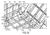
次に、図9および図10を参照して、タンクの角部における一次封止膜の構造を説明する。 Next, the structure of the primary sealing film at the corner of the tank will be described with reference to FIGS. 9 and 10. FIG.
一次封止膜は、例えば、互いに垂直な2つの一連の波形を有する膜である。実質的に国際公開第2017/006044号パンフレットに記載のとおりに製作することが可能である。エッジ角部に隣接する一次封止膜の金属シート67が、エッジ角部の方を向いたそれぞれのエッジに沿って、金属製コーナーピース32、232、65、132に溶接される。さらに、金属製コーナー部品68、168、268が、2つの連続する金属製コーナーピース32、232、65、132の間の各々の界面をまたぐ様相で溶接される。
A primary sealing membrane is, for example, a membrane having two series of corrugations perpendicular to each other. It can be manufactured substantially as described in WO2017/006044 pamphlet.
コーナー部品68、168、268は、オリフィス37、137、237を覆い、金属製コーナーピースの切り欠き54、254は、エッジ角部10に対して垂直に向けられた一次封止膜の波形の連続性をもたらす。
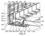
次に、図13~図16を参照して、エッジ角部10の端部におけるタンクの壁の構造の第2の実施形態を説明する。この実施形態において、図13の斜視図に示される最後から2番目の一次角部構造物1230は、この最後から2番目の一次角部構造物1230が取り付けられた後に第2の金属製コーナーピース1065(図16)をタンクの内側から取り付けることができるように、変更されている。
A second embodiment of the construction of the tank wall at the end of the
この目的のために、最後から2番目の一次角部構造物1230のうちの最後の一次角部構造物130に面する側において、二平面断熱ブロック231の2つの面は、エッジ角部10に平行に延びるそれぞれの溝83を有し、溝83は、内側シート235の内面へと開き、かつ内側シート235のうちの最後の一次角部構造物130に面する側において開いている。溝83は、内面から厚さ方向に沿って増大する幅を有し、すなわち図示の実施形態において、溝83は、より狭い入口部分とより広い底部分とを連続的に有する。
For this purpose, on the side facing the last
図14に斜視図にて示されているインサート84が、溝83にスライドの様相で収容される。インサート84は、溝83の底部分に収容されるように意図されたより広い基部85と、溝83の入口部分に収容されるように意図されたより狭い頭部86とを備える輪郭付けられた全体形状を有する。頭部86は、その上面に、固定ねじ88(図16)を受け入れるためのねじ穴87を有する。好ましくは、インサート84は、エッジ角部10を横切る方向にも調整すき間を可能にするために、溝83よりもわずかに狭い。
An
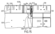
図15および図16は、一次封止膜が取り付けられる前のエッジ角部の部に位置するタンクの壁の領域を示している。図15は、最後の平坦な一次断熱パネル129に関する上方からの平面図である。最後から2番目の一次角部構造物1230が、第2の金属製コーナーピース1065が存在していない状態で、二次断熱バリアに取り付けられていることが示されている。したがって、これにより、最後の一次角部構造物130と最後から2番目の一次角部構造物1230との間の空間138へのアクセスが自由である。上部からのこのアクセスにより、図15に示されるように、最後の平坦な一次断熱パネル129の下部シートの露出領域128を支えるために、伸長位置における支え棒150の位置を容易に調整し、ナット145を締め込むことによって動かぬように固定することが可能になる。
Figures 15 and 16 show the areas of the tank wall located at the edge corners before the primary sealing membrane is applied. FIG. 15 is a top plan view of the last flat
次に、一次断熱バリアを補完するために、断熱ライニング(図示せず)が空間138および凹部127に配置され、次いで、図16に示されるように、第2の金属製コーナーピース1065が最後から2番目の一次角部構造物1230に取り付けられる。このために、固定ねじ88が、第2の金属製コーナーピース1065の2つの面のそれぞれのドリル穴に挿入され、インサート84のねじ穴87にねじ込まれる。あるいは、リベットを使用することも可能である。
Next, an insulating lining (not shown) is placed in space 138 and
次いで、一次膜を上述のように実現することができる。 The primary membrane can then be realized as described above.
タンクの内側から取り付けられる金属製コーナーピース1065により、アンカー部材への容易なアクセスを提供することが可能になる。この解決策は、さまざまな形態で作られたアンカー部材と共に使用することができる。
A
図11が、エッジ角部10に沿ったタンクの壁の別の実施形態を示している。図を単純にするために、一次および二次封止膜は省略されている。図2~図4の要素と同様または同一の要素は、300だけ増やした同じ参照符号を有しており、図2~図4の要素と異なる限りにおいて説明される。
FIG. 11 shows another embodiment of the tank wall along the
この実施形態において、一次角部構造物330は、2つの二平面断熱ブロック331の間の各々の空間338に配置されたピン345によって、二次角部構造物313に固定される。この目的のために、剛体シート334は、剛体シート334の2つの横リムが露出するように、ポリマー発泡体層333よりもわずかに幅広い。
In this embodiment, the primary corner structure 330 is secured to the
支え棒350は、ピン345が通過する長円形であってよいドリル穴を有し、間にピン345が配置された2つの一次角部構造物330の剛体シート334の横リムを支える。したがって、各々の一次角部構造物330は、その剛体シート334の2つの横リムに係合する2つの支え棒350によって保持される。支え棒350を荷重支持構造物の方向に締め付けるために、ナット(図示せず)が各々のピン345へとねじ込まれる。金属製コーナーピース332のエッジの切り欠き354が、ピン345の取り付け、およびその後の上述のやり方でのナットの取り付けをより容易にする。
The
一次角部構造物330を固定するこのやり方ゆえに、金属製コーナーピース332にオリフィスが存在せず、したがって金属製コーナーピース332を連続的にすることができる。
Because of this way of securing the primary corner structure 330, there are no orifices in the
一次角部構造物330の列に隣接する平坦な一次断熱パネル329を二次バリアに固定するために、ピン69の列を、一次角部構造物330の列の両側に設けることができる。これにより、図示のように、より広い二次角部構造物313を用意することが必要になる可能性がある。
Rows of
図示されていない図11の変種においては、ピン69が存在せず、支え棒350が、一次角部構造物330および平坦な一次断熱パネル329にまたがる伸長位置へと配置されて、これら2つの断熱要素の結合固定を保証するように、図6の支え棒50と同じやり方でスライド可能にされる。この目的のために、支え棒350の長さを増やすことができ、平坦な一次断熱パネル329の形状を、支え棒350が下部シートを露出させる溝または凹部に受け入れられるように調整することができる。
In the variant of FIG. 11, not shown, there are no
一実施形態においては、二次断熱バリアおよび二次封止膜が存在せず、一次断熱バリアを固定するピンが、荷重支持壁11、12によって直接支持される。
In one embodiment, the secondary insulating barrier and secondary sealing membrane are absent and the pins that secure the primary insulating barrier are directly supported by the
流体を貯蔵するための密閉断熱タンクを製造するための上述の技術は、例えば陸上設備あるいはメタンタンカーなどの浮体構造物におけるLNG貯蔵槽の形成など、さまざまな種類の貯蔵槽において使用可能である。 The techniques described above for manufacturing closed and insulated tanks for storing fluids can be used in various types of storage tanks, for example forming LNG storage tanks in land-based installations or floating structures such as methane tankers.
平坦な部分がエッジ角部において出会う実際に多面体である支持面の文脈において上述した技術は、平坦な部分の間の接続部を形成する丸みを帯びた部分をエッジ角部の代わりに有するおおむね多面体である支持面にも適用可能である。エッジ角部領域という用語が、両方の文脈において2つの平坦な部分の間の接続部を指して使用され、実際のエッジ角部または2つの平坦な部分の間の丸みを帯びた部分に対応できる。 The techniques described above in the context of support surfaces that are actually polyhedral where flat portions meet at edge corners are generally polyhedral with instead of edge corners rounded portions forming connections between flat portions. It is also applicable to support surfaces that are The term edge corner region is used in both contexts to refer to the connection between two flat portions and can correspond to the actual edge corner or the rounded portion between the two flat portions. .
図12を参照すると、メタンタンカー70の切断図が、船舶の二重船体72内に取り付けられた角柱の全体形状を有する密閉断熱タンク71を示している。タンク71の壁は、タンクに収容されたLNGに接触するように意図された一次封止バリア、一次封止バリアと船舶の二重船体72との間に配置された二次封止バリア、ならびに一次封止バリアと二次封止バリアとの間および二次封止バリアと二重船体72との間にそれぞれ配置された2つの断熱バリアを有する。
Referring to FIG. 12, a cutaway view of a
それ自体は既知のやり方で、船舶の上甲板に配置された積み込み/積み下ろしパイプライン73を、適切なコネクタによって海上または港のターミナルへと接続し、積み荷であるLNGをタンク71から移し、あるいはタンク71へと移すことができる。
In a manner known per se, a loading/
図12は、積み込みおよび積み下ろしステーション75と、海中パイプ76と、陸上設備77とを有する海上ターミナルの例を示している。積み込みおよび積み下ろしステーション75は、可動アーム74と、可動アーム74を支持するタワー78とを有する沖合の固定設備である。可動アーム74は、積み込み/積み下ろしパイプライン73へと接続することができる断熱可撓ホース79の束を保持する。向きを変えることができる可動アーム74は、あらゆるサイズのメタンタンカーに適合する。接続パイプ(図示せず)が、タワー78の内部を延びている。積み込みおよび積み下ろしステーション75は、陸上設備77からメタンタンカー70への積み込み、または陸上設備77へのメタンタンカー70からの積み下ろしを可能にする。陸上設備77は、液化ガス貯蔵タンク80と、水中パイプ76によって積み込みおよび積み下ろしステーション75に接続された接続パイプ81とを有する。水中パイプ76は、積み込みまたは積み下ろしステーション75と陸上設備77との間で液化ガスを例えば5kmなどの長距離にわたって移送することを可能にし、メタンタンカー70を積み込みおよび積み下ろし作業の際に海岸から長距離に保つことを可能にする。
FIG. 12 shows an example of a marine terminal with loading and unloading
液化ガスの移送に必要な圧力を生成するために、船舶70に搭載されたポンプおよび/または陸上設備77に設けられたポンプならびに/あるいは積み込みおよび積み下ろしステーション75に設けられたポンプが使用される。
Pumps onboard the
本発明をいくつかの特定の実施形態に関して説明してきたが、本発明が、決してそれらの実施形態に限定されず、本発明が、上述した手段のあらゆる技術的同等物およびそれらのあらゆる組み合わせを、それらが本発明の技術的範囲に包含されるならば含むことは、明らかである。 Although the invention has been described with respect to some specific embodiments, the invention is by no means limited to those embodiments, and the invention includes all technical equivalents of the above means and any combination thereof, It is expressly included if they are within the scope of the present invention.
動詞「・・・を有する」、「・・・を備える」、または「・・・を含む」、ならびにその活用形の使用は、請求項に記載された要素またはステップ以外の他の要素またはステップの存在を排除しない。要素またはステップについての不定冠詞「或る・・・」または「1つの・・・」の使用は、とくに明記されない限り、そのような要素またはステップが複数存在することを排除するものではない。 Use of the verbs "having," "comprising," or "including," and their conjugations, may include elements or steps other than those stated in a claim. does not rule out the existence of The use of the indefinite articles "a..." or "a..." with reference to an element or step does not exclude the presence of a plurality of such elements or steps, unless expressly stated otherwise.
請求項において、括弧内の参照符号を請求項を限定するものとして解釈すべきではない。 In the claims, any reference signs placed between parentheses shall not be construed as limiting the claim.
Claims (19)
断熱バリアと、前記断熱バリアの内面に配置された封止バリアとを有しており、前記断熱バリアは、アンカー部材を有する支持面上に配置され、前記アンカー部材によって前記支持面上に保持されており、前記支持面は、エッジ角部領域(10)において出会って互いの間に或る角度を形成する少なくとも2つの平坦な領域を有し、
前記断熱バリアは、複数の平行な列に配置された断熱要素を有し、断熱要素の第1の列は、前記支持面の前記エッジ角部領域に沿って配置された角部構造物(30、130、230、1230)の列を有し、断熱要素の第2の列は、前記支持面の前記平坦な領域上に配置された平坦な断熱パネル(29、129)の列を有し、断熱要素の前記第2の列は、断熱要素の前記第1の列に隣接し、
各前記角部構造物(30、130、230、1230)は、
前記2つの平坦な領域に平行であり、互いの間に或る角度を形成する2つの面を有しており、前記面は、前記支持面の対応する平坦な領域に押し付けられる平坦な外側表面と、前記対応する平坦な領域に平行かつ前記平坦な外側表面から厚さ方向に離れている平坦な内側表面とを含む二平面断熱ブロック(31、131、231)と、
前記支持面の前記エッジ角部領域に整列した前記封止バリアを形成するために、前記二平面断熱ブロックの前記平坦な内側表面に取り付けられた金属製コーナーピース(32、232、65、1065、132)と
を有し、
前記金属製コーナーピースは、前記エッジ角部領域の方向に沿って前記二平面断熱ブロックよりも突出する突出部分(53、153、253)を有しており、
断熱要素の前記第1の列における第1の角部構造物(1230)と第2の角部構造物(130)とは、前記二平面断熱ブロックの間に前記エッジ角部領域の方向に沿った空間(138)を呈するように連続的に配置され、前記空間は、前記第1の角部構造物(1230)の前記金属製コーナーピース(1065)の前記突出部分(253)によって少なくとも部分的に覆われ、
前記空間を覆う突出部分(253)を有する前記金属製コーナーピース(1065)は、前記金属製コーナーピースを前記第1の角部構造物(1230)の前記二平面断熱ブロックに取り付けるために、前記二平面断熱ブロックに係合するように意図された取り付け部材(88)を受け入れるためのドリル穴を内面に有し、前記取り付け部材を、前記金属製コーナーピース(1065)の前記内面から前記ドリル穴へと挿入することができ、
前記アンカー部材は、断熱要素の前記第1の列の第1及び第2の角部構造物(130、1230)の前記二平面断熱ブロック(131、231)の間で前記支持面上に取り付けられた支え要素(50、150)を有し、
前記支え要素(50、150)は、
前記支え要素(50、150)が、断熱要素の第2の列の場所(99)を空けるように、前記2つの角部構造物(130、1230)の間に完全に収容される後退位置と、
前記支え要素が断熱要素の前記第2の列の場所に重なり、断熱要素の前記第2の列の少なくとも1つの平坦な断熱パネル(129)に係合して、断熱要素の前記第2の列の前記平坦な断熱パネル(29、129)を前記支持面上に保持する伸長位置と
の間を、断熱要素の前記第1の列に対する横方向に前記支持面に対して移動可能である、密閉断熱タンク。 A closed and insulated tank intended to store fluids,
and a sealing barrier disposed on an inner surface of the insulation barrier, the insulation barrier disposed on a support surface having anchor members and retained on the support surface by the anchor members. and said support surface has at least two flat areas meeting at an edge corner area (10) to form an angle between each other,
Said insulating barrier comprises insulating elements arranged in a plurality of parallel rows, a first row of insulating elements being corner structures (30) arranged along said edge corner regions of said support surface. , 130, 230, 1230), a second row of insulating elements comprising a row of flat insulating panels (29, 129) positioned on said flat area of said support surface; said second row of insulating elements is adjacent to said first row of insulating elements;
each said corner structure (30, 130, 230, 1230) comprising:
having two faces parallel to said two flat regions and forming an angle between each other, said faces being flat outer surfaces pressed against corresponding flat regions of said support surface; and a planar inner surface parallel to said corresponding planar region and spaced through its thickness from said planar outer surface;
metal corner pieces (32, 232, 65, 1065, 32, 232, 65, 1065; 132) and
has
The metal corner piece has a protruding portion (53, 153, 253) that protrudes beyond the biplanar insulation block along the direction of the edge corner region,
A first corner structure (1230) and a second corner structure (130) in said first row of insulation elements are positioned between said biplanar insulation blocks along said edge corner region direction. space (138) at least partially defined by said projecting portion (253) of said metal corner piece (1065) of said first corner structure (1230). covered with
Said metal corner piece (1065) having a protruding portion (253) covering said space is used to attach said metal corner piece to said biplanar insulation block of said first corner structure (1230). The inner surface has a drilled hole for receiving a mounting member (88) intended to engage a biplanar insulation block, said mounting member being inserted into said drilled hole from said inner surface of said metal corner piece (1065). can be inserted into
Said anchor members are on said support surface between said biplanar insulation blocks (131, 231) of first and second corner structures (1 30 , 1 230) of said first row of insulation elements. having an attached support element (50, 150);
Said support element (50, 150) comprises:
a setback in which said support elements (50, 150) are fully accommodated between said two corner structures (1 30 , 1 230) so as to clear the location (99) of the second row of insulating elements; location and,
said support element overlies the location of said second row of insulating elements and engages at least one flat insulating panel (129) of said second row of insulating elements to provide said second row of insulating elements and an extended position holding said flat insulation panel (29, 129) on said support surface of said support surface in a lateral direction with respect to said first row of insulation elements . insulated tank.
前記支持面に取り付けられ、断熱要素の前記第1の列の前記第1及び第2の角部構造物(130、1230)の間の空間へと内向きに突出するピン(45、145)と、
前記ピンにねじ込まれ、前記支え要素(50、150)を前記支持面の方向に締め付けて、前記支え要素の位置を固定することができるナット(47)と
をさらに有する、請求項1に記載のタンク。 The anchor member is
pins (45, 145) attached to said support surface and projecting inwardly into the space between said first and second corner structures (1 30 , 1 230) of said first row of insulating elements; )and,
2. The nut (47) according to claim 1, further comprising a nut (47) screwed onto the pin and capable of tightening the bearing element (50, 150) in the direction of the bearing surface to fix the position of the bearing element. tank.
前記支え棒(50、150)が前記第1及び第2の角部構造物(130、1230)の間に完全に収容される前記後退位置と、
前記支え棒の一部分(51)が断熱要素の前記第1の列よりも突出して、断熱要素の前記第2の列の前記少なくとも1つの断熱要素(29、129)と係合する前記伸長位置と
の間で、断熱要素の前記第1の列に対する横方向にスライドさせることができる、請求項2に記載のタンク。 The support element has a support bar (50, 150) with a slot (58, 158) through which the pin (45, 145) passes, and when the nut is not tightened on the support bar,
said retracted position in which said support bar (50, 150) is fully received between said first and second corner structures (130 , 1230 );
said extended position in which a portion (51) of said support bar protrudes beyond said first row of insulating elements to engage said at least one insulating element (29, 129) of said second row of insulating elements; 3. The tank according to claim 2, wherein the tank can be slid laterally with respect to said first row of insulating elements between.
前記支え要素は、断熱要素の前記第2の列の前記平坦な断熱パネル(29、129)のそれぞれの領域に係合して、前記平坦な断熱パネルを前記支持面上に保持する、請求項1~5のいずれか一項に記載のタンク。 Said support surface carries a plurality of anchor members (45, 145) distributed along said first row of insulating elements, said anchor members (45, 145) being aligned with said insulating elements of said first row. a support element (50, 150) mounted on said support surface between (30, 130, 230, 1230) and movable relative to said support surface between said retracted position and said extended position; have
4. The support elements of claim 1, wherein said support elements engage respective regions of said flat insulation panels (29, 129) of said second row of insulation elements to retain said flat insulation panels on said support surface. A tank according to any one of 1 to 5.
前記角部構造物の列の前記最後から2番目の角部構造物(230)の前記二平面断熱ブロック(231)は、前記エッジ角部領域の中央部分に沿って位置する角部構造物よりも、前記エッジ角部領域の方向に沿った寸法が大きく、前記最後から2番目の角部構造物の前記金属製コーナーピースは、前記エッジ角部領域の方向に沿って並置されかつ前記二平面断熱ブロック(231)の前記平坦な内面に取り付けられた2つのコーナーピース部分(232、1065)で構成され、
前記最後から2番目の角部構造物の第1のコーナーピース部分(232)は、前記第1のコーナーピース部分の外面に位置し、前記第1のコーナーピース部分の内面からはアクセスできない取り付け部材によって、前記二平面断熱ブロック(231)に取り付けられ、
前記エッジ角部領域の前記端部側に位置する前記最後から2番目の角部構造物の第2のコーナーピース部分(1065)は、前記第2のコーナーピース部分(1065)を前記角部構造物の前記二平面断熱ブロックへと取り付けるべく前記二平面断熱ブロック(231)に係合するように意図された前記取り付け部材を受け入れるための前記ドリル穴を内面に有し、前記取り付け部材を、前記第2のコーナーピース部分(1065)の前記内面から前記ドリル穴へと挿入することができる、請求項1~12のいずれか一項に記載のタンク。 Said support surface has at one end of said edge corner region (10) a third flat region transverse to said edge corner region, the last corner structure of said row of corner structures. (130) has, in addition to said biplanar insulation block, a third face (100) parallel to said third planar region and forming an angle with said two faces of said biplanar insulation block (130); death,
The biplanar insulation block (231) of the penultimate corner structure (230) of the row of corner structures is more dense than the corner structures located along the central portion of the edge corner region. Also, the dimension along the direction of the edge corner region is large, and the metal corner pieces of the penultimate corner structure are juxtaposed along the direction of the edge corner region and the biplanar consisting of two corner piece portions (232, 1065) attached to said flat inner surface of an insulating block (231),
A first corner piece portion (232) of said penultimate corner structure is located on an outer surface of said first corner piece portion and is not accessible from an inner surface of said first corner piece portion. attached to said biplanar insulation block (231) by
A second corner piece portion (1065) of said penultimate corner structure, located on said end side of said edge corner region, connects said second corner piece portion (1065) to said corner structure. having on its inner surface said drilled hole for receiving said mounting member intended to engage said bi-planar insulation block (231) for attachment to said bi-planar insulation block of an object, said mounting member A tank according to any one of the preceding claims, wherein it can be inserted from said inner surface of the second corner piece part ( 1065 ) into said drilled hole.
二重船体(72)と、前記二重船体内に配置された請求項1~15のいずれか一項に記載のタンク(71)とを有する船舶。 A vessel (70) for transporting a fluid, comprising:
A ship comprising a double hull (72) and a tank (71) according to any one of the preceding claims arranged in said double hull.
請求項16に記載の船舶(70)と、前記船舶の前記船体内に設置された前記タンク(71)を水上または陸上の貯蔵設備(77)へと接続するように配置された断熱パイプライン(73、79、76、81)と、流体を前記断熱パイプラインを通って前記水上または陸上の貯蔵設備から前記船舶の前記タンクへと運び、あるいは前記船舶の前記タンクから前記水上または陸上の貯蔵システムへと運ぶためのポンプとを有するシステム。 A system for transporting a fluid, comprising:
17. A vessel (70) according to claim 16 and an insulated pipeline (77) arranged to connect said tank (71) located in said hull of said vessel to a water or land storage facility (77). 73; and a pump for delivering to.
支持面を用意するステップと、
前記支持面に対して移動できる様相で取り付けられる支え要素(50、150)を有しているアンカー部材を、前記支持面上に取り付けるステップと、
断熱要素(30、130、230、1230)の前記第1の列を、前記支え要素(50、150)が前記断熱要素の第1の列の2つの断熱要素の間に完全に収容され、かつ前記支え要素が断熱要素の前記第1の列に対して横方向に移動可能に取り付けられるように、前記支持面上に取り付けるステップと、
断熱要素の前記第1の列に平行かつ断熱要素の前記第1の列に隣接する断熱要素(29、129)の第2の列を、前記支持面上に配置するステップと、
前記支え要素(50、150)を、前記支え要素が断熱要素の前記第2の列の場所(99)に重なり、断熱要素の前記第2の列の少なくとも1つの断熱要素(29、129)に係合して、断熱要素の前記第2の列の前記断熱要素を前記支持面上に保持するように、伸長位置へと移動させるステップと、
前記支え要素を前記伸長位置に固定するステップと、
前記金属製コーナーピース(1065)を取り付けるステップと、
前記取り付け部材(88)を、前記金属製コーナーピース(1065)のドリル穴へ挿入するステップと、
を有する製造方法。 A manufacturing method for manufacturing the closed and insulated tank according to any one of claims 1 to 15 ,
providing a support surface;
mounting on said support surface an anchor member having a support element (50, 150) mounted in a movable manner relative to said support surface;
said first row of insulating elements (30, 130, 230, 1230), said support elements (50, 150) being completely housed between two insulating elements of said first row of insulating elements, and mounting on the support surface such that the support element is laterally movably mounted with respect to the first row of insulating elements ;
placing a second row of insulating elements (29, 129) parallel to and adjacent to said first row of insulating elements on said support surface;
said support element (50, 150) overlying at least one insulation element (29, 129) of said second row of insulation elements , said support element overlapping a location (99) of said second row of insulation elements; moving into an extended position to engage and retain the insulating elements of the second row of insulating elements on the support surface;
fixing the support element in the extended position ;
attaching the metal corner piece (1065);
inserting the mounting member (88) into a drilled hole in the metal corner piece (1065);
A manufacturing method having
Applications Claiming Priority (3)
| Application Number | Priority Date | Filing Date | Title |
|---|---|---|---|
| FR1760382A FR3073271B1 (en) | 2017-11-06 | 2017-11-06 | SEALED AND THERMALLY INSULATED TANK |
| FR1760382 | 2017-11-06 | ||
| PCT/FR2018/052669 WO2019086788A1 (en) | 2017-11-06 | 2018-10-26 | Sealed and thermally insulating tank |
Publications (2)
| Publication Number | Publication Date |
|---|---|
| JP2021501860A JP2021501860A (en) | 2021-01-21 |
| JP7334152B2 true JP7334152B2 (en) | 2023-08-28 |
Family
ID=61027907
Family Applications (1)
| Application Number | Title | Priority Date | Filing Date |
|---|---|---|---|
| JP2020524606A Active JP7334152B2 (en) | 2017-11-06 | 2018-10-26 | Hermetically sealed insulated tank |
Country Status (12)
| Country | Link |
|---|---|
| EP (1) | EP3707423B1 (en) |
| JP (1) | JP7334152B2 (en) |
| KR (1) | KR102487422B1 (en) |
| CN (1) | CN111587341B (en) |
| DK (1) | DK3707423T3 (en) |
| ES (1) | ES2957301T3 (en) |
| FR (1) | FR3073271B1 (en) |
| MY (1) | MY197460A (en) |
| PT (1) | PT3707423T (en) |
| RU (1) | RU2764345C2 (en) |
| SG (1) | SG11202004103SA (en) |
| WO (1) | WO2019086788A1 (en) |
Families Citing this family (2)
| Publication number | Priority date | Publication date | Assignee | Title |
|---|---|---|---|---|
| FR3102533B1 (en) * | 2019-10-25 | 2023-12-22 | Gaztransport Et Technigaz | Device and method for manufacturing a waterproof and thermally insulating tank corner structure |
| FR3133900B1 (en) | 2022-03-28 | 2024-07-12 | Gaztransport Et Technigaz | Waterproof and thermally insulating tank |
Citations (3)
| Publication number | Priority date | Publication date | Assignee | Title |
|---|---|---|---|---|
| WO2016046487A1 (en) | 2014-09-26 | 2016-03-31 | Gaztransport Et Technigaz | Sealed and insulating vessel comprising a bridging element between the panels of the secondary insulation barrier |
| JP2016520770A (en) | 2013-04-12 | 2016-07-14 | ギャズトランスポルト エ テクニギャズ | Angular structure of hermetically insulated tank for storing fluid |
| WO2017006044A1 (en) | 2015-07-06 | 2017-01-12 | Gaztransport Et Technigaz | Sealed and thermally insulated tank having a secondary sealing membrane equipped with a corner arrangement with corrugated metal sheets |
Family Cites Families (11)
| Publication number | Priority date | Publication date | Assignee | Title |
|---|---|---|---|---|
| SU1432307A1 (en) * | 1987-01-19 | 1988-10-23 | Всесоюзный Научно-Исследовательский И Проектный Институт "Теплопроект" | Thermal insulation structure of isothermic reservoir |
| FR2813111B1 (en) | 2000-08-18 | 2002-11-29 | Gaz Transport & Technigaz | WATERPROOF AND THERMALLY INSULATING TANK IMPROVED LONGITUDINAL AREAS |
| KR100499710B1 (en) * | 2004-12-08 | 2005-07-05 | 한국가스공사 | Lng storage tank installed inside the ship and manufacturing method the tank |
| KR20090115644A (en) * | 2008-05-02 | 2009-11-05 | 삼성중공업 주식회사 | Apparatus for fixing a insulation panel of a cargo and insulation panel thereof |
| WO2009134099A2 (en) * | 2008-05-02 | 2009-11-05 | 삼성중공업 주식회사 | Fixing device for cargo hold insulation panel and insulation panel using the fixing device |
| FR2977562B1 (en) * | 2011-07-06 | 2016-12-23 | Gaztransport Et Technigaz | SEALED AND THERMALLY INSULATING TANK INTEGRATED IN A CARRIER STRUCTURE |
| FR2984992B1 (en) * | 2011-12-21 | 2015-03-27 | Gaztransp Et Technigaz | WATERPROOF AND INSULATED TANK WITH RESTRAINT DEVICE |
| FR3004510B1 (en) * | 2013-04-12 | 2016-12-09 | Gaztransport Et Technigaz | SEALED AND THERMALLY INSULATING TANK FOR STORAGE OF A FLUID |
| RU2600419C1 (en) * | 2015-08-13 | 2016-10-20 | Общество с ограниченной ответственностью проектно-конструкторское бюро "БАЛТМАРИН" | Membrane tank for liquefied natural gas (vm type) |
| FR3042253B1 (en) | 2015-10-13 | 2018-05-18 | Gaztransport Et Technigaz | SEALED AND THERMALLY INSULATED TANK |
| KR101792479B1 (en) * | 2016-03-04 | 2017-11-03 | 삼성중공업 주식회사 | CORNER PANEL ASSEMBLY AND construction method FOR LNG CARGO USING THE SAME |
-
2017
- 2017-11-06 FR FR1760382A patent/FR3073271B1/en active Active
-
2018
- 2018-10-26 RU RU2020114932A patent/RU2764345C2/en active
- 2018-10-26 ES ES18801022T patent/ES2957301T3/en active Active
- 2018-10-26 JP JP2020524606A patent/JP7334152B2/en active Active
- 2018-10-26 DK DK18801022.7T patent/DK3707423T3/en active
- 2018-10-26 KR KR1020207016292A patent/KR102487422B1/en active IP Right Grant
- 2018-10-26 SG SG11202004103SA patent/SG11202004103SA/en unknown
- 2018-10-26 EP EP18801022.7A patent/EP3707423B1/en active Active
- 2018-10-26 PT PT188010227T patent/PT3707423T/en unknown
- 2018-10-26 WO PCT/FR2018/052669 patent/WO2019086788A1/en unknown
- 2018-10-26 CN CN201880084667.0A patent/CN111587341B/en active Active
- 2018-10-26 MY MYPI2020002232A patent/MY197460A/en unknown
Patent Citations (4)
| Publication number | Priority date | Publication date | Assignee | Title |
|---|---|---|---|---|
| JP2016520770A (en) | 2013-04-12 | 2016-07-14 | ギャズトランスポルト エ テクニギャズ | Angular structure of hermetically insulated tank for storing fluid |
| WO2016046487A1 (en) | 2014-09-26 | 2016-03-31 | Gaztransport Et Technigaz | Sealed and insulating vessel comprising a bridging element between the panels of the secondary insulation barrier |
| JP2017530064A (en) | 2014-09-26 | 2017-10-12 | ギャズトランスポルト エ テクニギャズ | Sealed insulated container with bridging elements between the panels of the secondary insulation barrier |
| WO2017006044A1 (en) | 2015-07-06 | 2017-01-12 | Gaztransport Et Technigaz | Sealed and thermally insulated tank having a secondary sealing membrane equipped with a corner arrangement with corrugated metal sheets |
Also Published As
| Publication number | Publication date |
|---|---|
| KR20200085826A (en) | 2020-07-15 |
| MY197460A (en) | 2023-06-19 |
| WO2019086788A1 (en) | 2019-05-09 |
| RU2020114932A (en) | 2021-12-08 |
| KR102487422B1 (en) | 2023-01-11 |
| SG11202004103SA (en) | 2020-06-29 |
| CN111587341B (en) | 2022-04-29 |
| FR3073271B1 (en) | 2019-11-01 |
| RU2020114932A3 (en) | 2021-12-20 |
| JP2021501860A (en) | 2021-01-21 |
| RU2764345C2 (en) | 2022-01-17 |
| EP3707423A1 (en) | 2020-09-16 |
| PT3707423T (en) | 2023-09-05 |
| EP3707423B1 (en) | 2023-07-05 |
| ES2957301T3 (en) | 2024-01-16 |
| FR3073271A1 (en) | 2019-05-10 |
| DK3707423T3 (en) | 2023-10-09 |
| CN111587341A (en) | 2020-08-25 |
Similar Documents
| Publication | Publication Date | Title |
|---|---|---|
| CN108603634B (en) | Heat insulation sealing tank | |
| US10415755B2 (en) | Sealed and thermally insulated tank having a secondary sealing membrane equipped with a corner arrangement with corrugated metal sheets | |
| CN107110428B (en) | Sealed insulation tank comprising bridging elements between panels of a secondary insulation barrier | |
| KR102624276B1 (en) | Insulating blocks suitable for manufacturing insulating walls in sealed tanks | |
| JP7241777B2 (en) | Insulated sealed tank | |
| KR102512422B1 (en) | insulated sealed tank | |
| AU2014252958B2 (en) | Sealed and thermally insulating tank for storing a fluid | |
| JP7154292B2 (en) | Hermetically sealed insulated tank | |
| CN109630879B (en) | Method for installing an anchoring device for a sealed and insulated tank | |
| KR102389246B1 (en) | Corner structure of sealed and insulated tank and assembly method thereof | |
| KR102580155B1 (en) | Method for manufacturing a heat insulating barrier for a ship wall and a heat insulating barrier manufactured thereby | |
| ES2928289T3 (en) | Watertight and thermally insulated tank | |
| CN112313443B (en) | Heat insulation sealing tank | |
| JP7334152B2 (en) | Hermetically sealed insulated tank | |
| JP7354158B2 (en) | Closed insulated tank |
Legal Events
| Date | Code | Title | Description |
|---|---|---|---|
| A621 | Written request for application examination |
Free format text: JAPANESE INTERMEDIATE CODE: A621 Effective date: 20211005 |
|
| A977 | Report on retrieval |
Free format text: JAPANESE INTERMEDIATE CODE: A971007 Effective date: 20220909 |
|
| A131 | Notification of reasons for refusal |
Free format text: JAPANESE INTERMEDIATE CODE: A131 Effective date: 20221101 |
|
| A601 | Written request for extension of time |
Free format text: JAPANESE INTERMEDIATE CODE: A601 Effective date: 20230130 |
|
| A521 | Request for written amendment filed |
Free format text: JAPANESE INTERMEDIATE CODE: A523 Effective date: 20230329 |
|
| TRDD | Decision of grant or rejection written | ||
| A01 | Written decision to grant a patent or to grant a registration (utility model) |
Free format text: JAPANESE INTERMEDIATE CODE: A01 Effective date: 20230725 |
|
| A61 | First payment of annual fees (during grant procedure) |
Free format text: JAPANESE INTERMEDIATE CODE: A61 Effective date: 20230816 |
|
| R150 | Certificate of patent or registration of utility model |
Ref document number: 7334152 Country of ref document: JP Free format text: JAPANESE INTERMEDIATE CODE: R150 |