JP7292060B2 - Y2O3-ZrO2 Erosion Resistant Materials for Chamber Components in Plasma Environments - Google Patents
Y2O3-ZrO2 Erosion Resistant Materials for Chamber Components in Plasma Environments Download PDFInfo
- Publication number
- JP7292060B2 JP7292060B2 JP2019042015A JP2019042015A JP7292060B2 JP 7292060 B2 JP7292060 B2 JP 7292060B2 JP 2019042015 A JP2019042015 A JP 2019042015A JP 2019042015 A JP2019042015 A JP 2019042015A JP 7292060 B2 JP7292060 B2 JP 7292060B2
- Authority
- JP
- Japan
- Prior art keywords
- mol
- zro
- ceramic material
- chamber component
- sintered ceramic
- Prior art date
- Legal status (The legal status is an assumption and is not a legal conclusion. Google has not performed a legal analysis and makes no representation as to the accuracy of the status listed.)
- Active
Links
Images


Classifications
-
- C—CHEMISTRY; METALLURGY
- C04—CEMENTS; CONCRETE; ARTIFICIAL STONE; CERAMICS; REFRACTORIES
- C04B—LIME, MAGNESIA; SLAG; CEMENTS; COMPOSITIONS THEREOF, e.g. MORTARS, CONCRETE OR LIKE BUILDING MATERIALS; ARTIFICIAL STONE; CERAMICS; REFRACTORIES; TREATMENT OF NATURAL STONE
- C04B35/00—Shaped ceramic products characterised by their composition; Ceramics compositions; Processing powders of inorganic compounds preparatory to the manufacturing of ceramic products
- C04B35/50—Shaped ceramic products characterised by their composition; Ceramics compositions; Processing powders of inorganic compounds preparatory to the manufacturing of ceramic products based on rare-earth compounds
- C04B35/505—Shaped ceramic products characterised by their composition; Ceramics compositions; Processing powders of inorganic compounds preparatory to the manufacturing of ceramic products based on rare-earth compounds based on yttrium oxide
-
- C—CHEMISTRY; METALLURGY
- C04—CEMENTS; CONCRETE; ARTIFICIAL STONE; CERAMICS; REFRACTORIES
- C04B—LIME, MAGNESIA; SLAG; CEMENTS; COMPOSITIONS THEREOF, e.g. MORTARS, CONCRETE OR LIKE BUILDING MATERIALS; ARTIFICIAL STONE; CERAMICS; REFRACTORIES; TREATMENT OF NATURAL STONE
- C04B35/00—Shaped ceramic products characterised by their composition; Ceramics compositions; Processing powders of inorganic compounds preparatory to the manufacturing of ceramic products
- C04B35/622—Forming processes; Processing powders of inorganic compounds preparatory to the manufacturing of ceramic products
- C04B35/62222—Forming processes; Processing powders of inorganic compounds preparatory to the manufacturing of ceramic products obtaining ceramic coatings
-
- C—CHEMISTRY; METALLURGY
- C04—CEMENTS; CONCRETE; ARTIFICIAL STONE; CERAMICS; REFRACTORIES
- C04B—LIME, MAGNESIA; SLAG; CEMENTS; COMPOSITIONS THEREOF, e.g. MORTARS, CONCRETE OR LIKE BUILDING MATERIALS; ARTIFICIAL STONE; CERAMICS; REFRACTORIES; TREATMENT OF NATURAL STONE
- C04B35/00—Shaped ceramic products characterised by their composition; Ceramics compositions; Processing powders of inorganic compounds preparatory to the manufacturing of ceramic products
- C04B35/622—Forming processes; Processing powders of inorganic compounds preparatory to the manufacturing of ceramic products
- C04B35/626—Preparing or treating the powders individually or as batches ; preparing or treating macroscopic reinforcing agents for ceramic products, e.g. fibres; mechanical aspects section B
- C04B35/62605—Treating the starting powders individually or as mixtures
- C04B35/62645—Thermal treatment of powders or mixtures thereof other than sintering
-
- C—CHEMISTRY; METALLURGY
- C04—CEMENTS; CONCRETE; ARTIFICIAL STONE; CERAMICS; REFRACTORIES
- C04B—LIME, MAGNESIA; SLAG; CEMENTS; COMPOSITIONS THEREOF, e.g. MORTARS, CONCRETE OR LIKE BUILDING MATERIALS; ARTIFICIAL STONE; CERAMICS; REFRACTORIES; TREATMENT OF NATURAL STONE
- C04B35/00—Shaped ceramic products characterised by their composition; Ceramics compositions; Processing powders of inorganic compounds preparatory to the manufacturing of ceramic products
- C04B35/622—Forming processes; Processing powders of inorganic compounds preparatory to the manufacturing of ceramic products
- C04B35/626—Preparing or treating the powders individually or as batches ; preparing or treating macroscopic reinforcing agents for ceramic products, e.g. fibres; mechanical aspects section B
- C04B35/63—Preparing or treating the powders individually or as batches ; preparing or treating macroscopic reinforcing agents for ceramic products, e.g. fibres; mechanical aspects section B using additives specially adapted for forming the products, e.g.. binder binders
- C04B35/638—Removal thereof
-
- C—CHEMISTRY; METALLURGY
- C04—CEMENTS; CONCRETE; ARTIFICIAL STONE; CERAMICS; REFRACTORIES
- C04B—LIME, MAGNESIA; SLAG; CEMENTS; COMPOSITIONS THEREOF, e.g. MORTARS, CONCRETE OR LIKE BUILDING MATERIALS; ARTIFICIAL STONE; CERAMICS; REFRACTORIES; TREATMENT OF NATURAL STONE
- C04B35/00—Shaped ceramic products characterised by their composition; Ceramics compositions; Processing powders of inorganic compounds preparatory to the manufacturing of ceramic products
- C04B35/622—Forming processes; Processing powders of inorganic compounds preparatory to the manufacturing of ceramic products
- C04B35/64—Burning or sintering processes
- C04B35/645—Pressure sintering
-
- C—CHEMISTRY; METALLURGY
- C04—CEMENTS; CONCRETE; ARTIFICIAL STONE; CERAMICS; REFRACTORIES
- C04B—LIME, MAGNESIA; SLAG; CEMENTS; COMPOSITIONS THEREOF, e.g. MORTARS, CONCRETE OR LIKE BUILDING MATERIALS; ARTIFICIAL STONE; CERAMICS; REFRACTORIES; TREATMENT OF NATURAL STONE
- C04B41/00—After-treatment of mortars, concrete, artificial stone or ceramics; Treatment of natural stone
- C04B41/0072—Heat treatment
-
- C—CHEMISTRY; METALLURGY
- C04—CEMENTS; CONCRETE; ARTIFICIAL STONE; CERAMICS; REFRACTORIES
- C04B—LIME, MAGNESIA; SLAG; CEMENTS; COMPOSITIONS THEREOF, e.g. MORTARS, CONCRETE OR LIKE BUILDING MATERIALS; ARTIFICIAL STONE; CERAMICS; REFRACTORIES; TREATMENT OF NATURAL STONE
- C04B41/00—After-treatment of mortars, concrete, artificial stone or ceramics; Treatment of natural stone
- C04B41/009—After-treatment of mortars, concrete, artificial stone or ceramics; Treatment of natural stone characterised by the material treated
-
- C—CHEMISTRY; METALLURGY
- C04—CEMENTS; CONCRETE; ARTIFICIAL STONE; CERAMICS; REFRACTORIES
- C04B—LIME, MAGNESIA; SLAG; CEMENTS; COMPOSITIONS THEREOF, e.g. MORTARS, CONCRETE OR LIKE BUILDING MATERIALS; ARTIFICIAL STONE; CERAMICS; REFRACTORIES; TREATMENT OF NATURAL STONE
- C04B41/00—After-treatment of mortars, concrete, artificial stone or ceramics; Treatment of natural stone
- C04B41/45—Coating or impregnating, e.g. injection in masonry, partial coating of green or fired ceramics, organic coating compositions for adhering together two concrete elements
- C04B41/50—Coating or impregnating, e.g. injection in masonry, partial coating of green or fired ceramics, organic coating compositions for adhering together two concrete elements with inorganic materials
- C04B41/5025—Coating or impregnating, e.g. injection in masonry, partial coating of green or fired ceramics, organic coating compositions for adhering together two concrete elements with inorganic materials with ceramic materials
- C04B41/5042—Zirconium oxides or zirconates; Hafnium oxides or hafnates
-
- C—CHEMISTRY; METALLURGY
- C04—CEMENTS; CONCRETE; ARTIFICIAL STONE; CERAMICS; REFRACTORIES
- C04B—LIME, MAGNESIA; SLAG; CEMENTS; COMPOSITIONS THEREOF, e.g. MORTARS, CONCRETE OR LIKE BUILDING MATERIALS; ARTIFICIAL STONE; CERAMICS; REFRACTORIES; TREATMENT OF NATURAL STONE
- C04B41/00—After-treatment of mortars, concrete, artificial stone or ceramics; Treatment of natural stone
- C04B41/53—After-treatment of mortars, concrete, artificial stone or ceramics; Treatment of natural stone involving the removal of at least part of the materials of the treated article, e.g. etching, drying of hardened concrete
-
- C—CHEMISTRY; METALLURGY
- C04—CEMENTS; CONCRETE; ARTIFICIAL STONE; CERAMICS; REFRACTORIES
- C04B—LIME, MAGNESIA; SLAG; CEMENTS; COMPOSITIONS THEREOF, e.g. MORTARS, CONCRETE OR LIKE BUILDING MATERIALS; ARTIFICIAL STONE; CERAMICS; REFRACTORIES; TREATMENT OF NATURAL STONE
- C04B41/00—After-treatment of mortars, concrete, artificial stone or ceramics; Treatment of natural stone
- C04B41/80—After-treatment of mortars, concrete, artificial stone or ceramics; Treatment of natural stone of only ceramics
- C04B41/81—Coating or impregnation
- C04B41/85—Coating or impregnation with inorganic materials
- C04B41/87—Ceramics
-
- C—CHEMISTRY; METALLURGY
- C04—CEMENTS; CONCRETE; ARTIFICIAL STONE; CERAMICS; REFRACTORIES
- C04B—LIME, MAGNESIA; SLAG; CEMENTS; COMPOSITIONS THEREOF, e.g. MORTARS, CONCRETE OR LIKE BUILDING MATERIALS; ARTIFICIAL STONE; CERAMICS; REFRACTORIES; TREATMENT OF NATURAL STONE
- C04B41/00—After-treatment of mortars, concrete, artificial stone or ceramics; Treatment of natural stone
- C04B41/80—After-treatment of mortars, concrete, artificial stone or ceramics; Treatment of natural stone of only ceramics
- C04B41/91—After-treatment of mortars, concrete, artificial stone or ceramics; Treatment of natural stone of only ceramics involving the removal of part of the materials of the treated articles, e.g. etching
-
- C—CHEMISTRY; METALLURGY
- C23—COATING METALLIC MATERIAL; COATING MATERIAL WITH METALLIC MATERIAL; CHEMICAL SURFACE TREATMENT; DIFFUSION TREATMENT OF METALLIC MATERIAL; COATING BY VACUUM EVAPORATION, BY SPUTTERING, BY ION IMPLANTATION OR BY CHEMICAL VAPOUR DEPOSITION, IN GENERAL; INHIBITING CORROSION OF METALLIC MATERIAL OR INCRUSTATION IN GENERAL
- C23C—COATING METALLIC MATERIAL; COATING MATERIAL WITH METALLIC MATERIAL; SURFACE TREATMENT OF METALLIC MATERIAL BY DIFFUSION INTO THE SURFACE, BY CHEMICAL CONVERSION OR SUBSTITUTION; COATING BY VACUUM EVAPORATION, BY SPUTTERING, BY ION IMPLANTATION OR BY CHEMICAL VAPOUR DEPOSITION, IN GENERAL
- C23C30/00—Coating with metallic material characterised only by the composition of the metallic material, i.e. not characterised by the coating process
-
- H—ELECTRICITY
- H01—ELECTRIC ELEMENTS
- H01J—ELECTRIC DISCHARGE TUBES OR DISCHARGE LAMPS
- H01J37/00—Discharge tubes with provision for introducing objects or material to be exposed to the discharge, e.g. for the purpose of examination or processing thereof
- H01J37/32—Gas-filled discharge tubes
- H01J37/32431—Constructional details of the reactor
- H01J37/32458—Vessel
- H01J37/32467—Material
-
- H—ELECTRICITY
- H01—ELECTRIC ELEMENTS
- H01J—ELECTRIC DISCHARGE TUBES OR DISCHARGE LAMPS
- H01J37/00—Discharge tubes with provision for introducing objects or material to be exposed to the discharge, e.g. for the purpose of examination or processing thereof
- H01J37/32—Gas-filled discharge tubes
- H01J37/32431—Constructional details of the reactor
- H01J37/32458—Vessel
- H01J37/32477—Vessel characterised by the means for protecting vessels or internal parts, e.g. coatings
- H01J37/32495—Means for protecting the vessel against plasma
-
- H—ELECTRICITY
- H01—ELECTRIC ELEMENTS
- H01J—ELECTRIC DISCHARGE TUBES OR DISCHARGE LAMPS
- H01J37/00—Discharge tubes with provision for introducing objects or material to be exposed to the discharge, e.g. for the purpose of examination or processing thereof
- H01J37/32—Gas-filled discharge tubes
- H01J37/32431—Constructional details of the reactor
- H01J37/32715—Workpiece holder
- H01J37/32724—Temperature
-
- H—ELECTRICITY
- H01—ELECTRIC ELEMENTS
- H01L—SEMICONDUCTOR DEVICES NOT COVERED BY CLASS H10
- H01L21/00—Processes or apparatus adapted for the manufacture or treatment of semiconductor or solid state devices or of parts thereof
- H01L21/67—Apparatus specially adapted for handling semiconductor or electric solid state devices during manufacture or treatment thereof; Apparatus specially adapted for handling wafers during manufacture or treatment of semiconductor or electric solid state devices or components ; Apparatus not specifically provided for elsewhere
- H01L21/67005—Apparatus not specifically provided for elsewhere
- H01L21/67011—Apparatus for manufacture or treatment
- H01L21/67017—Apparatus for fluid treatment
- H01L21/67063—Apparatus for fluid treatment for etching
- H01L21/67069—Apparatus for fluid treatment for etching for drying etching
-
- H—ELECTRICITY
- H01—ELECTRIC ELEMENTS
- H01L—SEMICONDUCTOR DEVICES NOT COVERED BY CLASS H10
- H01L21/00—Processes or apparatus adapted for the manufacture or treatment of semiconductor or solid state devices or of parts thereof
- H01L21/67—Apparatus specially adapted for handling semiconductor or electric solid state devices during manufacture or treatment thereof; Apparatus specially adapted for handling wafers during manufacture or treatment of semiconductor or electric solid state devices or components ; Apparatus not specifically provided for elsewhere
- H01L21/67005—Apparatus not specifically provided for elsewhere
- H01L21/67011—Apparatus for manufacture or treatment
- H01L21/67098—Apparatus for thermal treatment
- H01L21/67103—Apparatus for thermal treatment mainly by conduction
-
- H—ELECTRICITY
- H01—ELECTRIC ELEMENTS
- H01L—SEMICONDUCTOR DEVICES NOT COVERED BY CLASS H10
- H01L21/00—Processes or apparatus adapted for the manufacture or treatment of semiconductor or solid state devices or of parts thereof
- H01L21/67—Apparatus specially adapted for handling semiconductor or electric solid state devices during manufacture or treatment thereof; Apparatus specially adapted for handling wafers during manufacture or treatment of semiconductor or electric solid state devices or components ; Apparatus not specifically provided for elsewhere
- H01L21/683—Apparatus specially adapted for handling semiconductor or electric solid state devices during manufacture or treatment thereof; Apparatus specially adapted for handling wafers during manufacture or treatment of semiconductor or electric solid state devices or components ; Apparatus not specifically provided for elsewhere for supporting or gripping
- H01L21/6831—Apparatus specially adapted for handling semiconductor or electric solid state devices during manufacture or treatment thereof; Apparatus specially adapted for handling wafers during manufacture or treatment of semiconductor or electric solid state devices or components ; Apparatus not specifically provided for elsewhere for supporting or gripping using electrostatic chucks
- H01L21/6833—Details of electrostatic chucks
-
- H—ELECTRICITY
- H01—ELECTRIC ELEMENTS
- H01L—SEMICONDUCTOR DEVICES NOT COVERED BY CLASS H10
- H01L21/00—Processes or apparatus adapted for the manufacture or treatment of semiconductor or solid state devices or of parts thereof
- H01L21/67—Apparatus specially adapted for handling semiconductor or electric solid state devices during manufacture or treatment thereof; Apparatus specially adapted for handling wafers during manufacture or treatment of semiconductor or electric solid state devices or components ; Apparatus not specifically provided for elsewhere
- H01L21/683—Apparatus specially adapted for handling semiconductor or electric solid state devices during manufacture or treatment thereof; Apparatus specially adapted for handling wafers during manufacture or treatment of semiconductor or electric solid state devices or components ; Apparatus not specifically provided for elsewhere for supporting or gripping
- H01L21/687—Apparatus specially adapted for handling semiconductor or electric solid state devices during manufacture or treatment thereof; Apparatus specially adapted for handling wafers during manufacture or treatment of semiconductor or electric solid state devices or components ; Apparatus not specifically provided for elsewhere for supporting or gripping using mechanical means, e.g. chucks, clamps or pinches
- H01L21/68714—Apparatus specially adapted for handling semiconductor or electric solid state devices during manufacture or treatment thereof; Apparatus specially adapted for handling wafers during manufacture or treatment of semiconductor or electric solid state devices or components ; Apparatus not specifically provided for elsewhere for supporting or gripping using mechanical means, e.g. chucks, clamps or pinches the wafers being placed on a susceptor, stage or support
- H01L21/68757—Apparatus specially adapted for handling semiconductor or electric solid state devices during manufacture or treatment thereof; Apparatus specially adapted for handling wafers during manufacture or treatment of semiconductor or electric solid state devices or components ; Apparatus not specifically provided for elsewhere for supporting or gripping using mechanical means, e.g. chucks, clamps or pinches the wafers being placed on a susceptor, stage or support characterised by a coating or a hardness or a material
-
- C—CHEMISTRY; METALLURGY
- C04—CEMENTS; CONCRETE; ARTIFICIAL STONE; CERAMICS; REFRACTORIES
- C04B—LIME, MAGNESIA; SLAG; CEMENTS; COMPOSITIONS THEREOF, e.g. MORTARS, CONCRETE OR LIKE BUILDING MATERIALS; ARTIFICIAL STONE; CERAMICS; REFRACTORIES; TREATMENT OF NATURAL STONE
- C04B2235/00—Aspects relating to ceramic starting mixtures or sintered ceramic products
- C04B2235/02—Composition of constituents of the starting material or of secondary phases of the final product
- C04B2235/30—Constituents and secondary phases not being of a fibrous nature
- C04B2235/32—Metal oxides, mixed metal oxides, or oxide-forming salts thereof, e.g. carbonates, nitrates, (oxy)hydroxides, chlorides
- C04B2235/3224—Rare earth oxide or oxide forming salts thereof, e.g. scandium oxide
- C04B2235/3225—Yttrium oxide or oxide-forming salts thereof
-
- C—CHEMISTRY; METALLURGY
- C04—CEMENTS; CONCRETE; ARTIFICIAL STONE; CERAMICS; REFRACTORIES
- C04B—LIME, MAGNESIA; SLAG; CEMENTS; COMPOSITIONS THEREOF, e.g. MORTARS, CONCRETE OR LIKE BUILDING MATERIALS; ARTIFICIAL STONE; CERAMICS; REFRACTORIES; TREATMENT OF NATURAL STONE
- C04B2235/00—Aspects relating to ceramic starting mixtures or sintered ceramic products
- C04B2235/02—Composition of constituents of the starting material or of secondary phases of the final product
- C04B2235/30—Constituents and secondary phases not being of a fibrous nature
- C04B2235/32—Metal oxides, mixed metal oxides, or oxide-forming salts thereof, e.g. carbonates, nitrates, (oxy)hydroxides, chlorides
- C04B2235/3231—Refractory metal oxides, their mixed metal oxides, or oxide-forming salts thereof
- C04B2235/3244—Zirconium oxides, zirconates, hafnium oxides, hafnates, or oxide-forming salts thereof
-
- C—CHEMISTRY; METALLURGY
- C04—CEMENTS; CONCRETE; ARTIFICIAL STONE; CERAMICS; REFRACTORIES
- C04B—LIME, MAGNESIA; SLAG; CEMENTS; COMPOSITIONS THEREOF, e.g. MORTARS, CONCRETE OR LIKE BUILDING MATERIALS; ARTIFICIAL STONE; CERAMICS; REFRACTORIES; TREATMENT OF NATURAL STONE
- C04B2235/00—Aspects relating to ceramic starting mixtures or sintered ceramic products
- C04B2235/60—Aspects relating to the preparation, properties or mechanical treatment of green bodies or pre-forms
- C04B2235/604—Pressing at temperatures other than sintering temperatures
-
- C—CHEMISTRY; METALLURGY
- C04—CEMENTS; CONCRETE; ARTIFICIAL STONE; CERAMICS; REFRACTORIES
- C04B—LIME, MAGNESIA; SLAG; CEMENTS; COMPOSITIONS THEREOF, e.g. MORTARS, CONCRETE OR LIKE BUILDING MATERIALS; ARTIFICIAL STONE; CERAMICS; REFRACTORIES; TREATMENT OF NATURAL STONE
- C04B2235/00—Aspects relating to ceramic starting mixtures or sintered ceramic products
- C04B2235/60—Aspects relating to the preparation, properties or mechanical treatment of green bodies or pre-forms
- C04B2235/612—Machining
-
- C—CHEMISTRY; METALLURGY
- C04—CEMENTS; CONCRETE; ARTIFICIAL STONE; CERAMICS; REFRACTORIES
- C04B—LIME, MAGNESIA; SLAG; CEMENTS; COMPOSITIONS THEREOF, e.g. MORTARS, CONCRETE OR LIKE BUILDING MATERIALS; ARTIFICIAL STONE; CERAMICS; REFRACTORIES; TREATMENT OF NATURAL STONE
- C04B2235/00—Aspects relating to ceramic starting mixtures or sintered ceramic products
- C04B2235/65—Aspects relating to heat treatments of ceramic bodies such as green ceramics or pre-sintered ceramics, e.g. burning, sintering or melting processes
- C04B2235/656—Aspects relating to heat treatments of ceramic bodies such as green ceramics or pre-sintered ceramics, e.g. burning, sintering or melting processes characterised by specific heating conditions during heat treatment
-
- C—CHEMISTRY; METALLURGY
- C04—CEMENTS; CONCRETE; ARTIFICIAL STONE; CERAMICS; REFRACTORIES
- C04B—LIME, MAGNESIA; SLAG; CEMENTS; COMPOSITIONS THEREOF, e.g. MORTARS, CONCRETE OR LIKE BUILDING MATERIALS; ARTIFICIAL STONE; CERAMICS; REFRACTORIES; TREATMENT OF NATURAL STONE
- C04B2235/00—Aspects relating to ceramic starting mixtures or sintered ceramic products
- C04B2235/65—Aspects relating to heat treatments of ceramic bodies such as green ceramics or pre-sintered ceramics, e.g. burning, sintering or melting processes
- C04B2235/66—Specific sintering techniques, e.g. centrifugal sintering
- C04B2235/661—Multi-step sintering
- C04B2235/662—Annealing after sintering
-
- C—CHEMISTRY; METALLURGY
- C04—CEMENTS; CONCRETE; ARTIFICIAL STONE; CERAMICS; REFRACTORIES
- C04B—LIME, MAGNESIA; SLAG; CEMENTS; COMPOSITIONS THEREOF, e.g. MORTARS, CONCRETE OR LIKE BUILDING MATERIALS; ARTIFICIAL STONE; CERAMICS; REFRACTORIES; TREATMENT OF NATURAL STONE
- C04B2235/00—Aspects relating to ceramic starting mixtures or sintered ceramic products
- C04B2235/70—Aspects relating to sintered or melt-casted ceramic products
- C04B2235/72—Products characterised by the absence or the low content of specific components, e.g. alkali metal free alumina ceramics
-
- C—CHEMISTRY; METALLURGY
- C04—CEMENTS; CONCRETE; ARTIFICIAL STONE; CERAMICS; REFRACTORIES
- C04B—LIME, MAGNESIA; SLAG; CEMENTS; COMPOSITIONS THEREOF, e.g. MORTARS, CONCRETE OR LIKE BUILDING MATERIALS; ARTIFICIAL STONE; CERAMICS; REFRACTORIES; TREATMENT OF NATURAL STONE
- C04B2235/00—Aspects relating to ceramic starting mixtures or sintered ceramic products
- C04B2235/70—Aspects relating to sintered or melt-casted ceramic products
- C04B2235/74—Physical characteristics
- C04B2235/77—Density
-
- C—CHEMISTRY; METALLURGY
- C04—CEMENTS; CONCRETE; ARTIFICIAL STONE; CERAMICS; REFRACTORIES
- C04B—LIME, MAGNESIA; SLAG; CEMENTS; COMPOSITIONS THEREOF, e.g. MORTARS, CONCRETE OR LIKE BUILDING MATERIALS; ARTIFICIAL STONE; CERAMICS; REFRACTORIES; TREATMENT OF NATURAL STONE
- C04B2235/00—Aspects relating to ceramic starting mixtures or sintered ceramic products
- C04B2235/70—Aspects relating to sintered or melt-casted ceramic products
- C04B2235/74—Physical characteristics
- C04B2235/78—Grain sizes and shapes, product microstructures, e.g. acicular grains, equiaxed grains, platelet-structures
- C04B2235/786—Micrometer sized grains, i.e. from 1 to 100 micron
-
- C—CHEMISTRY; METALLURGY
- C04—CEMENTS; CONCRETE; ARTIFICIAL STONE; CERAMICS; REFRACTORIES
- C04B—LIME, MAGNESIA; SLAG; CEMENTS; COMPOSITIONS THEREOF, e.g. MORTARS, CONCRETE OR LIKE BUILDING MATERIALS; ARTIFICIAL STONE; CERAMICS; REFRACTORIES; TREATMENT OF NATURAL STONE
- C04B2235/00—Aspects relating to ceramic starting mixtures or sintered ceramic products
- C04B2235/70—Aspects relating to sintered or melt-casted ceramic products
- C04B2235/94—Products characterised by their shape
-
- C—CHEMISTRY; METALLURGY
- C04—CEMENTS; CONCRETE; ARTIFICIAL STONE; CERAMICS; REFRACTORIES
- C04B—LIME, MAGNESIA; SLAG; CEMENTS; COMPOSITIONS THEREOF, e.g. MORTARS, CONCRETE OR LIKE BUILDING MATERIALS; ARTIFICIAL STONE; CERAMICS; REFRACTORIES; TREATMENT OF NATURAL STONE
- C04B2235/00—Aspects relating to ceramic starting mixtures or sintered ceramic products
- C04B2235/70—Aspects relating to sintered or melt-casted ceramic products
- C04B2235/95—Products characterised by their size, e.g. microceramics
-
- C—CHEMISTRY; METALLURGY
- C04—CEMENTS; CONCRETE; ARTIFICIAL STONE; CERAMICS; REFRACTORIES
- C04B—LIME, MAGNESIA; SLAG; CEMENTS; COMPOSITIONS THEREOF, e.g. MORTARS, CONCRETE OR LIKE BUILDING MATERIALS; ARTIFICIAL STONE; CERAMICS; REFRACTORIES; TREATMENT OF NATURAL STONE
- C04B2235/00—Aspects relating to ceramic starting mixtures or sintered ceramic products
- C04B2235/70—Aspects relating to sintered or melt-casted ceramic products
- C04B2235/96—Properties of ceramic products, e.g. mechanical properties such as strength, toughness, wear resistance
- C04B2235/9607—Thermal properties, e.g. thermal expansion coefficient
-
- C—CHEMISTRY; METALLURGY
- C04—CEMENTS; CONCRETE; ARTIFICIAL STONE; CERAMICS; REFRACTORIES
- C04B—LIME, MAGNESIA; SLAG; CEMENTS; COMPOSITIONS THEREOF, e.g. MORTARS, CONCRETE OR LIKE BUILDING MATERIALS; ARTIFICIAL STONE; CERAMICS; REFRACTORIES; TREATMENT OF NATURAL STONE
- C04B2235/00—Aspects relating to ceramic starting mixtures or sintered ceramic products
- C04B2235/70—Aspects relating to sintered or melt-casted ceramic products
- C04B2235/96—Properties of ceramic products, e.g. mechanical properties such as strength, toughness, wear resistance
- C04B2235/9646—Optical properties
- C04B2235/9661—Colour
-
- C—CHEMISTRY; METALLURGY
- C04—CEMENTS; CONCRETE; ARTIFICIAL STONE; CERAMICS; REFRACTORIES
- C04B—LIME, MAGNESIA; SLAG; CEMENTS; COMPOSITIONS THEREOF, e.g. MORTARS, CONCRETE OR LIKE BUILDING MATERIALS; ARTIFICIAL STONE; CERAMICS; REFRACTORIES; TREATMENT OF NATURAL STONE
- C04B2235/00—Aspects relating to ceramic starting mixtures or sintered ceramic products
- C04B2235/70—Aspects relating to sintered or melt-casted ceramic products
- C04B2235/96—Properties of ceramic products, e.g. mechanical properties such as strength, toughness, wear resistance
- C04B2235/9669—Resistance against chemicals, e.g. against molten glass or molten salts
-
- H—ELECTRICITY
- H01—ELECTRIC ELEMENTS
- H01J—ELECTRIC DISCHARGE TUBES OR DISCHARGE LAMPS
- H01J2237/00—Discharge tubes exposing object to beam, e.g. for analysis treatment, etching, imaging
- H01J2237/32—Processing objects by plasma generation
- H01J2237/33—Processing objects by plasma generation characterised by the type of processing
- H01J2237/334—Etching
-
- H—ELECTRICITY
- H01—ELECTRIC ELEMENTS
- H01J—ELECTRIC DISCHARGE TUBES OR DISCHARGE LAMPS
- H01J2237/00—Discharge tubes exposing object to beam, e.g. for analysis treatment, etching, imaging
- H01J2237/32—Processing objects by plasma generation
- H01J2237/33—Processing objects by plasma generation characterised by the type of processing
- H01J2237/335—Cleaning
Landscapes
- Engineering & Computer Science (AREA)
- Chemical & Material Sciences (AREA)
- Ceramic Engineering (AREA)
- Manufacturing & Machinery (AREA)
- Materials Engineering (AREA)
- Organic Chemistry (AREA)
- Structural Engineering (AREA)
- Physics & Mathematics (AREA)
- Power Engineering (AREA)
- Computer Hardware Design (AREA)
- Microelectronics & Electronic Packaging (AREA)
- Condensed Matter Physics & Semiconductors (AREA)
- General Physics & Mathematics (AREA)
- Inorganic Chemistry (AREA)
- Plasma & Fusion (AREA)
- Analytical Chemistry (AREA)
- Metallurgy (AREA)
- Chemical Kinetics & Catalysis (AREA)
- Mechanical Engineering (AREA)
- Thermal Sciences (AREA)
- Compositions Of Oxide Ceramics (AREA)
- Drying Of Semiconductors (AREA)
- Ceramic Products (AREA)
- Physical Vapour Deposition (AREA)
- Chemical Vapour Deposition (AREA)
- Container, Conveyance, Adherence, Positioning, Of Wafer (AREA)
Description
本開示の諸実施形態は、概して、Y2O3及びZrO2から成る耐エロージョン性セラミック材料に関し、特には、そのような耐エロージョン性セラミック材料から製造されたチャンバ構成要素に関する。 Embodiments of the present disclosure relate generally to erosion resistant ceramic materials composed of Y2O3 and ZrO2 , and more particularly to chamber components made from such erosion resistant ceramic materials .
半導体産業では、ますますサイズが小型化している構造体を製造する多くの製造プロセスによって、デバイスは製造されている。プラズマエッチングプロセス及びプラズマクリーニングプロセスなどのいくつかの製造プロセスでは、基板を高速のプラズマ流に曝して、基板をエッチング又はクリーニングしている。プラズマは非常に腐食性が強い場合があり、処理チャンバ及びプラズマに曝される他の表面を腐食する可能性がある。 In the semiconductor industry, devices are manufactured by a number of manufacturing processes that produce structures of ever decreasing size. Some manufacturing processes, such as plasma etching processes and plasma cleaning processes, expose the substrate to a high velocity plasma stream to etch or clean the substrate. Plasmas can be very corrosive and can corrode the processing chamber and other surfaces exposed to the plasma.
一実施形態では、処理チャンバ用(例えば、半導体処理チャンバ用)のチャンバ構成要素は、Y2O3-ZrO2から実質的に構成される焼結セラミック材料から成るセラミック体を含み、セラミック材料は、55~65mol%のY2O3及び35~45mol%のZrO2から実質的に構成されている。 In one embodiment, a chamber component for a processing chamber (eg, for a semiconductor processing chamber) includes a ceramic body comprised of a sintered ceramic material consisting essentially of Y 2 O 3 —ZrO 2 , wherein the ceramic material is , 55-65 mol % Y 2 O 3 and 35-45 mol % ZrO 2 .
一実施形態では、処理チャンバ用のチャンバ構成要素は、本体と本体上のセラミックコーティングとを含む。本体は、焼結セラミック材料又は金属の少なくとも一方を含む。セラミックコーティングは、1つ以上の相のY2O3-ZrO2から実質的に構成されており、セラミックコーティングは、55~65mol%のY2O3及び35~45mol%のZrO2から実質的に構成されている。 In one embodiment, a chamber component for a processing chamber includes a body and a ceramic coating on the body. The body comprises at least one of sintered ceramic material or metal. The ceramic coating consists essentially of one or more phases of Y 2 O 3 —ZrO 2 , wherein the ceramic coating consists essentially of 55-65 mol % Y 2 O 3 and 35-45 mol % ZrO 2 . is configured to
一実施形態では、処理チャンバ用のチャンバ構成要素を製造する方法を実施することができる。この方法には、Y2O3粉末とZrO2粉末を混ぜ合わせて、55~65mol%のY2O3及び35~45mol%のZrO2から実質的に構成されるY2O3-ZrO2粉末を形成する工程が含まれる。この方法には、Y2O3-ZrO2粉末を用いて冷間等方圧加圧を実施し、グリーン体を形成する工程がさらに含まれる。この方法には、グリーン体をチャンバ構成要素のおおよその形状に形成する工程がさらに含まれる。この方法には、グリーン体に第1熱処理を施して、グリーン体中の有機バインダを熱して除く工程がさらに含まれる。この方法には、続いて、グリーン体に約1750~1900℃の温度で第2熱処理を施して、グリーン体を焼結し、1つ以上の相のY2O3-ZrO2から実質的に構成される焼結セラミック体を製造する工程であって、焼結セラミック体は、55~65mol%のY2O3及び35~45mol%のZrO2から実質的に構成されている工程がさらに含まれる。この方法には、焼結セラミック体に機械加工を行う工程がさらに含まれる。この方法には、焼結セラミック体に対して精製プロセスを実行し、焼結セラミック体から微量金属を除去する工程がさらに含まれる。 In one embodiment, a method of manufacturing a chamber component for a processing chamber can be implemented. The method includes mixing Y 2 O 3 powder and ZrO 2 powder to form a Y 2 O 3 -ZrO 2 substantially composed of 55-65 mol % Y 2 O 3 and 35-45 mol % ZrO 2 . A step of forming a powder is included. The method further includes performing cold isostatic pressing with the Y 2 O 3 —ZrO 2 powder to form a green body. The method further includes forming the green body into the approximate shape of the chamber component. The method further includes subjecting the green body to a first heat treatment to heat off the organic binder in the green body. The method includes subsequently subjecting the green body to a second heat treatment at a temperature of about 1750-1900° C. to sinter the green body and convert substantially from one or more phases of Y 2 O 3 —ZrO 2 . The step of producing a structured sintered ceramic body, wherein the sintered ceramic body consists essentially of 55-65 mol % Y 2 O 3 and 35-45 mol % ZrO 2 . be The method further includes machining the sintered ceramic body. The method further includes performing a refining process on the sintered ceramic body to remove trace metals from the sintered ceramic body.
本開示は、添付図面の図の中で、限定としてではなく、例として示され、同様の参照符号は同様の要素を示す。この開示における「一」又は「1つの」実施形態への異なる参照は、必ずしも同じ実施形態への参照ではなく、そのような参照は、少なくとも1つを意味することに留意すべきである。
本開示の諸実施形態は、処理チャンバ用の様々なチャンバ構成要素を提供しているが、このチャンバ構成要素は55~65mol%のY2O3及び35~45mol%のZrO2を含むY2O3-ZrO2から成る。チャンバ構成要素は、55~65mol%のY2O3及び35~45mol%のZrO2を含むY2O3-ZrO2から成る固体焼結セラミック体であるか、又はそれを含んでもよい。開示された固体焼結セラミック体を用いることで恩恵を受けるチャンバ構成要素の例には、ノズル、ガス送出プレート、チャンバドア、リング、蓋、静電チャック、ヒータ基板支持体などがある。55~65mol%のY2O3及び35~45mol%のZrO2を含むY2O3-ZrO2を使用してチャンバ構成要素を形成することで、他のセラミック材料から成るチャンバ構成要素を超える利点が得られる。いくつかの用途においては、約70%のY2O3及び約30mol%のZrO2から成るチャンバ構成要素を上回る利点がある。そのような利点には、硬さの増加、引張強度の増加及び/又は耐摩耗性の増加が含まれる。 Embodiments of the present disclosure provide various chamber components for processing chambers, which chamber components include 55-65 mol % Y 2 O 3 and 35-45 mol % ZrO 2 . It consists of O 3 —ZrO 2 . The chamber component may be or include a solid sintered ceramic body consisting of Y 2 O 3 —ZrO 2 with 55-65 mol % Y 2 O 3 and 35-45 mol % ZrO 2 . Examples of chamber components that benefit from using the disclosed solid sintered ceramic bodies include nozzles, gas delivery plates, chamber doors, rings, lids, electrostatic chucks, heater substrate supports, and the like. Forming chamber components using Y 2 O 3 —ZrO 2 with 55-65 mol % Y 2 O 3 and 35-45 mol % ZrO 2 outperforms chamber components made from other ceramic materials You get the advantage. In some applications, there are advantages over chamber components consisting of about 70% Y 2 O 3 and about 30 mol % ZrO 2 . Such benefits include increased hardness, increased tensile strength and/or increased wear resistance.
用語「熱処理」は、セラミック物品に高温を加えることを意味して本明細書で使用されており、例えば、炉などの方法による。耐プラズマ性材料は、プラズマ処理条件にさらされることによるエロージョン及びコロージョンに対して耐性がある材料を指す。プラズマ処理条件には、プラズマが含まれており、そのプラズマは、とりわけC2F6、SF6、SiCl4、HBr、NF3、CF4、CHF3、CH2F3、F、NF3、Cl2、CCl4、BCl3、SiF4などのハロゲン含有ガス、及びO2などの他のガス又はN2Oから生成されたものである。プラズマに対する材料の耐性は、「エッチング速度」(ER)によって測定され、その単位はオングストローム/分(Å/分)であり、測定期間は、コーティングされた構成要素が運用され、プラズマに曝されている全期間である。耐プラズマ性は、ナノメートル/高周波時間(nm/RFHr)の単位を有するエロージョン速度によっても測定することができる。ここで、1RFHrはプラズマ処理条件における1時間の処理を表す。測定を行う前の処理時間は異なっていてもよい。例えば、処理前、50処理時間後、150処理時間後、200処理時間後などに測定を行ってもよい。耐プラズマ性コーティング材料の場合、約100nm/RFHrより低いエロージョン速度が典型的である。単一の耐プラズマ性材料は、複数の異なる耐プラズマ性又はエロージョン速度値を有することがある。例えば、ある耐プラズマ性材料は、第1タイプのプラズマに関連付けられる第1耐プラズマ性又はエロージョン速度、及び第2タイプのプラズマに関連付けられる第2耐プラズマ性又はエロージョン速度を有し得る。 The term "heat treatment" is used herein to mean subjecting a ceramic article to elevated temperatures, for example by methods such as a furnace. Plasma resistant materials refer to materials that are resistant to erosion and corrosion due to exposure to plasma processing conditions. Plasma treatment conditions include plasmas, which include among others C2F6 , SF6 , SiCl4 , HBr, NF3, CF4 , CHF3 , CH2F3 , F, NF3 , Halogen-containing gases such as Cl2 , CCl4 , BCl3 , SiF4 , and other gases such as O2 or N2O . A material's resistance to plasma is measured by its "etch rate" (ER), whose units are angstroms per minute (Å/min), during which the coated component is operated and exposed to the plasma. is the entire period of time. Plasma resistance can also be measured by erosion rate, which has units of nanometers/radio frequency hours (nm/RFHr). Here, 1 RFHr represents 1 hour of treatment under plasma treatment conditions. The processing time before taking measurements may vary. For example, measurements may be taken before treatment, after 50 hours of treatment, after 150 hours of treatment, after 200 hours of treatment, and so on. Erosion rates of less than about 100 nm/RFHr are typical for plasma resistant coating materials. A single plasma resistant material may have multiple different plasma resistance or erosion rate values. For example, a plasma resistant material may have a first plasma resistance or erosion rate associated with a first type of plasma and a second plasma resistance or erosion rate associated with a second type of plasma.
本明細書中で「約」及び「おおよそ」という用語が使用される場合、これらは、提示された公称値が±10%以内で正確であることを意味することを意図している。公称値はまた、諸実施形態では±2%以内にまで正確になり得る。いくつかの実施形態は、半導体製造用のプラズマエッチャに設置されたチャンバ構成要素及び他の物品を参照して、本明細書に記載されている。しかしながら、そのようなプラズマエッチャを使用して、微小電気機械システム(MEMS)デバイスも製造できることを理解すべきである。さらに、本明細書に記載の物品は、プラズマ又は他の腐食環境に曝される他の構造体であってもよい。本明細書で論じる物品は、半導体処理チャンバなどの処理チャンバ用のチャンバ構成要素であってもよい。 When the terms "about" and "approximately" are used herein, they are intended to mean accurate to within ±10% of the nominal value given. The nominal value can also be accurate to within ±2% in embodiments. Some embodiments are described herein with reference to chamber components and other items installed in a plasma etcher for semiconductor manufacturing. However, it should be understood that such plasma etcher can also be used to fabricate Micro-Electro-Mechanical Systems (MEMS) devices. Additionally, the articles described herein may be other structures exposed to plasma or other corrosive environments. The articles discussed herein may be chamber components for processing chambers, such as semiconductor processing chambers.
本明細書では、バルク焼結セラミック体から形成されるチャンバ構成要素に関連して諸実施形態を説明し、そのようなバルク焼結セラミック体の特性を提供する。しかしながら、いくつかの実施形態では、チャンバ構成要素は、Y2O3-ZrO2の1つ以上の相から成る記載のセラミック材料とは異なる金属及び/又はセラミックから構成されてもよく、55~65mol%のY2O3及び35~45mol%のZrO2を有するY2O3-ZrO2から成るセラミック材料から成るコーティングを有してもよいことに、留意すべきである。コーティングは、ゾル-ゲルコーティング技術、プラズマ溶射などの溶射コーティング技術、イオンアシスト堆積(IAD)技術、物理気相成長(PVD)技術、化学気相成長(CVD)技術、及び/又は原子層堆積(ALD)技術によって形成されてもよい。したがって、本明細書でY2O3-ZrO2から成る個体セラミック物品として論じられているチャンバ構成要素は、代わりにAl2O3、AlN、Y2O3、又はY2O3-ZrO2から成るセラミック材料のコーティングによって被覆されている他の材料であってもよい。コーティング特性は、IAD、PVD、CVD及び/又はALDによって形成されたコーティング用の1つ以上の相のY2O3-ZrO2から成るセラミック材料のバルク焼結セラミック特性と同様であり得る。 Embodiments are described herein in connection with chamber components formed from bulk sintered ceramic bodies to provide properties of such bulk sintered ceramic bodies. However, in some embodiments, the chamber components may be composed of metals and/or ceramics different from the described ceramic materials consisting of one or more phases of Y 2 O 3 —ZrO 2 . It should be noted that one may have a coating consisting of a ceramic material consisting of Y 2 O 3 —ZrO 2 with 65 mol % Y 2 O 3 and 35-45 mol % ZrO 2 . The coating may be a sol-gel coating technique, a thermal spray coating technique such as plasma spraying, an ion-assisted deposition (IAD) technique, a physical vapor deposition (PVD) technique, a chemical vapor deposition (CVD) technique, and/or atomic layer deposition ( ALD) technique. Accordingly, chamber components discussed herein as solid ceramic articles composed of Y 2 O 3 —ZrO 2 are instead Al 2 O 3 , AlN, Y 2 O 3 , or Y 2 O 3 —ZrO 2 It may also be other materials coated with a coating of a ceramic material consisting of The coating properties may be similar to bulk sintered ceramic properties of ceramic materials consisting of one or more phases of Y 2 O 3 —ZrO 2 for coatings formed by IAD, PVD, CVD and/or ALD.
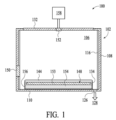
図1は、1つ以上のチャンバ構成要素を有する処理チャンバ100(例えば、半導体処理チャンバ)の断面図であり、このチャンバ構成要素は、1つ以上の相のY2O3-ZrO2から実質的に構成される耐プラズマ性セラミック材料を含み、本開示の諸実施形態によれば、セラミック材料は55~65mol%のY2O3及び35~45mol%のZrO2から実質的に構成される。さらに別の実施形態では、セラミック材料は56~65mol%のY2O3及び35~44mol%のZrO2から実質的に構成される。さらに別の実施形態では、セラミック材料は57~65mol%のY2O3及び35~43mol%のZrO2から実質的に構成される。さらに別の実施形態では、セラミック材料は58~65mol%のY2O3及び35~42mol%のZrO2から実質的に構成される。さらに別の実施形態では、セラミック材料は59~65mol%のY2O3及び35~41mol%のZrO2から実質的に構成される。さらに別の実施形態では、セラミック材料は60~65mol%のY2O3及び35~40mol%のZrO2から実質的に構成される。さらに別の実施形態では、セラミック材料は55~64mol%のY2O3及び36~45mol%のZrO2から実質的に構成される。さらに別の実施形態では、セラミック材料は55~63mol%のY2O3及び37~45mol%のZrO2から実質的に構成される。さらに別の実施形態では、セラミック材料は55~62mol%のY2O3及び38~45mol%のZrO2から実質的に構成される。さらに別の実施形態では、セラミック材料は55~61mol%のY2O3及び39~45mol%のZrO2から実質的に構成される。さらに別の実施形態では、セラミック材料は55~60mol%のY2O3及び40~45mol%のZrO2から実質的に構成される。さらに別の実施形態では、セラミック材料は56~64mol%のY2O3及び36~44mol%のZrO2から実質的に構成される。さらに別の実施形態では、セラミック材料は57-63mol%のY2O3及び37-43mol%のZrO2から実質的に構成される。さらに別の実施形態では、セラミック材料は58-62mol%のY2O3及び36-42mol%のZrO2から実質的に構成される。さらに別の実施形態では、セラミック材料は59-61mol%のY2O3及び39-41mol%のZrO2から実質的に構成される。さらに別の実施形態では、セラミック材料は約60mol%のY2O3及び約40mol%のZrO2から実質的に構成される。Y2O3-ZrO2のセラミック材料から成る焼結セラミック体は約0.1%の気孔率を有する場合がある。ここで、気孔率は気孔体積分率である。 FIG. 1 is a cross-sectional view of a processing chamber 100 (eg, a semiconductor processing chamber) having one or more chamber components that are substantially made of one or more phases of Y 2 O 3 —ZrO 2 . and according to embodiments of the present disclosure, the ceramic material consists essentially of 55-65 mol % Y 2 O 3 and 35-45 mol % ZrO 2 . . In yet another embodiment, the ceramic material consists essentially of 56-65 mol % Y 2 O 3 and 35-44 mol % ZrO 2 . In yet another embodiment, the ceramic material consists essentially of 57-65 mol % Y 2 O 3 and 35-43 mol % ZrO 2 . In yet another embodiment, the ceramic material consists essentially of 58-65 mol % Y 2 O 3 and 35-42 mol % ZrO 2 . In yet another embodiment, the ceramic material consists essentially of 59-65 mol % Y 2 O 3 and 35-41 mol % ZrO 2 . In yet another embodiment, the ceramic material consists essentially of 60-65 mol % Y 2 O 3 and 35-40 mol % ZrO 2 . In yet another embodiment, the ceramic material consists essentially of 55-64 mol % Y 2 O 3 and 36-45 mol % ZrO 2 . In yet another embodiment, the ceramic material consists essentially of 55-63 mol % Y 2 O 3 and 37-45 mol % ZrO 2 . In yet another embodiment, the ceramic material consists essentially of 55-62 mol % Y 2 O 3 and 38-45 mol % ZrO 2 . In yet another embodiment, the ceramic material consists essentially of 55-61 mol % Y 2 O 3 and 39-45 mol % ZrO 2 . In yet another embodiment, the ceramic material consists essentially of 55-60 mol % Y 2 O 3 and 40-45 mol % ZrO 2 . In yet another embodiment, the ceramic material consists essentially of 56-64 mol % Y 2 O 3 and 36-44 mol % ZrO 2 . In yet another embodiment, the ceramic material consists essentially of 57-63 mol % Y 2 O 3 and 37-43 mol % ZrO 2 . In yet another embodiment, the ceramic material consists essentially of 58-62 mol % Y 2 O 3 and 36-42 mol % ZrO 2 . In yet another embodiment, the ceramic material consists essentially of 59-61 mol % Y 2 O 3 and 39-41 mol % ZrO 2 . In yet another embodiment , the ceramic material consists essentially of about 60 mol% Y2O3 and about 40 mol% ZrO2 . A sintered ceramic body of Y 2 O 3 —ZrO 2 ceramic material may have a porosity of about 0.1%. Here, the porosity is the pore volume fraction.
処理チャンバ100は、腐食性プラズマ環境が生じるプロセスに使用することができる。例えば、処理チャンバ100は、プラズマエッチングリアクタ(プラズマエッチャとしても知られる)、プラズマクリーナなどのためのチャンバであってもよい。Y2O3-ZrO2から実質的に構成されるセラミック材料を含み得るか又はそれから形成され得るチャンバ構成要素の例には、蓋132、ノズル152、チャンバドア150、静電チャック(ESC)148のパック153、リング(例えば、プロセスキットリング又はシングルリング)134、ガス分配プレート(図示せず)、ヒータ基板支持体(図示せず)などがある。これらのチャンバ構成要素の各々は、1つ以上の理由により、Y2O3-ZrO2から実質的に構成されるセラミック材料を使用することで恩恵を受ける。例えば、Y2O3-ZrO2のセラミック材料であって、55~60mol%のY2O3及び40~45mol%のZrO2、56~64mol%のY2O3及び36~44mol%のZrO2、57~63mol%のY2O3及び37~43mol%のZrO2、58~62mol%のY2O3及び36~42mol%のZrO2、59~61mol%のY2O3及び39~41mol%のZrO2、又は約60mol%のY2O3及び約40mol%のZrO2を含むセラミック材料は、他のセラミック材料と比較して、硬さ、耐エロージョン性、耐絶縁破壊性、及び/又は引張強度に関する最適な又は最適に近い組み合わせを有し得る(ここでの他のセラミック材料には、65mol%を超えるY2O3及び35mol%未満のZrO2を含むY2O3-ZrO2、並びに55mol%未満のY2O3及び45mol%を超えるZrO2を含むY2O3-ZrO2が含まれる)。
The
以下の表1には、様々な濃度のY2O3とZrO2の混合物を含む様々なバルク焼結セラミック材料の特性が提供されている。この表では、サンプルAは、100mol%のY2O3を含み、サンプルBは、73.2mol%のY2O3及び26.8mol%のZrO2を含み、サンプルCは、64.5mol%のY2O3及び35.5mol%のZrO2を含み、サンプルDは、60.3mol%のY2O3及び39.7mol%のZrO2を含み、サンプルEは、57.7mol%のY2O3及び42.3mol%のZrO2を含む。提示のように、いくつかの用途のための最適な特性が、60.3mol%のY2O3及び39.7mol%のZrO2を用いることで、達成されている。例えば、60.3mol%のY2O3及び39.7mol%のZrO2から実質的に構成されるセラミック材料は、最高の平均曲げ強度、最高のビッカース硬さ、及び最高の破壊靭性を、試験を行った組成物の中で示すと共に、高い弾性率、密度、約500~600V/ミルの耐絶縁破壊性、及び耐プラズマエロージョン性も示す。同様の望ましい特性は、59~61mol%のY2O3及び39~41mol%のZrO2、58~62mol%のY2O3及び36~42mol%のZrO2、57~63mol%のY2O3及び37~43mol%のZrO2等を用いることでも達成されるが、60.3mol%のY2O3及び39.7mol%のZrO2から逸脱するほど、セラミック材料の特性の組合せはこの用途にとって望ましくない状態になる。熱衝撃抵抗係数(R’)は以下の式を用いて計算される。 Table 1 below provides the properties of various bulk sintered ceramic materials containing mixtures of Y2O3 and ZrO2 at various concentrations. In this table , sample A contains 100 mol% Y2O3 , sample B contains 73.2 mol% Y2O3 and 26.8 mol% ZrO2 , sample C contains 64.5 mol% of Y 2 O 3 and 35.5 mol % ZrO 2 , sample D contains 60.3 mol % Y 2 O 3 and 39.7 mol % ZrO 2 , sample E contains 57.7 mol % Y 2 O 3 and 42.3 mol % ZrO 2 . As presented, optimal properties for some applications have been achieved using 60.3 mol % Y 2 O 3 and 39.7 mol % ZrO 2 . For example, a ceramic material consisting essentially of 60.3 mol% Y2O3 and 39.7 mol% ZrO2 has the highest average bending strength, highest Vickers hardness, and highest fracture toughness tested. It also exhibits high modulus, density, dielectric breakdown resistance of about 500-600 V/mil, and plasma erosion resistance. Similar desirable properties are 59-61 mol % Y 2 O 3 and 39-41 mol % ZrO 2 , 58-62 mol % Y 2 O 3 and 36-42 mol % ZrO 2 , 57-63 mol % Y 2 O 3 and 37-43 mol% ZrO2, etc., but the combination of properties of the ceramic material deviates from 60.3 mol% Y2O3 and 39.7 mol% ZrO2 for this application. become undesirable for The thermal shock resistance coefficient (R') is calculated using the following formula.


一実施形態では、処理チャンバ100は、内部容積106を取り囲むチャンバ本体102と蓋132とを含む。蓋132は、蓋132のほぼ中央に貫通孔を備えて、この貫通孔にノズル152を収容してもよい。チャンバ本体102を、アルミニウム、ステンレス鋼、又は他の適切な材料から製造してもよい。チャンバ本体102は、一般に、側壁108と底部110とを備える。
In one embodiment, processing
外側ライナ116を側壁108に隣接して配置し、チャンバ本体102を保護してもよい。外側ライナ116は、Al2O3又はY2O3などの耐ハロゲン含有ガス性材料であってもよい。
An
排気口126がチャンバ本体102内に画定されてもよく、内部容積106をポンプシステム128に接続してもよい。ポンプシステム128は、1つ以上のポンプ及びスロットル弁を備えて使用し、処理チャンバ100の内部容積106の圧力を抜いて調整してもよい。
An
蓋132は、チャンバ本体102の側壁108及び/又はチャンバ本体の上部に支持されてもよい。蓋132によって、処理チャンバ100が封止されてもよい。いくつかの実施形態では、蓋132が解放されて、処理チャンバ100の内部容積106へのアクセスを可能にしてもよい。ガスパネル158を処理チャンバ100に接続して、ノズル152のガス送出孔を介して内部容積106に処理ガス及び/又はクリーニングガスを供給してもよい。処理チャンバ100内で基板を処理するために使用することができる処理ガスの例には、とりわけC2F6、SF6、SiCl4、HBr、NF3、CF4、CHF3、CH2F3、F、Cl2、CCl4、BCl3、SiF4などのハロゲン含有ガス、及びO2などの他のガス又はN2Oがある。キャリアガスの例には、N2、He、Ar、及び処理ガスに対して不活性な他のガス(例えば、非反応性ガス)がある。
The
静電チャック148又はヒータ基板支持体(図示せず)などの基板支持体アセンブリが、蓋132及びノズル152の下の処理チャンバ100の内部容積106に配置されている。静電チャック148は、処理中に基板144(例えば半導体ウェハ)を保持する。静電チャック148は、処理中に基板144をしっかりと固定することができ、熱伝導性(例えば、金属)ベース154(熱伝導性プレートとも呼ばれる)及び/又は1つ以上の更なる構成要素に接合された静電パック153を含むことができる。熱伝導性ベース154は、Alから構成されてもよい。諸実施形態では、熱伝導性ベース154の外壁は、陽極酸化層156(例えば、Al2O3陽極酸化層)を含む。諸実施形態では、プロセスキットリングなどのリング134は、静電パック153の外周で静電チャック上に配置されてもよい。
A substrate support assembly, such as an
チャンバ本体102には、チャンバ本体102の側壁に穴があってもよい。諸実施形態では、穴はチャンバドア150によって覆われてもよい。内部容積106は、処理中及び/又はクリーニング中にプラズマで満たされてもよい。穴は、プラズマを加速するためにチャンバ本体102内に発生させる高周波(RF)場に不均一性を引き起こす可能性がある。この不均一性により、穴においてアーク放電及びプラズマ強度の増加が引き起こされる可能性がある。チャンバドア150は、55~65mol%のY2O3及び35~45mol%のZrO2を有するY2O3-ZrO2から実質的に構成されるセラミック材料から構成されてもよく、このセラミック材料は、内部容積106内のプラズマに対する高い耐性を提供し、また高い耐絶縁破壊性を有する。高い耐絶縁破壊性によって、高周波場におけるあらゆる不均一性は排除又は低減され得て、アーク放電も排除及び/又は抑制され得る。55~65mol%のY2O3及び35~45mol%のZrO2を有するY2O3-ZrO2から実質的に構成されるセラミック材料は、高い曲げ強度を有しており、これにより、チャンバドア150の破損が軽減又は解消される。55~65mol%のY2O3及び35~45mol%のZrO2を有するY2O3-ZrO2から実質的に構成されるセラミック材料は、高い硬さを有しており、これにより、チャンバドア150の摩耗が軽減される。一実施形態では、チャンバドア150は、セラミック体に取り付けられた、金属構成要素を含む湾曲した跳ね上げドアであり、金属構成要素はヒンジ機構を備えている、及び/又はヒンジ機構に取り付けられている。一実施形態では、チャンバドアは約0.5~1.5インチの厚さ、約3~6インチ(例えば約4~5インチ)の第1寸法(例えば長さ)、及び約8~16インチ(例えば約10~14インチ)の第2寸法(例えば高さ)を有する。
The
図2は、静電チャック148の一実施形態の分解図を示す。静電チャック148は、熱伝導性ベース154に接合された静電パック153を含む。静電パック153は、その上に配置される基板144の形状及びサイズとほぼ一致し得る環状周縁部を有する円盤状の形状を有する。静電パック153は、1つ以上の埋め込み加熱素子及び/又は1つ以上の埋め込みチャッキング電極を備えてもよい。いくつかの実施形態では、加熱素子は、支持されている基板を最高約350℃の温度に加熱するように構成されてもよい。静電パック153はさらに、静電パック153の表面上にメサと、1つ以上のガス送出孔とを備えてもよい。それは、静電パックの表面と支持されている基板の裏側との間に熱伝導ガス(例えば、He)を供給することを目的としている。
FIG. 2 shows an exploded view of one embodiment of
一実施形態では、静電パック166は、Y2O3-ZrO2から実質的に構成されるセラミック材料で製造された焼結セラミック体とすることができる。いくつかの実施形態では、静電パック166は、0.04~0.25インチの厚さ及び7.85~12.90インチの直径を有することができる。一実施形態では、静電パック153は、55~65mol%のY2O3及び35~45mol%のZrO2を有するY2O3-ZrO2から実質的に構成されるセラミック材料で形成された第1セラミック体を含み、AlN又はAl2O3から実質的に構成される第2セラミック体に接合されている。55~65mol%のY2O3及び35~45mol%のZrO2(例えば、約60mol%のY2O3及び約40mol%のZrO2)を有するY2O3-ZrO2から実質的に構成されるセラミック材料を使用することで、耐絶縁破壊性、耐プラズマエロージョン性及び硬さの最適な又は最適に近い組み合わせが静電パック153に提供される。耐絶縁破壊性及び抵抗率は、クーロン力型静電チャック及びジョンセン・ラーベック(JR)力型静電チャックの両方にとって静電パック153の有用な特性となり得る。加えて、粒子汚染を最小にし、ESC148の寿命を最長にするために、耐エロージョン性は高くなければならない。さらに、静電パック153は、使用中に多くの基板と物理的に接触するが、このことが静電パック153の摩耗を引き起こす。9.4GPaという高い硬さによって、基板又はウェハの処理中の(例えば、支持されている基板と静電パック153との間の熱膨張係数の不一致のために生じる相対運動による)摩耗に耐える。約55~65mol%のY2O3及び約35~45mol%のZrO2を有するY2O3-ZrO2から実質的に構成されるセラミック材料の高い硬さのおかげで、そのような摩耗は最小になる。
In one embodiment, electrostatic puck 166 may be a sintered ceramic body made from a ceramic material consisting essentially of Y 2 O 3 —ZrO 2 . In some embodiments, the electrostatic puck 166 can have a thickness of 0.04-0.25 inches and a diameter of 7.85-12.90 inches. In one embodiment, the
静電パック153の下に取り付けられた熱伝導性ベース154は、円盤状の本体を有し得る。いくつかの実施形態では、熱伝導性ベース154は、上に重なる静電パック153の熱特性と実質的に一致する熱特性を有する材料によって製造されてもよい。一実施形態では、熱伝導性ベース154は、アルミニウム、ステンレス鋼、又は他の適切な材料などの金属によって製造されてもよい。あるいは、熱伝導性ベース154は、良好な強度及び耐久性と共に良好な熱伝達特性を提供する、セラミックと金属材料との複合材料によって製造されてもよい。複合材料は、上に重なる静電パック153と実質的に一致する熱膨張係数を有して、いくつかの実施形態で熱膨張の不一致を軽減してもよい。
A thermally
諸実施形態では、熱伝導性ベース154は、シリコーンボンドで静電パック153に接着されてもよい。いくつかの実施形態では、静電パック153は、AlN又はAl2O3の第1セラミック体から形成される。AlNをジョンソン・ラーベック力型静電チャックに使用し、Al2O3をクーロン力型静電チャックに使用してもよい。第1セラミック体は、その中に埋め込まれた1つ以上のチャッキング電極及び/又は1つ以上の加熱電極を備えてもよい。約55~65mol%のY2O3及び約35~45mol%のZrO2を有するY2O3-ZrO2から形成された第2セラミック体(例えば、薄いウェハ)を、拡散接合によって第1セラミック体に接合してもよい。拡散接合は、約120~130℃の温度及び最高約300ポンド毎平方インチ(PSI)の圧力を使用して実行されてもよい。
In embodiments, thermally
(AlN又はAl2O3の)第1セラミック体と(約55~65mol%のY2O3及び約35~45mol%のZrO2を有するY2O3-ZrO2から形成された)第2セラミック体の間の拡散接合では、第1セラミック体と第2セラミック体との間に界面層が形成されるであろう。この界面層は、Y、Zr、Al及びOから構成されてもよい。 a first ceramic body (of AlN or Al 2 O 3 ) and a second (formed from Y 2 O 3 -ZrO 2 with about 55-65 mol % Y 2 O 3 and about 35-45 mol % ZrO 2 ); Diffusion bonding between ceramic bodies will form an interfacial layer between the first and second ceramic bodies. This interfacial layer may consist of Y, Zr, Al and O.
図3A及び図3Bには、諸実施形態によるヒータアセンブリ305が示されている。いくつかの実施形態では、ヒータアセンブリ305は、ESC148に対する代替の基板支持体アセンブリとして使用されてもよい。ヒータアセンブリ305は、1つ以上の埋め込まれた加熱素子(図示せず)を有する平坦なセラミックヒータプレート310を備える。いくつかの実施形態では、セラミックヒータプレート310は、0.3~0.9インチの厚さ及び7.9~14.8インチの直径を有してもよい。諸実施形態では、セラミックヒータプレート310は、セラミックヒータプレート310の上面に1つ以上のメサを含んでもよい。セラミックヒータプレート310は、処理中に基板を支持することができ、基板を最高約650℃の温度まで加熱するように構成されてもよい。
A
セラミックヒータプレート310は、漏斗形状体320に接合されてもよく、この漏斗形状体320では、漏斗形状体320の底部よりも漏斗形状体320の上部において内径及び外径は大きくなっている。諸実施形態では、セラミックヒータプレート310と漏斗形状体320との間の接合は、1000℃を超える温度(例えば、最高1800℃)及び最高約800PSI(例えば、300~800PSI)の圧力での拡散接合で行われてもよい。諸実施形態では、漏斗形状体320はAlNから構成されてもよく、中空として、セラミックヒータプレート310と、セラミックヒータプレート310を収容するチャンバの他の構成要素との間の熱伝達を最小限に抑えてもよい。AlN製漏斗形状体320に、1つ以上のドーパントを加えて、熱伝導率を調整してもよい。そのようなドーパントの例には、サマリウム、イットリウム及びマグネシウムがある。
The
セラミックヒータプレート310と漏斗形状体320との間の拡散接合のために、セラミックヒータプレート310と漏斗形状体との間に界面層が形成されてもよい。この界面層は、Y、Zr、Al及びOから構成されてもよい。
An interface layer may be formed between the
いくつかの実施形態では、セラミックヒータプレート310は更なるセラミックヒータプレート315に連結されている。更なるセラミックヒータプレート315は、AlNから構成されてもよい。いくつかの実施形態では、セラミックヒータプレート310は加熱素子を備えず、代わりに更なるセラミックヒータプレート315が加熱素子を備える。セラミックヒータプレート310は、例えば拡散接合又はボルトによって更なるセラミックヒータプレート315に連結されてもよい。
In some embodiments,
諸実施形態では、この拡散接合は、1000℃を超える温度(例えば、最高1800℃)及び最高約800PSI(例えば、300~800PSI)の圧力での拡散接合で行われてもよい。更なるセラミックヒータプレート315は、漏斗形状体320に接合されてもよく、この漏斗形状体320では、漏斗形状体320の底部よりも漏斗形状体320の上部において内径及び外径は大きくなっている。諸実施形態では、更なるセラミックヒータプレート315と漏斗形状体320との間の接合は、1000℃を超える温度(例えば、最高1800℃)及び最高約800PSI(例えば、300~800PSI)の圧力での拡散接合で行われてもよい。セラミックヒータプレート310と更なるセラミックヒータプレート315との間の拡散接合のために、セラミックヒータプレート310と更なるセラミックヒータプレート315との間に界面層が形成されてもよい。界面層は、Y、Zr、Al及びOから構成されてもよい。
In embodiments, this diffusion bonding may be done with diffusion bonding at temperatures above 1000° C. (eg, up to 1800° C.) and pressures up to about 800 PSI (eg, 300-800 PSI). A further
セラミックヒータ310は、(例えば、最高約650℃までの)高温でフッ素系のプラズマに曝される場合がある。フッ素がセラミックヒータ310の表面上に形成され、セラミックヒータ310内のAlのような、いかなる微量金属とも反応(例えば、AlF3を形成)することがある。AlF3は蒸気圧が低いため、約650℃までの温度で気化又は昇華する可能性がある。その場合、AlF3はチャンバ内の他のチャンバ構成要素上で凝縮し、処理済み基板の粒子汚染を招く可能性がある。したがって、諸実施形態では、非常に純度が高く、Alや微量金属を欠くY2O3-ZrO2のセラミック材料が使用されて、チャンバ構成要素へのフッ化物の蓄積を防ぐ。セラミックヒータ310は(静電チャック148と同様に)基板を支持するので、55~65mol%のY2O3及び35~45mol%のZrO2を有するY2O3-ZrO2という、セラミック材料のための組成は最適であるか、最適に近く、それは、最高の硬さ、最高の曲げ強度、最高の破壊靭性、及び高い耐プラズマエロージョン性が提供されるからである。
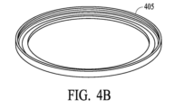
図4A及び図4Bは、諸実施形態によるプロセスキットリング405の上面図及び底面図をそれぞれ示す。プロセスキットリング405は、諸実施形態でのリング134に相当し得る。諸実施形態では、プロセスキットリング405は、約0.5~1.5インチの厚さと、約11~15インチ(例えば、約11.8~14インチ)の内径(ID)寸法と、約12~16インチの外径(OD)寸法を有し得る。諸実施形態では、プロセスキットリング405の上部の外縁は丸みを帯びていてもよい。諸実施形態では、リングの幅(IDとODとの間の差)は、約1~2.5インチであってもよい。プロセスキットリング405は、支持されている基板と接触することがあり、したがって、そのような接触によって摩耗する可能性がある。さらに、プロセスキットリング405は、比較的大きな直径を有し、比較的薄く、比較的狭い幅を有する。これらの要因により、取扱中及び/又は使用中にプロセスキットリング405が破損する可能性がある。さらに、プロセスキットリング405は、処理中にプラズマに曝されることがある。したがって、プロセスキットリング405は、耐プラズマ性、硬さ、曲げ強度及び破壊靭性の組み合わせでの、55~65mol%のY2O3及び35~45mol%のZrO2を有するY2O3-ZrO2のセラミック材料が示す利点から恩恵を受ける(このセラミック材料は、例えば、約60mol%のY2O3及び約40mol%のZrO2を含むY2O3-ZrO2のセラミック材料である)。
4A and 4B show top and bottom views, respectively, of a
図5A及び図5Bは、諸実施形態による、処理チャンバ用の蓋505の上面図及び底面図をそれぞれ示す。蓋505は、諸実施形態での蓋132に相当し得る。諸実施形態において、蓋505は、約1~2インチの厚さと、約19~23インチの直径を有し得る。蓋505は、異なる熱膨張係数を有し得る他のチャンバ構成要素と接触し、そのような接触によって摩耗する場合がある。さらに、蓋505は比較的大きな直径を有し、比較的薄くできている。これらの要因により、取扱中及び/又は使用中に蓋505が破損する可能性がある。さらに、蓋505は処理中にプラズマに曝されることがある。したがって、蓋505は、耐プラズマ性、硬さ、曲げ強度及び破壊靭性の組み合わせでの、55~65mol%のY2O3及び35~45mol%のZrO2を有するY2O3-ZrO2のセラミック材料が示す利点から恩恵を受ける(このセラミック材料は、例えば、約60mol%のY2O3及び約40mol%のZrO2を含むY2O3-ZrO2のセラミック材料である)。
5A and 5B show top and bottom views, respectively, of a
図6A及び図6Bは、諸実施形態による、処理チャンバ用のノズル605の上面図及び底面図をそれぞれ示す。ノズル605は、諸実施形態でのノズル152に相当し得る。ノズル605は複数のガス送出孔を備えてもよい。ノズル605は、蓋505の中心又はその付近の穴に嵌合してもよい。
Figures 6A and 6B show top and bottom views, respectively, of a
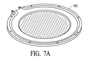
いくつかの実施形態では、チャンバは、蓋及びノズルではなく、ガス送出プレート(GDP)を備え得る。図7A及び図7Bは、諸実施形態による、処理チャンバ用のGDP705の上面図及び底面図をそれぞれ示す。GDP705は、多数(例えば、数千)のガス送出孔を備え得る。諸実施形態では、GDP705は、約1mm(例えば、0.04)から約1インチの厚さと、約18~22インチの直径を有し得る。一実施形態では、GDP705は約1~6mmの厚さを有する。GDP705は、耐荷重性構成要素であってもよく、比較的大きい直径を有し、比較的薄くてもよい。これらの要因により、取扱中及び/又は使用中にGDP705が破損する場合がある。さらに、GDP705は処理中にプラズマに曝されることがある。したがって、GDP705は、耐プラズマ性、硬さ、曲げ強度及び破壊靭性の組み合わせでの、55~65mol%のY2O3及び35~45mol%のZrO2を有するY2O3-ZrO2のセラミック材料が示す利点から恩恵を受ける(このセラミック材料は、例えば、約60mol%のY2O3及び約40mol%のZrO2を含むY2O3-ZrO2のセラミック材料である)。55~65mol%のY2O3及び35~45mol%のZrO2を有するY2O3-ZrO2のセラミック材料(このセラミック材料は、例えば、約60mol%のY2O3及び約40mol%のZrO2を含むY2O3-ZrO2のセラミック材料である)の有益な耐絶縁破壊性によって、GDP705に使用された時には、アーク放電も低減され得る。いくつかの実施形態では、GDP705は、更なる機械的強度のためにバッキングプレート(例えば、Al製バッキングプレートなどの金属バッキングプレート)に結合される。GDP705は、バッキングプレートに機械的に固定されてもよく、又はバッキングプレートに(例えば、拡散接合によって)接合されてもよい。
In some embodiments, the chamber may include a gas delivery plate (GDP) rather than a lid and nozzle. 7A and 7B show top and bottom views, respectively, of
図8は、本開示の一実施形態による、固体焼結セラミック物品を製造するための方法800を示すフローチャートである。ブロック855では、セラミック物品を形成するために使用されることになるY2O3及びZrO2のセラミック粉末が選択される。選択されたセラミック粉末の量もまた選択される。諸実施形態では、Y2O3のセラミック粉末は少なくとも99.99%の純度を有し、ZrO2のセラミック粉末は少なくとも99.8%の純度を有してもよい。
FIG. 8 is a flowchart illustrating a
ブロック858で、選択された粉末に対して精製プロセスを実行してもよい。
At
ブロック860で、選択されたセラミック粉末が混合される。一実施形態では、選択されたセラミック粉末を水、バインダ及び解膠剤と混合してスラリーを形成する。一実施形態では、セラミック粉末は、ボールミル粉砕などの粉砕プロセスを使用して混合される。混合では、セラミック粒子を、目標粒径及び目標粒径分布を有する凝集物へと凝集させてもよい。特に、諸実施形態では、セラミック粉末の混合物は更なる焼結助剤をいっさい含まない。一実施形態では、セラミック粉末は、噴霧乾燥によって粒状粉末と組み合わされる。噴霧乾燥プロセスでは、凝集物中の液体又は溶媒が揮発し得る。
At
ブロック865では、グリーン体(未焼結セラミック物品)が混合粉末から(例えば、選択されたセラミック粉末の混合物から形成されたスラリーから)形成される。グリーン体は、スリップキャスティング、テープキャスティング、冷間等方圧加圧法、一方向性機械プレス成形、射出成形、及び押出し成形を含む技術を用いて形成することができるが、これらの技術に限定されない。例えば、一実施形態では、スラリーを噴霧乾燥し、型に入れ、プレスして、グリーン体を形成することができる。一実施形態では、グリーン体は冷間等方圧加圧法によって形成される。グリーン体は、製造するチャンバ構成要素のおおよその形状を有してもよい。
At
一実施形態では、ブロック866において、グリーン体に対してグリーン加工を施してもよい。グリーン加工には、例えばグリーン体への穿孔が含まれてもよい。
In one embodiment, at
ブロック868では、グリーン体に第1熱処理が行われて、グリーン体中の有機バインダを熱して除く。一実施形態では、第1熱処理は、グリーン体を約1~2週間の期間にわたって約950℃の高温に曝すことによって行われる。
At
ブロック870では、グリーン体に対して第2熱処理が行われ、グリーン体を焼結して、55~65mol%のY2O3及び35~45mol%のZrO2から実質的に構成される(例えば、約60mol%のY2O3及び約40mol%のZrO2から実質的に構成される)焼結セラミック体を製造する。グリーン体を焼結することには、グリーン体を、Y2O3及びZrO2の融点より低い高温にまで加熱することが含まれてもよい。諸実施形態では、第2熱処理プロセスは、約1750~1900℃の温度で約3~30時間にわたって実行されてもよい。諸実施形態では、焼結は、空気、酸素及び/又は水素の存在下で(例えば、グリーン体を加熱している炉にこれらのガスのいずれかを流すことによって)実行されてもよい。焼結プロセスでは、グリーン体が緻密化されて、約0.1の気孔率を有する固体焼結セラミック物品が製造され、この固体焼結セラミック物品は、少なくとも1つのY2O3-ZrO2相(例えば、Y2O3-ZrO2固溶体)を含む。諸実施形態では、焼結プロセスは、常圧焼結プロセスであってもよい。
At
様々な実施形態では、固体焼結セラミック物品は、プラズマエッチングリアクタ又は他のチャンバの別のチャンバ構成要素に使用されてもよい。製造される特定のチャンバ構成要素に応じて、グリーン体は異なる形状を有してもよい。例えば、最終的なチャンバ構成要素がプロセスキットリングになる場合、グリーン体はリング形状であってもよい。チャンバ構成要素が静電チャックのための静電パックになる場合、グリーン体は円盤形状であってもよい。グリーン体はまた、製造されるチャンバ構成要素に応じて他の形状を有してもよい。 In various embodiments, solid sintered ceramic articles may be used in another chamber component of a plasma etch reactor or other chamber. Depending on the particular chamber component being manufactured, the green body may have different shapes. For example, the green body may be ring shaped if the final chamber component will be a process kit ring. If the chamber component becomes an electrostatic pack for an electrostatic chuck, the green body may be disc-shaped. The green body may also have other shapes depending on the chamber component being manufactured.
焼結プロセスによって、通常は、制御できない量だけセラミック物品のサイズが変化する。少なくともいくらかはこのサイズの変化に起因して、セラミック物品は通常、焼結プロセスが完了した後にブロック875で機械加工が施される。機械加工には、セラミック物品の表面研削及び/又は研磨、セラミック物品への穿孔、セラミック物品への切削及び/又は成形、セラミック物品の研削、セラミック物品の研摩(例えば、化学的機械的平坦化(CMP)、火炎研磨、又は他の研磨技術を用いた研磨)、セラミック物品の粗面化(例えば、ビードブラスト処理による粗面化)、セラミック物品上へのメサの形成などが含まれてもよい。
The sintering process usually changes the size of the ceramic article by an uncontrollable amount. Due at least in part to this size variation, ceramic articles are typically machined at
焼結後、焼結セラミック体に色の不均一性が生じることがある。色の不均一性は、焼結セラミック体から形成されたチャンバ構成要素が顧客から返却される原因となる欠陥になり得る。したがって、一実施形態では、ブロック880で、焼結セラミック体に第3熱処理を施して、焼結セラミック体の色を均質化する。諸実施形態では、焼結セラミック体は、第3熱処理後に均一な白色を有する。第3熱処理は、約1000~1400℃の温度で2~12時間にわたって実施してもよい。
After sintering, color non-uniformity may occur in the sintered ceramic body. Color non-uniformity can be a defect that causes customer returns of chamber components formed from sintered ceramic bodies. Accordingly, in one embodiment, at
一実施形態では、ブロック866及び/又は875の機械加工プロセスは、荒加工プロセスであり、これにより、焼結セラミック体はおおよその目標形状及び特徴を有することになる。一実施形態では、ブロック885で、更なる機械加工プロセスによって固体焼結セラミック体に再度、機械加工を施す。更なる機械加工プロセスは、微細加工プロセスであってもよく、これにより、焼結セラミック体は目標の形状、粗さ及び/又は特徴を有する。セラミック物品は、特定の用途に適した形状へ機械加工され得る。機械加工の前に、セラミック物品は、特定の目的に適したおおよその形状及びサイズを有してもよい(特定の目的とは、例えば、プラズマエッチャの蓋として使用することである)。しかしながら、機械加工は、チャンバ構成要素のサイズ、形状、寸法、穴のサイズなどを正確に調整するために実行されてもよい。
In one embodiment, the machining process of
ブロック866、875及び/又は885の機械加工プロセスにより、微量金属不純物が焼結セラミック物品に持ち込まれる場合がある。さらに、焼結セラミック物品は、最初のセラミック粉末及び/又は他の製造工程から持ち込まれた非常に少量の微量金属不純物を含み得る。フッ素系のプラズマに曝されることになるチャンバ構成要素の場合、ごく少量の金属不純物でさえも、処理された基板に有害であり得る。したがって、ブロック890において、最終の精製プロセスが焼結セラミック体に対して行われてもよい。精製後には、金属汚染物質は除去され、セラミック体中に100ppm以上の値の金属汚染物質が存在しないようにしてもよい。したがって、精製プロセス後のセラミック体の全体の純度は99.9%になり得る。一実施形態では、最終精製プロセスには湿式クリーニングプロセス及び/又は乾式クリーニングプロセスが含まれる。諸実施形態では、最終精製プロセスでは、焼結セラミック体の表面から微量金属汚染物質を除去することができる。他の実施形態では、最終精製プロセスでは、セラミック体の内部からも、セラミック体の表面と同様に微量金属汚染物質を除去することができる。
The machining processes of
以下の表2では、方法800に従って製造されたセラミック体の金属不純物が示されている。金属不純物は、GDMS分析によって測定され、重量百万分率(wtppm)で表示される。

製造される特定のチャンバ構成要素に応じて、更なる加工作業が追加で行われてもよい。一実施形態では、更なる加工作業は、固体焼結セラミック体を金属体又は他の本体に接合する工程を含む(ブロック895)。場合によっては、ここで固体焼結セラミック体に機械加工と金属体への接合の両方が施される。機械加工が最初に行われ、続いて接合が行われてもよい。他の例では、固体焼結セラミック物品を最初に金属体に接合し、次いで機械加工を施してもよい。他の実施形態では、いくつかの機械加工が接合の前後両方で施される。さらに、いくつかの実施形態では、固体焼結セラミック物品は他のセラミック物品に接合されてもよい。 Further processing operations may additionally be performed depending on the specific chamber components to be manufactured. In one embodiment, further processing operations include joining the solid sintered ceramic body to a metal or other body (block 895). In some cases, the solid sintered ceramic body is now both machined and bonded to a metal body. Machining may occur first, followed by bonding. In another example, a solid sintered ceramic article may first be bonded to a metal body and then machined. In other embodiments, some machining is applied both before and after joining. Further, in some embodiments, solid sintered ceramic articles may be joined to other ceramic articles.
第1例では、セラミック物品はシャワーヘッド又はGDPに使用される。そのような実施形態では、セラミック物品に多くの穴を開けてもよく、セラミック物品をアルミニウム製ガス分配プレートに接合してもよい。第2例では、セラミック物品は静電チャックに使用される。そのような実施形態では、ヘリウムピンホールをセラミック物品に(例えば、レーザー穴開け加工によって)穿孔し、セラミック物品を、シリコーン接着剤又は拡散接合によってアルミニウム製ベースプレートに接合してもよい。他の例では、セラミック物品はセラミック製蓋である。セラミック製蓋は表面積が大きいので、新しい焼結セラミック材料から形成されたセラミック製蓋は、高い構造強度を有して、処理中(例えば、プラズマエッチングリアクタの処理チャンバが真空に引かれたとき)の割れ又は座屈を防ぐことができる。他の諸例では、ノズル、プロセスキットリング、又は他のチャンバ構成要素が形成される。 In a first example, ceramic articles are used in showerheads or GDP. In such embodiments, the ceramic article may be perforated and the ceramic article may be bonded to an aluminum gas distribution plate. In a second example, the ceramic article is used in an electrostatic chuck. In such embodiments, helium pinholes may be drilled into the ceramic article (eg, by laser drilling) and the ceramic article may be bonded to the aluminum baseplate by silicone adhesive or diffusion bonding. In another example, the ceramic article is a ceramic lid. Because of the large surface area of ceramic lids, ceramic lids formed from new sintered ceramic materials have high structural strength to withstand processing during processing (e.g., when the processing chamber of a plasma etch reactor is evacuated). cracking or buckling can be prevented. In other examples, nozzles, process kit rings, or other chamber components are formed.
上記の説明は、特定のシステム、構成要素、方法等の例などを数多く、具体的かつ詳細に説明しており、それは、本開示のいくつかの実施形態を良く理解してもらうことを目的としている。しかしながら、本開示の少なくともいくつかの実施形態は、こうした具体的かつ詳細な説明がなくても実施され得ることが当業者には明らかであろう。他の諸例では、本開示を不必要に不明瞭にすることを避けるために、周知の構成要素又は方法は詳細に説明されないか、又は単純なブロック図形式で提示される。したがって、具体的かつ詳細な説明は単なる例示である。特定の実施態様はこれらの例示的な説明とは異なる場合があるが、なお本開示の範囲内にあると考えられる。 The foregoing description contains numerous specifics and details, such as examples of particular systems, components, methods, etc., for the purpose of providing a thorough understanding of some embodiments of the present disclosure. there is However, it will be apparent to those skilled in the art that at least some embodiments of the present disclosure may be practiced without such specific details. In other instances, well-known components or methods are not described in detail, or are presented in simple block diagram form, in order to avoid unnecessarily obscuring the present disclosure. Accordingly, the specific and detailed descriptions are merely exemplary. Particular implementations may differ from these exemplary descriptions and still be considered within the scope of the present disclosure.
本明細書全体を通して「ある実施形態」又は「一実施形態」と言及した場合、その実施形態に関連して説明した特定の構成、構造、又は特性は少なくとも1つの実施形態に含まれることを意味する。したがって、本明細書全体を通じて様々な箇所に「ある実施形態では」又は「一実施形態では」という表現が出現しても、必ずしもすべてが同じ実施形態を指すものではない。さらに、用語「又は」は、排他的な「又は」ではなく、包括的な「又は」を意味することを意図している。 References to "an embodiment" or "an embodiment" throughout this specification are meant to include in at least one embodiment the particular configuration, structure, or feature described in connection with that embodiment. do. Thus, the appearances of the phrases "in one embodiment" or "in one embodiment" in various places throughout this specification are not necessarily all referring to the same embodiment. Moreover, the term "or" is intended to mean an inclusive "or" rather than an exclusive "or."
本明細書における方法の動作は特定の順序で示され説明されているが、各方法の動作の順序を変更して、ある動作が逆の順序で実行されるか、又は、ある動作が他の動作と少なくとも部分的に並行して実行されてもよい。別の実施形態では、異なる動作の指示又は副動作は、断続的に及び/又は交互に行われてもよい。 Although method acts are shown and described herein in a particular order, the order of the method acts may be changed so that some acts are performed in the reverse order or some acts are performed in the other order. Operations may be performed at least partially in parallel. In other embodiments, different motion instructions or sub-motions may occur intermittently and/or alternately.
上記の説明は例示的であり、限定的ではないことを意図していると理解すべきである。上記の説明を読み理解することにより、他の多くの実施形態が当業者にとって明らかとなる。したがって、本開示の範囲は、添付の特許請求の範囲を参照して、そのような特許請求の範囲が権利を有する均等物の全範囲と共に決定されるべきである。 It should be understood that the above description is intended to be illustrative and not restrictive. Many other embodiments will be apparent to those of skill in the art upon reading and understanding the above description. The scope of the present disclosure should, therefore, be determined with reference to the appended claims, along with the full scope of equivalents to which such claims are entitled.
Claims (17)
チャンバ構成要素は、セラミック体の下面に接合された熱伝導性ベースをさらに備え、熱伝導性ベースはAlから実質的に構成され、熱伝導性ベースの側壁は、Al2O3の陽極酸化層を備える、請求項1に記載のチャンバ構成要素。 the chamber component is an electrostatic chuck, the ceramic body is a puck for the electrostatic chuck, and
The chamber component further comprises a thermally conductive base bonded to the lower surface of the ceramic body, the thermally conductive base being substantially composed of Al and sidewalls of the thermally conductive base being an anodized layer of Al2O3 . The chamber component of claim 1, comprising:
チャンバ構成要素は、平坦なセラミックヒータプレートに接合された漏斗形状の軸をさらに備える、請求項1に記載のチャンバ構成要素。 the chamber component is a heater configured to support and heat the wafer, the ceramic body is a flat ceramic heater plate, and
3. The chamber component of claim 1, wherein the chamber component further comprises a funnel-shaped shaft joined to the flat ceramic heater plate.
1つ以上の相のY2O3-ZrO2から実質的に構成される焼結セラミック材料から成るセラミック体であるパックであって、焼結セラミック材料は、55~65mol%のY2O3及び35~45mol%のZrO2から実質的に構成され、焼結セラミック材料は99.9%以上の純度を有し、焼結セラミック材料は、500~600V/ミルの耐絶縁破壊性又は139.4~150MPaの平均曲げ強度を有するパックと、
パックの下面に接合された熱伝導性ベースであって、Alから実質的に構成され、側壁にAl2O3の陽極酸化層を備える熱伝導性ベースを備える静電チャック。 An electrostatic chuck for a processing chamber, comprising:
A puck that is a ceramic body consisting of a sintered ceramic material consisting essentially of one or more phases of Y 2 O 3 —ZrO 2 , the sintered ceramic material comprising 55-65 mol % Y 2 O 3 . and 35-45 mol % ZrO 2 , the sintered ceramic material has a purity of 99.9% or greater, and the sintered ceramic material has a dielectric breakdown resistance of 500-600 V/mil or 139.0 V/mil. a pack having an average bending strength of 4 to 150 MPa ;
An electrostatic chuck comprising a thermally conductive base bonded to the underside of the puck, the thermally conductive base consisting essentially of Al and having an anodized layer of Al2O3 on the sidewalls.
9.4~9.6の熱膨張係数を有する、請求項13に記載の静電チャック。 14. The electrostatic chuck of claim 13 , wherein the sintered ceramic material has a Vickers hardness of 9.1-9.4 GPa or a coefficient of thermal expansion of 9.4-9.6.
b)焼結セラミック材料が58~62mol%のY2O3及び38~42mol%のZrO2から実質的に構成されている、請求項13に記載の静電チャック。 a) the sintered ceramic material consists essentially of 57-63 mol % Y 2 O 3 and 37-43 mol % ZrO 2 , or b) the sintered ceramic material is 58-62 mol % Y 2 O 3 and 38-42 mol % ZrO 2 .
1つ以上の相のY2O3-ZrO2から実質的に構成される焼結セラミック材料から成るセラミック体である平坦なセラミックヒータプレートであって、焼結セラミック材料は、55~65mol%のY2O3及び35~45mol%のZrO2から実質的に構成され、焼結セラミック材料は99.9%以上の純度を有し、焼結セラミック材料は、500~600V/ミルの耐絶縁破壊性又は139.4~150MPaの平均曲げ強度を有するセラミックヒータプレートと、
平坦なセラミックヒータプレートに接合された漏斗形状の軸を備えるヒータ。 A process chamber heater configured to support and heat a wafer, comprising:
A flat ceramic heater plate that is a ceramic body consisting of a sintered ceramic material consisting essentially of one or more phases of Y 2 O 3 —ZrO 2 , the sintered ceramic material comprising 55-65 mol % Consisting essentially of Y 2 O 3 and 35-45 mol % ZrO 2 , the sintered ceramic material has a purity greater than or equal to 99.9%, and the sintered ceramic material has a dielectric breakdown resistance of 500-600 V/mil a ceramic heater plate having an average bending strength of 139.4 to 150 MPa ;
A heater with a funnel-shaped shaft bonded to a flat ceramic heater plate.
9.4~9.6の熱膨張係数を有する、請求項16に記載のヒータ。 17. The heater of claim 16 , wherein the sintered ceramic material has a Vickers hardness of 9.1-9.4 GPa or a coefficient of thermal expansion of 9.4-9.6.
Priority Applications (1)
| Application Number | Priority Date | Filing Date | Title |
|---|---|---|---|
| JP2023092894A JP2023116597A (en) | 2018-03-07 | 2023-06-06 | Y2O3-ZrO2 EROSION RESISTANT MATERIAL FOR CHAMBER COMPONENT IN PLASMA ENVIRONMENT |
Applications Claiming Priority (4)
| Application Number | Priority Date | Filing Date | Title |
|---|---|---|---|
| US201862639941P | 2018-03-07 | 2018-03-07 | |
| US62/639,941 | 2018-03-07 | ||
| US16/279,247 | 2019-02-19 | ||
| US16/279,247 US11014853B2 (en) | 2018-03-07 | 2019-02-19 | Y2O3—ZrO2 erosion resistant material for chamber components in plasma environments |
Related Child Applications (1)
| Application Number | Title | Priority Date | Filing Date |
|---|---|---|---|
| JP2023092894A Division JP2023116597A (en) | 2018-03-07 | 2023-06-06 | Y2O3-ZrO2 EROSION RESISTANT MATERIAL FOR CHAMBER COMPONENT IN PLASMA ENVIRONMENT |
Publications (3)
| Publication Number | Publication Date |
|---|---|
| JP2019194351A JP2019194351A (en) | 2019-11-07 |
| JP2019194351A5 JP2019194351A5 (en) | 2022-04-01 |
| JP7292060B2 true JP7292060B2 (en) | 2023-06-16 |
Family
ID=67843180
Family Applications (2)
| Application Number | Title | Priority Date | Filing Date |
|---|---|---|---|
| JP2019042015A Active JP7292060B2 (en) | 2018-03-07 | 2019-03-07 | Y2O3-ZrO2 Erosion Resistant Materials for Chamber Components in Plasma Environments |
| JP2023092894A Pending JP2023116597A (en) | 2018-03-07 | 2023-06-06 | Y2O3-ZrO2 EROSION RESISTANT MATERIAL FOR CHAMBER COMPONENT IN PLASMA ENVIRONMENT |
Family Applications After (1)
| Application Number | Title | Priority Date | Filing Date |
|---|---|---|---|
| JP2023092894A Pending JP2023116597A (en) | 2018-03-07 | 2023-06-06 | Y2O3-ZrO2 EROSION RESISTANT MATERIAL FOR CHAMBER COMPONENT IN PLASMA ENVIRONMENT |
Country Status (5)
| Country | Link |
|---|---|
| US (2) | US11014853B2 (en) |
| JP (2) | JP7292060B2 (en) |
| KR (2) | KR102422725B1 (en) |
| CN (1) | CN110240481A (en) |
| TW (1) | TWI785212B (en) |
Families Citing this family (16)
| Publication number | Priority date | Publication date | Assignee | Title |
|---|---|---|---|---|
| US11229968B2 (en) * | 2011-11-30 | 2022-01-25 | Watlow Electric Manufacturing Company | Semiconductor substrate support with multiple electrodes and method for making same |
| US11289355B2 (en) | 2017-06-02 | 2022-03-29 | Lam Research Corporation | Electrostatic chuck for use in semiconductor processing |
| KR102655866B1 (en) | 2018-01-31 | 2024-04-05 | 램 리써치 코포레이션 | Electrostatic chuck (ESC) pedestal voltage isolation |
| US11014853B2 (en) | 2018-03-07 | 2021-05-25 | Applied Materials, Inc. | Y2O3—ZrO2 erosion resistant material for chamber components in plasma environments |
| US11086233B2 (en) * | 2018-03-20 | 2021-08-10 | Lam Research Corporation | Protective coating for electrostatic chucks |
| US11309203B2 (en) * | 2018-11-13 | 2022-04-19 | Samsung Electronics Co., Ltd. | Wafer stage and method of manufacturing the same |
| DE102019101657A1 (en) * | 2019-01-23 | 2020-07-23 | Berliner Glas Kgaa Herbert Kubatz Gmbh & Co | Holding device for electrostatically holding a component with a base body joined by diffusion bonding and method for its production |
| USD884855S1 (en) * | 2019-10-30 | 2020-05-19 | Applied Materials, Inc. | Heater pedestal |
| WO2021091695A1 (en) * | 2019-11-05 | 2021-05-14 | Lam Research Corporation | Single crystal metal oxide plasma chamber component |
| CN111620692B (en) * | 2020-04-15 | 2022-06-07 | 深圳市商德先进陶瓷股份有限公司 | Plasma etching resistant ceramic, preparation method thereof and plasma etching equipment |
| US11584993B2 (en) | 2020-10-19 | 2023-02-21 | Applied Materials, Inc. | Thermally uniform deposition station |
| WO2022137467A1 (en) * | 2020-12-24 | 2022-06-30 | トーカロ株式会社 | Electrostatic chuck and processor |
| CN115527825A (en) * | 2021-06-25 | 2022-12-27 | 中微半导体设备(上海)股份有限公司 | Detection device for plasma processing equipment and plasma processing equipment |
| US20230215702A1 (en) * | 2021-12-30 | 2023-07-06 | Applied Materials, Inc. | Uniformity control for plasma processing using wall recombination |
| CN115261800A (en) * | 2022-08-26 | 2022-11-01 | 京东方科技集团股份有限公司 | Evaporation source device and evaporation equipment |
| US20240266200A1 (en) * | 2023-02-08 | 2024-08-08 | Applied Materials, Inc. | Electrostatic Chuck |
Citations (8)
| Publication number | Priority date | Publication date | Assignee | Title |
|---|---|---|---|---|
| JP2001102436A (en) | 1999-05-07 | 2001-04-13 | Applied Materials Inc | Electrostatic chuck and its manufacturing method |
| JP2008239385A (en) | 2007-03-27 | 2008-10-09 | Ngk Insulators Ltd | Composite material and its manufacturing method |
| JP2011011929A (en) | 2009-06-30 | 2011-01-20 | Taiheiyo Cement Corp | Ceramic porous sintered compact, component for semiconductor manufacturing apparatus and shower plate, and method of producing porous sintered compact |
| JP2012116749A (en) | 2007-04-27 | 2012-06-21 | Applied Materials Inc | Apparatus and method for reducing erosion rate of surface exposed to halogen-containing plasma |
| WO2015137270A1 (en) | 2014-03-10 | 2015-09-17 | 住友大阪セメント株式会社 | Dielectric material and electrostatic chucking device |
| US20150329430A1 (en) | 2014-05-16 | 2015-11-19 | Applied Materials, Inc. | Advanced layered bulk ceramics via field assisted sintering technology |
| JP2016056037A (en) | 2014-09-05 | 2016-04-21 | 国立大学法人 香川大学 | Composite oxide ceramic and constituent member of semiconductor manufacturing equipment |
| US20170140902A1 (en) | 2015-11-16 | 2017-05-18 | Coorstek, Inc. | Corrosion-resistant components and methods of making |
Family Cites Families (60)
| Publication number | Priority date | Publication date | Assignee | Title |
|---|---|---|---|---|
| US3892198A (en) * | 1974-06-27 | 1975-07-01 | Christopher David Dobson | Enclosures for vacuum coating |
| JPS5642909A (en) | 1979-09-18 | 1981-04-21 | Ngk Insulators Ltd | Solid electrolyte |
| JPS6038350B2 (en) | 1980-02-07 | 1985-08-31 | 株式会社デンソー | Solid electrolyte for oxygen sensor |
| JPS56111456A (en) | 1980-02-07 | 1981-09-03 | Nippon Denso Co Ltd | Solid electrolyte body for oxygen sensor |
| US4360598A (en) | 1980-03-26 | 1982-11-23 | Ngk Insulators, Ltd. | Zirconia ceramics and a method of producing the same |
| US4303447A (en) * | 1980-04-02 | 1981-12-01 | University Of Illinois Foundation | Low temperature densification of zirconia ceramics |
| US4645716A (en) | 1985-04-09 | 1987-02-24 | The Perkin-Elmer Corporation | Flame spray material |
| JPH0665706A (en) | 1992-08-19 | 1994-03-08 | Tosoh Corp | Ziconia powder for thermal spraying |
| JPH0920561A (en) * | 1995-06-30 | 1997-01-21 | Kyocera Corp | Ceramic sintered compact for semiconductor and its production |
| US5968377A (en) * | 1996-05-24 | 1999-10-19 | Sekisui Chemical Co., Ltd. | Treatment method in glow-discharge plasma and apparatus thereof |
| US6069103A (en) | 1996-07-11 | 2000-05-30 | Saint-Gobain/Norton Industrial Ceramics Corporation | LTD resistant, high strength zirconia ceramic |
| US5900283A (en) | 1996-11-12 | 1999-05-04 | General Electric Company | Method for providing a protective coating on a metal-based substrate and related articles |
| US5879523A (en) | 1997-09-29 | 1999-03-09 | Applied Materials, Inc. | Ceramic coated metallic insulator particularly useful in a plasma sputter reactor |
| US5993976A (en) | 1997-11-18 | 1999-11-30 | Sermatech International Inc. | Strain tolerant ceramic coating |
| JP2000001362A (en) | 1998-06-10 | 2000-01-07 | Nippon Seratekku:Kk | Corrosion resistant ceramic material |
| US6310755B1 (en) | 1999-05-07 | 2001-10-30 | Applied Materials, Inc. | Electrostatic chuck having gas cavity and method |
| JP4548887B2 (en) | 1999-12-27 | 2010-09-22 | 京セラ株式会社 | Corrosion-resistant ceramic member and manufacturing method thereof |
| FI117979B (en) | 2000-04-14 | 2007-05-15 | Asm Int | Process for making oxide thin films |
| TW503449B (en) | 2000-04-18 | 2002-09-21 | Ngk Insulators Ltd | Halogen gas plasma-resistive members and method for producing the same, laminates, and corrosion-resistant members |
| US6645585B2 (en) | 2000-05-30 | 2003-11-11 | Kyocera Corporation | Container for treating with corrosive-gas and plasma and method for manufacturing the same |
| JP4688307B2 (en) | 2000-07-11 | 2011-05-25 | コバレントマテリアル株式会社 | Plasma-resistant member for semiconductor manufacturing equipment |
| US6620520B2 (en) | 2000-12-29 | 2003-09-16 | Lam Research Corporation | Zirconia toughened ceramic components and coatings in semiconductor processing equipment and method of manufacture thereof |
| US7001859B2 (en) | 2001-01-22 | 2006-02-21 | Ohio Aerospace Institute | Low conductivity and sintering-resistant thermal barrier coatings |
| EP1310466A3 (en) | 2001-11-13 | 2003-10-22 | Tosoh Corporation | Quartz glass parts, ceramic parts and process of producing those |
| JP2003146751A (en) | 2001-11-20 | 2003-05-21 | Toshiba Ceramics Co Ltd | Plasma-resistant member and method of producing the same |
| JP2003238250A (en) | 2002-02-12 | 2003-08-27 | Yotai Refractories Co Ltd | Yttria refractory |
| US20080264564A1 (en) | 2007-04-27 | 2008-10-30 | Applied Materials, Inc. | Method of reducing the erosion rate of semiconductor processing apparatus exposed to halogen-containing plasmas |
| US8067067B2 (en) | 2002-02-14 | 2011-11-29 | Applied Materials, Inc. | Clean, dense yttrium oxide coating protecting semiconductor processing apparatus |
| US6686060B2 (en) | 2002-05-15 | 2004-02-03 | General Electric Company | Thermal barrier coating material |
| US6730422B2 (en) | 2002-08-21 | 2004-05-04 | United Technologies Corporation | Thermal barrier coatings with low thermal conductivity |
| CN1412150A (en) | 2002-11-19 | 2003-04-23 | 中国科学院兰州化学物理研究所 | Self-lubricating ceramic composite material and its preparation process |
| KR100599998B1 (en) | 2003-02-17 | 2006-07-13 | 도시바세라믹스가부시키가이샤 | Y2O3 sinter and manufacturing method thereof |
| JP2004269951A (en) | 2003-03-07 | 2004-09-30 | Tocalo Co Ltd | Coated member with resistant film to halogen gas, and manufacturing method therefor |
| JP2004332081A (en) * | 2003-05-12 | 2004-11-25 | Shin Etsu Chem Co Ltd | Plasma resistant member, and its production method |
| US7148167B2 (en) | 2003-08-28 | 2006-12-12 | Kyocera Corporation | Alumina/zirconia ceramics and method of producing the same |
| US7141522B2 (en) | 2003-09-18 | 2006-11-28 | 3M Innovative Properties Company | Ceramics comprising Al2O3, Y2O3, ZrO2 and/or HfO2, and Nb2O5 and/or Ta2O5 and methods of making the same |
| FR2860790B1 (en) | 2003-10-09 | 2006-07-28 | Snecma Moteurs | TARGET FOR EVAPORATING UNDER ELECTRON BEAM, ITS MANUFACTURING METHOD, THERMAL BARRIER AND COATING OBTAINED FROM A TARGET, AND MECHANICAL PIECE COMPRISING SUCH A COATING |
| US7220497B2 (en) | 2003-12-18 | 2007-05-22 | Lam Research Corporation | Yttria-coated ceramic components of semiconductor material processing apparatuses and methods of manufacturing the components |
| JP5046480B2 (en) | 2004-09-24 | 2012-10-10 | 京セラ株式会社 | Corrosion resistant member, manufacturing method thereof, and semiconductor / liquid crystal manufacturing apparatus member using the same |
| DE102004053959B4 (en) * | 2004-11-09 | 2007-09-27 | Deutsches Zentrum für Luft- und Raumfahrt e.V. | Ceramic material and its use, as well as methods for producing coatings with the ceramic material |
| CN1278989C (en) | 2005-05-25 | 2006-10-11 | 宜兴新兴锆业有限公司 | Improved yttrium partially stabilized zirconia production process |
| US8603930B2 (en) | 2005-10-07 | 2013-12-10 | Sulzer Metco (Us), Inc. | High-purity fused and crushed zirconia alloy powder and method of producing same |
| JP5125065B2 (en) | 2006-02-17 | 2013-01-23 | 東ソー株式会社 | Transparent zirconia sintered body |
| US8394484B2 (en) | 2006-05-26 | 2013-03-12 | Praxair Technology, Inc. | High purity zirconia-based thermally sprayed coatings |
| US10242888B2 (en) | 2007-04-27 | 2019-03-26 | Applied Materials, Inc. | Semiconductor processing apparatus with a ceramic-comprising surface which exhibits fracture toughness and halogen plasma resistance |
| US10622194B2 (en) | 2007-04-27 | 2020-04-14 | Applied Materials, Inc. | Bulk sintered solid solution ceramic which exhibits fracture toughness and halogen plasma resistance |
| US7696117B2 (en) | 2007-04-27 | 2010-04-13 | Applied Materials, Inc. | Method and apparatus which reduce the erosion rate of surfaces exposed to halogen-containing plasmas |
| US8367227B2 (en) * | 2007-08-02 | 2013-02-05 | Applied Materials, Inc. | Plasma-resistant ceramics with controlled electrical resistivity |
| US20090214825A1 (en) | 2008-02-26 | 2009-08-27 | Applied Materials, Inc. | Ceramic coating comprising yttrium which is resistant to a reducing plasma |
| EP2350334A2 (en) | 2008-11-04 | 2011-08-03 | Praxair Technology, Inc. | Thermal spray coatings for semiconductor applications |
| US9440886B2 (en) * | 2013-11-12 | 2016-09-13 | Applied Materials, Inc. | Rare-earth oxide based monolithic chamber material |
| US9725799B2 (en) * | 2013-12-06 | 2017-08-08 | Applied Materials, Inc. | Ion beam sputtering with ion assisted deposition for coatings on chamber components |
| US10730798B2 (en) * | 2014-05-07 | 2020-08-04 | Applied Materials, Inc. | Slurry plasma spray of plasma resistant ceramic coating |
| US10431435B2 (en) * | 2014-08-01 | 2019-10-01 | Applied Materials, Inc. | Wafer carrier with independent isolated heater zones |
| US11384432B2 (en) * | 2015-04-22 | 2022-07-12 | Applied Materials, Inc. | Atomic layer deposition chamber with funnel-shaped gas dispersion channel and gas distribution plate |
| KR102553629B1 (en) * | 2016-06-17 | 2023-07-11 | 삼성전자주식회사 | Plasma processing apparatus |
| US20180251406A1 (en) * | 2017-03-06 | 2018-09-06 | Applied Materials, Inc. | Sintered ceramic protective layer formed by hot pressing |
| US10443125B2 (en) * | 2017-05-10 | 2019-10-15 | Applied Materials, Inc. | Flourination process to create sacrificial oxy-flouride layer |
| US20180337026A1 (en) * | 2017-05-19 | 2018-11-22 | Applied Materials, Inc. | Erosion resistant atomic layer deposition coatings |
| US11014853B2 (en) * | 2018-03-07 | 2021-05-25 | Applied Materials, Inc. | Y2O3—ZrO2 erosion resistant material for chamber components in plasma environments |
-
2019
- 2019-02-19 US US16/279,247 patent/US11014853B2/en active Active
- 2019-03-06 KR KR1020190025965A patent/KR102422725B1/en active IP Right Grant
- 2019-03-07 CN CN201910173809.7A patent/CN110240481A/en active Pending
- 2019-03-07 JP JP2019042015A patent/JP7292060B2/en active Active
- 2019-03-07 TW TW108107570A patent/TWI785212B/en active
-
2021
- 2021-04-15 US US17/232,013 patent/US11667577B2/en active Active
-
2022
- 2022-07-13 KR KR1020220086318A patent/KR102644068B1/en active IP Right Grant
-
2023
- 2023-06-06 JP JP2023092894A patent/JP2023116597A/en active Pending
Patent Citations (8)
| Publication number | Priority date | Publication date | Assignee | Title |
|---|---|---|---|---|
| JP2001102436A (en) | 1999-05-07 | 2001-04-13 | Applied Materials Inc | Electrostatic chuck and its manufacturing method |
| JP2008239385A (en) | 2007-03-27 | 2008-10-09 | Ngk Insulators Ltd | Composite material and its manufacturing method |
| JP2012116749A (en) | 2007-04-27 | 2012-06-21 | Applied Materials Inc | Apparatus and method for reducing erosion rate of surface exposed to halogen-containing plasma |
| JP2011011929A (en) | 2009-06-30 | 2011-01-20 | Taiheiyo Cement Corp | Ceramic porous sintered compact, component for semiconductor manufacturing apparatus and shower plate, and method of producing porous sintered compact |
| WO2015137270A1 (en) | 2014-03-10 | 2015-09-17 | 住友大阪セメント株式会社 | Dielectric material and electrostatic chucking device |
| US20150329430A1 (en) | 2014-05-16 | 2015-11-19 | Applied Materials, Inc. | Advanced layered bulk ceramics via field assisted sintering technology |
| JP2016056037A (en) | 2014-09-05 | 2016-04-21 | 国立大学法人 香川大学 | Composite oxide ceramic and constituent member of semiconductor manufacturing equipment |
| US20170140902A1 (en) | 2015-11-16 | 2017-05-18 | Coorstek, Inc. | Corrosion-resistant components and methods of making |
Also Published As
| Publication number | Publication date |
|---|---|
| KR102644068B1 (en) | 2024-03-05 |
| US11014853B2 (en) | 2021-05-25 |
| KR20190106768A (en) | 2019-09-18 |
| KR102422725B1 (en) | 2022-07-18 |
| US20190276366A1 (en) | 2019-09-12 |
| TWI785212B (en) | 2022-12-01 |
| US11667577B2 (en) | 2023-06-06 |
| KR20220104120A (en) | 2022-07-26 |
| CN110240481A (en) | 2019-09-17 |
| TW202311202A (en) | 2023-03-16 |
| JP2019194351A (en) | 2019-11-07 |
| TW201945321A (en) | 2019-12-01 |
| US20210230070A1 (en) | 2021-07-29 |
| JP2023116597A (en) | 2023-08-22 |
Similar Documents
| Publication | Publication Date | Title |
|---|---|---|
| JP7292060B2 (en) | Y2O3-ZrO2 Erosion Resistant Materials for Chamber Components in Plasma Environments | |
| US10934216B2 (en) | Rare-earth oxide based chamber material | |
| JP2023145534A (en) | Plasma erosion-resistant rare-earth oxide-based thin film coating | |
| US9358702B2 (en) | Temperature management of aluminium nitride electrostatic chuck | |
| TWI852155B (en) | Method of manufacturing chamber component for processing chamber |
Legal Events
| Date | Code | Title | Description |
|---|---|---|---|
| A621 | Written request for application examination |
Free format text: JAPANESE INTERMEDIATE CODE: A621 Effective date: 20220302 |
|
| A521 | Request for written amendment filed |
Free format text: JAPANESE INTERMEDIATE CODE: A523 Effective date: 20220324 |
|
| A871 | Explanation of circumstances concerning accelerated examination |
Free format text: JAPANESE INTERMEDIATE CODE: A871 Effective date: 20220324 |
|
| A131 | Notification of reasons for refusal |
Free format text: JAPANESE INTERMEDIATE CODE: A131 Effective date: 20220607 |
|
| A521 | Request for written amendment filed |
Free format text: JAPANESE INTERMEDIATE CODE: A523 Effective date: 20220804 |
|
| A131 | Notification of reasons for refusal |
Free format text: JAPANESE INTERMEDIATE CODE: A131 Effective date: 20220920 |
|
| A601 | Written request for extension of time |
Free format text: JAPANESE INTERMEDIATE CODE: A601 Effective date: 20221220 |
|
| A601 | Written request for extension of time |
Free format text: JAPANESE INTERMEDIATE CODE: A601 Effective date: 20230220 |
|
| A521 | Request for written amendment filed |
Free format text: JAPANESE INTERMEDIATE CODE: A523 Effective date: 20230307 |
|
| TRDD | Decision of grant or rejection written | ||
| A01 | Written decision to grant a patent or to grant a registration (utility model) |
Free format text: JAPANESE INTERMEDIATE CODE: A01 Effective date: 20230523 |
|
| A61 | First payment of annual fees (during grant procedure) |
Free format text: JAPANESE INTERMEDIATE CODE: A61 Effective date: 20230606 |
|
| R150 | Certificate of patent or registration of utility model |
Ref document number: 7292060 Country of ref document: JP Free format text: JAPANESE INTERMEDIATE CODE: R150 |