JP7263160B2 - game machine - Google Patents
game machine Download PDFInfo
- Publication number
- JP7263160B2 JP7263160B2 JP2019125959A JP2019125959A JP7263160B2 JP 7263160 B2 JP7263160 B2 JP 7263160B2 JP 2019125959 A JP2019125959 A JP 2019125959A JP 2019125959 A JP2019125959 A JP 2019125959A JP 7263160 B2 JP7263160 B2 JP 7263160B2
- Authority
- JP
- Japan
- Prior art keywords
- display
- game
- state
- setting
- effect
- Prior art date
- Legal status (The legal status is an assumption and is not a legal conclusion. Google has not performed a legal analysis and makes no representation as to the accuracy of the status listed.)
- Active
Links
Images


Classifications
-
- Y—GENERAL TAGGING OF NEW TECHNOLOGICAL DEVELOPMENTS; GENERAL TAGGING OF CROSS-SECTIONAL TECHNOLOGIES SPANNING OVER SEVERAL SECTIONS OF THE IPC; TECHNICAL SUBJECTS COVERED BY FORMER USPC CROSS-REFERENCE ART COLLECTIONS [XRACs] AND DIGESTS
- Y02—TECHNOLOGIES OR APPLICATIONS FOR MITIGATION OR ADAPTATION AGAINST CLIMATE CHANGE
- Y02E—REDUCTION OF GREENHOUSE GAS [GHG] EMISSIONS, RELATED TO ENERGY GENERATION, TRANSMISSION OR DISTRIBUTION
- Y02E60/00—Enabling technologies; Technologies with a potential or indirect contribution to GHG emissions mitigation
- Y02E60/10—Energy storage using batteries
Description
本発明は、遊技を行うことが可能なパチンコ遊技機等の遊技機に関する。 TECHNICAL FIELD The present invention relates to a game machine such as a pachinko game machine capable of playing games.
特許文献1に示すように、遊技者にとって有利度が異なる複数の設定値のうちのいずれかの設定値に設定可能であり、設定変更前後の設定値に応じたキャラクタ画像を表示する遊技機が提案されている。
As shown in
特許文献1に記載されたような、複数の設定値のうちのいずれかの設定値に設定可能な遊技機に関しては、演出の興趣を向上させる余地がある。
As for a gaming machine that can be set to any one of a plurality of setting values, as described in
この発明は、上記の実状に鑑みてなされたものであり、複数の設定値のうちのいずれかの設定値に設定可能な遊技機に関する演出の興趣を向上させることを目的とする。 SUMMARY OF THE INVENTION The present invention has been made in view of the above-mentioned actual situation, and aims to improve the attraction of the presentation related to a game machine that can be set to any one of a plurality of set values.
手段Aの遊技機は、
可変表示を行い、遊技者にとって有利な有利状態に制御可能な遊技機であって、
前記有利状態に制御することを決定可能な決定手段と、
前記決定手段の決定より前に前記有利状態となることを判定可能な判定手段と、
可変表示に関する特定表示を表示手段に表示可能な特定表示手段と、
前記特定表示の表示色を変化させる変化演出を実行可能な変化演出実行手段と、を備え、
前記特定表示の表示色は、前記有利状態に制御される期待度に応じて異なり、
通常演出状態と、該通常演出状態から移行可能な演出状態であって、前記通常演出状態よりも前記有利状態に制御される割合が高い特定演出状態と、があり、
前記特定演出状態は、前記表示手段にて表示される、少なくとも前記特定表示を含む表示対象の少なくとも一部の色数が、前記通常演出状態よりも少なく表示される演出状態であり、
前記通常演出状態のときに前記変化演出実行手段により前記変化演出を実行した場合には、前記特定表示の表示色を前記有利状態に制御される期待度に応じた表示色へ変化させる一方で、前記特定演出状態のときに前記変化演出実行手段により前記変化演出を実行した場合には、前記有利状態に制御される期待度に関わらず、前記特定表示の表示色を同系色となる表示色で表示し、
前記特定演出状態から前記通常演出状態に移行したときに、前記特定表示の表示色を前記有利状態に制御される期待度に応じた表示色で表示し、
前記判定手段は、未だ開始されていない可変表示を対象として前記通常演出状態から前記特定演出状態への移行を判定し、
前記判定手段により前記通常演出状態から前記特定演出状態へ移行すると判定された可変表示よりも前に実行され得る可変表示について前記変化演出が実行される場合、前記通常演出状態から前記特定演出状態への移行が制限され、
前記有利状態に制御される期待度を示唆しない特別情報の色数については、前記特定演出状態であっても少なく表示されない、
ことを特徴としている。
さらに、手段A1の遊技機(パチンコ遊技機1)は、
遊技者にとって有利度が異なる複数の設定値のうちのいずれかの設定値(大当り判定用乱数の範囲が異なる設定値1~6)のうちのいずれかの設定値に設定可能な設定手段(遊技制御用マイクロコンピュータ100)と、
演出を制御する演出制御手段(演出制御用CPU120)と、
表示手段(演出制御用CPU120、画像表示装置5)と、を備え、
前記演出制御手段は、設定示唆に関する第1設定示唆演出を前記表示手段の表示領域のうちの特定表示領域で実行可能(画像表示装置5の画面下部でミニスロット16TM030のミニスロット図柄表示エリア5L1、5C1、5R1において、同一図柄の組合せとして[ベル]、[ベル]、[ベル]のミニスロット図柄の組合せを停止表示させることにより、「ベル」の役成立とする演出を実行可能)であるとともに、設定示唆に関する第2設定示唆演出を前記表示手段の表示領域のうちの所定表示領域で実行可能(画像表示装置5の画面左下部で変動回数表示16TM040を設定示唆態様で表示する演出を実行可能)であり、
前記可変表示手段(遊技制御用マイクロコンピュータ100、演出制御用CPU120)による可変表示(変動表示)が実行されるときに、設定値に応じて異なる割合で前記第1設定示唆演出を実行するか否かを決定し、(変動表示毎に第1設定示唆演出の実行有無を決定しており(ステップS16TM2000)、図9-6(G)に示すように、設定値に応じて第1設定示唆演出の実行割合が異なっている)
さらに、
可変表示に関する特定表示を表示手段に表示可能な特定表示手段(例えば、保留表示やアクティブ表示を行う演出制御用CPU120など)と、
前記特定表示の表示色を変化させる変化演出を実行可能な変化演出実行手段(例えば、074AKS035の処理を実行する演出制御用CPU120など)と、を備え、
前記特定表示の表示色は、前記有利状態に制御される期待度に応じて異なり(例えば、
「赤」の段階までアクティブ表示(保留表示の段階で変化する場合も含む)が変化した場合には、可変表示結果が必ず「大当り」となるなど)、
通常演出状態と、該通常演出状態から移行可能な演出状態であって、前記通常演出状態よりも前記有利状態に制御される割合が高い特定演出状態と、があり(例えば、モノクロ演出を実行する場合、モノクロ演出を実行しない場合よりも可変表示結果が大当りとなる期待度が高いなど)、
前記特定演出状態は、前記表示手段にて表示される、少なくとも前記特定表示を含む表示対象の少なくとも一部の色数が、前記通常演出状態よりも少なく表示される演出状態であり(例えば、演出制御基板12の側にてモノクロ出力処理を行うことで、画像表示装置3にて表示される対象の画像をモノクロ態様に変更する演出であり、予め記憶されている演出画像を表示する際に使用する色数を通常演出状態より少ない色数で表示する演出であるなど)、
前記通常演出状態のときに前記変化演出実行手段により前記変化演出を実行した場合には、前記特定表示の表示色を前記有利状態に制御される期待度に応じた表示色へ変化させる一方で、前記特定演出状態のときに前記変化演出手段により前記変化演出を実行した場合には、前記有利状態に制御される期待度に関わらず、前記特定表示の表示色を変化させずに共通の表示色とし(例えば、特定演出状態中(モノクロ演出フラグがオン状態である場合)、モノクロ出力処理が行われていることから、成功態様の変化演出が実行されても、大当り期待度に関わらず、保留表示やアクティブ表示が「白」にて表示される。一方、モノクロ演出の実行中でない通常演出状態では、表示態様変化パターンに従い、期待度に応じた表示色にて表示されるなど)、
前記特定演出状態から前記通常演出状態に移行したときに、前記特定表示の表示色を前記有利状態に制御される期待度に応じた表示色で表示する(例えば、ステップ074AKS032にてモノクロ態様での表示対象となっていた対象画像に対する使用色数が通常の色数に戻り、変化演出により表示態様が変化した保留表示やアクティブ表示を、変化後の表示色で表示するなど)、
ことを特徴とする。
このような構成によれば、第1設定示唆演出及び第2設定示唆演出の実行割合が異なるため第1設定示唆演出及び第2設定示唆演出の複合した遊技者による設定推測が可能となり、興趣を向上できる。さらに、色による期待度報知を好適に行うことができ、遊技興趣を向上させることができる。
The game machine of means A is
A gaming machine that performs variable display and can be controlled in an advantageous state for a player,
a decision means capable of deciding to control to said advantageous state;
a determination means capable of determining that the advantageous state is reached before the determination by the determination means;
a specific display means capable of displaying a specific display related to the variable display on the display means;
a change effect executing means capable of executing a change effect that changes the display color of the specific display;
The display color of the specific display varies depending on the degree of expectation controlled to the advantageous state,
There are a normal performance state and a specific performance state, which is a performance state that can be shifted from the normal performance state, in which the rate of control to the advantageous state is higher than that of the normal performance state,
The specific rendering state is a rendering state in which the number of colors of at least a part of display objects including at least the specific display displayed on the display means is smaller than that of the normal rendering state,
When the change effect execution means executes the change effect in the normal effect state, while changing the display color of the specific display to a display color according to the degree of expectation controlled to the advantageous state, When the change effect execution means executes the change effect in the specific effect state, the display color of the specific display is set to a similar color regardless of the degree of expectation of being controlled to the advantageous state. display and
displaying the display color of the specific display in a display color corresponding to the degree of expectation to be controlled to the advantageous state when the specific display state is shifted to the normal display state;
The determination means determines transition from the normal rendering state to the specific rendering state for variable displays that have not yet started,
When the variable display that can be executed before the variable display determined by the determination means to shift from the normal effect state to the specific effect state is executed, the normal effect state is changed to the specific effect state. limited migration of
Regarding the number of colors of special information that does not suggest the degree of expectation controlled to the advantageous state, it is not displayed less even in the specific effect state.
It is characterized by
Furthermore, the gaming machine of means A1 (pachinko gaming machine 1)
A setting means (game a control microcomputer 100);
Production control means for controlling production (production control CPU 120),
Display means (
The effect control means can execute the first setting suggestion effect related to the setting suggestion in a specific display area of the display areas of the display means (the mini-slot symbol display area 5L1 of the mini-slot 16TM030 at the bottom of the screen of the
When the variable display means (
moreover,
Specific display means (for example,
A change effect execution means capable of executing a change effect that changes the display color of the specific display (for example, an
The display color of the specific display differs depending on the degree of expectation controlled to the advantageous state (for example,
If the active display changes to the "red" stage (including cases where it changes during the pending display stage), the variable display result will always be a "jackpot", etc.),
There are a normal effect state and a specific effect state, which is a state of effect that can be shifted from the normal effect state, and in which the ratio of control to the advantageous state is higher than that of the normal effect state (for example, a monochrome effect is executed. In this case, the expectation that the variable display result will be a big hit is higher than when the monochrome effect is not executed, etc.)
The specific rendering state is a rendering state in which the number of colors of at least a part of the display target including at least the specific display displayed on the display means is smaller than that of the normal rendering state (for example, rendering By performing monochrome output processing on the
When the change effect execution means executes the change effect in the normal effect state, while changing the display color of the specific display to a display color according to the degree of expectation controlled to the advantageous state, When the change performance is executed by the change performance means in the specific performance state, a common display color is used without changing the display color of the specific display regardless of the degree of expectation to be controlled to the advantageous state. (For example, during the specific effect state (when the monochrome effect flag is on), since the monochrome output process is being performed, even if the change effect of the success mode is executed, regardless of the degree of expectation of the big hit, hold The display and active display are displayed in "white".On the other hand, in the normal effect state where the monochrome effect is not being executed, the display color is displayed according to the degree of expectation according to the display mode change pattern, etc.),
When shifting from the specific effect state to the normal effect state, the display color of the specific display is displayed in a display color according to the degree of expectation controlled to the advantageous state (for example, in step 074AKS032, the display color is displayed in a monochrome mode. The number of colors used for the target image that was the display target returns to the normal number of colors, and the suspended display and active display whose display mode has changed due to the change effect are displayed in the changed display color, etc.)
It is characterized by
According to such a configuration, since the execution ratios of the first setting suggesting effect and the second setting suggesting effect are different, it is possible for the player to guess the setting by combining the first setting suggesting effect and the second setting suggesting effect, and the interest is enhanced. can improve. Furthermore, the degree of expectation can be appropriately notified by color, and the amusement of the game can be improved.
手段A2の遊技機は、
手段A1の遊技機であって、
演出を制御する演出制御手段(演出制御用CPU120)を備え、
前記演出制御手段は、前記可変表示手段(遊技制御用マイクロコンピュータ100、演出制御用CPU120)による可変表示(変動表示)が実行されるときに、設定値に応じて異なる割合で前記第1設定示唆演出を実行するか否かを決定する(変動表示毎に第1設定示唆演出の実行有無を決定しており(ステップS16TM2000)、図9-6(G)に示すように、設定値に応じて第1設定示唆演出の実行割合が異なっている)
ことを特徴とする。
このような構成によれば、可変表示が実行されるときに、遊技者が設定値を推測することが可能となる。
The gaming machine of means A2 is
A gaming machine of means A1,
Equipped with production control means (production control CPU 120) for controlling production,
The effect control means, when the variable display means (
It is characterized by
According to such a configuration, it is possible for the player to guess the set value when the variable display is performed.
手段A3の遊技機は、
手段A1又は手段A2の遊技機であって、
演出を制御する演出制御手段(演出制御用CPU120)を備え、
前記演出制御手段は、前記可変表示手段(遊技制御用マイクロコンピュータ100、演出制御用CPU120)による可変表示(変動表示)が実行されるときに、設定値に応じて異なる割合で前記第1設定示唆演出を実行するか否かを決定し、該決定を行った後に前記第2設定示唆演出を実行するか否かを決定する(図9-5に示すように、ステップS16TM2000で第1設定示唆演出の実行有無を決定した後に、ステップS16TM2070で第2設定示唆演出の実行有無を決定する)
ことを特徴とする。
このような構成によれば、第1設定示唆演出を実行するか否かを決定した後に、第2設定示唆演出を実行するか否かを決定するので、第1設定示唆演出を優先した適切な演出制御が可能となる。
The gaming machine of means A3 is
A gaming machine of means A1 or means A2,
Equipped with production control means (production control CPU 120) for controlling production,
The effect control means, when the variable display means (
It is characterized by
According to such a configuration, after determining whether or not to execute the first setting suggestion effect, it is determined whether or not to execute the second setting suggestion effect. Production control becomes possible.
手段A4の遊技機は、
手段A1~手段A3から選択される何れかの遊技機であって、
前記表示手段(演出制御用CPU120、画像表示装置5)は、特定演出(スーパーリーチにおけるバトル演出)が実行されるときに前記第1設定示唆演出を非表示とする(図9-10(12)に示すように、画像表示装置5のミニスロット図柄表示エリア5L1、5C1、5R1において、第1設定示唆演出に対応したミニスロット図柄の組合せ(本例では、[ベル][ベル][ベル])は非表示となる)
ことを特徴とする。
このような構成によれば、遊技者を特定演出に注目させることができる。
The gaming machine of means A4 is
Any gaming machine selected from means A1 to means A3,
The display means (
It is characterized by
According to such a configuration, it is possible to draw the player's attention to the specific effect.
手段A5の遊技機は、
手段A1~手段A4から選択される何れかの遊技機であって、
前記可変表示手段(演出制御用CPU120)は、装飾識別情報の可変表示(飾り図柄の変動表示)を実行可能であり、
前記表示手段(演出制御用CPU120、画像表示装置5)は、特定領域(ミニスロット図柄表示エリア5L1、5C1、5R1、または、5LCR1)において前記装飾識別情報とは異なる情報の可変表示(ミニスロット図柄の可変表示)を実行可能であり、当該特定領域に特別表示(成立役が「ベル」となるミニスロット図柄の組合せ)または特定表示(成立役が「スイカ」、「チェリー」、もしくは「7揃い」となるミニスロット図柄の組合せ、または、「CHANCE」、「激熱」、もしくは「FEVER」の文字図柄)、もしくは所定表示(成立役が「はずれ」となるミニスロット図柄の組合せ、または、「表示なし」の図柄)を表示可能である
ことを特徴とする。
このような構成によれば、表示手段の特定領域において実行される演出の興趣を向上させることができる。
The gaming machine of means A5 is
Any gaming machine selected from means A1 to means A4,
The variable display means (production control CPU 120) is capable of variable display of decoration identification information (variable display of decorative patterns),
The display means (
According to such a configuration, it is possible to improve the interest of the presentation executed in the specific area of the display means.
手段A6の遊技機は、
手段A1~手段A5から選択される何れかの遊技機であって、
前記可変表示手段(演出制御用CPU120)は、装飾識別情報の可変表示(飾り図柄の変動表示)を実行可能であり、
前記表示手段(演出制御用CPU120)は、特定領域(ミニスロット図柄表示エリア5L1、5C1、5R1)において前記装飾識別情報とは異なる情報の可変表示(ミニスロット図柄の変動表示)を実行可能であり、
前記特定領域において実行される可変表示の態様が特殊態様(フリーズ態様)となったときには、特殊態様(フリーズ態様)とならなかったときよりも前記有利状態(大当り遊技状態)に制御される割合が高い(図9-7(K)に示すように、ミニスロット図柄がフリーズ態様の変動表示を行うときの成立役は、「チェリー(フリーズ)」又は「7揃い(フリーズ)」となり、「チェリー」以上の成立役(「チェリー」又は「7揃い」)が確定するので、ミニスロット図柄が通常態様の変動表示を行うときよりも、大当り遊技状態に制御される期待度が高くなっている)
ことを特徴とする。
このような構成によれば、可変表示の態様が特殊態様となることにより、遊技者を表示手段に注目させることができる。
The gaming machine of means A6 is
Any gaming machine selected from means A1 to means A5,
The variable display means (production control CPU 120) is capable of variable display of decoration identification information (variable display of decorative patterns),
The display means (effect control CPU 120) is capable of executing variable display of information different from the decoration identification information (variable display of mini-slot symbols) in specific areas (mini-slot symbol display areas 5L1, 5C1, 5R1). ,
When the aspect of the variable display executed in the specific area becomes a special aspect (freeze aspect), the ratio of being controlled to the advantageous state (jackpot game state) is higher than when the special aspect (freeze aspect) does not occur. High (As shown in FIG. 9-7 (K), when the mini-slot symbols perform the variable display of the freeze mode, the established hand is "cherry (freeze)" or "7 matching (freeze)", and "cherry" Since the above winning combination (“cherry” or “7 matching”) is confirmed, the degree of expectation that the mini-slot symbols will be controlled to the jackpot game state is higher than when the mini-slot symbols are displayed in a normal mode.)
It is characterized by
According to such a configuration, it is possible to draw the player's attention to the display means by changing the variable display mode to a special mode.
手段A7の遊技機は、
手段A1~手段A6から選択される何れかの遊技機であって、
前記特定表示は複数種類あり(成立役として「スイカ」、「チェリー」、及び「7揃い」があり、表示結果として「表示なし」、「CHANCE」、「激熱」、及び「FEVER」があり)、
前記特定表示の種類に応じて前記有利状態に制御される割合が異なる(図9-7(K)に示すように、大当り遊技状態に制御される期待度は、「スイカ」<「チェリー」<「7揃い」の順で高くなっている)
ことを特徴とする。
このような構成によれば、特定表示の種類に関心を持たせることができる。
The gaming machine of means A7 is
Any gaming machine selected from means A1 to means A6,
There are multiple types of specific indications ("watermelon", "cherry", and "7 sets" are available as established roles, and "no indication", "CHANCE", "extreme heat", and "FEVER" are available as display results). ),
The ratio of control to the advantageous state differs depending on the type of the specific display (as shown in FIG. 9-7 (K), the degree of expectation to be controlled to the jackpot game state is "watermelon"<"cherry"< It is higher in the order of “7 matching”)
It is characterized by
According to such a configuration, it is possible to make the user interested in the type of specific display.
手段A8の遊技機は、
手段A1~手段A7から選択される何れかの遊技機であって、
前記特別表示の表示履歴(成立役が「ベル」となるミニスロット図柄の組合せが停止表示した累計回数)を記憶する記憶手段(演出制御基板12のRAM122)と、
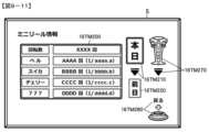
所定条件が成立したときに(メニュー画面が表示されているときに、スティックコントローラ31A及びプッシュボタン31Bの操作により「ミニリール情報」のアイコンが選択されたこと)、前記表示履歴に関する情報(成立役が「ベル」となる当選確率)を表示可能な履歴表示手段(ミニリール情報16TM200を表示する画像表示装置5)と、を備える
ことを特徴とする。
このような構成によれば、遊技者が設定値を推測するために、特別表示の表示履歴に関する情報を容易に把握することができる。
The gaming machine of means A8 is
Any gaming machine selected from means A1 to means A7,
a storage means (RAM 122 of the effect control board 12) for storing the display history of the special display (accumulated number of times the combination of mini-slot symbols in which the winning hand is "bell" has been stopped and displayed);
When a predetermined condition is satisfied (when the menu screen is displayed, the "mini reel information" icon is selected by operating the
According to such a configuration, the player can easily grasp the information about the display history of the special display in order to guess the set value.
手段A9の遊技機は、
手段A1~手段A8から選択される何れかの遊技機であって、
装飾識別情報(飾り図柄)の可変表示と、該装飾識別情報よりも視認性が低い縮小識別情報(小図柄)の可変表示とを実行可能な可変表示手段(演出制御用CPU120)と、
装飾識別情報及び縮小識別情報とは異なる特殊識別情報(ミニスロット図柄)の可変表示を実行可能な特殊可変表示実行手段(演出制御用CPU120)と、
遊技者にとって有利な有利状態(大当り遊技状態)に制御可能な有利状態制御手段(遊技制御用マイクロコンピュータ100)と、
表示手段と、を備え、
前記可変表示手段は、装飾識別情報の可変表示を前記表示手段の表示領域のうちの第1領域(画面中央の飾り図柄表示エリア5L、5C、5R)で実行可能であるとともに、縮小識別情報の可変表示を前記表示手段の表示領域のうちの第2領域(画面右上部の小図柄表示エリア5l、5c、5r)で実行可能であり、
前記特殊可変表示実行手段は、特殊識別情報の可変表示を前記表示手段の表示領域のうちの第3領域(画面中央下部)で実行可能であり、
前記表示手段の第1領域及び第3領域には、設定示唆に関連する表示を表示可能である一方、前記第2領域には、設定示唆に関連する表示を制限する(小図柄表示エリア5l、5c、5rには、ミニスロット図柄等の設定示唆に対応する画像を表示させない)
このような構成によれば、設定示唆に関する興趣を向上させることができるとともに、第2領域における縮小識別情報の可変表示を適切に実行することができる。
The gaming machine of means A9 is
Any gaming machine selected from means A1 to means A8,
variable display means (effect control CPU 120) capable of performing variable display of decoration identification information (decoration pattern) and variable display of reduced identification information (small pattern) with lower visibility than the decoration identification information;
Special variable display execution means (effect control CPU 120) capable of variable display of special identification information (mini-slot symbols) different from decoration identification information and reduced identification information;
Advantageous state control means (game control microcomputer 100) capable of controlling an advantageous state (jackpot game state) advantageous to the player;
a display means;
The variable display means can variably display the decoration identification information in the first area (decorative
The special variable display executing means can execute the variable display of the special identification information in a third area (lower center of the screen) of the display areas of the display means,
In the first area and the third area of the display means, it is possible to display the display related to the setting suggestion, while in the second area, the display related to the setting suggestion is limited (small
According to such a configuration, it is possible to improve interest in setting suggestions, and to appropriately perform variable display of reduced identification information in the second area.
手段A10の遊技機は、
手段A1~手段A9から選択される何れかの遊技機であって、
遊技者にとって有利度が異なる複数の設定値(大当り判定用乱数の範囲が異なる設定値1~6)のうちのいずれかの設定値に設定可能な設定手段(遊技制御用マイクロコンピュータ100)と、
可変表示(変動表示)を実行可能な可変表示手段(遊技制御用マイクロコンピュータ100、演出制御用CPU120)と、
遊技者にとって有利な有利状態(大当り遊技状態)に制御可能な有利状態制御手段(遊技制御用マイクロコンピュータ100)と、
表示手段(演出制御用CPU120、画像表示装置5)と、を備え、
前記表示手段は、前記設定手段に関する設定示唆に対応する特別表示(成立役が「ベル」となるミニスロット図柄の組合せ)と、前記有利状態の制御の示唆に対応する特定表示(成立役が「スイカ」、「チェリー」、または「7揃い」となるミニスロット図柄の組合せ、「表示なし」、「CHANCE」、「激熱」、または「FEVER」の図柄)とを表示可能であり、
可変表示期間が所定期間のときには前記特別表示を表示可能であり(変動パターン(変動時間)が、非リーチはずれ(10秒)、ノーマルリーチはずれ(30秒)、またはノーマルリーチ大当り(30秒)の場合、成立役が「ベル」となるミニスロット図柄の組合せを停止表示させることが可能であり)、可変表示期間が前記所定期間よりも長いときには前記特別表示を表示した後に前記特定表示を表示可能である(変動パターン(変動時間)がスーパーリーチはずれ(120秒)またはスーパーリーチ大当り(120秒)の場合、成立役が「ベル」となるミニスロット図柄の組合せを停止表示させた後に、成立役が「スイカ」、「チェリー」、または「7揃い」となるミニスロット図柄の組合せを停止表示させ、さらに、「表示なし」、「CHANCE」、「激熱」、または「FEVER」の図柄を停止表示させることが可能である)ことを特徴とする。
このような構成によれば、特別表示を特定表示よりも優先して表示させることが可能であるため、設定示唆に関する興趣を向上させることができる。
The gaming machine of means A10 is
Any gaming machine selected from means A1 to means A9,
A setting means (game control microcomputer 100) capable of setting one of a plurality of set values (set
Variable display means (
Advantageous state control means (game control microcomputer 100) capable of controlling an advantageous state (jackpot game state) advantageous to the player;
Display means (
The display means provides a special display corresponding to the setting suggestion regarding the setting means (a combination of mini-slot symbols in which the winning hand is "Bell") and a specific display corresponding to the suggestion of control of the advantageous state (a winning hand is "Bell"). "Watermelon", "Cherry", or a combination of mini-slot symbols that are "7 matching", "No display", "CHANCE", "Extreme heat", or "FEVER" symbols) can be displayed,
When the variable display period is a predetermined period, the special display can be displayed (if the variation pattern (variation time) is non-reach loss (10 seconds), normal reach loss (30 seconds), or normal reach big hit (30 seconds), It is possible to stop display the combination of mini-slot symbols in which the winning hand is "Bell"), and when the variable display period is longer than the predetermined period, the specific display can be displayed after the special display is displayed. (If the variation pattern (variation time) is Super Reach Lost (120 seconds) or Super Reach Big Hit (120 seconds), after stopping the combination of mini-slot symbols in which the winning hand is "Bell", the winning hand is " A combination of mini-slot symbols of "watermelon", "cherry", or "7 matching" is stopped and displayed, and symbols of "no display", "CHANCE", "extreme heat", or "FEVER" are stopped and displayed. is possible).
According to such a configuration, since it is possible to display the special display with priority over the specific display, it is possible to improve interest in setting suggestion.
手段B1の遊技機(パチンコ遊技機1)は、
遊技者にとって有利度が異なる複数の設定値(大当り判定用乱数の範囲が異なる設定値1~6)のうちのいずれかの設定値に設定可能な設定手段(遊技制御用マイクロコンピュータ100)と、
可変表示(変動表示)を実行可能な可変表示手段(遊技制御用マイクロコンピュータ100、演出制御用CPU120)と、
遊技者にとって有利な有利状態(大当り遊技状態)に制御可能な有利状態制御手段(遊技制御用マイクロコンピュータ100)と、
表示手段(演出制御用CPU120、画像表示装置5)と、を備え、
前記表示手段は、前記設定手段に関する設定示唆に対応する特別表示(成立役が「ベル」となるミニスロット図柄の組合せ)と、前記有利状態の制御の示唆に対応する特定表示(成立役が「スイカ」、「チェリー」、または「7揃い」となるミニスロット図柄の組合せ、「表示なし」、「CHANCE」、「激熱」、または「FEVER」の図柄)とを特定領域に表示可能であり、
可変表示に対応する対応表示(アクティブ表示16TM003)を表示可能な対応表示手段(演出制御用CPU120、画像表示装置5)と、
前記特定表示が前記特定領域に表示された(図9-9(8)に示すように、ミニスロット図柄表示領域5L1、5C1、5R1に、成立役が「チェリー」となるミニスロット図柄の組合せを停止表示させた後に、図9-10(10)に示すように、ミニスロット図柄表示領域5LCR1に、「激熱」の文字図柄を停止表示させる)ことに対応して前記対応表示の態様を変化させる変化演出(図9-10(11)及び(12)に示すように、ミニスロット図柄の文字(「激熱」)と同じ文字を示す文字アイコンをアクティブ表示16TM030に付加する第2変化演出)を実行可能な演出実行手段(演出制御用CPU120)と、を備える
ことを特徴とする遊技機。
このような構成によれば、設定示唆に対応する特別表示を表示可能な遊技機で、特定表示が特定領域に表示されたことに対応して変化演出を実行可能であるため、演出の興趣を向上させることができる。
The gaming machine (pachinko gaming machine 1) of means B1 is
A setting means (game control microcomputer 100) capable of setting one of a plurality of set values (set
Variable display means (
Advantageous state control means (game control microcomputer 100) capable of controlling an advantageous state (jackpot game state) advantageous to the player;
Display means (
The display means provides a special display corresponding to the setting suggestion regarding the setting means (a combination of mini-slot symbols in which the winning hand is "Bell") and a specific display corresponding to the suggestion of control of the advantageous state (a winning hand is "Bell"). "Watermelon", "Cherry", or a combination of mini-slot symbols of "7 matching", symbols of "No display", "CHANCE", "Extreme heat", or "FEVER") can be displayed in a specific area. ,
Corresponding display means (
In the mini-slot symbol display areas 5L1, 5C1, and 5R1 where the specific display is displayed in the specific area (as shown in FIG. 9-9(8), a combination of mini-slot symbols in which the winning hand is "Cherry" is displayed. After the stop display, as shown in FIG. 9-10 (10), the character pattern of "hot heat" is stopped and displayed in the mini-slot pattern display area 5LCR1. change effect (as shown in FIGS. 9-10 (11) and (12), a character icon indicating the same character as the mini-slot pattern character (“hot heat”) is added to the active display 16TM030) and effect execution means (effect control CPU 120) capable of executing
According to such a configuration, in a gaming machine capable of displaying a special display corresponding to a setting suggestion, a change effect can be executed in response to the specific display being displayed in the specific area. can be improved.
手段B2の遊技機は、
手段B1の遊技機であって、
前記対応表示(アクティブ表示)の態様として複数種類の特別態様(通常態様、青色態様、赤色態様)があり、
前記演出実行手段(演出制御用CPU120)は、前記対応表示の前記特別態様を変化させる特別演出(第1変化演出)を実行可能である
ことを特徴とする遊技機。
このような構成によれば、特別態様の対応表示が変化することを遊技者に期待させることができる。
The gaming machine of means B2 is
A gaming machine of means B1,
There are multiple types of special modes (normal mode, blue mode, red mode) as modes of the corresponding display (active display),
The game machine, wherein the effect execution means (effect control CPU 120) can execute a special effect (first change effect) for changing the special mode of the corresponding display.
According to such a configuration, it is possible to make the player expect that the display corresponding to the special mode will change.
手段B3の遊技機は、
手段B1又は手段B2の遊技機であって、
前記演出実行手段(演出制御用CPU120)は、前記変化演出(第2変化演出)として、前記変化演出の対象となる対応表示(アクティブ表示)に作用する演出を実行可能である(図9-10(11)及び(12)に示すように、ミニスロット図柄表示エリア5LCR1に停止表示されたミニスロット図柄(「激熱」)が、ミニスロット16TM30から飛び出してアクティブ表示16TM003に当たったことを示すエフェクト画像が表示された後に、ミニスロット図柄表示エリア5LCR1に停止表示されたミニスロット図柄の文字(「激熱」)と同じ文字を示す文字アイコンがアクティブ表示16TM030に付加される)
ことを特徴とする。
このような構成によれば、変化演出の興趣を向上させることができる。
The gaming machine of means B3 is
A game machine of means B1 or means B2,
The effect execution means (effect control CPU 120) can execute an effect acting on a corresponding display (active display) to be subjected to the change effect as the change effect (second change effect) (FIGS. 9-10). As shown in (11) and (12), an effect indicating that the mini-slot symbol ("Geki-netsu") stopped and displayed in the mini-slot symbol display area 5LCR1 jumps out of the mini-slot 16TM30 and hits the active display 16TM003. After the image is displayed, a character icon showing the same character as the character ("Geki-netsu") of the mini-slot symbol displayed stopped in the mini-slot symbol display area 5LCR1 is added to the active display 16TM030).
It is characterized by
According to such a configuration, it is possible to improve the interest of the changing presentation.
手段B4の遊技機は、
手段B1~手段B3の何れかの遊技機であって、
前記特定表示は複数種類あり(第1のミニスロット可変表示の成立役として「はずれ」、「スイカ」、「チェリー」、「7揃い」があり、第2のミニスロット可変表示の表示結果として「表示なし」、「CHANCE」、「激熱」、「FEVER」があり)、
前記特定表示の種類に応じて、前記変化演出の対象となる対応表示の態様が異なる割合で決定される(図9-7(K)及び(L)に示すように、期待度予告演出における第1のミニスロット可変表示の成立役は「はずれ」、「スイカ」、「チェリー」、及び「7揃い」の何れに決定され、何れの成立役に決定されたかに応じて、第2のミニスロット可変表示の表示結果が「表示なし」、「CHANCE」、「激熱」、及び「FEVER」の何れになるのかの選択割合が異なっている。そして、第2のミニスロット可変表示の表示結果とアクティブ表示16TM003に付加される文字アイコンの態様とは合致しているので、期待度予告演出における第1のミニスロット可変表示の成立役が何れに決定されたかに応じて、アクティブ表示16TM003に付加される文字アイコンの態様が何れになるのかの割合が異なる)
ことを特徴とする。
このような構成によれば、特定表示の種類と対応表示の態様に関連性を持たせることができ、演出の興趣を向上させることができる。
The gaming machine of means B4 is
Any gaming machine of means B1 to means B3,
There are a plurality of types of the specific display ("missing", "watermelon", "cherry", and "7 matching" are available as the establishment combination of the first variable display of the mini-slot, and " No display”, “CHANCE”, “hot”, “FEVER”),
Depending on the type of the specific display, the aspect of the corresponding display to be the target of the change effect is determined at a different rate (as shown in FIGS. 9-7 (K) and (L), the first The winning hand for the variable display of the mini-slots of 1 is determined to be any one of "miss", "watermelon", "cherry", and "seven matching", and depending on which winning hand is determined, the second mini-slot is selected. The display result of the variable display is different from the display result of the second mini-slot variable display, and the display result of the second mini-slot variable display is different. Since it matches the form of the character icon added to the active display 16TM003, it is added to the active display 16TM003 according to which hand is determined to establish the first mini-slot variable display in the expectation level announcement effect. The ratio of which character icon mode will be different)
It is characterized by
According to such a configuration, the type of specific display and the mode of corresponding display can be associated with each other, and the entertainment of the presentation can be improved.
手段B5の遊技機は、
手段B1~手段B4から選択される何れかの遊技機であって、
演出を制御する演出制御手段(演出制御用CPU120)を備え、
前記演出制御手段は、前記可変表示手段(遊技制御用マイクロコンピュータ100、演出制御用CPU120)による可変表示(変動表示)が実行されるときに、設定値に応じて異なる割合で前記特別表示を表示するか否かを決定し、該決定を行った後に前記特定表示を表示するか否かを決定する(図9-5に示すように、ステップS16TM2000で第1設定示唆演出の実行有無を決定した後に、ステップS16TM2020で期待度予告演出の実行有無を決定する)
ことを特徴とする。
このような構成によれば、特別表示を表示するか否かを決定した後に、特定表示を表示するか否かを決定するので、特別表示を優先した適切な演出制御が可能となる。
The gaming machine of means B5 is
Any gaming machine selected from means B1 to means B4,
Provided with production control means (production control CPU 120) for controlling production,
When the variable display means (
It is characterized by
According to such a configuration, after determining whether or not to display the special display, it is determined whether or not to display the specific display.
手段B6の遊技機は、
手段B1~手段B5から選択される何れかの遊技機であって、
前記可変表示手段(演出制御用CPU120)は、装飾識別情報の可変表示(飾り図柄の変動表示)を実行可能であり、
前記表示手段(演出制御用CPU120、画像表示装置5)は、特定領域(ミニスロット図柄表示エリア5L1、5C1、5R1、または、5LCR1)において前記装飾識別情報とは異なる情報の可変表示(ミニスロット図柄の可変表示)を実行可能であり、当該特定領域に前記特別表示(成立役が「ベル」となるミニスロット図柄の組合せ)または前記特定表示(成立役が「スイカ」、「チェリー」、もしくは「7揃い」となるミニスロット図柄の組合せ、または、「CHANCE」、「激熱」、もしくは「FEVER」の文字図柄)、もしくは所定表示(成立役が「はずれ」となるミニスロット図柄の組合せ、または、「表示なし」の図柄)を表示可能である
ことを特徴とする。
このような構成によれば、表示手段の特定領域において実行される演出の興趣を向上させることができる。
The gaming machine of means B6 is
Any gaming machine selected from means B1 to means B5,
The variable display means (production control CPU 120) is capable of variable display of decoration identification information (variable display of decorative patterns),
The display means (
According to such a configuration, it is possible to improve the interest of the presentation executed in the specific area of the display means.
手段B7の遊技機は、
手段B1~手段B6から選択される何れかの遊技機であって、
前記可変表示手段(演出制御用CPU120)は、装飾識別情報の可変表示(飾り図柄の変動表示)を実行可能であり、
前記表示手段(演出制御用CPU120)は、特定領域(ミニスロット図柄表示エリア5L1、5C1、5R1)において前記装飾識別情報とは異なる情報の可変表示(ミニスロット図柄の変動表示)を実行可能であり、
前記特定領域において実行される可変表示の態様が特殊態様(フリーズ態様)となったときには、特殊態様(フリーズ態様)とならなかったときよりも前記有利状態(大当り遊技状態)に制御される割合が高い(図9-7(K)に示すように、ミニスロット図柄がフリーズ態様の変動表示を行うときの成立役は、「チェリー(フリーズ)」又は「7揃い(フリーズ)」となり、「チェリー」以上の成立役(「チェリー」又は「7揃い」)が確定するので、ミニスロット図柄が通常態様の変動表示を行うときよりも、大当り遊技状態に制御される期待度が高くなっている)
ことを特徴とする。
このような構成によれば、可変表示の態様が特殊態様となることにより、遊技者を表示手段に注目させることができる。
The gaming machine of means B7 is
Any gaming machine selected from means B1 to means B6,
The variable display means (production control CPU 120) is capable of variable display of decoration identification information (variable display of decorative patterns),
The display means (effect control CPU 120) is capable of executing variable display of information different from the decoration identification information (variable display of mini-slot symbols) in specific areas (mini-slot symbol display areas 5L1, 5C1, 5R1). ,
When the aspect of the variable display executed in the specific area becomes a special aspect (freeze aspect), the ratio of being controlled to the advantageous state (jackpot game state) is higher than when the special aspect (freeze aspect) does not occur. High (As shown in FIG. 9-7 (K), when the mini-slot symbols perform the variable display of the freeze mode, the established hand is "cherry (freeze)" or "7 matching (freeze)", and "cherry" Since the above winning combination (“cherry” or “7 matching”) is confirmed, the degree of expectation that the mini-slot symbols will be controlled to the jackpot game state is higher than when the mini-slot symbols are displayed in a normal mode.)
It is characterized by
According to such a configuration, it is possible to draw the player's attention to the display means by changing the variable display mode to a special mode.
手段B8の遊技機は、
手段B1~手段B7から選択される何れかの遊技機であって、
前記特定表示は複数種類あり(成立役として「スイカ」、「チェリー」、及び「7揃い」があり、表示結果として「表示なし」、「CHANCE」、「激熱」、及び「FEVER」があり)、
前記特定表示の種類に応じて前記有利状態に制御される割合が異なる(図9-7(K)に示すように、大当り遊技状態に制御される期待度は、「スイカ」<「チェリー」<「7揃い」の順で高くなっている)
ことを特徴とする。
このような構成によれば、特定表示の種類に関心を持たせることができる。
The gaming machine of means B8 is
Any gaming machine selected from means B1 to means B7,
There are multiple types of specific indications ("watermelon", "cherry", and "7 sets" are available as established roles, and "no indication", "CHANCE", "extreme heat", and "FEVER" are available as display results). ),
The ratio of control to the advantageous state differs depending on the type of the specific display (as shown in FIG. 9-7 (K), the degree of expectation to be controlled to the jackpot game state is "watermelon"<"cherry"< It is higher in the order of “7 matching”)
It is characterized by
According to such a configuration, it is possible to make the user interested in the type of specific display.
手段B9の遊技機は、
手段B1~手段B8から選択される何れかの遊技機であって、
前記特別表示の表示履歴(成立役が「ベル」となるミニスロット図柄の組合せが停止表示した累計回数)を記憶する記憶手段(演出制御基板12のRAM122)と、
所定条件が成立したときに(メニュー画面が表示されているときに、スティックコントローラ31A及びプッシュボタン31Bの操作により「ミニリール情報」のアイコンが選択されたこと)、前記表示履歴に関する情報(成立役が「ベル」となる当選確率)を表示可能な履歴表示手段(ミニリール情報16TM200を表示する画像表示装置5)と、を備える
ことを特徴とする。
このような構成によれば、遊技者が設定値を推測するために、特別表示の表示履歴に関する情報を容易に把握することができる。
The gaming machine of means B9 is
Any gaming machine selected from means B1 to means B8,
a storage means (RAM 122 of the effect control board 12) for storing the display history of the special display (accumulated number of times the combination of mini-slot symbols in which the winning hand is "bell" has been stopped and displayed);
When a predetermined condition is satisfied (when the menu screen is displayed, the "mini reel information" icon is selected by operating the
According to such a configuration, the player can easily grasp the information about the display history of the special display in order to guess the set value.
手段B10の遊技機は、
手段B1~手段B9から選択される何れかの遊技機であって、
前記表示手段(演出制御用CPU120)は、特殊領域(画像表示装置5の画面左下部)に設定値を示唆する特殊表示(変動回数表示16TM040)を表示可能であり、
前記特殊表示が表示される割合と、前記特別表示が表示される割合とは異なり(第1設定示唆演出は1回の変動表示毎に実行抽選を行っており、第2設定示唆演出は25回の変動表示毎に実行抽選を行っており)、
前記特殊表示により示唆された設定値が当該遊技機の設定値に対応する割合と、前記特別表示により示唆された設定値が当該遊技機の設定値に対応する割合とは異なる(図9-6(G)に示すように、第1設定示唆演出の実行割合が、3%(設定値1)~8%(設定値6)であるのに対して、図9-7(M)に示すように、第2設定示唆演出の実行割合は、10%(設定値1)~20%(設定値6)であるため、第1設定示唆演出と第2設定示唆演出とでは、実際の演出実行割合に基づいて推測される設定値が当該遊技機の設定値と合致する割合が異なる)
ことを特徴とする。
このような構成によれば、特別表示であるか又は特殊表示であるかに応じて、示唆された設定値が当該遊技機の設定値に対応する割合が異なるため、何れの表示によって設定値を示唆されるかに注目させることができる。
The gaming machine of means B10 is
Any gaming machine selected from means B1 to means B9,
The display means (effect control CPU 120) can display a special display (variation number display 16TM040) that suggests a set value in a special area (bottom left of the screen of the image display device 5),
The rate at which the special display is displayed differs from the rate at which the special display is displayed (the first setting suggestion effect is performed by drawing lots for each variable display, and the second setting suggestion effect is 25 times Execution lottery is performed for each change display),
The ratio of the setting value suggested by the special display corresponding to the setting value of the gaming machine differs from the ratio of the setting value suggested by the special display corresponding to the setting value of the gaming machine (Fig. 9-6 As shown in (G), the execution ratio of the first setting suggestion effect is 3% (set value 1) to 8% (set value 6), whereas as shown in FIG. 9-7 (M) In addition, since the execution ratio of the second setting suggestion effect is 10% (set value 1) to 20% (set value 6), the actual effect execution ratio between the first set suggestion effect and the second set suggestion effect The ratio of the setting value estimated based on the match with the setting value of the game machine is different)
It is characterized by
According to such a configuration, the ratio of the suggested setting value to the setting value of the gaming machine differs depending on whether the special display is a special display or not. You can draw attention to what is suggested.
また、後述する発明を実施するための形態には、以下の手段(1)~(7)に係る発明が含まれる。従来より、遊技機において、特開2016-2224号公報に示されているような、可変表示ゲームにおける表示図柄の可変表示が完全に停止した際の停止図柄態様が特定表示態様となったときに、遊技者にとって有利な有利状態(大当り遊技状態)となる。例えば、大当り遊技状態となった遊技機は、大入賞口またはアタッカと呼ばれる特別電動役物を開放状態とし、遊技者に対して遊技球の入賞が極めて容易となる状態を一定時間継続的に提供する。こうした遊技機では、可変表示の表示結果が導出表示される前に、有利状態に制御される期待度を遊技者に報知する様々な種類の演出が実行される。 Further, the modes for carrying out the invention described later include inventions according to the following means (1) to (7). Conventionally, in a game machine, when the variable display of display symbols in a variable display game is completely stopped, as disclosed in Japanese Patent Application Laid-Open No. 2016-2224, when the stop symbol mode becomes a specific display mode , it becomes an advantageous state (jackpot game state) that is advantageous for the player. For example, a gaming machine in a jackpot game state opens a special electric accessory called a jackpot or an attacker, and continuously provides a state in which it is extremely easy for a player to win a game ball for a certain period of time. do. In such a gaming machine, various types of effects are executed to notify the player of the degree of expectation of being controlled to an advantageous state before the display result of the variable display is derived and displayed.
このような遊技機として、例えば、使用する色数を減らして白黒モードで演出を実行するものがある As such a game machine, for example, there is a game machine that reduces the number of colors used and executes production in black and white mode.
しかしながら、単に色数を減らしたに過ぎないため、遊技興趣を向上させるといった点で改善の余地があった。上記実状に鑑みてなされたものであり、遊技興趣を向上させることができる遊技機の提供を目的とする。 However, since the number of colors is merely reduced, there is still room for improvement in terms of enhancing the amusement of the game. SUMMARY OF THE INVENTION It is an object of the present invention to provide a game machine capable of improving the enjoyment of a game.
(1)上記目的を達成するための、別態様による遊技機として、可変表示を行い、遊技者にとって有利な有利状態に制御可能な遊技機(例えば、パチンコ遊技機1など)であって、
可変表示に関する特定表示を表示手段に表示可能な特定表示手段(例えば、保留表示やアクティブ表示を行う演出制御用CPU120など)と、
前記特定表示の表示色を変化させる変化演出を実行可能な変化演出実行手段(例えば、074AKS035の処理を実行する演出制御用CPU120など)と、を備え、
前記特定表示の表示色は、前記有利状態に制御される期待度に応じて異なり(例えば、「赤」の段階までアクティブ表示(保留表示の段階で変化する場合も含む)が変化した場合には、可変表示結果が必ず「大当り」となるなど)、
通常演出状態と、該通常演出状態から移行可能な演出状態であって、前記通常演出状態よりも前記有利状態に制御される割合が高い特定演出状態と、があり(例えば、モノクロ演出を実行する場合、モノクロ演出を実行しない場合よりも可変表示結果が大当りとなる期待度が高いなど)、
前記特定演出状態は、前記表示手段にて表示される、少なくとも前記特定表示を含む表示対象の少なくとも一部の色数が、前記通常演出状態よりも少なく表示される演出状態であり(例えば、演出制御基板12の側にてモノクロ出力処理を行うことで、画像表示装置3にて表示される対象の画像をモノクロ態様に変更する演出であり、予め記憶されている演出画像を表示する際に使用する色数を通常演出状態より少ない色数で表示する演出であるなど)、
前記通常演出状態のときに前記変化演出実行手段により前記変化演出を実行した場合には、前記特定表示の表示色を前記有利状態に制御される期待度に応じた表示色へ変化させる一方で、前記特定演出状態のときに前記変化演出手段により前記変化演出を実行した場合には、前記有利状態に制御される期待度に関わらず、前記特定表示の表示色を変化させずに共通の表示色とし(例えば、特定演出状態中(モノクロ演出フラグがオン状態である場合)、モノクロ出力処理が行われていることから、成功態様の変化演出が実行されても、大当り期待度に関わらず、保留表示やアクティブ表示が「白」にて表示される。一方、モノクロ演出の実行中でない通常演出状態では、表示態様変化パターンに従い、期待度に応じた表示色にて表示されるなど)、
前記特定演出状態から前記通常演出状態に移行したときに、前記特定表示の表示色を前記有利状態に制御される期待度に応じた表示色で表示する(例えば、ステップ074AKS032にてモノクロ態様での表示対象となっていた対象画像に対する使用色数が通常の色数に戻り、変化演出により表示態様が変化した保留表示やアクティブ表示を、変化後の表示色で表示するなど)、
ことを特徴とする。
(1) As a gaming machine according to another mode for achieving the above object, a gaming machine (for example,
Specific display means (for example,
A change effect execution means capable of executing a change effect that changes the display color of the specific display (for example, an
The display color of the specific display differs depending on the degree of expectation to be controlled to the advantageous state (for example, when the active display (including the case where it changes at the stage of pending display) changes to the "red" stage , the variable display result will always be a "jackpot", etc.),
There are a normal effect state and a specific effect state, which is a state of effect that can be shifted from the normal effect state, and in which the ratio of control to the advantageous state is higher than that of the normal effect state (for example, a monochrome effect is executed. In this case, the expectation that the variable display result will be a big hit is higher than when the monochrome effect is not executed, etc.)
The specific rendering state is a rendering state in which the number of colors of at least a part of the display target including at least the specific display displayed on the display means is smaller than that of the normal rendering state (for example, rendering By performing monochrome output processing on the
When the change effect execution means executes the change effect in the normal effect state, while changing the display color of the specific display to a display color according to the degree of expectation controlled to the advantageous state, When the change performance is executed by the change performance means in the specific performance state, a common display color is used without changing the display color of the specific display regardless of the degree of expectation to be controlled to the advantageous state. (For example, during the specific effect state (when the monochrome effect flag is on), since the monochrome output process is being performed, even if the change effect of the success mode is executed, regardless of the degree of expectation of the big hit, hold The display and active display are displayed in "white".On the other hand, in the normal effect state where the monochrome effect is not being executed, the display color is displayed according to the degree of expectation according to the display mode change pattern, etc.),
When shifting from the specific effect state to the normal effect state, the display color of the specific display is displayed in a display color according to the degree of expectation controlled to the advantageous state (for example, in step 074AKS032, the display color is displayed in a monochrome mode. The number of colors used for the target image that was the display target returns to the normal number of colors, and the suspended display and active display whose display mode has changed due to the change effect are displayed in the changed display color, etc.)
It is characterized by
このような構成によれば、色による期待度報知を好適に行うことができ、遊技興趣を向上させることができる。 According to such a configuration, the degree of expectation can be appropriately notified by color, and the amusement of the game can be improved.
(2)上記(1)に記載の遊技機において、
前記共通の表示色は、前記通常演出状態および前記特定演出状態において前記変化演出が実行される前に高い割合で表示される表示色である(例えば、「白」で表示するなど)、
ようにしてもよい。
(2) In the gaming machine described in (1) above,
The common display color is a display color that is displayed at a high rate before the change effect is executed in the normal effect state and the specific effect state (for example, it is displayed as "white"),
You may do so.
このような構成によれば、色による期待度報知を好適に行うことができ、遊技興趣を向上させることができる。 According to such a configuration, the degree of expectation can be appropriately notified by color, and the amusement of the game can be improved.
(3)上記(1)または(2)に記載の遊技機において、
実行中の演出に応じて発光可能な発光手段(例えば、遊技効果ランプ9など)をさらに備え、
前記発光手段は、前記特定演出状態のときには、前記表示手段にて表示される表示対象の色数に対応した色数にて発光する(例えば、ステップ074AKS056にてモノクロ態様の画像の色数に対応した色数とするなど)、
ようにしてもよい。
(3) In the gaming machine described in (1) or (2) above,
Furthermore, a light emitting means (for example, a
The light emitting means emits light in the number of colors corresponding to the number of colors to be displayed on the display means in the specific effect state (for example, in step 074AKS056, the number of colors corresponding to the number of colors of the monochrome image is displayed). number of colors, etc.),
You may do so.
このような構成によれば、特定演出状態であることを際立たせることができ遊技興趣を向上させることができる。 According to such a configuration, it is possible to emphasize that the game is in the specific effect state, thereby improving the game interest.
(4)上記(1)~(3)のいずれか1つに記載の遊技機において、
前記特定演出状態のときには、前記表示手段にて表示される前記特定表示および背景画像の色数を、前記通常演出状態のときよりも減少させる(例えば、ステップ074AKS056の処理にて、モノクロ演出の実行(モノクロ出力処理)を開始することで、保留表示やアクティブ表示、背景画像などといった、モノクロ態様の対象の画像をモノクロ態様で表示するなど)、
ようにしてもよい。
(4) In the gaming machine according to any one of (1) to (3) above,
In the specific effect state, the number of colors of the specific display and the background image displayed by the display means is reduced more than in the normal effect state (for example, in the processing of step 074AKS056, the monochrome effect is executed. By starting (monochrome output processing), a monochrome target image such as a suspended display, an active display, a background image, etc. is displayed in a monochrome mode, etc.),
You may do so.
このような構成によれば、特定演出状態であることを際立たせることができ遊技興趣を向上させることができる。 According to such a configuration, it is possible to emphasize that the game is in the specific effect state, thereby improving the game interest.
(5)上記(1)~(4)のいずれか1つに記載の遊技機において、
前記特定演出状態のときには、前記通常演出状態のときに出力されている演出音を無音に制御可能である一方で、該特定演出状態のときに前記変化演出を実行する場合、該変化演出の開始を報知する報知音については出力する(例えば、特定演出状態中、出力音を消音し、変化演出については、実行開始音のみ出力して成功音または失敗音については出力しないなど)、
ようにしてもよい。
(5) In the gaming machine according to any one of (1) to (4) above,
In the specific performance state, the performance sound output in the normal performance state can be controlled silently, and when the change performance is executed in the specific performance state, the change performance is started. (For example, during a specific production state, the output sound is muted, and for the change production, only the execution start sound is output and the success sound or failure sound is not output, etc.),
You may do so.
このような構成によれば、特定演出状態であることを際立たせることができるとともに、変化演出の実行開始を認識させることができる。 According to such a configuration, it is possible to highlight the specific effect state and to recognize the start of execution of the change effect.
(6)上記(1)~(5)のいずれか1つに記載の遊技機において、
前記特定演出状態のときに前記変化演出を実行し、前記特定演出状態から前記通常演出状態に移行したときに、前記特定表示の表示色が変化していた場合、該移行したタイミングで前記特定表示の表示色が変化したことを報知する変化報知音を出力する(例えば、成功音または失敗音については、モノクロ演出が終了したタイミングで出力するなど)、
ようにしてもよい。
(6) In the gaming machine according to any one of (1) to (5) above,
When the changing effect is executed in the specific effect state, and the display color of the specific display is changed when the specific effect state is shifted to the normal effect state, the specific display is at the transition timing. Output a change notification sound that notifies that the display color of has changed (for example, for success or failure sounds, output at the timing when the monochrome effect ends),
You may do so.
このような構成によれば、特定表示が変化したことを認識しやすくすることができ遊技興趣を向上させることができる。 According to such a configuration, it is possible to make it easier to recognize that the specific display has changed, and to improve the amusement of the game.
(7)上記(1)~(6)のいずれか1つに記載の遊技機において、
前記有利状態に制御される期待度を示唆しない特別情報の色数については、前記特定演出状態であっても減少させない(例えば、期待度に応じて抽選して表示する画像ではなく、主基板11の側から送信されたコマンド等による情報を表示するための画像については、モノクロ態様としないなど)、
ようにしてもよい。
(7) In the gaming machine according to any one of (1) to (6) above,
The number of colors of the special information that does not suggest the degree of expectation controlled to the advantageous state is not reduced even in the specific effect state (for example, the
You may do so.
このような構成によれば、特別情報により示唆される内容については特定演出状態であっても認識でき、遊技興趣の低下を防止することができる。 According to such a configuration, it is possible to recognize the content suggested by the special information even in the specific effect state, and prevent the decline in the interest in the game.
尚、本発明は、本発明の請求項に記載された発明特定事項のみを有するものであって良いし、本発明の請求項に記載された発明特定事項とともに該発明特定事項以外の構成を有するものであっても良い。 The present invention may include only the matters specifying the invention described in the claims of the present invention, or may include the matters specifying the invention described in the claims of the present invention as well as the matters specifying the invention other than the matters specifying the invention. It can be anything.
(基本説明)
まず、パチンコ遊技機1の基本的な構成及び制御(一般的なパチンコ遊技機の構成及び制御でもある。)について説明する。
(Basic explanation)
First, the basic configuration and control of the pachinko game machine 1 (also the configuration and control of a general pachinko game machine) will be described.
(パチンコ遊技機1の構成等)
図1は、パチンコ遊技機1の正面図であり、主要部材の配置レイアウトを示す。パチンコ遊技機(遊技機)1は、大別して、遊技盤面を構成する遊技盤(ゲージ盤)2と、遊技盤2を支持固定する遊技機用枠(台枠)3とから構成されている。遊技盤2には、遊技領域が形成され、この遊技領域には、遊技媒体としての遊技球が、所定の打球発射装置から発射されて打ち込まれる。
(Configuration of
FIG. 1 is a front view of the
遊技盤2の所定位置(図1に示す例では、遊技領域の右側方)には、複数種類の特別識別情報としての特別図柄(特図ともいう)の可変表示(特図ゲームともいう)を行う第1特別図柄表示装置4A及び第2特別図柄表示装置4Bが設けられている。これらは、それぞれ、7セグメントのLEDなどからなる。特別図柄は、「0」~「9」を示す数字や「-」などの点灯パターンなどにより表される。特別図柄には、LEDを全て消灯したパターンが含まれてもよい。
At a predetermined position of the game board 2 (in the example shown in FIG. 1, on the right side of the game area), a variable display (also called a special game) of special symbols (also called special symbols) as a plurality of types of special identification information is displayed. A first special
なお、特別図柄の「可変表示」とは、例えば、複数種類の特別図柄を変動可能に表示することである(後述の他の図柄についても同じ)。変動としては、複数の図柄の更新表示、複数の図柄のスクロール表示、1以上の図柄の変形、1以上の図柄の拡大/縮小などがある。特別図柄や後述の普通図柄の変動では、複数種類の特別図柄又は普通図柄が更新表示される。後述の飾り図柄の変動では、複数種類の飾り図柄がスクロール表示又は更新表示されたり、1以上の飾り図柄が変形や拡大/縮小されたりする。なお、変動には、ある図柄を点滅表示する態様も含まれる。可変表示の最後には、表示結果として所定の特別図柄が停止表示(導出又は導出表示などともいう)される(後述の他の図柄の可変表示についても同じ)。なお、可変表示を変動表示、変動と表現する場合がある。 The "variable display" of special symbols means, for example, that a plurality of types of special symbols are variably displayed (the same applies to other symbols described later). Variations include updating display of a plurality of patterns, scrolling display of a plurality of patterns, deformation of one or more patterns, enlargement/reduction of one or more patterns, and the like. In the variation of special symbols and normal symbols, which will be described later, a plurality of types of special symbols or normal symbols are updated and displayed. In the variation of decorative patterns, which will be described later, a plurality of types of decorative patterns are scrolled or updated, and one or more decorative patterns are deformed or enlarged/reduced. Note that the variation also includes a mode in which a certain symbol is displayed blinking. At the end of the variable display, a predetermined special symbol is stopped and displayed (also referred to as derivation or derivation display) as a display result (the same applies to variable display of other symbols to be described later). Variable display may be expressed as variable display or variation.
なお、第1特別図柄表示装置4Aにおいて可変表示される特別図柄を「第1特図」ともいい、第2特別図柄表示装置4Bにおいて可変表示される特別図柄を「第2特図」ともいう。また、第1特図を用いた特図ゲームを「第1特図ゲーム」といい、第2特図を用いた特図ゲームを「第2特図ゲーム」ともいう。なお、特別図柄の可変表示を行う特別図柄表示装置は1種類であってもよい。
The special symbols variably displayed on the first special
また、第1特別図柄表示装置4A及び第2特別図柄表示装置4Bの下方には、遊技領域の右方を狙って発射操作を行う右打ち操作を促すための右打ち表示器26が設けられている。なお、右打ち表示器26は、例えば、LEDによって構成され、主基板11に搭載された遊技制御用マイクロコンピュータ100(具体的には、CPU103)によって点灯制御される(図2参照)。
In addition, below the first special
遊技盤2における遊技領域の中央付近には画像表示装置5が設けられている。画像表示装置5は、例えばLCD(液晶表示装置)や有機EL(Electro Luminescence)等から構成され、各種の演出画像を表示する。画像表示装置5は、プロジェクタ及びスクリーンから構成されていてもよい。画像表示装置5には、各種の演出画像が表示される。
An
例えば、画像表示装置5の画面上では、第1特図ゲームや第2特図ゲームと同期して、特別図柄とは異なる複数種類の装飾識別情報としての飾り図柄(数字などを示す図柄など)の可変表示が行われる。ここでは、第1特図ゲーム又は第2特図ゲームに同期して、「左」、「中」、「右」の各飾り図柄表示エリア5L、5C、5Rにおいて飾り図柄が可変表示(例えば上下方向のスクロール表示や更新表示)される。なお、同期して実行される特図ゲーム及び飾り図柄の可変表示を総称して単に可変表示ともいう。
For example, on the screen of the
また、例えば、画像表示装置5の画面上には、実行が保留されている可変表示に対応する保留表示を表示するための表示エリアが設けられている。本例では、第1特図の可変表示に対応する保留表示を表示するための第1保留表示領域5Aと、第2特図の可変表示に対応する保留表示を表示するための第2保留表示領域5Bとが設けられている。なお、画像表示装置5の画面上には、実行中の可変表示に対応するアクティブ表示を表示するための表示エリアが設けられていてもよい。保留表示及びアクティブ表示を総称して可変表示に対応する可変表示対応表示ともいう。
Further, for example, on the screen of the
また、画像表示装置5の右方には、右打ち操作を促すための右打ち報知用LED37が設けられている。なお、右打ち報知用LED37は、演出制御基板12に搭載された演出制御用CPU120によって点灯制御される(図2参照)。
Further, on the right side of the
保留されている可変表示の数は保留記憶数ともいう。第1特図ゲームに対応する保留記憶数を第1保留記憶数、第2特図ゲームに対応する保留記憶数を第2保留記憶数ともいう。また、第1保留記憶数と第2保留記憶数との合計を合計保留記憶数ともいう。 The number of variable representations that are reserved is also referred to as the number of reserved memories. The reserved memory number corresponding to the first special game is also referred to as the first reserved memory number, and the reserved memory number corresponding to the second special game is also referred to as the second reserved memory number. The sum of the first reserved memory count and the second reserved memory count is also referred to as the total reserved memory count.
また、遊技盤2の所定位置には、複数のLEDを含んで構成された第1保留表示器25Aと第2保留表示器25Bとが設けられ、第1保留表示器25Aは、LEDの点灯個数によって、第1保留記憶数を表示し、第2保留表示器25Bは、LEDの点灯個数によって、第2保留記憶数を表示する。
In addition, at a predetermined position of the
画像表示装置5の下方には、第1始動入賞口を有する入賞球装置6Aが設けられている。第1始動入賞口に入賞した遊技球は、遊技盤2の背面に導かれ、第1始動口スイッチ22Aによって検出される。第1始動口スイッチ22Aによって遊技球が検出された場合には、この検出情報に基づき、所定個数(1個)の遊技球が賞球として払い出される。
Below the
また、第1始動入賞口の右方には、釘の列19が設けられており、遊技領域の右方から流下した遊技球が第1始動入賞口が設けられた領域に進入しないように構成されている。このように、遊技領域の右方から流下した遊技球が進入することを防止する釘の列19が設けられていることによって、遊技領域の左方を狙って遊技球を発射操作(いわゆる左打ち操作)した場合にのみ第1始動入賞口に遊技球が入賞可能に構成されている。
In addition, a row of
なお、本例では、釘の列19が設けられていることにより左打ち操作した場合にのみ第1始動入賞口に遊技球が入賞可能に構成される場合を示しているが、そのような態様にかぎられない。例えば、第1始動入賞口が遊技領域の左方に設けられていることによって左打ち操作した場合にのみ第1始動入賞口に遊技球が入賞可能に構成してもよいし、第1始動入賞口が遊技領域の左方に設けられているとともに釘の列19も設けることによって左打ち操作した場合にのみ第1始動入賞口に遊技球が入賞可能に構成してもよい。
In addition, in this example, only when left-handed operation is performed due to the provision of the
画像表示装置5の右方には、通過ゲート41が設けられている。通過ゲート41を通過した遊技球は、ゲートスイッチ21によって検出される。
A
通過ゲート41の下方には、大入賞口を形成する特別可変入賞球装置7が設けられている。特別可変入賞球装置7は、やや傾斜した状態で左右方向に延在し、遊技球が流下する流路の底面として形成される板状の底面部材を、前後方向に進退移動させることにより、底面部材の下方に位置する大入賞口に遊技球が入賞可能な開状態(開放状態ともいう)と遊技球が入賞不能な閉状態(閉鎖状態ともいう)とに変化させる。特別可変入賞球装置7は、第1特別図柄表示装置4Aまたは第2特別図柄表示装置4Bに特定表示結果(大当り図柄)が導出表示されたときに生起する大当り遊技状態において、底面部材を前方に向けて前進移動させた閉状態から底面部材を後方に向けて後退移動させ、入賞領域となる大入賞口を開状態とする開放制御を実行する。
Below the
特別可変入賞球装置7の下方には、小当り用の特殊入賞口を形成する特殊可変入賞球装置17と、第2始動入賞口を有する可変入賞球装置6Bとが設けられており、図1に示すように、左側に特殊可変入賞球装置17が配置され、その右側に隣り合うように可変入賞球装置6Bが配置されている。これら特殊可変入賞球装置17および可変入賞球装置6Bは、やや傾斜した状態で左右方向に延在し、遊技球が流下する流路の底面として形成される板状の底面部材を、前後方向に進退移動させることにより、底面部材の下方に位置する特殊入賞口や第2始動入賞口に遊技球が入賞可能な開状態(開放状態ともいう)と遊技球が入賞不能な閉状態(閉鎖状態ともいう)とに変化させる。特殊可変入賞球装置17は、第1特別図柄表示装置4Aまたは第2特別図柄表示装置4Bに所定表示結果(小当り図柄)が導出表示されたときに生起する小当り遊技状態において、底面部材を前方に向けて前進移動させた閉状態から底面部材を後方に向けて後退移動させ、入賞領域となる特殊入賞口を開状態とする開放制御を実行する。また、可変入賞球装置6Bは、普通図柄表示器20に当り図柄が導出表示されたときに、底面部材を前方に向けて前進移動させた閉状態から底面部材を後方に向けて後退移動させ、入賞領域となる第2始動入賞口を開状態とする開放制御を実行する。
Below the special variable winning
なお、本例では、特別可変入賞球装置7と特殊可変入賞球装置17と可変入賞球装置6Bとは、同様の構造を有するように形成されている。また、図1に示すように、特別可変入賞球装置7は底面部材が左上から右下に向けてやや傾斜する態様で形成されているので、特別可変入賞球装置7上に落下した遊技球は、特別可変入賞球装置7が閉状態であれば特別可変入賞球装置7上を左上から右下に向けて移動して行き、その下の可変入賞球装置6B上に落下する。
In this example, the special variable winning
また、本例では、可変入賞球装置6Bと比較して特殊可変入賞球装置17の方が若干大きい。また、図1に示すように、特殊可変入賞球装置17および可変入賞球装置6Bは底面部材が右上から左下に向けてやや傾斜する態様で形成されているので、特殊可変入賞球装置17や可変入賞球装置6B上の遊技球は、特殊可変入賞球装置17や可変入賞球装置6Bが閉状態であれば特殊可変入賞球装置17や可変入賞球装置6B上を右上から左下に向けて移動して行く。また、図1に示すように、特殊可変入賞球装置17と可変入賞球装置6Bとは隣り合うように配置されているので、特別可変入賞球装置7に入賞することなく可変入賞球装置6B上に落下した遊技球は、可変入賞球装置6Bの底面部材が後退移動されて第2始動入賞口が開状態となっていれば、遊技球は第2始動入賞口に入賞し、特殊可変入賞球装置17の方には遊技球は流れて行かない。一方、第2始動入賞口が開状態となっていなければ、遊技球は可変入賞球装置6Bの底面部材の上を移動して特殊可変入賞球装置17の方に導かれる。この際に特殊可変入賞球装置17の底面部材が後退移動されて特殊入賞口が開状態となっていれば、遊技球は特殊入賞口に入賞する。さらに、特殊入賞口も開状態となっていなければ、遊技球は特殊可変入賞球装置17の底面部材の上を移動して、そのままアウト口の方へ落下することになる。
Also, in this example, the special variable winning
また、本例では、特別可変入賞球装置7、特殊可変入賞球装置17および可変入賞球装置6Bには、底面部材上を流下する遊技球の流下速度を低下させる複数の規制片が形成されている。本例では、特別可変入賞球装置7、特殊可変入賞球装置17および可変入賞球装置6Bにおいて規制片が設けられていることによって、左上から右下方向または右上から左下方向に向けて流下する遊技球を前後方向成分の動きをもって蛇行するように、遊技球の流下方向を変更させて、その流下にかかる時間を、規制片がない場合よりも遅延させる。
Also, in this example, the special variable winning
なお、本例では、図1に示すように、特殊可変入賞球装置17が左側に配置され、可変入賞球装置6Bが右側に配置されているのであるが、特殊可変入賞球装置17および可変入賞球装置6Bの底面部材が右上方から左下方に緩やかに傾斜するように形成され、底面部材が後退しておらず閉状態である場合には可変入賞球装置6Bの方から特殊可変入賞球装置17の方に向かって遊技球が流れるように構成されているので、この意味で、可変入賞球装置6Bの方が上流側に設けられ、特殊可変入賞球装置17の方が下流側に設けられているといえる。
In this example, as shown in FIG. 1, the special variable winning
大入賞口内には、大入賞口内に入賞した遊技球を検出可能なスイッチ(第1カウントスイッチ23)が設けられている。第1カウントスイッチ23によって遊技球が検出された場合には、この検出情報に基づき、所定個数(例えば15個)の遊技球が賞球として払い出される。従って、特別可変入賞球装置7が開放制御されて大入賞口が開状態となれば、遊技者にとって有利な状態となる。その一方で、特別可変入賞球装置7が閉鎖制御されて大入賞口が閉状態となれば、大入賞口に遊技球を通過(進入)させて賞球を得ることができないため、遊技者にとって不利な状態となる。
A switch (first count switch 23) capable of detecting a game ball that has entered the big winning opening is provided in the big winning opening. When game balls are detected by the
特殊入賞口内には、特殊入賞口内に入賞した遊技球を検出可能なスイッチ(第2カウントスイッチ24)が設けられている。第2カウントスイッチ24によって遊技球が検出された場合には、この検出情報に基づき、所定個数(例えば10個)の遊技球が賞球として払い出される。ここで、特殊可変入賞球装置17において開状態となった特殊入賞口を遊技球が通過(進入)したときには、大入賞口に遊技球が入賞したときと比較すると賞球の数が少ないものの、例えば第1始動入賞口1や第2始動入賞口といった、他の入賞口を遊技球が通過(進入)したときよりも多くの賞球が払い出されるようになっている。従って、特殊可変入賞球装置17が開放制御されて特殊入賞口が開状態となれば、遊技者にとって有利な状態となる。その一方で、特殊可変入賞球装置17が閉鎖制御されて特殊入賞口が閉状態となれば、特殊入賞口に遊技球を通過(進入)させて賞球を得ることができないため、遊技者にとって不利な状態となる。
A switch (second count switch 24) capable of detecting a game ball that has entered the special winning opening is provided in the special winning opening. When game balls are detected by the second count switch 24, a predetermined number (for example 10) of game balls are paid out as prize balls based on this detection information. Here, when the game balls pass through (enter) the special winning opening opened in the special variable winning
また、第2始動入賞口内には、第2始動入賞口内に入賞した遊技球を検出可能な第2始動口スイッチ22Bが設けられている。第2始動口スイッチ22Bによって遊技球が検出された場合には、この検出情報に基づき、所定個数(1個)の遊技球が賞球として払い出される。 In addition, in the second starting winning opening, a second starting opening switch 22B capable of detecting a game ball that has won in the second starting winning opening is provided. When game balls are detected by the second starting port switch 22B, a predetermined number (one) of game balls are paid out as prize balls based on this detection information.
以下、第1始動入賞口と第2始動入賞口とを総称して始動入賞口または始動口ということがある。 Hereinafter, the first start prize-winning opening and the second start prize-winning opening may be collectively referred to as the start prize-winning opening or the start opening.
なお、このパチンコ遊技機1では、通過ゲート41、特別可変入賞球装置7(大入賞口)、可変入賞球装置6B(第2始動入賞口)、および特殊可変入賞球装置17(特殊入賞口)が遊技領域の右方に設けられているので、大当り遊技中やKT状態(いわゆる小当りタイム)中である場合には、遊技者は遊技領域の右方を狙って発射操作(いわゆる右打ち操作)を行う。
In addition, in this
遊技盤2の所定位置(図1に示す例では、遊技領域の左右下方4箇所)には、所定の玉受部材によって常に一定の開放状態に保たれる一般入賞口10が設けられる。この場合には、一般入賞口10のいずれかに進入したときには、所定個数(例えば10個)の遊技球が賞球として払い出される。
At predetermined positions of the game board 2 (in the example shown in FIG. 1, four positions on the left and right sides of the game area), there are provided general winning holes 10 which are always kept open by predetermined ball receiving members. In this case, when the player enters one of the general winning
一般入賞口10を含む各入賞口に遊技球が進入することを「入賞」ともいう。特に、始動口(第1始動入賞口、第2始動入賞口始動口)への入賞を始動入賞ともいう。
Entering a game ball into each winning hole including the general winning
遊技盤2の所定位置(図1に示す例では、遊技領域の左側方)には、普通図柄表示器20が設けられている。一例として、普通図柄表示器20は、7セグメントのLEDなどからなり、特別図柄とは異なる複数種類の普通識別情報としての普通図柄の可変表示を行う。普通図柄は、「0」~「9」を示す数字や「-」などの点灯パターンなどにより表される。普通図柄には、LEDを全て消灯したパターンが含まれてもよい。このような普通図柄の可変表示は、普図ゲームともいう。
A
普通図柄表示器20の上方には、普図保留表示器25Cが設けられている。普図保留表示器25Cは、例えば4個のLEDを含んで構成され、実行が保留されている普図ゲームの数である普図保留記憶数をLEDの点灯個数により表示する。
Above the
なお、このパチンコ遊技機1では、通過ゲート41を遊技球が通過したことにもとづいて普通図柄の変動表示が実行されることから、通過ゲート41は普通始動領域としての役割を担っているのであるが、大当り図柄が導出表示された場合にも通過ゲート41を遊技球が通過したことにもとづいて大当り遊技状態に移行するので、通過ゲート41は作動領域としての役割も担っている。従って、通過ゲート41は、普通始動領域と作動領域との両方の役割を担う兼用ゲートとして構成されている。
In this
遊技盤2の表面には、上記の構成以外にも、遊技球の流下方向や速度を変化させる風車及び多数の障害釘が設けられている。遊技領域の最下方には、いずれの入賞口にも進入しなかった遊技球が取り込まれるアウト口が設けられている。
The surface of the
遊技機用枠3の左右上部位置には、効果音等を再生出力するためのスピーカ8L、8Rが設けられており、さらに遊技領域周辺部には、遊技効果用の枠LED9が設けられている。
遊技盤2の所定位置(図1では図示略)には、演出に応じて動作する可動体32が設けられている。
At a predetermined position (not shown in FIG. 1) of the
遊技機用枠3の右下部位置には、遊技球を打球発射装置により遊技領域に向けて発射するために遊技者等によって操作される打球操作ハンドル(操作ノブ)30が設けられている。
A ball hitting operation handle (operation knob) 30 operated by a player or the like to shoot a game ball toward the game area from the ball shooting device is provided at the lower right portion of the
遊技領域の下方における遊技機用枠3の所定位置には、賞球として払い出された遊技球や所定の球貸機により貸し出された遊技球を、打球発射装置へと供給可能に保持(貯留)する打球供給皿(上皿)が設けられている。上皿の下方には、上皿満タン時に賞球が払い出される打球供給皿(下皿)が設けられている。
At a predetermined position of the
遊技領域の下方における遊技機用枠3の所定位置には、遊技者が把持して傾倒操作が可能なスティックコントローラ31Aが取り付けられている。スティックコントローラ31Aには、遊技者が押下操作可能なトリガボタンが設けられている。スティックコントローラ31Aに対する操作は、コントローラセンサユニット35A(図2参照)により検出される。
A
遊技領域の下方における遊技機用枠3の所定位置には、遊技者が押下操作などにより所定の指示操作を可能なプッシュボタン31Bが設けられている。プッシュボタン31Bに対する操作は、プッシュセンサ35B(図2参照)により検出される。
At a predetermined position of the
パチンコ遊技機1では、遊技者の動作(操作等)を検出する検出手段として、スティックコントローラ31Aやプッシュボタン31Bが設けられるが、これら以外の検出手段が設けられていてもよい。
The
(遊技の進行の概略)
このパチンコ遊技機1では、遊技状態が通常状態である場合には、遊技者は遊技領域の左方を狙って発射操作(いわゆる左打ち操作)を行うのが有利である。パチンコ遊技機1が備える打球操作ハンドル30への遊技者による回転操作により、左打ち操作を行い、入賞球装置6Aに形成された第1始動入賞口に遊技球が進入すると、第1特別図柄表示装置4Aによる第1特図ゲームが開始される。
(Overview of Game Progress)
In this
なお、特図ゲームの実行中の期間や、後述する大当り遊技状態や小当り遊技状態に制御されている期間に、遊技球が始動入賞口へ進入(入賞)した場合(始動入賞が発生したが当該始動入賞に基づく特図ゲームを直ちに実行できない場合)には、当該進入に基づく特図ゲームは所定の上限数(例えば4)までその実行が保留される。 In addition, when the game ball enters (wins) the start winning opening during the period during which the special game is running, or during the period when it is controlled to the big win game state or the small win game state described later (although the start win has occurred If the special game based on the starting prize cannot be executed immediately), the execution of the special game based on the entry is suspended up to a predetermined upper limit number (for example, 4).
第1特図ゲームにおいて、確定特別図柄として特定の特別図柄(大当り図柄、例えば「7」、後述の大当り種別に応じて実際の図柄は異なる。)が停止表示されれば、「大当り」となる。また、大当り図柄とは異なる特別図柄(ハズレ図柄、例えば「-」)が停止表示されれば「ハズレ」となる。なお、第1特図ゲームであっても、極低い割合で小当り図柄が停止表示され、「小当り」となる場合があるように構成してもよい。 In the first special symbol game, if a specific special symbol (big hit symbol, for example, "7", actual symbol differs depending on the type of big hit described later) is stopped and displayed as a fixed special symbol, the result is a "big hit". . Also, if a special symbol (losing symbol, for example, "-") different from the jackpot symbol is stop-displayed, it becomes "losing". It should be noted that even in the first special game, the small winning symbols may be stop-displayed at an extremely low rate, and may be a "small winning".
第1特図ゲームでの表示結果が「大当り」になった後には、遊技球が通過ゲート41を通過したことを条件として、遊技者にとって有利な有利状態として大当り遊技状態に制御される。
After the display result in the first special game becomes ``big win'', on condition that the game ball has passed through the
大当り遊技状態では、特別可変入賞球装置7により形成される大入賞口が所定の態様で開放状態となる。当該開放状態は、所定期間(例えば29秒間や1.8秒間)の経過タイミングと、大入賞口に進入した遊技球の数が所定個数(例えば9個)に達するまでのタイミングと、のうちのいずれか早いタイミングまで継続される。前記所定期間は、1ラウンドにおいて大入賞口を開放することができる上限期間であり、以下、開放上限期間ともいう。このように大入賞口が開放状態となる1のサイクルをラウンド(ラウンド遊技)という。大当り遊技状態では、当該ラウンドが所定の上限回数(15回や2回)に達するまで繰り返し実行可能となっている。
In the jackpot game state, the jackpot formed by the special variable winning
大当り遊技状態においては、遊技者は、遊技球を大入賞口に進入させることで、賞球を得ることができる。従って、大当り遊技状態は、遊技者にとって有利な状態である。大当り遊技状態におけるラウンド数が多い程、また、開放上限期間が長い程遊技者にとって有利となる。 In the jackpot game state, the player can get a prize ball by entering the game ball into the big winning hole. Therefore, the jackpot gaming state is an advantageous state for the player. The larger the number of rounds in the jackpot game state and the longer the upper limit period of opening, the more advantageous the player is.
なお、「大当り」には、大当り種別が設定されている。例えば、大入賞口の開放態様(ラウンド数や開放上限期間)や、大当り遊技状態後の遊技状態(通常状態、確変状態(高確率状態)、KT状態、高ベース状態など)を複数種類用意し、これらに応じて大当り種別が設定されている。大当り種別として、多くの賞球を得ることができる大当り種別や、賞球の少ない又はほとんど賞球を得ることができない大当り種別が設けられていてもよい。 In addition, a jackpot type is set in the "jackpot". For example, we have prepared multiple types of opening modes (number of rounds and upper limit period of opening) of the big winning mouth, and game states after the jackpot game state (normal state, probability variable state (high probability state), KT state, high base state, etc.) , The jackpot type is set according to these. As the jackpot type, there may be provided a jackpot type in which a large number of prize balls can be obtained, and a jackpot type in which a small number of prize balls or almost no prize balls can be obtained.
大当り遊技状態が終了した後は、上記大当り種別に応じて、確変状態やKT状態、高ベース状態に制御されることがある。 After the jackpot game state is finished, the game may be controlled to a variable probability state, a KT state, or a high base state depending on the jackpot type.
確変状態(確率変動状態)では、表示結果が「大当り」となる確率が通常状態よりも高くなる確変制御が実行される。確変状態は、特別図柄の変動効率が向上することに加えて「大当り」となりやすい状態であるので、遊技者にとってさらに有利な状態である。 In the variable probability state (probability variable state), variable probability control is executed in which the probability that the display result is a "jackpot" is higher than in the normal state. The variable probability state is a state in which the variation efficiency of the special symbols is improved, and in addition, a "big hit" is likely to occur, so it is a further advantageous state for the player.
KT状態では、通常状態よりも小当りになりやすいKT制御が実行される。このパチンコ遊技機1では、小当り遊技状態でもある程度の賞球を得ることができるので、大当り遊技状態と比べると得られる賞球が少ないが遊技者にとって有利な状態である。
In the KT state, KT control is executed in which small wins are more likely to occur than in the normal state. In this
高ベース状態では、平均的な特図変動時間(特図を変動させる期間)を通常状態よりも短縮させる制御(時短制御)が実行され(時短状態)、普図ゲームで「普図当り」となる確率を通常状態よりも向上させる等により、第2始動入賞口に遊技球が進入しやすくなる制御(高開放制御、高ベース制御)も実行される。高ベース状態は、特別図柄(特に第2特別図柄)の変動効率が向上する状態であるので、遊技者にとって有利な状態である。 In the high-base state, control (time-saving control) is executed to shorten the average special figure fluctuation time (period of fluctuating special figures) than in the normal state (time saving state). Control (high opening control, high base control) that makes it easier for the game ball to enter the second start winning opening is also executed by improving the probability of becoming more than the normal state. The high base state is a state in which the variation efficiency of the special symbols (especially the second special symbols) is improved, so it is an advantageous state for the player.
確変状態やKT状態、高ベース状態は、所定回数の特図ゲームが実行されたことと、次回の大当り遊技状態が開始されたこと等といった、いずれか1つの終了条件が先に成立するまで継続する。所定回数の特図ゲームが実行されたことが終了条件となるものを、回数切り(回数切り確変等)ともいう。 The variable probability state, the KT state, and the high base state continue until one of the end conditions, such as execution of the special game a predetermined number of times and the start of the next jackpot game state, is met first. do. The end condition that the special figure game of a predetermined number of times has been executed is also referred to as the number of times cut (number of times cut probability variation etc.).
通常状態とは、遊技者にとって有利な大当り遊技状態等の有利状態、確変状態、KT状態、高ベース状態等の特別状態以外の遊技状態のことであり、特図ゲームにおける表示結果が「大当り」となる確率などのパチンコ遊技機1が、パチンコ遊技機1の初期設定状態(例えばシステムリセットが行われた場合のように、電源投入後に所定の復帰処理を実行しなかったとき)と同一に制御される状態である。
The normal state means a game state other than a special state such as an advantageous state such as a jackpot game state that is advantageous to the player, a probability variable state, a KT state, a high base state, etc., and the display result in the special game is "big hit". The
大当り遊技を終了し、遊技状態が確変状態やKT状態、高ベース状態に制御されると、遊技者は遊技領域の右方を狙って発射操作(右打ち操作)を行うのが有利である。パチンコ遊技機1が備える打球操作ハンドル30への遊技者による回転操作により、右打ち操作を行い、遊技球が通過ゲート41を通過すると、普通図柄表示器20による普図ゲームが開始される。なお、前回の普図ゲームの実行中の期間等に遊技球が通過ゲート41を通過した場合(遊技球が通過ゲート41を通過したが当該通過に基づく普図ゲームを直ちに実行できない場合)には、当該通過に基づく普図ゲームは所定の上限数(例えば4)まで保留される。
When the jackpot game ends and the game state is controlled to the variable probability state, KT state, or high base state, it is advantageous for the player to aim at the right side of the game area and perform a shooting operation (right hitting operation). A right-handed operation is performed by a player's rotation operation on a ball-hitting operation handle 30 provided in the
この普図ゲームでは、特定の普通図柄(普図当り図柄)が停止表示されれば、普通図柄の表示結果が「普図当り」となる。その一方、確定普通図柄として、普図当り図柄以外の普通図柄(普図ハズレ図柄)が停止表示されれば、普通図柄の表示結果が「普図ハズレ」となる。「普図当り」となると、可変入賞球装置6Bを所定期間開放状態とする開放制御が行われる(第2始動入賞口が開放状態になる)。 In this normal pattern game, if a specific normal pattern (normal pattern per pattern) is stopped and displayed, the display result of the normal pattern becomes "normal pattern per pattern". On the other hand, if a normal pattern (normal pattern losing pattern) other than the normal pattern per pattern is stop-displayed as the determined normal pattern, the display result of the normal pattern becomes "normal pattern losing". When it comes to "normal game", the variable winning ball device 6B is opened for a predetermined period of time and the opening control is performed (the second start winning opening is opened).
可変入賞球装置6Bに形成された第2始動入賞口に遊技球が進入すると、第2特別図柄表示装置4Bによる第2特図ゲームが開始される。
When the game ball enters the second starting winning hole formed in the variable winning ball device 6B, the second special symbol game by the second special
第2特図ゲームにおいて、確定特別図柄として特定の特別図柄(大当り図柄、例えば「7」、後述の大当り種別に応じて実際の図柄は異なる。)が停止表示されれば、「大当り」となり、大当り図柄とは異なる所定の特別図柄(小当り図柄、例えば「2」)が停止表示されれば、「小当り」となる。また、大当り図柄や小当り図柄とは異なる特別図柄(ハズレ図柄、例えば「-」)が停止表示されれば「ハズレ」となる。 In the second special symbol game, if a specific special symbol (big hit symbol, for example, "7", actual symbol varies depending on the type of big hit described below) is stopped and displayed as a fixed special symbol, it becomes a "big hit", If a predetermined special symbol (a small winning symbol, for example, "2") different from the big winning symbol is stop-displayed, it becomes a "small winning". Also, if a special symbol (losing symbol, for example, "-") different from the big-hit symbol or the small-hit symbol is stop-displayed, it becomes "losing".
第2特図ゲームでの表示結果が「大当り」になった後には、遊技球が通過ゲート41を通過したことを条件として、遊技者にとって有利な有利状態として大当り遊技状態に制御される。第2特図ゲームでの表示結果が「小当り」になった後には、小当り遊技状態に制御される。
After the display result in the second special game becomes ``big hit'', on condition that the game ball has passed through the
小当り遊技状態では、特殊可変入賞球装置17により形成される特殊入賞口が所定の開放態様で開放状態となる。なお、大当り種別と同様に、「小当り」にも小当り種別を設けてもよい。
In the small winning game state, the special winning opening formed by the special variable winning
小当り遊技状態が終了した後は、遊技状態の変更が行われず、特図ゲームの表示結果が「小当り」となる以前の遊技状態に継続して制御される(但し、「小当り」発生時の特図ゲームが、上記回数切りにおける上記所定回数目の特図ゲームである場合には、当然遊技状態が変更される)。 After the small win game state is over, the game state is not changed, and the game state before the display result of the special figure game becomes "small win" is continuously controlled (however, "small win" occurs). If the special game at the time is the special game for the predetermined number of times in the above cut, the game state is naturally changed).
なお、遊技状態は、大当り遊技状態中に遊技球が特定領域(例えば、大入賞口内の特定領域)を通過したことに基づいて、変化してもよい。例えば、遊技球が特定領域を通過したとき、その大当り遊技状態後に確変状態に制御してもよい。 In addition, the game state may change based on the fact that the game ball has passed through a specific area (for example, a specific area within the big winning opening) during the jackpot game state. For example, when the game ball passes through the specific area, it may be controlled to the probability variable state after the big hit game state.
(演出の進行など)
パチンコ遊技機1では、遊技の進行に応じて種々の演出(遊技の進行状況を報知したり、遊技を盛り上げたりする演出)が実行される。当該演出について以下説明する。なお、当該演出は、画像表示装置5に各種の演出画像を表示することによって行われるが、当該表示に加えて又は代えて、スピーカ8L、8Rからの音声出力、及び/又は、枠LED9の点等/消灯、可動体32の動作等により行われてもよい。
(Progress of production, etc.)
In the
遊技の進行に応じて実行される演出として、画像表示装置5に設けられた「左」、「中」、「右」の飾り図柄表示エリア5L、5C、5Rでは、第1特図ゲーム又は第2特図ゲームが開始されることに対応して、飾り図柄の可変表示が開始される。第1特図ゲームや第2特図ゲームにおいて表示結果(確定特別図柄ともいう。)が停止表示されるタイミングでは、飾り図柄の可変表示の表示結果となる確定飾り図柄(3つの飾り図柄の組合せ)も停止表示(導出)される。 As an effect executed according to the progress of the game, the first special game or the second In response to the start of the 2 special figure game, the variable display of the decoration pattern is started. At the timing when the display result (also called fixed special pattern) is stopped and displayed in the first special game or the second special game, a fixed decorative pattern (combination of three decorative patterns), which is the display result of variable display of decorative patterns, is displayed. ) is also stopped (derived).
飾り図柄の可変表示が開始されてから終了するまでの期間では、飾り図柄の可変表示の態様が所定のリーチ態様となる(リーチが成立する)ことがある。ここで、リーチ態様とは、画像表示装置5の画面上にて停止表示された飾り図柄が後述の大当り組合せの一部を構成しているときに未だ停止表示されていない飾り図柄については可変表示が継続している態様などのことである。
During the period from the start of the variable display of the decorative design to the end of the variable display, the variable display of the decorative design may be in a predetermined ready-to-win state (ready-to-win state is established). Here, the ready-to-win mode means that when the decorative symbols stopped and displayed on the screen of the
また、飾り図柄の可変表示中に上記リーチ態様となったことに対応してリーチ演出が実行される。パチンコ遊技機1では、演出態様に応じて表示結果(特図ゲームの表示結果や飾り図柄の可変表示の表示結果)が「大当り」となる割合(大当り信頼度、大当り期待度とも呼ばれる。)が異なる複数種類のリーチ演出が実行される。リーチ演出には、例えば、ノーマルリーチと、ノーマルリーチよりも大当り信頼度の高いスーパーリーチと、がある。
Further, a ready-to-win effect is executed in response to the above-described ready-to-win mode during the variable display of decorative symbols. In the
特図ゲームの表示結果が「大当り」となるときには、画像表示装置5の画面上において、飾り図柄の可変表示の表示結果として、予め定められた大当り組合せとなる確定飾り図柄が導出される(飾り図柄の可変表示の表示結果が「大当り」となる)。一例として、「左」、「中」、「右」の飾り図柄表示エリア5L、5C、5Rにおける所定の有効ライン上に同一の飾り図柄(例えば、「7」等)が揃って停止表示される。
When the display result of the special game is a "big hit", a fixed decorative pattern that is a predetermined big hit combination is derived as a display result of the variable display of decorative patterns on the screen of the image display device 5 (decoration The display result of the variable display of the pattern becomes a "jackpot"). As an example, the same decoration patterns (for example, "7" etc.) are stop-displayed together on predetermined effective lines in the "left", "middle" and "right" decoration
大当り遊技状態の終了後に確変状態に制御される「確変大当り」である場合には、奇数の飾り図柄(例えば、「7」等)が揃って停止表示され、大当り遊技状態の終了後に確変状態に制御されない「非確変大当り(通常大当り)」である場合には、偶数の飾り図柄(例えば、「6」等)が揃って停止表示されるようにしてもよい。この場合、奇数の飾り図柄を確変図柄、偶数の飾り図柄を非確変図柄(通常図柄)ともいう。非確変図柄でリーチ態様となった後に、最終的に「確変大当り」となる昇格演出を実行するようにしてもよい。 In the case of a ``variable probability big hit'' controlled to a variable probability state after the end of the big win game state, odd decorative patterns (for example, "7" etc.) are stopped and displayed together, and the variable probability state is entered after the end of the big win game state. In the case of an uncontrolled "non-probability variable jackpot (normal jackpot)", even-numbered decorative symbols (for example, "6") may be stopped and displayed together. In this case, odd-numbered decorative patterns are also called probability variable patterns and even-numbered decorative patterns are also called non-probable variable patterns (normal patterns). After becoming a ready-to-win mode with non-probability variation symbols, a promotion performance may be executed to finally become a "probability variation big hit".
特図ゲームの表示結果が「小当り」となるときには、画像表示装置5の画面上において、飾り図柄の可変表示の表示結果として、予め定められた小当り組合せとなる確定飾り図柄(例えば、「1 3 5」等)が導出される(飾り図柄の可変表示の表示結果が「小当り」となる)。一例として、「左」、「中」、「右」の飾り図柄表示エリア5L、5C、5Rにおける所定の有効ライン上にチャンス目を構成する飾り図柄が停止表示される。なお、特図ゲームの表示結果が、一部の大当り種別(小当り遊技状態と同様の態様の大当り遊技状態の大当り種別)の「大当り」となるときと、「小当り」となるときとで、共通の確定飾り図柄が導出表示されてもよい。
When the display result of the special figure game is "small hit", on the screen of the
特図ゲームの表示結果が「ハズレ」となる場合には、飾り図柄の可変表示の態様がリーチ態様とならずに、飾り図柄の可変表示の表示結果として、非リーチ組合せの確定飾り図柄(「非リーチハズレ」ともいう。)が停止表示される(飾り図柄の可変表示の表示結果が「非リーチハズレ」となる)ことがある。また、表示結果が「ハズレ」となる場合には、飾り図柄の可変表示の態様がリーチ態様となった後に、飾り図柄の可変表示の表示結果として、大当り組合せでない所定のリーチ組合せ(「リーチハズレ」ともいう)の確定飾り図柄が停止表示される(飾り図柄の可変表示の表示結果が「リーチハズレ」となる)こともある。 If the display result of the special game is "Loss", the variable display mode of the decorative pattern does not become the ready-to-win mode, and the fixed decorative pattern of the non-reach combination (" Also referred to as "non-reach loss".) may be stopped (the display result of the variable display of the decorative pattern becomes "non-reach loss"). In addition, when the display result is "losing", after the mode of variable display of the decorative pattern becomes the ready-to-win mode, the display result of the variable display of the decorative pattern is a predetermined ready-to-win combination ("reach losing") that is not a big hit combination. (Also called) fixed decorative pattern is displayed stop (the display result of the variable display of the decorative pattern is "reach lost").
パチンコ遊技機1が実行可能な演出には、上記の可変表示対応表示(保留表示やアクティブ表示)を表示することも含まれる。また、他の演出として、例えば、大当り信頼度を予告する予告演出等が飾り図柄の可変表示中に実行される。予告演出には、実行中の可変表示における大当り信頼度を予告する予告演出や、実行前の可変表示(実行が保留されている可変表示)における大当り信頼度を予告する先読み予告演出がある。先読み予告演出として、可変表示対応表示(保留表示やアクティブ表示)の表示態様を通常とは異なる態様に変化させる演出が実行されるようにしてもよい。
The effects that can be executed by the
また、画像表示装置5において、飾り図柄の可変表示中に飾り図柄を一旦仮停止させた後に可変表示を再開させることで、1回の可変表示を擬似的に複数回の可変表示のように見せる擬似連演出を実行するようにしてもよい。
Also, in the
大当り遊技状態中にも、大当り遊技状態を報知する大当り中演出が実行される。大当り中演出としては、ラウンド数を報知する演出や、大当り遊技状態の価値が向上することを示す昇格演出が実行されてもよい。また、小当り遊技状態中にも、小当り遊技状態を報知する小当り中演出が実行される。なお、小当り遊技状態中と、一部の大当り種別(小当り遊技状態と同様の態様の大当り遊技状態の大当り種別で、例えばその後の遊技状態を高確状態とする大当り種別)での大当り遊技状態とで、共通の演出を実行することで、現在が小当り遊技状態中であるか、大当り遊技状態中であるかを遊技者に分からないようにしてもよい。そのような場合であれば、小当り遊技状態の終了後と大当り遊技状態の終了後とで共通の演出を実行することで、高確状態であるか低確状態であるかを識別できないようにしてもよい。 During the big winning game state, the performance during the big winning is executed to report the big winning game state. As the effect during the big win, the effect of notifying the number of rounds or the promotion effect indicating that the value of the big win game state is improved may be executed. Also, during the small-hit game state, an effect during the small-hit game for notifying the small-hit game state is executed. It should be noted that during the small winning game state, some of the jackpot types (jackpot types in the jackpot game state in the same manner as the small hit game state, for example, the jackpot type in the subsequent game state high probability state) jackpot game By executing a common performance in both states, the player may not know whether the current state is a small win game state or a big win game state. In such a case, by executing a common performance after the end of the small winning game state and after the end of the big winning game state, it is made impossible to distinguish whether the state is a high probability state or a low probability state. may
また、例えば特図ゲーム等が実行されていないときには、画像表示装置5にデモ(デモンストレーション)画像が表示される(客待ちデモ演出が実行される)。 Further, for example, when a special game or the like is not being executed, a demonstration (demonstration) image is displayed on the image display device 5 (customer waiting demonstration effect is executed).
(基板構成)
パチンコ遊技機1には、例えば図2に示すような主基板11、演出制御基板12、音声制御基板13、LED制御基板14、中継基板15などが搭載されている。その他にも、パチンコ遊技機1の背面には、例えば払出制御基板、情報端子基板、発射制御基板、電源基板などといった、各種の基板が配置されている。
(Substrate configuration)
The
主基板11は、メイン側の制御基板であり、パチンコ遊技機1における上記遊技の進行(特図ゲームの実行(保留の管理を含む)、普図ゲームの実行(保留の管理を含む)、大当り遊技状態、小当り遊技状態、遊技状態など)を制御する機能を有する。主基板11は、遊技制御用マイクロコンピュータ100、スイッチ回路110、ソレノイド回路111などを有する。
The
主基板11に搭載された遊技制御用マイクロコンピュータ100は、例えば1チップのマイクロコンピュータであり、ROM(Read Only Memory)101と、RAM(Random Access Memory)102と、CPU(Central Processing Unit)103と、乱数回路104と、I/O(Input/Output port)105とを備える。
The
CPU103は、ROM101に記憶されたプログラムを実行することにより、遊技の進行を制御する処理(主基板11の機能を実現する処理)を行う。このとき、ROM101が記憶する各種データ(後述の変動パターン、後述の演出制御コマンド、後述の各種決定を行う際に参照される各種テーブルなどのデータ)が用いられ、RAM102がメインメモリとして使用される。RAM102は、その一部または全部がパチンコ遊技機1に対する電力供給が停止しても、所定期間記憶内容が保存されるバックアップRAMとなっている。なお、ROM101に記憶されたプログラムの全部又は一部をRAM102に展開して、RAM102上で実行するようにしてもよい。
The
乱数回路104は、遊技の進行を制御するときに使用される各種の乱数値(遊技用乱数)を示す数値データを更新可能にカウントする。遊技用乱数は、CPU103が所定のコンピュータプログラムを実行することで更新されるもの(ソフトウェアで更新されるもの)であってもよい。
The
I/O105は、例えば各種信号(後述の検出信号)が入力される入力ポートと、各種信号(第1特別図柄表示装置4A、第2特別図柄表示装置4B、普通図柄表示器20、第1保留表示器25A、第2保留表示器25B、普図保留表示器25Cなどを制御(駆動)する信号、ソレノイド駆動信号)を伝送するための出力ポートとを含んで構成される。
The I/
スイッチ回路110は、遊技球検出用の各種スイッチ(ゲートスイッチ21、始動口スイッチ(第1始動口スイッチ22Aおよび第2始動口スイッチ22B)、カウントスイッチ(第1カウントスイッチ23および第2カウントスイッチ24))からの検出信号(遊技球が通過又は進入してスイッチがオンになったことを示す検出信号など)を取り込んで遊技制御用マイクロコンピュータ100に伝送する。検出信号の伝送により、遊技球の通過又は進入が検出されたことになる。
The
ソレノイド回路111は、遊技制御用マイクロコンピュータ100からのソレノイド駆動信号(例えば、ソレノイド81やソレノイド82、ソレノイド83をオンする信号など)を、普通電動役物用のソレノイド81や大入賞口扉用のソレノイド82、特殊入賞口用のソレノイド83に伝送する。
主基板11(遊技制御用マイクロコンピュータ100)は、遊技の進行の制御の一部として、遊技の進行に応じて演出制御コマンド(遊技の進行状況等を指定(通知)するコマンド)を演出制御基板12に供給する。主基板11から出力された演出制御コマンドは、中継基板15により中継され、演出制御基板12に供給される。当該演出制御コマンドには、例えば主基板11における各種の決定結果(例えば、特図ゲームの表示結果(大当り種別を含む。)、特図ゲームを実行する際に使用される変動パターン(詳しくは後述))、遊技の状況(例えば、可変表示の開始や終了、大入賞口の開放状況、入賞の発生、保留記憶数、遊技状態)、エラーの発生等を指定するコマンド等が含まれる。
The main board 11 (game control microcomputer 100), as part of the control of the progress of the game, produces a production control command (a command to specify (notify) the progress of the game, etc.) according to the progress of the game. 12. The effect control command output from the
演出制御基板12は、主基板11とは独立したサブ側の制御基板であり、演出制御コマンドを受信し、受信した演出制御コマンドに基づいて演出(遊技の進行に応じた種々の演出であり、可動体32の駆動、エラー報知、電断復旧の報知等の各種報知を含む)を実行する機能を有する。
The
演出制御基板12には、演出制御用CPU120と、ROM121と、RAM122と、表示制御部123と、乱数回路124と、I/O125とが搭載されている。
The
演出制御用CPU120は、ROM121に記憶されたプログラムを実行することにより、表示制御部123とともに演出を実行するための処理(演出制御基板12の上記機能を実現するための処理であり、実行する演出の決定等を含む)を行う。このとき、ROM121が記憶する各種データ(各種テーブルなどのデータ)が用いられ、RAM122がメインメモリとして使用される。
The
演出制御用CPU120は、コントローラセンサユニット35Aやプッシュセンサ35Bからの検出信号(遊技者による操作を検出したときに出力される信号であり、操作内容を適宜示す信号)に基づいて演出の実行を表示制御部123に指示することもある。
The
表示制御部123は、VDP(Video Display Processor)、CGROM(Character Generator ROM)、VRAM(Video RAM)などを備え、演出制御用CPU120からの演出の実行指示に基づき、演出を実行する。
The
表示制御部123は、演出制御用CPU120からの演出の実行指示に基づき、実行する演出に応じた映像信号を画像表示装置5に供給することで、演出画像を画像表示装置5に表示させる。表示制御部123は、さらに、演出画像の表示に同期した音声出力や、枠LED9および右打ち報知用LED37の点灯/消灯を行うため、音指定信号(出力する音声を指定する信号)を音声制御基板13に供給したり、LED信号(LEDの点灯/消灯態様を指定する信号)をLED制御基板14に供給したりする。また、表示制御部123は、可動体32を動作させる信号を当該可動体32又は当該可動体32を駆動する駆動回路に供給する。
The
音声制御基板13は、スピーカ8L、8Rを駆動する各種回路を搭載しており、当該音指定信号に基づきスピーカ8L、8Rを駆動し、当該音指定信号が指定する音声をスピーカ8L、8Rから出力させる。
The
LED制御基板14は、枠LED9や右打ち報知用LED37を駆動する各種回路を搭載しており、当該LED信号に基づき枠LED9や右打ち報知用LED37を駆動し、当該LED信号が指定する態様で枠LED9や右打ち報知用LED37を点灯/消灯する。このようにして、表示制御部123は、音声出力、LEDの点灯/消灯を制御する。
The
なお、音声出力、LEDの点灯/消灯の制御(音指定信号やLED信号の供給等)、可動体32の制御(可動体32を動作させる信号の供給等)は、演出制御用CPU120が実行するようにしてもよい。
It should be noted that the
乱数回路124は、各種演出を実行するために使用される各種の乱数値(演出用乱数)を示す数値データを更新可能にカウントする。演出用乱数は、演出制御用CPU120が所定のコンピュータプログラムを実行することで更新されるもの(ソフトウェアで更新されるもの)であってもよい。
The
演出制御基板12に搭載されたI/O125は、例えば主基板11などから伝送された演出制御コマンドを取り込むための入力ポートと、各種信号(映像信号、音指定信号、LED信号)を伝送するための出力ポートとを含んで構成される。
The I/
演出制御基板12、音声制御基板13、LED制御基板14といった、主基板11以外の基板をサブ基板ともいう。パチンコ遊技機1のようにサブ基板が機能別に複数設けられていてもよいし、1のサブ基板が複数の機能を有するように構成してもよい。
Boards other than the
(動作)
次に、パチンコ遊技機1の動作(作用)を説明する。
(motion)
Next, the operation (action) of the
(主基板11の主要な動作)
まず、主基板11における主要な動作を説明する。パチンコ遊技機1に対して電力供給が開始されると、遊技制御用マイクロコンピュータ100が起動し、CPU103によって遊技制御メイン処理が実行される。図3は、主基板11におけるCPU103が実行する遊技制御メイン処理を示すフローチャートである。
(Major operations of the main substrate 11)
First, main operations in the
図3に示す遊技制御メイン処理では、CPU103は、まず、割込禁止に設定する(ステップS1)。続いて、必要な初期設定を行う(ステップS2)。初期設定には、スタックポインタの設定、内蔵デバイス(CTC(カウンタ/タイマ回路)、パラレル入出力ポート等)のレジスタ設定、RAM102をアクセス可能状態にする設定等が含まれる。
In the game control main process shown in FIG. 3, the
次いで、クリアスイッチからの出力信号がオンであるか否かを判定する(ステップS3)。クリアスイッチは、例えば電源基板に搭載されている。クリアスイッチがオンの状態で電源が投入されると、出力信号(クリア信号)が入力ポートを介して遊技制御用マイクロコンピュータ100に入力される。クリアスイッチからの出力信号がオンである場合(ステップS3;Yes)、初期化処理(ステップS8)を実行する。初期化処理では、CPU103は、RAM102に記憶されるフラグ、カウンタ、バッファをクリアするRAMクリア処理を行い、作業領域に初期値を設定する。
Next, it is determined whether or not the output signal from the clear switch is ON (step S3). The clear switch is mounted, for example, on the power board. When the clear switch is turned on and the power is turned on, an output signal (clear signal) is input to the
また、CPU103は、初期化を指示する演出制御コマンドを演出制御基板12に送信する(ステップS9)。演出制御用CPU120は、当該演出制御コマンドを受信すると、例えば画像表示装置5において、遊技機の制御の初期化がなされたことを報知するための画面表示を行う。
Moreover, CPU103 transmits the production|presentation control command which instruct|indicates initialization to the production|presentation control board 12 (step S9). When the
クリアスイッチからの出力信号がオンでない場合には(ステップS3;No)、RAM102(バックアップRAM)にバックアップデータが保存されているか否かを判定する(ステップS4)。不測の停電等(電断)によりパチンコ遊技機1への電力供給が停止したときには、CPU103は、当該電力供給の停止によって動作できなくなる直前に、電源供給停止時処理を実行する。この電源供給停止時処理では、RAM102にデータをバックアップすることを示すバックアップフラグをオンする処理、RAM102のデータ保護処理等が実行される。データ保護処理には、誤り検出符号(チェックサム、パリティビット等)の付加、各種データをバックアップする処理が含まれる。バックアップされるデータには、遊技を進行するための各種データ(各種フラグ、各種タイマの状態等を含む)の他、前記バックアップフラグの状態や誤り検出符号も含まれる。ステップS4では、バックアップフラグがオンであるか否かを判定する。バックアップフラグがオフでRAM102にバックアップデータが記憶されていない場合(ステップS4;No)、初期化処理(ステップS8)を実行する。
If the output signal from the clear switch is not ON (step S3; No), it is determined whether backup data is stored in the RAM 102 (backup RAM) (step S4). When the power supply to the
RAM102にバックアップデータが記憶されている場合(ステップS4;Yes)、CPU103は、バックアップしたデータのデータチェックを行い(誤り検出符号を用いて行われる)、データが正常か否かを判定する(ステップS5)。ステップS5では、例えば、パリティビットやチェックサムにより、RAM102のデータが、電力供給停止時のデータと一致するか否かを判定する。これらが一致すると判定された場合、RAM102のデータが正常であると判定する。
If backup data is stored in the RAM 102 (step S4; Yes), the
RAM102のデータが正常でないと判定された場合(ステップS5;No)、内部状態を電力供給停止時の状態に戻すことができないので、初期化処理(ステップS8)を実行する。
If it is determined that the data in the
RAM102のデータが正常であると判定された場合(ステップS5;Yes)、CPU103は、主基板11の内部状態を電力供給停止時の状態に戻すための復旧処理(ステップS6)を行う。復旧処理では、CPU103は、RAM102の記憶内容(バックアップしたデータの内容)に基づいて作業領域の設定を行う。これにより、電力供給停止時の遊技状態に復旧し、特別図柄の変動中であった場合には、後述の遊技制御用タイマ割込み処理の実行によって、復旧前の状態から特別図柄の変動が再開されることになる。
When it is determined that the data in the
そして、CPU103は、電断からの復旧を指示する演出制御コマンドを演出制御基板12に送信する(ステップS7)。これに合わせて、バックアップされている電断前の遊技状態を指定する演出制御コマンドや、特図ゲームの実行中であった場合には当該実行中の特図ゲームの表示結果を指定する演出制御コマンドを送信するようにしてもよい。これらコマンドは、後述の特別図柄プロセス処理で送信設定されるコマンドと同じコマンドを使用できる。演出制御用CPU120は、電断からの復旧時を特定する演出制御コマンドを受信すると、例えば画像表示装置5において、電断からの復旧がなされたこと又は電断からの復旧中であることを報知するための画面表示を行う。演出制御用CPU120は、前記演出制御コマンドに基づいて、適宜の画面表示を行うようにしてもよい。
And CPU103 transmits the production|presentation control command which instruct|indicates restoration from a power failure to the production|presentation control board 12 (step S7). In accordance with this, an effect control command that specifies the game state before the power outage that is backed up, and if the special game is being executed, the effect control that specifies the display result of the special game that is being executed You may make it transmit a command. These commands can use the same commands as the commands set for transmission in the special symbol process described later. When the
復旧処理または初期化処理を終了して演出制御基板12に演出制御コマンドを送信した後には、CPU103は、乱数回路104を初期設定する乱数回路設定処理を実行する(ステップS10)。そして、所定時間(例えば2ms)毎に定期的にタイマ割込がかかるように遊技制御用マイクロコンピュータ100に内蔵されているCTCのレジスタの設定を行い(ステップS11)、割込みを許可する(ステップS12)。その後、ループ処理に入る。以後、所定時間(例えば2ms)ごとにCTCから割込み要求信号がCPU103へ送出され、CPU103は定期的にタイマ割込み処理を実行することができる。
After completing the recovery process or the initialization process and transmitting the effect control command to the
こうした遊技制御メイン処理を実行したCPU103は、CTCからの割込み要求信号を受信して割込み要求を受け付けると、図4のフローチャートに示す遊技制御用タイマ割込み処理を実行する。図4に示す遊技制御用タイマ割込み処理を開始すると、CPU103は、まず、所定のスイッチ処理を実行することにより、スイッチ回路110を介してゲートスイッチ21、第1始動口スイッチ22A、第2始動口スイッチ22B、第1カウントスイッチ23、第2カウントスイッチ24といった各種スイッチからの検出信号の受信の有無を判定する(ステップS21)。続いて、所定のメイン側エラー処理を実行することにより、パチンコ遊技機1の異常診断を行い、その診断結果に応じて必要ならば警告を発生可能とする(ステップS22)。この後、所定の情報出力処理を実行することにより、例えばパチンコ遊技機1の外部に設置されたホール管理用コンピュータに供給される大当り情報(大当りの発生回数等を示す情報)、始動情報(始動入賞の回数等を示す情報)、確率変動情報(確変状態となった回数等を示す情報)などのデータを出力する(ステップS23)。
When the
情報出力処理に続いて、主基板11の側で用いられる遊技用乱数の少なくとも一部をソフトウェアにより更新するための遊技用乱数更新処理を実行する(ステップS24)。この後、CPU103は、第1特別図柄プロセス処理を実行する(ステップS25A)。CPU103がタイマ割込み毎に第1特別図柄プロセス処理を実行することにより、第1特図ゲームの実行及び保留の管理や、大当り遊技状態や小当り遊技状態の制御、遊技状態の制御などが実現される(詳しくは後述)。また、CPU103は、第2特別図柄プロセス処理を実行する(ステップS25B)。CPU103がタイマ割込み毎に第2特別図柄プロセス処理を実行することにより、第2特図ゲームの実行及び保留の管理や、大当り遊技状態や小当り遊技状態の制御、遊技状態の制御などが実現される。なお、このパチンコ遊技機1では、第1特別図柄の変動表示と第2特別図柄の変動表示とを同時に並行して実行することが可能である。
Following the information output process, a game random number update process for updating at least part of the game random numbers used on the
第1特別図柄プロセス処理および第2特別図柄プロセス処理に続いて、普通図柄プロセス処理が実行される(ステップS26)。CPU103がタイマ割込み毎に普通図柄プロセス処理を実行することにより、ゲートスイッチ21からの検出信号に基づく(通過ゲート41に遊技球が通過したことに基づく)普図ゲームの実行及び保留の管理や、「普図当り」に基づく可変入賞球装置6Bの開放制御などを可能にする。普図ゲームの実行は、普通図柄表示器20を駆動することにより行われ、普図保留表示器25Cを点灯させることにより普図保留数を表示する。
Following the first special symbol process and the second special symbol process, normal symbol process is executed (step S26). By the
普通図柄プロセス処理を実行した後、遊技制御用タイマ割込み処理の一部として、電断が発生したときの処理、賞球を払い出すための処理等などが行われてもよい。その後、CPU103は、コマンド制御処理を実行する(ステップS27)。CPU103は、上記各処理にて演出制御コマンドを送信設定することがある。ステップS27のコマンド制御処理では、送信設定された演出制御コマンドを演出制御基板12などのサブ側の制御基板に対して伝送させる処理が行われる。コマンド制御処理を実行した後には、割込みを許可してから、遊技制御用タイマ割込み処理を終了する。
After executing the normal symbol process processing, as part of the game control timer interrupt processing, processing when power failure occurs, processing for paying out prize balls, and the like may be performed. After that, the
また、図4では記載を省略しているが、遊技制御用タイマ割込み処理では、遊技機の制御状態を遊技機外部で確認できるようにするための試験信号を出力するための処理である試験端子処理も実行される。試験端子処理では、CPU103は、右打ち操作を行う期間であることを特定可能な試験信号(右打ち試験信号)も出力する制御を行う。具体的には、試験端子処理において、CPU103は、大当り遊技中や、第2特別図柄の変動表示にもとづく小当り遊技中、KT状態中に右打ち試験信号を出力する制御を行う。一方、試験端子処理において、CPU103は、第1特別図柄の変動表示にもとづく小当り遊技中には右打ち試験信号を出力する制御を行わない。
In addition, although not shown in FIG. 4, in the game control timer interrupt process, a test terminal which is a process for outputting a test signal for checking the control state of the game machine outside the game machine processing is also performed. In the test terminal process, the
図5は、第1特別図柄プロセス処理として、図4に示すステップS25Aにて実行される処理の一例を示すフローチャートである。この第1特別図柄プロセス処理において、CPU103は、まず、第1始動入賞判定処理を実行する(ステップS101A)。
FIG. 5 is a flow chart showing an example of the process executed in step S25A shown in FIG. 4 as the first special symbol process process. In this first special symbol process process, the
第1始動入賞判定処理では、第1始動入賞口への始動入賞の発生を検出し、RAM102の所定領域に保留情報を格納し第1保留記憶数を更新する処理が実行される。第1始動入賞口への始動入賞が発生すると、表示結果(大当り種別を含む)や変動パターンを決定するための乱数値が抽出され、保留情報としてRAM102に設けられた第1保留記憶バッファに記憶される。また、抽出した乱数値に基づいて、表示結果や変動パターンを先読み判定する処理が実行されてもよい。保留情報や第1保留記憶数を記憶した後には、演出制御基板12に始動入賞の発生、第1保留記憶数、先読み判定等の判定結果を指定するための演出制御コマンドを送信するための送信設定が行われる。こうして送信設定された始動入賞時の演出制御コマンドは、例えば第1特別図柄プロセス処理が終了した後、図4に示すステップS27のコマンド制御処理が実行されることなどにより、主基板11から演出制御基板12に対して伝送される。
In the first start prize determination process, the process of detecting the occurrence of the start prize to the first start prize winning port, storing the hold information in a predetermined area of the
S101にて第1始動入賞判定処理を実行した後、CPU103は、RAM102に設けられた第1特図プロセスフラグの値に応じて、ステップS110A~S121Aの処理のいずれかを選択して実行する。なお、第1特別図柄プロセス処理の各処理(ステップS110A~S121A)では、各処理に対応した演出制御コマンドを演出制御基板12に送信するための送信設定が行われる。
After executing the first start winning determination process in S101, the
ステップS110Aの第1特別図柄通常処理は、第1特図プロセスフラグの値が“0”(初期値)のときに実行される。この第1特別図柄通常処理では、保留情報の有無などに基づいて、第1特図ゲームを開始するか否かの判定が行われる。また、第1特別図柄通常処理では、表示結果決定用の乱数値に基づき、第1特別図柄や飾り図柄の表示結果を「大当り」または「小当り」とするか否かや「大当り」とする場合の大当り種別を、その表示結果が導出表示される以前に決定(事前決定)する。さらに、第1特別図柄通常処理では、決定された表示結果に対応して、第1特図ゲームにおいて停止表示させる確定特別図柄(大当り図柄や小当り図柄、ハズレ図柄のいずれか)が設定される。その後、第1特図プロセスフラグの値が“1”に更新され、第1特別図柄通常処理は終了する。 The first special symbol normal process of step S110A is executed when the value of the first special symbol process flag is "0" (initial value). In this first special symbol normal process, it is determined whether or not to start the first special symbol game based on the presence or absence of pending information. In addition, in the first special symbol normal processing, whether or not the display result of the first special symbol or the decorative symbol is a "big hit" or a "small hit" based on the random number value for determining the display result is determined. The jackpot type in the case is determined (predetermined) before the display result is derived and displayed. Furthermore, in the first special symbol normal process, a fixed special symbol (any one of a big hit symbol, a small winning symbol, or a losing symbol) to be stopped and displayed in the first special symbol game is set according to the determined display result. . After that, the value of the first special symbol process flag is updated to "1", and the first special symbol normal process ends.
乱数値に基づき各種の決定を行う場合には、ROM101に格納されている各種のテーブル(乱数値と比較される決定値が決定結果に割り当てられているテーブル)が参照される。主基板11における他の決定、演出制御基板12における各種の決定についても同じである。演出制御基板12においては、各種のテーブルがROM121に格納されている。
When making various decisions based on random numbers, various tables stored in the ROM 101 (tables in which decision values to be compared with random numbers are assigned to decision results) are referred to. Other decisions on the
ステップS111Aの第1変動パターン設定処理は、第1特図プロセスフラグの値が“1”のときに実行される。この第1変動パターン設定処理には、表示結果を「大当り」または「小当り」とするか否かの事前決定結果等に基づき、変動パターン決定用の乱数値を用いて変動パターンを複数種類のいずれかに決定する処理などが含まれている。第1変動パターン設定処理では、変動パターンを決定したときに、第1特図プロセスフラグの値が“2”に更新され、第1変動パターン設定処理は終了する。 The first variation pattern setting process of step S111A is executed when the value of the first special figure process flag is "1". In this first variation pattern setting process, a plurality of types of variation patterns are set using random numbers for determining the variation pattern based on the result of pre-determination as to whether the display result is a "big hit" or a "small hit". It includes processing for determining either one. In the first variation pattern setting process, when the variation pattern is determined, the value of the first special figure process flag is updated to "2", and the first variation pattern setting process ends.
変動パターンは、特図ゲームの実行時間(特図変動時間)(飾り図柄の可変表示の実行時間でもある)や、飾り図柄の可変表示の態様(リーチの有無等)、飾り図柄の可変表示中の演出内容(リーチ演出の種類等)を指定するものであり、可変表示パターンとも呼ばれる。 The variation pattern is the execution time of the special game (special figure fluctuation time) (also the execution time of variable display of decorative patterns), the form of variable display of decorative patterns (whether or not there is a reach, etc.), and the variable display of decorative patterns. It specifies the content of the production (type of reach production, etc.), and is also called a variable display pattern.
ステップS112Aの第1特別図柄変動処理は、第1特図プロセスフラグの値が“2”のときに実行される。この第1特別図柄変動処理には、第1特別図柄表示装置4Aにおいて第1特別図柄を変動させるための設定を行う処理や、その第1特別図柄が変動を開始してからの経過時間を計測する処理などが含まれている。また、計測された経過時間が変動パターンに対応する特図変動時間に達したか否かの判定も行われる。そして、第1特別図柄の変動を開始してからの経過時間が特図変動時間に達したときには、第1特図プロセスフラグの値が“3”に更新され、第1特別図柄変動処理は終了する。
The first special symbol variation process of step S112A is executed when the value of the first special symbol process flag is "2". This first special symbol variation processing includes a process of setting for varying the first special symbol in the first special
なお、本例では、第1特別図柄の変動表示と第2特別図柄の変動表示とは並行して実行可能であるので、例えば、第1特別図柄変動処理(ステップS112A)に移行して第1特別図柄の変動表示中であるときに、第2特別図柄の変動表示において小当りとなり小当り遊技に制御される場合がある。この場合、遊技制御用マイクロコンピュータ100(具体的には、CPU103)は、小当り遊技中であるか否かを判定し(具体的には、第2特図プロセスフラグの値が第2小当り開放前処理~第2小当り終了処理に相当する値であるか否かを判定し)、小当り遊技中であれば、第1特図プロセスフラグの値を第1特別図柄変動処理に相当する値から変更しないようにし、小当り遊技中でなければ、第1特図プロセスフラグの値を次の第1特別図柄停止処理に相当する値に更新可能としている。そのような制御を行うことにより、第2特別図柄の変動表示にもとづく小当り遊技中では第1特別図柄の変動表示を中断し、その小当り遊技の終了後に第1特別図柄の変動表示を再開するように制御している。なお、そのような制御にかぎらず、例えば、第2特別図柄の変動表示にもとづく小当り遊技中は、第1特別図柄が変動を開始してからの経過時間を計測する処理を中断(タイマの更新を中断)するように構成してもよい。 In this example, the variable display of the first special symbol and the variable display of the second special symbol can be executed in parallel. During the variable display of the special symbols, there is a case where the variable display of the second special symbols results in a small hit and the game is controlled to a small winning game. In this case, the game control microcomputer 100 (specifically, the CPU 103) determines whether or not the small hit game is in progress (specifically, the value of the second special figure process flag is the second small hit It is determined whether or not the value corresponds to the pre-opening process to the second small winning end process), and if the small winning game is in progress, the value of the first special symbol process flag corresponds to the first special symbol variation process. The value is not changed, and the value of the first special symbol process flag can be updated to a value corresponding to the next first special symbol stop processing unless the small winning game is in progress. By performing such control, the variable display of the first special symbol is interrupted during the small winning game based on the variable display of the second special symbol, and the variable display of the first special symbol is resumed after the small winning game is finished. controlled to do so. In addition to such control, for example, during a small winning game based on the variable display of the second special symbol, the process of measuring the elapsed time after the first special symbol starts to change is interrupted (timer It may be configured to interrupt the update).
また、例えば、小当り終了処理期間としての小当りエンディング期間を遊技状態によって異ならせるように構成してもよい。例えば、通常状態において、第1特別図柄の変動表示を中断するように構成すると、第1特別図柄の変動表示の中断期間が長くなり、第1特別図柄の変動表示の実行期間と中断期間との差が大きくなると飾り図柄の揺れ停止などにより中断期間を吸収する必要があり、遊技者に違和感を与える演出になってしまう。そのため、通常状態では、小当りエンディング期間をKT状態(第1KT状態、第2KT状態)よりも短くすることが望ましい。この場合、例えば、通常状態では小当りエンディング期間が0.5秒であるのに対して、KT状態では小当りエンディング期間が3秒であるように構成してもよい。 Further, for example, the small winning ending period as the small winning ending processing period may be configured to vary depending on the game state. For example, if the variable display of the first special symbol is interrupted in the normal state, the suspension period of the variable display of the first special symbol becomes longer, and the period of execution of the variable display of the first special symbol and the suspension period become longer. If the difference becomes large, it is necessary to absorb the interruption period by stopping the shaking of the decoration pattern, etc., resulting in an effect that gives the player a sense of incompatibility. Therefore, in the normal state, it is desirable to make the small winning ending period shorter than the KT state (first KT state, second KT state). In this case, for example, while the small winning ending period is 0.5 seconds in the normal state, the small winning ending period may be 3 seconds in the KT state.
また、上記のように構成する場合、例えば、第1KT状態では、小当り制御において実質的に遊技球が入賞困難であり特に演出を行わないので、第2KT状態に比べて小当りエンディング期間を短くするように構成してもよい。一方、第2KT状態では、小当り制御において遊技球が入賞容易であり小当り制御を強調する演出を実行するので、第1KT状態に比べて小当りエンディング期間を長くするように構成してもよい。この場合、例えば、第1KT状態では小当りエンディング期間が0.5秒であるのに対して、第2KT状態では小当りエンディング期間が3秒であるように構成してもよい。 In addition, in the case of the above configuration, for example, in the first KT state, it is difficult for the game ball to win a prize in the small winning control, and no particular performance is performed, so the small winning ending period is shortened compared to the second KT state. It may be configured to On the other hand, in the second KT state, since the game ball is easy to win in the small winning control and an effect emphasizing the small winning control is executed, the small winning ending period may be lengthened compared to the first KT state. . In this case, for example, while the small winning ending period is 0.5 seconds in the first KT state, the small winning ending period may be 3 seconds in the second KT state.
さらに、小当り開放前処理期間としての小当りファンファーレ期間についても、上記の小当りエンディング期間と同様に、遊技状態によって期間の長さを異ならせてもよい。 Further, the length of the small winning fanfare period as the small winning opening preprocessing period may be changed according to the game state, similarly to the small winning ending period.
ステップS113Aの第1特別図柄停止処理は、第1特図プロセスフラグの値が“3”のときに実行される。この第1特別図柄停止処理には、第1特別図柄表示装置4Aにて第1特別図柄の変動を停止させ、第1特別図柄の表示結果となる確定特別図柄を停止表示(導出)させるための設定を行う処理が含まれている。そして、表示結果が「大当り」である場合には第1特図プロセスフラグの値が“4”に更新される。その一方で、大当りフラグがオフであり、表示結果が「小当り」である場合には、第1特図プロセスフラグの値が“9”に更新される。また、表示結果が「ハズレ」である場合には、第1特図プロセスフラグの値が“0”に更新される。表示結果が「小当り」又は「ハズレ」である場合、確変状態やKT状態、高ベース状態に制御されているときであって、回数切りの終了成立する場合には、遊技状態も更新される。第1特図プロセスフラグの値が更新されると、第1特別図柄停止処理は終了する。
The first special symbol stop processing of step S113A is executed when the value of the first special symbol process flag is "3". In this first special symbol stop processing, the first special
ステップS114Aの第1ゲート通過待ち処理は、第4特図プロセスフラグの値が“4”のときに実行される。この第1ゲート通過待ち処理では、通過ゲート41への遊技球の通過を待機する制御を行う。通過ゲート41への遊技球の通過を検知したときには第1特図プロセスフラグの値が“5”に更新される。
The first gate passage waiting process of step S114A is executed when the value of the fourth special figure process flag is "4". In this first gate passage waiting process, control is performed to wait for the game ball to pass through the
ステップS115Aの第1大当り開放前処理は、第1特図プロセスフラグの値が“5”のときに実行される。この第1大当り開放前処理には、表示結果が「大当り」となったことなどに基づき、大当り遊技状態においてラウンドの実行を開始して大入賞口を開放状態とするための設定を行う処理などが含まれている。大入賞口を開放状態とするときには、大入賞口扉用のソレノイド82に対してソレノイド駆動信号を供給する処理が実行される。このときには、例えば大当り種別がいずれであるかに対応して、大入賞口を開放状態とする開放上限期間や、ラウンドの上限実行回数を設定する。これらの設定が終了すると、第1特図プロセスフラグの値が“6”に更新され、第1大当り開放前処理は終了する。
The first big hit opening preprocessing in step S115A is executed when the value of the first special figure process flag is "5". This first big win pre-opening process includes, for example, a process of making settings for starting a round in a big win game state and opening a big winning hole based on the fact that the display result is "big win". It is included. When opening the big winning opening, a process of supplying a solenoid driving signal to the
ステップS116Aの第1大当り開放中処理は、第1特図プロセスフラグの値が“6”のときに実行される。この第1大当り開放中処理には、大入賞口を開放状態としてからの経過時間を計測する処理や、その計測した経過時間や第1カウントスイッチ23によって検出された遊技球の個数などに基づいて、大入賞口を開放状態から閉鎖状態に戻すタイミングとなったか否かを判定する処理などが含まれている。そして、大入賞口を閉鎖状態に戻すときには、大入賞口扉用のソレノイド82に対するソレノイド駆動信号の供給を停止させる処理などを実行した後、第1特図プロセスフラグの値が“7”に更新し、第1大当り開放中処理を終了する。
The first big hit opening process in step S116A is executed when the value of the first special figure process flag is "6". This first jackpot opening process includes a process of measuring the elapsed time from when the big winning opening is opened, and based on the measured elapsed time and the number of game balls detected by the
ステップS117Aの第1大当り開放後処理は、第1特図プロセスフラグの値が“7”のときに実行される。この第1大当り開放後処理には、大入賞口を開放状態とするラウンドの実行回数が設定された上限実行回数に達したか否かを判定する処理や、上限実行回数に達した場合に大当り遊技状態を終了させるための設定を行う処理などが含まれている。そして、ラウンドの実行回数が上限実行回数に達していないときには、第1特図プロセスフラグの値が“6”に更新される一方、ラウンドの実行回数が上限実行回数に達したときには、第1特図プロセスフラグの値が“8”に更新される。第1特図プロセスフラグの値が更新されると、第1大当り開放後処理は終了する。 The first jackpot opening post-processing of step S117A is executed when the value of the first special figure process flag is "7". This first jackpot opening post-processing includes a process of determining whether or not the number of executions of rounds in which the big winning opening is opened has reached a set upper limit execution number of times, It includes a process of making settings for terminating the game state. Then, when the number of executions of the round has not reached the upper limit number of executions, while the value of the first special figure process flag is updated to "6", when the number of executions of the round reaches the upper limit number of executions, the first special The value of the figure process flag is updated to "8". When the value of the first special figure process flag is updated, the first big hit post-opening process ends.
ステップS118Aの第1大当り終了処理は、第1特図プロセスフラグの値が“8”のときに実行される。この第1大当り終了処理には、大当り遊技状態の終了を報知する演出動作としてのエンディング演出が実行される期間に対応した待ち時間が経過するまで待機する処理や、大当り遊技状態の終了に対応して確変制御やKT制御、高ベース制御を開始するための各種の設定を行う処理などが含まれている。こうした設定が行われたときには、第1特図プロセスフラグの値が“0”に更新され、第1大当り終了処理は終了する。 The first jackpot end process of step S118A is executed when the value of the first special figure process flag is "8". This first jackpot end processing includes processing of waiting until a waiting time corresponding to a period in which an ending performance is executed as a performance operation for notifying the end of the jackpot game state, and processing corresponding to the end of the jackpot game state. It includes processing for performing various settings for starting variable probability control, KT control, and high base control. When such setting is performed, the value of the first special figure process flag is updated to "0", and the first jackpot ending process ends.
ステップS119Aの第1小当り開放前処理は、第1特図プロセスフラグの値が“9”のときに実行される。この第1小当り開放前処理には、表示結果が「小当り」となったことに基づき、小当り遊技状態において特殊入賞口を開放状態とするための設定を行う処理などが含まれている。このときには、第1特図プロセスフラグの値が“10”に更新され、第1小当り開放前処理は終了する。 The first small hit opening preprocessing of step S119A is executed when the value of the first special figure process flag is "9". This first small win opening pre-processing includes a setting process for opening the special winning opening in the small win game state based on the display result being "small win". . At this time, the value of the first special figure process flag is updated to "10", and the first small hit opening pre-processing ends.
ステップS120Aの第1小当り開放中処理は、第1特図プロセスフラグの値が“10”のときに実行される。この第1小当り開放中処理には、特殊入賞口を開放状態としてからの経過時間を計測する処理や、その計測した経過時間などに基づいて、特殊入賞口を開放状態から閉鎖状態に戻すタイミングとなったか否かを判定する処理などが含まれている。特殊入賞口を閉鎖状態に戻して小当り遊技状態の終了タイミングとなったときには、第1特図プロセスフラグの値が“11”に更新され、第1小当り開放中処理は終了する。 The process during the opening of the first small hit in step S120A is executed when the value of the first special figure process flag is "10". The processing during the opening of the first small prize includes the processing of measuring the elapsed time from opening the special winning opening, and the timing of returning the special winning opening from the open state to the closed state based on the measured elapsed time. It includes a process of determining whether or not it has become. The value of the first special figure process flag is updated to "11" when the special winning hole is returned to the closed state and the end timing of the small winning game state comes, and the processing during the opening of the first small winning is completed.
ステップS121Aの第1小当り終了処理は、第1特図プロセスフラグの値が“11”のときに実行される。この第1小当り終了処理には、小当り遊技状態の終了を報知する演出動作が実行される期間に対応した待ち時間が経過するまで待機する処理などが含まれている。ここで、小当り遊技状態が終了するときには、小当り遊技状態となる以前のパチンコ遊技機1における遊技状態を継続させる。小当り遊技状態の終了時における待ち時間が経過したときには、第1特図プロセスフラグの値が“0”に更新され、第1小当り終了処理は終了する。
The first small hit end process of step S121A is executed when the value of the first special figure process flag is "11". The first small-hit end processing includes processing of waiting until a waiting time corresponding to the period in which the effect operation for informing the end of the small-hit game state is executed elapses. Here, when the small winning game state ends, the game state in the
なお、第2特別図柄プロセス処理(ステップS25B)において実行される処理は、第1特別図柄プロセス処理(ステップS25A)において実行される処理と同様である。すなわち、図5で説明した第1特別図柄プロセス処理において、「第1」を「第2」と読み替えれば、第2特別図柄プロセス処理が説明されることになる。また、第2特別図柄プロセス処理(ステップS25B)の第1始動入賞判定処理で抽出された各乱数値は、保留情報としてRAM102に設けられた第2保留記憶バッファに記憶される。
In addition, the process executed in the second special symbol process (step S25B) is the same as the process executed in the first special symbol process (step S25A). That is, in the first special symbol process described in FIG. 5, if "first" is read as "second", the second special symbol process will be described. Also, each random number value extracted in the first starting winning determination process of the second special symbol process process (step S25B) is stored in a second pending storage buffer provided in the
なお、本例では、第1特別図柄の変動表示と第2特別図柄の変動表示とは並行して実行可能であるので、例えば、第2特別図柄変動処理に移行して第2特別図柄の変動表示中であるときに、第1特別図柄の変動表示において小当りとなり小当り遊技に制御される場合もある。この場合、遊技制御用マイクロコンピュータ100(具体的には、CPU103)は、小当り遊技中であるか否かを判定し(具体的には、第1特図プロセスフラグの値が第1小当り開放前処理~第1小当り終了処理に相当する値であるか否かを判定し)、小当り遊技中であれば、第2特図プロセスフラグの値を第2特別図柄変動処理に相当する値から変更しないようにし、小当り遊技中でなければ、第2特図プロセスフラグの値を次の第2特別図柄停止処理に相当する値に更新可能としている。そのような制御を行うことにより、第1特別図柄の変動表示にもとづく小当り遊技中では第2特別図柄の変動表示を中断し、その小当り遊技の終了後に第2特別図柄の変動表示を再開するように制御している。なお、そのような制御にかぎらず、例えば、第1特別図柄の変動表示にもとづく小当り遊技中は、第2特別図柄が変動を開始してからの経過時間を計測する処理を中断(タイマの更新を中断)するように構成してもよい。 In this example, since the variable display of the first special symbol and the variable display of the second special symbol can be executed in parallel, for example, the second special symbol variation process is performed and the second special symbol is varied. During the display, there is a case where the variable display of the first special symbol results in a small win and the game is controlled to a small win game. In this case, the game control microcomputer 100 (specifically, the CPU 103) determines whether or not the small hit game is in progress (specifically, the value of the first special figure process flag is the first small hit It is determined whether or not the value corresponds to the pre-opening process to the first small winning end process), and if the small winning game is in progress, the value of the second special symbol process flag corresponds to the second special symbol variation process. The value is not changed, and if the small winning game is not in progress, the value of the second special symbol process flag can be updated to a value corresponding to the next second special symbol stop processing. By performing such control, the variable display of the second special symbol is interrupted during the small winning game based on the variable display of the first special symbol, and the variable display of the second special symbol is resumed after the small winning game is finished. controlled to do so. In addition to such control, for example, during a small hit game based on the variable display of the first special symbol, the process of measuring the elapsed time after the second special symbol starts to change is interrupted (timer It may be configured to interrupt the update).
なお、第2特別図柄の変動表示にもとづく小当り制御に関しても、遊技状態によって小当りファンファーレ期間や小当りエンディング期間の長さを異ならせるように構成してもよい。 Incidentally, regarding the small winning control based on the variable display of the second special symbol, the length of the small winning fanfare period and the small winning ending period may be varied depending on the game state.
(演出制御基板12の主要な動作)
次に、演出制御基板12における主要な動作を説明する。演出制御基板12では、電源基板等から電源電圧の供給を受けると、演出制御用CPU120が起動して、図6のフローチャートに示すような演出制御メイン処理を実行する。図6に示す演出制御メイン処理を開始すると、演出制御用CPU120は、まず、所定の初期化処理を実行して(ステップS71)、RAM122のクリアや各種初期値の設定、また演出制御基板12に搭載されたCTC(カウンタ/タイマ回路)のレジスタ設定等を行う。また、初期動作制御処理を実行する(ステップS72)。初期動作制御処理では、可動体32を駆動して初期位置に戻す制御、所定の動作確認を行う制御といった可動体32の初期動作を行う制御が実行される。
(Major operations of production control board 12)
Next, main operations in the
その後、タイマ割込みフラグがオンとなっているか否かの判定を行う(ステップS73)。タイマ割込みフラグは、例えばCTCのレジスタ設定に基づき、所定時間(例えば2ミリ秒)が経過するごとにオン状態にセットされる。このとき、タイマ割込みフラグがオフであれば(ステップS73;No)、ステップS73の処理を繰り返し実行して待機する。 After that, it is determined whether or not the timer interrupt flag is turned on (step S73). The timer interrupt flag is set to ON every time a predetermined time (for example, 2 milliseconds) elapses based on, for example, the CTC register setting. At this time, if the timer interrupt flag is off (step S73; No), the process of step S73 is repeated and waits.
また、演出制御基板12の側では、所定時間が経過するごとに発生するタイマ割込みとは別に、主基板11からの演出制御コマンドを受信するための割込みが発生する。この割込みは、例えば主基板11からの演出制御INT信号がオン状態となることにより発生する割込みである。演出制御INT信号がオン状態となることによる割込みが発生すると、演出制御用CPU120は、自動的に割込み禁止に設定するが、自動的に割込み禁止状態にならないCPUを用いている場合には、割込み禁止命令(DI命令)を発行することが望ましい。演出制御用CPU120は、演出制御INT信号がオン状態となることによる割込みに対応して、例えば所定のコマンド受信割込み処理を実行する。このコマンド受信割込み処理では、I/O125に含まれる入力ポートのうちで、中継基板15を介して主基板11から送信された制御信号を受信する所定の入力ポートより、演出制御コマンドを取り込む。このとき取り込まれた演出制御コマンドは、例えばRAM122に設けられた演出制御コマンド受信用バッファに格納する。その後、演出制御用CPU120は、割込み許可に設定してから、コマンド受信割込み処理を終了する。
Also, on the side of the
ステップS73にてタイマ割込みフラグがオンである場合には(ステップS73;Yes)、タイマ割込みフラグをクリアしてオフ状態にするとともに(ステップS74)、コマンド解析処理を実行する(ステップS75)。コマンド解析処理では、例えば主基板11の遊技制御用マイクロコンピュータ100から送信されて演出制御コマンド受信用バッファに格納されている各種の演出制御コマンドを読み出した後に、その読み出された演出制御コマンドに対応した設定や制御などが行われる。例えば、どの演出制御コマンドを受信したかや演出制御コマンドが特定する内容等を演出制御プロセス処理等で確認できるように、読み出された演出制御コマンドをRAM122の所定領域に格納したり、RAM122に設けられた受信フラグをオンしたりする。また、演出制御コマンドが遊技状態を特定する場合、遊技状態に応じた背景の表示を表示制御部123に指示してもよい。
If the timer interrupt flag is ON at step S73 (step S73; Yes), the timer interrupt flag is cleared to be turned off (step S74), and command analysis processing is executed (step S75). In the command analysis process, for example, after reading various effect control commands that are transmitted from the
ステップS75にてコマンド解析処理を実行した後には、演出制御プロセス処理を実行する(ステップS76)。演出制御プロセス処理では、例えば画像表示装置5の表示領域における演出画像の表示動作、スピーカ8L、8Rからの音声出力動作、枠LED9及び装飾用LEDといった装飾発光体における点灯動作、可動体32の駆動動作といった、各種の演出装置を動作させる制御が行われる。また、各種の演出装置を用いた演出動作の制御内容について、主基板11から送信された演出制御コマンド等に応じた判定や決定、設定などが行われる。
After executing the command analysis process in step S75, the effect control process process is executed (step S76). In the effect control process processing, for example, the display operation of the effect image in the display area of the
ステップS76の演出制御プロセス処理に続いて、演出用乱数更新処理が実行され(ステップS77)、演出制御基板12の側で用いられる演出用乱数の少なくとも一部がソフトウェアにより更新される。その後、ステップS73の処理に戻る。ステップS73の処理に戻る前に、他の処理が実行されてもよい。
Random number update processing for production|presentation is performed following the production|presentation control process processing of step S76 (step S77), and at least one part of the random number for production|presentation used by the production|
図7は、演出制御プロセス処理として、図6のステップS76にて実行される処理の一例を示すフローチャートである。図7に示す演出制御プロセス処理において、演出制御用CPU120は、まず、先読予告設定処理を実行する(ステップS161)。先読予告設定処理では、例えば、主基板11から送信された始動入賞時の演出制御コマンドに基づいて、先読み予告演出を実行するための判定や決定、設定などが行われる。また、当該演出制御コマンドから特定される保留記憶数に基づき保留表示を表示するための処理が実行される。
FIG. 7 is a flow chart showing an example of processing executed in step S76 of FIG. 6 as the effect control process processing. In the effect control process shown in FIG. 7, the
ステップS161の処理を実行した後、演出制御用CPU120は、例えばRAM122に設けられた演出プロセスフラグの値に応じて、以下のようなステップS170~S177の処理のいずれかを選択して実行する。
After executing the process of step S161, the
ステップS170の可変表示開始待ち処理は、演出プロセスフラグの値が“0”(初期値)のときに実行される処理である。この可変表示開始待ち処理は、主基板11から可変表示の開始を指定するコマンドなどを受信したか否かに基づき、画像表示装置5における飾り図柄の可変表示を開始するか否かを判定する処理などを含んでいる。画像表示装置5における飾り図柄の可変表示を開始すると判定された場合、演出プロセスフラグの値を“1”に更新し、可変表示開始待ち処理を終了する。
The variable display start waiting process in step S170 is a process executed when the value of the effect process flag is "0" (initial value). This variable display start waiting process is a process of determining whether or not to start variable display of decorative patterns on the
ステップS171の可変表示開始設定処理は、演出プロセスフラグの値が“1”のときに実行される処理である。この可変表示開始設定処理では、演出制御コマンドにより特定される表示結果や変動パターンに基づいて、飾り図柄の可変表示の表示結果(確定飾り図柄)、飾り図柄の可変表示の態様、リーチ演出や各種予告演出などの各種演出の実行の有無やその態様や実行開始タイミングなどを決定する。そして、その決定結果等を反映した演出制御パターン(表示制御部123に演出の実行を指示するための制御データの集まり)を設定する。その後、設定した演出制御パターンに基づいて、飾り図柄の可変表示の実行開始を表示制御部123に指示し、演出プロセスフラグの値を“2”に更新し、可変表示開始設定処理を終了する。表示制御部123は、飾り図柄の可変表示の実行開始の指示により、画像表示装置5において、飾り図柄の可変表示を開始させる。
The variable display start setting process in step S171 is a process executed when the value of the effect process flag is "1". In this variable display start setting process, based on the display result and the variation pattern specified by the effect control command, the display result of the variable display of the decorative pattern (determined decorative pattern), the form of the variable display of the decorative pattern, the ready-to-win effect, and various other Whether or not to execute various effects such as advance notice effects, its mode, execution start timing, etc. are determined. Then, an effect control pattern (collection of control data for instructing the
ステップS172の可変表示中演出処理は、演出プロセスフラグの値が“2”のときに実行される処理である。この可変表示中演出処理において、演出制御用CPU120は、表示制御部123を指示することで、ステップS171にて設定された演出制御パターンに基づく演出画像を画像表示装置5の表示画面に表示させることや、可動体32を駆動させること、音声制御基板13に対する指令(効果音信号)の出力によりスピーカ8L、8Rから音声や効果音を出力させること、LED制御基板14に対する指令(電飾信号)の出力により枠LED9や装飾用LEDを点灯/消灯/点滅させることといった、飾り図柄の可変表示中における各種の演出制御を実行する。こうした演出制御を行った後、例えば演出制御パターンから飾り図柄の可変表示終了を示す終了コードが読み出されたこと、あるいは、主基板11から確定飾り図柄を停止表示させることを指定するコマンドを受信したことなどに対応して、飾り図柄の表示結果となる確定飾り図柄を停止表示させる。確定飾り図柄を停止表示したときには、演出プロセスフラグの値が“3”に更新され、可変表示中演出処理は終了する。
The effect process during variable display in step S172 is a process executed when the value of the effect process flag is "2". In this variable display effect processing, the
ステップS173の特図当り待ち処理は、演出プロセスフラグの値が“3”のときに実行される処理である。この特図当り待ち処理において、演出制御用CPU120は、主基板11から大当り遊技状態又は小当り遊技状態を開始することを指定する演出制御コマンドの受信があったか否かを判定する。そして、大当り遊技状態又は小当り遊技状態を開始することを指定する演出制御コマンドを受信したきに、そのコマンドが大当り遊技状態の開始を指定するものであれば、演出プロセスフラグの値を“6”に更新する。これに対して、そのコマンドが小当り遊技状態の開始を指定するものであれば、演出プロセスフラグの値を小当り中演出処理に対応した値である“4”に更新する。また、大当り遊技状態又は小当り遊技状態を開始することを指定するコマンドを受信せずに、当該コマンドの受信待ち時間が経過したときには、特図ゲームにおける表示結果が「ハズレ」であったと判定して、演出プロセスフラグの値を初期値である“0”に更新する。演出プロセスフラグの値を更新すると、特図当り待ち処理を終了する。
The special figure per waiting process of step S173 is a process executed when the value of the production process flag is "3". In this special figure hit waiting process, the
ステップS174の小当り中演出処理は、演出制御プロセスフラグの値が“4”のときに実行される処理である。この小当り中演出処理において、演出制御用CPU120は、例えば小当り遊技状態における演出内容に対応した演出制御パターン等を設定し、その設定内容に基づく小当り遊技状態における各種の演出制御を実行する。また、小当り中演出処理では、例えば主基板11から小当り遊技状態を終了することを指定するコマンドを受信したことに対応して、演出プロセスフラグの値を小当り終了演出に対応した値である“5”に更新し、小当り中演出処理を終了する。
The production process during the small hit of step S174 is a process executed when the value of the production control process flag is "4". In this small-hit mid-performance process, the
ステップS175の小当り終了演出処理は、演出制御プロセスフラグの値が“5”のときに実行される処理である。この小当り終了演出処理において、演出制御用CPU120は、例えば小当り遊技状態の終了などに対応した演出制御パターン等を設定し、その設定内容に基づく小当り遊技状態の終了時における各種の演出制御を実行する。その後、演出プロセスフラグの値を初期値である“0”に更新し、小当り終了演出処理を終了する。
The small hit end production process of step S175 is a process executed when the value of the production control process flag is "5". In this small hit end effect processing, the
ステップS176の大当り中演出処理は、演出プロセスフラグの値が“6”のときに実行される処理である。この大当り中演出処理において、演出制御用CPU120は、例えば大当り遊技状態における演出内容に対応した演出制御パターン等を設定し、その設定内容に基づく大当り遊技状態における各種の演出制御を実行する。また、大当り中演出処理では、例えば主基板11から大当り遊技状態を終了することを指定するコマンドを受信したことに対応して、演出制御プロセスフラグの値をエンディング演出処理に対応した値である“7”に更新し、大当り中演出処理を終了する。
The effect process during the big hit in step S176 is a process executed when the value of the effect process flag is "6". In this big-hit production process, the
ステップS177のエンディング演出処理は、演出プロセスフラグの値が“7”のときに実行される処理である。このエンディング演出処理において、演出制御用CPU120は、例えば大当り遊技状態の終了などに対応した演出制御パターン等を設定し、その設定内容に基づく大当り遊技状態の終了時におけるエンディング演出の各種の演出制御を実行する。その後、演出プロセスフラグの値を初期値である“0”に更新し、エンディング演出処理を終了する。
The ending effect process of step S177 is a process executed when the value of the effect process flag is "7". In this ending effect processing, the
(基本説明の変形例)
この発明は、上記基本説明で説明したパチンコ遊技機1に限定されず、本発明の趣旨を逸脱しない範囲で、様々な変形及び応用が可能である。
(Modified example of basic explanation)
The present invention is not limited to the
上記基本説明のパチンコ遊技機1は、入賞の発生に基づいて所定数の遊技媒体を景品として払い出す払出式遊技機であったが、遊技媒体を封入し入賞の発生に基づいて得点を付与する封入式遊技機であってもよい。
The
特別図柄の可変表示中に表示されるものは1種類の図柄(例えば、「-」を示す記号)だけで、当該図柄の表示と消灯とを繰り返すことによって可変表示を行うようにしてもよい。さらに可変表示中に当該図柄が表示されるものも、可変表示の停止時には、当該図柄が表示されなくてもよい(表示結果としては「-」を示す記号が表示されなくてもよい)。 Only one type of pattern (for example, a symbol indicating "-") is displayed during the variable display of the special pattern, and the variable display may be performed by repeating the display and extinguishing of the relevant pattern. Further, even if the pattern is displayed during the variable display, the pattern may not be displayed when the variable display is stopped (the symbol indicating "-" may not be displayed as a display result).
上記基本説明では、遊技機としてパチンコ遊技機1を示したが、メダルが投入されて所定の賭け数が設定され、遊技者による操作レバーの操作に応じて複数種類の図柄を回転させ、遊技者によるストップボタンの操作に応じて図柄を停止させたときに停止図柄の組合せが特定の図柄の組み合わせになると、所定数のメダルが遊技者に払い出されるゲームを実行可能なスロット機(例えば、ビッグボーナス、レギュラーボーナス、RT、AT、ART、CZ(以下、ボーナス等)のうち1以上を搭載するスロット機)にも本発明を適用可能である。
In the above basic explanation, the
本発明を実現するためのプログラム及びデータは、パチンコ遊技機1に含まれるコンピュータ装置などに対して、着脱自在の記録媒体により配布・提供される形態に限定されるものではなく、予めコンピュータ装置などの有する記憶装置にインストールしておくことで配布される形態を採っても構わない。さらに、本発明を実現するためのプログラム及びデータは、通信処理部を設けておくことにより、通信回線等を介して接続されたネットワーク上の、他の機器からダウンロードすることによって配布する形態を採っても構わない。
The program and data for realizing the present invention are not limited to being distributed/provided on a detachable recording medium to a computer device or the like included in the
そして、ゲームの実行形態も、着脱自在の記録媒体を装着することにより実行するものだけではなく、通信回線等を介してダウンロードしたプログラム及びデータを、内部メモリ等に一旦格納することにより実行可能とする形態、通信回線等を介して接続されたネットワーク上における、他の機器側のハードウェア資源を用いて直接実行する形態としてもよい。さらには、他のコンピュータ装置等とネットワークを介してデータの交換を行うことによりゲームを実行するような形態とすることもできる。 The game can be executed not only by inserting a detachable recording medium, but also by temporarily storing the program and data downloaded via a communication line in an internal memory or the like. Alternatively, it may be directly executed using hardware resources of other devices on a network connected via a communication line or the like. Furthermore, the game may be executed by exchanging data with another computer device or the like via a network.
なお、本明細書において、演出の実行割合などの各種割合の比較の表現(「高い」、「低い」、「異ならせる」などの表現)は、一方が「0%」の割合であることを含んでもよい。例えば、一方が「0%」の割合で、他方が「100%」の割合又は「100%」未満の割合であることも含む。 In this specification, expressions for comparing various ratios such as the execution ratio of effects (expressions such as “high”, “low”, “different”) indicate that one is a ratio of “0%”. may contain. For example, the ratio of one is "0%" and the other is "100%" or less than "100%".
[特徴部21TMに関する説明]
次に、特徴部21TMに関して説明する。パチンコ遊技機1には、例えば図8-1に示すような主基板11、演出制御基板12、ターミナル基板(情報出力基板)21TM016といった、各種の制御基板が搭載されている。また、パチンコ遊技機1には、主基板11と演出制御基板12との間で伝送される各種の制御信号を中継するための中継基板15なども搭載されている。その他にも、パチンコ遊技機1における遊技盤2などの背面には、例えば払出制御基板、発射制御基板、インタフェース基板などといった、各種の基板が配置されている。
[Description of Characteristic Portion 21TM]
Next, the characteristic portion 21TM will be described. Various control boards such as a
なお、前述した図2に示すように、主基板11には、第1始動口スイッチ22A及び第2始動口スイッチ22B、並びに、第1特別図柄表示装置4A及び第2特別図柄表示装置4B等の各種部品が接続されており、演出制御基板12には、スピーカ8L、8R、枠LED9等の各種演出装置が接続されているが、図8-1では、これらを省略している。
In addition, as shown in FIG. 2 described above, the
主基板11は、メイン側の制御基板であり、図8-3に示すように、基板ケース21TM201に収納された状態でパチンコ遊技機1の背面に搭載され、パチンコ遊技機1における遊技の進行を制御するための各種回路が搭載されている。主基板11は、主として、特図ゲームにおいて用いる乱数の設定機能、所定位置に配設されたスイッチ等からの信号の入力を行う機能、演出制御基板12などからなるサブ側の制御基板に宛てて、指令情報の一例となる制御コマンドを制御信号として出力して送信する機能、ホールの管理コンピュータに対して各種情報を出力する機能などを備えている。また、主基板11は、第1特別図柄表示装置4Aと第2特別図柄表示装置4Bを構成する各LED(例えばセグメントLED)などの点灯/消灯制御を行って第1特図や第2特図の変動表示を制御することや、普通図柄表示器20の点灯/消灯/発色制御などを行って普通図柄表示器20による普通図柄の変動表示を制御することといった、所定の表示図柄の変動表示を制御する機能も備えている。
The
また、主基板11には、図8-3に示すように、パチンコ遊技機1の背面側から視認可能な表示モニタ21TM029が設けられており、該表示モニタ21TM029に、入賞に関する各種の入賞情報を表示する機能も備えている。尚、表示モニタ21TM029の左側方には表示切替スイッチ21TM030が設けられており、該表示切替スイッチ21TM030の操作によって表示モニタ21TM029に表示されている情報を切り替えることが可能となっている。
In addition, as shown in FIG. 8-3, the
主基板11には、例えば遊技制御用マイクロコンピュータ100や、遊技球検出用の各種スイッチからの検出信号の他、電源断信号、クリア信号、リセット信号等の各種信号を取り込んで遊技制御用マイクロコンピュータ100に伝送するスイッチ回路110、ターミナル基板21TM016からセキュリティ信号等の各種の信号の出力を行うための情報出力回路112が搭載されている。
In the
また、図8-1に示す主基板11は、図8-3に示すように、透過性を有する合成樹脂材からなる基板ケース21TM201に封入されており、主基板11の中央には表示モニタ21TM029(例えば、7セグメント)が配置され、表示モニタ21TM029の右側には表示切替スイッチ21TM030が配置されている。表示モニタ21TM029及び表示切替スイッチ21TM030は、主基板11を視認する際の正面に配置されている。主基板11の背面中央下部には、後述する設定変更モードまたは設定確認モードに切り替えるための錠スイッチ21TM051(図8-1参照)が設けられている。主基板11は、遊技機用枠3を開放していない状態では視認できないので、主基板11を視認する際の正面とは、遊技機用枠3を開放した状態における遊技盤2の裏面側を視認する際の正面であり、パチンコ遊技機1の正面とは異なる。ただし、主基板11を視認する際の正面とパチンコ遊技機1の正面とが共通するようにしてもよい。
8-1, the
また、主基板11(遊技制御用マイクロコンピュータ100)は、各入賞口(大入賞口、第2始動入賞口、第1始動入賞口、第1~第4一般入賞口、以下、「進入領域」ともいう)への遊技球の進入数の集計を行い、該集計による連比、役比などの各種の入賞情報が表示モニタ21TM029に表示されるようになっており、これら入賞情報が表示されることで、遊技場に設置後における連比、役比などの各種の入賞情報を確認できる。つまり、パチンコ遊技機1のメーカ側においては、予め定められた頻度で一般入賞口に遊技球が進入するように(試験を通過するように)遊技盤面を設計することが通常である。また、試験を行う際には、あらかじめ定められた頻度で一般入賞口に遊技球が進入しているかが確認される。さらに、パチンコ遊技機1を設置した後においても、どのような調整が行われているか、その調整の結果、設計どおりの頻度で一般入賞口に遊技球が進入しているかが確認される。そこで、本実施例のパチンコ遊技機1では、当該パチンコ遊技機1において、設置後にどのような調整を加えられたかを認識できるようになっている。
In addition, the main board 11 (game control microcomputer 100), each winning opening (large winning opening, second starting winning opening, first starting winning opening, first to fourth general winning openings, hereinafter referred to as "entering area" The number of game balls entered into the game ball is counted, and various types of winning information such as consecutive ratios and role ratios are displayed on the display monitor 21TM029, and these winning information is displayed. By doing so, it is possible to check various types of winning information such as consecutive ratios and role ratios after installation in the game arcade. In other words, on the side of the manufacturer of the
また、電源基板は、透過性を有する合成樹脂材からなる基板ケースに封入されており、電源基板の背面右側下部には、後述する大当りの当選確率(出玉率)等の設定値を変更するための設定スイッチとして機能するクリアスイッチ(設定切替スイッチ)21TM052と、電源スイッチ21TM055が設けられている。遊技場の店員等が、パチンコ遊技機1に電源電圧が供給されていない状態で、電源スイッチ21TM055を操作することで、主基板11、演出制御基板12、払出制御基板21TM037等の各基板に所定の動作電圧が供給される。さらに、電源スイッチ21TM055が操作されるタイミングで、クリアスイッチ(設定切替スイッチ)21TM052が操作されていれば、遊技制御用マイクロコンピュータ100にクリア信号が入力され、後述する初期化処理(RAMクリア)が実行される。同じ電源基板上において、電源スイッチ21TM055とクリアスイッチ(設定切替スイッチ)21TM052を近くに配置することで、電源投入操作及び初期化操作を行い易いようにしている。
In addition, the power supply board is enclosed in a board case made of a transparent synthetic resin material, and on the lower right side of the back of the power supply board, setting values such as the probability of winning a big hit (ball output rate), which will be described later, can be changed. A clear switch (setting changeover switch) 21TM052 and a power switch 21TM055 functioning as setting switches are provided. When the power supply switch 21TM055 is operated by a game hall clerk or the like in a state in which the power supply voltage is not supplied to the
尚、錠スイッチ21TM051及びクリアスイッチ(設定切替スイッチ)21TM052は、パチンコ遊技機1の背面側に設けられており、所定のキー操作により開放可能な遊技機用枠3を開放しない限り操作不可能とされており、所定のキーを所持する店員のみが操作可能となる。また、錠スイッチ21TM051はキー操作を要することから、遊技店の店員のなかでも、錠スイッチ21TM051の操作を行うキーを所持する店員のみ操作が可能とされている。また、錠スイッチ21TM051は、所定のキーによってONとOFFの切替操作を実行可能なスイッチであるが、該切替操作を実行可能であると共に該切替操作とは異なる操作(例えば、押込み操作)を実行可能なスイッチであっても良い。
The lock switch 21TM051 and the clear switch (setting changeover switch) 21TM052 are provided on the back side of the
なお、錠スイッチ21TM051は、ON状態又はOFF状態を維持可能である。即ち、遊技場の店員等により力を加えられなくても、錠スイッチ21TM051は、ON状態又はOFF状態を維持可能である。また、錠スイッチ21TM051は、OFF状態でのみキーを挿抜可能な構成とする。このような構成によれば、遊技場の店員等は、キーを回収するために錠スイッチ21TM051をOFF状態としなければならないので、遊技場の店員等が錠スイッチ21TM051をON状態としたまま放置してしまうことを防ぐことができる。 Note that the lock switch 21TM051 can maintain an ON state or an OFF state. In other words, the lock switch 21TM051 can be maintained in the ON state or the OFF state even if force is not applied by the staff of the game arcade or the like. The lock switch 21TM051 is configured so that the key can be inserted and removed only in the OFF state. According to such a configuration, the game arcade clerk or the like must turn off the lock switch 21TM051 in order to collect the key. You can prevent it from getting lost.
尚、図8-3に示すように、パチンコ遊技機1の背面側の下部には、各入賞口に入賞した遊技球やアウト口に進入した遊技球をパチンコ遊技機1外に排出するためのノズル(排出口)が設けられており、該ノズル内には、パチンコ遊技機1内から排出される遊技球を検出する(発射された遊技球を検出する)ための排出口スイッチ21TM070が設けられている。該排出口スイッチ21TM070は、スイッチ回路110に接続されている。
In addition, as shown in FIG. 8-3, at the lower part of the back side of the
主基板11から演出制御基板12に向けて伝送される制御信号は、中継基板15によって中継される。中継基板15を介して主基板11から演出制御基板12に対して伝送される制御コマンドは、例えば電気信号として送受信される演出制御コマンドである。演出制御コマンドには、例えば画像表示装置5における画像表示動作を制御するために用いられる表示制御コマンドや、スピーカ8L、8Rからの音声出力を制御するために用いられる音声制御コマンド、枠LED9や装飾用LEDの点灯動作などを制御するために用いられるLED制御コマンドが含まれている。
A control signal transmitted from the
図8-2は、払出制御基板21TM037および球払出装置21TM097などの払出に関連する構成要素を示すブロック図である。図8-2に示すように、払出制御基板21TM037には、払出制御用CPU21TM371を含む払出制御用マイクロコンピュータ21TM370が搭載されている。この実施の形態では、払出制御用マイクロコンピュータ21TM370は、1チップマイクロコンピュータであり、少なくともRAMが内蔵されている。払出制御用マイクロコンピュータ21TM370、RAM(図示せず)、払出制御用プログラムを格納したROM(図示せず)およびI/Oポート等は、払出制御基板21TM037を構成する。すなわち、払出制御基板21TM037は、払出制御用CPU21TM371、RAMおよびROMを有する払出制御用マイクロコンピュータ21TM370と、I/Oポートとで実現される。また、I/Oポートは、払出制御用マイクロコンピュータ21TM370に内蔵されていてもよい。 FIG. 8-2 is a block diagram showing components related to payout such as payout control board 21TM037 and ball payout device 21TM097. As shown in FIG. 8-2, the payout control board 21TM037 is equipped with a payout control microcomputer 21TM370 including a payout control CPU 21TM371. In this embodiment, the payout control microcomputer 21TM370 is a one-chip microcomputer containing at least a RAM. A payout control microcomputer 21TM370, a RAM (not shown), a ROM (not shown) storing a payout control program, and an I/O port constitute a payout control board 21TM037. That is, the payout control board 21TM037 is implemented by a payout control CPU 21TM371, a payout control microcomputer 21TM370 having a RAM and a ROM, and an I/O port. Also, the I/O port may be built in the payout control microcomputer 21TM370.
球切れスイッチ21TM187、満タンスイッチ21TM048および払出個数カウントスイッチ21TM301からの検出信号は、中継基板21TM072を介して払出制御基板21TM037のI/Oポート21TM372fに入力される。なお、この実施の形態では、払出個数カウントスイッチ21TM301からの検出信号は、払出制御用マイクロコンピュータ21TM370に入力されたあと、I/Oポート21TM372aおよび出力回路21TM373Bを介して主基板11に出力される。
Detection signals from the ball-out switch 21TM187, the full-tank switch 21TM048 and the payout count switch 21TM301 are input to the I/O port 21TM372f of the payout control board 21TM037 via the relay board 21TM072. In this embodiment, the detection signal from the payout count switch 21TM301 is input to the payout control microcomputer 21TM370 and then output to the
また、払出制御基板21TM037には、図8-2に示すように、遊技盤2を支持固定する遊技機用枠3の開放を検知する遊技機枠開放センサと、遊技盤2の前面を開閉可能に覆うガラス扉枠3aの開放を検知する扉枠開放センサと、を備える遊技機枠・扉枠開放センサ21TM300が接続されており、これらのセンサから出力される検知信号に基づいて、各種の異常(エラー)の発生を判定する機能も備えている。なお、遊技機用枠3の開放が検知されたときの検知信号と、ガラス扉枠3aの開放が検知されたときの検出信号とは、異なる端子に入力されることにより、払出制御用マイクロコンピュータ21TM370は、遊技機用枠3の開放状態と、ガラス扉枠3aの開放状態とを、区別して認識可能となっている。
In addition, as shown in FIG. 8-2, the payout control board 21TM037 includes a game machine frame opening sensor for detecting the opening of the
また、払出モータ位置センサ21TM295からの検出信号は、中継基板21TM072を介して払出制御基板21TM037のI/Oポート21TM372eに入力される。払出モータ位置センサ21TM295は、払出モータ21TM289の回転位置を検出するための発光素子(LED)と受光素子とによるセンサであり、遊技球が詰まったこと、すなわちいわゆる球噛みを検出するために用いられる。払出制御基板21TM037に搭載されている払出制御用マイクロコンピュータ21TM370は、球切れスイッチ21TM187からの検出信号が球切れ状態を示していたり、満タンスイッチ21TM048からの検出信号が満タン状態を示していると、球払出処理を停止する。 Further, the detection signal from the payout motor position sensor 21TM295 is input to the I/O port 21TM372e of the payout control board 21TM037 via the relay board 21TM072. The payout motor position sensor 21TM295 is a sensor composed of a light-emitting element (LED) and a light-receiving element for detecting the rotational position of the payout motor 21TM289, and is used to detect jamming of game balls, that is, so-called ball bite. . The payout control microcomputer 21TM370 mounted on the payout control board 21TM037 indicates that the detection signal from the ball burnout switch 21TM187 indicates that the ball has run out, and that the detection signal from the full tank switch 21TM048 indicates that the tank is full. , the ball delivery process is stopped.
さらに、満タンスイッチ21TM048からの検出信号が満タン状態を示していると、払出制御用マイクロコンピュータ21TM370は、打球発射装置からの球発射を停止させるために、発射基板21TM090に対してローレベルの満タン信号を出力する。発射基板21TM090のAND回路21TM091が出力する発射モータ21TM094への発射モータ信号は、発射基板21TM090から発射モータ21TM094に伝えられる。払出制御用マイクロコンピュータ21TM370からの満タン信号は、発射基板21TM090に搭載されたAND回路21TM091の入力側の一方に入力され、駆動信号生成回路21TM092からの駆動信号(発射モータ21TM094を駆動するための信号であって、電源基板からの電源を供給する役割を果たす信号である。)は、AND回路21TM091の入力側の他方に入力される。そして、AND回路21TM091の発射モータ信号が発射モータ21TM094に入力される。すなわち、払出制御用マイクロコンピュータ21TM370が満タン信号を出力している間は、発射モータ21TM094への発射モータ信号の出力が停止される。 Furthermore, when the detection signal from the full tank switch 21TM048 indicates the full tank state, the payout control microcomputer 21TM370 sends a low level signal to the ball launching board 21TM090 to stop the ball launching from the ball launching device. Output a full tank signal. A firing motor signal to the firing motor 21TM094 output by the AND circuit 21TM091 of the firing board 21TM090 is transmitted from the firing board 21TM090 to the firing motor 21TM094. A full tank signal from the payout control microcomputer 21TM370 is input to one of the input sides of the AND circuit 21TM091 mounted on the ejection board 21TM090, and a drive signal from the drive signal generation circuit 21TM092 (for driving the ejection motor 21TM094 A signal serving to supply power from the power supply board) is input to the other input side of the AND circuit 21TM091. Then, the firing motor signal of the AND circuit 21TM091 is input to the firing motor 21TM094. That is, while the payout control microcomputer 21TM370 is outputting the full tank signal, the output of the firing motor signal to the firing motor 21TM094 is stopped.
払出制御用マイクロコンピュータ21TM370には、遊技制御用マイクロコンピュータ100とシリアル通信で信号を入出力(送受信)するためのシリアル通信回路21TM380が内蔵されている。この実施の形態では、遊技制御用マイクロコンピュータ100と 払出制御用マイクロコンピュータ21TM370とは、シリアル通信回路21TM505,21TM380を介して、遊技制御用マイクロコンピュータ100と 払出制御用マイクロコンピュータ21TM370との間の接続確認を行うために、一定の間隔(例えば1秒)で信号(賞球要求信号、受信ACK信号)をやり取り(送受信)している。すなわち、遊技制御用マイクロコンピュータ100は、シリアル通信回路21TM505を介して、一定の間隔で接続確認を行うための信号(この実施の形態における賞球要求信号)を送信し、 払出制御用マイクロコンピュータ21TM370は、遊技制御用マイクロコンピュータ100からの賞球要求信号を受信した場合、その旨を通知する信号(受信ACK信号)を遊技制御用マイクロコンピュータ100に送信する。この実施の形態では、賞球要求信号や受信ACK信号に特定のデータを乗せることにより、賞球要求信号や受信ACK信号を送受信するタイミングにおいて、遊技制御用マイクロコンピュータ100と払出制御用マイクロコンピュータ21TM370との間で特定のデータをやり取りするように構成している。例えば、入賞が発生した場合には、遊技制御用マイクロコンピュータ100は、払い出すべき賞球個数を示すデータを、賞球要求信号の所定ビットを異ならせることにより設定し、当該設定がなされた賞球要求信号を 払出制御用マイクロコンピュータ21TM370に送信する。そして、 払出制御用マイクロコンピュータ21TM370は、賞球払出動作が終了すると、賞球終了を示すデータを、受信ACK信号の所定ビットを異ならせることにより設定し、当該設定がなされた受信ACK信号を遊技制御用マイクロコンピュータ100に送信する。また、所定のエラー(球貸し、満タン、球切れなどのエラー)が発生した場合には、エラーの内容を示すデータを、受信ACK信号の所定ビットを異ならせることにより設定し、当該設定がなされた受信ACK信号を遊技制御用マイクロコンピュータ100に送信する。
The payout control microcomputer 21TM370 incorporates a serial communication circuit 21TM380 for inputting/outputting (transmitting/receiving) signals with the
払出制御用マイクロコンピュータ21TM370は、出力ポート21TM372bを介して、賞球払出数を示す賞球情報信号および貸し球数を示す球貸し個数信号をターミナル基板(枠用外部端子基板と盤用外部端子基板とを含む)21TM160に出力する。なお、出力ポート21TM372bの外側に、ドライバ回路が設置されているが、図8-2では記載省略されている。 The payout control microcomputer 21TM370 transmits a prize ball information signal indicating the number of prize balls to be paid out and a lent ball number signal indicating the number of lent balls to the terminal boards (frame external terminal board and board external terminal board) via the output port 21TM372b. and) output to 21TM160. A driver circuit is installed outside the output port 21TM372b, but is omitted in FIG. 8-2.
また、 払出制御用マイクロコンピュータ21TM370は、出力ポート21TM372cを介して、7セグメントLEDによるエラー表示用LED21TM374にエラー信号を出力する。さらに、出力ポート21TM372bを介して、点灯/消灯を指示するための信号を賞球LED21TM053および球切れLED21TM054に出力する。なお、払出制御基板21TM037の入力ポート21TM372fには、エラー状態を解除するためのエラー解除スイッチ21TM375からの検出信号が入力される。エラー解除スイッチ21TM375は、ソフトウェアリセットによってエラー状態を解除するために用いられる。 Also, the payout control microcomputer 21TM370 outputs an error signal to the error display LED 21TM374 of the 7-segment LED via the output port 21TM372c. Furthermore, a signal for instructing lighting/lighting-out is output to the prize ball LED 21TM053 and the out-of-ball LED 21TM054 via the output port 21TM372b. The input port 21TM372f of the payout control board 21TM037 receives a detection signal from the error release switch 21TM375 for releasing the error state. The error release switch 21TM375 is used to release the error state by software reset.
さらに、 払出制御用マイクロコンピュータ21TM370からの払出モータ21TM289への駆動信号は、出力ポート21TM372aおよび中継基板21TM072を介して球払出装置21TM097の払出機構部分における払出モータ21TM289に伝えられる。なお、出力ポート21TM372aの外側に、ドライバ回路(モータ駆動回路)が設置されているが、図8-3では記載省略されている。 Further, the drive signal from the payout control microcomputer 21TM370 to the payout motor 21TM289 is transmitted to the payout motor 21TM289 in the payout mechanism portion of the ball payout device 21TM097 via the output port 21TM372a and the relay board 21TM072. A driver circuit (motor drive circuit) is installed outside the output port 21TM372a, but is omitted in FIG. 8-3.
遊技機に隣接して設置されているカードユニット21TM050には、カードユニット制御用マイクロコンピュータが搭載されている。また、カードユニット21TM050には、使用可表示ランプ、連結台方向表示器、カード投入表示ランプおよびカード挿入口が設けられている。インタフェース基板(中継基板)21TM066には、度数表示LED21TM060、球貸し可LED21TM061、球貸スイッチ21TM062および返却スイッチ21TM063が接続される。 A card unit control microcomputer is installed in the card unit 21TM050 installed adjacent to the gaming machine. Further, the card unit 21TM050 is provided with a ready-to-use display lamp, a connecting stand direction display, a card insertion display lamp, and a card insertion slot. The interface board (relay board) 21TM066 is connected with a frequency display LED 21TM060, a ball rental LED 21TM061, a ball rental switch 21TM062, and a return switch 21TM063.
インタフェース基板21TM066からカードユニット21TM050には、遊技者の操作に応じて、球貸スイッチ21TM062が操作されたことを示す球貸スイッチ信号および返却スイッチ21TM063が操作されたことを示す返却スイッチ信号が与えられる。また、カードユニット21TM050からインタフェース基板21TM066には、プリペイドカードの残高を示すカード残高表示信号および球貸し可表示信号が与えられる。カードユニット21TM050と払出制御基板21TM037の間では、接続信号(VL信号)、ユニット操作信号(BRDY信号)、球貸し要求信号(BRQ信号)、球貸し完了信号(EXS信号)およびパチンコ機動作信号(PRDY信号)が入力ポート21TM372fおよび出力ポート21TM372dを介して送受信される。カードユニット21TM050と払出制御基板21TM037の間には、インタフェース基板21TM066が介在している。よって、接続信号(VL信号)等の信号は、図8-2に示すように、インタフェース基板21TM066を介してカードユニット21TM050と払出制御基板21TM037の間で送受信されることになる。 A ball lending switch signal indicating that the ball lending switch 21TM062 has been operated and a return switch signal indicating that the return switch 21TM063 has been operated are given from the interface board 21TM066 to the card unit 21TM050 according to the operation of the player. . Further, a card balance display signal indicating the balance of the prepaid card and a ball lendable display signal are supplied from the card unit 21TM050 to the interface board 21TM066. A connection signal (VL signal), a unit operation signal (BRDY signal), a ball lending request signal (BRQ signal), a ball lending completion signal (EXS signal) and a pachinko machine operation signal ( PRDY signal) is sent and received via input port 21TM372f and output port 21TM372d. An interface board 21TM066 is interposed between the card unit 21TM050 and the payout control board 21TM037. Therefore, signals such as connection signals (VL signals) are transmitted and received between the card unit 21TM050 and the payout control board 21TM037 via the interface board 21TM066, as shown in FIG. 8-2.
パチンコ遊技機1の電源が投入されると、払出制御基板21TM037に搭載されている 払出制御用マイクロコンピュータ21TM370は、カードユニット21TM050にPRDY信号を出力する。また、カードユニット制御用マイクロコンピュータは、電源が投入されると、VL信号を出力する。 払出制御用マイクロコンピュータ21TM370は、VL信号の入力状態によってカードユニット21TM050の接続状態/未接続状態を判定する。カードユニット21TM050においてカードが受け付けられ、球貸スイッチが操作され球貸スイッチ信号が入力されると、カードユニット制御用マイクロコンピュータは、払出制御基板21TM037にBRDY信号を出力する。この時点から所定の遅延時間が経過すると、カードユニット制御用マイクロコンピュータは、払出制御基板21TM037にBRQ信号を出力する。
When the
そして、 払出制御用マイクロコンピュータ21TM370は、カードユニット21TM050に対するEXS信号を立ち上げ、カードユニット21TM050からのBRQ信号の立ち下がりを検出すると、払出モータ21TM289を駆動し、所定個の貸し球を遊技者に払い出す。そして、払出が完了したら、 払出制御用マイクロコンピュータ21TM370は、カードユニット21TM050に対するEXS信号を立ち下げる。その後、カードユニット21TM050からのBRDY信号がオン状態でないことを条件に、遊技制御用マイクロコンピュータ100から払出指令信号を受けると賞球払出制御を実行する。
Then, the payout control microcomputer 21TM370 raises the EXS signal to the card unit 21TM050, and upon detecting the trailing edge of the BRQ signal from the card unit 21TM050, drives the payout motor 21TM289 to deliver a predetermined number of rental balls to the player. Pay out. When the payout is completed, the payout control microcomputer 21TM370 lowers the EXS signal to the card unit 21TM050. After that, on the condition that the BRDY signal from the card unit 21TM050 is not on, when a payout command signal is received from the
カードユニット21TM050で用いられる電源電圧AC24Vは払出制御基板21TM037から供給される。すなわち、カードユニット21TM050に対する電源基板からの電力供給は、払出制御基板21TM037およびインタフェース基板21TM066を介して行われる。この例では、インタフェース基板21TM066内に配されているカードユニット21TM050に対するAC24Vの電源供給ラインに、カードユニット21TM050を保護するためのヒューズが設けられ、カードユニット21TM050に所定電圧以上の電圧が供給されることが防止される。 The power supply voltage AC24V used in the card unit 21TM050 is supplied from the payout control board 21TM037. That is, the power supply from the power board to the card unit 21TM050 is performed via the payout control board 21TM037 and the interface board 21TM066. In this example, a fuse for protecting the card unit 21TM050 is provided in the AC 24V power supply line for the card unit 21TM050 arranged in the interface board 21TM066, and a voltage higher than a predetermined voltage is supplied to the card unit 21TM050. is prevented.
本実施例のパチンコ遊技機1は、設定値に応じて大当りの当選確率(出玉率)が変わる構成とされている。詳しくは、後述する特別図柄プロセス処理の特別図柄通常処理において、設定値に応じた表示結果判定テーブル(当選確率)を用いることにより、大当りの当選確率(出玉率)が変わるようになっている。設定値は1~6の6段階からなり、6が最も出玉率が高く、6,5,4,3,2,1の順に値が小さくなるほど出玉率が低くなる。すなわち、設定値として6が設定されている場合には遊技者にとって最も有利度が高く、5,4,3,2,1の順に値が小さくなるほど有利度が段階的に低くなる。
The
図8-4(A)~(F)は、各設定値に対応する表示結果判定テーブルを示す説明図である。表示結果判定テーブルとは、ROM101に記憶されているデータの集まりであって、MR1と比較される当り判定値が設定されているテーブルである。各表示結果判定テーブルは、変動特図指定バッファが1(第1)である、つまり、第1特別図柄が変動表示の対象とされている場合と、変動特図指定バッファが2(第2)である、つまり、第2特別図柄が変動表示の対象とされている場合のそれぞれについて、大当りとする判定値が設定されている。
FIGS. 8-4 (A) to (F) are explanatory diagrams showing the display result determination table corresponding to each set value. The display result determination table is a collection of data stored in the
図8-4(A)に示すように、設定値1に対応する表示結果判定テーブルを用いるときに、変動特図指定バッファが第1である場合、つまり、第1特別図柄が変動表示の対象とされている場合には、設定値が「2」、「3」、「4」、「5」、「6」である場合よりも低い確率(1/300)で大当りに当選するようになっている。また、変動特図指定バッファが第2である場合には、大当りに対応する判定値として、変動特図指定バッファが第1である場合と同様の判定値が設定されており、第2特別図柄が変動表示の対象とされている場合にも、第1特別図柄が変動表示の対象とされている場合と同じ確率(1/300)で大当りに当選するようになっている。
As shown in FIG. 8-4 (A), when using the display result determination table corresponding to the setting
また、図8-4(B)に示すように、設定値2に対応する表示結果判定テーブルを用いるときに、変動特図指定バッファが第1である場合には、設定値が「1」である場合よりも高い確率(1/280)で大当りに当選するようになっている。また、変動特図指定バッファが第2である場合には、大当りに対応する判定値として、変動特図指定バッファが第1である場合と同様の判定値が設定されており、第2特別図柄が変動表示の対象とされている場合にも、第1特別図柄が変動表示の対象とされている場合と同じ確率(1/280)で大当りに当選するようになっている。
Also, as shown in FIG. 8-4 (B), when using the display result determination table corresponding to the setting
また、図8-4(C)に示すように、設定値3に対応する表示結果判定テーブルを用いるときに、変動特図指定バッファが第1である場合には、設定値が「1」、「2」である場合よりも高い確率(1/280)で大当りに当選するようになっている。また、変動特図指定バッファが第2である場合には、大当りに対応する判定値として、変動特図指定バッファが第1である場合と同様の判定値が設定されており、第2特別図柄が変動表示の対象とされている場合にも、第1特別図柄が変動表示の対象とされている場合と同じ確率(1/280)で大当りに当選するようになっている。
Further, as shown in FIG. 8-4 (C), when using the display result determination table corresponding to the setting
また、図8-4(D)に示すように、設定値4に対応する表示結果判定テーブルを用いるときに、変動特図指定バッファが第1である場合には、設定値が「1」、「2」、「3」である場合よりも高い確率(1/250)で大当りに当選するようになっている。また、変動特図指定バッファが第2である場合には、大当りに対応する判定値として、変動特図指定バッファが第1である場合と同様の判定値が設定されており、第2特別図柄が変動表示の対象とされている場合にも、第1特別図柄が変動表示の対象とされている場合と同じ確率(1/250)で大当りに当選するようになっている。
Further, as shown in FIG. 8-4 (D), when using the display result determination table corresponding to the setting
また、図8-4(E)に示すように、設定値5に対応する表示結果判定テーブルを用いるときに、変動特図指定バッファが第1である場合には、設定値が「1」、「2」、「3」、「4」である場合よりも高い確率(1/235)で大当りに当選するようになっている。また、変動特図指定バッファが第2である場合には、大当りに対応する判定値として、変動特図指定バッファが第1である場合と同様の判定値が設定されており、第2特別図柄が変動表示の対象とされている場合にも、第1特別図柄が変動表示の対象とされている場合と同じ確率(1/235)で大当りに当選するようになっている。
Further, as shown in FIG. 8-4 (E), when using the display result determination table corresponding to the setting
また、図8-4(F)に示すように、設定値5に対応する表示結果判定テーブルを用いるときに、変動特図指定バッファが第1である場合には、設定値が「1」、「2」、「3」、「4」、「5」である場合よりも高い確率(1/220)で大当りに当選するようになっている。また、変動特図指定バッファが第2である場合には、大当りに対応する判定値として、変動特図指定バッファが第1である場合と同様の判定値が設定されており、第2特別図柄が変動表示の対象とされている場合にも、第1特別図柄が変動表示の対象とされている場合と同じ確率(1/220)で大当りに当選するようになっている。
Further, as shown in FIG. 8-4 (F), when using the display result determination table corresponding to the setting
つまり、CPU103は、その時点で設定されている設定値に対応する表示結果判定テーブルを参照して、MR1の値が図8-4(A)~(F)に示す大当りに対応するいずれかの当り判定値に一致すると、特別図柄に関して大当り(大当りA~大当りF)とすることを決定する。すなわち、設定値に応じた確率で大当りの当選を決定する。尚、図8-4(A)~(F)に示す「確率」は、大当りになる確率(割合)を示す。また、大当りにするか否か決定するということは、大当り遊技状態に制御するか否か決定するということであるが、第1特別図柄表示装置4Aまたは第2特別図柄表示装置4Bにおける停止図柄を大当り図柄にするか否か決定するということでもある。
That is, the
また、本実施例では、CPU103は、図8-4(A)~(F)に示す表示結果判定テーブルを用いて大当りとするか否かを判定するようになっているが、大当り判定テーブルを別個に設け、大当りの判定は、変動特図指定バッファによらず第1特別図柄の変動表示である場合と第2特別図柄の変動表示である場合とで共通のテーブルを用いて行うようにしてもよい。
In addition, in this embodiment, the
尚、本実施例では、パチンコ遊技機1に設定可能な設定値として1~6の計6個の設定値を設けているが、本発明はこれに限定されるものではなく、パチンコ遊技機1に設定可能な設定値は、2個、3個、4個、5個、または7個以上であってもよい。
In this embodiment, a total of 6
(設定示唆演出)
設定コマンドを受信した演出制御用CPU120は、設定コマンドが指定する設定値に応じた演出を実行することにより、設定値を示唆することが可能である。例えば、大当り遊技状態が終了したときに実行されるエンディング演出の態様を、指定された設定値に応じて異ならせることで、遊技者に設定値を示唆することが可能である。図8-5(1)、(2)、及び(3)は、設定示唆演出の例を示している。図8-5(1)は、大当り終了画面において「晴れ」態様のエンディング画像が選択された例、図8-5(2)は、大当り終了画面において「曇り」態様のエンディング画面が選択された例、図8-5(3)は、大当り終了画面において「雨」態様のエンディング画像が選択された例を示している。また、図8-5(4)は、設定示唆演出の態様を、設定コマンドが指定した設定値に基づいて決定するためのテーブルの具体例を示す説明図である。
(Setting suggestion production)
The
CPU103は、設定値を指定する設定コマンドを演出制御用CPU120に送信している。また、CPU103は、大当り遊技状態が終了したときに、画像表示装置5においてエンディング演出を実行するための演出制御用コマンドを演出制御用CPU120に送信する。演出制御用CPU120は、受信した設定コマンドにより指定された設定値をRAM102に記憶することにより、記憶した設定値に基づいてエンディング演出の態様を決定可能である。例えば、大当り遊技状態が終了したときに送信される演出制御用コマンドに基づいて、画像表示装置5に、大当り遊技状態が終了したことを報知する文字(「BONUS終了」の文字)と共に、記憶している設定値に基づいて決定された態様(晴れの態様、曇りの態様、雨の態様)のエンディング画像を表示することが可能となる。
CPU103 has transmitted the setting command which designates the setting value to CPU120 for production control. Further, the
図8-5(4)に示すテーブルには、設定コマンドで指定された設定値が「1,2」である場合、「3,4」である場合、及び「5,6」である場合について、それぞれ、設定示唆演出の態様を、図8-5(1)に示す「晴れ」態様に決定する場合、図8-5(2)に示す「曇り」態様に決定する場合、及び図8-5(3)に示す「雨」態様に決定する場合、の判定値が割り振られている。 The table shown in FIG. 8-5(4) shows the cases where the setting values specified by the setting command are "1, 2", "3, 4", and "5, 6". , respectively, when the mode of setting suggestion effect is determined to be the "sunny" mode shown in FIG. 8-5 (1), when it is determined to be the "cloudy" mode shown in FIG. 5 (3) is assigned a determination value for determining the "rain" mode.
演出制御用CPU120は、受信した設定コマンドで指定された設定値が「1」又は「2」である場合には、低い割合(例えば20%)で(1)に示す「晴れ」態様の設定示唆演出(エンディング演出)を実行することに決定し、中程度の割合(例えば40%)で(2)に示す「曇り」態様の設定示唆演出(エンディング演出)を実行することに決定し、中程度の割合(例えば40%)で(3)に示す「雨」態様の設定示唆演出(エンディング演出)を実行することに決定する。また、演出制御用CPU120は、受信した設定コマンドで指定された設定値が「3」又は「4」である場合には、低い割合(例えば20%)で(1)に示す「晴れ」態様の設定示唆演出(エンディング演出)を実行することに決定し、高い割合(例えば50%)で(2)に示す「曇り」態様の設定示唆演出(エンディング演出)を実行することに決定し、中程度の割合(例えば30%)で(3)に示す「雨」態様の設定示唆演出(エンディング演出)を実行することに決定する。また、演出制御用CPU120は、受信した設定コマンドで指定された設定値が「5」又は「6」である場合には、高い割合(例えば50%)で(1)に示す「晴れ」態様の設定示唆演出(エンディング演出)を実行することに決定し、低い割合(例えば20%)で(2)に示す「曇り」態様の設定示唆演出(エンディング演出)を実行することに決定し、中程度の割合(例えば30%)で(3)に示す「雨」態様の設定示唆演出(エンディング演出)を実行することに決定する。
When the setting value specified by the received setting command is "1" or "2", the
このように、設定値に応じて設定示唆演出の各態様の決定割合を異ならせることにより、遊技者は設定示唆演出がどのような態様で実行されるかに関心を抱くことになり、設定示唆演出の興趣を向上させることができる。本例では、遊技者は、大当り遊技状態が終了したときに実行されるエンディング演出がどのような態様で実行されるかに関心を抱くことになり、特に、「晴れ」態様でエンディング演出が実行されることに期待することになる。 In this way, by varying the determination ratio of each aspect of the setting suggestion effect according to the setting value, the player becomes interested in how the setting suggestion effect is executed. It is possible to improve the interest of the production. In this example, the player is interested in how the ending effect executed when the jackpot game state ends. I would expect it to be done.
(電源投入時処理)
次に、電源投入時処理について説明する。
図8-6~図8-8は、パチンコ遊技機1の電源投入時に遊技制御用マイクロコンピュータ100において実行される処理の一例を示す図である。
(Processing at power-on)
Next, the power-on processing will be described.
FIGS. 8-6 to 8-8 are diagrams showing an example of processing executed by the
図8-6に示すように、遊技制御用マイクロコンピュータ100のCPU103は、電源が投入された後に、バックアップRAM領域のデータチェックを行う(ステップS21TM4010)。この処理は、データチェックとしてパリティチェックを行う。
As shown in FIG. 8-6, the
チェック結果が正常であれば(ステップS21TM4010でYES)、CPU103は、RAM102の設定値格納領域に格納されている設定値が、正規の値、例えば、0~5の何れかに合致するか否かを確認する(ステップS21TM4020)。本例では設定値格納領域に格納されている設定値として、0、1、2、3、4、及び5の6つの数字を正規の値としており、大当り確率が異なる6段階の設定値を設けている。本例における設定値0は前述した図8-4等で示す設定値1に相当し、本例における設定値1は前述した図8-4等で示す設定値2に相当し、本例における設定値2は前述した図8-4等で示す設定値3に相当し、本例における設定値3は前述した図8-4等で示す設定値4に相当し、本例における設定値4は前述した図8-4等で示す設定値5に相当し、本例における設定値5は前述した図8-4等で示す設定値6に相当する。
If the check result is normal (YES in step S21TM4010), the
ここで、本例では、パチンコ遊技機1が遊技機メーカから出荷される際(遊技場に設置される前)には、設定値格納領域に、上記正規の値のうち最も大当り確率が低い値(本例では0)が記憶されているものとする。なお、設定値格納領域のデータが壊れている場合には、正規の値となっていない場合がある。設定値が正規の値であれば(ステップS21TM4020でYES)、設定変更中フラグがセットされているか否かを確認する(ステップS21TM4030)。設定変更中フラグは、後述する設定変更モードに移行したときにセットされ(ステップS21TM4580)、錠スイッチ21TM051がOFF状態に切り替えられたときにクリアされる(ステップS21TM4720)。
Here, in this example, when the
設定変更中フラグがセットされていなければ(ステップS21TM4030でNO)、CPU103は、クリアスイッチ(設定切替スイッチ)21TM052がON状態であるか否かを確認する(ステップS21TM4040)。
If the setting changing flag is not set (NO in step S21TM4030), the
クリアスイッチ(設定切替スイッチ)21TM052がON状態であれば(ステップS21TM4040でYES)、CPU103は、RAMクリアフラグを1に設定する(ステップS21TM4050)。RAMクリアフラグの値は、RAMクリア(遊技状態の初期化)が実行されることに決定されたか否かを示す値であり、値が1である場合にはRAMクリアが実行されることに決定されたことを示している。本例では、RAMクリアフラグが1にセットされた時点では実際にRAMクリアは実行されておらず、設定変更モードに制御される場合には、設定変更モードに関する処理が終了した後にRAMクリアが実行されることになる。
If the clear switch (setting changeover switch) 21TM052 is ON (YES in step S21TM4040), the
RAMクリアフラグの値が格納される領域は、バックアップRAM領域には含まれない。そのため電源断が発生した場合にはRAMクリアフラグの値は保持されず、電源復旧時のRAMクリアフラグの値は0(初期値が非セット状態)となっている。なお、遊技状態が初期化されることの報知は、設定変更モード又は設定確認モードに制御される前に行われるようにしても良く、後述するように、設定変更モード又は設定確認モードの終了後に行われるようにしても良い。 The area in which the value of the RAM clear flag is stored is not included in the backup RAM area. Therefore, when power is cut off, the value of the RAM clear flag is not retained, and the value of the RAM clear flag when the power is restored is 0 (initial value is non-set state). Note that the notification that the game state is initialized may be performed before the setting change mode or the setting confirmation mode is controlled, and as described later, after the setting change mode or the setting confirmation mode is completed. You can let it happen.
一方、クリアスイッチ(設定切替スイッチ)21TM052がOFF状態であれば(ステップS21TM4040でNO)、CPU103は、ステップS21TM4060に移行する。
On the other hand, if the clear switch (setting changeover switch) 21TM052 is in the OFF state (NO in step S21TM4040), the
次いで、CPU103は、遊技機用枠3又はガラス扉枠3aが開放状態となっているか否かを確認する(ステップS21TM4060)。ここで、前述したように、遊技機用枠3の開放状態、ガラス扉枠3aの開放状態は、遊技機枠・扉枠開放センサ21TM300により検出可能となっており、遊技機枠・扉枠開放センサ21TM300から払出制御用マイクロコンピュータ21TM370に、遊技機用枠3の開放状態が検出されたことを示す検出信号、ガラス扉枠3aの開放状態が検出されたことを示す検出信号が出力される。払出制御用マイクロコンピュータ21TM370が、遊技機用枠3の開放状態が検出されたことを認識すると、遊技制御用マイクロコンピュータ100に、遊技機用枠3の開放状態が検出された旨を通知し、ガラス扉枠3aの開放状態が検出されたことを認識すると、遊技制御用マイクロコンピュータ100に、ガラス扉枠3aの開放状態が検出された旨を通知することで、遊技制御用マイクロコンピュータ100側で、遊技機用枠3の開放状態と、ガラス扉枠3aの開放状態とを、個別に認識可能となっている。
Next, the
なお、遊技機枠・扉枠開放センサ21TM300から遊技制御用マイクロコンピュータ100に対して、遊技機用枠3の開放状態が検出されたことを示す検出信号、ガラス扉枠3aの開放状態が検出されたことを示す検出信号が出力される構成とした場合(即ち、遊技制御用マイクロコンピュータ100が遊技機枠・扉枠開放センサ21TM300を備える場合)には、遊技制御用マイクロコンピュータ100は、これらの検出信号の入力によって、遊技機用枠3の開放状態と、ガラス扉枠3aの開放状態とを、個別に認識可能となる。
The game machine frame/door frame open sensor 21TM300 sends a detection signal indicating that the
CPU103が、遊技機用枠3の開放状態又はガラス扉枠3aの開放状態を認識した場合には(ステップS21TM4060でYES)、錠スイッチ21TM051がON状態であるか否かを確認する(ステップS21TM4070)。そして、錠スイッチ21TM051がON状態であれば(ステップS21TM4070でYES)、図8-7に示す、設定変更モード又は設定確認モードに関連したステップS21TM4510以降の処理、に移行する。設定変更モードに移行した場合には設定値の確認及び変更が可能となり、設定確認モードに移行した場合には設定値の確認が可能となる。
When the
即ち、バックアップRAM領域のデータチェック結果が正常であり(ステップS21TM4010でYES)、設定値が正規の値であり(ステップS21TM4020でYES)、設定変更中に電源断が発生していない場合には(ステップS21TM4030でNO)、遊技機用枠3が開放状態であり(ステップS21TM4060でYES)、且つ、錠スイッチ21TM051がON状態である(ステップS21TM4070でYES)ことを条件として、設定値の変更及び/又は確認が可能となる。一方、遊技機用枠3が閉鎖状態であるか(ステップS21TM4060でNO)、又は、錠スイッチ21TM051がOFF状態である(ステップS21TM4070でNO)場合には、設定変更モード及び設定確認モードの何れのモードにも制御されることなく、後述するステップS21TM4760(設定コマンドの送信)に移行する。
That is, if the data check result in the backup RAM area is normal (YES in step S21TM4010), the set value is a normal value (YES in step S21TM4020), and there is no power interruption during the setting change ( NO at step S21TM4030), the
本実施形態では、設定値の変更を許可しないものの設定値を確認することが可能な状態(設定確認モード)とするためには、(1)遊技機用枠3が開放状態であり、(2)錠スイッチ21TM051がON状態である、という2つの条件が必要となっている。CPU103は、ステップS21TM4060及びステップS21TM4070の判定処理によって、これら(1)及び(2)の条件が何れも成立していることを確認したときに、設定値を確認することが可能な状態(設定確認モード)に移行可能としている。また、これら(1)及び(2)の条件に加えて、さらに、(3)クリアスイッチ(設定切替スイッチ)21TM052がON状態である(YES)と判定されたことに基づいてRAMクリアフラグがセットされていることを条件として、後述するように、設定値を変更することが可能な状態(設定変更モード)に移行可能となっている。
In this embodiment, in order to enter a state (setting confirmation mode) in which changing of the setting value is not permitted but the setting value can be confirmed, (1) the
前述したように、設定値を確認又は変更するために操作しなければならない錠スイッチ21TM051は、遊技盤2の裏面側に設けられており、遊技機用枠3を開放状態としなければ操作することができない。仮に、遊技機用枠3が開放状態となっていないにもかかわらず、錠スイッチ21TM051が操作されたということは、遊技機枠・扉枠開放センサ21TM300に異常があるか、又は、何らかの不正な手段で設定値の確認又は変更が行われようとしている可能性がある。このような状態で、設定値の確認又は変更を許可することは不適切であるため、本実施形態では、遊技機用枠3が開放状態となっていないときには、パチンコ遊技機1を設定確認モード及び設定変更モードの何れにも制御させないようにしている。
As described above, the lock switch 21TM051, which must be operated to confirm or change the setting value, is provided on the back side of the
なお、本実施形態では、(1)の条件として、遊技機用枠3又はガラス扉枠3aの何れか一方が開放状態となっているときには、パチンコ遊技機1を設定確認モード又は設定変更モードに制御可能としているが、このような形態に限らず、仮に、ガラス扉枠3aが開放状態となっていても、遊技機用枠3が開放状態となっていなければ、設定確認モード及び設定変更モードの何れにも制御させないようにしても良い。
In this embodiment, as the condition (1), when either the
一方、ステップS21TM4060で、遊技機用枠3の開放状態又はガラス扉枠3aの開放状態を認識しなかった場合(ステップS21TM4060でNO)、即ち、遊技機用枠3及びガラス扉枠3aが何れも閉鎖状態となっている場合には、設定変更モード及び設定確認モードの何れのモードにも制御されることなく、後述するステップS21TM4760(設定コマンドの送信)に移行する。また、ステップS21TM4070で、錠スイッチ21TM051がOFF状態であることが確認されると(ステップS21TM4070でNO)、設定変更モード及び設定確認モードの何れのモードにも制御されることなく、後述するステップS21TM4760(設定コマンドの送信)に移行する。
On the other hand, if the open state of the
バックアップRAM領域のデータチェックにおいて(ステップS21TM4010)、チェック結果が異常であれば(ステップS21TM4010でNO)、CPU103は、ステップS21TM4120に移行する。また、設定値格納領域に格納されている値のチェックにおいて(ステップS21TM4020)、設定値格納領域に正規の値(0~5)が格納されていない場合には(ステップS21TM4020でNO)、CPU103は、ステップS21TM4120に移行する。また、設定変更中フラグのチェックにおいて(ステップS21TM4030)、設定変更中フラグがセットされていることが確認された場合には(ステップS21TM4030でYES)、CPU103は、ステップS21TM4120に移行する。
In the data check of the backup RAM area (step S21TM4010), if the check result is abnormal (NO in step S21TM4010), the
ここで、仮に、設定値格納領域に正規の値(0~5)が格納されている場合であっても、バックアップRAM領域の一部が壊れている場合には、ステップS21TM4010でNOと判定されて、ステップS21TM4120に移行する。即ち、設定値格納領域に格納されている値が不適切である可能性がある場合には、設定変更モード移行条件(後述するステップS21TM4120~ステップS21TM4140)が成立していることに基づいて設定変更モードに制御されることになる。また、仮に、バックアップRAM領域のデータチェックにおいて(ステップS21TM4010)、チェック結果が正常であっても(ステップS21TM4010でYES)、設定値格納領域に正規の値(0~5)が格納されていない場合には(ステップS21TM4020でNO)、設定変更モード移行条件(後述するステップS21TM4120~ステップS21TM4140)が成立していることに基づいて設定変更モードに制御されることになる。また、前回の電源断発生時に設定変更モードに制御されていた場合には、設定変更モード移行条件(後述するステップS21TM4120~ステップS21TM4140)が成立していることに基づいて設定変更モードに制御されることになる。 Here, even if a normal value (0 to 5) is stored in the set value storage area, if part of the backup RAM area is damaged, it is determined NO in step S21TM4010. Then, the process proceeds to step S21TM4120. That is, if there is a possibility that the value stored in the setting value storage area is inappropriate, the setting change is performed based on the satisfaction of the setting change mode transition conditions (steps S21TM4120 to S21TM4140 described later). will be controlled by mode. In addition, even if the check result is normal in the data check of the backup RAM area (step S21TM4010) (YES in step S21TM4010), if the set value storage area does not store the normal value (0 to 5) (NO in step S21TM4020), it is controlled to the setting change mode based on the establishment of the setting change mode transition condition (steps S21TM4120 to S21TM4140 to be described later). In addition, if the setting change mode has been controlled at the time of the previous power failure, the setting change mode is controlled on the basis that the setting change mode transition conditions (steps S21TM4120 to S21TM4140 to be described later) are established. It will be.
ステップS21TM4120において、CPU103は、遊技機用枠3又はガラス扉枠3aが開放状態となっているか否かを確認する(ステップS21TM4120)。CPU103が、遊技機用枠3の開放状態又はガラス扉枠3aの開放状態を認識した場合には(ステップS21TM4120でYES)、錠スイッチ21TM051がON状態であるか否かを確認する(ステップS21TM4130)。
At step S21TM4120, the
錠スイッチ21TM051がON状態であれば(ステップS21TM4130でYES)、CPU103は、クリアスイッチ(設定切替スイッチ)21TM052がON状態であるか否かを確認する(ステップS21TM4140)。
If the lock switch 21TM051 is ON (YES in step S21TM4130), the
クリアスイッチ(設定切替スイッチ)21TM052がON状態であれば(ステップS21TM4140でYES)、CPU103は、RAMクリアフラグを1に設定する(ステップS21TM4150)。そして、図8-7に示す、設定変更モードに関連したステップS21TM4510以降の処理が実行される。
If the clear switch (setting changeover switch) 21TM052 is ON (YES in step S21TM4140), the
一方、ステップS21TM4120で、遊技機用枠3の開放状態又はガラス扉枠3aの開放状態を認識しなかった場合(ステップS21TM4120でNO)、即ち、遊技機用枠3及びガラス扉枠3aが何れも閉鎖状態となっている場合、ステップS21TM4130で、錠スイッチ21TM051がON状態となっていない場合(ステップS21TM4130でNO)、ステップS21TM4140において、クリアスイッチ(設定切替スイッチ)21TM052がON状態となっていない場合(ステップS21TM4140でNO)には、CPU103は、設定変更モードに関連したステップS21TM4510以降の処理を実行することなく、設定値格納領域に格納されている設定値が異常である可能性があることを示す設定値異常エラーコマンドを演出制御用CPU120に送信する。
On the other hand, in step S21TM4120, if the open state of the
演出制御用CPU120は、設定値異常エラーコマンドを受信すると、画像表示装置5において、設定値が異常である可能性があることを報知する。例えば「設定値が異常である可能性があります」というメッセージを表示する。さらに、演出制御用CPU120は、画像表示装置5において、一旦は電源断の状態(電源スイッチ21TM055をOFF)にした後、電源再投入時(電源スイッチ21TM055をON時)に設定変更モードに移行させて設定値を変更するための操作を行う(設定値を確定させる)ように促す報知を行う。例えば「電源断後に電源を再投入して設定変更モードに移行させて下さい」というメッセージを表示する。なお、スピーカ8L、8Rからの音声出力により、同様の報知を行うようにしても良い。
When the
次いで、演出制御用CPU120は、電源断となるまで所定のループ処理(ステップS21TM4200~ステップS21TM4220の繰り返し)を実行する。
Next, the
このループ処理では、CPU103が、4msのウエイト(ステップS21TM4200)を行った後に、表示モニタ21TM029に「E」の文字を表示すること等により、「設定値が正規の値(0~5)ではない可能性があるにもかかわらず設定変更モードに制御するための移行条件(ステップS21TM4120~ステップS21TM4140で全てYESと判定されること)が成立しておらず設定変更モードに移行していないこと」を報知する(ステップS21TM4210)。そして、セキュリティ信号線の一端が接続されている出力端子(端子番号10)からセキュリティ信号を出力する(ステップS21TM4220)。セキュリティ信号はセキュリティ信号線の他端が接続されている外部装置(例えば、複数の遊技機の情報を管理するホールコンピュータ、当該遊技機に対応して設けられるカードユニット又は呼出ランプ装置等)に入力される。
In this loop processing, after the
ループ処理の期間は、表示モニタ21TM029が備える7セグメント表示器に、4ms毎に「E」の文字が表示されることになる。4msのウエイトを設けることで7セグメント表示器に過度の熱が滞留して表示器にダメージを及ぼすことを防止するようにしている。また、ループ処理の期間はセキュリティ信号が継続して出力されている。セキュリティ信号を外部出力することで、ホールコンピュータ等の外部装置において、セキュリティ信号が入力されたことに基づいて当該パチンコ遊技機1で所定事象(本例では、設定値が正規の値(0~5)ではない可能性があるにもかかわらず設定変更モードに制御するための移行条件が成立しておらず設定変更モードに移行していないこと)が発生した可能性を特定可能となる。 During the period of the loop processing, the character "E" is displayed every 4 ms on the 7-segment display of the display monitor 21TM029. By providing a 4 ms wait, it is possible to prevent excessive heat from accumulating in the 7-segment display and causing damage to the display. Also, the security signal is continuously output during the period of the loop processing. By outputting the security signal to the outside, a predetermined event (in this example, the set value is a regular value (0 to 5 ), it is possible to identify the possibility that the transition condition for controlling to the setting change mode is not satisfied and the setting change mode is not entered).
ステップS21TM4200~ステップS21TM4220のループ処理は、電力供給が停止するまで(電源スイッチ21TM055がOFFとされるまで)継続されることになる。 The loop processing of steps S21TM4200 to S21TM4220 continues until the power supply stops (until the power switch 21TM055 is turned off).
即ち、バックアップRAM領域のデータチェック結果が異常である場合(ステップS21TM4010でNO)、設定値が正規の値ではない場合(ステップS21TM4020でNO)、及び、設定変更中に電源断が発生した場合(即ち、電源投入時に設定変更中フラグがセットされていた場合であり、ステップS21TM4030でYESと判定される場合)、のいずれかに該当する場合には、この状態で遊技を行わせるべきではなく、通常遊技処理(例えば、賞球処理や特別図柄プロセス処理等を含む遊技制御用タイマ割込処理)に移行する前に、設定値格納領域の設定値を正規の値に確定させる必要がある。そのため、RAMクリアフラグをセットして設定変更モードに移行させるようにしている。 That is, if the data check result of the backup RAM area is abnormal (NO in step S21TM4010), if the setting value is not a normal value (NO in step S21TM4020), or if power failure occurs during setting change ( That is, when the setting change flag is set when the power is turned on, and YES is determined in step S21TM4030), the game should not be played in this state. Before proceeding to normal game processing (for example, game control timer interrupt processing including prize ball processing, special symbol processing, etc.), it is necessary to fix the set value in the set value storage area to a regular value. Therefore, the RAM clear flag is set to shift to the setting change mode.
本実施形態では、設定値の変更が可能な状態(設定変更モード)とするためには、(1)遊技機用枠3が開放状態であり、(2)錠スイッチ21TM051がON状態であり、(3)クリアスイッチ(設定切替スイッチ)21TM052がON状態である、という3つの条件が必要となっている。CPU103は、ステップS21TM4120、ステップS21TM4130、及びステップS21TM4140の判定処理によって、これら(1)~(3)の条件が何れも成立していることを確認したときに、設定値の変更が可能な状態(設定変更モード)に移行可能としている。
In this embodiment, in order to change the setting value (setting change mode), (1) the
仮に、(1)~(3)の条件のうち何れかの条件が成立していなければ、設定値の変更が許可されないため、設定値格納領域の設定値を正規の値に確定させることができず、通常遊技処理に移行させることができない。そのため、ステップS21TM4120、ステップS21TM4130、及びステップS21TM4140の判定処理のうち、何れかでNOと判定された場合には、前述したループ処理(ステップS21TM4200~ステップS21TM4220)に移行する。 If any one of the conditions (1) to (3) is not satisfied, the setting value in the setting value storage area cannot be fixed to the normal value because the change of the setting value is not permitted. Therefore, it is not possible to shift to normal game processing. Therefore, if NO is determined in any of the determination processes in steps S21TM4120, S21TM4130, and S21TM4140, the loop process described above (steps S21TM4200 to S21TM4220) is performed.
ループ処理(ステップS21TM4200~ステップS21TM4220)に移行してしまうと通常遊技処理に移行することができなくなるため、遊技場の店員等は、一旦パチンコ遊技機1を電源断として再度電源を投入しなければならない。このように、設定変更モードに移行するための条件が成立していない場合には、一旦は電源断を行わせて、次の電源投入時に(1)~(3)の条件を全て成立させるようにして、設定変更モードに移行させ、設定値格納領域の設定値を正規の値に確定させるようにしている。 If the loop processing (steps S21TM4200 to S21TM4220) is performed, the normal game processing cannot be performed. not. In this manner, if the conditions for shifting to the setting change mode are not established, the power is once turned off, and the conditions (1) to (3) are all established when the power is turned on next time. Then, the setting change mode is entered, and the set value in the set value storage area is fixed to the normal value.
なお、CPU103は、(1)~(3)の条件のうち何れかの条件が成立していない場合には、第1特別図柄表示装置4Aや第2特別図柄表示装置4Bを、予め定められた電源断指示態様で発光させることにより、電源をOFF状態とするように促すようにしても良い。
It should be noted that the CPU103, if any of the conditions of (1) to (3) is not satisfied, the first special
本実施形態では、設定変更中フラグがセットされていない場合(ステップS21TM4030でNO)、設定値の変更を許可しないものの、設定値を確認することが可能な状態(設定確認モード)とするために、(1)遊技機用枠3が開放状態であり(ステップS21TM4060でYES)、(2)錠スイッチ21TM051がON状態である(ステップS21TM4070でYES)、という2つの条件が必要となっている。
In this embodiment, if the setting change flag is not set (NO in step S21TM4030), the setting value is not permitted to be changed, but the setting value can be checked (setting confirmation mode). , (1) the
しかしながら、設定変更中フラグがセットされている場合には(ステップS21TM4030でYES)、(1)遊技機用枠3が開放状態であり(ステップS21TM4120でYES)、(2)錠スイッチ21TM051がON状態である(ステップS21TM4130でYES)、という2つの条件が成立している場合であっても、設定確認モードに制御されることはない。これら(1)及び(2)の条件が成立している場合であっても、(3)ステップS21TM4140でクリアスイッチ(設定切替スイッチ)21TM052がON状態でない(NO)と判定された場合には、設定変更モード及び設定確認モードの何れのモードにも制御されることなく遊技停止状態(ステップS21TM4200~ステップS21TM4220のループ処理)に制御されることになる。
However, if the setting changing flag is set (YES at step S21TM4030), (1) the
次に、設定変更モード及び設定確認モードに関連する処理について、図8-7及び図8-8を用いて説明する。図8-7の処理において、CPU103は、RAM102の設定値格納領域に格納されている設定値が、正規の値(本例では0~5の何れか)に合致するか否かを確認する(ステップS21TM4510)。設定値格納領域に正規の値(0~5)が格納されている場合には(ステップS21TM4510でYES)、ステップS21TM4530に移行する。設定値格納領域に正規の値(0~5)が格納されていない場合には(ステップS21TM4510でNO)、CPU103は、設定値格納領域に、正規の値として、最も大当り確率が低い「0」を格納する(ステップS21TM4520)。そして、ステップS21TM4530に移行する。
Next, processing related to the setting change mode and setting confirmation mode will be described with reference to FIGS. 8-7 and 8-8. In the processing of FIG. 8-7, the
次いで、CPU103は、4msのウエイト(ステップS21TM4530)を行った後に、電源断用処理を実行する(ステップS21TM4540)。電源断用処理において、CPU103は、不測の停電等を含む電源断に基づく電源断信号が入力されているか否かを確認して、電源断信号が入力されている場合には、当該電力供給の停止によって動作できなくなる直前に、電源供給停止時処理を実行する。この電源供給停止時処理では、RAM102にデータをバックアップすることを示すバックアップフラグをオンする処理、RAM102のデータ保護処理等が実行される。データ保護処理には、誤り検出符号(チェックサム、パリティビット等)の付加、各種データをバックアップする処理が含まれる。バックアップされるデータには、遊技を進行するための各種データ(各種フラグ、各種タイマの状態等を含む)の他、前記バックアップフラグの状態や誤り検出符号も含まれる。即ち、電源断用処理では所定のバックアップ領域にチェックデータを格納する。
Next, the
これにより、設定変更モード又は設定確認モードに制御されているときに(ステップS21TM4530~ステップS21TM4620の繰返し処理、又は、ステップS21TM4530~ステップS21TM4570及びステップS21TM4650の繰返し処理が行われているときに)、電源断が発生した場合、電源復旧後のステップS21TM4010で適切にデータチェックが実行されることになる。 As a result, when the setting change mode or the setting confirmation mode is being controlled (repeated processing of steps S21TM4530 to S21TM4620 or repetitive processing of steps S21TM4530 to S21TM4570 and S21TM4650), the power supply If a disconnection occurs, the data check will be executed appropriately in step S21TM4010 after the power is restored.
次いで、CPU103は、設定値格納領域に格納されている設定値(本例では0~5)に対応した値を、表示モニタ21TM029に表示させる(ステップS21TM4550)。ここで、表示モニタ21TM029に表示される値は、設定値格納領域に格納されている値(0~5)に1を加算した値(1~6)である。遊技場の店員は通常、設定値の範囲を1~6と認識しているため、設定値格納領域に格納されている値をそのまま表示モニタ21TM029に表示させてしまうと、遊技場の店員が実際の設定値を誤って認識してしまうおそれがある。従って、本例では[設定値格納領域に格納されている値+1]を、設定値として表示モニタ21TM029に表示させるようにしている。次いで、CPU103は、セキュリティ信号を出力する(ステップS21TM4560)。
Next, the
次いで、CPU103は、RAMクリアフラグが0であるか否かを確認する(ステップS21TM4570)。RAMクリアフラグが0であれば(ステップS21TM4570でYES)、即ち、モード(ここでは設定確認モード)終了後にRAMクリアが実行されない場合には、CPU103は、設定確認モードに制御されたことを指定する設定確認モードコマンドを送信し(ステップS21TM4650)、ステップS21TM4680に移行する。演出制御用CPU120は、設定確認モードコマンドを受信したことに基づいて、遊技制御用マイクロコンピュータ100が設定確認モードに移行したことを特定可能である。従って、画像表示装置5やスピーカ8L、8Rにより、当該遊技機が設定確認モードに制御されていることを報知することが可能となる。
Next, the
一方、RAMクリアフラグが1であれば(ステップS21TM4570でNO)、即ち、モード(ここでは設定変更モード)終了後にRAMクリアが実行される場合には、CPU103は、設定値の変更が行われている可能性があることを示す設定変更中フラグをセットする(ステップS21TM4580)。設定変更中フラグの値が格納される領域は、バックアップRAM領域に含まれるため、電源断の状態となっても、設定変更中フラグの値は保持される。そのため設定変更モードに制御されているときに電源断が発生した場合には、次回の電源投入時に設定変更中フラグの値が1の状態(セット状態)となっている。
On the other hand, if the RAM clear flag is 1 (NO in step S21TM4570), that is, if the RAM clear is executed after the mode (here, the setting change mode) ends, the
次いで、CPU103は、設定変更モードに制御されたことを指定する設定変更モードコマンドを送信する(ステップS21TM4590)。演出制御用CPU120は、設定変更モードコマンドを受信したことに基づいて、遊技制御用マイクロコンピュータ100が設定変更モードに移行したことを特定可能である。従って、画像表示装置5やスピーカ8L、8Rにより、当該遊技機が設定変更モードに制御されていることを報知することが可能となる。
Next, the
次いで、CPU103は、設定切替スイッチ(クリアスイッチ)21TM052が操作されたか否かを示す設定切替スイッチ情報を入力し(ステップS21TM4600)、設定切替スイッチ(クリアスイッチ)21TM052が操作されたか否かを確認する(ステップS21TM4610)。
Next, the
設定切替スイッチ(クリアスイッチ)21TM052が操作されていなければ(ステップS21TM4610でNO)、CPU103は、ステップS21TM4680に移行する。設定切替スイッチ(クリアスイッチ)21TM052が操作された場合には(ステップS21TM4610でYES)、CPU103は、RAM102の設定値格納領域に格納されている設定値を更新して(ステップS21TM4620)、ステップS21TM4680に移行する。更新された設定値は次回のステップS21TM4550で表示モニタ21TM029に表示される。
If the setting changeover switch (clear switch) 21TM052 has not been operated (NO in step S21TM4610), the
遊技場の店員が、設定切替スイッチ(クリアスイッチ)21TM052を操作する(ステップS21TM4610でYES)毎に、設定値格納領域に格納されている設定値が更新される(ステップS21TM4620)。例えば、正規の設定値が0~5の範囲であり、設定変更モードに制御されたとき(電源投入時、前回の電源断発生時)に設定値格納領域に格納されていた設定値が3であったとすると、設定変更操作毎に、設定値格納領域に格納される設定値が、3→4→5→0→1→2→3の順序で更新され、これに応じて、表示モニタ21TM029に表示される情報が、4→5→6→1→2→3→4の順序で更新されることになる。 Each time the game arcade clerk operates the setting changeover switch (clear switch) 21TM052 (YES in step S21TM4610), the setting value stored in the setting value storage area is updated (step S21TM4620). For example, the normal set value is in the range of 0 to 5, and the set value stored in the set value storage area when the setting change mode is set (when the power is turned on or when the power was cut off last time) is 3. If so, the setting values stored in the setting value storage area are updated in the order of 3→4→5→0→1→2→3 for each setting change operation, and accordingly, the display monitor 21TM029 The displayed information is updated in the order of 4→5→6→1→2→3→4.
ここで、現在の設定値の表示(ステップS21TM4550)及びセキュリティ信号の出力(ステップS21TM4560)、並びに設定確認モードコマンドの送信(ステップS21TM4650)を実行可能であるが、設定変更モードコマンドの送信(ステップS21TM4590)及び設定値の更新(ステップS21TM4620)を実行できない状態は、設定値の確認は可能であるか設定値の変更はできない設定確認モードに相当する。設定確認モードに制御されている期間は、ステップS21TM4530~ステップS21TM4570及びステップS21TM4650の処理が繰り返し実行されることになる。 Here, it is possible to display the current setting value (step S21TM4550), output the security signal (step S21TM4560), and transmit the setting confirmation mode command (step S21TM4650). ) and updating of the setting value (step S21TM4620) corresponds to the setting confirmation mode in which the setting value can be confirmed or the setting value cannot be changed. During the period in which the setting confirmation mode is controlled, the processes of steps S21TM4530 to S21TM4570 and S21TM4650 are repeatedly executed.
設定確認モードには、錠スイッチ21TM051がON状態であり(ステップS21TM4070でYESと判定され)、クリアスイッチ(設定切替スイッチ)21TM052がOFF状態であること(ステップS21TM4040でNOと判定されてRAMクリアフラグが0のままであること)に基づいて制御される。 In the setting confirmation mode, the lock switch 21TM051 is ON (determination of YES in step S21TM4070) and the clear switch (setting changeover switch) 21TM052 is OFF (determination of NO in step S21TM4040 indicates that the RAM clear flag is set). remains 0).
また、現在の設定値の表示(ステップS21TM4550)及びセキュリティ信号の出力(ステップS21TM4560)を実行可能であると共に、設定変更モードコマンドの送信(ステップS21TM4590)及び設定値の更新(ステップS21TM4620)を実行可能な状態は、設定値の確認及び変更が可能な設定変更モードに相当する。 In addition, it is possible to display the current set value (step S21TM4550) and output a security signal (step S21TM4560), and to send a setting change mode command (step S21TM4590) and update the set value (step S21TM4620). This state corresponds to a setting change mode in which setting values can be checked and changed.
設定変更モードには、錠スイッチ21TM051がON状態であり(ステップS21TM4070又はステップS21TM4130でYESと判定され)、クリアスイッチ(設定切替スイッチ)21TM052がON状態であること(ステップS21TM4040又はステップS21TM4140でYESと判定されて、ステップS21TM4050又はステップS21TM4150でRAMクリアフラグが1に設定されていること)に基づいて制御される。 In the setting change mode, the lock switch 21TM051 is ON (YES in step S21TM4070 or S21TM4130) and the clear switch (setting changeover switch) 21TM052 is ON (YES in step S21TM4040 or S21TM4140). is determined and the RAM clear flag is set to 1 in step S21TM4050 or step S21TM4150).
なお、設定確認モードコマンドに関しては、設定確認モード制御時に1回のみ送信されるコマンドである。そのため、CPU103は、設定確認モードコマンドを送信したときに、設定確認モードコマンドを送信したことを特定可能であり電源断時のバックアップ記憶が不要な設定確認モードコマンド送信フラグをセットするようにしておき、設定変更中フラグがクリアされたとき(ステップS21TM4720)に、設定確認モードコマンド送信フラグをクリアするようにしても良い。そして、設定確認モードコマンド送信フラグがセットされていない場合にのみ、設定確認モードコマンドを送信可能としても良い。同様に、設定変更モードコマンドに関しては、設定変更モード制御時に1回のみ送信されるコマンドである。そのため、CPU103は、設定変更モードコマンドを送信したときに、設定変更モードコマンドを送信したことを特定可能であり電源断時のバックアップ記憶が不要な設定変更モードコマンド送信フラグをセットするようにしておき、設定変更中フラグがクリアされたとき(ステップS21TM4720)に、設定変更モードコマンド送信フラグをクリアするようにしても良い。そして、設定変更モードコマンド送信フラグがセットされていない場合にのみ、設定変更モードコマンドを送信可能としても良い。
Note that the setting confirmation mode command is a command that is transmitted only once during setting confirmation mode control. Therefore, when the setting confirmation mode command is transmitted, the
CPU103は、ステップS21TM4680において、錠スイッチ21TM051がOFF状態であるか否かを確認する。そして、錠スイッチ21TM051がON状態であれば(ステップS21TM4680でNO)、再び4msのウエイト(ステップS21TM4530)を行った後にステップS21TM4540以降の処理を繰り返す。即ち、RAMクリアフラグの値が0であれば設定確認モードの制御を継続し、RAMクリアフラグの値が1であれば設定変更モードの制御を継続する。
In step S21TM4680, the
ステップS21TM4680において、錠スイッチ21TM051がOFF状態であれば(ステップS21TM4680でYES)、CPU103は、設定変更モード又は設定確認モードを終了させて、セキュリティ信号タイマの値として1000msを設定する(ステップS21TM4710)。セキュリティ信号タイマの値として所定時間が設定されることで、その後、通常遊技処理に移行した際の情報出力処理において、セキュリティ信号タイマの値が所定時間から0msになるまでセキュリティ信号が継続して出力されることになる。例えば、遊技制御用タイマ割込処理が2ms毎に実行される場合には、セキュリティ信号タイマの値が2msずつ減算され、0msになった時点でセキュリティ信号の出力が停止される。従って、ステップS21TM4710の時点では、設定変更モードが終了したのか、あるいは、設定確認モードが終了したのかにかかわらず、セキュリティ信号の残り出力期間が1000msに設定されていることになる。
At step S21TM4680, if lock switch 21TM051 is OFF (YES at step S21TM4680),
即ち、図8-9(1)に示すように、設定変更モード及び設定確認モードの何れかの制御の開始に対応してセキュリティ信号の出力を開始し(ステップS21TM4560)、設定変更モード及び設定確認モードの何れかの制御の終了に対応して、設定変更モード及び設定確認モードの何れかの制御の終了から少なくとも1secが経過するまでセキュリティ信号を継続して出力するようにセキュリティ信号タイマの値をセットする(ステップS21TM4710)。 That is, as shown in FIG. 8-9 (1), in response to the start of either the setting change mode or the setting confirmation mode, the output of the security signal is started (step S21TM4560), and the setting change mode and setting confirmation mode are started. The value of the security signal timer is set so that the security signal is continuously output until at least 1 sec has elapsed from the end of the control in either the setting change mode or the setting confirmation mode in response to the end of control in any of the modes. set (step S21TM4710).
ここで、ステップS21TM4560でセキュリティ信号の出力を開始する処理は、設定変更モードに制御されるか、あるいは設定確認モードに制御されるかにかかわらず(何れのモードに制御されるかの判定を行うことなく)共通の処理として実行されている。また、ステップS21TM4710においてセキュリティ信号の残り出力期間をセットする処理も、設定変更モードに制御されたのか、あるいは設定確認モードに制御されたのかにかかわらず(何れのモードに制御されたかの判定を行うことなく)共通の処理として実行されている。このように、設定変更モードに制御される場合と、設定確認モードに制御される場合とで、セキュリティ信号の出力開始制御及び出力終了制御を共通化することにより、セキュリティ信号の出力制御を簡素化し、制御負担を軽減させることができる。 Here, the processing for starting the output of the security signal in step S21TM4560 is performed regardless of whether control is performed in the setting change mode or in the setting confirmation mode (it is determined which mode is controlled). ) is executed as a common process. Also, in the process of setting the remaining output period of the security signal in step S21TM4710, regardless of whether the control was performed in the setting change mode or the setting confirmation mode (it is necessary to determine which mode was controlled). ) is executed as a common process. In this way, the output control of the security signal is simplified by making the output start control and the output end control of the security signal common between the setting change mode control and the setting confirmation mode control. , the control burden can be reduced.
また、設定変更モード及び設定確認モードの何れかの制御の開始に対応してセキュリティ信号の出力を開始し、設定変更モード及び設定確認モードの何れかの制御の終了に対応してセキュリティ信号の出力を停止することにより、ホールコンピュータ等の外部装置に対して、当該遊技機が設定変更モード又は設定確認モードに制御された可能性があることを適切に通知することができる。 In addition, the output of the security signal is started in response to the start of control in either the setting change mode or the setting confirmation mode, and the security signal is output in response to the end of control in either the setting change mode or the setting confirmation mode. , it is possible to appropriately notify an external device such as a hall computer that there is a possibility that the gaming machine has been controlled to the setting change mode or the setting confirmation mode.
ここで、設定変更モード又は設定確認モードの制御が終了した直後のステップS21TM4710では、設定変更モードに制御された場合と、設定確認モードに制御された場合とで共通の値(1000ms)をセキュリティ信号タイマにセットしている。しかしながら、設定変更モードに制御された場合と、設定変更モードに制御された場合とで、セキュリティ信号の出力開始制御及び出力終了制御を両方とも共通化してしまうと、外部装置側で何れのモードに制御されたのかを把握することが困難となってしまう。 Here, in step S21TM4710 immediately after the control of the setting change mode or the setting confirmation mode is completed, a common value (1000 ms) is set as a security signal in the case of being controlled in the setting change mode and in the case of being controlled in the setting confirmation mode. It's set on a timer. However, if the output start control and the output end control of the security signal are made common between the setting change mode control and the setting change mode control, which mode the external device side selects. It becomes difficult to grasp whether it is controlled.
そこで、本実施形態では、図8-9(2)に示すように、設定変更モードに制御された場合、即ちRAMクリアフラグが1にセットされている場合には、一旦はステップS21TM4710でセキュリティ信号タイマの値として1000msをセットした後に、後述するステップS21TM4770でNOと判定されたことに基づいて、RAMクリア後のステップS21TM1465でセキュリティ信号タイマの値として30000msを再セットする(上書きする)ようにしている。即ち、セキュリティ信号の残り出力期間を一旦は1secにセットした後に、セキュリティ信号の残り出力期間を30secに再セットする(上書きする)ようにしている。 Therefore, in this embodiment, as shown in FIG. 8-9 (2), when the setting change mode is set, that is, when the RAM clear flag is set to 1, the security signal is once set in step S21TM4710. After setting the timer value to 1000 ms, based on the determination of NO in step S21TM4770 described later, the security signal timer value is reset (overwritten) to 30000 ms in step S21TM1465 after the RAM is cleared. there is That is, after the remaining output period of the security signal is temporarily set to 1 sec, the remaining output period of the security signal is reset (overwritten) to 30 sec.
以上に示した信号出力制御を行った場合、セキュリティ信号の最終的な出力停止タイミングは、図8-9(2)に示すように、設定確認モードに制御されていた場合には設定確認モード終了から1secが経過したタイミングとなり、設定変更モードに制御されていた場合には設定変更モード終了から30secが経過したタイミングとなる。 When the signal output control described above is performed, the final output stop timing of the security signal is, as shown in FIG. 1 second has elapsed since the setting change mode was set, and 30 seconds have passed since the setting change mode was terminated.
具体的には、設定確認モードに制御されていた場合(RAMクリアが行われず、セキュリティ信号タイマの値が1秒から変更されなかった場合)には、割込許可後の遊技制御用タイマ割込処理(例えば、情報出力処理)において、セキュリティ信号タイマの値が1000msから0msになるまでセキュリティ信号の出力を継続し、設定変更モードに制御されていた場合(RAMクリアが行われた場合であり、セキュリティ信号タイマの値が1秒から30秒に変更された場合)には、割込許可後の遊技制御用タイマ割込処理(例えば、情報出力処理)において、セキュリティ信号タイマの値が30000msから0msになるまでセキュリティ信号の出力を継続することになる。なお、設定確認モードに制御されていた場合、設定変更モードに制御されていた場合に、遊技制御用タイマ割込処理に移行する前のタイミングで、セキュリティ信号タイマの値が所定時間(1000ms又は30000ms)から0msになるまでセキュリティ信号の出力を継続するようにして、セキュリティ信号の出力終了後に遊技制御用タイマ割込処理に移行するようにしても良い。 Specifically, if it is controlled in the setting confirmation mode (RAM is not cleared and the value of the security signal timer is not changed from 1 second), the game control timer interrupt after interrupt permission In processing (for example, information output processing), if security signal output is continued until the value of the security signal timer becomes 0 ms from 1000 ms, and the setting change mode is controlled (RAM is cleared, When the value of the security signal timer is changed from 1 second to 30 seconds), the value of the security signal timer is changed from 30000 ms to 0 ms in the game control timer interrupt process (for example, information output process) after the interrupt is permitted. The output of the security signal is continued until the In addition, when it is controlled in the setting confirmation mode, when it is controlled in the setting change mode, the value of the security signal timer is set for a predetermined time (1000 ms or 30000 ms ) to 0 ms, the output of the security signal may be continued, and after the output of the security signal is completed, the game control timer interrupt process may be performed.
このように、設定確認モードの制御が終了した場合と、設定変更モードの制御が終了した場合とで、少なくとも1secはセキュリティ信号が継続して出力されることになり、設定変更モードに制御された場合には、設定変更モードの制御が終了してから30secが経過するまでセキュリティ信号が継続して出力されることになる。このような構成により、セキュリティ信号の出力制御を共通化しつつ、設定確認モードに制御された場合と、設定変更モードに制御された場合とで、セキュリティ信号の出力期間を異ならせることができる。 In this manner, the security signal is continuously output for at least 1 sec when the control in the setting confirmation mode and the control in the setting change mode are finished, and the control is performed in the setting change mode. In this case, the security signal is continuously output until 30 seconds have elapsed since the control in the setting change mode was completed. With such a configuration, it is possible to make the output period of the security signal different between when the setting confirmation mode is controlled and when the setting change mode is controlled, while the output control of the security signal is made common.
その結果、外部装置においては、初期化処理が実行されずに設定確認モードに制御されたのか、又は、初期化処理が実行されて設定変更モードに制御されたのかを把握することも可能となる。例えば、セキュリティ信号の出力期間が30秒未満であれば初期化処理が実行されることなく設定確認モードに制御されたことを特定可能であり、セキュリティ信号の出力期間が30秒以上であれば初期化処理が実行されて設定変更モードに制御された可能性があることを推定可能となる。 As a result, in the external device, it becomes possible to grasp whether the setting confirmation mode was controlled without executing the initialization process, or whether the initialization process was executed and the setting change mode was controlled. . For example, if the security signal output period is less than 30 seconds, it can be specified that the setting confirmation mode is controlled without executing the initialization process. It is possible to estimate that there is a possibility that the change processing was executed and the setting change mode was set.
なお、磁気異常等の遊技停止対象エラーが異常検出センサにより検出された場合にも、セキュリティ信号が出力されることになる。この場合のセキュリティ信号は、遊技機の電源がOFFとなるまで継続して出力される。また、CPU103は、異常検出センサにより異常が検出されたことに基づいてRAM102のバックアップ領域(ただし初期化処理によりクリアされる領域)に異常検出フラグをセットする。そして、電源復旧時に異常検出フラグがセットされていることに基づいて、セキュリティ信号を4分間出力するものとする。
Note that the security signal is also output when a game stop target error such as a magnetic abnormality is detected by the abnormality detection sensor. The security signal in this case is continuously output until the gaming machine is powered off. Further, the
ここで、電源復旧時に設定確認モードに制御された場合には、RAMクリアが実行されないため、信号出力処理において異常検出フラグの値が初期化されずにセットされたままの状態となっており、セキュリティ信号を電源ONから4分間継続して出力することが可能である。即ち、セキュリティ信号の出力期間を、設定確認モードの制御終了から1秒が経過するまでの期間に限定させないことが可能となる。一方で、電源復旧時に設定変更モードに制御された場合には、RAMクリアが実行されることになるため、その後の信号出力処理において異常検出フラグがクリアされた状態となっており(電源断発生時に異常が検出されていたか否かが不明な状態となっており)、結果として、セキュリティ信号の出力期間は、設定変更モードの終了から30秒が経過するまでの期間(RAMクリアの実行に応じた期間)となる。 Here, when the setting confirmation mode is controlled at the time of power restoration, since RAM clear is not executed, the value of the abnormality detection flag remains set without being initialized in the signal output process. It is possible to output the security signal continuously for four minutes after the power is turned on. That is, it is possible not to limit the output period of the security signal to the period until one second elapses after the end of the control in the setting confirmation mode. On the other hand, when the setting change mode is controlled at the time of power recovery, the RAM is cleared, so the abnormality detection flag is cleared in the subsequent signal output processing (power failure occurs At times, it is unknown whether or not an abnormality has been detected), and as a result, the security signal is output for a period of 30 seconds from the end of the setting change mode (depending on the execution of RAM clearing). period).
なお、図8-7のステップS21TM4710に示す例では、セキュリティ信号タイマの値として1秒を設定するようにしているが、このような形態に限らず、設定変更モード又は設定確認モードの終了後に最初に設定するセキュリティ信号タイマの値は、少なくともセキュリティ信号が出力されたことを外部装置側で認識可能な期間であれば良く、例えば50ms以上であれば良い。即ち、設定変更モードが終了した場合と設定確認モードが終了した場合とで、共通の50msをセキュリティ信号タイマの値として設定しても良い。 In the example shown in step S21TM4710 of FIG. 8-7, the value of the security signal timer is set to 1 second. The value of the security signal timer to be set may be at least a period in which the external device can recognize that the security signal has been output, for example, 50 ms or longer. That is, a common security signal timer value of 50 ms may be set for both when the setting change mode ends and when the setting confirmation mode ends.
ステップS21TM4710の処理の後、CPU103は、設定変更中フラグをクリアする(ステップS21TM4720)。ここで、設定変更中フラグがクリアされたことにより、これ以降に電源断が発生した場合には、電源復旧時に設定変更中フラグがセットされていない(ステップS21TM4030でNO)と判定されることになる。
After the process of step S21TM4710, the
次いで、CPU103は、表示モニタ21TM029に表示している設定値を消去する(ステップS21TM4730)。そして、設定値格納領域に格納されている設定値(0~5の何れか)を設定コマンドにセットして、その設定コマンドを送信する(ステップS21TM4760)。なお、電源投入時に設定変更モード及び設定確認モードの何れのモードにも制御されない場合であっても、ステップS21TM4760の処理は実行されることになり、設定コマンドが送信される。
Next, the
ここで、遊技者は通常、設定値の範囲を1~6と認識しており、演出制御用CPU120側で、設定コマンドが指定する値(設定値格納領域に格納されている値)をそのまま画像表示装置5に表示してしまうと、遊技者が設定値を誤って理解してしまうおそれがある。そこで、本実施形態では、演出制御用CPU120側で、設定コマンドにより指定される値(0~5)に1を加算した値を設定値(1~6)として認識し、設定値1~6の範囲で、設定値を示唆する演出を実行するようにしている。
Here, the player usually recognizes that the range of the setting value is 1 to 6, and the value specified by the setting command (the value stored in the setting value storage area) is displayed as it is on the side of the
なお、このような形態に限らず、CPU103が、設定値格納領域に格納されている設定値(0~5)に1を加算した値(1~6)を設定コマンドにセットして、演出制御用CPU120に送信するようにしても良い。これにより、設定コマンドが指定する設定値の範囲は1~6となり、遊技者が通常認識している範囲と合致することになる。演出制御用CPU120側では、設定コマンドが指定する設定値(1~6)をそのまま画像表示装置5に表示したり、あるいは、設定コマンドが指定する設定値(1~6)を示唆する演出を実行することで、適切に設定値を報知又は示唆することができる。また、演出制御用CPU120側で、受信した設定コマンドが指定する設定値に対して加算処理を行うことも不要となり、演出制御用CPU120側の制御負担を軽減できる。
In addition, not limited to such a form, CPU103 is set to the setting command the value (1 to 6) obtained by adding 1 to the setting value (0 to 5) stored in the setting value storage area, effect control It may be transmitted to the
前述したように、演出制御用CPU120は、設定コマンドの受信により、設定確認モード又は設定変更モードが終了したことを特定可能である。また、設定コマンドが指定する設定値に応じた演出を実行することにより、設定値を示唆することが可能である。例えば、大当り遊技状態が終了したときに実行されるエンディング演出の態様を、指定された設定値に応じて異ならせることで、遊技者に設定値を示唆することが可能である。
As described above, the
次いで、CPU103は、RAMクリアフラグの値が0であるか否かを確認する(ステップS21TM4770)。
Next,
ここで、RAMクリアフラグの値が0である(ステップS21TM4770でYES)ということは、バックアップRAM領域のデータチェック結果が正常であり(ステップS21TM4010でYES)、設定値が正規の値である(ステップS21TM4020でYES)、と判定され、且つ、設定変更中に電源断が発生しておらず(ステップS21TM4030でNO)、さらに、クリアスイッチ(設定切替スイッチ)21TM052がOFF状態である(ステップS21TM4040でNO)ということであるから、RAMクリアを伴わない電源断復旧時の処理を実行すれば良い。 Here, the fact that the value of the RAM clear flag is 0 (YES in step S21TM4770) means that the data check result in the backup RAM area is normal (YES in step S21TM4010) and the set value is a normal value (step S21TM4010). YES at S21TM4020), and no power interruption occurred during the setting change (NO at step S21TM4030), and the clear switch (setting changeover switch) 21TM052 is OFF (NO at step S21TM4040). ), it is sufficient to execute the power-off recovery process without clearing the RAM.
CPU103は、RAMクリアフラグの値が0である場合、電源投入時にバックアップRAM領域のデータチェック結果が正常であった場合の処理を実行して、割込許可後に遊技制御用タイマ割込処理(特別図柄プロセス処理等を含む)に移行すれば良い。即ち、設定変更モード及び設定確認モードの何れにも制御されなかった場合、又は、設定確認モードの制御が終了した場合には、CPU103は、RAMクリアフラグの値が0であることに基づいてRAMクリアを実行することなく、電源断復旧時のコマンドとしてバックアップコマンドを送信して、通常遊技処理に移行することになる。
When the value of the RAM clear flag is 0, the
演出制御用CPU120では、このバックアップコマンド(復旧時のコマンド)を受信したことに基づいて、電力供給停止時のデータに基づいて電源断からの復旧が行われたこと(RAMクリアは行われてないこと)を認識する。演出制御用CPU120は、バックアップコマンドを受信すると、例えば画像表示装置5、スピーカ8L、8R、枠LED9等の演出装置において、電力供給停止時のデータに基づいて電源断からの復旧が行われたこと(RAMクリアは行われてないこと)を報知することが可能である。
In the
一方、RAMクリアフラグの値が1である(ステップS21TM4770でNO)ということは、ステップS21TM4050又はステップS21TM4150で、RAMクリアが1に設定されており、RAMクリアを実行することに決定されているということであるから、RAMクリアを伴う電源投入時の処理を実行すれば良い。 On the other hand, if the value of the RAM clear flag is 1 (NO in step S21TM4770), it means that RAM clear is set to 1 in step S21TM4050 or step S21TM4150 and it is decided to execute RAM clear. Therefore, it is sufficient to execute power-on processing accompanied by RAM clearing.
CPU103は、RAMクリアフラグの値が1である場合、セキュリティ信号タイマの値として30秒を設定する処理、及び電源投入時にバックアップRAM領域のデータチェック結果が異常であった場合の処理を実行して、割込許可後に遊技制御用タイマ割込処理(特別図柄プロセス処理等を含む)に移行すれば良い。
When the value of the RAM clear flag is 1, the
図8-8に示すように、CPU103は、RAMクリアフラグが1であることに基づいてRAMクリア処理を行う(ステップS21TM1410)。RAMクリア処理では、RAM102の遊技状態情報格納領域に格納されている電力供給停止前の遊技状態を示すデータ(特別図柄プロセスフラグ、確変フラグ、時短フラグ、保留記憶等)はクリアされて、初期値が設定されるが、RAM102の設定値格納領域に格納されている設定値はクリアされず、RAMクリア処理の前から変更されない。また、設定値毎に、連比、役比、及びベース等の各集計値(表示モニタ21TM029に表示可能な遊技情報)が記憶されている領域も、クリアされず、これら設定値毎の各集計値は、RAMクリア処理の前から変更されない。そして、表示モニタ21TM029に「C」の文字を表示すること等により、遊技状態が初期化されたことを報知する(ステップS21TM1420)。なお、RAMクリア処理によって、所定のデータ(例えば、普通図柄当り判定用乱数を生成するためのカウンタのカウント値のデータ)は0に初期化されるが、任意の値またはあらかじめ決められている値に初期化するようにしてもよい。また、RAM102の全領域を初期化せず、所定のデータ(例えば、普通図柄当り判定用乱数を生成するためのカウンタのカウント値のデータ)をそのままにしてもよい。
As shown in FIG. 8-8, the
このRAMクリア処理において設定値格納領域に格納されている設定値をクリアさせない理由は、(a)設定変更モードに制御されなかった場合には、電源投入時に設定値格納領域には正規の値が格納されていたことになり(ステップS21TM4020でYES)、(b)設定変更モードに制御された場合には、設定値格納領域の値が0に設定されたか(ステップS21TM4520)又は設定変更モード中の操作によって正規の値が格納されている(ステップS21TM4610及びステップS21TM4620)ためである。さらに、RAMクリア処理以降は、設定変更モードに制御することができず、設定値格納領域に格納されている値を変更する機会がないためである。 The reason why the set values stored in the set value storage area are not cleared in this RAM clearing process is that (a) if control is not performed in the setting change mode, the set value storage area does not contain the normal values when the power is turned on; (YES in step S21TM4020), and (b) if the setting change mode is set, the value in the setting value storage area is set to 0 (step S21TM4520) or if the value in the setting change mode is This is because the normal value is stored by the operation (step S21TM4610 and step S21TM4620). Furthermore, after the RAM clearing process, it is not possible to control to the setting change mode, and there is no opportunity to change the values stored in the setting value storage area.
次いで、CPU103は、ROM101に格納されている初期化時設定テーブルの先頭アドレスをポインタに設定し(ステップS21TM1430)、初期化時設定テーブルの内容を順次作業領域に設定する(ステップS21TM1440)。ステップS21TM1430およびステップS21TM1440の処理によって、例えば、普通図柄当り判定用乱数カウンタ、特別図柄バッファ、総賞球数格納バッファ、特別図柄プロセスフラグなど制御状態に応じて選択的に処理を行うためのフラグに初期値が設定される。
Next, the
ステップS21TM1430、ステップS21TM1440の実行後、CPU103は、RAM102の設定値格納領域に格納されている設定値を読み出す(ステップS21TM1450)。後述する遊技制御用タイマ割込処理では、ここで読み出された設定値に基づいて特別図柄プロセス処理における大当り判定が実行される。次いで、CPU103は、電源投入時(あるいは設定変更モードの終了時)に初期化処理が行われたことを指定する初期化コマンドを送信する(ステップS21TM1460)。演出制御用CPU120では、この初期化コマンドを受信したことに基づいて、初期化処理が行われたこと(電力供給停止時のデータに基づいて電源断からの復旧が行われずに、RAMクリアが行われたこと)を認識する。演出制御用CPU120は、初期化コマンドを受信すると、例えば画像表示装置5、スピーカ8L、8R、枠LED9等の演出装置において、遊技状態等の初期化が行われたこと(電力供給停止時のデータに基づいて電源断からの復旧が行われずに、RAMクリアが行われたこと)を報知することが可能である。
After executing steps S21TM1430 and S21TM1440, the
次いで、CPU103は、セキュリティ信号タイマの値として30秒を設定する(ステップS21TM1465)。これにより、設定変更モード終了後のステップS21TM4710で設定されていたセキュリティ信号タイマの値(1秒)が、RAMクリアが実行されたことに対応した値(30秒)に変更(上書き)されることになる。また、設定変更モード及び設定確認モードの何れのモードにも制御されることなくRAMクリアが実行された場合には、ステップS21TM4710が実行されることなく(セキュリティ信号タイマの値として1秒が設定されることなく)、セキュリティ信号タイマの値が、RAMクリアが実行されたことに対応した30秒に設定される。一方、RAMクリアが実行されなかった場合(設定確認モードに制御された場合を含む)には、このステップS21TM1465の処理は実行されないので、セキュリティ信号タイマの値はステップS21TM4710で設定された1秒のままである。
Next,
このステップS21TM1465又は前述したステップS21TM4710で、セキュリティ信号タイマの値が設定されたことにより、割込許可後の遊技制御用タイマ割込処理においてセキュリティ信号が出力されることになり(情報出力処理)、その後、割込許可により遊技制御用タイマ割込処理が実行される毎に、セキュリティ信号タイマの値が2msずつ減算され、セキュリティ信号タイマの値が0となったタイミングでセキュリティ信号の出力が停止されることになる。 At this step S21TM1465 or the above-described step S21TM4710, the value of the security signal timer is set, so that the security signal is output in the game control timer interrupt process after the interrupt is permitted (information output process), After that, every time the timer interrupt process for game control is executed by interrupt permission, the value of the security signal timer is subtracted by 2 ms, and the output of the security signal is stopped at the timing when the value of the security signal timer becomes 0. will be
そして、CPU103は、シリアル通信回路21TM505の設定処理を実行する(ステップS21TM1480)。この設定処理では、主基板11の出力回路21TM067から払出制御基板21TM037の入力回路21TM373Aに接続確認信号が出力される。また、遊技制御用マイクロコンピュータ100のシリアル通信回路21TM505と、払出制御用マイクロコンピュータ21TM370のシリアル通信回路21TM380との通信を実行可能な状態に設定する。
Then, the
次に、CPU103は、乱数回路104を初期設定する乱数回路設定処理を実行する(ステップS21TM1490)。CPU103は、例えば、乱数回路設定プログラムに従って処理を実行することによって、乱数回路104に特図表示結果判定用の乱数値MR1の値を更新させるための設定を行う。
Next, the
そして、ステップS21TM1500において、CPU103は、所定時間(例えば2ms)毎に定期的にタイマ割込がかかるように遊技制御用マイクロコンピュータ100に内蔵されているCTCのレジスタの設定を行う。すなわち、初期値として例えば2msに相当する値が所定のレジスタ(時間定数レジスタ)に設定される。この実施例では、2ms毎に定期的にタイマ割込がかかるとする。
Then, in step S21TM1500, the
次いで、CPU103は、表示用乱数更新処理(ステップS21TM1520)および初期値用乱数更新処理(ステップS21TM1530)を繰返し実行する。表示用乱数更新処理および初期値用乱数更新処理を実行するときには割込禁止状態に設定し(ステップS21TM1510)、表示用乱数更新処理および初期値用乱数更新処理の実行が終了すると割込許可状態に設定する(ステップS21TM1540)。これにより、遊技制御用タイマ割込み処理を実行可能な通常遊技処理に移行する。本実施例では、表示用乱数とは、大当りとしない場合の特別図柄の停止図柄を決定するための乱数や大当りとしない場合にリーチとするか否かを決定するための乱数であり、表示用乱数更新処理とは、表示用乱数を発生するためのカウンタのカウント値を更新する処理である。また、初期値用乱数更新処理とは、初期値用乱数を発生するためのカウンタのカウント値を更新する処理である。この実施例では、初期値用乱数とは、普通図柄に関して当りとするか否か決定するための乱数を発生するためのカウンタ(普通図柄当り判定用乱数発生カウンタ)のカウント値の初期値を決定するための乱数である。後述する遊技の進行を制御する遊技制御処理(遊技制御用マイクロコンピュータ100が、遊技機に設けられている演出表示装置、可変入賞球装置、球払出装置等の遊技用の装置を、自身で制御する処理、または他のマイクロコンピュータに制御させるために指令信号を送信する処理、遊技装置制御処理ともいう)において、普通図柄当り判定用乱数のカウント値が1周(普通図柄当り判定用乱数の取りうる値の最小値から最大値までの間の数値の個数分歩進したこと)すると、そのカウンタに初期値が設定される。
Next,
なお、本例では、CPU103は、ステップS21TM4770でRAMクリアフラグが0である(YES)と判定された場合、遊技機用枠3及びガラス扉枠3aが何れも閉鎖状態となっているか否かを確認することなく(遊技機用枠3又はガラス扉枠3aの状態によらず)、電源断復旧時の処理に移行しているが、このような形態に限らず、ステップS21TM4770でRAMクリアフラグが0である(YES)と判定された場合、遊技機用枠3及びガラス扉枠3aが何れも閉鎖状態となっていることを条件として(遊技機用枠3又はガラス扉枠3aの状態に応じて)、電源断復旧時の処理に移行しても良い。
In this example, when it is determined that the RAM clear flag is 0 (YES) in step S21TM4770, the
また、本例では、CPU103は、ステップS21TM4770でRAMクリアフラグが1である(NO)と判定された場合、遊技機用枠3及びガラス扉枠3aが何れも閉鎖状態となっているか否かを確認することなく(遊技機用枠3又はガラス扉枠3aの状態によらず)、電源投入時の処理(ステップS21TM1410(RAMクリア)以降の処理)に移行しているが、このような形態に限らず、ステップS21TM4770でRAMクリアフラグが1である(NO)と判定された場合、遊技機用枠3及びガラス扉枠3aが何れも閉鎖状態となっていることを条件として(遊技機用枠3又はガラス扉枠3aの状態に応じて)、電源投入時の処理(ステップS21TM1410(RAMクリア)以降の処理)に移行しても良い。
Further, in this example, when it is determined that the RAM clear flag is 1 (NO) in step S21TM4770, the
以上に示したように、遊技場の店員等は、電源投入時に錠スイッチ21TM051をON状態とし、クリアスイッチ(設定切替スイッチ)21TM052をON状態とすることで、パチンコ遊技機1を設定変更モードに制御させることが可能であると共に、遊技状態等を初期化させること(RAMクリアを実行させること)ことが可能となる。また、電源投入時に錠スイッチ21TM051をON状態とし、クリアスイッチ(設定切替スイッチ)21TM052をOFF状態とすることで、パチンコ遊技機1を設定確認モードに制御させることが可能であると共に、遊技状態等を初期化させない(ステップS21TM4040又はステップS21TM4140でNOと判定させてRAMクリアフラグを1に設定させないこと)ことが可能となる。このように、遊技場の店員は、パチンコ遊技機1を設定変更モード及び設定確認モードの何れに制御させるのかを選択可能であると共に、遊技状態等を初期化させるか否かも選択可能となっている。
As described above, when the power is turned on, the game hall clerk or the like turns on the lock switch 21TM051 and turns on the clear switch (setting changeover switch) 21TM052 to switch the
前述したように、電源投入時に設定変更中フラグがセットされている場合には、電源断発生時に設定変更モードに制御されていたことになるため、設定値が不安定な状態となっており、遊技場側で確定させようとしている設定値が設定値格納領域に格納されていない可能性がある。図8-6~図8-8に示した例では、CPU103は、設定変更中フラグがセットされていること(ステップS21TM4030でYES)に基づいて、通常遊技処理に移行させず遊技停止状態(ステップS21TM4200~ステップS21TM4220のループ処理)に制御可能なようにしており、遊技停止状態への制御に対応してセキュリティ信号を出力するようにしている(ステップS21TM4220)。
As described above, if the setting change flag is set when the power is turned on, it means that the setting change mode was set when the power was turned off, so the setting value is in an unstable state. There is a possibility that the setting value to be confirmed by the game arcade is not stored in the setting value storage area. In the example shown in FIGS. 8-6 to 8-8, the
このような構成とすることにより、設定値が不安定な状態で遊技が開始される(遊技制御用タイマ割込処理が実行される)ことを防止するとともに、電源が投入されたときに、電源断発生時に設定変更モードに制御されていたことを外部装置に通知可能としている。 With such a configuration, the game is started in an unstable state of the set value (game control timer interrupt processing is executed) while preventing that, when the power is turned on, the power It is possible to notify the external device that it was controlled to the setting change mode when the interruption occurred.
また、図8-6~図8-8に示した例では、CPU103は、設定変更中フラグがセットされていること(ステップS21TM4030でYES)に基づいて、設定変更モードに移行するための条件(ステップS21TM4120~ステップS21TM4140が全てYESであること)が成立していない場合に、設定値異常エラーコマンドを送信する(ステップS21TM4190)とともに、遊技停止状態(ステップS21TM4200~ステップS21TM4220のループ処理)において表示モニタ21TM029に「E」の文字を表示するエラー表示を行う(ステップS21TM4210)。
In addition, in the examples shown in FIGS. 8-6 to 8-8, the
図8-10に示す例では、表示モニタ21TM029を構成する各7セグメント表示器21TM029A~21TM029Dに、それぞれ「E」の文字を表示することで、遊技場の店員に異常の発生(設定変更モードに制御されていた状態で電源断が発生した可能性があること)を明確に報知するようにしている。また、設定値異常エラーコマンドを受信した演出制御用CPU120は、画像表示装置5に「電源断後に電源を再投入して設定変更モードに移行させて下さい」というメッセージを表示することにより、遊技場の店員等に、一旦は電源断の状態(電源スイッチ21TM055をOFF)にした後、電源再投入時(電源スイッチ21TM055をON時)に設定変更モードに移行させて設定値を変更するための操作を行う(設定値を確定させる)ように促す報知を行う。
In the example shown in FIG. 8-10, by displaying the character "E" on each of the 7-segment displays 21TM029A to 21TM029D that constitute the display monitor 21TM029, the game hall clerk will be notified of the occurrence of an abnormality (in the setting change mode). (the possibility that a power outage may have occurred in a controlled state) is clearly notified. In addition, the
本例では、(a)電源投入時に設定変更中フラグがセットされていた場合において、設定変更モードに制御するための移行条件が成立している場合、即ち、(i)遊技機用枠3が開放状態であり(ステップS21TM4120でYES)、(ii)錠スイッチ21TM051がON状態であり(ステップS21TM4130でYES)、且つ、(iii)クリアスイッチ(設定切替スイッチ)21TM052がON状態である(ステップS21TM4140でYES)、と判定された場合には、設定変更モードに制御される。その結果、主基板11側でのエラー表示(ステップS21TM4210:表示モニタ21TM029における「E」の表示)は実行されず、演出制御基板12側でのメッセージ表示(「電源断後に電源を再投入して設定変更モードに移行させて下さい」)も行われないことになる。
In this example, (a) when the setting change flag is set when the power is turned on and the transition condition for controlling to the setting change mode is satisfied, that is, (i) the
ここで、設定変更モードコマンド(ステップS21TM4590)を受信した演出制御用CPU120では、画像表示装置5に設定変更モードに制御されたこと、即ち、設定変更操作(設定切替スイッチ(クリアスイッチ)21TM052の操作)に応じて設定値の変更が可能であることを報知できる。例えば、「設定変更モード中です」というメッセージや、「設定変更操作を行って設定値を変更して下さい」というメッセージを画像表示装置5に表示させることができる。これにより、遊技場の店員等は、設定変更モードに制御されていることを把握可能であり、設定切替スイッチ(クリアスイッチ)21TM052を操作することで、設定値格納領域に格納されている設定値を、予定していた設定値に変更した後に、錠スイッチ21TM051をOFF状態に切り替えることで、設定値を確定させてパチンコ遊技機1を通常遊技処理に移行させることができる。
Here, in the
一方で、(b)電源投入時に設定変更中フラグがセットされていた場合において、設定変更モードに制御するための移行条件が成立していない場合、即ち、上記(i)~(iii)のうちの何れかの条件が不成立の場合には、設定変更モードに制御されることなく、設定値異常エラーコマンド送信(ステップS21TM4190)後に遊技停止状態(ステップS21TM4200~ステップS21TM4220のループ処理)に制御される。その結果、主基板11側でのエラー表示(ステップS21TM4210:表示モニタ21TM029における「E」の表示)が実行されるとともに、演出制御基板12側でのメッセージ表示(「電源断後に電源を再投入して設定変更モードに移行させて下さい」)も行われることになる。
On the other hand, (b) when the setting changing flag is set when the power is turned on and the condition for shifting to the setting change mode is not satisfied, that is, one of the above (i) to (iii) If any of the conditions are not met, without being controlled to the setting change mode, it is controlled to the game stop state (loop processing of step S21TM4200 to step S21TM4220) after sending the set value abnormality error command (step S21TM4190) . As a result, the error display on the
このように、主基板11側でのエラー表示(ステップS21TM4210:表示モニタ21TM029における「E」の表示)が実行されるとともに、演出制御基板12側でのメッセージ表示(「電源断後に電源を再投入して設定変更モードに移行させて下さい」)も行われる場合には、遊技機の状態として、設定変更モード中に電源断が発生したにもかかわらず電源復旧後に設定変更モードへの移行条件が成立していない状態であることが報知されることになる。この場合には、遊技場の店員等は、設定変更モードに制御されておらず、遊技停止状態となっていること(電源を再投入して設定変更モードに制御させる必要があること)を把握可能である。従って、一端電源をOFFにした後に、設定変更モードへの移行条件(i)~(iii)が全て成立するように操作して電源を再投入する。そして、設定変更モードにおいて、設定切替スイッチ(クリアスイッチ)21TM052を操作することで、設定値格納領域に格納されている設定値を、予定していた設定値に変更した後に、錠スイッチ21TM051をOFF状態に切り替えることで、設定値を確定させてパチンコ遊技機1を通常遊技処理に移行させることができる。
In this way, the error display on the
このように、設定変更モードにおいて電源断が発生した場合には、電源復旧時に遊技機の状態を適切に報知することができる。 In this way, when a power failure occurs in the setting change mode, the state of the game machine can be appropriately notified when the power is restored.
ここで、電源復旧時に設定変更モードへの移行条件が成立している(a)の場合には、主基板11側でのエラー表示(ステップS21TM4210:表示モニタ21TM029における「E」の表示)が行われることなく自動的に設定変更モードに移行されることになり、不要なエラー表示を回避して適切に設定値の変更を促すことができる。
Here, in the case of (a) that the condition for shifting to the setting change mode is satisfied when the power is restored, an error is displayed on the
一方で、電源復旧時に設定変更モードへの移行条件が成立していない(b)の場合には、設定変更モード中に電源断が発生したにもかかわらず、電源復旧時に設定変更モードに移行できない状態となっているため、強制的に遊技停止状態(ステップS21TM4200~ステップS21TM4220のループ処理)に制御され、主基板11側でのエラー表示(ステップS21TM4210:表示モニタ21TM029における「E」の表示)が行われることになる。これにより、設定値が確定していない不安定な状態での遊技の進行を制限することができ、適切な遊技制御を実現できる。
On the other hand, in the case of (b) where the condition for shifting to the setting change mode is not satisfied when the power is restored, it is not possible to shift to the setting change mode when the power is restored even though the power is interrupted during the setting change mode. Therefore, the game is forcibly stopped (loop processing of steps S21TM4200 to S21TM4220), and the error display on the
なお、設定変更中フラグがセットされている場合に(ステップS21TM4030でYES)、設定変更モードに移行するための移行条件(i)~(iii)が全て成立している場合と、移行条件(i)~(iii)の何れかが成立していない場合とで、設定値が異常である可能性があることを示すコマンドとして異なるコマンドを送信するようにしても良い。 When the setting change flag is set (YES in step S21TM4030), transition conditions (i) to (iii) for shifting to the setting change mode are all satisfied, and transition condition (i ) to (iii) are not established, a different command may be transmitted as a command indicating that the set value may be abnormal.
例えば、移行条件が成立している場合には、設定値が異常である可能性があることを示すコマンドであり且つ設定変更モードに移行されたこと(あるいは移行する条件が成立していること)を示すコマンドを送信し、このコマンドを受信した演出制御用CPU120では、「設定値が異常である可能性があります」というメッセージ及び「自動的に設定変更モードに制御されます」というメッセージを画像表示装置5に表示させるようにすると良い。一方、移行条件が成立していない場合には、前述したようにステップS21TM4190の設定値異常エラーコマンドを送信すると良い。
For example, when the transition condition is satisfied, the command indicates that the setting value may be abnormal and the transition to the setting change mode has been performed (or the transition condition has been satisfied). , and the
設定変更モード又は設定確認モードが終了して通常遊技処理へ移行した後は、遊技機用枠3及びガラス扉枠3aが何れも閉鎖状態となっているときに、(1)錠スイッチ21TM051が操作されたこと(OFF状態からON状態となったこと)に応じて、遊技制御用マイクロコンピュータ100から演出制御用CPU120に対して、錠スイッチ操作コマンドが送信され、(2)設定切替スイッチ(クリアスイッチ)21TM052が操作されたこと(OFF状態からON状態となったこと)に応じて、遊技制御用マイクロコンピュータ100から演出制御用CPU120に対して、設定切替スイッチ操作コマンドが送信されることになる。
After the setting change mode or the setting confirmation mode is completed and the normal game process is started, (1) the lock switch 21TM051 is operated when both the
そして、演出制御基板12(演出制御用CPU120)は、錠スイッチ操作コマンド、及び/又は、設定切替スイッチ操作コマンドを受信したことに基づいて、設定変更モード及び設定確認モードの何れにも制御されていないにもかかわらず、設定値を変更させるための操作が行われたことを特定して、その旨を報知可能である。例えば、錠スイッチ操作コマンドを受信したことに基づいて、画像表示装置5において「錠スイッチの操作を検出しました。」の文字を表示する異常操作警告報知を実行する。また、設定切替スイッチ操作コマンドを受信したことに基づいて、「設定切替スイッチの操作を検出しました。」の文字を表示する異常操作警告報知を実行する。これにより、遊技場の店員等は、設定変更モード及び設定確認モードの何れにも制御されていないにもかかわらず設定値を変更させるための操作が行われたことを明確に把握して、不正が行われていないか等を確認することができる。
Then, the production control board 12 (production control CPU 120) is controlled to either the setting change mode or the setting confirmation mode based on the reception of the lock switch operation command and/or the setting changeover switch operation command. It is possible to specify that an operation for changing the set value has been performed even though there is no such operation, and notify that effect. For example, based on the reception of the lock switch operation command, the
なお、このような形態に限らず、遊技制御用マイクロコンピュータ100は、設定変更モード又は設定確認モードが終了して通常遊技処理へ移行した後は、錠スイッチ21TM051が操作されたか否か、及び、設定切替スイッチ(クリアスイッチ)21TM052が操作されたか否か、を確認することなく、錠スイッチ操作コマンド及び設定切替スイッチ操作コマンドを送信しないようにしても良い。このように、通常遊技処理(遊技制御用タイマ割込処理)が実行されている期間は、設定値を変更するための操作及び設定値を確認するための操作の実行状況を確認しないようにすることで、遊技制御用マイクロコンピュータ100の制御負担を軽減することが可能になる。
It should be noted that the
(電源投入時処理の変形例)
図8-6に示した例では、電源投入時に設定変更中フラグがセットされていた場合には(ステップS21TM4030でYES)、(i)遊技機用枠3が開放状態であり(ステップS21TM4120でYES)、(ii)錠スイッチ21TM051がON状態であり(ステップS21TM4130でYES)、且つ、(iii)クリアスイッチ(設定切替スイッチ)21TM052がON状態である(ステップS21TM4140でYES)、という3条件が成立していることを確認した場合にのみ、RAMクリアフラグを1に設定して(ステップS21TM4150)、設定変更モードに移行した(ステップS21TM4570でNO)。
(Modified example of power-on processing)
In the example shown in FIG. 8-6, if the setting change flag is set when the power is turned on (YES in step S21TM4030), (i) the
このような形態に限らず、図8-11に示すように、電源投入時に設定変更中フラグがセットされていた場合には(ステップS21TM4030でYES)、(i)~(iii)の3条件が成立しているか否かを確認することなく、RAMクリアフラグを1に設定して(ステップS21TM4150)、設定変更モードに移行する(ステップS21TM4570でNO)ようにしても良い。 As shown in FIG. 8-11, if the setting changing flag is set when the power is turned on (YES in step S21TM4030), three conditions (i) to (iii) are satisfied. Alternatively, the RAM clear flag may be set to 1 (step S21TM4150) and the setting change mode may be entered (NO in step S21TM4570) without confirming whether or not the condition is satisfied.
図8-11に示す処理では、バックアップRAM領域のデータチェック結果が異常である場合(ステップS21TM4010でNO)、設定値が正規の値ではない場合(ステップS21TM4020でNO)、設定変更中フラグがセットされている場合(ステップS21TM4030でYES)に、(i)~(iii)の条件が成立しているか否かを判定することなく、RAMクリアフラグを1に設定して(ステップS21TM4150)、設定変更モードに制御され(ステップS21TM4570でNO)、遊技停止状態(ステップS21TM4200~ステップS21TM4220のループ処理に相当する処理)には制御されない部分が、図8-6に示した処理と異なる。それ以外の部分は、図8-6~図8-8に示した処理と同様である。 In the processing shown in FIG. 8-11, if the result of the data check in the backup RAM area is abnormal (NO in step S21TM4010) or if the set value is not a normal value (NO in step S21TM4020), the setting changing flag is set. (YES in step S21TM4030), the RAM clear flag is set to 1 (step S21TM4150) without judging whether the conditions (i) to (iii) are satisfied, and the setting is changed. 8-6 is different from the process shown in FIG. Other parts are the same as the processing shown in FIGS. 8-6 to 8-8.
このような形態とした場合であっても、電源投入時に設定変更中フラグがセットされていることに基づいて、RAMクリアフラグが1に設定されて設定変更モードに移行されることになり、設定変更中に電源断が発生した場合の遊技機の状態を適切に定めることができる。 Even in such a configuration, the RAM clear flag is set to 1 based on the fact that the setting change flag is set when the power is turned on, and the setting change mode is entered. It is possible to appropriately determine the state of the game machine when the power is cut off during the change.
図8-11に示す例では、設定変更中フラグがセットされていない場合には(ステップS21TM4030でNO)、(i)遊技機用枠3が開放状態であり、(ii)錠スイッチ21TM051がON状態であり、且つ、(iii)クリアスイッチ(設定切替スイッチ)21TM052がON状態である、という3条件が成立していることに基づいて、設定変更モードに制御される(ステップS21TM4570でNOと判定されて、設定値格納領域の設定値を変更可能な状態となる)のに対して、設定変更中フラグがセットされている場合(ステップS21TM4030でYES)には、(i)~(iii)の3条件が成立しているか否かにかかわらず、強制的に設定変更モードに制御されることになる。
In the example shown in FIG. 8-11, if the setting changing flag is not set (NO in step S21TM4030), (i) the
このように、設定変更モードに制御されているときに電源断が発生した場合には、電源復旧時に設定変更中フラグが設定されていることに基づいて、(i)~(iii)の3条件が成立しているか否かにかかわらず自動的に設定変更モードに制御されることにより、設定値を確定させるための作業性を向上させることができる。 In this way, if a power failure occurs while being controlled in the setting change mode, the three conditions (i) to (iii) are set based on the fact that the setting change flag is set when the power is restored. By automatically controlling the mode to the setting change mode regardless of whether or not is established, the workability for fixing the set value can be improved.
ここで、設定変更中フラグがセットされている場合(ステップS21TM4030でYES)には、(ii)錠スイッチ21TM051がON状態である(ステップS21TM4130でYES)という条件が成立していない場合でも、設定変更モードに制御されることになる。その結果、設定変更モードにおいては、錠スイッチ21TM051がOFF状態のままで、設定切替スイッチ(クリアスイッチ)21TM052を操作することで、設定値格納領域に格納されている設定値が変更されることになる(図8-7のステップS21TM4610~ステップS21TM4620)。 Here, if the setting changing flag is set (YES in step S21TM4030), even if the condition (ii) that the lock switch 21TM051 is ON (YES in step S21TM4130) is not satisfied, the setting It will be controlled in change mode. As a result, in the setting change mode, by operating the setting changeover switch (clear switch) 21TM052 while the lock switch 21TM051 remains in the OFF state, the set value stored in the set value storage area is changed. (Steps S21TM4610 to S21TM4620 in FIG. 8-7).
前述したように、設定変更モードを終了させる条件は、錠スイッチ21TM051をON状態からOFF状態に切り替えることである(ステップS21TM4680でYESと判定させることである)。そのため、設定値の変更操作を行った遊技場の店員は、設定値を確定して設定変更モードを終了させるために、錠スイッチ21TM051がOFF状態であれば、一旦、錠スイッチ21TM051をOFF状態からON状態に切り替えた後に、錠スイッチ21TM051をON状態からOFF状態に切り替える(ステップS21TM4680でYESと判定させる)ことになる。 As described above, the condition for ending the setting change mode is to switch the lock switch 21TM051 from the ON state to the OFF state (determination of YES in step S21TM4680). Therefore, if the lock switch 21TM051 is in the OFF state, the game arcade clerk who has changed the setting value must first turn the lock switch 21TM051 from the OFF state in order to finalize the setting value and end the setting change mode. After switching to the ON state, the lock switch 21TM051 is switched from the ON state to the OFF state (YES is determined in step S21TM4680).
このように、設定変更中フラグがセットされていない場合と(ステップS21TM4030でNO)、設定変更中フラグがセットされている場合とで(ステップS21TM4030でYES)、設定変更モードの制御を開始させる条件を異ならせる一方で、設定変更モードの制御を終了させる条件(錠スイッチ21TM051をON状態からOFF状態に切り替える操作)は共通化することで、設定変更モードの制御を終了させる条件を明確にして、適切に通常遊技処理に移行させるようにしている。 In this way, the condition for starting the setting change mode control is determined whether the setting changing flag is not set (NO in step S21TM4030) or the setting changing flag is set (YES in step S21TM4030). are made different, while the conditions for terminating the control of the setting change mode (the operation of switching the lock switch 21TM051 from the ON state to the OFF state) are made common to clarify the conditions for terminating the control of the setting change mode. Appropriately shifting to normal game processing is made.
ここで、設定変更中フラグがセットされている(ステップS21TM4030でYES)ことに基づいて設定変更モードに制御された場合に、錠スイッチ21TM051をON状態にするように促す報知を行うようにしても良い。例えば、CPU103は、設定変更中フラグがセットされている場合に(ステップS21TM4030でYES)、ステップS21TM4150でRAMクリアフラグを1に設定するとともに、設定値異常エラーコマンドを送信する(前述したステップS21TM4190に相当する処理を実行する)ようにしておき、設定値異常エラーコマンド(ステップS21TM4110)を受信した演出制御用CPU120が、「錠スイッチを一旦ONにして、設定値変更後にOFFに切り替えて下さい」というメッセージを画像表示装置5に表示するようにしても良い。
Here, when the setting change mode is controlled based on the fact that the setting change flag is set (YES in step S21TM4030), it is possible to issue a notification prompting the user to turn on the lock switch 21TM051. good. For example, when the setting changing flag is set (YES in step S21TM4030), the
なお、図8-6~図8-8、並びに図8-11に示した処理においては、設定変更中フラグがセットされている状態では通常遊技処理に移行できないようになっている。そのため、遊技機メーカーが、パチンコ遊技機1を出荷する際(遊技場への設置前)に、予め設定変更中フラグをセットさせておくことで、その後、遊技場側では、設定変更モードを経て設定値を変更し、設定変更モードを終了させなければ、当該パチンコ遊技機1での遊技を行わせることができなくなる。これにより、遊技場でパチンコ遊技機1を設置する際に、確実に設定変更モードに制御させて設定変更操作を行わせ、設定値を確定させる措置をとるようにすることができる。
In the processing shown in FIGS. 8-6 to 8-8 and 8-11, it is not possible to shift to the normal game processing while the setting changing flag is set. Therefore, when the game machine maker ships the pachinko game machine 1 (before it is installed in the game hall), the setting change flag is set in advance, so that the
図8-6~図8-8に示したように、設定変更モードに制御された場合には、必ずRAMクリア(ステップS21TM1410)が実行されるようになっている。これは、図8-4に示したように、設定値に応じて大当りと判定される乱数の範囲が異なるためである。例えば、設定変更前の始動入賞時に抽出された大当り判定用乱数が、変更前の設定値との関係では大当りと判定されたものの、変更後の設定値との関係でははずれと判定される事象や、これとは逆に、変更前の設定値との関係でははずれと判定されたものの、変更後の設定値との関係では大当りと判定される事象が生じうる。このような場合に、設定変更前の始動入賞時に抽出された大当り判定用乱数に基づいて、設定変更後の遊技を継続させる(特別図柄プロセス処理を含む遊技制御用タイマ割込処理を実行させる)ことは不適切であるため、遊技状態を初期化することにより保留記憶(特別図柄の保留記憶、普通図柄の保留記憶)をクリアして、保留記憶数を初期値(0)とするようにしている。 As shown in FIGS. 8-6 to 8-8, RAM clear (step S21TM1410) is always executed when the setting change mode is set. This is because, as shown in FIG. 8-4, the range of random numbers determined to be a big hit differs depending on the set value. For example, the random number for judging a big hit extracted at the time of starting winning before changing the setting is judged to be a big hit in relation to the setting value before change, but it is judged to be a failure in relation to the setting value after change. , Conversely, an event may occur in which a win is determined in relation to the set value before change, but is determined to be a big hit in relation to the set value after change. In such a case, the game after the setting change is continued based on the big hit determination random number extracted at the start winning before the setting change (the game control timer interrupt processing including the special symbol process processing is executed). Since this is inappropriate, the reserved memory (special design reserved memory, ordinary design reserved memory) is cleared by initializing the game state, and the reserved memory number is set to the initial value (0). there is
また、設定変更モード又は設定確認モードに制御されている期間は、ステップS21TM1540の割込許可が行われない結果、遊技制御用タイマ割込処理におけるスイッチ処理(図4に示すステップS21)も行われず、始動入賞やゲート通過等は無効となっている。これは、設定変更モードに制御されている期間は乱数回路設定処理(ステップS21TM1490)等が未だ実行されておらず、乱数の更新が行われていないためである。仮に、設定変更モードに制御されている期間において始動入賞に基づいて乱数を抽出してしまうと、始動入賞のタイミングによらず同じ乱数値になってしまい、このような乱数値に基づいて遊技を進行させることは不適切であるため、始動入賞やゲート通過を無効化している。 In addition, during the period controlled in the setting change mode or the setting confirmation mode, as a result of the interruption permission of step S21TM1540 not being performed, the switch processing in the game control timer interruption processing (step S21 shown in FIG. 4) is not performed. , starting prizes, gate passage, etc. are invalid. This is because the random number circuit setting process (step S21TM1490) and the like are not yet executed during the period when the setting change mode is controlled, and the random number is not updated. If a random number is extracted based on the start winning during the period when the setting change mode is controlled, the random number will be the same regardless of the timing of the start winning, and the game will be played based on such a random number. Since it is inappropriate to proceed, the start winning and gate passage are invalidated.
(設定値変更中に電源断が発生した場合の設定値記憶制御)
次に、設定値変更中に電源断が発生した場合の設定値記憶制御に関して、図8-12を用いて説明する。図8-7に示した例では、設定変更モードにおいて、設定切替スイッチ(クリアスイッチ)21TM052が操作されることで、設定値格納領域に格納されている設定値自体が変更されることになる。
(Set value memory control when power is cut off while changing the set value)
Next, setting value storage control in the case where a power failure occurs during setting value change will be described with reference to FIGS. 8-12. In the example shown in FIG. 8-7, when the setting changeover switch (clear switch) 21TM052 is operated in the setting change mode, the setting value itself stored in the setting value storage area is changed.
まず、設定変更モード中に設定値の変更操作が行われて、錠スイッチ21TM051がON状態からOFF状態に切り替えられる前(設定変更モード終了前)に電源断が発生した場合の制御に関して、図8-12(1)を用いて説明する。 First, FIG. 8 shows the control when the setting value is changed during the setting change mode and the power supply is interrupted before the lock switch 21TM051 is switched from the ON state to the OFF state (before the setting change mode ends). -12(1).
順番1に示すように、電源投入時に錠スイッチ21TM051をON状態として(クリアスイッチ21TM052もON状態として)設定変更モードに制御させるものとする。本例では、この電源投入時において、RAM102の設定値格納領域に設定値として「0」が格納されている。次いで、順番2に示すように、設定変更モードが開始されたことに伴い、RAM102の設定値格納領域に格納されている設定値「0」が読み出されて、読み出された設定値に1を加算した「1」が表示モニタ21TM029に表示されることになる。この時点で錠スイッチ21TM051はON状態のままである。
As shown in
次いで、順番3に示すように、設定変更モードにおいて、1回目の設定切替スイッチ(クリアスイッチ)21TM052の操作が行われたことに基づいて、設定値格納領域に格納される設定値が「0」から「1」に変更され、変更後の設定値に1を加算した「2」が表示モニタ21TM029に表示されることになる。この時点で錠スイッチ21TM051はON状態のままである。さらに、順番4に示すように、設定変更モードにおいて、2回目の設定切替スイッチ(クリアスイッチ)21TM052の操作が行われたことに基づいて、設定値格納領域に格納される設定値が「1」から「2」に変更され、変更後の設定値に1を加算した「3」が表示モニタ21TM029に表示されることになる。この時点で錠スイッチ21TM051はON状態のままである。
Next, as shown in
次いで、順番5に示すように、設定変更モードにおいて、錠スイッチ21TM051がON状態のままで、即ち、設定変更モードを終了させる操作が行われる前に、電源断が発生したものとする。このとき、設定値格納領域には、2回目の設定切替スイッチ(クリアスイッチ)21TM052の操作が行われた後の設定値「2」が格納された状態である。電源断の状態では、RAM102のバックアップ領域に形成された設定値格納領域に格納されている設定値「2」がそのまま保持されることになる。
Next, as shown in
次いで、順番6に示すように、電源投入時に錠スイッチ21TM051をON状態として(クリアスイッチ21TM052もON状態として)設定変更モードに制御させるものとする。この電源投入時において、RAM102の設定値格納領域に設定値として「2」が格納されている。この設定値「2」は、前回の設定変更モード中の電源断発生時に設定値格納領域に格納されていた値である。
Next, as shown in
次いで、順番7に示すように、設定変更モードが開始されたことに伴い、RAM102の設定値格納領域に格納されている設定値「2」が読み出されて、読み出された設定値に1を加算した「3」が表示モニタ21TM029に表示されることになる。この時点で錠スイッチ21TM051はON状態のままである。
Next, as shown in
なお、順番6の電源投入時には、設定変更中フラグがセットされた状態であるため、前述した図8-11に示した制御を適用する場合、錠スイッチ21TM051がOFF状態であっても(又はクリアスイッチ21TM052がOFF状態であっても)、自動的に設定変更モードに制御されることになる。そのため、順番6及び順番7における錠スイッチ21TM051の状態は、OFF状態である場合がある。
When the power is turned on in
このように、設定変更モードにおいて設定値の変更が行われて、錠スイッチ21TM051がOFF状態とされることなく(設定変更モードを終了させることなく)電源断が発生した場合には、電源復旧時に、前回の設定変更モードにおける変更後の設定値が設定値格納領域に保持された状態となっている。従って、電源復旧時には、既に予定していた設定値が設定されている場合もあり、この場合には、遊技場の店員は改めて設定値を変更する操作を行わずとも、設定変更モードを終了させて遊技機を通常遊技処理に移行させれば良いため、作業性を向上させることができる。 In this way, if the setting value is changed in the setting change mode and the lock switch 21TM051 is not turned off (without ending the setting change mode), the power supply is interrupted. , the setting value after change in the previous setting change mode is held in the setting value storage area. Therefore, when the power supply is restored, there are cases where the set values have already been set, and in this case, the game arcade clerk terminates the setting change mode without performing an operation to change the set values again. Since it is sufficient to shift the game machine to the normal game process by pressing the button, workability can be improved.
次に、設定変更モード中に設定値の変更操作が行われて、錠スイッチ21TM051がON状態からOFF状態に切り替えられた後(設定変更モード終了後)に電源断が発生した場合の制御に関して、図8-12(2)を用いて説明する。 Next, regarding the control in the case where a power failure occurs after the lock switch 21TM051 is switched from the ON state to the OFF state (after the setting change mode ends) by changing the set value during the setting change mode, Description will be made with reference to FIG. 8-12(2).
順番1~順番4に関しては、図8-12(1)に示した例と同様であり、説明を省略する。次いで、順番5に示すように、設定変更モードにおいて、錠スイッチ21TM051がON状態からOFF状態に切り替えられたことにより、設定変更モードが終了する。これにより、2回目の設定切替スイッチ(クリアスイッチ)21TM052の操作が行われた後の設定値「2」が、最終的な設定値として確定する。このとき設定値格納領域には設定値として「2」が格納されており、表示モニタ21TM029には、確定した設定値に1を加算した「3」が表示されている。
The
その後に、順番6に示すように、電源スイッチ21TM055をOFF状態とする操作が行われて、電力供給が停止された状態となったものとする。この電源断の状態では、RAM102のバックアップ領域に形成された設定値格納領域に格納されている設定値「2」がそのまま保持されることになる。
After that, as shown in
次いで、順番7に示すように、電源投入時に錠スイッチ21TM051をON状態として(クリアスイッチ21TM052もON状態として)設定変更モードに制御させるものとする。この電源投入時において、RAM102の設定値格納領域に設定値として「2」が格納されている。この設定値「2」は、前回の設定変更モード終了時に最終的に設定値格納領域に格納されていた値である。
Next, as shown in
次いで、順番8に示すように、設定変更モードが開始されたことに伴い、RAM102の設定値格納領域に格納されている設定値「2」が読み出されて、読み出された設定値に1を加算した「3」が表示モニタ21TM029に表示されることになる。この時点で錠スイッチ21TM051はON状態のままである。
Next, as shown in
図8-12(1)及び(2)に示すように、設定変更モードに制御されているときに電源断が発生した場合と、設定変更モードの制御が終了した後に電力供給が停止された場合とで、何れの場合にも、電源復旧時には、前回の設定変更モードにおける設定変更操作に応じて変更された後の設定値、即ち電源断直前に設定値格納領域に格納されていた設定値が、有効な設定値(電源復旧時に設定格納領域に格納されている設定値)となっている。 As shown in Figures 8-12 (1) and (2), when the power supply is interrupted while being controlled in the setting change mode, and when the power supply is stopped after the control in the setting change mode is completed. In either case, when the power is restored, the set values that have been changed in accordance with the previous setting change operation in the setting change mode, that is, the set values that were stored in the set value storage area immediately before the power was turned off, are restored. , are valid setting values (setting values stored in the setting storage area at the time of power restoration).
なお、図8-12に示した設定値の記憶制御に限られない。即ち、設定変更モードに制御されたときに設定値格納領域に格納されている設定値を設定情報一時記憶領域にコピーして、設定変更モードに制御されているときに設定切替スイッチ(クリアスイッチ)21TM052が操作された場合には、設定値格納領域の設定値を変更せずに設定情報一時記憶領域に記憶されている設定値を変更し、設定変更モードを終了させる操作(錠スイッチ21TM051をON状態からOFF状態に切り替える操作)が行われたことに基づいて、設定情報一時記憶領域に記憶されている設定値を設定値格納領域に格納して(上書きして)設定値を確定させるようにしても良い。なお、この場合に表示モニタ21TM029に表示させる設定値は、設定情報一時記憶領域に記憶されている設定値(0~5)に1を加算した値(1~6)となり、設定情報一時記憶領域に記憶されている設定値が変更されることに応じて、表示モニタ21TM029に表示される設定値も変化することになる。 Note that the control is not limited to the storage control of the set values shown in FIGS. That is, when the setting change mode is controlled, the setting values stored in the setting value storage area are copied to the setting information temporary storage area, and when the setting change mode is controlled, the setting changeover switch (clear switch) is operated. 21TM052 is operated, the setting value stored in the setting information temporary storage area is changed without changing the setting value in the setting value storage area, and the setting change mode is terminated (turning on the lock switch 21TM051). state to the OFF state) is performed, the setting value stored in the setting information temporary storage area is stored (overwritten) in the setting value storage area to determine the setting value. can be In this case, the setting values to be displayed on the display monitor 21TM029 are the values (1 to 6) obtained by adding 1 to the setting values (0 to 5) stored in the setting information temporary storage area. The setting value displayed on the display monitor 21TM029 is also changed according to the change of the setting value stored in the .
このような構成とすることで、電源投入に伴い設定変更モードに制御され、設定変更操作が行われた場合(表示モニタ21TM029に表示される設定値が変更された場合)であっても、設定変更モードを終了させる操作が完了することなく(錠スイッチ21TM051がOFF状態に切り替えられることなく)、電源断が発生した場合には、RAM102の設定値格納領域に格納されている設定値は、電源投入時(設定変更モードにおいて設定変更操作が行われる前)から変更されていないことになる。即ち、電力供給停止状態では、前回の電源投入時に設定値格納領域に格納されていた設定値が引き続き保持されていることになる。従って、電源復旧後に設定変更モード又は設定確認モードに制御されたときに表示モニタ21TM029(第1表示部21TM029A)に表示される設定値は、前回の電源投入時にRAM102の設定値格納領域に格納されていた設定値に応じた値となる。
With such a configuration, even when the setting change mode is controlled when the power is turned on and the setting change operation is performed (when the setting value displayed on the display monitor 21TM029 is changed), the setting change mode is changed. If a power failure occurs without completing the operation to terminate the change mode (without the lock switch 21TM051 being switched to the OFF state), the set values stored in the set value storage area of the
このように、設定変更モードに制御されているときに電源断が発生した場合の設定値を適切に定めることができる。また、設定変更モードが終了していない不安定な状態において電力供給が停止された場合に、設定値の変更を制限することができる。 In this way, it is possible to appropriately determine the set values when power is cut off while being controlled in the setting change mode. In addition, when the power supply is stopped in an unstable state in which the setting change mode has not ended, it is possible to restrict the change of the setting value.
上記の実施形態に示した設定変更モード及び設定確認モードに関連した制御は、複数の設定値(例えば0~5)が設けられており、設定値に応じて大当り確率が異なる遊技機に対して適用可能であるが、これに限らず、複数の設定値(例えば0~5)が設けられているものの、設定値によらず大当り確率は共通である(例えば、設定値0~5の全てに関して大当り確率が300分の1である)遊技機に対しても適用可能である。
The control related to the setting change mode and the setting confirmation mode shown in the above embodiment is provided with a plurality of setting values (for example, 0 to 5), and for gaming machines with different jackpot probabilities according to the setting values It is applicable, but not limited to this, although a plurality of setting values (for example, 0 to 5) are provided, the jackpot probability is common regardless of the setting value (for example, for all setting
また、本特徴部21TMでは、以下に示す発明が開示されている。 In addition, the following inventions are disclosed in this characterizing portion 21TM.
特開2010-200902号公報(段落0007)に示すように、複数段階の設定値を外部からの設定変更操作に基づいて変更する設定変更手段を備える遊技機が提案されている。また、特開2014-200506号公報(段落0102)に示すように、主制御基板の外部出力端子から、「大当たり信号」等が出力される遊技機が提案されている。特開2010-200902号公報(段落0007)に記載されたような遊技機に関しては、設定値の変更等の際に、設定に関連する制御状態を外部装置側で把握することが必要となる場合があるが、特開2014-200506号公報(段落0102)に記載されている従来の遊技機の信号出力技術を適用しても、外部装置側でこれを把握することが困難であるという課題がある。手段O1~手段O4に係る発明は、上記の実状に鑑みてなされたものであり、設定に関連する制御状態を遊技機外部に適切に通知可能な遊技機を提供することにある。 As disclosed in Japanese Patent Application Laid-Open No. 2010-200902 (paragraph 0007), a gaming machine has been proposed that includes setting changing means for changing setting values in multiple stages based on a setting change operation from the outside. Further, as shown in Japanese Patent Application Laid-Open No. 2014-200506 (paragraph 0102), a gaming machine is proposed in which a "jackpot signal" or the like is output from an external output terminal of a main control board. Regarding the gaming machine as described in Japanese Patent Application Laid-Open No. 2010-200902 (paragraph 0007), when it is necessary to grasp the control state related to the setting on the external device side when changing the setting value etc. However, even if the conventional game machine signal output technology described in JP-A-2014-200506 (paragraph 0102) is applied, there is a problem that it is difficult for the external device to grasp this. be. The invention relating to means O1 to means O4 has been made in view of the above-mentioned actual situation, and is to provide a game machine capable of appropriately notifying the outside of the game machine of the control state related to the setting.
手段O1の遊技機は、
設定値(大当り判定用乱数の範囲が異なる設定値0~5の6段階)に応じた制御(特別図柄プロセス処理における大当り判定処理等)を実行可能な遊技機(パチンコ遊技機1)であって、
設定値を変更可能な設定変更モードに制御可能な設定変更モード制御手段(ステップS21TM4530~ステップS21TM4620を実行可能な遊技制御用マイクロコンピュータ100)と、
設定値を確認可能な設定確認モードに制御可能な設定確認モード制御手段(ステップS21TM4530~ステップS21TM4570及びステップS21TM4650を実行可能な遊技制御用マイクロコンピュータ100)と、
前記設定変更モード及び前記設定確認モードの何れかの制御の開始に対応して特定信号(セキュリティ信号)を出力する特定信号出力手段(ステップS21TM4560でセキュリティ信号を出力する遊技制御用マイクロコンピュータ100)と、
特定信号が出力される期間に関する値(セキュリティ信号タイマの値)を設定する設定手段(セキュリティ信号タイマの値をセットする遊技制御用マイクロコンピュータ100)と、を備え、
前記設定手段は、前記設定変更モードに制御される場合と前記設定確認モードに制御される場合とで共通の所定値を設定可能であり(ステップS21TM4710でセキュリティ信号タイマの値として1秒を設定し)、
前記特定信号出力手段は、前記設定変更モード及び前記設定確認モードの何れかの制御の終了に対応して、少なくとも前記所定値に対応した期間が経過するまで特定信号を出力する(設定確認モードの終了に伴い設定確認モードの終了から1秒が経過するまでセキュリティ信号を継続して出力し、設定変更モードの終了に伴い設定変更モードの終了から30秒が経過するまでセキュリティ信号を継続して出力する)
ことを特徴とする。
これによれば、設定に関連する遊技機の状態を外部装置に適切に通知できる。
The gaming machine of means O1 is
A gaming machine (pachinko gaming machine 1) capable of executing control (jackpot determination processing in special symbol process processing, etc.) according to set values (six levels of
A setting change mode control means (
Setting confirmation mode control means (
Specific signal output means (
setting means (
The setting means can set a common predetermined value in the case of being controlled in the setting change mode and in the case of being controlled in the setting confirmation mode (one second is set as the value of the security signal timer in step S21TM4710). ),
The specific signal output means outputs a specific signal until at least a period corresponding to the predetermined value elapses in response to the end of control in either the setting change mode or the setting confirmation mode (setting confirmation mode). Upon termination, the security signal is continuously output until 1 second has elapsed since the setting confirmation mode was terminated, and upon termination of the setting change mode, the security signal is continuously output until 30 seconds have elapsed since the termination of the setting change mode. do)
It is characterized by
According to this, the state of the gaming machine related to the setting can be appropriately notified to the external device.
手段O2の遊技機は、
手段O1の遊技機であって、
遊技状態を初期化する初期化手段(ステップS21TM4050、ステップS21TM4150でRAMクリアフラグがセットされていることに基づいてRAMクリア(ステップS21TM1410)を実行する遊技制御用マイクロコンピュータ100)を備え、
前記初期化手段は前記設定変更モードの制御に伴い遊技状態を初期化し(設定変更モードに制御される場合には、設定変更モードに制御された後にRAMクリアが実行されており)、
前記設定手段は、前記所定値を設定した後(ステップS21TM4710でセキュリティ信号タイマの値として1秒を設定した後)に、前記所定値に対応した期間よりも長い期間に対応した特定値を設定可能であり(RAMクリアが実行される場合にはステップS21TM1465でセキュリティ信号タイマの値として30秒を設定可能であり)、
前記特定信号出力手段は、前記設定変更モードの制御の終了に対応して、前記特定値に対応した期間が経過するまで特定信号を出力する(設定変更モードの終了に伴い設定変更モードの終了から30秒が経過するまでセキュリティ信号を継続して出力する)
ことを特徴とする。
これによれば、設定変更モードの制御が終了した場合及び設定確認モードの制御が終了した場合の何れの場合にも少なくとも所定値に対応した期間は特定信号が出力されることになり、設定変更モードに制御された場合には所定値に対応した期間よりも長い期間、特定信号が出力されることになるため、設定手段による設定処理を共通化しつつ設定変更モードと設定確認モードとで異なる出力期間を設定することが可能となる。
The gaming machine of means O2 is
A gaming machine of means O1,
Initializing means for initializing the game state (
The initialization means initializes the game state in accordance with the control of the setting change mode (in the case of being controlled in the setting change mode, the RAM is cleared after being controlled in the setting change mode),
After setting the predetermined value (after setting the value of the security signal timer to 1 second in step S21TM4710), the setting means can set a specific value corresponding to a period longer than the period corresponding to the predetermined value. (When RAM clear is executed, 30 seconds can be set as the value of the security signal timer in step S21TM1465),
The specific signal output means outputs a specific signal until a period corresponding to the specific value elapses in response to the end of the control of the setting change mode. Continue to output security signals until 30 seconds have passed.)
It is characterized by
According to this, the specific signal is output for at least a period corresponding to the predetermined value in both cases when the control in the setting change mode and the control in the setting confirmation mode are finished, and the setting change is performed. When the mode is controlled, the specific signal is output for a period longer than the period corresponding to the predetermined value. Therefore, the output is different between the setting change mode and the setting confirmation mode while the setting processing by the setting means is made common. It is possible to set the period.
手段O3の遊技機は、
手段O1又は手段O2の遊技機であって、
前記設定変更モードにおいて、前記設定変更モードを終了させるための特定操作(ステップS21TM4680で錠スイッチ21TM051がOFFとされたことの検出)が行われることなく当該遊技機への電力供給が停止された場合に特定情報(設定変更中フラグ)を記憶する特定情報記憶手段(RAM102のバックアップ領域において、設定変更モードに移行したことに基づいてステップS21TM4580で設定変更中フラグをセットし、設定変更モードが終了したことに基づいてステップS21TM4720で設定変更中フラグをクリアする遊技制御用マイクロコンピュータ100)を備え、
当該遊技機への電力供給が開始された場合に前記特定情報記憶手段に前記特定情報が記憶されているときに(電源復旧時のステップS21TM4030で設定変更中フラグがセットされていると判定された場合に)、遊技停止状態とするとともに特定信号を出力する(設定変更モードに移行するための条件が成立していないことに基づいてステップS21TM4200~ステップS21TM4220の処理を電源断まで繰り返し実行する)ことが可能である
ことを特徴とする。
これによれば、設定変更モードの制御中に電力供給が停止された場合に、電力供給再開時に遊技機の状態を外部装置に適切に通知することができる。
The game machine of means O3 is
A gaming machine of means O1 or means O2,
In the setting change mode, when the power supply to the gaming machine is stopped without a specific operation (detection of turning off the lock switch 21TM051 in step S21TM4680) for ending the setting change mode. in the backup area of the
When the power supply to the gaming machine is started and the specific information is stored in the specific information storage means (in step S21TM4030 at the time of power restoration, it is determined that the setting change flag is set case), the game is stopped and a specific signal is output (the processing of steps S21TM4200 to S21TM4220 is repeatedly executed until the power is turned off based on the fact that the conditions for shifting to the setting change mode are not satisfied). is possible.
According to this, when the power supply is stopped during control of the setting change mode, the state of the gaming machine can be appropriately notified to the external device when the power supply is restarted.
手段O4の遊技機は、
手段O1~手段O3から選択される何れかの遊技機であって、
遊技の進行を制御する遊技制御手段(遊技制御用タイマ割込処理を実行する遊技制御用マイクロコンピュータ100)と、
演出の実行を制御する演出制御手段(演出制御用CPU120)と、を備え、
前記遊技制御手段は、
表示手段(表示モニタ21TM029)と、
前記設定変更モード制御手段(ステップS21TM4530~ステップS21TM4620の処理を実行する遊技制御用マイクロコンピュータ100)と、
前記設定変更モードにおいて、前記設定変更モードを終了させるための特定操作が行われることなく(ステップS21TM4680で錠スイッチ21TM051がOFFとされる操作が検出されることなく)当該遊技機への電力供給が停止された場合に特定情報を記憶する特定情報記憶手段(RAM102のバックアップ領域において、設定変更モードに移行したことに基づいてステップS21TM4580で設定変更中フラグをセットし、設定変更モードが終了したことに基づいてステップS21TM4720で設定変更中フラグをクリアする遊技制御用マイクロコンピュータ100)と、を有し、
当該遊技機への電力供給が開始された場合に前記特定情報記憶手段に前記特定情報が記憶されているときに(電源復旧時のステップS21TM4030で設定変更中フラグがセットされていると判定された場合に)、前記表示手段においてエラー報知を実行するとともに前記演出制御手段にエラーコマンドを送信することが可能であり(ステップS21TM4190で設定値異常エラーコマンドを送信し、ステップS21TM4210のエラー表示において表示モニタ21TM029に「E」の文字を表示することが可能であり)、
前記演出制御手段は、前記エラーコマンドを受信したことに応じて、設定値を変更するための操作を促す報知を行う(画像表示装置5に「電源断後に電源を再投入して設定変更モードに移行させて下さい」というメッセージを表示する)
ことを特徴とする。
これによれば、遊技場の店員に対して遊技機の状態を適切に報知できるとともに、設定値を変更するための操作を促すことができる。
The game machine of means O4 is
Any gaming machine selected from means O1 to means O3,
Game control means for controlling the progress of the game (
With production control means (production control CPU 120) that controls the execution of production,
The game control means is
display means (display monitor 21TM029);
The setting change mode control means (
In the setting change mode, power supply to the game machine is stopped without performing a specific operation for ending the setting change mode (without detecting an operation to turn off the lock switch 21TM051 in step S21TM4680). In the specific information storage means (the backup area of the RAM 102) for storing specific information when stopped, a setting changing flag is set in step S21TM4580 based on the transition to the setting change mode, and the setting change mode is completed. Based on the game control microcomputer 100) that clears the setting change flag in step S21TM4720,
When the power supply to the gaming machine is started and the specific information is stored in the specific information storage means (in step S21TM4030 at the time of power restoration, it is determined that the setting change flag is set case), it is possible to send an error command to the effect control means while executing error notification in the display means (send a set value abnormality error command in step S21TM4190, and display monitor in the error display of step S21TM4210 21TM029 can display the letter "E"),
In response to the reception of the error command, the effect control means notifies the
It is characterized by
According to this, the state of the gaming machine can be appropriately notified to the store clerk of the gaming arcade, and the operation for changing the set value can be urged.
また、特開2010-200902号公報(段落0007)に示すように、複数段階の設定値を外部からの設定変更操作に基づいて変更する設定変更手段を備える遊技機が提案されている。特開2010-200902号公報(段落0007)に記載されたような遊技機では、設定値を変更する際に電力供給が停止された場合に、遊技機の状態を適切に報知する必要がある。手段P1~手段P4に係る発明は、上記の実状に鑑みてなされたものであり、設定値を変更する際に電力供給が停止された場合に、遊技機の状態を適切に報知する遊技機を提供することにある。 Further, as disclosed in Japanese Patent Application Laid-Open No. 2010-200902 (paragraph 0007), a gaming machine has been proposed that includes a setting change means for changing setting values in multiple stages based on a setting change operation from the outside. In a gaming machine such as that described in Japanese Patent Application Laid-Open No. 2010-200902 (paragraph 0007), it is necessary to appropriately notify the state of the gaming machine when the power supply is stopped when changing the setting value. The inventions relating to the means P1 to P4 have been made in view of the above-mentioned actual situation, and provide a game machine that appropriately notifies the state of the game machine when the power supply is stopped when changing the set value. to provide.
手段P1の遊技機は、
設定値(大当り判定用乱数の範囲が異なる設定値0~5の6段階)に応じた制御(特別図柄プロセス処理における大当り判定処理等)を実行可能な遊技機(パチンコ遊技機1)であって、
設定値を変更可能な設定変更モードに制御可能な設定変更モード制御手段(ステップS21TM4530~ステップS21TM4620を実行可能な遊技制御用マイクロコンピュータ100)と、
前記設定変更モードに制御されたことを特定可能な特定情報を記憶する特定情報記憶手段(設定変更モードに移行したことに基づいてステップS21TM4580で設定変更中フラグをセットし、設定変更モードが終了したことに基づいてステップS21TM4720で設定変更中フラグをクリアする遊技制御用マイクロコンピュータ100)と、を備え、
前記特定情報記憶手段は、当該遊技機への電力供給が停止された後も前記特定情報を記憶可能であり(設定変更中フラグの値はRAM102のバックアップ領域に格納されており)、
当該遊技機への電力供給が開始された場合に前記特定情報記憶手段に前記特定情報が記憶されているときに(電源復旧時のステップS21TM4030で設定変更中フラグがセットされていると判定された場合に)、エラー報知を実行可能なエラー報知手段(設定変更モードへの移行条件が成立していない場合にステップS21TM4210でエラー表示を行う遊技制御用マイクロコンピュータ100)をさらに備える
ことを特徴とする。
これによれば、設定変更モードにおいて電力供給が停止された場合に遊技機の状態を適切に報知することができる。
The gaming machine of means P1 is
A gaming machine (pachinko gaming machine 1) capable of executing control (jackpot determination processing in special symbol process processing, etc.) according to set values (six levels of
A setting change mode control means (
A specific information storage means for storing specific information that can specify that the setting change mode has been controlled (the setting change flag is set in step S21TM4580 based on the transition to the setting change mode, and the setting change mode is terminated). A game control microcomputer 100) that clears the setting change flag at step S21TM4720 based on that,
The specific information storage means can store the specific information even after the power supply to the game machine is stopped (the value of the setting changing flag is stored in the backup area of the RAM 102);
When the power supply to the gaming machine is started and the specific information is stored in the specific information storage means (in step S21TM4030 at the time of power restoration, it is determined that the setting change flag is set case), error notification means capable of executing error notification (
According to this, it is possible to appropriately notify the state of the gaming machine when the power supply is stopped in the setting change mode.
手段P2の遊技機は、
手段P1の遊技機であって、
前記設定変更モード制御手段は、設定変更条件が成立していること(電源投入時に、遊技機用枠3が開放状態となっており、錠スイッチ21TM051がON状態であり、且つ、クリアスイッチ(設定切替スイッチ)21TM052がON状態であること)に基づいて前記設定変更モードに制御可能であり、
当該遊技機への電力供給が開始された場合に前記特定情報記憶手段に前記特定情報が記憶されているときに(電源復旧時のステップS21TM4030で設定変更中フラグがセットされていると判定された場合に)、前記設定変更条件が成立していることに基づいて、前記エラー報知を実行することなく前記設定変更モードに制御可能である(電源投入時に、ステップS21TM4120、ステップS21TM4130、ステップS21TM4140ですべてYESと判定されたことに基づいて、ステップS21TM4200~ステップS21TM4220のループ処理に移行することなく設定変更モードに移行する)
ことを特徴とする。
これによれば、設定変更モードに制御される条件が成立しているときにはエラー報知を実行することなく設定変更モードに制御されることになり、不要なエラー報知を回避して適切に設定値の変更を促すことができる。
The gaming machine of means P2 is
A gaming machine of means P1,
The setting change mode control means confirms that the setting change condition is satisfied (when the power is turned on, the
When the power supply to the gaming machine is started and the specific information is stored in the specific information storage means (in step S21TM4030 at the time of power restoration, it is determined that the setting change flag is set case), it is possible to control to the setting change mode without executing the error notification based on the fact that the setting change condition is satisfied (when the power is turned on, steps S21TM4120, S21TM4130, and S21TM4140 are all executed). Based on the determination of YES, the process shifts to the setting change mode without shifting to the loop processing of steps S21TM4200 to S21TM4220.)
It is characterized by
According to this, when the condition for controlling to the setting change mode is satisfied, the control is performed to the setting change mode without executing the error notification. Can encourage change.
手段P3の遊技機は、
手段P1又は手段P2の遊技機であって、
当該遊技機への電力供給が開始された場合に前記特定情報記憶手段に前記特定情報が記憶されているときに(電源復旧時のステップS21TM4030で設定変更中フラグがセットされていると判定された場合に)、前記エラー報知を実行するとともに遊技停止状態とすることが可能である(電源投入時に、設定変更モードへの移行条件が成立していない場合には(ステップS21TM4120~ステップS21TM4140の何れかでNOと判定された場合には)、設定変更モードに移行することなくステップS21TM4200~ステップS21TM4220のループ処理に移行する)
ことを特徴とする。
これによれば、設定値が不安定な状態での遊技の進行を制限することができ、適切な遊技制御を実現できる。
The gaming machine of means P3 is
A gaming machine of means P1 or means P2,
When the power supply to the gaming machine is started and the specific information is stored in the specific information storage means (in step S21TM4030 at the time of power restoration, it is determined that the setting change flag is set case), it is possible to execute the error notification and put the game in a stopped state (when the power is turned on, if the conditions for shifting to the setting change mode are not satisfied (step S21TM4120 to step S21TM4140) ), the process proceeds to the loop processing of steps S21TM4200 to S21TM4220 without transitioning to the setting change mode).
It is characterized by
According to this, it is possible to restrict the progress of the game in a state where the set value is unstable, and it is possible to realize appropriate game control.
手段P4の遊技機は、
手段P1~手段P3から選択される何れかの遊技機であって、
遊技の進行を制御する遊技制御手段(遊技制御用タイマ割込処理を実行する遊技制御用マイクロコンピュータ100)と、
演出の実行を制御する演出制御手段(演出制御用CPU120)と、を備え、
前記遊技制御手段は、
表示手段(表示モニタ21TM029)と、
前記設定変更モード制御手段(ステップS21TM4530~ステップS21TM4620の処理を実行する遊技制御用マイクロコンピュータ100)と、
前記特定情報記憶手段と、を有し、
当該遊技機への電力供給が開始された場合に前記特定情報記憶手段に前記特定情報が記憶されているときに(電源復旧時のステップS21TM4030で設定変更中フラグがセットされていると判定された場合に)、前記表示手段において前記エラー報知を実行するとともに前記演出制御手段にエラーコマンドを送信することが可能であり(ステップS21TM4190で設定値異常エラーコマンドを送信し、ステップS21TM4210のエラー表示において表示モニタ21TM029に「E」の文字を表示することが可能であり)、
前記演出制御手段は、前記エラーコマンドを受信したことに応じて、設定値を変更するための操作を促す報知を行う(画像表示装置5に「電源断後に電源を再投入して設定変更モードに移行させて下さい」というメッセージを表示する)
ことを特徴とする。
これによれば、遊技場の店員に対して遊技機の状態を適切に報知できるとともに、設定値を変更するための操作を促すことができる。
The gaming machine of means P4 is
Any gaming machine selected from means P1 to means P3,
Game control means for controlling the progress of the game (
With production control means (production control CPU 120) that controls the execution of production,
The game control means is
display means (display monitor 21TM029);
The setting change mode control means (
and the specific information storage means,
When the power supply to the gaming machine is started and the specific information is stored in the specific information storage means (in step S21TM4030 at the time of power restoration, it is determined that the setting change flag is set case), it is possible to execute the error notification in the display means and transmit an error command to the effect control means (transmit the set value abnormal error command in step S21TM4190 and display in the error display of step S21TM4210 It is possible to display the letter "E" on the monitor 21TM029),
In response to the reception of the error command, the effect control means notifies the
It is characterized by
According to this, the state of the gaming machine can be appropriately notified to the store clerk of the gaming arcade, and the operation for changing the set value can be urged.
また、特開2010-200902号公報(段落0007)に示すように、複数段階の設定値を外部からの設定変更操作に基づいて変更する設定変更手段を備える遊技機が提案されている。特開2010-200902号公報(段落0007)に記載されたような遊技機では、設定値を変更する際に電力供給が停止された場合に、遊技機の状態を適切に定める必要がある。手段Q1~手段Q5に係る発明は、上記の実状に鑑みてなされたものであり、設定値を変更する際に電力供給が停止された場合に、遊技機の状態を適切に定める遊技機を提供することにある。 Further, as disclosed in Japanese Patent Application Laid-Open No. 2010-200902 (paragraph 0007), a gaming machine has been proposed that includes a setting change means for changing setting values in multiple stages based on a setting change operation from the outside. In a gaming machine such as that described in Japanese Patent Application Laid-Open No. 2010-200902 (paragraph 0007), it is necessary to appropriately determine the state of the gaming machine when the power supply is stopped when changing the set values. The inventions relating to means Q1 to Q5 have been made in view of the above-mentioned actual situation, and provide a game machine that appropriately determines the state of the game machine when the power supply is stopped when changing the set value. to do.
手段Q1の遊技機は、
設定値(大当り判定用乱数の範囲が異なる設定値0~5の6段階)に応じた制御(特別図柄プロセス処理における大当り判定処理等)を実行可能な遊技機(パチンコ遊技機1)であって、
設定値を変更可能な設定変更モードに制御可能な設定変更モード制御手段(ステップS21TM4530~ステップS21TM4620を実行可能な遊技制御用マイクロコンピュータ100)と、
前記設定変更モードに制御されたことを特定可能な特定情報を記憶する特定情報記憶手段(設定変更モードに移行したことに基づいてステップS21TM4580で設定変更中フラグをセットし、設定変更モードが終了したことに基づいてステップS21TM4720で設定変更中フラグをクリアする遊技制御用マイクロコンピュータ100)と、を備え、
前記特定情報記憶手段は、当該遊技機への電力供給が停止された後も前記特定情報を記憶可能であり(設定変更中フラグの値はRAM102のバックアップ領域に格納されており)、
前記設定変更モード制御手段は、当該遊技機への電力供給が開始された場合に前記特定情報記憶手段に前記特定情報が記憶されているときに(電源復旧時のステップS21TM4030で設定変更中フラグがセットされていると判定された場合に)、前記設定変更モードに制御する(電源投入時に、遊技機用枠3が開放状態となっており、錠スイッチ21TM051がON状態であり、且つ、クリアスイッチ(設定切替スイッチ)21TM052がON状態である、という設定変更モードに移行するための条件が成立しているか否かにかかわらず、自動的に設定変更モードに制御する)
ことを特徴とする。
これによれば、遊技状態の初期化を伴う設定変更モードにおいて電力供給が停止された場合に遊技機の状態を適切に定めることができる。
なお、手段Q1の遊技機が、前記設定変更モードの制御に対応して遊技状態を初期化する初期化手段(例えば、ステップS21TM4050、ステップS21TM4150でRAMクリアフラグがセットされていることに基づいてRAMクリア(ステップS21TM1410)を実行する遊技制御用マイクロコンピュータ100)を更に備えていても良い。
The gaming machine of means Q1 is
A gaming machine (pachinko gaming machine 1) capable of executing control (jackpot determination processing in special symbol process processing, etc.) according to set values (six levels of
A setting change mode control means (
A specific information storage means for storing specific information that can specify that the setting change mode has been controlled (the setting change flag is set in step S21TM4580 based on the transition to the setting change mode, and the setting change mode is terminated). A game control microcomputer 100) that clears the setting change flag at step S21TM4720 based on that,
The specific information storage means can store the specific information even after the power supply to the game machine is stopped (the value of the setting changing flag is stored in the backup area of the RAM 102);
The setting change mode control means, when the specific information is stored in the specific information storage means when the power supply to the game machine is started (when the setting change flag is set in step S21TM4030 at the time of power restoration) is set), control to the setting change mode (when the power is turned on, the
It is characterized by
According to this, it is possible to appropriately determine the state of the gaming machine when the power supply is stopped in the setting change mode involving the initialization of the game state.
The gaming machine of means Q1 initializes the game state corresponding to the control of the setting change mode (for example, RAM clear flag is set in steps S21TM4050 and S21TM4150). A
手段Q2の遊技機は、
手段Q1の遊技機であって、
前記設定変更モード制御手段は、当該遊技機への電力供給が開始された場合に、前記特定情報記憶手段に前記特定情報が記憶されていないときには設定変更条件が成立していることに基づいて前記設定変更モードに制御し(電源投入時に、設定変更中フラグがセットされていない場合には(ステップS21TM4030でNO)、遊技機用枠3が開放状態となっており、錠スイッチ21TM051がON状態であり、且つ、RAMクリアフラグが1である(クリアスイッチ(設定切替スイッチ)21TM052がON状態であったことにより設定変更モード終了後にRAMクリアが実行される)、という設定変更モードに移行するための条件が成立していることに基づいて設定変更モードに移行し)、前記特定情報記憶手段に前記特定情報が記憶されている場合には前記設定変更条件が成立しているか否かにかかわらず前記設定変更モードに制御する(電源投入時に、設定変更中フラグがセットされている場合には(ステップS21TM4030でYES)、設定変更モードに移行するための条件が成立しているか否かにかかわらず、自動的に設定変更モードに制御する)
ことを特徴とする。
これによれば、設定変更モード制御中に電源断が発生した場合には、電源復旧時に特定情報が記憶されていることに基づいて、設定変更条件が成立していないときにも設定変更モードに制御されることになるため、作業性を向上させることができる。
The gaming machine of means Q2 is
A gaming machine of means Q1,
If the specific information is not stored in the specific information storage means when power supply to the gaming machine is started, the setting change mode control means determines that the setting change condition is satisfied. Control to the setting change mode (when the setting change flag is not set when the power is turned on (NO in step S21TM4030), the
It is characterized by
According to this, when a power failure occurs during setting change mode control, the setting change mode is entered even when the setting change condition is not satisfied based on the fact that the specific information is stored when the power is restored. Since it is controlled, workability can be improved.
手段Q3の遊技機は、
手段Q1又は手段Q2の遊技機であって、
前記設定変更モード制御手段は、当該遊技機への電力供給が開始された場合の移行操作(電源投入時に、設定変更中フラグがセットされていないときには(ステップS21TM4030でNO)、遊技機用枠3が開放状態となっており、錠スイッチ21TM051がON状態であり、且つ、RAMクリアフラグが1である(クリアスイッチ(設定切替スイッチ)21TM052がON状態であったことにより設定変更モード終了後にRAMクリアが実行される)、という設定変更モードに移行するための条件が成立していること)に基づいて前記設定変更モードに制御することが可能であり、前記設定変更モードに制御されているときの特定操作(ステップS21TM4680で錠スイッチ21TM051がOFFになったことが確認されたこと)に基づいて前記設定変更モードを終了させることが可能であり、
前記特定情報記憶手段は、前記設定変更モードに制御されるときに前記特定情報を記憶し(設定変更モードの制御が開始されたステップS21TM4580のタイミングで設定変更中フラグをセットし)、前記特定操作に基づいて前記設定変更モードが終了するときに前記特定情報を消去し(設定変更モードの制御が終了したステップS21TM4720のタイミングで設定変更中フラグをクリアし)、
前記設定変更モード制御手段は、当該遊技機への電力供給が開始された場合に、前記特定情報記憶手段に前記特定情報が記憶されているときには前記移行操作が行われたか否かにかかわらず前記設定変更モードに制御し(電源投入時に、設定変更中フラグがセットされている場合には(ステップS21TM4030でYES)、設定変更モードに移行するための条件が成立しているか否かにかかわらず、自動的に設定変更モードに制御し)、前記特定操作に基づいて前記設定変更モードを終了させる(ステップS21TM4680で錠スイッチ21TM051がOFFになったことが確認されたことに基づいて設定変更モードを終了させる)
ことを特徴とする。
これによれば設定変更モードの制御を終了させる条件を適切に定めることができる。
The gaming machine of means Q3 is
A gaming machine of means Q1 or means Q2,
The setting change mode control means performs a transition operation when the power supply to the game machine is started (when the setting change flag is not set when the power is turned on (NO in step S21TM4030), the
The specific information storage means stores the specific information when being controlled in the setting change mode (sets a setting changing flag at the timing of step S21TM4580 when control of the setting change mode is started), and performs the specific operation. Erasing the specific information when the setting change mode ends based on (clearing the setting changing flag at the timing of step S21TM4720 when the setting change mode control ends),
When the power supply to the game machine is started, the setting change mode control means, when the specific information is stored in the specific information storage means, regardless of whether or not the transition operation has been performed. Control to the setting change mode (when the setting change flag is set when the power is turned on (YES in step S21TM4030), regardless of whether the conditions for shifting to the setting change mode are satisfied or not, automatically control to the setting change mode), and terminate the setting change mode based on the specific operation (end the setting change mode based on confirmation that the lock switch 21TM051 is turned off in step S21TM4680). let)
It is characterized by
According to this, it is possible to appropriately determine the conditions for ending the control in the setting change mode.
手段Q4の遊技機は、
手段Q1~手段Q3から選択される何れかの遊技機であって、
設定値(大当り判定用乱数の範囲が異なる設定値0~5の6段階)を記憶する設定値記憶手段(設定値が格納されるRAM102の設定値格納領域)を備え、
前記設定値記憶手段に記憶されている設定値に応じた制御(特別図柄プロセス処理における大当り判定処理等)を実行可能であり、
前記設定変更モードに制御されているときの変更操作に基づいて前記設定値記憶手段に記憶されている設定値を変更し(ステップS21TM4610で設定切替スイッチ(クリアスイッチ)21TM052が操作された場合には設定値格納領域に格納されている設定値を変更し)、
前記設定変更モード制御手段は、前記設定変更モードに制御されているときの特定操作に基づいて前記設定変更モードを終了させ(ステップS21TM4680で錠スイッチ21TM051がOFFになったことが確認されたことに基づいて設定変更モードを終了させ)、
前記設定値記憶手段は、前記設定変更モードに制御されている場合に前記特定操作が行われることなく当該遊技機への電力供給が停止されたときに、前記設定変更モードにおいて前記変更操作により変更された後の設定値を継続して記憶する(設定値格納領域はRAM102のバックアップ領域に形成されており、設定変更モード中に設定切替スイッチ(クリアスイッチ)21TM052が操作されると設定値格納領域に格納されている設定値自体が変更されることになるため、設定変更モード中に電源断が発生した場合でも変更操作により変更された後の設定値が保持される)
ことを特徴とする。
これによれば、電力供給が再開されたときに、電源断発生前の設定変更モードにおいて変更操作により変更された後の設定値が設定値記憶手段に記憶されており、当該設定値に応じた制御が実行されることになるため作業性を向上できる。
The gaming machine of means Q4 is
Any gaming machine selected from means Q1 to means Q3,
Set value storage means (set value storage area of
It is possible to execute control according to the set value stored in the set value storage means (jackpot determination processing etc. in special symbol process processing),
The set value stored in the set value storage means is changed based on the change operation performed while being controlled in the setting change mode (when the setting changeover switch (clear switch) 21TM052 is operated in step S21TM4610, change the set value stored in the set value storage area),
The setting change mode control means terminates the setting change mode based on a specific operation while being controlled in the setting change mode (when it is confirmed that the lock switch 21TM051 is turned off in step S21TM4680). based on the setting change mode),
The setting value storage means is configured to change the value in the setting change mode by the change operation when the power supply to the gaming machine is stopped without the specific operation being performed while the setting change mode is being controlled. (The setting value storage area is formed in the backup area of the
It is characterized by
According to this, when the power supply is restarted, the set value changed by the change operation in the setting change mode before the power failure occurs is stored in the set value storage means, and the set value corresponding to the set value is stored. Since control is executed, workability can be improved.
手段Q5の遊技機は、
手段Q1~手段Q3から選択される何れかの遊技機であって、
設定値(大当り判定用乱数の範囲が異なる設定値0~5の6段階)を記憶する設定値記憶手段(設定値が格納されるRAM102の設定値格納領域)を備え、
前記設定値記憶手段に記憶されている設定値に応じた制御(特別図柄プロセス処理における大当り判定処理等)を実行可能であり、
前記設定変更モード制御手段は、前記設定変更モードに制御されているときの変更操作と(設定変更モードにおいて設定切替スイッチ(クリアスイッチ)21TM052が操作された場合には設定値格納領域に格納されている設定値ではなく設定情報一時記憶領域に記憶されている設定値のみを変更し)、該変更操作後の特定操作とに基づいて前記設定値記憶手段に記憶されている設定値を変更するとともに前記設定変更モードを終了させ(設定変更モードにおいて錠スイッチ21TM051がOFFになったことが確認されたことに基づいてそのとき設定情報一時記憶領域に記憶されている設定値を設定値格納領域に格納して有効な設定値として確定させるとともに設定変更モードを終了させ)、
前記設定値記憶手段は、前記設定変更モードに制御されている場合に前記特定操作が行われることなく当該遊技機への電力供給が停止されたときに、前記設定変更モードにおいて前記変更操作が行われる前の設定値を記憶する(設定変更モード中に設定切替スイッチ(クリアスイッチ)21TM052が操作された場合でも錠スイッチ21TM051がOFFに切り替えられなければ設定値格納領域に格納されている設定値自体は変更されないため、設定変更モード中に電源断が発生した場合には設定変更モードに制御される前の設定値が保持される)
ことを特徴とする。
これによれば、設定変更モードが終了していない不安定な状態において電力供給が停止された場合に、設定値の変更を制限することができる。
The gaming machine of means Q5 is
Any gaming machine selected from means Q1 to means Q3,
Set value storage means (set value storage area of
It is possible to execute control according to the set value stored in the set value storage means (jackpot determination processing etc. in special symbol process processing),
The setting change mode control means stores in the setting value storage area when a change operation is performed under control in the setting change mode and when the setting changeover switch (clear switch) 21TM052 is operated in the setting change mode. changing only the setting value stored in the setting information temporary storage area, not the setting value stored in the setting information temporary storage area, and changing the setting value stored in the setting value storage means based on a specific operation after the change operation; The setting change mode is ended (when it is confirmed that the lock switch 21TM051 is turned off in the setting change mode, the setting value stored in the setting information temporary storage area is stored in the setting value storage area). to confirm it as a valid set value and end the setting change mode),
The setting value storage means stores the change operation in the setting change mode when the power supply to the gaming machine is stopped without the specific operation being performed while the setting change mode is being controlled. (Even if the setting changeover switch (clear switch) 21TM052 is operated during the setting change mode, if the lock switch 21TM051 is not switched OFF, the setting value itself stored in the setting value storage area is stored. is not changed, so if the power is turned off during the setting change mode, the setting value before being controlled by the setting change mode is retained.)
It is characterized by
According to this, when the power supply is stopped in an unstable state in which the setting change mode has not ended, it is possible to restrict the change of the setting value.
[特徴部16TMに関する説明]
次に、特徴部16TMに関して説明する。図9-1(A1)及び(B1)は、本実施形態における保留表示及びアクティブ表示の具体例を示す説明図である。保留表示は、実行されていない特別図柄の変動表示に対応した表示情報であり、アクティブ表示は、実行されている特別図柄の変動表示に対応した表示情報である。本実施形態では、画像表示装置5の画面左下部に、第1保留記憶数(0~4の第1保留表示16TM001)が表示される第1保留表示領域16TM011が設けられており、画像表示装置5の画面中央下部に、現在実行中の変動表示に対応するアクティブ表示16TM003が表示されるアクティブ表示領域16TM013が設けられている。
[Description of Characteristic Portion 16TM]
Next, the characteristic portion 16TM will be described. 9-1 (A1) and (B1) are explanatory diagrams showing specific examples of pending display and active display in this embodiment. The pending display is display information corresponding to the variable display of the special symbols that have not been executed, and the active display is display information corresponding to the variable display of the special symbols that are being executed. In this embodiment, a first reserved display area 16TM011 in which a first reserved memory number (first reserved display 16TM001 of 0 to 4) is displayed is provided in the lower left portion of the screen of the
また、遊技状態が低確低ベース状態(通常状態)に制御されている場合、画像表示装置5の画面中央下部であってアクティブ表示16TM003の下方に設けられた特別演出領域16TM035に、後述するミニスロット16TM030が表示される。本例では、ミニスロット16TM030がアクティブ表示16TM003の直下に表示されているため、遊技者からは、あたかもミニスロット16TM030がアクティブ表示16TM003の台座であるかのように見える。即ち、ミニスロット16TM030が、アクティブ表示16TM003に対応した位置に表示されていることにより、ミニスロット16TM030によって、実行中の変動表示に対応した演出が実行されることを遊技者は容易に把握することができる。 Also, when the game state is controlled to the low-probability-low base state (normal state), a mini- Slot 16TM030 is displayed. In this example, since the mini-slot 16TM030 is displayed directly below the active display 16TM003, the player sees the mini-slot 16TM030 as if it were the base of the active display 16TM003. That is, since the mini-slot 16TM030 is displayed at the position corresponding to the active display 16TM003, the player can easily understand that the mini-slot 16TM030 will execute an effect corresponding to the variable display being executed. can be done.
本実施形態において、ミニスロット16TM030は、特別図柄の変動表示が実行されているか否か(飾り図柄の変動表示が実行されているか否か)によらず、また、保留記憶数によらず表示可能な情報である。 In this embodiment, the mini-slot 16TM030 can be displayed regardless of whether or not variable display of special symbols is being executed (whether or not variable display of decorative symbols is being executed) and regardless of the number of pending memories. information.
演出制御用CPU120は、第1保留記憶数が0でないときには、第1保留表示領域16TM011に第1保留記憶数に相当する数の第1保留表示16TM001を表示する。即ち、第1保留表示16TM001は、始動条件(例えば、第1始動入賞口への入賞)は成立したが開始条件(例えば、特別図柄の変動表示が実行されておらず、大当り遊技状態に制御されておらず、且つ、第2保留記憶数が0であり第1保留記憶数が0ではないこと)が成立していない第1特別図柄の変動表示(及び飾り図柄の変動表示)に対応した情報である。第1保留表示領域16TM011に複数の第1保留表示16TM001が表示されている場合には、アクティブ表示領域16TM013に近い順序で(遊技者から見て右から順に)、その第1保留表示16TM001に対応した変動表示の開始条件が成立する。
When the first reserved memory number is not 0, the
演出制御用CPU120は、飾り図柄の変動表示が実行されているときには、アクティブ表示領域16TM013にアクティブ表示16TM003を表示する。即ち、アクティブ表示16TM003は、始動条件(例えば、第1始動入賞口又は第2始動入賞口への入賞)が成立した後に開始条件(例えば、特別図柄の変動表示が実行されておらず、大当り遊技状態に制御されておらず、且つ、保留記憶数が0ではないこと)が成立した特別図柄の変動表示(及び飾り図柄の変動表示)に対応した情報である。
The
本実施形態では、前述したように、特別図柄の変動表示に対応して、飾り図柄の変動表示が実行される。図9-1(A1)及び(B1)に示すように、飾り図柄が変動表示及び停止表示される、画像表示装置5の中央上部のエリアを、左から図柄表示エリア5L、図柄表示エリア5C、図柄表示エリア5Rとする。
In this embodiment, as described above, the variable display of the decorative symbols is executed in correspondence with the variable display of the special symbols. As shown in FIGS. 9-1 (A1) and (B1), the upper center area of the
また、本実施形態では、図9-1(A1)及び(B1)に示すように、画像表示装置5の右上部に表示される、飾り図柄よりも小さな図柄であって、特別図柄が変動表示されているか否か及び特別図柄の表示結果を示す図柄を小図柄と称する。小図柄の変動表示は、特別図柄の変動表示と並行して実行可能であり、小図柄の停止表示も、特別図柄の停止表示と並行して実行可能である。そして、第1特別図柄に対応した小図柄が変動表示及び停止表示される、画像表示装置5の画面右上部のエリアを、左から小図柄表示エリア5l、小図柄表示エリア5c、小図柄表示エリア5rとする。小図柄表示エリア5l、5c、5rは、図柄表示エリア5L、5C、5Rよりも表示領域が小さい。従って、小図柄の視認性は飾り図柄の視認性より低くなっている。
Further, in the present embodiment, as shown in FIGS. 9-1 (A1) and (B1), the special symbol, which is a symbol smaller than the decoration symbol displayed in the upper right part of the
図9-1(A1)及び(B1)に示すように、本実施形態では、低確低ベース状態(通常状態)に制御されている場合に、画像表示装置5の特別演出領域16TM035においてミニスロット16TM030が表示される。ミニスロット16TM030では、複数種類のミニスロット図柄の可変表示が実行される。後述する第1のミニスロット可変表示では、図9-1(A2)に示すように、「リプレイ」、「ベル」、「スイカ」、「チェリー」、「7」、及び「ブランク」のミニスロット図柄が可変表示され、後述する第2のミニスロット可変表示では、図9-1(B2)に示すように、予告文字が表示されていない図柄(「表示なし」)、並びに、大当り期待度を示唆する予告文字からなる図柄である「CHANCE」、「激熱」、及び「FEVER」のミニスロット図柄が可変表示される。
As shown in FIGS. 9-1 (A1) and (B1), in the present embodiment, when it is controlled to a low probability low base state (normal state), a mini slot in the special effect area 16TM035 of the
(第1のミニスロット可変表示)
図9-1(A1)に示すように、本実施形態では、低確低ベース状態(通常状態)に制御されている場合に、特別図柄の変動表示(飾り図柄の変動表示、小図柄の変動表示)が実行される毎に、「左」、「中」、「右」の3つに区分されたミニスロット図柄表示エリア5L1、5C1、5R1(スロットマシンにおける3つのリールのそれぞれに対応した領域)において、ミニスロット図柄が可変表示(例えば上下方向のスクロール表示や更新表示)される第1のミニスロット可変表示を実行可能である。第1のミニスロット可変表示では、ミニスロット図柄表示エリア5L1、5C1、5R1において、ミニスロット図柄は、各々一段(1ライン)に表示される。なお、以下の説明において単に「変動表示」という場合は、特別図柄の変動表示、または、特別図柄の変動表示に対応した飾り図柄の変動表示もしくは小図柄の変動表示のことをいう。
(first mini slot variable display)
As shown in FIG. 9-1 (A1), in the present embodiment, when it is controlled to the low probability low base state (normal state), the variable display of the special symbol (variable display of the decorative symbol, the variation of the small symbol display) is executed, mini-slot symbol display areas 5L1, 5C1 and 5R1 (areas corresponding to each of the three reels in the slot machine) are divided into three of "left", "middle" and "right". ), the first mini-slot variable display in which the mini-slot symbols are variably displayed (for example, vertically scrolled display or updated display) can be executed. In the first mini-slot variable display, the mini-slot symbols are displayed in one row (one line) in the mini-slot symbol display areas 5L1, 5C1 and 5R1. In the following description, the term "variable display" simply means variable display of special symbols, variable display of decorative symbols corresponding to variable display of special symbols, or variable display of small symbols.
ここで、図9-1(A2)に示すように、ミニスロット図柄表示エリア5L1、5C1、5R1(3リール)の各ミニスロット図柄表示エリアにおいて、「リプレイ」、「ベル」、「スイカ」、「チェリー」、「7」、「ブランク(本例では横方向の直線形オブジェクト(-))」といった互いに識別可能な複数種類の図柄が、所定の順序で可変表示される。 Here, as shown in FIG. 9-1 (A2), in each of the mini-slot symbol display areas 5L1, 5C1, 5R1 (3 reels), "Replay", "Bell", "Watermelon", A plurality of mutually identifiable patterns such as "cherry", "7", and "blank (horizontal linear object (-) in this example)" are variably displayed in a predetermined order.
そして、ミニスロット図柄表示エリア5L1、5C1、5R1にミニスロット図柄が停止した際に、成立役と呼ばれる図柄の組合せが揃うと、役が成立したものとして役成立となる。成立役は、同一図柄の組合せであっても良いし、異なる図柄を含む組合せであっても良い。本実施形態における成立役は、同一図柄の組合せ及び異なる図柄を含む組合せである。なお、異なる図柄の組合せの場合は、成立役として「はずれ」となる。 Then, when the mini-slot symbols are stopped in the mini-slot symbol display areas 5L1, 5C1 and 5R1, and a combination of symbols called a winning combination is completed, the winning combination is established. The winning hand may be a combination of the same symbols or a combination of different symbols. Successful hands in this embodiment are a combination of identical symbols and a combination of different symbols. In addition, in the case of a combination of different symbols, the winning combination is "lost".
本実施形態では、同一図柄の組合せが揃うと役成立とする。例えば、ミニスロット図柄表示エリア5L1、5C1、5R1に[ベル]、[ベル]、[ベル]の同一図柄の組合せが揃うと「ベル」の役成立となる。同様に、[スイカ]、[スイカ]、[スイカ]の同一図柄の組合せが揃うと「スイカ」の役成立となり、[チェリー]、[チェリー]、[チェリー]の同一図柄の組合せが揃うと「チェリー」の役成立となり、[7]、[7]、[7]の同一図柄の組合せが揃うと「7揃い」の役成立となる。但し、ミニスロット図柄表示エリア5L1、5C1、5R1に[ブランク]、[ブランク]、[ブランク]の同一図柄の組合せが揃った場合は、成立役が「はずれ」であるときと同じ扱いとなる。 In this embodiment, the winning combination is established when the same symbols are combined. For example, when the same symbol combination of [Bell], [Bell], and [Bell] is arranged in the mini-slot symbol display areas 5L1, 5C1, and 5R1, the combination of "Bell" is established. Similarly, if the combination of the same pattern of [Watermelon], [Watermelon], and [Watermelon] is complete, the role of "Watermelon" is established, and if the combination of the same pattern of [Cherry], [Cherry], and [Cherry] is complete, " The combination of the same symbols of [7], [7], and [7] is established, and the combination of "7 matching" is established. However, when the combination of the same symbols of [Blank], [Blank], and [Blank] are arranged in the mini-slot symbol display areas 5L1, 5C1, 5R1, it is handled in the same way as when the winning combination is "lost".
(第2のミニスロット可変表示)
図9-1(B1)に示すように、本実施形態では、第1のミニスロット可変表示が実行された後(上述した何れかの成立役が成立した後)に、複数に区分されていない単一のミニスロット図柄表示エリア5LCR1(1つのリールに対応した領域)において、ミニスロット図柄が可変表示(例えば上下方向のスクロール表示や更新表示)される第2のミニスロット可変表示を実行可能である。第2のミニスロット可変表示では、ミニスロット図柄表示エリア5LCR1において、ミニスロット図柄は一段(1ライン)に表示される。
(Second mini-slot variable display)
As shown in FIG. 9-1 (B1), in the present embodiment, after the first mini-slot variable display is executed (after any of the above-described winning hands are established), the mini-slot is not divided into a plurality of slots. In a single mini-slot symbol display area 5LCR1 (an area corresponding to one reel), it is possible to execute a second mini-slot variable display in which mini-slot symbols are variably displayed (for example, vertically scrolled display or updated display). be. In the second mini-slot variable display, mini-slot symbols are displayed in one stage (one line) in the mini-slot symbol display area 5LCR1.
ここで、図9-1(B2)に示すように、ミニスロット図柄表示エリア5LCR1(1リール)において、「表示なし」、「CHANCE」、「激熱」、及び「FEVER」といった互いに識別可能な複数種類の図柄が、所定の順序で可変表示される。本実施形態では、第2のミニスロット可変表示による表示結果、即ち、表示された文字によって、実行されている特別図柄の変動表示の表示結果(実行されている飾り図柄の変動表示の表示結果)が「大当り」となることが示唆される。 Here, as shown in FIG. 9-1 (B2), in the mini-slot symbol display area 5LCR1 (1 reel), mutually distinguishable characters such as "no display", "CHANCE", "hot heat", and "FEVER" are displayed. A plurality of types of patterns are variably displayed in a predetermined order. In this embodiment, the display result of the second mini-slot variable display, that is, the display result of the variable display of the special symbols being executed (the display result of the variable display of the decorative symbols being executed) by the displayed characters. is suggested to be a “big hit”.
また、本実施形態では、図9-1(A1)及び(B1)に示すように、遊技状態が低確低ベース状態(通常状態)に制御されてから実行された変動表示の回数をカウントする変動回数カウンタの値を示す変動回数表示16TM040が、画像表示装置5の画面左下部に表示される。変動回数表示16TM040が示す値によって、遊技者は、通常状態で実行された変動表示の回数を把握することができる。図9-1(A1)及び(B1)に示す例では、変動回数表示16TM040として「125」が表示されており、遊技状態が通常状態に移行してから既に124回の変動表示が実行され、現時点で125回目の変動表示が実行されている状態を示している。
In addition, in the present embodiment, as shown in FIGS. 9-1 (A1) and (B1), the number of times of variable display executed after the game state is controlled to the low-probability-low base state (normal state) is counted. A change number display 16TM040 indicating the value of the change number counter is displayed in the lower left portion of the screen of the
ここで、変動回数表示16TM040は、当該遊技機の設定値に基づいて、後述する第2設定示唆演出が実行されることにより、通常態様(例えば白色態様)から、通常態様と異なる設定示唆態様(例えば紫色態様)に変化する。 Here, the change count display 16TM040 changes from a normal mode (for example, white mode) to a setting suggestion mode different from the normal mode (for example, a white mode) by executing a second setting suggestion effect, which will be described later, based on the setting value of the gaming machine. For example, it changes to a purple aspect).
なお、変動回数表示16TM040の表示態様を、実行される変動表示の表示結果に基づいて、通常態様(例えば白色態様)から、通常態様及び前述した設定示唆態様(例えば紫色態様)の何れとも異なる期待度予告態様(例えば赤色態様)に変化させる予告演出(例えば第2期待度予告演出と称する)を実行しても良い。但し、同一の変動表示において、第2設定示唆演出及び第2期待度予告演出の両方は実行されず、第2設定示唆演出を実行することに決定された場合には、当該変動表示において第2期待度予告演出を実行しないものとする。即ち、第2設定示唆演出を第2期待度予告演出よりも優先して実行する。 Note that the display mode of the change number display 16TM040 may be changed from the normal mode (for example, white mode) to the normal mode and the above-described setting suggestion mode (for example, purple mode) based on the display result of the executed variable display. A notice effect (for example, referred to as a second expectation degree notice effect) of changing to a degree notice mode (for example, a red mode) may be executed. However, in the same variable display, both the second set suggestive effect and the second expectation level advance notice effect are not executed, and if it is decided to execute the second set suggestive effect, the second set suggestive effect in the variable display It is assumed that the expectation degree announcement effect is not executed. That is, the second setting suggestion effect is executed with priority over the second expectation level announcement effect.
図9-2は、始動入賞時に実行される変化演出決定処理を示すフローチャートである。演出制御用CPU120は、図7に示した演出制御プロセス処理の先読予告設定処理(ステップS161)において、図9-2に示す始動入賞時変化演出決定処理を実行する。
FIG. 9-2 is a flow chart showing the change effect determination process executed at the time of starting winning. The
始動入賞時変化演出決定処理において、演出制御用CPU120は、まず、第1始動入賞口への始動入賞が発生したことに基づく1セットの始動入賞時のコマンド(例えば、図柄指定コマンド、変動カテゴリコマンド、及び第1保留記憶数加算指定コマンド)を新たに受信したか否かを確認する(ステップS16TM1000)。
In the start winning change effect determination process, the
図柄指定コマンドは、入賞時判定結果のうち、大当りとなるか否かや、大当りの種別の判定結果を示す演出制御コマンドである。CPU103は、始動入賞時に抽出した大当り判定用乱数及び大当り種別判定用乱数に基づいて、大当りとなるか否か、及び、大当りとなる場合の大当り種別を判定して、その判定結果を指定する図柄指定コマンドを出力する。また、変動カテゴリコマンドは、入賞時判定結果のうち、変動パターンの判定結果を示す演出制御コマンドである。CPU103は、始動入賞時に抽出した変動パターン種別判定用乱数に基づいて、ノーマルリーチとなるか否かや、スーパーリーチとなるか否か等を判定して、その判定結果を指定する変動カテゴリコマンドを出力する。また、第1保留記憶数加算指定コマンドは、第1保留記憶数が1増加したことを指定する演出制御コマンドである。
The design designation command is an effect control command indicating whether or not a big hit will be made, and whether or not the big hit is determined, among the results of determination at the time of winning. The
具体的には、演出制御用CPU120は、始動入賞時コマンド格納領域に1セットの始動入賞時のコマンド(図柄指定コマンド、変動カテゴリコマンド、及び第1保留記憶数加算指定コマンド)が新たに格納されているか否かを判定する。1セットの始動入賞時のコマンドを新たに受信していなければ(ステップS16TM1000でNO)、そのまま処理を終了する。
Specifically, the
1セットの始動入賞時のコマンドを新たに受信していれば、演出制御用CPU120は、アクティブ表示の最終表示態様を、後述するアクティブ表示の最終表示態様決定テーブル(図9-3(A)を参照)に基づいて決定する(ステップS16TM1010)。なお、ステップS16TM1010で決定するアクティブ表示の最終表示態様とは、あくまで始動入賞時に決定されるアクティブ表示の最終的な表示色である。本実施形態では、アクティブ表示が最終的な表示色まで変化した後に、後述する期待度予告演出が実行されたことに応じて、そのアクティブ表示に予告文字が重畳表示される場合がある。即ち、始動入賞時に決定されたアクティブ表示の最終表示態様から、さらに、変動開始時の演出決定処理に基づいてアクティブ表示の態様が変化する可能性がある。
If one set of start winning commands is newly received, the
図9-3(A)は、アクティブ表示の最終表示態様決定テーブルの具体例を示す説明図である。図9-3(A)に示すように、この実施の形態では、アクティブ表示16TM003の最終表示態様として、「通常態様(白色態様)」、「青色態様」、及び「赤色態様」の何れかを決定可能となっており、これらの各態様に対して、それぞれ判定値が割り振られている。 FIG. 9-3A is an explanatory diagram showing a specific example of the final display mode determination table for active display. As shown in FIG. 9-3(A), in this embodiment, any of "normal mode (white mode)", "blue mode", and "red mode" is selected as the final display mode of the active display 16TM003. Decision values are assigned to each of these modes.
図9-3(A)に示すように、始動入賞時の判定結果が「はずれ」である場合(即ち図柄指定コマンドにより指定される判定結果が「はずれ」である場合)には、当該始動入賞(新たな第1保留記憶)に基づく変動表示に対応したアクティブ表示16TM003の最終表示態様は、70%の割合で通常態様(白色の丸形表示)となり、25%の割合で青色態様(青色の丸形表示)となり、5%の割合で赤色態様(赤色の丸形表示)となる。 As shown in FIG. 9-3 (A), when the determination result at the time of starting winning is "loss" (that is, when the determination result specified by the symbol designation command is "loss"), the starting winning The final display mode of the active display 16TM003 corresponding to the variable display based on (new first reserved memory) is the normal mode (white round display) at a rate of 70%, and the blue mode (blue display) at a rate of 25%. circular display), and at a rate of 5%, it becomes a red mode (red circular display).
一方、始動入賞時の判定結果が「大当り」である場合(即ち図柄指定コマンドにより指定される判定結果が「大当り」である場合)には、当該始動入賞(新たな第1保留記憶)に基づく変動表示に対応したアクティブ表示16TM003の最終表示態様は、10%の割合で通常態様となり、30%の割合で青色態様となり、60%の割合で赤色態様となる。 On the other hand, if the judgment result at the time of starting winning is "big hit" (that is, if the judgment result specified by the symbol designation command is "big hit"), based on the starting winning (new first reserved memory) The final display mode of the active display 16TM003 corresponding to the variable display is the normal mode at a rate of 10%, the blue mode at a rate of 30%, and the red mode at a rate of 60%.
次いで、演出制御用CPU120は、アクティブ表示の変化パターン、並びに、第1変化演出の実行有無及び実行回数を、アクティブ表示の変化パターン決定テーブル(図9-3(B)を参照)に基づいて決定する(ステップS16TM1020)。
Next, the
図9-3(B)は、アクティブ表示の変化パターンを決定するためのテーブルの具体例を示す説明図である。この実施の形態では、アクティブ表示の変化パターンとして、変化パターン001~変化パターン025の何れかを決定可能となっており、これらの各変化パターンに対して、それぞれ判定値が割り振られている。 FIG. 9-3(B) is an explanatory diagram showing a concrete example of a table for determining a change pattern of active display. In this embodiment, any one of the change patterns 001 to 025 can be determined as the change pattern of the active display, and a judgment value is assigned to each of these change patterns.
図9-3(B)に示すように、アクティブシフト時のアクティブ表示が通常態様となる場合であって、(1)始動入賞時の判定結果が「はずれ」である場合(即ち図柄指定コマンドにより指定される判定結果が「はずれ」である場合)には、当該始動入賞(新たな第1保留記憶)に基づく変動表示に対応したアクティブ表示の変化パターンは、変化パターン001が70%の確率で選択され、変化パターン002が25%の確率で選択され、変化パターン003が5%の確率で選択されるように判定値が割り振られている。一方で、(2)始動入賞時の判定結果が「大当り」である場合(即ち図柄指定コマンドにより指定される判定結果が「大当り」である場合)には、当該始動入賞(新たな第1保留記憶)に基づく変動表示に対応したアクティブ表示の変化パターンは、変化パターン001が10%の確率で選択され、変化パターン002が30%の確率で選択され、変化パターン003が60%の確率で選択されるように判定値が割り振られている。 As shown in FIG. 9-3 (B), when the active display at the time of active shift is in the normal mode, (1) when the judgment result at the time of starting winning is "missing" (that is, by the symbol designation command If the specified judgment result is "miss"), the change pattern of the active display corresponding to the change display based on the start winning (new first reserved memory) is the change pattern 001 with a probability of 70%. The determination values are assigned so that the variation pattern 002 is selected with a probability of 25% and the variation pattern 003 is selected with a probability of 5%. On the other hand, (2) when the determination result at the time of starting winning is "big hit" (that is, when the determination result specified by the symbol designation command is "big hit"), the starting winning (new first reservation The change pattern of the active display corresponding to the variable display based on memory) is selected with a probability of 10% for the change pattern 001, selected with a probability of 30% for the change pattern 002, and selected with a probability of 60% for the change pattern 003. Judgment values are assigned so that
この実施の形態では、演出制御用CPU120は、始動入賞が発生したときにアクティブ表示の最終表示態様を決定しているが、アクティブシフト時のアクティブ表示の表示態様が最終表示態様とは異なる場合には、アクティブ表示の表示態様を変化させるアクティブ変化演出を実行することになる。
In this embodiment, the
ここで、アクティブ表示の表示態様を変化させる場合(アクティブ変化演出を実行する場合)、及び、アクティブ表示の表示態様を変化させない場合(アクティブ変化演出を実行しない場合)において、アクティブ表示の表示態様を変化させる可能性があることを示唆する第1変化演出を実行可能である。この第1変化演出には、成功態様と、失敗態様とがあり、以下に示す例では、成功態様の第1変化演出が実行された場合には、アクティブ表示の表示態様を変化させ、失敗態様の第1変化演出が実行された場合には、アクティブ表示の表示態様を変化させないものとする。また、第1変化演出は、アクティブ表示にキャラクタが作用する演出である。成功態様の第1変化演出が実行された場合には、キャラクタがアクティブ表示に作用することにより、アクティブ表示の表示態様を変化させ、失敗態様の第1変化演出が実行された場合には、キャラクタがアクティブ表示に作用するものの、アクティブ表示の表示態様を変化させないものとする。 Here, when the display mode of the active display is changed (when the active change effect is executed) and when the display mode of the active display is not changed (when the active change effect is not executed), the display mode of the active display is changed. It is possible to execute a first change effect suggesting that there is a possibility of changing. This first change effect has a success mode and a failure mode. In the example shown below, when the first change effect of the success mode is executed, the display mode of the active display is changed, and the failure mode is changed. When the first change effect of is executed, the display mode of the active display is not changed. Also, the first change effect is a effect in which the character acts on the active display. When the first change effect of the success mode is executed, the character acts on the active display to change the display mode of the active display, and when the first change effect of the failure mode is executed, the character affects the active display, but does not change the appearance of the active display.
変化パターン001における第1変化演出の実行回数は0回である。変化パターン002における第1変化演出の実行回数は1回であり、失敗態様の第1変化演出が実行される。変化パターン003における第1変化演出の実行回数は2回であり、何れも失敗態様の第1変化演出が実行される。 The number of executions of the first change effect in the change pattern 001 is zero. The number of executions of the first change effect in the change pattern 002 is one, and the first change effect of the failure mode is executed. The number of executions of the first change effect in the change pattern 003 is two, and the first change effect of the failure mode is executed in each case.
また、図9-3(B)に示すように、アクティブシフト時のアクティブ表示が青色態様となる場合であって、(1)始動入賞時の判定結果が「はずれ」である場合(即ち図柄指定コマンドにより指定される判定結果が「はずれ」である場合)には、当該始動入賞(新たな第1保留記憶)に基づく変動表示に対応したアクティブ表示の変化パターンは、変化パターン011が30%の確率で選択され、変化パターン012が27%の確率で選択され、変化パターン013が23%の確率で選択され、変化パターン014が10%の確率で選択され、変化パターン015が5%の確率で選択され、変化パターン016が5%の確率で選択されるように判定値が割り振られている。一方で、(2)始動入賞時の判定結果が「大当り」である場合(即ち図柄指定コマンドにより指定される判定結果が「大当り」である場合)には、当該始動入賞(新たな第1保留記憶)に基づく変動表示に対応したアクティブ表示の変化パターンは、変化パターン011が5%の確率で選択され、変化パターン012が10%の確率で選択され、変化パターン013が15%の確率で選択され、変化パターン014が20%の確率で選択され、変化パターン015が25%の確率で選択され、変化パターン016が25%の確率で選択されるように判定値が割り振られている。 In addition, as shown in FIG. 9-3 (B), when the active display at the time of active shift is in a blue mode, and (1) when the judgment result at the time of starting winning is "missing" (that is, design designation If the judgment result specified by the command is "no"), the change pattern of the active display corresponding to the change display based on the start winning (new first reserved memory) is 30% change pattern 011. The pattern 012 is selected with a probability of 27%, the pattern 013 is selected with a probability of 23%, the pattern 014 is selected with a probability of 10%, and the pattern 015 is selected with a probability of 5%. A judgment value is assigned so that the change pattern 016 is selected with a probability of 5%. On the other hand, (2) when the determination result at the time of starting winning is "big hit" (that is, when the determination result specified by the symbol designation command is "big hit"), the starting winning (new first reservation The change pattern of the active display corresponding to the variable display based on memory) is selected with a probability of 5% for the change pattern 011, selected with a probability of 10% for the change pattern 012, and selected with a probability of 15% for the change pattern 013. The judgment values are assigned so that the variation pattern 014 is selected with a probability of 20%, the variation pattern 015 is selected with a probability of 25%, and the variation pattern 016 is selected with a probability of 25%.
このとき、変化パターン011における第1変化演出の実行回数は0回である。変化パターン012における第1変化演出の実行回数は1回であり、失敗態様の第1変化演出が実行される。変化パターン013における第1変化演出の実行回数は2回であり、何れも失敗態様の第1変化演出が実行される。変化パターン014における第1変化演出の実行回数は1回であり、成功態様の第1変化演出が実行される。変化パターン015における第1変化演出の実行回数は2回であり、失敗態様の第1変化演出が実行された後に、成功態様の第1変化演出が実行される。変化パターン016における第1変化演出の実行回数は2回であり、成功態様の第1変化演出が実行された後に、失敗態様の第1変化演出が実行される。 At this time, the number of executions of the first change effect in the change pattern 011 is zero. The number of executions of the first change effect in the change pattern 012 is one, and the first change effect of the failure mode is executed. The number of executions of the first change effect in the change pattern 013 is two, and the first change effect of the failure mode is executed in each case. The number of executions of the first change effect in the change pattern 014 is one, and the first change effect of the success mode is executed. The number of executions of the first change effect in the change pattern 015 is two, and the first change effect of the success mode is executed after the first change effect of the failure mode is executed. The number of executions of the first change effect in the change pattern 016 is two, and the first change effect of the failure mode is executed after the first change effect of the success mode is executed.
また、図9-3(B)に示すように、アクティブシフト時のアクティブ表示が赤色態様となる場合であって、(1)始動入賞時の判定結果が「はずれ」である場合(即ち図柄指定コマンドにより指定される判定結果が「はずれ」である場合)には、当該始動入賞(新たな第1保留記憶)に基づく変動表示に対応したアクティブ表示の変化パターンは、変化パターン021が35%の確率で選択され、変化パターン022が25%の確率で選択され、変化パターン023が20%の確率で選択され、変化パターン024が10%の確率で選択され、変化パターン025が10%の確率で選択されるように判定値が割り振られている。一方で、(2)始動入賞時の判定結果が「大当り」である場合(即ち図柄指定コマンドにより指定される判定結果が「大当り」である場合)には、当該始動入賞(新たな第1保留記憶)に基づく変動表示に対応したアクティブ表示の変化パターンは、変化パターン021が5%の確率で選択され、変化パターン022が15%の確率で選択され、変化パターン023が30%の確率で選択され、変化パターン024が25%の確率で選択され、変化パターン025が25%の確率で選択されるように判定値が割り振られている。 In addition, as shown in FIG. 9-3 (B), when the active display at the time of active shift is in a red mode, and (1) when the judgment result at the time of starting winning is "missing" (that is, design designation If the judgment result specified by the command is "missing"), the change pattern of the active display corresponding to the change display based on the start winning (new first reserved memory) is that change pattern 021 is 35%. The pattern 022 is selected with a probability of 25%, the pattern 023 is selected with a probability of 20%, the pattern 024 is selected with a probability of 10%, and the pattern 025 is selected with a probability of 10%. Judgment values are assigned so as to be selected. On the other hand, (2) when the determination result at the time of starting winning is "big hit" (that is, when the determination result specified by the symbol designation command is "big hit"), the starting winning (new first reservation The change pattern of the active display corresponding to the variable display based on memory) is selected with a probability of 5% for the change pattern 021, selected with a probability of 15% for the change pattern 022, and selected with a probability of 30% for the change pattern 023. , and the determination values are assigned so that the variation pattern 024 is selected with a probability of 25% and the variation pattern 025 is selected with a probability of 25%.
このとき、変化パターン021における第1変化演出の実行回数は0回である。変化パターン022における第1変化演出の実行回数は1回であり、成功態様の第1変化演出が実行される。変化パターン023における第1変化演出の実行回数は2回であり、何れも成功態様の第1変化演出が実行される。変化パターン024における第1変化演出の実行回数は2回であり、失敗態様の第1変化演出が実行された後に、成功態様の第1変化演出が実行される。変化パターン025における第1変化演出の実行回数は2回であり、失敗態様の第1変化演出が実行された後に、成功態様の第1変化演出が実行される。 At this time, the number of executions of the first change effect in the change pattern 021 is zero. The number of executions of the first change effect in the change pattern 022 is one, and the first change effect of the success mode is executed. The number of executions of the first change effect in the change pattern 023 is two, and the first change effect of the success mode is executed in each case. The number of executions of the first change effect in the change pattern 024 is two, and the first change effect of the success mode is executed after the first change effect of the failure mode is executed. The number of executions of the first change effect in the change pattern 025 is two, and the first change effect of the success mode is executed after the first change effect of the failure mode is executed.
次いで、演出制御用CPU120は、保留表示の変化パターンを、保留表示の変化パターン決定テーブル(図9-4(C)~(F)を参照)に基づいて決定し(ステップS16TM1030)、そのまま処理を終了する。
Next, the
図9-4(C)は、第1保留記憶数保存領域に格納されている第1保留記憶数が「1」である場合における、保留1個用の保留表示の変化パターンを決定するためのテーブルの具体例を示す説明図である。この実施の形態では、保留表示の変化パターンとして、変化パターン101~変化パターン103の何れかを決定可能となっており、これらの各変化パターンに対して、それぞれ判定値が割り振られている。
FIG. 9-4(C) is a diagram for determining the change pattern of the pending display for one pending memory when the first pending memory number stored in the first pending memory number saving area is "1". FIG. 4 is an explanatory diagram showing a specific example of a table; In this embodiment, any one of the
図9-4(C)に示すように、アクティブシフト時のアクティブ表示が通常態様となる場合であって、(1)始動入賞時の判定結果が「はずれ」である場合(即ち図柄指定コマンドにより指定される判定結果が「はずれ」である場合)には、当該始動入賞(新たな第1保留記憶)に基づく変動表示に対応した第1保留表示の変化パターンとして、変化パターン101が100%の確率で選択されるように判定値が割り振られている。一方で、(2)始動入賞時の判定結果が「大当り」である場合(即ち図柄指定コマンドにより指定される判定結果が「大当り」である場合)には、当該始動入賞(新たな第1保留記憶)に基づく変動表示に対応した第1保留表示の変化パターンは、変化パターン101が100%の確率で選択されるように判定値が割り振られている。
As shown in FIG. 9-4 (C), when the active display at the time of active shift is in the normal mode, (1) when the judgment result at the time of starting winning is "missing" (that is, by the symbol designation command When the designated judgment result is "miss"), the
図9-4(C)に示すように、アクティブシフト時のアクティブ表示が青色態様となる場合であって、(1)始動入賞時の判定結果が「はずれ」である場合(即ち図柄指定コマンドにより指定される判定結果が「はずれ」である場合)には、当該始動入賞(新たな第1保留記憶)に基づく変動表示に対応した第1保留表示の変化パターンは、変化パターン102が100%の確率で選択されるように判定値が割り振られている。一方で、(2)始動入賞時の判定結果が「大当り」である場合(即ち図柄指定コマンドにより指定される判定結果が「大当り」である場合)には、当該始動入賞(新たな第1保留記憶)に基づく変動表示に対応した第1保留表示の変化パターンは、変化パターン102が100%の確率で選択されるように判定値が割り振られている。
As shown in FIG. 9-4 (C), when the active display at the time of active shift is in a blue mode, (1) when the judgment result at the time of starting winning is "missing" (that is, by the symbol designation command If the specified determination result is "no"), the change pattern of the first pending display corresponding to the variable display based on the start winning (new first pending memory) is that the
図9-4(C)に示すように、アクティブシフト時のアクティブ表示が赤色態様となる場合であって、(1)始動入賞時の判定結果が「はずれ」である場合(即ち図柄指定コマンドにより指定される判定結果が「はずれ」である場合)には、当該始動入賞(新たな第1保留記憶)に基づく変動表示に対応した第1保留表示の変化パターンは、変化パターン103が100%の確率で選択されるように判定値が割り振られている。一方で、(2)始動入賞時の判定結果が「大当り」である場合(即ち図柄指定コマンドにより指定される判定結果が「大当り」である場合)には、当該始動入賞(新たな第1保留記憶)に基づく変動表示に対応した第1保留表示の変化パターンは、変化パターン103が100%の確率で選択されるように判定値が割り振られている。
As shown in FIG. 9-4 (C), when the active display at the time of the active shift is in a red mode, (1) when the judgment result at the time of starting winning is "missing" (that is, by the symbol designation command If the specified determination result is "miss"), the change pattern of the first pending display corresponding to the variable display based on the start winning (new first pending memory) is that the
なお、図9-4の説明において、アクティブシフトとは、第1保留表示16TM001が第1保留表示領域16TM011からアクティブ表示領域16TM013にシフトすること(その結果として、始動入賞時の判定対象となった変動表示に対応したアクティブ表示16TM003が表示されること)をいう。 In the description of FIG. 9-4, the active shift means that the first suspension display 16TM001 shifts from the first suspension display area 16TM011 to the active display area 16TM013 (as a result, it becomes the determination target at the time of starting winning). display of the active display 16TM003 corresponding to the variable display).
なお、本実施形態では、第1保留表示16TM001が第1保留表示領域16TM011からアクティブ表示領域16TM013にシフトするときに、表示態様を変化させない。即ち、アクティブシフトする直前の第1保留表示16TM001の表示態様と、アクティブシフトした直後のアクティブ表示16TM003の表示態様は合致する。 In this embodiment, the display mode is not changed when the first reserved display 16TM001 shifts from the first reserved display area 16TM011 to the active display area 16TM013. That is, the display mode of the first pending display 16TM001 immediately before the active shift matches the display mode of the active display 16TM003 immediately after the active shift.
なお、本実施形態では、アクティブシフト時に、第1保留表示16TM001の表示態様を変化させない構成となっているが、このような形態に限らず、アクティブシフト時に第1保留表示16TM001の表示態様を変化させても良い。 In this embodiment, the display mode of the first pending display 16TM001 is not changed during the active shift. You can let me.
図9-4(D)は、第1保留記憶数保存領域に格納されている第1保留記憶数が「2」である場合における、保留2個用の保留表示の変化パターンを決定するためのテーブルの具体例を示す説明図である。この実施の形態では、保留表示の変化パターンとして、変化パターン201~変化パターン206の何れかを決定可能となっており、これらの各変化パターンに対して、それぞれ判定値が割り振られている。 FIG. 9-4(D) is for determining the change pattern of the pending display for two pending items when the first pending storage number stored in the first pending storage number saving area is "2". FIG. 4 is an explanatory diagram showing a specific example of a table; In this embodiment, any one of the change patterns 201 to 206 can be determined as the change pattern of the pending display, and a judgment value is assigned to each of these change patterns.
図9-4(D)に示すように、アクティブシフト時のアクティブ表示が通常態様となる場合であって、(1)始動入賞時の判定結果が「はずれ」である場合(即ち図柄指定コマンドにより指定される判定結果が「はずれ」である場合)には、当該始動入賞(新たな第1保留記憶)に基づく変動表示に対応した第1保留表示の変化パターンは、変化パターン201が100%の確率で選択されるように判定値が割り振られている。一方で、(2)始動入賞時の判定結果が「大当り」である場合(即ち図柄指定コマンドにより指定される判定結果が「大当り」である場合)には、当該始動入賞(新たな第1保留記憶)に基づく変動表示に対応した第1保留表示の変化パターンは、変化パターン201が100%の確率で選択されるように判定値が割り振られている。 As shown in FIG. 9-4 (D), when the active display at the time of active shift is in the normal mode, and (1) when the judgment result at the time of starting winning is "missing" (that is, by the symbol designation command If the specified determination result is "no"), the change pattern of the first pending display corresponding to the variable display based on the start winning (new first pending memory) is that the change pattern 201 is 100%. Judgment values are assigned so as to be selected with probability. On the other hand, (2) when the determination result at the time of starting winning is "big hit" (that is, when the determination result specified by the symbol designation command is "big hit"), the starting winning (new first reservation A determination value is assigned to the change pattern of the first pending display corresponding to the variable display based on memory) so that the change pattern 201 is selected with a probability of 100%.
図9-4(D)に示すように、アクティブシフト時のアクティブ表示が青色態様となる場合であって、(1)始動入賞時の判定結果が「はずれ」である場合(即ち図柄指定コマンドにより指定される判定結果が「はずれ」である場合)には、当該始動入賞(新たな第1保留記憶)に基づく変動表示に対応した第1保留表示の変化パターンは、変化パターン202が40%の確率で選択され、変化パターン203が60%の確率で選択されるように判定値が割り振られている。一方で、(2)始動入賞時の判定結果が「大当り」である場合(即ち図柄指定コマンドにより指定される判定結果が「大当り」である場合)には、当該始動入賞(新たな第1保留記憶)に基づく変動表示に対応した第1保留表示の変化パターンは、変化パターン202が60%の確率で選択され、変化パターン203が40%の確率で選択されるように判定値が割り振られている。 As shown in FIG. 9-4 (D), when the active display at the time of active shift is in a blue mode, (1) When the judgment result at the time of starting winning is "missing" (that is, by the symbol designation command If the specified determination result is "no"), the change pattern of the first pending display corresponding to the variable display based on the start winning (new first pending memory) is that the change pattern 202 is 40%. Selection is made with a probability, and judgment values are assigned so that the variation pattern 203 is selected with a probability of 60%. On the other hand, (2) when the determination result at the time of starting winning is "big hit" (that is, when the determination result specified by the symbol designation command is "big hit"), the starting winning (new first reservation The change pattern of the first pending display corresponding to the variable display based on memory) is assigned a judgment value so that the change pattern 202 is selected with a probability of 60% and the change pattern 203 is selected with a probability of 40%. there is
図9-4(D)に示すように、アクティブシフト時のアクティブ表示が赤色態様となる場合であって、(1)始動入賞時の判定結果が「はずれ」である場合(即ち図柄指定コマンドにより指定される判定結果が「はずれ」である場合)には、当該始動入賞(新たな第1保留記憶)に基づく変動表示に対応した第1保留表示の変化パターンは、変化パターン204が10%の確率で選択され、変化パターン205が30%の確率で選択され、変化パターン206が60%の確率で選択されるように判定値が割り振られている。一方で、(2)始動入賞時の判定結果が「大当り」である場合(即ち図柄指定コマンドにより指定される判定結果が「大当り」である場合)には、当該始動入賞(新たな第1保留記憶)に基づく変動表示に対応した第1保留表示の変化パターンは、変化パターン204が60%の確率で選択され、変化パターン205が30%の確率で選択され、変化パターン206が10%の確率で選択されるように判定値が割り振られている。 As shown in FIG. 9-4 (D), when the active display at the time of active shift is in a red mode, and (1) when the judgment result at the time of starting winning is "missing" (that is, by the symbol designation command If the specified determination result is "no"), the change pattern of the first pending display corresponding to the variable display based on the start winning (new first pending memory) is that the change pattern 204 is 10%. The determination values are assigned so that the pattern 205 is selected with a probability of 30% and the pattern 206 is selected with a probability of 60%. On the other hand, (2) when the determination result at the time of starting winning is "big hit" (that is, when the determination result specified by the symbol designation command is "big hit"), the starting winning (new first reservation As for the change pattern of the first reserved display corresponding to the variable display based on memory), the change pattern 204 is selected with a probability of 60%, the change pattern 205 is selected with a probability of 30%, and the change pattern 206 is selected with a probability of 10%. Judgment values are assigned so as to be selected by .
図9-4(E)は、第1保留記憶数保存領域に格納されている第1保留記憶数が「3」である場合における、保留3個用の保留表示の変化パターンを決定するためのテーブルの具体例を示す説明図である。この実施の形態では、保留表示の変化パターンとして、変化パターン301~変化パターン310の何れかを決定可能となっており、これらの各変化パターンに対して、それぞれ判定値が割り振られている。 FIG. 9-4(E) is for determining the change pattern of the pending display for three pending items when the first pending storage number stored in the first pending storage number saving area is "3". FIG. 4 is an explanatory diagram showing a specific example of a table; In this embodiment, any one of the change patterns 301 to 310 can be determined as the change pattern of the pending display, and a judgment value is assigned to each of these change patterns.
図9-4(E)に示すように、アクティブシフト時のアクティブ表示が通常態様となる場合であって、(1)始動入賞時の判定結果が「はずれ」である場合(即ち図柄指定コマンドにより指定される判定結果が「はずれ」である場合)には、当該始動入賞(新たな第1保留記憶)に基づく変動表示に対応した第1保留表示の変化パターンは、変化パターン301が100%の確率で選択されるように判定値が割り振られている。一方で、(2)始動入賞時の判定結果が「大当り」である場合(即ち図柄指定コマンドにより指定される判定結果が「大当り」である場合)には、当該始動入賞(新たな第1保留記憶)に基づく変動表示に対応した第1保留表示の変化パターンは、変化パターン301が100%の確率で選択されるように判定値が割り振られている。 As shown in FIG. 9-4 (E), when the active display at the time of active shift is in the normal mode, (1) when the judgment result at the time of starting winning is "missing" (that is, by the symbol designation command If the designated judgment result is "miss"), the change pattern of the first pending display corresponding to the variable display based on the start winning (new first pending memory) is that the change pattern 301 is 100%. Judgment values are assigned so as to be selected with probability. On the other hand, (2) when the determination result at the time of starting winning is "big hit" (that is, when the determination result specified by the symbol designation command is "big hit"), the starting winning (new first reservation A determination value is assigned to the change pattern of the first pending display corresponding to the variable display based on memory) so that the change pattern 301 is selected with a probability of 100%.
図9-4(E)に示すように、アクティブシフト時のアクティブ表示が青色態様となる場合であって、(1)始動入賞時の判定結果が「はずれ」である場合(即ち図柄指定コマンドにより指定される判定結果が「はずれ」である場合)には、当該始動入賞(新たな第1保留記憶)に基づく変動表示に対応した第1保留表示の変化パターンは、変化パターン302が20%の確率で選択され、変化パターン303が20%の確率で選択され、変化パターン304が60%の確率で選択されるように判定値が割り振られている。一方で、(2)始動入賞時の判定結果が「大当り」である場合(即ち図柄指定コマンドにより指定される判定結果が「大当り」である場合)には、当該始動入賞(新たな第1保留記憶)に基づく変動表示に対応した第1保留表示の変化パターンは、変化パターン302が40%の確率で選択され、変化パターン303が40%の確率で選択され、変化パターン304が20%の確率で選択されるように判定値が割り振られている。 As shown in FIG. 9-4 (E), when the active display at the time of active shift is in a blue mode, and (1) when the judgment result at the time of starting winning is "missing" (that is, by the symbol designation command If the specified determination result is "no"), the change pattern of the first pending display corresponding to the variable display based on the start winning (new first pending memory) is that the change pattern 302 is 20%. The decision values are assigned so that the pattern 303 is selected with a probability of 20% and the pattern 304 is selected with a probability of 60%. On the other hand, (2) when the determination result at the time of starting winning is "big hit" (that is, when the determination result specified by the symbol designation command is "big hit"), the starting winning (new first reservation As for the change pattern of the first pending display corresponding to the variable display based on memory), the change pattern 302 is selected with a probability of 40%, the change pattern 303 is selected with a probability of 40%, and the change pattern 304 is selected with a probability of 20%. Judgment values are assigned so as to be selected by .
図9-4(E)に示すように、アクティブシフト時のアクティブ表示が赤色態様となる場合であって、(1)始動入賞時の判定結果が「はずれ」である場合(即ち図柄指定コマンドにより指定される判定結果が「はずれ」である場合)には、当該始動入賞(新たな第1保留記憶)に基づく変動表示に対応した第1保留表示の変化パターンは、変化パターン305が13%の確率で選択され、変化パターン306が13%の確率で選択され、変化パターン307が4%の確率で選択され、変化パターン308が20%の確率で選択され、変化パターン309が20%の確率で選択され、変化パターン310が30%の確率で選択されるように判定値が割り振られている。一方で、(2)始動入賞時の判定結果が「大当り」である場合(即ち図柄指定コマンドにより指定される判定結果が「大当り」である場合)には、当該始動入賞(新たな第1保留記憶)に基づく変動表示に対応した第1保留表示の変化パターンは、変化パターン305が20%の確率で選択され、変化パターン306が20%の確率で選択され、変化パターン307が30%の確率で選択され、変化パターン308が13%の確率で選択され、変化パターン309が13%の確率で選択され、変化パターン310が4%の確率で選択されるように判定値が割り振られている。 As shown in FIG. 9-4 (E), when the active display at the time of active shift is in red mode, (1) When the judgment result at the time of starting winning is "missing" (that is, by the symbol designation command If the specified judgment result is "no"), the change pattern of the first pending display corresponding to the variable display based on the start winning (new first pending memory) is that the change pattern 305 is 13%. is selected with a probability, the variation pattern 306 is selected with a probability of 13%, the variation pattern 307 is selected with a probability of 4%, the variation pattern 308 is selected with a probability of 20%, and the variation pattern 309 is selected with a probability of 20%. A judgment value is assigned so that the change pattern 310 is selected with a probability of 30%. On the other hand, (2) when the determination result at the time of starting winning is "big hit" (that is, when the determination result specified by the symbol designation command is "big hit"), the starting winning (new first reservation The change pattern of the first pending display corresponding to the variable display based on memory) is selected with a probability of 20% for the change pattern 305, selected with a probability of 20% for the change pattern 306, and selected with a probability of 30% for the change pattern 307. , the variation pattern 308 is selected with a probability of 13%, the variation pattern 309 is selected with a probability of 13%, and the variation pattern 310 is selected with a probability of 4%.
図9-4(F)は、第1保留記憶数保存領域に格納されている第1保留記憶数が「4」である場合における、保留4個用の保留表示の変化パターンを決定するためのテーブルの具体例を示す説明図である。この実施の形態では、保留表示の変化パターンとして、変化パターン401~変化パターン415の何れかを決定可能となっており、これらの各変化パターンに対して、それぞれ判定値が割り振られている。 FIG. 9-4(F) is a diagram for determining the change pattern of the pending display for four pending items when the first pending storage number stored in the first pending storage number saving area is "4". FIG. 4 is an explanatory diagram showing a specific example of a table; In this embodiment, any one of the change patterns 401 to 415 can be determined as the change pattern of the pending display, and a judgment value is assigned to each of these change patterns.
図9-4(F)に示すように、アクティブシフト時のアクティブ表示が通常態様となる場合であって、(1)始動入賞時の判定結果が「はずれ」である場合(即ち図柄指定コマンドにより指定される判定結果が「はずれ」である場合)には、当該始動入賞(新たな第1保留記憶)に基づく変動表示に対応した第1保留表示の変化パターンは、変化パターン401が100%の確率で選択されるように判定値が割り振られている。一方で、(2)始動入賞時の判定結果が「大当り」である場合(即ち図柄指定コマンドにより指定される判定結果が「大当り」である場合)には、当該始動入賞(新たな第1保留記憶)に基づく変動表示に対応した第1保留表示の変化パターンは、変化パターン401が100%の確率で選択されるように判定値が割り振られている。 As shown in FIG. 9-4 (F), when the active display at the time of active shift is in the normal mode, (1) when the judgment result at the time of starting winning is "missing" (that is, by the symbol designation command If the designated determination result is "no"), the change pattern of the first pending display corresponding to the variable display based on the start winning (new first pending memory) is that the change pattern 401 is 100%. Judgment values are assigned so as to be selected with probability. On the other hand, (2) when the determination result at the time of starting winning is "big hit" (that is, when the determination result specified by the symbol designation command is "big hit"), the starting winning (new first reservation A determination value is assigned to the change pattern of the first pending display corresponding to the variable display based on memory) so that the change pattern 401 is selected with a probability of 100%.
図9-4(F)に示すように、アクティブシフト時のアクティブ表示が青色態様となる場合であって、(1)始動入賞時の判定結果が「はずれ」である場合(即ち図柄指定コマンドにより指定される判定結果が「はずれ」である場合)には、当該始動入賞(新たな第1保留記憶)に基づく変動表示に対応した第1保留表示の変化パターンは、変化パターン402が20%の確率で選択され、変化パターン403が20%の確率で選択され、変化パターン404が20%の確率で選択され、変化パターン405が40%の確率で選択されるように判定値が割り振られている。一方で、(2)始動入賞時の判定結果が「大当り」である場合(即ち図柄指定コマンドにより指定される判定結果が「大当り」である場合)には、当該始動入賞(新たな第1保留記憶)に基づく変動表示に対応した第1保留表示の変化パターンは、変化パターン402が30%の確率で選択され、変化パターン403が30%の確率で選択され、変化パターン404が30%の確率で選択され、変化パターン405が10%の確率で選択されるように判定値が割り振られている。 As shown in FIG. 9-4 (F), when the active display at the time of active shift is in a blue mode, and (1) when the judgment result at the time of starting winning is "missing" (that is, by the symbol designation command If the specified determination result is "no"), the change pattern of the first pending display corresponding to the variable display based on the start winning (new first pending memory) is that the change pattern 402 is 20%. The decision values are assigned so that the variation pattern 403 is selected with a probability of 20%, the variation pattern 404 is selected with a probability of 20%, and the variation pattern 405 is selected with a probability of 40%. . On the other hand, (2) when the determination result at the time of starting winning is "big hit" (that is, when the determination result specified by the symbol designation command is "big hit"), the starting winning (new first reservation As for the change pattern of the first reserved display corresponding to the variable display based on memory), the change pattern 402 is selected with a probability of 30%, the change pattern 403 is selected with a probability of 30%, and the change pattern 404 is selected with a probability of 30%. , and the determination values are assigned so that the change pattern 405 is selected with a probability of 10%.
図9-4(F)に示すように、アクティブシフト時のアクティブ表示が赤色態様となる場合であって、(1)始動入賞時の判定結果が「はずれ」である場合(即ち図柄指定コマンドにより指定される判定結果が「はずれ」である場合)には、当該始動入賞(新たな第1保留記憶)に基づく変動表示に対応した第1保留表示の変化パターンは、変化パターン406が3%の確率で選択され、変化パターン407が3%の確率で選択され、変化パターン408が3%の確率で選択され、変化パターン409が10%の確率で選択され、変化パターン410が10%の確率で選択され、変化パターン411が10%の確率で選択され、変化パターン412が15%の確率で選択され、変化パターン413が15%の確率で選択され、変化パターン414が15%の確率で選択され、変化パターン415が16%の確率で選択されるように判定値が割り振られている。一方で、(2)始動入賞時の判定結果が「大当り」である場合(即ち図柄指定コマンドにより指定される判定結果が「大当り」である場合)には、当該始動入賞(新たな第1保留記憶)に基づく変動表示に対応した第1保留表示の変化パターンは、変化パターン406が10%の確率で選択され、変化パターン407が10%の確率で選択され、変化パターン408が10%の確率で選択され、変化パターン409が15%の確率で選択され、変化パターン410が15%の確率で選択され、変化パターン411が15%の確率で選択され、変化パターン412が7%の確率で選択され、変化パターン413が7%の確率で選択され、変化パターン414が7%の確率で選択され、変化パターン415が4%の確率で選択されるように判定値が割り振られている。 As shown in FIG. 9-4 (F), when the active display at the time of active shift is in a red mode, (1) when the judgment result at the time of starting winning is "missing" (that is, by the symbol designation command If the specified determination result is "no"), the change pattern of the first pending display corresponding to the variable display based on the start winning (new first pending memory) is that the change pattern 406 is 3%. is selected with a probability, the variation pattern 407 is selected with a probability of 3%, the variation pattern 408 is selected with a probability of 3%, the variation pattern 409 is selected with a probability of 10%, and the variation pattern 410 is selected with a probability of 10%. selected, the variation pattern 411 is selected with a probability of 10%, the variation pattern 412 is selected with a probability of 15%, the variation pattern 413 is selected with a probability of 15%, and the variation pattern 414 is selected with a probability of 15%. , the change pattern 415 is selected with a probability of 16%. On the other hand, (2) when the determination result at the time of starting winning is "big hit" (that is, when the determination result specified by the symbol designation command is "big hit"), the starting winning (new first reservation As for the change pattern of the first reserved display corresponding to the variable display based on memory), the change pattern 406 is selected with a probability of 10%, the change pattern 407 is selected with a probability of 10%, and the change pattern 408 is selected with a probability of 10%. , the variation pattern 409 is selected with a probability of 15%, the variation pattern 410 is selected with a probability of 15%, the variation pattern 411 is selected with a probability of 15%, and the variation pattern 412 is selected with a probability of 7%. The determination values are assigned so that the variation pattern 413 is selected with a probability of 7%, the variation pattern 414 is selected with a probability of 7%, and the variation pattern 415 is selected with a probability of 4%.
(変動表示開始時の演出決定処理)
CPU103は、特別図柄の変動表示を開始するときに、表示結果を指定する表示結果指定コマンドと、変動パターンを指定する変動パターン指定コマンドと、保留記憶数減算指定コマンド(第1保留記憶数減算指定コマンド又は第2保留記憶数減算指定コマンド)と、を演出制御用CPU120に送信する。
(Production determination process at the start of variable display)
When starting variable display of special symbols, the
演出制御用CPU120は、特別図柄(第1特別図柄又は第2特別図柄)の変動表示が開始されるときに、保留記憶数が減算されたことを指定する保留記憶数減算指定コマンド(第1保留記憶数減算指定コマンド又は第2保留記憶数減算指定コマンド)、表示結果(大当り又ははずれ、大当りとなる場合の大当り種別)を指定する表示結果指定コマンド、並びに、特別図柄の変動時間及び演出内容(リーチ及び擬似連等)を指定する変動パターン指定コマンド、という1セットのコマンドを、遊技制御用マイクロコンピュータ100から受信したことに基づいて、特別図柄の変動表示が実行されること、並びに、特別図柄の変動時間及び演出内容(リーチ及び擬似連等)を特定可能となっている。
The
また、演出制御用CPU120は、特別図柄の変動表示が終了して表示結果が確定したときに、図柄確定指定コマンドを遊技制御用マイクロコンピュータ100から受信したことに基づいて、特別図柄(第1特別図柄又は第2特別図柄)の変動表示が終了して表示結果が導出されたことを特定可能となっている。
In addition, the
図9-5は、変動開始時に実行される演出決定処理を示すフローチャートである。演出制御用CPU120は、図7に示した演出制御プロセス処理の可変表示開始設定処理(ステップS171)において、図9-5に示す変動開始時演出決定処理を実行する。具体的には、演出制御用CPU120は、特別図柄の変動表示が開始されることに伴う上記1セットのコマンドを受信すると、当該特別図柄の変動表示に対応した飾り図柄の変動表示を表示結果指定コマンド及び変動パターン指定コマンドに基づいて実行するための演出制御パターン(表示制御部123に演出の実行を指示するための制御データの集まり)を設定するとともに、指定された変動パターンに基づく飾り図柄の変動表示中に実行させる演出を、図9-5に示す変動開始時演出決定処理により決定する。
FIG. 9-5 is a flow chart showing effect determination processing executed at the start of variation. The
まず、演出制御用CPU120は、後述する第1設定示唆演出の実行有無を、第1設定示唆演出の実行有無決定テーブル(図9-6(G)を参照)に基づいて決定する(ステップS16TM2000)。
First, the
ここで、本実施形態では、低確低ベース状態のときに、現在設定されている設定値を示唆する演出として第1設定示唆演出を実行可能である。この第1設定示唆演出は、ミニスロット16TM030のミニスロット図柄表示エリア5L1、5C1、5R1において、同一図柄の組合せとして[ベル]、[ベル]、[ベル]のミニスロット図柄の組合せを停止表示させることにより、「ベル」の役成立とする演出である。即ち、ミニスロット16TM030のミニスロット図柄表示エリア5L1、5C1、5R1に、[ベル]、[ベル]、[ベル]のミニスロット図柄の組合せが停止表示したことに基づいて、遊技者は、設定値を示唆するための第1設定示唆演出が実行されたことを認識する。 Here, in the present embodiment, in the low-probability-low base state, it is possible to execute the first setting suggestion effect as the effect of suggesting the currently set setting value. In this first setting suggestion effect, a combination of mini-slot symbols [Bell], [Bell], and [Bell] as a combination of the same symbols is stopped and displayed in the mini-slot symbol display areas 5L1, 5C1 and 5R1 of the mini-slot 16TM030. By doing so, it is a production that the role of "Bell" is established. That is, based on the stop display of the combination of mini-slot symbols [Bell], [Bell], [Bell] in the mini-slot symbol display areas 5L1, 5C1, 5R1 of the mini-slot 16TM030, the player can set the set value. It recognizes that the first setting suggestion effect for suggesting has been executed.
図9-6(G)のテーブルに示すように、現在設定されている設定値に応じて、第1設定示唆演出の実行有無を決定するための判定値が割り振られている。演出制御用CPU120は、設定値が「1」である場合には、第1設定示唆演出を97%の割合で実行しないことに決定し、3%の割合で実行することに決定する。また、設定値が「2」である場合には、第1設定示唆演出を96%の割合で実行しないことに決定し、4%の割合で実行することに決定する。また、設定値が「3」である場合には、第1設定示唆演出を95%の割合で実行しないことに決定し、5%の割合で実行することに決定する。また、設定値が「4」である場合には、第1設定示唆演出を94%の割合で実行しないことに決定し、6%の割合で実行することに決定する。また、設定値が「5」である場合には、第1設定示唆演出を93%の割合で実行しないことに決定し、7%の割合で実行することに決定する。また、設定値が「6」である場合には、第1設定示唆演出を92%の割合で実行しないことに決定し、8%の割合で実行することに決定する。
As shown in the table of FIG. 9-6(G), determination values for determining whether or not to execute the first setting suggestion effect are assigned according to the currently set setting values. When the setting value is "1", the
図9-6(G)に示すように、設定値に応じて第1設定示唆演出の実行割合が異なっており、設定値が高いほど、高い割合で第1設定示唆演出が実行されることになる。本実施形態では、変動表示を実行する毎に変動開始時演出決定処理を実行するため、変動表示毎に第1設定示唆演出の実行有無を決定することになる(ステップS16TM2000)。即ち、前述した第1のミニスロット可変表示の成立役を[ベル]とするか又は「はずれ」とするかを決定する。これにより、遊技者は、変動表示が実行される毎に第1設定示唆演出が実行されるか否かに関心を持つことになり、また、変動表示が実行された回数に対しての第1設定示唆演出が実行された回数(第1設定示唆演出の実行割合)に対しても関心を持つことになる。このような構成によれば、変動表示毎に遊技者に設定値を推測させることが可能となり、遊技の興趣を向上させることができる。 As shown in FIG. 9-6 (G), the execution ratio of the first setting suggestion effect differs depending on the setting value, and the higher the setting value is, the higher the ratio of the first setting suggestion effect is executed. Become. In the present embodiment, the processing for determining the effect at the time of starting the variation is executed each time the variable display is performed, so whether or not the first setting suggestive effect is to be executed is determined for each variable display (step S16TM2000). That is, it is determined whether the winning combination of the above-mentioned first mini-slot variable display is [Bell] or "Loss". As a result, the player becomes interested in whether or not the first setting suggestion effect is executed each time the variable display is executed. The player is also interested in the number of times the setting suggestion effect is executed (the execution ratio of the first setting suggestion effect). According to such a configuration, it becomes possible for the player to guess the set value for each variable display, and the interest in the game can be improved.
次いで、演出制御用CPU120は、第1設定示唆演出を実行することに決定した場合には(ステップS16TM2010でYES)、期待度予告演出の実行有無を、第1設定示唆演出を実行する場合に選択される期待度予告演出の実行有無決定テーブル1(図9-6(H1)及び(H2)を参照)に基づいて決定する(ステップS16TM2020)。一方、第1設定示唆演出を実行しないことに決定した場合には(ステップS16TM2010でNO)、後述するステップS16TM2120に移行する。
Next, when the
図9-6(H1)は、第1設定示唆演出を実行することに決定している場合であって、表示結果が「はずれ」となるときの期待度予告演出の実行割合を示している。期待度予告演出の実行有無決定テーブル1には、はずれ用変動パターンの各々に対して期待度予告演出の実行有無を決定するための判定値が割り振られている。演出制御用CPU120は、変動パターンが「非リーチはずれ」(変動時間が10秒)である場合には、期待度予告演出を100%の割合で実行しないことに決定する。また、変動パターンが「ノーマルリーチはずれ」(変動時間が30秒)である場合には、期待度予告演出を100%の割合で実行しないことに決定する。また、変動パターンが「スーパーリーチはずれ」(変動時間が120秒)である場合には、期待度予告演出を60%の割合で実行しないことに決定し、40%の割合で実行することに決定する。
FIG. 9-6 (H1) shows the execution ratio of the expectation level announcement effect when it is decided to execute the first setting suggestion effect and the display result is "no". In the execution/non-execution determination table 1 of the expectation level announcement effect, a determination value for determining whether or not the expectation level announcement effect is executed is assigned to each variation pattern for loss. The
図9-6(H2)は、第1設定示唆演出を実行することに決定している場合であって、表示結果が「大当り」となるときの期待度予告演出の実行割合を示している。期待度予告演出の実行有無決定テーブル1には、大当り用変動パターンの各々に対して期待度予告演出の実行有無を決定するための判定値が割り振られている。演出制御用CPU120は、変動パターンが「ノーマルリーチ大当り」(変動時間が30秒)である場合には、期待度予告演出を100%の割合で実行しないことに決定する。また、変動パターンが「スーパーリーチ大当り」(変動時間が120秒)である場合には、期待度予告演出を20%の割合で実行しないことに決定し、80%の割合で実行することに決定する。
FIG. 9-6 (H2) shows the execution ratio of the expectation degree announcement effect when it is decided to execute the first setting suggestion effect and the display result is "big hit". In the execution/non-execution determination table 1 of the expectation level announcement effect, a determination value for determining whether or not the expectation level announcement effect is executed is assigned to each of the big win variation patterns. The
図9-6(H1)及び(H2)に示すように、期待度予告演出の実行有無は、変動パターン(変動時間)に基づいて決定されている。本実施形態では、第1設定示唆演出を実行することに決定している場合に、変動パターン(変動時間)が、非リーチはずれ(10秒)、ノーマルリーチはずれ(30秒)、又はノーマルリーチ大当り(30秒)である場合には、期待度予告演出を100%の割合で実行しないことに決定し、変動パターン(変動時間)がスーパーリーチはずれ(120秒)である場合には、期待度予告演出を40%の割合で実行することに決定し、スーパーリーチ大当り(120秒)である場合には、期待度予告演出を80%の割合で実行することに決定している。 As shown in FIGS. 9-6 (H1) and (H2), whether or not the expectation level announcement effect is executed is determined based on the variation pattern (variation time). In this embodiment, when it is decided to execute the first setting suggestion effect, the variation pattern (variation time) is non-reach loss (10 seconds), normal reach loss (30 seconds), or normal reach jackpot (30 seconds). second), it is determined not to execute the expectation level announcement effect at a rate of 100%, and if the fluctuation pattern (variation time) is out of super reach (120 seconds), the expectation level announcement effect is performed. It is decided to execute at a rate of 40%, and in the case of a super reach jackpot (120 seconds), it is decided to execute an expectation level announcement effect at a rate of 80%.
変動時間が短い変動パターン(非リーチはずれ(10秒)、ノーマルリーチはずれ(30秒)、ノーマルリーチ大当り(30秒))が選択されている場合には、第1設定示唆演出と期待度予告演出の両方の演出を実行するだけの十分な期間が確保されていない。そのため、変動時間が短い変動パターンに基づく変動表示が実行される場合には、第1設定示唆演出を実行可能ではあるものの、第1設定示唆演出の実行後に期待度予告演出を実行しないようにしている。 When a variation pattern with a short variation time (non-reach loss (10 seconds), normal reach loss (30 seconds), normal reach jackpot (30 seconds)) is selected, both the first setting suggestion effect and the expectation level notice effect There is not enough time to execute the production of Therefore, when a variable display based on a variation pattern with a short variable time is executed, although the first set suggestion effect can be executed, the expectation degree announcement effect is not executed after the first set suggestion effect is executed. there is
一方で、変動時間が長い変動パターン(スーパーリーチはずれ(120秒)、スーパーリーチ大当り(120秒))が選択されている場合には、第1設定示唆演出と期待度予告演出の両方の演出を実行するだけの十分な期間が確保されている。そのため、第1設定示唆演出を実行した後に、期待度予告演出を実行することが可能となっている。 On the other hand, when a variation pattern with a long variation time (super reach loss (120 seconds), super reach big hit (120 seconds)) is selected, both the first setting suggestion effect and the expectation level notice effect are performed. Sufficient time is provided for execution. Therefore, it is possible to execute the expectation level announcement effect after executing the first setting suggestion effect.
このように、本実施形態では、変動時間にかかわらず第1設定示唆演出が実行されるか否かを共通のテーブルに基づいて決定するようにしており、変動時間が短い場合、変動時間が長い場合、のいずれの場合であっても、共通の割合で第1設定示唆演出が実行されることになる。これに対して、期待度予告演出は、変動時間が短い場合よりも変動時間が長い場合の方が高い割合で実行されることになる。即ち、実行される変動表示の変動時間が短い場合に[第1設定示唆演出が実行された後に期待度予告演出が実行される割合]よりも、実行される変動表示の変動時間が長い場合に[第1設定示唆演出が実行された後に期待度予告演出が実行される割合]の方が高くなる。 As described above, in the present embodiment, whether or not the first setting suggestion effect is executed is determined based on a common table regardless of the variable time. If the variable time is short, the variable time is long. In either case, the first setting suggestion effect is executed at a common rate. On the other hand, the expectation degree announcement effect is executed at a higher rate when the variable time is long than when the variable time is short. That is, when the variation time of the variable display to be executed is short, the variation time of the variable display to be executed is longer than the [ratio of execution of the expectation degree announcement effect after the first setting suggestion effect is executed]. The [percentage of the execution of the expectation degree announcement effect after the execution of the first setting suggestion effect] is higher.
次いで、演出制御用CPU120は、期待度予告演出を実行することに決定した場合には(ステップS16TM2030でYES)、前述した第2のミニスロット可変表示で停止表示させる表示結果、及び、第2変化演出の実行有無を、文字アイコン決定テーブル(図9-6(J)を参照)に基づいて決定する(ステップS16TM2040)。第2変化演出とは、「第2のミニスロット可変表示で停止された表示結果としての文字図柄」に基づく文字アイコンを、アクティブ表示16TM003に重畳表示させることにより、アクティブ表示16TM003の表示態様を変化させる演出である。本実施形態では、第2のミニスロット可変表示で停止された表示結果が、文字図柄が表示されない「表示なし」の表示結果となった場合を除いて、第2変化演出が実行されることになる。一方、期待度予告演出を実行しないことに決定した場合には(ステップS16TM2030でNO)、後述するステップS16TM2060に移行する。
Next, when the
図9-6(J)は、文字アイコン決定テーブルの具体例を示す説明図である。図9-6(J)に示すように、この実施の形態では、期待度予告演出を実行することに決定している場合、第2のミニスロット可変表示の表示結果として、文字図柄がミニスロット図柄表示エリア5LCR1に表示されない表示結果である「表示なし」、並びに、文字図柄である「CHANCE」、「激熱」、及び「FEVER」の何れかを決定可能となっており、これらの各表示結果に対して、それぞれ判定値が割り振られている。 FIG. 9-6(J) is an explanatory diagram showing a specific example of the character icon determination table. As shown in FIG. 9-6(J), in this embodiment, when it is decided to execute the expectation degree announcement effect, the character pattern is a mini-slot as a display result of the second mini-slot variable display. It is possible to determine either "no display", which is a display result not displayed in the pattern display area 5LCR1, or "CHANCE", "rapid heat", and "FEVER", which are character patterns, and each of these displays can be determined. A judgment value is assigned to each result.
図9-6(J)に示すように、当該変動表示の表示結果が「はずれ」となる場合(即ち表示結果指定コマンドにより指定される表示結果が「はずれ」である場合)には、当該変動表示において実行する第2のミニスロット可変表示の表示結果として、70%の割合で「表示なし」が選択され、25%の割合で「CHANCE」が選択され、5%の割合で「激熱」が選択される。
As shown in FIG. 9-6(J), when the display result of the variable display is "loss" (that is, when the display result specified by the display result designation command is "loss"), the
一方、当該変動表示の表示結果が「大当り」となる場合(即ち表示結果指定コマンドにより指定される表示結果が「大当り」である場合)には、当該変動表示において実行する第2のミニスロット可変表示の表示結果として、22%の割合で「表示なし」が選択され、35%の割合で「CHANCE」が選択され、40%の割合で「激熱」が選択され、3%の割合で「FEVER」が選択される。そのため、第2のミニスロット可変表示の表示結果が「FEVER」となった場合には、大当りの発生が確定する。 On the other hand, when the display result of the variable display is "big hit" (that is, when the display result specified by the display result designation command is "big hit"), the second mini-slot variable executed in the variable display As a display result of the display, "no display" was selected at a rate of 22%, "CHANCE" was selected at a rate of 35%, "great heat" was selected at a rate of 40%, and " FEVER" is selected. Therefore, when the display result of the second mini-slot variable display is "FEVER", the occurrence of the big win is confirmed.
図9-6(J)に示すように、第2のミニスロット可変表示(1リールでの可変表示)の表示結果に関しては、「表示なし」<「CHANCE」<「激熱」<「FEVER」の順で大当りとなる期待度が高くなっている。従って、「CHANCE」、「激熱」、及び「FEVER」の何れかの文字図柄が停止した場合(その後に第2変化演出が実行される場合)には、何れの文字図柄も停止せず表示結果が「表示なし」となった場合(その後に第2変化演出が実行されない場合)よりも、大当りとなる割合が高い。また、停止する文字図柄に応じて大当り期待度も異なることから、遊技者は、第2のミニスロット可変表示の表示結果に注目することになる。 As shown in FIG. 9-6(J), regarding the display result of the second mini-slot variable display (variable display for 1 reel), "no display"<"CHANCE"<"hot heat"<"FEVER" Expectations for a big hit are high in this order. Therefore, when any character pattern of "CHANCE", "rapid heat", and "FEVER" is stopped (when the second change effect is executed after that), none of the character patterns are stopped and displayed. The ratio of winning big is higher than when the result is "no display" (when the second change effect is not executed after that). In addition, since the degree of expectation for a big win differs depending on the character pattern to be stopped, the player pays attention to the display result of the second mini-slot variable display.
本実施形態では、第2のミニスロット可変表示の表示結果として文字図柄(「CHANCE」、「激熱」、及び「FEVER」の何れか)が停止した場合に、アクティブ表示の表示態様を変化させる第2変化演出が実行される。具体的には、ミニスロット16TM030のミニスロット図柄表示エリア5LCR1(1リール)において、「CHANCE」、「激熱」、及び「FEVER」の何れかの文字図柄が停止表示されると、(i)停止表示された文字図柄がミニスロット図柄表示エリア5LCR1から上方に移動して、アクティブ表示領域16TM013に表示されているアクティブ表示16TM003に作用し(図9-10(11)を参照)、(ii)そのアクティブ表示16TM003と、移動してきた文字図柄に基づく文字アイコンとが重畳表示される(図9-10(12)を参照)。この文字アイコンは、第2のミニスロット可変表示の表示結果となった文字図柄と同じ文字を示すアイコンである。即ち、アクティブ表示16TM003に、表示結果となった文字図柄と同じ文字を示す文字アイコンが付加される演出が、第2変化演出として実行されることになる。一方で、第2のミニスロット可変表示の表示結果が「表示なし」となった場合には、第2変化演出は実行されない。 In this embodiment, when the character pattern (either of "CHANCE", "Geki-netsu", and "FEVER") stops as a display result of the second mini-slot variable display, the display mode of the active display is changed. A second change effect is executed. Specifically, in the mini-slot symbol display area 5LCR1 (reel 1) of the mini-slot 16TM030, when any character symbol of "CHANCE", "Gekiatsu", and "FEVER" is stopped and displayed, (i) The stopped character pattern moves upward from the mini-slot pattern display area 5LCR1 and acts on the active display 16TM003 displayed in the active display area 16TM013 (see FIG. 9-10 (11)), (ii) The active display 16TM003 and the character icon based on the moved character pattern are superimposed and displayed (see FIG. 9-10 (12)). This character icon is an icon showing the same character as the character pattern that resulted in the display result of the second mini-slot variable display. That is, an effect in which a character icon indicating the same character as the character pattern resulting from the display is added to the active display 16TM003 is executed as the second change effect. On the other hand, when the display result of the second mini-slot variable display is "no display", the second change effect is not executed.
次いで、演出制御用CPU120は、期待度予告演出の成立役を、第1設定示唆演出を実行する場合に使用する期待度予告演出の成立役決定テーブル1(図9-7(K)を参照)に基づいて決定し(ステップS16TM2050)、ステップS16TM2060に進む。
Next, the
図9-7(K)は、期待度予告演出の成立役決定テーブル1の具体例を示す説明図である。図9-7(K)に示すように、この実施の形態では、第1設定示唆演出を実行することに決定している場合、期待度予告演出の成立役、より具体的には、期待度予告演出において実行される第1のミニスロット可変表示の成立役(以下同様)として、「はずれ」、「スイカ」、「スイカ(リプレイ経由)」、「チェリー」、「チェリー(リプレイ経由)」、「チェリー(フリーズ)」、「7揃い」、及び「7揃い(フリーズ)」の何れかを決定可能となっており、これらの各成立役に対して、それぞれ判定値が割り振られている。 FIG. 9-7(K) is an explanatory diagram showing a specific example of the established combination determination table 1 of the expectation level advance notice effect. As shown in FIG. 9-7 (K), in this embodiment, when it is decided to execute the first setting suggestion effect, the establishment role of the expectation level announcement effect, more specifically, the expectation level As a winning combination (hereinafter the same) of the first mini-slot variable display executed in the notice effect, "miss", "watermelon", "watermelon (via replay)", "cherry", "cherry (via replay)", Any one of "cherry (freeze)", "7 matching", and "7 matching (freeze)" can be determined, and a determination value is assigned to each winning combination.
本実施形態では、期待度予告演出の成立役として「はずれ」が選択された場合には、ミニスロット図柄表示エリア5L1、5C1、5R1に、異なる図柄を含む組合せのミニスロット図柄を停止表示させる。例えば、ミニスロット図柄表示エリア5L1に[リプレイ]、ミニスロット図柄表示エリア5C1に[リプレイ]、ミニスロット図柄表示エリア5R1に[ベル]が停止表示する場合には、期待度予告演出の成立役は「はずれ」となる。 In the present embodiment, when "lost" is selected as the establishment combination of the expectation level notice performance, mini-slot symbols of combinations including different symbols are stopped and displayed in the mini-slot symbol display areas 5L1, 5C1 and 5R1. For example, when [Replay] is displayed in the mini-slot symbol display area 5L1, [Replay] is displayed in the mini-slot symbol display area 5C1, and [Bell] is displayed in the mini-slot symbol display area 5R1, the expectation level notice effect is established. It becomes a "misalignment".
本実施形態では、期待度予告演出の成立役として「スイカ」、「チェリー」、「7揃い」が選択された場合には、ミニスロット図柄表示エリア5L1、5C1、5R1に同一図柄の組合せのミニスロット図柄を停止表示させる。例えば、ミニスロット図柄表示エリア5L1、5C1、5R1に同一図柄の組合せとして[スイカ]、[スイカ]、[スイカ]のミニスロット図柄の組合せが停止表示する場合には、期待度予告演出の成立役は「スイカ」となる。 In the present embodiment, when "watermelon", "cherry", and "7 matching" are selected as the roles for which the expectation level notice effect is to be established, mini-games with the same symbols are displayed in the mini-slot symbol display areas 5L1, 5C1, and 5R1. The slot pattern is stopped and displayed. For example, when a combination of mini-slot symbols [watermelon], [watermelon], and [watermelon] are stopped and displayed as combinations of the same symbols in the mini-slot symbol display areas 5L1, 5C1, and 5R1, the expectation level notice effect is realized. becomes "watermelon".
本実施形態では、期待度予告演出の成立役として「スイカ(リプレイ経由)」、「チェリー(リプレイ経由)」が選択された場合には、ミニスロット図柄表示エリア5L1、5C1、5R1に同一図柄の組合せとして[リプレイ]、[リプレイ]、[リプレイ]のミニスロット図柄の組合せを停止表示させた後に、ミニスロット図柄表示エリア5L1、5C1、5R1においてミニスロット図柄の再変動を行い、ミニスロット図柄表示エリア5L1、5C1、5R1に同一図柄の組合せとして[スイカ]、[スイカ]、[スイカ]のミニスロット図柄の組合せ、又は、[チェリー]、[チェリー]、[チェリー]のミニスロット図柄の組合せを停止表示させる。 In the present embodiment, when "watermelon (via replay)" and "cherry (via replay)" are selected as the establishment role of the expectation level notice effect, the mini-slot symbol display areas 5L1, 5C1 and 5R1 are displayed with the same symbols. After the combination of mini-slot symbols [Replay], [Replay], and [Replay] is stopped and displayed, the mini-slot symbols are changed again in the mini-slot symbol display areas 5L1, 5C1 and 5R1 to display the mini-slot symbols. A combination of mini-slot symbols of [Watermelon], [Watermelon], [Watermelon], or a combination of mini-slot symbols of [Cherry], [Cherry], and [Cherry] as a combination of the same symbols in areas 5L1, 5C1, and 5R1. stop display.
本実施形態では、期待度予告演出の成立役として「チェリー(フリーズ)」、「7揃い(フリーズ)」が選択された場合には、ミニスロット図柄表示エリア5L1、5C1、5R1において、通常態様(上から下方向へのスクロール表示や更新表示)とは異なるフリーズ態様でミニスロット図柄の可変表示を実行した後に、ミニスロット図柄表示エリア5L1、5C1、5R1に[チェリー]、[チェリー]、[チェリー]のミニスロット図柄の組合せ、又は、[7]、[7]、[7]のミニスロット図柄の組合せを停止表示させる。本実施形態におけるフリーズ態様の可変表示とは、ミニスロット図柄表示エリア5L1、5C1、5R1の視認性を低下させた状態で、下から上方向へのスクロール表示や更新表示を実行するミニスロット図柄の可変表示である。 In the present embodiment, when "Cherry (Freeze)" and "7 Matching (Freeze)" are selected as establishment roles of the expectation level notice effect, the normal mode ( After executing the variable display of the mini-slot symbols in a freeze mode different from the scroll display and update display from the top to the bottom), [Cherry], [Cherry], [Cherry] in the mini-slot symbol display areas 5L1, 5C1, 5R1 ] or the combination of mini-slot symbols [7], [7], [7] are stopped and displayed. The variable display of the freeze mode in this embodiment means that the mini-slot pattern display that scrolls upward from the bottom or updates the display while the visibility of the mini-slot pattern display areas 5L1, 5C1, and 5R1 is lowered. Variable display.
図9-7(K)に示すように、ミニスロット図柄表示エリア5LCR1に停止表示させる表示結果が「表示なし」(文字が表示されていない図柄)である場合(即ち第2変化演出が実行されない場合)には、期待度予告演出における成立役は、100%の割合で「はずれ」となる。 As shown in FIG. 9-7 (K), when the display result to be stopped and displayed in the mini-slot symbol display area 5LCR1 is "no display" (a symbol in which characters are not displayed) (that is, the second change effect is not executed) case), the successful combination in the expectation level announcement effect is “lost” at a rate of 100%.
また、図9-7(K)に示すように、ミニスロット図柄表示エリア5LCR1に停止表示させる文字図柄が「CHANCE」である場合(即ち第2変化演出でアクティブ表示に重畳表示させる文字アイコンが「CHANCE」である場合)には、期待度予告演出における成立役は、5%の割合で「はずれ」となり、45%の割合で「スイカ」となり、20%の割合で「スイカ(リプレイ経由)」となり、20%の割合で「チェリー」となり、2%の割合で「チェリー(リプレイ経由)」となり、8%の割合で「チェリー(フリーズ)」となる。 Also, as shown in FIG. 9-7(K), when the character symbol to be stopped and displayed in the mini-slot symbol display area 5LCR1 is "CHANCE" (that is, when the character icon to be superimposed and displayed on the active display in the second change effect is " CHANCE"), the winning role in the expectation level notice effect is "lost" at a rate of 5%, "suica" at a rate of 45%, and "suica (via replay)" at a rate of 20%. , 20% of the time it will be "cherry", 2% of the time it will be "cherry (via replay)", and 8% of the time it will be "cherry (freeze)".
また、図9-7(K)に示すように、ミニスロット図柄表示エリア5LCR1に停止表示させる文字図柄が「激熱」である場合(即ち第2変化演出でアクティブ表示に重畳表示させる文字アイコンが「激熱」である場合)には、期待度予告演出における成立役は、15%の割合で「スイカ」となり、10%の割合で「スイカ(リプレイ経由)」となり、40%の割合で「チェリー」となり、10%の割合で「チェリー(リプレイ経由)」となり、25%の割合で「チェリー(フリーズ)」となる。 Further, as shown in FIG. 9-7(K), when the character symbol to be stopped and displayed in the mini-slot symbol display area 5LCR1 is "hot heat" (that is, when the character icon to be displayed superimposed on the active display in the second change effect is In the case of "Extreme heat"), the success role in the expectation level notice effect is "Watermelon" at a rate of 15%, "Watermelon (via replay)" at a rate of 10%, and " 10% of the time it will be "Cherry (Via Replay)" and 25% of the time it will be "Cherry (Freeze)".
また、図9-7(K)に示すように、ミニスロット図柄表示エリア5LCR1に停止表示させる文字図柄が「FEVER」である場合(即ち第2変化演出でアクティブ表示に重畳表示させる文字アイコンが「FEVER」である場合)には、期待度予告演出における成立役は、70%の割合で「7揃い」となり、30%の割合で「7揃い(フリーズ)」となる。 Also, as shown in FIG. 9-7(K), when the character symbol to be stopped and displayed in the mini-slot symbol display area 5LCR1 is "FEVER" (that is, the character icon to be superimposed and displayed on the active display in the second change effect is " FEVER"), the successful combination in the expectation level announcement effect is "7 matching" at a rate of 70% and "7 matching (freeze)" at a rate of 30%.
図9-7(K)に示すように、成立役が「はずれ」のときには、停止図柄が「表示なし」又は「CHANCE」となり、成立役が「スイカ」、「チェリー」のときには、停止図柄(文字アイコン)が「CHANCE」又は「激熱」となり、成立役が「7揃い」のときには、停止図柄(文字アイコン)が「FEVER」となる。また、成立役が「はずれ」のときには、停止図柄として「CHANCE」よりも「表示なし」の方が選択されやすく、成立役が「スイカ」のときには、停止図柄(文字アイコン)として「激熱」よりも「CHANCE」の方が選択されやすく、成立役が「チェリー」のときには、停止図柄(文字アイコン)として「CHANCE」よりも「激熱」の方が選択されやすい。 As shown in FIG. 9-7(K), when the winning hand is "lost", the stop symbol is "no display" or "CHANCE", and when the winning hand is "watermelon" or "cherry", the stop symbol ( The character icon) becomes "CHANCE" or "rapid heat", and when the winning combination is "7 matching", the stop symbol (character icon) becomes "FEVER". Further, when the winning hand is "lost", the stop symbol "no display" is more likely to be selected than "CHANCE", and when the winning hand is "watermelon", the stop symbol (character icon) is "hot heat". ``CHANCE'' is more likely to be selected than ``CHANCE'', and when the winning combination is ``Cherry'', ``Super heat'' is more likely to be selected than ``CHANCE'' as the stop symbol (character icon).
即ち、第2のミニスロット可変表示の停止図柄に関して、大当り遊技状態に制御される期待度は、「表示なし」<「CHANCE」<「激熱」<「FEVER」の順で高くなり、第1のミニスロット可変表示の成立役に関して、大当り遊技状態に制御される期待度は、「はずれ」<「スイカ」<「チェリー」<「7揃い」の順で高くなっている。また、第1のミニスロット可変表示の成立役として「7揃い」が選択される場合は、第2のミニスロット可変表示の停止図柄は必ず「FEVER」となるので、「7揃い」は大当り確定の演出となっている。このような構成によれば、複数種類のミニスロット図柄により構成される成立役に応じて、大当り遊技状態に制御される期待度を異ならせることができ、遊技の興趣を向上させることができる。 That is, regarding the second mini-slot variable display stop symbol, the degree of expectation to be controlled to the jackpot game state increases in the order of "no display"<"CHANCE"<"extreme heat"<"FEVER". With respect to the established combination of variable mini-slot display, the degree of expectation to be controlled to the jackpot game state is high in the order of "lost"<"watermelon"<"cherry"<"seven match". In addition, when "7 matching" is selected as the winning combination of the first variable display of the mini-slot, the stop symbol of the second variable display of the mini-slot is always "FEVER", so "7 matching" is a big hit. It is a production of. According to such a configuration, it is possible to vary the degree of expectation to be controlled to the big win game state according to the established combination composed of a plurality of kinds of mini-slot symbols, and to improve the interest of the game.
ここで、図9-7(K)に示すように、フリーズ態様の可変表示を伴う成立役は、「チェリー(フリーズ)」及び「7揃い(フリーズ)」に限られる。そして、成立役として「チェリー(フリーズ)」が選択された場合は、表示結果(文字アイコン)が「CHANCE」又は「激熱」となり、成立役として「7揃い(フリーズ)」が選択された場合は、予告文字(文字アイコン)が「FEVER」となる。即ち、ミニスロット図柄がフリーズ態様の可変表示を行う場合には、「チェリー」以上の成立役(「チェリー」又は「7揃い」)が確定するので、ミニスロット図柄が通常態様のまま可変表示を行う場合よりも、大当り遊技状態に制御される期待度が高くなっている。このような構成によれば、ミニスロット図柄の可変表示態様に遊技者を注目させることができ、遊技の興趣を向上させることができる。 Here, as shown in FIG. 9-7(K), the successful combination accompanied by the variable display of the freeze mode is limited to "cherry (freeze)" and "7 matching (freeze)". Then, when "Cherry (Freeze)" is selected as the winning hand, the display result (character icon) becomes "CHANCE" or "Gekiatsu", and when "7 Matching (Freeze)" is selected as the winning hand. , the notice character (character icon) is "FEVER". That is, when the mini-slot symbols are variably displayed in the frozen mode, the established combination of "cherry" or higher ("cherry" or "7 matching") is determined, so the mini-slot symbols are variably displayed in the normal mode. The degree of expectation of being controlled to the big win game state is higher than when performing. According to such a configuration, it is possible to draw the player's attention to the variable display mode of the mini-slot symbols, thereby enhancing the interest of the game.
一方、演出制御用CPU120は、第1設定示唆演出を実行しないことに決定した場合には(ステップS16TM2010でNO)、期待度予告演出の実行有無を、第1設定示唆演出を実行しない場合に選択される期待度予告演出の実行有無決定テーブル2(図9-6(I1)及び(I2)を参照)に基づいて決定する(ステップS16TM2120)。
On the other hand, when the
図9-6(I1)は、第1設定示唆演出を実行しないことに決定している場合であって、表示結果が「はずれ」となるときの期待度予告演出の実行割合を示している。期待度予告演出の実行有無決定テーブル2には、はずれ用変動パターンの各々に対して期待度予告演出の実行有無を決定するための判定値が割り振られている。演出制御用CPU120は、変動パターンが「非リーチはずれ」(変動時間が10秒)である場合には、期待度予告演出を100%の割合で実行しないことに決定する。また、変動パターンが「ノーマルリーチはずれ」(変動時間が30秒)である場合には、期待度予告演出を80%の割合で実行しないことに決定し、20%の割合で実行することに決定する。また、変動パターンが「スーパーリーチはずれ」(変動時間が120秒)である場合には、期待度予告演出を40%の割合で実行しないことに決定し、60%の割合で実行することに決定する。
FIG. 9-6 (I1) shows the execution ratio of the expectation level announcement effect when it is decided not to execute the first setting suggestion effect and the display result is "no". In the execution/non-execution determination table 2 of the degree of expectation advance notice effect, a determination value for determining whether or not to execute the degree of expectation notice effect is assigned to each variation pattern for loss. The
図9-6(I2)は、第1設定示唆演出を実行しないことに決定している場合であって、表示結果が「大当り」となるときの期待度予告演出の実行割合を示している。期待度予告演出の実行有無決定テーブル2には、大当り用変動パターンの各々に対して期待度予告演出の実行有無を決定するための判定値が割り振られている。演出制御用CPU120は、変動パターンが「ノーマルリーチ大当り」(変動時間が30秒)である場合には、期待度予告演出を30%の割合で実行しないことに決定し、70%の割合で実行することに決定する。また、変動パターンが「スーパーリーチ大当り」(変動時間が120秒)である場合には、期待度予告演出を10%の割合で実行しないことに決定し、90%の割合で実行することに決定する。
FIG. 9-6 (I2) shows the execution ratio of the expectation level announcement effect when it is decided not to execute the first set suggestion effect and the display result is "big win". In the execution/non-execution determination table 2 of the expectation level announcement performance, a determination value for determining whether or not the expectation level announcement performance is executed is assigned to each of the big win variation patterns. The
ここで、第1設定示唆演出を実行することに決定した図9(H1)及び(H2)の例では、「ノーマルリーチ」の変動パターンが選択された場合に、期待度予告演出を実行しないことに決定した(「実行なし」が100%となる)が、第1設定示唆演出を実行しないことに決定した図9(I1)及び(I2)の例では、「ノーマルリーチ」の変動パターンが選択された場合に、期待度予告演出を実行することに決定する可能性がある(「実行あり」が、「ノーマルリーチはずれ」で20%、「ノーマルリーチ大当り」で70%となる)。 Here, in the example of FIGS. 9(H1) and (H2) where it is decided to execute the first setting suggestion effect, when the variation pattern of "normal reach" is selected, it is decided not to execute the expectation degree announcement effect. 9 (I1) and (I2) in which it was decided (“no execution” is 100%), but it was decided not to execute the first setting suggestion effect, the “normal reach” variation pattern was selected. In this case, there is a possibility of deciding to execute the expectation level announcement effect ("executed" is 20% for "normal reach lost" and 70% for "normal reach big hit").
また、第1設定示唆演出を実行することに決定した図9(H1)及び(H2)の例で、「スーパーリーチ」の変動パターンが選択された場合に期待度予告演出を実行する割合(「スーパーリーチはずれ」で40%、「スーパーリーチ大当り」で80%)よりも、第1設定示唆演出を実行しないことに決定した図9(I1)及び(I2)の例で、「スーパーリーチ」の変動パターンが選択された場合に期待度予告演出を実行する割合の方が高い(「スーパーリーチはずれ」で60%、「スーパーリーチ大当り」で90%となる)。このように、本実施形態では、第1設定示唆演出が実行されなかった場合には、第1設定示唆演出が実行された場合よりも、高い割合で期待度予告演出が実行されることになる。 Also, in the example of FIGS. 9 (H1) and (H2) where it is decided to execute the first setting suggestion effect, the ratio of executing the expectation level announcement effect when the "super reach" variation pattern is selected (" 40% in "super reach out", 80% in "super reach big hit"), in the example of FIG. When the variation pattern is selected, the ratio of execution of the expectation degree announcement effect is higher (60% for "super reach lost" and 90% for "super reach big hit"). As described above, in the present embodiment, when the first setting suggestion effect is not executed, the expectation degree announcement effect is executed at a higher rate than when the first setting suggestion effect is executed. .
次いで、演出制御用CPU120は、期待度予告演出を実行することに決定した場合には(ステップS16TM2130でYES)、前述した第2のミニスロット可変表示で停止表示させる表示結果、及び、第2変化演出の実行有無を、文字アイコン決定テーブル(図9-6(J)を参照)に基づいて決定する(ステップS16TM2140)。一方、期待度予告演出を実行しないことに決定した場合には(ステップS16TM2130でNO)、後述するステップS16TM2060に移行する。
Next, when the
次いで、演出制御用CPU120は、期待度予告演出の成立役を、第1設定示唆演出を実行しない場合に使用する期待度予告演出の成立役決定テーブル2(図9-7(L)を参照)に基づいて決定し(ステップS16TM2150)、ステップS16TM2060に進む。
Next, the
図9-7(L)は、期待度予告演出の成立役決定テーブル2の具体例を示す説明図である。図9-7(L)に示すように、この実施の形態では、第1設定示唆演出を実行しないことに決定している場合、期待度予告演出の成立役、より具体的には、期待度予告演出において実行される第1のミニスロット可変表示の成立役(以下同様)として、「はずれ」、「スイカ」、「スイカ(リプレイ経由)」、「チェリー」、「チェリー(リプレイ経由)」、「チェリー(フリーズ)」、「7揃い」、及び「7揃い(フリーズ)」の何れかを決定可能となっており、これらの各成立役に対して、それぞれ判定値が割り振られている。 FIG. 9-7(L) is an explanatory diagram showing a specific example of the established combination determination table 2 of the expectation level advance notice effect. As shown in FIG. 9-7 (L), in this embodiment, when it is decided not to execute the first setting suggestion effect, the establishment role of the expectation level announcement effect, more specifically, the expectation level As a winning combination (hereinafter the same) of the first mini-slot variable display executed in the notice effect, "miss", "watermelon", "watermelon (via replay)", "cherry", "cherry (via replay)", Any one of "cherry (freeze)", "7 matching", and "7 matching (freeze)" can be determined, and a determination value is assigned to each winning combination.
図9-7(L)に示すように、ミニスロット図柄表示エリア5LCR1に停止表示させる表示結果が「表示なし」(文字が表示されていない図柄)である場合(即ち第2変化演出が実行されない場合)には、期待度予告演出における成立役は、100%の割合で「はずれ」となる。 As shown in FIG. 9-7 (L), when the display result to be stopped and displayed in the mini-slot symbol display area 5LCR1 is "no display" (a symbol in which characters are not displayed) (that is, the second change effect is not executed) case), the successful combination in the expectation degree announcement effect is “lost” at a rate of 100%.
また、図9-7(L)に示すように、ミニスロット図柄表示エリア5LCR1に停止表示させる文字図柄が「CHANCE」である場合(即ち第2変化演出でアクティブ表示に重畳表示させる文字アイコンが「CHANCE」である場合)には、期待度予告演出における成立役は、5%の割合で「はずれ」となり、15%の割合で「スイカ」となり、50%の割合で「スイカ(リプレイ経由)」となり、2%の割合で「チェリー」となり、18%の割合で「チェリー(リプレイ経由)」となり、10%の割合で「チェリー(フリーズ)」となる。 Also, as shown in FIG. 9-7(L), when the character symbol to be stopped and displayed in the mini-slot symbol display area 5LCR1 is "CHANCE" (that is, when the character icon to be displayed superimposed on the active display in the second change effect is " CHANCE"), the winning role in the expectation level notice effect is "lost" at a rate of 5%, "suica" at a rate of 15%, and "suica (via replay)" at a rate of 50%. , 2% of the time it will be "cherry", 18% of the time it will be "cherry (via replay)", and 10% of the time it will be "cherry (freeze)".
また、図9-7(L)に示すように、ミニスロット図柄表示エリア5LCR1に停止表示させる文字図柄が「激熱」である場合(即ち第2変化演出でアクティブ表示に重畳表示させる文字アイコンが「激熱」である場合)には、期待度予告演出における成立役は、10%の割合で「スイカ」となり、15%の割合で「スイカ(リプレイ経由)」となり、10%の割合で「チェリー」となり、38%の割合で「チェリー(リプレイ経由)」となり、27%の割合で「チェリー(フリーズ)」となる。 Also, as shown in FIG. 9-7(L), when the character symbol to be stopped and displayed in the mini-slot symbol display area 5LCR1 is "hot heat" (that is, when the character icon to be displayed superimposed on the active display in the second change effect is 10% of the time, 15% of the time, “Watermelon (via replay)”, and 10% of the time, “Watermelon”. 38% of the time it is "Cherry (Via Replay)" and 27% of the time it is "Cherry (Freeze)".
また、図9-7(L)に示すように、ミニスロット図柄表示エリア5LCR1に停止表示させる文字図柄が「FEVER」である場合(即ち第2変化演出でアクティブ表示に重畳表示させる文字アイコンが「FEVER」である場合)には、期待度予告演出における成立役は、30%の割合で「7揃い」となり、70%の割合で「7揃い(フリーズ)」となる。 Also, as shown in FIG. 9-7(L), when the character symbol to be stopped and displayed in the mini-slot symbol display area 5LCR1 is "FEVER" (that is, the character icon to be superimposed and displayed on the active display in the second change effect is " FEVER"), the successful combination in the expectation level announcement effect is "7 matching" at a rate of 30% and "7 matching (Freeze)" at a rate of 70%.
なお、本実施形態では、第1設定示唆演出を実行することに決定された場合と、第1設定示唆演出を実行しないことに決定された場合とで、期待度予告演出における第1のミニスロット可変表示の成立役(即ち「ベル」以外の成立役)が、異なるテーブルに基づいて決定される例を示したが、このような形態に限らず、第1設定示唆演出を実行することに決定された場合と、第1設定示唆演出を実行しないことに決定された場合とで、期待度予告演出における第1のミニスロット可変表示の成立役(即ち「ベル」以外の成立役)が、共通のテーブルに基づいて決定されるようにしても良い。即ち、ステップS16TM2020とステップS16TM2120とで異なる割合で(異なる期待度予告演出の実行有無決定テーブルに基づいて)期待度予告演出の実行有無を決定する一方、ステップS16TM2050とステップS16TM2150とで共通の成立役決定テーブルに基づいて期待度予告演出における第1のミニスロット可変表示の成立役を決定するようにしてもよい。 Note that in the present embodiment, the first mini-slot in the expectation level notice effect is determined depending on whether it is determined to execute the first set suggestion effect or when it is determined not to execute the first set suggestion effect. An example has been shown in which the winning combination of the variable display (that is, the winning combination other than "Bell") is determined based on different tables, but the present invention is not limited to such a form, and it is decided to execute the first setting suggestion effect. The winning combination of the first mini-slot variable display in the expectation degree announcement rendering (that is, the winning combination other than "Bell") is common between the case where it is determined and the case where it is determined not to execute the first set suggestion effect. may be determined based on a table of That is, while determining whether or not to execute the expectation level announcement effect at different ratios in steps S16TM2020 and S16TM2120 (based on the execution/non-execution determination table for different expectation level announcement effects), the common winning combination is determined in steps S16TM2050 and S16TM2150. Based on the determination table, it is also possible to determine the winning combination of the first mini-slot variable display in the expectation degree announcement effect.
以上に示したように、本実施形態では、遊技状態が低確低ベース状態(通常状態)のときに、変動表示が実行される毎にミニスロット図柄表示エリア5L1、5C1、5R1で第1のミニスロット可変表示(1回目)が実行されて、その成立役が「ベル」又は「はずれ」となる。そして、第1のミニスロット可変表示(1回目)の終了後に、当該変動表示中に(i)第1のミニスロット可変表示(2回目)が実行される場合(期待度予告演出が実行される場合)と、(ii)第1のミニスロット可変表示(2回目)が実行されない場合(期待度予告演出が実行されない場合)とがある。 As described above, in the present embodiment, when the gaming state is the low-probability-low base state (normal state), each time the variation display is executed, the first The mini-slot variable display (first time) is executed, and the established hand becomes "Bell" or "Loss". Then, after the first mini-slot variable display (first time) is completed, (i) when the first mini-slot variable display (second time) is executed during the variable display (expectation degree announcement effect is executed case) and (ii) a case where the first mini-slot variable display (second time) is not executed (a case where the expectation degree announcement effect is not executed).
ここで、(i)第1のミニスロット可変表示(2回目)が実行された場合(期待度予告演出が実行された場合)は、成立役決定テーブルに基づいて決定された成立役が成立した後に、さらに、ミニスロット図柄表示エリア5LCR1で第2のミニスロット可変表示(1回目)が実行される。そして、第2のミニスロット可変表示(1回目)の表示結果として、(a)文字が含まれない図柄(「表示なし」)、または、(b)文字図柄(「CHANCE」、「激熱」、「FEVER」)が停止する。(b)文字図柄(「CHANCE」、「激熱」、「FEVER」)が停止した場合には、その文字図柄に基づく文字アイコンがアクティブ表示に付加される第2変化演出が実行されることになる。 Here, (i) when the first mini-slot variable display (second time) is executed (when the expectation degree announcement effect is executed), the winning hand determined based on the winning hand determination table is established. After that, the second mini-slot variable display (first time) is performed in the mini-slot symbol display area 5LCR1. Then, as a display result of the second mini-slot variable display (first time), (a) a symbol that does not contain characters (“no display”) or (b) a character symbol (“CHANCE”, “hot heat”) , “FEVER”) stops. (b) When the character patterns (“CHANCE”, “Gekiatsu”, “FEVER”) are stopped, a second change effect is executed in which a character icon based on the character pattern is added to the active display. Become.
このように、上記の実施形態では、第2のミニスロット可変表示(1回目)が実行されて、(a)文字が含まれない図柄(「表示なし」)が停止する場合、即ち、第2変化演出が実行されない場合であっても、その前に必ず(i)第1のミニスロット可変表示(2回目)が実行され、その成立役が必ず「はずれ」になる演出構成を採用している。これに限らず、第2のミニスロット可変表示(1回目)が実行されて、(a)文字が含まれない図柄(「表示なし」)が停止する場合(第2変化演出が実行されない場合)に、その前に実行される(i)第1のミニスロット可変表示(2回目)で、「はずれ」以外の成立役が成立する可能性があるようにしてもよい。 Thus, in the above-described embodiment, when the second mini-slot variable display (first time) is executed and (a) a symbol not containing characters (“no display”) stops, that is, the second Even if the change effect is not executed, (i) the first mini-slot variable display (second time) is always executed before the change effect, and the effect configuration is adopted so that the established hand always becomes "lost". . Not limited to this, when the second mini-slot variable display (first time) is executed and (a) the pattern that does not contain characters ("no display") stops (when the second change effect is not executed) In addition, (i) the first mini-slot variable display (second time) executed before that may have the possibility of establishing a winning hand other than "lost".
また、第2のミニスロット可変表示(1回目)が実行されて、(a)文字が含まれない図柄(「表示なし」)が停止する場合(第2変化演出が実行されない場合)には、(i)第1のミニスロット可変表示(2回目)自体が実行されないようにしてもよい。即ち、ミニスロット図柄表示エリア5L1、5C1、5R1での(3リール方式での)第1のミニスロット可変表示(1回目)の後に、ミニスロット図柄表示エリア5LCR1での(1リール方式での)第2のミニスロット可変表示(1回目)が実行されるようにしてもよい。 In addition, when the second mini-slot variable display (first time) is executed and (a) symbols that do not contain characters (“no display”) stop (when the second variation effect is not executed), (i) The first mini-slot variable display (second time) itself may not be executed. That is, after the first mini-slot variable display (first time) in the mini-slot symbol display areas 5L1, 5C1, 5R1 (in the 3-reel system), the mini-slot symbol display area 5LCR1 (in the 1-reel system) is displayed. A second minislot variable display (first time) may be performed.
また、第2のミニスロット可変表示(1回目)の表示結果として、必ず(b)文字図柄(「CHANCE」、「激熱」、「FEVER」)が停止するようにしてもよい。即ち、ミニスロット図柄表示エリア5LCR1での(1リール方式での)第2のミニスロット可変表示が実行された場合には、その後に必ず第2変化演出が実行されるようにしてもよい。このような演出構成を採用した場合には、第2のミニスロット可変表示(1回目)の前に実行される(i)第1のミニスロット可変表示(2回目)の成立役が「はずれ」とはならないようにしてもよい。 Also, as a display result of the second mini-slot variable display (first time), the (b) character symbols (“CHANCE”, “Gekiatsu”, “FEVER”) may always stop. That is, when the second mini-slot variable display (in the one-reel system) is executed in the mini-slot symbol display area 5LCR1, the second variation effect may be executed without fail. When such an effect structure is adopted, (i) the first variable display of mini-slots (second time) executed before the second variable display of mini-slots (second time) is "lost". You can make it so that it does not.
次いで、演出制御用CPU120は、変動回数カウンタの値が25×n(nは整数)[25の倍数]である場合には(ステップS16TM2060でYES)、後述する第2設定示唆演出を実行するか否かを、第2設定示唆演出の実行有無決定テーブル(図9-7(M)を参照)に基づいて決定し(ステップS16TM2070)、そのまま処理を終了する。一方で、変動回数カウンタの値が25×n(nは整数)でない場合には(ステップS16TM2060でNO)、そのまま処理を終了する。
Next, if the value of the fluctuation number counter is 25×n (n is an integer) [a multiple of 25] (YES in step S16TM2060), the
ここで、本実施形態では、低確低ベース状態のときに、現在設定されている設定値を示唆する演出として第2設定示唆演出を実行可能である。この第2設定示唆演出は、画像表示装置5の画面左下部において通常態様(本例では白色態様)で表示されている変動回数表示16TM040を、特別図柄の変動表示が開始されたタイミングで、紫色態様に変化させる演出である。そして、第2設定示唆演出を開始してから所定期間が経過すると、第2設定示唆演出を終了し、画像表示装置5の画面左下部において紫色態様で表示されている変動回数表示16TM040を通常態様に戻す。
Here, in the present embodiment, in the low-probability-low base state, it is possible to execute the second setting suggestion effect as the effect of suggesting the currently set setting value. In this second setting suggestion effect, the variation count display 16TM040 displayed in the normal mode (white mode in this example) at the lower left of the screen of the
図9-7(M)は、現在設定されている設定値に応じて、第2設定示唆演出の実行有無を決定するための判定値が割り振られている。演出制御用CPU120は、設定値が「1」である場合には、第2設定示唆演出を90%の割合で実行しないことに決定し、10%の割合で実行することに決定する。また、設定値が「2」である場合には、第2設定示唆演出を88%の割合で実行しないことに決定し、12%の割合で実行することに決定する。また、設定値が「3」である場合には、第2設定示唆演出を86%の割合で実行しないことに決定し、14%の割合で実行することに決定する。また、設定値が「4」である場合には、第2設定示唆演出を84%の割合で実行しないことに決定し、16%の割合で実行することに決定する。また、設定値が「5」である場合には、第2設定示唆演出を82%の割合で実行しないことに決定し、18%の割合で実行することに決定する。また、設定値が「6」である場合には、第2設定示唆演出を80%の割合で実行しないことに決定し、20%の割合で実行することに決定する。
In FIG. 9-7 (M), determination values for determining whether or not to execute the second setting suggestion effect are assigned according to the currently set setting values. When the setting value is "1", the
なお、本実施形態では、遊技状態が低確低ベース状態のときに、画像表示装置5にミニスロット16TM030を表示して、第1設定示唆演出、第2変化演出、及び期待度予告演出を実行する例を示したが、このような形態に限らず、遊技状態が低確高ベース状態、高確高ベース状態、または高確低ベース状態の何れかであるときに、画像表示装置5にミニスロット16TM030を表示して、第1設定示唆演出、第2変化演出、または期待度予告演出の何れかを実行してもよい。
In this embodiment, when the gaming state is the low-probability-low base state, the mini-slot 16TM030 is displayed on the
また、本実施形態では、遊技状態が低確低ベース状態のときに、画像表示装置5に変動回数表示16TM040を表示して、第2設定示唆演出を実行する例を示したが、このような形態に限らず、遊技状態が低確高ベース状態、高確高ベース状態、または高確低ベース状態の何れかであるときに、画像表示装置5に変動回数表示16TM040を表示して、第2設定示唆演出を実行してもよい。
In addition, in the present embodiment, when the gaming state is the low-probability-low base state, the
図9-5に示すように、ステップS16TM2000で第1設定示唆演出の実行有無を決定した後に、ステップS16TM2020又はステップS16TM2120で期待度予告演出の実行有無を決定し、さらに、ステップS16TM2050又はステップS16TM2150で期待度予告演出の成立役を決定している。ステップS16TM2000で第1設定示唆演出を決定するときには、図9-6(G)に示すように、現在設定されている設定値に基づいて、第1設定示唆演出の実行有無を決定しているので、本実施形態では変動パターン(変動時間)にかかわらず第1設定示唆演出を実行可能である。 As shown in FIG. 9-5, after determining whether or not to execute the first setting suggestion effect in step S16TM2000, it is determined in step S16TM2020 or step S16TM2120 whether or not to execute the expectation level announcement effect, and further in step S16TM2050 or step S16TM2150. We have decided the establishment role of the expectation level notice production. When determining the first setting suggestion effect in step S16TM2000, as shown in FIG. , in this embodiment, the first setting suggestion effect can be executed regardless of the variation pattern (variation time).
また、第1設定示唆演出を実行し(ステップS16TM2010でYES)、期待度予告演出を実行する場合には、図9-6(H1)及び(H2)に示すように、変動パターン(変動時間)に基づいて、期待度予告演出の実行有無を決定している。変動パターン(変動時間)が非リーチはずれ(10秒)、ノーマルリーチはずれ(30秒)、ノーマルリーチ大当り(30秒)の場合には、100%の割合で「期待度予告演出を実行しない」と決定する一方で、変動パターン(変動時間)がスーパーリーチはずれ(120秒)の場合には、40%の割合で「期待度予告演出を実行する」と決定し、スーパーリーチ大当り(120秒)の場合には、80%の割合で「期待度予告演出を実行する」と決定する。 In addition, when the first setting suggestion effect is executed (YES in step S16TM2010) and the expectation degree announcement effect is executed, as shown in FIGS. Based on this, it is determined whether or not to execute the expectation level announcement effect. When the variation pattern (variation time) is non-reach loss (10 seconds), normal reach loss (30 seconds), and normal reach jackpot (30 seconds), it is determined at a rate of 100% that "expectation degree notice effect is not executed". On the other hand, when the variation pattern (variation time) is super reach (120 seconds), it is determined that "execute the expectation level announcement effect" at a rate of 40%, and in the case of super reach jackpot (120 seconds) decides to "execute the expectation level announcement effect" at a rate of 80%.
このように、変動パターン(変動時間)にかかわらず第1設定示唆演出を実行可能であり、変動パターン(変動時間)にかかわらず、画像表示装置5のミニスロット図柄表示エリア5L1、5C1、5R1に、[ベル]、[ベル]、[ベル]のミニスロット図柄の組合せを停止表示させることが可能である。また、変動パターン(変動時間)がスーパーリーチ(120秒)である場合に、第1設定示唆演出と期待度予告演出とを実行可能であり、画像表示装置5のミニスロット図柄表示エリア5L1、5C1、5R1に、[ベル]、[ベル]、[ベル]のミニスロット図柄の組合せ停止表示させた後に、画像表示装置5のミニスロット図柄表示エリア5L1、5C1、5R1に、[ベル]以外の同一図柄の組合せ(例えば、[スイカ]、[スイカ]、[スイカ]又は[7]、[7]、[7]等)を停止表示させることが可能である。このような構成によれば、ミニスロット16TM030において、設定値を示唆する第1設定示唆演出を実行可能であるとともに、表示結果が「大当り」となる期待度を示唆する期待度予告演出を実行可能となり、遊技の興趣を向上させることができる。
Thus, regardless of the variation pattern (variation time), the first setting suggestion effect can be executed, and regardless of the variation pattern (variation time), the mini-slot symbol display areas 5L1, 5C1, and 5R1 of the
図9-6(G)に示すように、設定値に応じて実行割合が異なる第1設定示唆演出が実行される毎に、第1設定示唆演出の実行回数を遊技者自身でカウントすることにより、第1設定示唆演出の実行割合を遊技者自身が算出[第1設定示唆演出の実行割合=(第1設定示唆演出の実行回数/変動回数)×100]し、その算出した第1設定示唆演出の実行割合が、周知の設定値毎の第1設定示唆演出の実行割合のいずれの設定値に近似するのかを判断することによって、遊技者は設定値を推測することが可能となる。 As shown in FIG. 9-6 (G), every time the first setting suggestion effect with different execution ratios according to the setting value is executed, the number of executions of the first setting suggestion effect is counted by the player himself/herself. , the player himself calculates the execution ratio of the first setting suggestion effect [execution ratio of the first setting suggestion effect = (the number of executions of the first setting suggestion effect / the number of times of fluctuation) x 100], and the calculated first setting suggestion The player can guess the set value by determining which set value of the execution ratio of the first setting suggestion effect for each well-known set value the execution ratio of the effect approximates.
仮に、期待度予告演出の実行有無の決定を、第1設定示唆演出の実行有無の決定よりも先に行い、期待度予告演出を第1設定示唆演出よりも優先して実行する構成を採用した場合、期待度予告演出が実行されることに決定されたことと変動時間との関係で、第1設定示唆演出の実行抽選自体が行われないケースや、第1設定示唆演出の実行抽選に当選しても期待度予告演出が優先されることにより第1設定示唆演出が実行されないケースが発生しうる。その結果、遊技者が算出した第1設定示唆演出の実行割合と、実際の設定値に基づく第1設定示唆演出の実行割合との乖離度合いが大きくなってしまう。そして、設定値を推測する要素としての第1設定示唆演出の重要性が低下してしまい、遊技者が注目しなくなる可能性がある。このような問題を解決するために、図9-5のステップS16TM2000及びステップS16TM2020に示すように、第1設定示唆演出の実行有無を、期待度予告演出の実行有無よりも先に決定して、第1設定示唆演出を期待度予告演出よりも優先的に実行する構成を採用している。 Hypothetically, a configuration is adopted in which the determination of whether or not to execute the anticipation performance is performed prior to the determination of whether or not the first setting suggestion performance is to be performed, and the expectation level prediction performance is performed with priority over the first setting suggestion performance. In this case, the execution lottery for the first set suggestion effect is not performed due to the fact that the expectation level notice effect is decided to be executed and the variable time, or the lottery for the first set suggestion effect is won. However, there may be a case where the first setting suggestion effect is not executed due to the expectation level advance notice effect being given priority. As a result, the degree of divergence between the execution ratio of the first setting suggestion effect calculated by the player and the execution ratio of the first setting suggestion effect based on the actual setting value becomes large. Then, the importance of the first setting suggestion effect as an element for guessing the setting value is lowered, and there is a possibility that the player will not pay attention to it. In order to solve such a problem, as shown in steps S16TM2000 and S16TM2020 in FIG. A configuration is adopted in which the first setting suggestion effect is preferentially executed over the expectation degree announcement effect.
(変化演出及び設定示唆演出を実行する具体例)
次に、第1変化演出、第2変化演出、第1設定示唆演出、第2設定示唆演出、及び期待度予告演出を実行することに決定した場合の具体例に関して、図9-8~図9-10を用いて説明する。図9-8は、第1変化演出、第2変化演出、第1設定示唆演出、第2設定示唆演出、及び期待度予告演出を実行する場合のタイムチャートであり、図9-9及び図9-10は、第1変化演出、第2変化演出、第1設定示唆演出、第2設定示唆演出、及び期待度予告演出を実行する場合に画像表示装置5に表示される演出画像の一例を示す説明図である。
(Specific example of executing change effect and setting suggestion effect)
Next, FIG. 9-8 to FIG. 9 with regard to specific examples when it is decided to execute the first change effect, the second change effect, the first setting suggestion effect, the second setting suggestion effect, and the expectation degree announcement effect. -10 is used for explanation. FIG. 9-8 is a time chart when executing the first change effect, the second change effect, the first setting suggestion effect, the second setting suggestion effect, and the expectation level announcement effect, and FIG. 9-9 and FIG. -10 shows an example of an effect image displayed on the
図9-8~図9-10に示す演出例は、CPU103が、始動入賞時に、第1始動入賞判定処理(S101A)において、当該始動入賞に対応した変動表示の表示結果が「大当り」となることを判定した場合(図柄指定コマンドにより指定した場合)の例である。そして、これに基づいて、演出制御用CPU120が、始動入賞時変化演出決定処理において、ステップS16TM1010でアクティブ表示の最終表示態様(最終表示色)を赤色態様に決定し、ステップS16TM1020でアクティブ表示の変化パターンを変化パターン022とすることに決定し、成功態様の第1変化演出を実行することに決定した場合の例である。
9-8 to 9-10, when the
また、CPU103が、変動開始時に、当該変動表示の表示結果が「大当り」となることを判定し(表示結果指定コマンドにより指定し)、当該変動表示の変動パターン(変動時間)を「スーパーリーチ大当り(120秒)」と決定した場合(変動パターンコマンドにより指定した場合)の例である。そして、これに基づいて、演出制御用CPU120が、変動開始時に、変動開始時演出決定処理において、ステップS16TM2000で第1設定示唆演出を実行することに決定し、ステップS16TM2020で期待度予告演出を実行することに決定し、ステップS16TM2040で第2のミニスロット可変表示の表示結果を「激熱」とすることに決定すると共に第2変化演出を実行することに決定し、ステップS16TM2050で期待度予告演出の成立役を「チェリー(フリーズ)」とすることに決定し、ステップS16TM2070で第2設定示唆演出を実行することに決定した場合の例である。
In addition, the
まず、図9-9(1)に示すように、遊技状態が低確低ベース状態に制御されているときに、前回実行された(直近に実行された)第1特別図柄の変動表示の表示結果が「はずれ」であったことに基づいて、演出制御用CPU120は、画像表示装置5の図柄表示エリア5L、図柄表示エリア5C、及び図柄表示エリア5Rにおいて、その変動表示が確定停止したときの飾り図柄の組合せ(本例では、「247」)を継続して表示させている。また、前回実行された(直近に実行された)第1特別図柄の変動表示の表示結果が「はずれ」であったことに基づいて、画像表示装置5の小図柄表示エリア5l、小図柄表示エリア5c、及び小図柄表示エリア5rにおいて、その変動表示が確定停止したときの小図柄の組合せ(本例では、「247」)を継続して表示させている。演出制御用CPU120は、第1保留記憶数が4であることに対応して、画像表示装置5の第1保留表示領域16TM011に第1保留表示16TM001を4つ表示させている。
First, as shown in FIG. 9-9 (1), when the gaming state is controlled to the low probability low base state, the display of the fluctuation display of the first special symbol executed last time (executed most recently) Based on the fact that the result is "lost", the
低確低ベース状態中である場合には、図9-9(1)に示すように、画像表示装置5において、低確低ベース状態(通常状態)の期間に変動表示が実行された回数を示す変動回数表示16TM040が表示される。本例では、低確低ベース状態に移行した後、現時点までに変動表示が124回実行されているものとし、図9-9(1)に示すように、変動回数表示16TM040として「124」などの文字が通常態様(白色態様)で表示されている場合の画面が示されている。
When in the low probability low base state, as shown in FIG. 9-9 (1), in the
また、演出制御用CPU120は、前回実行された(直近に実行された)ミニスロット図柄の可変表示の成立役(表示結果)が「はずれ」であったことに基づいて、画像表示装置5のミニスロット図柄表示エリア5L1、5C1、5R1において、その可変表示が確定停止したときのミニスロット図柄の組合せ(本例では、[リプレイ][リプレイ][ベル])を継続して表示させている。
In addition, the
次いで、図9-9(2)に示すように、CUP103が、第1特別図柄の変動表示を開始すると(図9-8に示すT1のタイミング)、演出制御用CPU120は、画像表示装置5の図柄表示エリア5L、5C、5Rにおいて、飾り図柄の変動表示を開始し、画像表示装置5の小図柄表示エリア5l、5c、5rにおいて、小図柄の変動表示を開始する。このとき、演出制御用CPU120は、画像表示装置5のアクティブ表示領域16TM013に、現在実行中の変動表示に対応したアクティブ表示16TM003を表示させており、第1保留記憶数が3であることに対応して、画像表示装置5の第1保留表示領域16TM011に第1保留表示16TM001を3つ表示させている。
Then, as shown in FIG. 9-9 (2), when the
このとき、図9-9(2)に示すように、演出制御用CPU120は、画像表示装置5の図柄表示エリア5L、5C、5Rにおいて、飾り図柄の変動表示を継続している状態で、ステップS16TM2070で第2設定示唆演出を実行することに決定していることに基づいて、第2設定示唆演出を実行する。本例では、低確低ベース状態に移行した後、現時点までに変動表示が125回実行されているものとし、図9-9(2)に示すように、変動回数表示16TM040として「125」などの文字が紫色態様で表示されている場合が示されている。遊技者は、変動回数表示16TM040の表示態様が、それまでの通常態様(白色態様)から紫色態様に変化したことにより、設定示唆が行われたことを把握する。このとき、画像表示装置5の小図柄表示エリア5l、5c、5rにおいて、小図柄の変動表示を継続している。
At this time, as shown in FIG. 9-9 (2), the
次いで、図9-9(3)に示すように、演出制御用CPU120は、画像表示装置5の図柄表示エリア5L、5C、5Rにおいて、飾り図柄の変動表示を継続している状態で(図9-8に示すT2のタイミング)、ステップS16TM2000で第1設定示唆演出を実行することに決定していることに基づいて、画像表示装置5のミニスロット図柄表示エリア5L1、5C1、5R1において、ミニスロット図柄の可変表示(第1のミニスロット可変表示)を開始する。このとき、画像表示装置5の小図柄表示エリア5l、5c、5rにおいて、小図柄の変動表示を継続している。
Next, as shown in FIG. 9-9 (3), the
次いで、図9-9(4)に示すように、演出制御用CPU120は、画像表示装置5の図柄表示エリア5L、5C、5Rにおいて、飾り図柄の変動表示を継続している状態で(図9-8に示すT3のタイミング)、第2設定示唆演出を終了させ、紫色態様で表示されていた変動回数表示16TM040(「125」などの文字)を通常態様(白色態様)に戻す。このとき、画像表示装置5の小図柄表示エリア5l、5c、5rにおいて、小図柄の変動表示を継続し、画像表示装置5のミニスロット図柄表示エリア5L1、5C1、5R1において、ミニスロット図柄の可変表示を継続している。
Next, as shown in FIG. 9-9 (4), the
次いで、図9-9(5)に示すように、演出制御用CPU120は、画像表示装置5の図柄表示エリア5L、5C、5Rにおいて、飾り図柄の変動表示を継続している状態で(図9-8に示すT4のタイミング)、ステップS16TM1020でアクティブ表示の変化パターンを変化パターン022とすることに決定し、成功態様の第1変化演出を実行することに決定していることに基づいて、成功態様の第1変化演出を実行する。本例では、キャラクタ16TM050が登場して、アクティブ表示16TM003に向かってボールを投げるような態様の演出が実行されている。キャラクタ16TM050が投げたボールが、アクティブ表示16TM003に当たる画像が表示されることによって、そのアクティブ表示16TM003の態様が変化することを遊技者に期待させることができる。
Next, as shown in FIG. 9-9 (5), the
このとき、演出制御用CPU120は、画像表示装置5の小図柄表示エリア5l、5c、5rにおいて、小図柄の変動表示を継続し、画像表示装置5のミニスロット図柄表示エリア5L1、5C1、5R1において、ミニスロット図柄の可変表示を継続している。
At this time, the
次いで、図9-9(6)に示すように、演出制御用CPU120は、画像表示装置5の図柄表示エリア5L、5C、5Rにおいて、飾り図柄の変動表示を継続している状態で(図9-8に示すT5のタイミング)、成功態様の第1変化演出を実行したことに応じて、アクティブ表示16TM003の表示態様を通常態様から赤色態様(本例では白色の丸形表示から赤色の丸形表示)に変化させる。このとき、演出制御用CPU120は、画像表示装置5の小図柄表示エリア5l、5c、5rにおいて、小図柄の変動表示を継続している。また、演出制御用CPU120は、画像表示装置5のミニスロット図柄表示エリア5L1、5C1、5R1において、第1設定示唆演出が実行されたときのミニスロット図柄の組合せ(本例では、[ベル][ベル][ベル])を停止表示させる。
Next, as shown in FIG. 9-9 (6), the
次いで、図9-9(7)に示すように、演出制御用CPU120は、画像表示装置5の図柄表示エリア5L、5C、5Rにおいて、飾り図柄の変動表示を継続している状態で(図9-8に示すT6のタイミング)、ステップS16TM2050で期待度予告演出の成立役を「チェリー(フリーズ)」とすることに決定していることに基づいて、期待度予告演出を実行し、画像表示装置5のミニスロット図柄表示エリア5L1、5C1、5R1において、フリーズ態様のミニスロット図柄の可変表示を開始する。本例では、フリーズ態様の可変表示が実行されると、ミニスロット図柄表示エリア5L1、5C1、5R1を覆う被覆画像として暗転画像16TM100を表示することにより、ミニスロット図柄の視認性を低下させて視認困難状態とした状態で、下から上方向へのミニスロット図柄の可変表示(スクロール表示や更新表示)を実行する。このとき、演出制御用CPU120は、画像表示装置5の小図柄表示エリア5l、5c、5rにおいて、小図柄の変動表示を継続している。
Next, as shown in FIG. 9-9 (7), the
なお、本実施形態では、ミニスロット図柄の視認性を低下させるためにミニスロット図柄表示エリア5L1、5C1、5R1を覆う暗転画像16TM100を表示することにより、暗転画像16TM100よりも表示優先度の低いミニスロット図柄が視認困難ではあるものの僅かに視認可能な状態となる(即ち、暗転画像16TM100のレイヤ透過率が0%ではない)ようにしたが、このような形態に限らず、暗転画像16TM100よりも表示優先度の低いミニスロット図柄(表示レイヤが下位であり遊技者から見て暗転画像16TM100よりも奥に見える画像)が全く視認不能な状態となる(即ち、暗転画像16TM100のレイヤ透過率が0%となる)ようにしても良い。 In this embodiment, by displaying the darkened image 16TM100 covering the mini-slot symbol display areas 5L1, 5C1, 5R1 in order to reduce the visibility of the mini-slot symbols, the mini-slot image 16TM100 having a lower display priority than the darkened image 16TM100 is displayed. Although the slot pattern is difficult to see, it is slightly visible (that is, the layer transmittance of the darkened image 16TM100 is not 0%). A mini-slot symbol with a low display priority (an image whose display layer is lower and which can be seen behind the darkened image 16TM100 from the viewpoint of the player) becomes completely invisible (that is, the layer transmittance of the darkened image 16TM100 is 0). %).
次いで、図9-9(8)に示すように、演出制御用CPU120は、画像表示装置5の図柄表示エリア5L、5C、5Rにおいて、飾り図柄の変動表示を継続している状態で(図9-8に示すT7のタイミング)、ステップS16TM2050で期待度予告演出の成立役を「チェリー(フリーズ)」とすることに決定していることに基づいて、画像表示装置5のミニスロット図柄表示エリア5L1、5C1、5R1において、成立役が「チェリー」となるときのミニスロット図柄の組合せ(本例では、[チェリー][チェリー][チェリー])を停止表示させる。このとき、演出制御用CPU120は、画像表示装置5の小図柄表示エリア5l、5c、5rにおいて、小図柄の変動表示を継続している。
Next, as shown in FIG. 9-9 (8), the
次いで、図9-10(9)に示すように、演出制御用CPU120は、変動パターンにおけるリーチ状態を成立させるべきタイミングにおいて、画像表示装置5の図柄表示エリア5L及び図柄表示エリア5Rに「7」の飾り図柄を停止表示させることによりリーチ状態とし、画像表示装置5の上部に「リーチ!!」の文字を表示させる(図9-8のT8のタイミング)。このとき、小図柄表示エリア5l、5c、5rでは、小図柄の変動表示を継続している。即ち、飾り図柄が停止表示された図柄表示エリア5Lに対応した小図柄表示エリア5l、及び、飾り図柄が停止表示された図柄表示エリア5Rに対応した小図柄表示エリア5rにおいても、小図柄を停止表示させることなく継続して変動表示させている。
Next, as shown in FIG. 9-10 (9), the
また、演出制御用CPU120は、リーチ状態の成立を契機として、ミニスロット16TM030の態様を、第1のミニスロット可変表示に対応した態様から、第2のミニスロット可変表示に対応した態様に変化させる。即ち、ミニスロット16TM030が表示されるエリアを、3リールのミニスロット図柄表示エリア5L1、5C1、5R1から、1リールのミニスロット図柄表示エリア5LCR1に変化させる。1リールのミニスロット図柄表示エリア5LCR1には、表示結果として複数種類のミニスロット図柄(「表示なし」、「CHANCE」、「激熱」、「FEVER」)の何れかを表示可能であり、表示結果が予告文字を含む図柄(「CHANCE」、「激熱」、「FEVER」)となった場合には、その表示結果に基づいて、表示結果となった予告文字のアイコンをアクティブ表示に付加する第2変化演出が実行される。そして、演出制御用CPU120は、ミニスロット図柄表示エリア5LCR1において、ミニスロット図柄の可変表示を開始する。
In addition, the
次いで、図9-10(10)に示すように、演出制御用CPU120は、ステップS16TM2040で第2のミニスロット可変表示の表示結果を「激熱」とすることに決定していること、即ち、期待度予告演出の予告文字を「激熱」とすることに決定していることに基づいて、画像表示装置5のミニスロット図柄表示エリア5LCR1に「激熱」の予告文字を含む図柄を停止表示させる(図9-8のT9のタイミング)。このとき、演出制御用CPU120は、画像表示装置5の小図柄表示エリア5l、5c、5rにおいて、小図柄の変動表示を継続している。
Next, as shown in FIG. 9-10 (10), the
次いで、図9-10(11)に示すように、演出制御用CPU120は、ステップS16TM2040で第2変化演出を実行すること(予告文字を含む図柄を停止表示させること)に決定していることに基づいて、第2変化演出を実行する(図9-8のT10のタイミング)。本例では、アクティブ表示16TM003の表示態様を変化させる際に、ミニスロット図柄表示エリア5LCR1に停止表示されたミニスロット図柄(本例では「激熱」の図柄)が、ミニスロット図柄表示エリア5LCR1からアクティブ表示領域16TM013まで移動して、アクティブ表示16TM003に作用する演出が実行される。より具体的には、ミニスロット図柄表示エリア5LCR1から飛び出したミニスロット図柄(本例では「激熱」の図柄)が、アクティブ表示16TM003に当たったことを示すエフェクト画像が表示されることによって、そのアクティブ表示16TM003の態様が変化することを遊技者に示唆している。このとき、小図柄表示エリア5l、5c、5rでは、小図柄の変動表示を継続している。
Next, as shown in FIG. 9-10 (11), the
次いで、図9-10(12)に示すように、スーパーリーチの変動パターンであることに応じてバトル演出を実行する。ここで、バトル演出の実行に伴い、画像表示装置5に味方キャラクタ16TM060と敵キャラクタ16TM070とを表示させる(図9-8に示すT11のタイミング)。このとき、演出制御用CPU120は、画像表示装置5の小図柄表示エリア5l、5c、5rにおいて、小図柄の変動表示を継続している。
Next, as shown in FIG. 9-10 (12), a battle effect is executed according to the variation pattern of super reach. Here, along with the execution of the battle effect, the
また、演出制御用CPU120は、ミニスロット図柄表示エリア5LCR1に停止表示されたミニスロット図柄に基づく文字アイコン(本例では「激熱」の文字アイコン)を、アクティブ表示16TM003に重畳表示させることにより、アクティブ表示16TM003の表示態様を変化させる。即ち、表示結果となった予告文字(本例では「激熱」)と同じ文字を示す文字アイコンを、アクティブ表示16TM003に付加する。
In addition, the
図9-9及び図9-10に示したように、アクティブ表示領域16TM013に現在実行中の変動表示に対応するアクティブ表示16TM003が表示されているときに、ミニスロット図柄表示エリア5L1、5C1、5R1に、成立役が「チェリー」となるミニスロット図柄の組合せ(本例では[チェリー][チェリー][チェリー])が停止表示され(図9-9(8))、続いて、ミニスロット図柄表示エリア5LCR1に、期待度予告演出の予告文字としてのミニスロット図柄(本例では「激熱」)が停止表示され(図9-10(10))、その後に、ミニスロット図柄表示エリア5LCR1に停止表示したミニスロット図柄の文字と同じ文字(本例では「激熱」)を示す文字アイコンをアクティブ表示16TM003に付加する第2変化演出が実行されている(図9-10(11)及び(12))。 As shown in FIGS. 9-9 and 9-10, when the active display 16TM003 corresponding to the variable display currently being executed is displayed in the active display area 16TM013, the mini-slot symbol display areas 5L1, 5C1, 5R1 Then, a combination of mini-slot symbols ([Cherry] [Cherry] [Cherry] in this example) in which the winning combination is "Cherry" is stopped and displayed (Fig. 9-9 (8)), and then the mini-slot symbols are displayed. In the area 5LCR1, the mini-slot symbol (“Geki-netsu” in this example) as the notice character of the expectation degree notice effect is stop-displayed (FIG. 9-10 (10)), and then stopped in the mini-slot-symbol display area 5LCR1. A second change effect is executed in which a character icon indicating the same characters as the characters of the displayed mini-slot symbol (in this example, "hot heat") is added to the active display 16TM003 ((11) and (12) in FIGS. 9-10 (11) and (12) )).
このような構成によれば、第1設定示唆演出が実行されるミニスロット図柄表示エリア5L1、5C1、5R1において停止表示したミニスロット図柄の組合せに応じて、アクティブ表示16TM003の表示態様を変化させる第2変化演出を実行可能となるので、設定示唆演出の興趣を向上させることができる。 According to such a configuration, the display mode of the active display 16TM003 is changed according to the combination of the mini-slot symbols stop-displayed in the mini-slot symbol display areas 5L1, 5C1, 5R1 in which the first setting suggestion effect is executed. Since the 2-change effect can be executed, it is possible to improve the interest of the setting suggesting effect.
また、図9-8~図9-10に示したように、スーパーリーチの変動パターンであることに応じて実行されるバトル演出が開始されるよりも前に、第1設定示唆演出を終了させるようにしている。即ち、バトル演出が実行される前に、画像表示装置5のミニスロット図柄表示エリア5L1、5C1、5R1において、第1設定示唆演出に対応したミニスロット図柄の組合せ(本例では、[ベル][ベル][ベル])は非表示となる。このように、設定値を示唆する第1設定示唆演出を、変動表示の前半(リーチ状態成立前)、即ち当該変動表示の表示結果が示唆される前の段階で実行することにより、第1設定示唆演出への関心を高めることができる。また、変動表示の後半(リーチ状態成立以降)、即ち当該変動表示の表示結果が示唆された後の段階(表示結果が「大当り」となるか否かを報知するバトル演出が開始された後)では、第1設定示唆演出が既に終了しているため、当該変動表示の表示結果(バトル演出の結果)に注目させることができる。
In addition, as shown in FIGS. 9-8 to 9-10, the first setting suggestion effect is ended before the battle effect executed according to the variation pattern of super reach is started. I'm trying That is, before the battle effect is executed, in the mini-slot symbol display areas 5L1, 5C1, 5R1 of the
また、図9-9(1)に示すように、第1設定示唆演出を実行せず且つ期待度予告演出を実行しないことに決定されたことに基づいて、画像表示装置5のミニスロット図柄表示エリア5L1、5C1、5R1に、成立役が「はずれ」となるミニスロット図柄の組合せ(本例では、[リプレイ][リプレイ][ベル])が停止する。また、図9-9(6)に示すように、第1設定示唆演出を実行することに決定されたことに基づいて、画像表示装置5のミニスロット図柄表示エリア5L1、5C1、5R1に、成立役が「ベル」となるミニスロット図柄の組合せ(本例では、[ベル][ベル][ベル])が停止する。また、図9-9(8)に示すように、期待度予告演出を実行することに決定され且つ成立役が「チェリー」に決定されたことに基づいて、画像表示装置5のミニスロット図柄表示エリア5L1、5C1、5R1に、成立役が「チェリー」となるミニスロット図柄の組合せ(本例では、[チェリー][チェリー][チェリー])が停止する。このように、ミニスロット16TM030には、複数種類の成立役のうちの何れかを停止表示させることが可能であるため、ミニスロット16TM030でミニスロット図柄の可変表示が実行されることにより、遊技に対する興趣を向上させることができる。
Further, as shown in FIG. 9-9 (1), based on the decision not to execute the first setting suggestion effect and not to execute the expectation degree announcement effect, the mini-slot symbol display of the
また、図9-9(2)及び(3)に示すように、特別演出領域16TM035(画像表示装置5の画面中央下部)とは異なる画像表示装置5の画面左下部の領域において、変動回数表示16TM040を、通常態様(白色態様)から紫色態様に変化させる第2設定示唆演出が実行される。ここで、図9-6(G)に示すように、第1設定示唆演出の実行割合は、3%(設定値1)~8%(設定値6)の幅であるのに対して、図9-7(M)に示すように、第2設定示唆演出の実行割合は、10%(設定値1)~20%(設定値6)の幅であるため、両方の演出が同じ回数だけ実行されたと仮定した場合には、第2設定示唆演出の方が、第1設定示唆演出よりも設定値を推測しやすいことになる。具体的には、第1設定示唆演出の実行回数に基づいて算出された実行割合と、各設定値(1~6)に対応した所定の演出実行割合(3%~8%)とを比較して、前者に最も近い演出実行割合に対応した設定値を、当該遊技機の設定値として推測する。また、第2設定示唆演出の実行回数に基づいて算出した実行割合と、各設定値(1~6)に対応した所定の演出実行割合(10%~20%)とを比較して、前者に最も近い演出実行割合に対応した設定値を、当該遊技機の設定値として推測する。このような推測を行った場合、第2設定示唆演出の実行回数に基づいて推測された設定値の方が、第1設定示唆演出の実行回数に基づいて推測された設定値よりも、当該遊技機の設定値である可能性が高い(設定示唆の信頼度が高い)。但し、本実施形態では、第1設定示唆演出に関しては1回の変動表示毎に実行抽選が行われ、第2設定示唆演出に関しては25回の変動表示毎に実行抽選が行われるため、第1設定示唆演出の実行頻度は第2設定示唆演出の実行頻度よりも高い。そのため、第1設定示唆演出の方が、第2設定示唆演出よりも、同じ変動表示回数内(同じ時間内)に多くの回数実行されることになるため、設定値の推測には有用である。このように、演出によって示唆される設定値が当該遊技機の設定値である割合が異なる複数種類の設定示唆演出を設けることにより、設定示唆演出の興趣を向上させることができる。
In addition, as shown in FIGS. 9-9 (2) and (3), in the lower left area of the screen of the
本実施形態では、図9-9及び図9-10に示すように、画像表示装置5の画面右上部に設けられた小図柄表示エリア5l、5c、5rにおいて、小図柄の変動表示を実行している。一方で、図9-9に示すように、特別演出領域16TM035(画像表示装置5の画面中央下部)において、第1設定示唆演出を実行しており、画像表示装置5の画面左下部において、第2設定示唆演出を実行している。このように、画面上部では、特別図柄の変動表示に対応した演出として、小図柄の変動表示を実行しているのに対して、画面下部では、設定示唆演出(第1設定示唆演出、第2設定示唆演出)を実行することで、何れか一方の演出によって他方の演出の視認性が低下することがないようにしている。
In this embodiment, as shown in FIGS. 9-9 and 9-10, in the small
また、本実施形態では、図9-3(A)に示すように、始動入賞時の判定結果に基づくアクティブ表示の表示態様として、通常態様、青色態様、及び赤色態様という複数種類の表示態様(表示色)がある。そして、図9-9(5)に示すように、キャラクタ16TM050が登場して、アクティブ表示16TM003に向かってボールを投げる態様の作用演出が実行されたことに伴い、アクティブ表示16TM003の表示態様(表示色)を通常態様(白色の丸形表示)から赤色態様(赤色の丸形表示)に変化させる第1変化演出が実行される。また、変動開始時の判定結果に基づいてミニスロット図柄表示エリア5LCR1で第2のミニスロット可変表示が実行され、その表示結果となった文字図柄に基づいて、当該文字図柄が示す文字のアイコンをアクティブ表示16TM003に付加する第2変化演出が実行される。このように、設定示唆演出が実行される領域とは異なる領域で実行された作用演出に応じてアクティブ表示の表示色を変化させる第1変化演出と、第1設定示唆演出が実行される領域(特別演出領域16TM035)に表示された予告文字に基づく作用演出に応じてアクティブ表示の表示形状を変化させる第2変化演出という、複数系統の変化演出を設けることにより、アクティブ表示を変化させる際の興趣を一層向上させることができる。 Further, in the present embodiment, as shown in FIG. 9-3(A), as the display mode of the active display based on the determination result at the time of starting winning, there are a plurality of display modes such as a normal mode, a blue mode, and a red mode ( display color). Then, as shown in FIG. 9-9 (5), when the character 16TM050 appears and the effect effect of throwing the ball toward the active display 16TM003 is executed, the display mode (display) of the active display 16TM003 color) is changed from a normal mode (white circular display) to a red mode (red circular display). In addition, the second mini-slot variable display is executed in the mini-slot symbol display area 5LCR1 based on the determination result at the start of variation, and based on the character symbol that is the display result, the icon of the character indicated by the character symbol is displayed. A second change effect added to the active display 16TM003 is executed. In this way, the first change effect that changes the display color of the active display according to the action effect executed in a region different from the region where the setting suggestion effect is executed, and the region where the first setting suggestion effect is executed ( By providing a plurality of types of change effects, called a second change effect, in which the display shape of the active display is changed according to the effect effect based on the notice character displayed in the special effect area 16TM035), the interest in changing the active display is enhanced. can be further improved.
また、図9-10(11)及び(12)に示すように、第2変化演出が実行される際に、ミニスロット図柄表示エリア5LCR1に停止したミニスロット図柄(本例では「激熱」)が、ミニスロット図柄表示エリア5LCR1から飛び出して、アクティブ表示領域16TM013に表示されているアクティブ表示16TM003に当たる演出が実行される。具体的には、ミニスロット図柄表示エリア5LCR1から飛び出したミニスロット図柄(本例では「激熱」)が、アクティブ表示16TM003に当たったことを示すエフェクト画像が表示された後に、ミニスロット図柄表示エリア5LCR1に停止したミニスロット図柄の文字と同じ文字を示す文字アイコンがアクティブ表示16TM003に付加される。このような構成によれば、ミニスロット16TM030において実行される演出と、アクティブ表示16TM003の表示態様とに関連性を持たせ、遊技に対する興趣を向上させることができる。 Also, as shown in FIGS. 9-10 (11) and (12), when the second change effect is executed, the mini-slot symbols stopped in the mini-slot symbol display area 5LCR1 ("hot heat" in this example). , jumps out of the mini-slot symbol display area 5LCR1 and hits the active display 16TM003 displayed in the active display area 16TM013. Specifically, after an effect image showing that the mini-slot symbol (in this example, “hot”) jumping out of the mini-slot symbol display area 5LCR1 hits the active display 16TM003, the mini-slot symbol display area is displayed. A character icon showing the same character as the character of the mini-slot symbol stopped at 5LCR1 is added to the active display 16TM003. According to such a configuration, the effect executed in the mini-slot 16TM030 and the display mode of the active display 16TM003 are associated with each other, and the interest in the game can be improved.
また、図9-7(K)及び(L)に示すように、ミニスロット16TM030における期待度予告演出(第1のミニスロット可変表示(2回目))の成立役は、「はずれ」、「スイカ」、「チェリー」、及び「7揃い」の何れかに決定される。そして、決定された成立役に応じて、第2のミニスロット可変表示の表示結果が、「表示なし」、「CHANCE」、「激熱」、及び「FEVER」の何れになるのかの選択割合が異なっている。さらに、本実施形態では、第2のミニスロット可変表示の表示結果が、「CHANCE」、「激熱」、及び「FEVER」の何れかの文字図柄になった場合、その文字図柄の態様と、アクティブ表示16TM003に付加される文字アイコンの態様とは合致する。即ち、ミニスロット16TM030において実行される期待度予告演出(第1のミニスロット可変表示(2回目))の成立役に応じて、アクティブ表示16TM003に付加される文字アイコンの態様が何れになるのかの割合が異なっている。このような構成によれば、ミニスロット16TM030において実行される演出と、アクティブ表示16TM003の表示態様とに関連性を持たせ、遊技に対する興趣を向上させることができる。 Further, as shown in FIGS. 9-7 (K) and (L), the winning combination of the expectation degree announcement effect (first mini-slot variable display (second time)) in the mini-slot 16TM030 is "miss", "suika , "cherry", and "7 matching". Then, according to the determined winning hand, the selection ratio of which display result of the second mini-slot variable display is "no display", "CHANCE", "great heat", or "FEVER". different. Furthermore, in the present embodiment, when the display result of the second mini-slot variable display is one of the character symbols "CHANCE", "Gekiatsu", and "FEVER", the mode of the character symbol, It matches the mode of the character icon added to the active display 16TM003. In other words, it is determined in which mode the character icon added to the active display 16TM003 will be in accordance with the winning combination of the expectation level announcement effect (first mini-slot variable display (second time)) executed in the mini-slot 16TM030. the proportions are different. According to such a configuration, the effect executed in the mini-slot 16TM030 and the display mode of the active display 16TM003 are associated with each other, and the interest in the game can be improved.
(成立役の集計結果表示)
本実施形態では、デモ表示中に、遊技中の音量を調整するための「音量調整」のアイコン、遊技中の光量を調整するための「光量調整」のアイコン、低確低ベース状態(通常状態)における変動表示回数(特別図柄の変動表示回数)とミニスロット16TM030における各成立役の当選回数とを確認するための「ミニリール情報」のアイコン等、を含むメニュー画面が表示される。このメニュー画面で、スティックコントローラ31A及びプッシュボタン31Bを操作することにより、「音量調節」、「光量調節」、及び「ミニリール情報」の各アイコンを選択可能となっている。
(Display of tally result of winning hand)
In this embodiment, during the demo display, the "volume adjustment" icon for adjusting the volume during the game, the "light amount adjustment" icon for adjusting the light amount during the game, the low probability low base state (normal state ) and the number of wins of each winning combination in the mini-slot 16TM030, a menu screen including a "mini reel information" icon, etc. is displayed. By operating the
図9-11は、メニュー画面が表示されているときに、スティックコントローラ31A及びプッシュボタン31Bの操作により「ミニリール情報」のアイコンが選択された場合に、画像表示装置5の全画面に表示されるミニリール情報の一例を示す説明図である。
FIGS. 9-11 are displayed on the full screen of the
図9-11に示すように、画像表示装置5の画面左上部には、「ミニリール情報」という文字が表示されている。また、画像表示装置5の画面中央部には、低確低ベース状態(通常状態)で実行された変動表示(特別図柄の変動表示)の累計回数とミニスロット16TM030における各成立役の当選回数とを含むミニリール情報16TM200、「本日」という文字が表示された選択中タブ16TM210、及び、「前日」という文字が表示された次選択タブ16TM220が表示されている。また、画像表示装置5の画面右部には、選択中タブ16TM210に対応して、スティックコントローラ31Aを操作するように促す操作促進表示16TM270が表示されている。また、画像表示装置5の画面右下部には、「戻る」という文字とともにプッシュボタン31Bを操作するように促す操作促進表示16TM280が表示されている。
As shown in FIGS. 9-11, the upper left part of the screen of the
ミニリール情報16TM200には、最上段に、変動表示回数を示す項目として「回転数」という文字が表示され、これに対応して、低確低ベース状態(通常状態)で実行された変動表示の累計回数「XXXX回」が表示されている。2段目には、成立役のベルを示す項目として「ベル」という文字が表示され、これに対応して、第1のミニスロット可変表示で成立役が「ベル」となった累計回数「AAAA回」と、「ベル」の当選確率「(1/aaaa.a)」[=「ベル」が成立した累計回数/低確低ベース状態(通常状態)で実行された変動表示の累計回数]が表示されている。3段目には、成立役のスイカを示す項目として「スイカ」という文字が表示され、これに対応して、第1のミニスロット可変表示で成立役が「スイカ」となった累計回数「BBBB回」と、「スイカ」の当選確率「(1/bbbb.b)」[=「スイカ」が成立した累計回数/低確低ベース状態(通常状態)で実行された変動表示の累計回数]が表示されている。4段目には、成立役のチェリーを示す項目として「チェリー」という文字が表示され、これに対応して、第1のミニスロット可変表示で成立役が「チェリー」となった累計回数「CCCC回」と、「チェリー」の当選確率「(1/cccc.c)」[=「チェリー」が成立した累計回数/低確低ベース状態(通常状態)で実行された変動表示の累計回数]が表示されている。5段目には、成立役の7揃いを示す項目として「777」という文字が表示され、これに対応して、第1のミニスロット可変表示で成立役が「7揃い」となった累計回数「DDDD回」と、「7揃い」の当選確率「(1/dddd.d)」[=「7揃い」が成立した累計回数/低確低ベース状態(通常状態)で実行された変動表示の累計回数]が表示されている。 In the mini reel information 16TM200, at the top, the character "number of rotations" is displayed as an item indicating the number of times of variable display, and correspondingly, the cumulative total of variable displays executed in the low-probability-low base state (normal state) The number of times "XXXX times" is displayed. In the second row, the character "Bell" is displayed as an item indicating the bell of the winning combination, and correspondingly, the cumulative number of times "Bell" has been achieved as the winning combination in the first mini-slot variable display is displayed as "AAAA". times”, and the probability of winning “Bell” “(1/aaaa.a)” [= Cumulative number of times “Bell” was established / Cumulative number of fluctuation display executed in low probability base state (normal state)] is displayed. In the third row, characters "watermelon" are displayed as an item indicating watermelon as the winning combination, and correspondingly, the cumulative number of times "watermelon" has been achieved as the winning combination in the first mini-slot variable display is displayed as "BBBB." times”, and the probability of winning “(1/bbbb.b)” of “Watermelon” [= Cumulative number of times “Watermelon” was established / Cumulative number of fluctuation display executed in low probability low base state (normal state)] is displayed. In the fourth row, the word "cherry" is displayed as an item indicating the winning combination "cherry". times”, and the winning probability of “Cherry” “(1/cccc.c)” [= Cumulative number of times “Cherry” was established / Cumulative number of fluctuation display executed in low probability base state (normal state)] is displayed. In the fifth row, the character "777" is displayed as an item indicating the winning combination of 7 matches. “DDDD times” and “7 matching” winning probability “(1/dddd.d)” [= Total number of times “7 matching” was established / Variable display executed in low probability low base state (normal state) Total count] is displayed.
なお、「7揃い」が当選した累計回数(DDDD回)とは、あくまで、ミニスロット16TM030のミニスロット図柄表示エリア5L1、5C1、5R1に「7揃い」となるミニスロット図柄の組合せ(本例では、[7」[7][7])が停止した回数を示しており、大当りの発生回数とは別に集計され、大当りの発生回数とは異なる項目として表示される。 In addition, the total number of times (DDDD times) that "7 matching" has been won is the combination of mini-slot symbols that become "7 matching" in the mini-slot symbol display areas 5L1, 5C1, 5R1 of mini-slot 16TM030 (in this example, .
また、各累計回数(XXXX回、AAAA回、BBBB回、CCCC回、DDDD回)は最大4桁で表示され、「9999回」でカウントストップする。また、当選確率の分母は小数点第一位を含めて最大5桁で表示され、「1/9999.9」でカウントストップする。なお、各成立役に関して、当選回数が1回以上の場合は、当選確率を表示するようにし、当選回数が0回の場合は、当選確率表示を非表示とする。 Also, each total number of times (XXXX times, AAAA times, BBBB times, CCCC times, DDDD times) is displayed with a maximum of four digits, and the count stops at "9999 times". Also, the denominator of the winning probability is displayed with a maximum of 5 digits including the first decimal place, and the count stops at "1/9999.9". For each winning combination, if the number of wins is one or more, the probability of winning is displayed, and if the number of wins is 0, the probability of winning is not displayed.
本実施形態では、演出制御基板12のRAM122にミニリール情報に関する履歴情報(上述した各累計回数等)を記憶しており、演出制御用CPU120は、記憶されている履歴情報に基づいてミニリール情報を画像表示装置5に表示可能である。具体的には、「本日」、「前日」、及び「前々日」の3日分の履歴情報をRAM122のバックアップ記憶領域に記憶しており、電源断中も履歴情報が保持されている。
In this embodiment, the
ミニリール情報は、「本日」のミニリール情報をデフォルトとし、選択中タブ16TM210に「本日」の文字、次選択タブ16TM220に「前日」の文字が表示される。また、画像表示装置5の画面右部にスティックコントローラ31Aを操作するように促す操作促進表示16TM270が表示される。操作促進表示16TM270が表示されている状態で、スティックコントローラ31Aが操作されたことをコントローラセンサユニットが検出する毎に、ミニリール情報は「前日」→「前々日」と切り替わり、選択中タブ16TM210の文字は「前日」→「前々日」と切り替わり、次選択タブ16TM220の文字は「前々日」→「本日」と切り替わる。そして、「前々日」のミニリール情報が選択されているときに、スティックコントローラ31Aが操作されたことをコントローラセンサユニットが検出すると、再び「本日」のミニリール情報に切り替わり、選択中タブ16TM210の文字は「本日」、次選択タブ16TM220の文字は「前日」と切り替わる。
The mini-reel information is defaulted to the mini-reel information of "today", characters of "today" are displayed on the selected tab 16TM210, and characters of "previous day" are displayed on the next selection tab 16TM220. Further, an operation prompting display 16TM270 is displayed on the right side of the screen of the
なお、遊技機の電源投入時に、バックアップRAMに記憶されている電源投入履歴を参照し、前回電源投入した日付と現在電源投入した日付が異なっていた場合には、「前日」の履歴情報を「前々日」に対応した格納領域に格納(履歴情報の上書き)した後に、「本日」の履歴情報を「前日」に対応した格納領域に格納(履歴情報の上書き)して、データを更新する。これにより、「本日」の営業開始時に電源が投入されたときには、バックアップ記憶領域に記憶されている更新後の「前日」及び「前々日」の履歴情報に基づいて、「前日」及び「前々日」のミニリール情報を表示可能となっている。 When the gaming machine is powered on, the power-on history stored in the backup RAM is referred to, and if the date of the previous power-on is different from the date of the current power-on, the history information of "previous day" is changed to " After storing (overwriting history information) in the storage area corresponding to "two days ago", store the history information of "today" in the storage area corresponding to "the day before" (overwriting history information) and update the data . As a result, when the power is turned on at the start of business on "today", based on the updated history information of "the day before" and "the day before" stored in the backup storage area, "the day before" and "the day before" Everyday” mini reel information can be displayed.
また、本実施形態では、画像表示装置5の画面右下部に、「戻る」という文字とともにプッシュボタン31Bを操作するように促す操作促進表示16TM280が表示されている。操作促進表示16TM280が表示されている状態で、プッシュボタン31Bが操作されたことをプッシュセンサが検出すると、ミニリール情報の表示が終了してメニュー画面に戻る。
Further, in the present embodiment, in the lower right part of the screen of the
図9-11に示すように、メニュー画面が表示されているときに、スティックコントローラ31A及びプッシュボタン31Bの操作により「ミニリール情報」のアイコンが選択されると、バックアップされている「本日」、「前日」、及び「前々日」の履歴情報に基づくミニリール情報が、画像表示装置5に表示される。そして、ミニリール情報16TM200において、第1設定示唆演出の実行確率であり、「ベル」の当選確率である「(1/aaaa.a)」[=「ベル」が成立した累計回数/低確低ベース状態(通常状態)で実行された変動表示の累計回数]が表示される。
As shown in FIG. 9-11, when the "mini reel information" icon is selected by operating the
本実施形態では、前述したように第1設定示唆演出の実行回数を遊技者自身でカウントして、第1設定示唆演出の実行割合を遊技者自身が算出し、算出した第1設定示唆演出の実行割合が、周知の設定値毎の第1設定示唆演出の実行割合のいずれの設定値に近似するのかを判断することによって、設定値を推測することが可能となる。しかしながら、第1設定示唆演出の実行回数を遊技者自身でカウントするときに、第1設定示唆演出の実行回数を誤ってカウントしてしまうことがある。本実施形態では、デモ表示中に、遊技者がスティックコントローラ31A及びプッシュボタン31Bを操作することにより、ミニリール情報における第1設定示唆演出の実行確率(「ベル」の当選確率)を確認することが可能となっているため、第1設定示唆演出の実行回数を誤ってカウントしてしまった場合であっても、第1設定示唆演出の正確な実行確率を容易に把握することができる。
In this embodiment, as described above, the player counts the number of times the first setting suggestion effect is executed, the player himself/herself calculates the execution ratio of the first setting suggestion effect, and the calculated first setting suggestion effect is calculated. The setting value can be estimated by determining which setting value of the execution ratio of the first setting suggestion effect for each known setting value the execution ratio approximates. However, when the player himself counts the number of executions of the first setting suggestion effect, the number of executions of the first setting suggestion effect may be erroneously counted. In this embodiment, during the demo display, the player can confirm the execution probability of the first setting suggestive effect (the winning probability of "Bell") in the mini-reel information by operating the
(他の変形例)
(1)上記の実施形態では、第1設定示唆演出及び第2設定示唆演出は、現在設定されている設定値を示唆する演出であったが、第1設定示唆演出及び第2設定示唆演出は、設定変更が行われたことを示唆する演出であるともいえる。例えば、第1設定示唆演出の実行割合が、設定値4に対応した第1設定示唆演出の実行割合(周知の実行割合)に近似しており、第2設定示唆演出の実行割合が、設定値2に対応した第2設定示唆演出の実行割合(周知の実行割合)に近似している場合に、遊技者が実際の設定値を推定することは困難である。ただし、このような状況で、「前日」及び「前々日」のミニリール情報が示す第1設定示唆演出の実行割合が、何れも設定値1に対応した第1設定示唆演出の実行割合(周知の実行割合)に近似している場合に、遊技者は、少なくとも設定値が変更されている可能性が高いことを推測することができる。即ち、「前日」及び「前々日」の設定値が設定値1であると推測することができ、「本日」は設定値の変更がされている可能性が高いことから、現在の設定値が少なくとも設定値2以上であると推測することができる。
(Other modifications)
(1) In the above embodiment, the first setting suggesting effect and the second setting suggesting effect were effects suggesting the currently set setting value, but the first setting suggesting effect and the second setting suggesting effect , It can be said that it is a production that suggests that the setting has been changed. For example, the execution ratio of the first setting suggestion effect is close to the execution ratio (well-known execution ratio) of the first setting suggestion effect corresponding to the setting
なお、設定示唆演出(第1設定示唆演出、第2設定示唆演出)は、当日に設定値の変更が行われたか否かに応じて異なる割合で実行される演出であってもよい。例えば、当日に設定値の変更が行われた場合には、当日に設定値の変更が行われなかった場合よりも高い割合で設定示唆演出が実行されるようにしても良い。 Note that the setting suggesting effects (first setting suggesting effect, second setting suggesting effect) may be effects that are executed at different rates depending on whether or not the setting value is changed on the day. For example, if the set value is changed on the day, the setting suggesting effect may be executed at a higher rate than when the set value is not changed on the day.
また、設定示唆演出(第1設定示唆演出、第2設定示唆演出)は、設定値に応じて異なる割合で実行される演出であってもよい。例えば、設定値が2以下である場合よりも、設定値が3以上である場合の方が高い割合で実行される演出であっても良い。また、設定示唆演出(第1設定示唆演出、第2設定示唆演出)は、設定値に応じて異なる割合で演出態様が決定される演出であってもよい。例えば、設定値が2以下である場合には、設定示唆演出の表示色が70%の割合で青色に決定され、30%の割合で赤色に決定される一方、設定値が3以上である場合には、設定示唆演出の表示色が30%の割合で青色に決定され、70%の割合で赤色に決定されるようにしてもよい。 Also, the setting suggesting effects (first setting suggesting effect, second setting suggesting effect) may be effects that are executed at different rates according to the set value. For example, an effect may be executed at a higher rate when the set value is 3 or more than when the set value is 2 or less. Also, the setting suggesting effects (first setting suggesting effect, second setting suggesting effect) may be effects in which the effect mode is determined at different ratios according to the set value. For example, when the set value is 2 or less, the display color of the setting suggestion effect is determined to be blue at a rate of 70% and red at a rate of 30%, while when the set value is 3 or more. Alternatively, the display color of the setting suggestion effect may be determined to be blue at a rate of 30% and red at a rate of 70%.
(2)上記の実施形態では、成立役に応じて大当り遊技状態に制御される期待度が異なり、「はずれ」<「スイカ」<「チェリー」<「7揃い」の順で期待度が高くなる例を示したが、このような形態に限らず、成立役に応じて特定の大当り種別の大当りとなる期待度を異ならせてもよい。例えば、成立役に応じて大当り種別が確変大当りとなる期待度が異なり、「はずれ」<「スイカ」<「チェリー」<「7揃い」の順で期待度が高くなるようにしてもよい。 (2) In the above-described embodiment, the degree of expectation to be controlled to the jackpot game state differs depending on the winning combination, and the degree of expectation increases in the order of "lost" < "watermelon" < "cherry" < "7 matching". Although an example has been shown, it is not limited to such a form, and the degree of expectation for a specific jackpot type may be varied according to the established hand. For example, the degree of expectation that the type of jackpot will be a variable probability jackpot differs depending on the winning combination, and the degree of expectation may be increased in the order of "lost"<"watermelon"<"cherry"<"7 sets".
(3)上記の実施形態では、第1設定示唆演出を実行しないことに決定したことに基づいて、成立役が「はずれ」となる第1のミニスロット可変表示(1回目)を実行する例を示したが、これに限らず、第1設定示唆演出を実行しないことに決定したことに基づいて、(i)成立役が「はずれ」となる第1のミニスロット可変表示(1回目)を実行する場合と、(ii)第1のミニスロット可変表示自体を実行しない場合とがあるようにしてもよい。 (3) In the above-described embodiment, based on the decision not to execute the first setting suggestion effect, the first mini-slot variable display (first time) in which the winning combination is "lost" is executed. However, not limited to this, based on the decision not to execute the first setting suggestion effect, (i) the first mini-slot variable display (first time) in which the winning combination is "lost" is executed. (ii) the first mini-slot variable display itself may not be performed.
このような演出構成を採用した場合であって、第1設定示唆演出を実行しないことに決定したことに基づいて、(ii)第1のミニスロット可変表示自体を実行しない場合に、(a)期待度予告演出を実行することに決定したときには、当該期待度予告演出に関する第1のミニスロット可変表示を実行して、その成立役として「ベル」以外の成立役(「はずれ」を含む)を成立させた後に、当該期待度予告演出に関する第2のミニスロット可変表示を実行する。一方、第1設定示唆演出を実行しないことに決定したことに基づいて、(ii)第1のミニスロット可変表示自体を実行しない場合に、(b)期待度予告演出を実行しないことに決定したときには、当該変動表示中に、第1のミニスロット可変表示及び第2のミニスロット可変表示を何れも実行しないことになる。 When such an effect configuration is adopted, (ii) when the first mini-slot variable display itself is not executed based on the decision not to execute the first setting suggestion effect, (a) When it is decided to execute the expectation level announcement effect, the first mini-slot variable display related to the expectation level announcement effect is executed, and the establishment role other than "bell" (including "failure") is selected as the establishment role. After establishment, the second mini-slot variable display relating to the expectation level advance notice effect is executed. On the other hand, based on the decision not to execute the first setting suggestion effect, (ii) if the first mini-slot variable display itself is not executed, (b) it is decided not to execute the expectation degree announcement effect. Sometimes, neither the first mini-slot variable display nor the second mini-slot variable display will be performed during the variable display.
(4)上記の実施の形態では、デモ表示中にメニュー画面が表示されているときに、スティックコントローラ31A及びプッシュボタン31Bの操作により「ミニリール情報」のアイコンが選択されることで、ミニリール情報が画像表示装置5に表示され、第1設定示唆演出の実行確率が報知される例を示したが、このような形態に限らず、デモ表示中以外の期間にミニリール情報を表示してもよい。例えば、ファンファーレ期間およびエンディング期間を含む大当り遊技状態の期間中や、変動表示の期間中に、スティックコントローラ31A及びプッシュボタン31Bの操作により「ミニリール情報」のアイコンが選択されることで、ミニリール情報が画像表示装置5に表示され、第1設定示唆演出の実行確率が報知されるようにしてもよい。なお、操作を要することなく第1設定示唆演出の実行確率が報知されるようにしてもよい、例えば、大当り遊技状態のエンディング期間や、高ベース状態が終了する変動表示等、遊技者にとっての有利な期間が終了するときに、第1設定示唆演出の実行確率が表示されるようにしてもよい。
(4) In the above embodiment, when the menu screen is displayed during the demo display, the mini reel information is displayed by selecting the "mini reel information" icon by operating the
(5)上記の実施の形態では、ミニリール情報が画像表示装置5に表示される例を示したが、このような形態に限らず、画像表示装置5とは異なる領域にミニリール情報を表示しても良い。例えば、画像表示装置5とは異なる各種の演出画像を表示するサブ画像表示装置を備える遊技機において、デモ表示中、大当り遊技状態中、または変動表示中に、ミニリール情報をサブ画像表示装置に表示しても良い。
(5) In the above embodiment, the example in which the mini-reel information is displayed on the
(6)上記の実施の形態では、第2変化演出が、アクティブ表示の表示態様を変化させる演出である例を示したが、このような形態に限らず、第2変化演出が、保留表示の表示態様を変化させる演出であってもよい。例えば、第2のミニスロット可変表示の表示結果(文字図柄)によって、実行されていない変動表示(先読み予告のターゲットとなる変動表示)の表示結果を予告する先読み予告演出を実行し、第2のミニスロット可変表示の表示結果に基づく文字アイコンを、当該先読み予告のターゲットとなる変動表示に対応した保留表示に付加する第2変化演出を実行してもよい。このように、第2のミニスロット可変表示によって示唆する表示結果は、実行されている変動表示の表示結果に限らず、実行されていない変動表示の表示結果であってもよい。また、第2変化演出により変化させる対応情報の対象とは、実行されている変動表示に対応した対応情報(アクティブ表示)に限らず、実行されていない変動表示に対応した対応情報(保留表示)であってもよい。 (6) In the above-described embodiment, an example is shown in which the second change effect is the effect of changing the display mode of the active display. It may be an effect that changes the display mode. For example, according to the display result (character pattern) of the second mini-slot variable display, a pre-reading notice effect for notifying the display result of the non-executed variable display (the target variable display of the pre-reading notice) is executed. A second change effect may be executed in which a character icon based on the display result of the mini-slot variable display is added to the pending display corresponding to the variable display that is the target of the pre-reading notice. Thus, the display result suggested by the second mini-slot variable display is not limited to the display result of the variable display that is being executed, and may be the display result of the variable display that is not being executed. Further, the target of the corresponding information to be changed by the second change effect is not limited to the corresponding information corresponding to the variable display being executed (active display), but also the corresponding information corresponding to the variable display not being executed (holding display). may be
(7)上記の実施形態では、ミニスロット図柄表示エリア5L1、5C1、5R1(3リール)で実行される第1のミニスロット可変表示を2回(1回目の成立役が「ベル」又は「はずれ」、2回目の成立役が「ベル」以外となる)まで実行可能である例を示したが、これに限らず、第1のミニスロット可変表示を3回以上実行可能としてもよい。例えば、第1設定示唆演出を実行することに決定したことに基づいて、第1のミニスロット可変表示を2回実行し、期待度予告演出を実行することに決定したことに基づいて、期待度予告演出に関する第1のミニスロット可変表示を2回し、さらに期待度予告演出に関する第2のミニスロット可変表示を実行してもよい。例えば、第1のミニスロット可変表示が計4回実行される場合、1回目の成立役を「はずれ」とした後に2回目の成立役を「ベル」として(第1設定示唆演出)、3回目の成立役を「スイカ」とした後に4回目の成立役を「チェリー」とすることが可能である。 (7) In the above embodiment, the first mini-slot variable display executed in the mini-slot symbol display areas 5L1, 5C1, 5R1 (3 reels) is performed twice (the first winning combination is "Bell" or "Loss"). , and the second winning hand is other than "Bell"), but the present invention is not limited to this, and the first mini-slot variable display may be performed three times or more. For example, based on the decision to execute the first setting suggestion effect, the first mini-slot variable display is executed twice, and the expectation level based on the decision to execute the expectation level announcement effect The first mini-slot variable display relating to the advance notice effect may be performed twice, and then the second mini-slot variable display relating to the degree of expectation notice effect may be executed. For example, when the first mini-slot variable display is executed a total of four times, after the first winning hand is set to "miss", the second winning hand is set to "Bell" (first setting suggestion effect), and the third time is performed. It is possible to set the winning hand of the fourth time to be "cherry" after the winning hand of the fourth time is set to "watermelon".
(8)上記の実施形態では、期待度予告演出を実行することに決定したことに基づいて、第2のミニスロット可変表示を1回のみ実行する例を示したが、これに限らず、第2のミニスロット可変表示を2回以上実行してもよい。例えば、1回目のミニスロット可変表示の表示結果を「CHANCE」とした後に、2回目のミニスロット可変表示の表示結果を「激熱」としてもよい。このように、第2のミニスロット可変表示を複数回実行する場合には、期待度の高い表示結果の後に期待度の低い表示結果となることがないように、それぞれの表示結果を決定し、予告文字の成り下がりを制限するものとする。 (8) In the above-described embodiment, an example is shown in which the second mini-slot variable display is executed only once based on the decision to execute the expectation degree announcement effect. 2 minislot variable display may be performed more than once. For example, after the display result of the first mini-slot variable display is "CHANCE", the display result of the second mini-slot variable display may be "rapid heat". In this way, when the second mini-slot variable display is executed a plurality of times, each display result is determined so that a display result with a high degree of expectation is not followed by a display result with a low degree of expectation, The ebb and flow of notice characters shall be restricted.
また、第2のミニスロット可変表示が複数回実行されたことに対応して、第2変化演出を複数回実行するようにしてもよい。例えば、1回目のミニスロット可変表示の表示結果が「CHANCE」となったことに基づいて、「CHANCE」の文字アイコンをアクティブ表示に重畳表示させ、その後、2回目のミニスロット可変表示の表示結果が「激熱」となったことに基づいて、「CHANCE」の文字アイコンに代えて「激熱」の文字アイコンをアクティブ表示に重畳表示させてもよい。このように、第2変化演出を複数回実行する場合には、期待度の高い表示態様から期待度の低い表示態様に変化することがないように、それぞれの表示態様を決定し、アクティブ表示の表示態様の成り下がりを制限するものとする。 In addition, the second change effect may be executed multiple times in response to the execution of the second mini-slot variable display multiple times. For example, based on the display result of the first variable mini-slot display being "CHANCE", the character icon of "CHANCE" is displayed superimposed on the active display, and then the display result of the second variable mini-slot display. becomes "extreme heat", the character icon "extreme heat" may be superimposed on the active display instead of the character icon "CHANCE". In this way, when the second change effect is executed a plurality of times, each display mode is determined so as not to change from a display mode with high expectations to a display mode with low expectations, and active display is performed. It shall limit the downfall of the display mode.
(9)上記の実施形態では、ミニスロット図柄の可変表示の特殊態様として、フリーズ態様のみを例示したが、これに限らず、複数種類の特殊態様を設けてもよい。例えば、特殊態様として、上述したフリーズ態様の他に、ミニスロット図柄が可変表示される速さ(スクロールの速度)が通常態様よりも極端に早い又は極端に遅い態様を設けてもよく、可変表示されるミニスロット図柄が拡大される(例えば通常態様の200%となる)態様を設けてもよい。さらに、特殊態様の種類に応じて成立役の割合が異なるようにしてもよい。例えば、第1特殊態様(ミニスロット図柄が拡大される態様)よりも第2特殊態様(フリーズ態様)の方が、当該ミニスロット図柄の可変表示の成立役が「チェリー」または「7揃い」となる割合が高いようにしてもよい。 (9) In the above embodiment, only the freeze mode was exemplified as the special mode of variable display of the mini-slot symbols, but the invention is not limited to this, and a plurality of types of special modes may be provided. For example, as a special mode, in addition to the above-described freeze mode, a mode in which the speed at which mini-slot symbols are variably displayed (the speed of scrolling) is extremely faster or slower than in the normal mode may be provided. A mode may be provided in which the mini-slot symbols to be played are enlarged (for example, 200% of the normal mode). Furthermore, the ratio of winning hands may differ according to the type of special mode. For example, in the second special mode (freeze mode) than in the first special mode (mode in which the mini-slot symbols are enlarged), the winning hand for the variable display of the mini-slot symbols is "cherry" or "7 matching". You may make it the ratio which becomes high.
(10)上記の実施形態において、ミニスロット図柄の可変表示パターン(可変表示時間)を複数設けてもよい。例えば、ミニスロット図柄の可変表示パターンとして、可変表示時間が3.5秒の可変表示パターンと、可変表示時間が30秒の可変表示パターンとを設けてもよい。そして、ミニスロット図柄の可変表示パターンに応じて、成立役が異なる割合で決定されるようにしてもよい。例えば、可変表示時間が30秒の可変表示パターンである場合には、可変表示時間が3.5秒の可変表示パターンである場合よりも、成立役が「チェリー」または「7揃い」となる割合が高いようにしてもよい。 (10) In the above embodiment, a plurality of variable display patterns (variable display times) of mini-slot symbols may be provided. For example, as variable display patterns of mini-slot symbols, a variable display pattern with a variable display time of 3.5 seconds and a variable display pattern with a variable display time of 30 seconds may be provided. Then, according to the variable display pattern of the mini-slot symbols, the winning hand may be determined at different ratios. For example, in the case of a variable display pattern with a variable display time of 30 seconds, the ratio of winning wins "Cherry" or "7 matching" is higher than in the case of a variable display pattern with a variable display time of 3.5 seconds. may be higher.
(11)上記の実施形態において、ミニスロット図柄表示エリア5L1、5C1、5R1にミニスロット図柄の組合せが停止表示される(成立役が成立する)タイミングで、成立役に対応した態様でミニスロット図柄表示エリア5L1、5C1、5R1にエフェクト画像を表示しても良い。例えば、成立役として「リプレイ」が成立した場合、青色のエフェクト画像を表示し、成立役として「ベル」が成立した場合、黄色のエフェクト画像を表示し、成立役として「スイカ」が成立した場合、緑色のエフェクト画像を表示し、成立役として「チェリー」が成立した場合、赤色のエフェクト画像を表示し、成立役として「7揃い」が成立した場合、虹色のエフェクト画像を表示してもよい。 (11) In the above-described embodiment, at the timing when the combination of mini-slot symbols is stop-displayed in the mini-slot symbol display areas 5L1, 5C1, 5R1 (when the winning hand is established), the mini-slot symbols are displayed in a manner corresponding to the winning hand. Effect images may be displayed in the display areas 5L1, 5C1, and 5R1. For example, when "Replay" is established as a successful role, a blue effect image is displayed, and when "Bell" is established as a successful role, a yellow effect image is displayed, and "Watermelon" is established as a successful role. , a green effect image is displayed, and if "cherry" is established as a winning hand, a red effect image is displayed, and if "7 matching" is established as a winning hand, a rainbow-colored effect image is displayed. good.
(12)上記の実施形態では、ミニスロット図柄表示エリア5L1、5C1、5R1に、大当りが確定したことを報知する成立役として「7揃い」を停止表示させる例を示したが、これに限らず、大当りが確定したことを報知する成立役として「BAR揃い」を停止表示させるようにしてもよい。成立役としての「BAR揃い」停止表示させることは、ミニスロット図柄表示エリア5L1、5C1、5R1に[BAR][BAR][BAR]の組合せを停止表示させることである。また、「7揃い」が成立したときには確変大当りが確定し、「BAR揃い」が成立したときには通常大当りが確定するような構成にしても良い。 (12) In the above-described embodiment, an example is shown in which the mini-slot symbol display areas 5L1, 5C1, 5R1 stop and display "7 Matches" as a winning combination to notify that the big win is confirmed, but the present invention is not limited to this. , "BAR COMPLETE" may be stop-displayed as a winning combination to notify that the big win is confirmed. Stopping display of "ALL BAR" as a winning hand means stopping display of the combination of [BAR][BAR][BAR] in the mini-slot symbol display areas 5L1, 5C1 and 5R1. Further, it may be configured such that when "7 matching" is established, the probability variable big win is decided, and when "BAR matching" is established, the normal big win is decided.
(13)上記の実施形態では、ミニスロット図柄を含むミニスロット16TM030が、特別図柄の変動表示が実行されているか否か(飾り図柄の変動表示が実行されているか否か)によらず、また、保留記憶数によらず表示可能な情報である例を示したが、このような形態に限らず、所定の期間においてミニスロット16TM030を非表示としても良い。例えば、スーパーリーチの演出が実行されている期間において、ミニスロット16TM030を非表示としても良い。 (13) In the above embodiment, the mini-slot 16TM030 including the mini-slot symbols does not depend on whether or not the variable display of the special symbols is executed (whether or not the variable display of the decorative symbols is executed), and Although an example of information that can be displayed regardless of the number of reserved memories has been shown, the mini-slot 16TM030 may be hidden during a predetermined period without being limited to such a form. For example, the mini-slot 16TM030 may be hidden during the period in which the super reach effect is being executed.
(14)上記の実施形態では、1回の特別図柄の変動表示中に、「はずれ」を除いて同一の成立役(例えば[ベル])が複数回成立することがない例を示したが、このような形態に限らず、1回の特別図柄の変動表示中に、「はずれ」ではない同一の成立役(例えば[ベル])が複数回成立することがあるようにしても良い。このような構成を採用した場合、仮に、成立役(例えば[ベル])が成立した回数全てを累計回数に含めてしまうと、[実行されたn回の変動表示のうちの何回の変動表示に対応して成立役[ベル]が成立したか]という、設定値を推測する上で最も重要な情報を把握することが極めて困難になり、ミニリール情報16TM200に表示されている情報の重要性が低下して、遊技者が注目しなくなる可能性がある。このような問題を解決するために、1回の特別図柄の変動表示中に、同一の成立役(例えば[ベル])が複数回成立した場合でも、その同一の成立役がこの変動表示中に成立した回数を1回として、累計回数をカウントする。例えば、1回の特別図柄の変動表示中に、「ベル」の成立役が3回成立した場合でも、「ベル」の成立役がこの変動表示中に成立した回数を1回とみなして、ミニリール情報16TM200の「ベル」が当選した累計回数に1を加算する。 (14) In the above embodiment, an example was shown in which the same winning combination (for example, [Bell]) is not established multiple times during one time of variable display of special symbols, except for "lost". It is not limited to such a form, and during one time of variable display of the special symbol, the same winning combination (for example, [Bell]) other than "lost" may be established a plurality of times. In the case of adopting such a configuration, if the total number of times that a winning combination (for example, [Bell]) is established is included in the total number of It becomes extremely difficult to grasp the most important information in estimating the set value, such as whether the winning hand [Bell] was established corresponding to It may decrease and the player may not pay attention to it. In order to solve such a problem, even if the same winning combination (for example, [Bell]) is established a plurality of times during the variable display of one special symbol, the same winning combination is displayed during this variable display. The cumulative number of times is counted, with the number of times that the condition is established as 1 time. For example, even if the winning combination of "Bell" is established three times during the variable display of one special symbol, the number of times that the winning combination of "Bell" is established during this variable display is considered to be one, and the mini reel is used. 1 is added to the total number of times "Bell" of the information 16TM200 has been won.
(15)上記の実施形態では、変動回数表示16TM040の表示態様を、設定値に対応した割合で通常態様(白色態様)から設定示唆態様(例えば紫色態様)に変化させる例を示したが、特定の設定値(例えば5、6等の特に遊技者にとって有利な設定値)に関しては、設定示唆態様が他の設定値の場合とは異なるようにしてもよい。例えば、設定値が1~4の範囲である場合は、変動回数表示16TM040の表示態様を、設定値に対応した割合で通常態様(白色態様)から第1設定示唆態様(例えば紫色態様)に変化させ、設定値が5または6である場合は、変動回数表示16TM040の表示態様を、設定値に対応した割合で通常態様(白色態様)から第2設定示唆態様(例えば金色態様)に変化させる。なお、第1設定示唆態様とするか否かに関しては、前述したように25回に1回の割合で抽選が行われるのに対して、第2設定示唆態様とするか否かに関しては、50回に1回の割合で別に抽選が行われるようにしてもよい。そして、第2設定示唆態様とすることに決定された場合には、第1設定示唆態様とすることに決定されたか否かにかかわらず、変動回数表示16TM040を第2設定示唆態様(例えば金色態様)とする。 (15) In the above embodiment, an example is shown in which the display mode of the change count display 16TM040 is changed from the normal mode (white mode) to the setting suggestion mode (for example, purple mode) at a rate corresponding to the set value. (e.g., set values such as 5, 6, etc., which are particularly advantageous for the player), the setting suggestion mode may be different from that for other set values. For example, if the set value is in the range of 1 to 4, the display mode of the change count display 16TM040 is changed from the normal mode (white mode) to the first setting suggestion mode (eg purple mode) at a rate corresponding to the set value. When the set value is 5 or 6, the display mode of the change count display 16TM040 is changed from the normal mode (white mode) to the second setting suggestion mode (for example, gold mode) at a rate corresponding to the set value. Regarding whether or not to use the first setting suggestion mode, a lottery is performed at a rate of once in 25 times as described above. A separate lottery may be conducted once in each round. Then, when it is determined to be the second setting suggestion mode, regardless of whether or not it is determined to be the first setting suggestion mode, the change number display 16TM040 is changed to the second setting suggestion mode (for example, the gold mode ).
(16)上記の実施形態では、低確低ベース状態(通常状態)において、変動パターン(変動時間)にかかわらず第1設定示唆演出の実行割合が共通に設定されている例を示したが、これに限らず、変動パターン(変動時間)に応じて第1設定示唆演出の実行割合が異なるようにしてもよく、例えば、短い変動時間の変動パターンよりも、長い変動時間の変動パターンの方が、高い割合で第1設定示唆演出が実行されるようにしてもよい。 (16) In the above-described embodiment, in the low-probability-low base state (normal state), regardless of the variation pattern (variation time), the execution ratio of the first setting suggestion effect is set in common. Not limited to this, the execution ratio of the first setting suggestion effect may differ according to the variation pattern (variation time). For example, a variation pattern with a long variation time is better than a variation pattern with a short variation time. , the first setting suggestion effect may be executed at a high rate.
(17)上記の実施形態では、画面の中央下部でミニスロット図柄の可変表示が実行され、その表示結果によって設定値が示唆される例を示したが、このような形態に限らず、ミニスロット図柄の可変表示に対応して実行される他の演出によって設定値が示唆されるようにしてもよい。例えば、ミニスロット図柄の可変表示に対応して複数種類のキャラクタのうちのいずれかのキャラクタが出現する演出が実行され、出現したキャラクタの種別によって設定値が示唆されるようにしてもよい。 (17) In the above embodiment, the variable display of the mini-slot symbols is executed at the bottom center of the screen, and the display result suggests the set value. The set value may be suggested by another effect executed in response to the variable display of the pattern. For example, an effect may be executed in which one of a plurality of types of characters appears in response to the variable display of the mini-slot symbols, and the set value may be suggested by the type of the character that has appeared.
なお、ミニスロット図柄の可変表示や、ミニスロット図柄の可変表示に対応した他の演出は、画面の中央下部とは異なる領域で実行されてもよい。例えば、画面の右端または左端であって、図柄表示エリア5L、5C、5Rと重ならない(重畳しない)領域で実行されてもよく、画像表示装置5とは異なる表示装置(所謂サブ表示装置)で実行されてもよい。
Incidentally, the variable display of the mini-slot symbols and other effects corresponding to the variable display of the mini-slot symbols may be performed in an area different from the central lower portion of the screen. For example, it may be executed in a region that is the right end or left end of the screen and does not overlap (does not overlap) the
(18)上記の実施形態では、保留表示に作用する演出、アクティブ表示に作用する演出が、画面の中央下部(図9-10(11)を参照)または右下部(図9-9(5)を参照)で実行される例を示したが、これらの演出は異なる領域で実行されてもよい。例えば、画面の右端または左端であって、図柄表示エリア5L、5C、5Rと重ならない(重畳しない)領域で実行されてもよく、画像表示装置5とは異なる表示装置(所謂サブ表示装置)で実行されてもよい。
(18) In the above embodiment, the effects that affect the pending display and the effects that affect the active display are displayed in the lower center portion of the screen (see FIG. 9-10 (11)) or the lower right portion (FIG. 9-9 (5)). ), but these renditions may be performed in different areas. For example, it may be executed in a region that is the right end or left end of the screen and does not overlap (does not overlap) the
(19)上記の実施形態では、ミニスロット図柄の可変表示による設定示唆演出や期待度予告演出が、低確低ベース状態(通常状態)において実行される例を示したが、これに限らず、高確高ベース状態や、高確低ベース状態(通常状態よりも小当りになりやすいKT制御)で実行されてもよい。 (19) In the above embodiment, the setting suggestion effect and the expectation level announcement effect by the variable display of the mini-slot symbols are shown as an example in which the performance is performed in the low-probability-low base state (normal state), but not limited to this, It may be executed in a high-probability high base state or a high-probability low base state (KT control that tends to be a small hit than the normal state).
このような演出構成において、設定示唆演出の実行割合(成立役が「ベル」となる割合)は、[(設定示唆演出を実行可能な遊技状態で実行された飾り図柄(特別図柄)の変動表示回数)に対しての、(当該遊技状態における設定示唆演出の実行回数(ミニスロット図柄の可変表示で成立役が「ベル」となった回数)の割合]である。従って、高確高ベース状態でミニスロット図柄の可変表示が実行される場合には、[(高確高ベース状態において実行されたミニスロット図柄の可変表示で成立役が「ベル」となった回数)÷(高確高ベース状態で実行された飾り図柄(特別図柄)の変動表示回数)]により、設定示唆演出の実行割合が算出され、その算出値によって設定値が示唆される。また、高確低ベース状態(KT状態)でミニスロット図柄の可変表示が実行される場合には、[(高確低ベース状態(KT状態)において実行されたミニスロット図柄の可変表示で成立役が「ベル」となった回数)÷(高確低ベース状態(KT状態)で実行された飾り図柄(特別図柄)の変動表示回数)]により、設定示唆演出の実行割合が算出され、その算出値によって設定値が示唆される。 In such an effect configuration, the execution ratio of the setting suggestion effect (percentage of “Bell” as the established hand) is [ number of times) to (percentage of the number of executions of the setting suggestion effect in the game state (the number of times the established hand is "Bell" in the variable display of the mini-slot pattern)]. When the variable display of the mini-slot pattern is executed, [(the number of times that the mini-slot pattern variable display executed in the high-probability-high base state has become a "bell") ÷ (high-probability-high base The execution ratio of the setting suggestion effect is calculated, and the setting value is suggested by the calculated value.In addition, the high probability low base state (KT state ), when variable display of mini-slot symbols is performed, [(Number of times the winning hand is “Bell” in variable display of mini-slot symbols performed in high-probability-low base state (KT state)) ÷ (Number of variable display times of decorative symbols (special symbols) executed in high-probability-low base state (KT state))], the execution ratio of the setting suggestion effect is calculated, and the set value is suggested by the calculated value.
本発明は、以上に説明したものに限られるものではない。また、その具体的な構成は上述の実施形態や後述の他の形態例に加えて、本発明の要旨を逸脱しない範囲における変更や追加があっても本発明に含まれる。 The present invention is not limited to what has been described above. In addition to the above-described embodiments and other examples of forms described later, the specific configuration is included in the present invention even if changes and additions are made within the scope of the present invention.
また、上述した実施の形態及び各変形例に示した構成、後述の形態例及び各変形例に示した構成のうち、全部または一部の構成を任意に組み合わせることとしてもよい。 Further, all or part of the configurations shown in the above-described embodiment and each modified example, and the configurations shown in later-described embodiment examples and each modified example may be arbitrarily combined.
なお、今回開示された上述の実施形態及び後述の形態はすべての点で例示であって制限的なものではないと考えられるべきである。本発明の範囲は上述の説明及び後述の説明ではなく特許請求の範囲によって示され、特許請求の範囲と均等の意味および範囲内での全ての変更が含まれることが意図される。 In addition, it should be considered that the above-mentioned embodiment disclosed this time and the below-mentioned form are examples in all respects, and are not restrictive. The scope of the present invention is indicated by the scope of the claims rather than the above description and the description below, and is intended to include all modifications within the meaning and scope equivalent to the scope of the claims.
本発明の遊技機としては、他にも、遊技者にとって有利度が異なる複数の設定値のうちのいずれかの設定値(大当り判定用乱数の範囲が異なる設定値1~6)のうちのいずれかの設定値に設定可能な設定手段(遊技制御用マイクロコンピュータ100)と、
演出を制御する演出制御手段(演出制御用CPU120)と、
表示手段(演出制御用CPU120、画像表示装置5)と、を備え、
前記演出制御手段は、設定示唆に関する第1設定示唆演出を前記表示手段の表示領域のうちの特定表示領域で実行可能(画像表示装置5の画面下部でミニスロット16TM030のミニスロット図柄表示エリア5L1、5C1、5R1において、同一図柄の組合せとして[ベル]、[ベル]、[ベル]のミニスロット図柄の組合せを停止表示させることにより、「ベル」の役成立とする演出を実行可能)であるとともに、設定示唆に関する第2設定示唆演出を前記表示手段の表示領域のうちの所定表示領域で実行可能(画像表示装置5の画面左下部で変動回数表示16TM040を設定示唆態様で表示する演出を実行可能)であり、
前記可変表示手段(遊技制御用マイクロコンピュータ100、演出制御用CPU120)による可変表示(変動表示)が実行されるときに、設定値に応じて異なる割合で前記第1設定示唆演出を実行するか否かを決定し、(変動表示毎に第1設定示唆演出の実行有無を決定しており(ステップS16TM2000)、図9-6(G)に示すように、設定値に応じて第1設定示唆演出の実行割合が異なっている)
さらに、
可変表示に関する特定表示を表示手段に表示可能な特定表示手段(例えば、保留表示やアクティブ表示を行う演出制御用CPU120など)と、
前記特定表示の表示色を変化させる変化演出を実行可能な変化演出実行手段(例えば、074AKS035の処理を実行する演出制御用CPU120など)と、を備え、
前記特定表示の表示色は、前記有利状態に制御される期待度に応じて異なり(例えば、「赤」の段階までアクティブ表示(保留表示の段階で変化する場合も含む)が変化した場合には、可変表示結果が必ず「大当り」となるなど)、
通常演出状態と、該通常演出状態から移行可能な演出状態であって、前記通常演出状態よりも前記有利状態に制御される割合が高い特定演出状態と、があり(例えば、モノクロ演出を実行する場合、モノクロ演出を実行しない場合よりも可変表示結果が大当りとなる期待度が高いなど)、
前記特定演出状態は、前記表示手段にて表示される、少なくとも前記特定表示を含む表示対象の少なくとも一部の色数が、前記通常演出状態よりも少なく表示される演出状態であり(例えば、演出制御基板12の側にてモノクロ出力処理を行うことで、画像表示装置3にて表示される対象の画像をモノクロ態様に変更する演出であり、予め記憶されている演出画像を表示する際に使用する色数を通常演出状態より少ない色数で表示する演出であるなど)、
前記通常演出状態のときに前記変化演出実行手段により前記変化演出を実行した場合には、前記特定表示の表示色を前記有利状態に制御される期待度に応じた表示色へ変化させる一方で、前記特定演出状態のときに前記変化演出手段により前記変化演出を実行した場合には、前記有利状態に制御される期待度に関わらず、前記特定表示の表示色を変化させずに共通の表示色とし(例えば、特定演出状態中(モノクロ演出フラグがオン状態である場合)、モノクロ出力処理が行われていることから、成功態様の変化演出が実行されても、大当り期待度に関わらず、保留表示やアクティブ表示が「白」にて表示される。一方、モノクロ演出の実行中でない通常演出状態では、表示態様変化パターンに従い、期待度に応じた表示色にて表示されるなど)、
前記特定演出状態から前記通常演出状態に移行したときに、前記特定表示の表示色を前記有利状態に制御される期待度に応じた表示色で表示する(例えば、ステップ074AKS032にてモノクロ態様での表示対象となっていた対象画像に対する使用色数が通常の色数に戻り、変化演出により表示態様が変化した保留表示やアクティブ表示を、変化後の表示色で表示するなど)、遊技機が挙げられる。
このような構成によれば、第1設定示唆演出及び第2設定示唆演出の実行割合が異なるため第1設定示唆演出及び第2設定示唆演出の複合した遊技者による設定推測が可能となり、興趣を向上できる。さらに、色による期待度報知を好適に行うことができ、遊技興趣を向上させることができる。
In the gaming machine of the present invention, any one of a plurality of set values with different degrees of advantage for the player (set
Production control means for controlling production (production control CPU 120),
Display means (
The effect control means can execute the first setting suggestion effect related to the setting suggestion in a specific display area of the display areas of the display means (the mini-slot symbol display area 5L1 of the mini-slot 16TM030 at the bottom of the screen of the
When the variable display means (
moreover,
Specific display means (for example,
A change effect execution means capable of executing a change effect that changes the display color of the specific display (for example, an
The display color of the specific display differs depending on the degree of expectation to be controlled to the advantageous state (for example, when the active display (including the case where it changes at the stage of pending display) changes to the "red" stage , the variable display result will always be a "jackpot", etc.),
There are a normal effect state and a specific effect state, which is a state of effect that can be shifted from the normal effect state, and in which the ratio of control to the advantageous state is higher than that of the normal effect state (for example, a monochrome effect is executed. In this case, the expectation that the variable display result will be a big hit is higher than when the monochrome effect is not executed, etc.)
The specific rendering state is a rendering state in which the number of colors of at least a part of the display target including at least the specific display displayed on the display means is smaller than that of the normal rendering state (for example, rendering By performing monochrome output processing on the
When the change effect execution means executes the change effect in the normal effect state, while changing the display color of the specific display to a display color according to the degree of expectation controlled to the advantageous state, When the change performance is executed by the change performance means in the specific performance state, a common display color is used without changing the display color of the specific display regardless of the degree of expectation to be controlled to the advantageous state. (For example, during the specific effect state (when the monochrome effect flag is on), since the monochrome output process is being performed, even if the change effect of the success mode is executed, regardless of the degree of expectation of the big hit, hold The display and active display are displayed in "white".On the other hand, in the normal effect state where the monochrome effect is not being executed, the display color is displayed according to the degree of expectation according to the display mode change pattern, etc.),
When shifting from the specific effect state to the normal effect state, the display color of the specific display is displayed in a display color according to the degree of expectation controlled to the advantageous state (for example, in step 074AKS032, the display color is displayed in a monochrome mode. The number of colors used for the target image that was the display target returns to the normal number of colors, and the suspended display and active display whose display mode has changed due to the change effect are displayed in the changed display color, etc.). be done.
According to such a configuration, since the execution ratios of the first setting suggesting effect and the second setting suggesting effect are different, it is possible for the player to guess the setting by combining the first setting suggesting effect and the second setting suggesting effect, and the interest is enhanced. can improve. Furthermore, the degree of expectation can be appropriately notified by color, and the amusement of the game can be improved.
また、遊技状態と設定示唆演出とを関連付けてもよい。例えば、通常状態では特定演出状態よりも設定示唆演出の実行頻度が高くなる様にしてもよい。そうすることで、通常時は設定値に対する注目度を高め、特定演出状態では大当りに対する注目度を高めることが可能となり興趣が向上する。 Also, the game state may be associated with the setting suggestion effect. For example, in the normal state, the execution frequency of the setting suggestion effect may be higher than in the specific effect state. By doing so, it is possible to raise the degree of attention to the set value in the normal state, and to raise the degree of attention to the big win in the specific performance state, thereby improving interest.
また、設定示唆演出と変化演出とを関連付けてもよい。例えば、変化演出の態様を複数備え、変化演出にて設定値を示唆してもよい。そうすることで、変化演出が実行された場合、色の変化だけではなく設定値も推測でき興趣が向上する。 Also, the setting suggestion effect and the change effect may be associated with each other. For example, a plurality of modes of changing effects may be provided, and setting values may be suggested in the changing effects. By doing so, when the change effect is executed, not only the color change but also the set value can be estimated, which improves interest.
また、設定値と特定表示の表示色とを関連付けてもよい。例えば、複数する色を備え、大当り期待度に関する色と設定値に関する色と、大当りと設定値に関する色とを設けることで、大当りに対する期待度と設定値に対する推測とができより興趣が向上する。 Also, the setting value may be associated with the display color of the specific display. For example, by providing a plurality of colors and providing a color related to the degree of expectation of the big win, a color related to the set value, and a color related to the big win and the set value, the degree of expectation for the big win and the set value can be guessed, thereby improving interest.
また、設定値の示唆を複数の要素(例えば、第1設定示唆演出や第2設定示唆演出と、特定表示の表示色との2つの要素)により行うようにすれば、複数の要素で遊技者に有利な設定値が示唆された場合には、遊技者は遊技者に有利な設定値であることをより確信することができ、或る要素で遊技者に有利な設定値が示唆されなかった場合でも、他の要素で有利な設定値が示唆されれば、遊技者は遊技者に有利な設定値であることへの期待感を持続できるので、遊技興趣を向上させることができる。
なお、設定値の示唆を3つ以上の要素により行うようにしてもよい。そのようにすれば、3つ以上の要素で遊技者に有利な設定値が示唆された場合には、遊技者は遊技者に有利な設定値であることをさらに確信することができ、また、或る要素で遊技者に有利な設定値が示唆されなかった場合でも、残りの要素で遊技者に有利な設定値が示唆されれば、遊技者は遊技者に有利な設定値であることへの期待感を持続できるとともに、残りの要素が複数種類となるため、残りの要素において遊技者に有利な設定値が示唆される要素の個数が変化する(例えば、3つの要素で設定値の示唆を行う場合には、残りの要素において遊技者に有利な設定値が示唆される要素が0の場合と1つの場合と2つの場合がある)ことで設定値の予想に奥行きが広がり、遊技興趣を一層向上させることができる。
In addition, if the setting value is suggested by a plurality of elements (for example, two elements of the first setting suggestion effect, the second setting suggestion effect, and the display color of the specific display), the player can If a setting value advantageous to the player is suggested, the player can be more confident that the setting value is advantageous to the player, and a setting value advantageous to the player is not suggested for a certain element. Even in this case, if advantageous setting values are suggested by other elements, the player can maintain the expectation that the setting values will be advantageous to the player, so that the interest in the game can be improved.
Note that setting values may be suggested based on three or more elements. In this way, when three or more elements suggest setting values that are advantageous to the player, the player can be more confident that the setting values are advantageous to the player, and Even if a certain element does not suggest a set value advantageous to the player, if the remaining elements suggest a set value advantageous to the player, the player will be convinced that the set value is advantageous to the player. In addition, since there are multiple types of remaining elements, the number of elements that suggest setting values that are advantageous to the player in the remaining elements changes (for example, three elements suggest setting values , there are cases where there are 0, 1, and 2 elements that suggest set values that are advantageous to the player in the remaining elements). can be further improved.
さらに、興趣を向上させることが可能な遊技機の他の一例として、可変表示を行い、遊技者にとって有利な有利状態に制御可能な遊技機(例えば、パチンコ遊技機1など)であって、
可変表示に関する特定表示を表示手段に表示可能な特定表示手段(例えば、保留表示やアクティブ表示を行う演出制御用CPU120など)と、
前記特定表示の表示色を変化させる変化演出を実行可能な変化演出実行手段(例えば、074AKS035の処理を実行する演出制御用CPU120など)と、を備え、
前記特定表示の表示色は、前記有利状態に制御される期待度に応じて異なり(例えば、「赤」の段階までアクティブ表示(保留表示の段階で変化する場合も含む)が変化した場合には、可変表示結果が必ず「大当り」となるなど)、
通常演出状態と、該通常演出状態から移行可能な演出状態であって、前記通常演出状態よりも前記有利状態に制御される割合が高い特定演出状態と、があり(例えば、モノクロ演出を実行する場合、モノクロ演出を実行しない場合よりも可変表示結果が大当りとなる期待度が高いなど)、
前記特定演出状態は、前記表示手段にて表示される、少なくとも前記特定表示を含む表示対象の少なくとも一部の色数が、前記通常演出状態よりも少なく表示される演出状態であり(例えば、演出制御基板12の側にてモノクロ出力処理を行うことで、画像表示装置3にて表示される対象の画像をモノクロ態様に変更する演出であり、予め記憶されている演出画像を表示する際に使用する色数を通常演出状態より少ない色数で表示する演出であるなど)、
前記通常演出状態のときに前記変化演出実行手段により前記変化演出を実行した場合には、前記特定表示の表示色を前記有利状態に制御される期待度に応じた表示色へ変化させる一方で、前記特定演出状態のときに前記変化演出手段により前記変化演出を実行した場合には、前記有利状態に制御される期待度に関わらず、前記特定表示の表示色を変化させずに共通の表示色とし(例えば、特定演出状態中(モノクロ演出フラグがオン状態である場合)、モノクロ出力処理が行われていることから、成功態様の変化演出が実行されても、大当り期待度に関わらず、保留表示やアクティブ表示が「白」にて表示される。一方、モノクロ演出の実行中でない通常演出状態では、表示態様変化パターンに従い、期待度に応じた表示色にて表示されるなど)、
前記特定演出状態から前記通常演出状態に移行したときに、前記特定表示の表示色を前記有利状態に制御される期待度に応じた表示色で表示する(例えば、ステップ074AKS032にてモノクロ態様での表示対象となっていた対象画像に対する使用色数が通常の色数に戻り、変化演出により表示態様が変化した保留表示やアクティブ表示を、変化後の表示色で表示するなど)遊技機が挙げられる。以下にこの遊技機の形態例を他の形態例として説明する。
Furthermore, as another example of a gaming machine capable of improving interest, there is a gaming machine (for example, pachinko gaming machine 1) that performs variable display and can be controlled in an advantageous state for the player,
Specific display means (for example,
A change effect execution means capable of executing a change effect that changes the display color of the specific display (for example, an
The display color of the specific display differs depending on the degree of expectation to be controlled to the advantageous state (for example, when the active display (including the case where it changes at the stage of pending display) changes to the "red" stage , the variable display result will always be a "jackpot", etc.),
There are a normal effect state and a specific effect state, which is a state of effect that can be shifted from the normal effect state, and in which the ratio of control to the advantageous state is higher than that of the normal effect state (for example, a monochrome effect is executed. In this case, the expectation that the variable display result will be a big hit is higher than when the monochrome effect is not executed, etc.)
The specific rendering state is a rendering state in which the number of colors of at least a part of the display target including at least the specific display displayed on the display means is smaller than that of the normal rendering state (for example, rendering By performing monochrome output processing on the
When the change effect execution means executes the change effect in the normal effect state, while changing the display color of the specific display to a display color according to the degree of expectation controlled to the advantageous state, When the change performance is executed by the change performance means in the specific performance state, a common display color is used without changing the display color of the specific display regardless of the degree of expectation to be controlled to the advantageous state. (For example, during the specific effect state (when the monochrome effect flag is on), since the monochrome output process is being performed, even if the change effect of the success mode is executed, regardless of the degree of expectation of the big hit, hold The display and active display are displayed in "white".On the other hand, in the normal effect state where the monochrome effect is not being executed, the display color is displayed according to the degree of expectation according to the display mode change pattern, etc.),
When shifting from the specific effect state to the normal effect state, the display color of the specific display is displayed in a display color according to the degree of expectation controlled to the advantageous state (for example, in step 074AKS032, the display color is displayed in a monochrome mode. The number of colors used for the target image that was the display target returns to the normal number of colors, and the suspended display or active display whose display mode has changed due to the change effect is displayed in the changed display color, etc.) . The form example of this gaming machine will be described below as another form example.
図10-1(A)及び図10-1(B)は、表示結果判定テーブルを示す説明図である。このうち、図10-1(A)は変動特図が第1特図である場合に用いられる第1特図用表示結果判定テーブルの構成例を示し、図10-2(A)は変動特図が第2特図である場合に用いられる第2特図用表示結果判定テーブルの構成例を示している。表示結果判定テーブルは、ROM101に記憶されているデータの集まりであり、設定値毎に乱数値MR1と比較される当り判定値が特別図柄の可変表示結果(特図表示結果)に設定されたテーブルである。乱数値MR1は、表示結果決定用の乱数値であり、0~65535の範囲でランダムに値が更新される。表示結果判定テーブルにおける当り判定値も、0~65535の範囲で特図表示結果に割り当てられている。表示結果判定テーブルとして、第1特図と第2特図とで個別の表示結果判定テーブルを用いるものに限定されるものではなく、第1特図と第2特図とで共通の表示結果判定テーブルを用いるようにしてもよい。
FIGS. 10-1(A) and 10-1(B) are explanatory diagrams showing display result determination tables. Of these, FIG. 10-1 (A) shows a configuration example of the first special figure display result determination table used when the fluctuation special figure is the first special figure, and FIG. It shows a configuration example of the display result determination table for the second special figure used when the figure is the second special figure. The display result determination table is a collection of data stored in the
設定値が1であり変動特図が第1特図である場合のうち、遊技状態が通常状態または時短状態である場合に、表示結果決定用の乱数値MR1と比較される当り判定値は、1020~1237までが「大当り」に割り当てられ、32767~33094までが「小当り」に割り当てられ、その他の数値範囲が「ハズレ」に割り当てられている。設定値が1であり変動特図が第1特図である場合のうち、遊技状態が確変状態である場合に、表示結果判定用の乱数値MR1と比較される当り判定値は、1020~1346までが「大当り」に割り当てられ、32767~33094までが「小当り」に割り当てられ、その他の数値範囲が「ハズレ」に割り当てられている。設定値が1であり変動特図が第2特図である場合のうち、遊技状態が通常状態または時短状態である場合に、表示結果決定用の乱数値MR1と比較される当り判定値は、1020~1237までが「大当り」に割り当てられ、32767~33421までが「小当り」に割り当てられ、その他の数値範囲が「ハズレ」に割り当てられている。設定値が1であり変動特図が第2特図である場合のうち、遊技状態が確変状態である場合に、表示結果決定用の乱数値MR1と比較される当り判定値は、1020~1346までが「大当り」に割り当てられ、32767~33421までが「小当り」に割り当てられ、その他の数値範囲が「ハズレ」に割り当てられている。 When the set value is 1 and the variable special figure is the first special figure, when the game state is the normal state or the time saving state, the hit determination value compared with the random number MR1 for determining the display result is 1020 to 1237 are assigned to "big win", 32767 to 33094 are assigned to "minor win", and other numerical ranges are assigned to "loss". Among the cases where the set value is 1 and the variable special figure is the first special figure, when the gaming state is the variable probability state, the hit judgment value compared with the random number value MR1 for judging the display result is 1020 to 1346. are assigned to the "big win", 32767 to 33094 are assigned to the "minor win", and other numerical ranges are assigned to the "loss". When the set value is 1 and the variable special figure is the second special figure, when the game state is the normal state or the time saving state, the hit determination value compared with the random number MR1 for determining the display result is 1020 to 1237 are assigned to "big win", 32767 to 33421 are assigned to "minor win", and other numerical ranges are assigned to "loss". Among the cases where the set value is 1 and the variable special figure is the second special figure, when the gaming state is the probability variable state, the hit determination value compared with the random number value MR1 for determining the display result is 1020 to 1346. are assigned to the "big win", 32767 to 33421 are assigned to the "minor win", and other numerical ranges are assigned to the "loss".
設定値が2であり変動特図が第1特図である場合のうち、遊技状態が通常状態または時短状態である場合に、表示結果決定用の乱数値MR1と比較される当り判定値は、1020~1253までが「大当り」に割り当てられ、32767~33094までが「小当り」に割り当てられ、その他の数値範囲が「ハズレ」に割り当てられている。設定値が2であり変動特図が第1特図である場合のうち、遊技状態が確変状態である場合に、表示結果決定用の乱数値MR1と比較される当り判定値のうち、1020~1383までが「大当り」に割り当てられ、32767~33094までが「小当り」に割り当てられ、その他の数値範囲が「ハズレ」に割り当てられている。設定値が2であり変動特図が第2特図である場合のうち、遊技状態が通常状態または時短状態である場合に、表示結果決定用の乱数値MR1と比較される当り判定値は、1020~1253までが「大当り」に割り当てられ、32767~33421までが「小当り」に割り当てられ、その他の数値範囲が「ハズレ」に割り当てられている。設定値が2であり変動特図が第2特図である場合のうち、遊技状態が確変状態である場合に、表示結果決定用の乱数値MR1と比較される当り判定値は、1020~1383までが「大当り」に割り当てられ、32767~33421までが「小当り」に割り当てられ、その他の数値範囲が「ハズレ」に割り当てられている。 When the set value is 2 and the variable special figure is the first special figure, when the game state is the normal state or the time saving state, the hit determination value compared with the random number MR1 for determining the display result is 1020 to 1253 are assigned to "big win", 32767 to 33094 are assigned to "minor win", and other numerical ranges are assigned to "loss". When the set value is 2 and the variable special figure is the first special figure, when the game state is the probability variable state, the hit judgment value compared with the random number value MR1 for determining the display result, 1020 ~ Up to 1383 is assigned to "big hit", 32767 to 33094 are assigned to "small hit", and other numerical ranges are assigned to "loss". When the set value is 2 and the variable special figure is the second special figure, when the game state is the normal state or the time saving state, the hit determination value compared with the random number MR1 for determining the display result is 1020 to 1253 are assigned to "big win", 32767 to 33421 are assigned to "minor win", and other numerical ranges are assigned to "loss". Among the cases where the set value is 2 and the variable special figure is the second special figure, when the gaming state is the probability variable state, the hit determination value compared with the random number value MR1 for determining the display result is 1020 to 1383. are assigned to the "big win", 32767 to 33421 are assigned to the "minor win", and other numerical ranges are assigned to the "loss".
設定値が3であり変動特図が第1特図である場合のうち、遊技状態が通常状態または時短状態である場合に、表示結果決定用の乱数値MR1と比較される当り判定値は、1020~1272までが「大当り」に割り当てられ、32767~33094までが「小当り」に割り当てられ、その他の数値範囲が「ハズレ」に割り当てられている。設定値が3であり変動特図が第1特図である場合のうち、遊技状態が確変状態である場合に、表示結果決定用の乱数値MR1と比較される当り判定値は、1020~1429までが「大当り」に割り当てられ、32767~33094までが「小当り」に割り当てられ、その他の数値範囲が「ハズレ」に割り当てられている。設定値が3であり変動特図が第2特図である場合のうち、遊技状態が通常状態または時短状態である場合に、表示結果決定用の乱数値MR1と比較される当り判定値は、1020~1272までが「大当り」に割り当てられ、32767~33421までが「小当り」に割り当てられ、その他の数値範囲が「ハズレ」に割り当てられている。設定値が3であり変動特図が第2特図である場合のうち、遊技状態が確変状態である場合に、表示結果決定用の乱数値MR1と比較される当り判定値は、1020~1429までが「大当り」に割り当てられ、32767~33421までが「小当り」に割り当てられ、その他の数値範囲が「ハズレ」に割り当てられている。 When the set value is 3 and the variable special figure is the first special figure, when the game state is the normal state or the time saving state, the hit determination value compared with the random number MR1 for determining the display result is 1020 to 1272 are assigned to "big win", 32767 to 33094 are assigned to "minor win", and other numerical ranges are assigned to "loss". Among the cases where the set value is 3 and the variable special figure is the first special figure, when the gaming state is the probability variable state, the hit determination value compared with the random number value MR1 for determining the display result is 1020 to 1429. are assigned to the "big win", 32767 to 33094 are assigned to the "minor win", and other numerical ranges are assigned to the "loss". When the set value is 3 and the variable special figure is the second special figure, when the game state is the normal state or the time saving state, the hit determination value compared with the random number MR1 for determining the display result is 1020 to 1272 are assigned to "big win", 32767 to 33421 are assigned to "minor win", and other numerical ranges are assigned to "loss". Among the cases where the set value is 3 and the variable special figure is the second special figure, when the gaming state is the probability variable state, the hit determination value compared with the random number value MR1 for determining the display result is 1020 to 1429. are assigned to the "big win", 32767 to 33421 are assigned to the "minor win", and other numerical ranges are assigned to the "loss".
設定値が4であり変動特図が第1特図である場合のうち、遊技状態が通常状態または時短状態である場合に、表示結果決定用の乱数値MR1と比較される当り判定値は、1020~1292までが「大当り」に割り当てられ、32767~33094までが「小当り」に割り当てられ、その他の数値範囲が「ハズレ」に割り当てられている。設定値が4であり変動特図が第1特図である場合のうち、遊技状態が確変状態である場合に、表示結果決定用の乱数値MR1と比較される当り判定値は、1020~1487までが「大当り」に割り当てられ、32767~33094までが「小当り」に割り当てられ、その他の数値範囲が「ハズレ」に割り当てられている。設定値が4であり変動特図が第2特図である場合のうち、遊技状態が通常状態または時短状態である場合に、表示結果決定用の乱数値MR1と比較される当り判定値は、1020~1292までが「大当り」に割り当てられ、32767~33421までが「小当り」に割り当てられ、その他の数値範囲が「ハズレ」に割り当てられている。設定値が4であり変動特図が第2特図である場合のうち、遊技状態が確変状態である場合に、表示結果決定用の乱数値MR1と比較される当り判定値は、1020~1487までが「大当り」に割り当てられ、32767~33421までが「小当り」に割り当てられ、その他の数値範囲が「ハズレ」に割り当てられている。 When the set value is 4 and the variable special figure is the first special figure, when the game state is the normal state or the time saving state, the hit determination value compared with the random number MR1 for determining the display result is 1020 to 1292 are assigned to "big win", 32767 to 33094 are assigned to "minor win", and other numerical ranges are assigned to "loss". Among the cases where the set value is 4 and the variable special figure is the first special figure, when the gaming state is the probability variable state, the hit determination value compared with the random number value MR1 for determining the display result is 1020 to 1487. are assigned to the "big win", 32767 to 33094 are assigned to the "minor win", and other numerical ranges are assigned to the "loss". When the set value is 4 and the variable special figure is the second special figure, when the game state is the normal state or the time saving state, the hit determination value compared with the random number MR1 for determining the display result is 1020 to 1292 are assigned to "big win", 32767 to 33421 are assigned to "minor win", and other numerical ranges are assigned to "loss". Among the cases where the set value is 4 and the variable special figure is the second special figure, when the gaming state is the probability variable state, the hit determination value compared with the random number value MR1 for determining the display result is 1020 to 1487. are assigned to the "big win", 32767 to 33421 are assigned to the "minor win", and other numerical ranges are assigned to the "loss".
設定値が5であり変動特図が第1特図である場合のうち、遊技状態が通常状態または時短状態である場合に、表示結果決定用の乱数値MR1と比較される当り判定値は、1020~1317までが「大当り」に割り当てられ、32767~33094までが「小当り」に割り当てられ、その他の数値範囲が「ハズレ」に割り当てられている。設定値が5であり変動特図が第1特図である場合のうち、遊技状態が確変状態である場合に、表示結果決定用の乱数値MR1と比較される当り判定値は、1020~1556までが「大当り」に割り当てられ、32767~33094までが「小当り」に割り当てられ、その他の数値範囲が「ハズレ」に割り当てられている。設定値が5であり変動特図が第2特図である場合のうち、遊技状態が通常状態または時短状態である場合に、表示結果決定用の乱数値MR1と比較される当り判定値は、1020~1317までが「大当り」に割り当てられ、32767~33421までが「小当り」に割り当てられ、その他の数値範囲が「ハズレ」に割り当てられている。設定値が5であり変動特図が第2特図である場合のうち、遊技状態が確変状態である場合に、表示結果決定用の乱数値MR1と比較される当り判定値は、1020~1556までが「大当り」に割り当てられ、32767~33421までが「小当り」に割り当てられ、その他の数値範囲が「ハズレ」に割り当てられている。 When the set value is 5 and the variable special figure is the first special figure, when the game state is the normal state or the time saving state, the hit determination value compared with the random number MR1 for determining the display result is 1020 to 1317 are assigned to "big win", 32767 to 33094 are assigned to "minor win", and other numerical ranges are assigned to "loss". Among the cases where the set value is 5 and the variable special figure is the first special figure, when the game state is the probability variable state, the hit determination value compared with the random number value MR1 for determining the display result is 1020 to 1556. are assigned to the "big win", 32767 to 33094 are assigned to the "minor win", and other numerical ranges are assigned to the "loss". When the set value is 5 and the variable special figure is the second special figure, when the game state is the normal state or the time saving state, the hit determination value compared with the random number MR1 for determining the display result is 1020 to 1317 are assigned to "big win", 32767 to 33421 are assigned to "minor win", and other numerical ranges are assigned to "loss". Among the cases where the set value is 5 and the variable special figure is the second special figure, when the game state is the probability variable state, the hit determination value compared with the random number value MR1 for determining the display result is 1020 to 1556. are assigned to the "big win", 32767 to 33421 are assigned to the "minor win", and other numerical ranges are assigned to the "loss".
設定値が6であり変動特図が第1特図である場合のうち、遊技状態が通常状態または時短状態である場合に、表示結果決定用の乱数値MR1と比較される当り判定値は、1020~1346までが「大当り」に割り当てられ、32767~33094までが「小当り」に割り当てられ、その他の数値範囲が「ハズレ」に割り当てられている。設定値が6であり変動特図が第1特図である場合のうち、遊技状態が確変状態である場合に、表示結果決定用の乱数値MR1と比較される当り判定値は、1020~1674までが「大当り」に割り当てられ、32767~33094までが「小当り」に割り当てられ、その他の数値範囲が「ハズレ」に割り当てられている。設定値が6であり変動特図が第2特図である場合のうち、遊技状態が通常状態または時短状態である場合に、表示結果決定用の乱数値MR1と比較される当り判定値は、1020~1346までが「大当り」に割り当てられ、32767~33421までが「小当り」に割り当てられ、その他の数値範囲が「ハズレ」に割り当てられている。設定値が6であり変動特図が第2特図である場合のうち、遊技状態が確変状態である場合に、表示結果決定用の乱数値MR1と比較される当り判定値は、1020~1674までが「大当り」に割り当てられ、32767~33421までが「小当り」に割り当てられ、その他の数値範囲が「ハズレ」に割り当てられている。 When the set value is 6 and the variable special figure is the first special figure, when the game state is the normal state or the time saving state, the hit determination value compared with the random number MR1 for determining the display result is 1020 to 1346 are assigned to "big win", 32767 to 33094 are assigned to "minor win", and other numerical ranges are assigned to "loss". Among the cases where the set value is 6 and the variable special figure is the first special figure, when the gaming state is the probability variable state, the hit determination value compared with the random number value MR1 for determining the display result is 1020 to 1674. are assigned to the "big win", 32767 to 33094 are assigned to the "minor win", and other numerical ranges are assigned to the "loss". When the set value is 6 and the variable special figure is the second special figure, when the game state is the normal state or the time saving state, the hit determination value compared with the random number MR1 for determining the display result is 1020 to 1346 are assigned to "big win", 32767 to 33421 are assigned to "minor win", and other numerical ranges are assigned to "loss". Among the cases where the set value is 6 and the variable special figure is the second special figure, when the game state is the variable probability state, the hit determination value compared with the random number value MR1 for determining the display result is 1020 to 1674. are assigned to the "big win", 32767 to 33421 are assigned to the "minor win", and other numerical ranges are assigned to the "loss".
各表示結果判定テーブルにおいては、遊技状態が確変状態(高確状態)であるときに、通常状態または時短状態(低確状態)であるときよりも多くの判定値が、「大当り」の特図表示結果に割り当てられている。これにより、パチンコ遊技機1において確変制御が行われる確変状態(高確状態)では、通常状態または時短状態(低確状態)であるときに特図表示結果を「大当り」として大当り遊技状態に制御すると決定される確率(例えば、設定値が1の場合は1/300、設定値が2の場合は1/280、設定値が3の場合は1/260、設定値が4の場合は1/240、設定値が5の場合は1/220、設定値が6の場合は1/200)に比べて、特図表示結果を「大当り」として大当り遊技状態に制御すると決定される確率が高くなる(例えば、設定値が1の場合は1/200、設定値が2の場合は1/180、設定値が3の場合は1/160、設定値が4の場合は1/140、設定値が5の場合は1/120、設定値が6の場合は1/100)。大当り遊技状態に制御すると決定される確率は、パチンコ遊技機1における遊技状態が確変状態(高確状態)であるときに、通常状態や時短状態であるときに比べて高くなるように、各表示結果判定テーブルでは、判定値が大当り遊技状態に制御するか否かの決定結果に割り当てられている。
In each display result determination table, when the gaming state is a probability variable state (high probability state), more judgment values than when it is a normal state or a time saving state (low probability state) are special figures of "jackpot" assigned to display results. As a result, in the variable probability state (high probability state) where the variable probability control is performed in the
各設定値に応じて通常状態や時短状態における大当り確率に対する確変状態における大当り確率の倍率がそれぞれ異なる(例えば、設定値1であれば通常状態や時短状態における大当り確率に対する確変状態における大当り確率の倍率は1.5倍であり、設定値2であれば通常状態や時短状態における大当り確率に対する確変状態における大当り確率の倍率は約1.56倍であり、設定値3であれば通常状態や時短状態における大当り確率に対する確変状態における大当り確率の倍率は1.625倍である)ように設定されている形態に限定されるものではなく、各設定値での通常状態や時短状態における大当り確率に対する確変状態における大当り確率の倍率は全て一定(例えば、5倍)に設定してもよい。 Depending on each setting value, the multiplier of the jackpot probability in the probability variable state for the jackpot probability in the normal state or the time-saving state is different (for example, if the setting value is 1, the jackpot probability in the probability-variable state for the jackpot probability in the normal state or the time-saving state) is 1.5 times, and if the setting value is 2, the multiplier of the jackpot probability in the variable probability state for the jackpot probability in the normal state or the time saving state is about 1.56 times, and if the setting value is 3, the normal state or the time saving state The multiplier of the jackpot probability in the probability variable state for the jackpot probability is 1.625 times)), and the probability variable state for the jackpot probability in the normal state or time saving state at each setting value , may be set to a constant value (for example, 5 times).
各第1特図用表示結果判定テーブルにおいては、遊技状態や設定値にかかわらず、特図表示結果を「小当り」として小当り遊技状態に制御すると決定される確率が同一値となるように判定値が割り当てられている。具体的には、図10-1(A)に示すように、第1特図用表示結果判定テーブルにおいては、遊技状態や設定値にかかわらず、特図表示結果を「小当り」として小当り遊技状態に制御すると決定される確率が1/200に設定されている。一方で、各第2特図用表示結果判定テーブルにおいては、遊技状態や設定値にかかわらず、特図表示結果を「小当り」として小当り遊技状態に制御すると決定される確率が第1特図用表示結果判定テーブルとは異なる同一値となるように判定値が割り当てられている。具体的には、図10-1(B)に示すように、第2特図用表示結果判定テーブルにおいては、遊技状態や設定値にかかわらず、特図表示結果を「小当り」として小当り遊技状態に制御すると決定される確率が1/100に設定されている。 In each first special figure display result determination table, regardless of the game state or set value, the probability that the special figure display result is controlled to the small hit game state as "small hit" is the same value A judgment value is assigned. Specifically, as shown in FIG. 10-1 (A), in the first special figure display result determination table, the special figure display result is regarded as a "small hit" regardless of the game state or setting value. The probability of being determined to control to the game state is set to 1/200. On the other hand, in each second special figure display result determination table, regardless of the game state or set value, the probability that the special figure display result is determined to be a "small hit" and controlled to a small hit game state is the first special figure. Determination values are assigned so as to be the same values different from those in the graphic display result determination table. Specifically, as shown in FIG. 10-1 (B), in the second special figure display result determination table, the special figure display result is regarded as a "small hit" regardless of the game state or setting value. The probability of being determined to control to the game state is set to 1/100.
設定値にかかわらず特図表示結果を「小当り」として小当り遊技状態に制御すると決定される確率が同一確率である形態に限定されるものではなく、設定値に応じて特図表示結果を「小当り」として小当り遊技状態に制御すると決定される確率を異ならせてもよい。変動特図に応じて特図表示結果を「小当り」として小当り遊技状態に制御すると決定される確率が異なる形態に限定されるものではなく、変動特図にかかわらず特図表示結果を「小当り」として小当り遊技状態に制御すると決定される確率を同一確率としてもよい。 Regardless of the set value, the special figure display result is not limited to the form in which the probability of being determined to be controlled to the small hit game state as "small hit" is the same probability, and the special figure display result is displayed according to the set value. The probability of being determined to control to the small winning game state as "small winning" may be varied. The special figure display result is not limited to a form with a different probability of being determined when controlling the special figure display result as a "small hit" according to the fluctuation special figure, and the special figure display result is " The probability that it is determined to control to the small hit game state as "small hit" may be the same probability.
各表示結果判定テーブルにおいて「大当り」や「小当り」に割り当てられている当り判定値の数値範囲に着目すると、遊技状態が通常状態または時短状態の場合における第1特図用表示結果判定テーブルでは、当り判定値のうち1020~1237までの範囲が、設定値にかかわらず大当りを判定するための大当り判定値の共通数値範囲に設定されている。設定値が1の場合は、大当りを判定するための大当り判定値の共通数値範囲のみが設定されている(1020~1237までが「大当り」に割り当てられている)一方で、設定値2~設定値6の場合は、大当り判定値の共通数値範囲から連続するように、1238から各設定値に応じた数値範囲が大当り判定値の非共通数値範囲に設定されている。この大当り判定値の非共通数値範囲は、設定値2では1238~1253の範囲、設定値3では1238~1272の範囲、設定値4では1238~1292の範囲、設定値5では1238~1317の範囲、設定値6では1238~1346の範囲にそれぞれ設定されている。このように、遊技状態が通常状態または時短状態である場合における第1特図用表示結果判定テーブルでは、0~65535の範囲で値を取り得る当り判定値のうち、設定値が1の場合は共通数値範囲(1020~1237)内の数値のみが「大当り」に割り当てられている一方で、設定値が2以上である場合は共通数値範囲に非共通数値範囲を加えた範囲内の数値が「大当り」に割り当てられている。非共通数値範囲は、設定値の値が大きくなるに連れて1238を基準として増加していく。このため、大当り確率は、1020を大当り判定値の基準値(大当り基準値)として、設定値が大きくなるに連れて共通数値範囲に連続する非共通数値範囲が増加していくことによって高くなっていく。
Focusing on the numerical range of the hit judgment value assigned to "big hit" and "small hit" in each display result judgment table, in the first special figure display result judgment table when the game state is normal state or time saving state , the range from 1020 to 1237 of the hit determination values is set as the common numerical range of the big hit determination values for determining the big hit regardless of the setting value. When the set value is 1, only the common numerical range of the jackpot determination value for judging the jackpot is set (1020 to 1237 are assigned to the "jackpot"), while the
遊技状態が通常状態または時短状態である場合における第1特図用表示結果判定テーブルでは、当り判定値のうち32767~33094までの範囲が、設定値にかかわらず小当りを判定するための小当り判定値の共通数値範囲に設定されている。設定値が6の場合に注目すると、この場合に当り判定値のうち1020~1346までが大当り判定値の数値範囲に設定されている一方で、小当り判定値は、設定値が6の場合の大当り判定値の範囲(1020~1346)とは異なる数値範囲において、32767を小当り判定値の基準値(小当り基準値)として、32767~33094の範囲に設定されている。これにより、小当り判定値の数値範囲が各設定値に応じて変化する大当り判定値の範囲に重複することが防止されている。 In the first special figure display result determination table when the game state is the normal state or the time saving state, the range of 32767 to 33094 among the hit determination values is a small hit for determining a small hit regardless of the set value. It is set within the common numerical range of judgment values. Focusing on the case where the set value is 6, in this case, 1020 to 1346 of the hit determination values are set in the numerical range of the big hit determination value, while the small hit determination value is the set value of 6. In a numerical range different from the range (1020 to 1346) of the big hit determination value, 32767 is set in the range of 32767 to 33094 as the reference value (small hit reference value) of the small hit determination value. This prevents the numerical range of the small-hit determination value from overlapping the range of the big-hit determination value that varies according to each set value.
遊技状態が確変状態の場合における第1特図用表示結果判定テーブルでは、当り判定値のうち1020~1346までの範囲が、設定値にかかわらず大当りを判定するための大当り判定値の共通数値範囲に設定されている。設定値が1の場合は、大当りを判定するための大当り判定値の共通数値範囲のみが設定されている(1020~1346までが「大当り」に割り当てられている)一方で、設定値2~設定値6の場合は、大当り判定値の共通数値範囲から連続するように、1347から各設定値に応じた数値範囲が大当り判定値の非共通数値範囲に設定されている。この大当り判定値の非共通数値範囲は、設定値2では1347~1383の範囲、設定値3では1347~1429の範囲、設定値4では1347~1487の範囲、設定値5では1347~1556の範囲、設定値6では1347~1674の範囲にそれぞれ設定されている。このように、遊技状態が確変状態である場合における第1特図用表示結果判定テーブルでは、0~65535の範囲で値を取り得る当り判定値のうち、設定値が1の場合は共通数値範囲(1020~1346)内の数値のみが「大当り」に割り当てられている一方で、設定値が2以上である場合は共通数値範囲に非共通数値範囲を加えた範囲内の数値が「大当り」に割り当てられている。非共通数値範囲は、設定値の値が大きくなるに連れて1347を基準として増加していく。このため、大当り確率は、1020を大当り判定値の基準値(大当り基準値)として、設定値が大きくなるに連れて共通数値範囲に連続する非共通数値範囲が増加していくことによって高くなっていく。
In the first special figure display result determination table when the gaming state is the variable probability state, the range from 1020 to 1346 of the hit determination values is the common numerical range of the jackpot determination values for determining the jackpot regardless of the set value. is set to When the set value is 1, only the common numerical range of the jackpot determination value for judging the jackpot is set (1020 to 1346 are assigned to the "jackpot"), while the
遊技状態が確変状態である場合における第1特図用表示結果判定テーブルでは、遊技状態が通常状態または時短状態である場合における第1特図用表示結果判定テーブルと同じく、当り判定値のうち32767~33094までの範囲が、設定値にかかわらず小当りを判定するための小当り判定値の共通数値範囲に設定されている。設定値が6の場合に注目すると、この場合に当り判定値のうち1020~1674までが大当り判定値の数値範囲に設定されている一方で、小当り判定値は、設定値が6の場合の大当り判定値の範囲(1020~1674)とは異なる数値範囲において、32767を小当り判定値の基準値(小当り基準値)として、32767~33094の範囲に設定されている。これにより、小当り判定値の数値範囲が各設定値に応じて変化する大当り判定値の範囲に重複することが防止されている。 In the first special figure display result determination table when the game state is the variable probability state, 32767 of the hit determination values are the same as the first special figure display result determination table when the game state is the normal state or the time saving state. A range of up to 33094 is set as a common numerical range of the small hit determination value for judging the small hit regardless of the set value. Focusing on the case where the set value is 6, in this case, 1020 to 1674 of the hit determination values are set in the numerical range of the big hit determination value, while the small hit determination value is the set value of 6. In a numerical range different from the range (1020 to 1674) of the big hit determination value, 32767 is set as a reference value (small hit reference value) for the small hit determination value in a range of 32767 to 33094. This prevents the numerical range of the small-hit determination value from overlapping the range of the big-hit determination value that varies according to each set value.
遊技状態が通常状態または時短状態の場合における第2特図用表示結果判定テーブルでは、当り判定値のうち1020~1237までの範囲が、設定値にかかわらず大当りを判定するための大当り判定値の共通数値範囲に設定されている。設定値が1の場合は、大当りを判定するための大当り判定値の共通数値範囲のみが設定されている(1020~1237までが「大当り」に割り当てられている)一方で、設定値2~設定値6の場合は、大当り判定値の共通数値範囲から連続するように、1238から各設定値に応じた数値範囲が大当り判定値の非共通数値範囲に設定されている。この大当り判定値の非共通数値範囲は、設定値2では1238~1253の範囲、設定値3では1238~1272の範囲、設定値4では1238~1292の範囲、設定値5では1238~1317の範囲、設定値6では1238~1346の範囲にそれぞれ設定されている。このように、遊技状態が通常状態または時短状態である場合における第2特図用表示結果判定テーブルでは、0~65535の範囲で値を取り得る当り判定値のうち、設定値が1の場合は共通数値範囲(1020~1237)内の数値のみが「大当り」に割り当てられている一方で、設定値が2以上である場合は共通数値範囲に非共通数値範囲を加えた範囲内の数値が「大当り」に割り当てられている。非共通数値範囲は、設定値の値が大きくなるに連れて1238を基準として増加していく。このため、大当り確率は、1020を大当り判定値の基準値(大当り基準値)として、設定値が大きくなるに連れて共通数値範囲に連続する非共通数値範囲が増加していくことによって高くなっていく。
In the second special figure display result determination table in the case where the game state is the normal state or the time saving state, the range from 1020 to 1237 of the hit determination values is the jackpot determination value for determining the big hit regardless of the set value. Set to a common numeric range. When the set value is 1, only the common numerical range of the jackpot determination value for judging the jackpot is set (1020 to 1237 are assigned to the "jackpot"), while the
遊技状態が通常状態または時短状態である場合における第2特図用表示結果判定テーブルでは、当り判定値のうち32767~33421までの範囲が、設定値にかかわらず小当りを判定するための小当り判定値の共通数値範囲に設定されている。設定値が6の場合に注目すると、この場合に当り判定値のうち1020~1346までが大当り判定値の数値範囲に設定されている一方で、小当り判定値は、設定値6の場合の大当り判定値の範囲(1020~1346)とは異なる数値範囲において、32767を小当り判定値の基準値(小当り基準値)として、32767~33421の範囲に設定されている。これにより、小当り判定値の数値範囲が各設定値に応じて変化する大当り判定値の範囲に重複することが防止されている。 In the second special figure display result determination table when the gaming state is the normal state or the time saving state, the range from 32767 to 33421 of the hit determination values is a small hit for determining a small hit regardless of the set value. It is set within the common numerical range of judgment values. Focusing on the case where the set value is 6, in this case, 1020 to 1346 of the hit determination values are set in the numerical range of the big hit determination value, while the small hit determination value is the big hit in the case of the set value of 6. In a numerical range different from the range of the determination value (1020 to 1346), 32767 is set in the range of 32767 to 33421 as a reference value of the small hit determination value (small hit reference value). This prevents the numerical range of the small-hit determination value from overlapping the range of the big-hit determination value that varies according to each set value.
遊技状態が確変状態の場合における第2特図用表示結果判定テーブルでは、当り判定値のうち1020~1346までの範囲が、設定値にかかわらず大当りを判定するための大当り判定値の共通数値範囲に設定されている。設定値が1の場合は、大当りを判定するための大当り判定値の共通数値範囲のみが設定されている(1020~1346までが「大当り」に割り当てられている)一方で、設定値2~設定値6の場合は、大当り判定値の共通数値範囲から連続するように、1347から各設定値に応じた数値範囲が大当り判定値の非共通数値範囲に設定されている。この大当り判定値の非共通数値範囲は、設定値2では1347~1383の範囲、設定値3では1347~1429の範囲、設定値4では1347~1487の範囲、設定値5では1347~1556の範囲、設定値6では1347~1674の範囲にそれぞれ設定されている。このように、遊技状態が確変状態である場合における第2図用表示結果判定テーブルでは、0~65535の範囲で値を取り得る当り判定値のうち、設定値が1の場合は共通数値範囲(1020~1346)内の数値のみが「大当り」に割り当てられている一方で、設定値が2以上である場合は共通数値範囲に非共通数値範囲を加えた範囲内の数値が「大当り」に割り当てられている。非共通数値範囲は、設定値の値が大きくなるに連れて1347を基準として増加していく。このため、大当り確率は、1020を大当り判定値の基準値(大当り基準値)として、設定値が大きくなるに連れて共通数値範囲に連続する非共通数値範囲が増加していくことによって高くなっていく。
In the second special figure display result determination table when the gaming state is the variable probability state, the range from 1020 to 1346 of the hit determination values is the common numerical range of the jackpot determination values for determining the big hit regardless of the set value. is set to When the set value is 1, only the common numerical range of the jackpot determination value for judging the jackpot is set (1020 to 1346 are assigned to the "jackpot"), while the
遊技状態が確変状態である場合における第2特図用表示結果判定テーブルにおいては、遊技状態が通常状態または時短状態である場合における第2特図用表示結果判定テーブルと同じく、当り判定値のうち32767~33421までの範囲が、設定値にかかわらず小当りを判定するための小当り判定値の共通数値範囲に設定されている。設定値が6の場合に注目すると、この場合に当り判定値のうち1020~1674までが大当り判定値の数値範囲に設定されている一方で、小当り判定値は、設定値6の場合の大当り判定値の範囲(1020~1674)とは異なる数値範囲において、32767を小当り判定値の基準値(小当り基準値)として、32767~33421の範囲に設定されている。これにより、小当り判定値の数値範囲が各設定値に応じて変化する大当り判定値の範囲に重複することが防止されている。 In the second special figure display result determination table when the gaming state is the variable probability state, the same as the second special figure display result determination table when the gaming state is the normal state or the time saving state, out of the hit determination value The range from 32767 to 33421 is set as the common numerical range of the small hit determination value for judging the small hit regardless of the set value. Focusing on the case where the set value is 6, in this case, 1020 to 1674 of the hit determination values are set in the numerical range of the big hit determination value, while the small hit determination value is the big hit in the case of the set value of 6. In a numerical range different from the range of determination values (1020 to 1674), 32767 is set in the range of 32767 to 33421 as a reference value of the small hit determination value (small hit reference value). This prevents the numerical range of the small-hit determination value from overlapping with the range of the big-hit determination value that varies according to each set value.
各表示結果判定テーブルにおいて、遊技状態及び設定値にかかわらず、当り判定値の1020を基準として共通数値範囲または共通数値範囲と非共通数値範囲とからなる連続した1の数値範囲内に含まれる判定値を大当り判定値の数値範囲とするとともに、遊技状態及び設定値にかかわらず、当り判定値の32767を基準として連続した1の数値範囲(共通数値範囲)内に含まれる判定値を小当り判定値の数値範囲として、可変表示結果を判定するようになっている。 In each display result determination table, regardless of the game state and setting value, the judgment included in a continuous numerical range consisting of a common numerical range or a common numerical range and a non-common numerical range based on the hit judgment value of 1020 The value is set as the numerical range of the big hit judgment value, and regardless of the game state and the set value, the judgment value included in the continuous numerical range of 1 (common numerical range) based on the hit judgment value of 32767 is judged as the small hit. As a numerical range of values, a variable display result is determined.
各表示結果判定テーブルにおいては、変動特図が同一である場合は、遊技状態にかかわらず小当り判定値の数値範囲は同一(小当り判定値の数値範囲に含まれる判定値数が同一)である。また、変動特図が第1特図であるか第2特図であるかに応じて小当り判定値の数値範囲に含まれる判定値数が異なる(第1特図用表示結果判定テーブルにおける小当り判定値の数値範囲に含まれる判定値数は328個であるのに対して、第2特図用表示結果判定テーブルにおける小当り判定値の数値範囲に含まれる判定値数は655個と約2倍である)一方で、小当り判定値の数値範囲自体は、32767を基準値(小当り基準値)として設定されている。 In each display result determination table, if the variation special figure is the same, the numerical range of the small hit judgment value is the same regardless of the game state (the number of judgment values included in the numerical range of the small hit judgment value is the same) be. In addition, depending on whether the variable special figure is the first special figure or the second special figure, the number of judgment values included in the numerical range of the small hit judgment value differs (small value in the display result judgment table for the first special figure) The number of determination values included in the numerical range of the hit determination value is 328, while the number of determination values included in the numerical range of the small hit determination value in the second special figure display result determination table is about 655. 2 times) On the other hand, the numerical range itself of the small hit determination value is set to 32767 as a reference value (small hit reference value).
各遊技状態においては、パチンコ遊技機1に設定されている設定値が1の場合が特図表示結果を「大当り」として大当り遊技状態に制御すると決定される確率が最も低く、設定値の値が大きくなるほど特図表示結果を「大当り」として大当り遊技状態に制御すると決定される確率が高くなるように判定値が割り当てられている(大当り確率:設定値6>設定値5>設定値4>設定値3>設定値2>設定値1)。CPU103は、その時点で設定されている設定値に対応する表示結果判定テーブルを参照して、乱数値MR1の値が大当りに対応するいずれかの当り判定値に一致すると、特別図柄に関して大当り(大当りA~大当りC)とすることを決定する。また、乱数値MR1が小当りに対応するいずれかの当り判定値に一致すると、特別図柄に関して小当りとすることを決定する。こうして、設定値に応じた確率で大当り及び小当りの当選を決定する。図10-1に示す「確率」は、大当りになる確率(割合)並びに小当りになる確率(割合)を示す。また、大当りにするか否か決定するということは、大当り遊技状態に制御するか否か決定するということであるが、第1特別図柄表示装置4Aまたは第2特別図柄表示装置4Bにおける停止図柄を大当り図柄にするか否か決定するということでもある。また、小当りにするか否か決定するということは、小当り遊技状態に制御するか否か決定するということであるが、第1特別図柄表示装置4Aまたは第2特別図柄表示装置4Bにおける停止図柄を小当り図柄にするか否か決定するということでもある。
In each game state, when the set value set in the
パチンコ遊技機1に設定可能な設定値として1~6の計6個の設定値を設けている形態に限定されるものではなく、パチンコ遊技機1に設定可能な設定値は、5個以下や7個以上であってもよい。パチンコ遊技機1に設定される設定値が大きいほど遊技者にとって有利となる(大当り確率が高まることや、特定の大当り種別が決定されやすくなること等)形態に限定されるものではなく、パチンコ遊技機1に設定される設定値が小さいほど遊技者にとって有利となるようにしてもよい。
The set values that can be set in the
パチンコ遊技機1に設定される設定値に応じて大当り確率が変化する一方で、遊技性自体は変化しない形態に限定されるものではなく、パチンコ遊技機1に設定される設定値に応じて遊技性が変化するようにしてもよい。例えば、パチンコ遊技機1に設定される設定値が1である場合は、通常状態での大当り確率が1/320、確変状態が65%の割合でループする遊技性(所謂確変ループタイプ)とし、パチンコ遊技機1に設定されている設定値が2である場合は、通常状態での大当り確率が1/200、大当り遊技中に遊技球が、特別可変入賞球装置7内に設けられた所定スイッチを通過することに基づいて大当り遊技終了後の遊技状態を確変状態に制御する一方で、変動特図に応じて大当り遊技中に遊技球が該所定スイッチを通過する割合が異なる遊技性(所謂V確変タイプ)とし、パチンコ遊技機1に設定されている設定値が3である場合は、大当り確率が1/320且つ小当り確率が1/50であり、高ベース中(時短制御中)に遊技球が特別可変入賞球装置7内に設けられた所定スイッチを通過することに基づいて大当り遊技状態に制御する遊技性(所謂1種2種混合タイプ)としてもよい。パチンコ遊技機1に設定されている設定値が1~3のいずれかである場合は遊技性が同一であるが、これら設定値が1~3のいずれかである場合よりも大当り確率や小当り確率が高い一方で大当り遊技中に獲得可能な賞球数が少ない設定(例えば、パチンコ遊技機1に設定されている設定値が4~6のいずれかである場合)を設けてもよい。設定値に応じて遊技性を変化させる場合は、共通のスイッチを異なる用途に使用してもよい。具体的には、設定値が1~3の場合は、特別可変入賞球装置7内に設けられた所定スイッチを演出用スイッチ(遊技球が所定領域を通過する毎に所定の演出を実行するためのスイッチ)として使用し、設定値が4~6の場合は、所定スイッチを遊技用スイッチ(遊技球が所定スイッチを通過したことに基づいて遊技状態を確変状態や大当り遊技状態に制御するためのスイッチ)として使用してもよい。
While the jackpot probability changes according to the set value set in the
次に、設定値に関する特徴部における遊技制御メイン処理内の処理について説明する。図10-2は、CPU103が実行する遊技制御メイン処理内にて行われる処理の一例を示すフローチャートである。遊技制御メイン処理内の処理は、例えば図3に示す遊技制御メイン処理において、割込禁止に設定されてから、スタックポインタの設定、内蔵デバイス(CTC(カウンタ/タイマ回路)、パラレル入出力ポート等)のレジスタ設定、RAM102をアクセス可能状態にする設定等の初期設定が行われた後に実行されればよい。
Next, the processing within the game control main processing in the characterizing portion regarding the set value will be described. FIG. 10-2 is a flow chart showing an example of processing performed in the game control main processing executed by the
遊技制御メイン処理内の処理を開始すると、CPU103は、先ず、クリアスイッチがONであるか否か、つまり、クリアスイッチが操作されている状態でパチンコ遊技機1が起動したか否かを判定する(ステップS1A)。なお、ステップS1Aの処理の前には、所定条件に応じてRAMクリア処理を実行したことを示すRAMクリアフラグをクリアする処理が行われていればよい。
When processing within the game control main processing is started, the
クリアスイッチがONである場合(ステップS1A;Yes)は、RAMクリアフラグをセットして(ステップS2A)ステップS3Aの処理に進み、クリアスイッチがOFFである場合(ステップS1A;No)は、ステップS2Aの処理を実行せずにステップS3Aに進む。 If the clear switch is ON (step S1A; Yes), the RAM clear flag is set (step S2A) and the process proceeds to step S3A; if the clear switch is OFF (step S1A; No), step S2A , the process proceeds to step S3A.
ステップS3AにおいてCPU103は、錠スイッチがONであるか否かを判定する(ステップS3A)。錠スイッチがONである場合(ステップS3A;Yes)は、更に開放センサがONであるか否かを判定する(ステップS4A)。開放センサがONである場合、つまり、錠スイッチがON且つ遊技機用枠が開放されている状態でパチンコ遊技機1が起動した場合(ステップS4A;Yes)は、RAMクリアフラグがセットされているか否かを判定する(ステップS5A)。
At step S3A, the
RAMクリアフラグがセットされている場合(ステップS5A)は、パチンコ遊技機1に設定されている設定値を変更するための設定値変更処理(ステップS6A)を実行してステップS8Aの処理に進み、RAMクリアフラグがセットされていない場合(ステップA5A;No)は、パチンコ遊技機1に設定されている設定値を確認するための設定値確認処理(ステップS7A)を実行してステップS8Aの処理に進む。なお、錠スイッチがOFFである場合(ステップS3A;No)や開放センサがOFFである場合(ステップS4A;No)は、そのままステップS8Aの処理に進む。
When the RAM clear flag is set (step S5A), a set value change process (step S6A) for changing the set value set in the
設定値変更処理は、パチンコ遊技機1の電源を一旦OFF(電断)した後に再起動する際に、遊技機用枠が開放されている状態で錠スイッチとクリアスイッチとをONとすることで行われる処理である。設定値変更処理では、演出制御基板12に対して設定値変更開始通知コマンドを送信する処理、設定切替スイッチの操作に基づいて、RAM102におけるアドレスF001の内容を、仮の設定値として更新する処理、錠スイッチの状態に応じて仮の設定値を実際の設定値としてRAM102におけるアドレスF000に更新記憶する処理、および演出制御基板12に対して設定値変更終了通知コマンドを送信する処理が行われる。
The set value change process is performed by turning on the lock switch and the clear switch while the game machine frame is open when restarting the
設定値確認処理は、パチンコ遊技機1の電源を一旦OFF(電断)した後に再起動する際に、遊技機用枠が開放されている状態で錠スイッチ207SG051をON(クリアスイッチはOFF)とすることで行われる処理である。設定値確認処理では、演出制御基板12に対して設定値確認開始通知コマンドを送信する処理、RAM102におけるアドレスF000に格納されている設定値の表示を表示モニタにおいて開始し、パチンコ遊技機1に設けられた図示しないターミナル基板を介して遊技場の管理コンピュータ等の管理装置に対してセキュリティ信号を出力する処理、錠スイッチの状態に応じて当該表示等を終了し、演出制御基板12に対して設定値確認終了通知コマンドを送信する処理が行われる。
In the setting value confirmation process, when the
なお、設定値変更処理や設定値確認処理では、それぞれの処理の開始時から第1特別図柄表示装置4A、第2特別図柄表示装置4B及びラウンド表示器の点灯と、第1保留表示器25A、第2保留表示器25B及び右打ちランプの点滅とを開始することによって、遊技者や遊技場の係員等が、パチンコ遊技機1の正面側から該パチンコ遊技機1が設定値の変更中または設定値の確認中であることを認識可能となっていればよい。また、ラウンド表示器を構成するセグメントの点灯パターンは、複数の大当り種別のいずれにも該当しない態様であれば特にその点灯態様は任意の態様であってよい。また、ラウンド表示器を構成するセグメントは、設定値変更処理の開始時と設定値確認処理の開始時とで異なる態様にて点灯してもよい。
It should be noted that in the set value change process and the set value confirmation process, from the start of each process, the first special
ステップS8AにおいてCPU103は、RAMクリアフラグがセットされているか否か、つまり、今回のパチンコ遊技機1の起動に際してRAM102をクリアするか(RAMクリア処理(ステップS9A)を実行するか)否かを判定する(ステップS8A)。RAMクリアフラグがセットされている場合(ステップS8A;Yes)はRAMクリア処理(ステップS9A)を実行した後にステップS10Aに進み、RAMクリアフラグがセットされていない場合(ステップS8A;No)はRAMクリア処理(ステップS9A)を実行せずにステップS10Aに進む。そして、CPU103は、その他の処理として、例えばRAMクリアフラグがセットされているか否かに応じて、パチンコ遊技機1がコールドスタートにて起動したのか、電断前の状態で復旧(ホットスタートで起動)したのかを判定し、それぞれに応じた処理を行い(ステップS10A)、遊技制御メイン処理内の処理を終了する。
In step S8A, the
RAMクリア処理では、パチンコ遊技機1に設定されている設定値が格納される先頭のアドレス(F000)以外のアドレスに「00H」を格納することによって設定値とRAMクリアフラグ以外のデータをクリアする処理が行われる。なお、RAMクリア処理においては、設定値以外のデータをクリアするのではなく、パチンコ遊技機1がコールドスタートで起動した場合は、RAM102の所定のアドレス(この実施の形態の特徴部048AKではアドレスF000~FXXXのうちのF003以降)に格納されている遊技情報のみをクリアするようにしてもよい。
In the RAM clearing process, data other than the set values and the RAM clear flag are cleared by storing "00H" in addresses other than the first address (F000) where the set values set in the
なお、ステップS10Aの処理には、パチンコ遊技機1のコールとスタート時にコールドスタート報知タイマの期間(例えば、5秒間)に亘って表示モニタを構成する全セグメントを点滅させる処理が含まれる。その他、一部のセグメントのみを点滅させるようにしてもよいし、また、表示モニタを構成する全セグメントのうち少なくとも一部のセグメントを点灯させるようにしてもよい。また、当該遊技制御メイン処理内の処理には、例えば、RAM102に異常な設定値が記憶されていること(設定値異常エラー)や、設定変更中の電断から復帰したこと等にもとづいて、演出制御基板12に対して設定値の異常に応じたエラー指定コマンドを送信する処理が含まれていてもよい。さらに、設定値異常エラーの発生や設定変更中の電断から復帰しことの報知(エラー報知)として、表示モニタを構成する第1表示部、第2表示部、第3表示部、第4表示部のそれぞれにおいて「E.」を表示する処理を行ってもよい。また、CPU103は、第1特別図柄表示装置4A及び第2特別図柄表示装置4Bを構成する全てのLEDを点滅させるとともに、パチンコ遊技機1に設けられた図示しないターミナル基板を介して遊技場の管理コンピュータ等の管理装置に対してセキュリティ信号を出力し、以降、CPU103は、パチンコ遊技機1の電断発生まで(遊技場の店員等の操作によってパチンコ遊技機1の電源がOFFになるまで)表示モニタ、第1特別図柄表示装置4A、第2特別図柄表示装置4Bによるエラーの発生報知を実行してもよい。
The process of step S10A includes a process of blinking all the segments constituting the display monitor over the period of the cold start notification timer (for example, 5 seconds) when the
遊技制御メイン処理内の処理では、ステップS3Aにて錠スイッチがONであると判定されてから、ステップS4Aにて開放センサがOFFであると判定された場合に、遊技機用枠の開放が検知されずに錠スイッチの操作が検知されたことから、演出制御基板12に対してエラー指定コマンドを送信するとともに、表示モニタなどによるエラー報知を行うようにしてもよい。ステップS10Aの処理には、演出制御基板12に対して設定値通知コマンドを送信する処理が含まれていてもよい。設定値通知コマンドは、パチンコ遊技機1における設定値が変更されたか否かにかかわらず、ステップS10Aの処理により、主基板11から演出制御基板12に対して送信されてもよい。これにより、演出制御基板12の側では、パチンコ遊技機1の電源投入時に、パチンコ遊技機1における設定値が変更されたか否かにかかわらず、その設定値を特定可能に記憶しておくことができる。
In the processing within the game control main processing, after it is determined that the lock switch is ON in step S3A, when it is determined that the open sensor is OFF in step S4A, the opening of the gaming machine frame is detected. Since the operation of the lock switch is detected without being detected, an error designation command may be transmitted to the
異常な設定値が設定されていることや設定値の変更中の電断から復帰した場合などには、表示モニタ、第1特別図柄表示装置4A、第2特別図柄表示装置4Bによるエラーの発生報知を実行することで、遊技場の係員等は、パチンコ遊技機1の正面側と背面側の両面からエラーの発生や設定値の変更中の電断から復帰したことを認識することが可能となる。加えて、パチンコ遊技機1のエラーの発生や設定値の変更中の電断からの復帰などを、遊技場の管理装置においても認識可能にすることで、パチンコ遊技機1のセキュリティ性を向上できるようになる。
When an abnormal set value is set or when the power is restored from the change of the set value, the display monitor, the first special
以上のように、パチンコ遊技機1が備える表示結果判定テーブルは、図10-1に示すように、パチンコ遊技機1に設定されている設定値にかかわらず、当り判定値のうち1020~1237までの範囲が大当り判定値の共通数値範囲として設定されている。パチンコ遊技機1に設定されている設定値が2~6のいずれかである場合(パチンコ遊技機1に設定されている設定値が1以外の場合)は、1238から各設定値に応じた値までの範囲が大当り判定値の非共通数値範囲として設定されている。パチンコ遊技機1に設定されている設定値が2~6のいずれかである場合は、当たり判定値の1020を大当り基準値として、大当り判定値の共通数値範囲と非共通数値範囲とが連続した数値範囲となるように設定されているので、大当り遊技状態に制御されるか否かの判定を行う際は、乱数値MR1の値が1020から各設定値に応じた非共通数値範囲の最大値までの数値範囲内であるか否かを判定すればよい。これにより、CPU103が有利状態に制御するか否かの判定を行う処理負荷を低減することができる。
As described above, the display result determination table provided in the
0~65535の範囲内における大当り判定値の数値範囲は、1020を基準値とした1箇所に設定されているので、有利状態判定値の数値範囲が複数設けられている場合と比較して、乱数値MR1が大当り判定値の数値範囲内の値であるか否か(大当り遊技状態に制御するか否か)の判定を複数回実行する必要がない。これにより、CPU103が有利状態に制御するか否かの判定を行う処理負荷を低減することができる。
The numerical range of the jackpot determination value within the range of 0 to 65535 is set at one place with 1020 as the reference value, so compared to the case where multiple numerical ranges of the advantageous state determination value are provided, random It is not necessary to determine whether or not the numerical value MR1 is within the numerical range of the big-hit determination value (whether or not to control to the big-hit game state) multiple times. As a result, the processing load of the
図10-1に示すように、表示結果判定テーブルにおいては、遊技状態が通常状態や時短状態、確変状態のいずれかであるかにかかわらず、当り判定値の1020を大当り基準値として、大当り判定値の共通数値範囲と非共通数値範囲とが連続した数値範囲となるように設定されているので、大当り遊技状態に制御されるか否かの判定を行う際は、乱数値MR1の値が、1020から通常状態や時短状態に応じた非共通数値範囲の最大値までの数値範囲内であるか否か、及び1020から確変状態に応じた非共通数値範囲の最大値までの範囲内であるか否を判定すればよい。これにより、CPU103が大当り遊技状態に制御するか否かの判定を行う処理負荷を低減することができる。
As shown in FIG. 10-1, in the display result determination table, regardless of whether the game state is normal state, time saving state, or variable probability state, the hit
図10-1に示すように、表示結果判定テーブルにおいては、変動特図が第1特図であるか第2特図であるかに応じて小当り判定値の数値範囲に含まれる判定値数が異なる(第1特図用表示結果判定テーブルにおける小当り判定値の数値範囲に含まれる判定値数は328個であるのに対して、第2特図用表示結果判定テーブルにおける小当り判定値の数値範囲に含まれる判定値数は655個と約2倍である)一方で、小当り判定値の数値範囲自体は、32767を基準値(小当り基準値)として設定されている。そこで、小当り遊技状態に制御されるか否かの判定を行う際は、乱数値MR1の値が、32767から変動特図に応じた小当り判定値の数値範囲の最大値までの数値範囲内であるか否かを判定すればよい。これにより、CPU103が小当り遊技状態に制御するか否かの判定を行う処理負荷を低減することができる。
As shown in FIG. 10-1, in the display result determination table, the number of determination values included in the numerical range of the small hit determination value depending on whether the variation special figure is the first special figure or the second special figure is different (the number of judgment values included in the numerical range of the small hit judgment value in the first special figure display result judgment table is 328, whereas the small hit judgment value in the second special figure display result judgment table The number of determination values included in the numerical range is 655, which is about double). On the other hand, the numerical range itself of the small hit determination value is set to 32767 as a reference value (small hit reference value). Therefore, when determining whether or not to be controlled to the small hit gaming state, the value of the random number MR1 is within the numerical range from 32767 to the maximum value of the numerical range of the small hit determination value according to the fluctuation special figure It suffices to determine whether or not Thereby, the
図10-1に示すように、表示結果判定テーブルにおいて小当り判定値の数値範囲は、パチンコ遊技機1に設定されている設定値にかかわらず、パチンコ遊技機1に設定されている設定値が6である場合の大当りの判定値の数値範囲とは異なる数値範囲(32767~33094または、32767~33421)に設定されている。そこで、大当り遊技状態に制御されるか否かの判定を行う際は、乱数値MR1が1020から各設定値に応じた非共通数値範囲の最大値までの数値範囲内であるか否かを判定すればよく、小当り遊技状態に制御されるか否かの判定を行う際は、乱数値MR1が32767から変動特図に応じた小当り判定値の数値範囲の最大値までの範囲内であるか否かを判定すればよい。これにより、CPU103が大当り遊技状態に制御するか否かの判定を行う処理負荷並びに小当り遊技状態に制御するか否かの判定を行う処理負荷を低減することができる。
As shown in FIG. 10-1, the numerical range of the small hit determination value in the display result determination table is set to the
(特徴部74AKに関する説明)
次に、この実施の形態の特徴部074AKについて説明する。この実施の形態の特徴部074AKにおけるパチンコ遊技機1では、先読予告演出として、可変表示対応表示(保留表示やアクティブ表示)の表示態様を通常とは異なる態様に変化させる変化演出が行われる。また、特徴部074AKにおけるパチンコ遊技機1では、可変表示対応表示など、少なくとも有利状態に制御される期待度を色の種類により報知する画像を含む画像を、モノクロ態様とすることにより、いずれの種類の色で表示されているか(いずれの期待度の表示色であるか)を遊技者に視認不可能とするモノクロ演出を実行可能である。この実施の形態の特徴部074AKにおけるパチンコ遊技機1では、モノクロ演出の実行中に変化演出が実行された場合、可変表示対応表示の表示色を期待度に関わらず共通の色にて表示し、モノクロ演出が終了することによって、いずれの期待度の表示色であるかが視認可能となる、という特徴を有している。以下、このような特徴を有する特徴部074AKにおけるパチンコ遊技機1について説明する。なお、上記基本説明で説明した部分と同様の部分については説明を省略するものとする。
(Description of Characteristic Portion 74AK)
Next, the characterizing portion 074AK of this embodiment will be described. In the
また、モノクロ演出を実行中の状態をモノクロ演出状態や特定演出状態といい、モノクロ演出を実行中でない状態を通常演出状態ということがある。また、この実施の形態におけるモノクロ演出状態では、背景画像についてもモノクロ態様となり、黒色の濃淡だけで表現される。なお、モノクロ演出状態(特定演出状態)では、黒色の濃淡の他、赤色や青色の濃淡により表示されてもよいし、緑地に黒や赤地に黒などであってもよい。さらに、色による期待度が認識不可能であり、かつ通常演出状態よりも使用する色の数が少なければ(フルカラーでなければ)、全体がモノクロにて表示されるものに限られず、例えば背景の一部分をモノクロ(黒の濃淡)で表示し、他の部分を黄色で表示するなど、2色で表示してもよい(黄色などの特定の色については当該色にて表示され、その他の部分は黒の濃淡で表示されてもよい)。また、モノクロ演出は、当該モノクロ演出の実行開始に伴って、演出制御基板12の側にてモノクロ出力処理を行うことで、画像表示装置3にて表示される対象の画像をモノクロ態様に変更する演出であり、予め記憶されている演出画像を表示する際に使用する色数を通常演出状態より少ない色数で表示する演出である。つまり、モノクロ演出用の演出画像といった別データを記憶しているものではなく、モノクロ演出の実行中(特定演出状態中)は、保留表示やアクティブ表示などの対象となる画像は、変化演出が行われたか否かに関わらずモノクロ態様で表示される。
Also, the state in which the monochrome effect is being executed may be referred to as the monochrome effect state or the specific effect state, and the state in which the monochrome effect is not being executed may be referred to as the normal effect state. In addition, in the monochrome rendering state in this embodiment, the background image is also in a monochrome mode, and is represented only by the shades of black. In addition, in the monochrome rendering state (specific rendering state), in addition to black shading, red or blue shading may be used, or black on green or black on red may be used. Furthermore, if it is impossible to recognize the degree of expectation due to color, and if the number of colors used is less than in the normal production state (unless it is full color), it is not limited to being displayed entirely in monochrome, for example, the background It may be displayed in two colors, such as displaying a part in monochrome (shading of black) and displaying the other part in yellow (a specific color such as yellow is displayed in that color, and the other part is displayed in may be displayed in shades of black). In addition, the monochrome effect changes the target image displayed on the
図11-1は、図5のステップS101において実行される始動入賞判定処理の一例を示すフローチャートである。始動入賞判定処理を開始すると、CPU103は、まず、普通入賞球装置6Aが形成する第1始動入賞口に対応して設けられた第1始動口スイッチ22Aがオンであるか否かを判定する(ステップS201)。スイッチ処理において第1始動口スイッチ22Aがオンであると判定されているなどして第1始動口スイッチ22Aがオンであると判定した場合(ステップS201;Yes)、CPU103は、第1特図を用いた特図ゲームの保留記憶数である第1特図保留記憶数が、所定の上限値(例えば、「4」)となっているか否かを判定する(ステップS202)。このとき、CPU103は、RAM102の所定領域(遊技制御カウンタ設定部など)に設けられた第1特図保留記憶数カウンタ(第1特図保留記憶数をカウントするカウンタ)の格納値である第1特図保留記憶数カウント値を読み取ることにより、第1特図保留記憶数を特定できればよい。ステップS202において第1特図保留記憶数が上限値ではないと判定した場合(ステップS202;No)、CPU103は、RAM102の所定領域(遊技制御バッファ設定部など)に設けられた始動口バッファの格納値である始動口バッファ値を、「1」に設定する(ステップS203)。
FIG. 11-1 is a flow chart showing an example of the starting winning determination process executed in step S101 of FIG. When starting the start winning determination process, the
ステップS201において第1始動口スイッチ22Aがオフであると判定した場合(ステップS201;No)や、ステップS202において第1特図保留記憶数が上限値に達していると判定した場合(ステップS202;Yes)には、CPU103は、普通可変入賞球装置6Bが形成する第2始動入賞口に対応して設けられた第2始動口スイッチ22Bがオンであるか否かを判定する(ステップS204)。スイッチ処理において第2始動口スイッチ22Bがオンであると判定されているなどして第2始動口スイッチ22Bがオンであると判定した場合(ステップS204;Yes)、CPU103は、第2特図を用いた特図ゲームの保留記憶数である第2特図保留記憶数が、所定の上限値(例えば、「4」)となっているか否かを判定する(ステップS205)。このとき、CPU103は、RAM102の所定領域(遊技制御カウンタ設定部など)に設けられた第2特図保留記憶数カウンタ(第2特図保留記憶数をカウントするカウンタ)の格納値である第2特図保留記憶数カウント値を読み取ることにより、第2特図保留記憶数を特定できればよい。ステップS205において第2特図保留記憶数が上限値ではないと判定した場合(ステップS205;No)、CPU103は、始動口バッファ値を「2」に設定する(ステップS206)。第2始動口スイッチ22Bがオンではないと判定した場合(ステップS204;No)や、第2特図保留記憶数が上限値であると判定した場合(ステップS205;Yes)には、CPU103は、始動入賞判定処理を終了する。
If it is determined that the first starting port switch 22A is off in step S201 (step S201; No), or if it is determined that the number of first special figure pending storage has reached the upper limit in step S202 (step S202; If Yes), the
ステップS203またはS206の処理のいずれかを実行した後、CPU103は、始動口バッファ値に応じた特図保留記憶数カウント値を1加算するように更新する(ステップS207)。例えば、始動口バッファ値が「1」であるときには第1特図保留記憶数カウント値を1加算する一方で、始動口バッファ値が「2」であるときには第2特図保留記憶数カウント値を1加算する。こうして、第1特図保留記憶数カウント値は、第1始動入賞口に遊技球が進入して第1特図を用いた特図ゲームに対応した第1始動条件が成立したときに、1増加(インクリメント)するように更新される。また、第2特図保留記憶数カウント値は、第2始動入賞口に遊技球が進入して第2特図を用いた特図ゲームに対応した第2始動条件が成立したときに、1増加(インクリメント)するように更新される。このときには、RAM102の所定領域(遊技制御カウンタ設定部など)に設けられた合計保留記憶数カウンタの格納値である合計保留記憶数カウント値を、1加算するように更新する(ステップS208)。
After executing either the process of step S203 or S206, the
ステップS208の処理を実行した後、CPU103は、始動入賞の発生時に対応した所定の遊技用乱数を抽出する(ステップS209)。一例として、ステップS209の処理では、乱数回路104やRAM102の所定領域(遊技制御カウンタ設定部など)に設けられたランダムカウンタ等によって更新される数値データのうちから、特図表示結果決定用の乱数値MR1、大当り種別決定用の乱数値MR2、変動パターン決定用の乱数値MR3を示す数値データが抽出される。こうして抽出された各乱数値を示す数値データが保留データとして、始動口バッファ値に応じた特図保留記憶部における空きエントリの先頭にセットされることで記憶される(ステップS210)。例えば、始動口バッファ値が「1」であるときには、保留データが第1特図保留記憶部にセットされる。一方、始動口バッファ値が「2」であるときには、保留データが第2特図保留記憶部にセットされる。なお、このとき、CPU103は、保留データが第1特図保留記憶部にセットされたときには、第1保留表示器25Aを制御して、1つ加算された第1特図保留記憶数を特定可能な表示を第1保留表示器25Aに行わせる(例えば、LEDの点灯個数を1つ増やす)ようにしてもよい。なお、CPU103は、保留データが第2特図保留記憶部にセットされたときには、第2保留表示器25Bを制御して、1つ加算された第2特図保留記憶数を特定可能な表示を第2保留表示器25Bに行わせる(例えば、LEDの点灯個数を1つ増やす)ようにしてもよい。
After executing the process of step S208, the
第1特図保留記憶部は、普通入賞球装置6Aが形成する第1始動入賞口を遊技球が進入して第1始動入賞が発生したものの、未だ開始されていない特図ゲーム(第1特別図柄表示装置4Aにおける第1特図を用いた特図ゲーム)の保留データを記憶する。一例として、第1特図保留記憶部は、第1始動入賞口への入賞順(遊技球の検出順)に保留番号と関連付けて、その遊技球の進入による第1始動条件の成立に基づいてCPU103が乱数回路104等から抽出した特図表示結果決定用の乱数値MR1、大当り種別決定用の乱数値MR2、変動パターン決定用の乱数値MR3を示す数値データなどを保留データとして、その記憶数が所定の上限値(例えば、「4」)に達するまで記憶する。こうして、第1特図保留記憶部に記憶された保留データは、第1特図を用いた特図ゲームの実行(可変表示)が保留されていることを示し、この特図ゲームにおける可変表示結果(特図表示結果)に基づき大当り遊技状態に制御すると決定されるか否かや、飾り図柄の可変表示態様が特定態様(例えば、リーチ演出など)となるか否かなどを判定可能にする保留記憶情報となる。
The first special figure reservation storage unit stores a special figure game (first special The pending data of the special figure game using the first special figure in the
なお、第1特図保留記憶部の保留番号と保留表示図柄の表示位置(演出制御基板12側で制御される)とは、基本的に対応している。このため、第1特図保留記憶部に保留データが記憶されると、この保留データに関連付けられた保留番号に対応する表示位置に保留表示図柄が表示される。例えば、保留番号「1」に関連付けて保留データが新たに格納された場合には、第1保留表示部5HLの一番左側の第1の表示位置に保留表示図柄を表示する。例えば、保留番号「2」に関連付けて保留データが新たに格納された場合には、第1保留表示部5HLの第1の表示位置の右側に位置する第2の表示位置に保留表示図柄を表示する。
In addition, the reservation number of the first special figure reservation storage unit and the display position of the reservation display pattern (controlled by the
第2特図保留記憶部は、普通可変入賞球装置6Bが形成する第2始動入賞口を遊技球が進入して第2始動入賞が発生したものの、未だ開始されていない特図ゲーム(第2特別図柄表示装置4Bにおける第2特図を用いた特図ゲーム)の保留データを記憶する。一例として、第2特図保留記憶部は、第2始動入賞口への入賞順(遊技球の検出順)に保留番号と関連付けて、その遊技球の進入による第2始動条件の成立に基づいてCPU103が乱数回路104等から抽出した特図表示結果決定用の乱数値MR1、大当り種別決定用の乱数値MR2、変動パターン決定用の乱数値MR3を示す数値データなどを保留データとして、その数が所定の上限値(例えば、「4」)に達するまで記憶する。こうして、第2特図保留記憶部に記憶された保留データは、第2特図を用いた特図ゲームの実行(可変表示)が保留されていることを示し、この特図ゲームにおける可変表示結果(特図表示結果)に基づき大当り遊技状態に制御すると決定されるか否かや、飾り図柄の可変表示態様が特定態様(例えば、リーチ演出など)となるか否かなどを判定可能にする保留記憶情報となる。
The second special figure reservation storage unit stores a special figure game (the second It stores the pending data of the special symbol game using the second special symbol in the special
なお、第2特図保留記憶部の保留番号と保留表示図柄の表示位置(演出制御基板12側で制御される)とは、基本的に対応している。このため、第2特図保留記憶部に保留データが記憶されると、この保留データに関連付けられた保留番号に対応する表示位置に保留表示図柄が表示される。例えば、保留番号「1」に関連付けて保留データが新たに格納された場合には、第2保留表示部5HRの一番左側の第1の表示位置に保留表示図柄を表示する。例えば、保留番号「2」に関連付けて保留データが新たに格納された場合には、第2保留表示部5HRの第1の表示位置の右側に位置する第2の表示位置に保留表示図柄を表示する。
In addition, the reservation number of the second special figure reservation storage unit and the display position of the reservation display pattern (controlled by the
ステップS210の処理を実行した後、CPU103は、予め用意された始動口入賞指定コマンドを演出制御基板12に対して送信するための設定を行う(ステップS211)。その後、CPU103は、予め用意された保留記憶数通知コマンドを演出制御基板12に対して送信するための設定を行う(ステップS212)。
After executing the processing of step S210, the
続いて、CPU103は、入賞時乱数値判定処理を実行する(ステップS213)。入賞時乱数値判定処理は、上述のように、始動入賞時の判定を行う処理であり、ステップS209で抽出した乱数値MR1~3のうちの乱数値MR1およびMR3に基づいて、当該乱数値の実行対象の可変表示の可変表示結果が「大当り」や「小当り」になるか否かおよび当該可変表示の変動パターン(図11-4参照)を判定する処理である。その後、CPU103は、始動口バッファ値が「1」であるか「2」であるかを判定する(ステップS214)。このとき、始動口バッファ値が「2」であると判定した場合(ステップS214;「2」)、CPU103は、始動口バッファをクリアして、その格納値を「0」に初期化してから(ステップS215)、始動入賞判定処理を終了する。これに対して、始動口バッファ値が「1」であると判定した場合(ステップS214;「1」)、CPU103は、始動口バッファをクリアして、その格納値を「0」に初期化してから(ステップS216)、ステップS204に処理を進める。これにより、第1始動口スイッチ22Aと第2始動口スイッチ22Bの双方が同時に有効な遊技球の始動入賞を検出した場合でも、確実に双方の有効な始動入賞の検出に基づく処理を完了できる。
Subsequently, the
図11-2は、入賞時乱数値判定処理として、図11-1のステップS213にて実行される処理の一例を示すフローチャートである。この実施の形態において、特別図柄や飾り図柄の可変表示が開始されるときには、特別図柄通常処理により、特図表示結果(特別図柄の可変表示結果)を「大当り」や「小当り」として大当り遊技状態や小当り遊技状態に制御するか否かの決定が行われる。また、変動パターン設定処理において、飾り図柄の可変表示態様に対応した変動パターンの決定などが行われる。他方、これらの決定とは別に、入賞時乱数値判定処理では、遊技球が始動入賞口(第1始動入賞口または第2始動入賞口)にて検出された始動入賞タイミングで、このタイミングで抽出された乱数値(ステップS209の処理において抽出された乱数値)の実行対象の可変表示の可変表示結果が「大当り」や「小当り」になるか否かの判定や、飾り図柄の可変表示の変動パターンがどれになるかの判定などを行う(いわゆる「先読み」)。これにより、始動入賞口に進入した遊技球の検出に基づく特別図柄や飾り図柄の可変表示が開始されるより前(特図ゲームの開始条件成立前)に、特図表示結果が「大当り」や「小当り」となることや、飾り図柄の可変表示態様が所定表示態様となることを先読みし、この先読み結果に基づいて、演出制御基板12の側で演出制御用CPU120などにより、保留表示の表示態様などを決定することができる。
FIG. 11-2 is a flow chart showing an example of the process executed in step S213 of FIG. 11-1 as the winning random number determination process. In this embodiment, when the variable display of the special symbols and decorative symbols is started, the special symbol normal processing is performed to set the special symbol display result (variable display result of the special symbol) as "big hit" or "small hit". A determination is made as to whether or not to control the state or the small winning game state. Further, in the variation pattern setting process, determination of variation patterns corresponding to the variable display mode of the decoration pattern, etc. are performed. On the other hand, apart from these determinations, in the random value determination process at the time of winning, the game ball is extracted at the start winning timing when it is detected at the starting winning opening (first starting winning opening or second starting winning opening). Determination of whether or not the variable display result of the variable display to be executed of the random value obtained (the random value extracted in the process of step S209) is a "big hit" or "small hit", and determination of whether or not the variable display of the decorative pattern Determine which variation pattern will be (so-called "look ahead"). As a result, before the start of the variable display of the special symbols and decorative symbols based on the detection of the game ball that has entered the start winning opening (before the condition for starting the special symbol game is established), the special symbol display result is "big hit" or A "small hit" or a variable display mode of decorative patterns becomes a predetermined display mode is read in advance, and based on the result of the read-ahead, the
図11-2に示す入賞時乱数値判定処理において、CPU103は、まず、例えば、RAM102の所定領域(遊技制御フラグ設定部など)に設けられた時短フラグ(時短状態のときにオン状態になるフラグ)や確変フラグ(確変状態のときにオン状態になるフラグ)の状態を確認することなどにより、パチンコ遊技機1における現在の遊技状態を特定する(ステップS301)。CPU103は、RAM102の所定領域(遊技制御フラグ制御部など)に設けられた特図プロセスフラグの値を確認することなどにより、パチンコ遊技機1における現在の遊技状態が大当り遊技状態であるか否かを特定する。例えば、特図プロセスフラグの値が、「4」~「7」である場合には、パチンコ遊技機1における現在の遊技状態が大当り遊技状態であると特定すればよい。
In the random number determination process at the time of winning shown in FIG. ) or the state of the variable probability flag (the flag that is turned on when the variable probability state), etc., to specify the current gaming state in the pachinko gaming machine 1 (step S301). The
ステップS301の処理に続いて、CPU103は、特定された遊技状態が大当り遊技状態となっている大当り中であるか否かを判定する(ステップS302)。大当り中でないと判定した場合(ステップS302;No)、CPU103は、さらに確変状態や時短状態において時短制御に伴う高開放制御が行われている高ベース中であるか否かを判定する(ステップS303)。高ベース中であると判定した場合(ステップS303;Yes)、または、ステップS302の処理において大当り中であると判定した場合(ステップS402;Yes)、CPU103は、始動口バッファ値が「2」であるか否かを判定する(ステップS304)。始動口バッファ値が「2」ではないと判定した場合(ステップS304;No)、CPU103は、入賞時判定を制限するための設定を行う(ステップS306)。
Following the processing of step S301, the
一方、始動口バッファ値が「2」であると判定した場合(ステップS304;Yes)、または、ステップS303の処理において高ベース中ではないと判定した場合(ステップS303;No)、CPU103は、図10(A),(B)に示す第1特図表示結果決定テーブルまたは第2特図表示結果決定テーブルから、始動口バッファ値(「1」または「2」)や現在の遊技状態に対応して特図表示結果の決定に用いられる特図表示結果決定用テーブルを選択する(ステップS305)。
On the other hand, when it is determined that the start buffer value is "2" (step S304; Yes), or when it is determined in the process of step S303 that the high base is not in progress (step S303; No), the
ステップS305の処理に続いて、CPU103は、乱数値MR1が大当り決定範囲内であるか否かを判定する(ステップS307)。CPU103は、例えば、大当り決定範囲に含まれる個々の決定値と、図11-1に示すステップS209の処理により抽出された特図表示結果決定用の乱数値MR1とを、逐一比較することにより、乱数値MR1と合致する決定値の有無を判定してもよい。あるいは、大当り決定範囲に含まれる決定値の最小値(下限値)と最大値(上限値)とを示す数値を設定して、CPU103が乱数値MR1と大当り決定範囲の最小値や最大値とを比較することにより、乱数値MR1が大当り決定範囲の範囲内であるか否かを判定してもよい。このとき、乱数値MR1が大当り判定範囲の範囲内であると判定されることにより、その乱数値MR1を含む保留データに基づく可変表示結果が「大当り」に決定されると判定(大当り始動判定)できる。
Following the processing of step S305, the
なお、ステップS307の処理において、例えば、CPU103は、ステップS210で特図保留記憶部に格納した乱数値MR1を読み出し、読み出した乱数値MR1を使用して上記の判定を行えばよい。また、CPU103は、ステップS210とは別に乱数値MR1をRAM102の所定領域(特図保留記憶部以外の領域)やCPU103の記憶領域などに保持しておき、保持した乱数値に基づいて上記の判定を行ってもよい。これは、後述する乱数値MR3についても同様である。このように、入賞時乱数値判定処理で使用される乱数値は、特図保留記憶部に格納された乱数値でなくてもよい。
In addition, in the process of step S307, for example, the
ステップS307の処理において大当り決定範囲内であると判定した場合(ステップS307;Yes)、CPU103は、大当り種別決定用の乱数値MR2に基づいて、大当り種別を判定する(ステップS308)。このとき、CPU103は、始動口バッファ値に対応して特定される変動特図(「1」に対応する「第1特図」または「2」に対応する「第2特図」)に応じて、大当り種別決定テーブルから大当り種別決定用テーブルデータを選択する。CPU103は、選択した大当り種別決定用テーブルデータを参照することにより、大当り種別が複数種別のいずれに決定されるかを判定する。
When it is determined in the processing of step S307 that the jackpot is within the jackpot determination range (step S307; Yes), the
ステップS308の処理に続いて、CPU103は、予めROM101の所定領域に記憶するなどして用意された後述する大当り変動パターン決定テーブル(図11-5参照)を選択して使用テーブルに設定する(ステップS309)。大当り変動パターン決定テーブルは、可変表示結果が「大当り」になる可変表示の変動パターンを決定するためのテーブルであり、各変動パターンに乱数値MR3と比較される決定値が割り当てられている。
Following the process of step S308, the
図11-5に示す変動パターン決定テーブルでは、決定値の範囲の代わりに決定割合が記載されている。実際のテーブルでは、図11-5の決定割合に応じた範囲の決定値が各変動パターンに対して割り当てられていればよい。決定割合は、乱数値MR3が取り得る値の全範囲(1~900)を100とした割合である。例えば、図11-5(A)に示すように、大当り種別が確変/非確変の場合、変動パターンPB1-1の決定割合は5で、変動パターンPB1-2の決定割合は25で、変動パターンPB1-3の決定割合は70であるため、変動パターンPB1-1には乱数値MR3と比較される決定値1~45(5%の範囲)が割り当てられ、変動パターンPB1-2には乱数値MR3と比較される決定値46~270(25%の範囲)が割り当てられ、変動パターンPB1-3には乱数値MR3と比較される決定値271~900(70%の範囲)が割り当てられる。このような決定値の割り当ては、決定割合を記載した他のテーブルについても同様である。
In the fluctuation pattern determination table shown in FIG. 11-5, the determination ratio is described instead of the range of determination values. In an actual table, it suffices if a range of determination values corresponding to the determination ratios in FIG. 11-5 is assigned to each variation pattern. The determination ratio is a ratio where 100 is the entire range of values (1 to 900) that the random number MR3 can take. For example, as shown in FIG. 11-5 (A), when the jackpot type is probability variation / non-probability variation, the determination ratio of the variation pattern PB1-1 is 5, the determination ratio of the variation pattern PB1-2 is 25, and the variation pattern Since the determination ratio of PB1-3 is 70, the variation pattern PB1-1 is assigned a
ステップS307の処理において大当り決定範囲内でないと判定した場合(ステップS307;No)、CPU103は、その乱数値MR1を示す数値データが所定の小当り決定範囲内であるか否かを判定する(ステップS310)。CPU103は、ステップS305の処理により選択された特図表示結果決定用テーブルにおいて「小当り」の特図表示結果に割り当てられた決定値について、大当り決定範囲の場合と同様の処理を実行することにより、乱数値MR1が小当り決定範囲の範囲内であるか否かを判定できればよい。
When it is determined that it is not within the big hit determination range in the process of step S307 (step S307; No), the
小当り決定範囲の範囲内であると判定した場合(ステップS310;Yes)、予めROM101の所定領域に記憶するなどして用意された小当り変動パターン決定テーブル(図11-5(B)参照)を選択して使用テーブルに設定する(ステップS312)。小当り変動パターン決定テーブルは、可変表示結果が「小当り」になる可変表示の変動パターンを決定するためのテーブルであり、各変動パターンに乱数値MR3と比較される決定値が割り当てられている。 If it is determined that it is within the small hit determination range (step S310; Yes), a small hit variation pattern determination table prepared by storing it in advance in a predetermined area of the ROM 101 (see FIG. 11-5 (B)) is selected and set in the use table (step S312). The small hit variation pattern determination table is a table for determining a variable display variation pattern in which the variable display result is a "small hit", and each variation pattern is assigned a determination value to be compared with the random number MR3. .
一方、小当り決定範囲の範囲内ではないと判定した場合(ステップS310;No)、予めROM101の所定領域に記憶するなどして用意されたハズレ変動パターン決定テーブル(図11-5(C),(D)参照)を選択して使用テーブルに設定する(ステップS311)。具体的には、ステップS301で特定した現在の遊技状態が非時短状態(低ベース状態)である場合(時短フラグがオフ状態のとき)には、図11-5(C)のハズレ変動パターン決定テーブルを使用テーブルに設定し、ステップS301で特定した現在の遊技状態が時短状態(高ベース状態)である場合(時短フラグがオン状態のとき)には、図11-5(D)のハズレ変動パターン決定テーブルを使用テーブルに設定する。ハズレ変動パターン決定テーブルは、可変表示結果が「ハズレ」になる可変表示の変動パターンを決定するためのテーブルであり、各変動パターンに乱数値MR3と比較される決定値が割り当てられている。 On the other hand, if it is determined that it is not within the small hit determination range (step S310; No), the loss variation pattern determination table (FIG. 11-5 (C), (D)) is selected and set in the use table (step S311). Specifically, when the current gaming state specified in step S301 is a non-time saving state (low base state) (when the time saving flag is off), the loss variation pattern determination of FIG. 11-5 (C) If the table is set to the use table and the current gaming state specified in step S301 is a time saving state (high base state) (when the time saving flag is on), the loss variation of FIG. 11-5 (D) Set the pattern determination table to the used table. The loss variation pattern determination table is a table for determining a variable display variation pattern that results in a "loss" variable display result, and each variation pattern is assigned a determination value to be compared with the random value MR3.
ステップS309、S311、S312のいずれかを実行した後、CPU103は、ステップS209で抽出された変動パターン決定用の乱数値MR3を示す数値データに基づいて、使用テーブルに設定されている大当り変動パターン決定テーブル、小当り変動パターン決定テーブル、ハズレ変動パターン決定テーブルのいずれかを参照し、乱数値MR3と合致する決定値に割り当てられている変動パターンを判定する(ステップS313)。CPU103は、例えば、各変動パターンに割り当てられた個々の決定値と、乱数値MR3とを、逐一比較することにより、乱数値MR3と合致する決定値の有無を判定することで変動パターンを判定してもよいし、あるいは、各変動パターンに割り当てられた決定値の最小値(下限値)と最大値(上限値)とを示す数値を設定して、CPU103が乱数値MR3と決定値の最小値や最大値とを比較することにより変動パターンを判定してもよい。
After executing any of steps S309, S311, and S312, the
ステップS306、S313の処理のいずれかを実行した後、CPU103は、ステップS308やステップS313の判定結果に応じた内容の始動入賞時コマンドの送信設定を行い(ステップS314)、入賞時乱数値判定処理を終了する。始動入賞時コマンドは、始動口入賞指定コマンドと、特図保留記憶数指定コマンドと、図柄判定結果指定コマンドと、変動パターン判定結果指定コマンドと、から構成される。始動口バッファ値が「1」のときは、始動入賞時コマンドとして、第1始動入賞口指定コマンドと、第1特図保留記憶数指定コマンドと、図柄判定結果指定コマンドと、変動パターン判定結果指定コマンドと、の送信設定を行う。始動口バッファ値が「2」のときは、始動入賞時コマンドとして、第2始動入賞口指定コマンドと、第2特図保留記憶数指定コマンドと、図柄判定結果指定コマンドと、変動パターン判定結果指定コマンドと、の送信設定を行う。送信設定されたコマンドは、コマンド制御処理において送信される。
After executing either of the processes of steps S306 and S313, the
送信設定する第1特図保留記憶数指定コマンドや第2特図保留記憶数指定コマンドは、現在の第1特図保留記憶数や第2特図保留記憶数を指定するコマンド(当該記憶数に対応したEXTデータを含むコマンド)とし、指定する特図保留記憶数は、第1特図保留記憶数カウンタや第2特図保留記憶数カウンタのカウント値によって特定すればよい。送信設定する図柄指定コマンドは、ステップS307の判定結果が大当り決定範囲内であるときには(ステップS307;Yes)、可変表示結果の判定結果が「大当り」であることを指定するコマンド(「大当り」に対応したEXTデータを含むコマンド)とし、ステップS307の判定結果が小当り決定範囲であるときには(ステップS310;Yes)、可変表示結果の判定結果が「小当り」であることを指定するコマンド(「小当り」に対応したEXTデータを含むコマンド)とし、ステップS310の判定結果が小当り決定範囲でないときには(ステップS310;No)、可変表示結果の判定結果が「ハズレ」であることを指定するコマンド(「ハズレ」に対応したEXTデータを含むコマンド)とし、ステップS303の判定結果が始動口バッファ値=1であるときには(ステップS304;No)、始動入賞時の判定を行っていない「判定なし」であることを指定するコマンド(「判定なし」に対応したEXTデータを含むコマンド)とすればよい。送信設定する変動パターン判定結果指定コマンドは、ステップS313で変動パターンを判定した場合には判定結果となる変動パターンを指定するコマンド(判定結果である変動パターンに対応したEXTデータを含むコマンド)とし、ステップS304の判定結果が始動口バッファ値=1(ステップS304;No)であるときには始動入賞時の判定を行っていない「判定なし」であることを指定するコマンド(「判定なし」に対応したEXTデータを含むコマンド)とすればよい。 The 1st special figure pending storage number specification command and the 2nd special figure pending storage number specification command to be set for transmission are the commands that specify the current 1st special figure pending storage number and the 2nd special figure pending storage number A command containing the corresponding EXT data), and the number of special figure pending storage to be specified may be specified by the count value of the first special figure pending storage number counter or the second special figure pending storage number counter. When the determination result of step S307 is within the jackpot determination range (step S307; Yes), the symbol designation command to be transmitted is a command designating that the determination result of the variable display result is "big hit" ("big hit"). command including corresponding EXT data), and when the determination result of step S307 is within the small hit determination range (step S310; Yes), a command specifying that the determination result of the variable display result is "small hit" (" command including EXT data corresponding to "small hit"), and when the determination result of step S310 is not within the small hit determination range (step S310; No), the command specifying that the determination result of the variable display result is "loss" (command including EXT data corresponding to "failure"), and when the determination result of step S303 is the start buffer value = 1 (step S304; No), "no determination" that determination at the time of starting winning is not performed (a command including EXT data corresponding to "no judgment"). The variation pattern determination result specification command to be set for transmission is a command that specifies the variation pattern that is the determination result when the variation pattern is determined in step S313 (a command that includes EXT data corresponding to the variation pattern that is the determination result), When the determination result of step S304 is the start buffer value=1 (step S304; No), a command (EXT command including data).
入賞時乱数値判定処理では、上記のように、今回ステップS209で抽出した乱数値MR1~3に対応する可変表示について、当該可変表示(特図ゲーム)の可変表示結果が「大当り」や「小当り」になるか否か、および、当該可変表示の変動パターン(図11-5参照)が判定され、いわゆる先読みが行われる。なお、この処理では現在の遊技状態に基づいて判定を行い、可変表示が実際に実行されるときの遊技状態に基づいて判定を行っていないため、当該判定は必ずしも正確なものでないが、ある程度の精度で可変表示結果や変動パターンを予測することができる。また、入賞時乱数値判定処理では、ステップS302の処理において大当り中であると判定した場合や、ステップS303の処理において時短制御中であると判定されたことに基づいて、ステップS304の処理により始動口バッファ値が「2」であるか否かを判定する。このとき、始動口バッファ値が「1」であり「2」ではない場合には、ステップS305などの処理を実行せずにステップS314の処理に進み、始動入賞時の判定を行わない。こうして、時短制御に伴う高開放制御が行われるときや、大当り遊技状態であるときには、第1始動入賞口を遊技球が進入したことによる始動入賞(第1始動入賞)の発生に基づいて上記各判定が行われないように制限する。これにより、第2特図を用いた特図ゲームが第1特図を用いた特図ゲームよりも優先して実行される場合に、時短制御中や大当り遊技状態であるときには、第1始動入賞に基づく先読みが実行されないように制限して、遊技の健全性を確保することができる。 In the winning random number determination process, as described above, the variable display corresponding to the random numbers MR1 to MR3 extracted this time in step S209 is such that the variable display result of the variable display (special game) is "big win" or "small hit". It is determined whether or not it will be a "hit" and the variation pattern of the variable display (see FIG. 11-5), so-called look-ahead is performed. In this process, the determination is made based on the current game state, and not based on the game state when the variable display is actually executed. Variable display results and variation patterns can be predicted with precision. In addition, in the random number determination process at the time of winning, when it is determined that it is a big hit in the process of step S302, or based on the fact that it is determined that it is under time reduction control in the process of step S303, it is started by the process of step S304 Determine whether the mouth buffer value is "2". At this time, when the start buffer value is "1" and not "2", the process of step S305 and the like is not executed, and the process proceeds to step S314, and the start win determination is not performed. Thus, when the high opening control accompanying the time saving control is performed, or when it is in the jackpot gaming state, each of the above based on the occurrence of the starting winning (first starting winning) due to the game ball entering the first starting winning opening Restricts judgment from being made. As a result, when the special game using the second special figure is executed with priority over the special game using the first special figure, the first start winning prize is obtained during the time saving control or in the jackpot game state. It is possible to ensure the soundness of the game by restricting the execution of prefetch based on.
図11-3は、図5に示すステップS111において実行される変動パターン設定処理の一例を示すフローチャートである。変動パターン設定処理が開始されると、CPU103は、まず、大当りフラグがオン状態であるか否かを判定する(ステップS261)。大当りフラグがオン状態であると判定した場合(ステップS261;Yes)、CPU103は、特図表示結果が「大当り」となる大当り時に対応した変動パターンを決定する(ステップS262)。ステップS261の処理において大当りフラグがオフ状態であると判定した場合(ステップS261;No)、CPU103は、小当りフラグがオン状態であるか否かを判定する(ステップS263)。小当りフラグがオン状態であると判定した場合(ステップS263;Yes)、CPU103は、特図表示結果が「小当り」となる小当り時に対応した変動パターンを決定する(ステップS264)。一方、小当りフラグがオフ状態であると判定した場合(ステップS263;No)、CPU103は、特図表示結果が「ハズレ」となるハズレ時に対応した変動パターンを、保留記憶数に応じて決定する(ステップS265)。
FIG. 11-3 is a flow chart showing an example of the variation pattern setting process executed in step S111 shown in FIG. When the variation pattern setting process is started, the
図11-4は、本実施形態における変動パターンの具体例を示している。 FIG. 11-4 shows specific examples of variation patterns in this embodiment.
変動パターンPA1-1は、可変表示結果が「ハズレ」のときに選択されるものであり、非リーチ(可変表示態様がリーチ態様にならないこと)を指定し、かつ、特図変動時間が通常の長さの非リーチ変動パターンである。当該変動パターンは、保留記憶数が2未満である場合に選択される変動パターンである。 Variation pattern PA1-1 is selected when the variable display result is "losing", specifies non-reach (variable display mode does not reach reach mode), and special figure variation time is normal It is a non-reach variable pattern of length. This variation pattern is a variation pattern that is selected when the number of reserved memories is less than two.
変動パターンPA1-2は、可変表示結果が「ハズレ」のときに選択されるものであり、非リーチ(可変表示態様がリーチ態様にならないこと)を指定し、かつ、特図変動時間が通常よりも短い(短縮変動の)非リーチ変動パターンである。当該変動パターンは、保留記憶数が2以上である場合に選択される変動パターンである。 Variation pattern PA1-2 is selected when the variable display result is "losing", specifies non-reach (variable display mode does not become reach mode), and special figure variation time is longer than usual is also a short (shortened) non-reach variation pattern. The variation pattern is a variation pattern that is selected when the number of pending memories is 2 or more.
変動パターンPA2-1は、可変表示結果が「ハズレ」のときに選択されるものであり、ノーマルリーチの実行を指定するリーチ変動パターンである。変動パターンPA2-2は、可変表示結果が「ハズレ」のときに選択されるものであり、スーパーリーチAの実行を指定するリーチ変動パターンである。変動パターンPA2-3は、可変表示結果が「ハズレ」のときに選択されるものであり、スーパーリーチBの実行を指定するリーチ変動パターンである。 The variation pattern PA2-1 is selected when the variable display result is "losing", and is a reach variation pattern that designates execution of normal reach. The variation pattern PA2-2 is selected when the variable display result is "losing", and is a reach variation pattern designating execution of super reach A. FIG. The variation pattern PA2-3 is selected when the variable display result is "losing", and is a reach variation pattern designating execution of super reach B. FIG.
変動パターンPB1-1は、可変表示結果が「大当り」のときに選択されるものであり、ノーマルリーチの実行を指定するリーチ変動パターンである。変動パターンPB1-2は、可変表示結果が「大当り」のときに選択されるものであり、スーパーリーチAの実行を指定するリーチ変動パターンである。変動パターンPB1-3は、可変表示結果が「大当り」のときに選択されるものであり、スーパーリーチBの実行を指定するリーチ変動パターンである。 The variation pattern PB1-1 is selected when the variable display result is "big hit", and is a reach variation pattern that designates execution of normal reach. The variation pattern PB1-2 is selected when the variable display result is "big hit", and is a reach variation pattern designating execution of super reach A. FIG. Variation patterns PB1-3 are selected when the variable display result is "big hit", and are reach variation patterns that designate execution of super reach B. FIG.
変動パターンPC1-1は、可変表示結果が「大当り」で大当り種別が「突確」のときと、可変表示結果が「小当り」のときと、に選択されるものであり、非リーチを指定する非リーチ変動パターンである。変動パターンPC1-2は、可変表示結果が「大当り」で大当り種別が「突確」のときと、可変表示結果が「小当り」のときと、に選択されるものであり、突確/小当り専用リーチの実行を指定するリーチ変動パターンである。ここで、突確/小当り専用リーチとは、可変表示結果が突確大当りまたは小当りであるときのみ選択決定可能なリーチである。突確大当り用の飾り図柄は、左・中・右の飾り図柄の組み合わせが「3」・「5」・「7」で停止表示された状態の図柄である。また、小当り用の飾り図柄は、左・中・右の飾り図柄の組み合わせが「2」・「4」・「6」で停止表示された状態の図柄である。 The variation pattern PC1-1 is selected when the variable display result is "big win" and the big win type is "probability" and when the variable display result is "minor win", and designates non-reach. It is a non-reach fluctuation pattern. The variation pattern PC1-2 is selected when the variable display result is "big win" and the big win type is "definite hit", and when the variable display result is "small hit", and is dedicated to the big hit/small win. It is a reach variation pattern that specifies reach execution. Here, the definite/minor hit dedicated reach is a reach that can be selected and determined only when the variable display result is a definite big hit or a small hit. The decoration pattern for the sudden hit is a pattern in which a combination of left, middle, and right decoration patterns is stopped and displayed as ``3'', ``5'', and ``7''. Further, the decoration pattern for the small win is a pattern in which the combinations of the left, middle and right decoration patterns are stopped and displayed as "2", "4" and "6".
図11-3に示すステップS262の処理では、例えば、ROM101の所定領域に予め記憶されている、図11-5(A)に示す大当り変動パターン決定テーブルを用いて、大当り時の変動パターンが決定される。一例として、大当り変動パターン決定テーブルでは、変動パターン決定用の乱数値MR3と比較される数値(決定値)が、変動パターンの決定結果に、割り当てられていればよい。CPU103は、変動用乱数バッファから読み出した変動パターン決定用の乱数値MR3を示す数値データに基づいて、大当り変動パターン決定テーブルを参照することにより、乱数値MR3に合致する決定値に割り当てられた変動パターンを今回の変動パターンとして決定(選択)すればよい。なお、図11-5(A)では、決定値の代わりに決定割合が記載されている。
In the process of step S262 shown in FIG. 11-3, for example, the variation pattern at the time of the big hit is determined using the big hit variation pattern determination table shown in FIG. be done. As an example, in the big hit variation pattern determination table, a numerical value (determined value) to be compared with the random number value MR3 for determining the variation pattern may be assigned to the determination result of the variation pattern. The
図11-3に示すステップS264の処理では、例えば、ROM101の所定領域に予め記憶されている、図11-5(B)に示す小当り変動パターン決定テーブルを用いて、小当り時の変動パターンが決定される。一例として、小当り変動パターン決定テーブルでは、変動パターン決定用の乱数値MR3と比較される数値(決定値)が、変動パターンの決定結果に、割り当てられていればよい。CPU103は、変動用乱数バッファから読み出した変動パターン決定用の乱数値MR3を示す数値データに基づいて、小当り変動パターン決定テーブルを参照することにより、乱数値MR3に合致する決定値に割り当てられた変動パターンを今回の変動パターンとして決定(選択)すればよい。なお、なお、図11-5(B)では、決定値の代わりに決定割合が記載されている。
In the process of step S264 shown in FIG. 11-3, for example, previously stored in a predetermined area of the
図11-3に示すステップS265の処理では、例えば、ROM101の所定領域に予め記憶されている、図11-5(C),(D)に示すハズレ変動パターン決定テーブルを用いて、ハズレ時の変動パターンが決定される。遊技状態が非時短状態(時短フラグがオフ)であるときには、CPU103は、図11-5(C)に示すハズレ変動パターン決定テーブルを参照する。遊技状態が時短状態(時短フラグがオン)であるときには、CPU103は、図11-5(D)に示すハズレ変動パターン決定テーブルを参照する。一例として、各ハズレ変動パターン決定テーブルでは、変動パターン決定用の乱数値MR3と比較される数値(決定値)が、変動パターンの決定結果に、割り当てられていればよい。CPU103は、変動用乱数バッファから読み出した変動パターン決定用の乱数値MR3を示す数値データに基づいて、ハズレ変動パターン決定テーブルを参照することにより、乱数値MR3に合致する決定値に割り当てられた変動パターンを今回の変動パターンとして決定(選択)すればよい。なお、図11-5(C),(D)では、決定値の代わりに決定割合が記載されている。
In the process of step S265 shown in FIG. 11-3, for example, using the loss variation pattern determination table shown in FIGS. A variation pattern is determined. When the gaming state is a non-time saving state (time saving flag is off), the
図11-5に示すように、大当り(確変/非確変)時には、スーパーリーチBを実行する変動パターンPB1-3の決定割合が最も高くなっており、スーパーリーチAの変動パターンPB1-2、ノーマルリーチの変動パターンPB1-1の順に決定割合が徐々に低くなっている。ハズレ時には、非リーチの変動パターンPA1-1(PA1-2を含む)の決定割合が最も高くなっており、ノーマルリーチの変動パターンPA2-1、スーパーリーチAの変動パターンPA2-2、スーパーリーチBの変動パターンPA2-3の順に決定割合が徐々に低くなっている。このことから、スーパーリーチBが実行されたときが、最も高い割合で可変表示結果が「大当り」となる。そして、スーパーリーチA、ノーマルリーチの順で、可変表示結果が「大当り」となる割合(いわゆる、大当り期待度)が下がっていく。すなわち、スーパーリーチのリーチ演出を行う可変表示の方が、リーチ演出を行わない可変表示よりも可変表示結果が「大当り」となる割合が高くなっている。換言すると、可変表示の期間(可変表示時間)が長い方が、可変表示結果が「大当り」となる割合が高くなっている。 As shown in FIG. 11-5, at the time of the big hit (probability / non-probability), the determination ratio of the variation pattern PB1-3 that executes the super reach B is the highest, the variation pattern PB1-2 of the super reach A, normal reach The decision ratio gradually decreases in the order of the fluctuation pattern PB1-1 of . At the time of loss, the determination ratio of non-reach fluctuation pattern PA1-1 (including PA1-2) is the highest, normal reach fluctuation pattern PA2-1, super reach A fluctuation pattern PA2-2, super reach B The determination ratio gradually decreases in the order of the fluctuation patterns PA2-3. For this reason, when Super Reach B is executed, the variable display result becomes a "big hit" at the highest rate. Then, in the order of super reach A and normal reach, the ratio of the variable display result to be "big hit" (so-called big hit expectation) decreases. That is, the variable display with the ready-to-win effect of super ready-to-win has a higher percentage of the variable display result being a “big win” than the variable display without the ready-to-win effect. In other words, the longer the variable display period (variable display time), the higher the rate of the variable display result being a "big hit".
また、図11-5に示すように、大当り(突確)時には、突確/小当りリーチの変動パターンPC1-2の決定割合が非リーチの変動パターンPC1-1の決定割合よりも高くなっている。一方、小当り時には、非リーチの変動パターンPC1-1の決定割合が突確/小当りリーチの変動パターンPC1-2の決定割合よりも高くなっている。このことから、突確/小当りリーチの変動パターンPC1-2が実行されたときは、可変表示結果が「大当り(突確)」になりやすく、非リーチの変動パターンPC1-1が実行されたときには、可変表示結果が「小当り」になりやすい。 Further, as shown in FIG. 11-5, at the time of the big hit (probably), the decision ratio of the fluctuation pattern PC1-2 of the probability/small hit reach is higher than the decision ratio of the non-reach fluctuation pattern PC1-1. On the other hand, at the time of the small hit, the determination ratio of the non-reach variation pattern PC1-1 is higher than the determination ratio of the sudden probability/small hit reach variation pattern PC1-2. From this, when the variation pattern PC1-2 of the sudden/small hit reach is executed, the variable display result is likely to be "big hit (probably)", and when the non-reach variation pattern PC1-1 is executed, The variable display result tends to be a "small hit".
図11-3のステップS262、S264、S265のいずれかの処理を実行した後、CPU103は、特別図柄の可変表示時間である特図変動時間(変動時間ともいう)を設定する(ステップS266)。特別図柄の可変表示時間となる特図変動時間は、特図ゲームにおいて特別図柄の変動を開始してから可変表示結果(特図表示結果)となる確定特別図柄が導出表示されるまでの所要時間である。特図変動時間は、図12に示すように、あらかじめ用意された複数の変動パターンに対応して、あらかじめ定められている。CPU103は、ステップS262、S264、S265の各処理で選択した変動パターンに対応した特図変動時間を設定することにより、特別図柄や飾り図柄の可変表示結果が導出されるタイミングを設定できる。特図変動時間の設定は、例えば、特図変動時間に応じたタイマ値を、RAM102の所定領域に設けられた遊技制御プロセスタイマに設定することなどによって行われる。
After executing any of the processes of steps S262, S264, and S265 in FIG. 11-3, the
ステップS266の処理に続いて、第1特別図柄表示装置4Aにおける第1特図を用いた特図ゲームと、第2特別図柄表示装置4Bにおける第2特図を用いた特図ゲームのうち、開始条件が成立したいずれかの特図ゲームを開始させるように、特別図柄の変動を開始させるための設定を行う(ステップS267)。一例として、変動特図指定バッファ値が「1」であれば、第1特別図柄表示装置4Aにおける第1特図の表示を更新させる駆動信号を送信する設定を行う。一方、変動特図指定バッファ値が「2」であれば、第2特別図柄表示装置4Bにおける第2特図の表示を更新させる駆動信号を送信する設定を行う。これによって、特図ゲームが開始される。なお、CPU103は、第1特図を用いた可変表示を開始するときには、第1保留表示器25Aを制御して、1つ減算された第1特図保留記憶数を特定可能な表示を第1保留表示器25Aに行わせる(例えば、LEDの点灯個数を1つ減らす)ようにしてもよい。なお、CPU103は、第2特図を用いた可変表示を開始するときには、第2保留表示器25Bを制御して、1つ減算された第2特図保留記憶数を特定可能な表示を第2保留表示器25Bに行わせる(例えば、LEDの点灯個数を1つ減らす)ようにしてもよい。
Following the process of step S266, of the special game using the first special symbol in the first special
ステップS267の処理を実行した後、CPU103は、特図表示結果や変動パターンの決定結果などを演出制御基板12側に通知するために、特別図柄の変動開始時におけるコマンド(変動開始時コマンド)の送信設定が行われる(ステップS268)。例えば、変動特図指定バッファ値が「1」である場合に、CPU103は、主基板11から演出制御基板12に対して、変動開始時コマンドとして、第1変動開始指定コマンド、変動パターン指定コマンド(ステップS262、S264、またはS265で決定した変動パターンを示すEXTデータを含むコマンド)、表示結果指定コマンド(決定した可変表示結果を示すEXTデータを含むコマンド)、第1特図保留記憶数指定コマンド(1減じた第1特図保留記憶数カウント値、つまり、特図ゲームの実行開始によって保留記憶を1つ消化したときの第1特図保留記憶数を示すEXTデータを含むコマンド)を順次に送信するための送信設定を行う。他方、変動特図指定バッファ値が「2」である場合に、CPU103は、主基板11から演出制御基板12に対して、変動開始時コマンドとして、第2変動開始指定コマンド、変動パターン指定コマンド(ステップS262、S264またはS265で決定した変動パターンを示すEXTデータを含むコマンド)、表示結果指定コマンド(決定した可変表示結果を示すEXTデータを含むコマンド)、第2特図保留記憶数指定コマンド(1減じた第2特図保留記憶数カウント値、つまり、特図ゲームの実行開始によって保留記憶を1つ消化したときの第2特図保留記憶数を示すEXTデータを含むコマンド)を順次に送信するための送信設定を行う。
After executing the processing of step S267, the
ステップS268の処理を実行した後、CPU103は、特図プロセスフラグの値を「2」に更新してから(ステップS267)、変動パターン設定処理を終了する。ステップS267において特図プロセスフラグの値が「2」に更新されることにより、次回のタイマ割込みが発生したときには、図5に示すステップS112の特別図柄変動処理が実行される。
After executing the process of step S268, the
次に、この実施の形態における特徴部074AKの演出制御基板12における処理について説明する。図11-6は、コマンド解析処理の一例を示すフローチャートである。コマンド解析処理において、演出制御用CPU120は、主基板11から始動入賞時コマンド(始動入賞口指定コマンド、特図保留記憶数指定コマンド、図柄判定結果指定コマンド、変動パターン判定結果指定コマンド)の受信があったか否かを判定する(ステップS401)。
Next, processing in the
始動入賞時コマンドを受信したと判定した場合(ステップS401;Yes)、始動入賞時コマンドバッファに受信コマンドを格納する(ステップS402)。始動入賞時コマンドとして、第1始動入賞口指定コマンドや第1特図保留記憶数指定コマンドを受信した場合、始動入賞時コマンド(第1始動入賞口指定コマンド、第1特図保留記憶数指定コマンド、図柄判定結果指定コマンド、変動パターン判定結果指定コマンド)を、RAM122の所定領域に設けられた第1始動入賞時コマンドバッファに格納する。始動入賞時コマンドとして、第2始動入賞口指定コマンドや第2特図保留記憶数指定コマンドを受信した場合、始動入賞時コマンド(第2始動入賞口指定コマンド、第2特図保留記憶数指定コマンド、図柄判定結果指定コマンド、変動パターン判定結果指定コマンド)を、RAM122の所定領域に設けられた第2始動入賞時コマンドバッファに格納する。
When it is determined that the start winning command has been received (step S401; Yes), the received command is stored in the start winning command buffer (step S402). If the first start winning opening designation command or the first special reserved memory number designation command is received as a start winning command, the start winning command (first start winning opening designation command, first special reserved memory number designation command , pattern determination result designation command, variation pattern determination result designation command) are stored in the first start winning command buffer provided in a predetermined area of the
図11-7(A)は、第1始動入賞時コマンドバッファの構成例である。第1始動入賞時コマンドバッファには、第1始動入賞時に受信した始動入賞時受信コマンドを構成する各種コマンドデータが記憶される。第1始動入賞時コマンドバッファには、第1特図保留記憶数の最大値(例えば、4)に対応する個数分の各種データを格納可能な格納領域(保留表示番号1~4のそれぞれに対応する領域)が設けられている。なお、この実施の形態における特徴部074AKにおける第1始動入賞時コマンドバッファには、図示するように、保留表示番号「0」として、実行中の可変表示に対応する各種コマンドデータが格納される領域が設けられている(第2始動入賞時コマンドバッファについても同様)。
FIG. 11-7(A) is a configuration example of the command buffer at the time of the first start winning. In the first start winning command buffer, various command data constituting the start winning command received at the first start winning are stored. In the command buffer at the time of the first start winning, a storage area that can store various data corresponding to the maximum value (for example, 4) of the number of the first special figure reserved storage (for each of the reserved
第1始動入賞口への始動入賞があったときは、第1始動入賞口指定コマンド、第1特図保留記憶指定コマンド、図柄判定結果指定コマンド、変動パターン判定結果指定コマンドという4つのコマンドを1セットとした演出制御コマンド(始動入賞時コマンド)が、主基板11から演出制御基板12へと送信される。第1始動入賞時コマンドバッファには、これらの第1始動入賞口指定コマンド、第1特図保留記憶指定コマンド、図柄判定結果指定コマンド、変動パターン判定結果指定コマンドに加え、その他の情報を各保留記憶情報に対応付けて格納できるように格納領域が確保されている。
When there is a start winning to the 1st start winning mouth, 4 commands, 1st start winning mouth designation command, 1st special figure reservation storage designation command, pattern judgment result designation command, variation pattern judgment result designation command A set effect control command (start winning command) is transmitted from the
演出制御用CPU120は、始動入賞時コマンドを特定するデータを、受信順序に従って、第1始動入賞時コマンドバッファの空き領域の先頭から格納する。第1始動入賞時コマンドバッファの空き領域、すなわち、データが格納されていない領域のデータは、「0000(H)」となっている。したがって、始動入賞時コマンドを受信した場合、演出制御用CPU120は、第1始動入賞時コマンドバッファにおいて、始動入賞時コマンドの格納領域がすべて「0000(H)」である最小の保留表示番号に対応する格納領域に、第1始動入賞口指定コマンド、第1特図保留記憶指定コマンド、図柄判定結果指定コマンド、変動パターン判定結果指定コマンドの順に各演出制御コマンドデータを格納する。
The
また、第1始動入賞時コマンドバッファには、保留表示番号のそれぞれに対応するその他の情報を格納する格納領域をして、後述する表示態様変化パターンを格納するための格納領域が設けられている。表示態様変化パターンとは、保留表示の表示態様の変化(遷移)パターンを示す型である。図11-7(A)に示す例における保留表示番号「0」~「4」に対応する表示態様変化パターンには、それぞれ「PT4-4-22」、「PT3-2-04」、「0」、「0」、「0」が格納されている。「PT4-4-22」および「PT3-2-04」は、後述するように、保留記憶数(保留数)がそれぞれ「4」、「3」であるときに決定された表示態様変化パターンであり、表示態様が2回変化するパターンと1回変化するパターンである。なお、表示態様変化パターンが「0」の場合には、表示態様変化パターンが設定されておらず、保留予告演出が実行されないため、保留表示およびアクティブ表示の表示態様(表示色)は、通常態様の「白」のまま変化することはない(図示する例では、そもそも保留が記憶されていない)。なお、図示は省略しているが、図11-7(A)に示す第1始動入賞時コマンドバッファには、当該表示態様変化パターンにおいていずれの段階の保留表示であるか、を示す情報(段階数)を格納する領域(段階数格納領域)も設けられている(図11-7(B)に示す第2始動入賞時コマンドバッファも同様)。 In addition, the first start winning command buffer is provided with a storage area for storing display mode change patterns, which will be described later, as a storage area for storing other information corresponding to each of the pending display numbers. . The display mode change pattern is a type indicating a change (transition) pattern of the display mode of the pending display. The display mode change patterns corresponding to the pending display numbers "0" to "4" in the example shown in FIG. , "0", and "0" are stored. "PT4-4-22" and "PT3-2-04" are display mode change patterns determined when the pending storage count (holding count) is "4" and "3", respectively, as will be described later. There is a pattern in which the display mode changes twice and a pattern in which the display mode changes once. When the display mode change pattern is "0", the display mode change pattern is not set and the pending notice effect is not executed. remains "white" (in the illustrated example, the hold is not stored in the first place). Although illustration is omitted, information (stage number) is also provided (stage number storage area) (the same applies to the second start winning command buffer shown in FIG. 11-7(B)).
また、図11-7(B)は、第2始動入賞時コマンドバッファの構成例である。第2始動入賞時コマンドバッファには、第2始動入賞時に受信した始動入賞時受信コマンドを構成する各種コマンドデータが記憶される。第2始動入賞時コマンドバッファには、第2特図保留記憶数の最大値(例えば、4)に対応する個数分の各種データを格納可能な格納領域(保留表示番号1~4のそれぞれに対応する領域)が設けられている。なお、第1始動入賞時コマンドバッファと同様、この実施の形態における特徴部074AKにおける第2始動入賞時コマンドバッファには、図示するように、保留表示番号「0」として、実行中の可変表示に対応する各種コマンドデータが格納される領域が設けられている。
Also, FIG. 11-7(B) is a configuration example of the command buffer at the time of the second start winning. In the second start winning command buffer, various command data constituting the start winning command received at the second start winning are stored. In the command buffer at the time of the second start winning, a storage area capable of storing various data corresponding to the maximum number of second special figure reserved storage (for example, 4) (corresponding to each of the reserved
第2始動入賞口への始動入賞があったときは、第2始動入賞口指定コマンド、第2特図保留記憶指定コマンド、図柄判定結果指定コマンド、変動パターン判定結果指定コマンドという4つのコマンドを1セットとした演出制御コマンド(始動入賞時コマンド)が、主基板11から演出制御基板12へと送信される。第2始動入賞時コマンドバッファには、これらの第2始動入賞口指定コマンド、第2特図保留記憶指定コマンド、図柄判定結果指定コマンド、変動パターン判定結果指定コマンドに加え、その他の情報を各保留記憶情報に対応付けて格納できるように格納領域が確保されている。
When there is a start winning to the 2nd start winning mouth, 4 commands, 2nd start winning mouth designation command, 2nd special figure reservation storage designation command, pattern judgment result designation command, variation pattern judgment result designation command A set effect control command (start winning command) is transmitted from the
演出制御用CPU120は、始動入賞時コマンドを特定するデータを、受信順序に従って、第2始動入賞時コマンドバッファの空き領域の先頭から格納する。第2始動入賞時コマンドバッファの空き領域、すなわち、データが格納されていない領域のデータは、「0000(H)」となっている。したがって、始動入賞時コマンドを受信した場合、演出制御用CPU120は、第2始動入賞時コマンドバッファにおいて、始動入賞時コマンドの格納領域がすべて「0000(H)」である最小の保留表示番号に対応する格納領域に、第2始動入賞口指定コマンド、第1特図保留記憶指定コマンド、図柄判定結果指定コマンド、変動パターン判定結果指定コマンドの順に各演出制御コマンドデータを格納する。
The
また、第2始動入賞時コマンドバッファには、第1始動入賞時コマンドバッファと同様に、保留表示番号のそれぞれに対応するその他の情報を格納する格納領域をして、後述する表示段階変化パターンを格納するための格納領域が設けられている。図11-7(B)に示す例では、保留表示番号「0」~「4」のいずれの格納領域にも演出制御コマンドデータが格納されていない場合の例を示している。 In addition, in the second start winning command buffer, similarly to the first start winning command buffer, a storage area for storing other information corresponding to each of the pending display numbers is provided, and a display step change pattern described later is provided. A storage area is provided for storage. The example shown in FIG. 11-7 (B) shows an example in which the effect control command data is not stored in any of the storage areas of the pending display numbers "0" to "4".
図11-6に示すコマンド解析処理のフローチャートの説明に戻り、ステップS402を実行した後、または、始動入賞時コマンドを受信していないと判定した場合(ステップS401;No)、演出制御用CPU120は、遊技状態指定コマンドを受信したか否かを判定する(ステップS403)。遊技状態指定コマンドを受信したと判定した場合(ステップS403;Yes)、演出制御用CPU120は、受信した遊技状態指定コマンドの内容に基づいて、高確フラグおよび高ベースフラグのオン/オフ状態を切り替える(ステップS404)。
Returning to the description of the flowchart of the command analysis process shown in FIG. 11-6, after executing step S402, or when it is determined that the start winning command has not been received (step S401; No), the
高確フラグは、例えば、RAM122の所定領域(例えば、演出制御フラグ設定部)に設けられ、確変状態になったことに対応してオン状態になるものであり、主基板11側の確変フラグのオン状態/オフ状態の切り替えに対応して、オン状態/オフ状態が切り替わる。高ベースフラグは、例えば、RAM122の所定領域(例えば、演出制御フラグ設定部)に設けられ、時短状態になったことに対応してオン状態になるものであり、主基板11側の時短フラグのオン状態/オフ状態の切り替えに対応して、オン状態/オフ状態が切り替わる。例えば、演出制御用CPU120は、遊技状態指定コマンドが高確高ベース状態を指定するものである場合(例えば、確変フラグおよび時短フラグがオン状態であることを指定する場合)、高確フラグおよび高ベースフラグの両者をオン状態にする(すでにオン状態である場合には、オン状態を維持する。以下、両フラグについてのオン状態/オフ状態について同じ)。遊技状態指定コマンドが高確低ベース状態を指定するものである場合(例えば、確変フラグがオン状態で時短フラグがオフ状態であることを指定する場合)、高確フラグをオン状態とし、高ベースフラグをオフ状態にする。遊技状態指定コマンドが低確低ベース状態(通常状態)を指定するものである場合(例えば、確変フラグおよび時短フラグがオフ状態であることを指定する場合)、高確フラグおよび高ベースフラグをともにオフ状態にする。
The high probability flag is, for example, provided in a predetermined area of the RAM 122 (for example, the effect control flag setting unit), and is turned on in response to the probability variable state. The ON state/OFF state is switched corresponding to the switching of the ON state/OFF state. The high base flag, for example, is provided in a predetermined area of the RAM 122 (for example, the effect control flag setting unit), and is turned on in response to the time saving state, and the time saving flag on the
ステップS404を実行した後、または、始動入賞時コマンドを受信していないと判定した場合(ステップS403;No)、演出制御用CPU120は、その他の解析処理を実行し(ステップS405)、コマンド解析処理を終了する。
After executing step S404, or when it is determined that the start winning command has not been received (step S403; No), the
ここで、図11-8を参照して、コマンド解析処理において各演出制御コマンドの受信に応じて実行される処理について説明する。図11-8に示す「処理内容」の項目に示された内容は、例えば、ステップS405において実行される処理である。また、「処理内容」の項目に示されたステップ番号は、図11-6に示すフローチャート中のステップ番号を示し、該当するステップ処理が実行されることを意味する。また、「処理内容」の項目に示された各受信フラグや、各格納領域は、RAM122の所定領域に設けられる。また、受信フラグをセットとは、オン状態にすることを意味する。
Here, with reference to FIG. 11-8, processing executed in response to reception of each effect control command in the command analysis processing will be described. The contents shown in the item "processing contents" shown in FIG. 11-8 are, for example, the processing executed in step S405. Further, the step number shown in the item "processing content" indicates the step number in the flowchart shown in FIG. 11-6, and means that the corresponding step processing is executed. Further, each reception flag and each storage area shown in the item of “processing content” are provided in a predetermined area of the
例えば、受信した演出制御コマンドが変動パターン指定コマンドの場合には、演出制御用CPU120は、受信した変動パターンコマンドを、RAM122に形成されている変動パターンコマンド格納領域に格納する。そして、演出制御用CPU120は、変動パターンコマンド受信フラグをセットする。
For example, when the received production control command is a variation pattern designation command, the
また、例えば、受信した演出制御コマンドが表示結果指定コマンドの場合には、演出制御用CPU120は、受信した表示結果指定コマンドを、RAM122に形成されている表示結果指定コマンド格納領域に格納する。
Also, for example, when the received effect control command is a display result designation command, the
図11-9は、図7に示すステップS161の先読予告設定処理の一例を示すフローチャートである。図11-9に示す先読予告設定処理を開始すると、演出制御用CPU120は、まず、始動入賞時コマンドを受信したか否かを判定する(ステップ074AKS001)。始動入賞時コマンドを受信したと判定した場合(ステップ074AKS001;Yes)、演出制御用CPU120は、受信した始動入賞時コマンドが、低ベース状態で受信した第1保留記憶数加算指定コマンド、または、高ベース状態で受信した第2保留記憶数加算指定コマンド、のいずれかであるか否かを判定する(ステップ074AKS002)。この実施の形態では、ステップ074AKS002の処理が実行されることによって、低ベース状態では第1始動入賞口への入賞に基づいて保留記憶が増加したときに保留予告演出(変化演出)が実行可能となり、高ベース状態では第2始動入賞口への入賞に基づいて保留記憶が増加したときに保留予告演出(変化演出)が実行可能になる。
FIG. 11-9 is a flow chart showing an example of the pre-reading notice setting process in step S161 shown in FIG. When the pre-reading notice setting process shown in FIG. 11-9 is started, the
低ベース状態で受信した第1始動入賞口指定コマンド、または、高ベース状態で受信した第2始動入賞口指定コマンド、のいずれかであると判定した場合(ステップ074AKS002;Yes)、演出制御用CPU120は、表示される保留表示の最終的な表示態様として、アクティブ表示の表示態様を決定する(ステップ074AKS003)。演出制御用CPU120は、例えば、可変表示の可変表示結果および変動パターンに応じて、ROM121の所定領域に予め記憶されている、図11-10示すアクティブ表示態様決定テーブルを参照して、第1保留表示または第2保留表示として表示される保留表示の最終的な変化先としてのアクティブ表示の表示態様(変化演出を実行した場合に何段階まで変化させるか)を決定する。なお、演出制御用CPU120は、始動入賞時コマンドに含まれる図柄判定結果指定コマンドおよび変動パターン判定結果指定コマンドを参照して、可変表示の可変表示結果および変動パターンを取得すればよい。
If it is determined to be either the first starting winning opening designation command received in the low base state or the second starting winning opening designation command received in the high base state (step 074AKS002; Yes), the
次に、アクティブ表示の表示態様の決定について説明する。この実施の形態では、未だ開始されていない可変表示に対応する保留表示および実行中の可変表示に対応するアクティブ表示の表示態様(少なくとも色を含む)を段階的に変化させる変化演出が実行される。図11-10に示すアクティブ表示態様決定テーブルは、この表示態様の変化(遷移)の最終段階であるアクティブ表示の表示態様(「最終表示態様」ともいう)をあらかじめ決定するためのテーブルである。アクティブ表示態様決定テーブルは、図11-10に示すように、可変表示結果(大当り種別および変動パターンを含む)ごとに、最終表示態様を段階1~段階4までのいずれとするかを決定するための決定割合が割り当てられている。より具体的には、可変表示結果は、「大当り(確変/非確変)」、「大当り(突確)」、「ハズレ(スーパーリーチ)/小当り」、「上記以外」に区分され、それぞれに、アクティブ表示の表示色として用意された「白」、「青」、「緑」、「赤」に異なる決定割合が割り当てられている。なお、この実施の形態では、段階1では白色、段階2では青色、段階3では緑色、段階4では赤色、といった色にてアクティブ表示を行うものとなっている。
Next, determination of the display mode of active display will be described. In this embodiment, a change effect is executed in which the display mode (including at least the color) of the pending display corresponding to the variable display that has not yet started and the active display corresponding to the variable display that is being executed is changed step by step. . The active display mode determination table shown in FIG. 11-10 is a table for determining in advance the display mode of the active display (also referred to as "final display mode"), which is the final stage of the change (transition) of this display mode. The active display mode determination table, as shown in FIG. 11-10, is used to determine which of
図11-10に示すように、可変表示結果が、16ラウンド遊技が実行される「大当り(確変/非確変)」である場合には、最終表示態様であるアクティブ表示態様(表示色)として、「段階3」である「緑」の決定割合が最も高く、「段階2」の「青」、「段階1」の「白」、「段階4」の「赤」の順に決定割合が低くなるように設定されている。一方、可変表示結果が、2ラウンド遊技が実行される「大当り(突確)」の場合には、アクティブ表示態様(表示色)として、「段階3」である「緑」の決定割合が最も高く、次に「段階2」の「青」の決定割合が高く、「段階4」の「赤」と「段階1」の「白」の決定割合が最も低くなるように設定されている。また、可変表示結果が、変動パターンにスーパーリーチ演出を含む「ハズレ(スーパーリーチ)」または「小当り」である場合には、アクティブ表示態様(表示色)として、「段階2」である「青」の決定割合が最も高く、「段階1」の「白」と「段階3」の「緑」が同割合、次いで「段階4」の「赤」の順に決定割合が低くなるように設定されている。可変表示結果が、上述した「大当り(確変/非確変)」、「大当り(突確)」、「ハズレ(スーパーリーチ)」、「小当り」のいずれにも該当しない場合には、アクティブ表示態様(表示色)は「白」にのみ決定割合が設定されている。また、可変表示結果が、「ハズレ」である場合には、アクティブ表示態様(表示色)は「赤」に決定されないように設定されている。
As shown in FIG. 11-10, when the variable display result is a "jackpot (probability variable/non-probability variation)" in which a 16-round game is executed, the active display mode (display color), which is the final display mode, is ``Green'', which is ``Stage 3'', has the highest percentage of decisions, and the percentage of decisions is lower in the order of ``Blue'', ``Stage 2'', ``White'', ``Stage 1'', and ``Red'', ``Stage 4''. is set to On the other hand, when the variable display result is a "jackpot (accurate)" in which two rounds of the game are played, the ratio of determining the active display mode (display color) to "green", which is "
このような設定により、「段階4」の「赤」の段階までアクティブ表示(保留表示の段階で変化する場合も含む)が変化した場合には、可変表示結果が必ず「大当り」となることを報知することができる。また、「段階3」の「緑」の段階までアクティブ表示が変化した場合には、可変表示結果が「大当り」(確変/非確変/突確)となる可能性が高いことを示唆することができる。また、「段階1」の「白」のままである場合には、可変表示結果が「ハズレ」または「小当り」となる可能性が高いこととなり、保留予告演出が実行された場合(すなわち、保留表示の表示態様が変化した場合)には、実行されない場合よりも遊技者にとって有利な状態に制御される可能性が高いことを示唆することができる。
With these settings, when the active display (including the case where it changes at the stage of pending display) changes to the "red" stage of "
変化演出(保留予告演出)において、可変表示結果が必ず「大当り」となる「段階4」の「赤」の表示態様を大当り確定段階ともいう。なお、「段階4」の「赤」の表示態様は、大当り確定段階であるもの、図11-10に示すように、可変表示結果が「大当り(確変/非確変)」となる場合に10%しか選択されないため、希少価値が高くなっている。なお、図示する例では、「段階4」の「赤」の表示態様を大当り確定段階として示したが、例えば、可変表示結果が「ハズレ」または「小当り」である場合にも、決定されるようにしてもよい(すなわち、大当り確定でなくてもよい)。この場合、「段階4」の「赤」の表示態様に決定された場合には「大当り」となる可能性が高くなるように(段階数が上がるほど「大当り」となる可能性が高くなるように)決定割合を設定すればよい。
In the change effect (suspended notice effect), the display mode of "red" in "
図11-9に戻り、ステップ074AKS003の処理によりアクティブ表示の表示態様を決定した後、演出制御用CPU120は、ステップ074AKS003で決定したアクティブ表示の表示態様および第1特図保留記憶数指定コマンドと第2特図保留記憶数指定コマンドのいずれかに示される保留記憶数にしたがって、表示態様変化パターンを決定し、第1保留表示または第2保留表示を表示する(ステップ074AKS004)。なお、保留記憶数は、第1始動入賞口指定コマンドを受信した場合には、第1特図保留記憶数指定コマンドを、第2始動入賞口指定コマンドを受信した場合には、第2特図保留記憶数指定コマンドを参照することにより特定すればよい。ステップ074AKS004の処理では、図11-11~図11-15に示す表示態様変化パターン決定テーブルを参照して、第1保留表示または第2保留表示における表示態様変化パターンを決定する。表示態様変化パターンは、最終段階であるアクティブ表示を表示するまでに、保留表示の何回目のシフト後にどの段階(どの表示色)に遷移させるかといった変化パターンを示すものある。ステップ074AKS004にて決定された表示態様変化パターンは、図11-7に示す第1始動入賞時コマンドバッファ内または、図11-7に示す第2始動入賞時コマンドバッファ内の表示態様変動パターンの格納領域に格納される。
Returning to FIG. 11-9, after determining the display mode of the active display by the process of step 074AKS003, the
図11-11~図11-15に示す表示態様変化パターン決定テーブルは、上述したように、保留予告演出の予告対象となる保留表示およびアクティブ表示の表示態様の変化を示す表示態様変化パターンを決定するために参照されるテーブルである。表示態様変化パターン決定テーブルは、保留数(保留予告演出の予告対象である保留記憶の保留表示番号)およびアクティブ表示態様(最終表示態様)に応じて区分されている。具体的には、「4」~「2」の保留数の別、および、「段階1」~「段階4」といった、「白」、「青」、「緑」、「赤」のアクティブ表示の表示色の別に応じて表示態様変化パターン決定テーブルは区分されている。また、保留数およびアクティブ表示態様により区分された各表示態様変化パターン決定テーブルでは、「大当り(16R)」(「大当り(確変/非確変)」)、「大当り(突確)」、「ハズレ(スーパーリーチ)」、「小当り」といった可変表示結果ごとに、アクティブ表示態様(最終表示態様)に応じて設定された表示態様変化パターンに異なる決定割合が割り当てられている。
11-11 to 11-15, the display mode change pattern determination table shown in FIGS. 11-11 to 11-15 determines the display mode change pattern indicating the change in the display mode of the pending display and the active display, which are subject to the notice of the pending notice effect, as described above. This table is referenced to The display mode change pattern determination table is divided according to the pending number (suspended display number of the pending memory that is the notice target of the pending notice effect) and the active display mode (final display mode). Specifically, depending on the number of pending "4" to "2", and the active display of "white", "blue", "green", "red" such as "
保留表示は、始動入賞に伴う保留表示開始時に、「段階1」~「段階4」といった、「白」、「青」、「緑」、「赤」のいずれかの段階で表示される。また、保留表示は、保留記憶の消化に伴ってシフト表示され、変化演出(保留予告演出)が実行されたタイミングにおいて、新たな可変表示の実行中(アクティブ表示に対応する可変表示も含む)に、異なる表示色(段階)に変化可能であり、「段階1」である「白」→「段階2」である「青」→「段階3」である「緑」→「段階4」である「赤」の順に段階的に変化する。また、アクティブ表示は、保留表示番号「1」に対応する保留表示からその段階が変化して表示されることもある。なお、段階の変化にあたり、上位の段階への変化のみ許容され(上位から下位の段階へは変化しない)、例えば、「段階1」の「白」→「段階3」の「緑」のように途中を省略して上位の段階に変化することもある。
The pending display is displayed in any stage of 'white', 'blue', 'green' and 'red' such as 'stage 1' to 'stage 4' at the start of the pending display associated with the start winning. In addition, the pending display is displayed in shift as the pending memory is consumed, and at the timing when the change effect (holding notice effect) is executed, during the execution of the new variable display (including the variable display corresponding to the active display) , can be changed to different display colors (steps), and "white" as "
図11-11(A)~図11-12(D)は、保留記憶数(保留数)が「4」のとき(保留予告演出の予告対象の保留記憶が保留表示番号「4」のとき)に参照される表示態様変化パターン決定テーブルであり、保留表示番号「4」~「1」に対応する保留表示および「0」に対応するアクティブ表示の表示態様の変化を示す表示態様変化パターンが設定されている。 Figures 11-11 (A) to 11-12 (D) show when the number of pending memories (holding number) is "4" (when the pending memory of the notice target of the pending notice effect is the hold display number "4") is a display mode change pattern determination table referred to by , and a display mode change pattern indicating a change in the display mode of the pending display corresponding to the pending display numbers "4" to "1" and the active display corresponding to "0" is set. It is
図11-11(A)は、アクティブ表示態様(最終表示態様)が「段階1」の「白」である場合に参照される表示態様変化パターン決定テーブルである。図11-11(A)に示すように、最終表示態様が「段階1」の「白」である場合、保留表示番号「4」~「1」に対応する保留表示および「0」に対応するアクティブ表示の表示色が「段階1」の「白」のまま変化しない表示態様変化パターンPT4-1-01(表示態様変化回数「0」)のみが設定され、可変表示結果ごとに割り当てられる決定割合は一律100%である。
FIG. 11-11(A) is a display mode change pattern determination table referred to when the active display mode (final display mode) is "white" of "
図11-11(B)は、アクティブ表示態様(最終表示態様)が「段階2」の「青」である場合に参照される表示態様変化パターン決定テーブルである。図11-11(B)に示すように、表示態様変化パターンとして、保留表示番号「4」~「1」に対応する保留表示および「0」に対応するアクティブ表示の表示色が「段階2」の「青」のまま変化しないPT4-2-01(表示態様変化回数「0」)と、保留表示番号「4」に対応する保留表示において「段階1」であって、保留表示番号「3」~「0」に対応する保留表示またはアクティブ表示のいずれかにおいて表示色が「段階1」の「白」から「段階2」の「青」に変化するPT4-2-02~05(表示態様変化回数「1」)が設定されている。
FIG. 11-11(B) is a display mode change pattern determination table referred to when the active display mode (final display mode) is "blue" of "
図11-11(B)に示すように、可変表示結果が「ハズレ(スーパーリーチ)」または「小当り」の場合、表示態様の変化回数が「1」の表示態様変化パターンPT4-2-02~05のうち、表示態様変化パターンPT4-2-05に割り当てられた決定割合が他の可変表示結果の場合と比較して最も高く、PT4-2-02に割り当てられた決定割合が最も低い。これに対し、可変表示結果が「大当り(16R)」の場合、表示態様の変化回数が「1」の表示態様変化パターンPT4-2-02~05のうち、PT4-2-02に割り当てられた決定割合が最も高く、PT4-2-05に割り当てられた決定割合が最も低い。 As shown in FIG. 11-11(B), when the variable display result is "loss (super reach)" or "minor win", display mode change pattern PT4-2-02 with display mode change count of "1" to 05, the decision ratio assigned to the display mode change pattern PT4-2-05 is the highest compared to other variable display results, and the decision ratio assigned to PT4-2-02 is the lowest. On the other hand, when the variable display result is "big hit (16R)", it is assigned to PT4-2-02 among the display mode change patterns PT4-2-02 to PT4-2-05 whose display mode change count is "1". The decision percentage is the highest and the decision percentage assigned to PT 4-2-05 is the lowest.
このような設定により、変化演出が行われる場合において、表示態様が「段階1」の「白」から「段階2」の「青」に変化するタイミングが遅いほど、可変表示が「大当り(16R)」となる可能性が高いことを示唆することができる。なお、これとは別に、保留表示が「段階2」のまま変化しない表示態様変化パターンPT4-2-01が実行される場合に、可変表示結果が「大当り(16R)」となる可能性が高いように表示態様変化パターン決定テーブルの決定割合を設定してもよい。これによれば、入賞当初から「段階2」の保留表示が行われるため、遊技者に安心感を与えることができる。また、保留表示の表示態様が「段階1」から「段階2」に変化するタイミングが早いほど可変表示結果が「大当り(16R)」となる可能性が高いように表示態様変化パターン決定テーブルの決定割合を設定してもよい。これによれば、保留表示に対する遊技者の注目を集めることができる。
With such a setting, when a change effect is performed, the later the timing at which the display mode changes from "white" of "
図11-11(C)は、アクティブ表示態様(最終表示態様)が「段階3」の「緑」である場合に参照される表示態様変化パターン決定テーブルである。図11-11(C)に示すように、表示態様変化パターンとして、保留表示番号「4」~「1」に対応する保留表示および「0」に対応するアクティブ表示の表示色が「段階3」の「緑」のまま変化しないPT4-3-01(表示態様変化回数「0」)と、保留表示番号「4」に対応する保留表示において「段階1」であって、保留表示番号「3」~「0」に対応する保留表示またはアクティブ表示のいずれかにおいて「段階1」の「白」から「段階3」の「緑」に変化するPT4-3-02~05(表示態様変化回数「1」)と、保留表示番号「4」に対応する保留表示において「段階2」の「青」であって、保留表示番号「3」~「0」に対応する保留表示またはアクティブ表示のいずれかにおいて「段階2」の「青」から「段階3」の「緑」に変化するPT4-3-06~09(表示態様変化回数「1」)と、保留表示番号「4」に対応する保留表示において「段階1」の「白」であって、保留表示番号「3」~「0」に対応する保留表示またはアクティブ表示のいずれかにおいて「段階1」の「白」から「段階2」の「青」、さらに「段階2」の「青」から「段階3」の「緑」に変化するPT4-3-10~14(表示態様変化回数「2」)が設定されている。
FIG. 11-11(C) is a display mode change pattern determination table referred to when the active display mode (final display mode) is "green" of "
図11-11(C)に示すように、この実施の形態における特徴部074AKでは、表示態様の変化回数が多くなるほど可変表示が「大当り(16R)」となる期待度が高くなるように決定割合が割り当てられている。また、「段階3」の「緑」の表示態様に変化するタイミングが遅いほど可変表示が「大当り(16R)」となる期待度が高くなるように決定割合が割り当てられている。
As shown in FIG. 11-11(C), in the characterizing portion 074AK in this embodiment, the ratio determined so that the higher the number of times the display mode changes, the higher the expectation that the variable display will be a "jackpot (16R)". is assigned. Further, the determination ratio is assigned such that the later the timing of changing to the "green" display mode of "
このような設定により、変化演出が行われる場合において、表示態様が「段階3」の「緑」に変化するタイミングが遅く、かつ変化回数が多いほど、可変表示が「大当り(16R)」となる可能性が高いことを示唆することができる。なお、これとは別に、保留表示が「段階3」のまま変化しない表示態様変化パターンPT4-3-01が実行される場合に、可変表示結果が「大当り(16R)」となる可能性が高いように表示態様変化パターン決定テーブルの決定割合を設定してもよい。これによれば、入賞当初から「段階3」の保留表示が行われるため、遊技者に安心感を与えることができる。また、保留表示の表示態様が「段階3」に変化するタイミングが早いほど可変表示結果が「大当り(16R)」となる可能性が高いように表示態様変化パターン決定テーブルの決定割合を設定してもよい。これによれば、保留表示に対する遊技者の注目を集めることができる。また、「段階1」の「白」から「段階3」の「緑」へ複数段階一気に変化するパターンほど可変表示結果が「大当り(16R)」となる可能性が高いように表示態様変化パターン決定テーブルの決定割合を設定してもよい。これによれば、複数段階格上げされた効果を発揮する(遊技者にインパクトを与える)ことができ、遊技興趣を向上させることができる。
With such a setting, when a change effect is performed, the timing at which the display mode changes to 'green' of 'stage 3' is delayed, and the greater the number of changes, the more the variable display becomes 'big hit (16R)'. suggest that it is likely. Separately from this, when the display mode change pattern PT4-3-01 is executed, in which the pending display remains "
図11-12(D)は、アクティブ表示態様(最終表示態様)が「段階4」の「赤」である場合に参照される表示態様変化パターン決定テーブルである。図11-12(D)に示すように、表示態様変化パターンとして、保留表示番号「4」~「1」に対応する保留表示および「0」に対応するアクティブ表示の表示色が「段階4」の「赤」のまま変化しないPT4-4-01(表示態様変化回数「0」)と、保留表示番号「4」に対応する保留表示において「段階1」の「白」であって、保留表示番号「3」~「0」に対応する保留表示またはアクティブ表示のいずれかにおいて「段階1」の「白」から「段階4」の「赤」に変化するPT4-4-02~05(表示態様変化回数「1」)と、保留表示番号「4」に対応する保留表示において「段階2」の「青」であって、保留表示番号「3」~「0」に対応する保留表示またはアクティブ表示のいずれかにおいて「段階2」の「青」から「段階4」の「赤」に変化するPT4-4-06~09(表示態様変化回数「1」)と、保留表示番号「4」に対応する保留表示において「段階3」の「緑」であって、保留表示番号「3」~「0」に対応する保留表示またはアクティブ表示のいずれかにおいて「段階3」の「緑」から「段階4」の「赤」に変化するPT4-4-10~13(表示段階変化回数「1」)と、保留表示番号「4」に対応する保留表示において「段階1」の「白」であって、保留表示番号「3」~「0」に対応する保留表示またはアクティブ表示のいずれかにおいて「段階1」の「白」から「段階2」の「青」、さらに「段階2」の「青」から「段階4」の「赤」に変化するPT4-4-14~19(表示段階変化回数「2」)と、保留表示番号「4」に対応する保留表示において「段階1」の「白」であって、保留表示番号「3」~「0」に対応する保留表示またはアクティブ表示のいずれかにおいて「段階1」の「白」から「段階3」の「緑」、さらに「段階3」の「緑」から「段階4」の「赤」に変化するPT4-4-20~25(表示態様変化回数「2」)と、保留表示番号「4」に対応する保留表示において「段階1」の「白」であって、保留表示番号「3」~「0」に対応する保留表示またはアクティブ表示のいずれかにおいて「段階1」の「白」から「段階2」の「青」、さらに「段階2」の「青」から「段階3」の「緑」、そして「段階3」の「緑」から「段階4」の「赤」に変化するPT4-4-26~29(表示段階変化回数「3」)が設定されている。
FIG. 11-12(D) is a display mode change pattern determination table referred to when the active display mode (final display mode) is "red" of "
図11-12(D)に示すように、この実施の形態における特徴部074AKでは、表示態様の変化回数が多くなるほど可変表示が「大当り(16R)」となる期待度が高くなるように決定割合が割り当てられている。また、「段階4」の「赤」の表示態様に変化するタイミングが遅いほど可変表示が「大当り(16R)」となる期待度が高くなるように決定割合が割り当てられている。また、可変表示結果が「ハズレ(スーパーリーチ)」または「小当り」の場合、最終表示態様が「段階4」とはならないため、表示段階変化パターンPT4-4-01~17には決定割合が割り当てられていない。
As shown in FIG. 11-12(D), in the characterizing part 074AK in this embodiment, the rate is determined so that the higher the number of times the display mode changes, the higher the expectation that the variable display will be a "jackpot (16R)". is assigned. Further, the decision ratio is assigned such that the later the timing of changing to the "red" display mode of "
このような設定により、変化演出が行われる場合において、表示態様が「段階4」の「赤」に変化するタイミングが遅く、かつ変化回数が多いほど、可変表示が「大当り(16R)」となる可能性が高いことを示唆することができる。なお、これとは別に、保留表示が「段階4」のまま変化しない表示態様変化パターンPT4-4-01が実行される場合に、可変表示結果が「大当り(16R)」となる可能性が高いように表示態様変化パターン決定テーブルの決定割合を設定してもよい。これによれば、入賞当初から「段階4」の保留表示が行われるため、遊技者に安心感を与えることができる。また、保留表示の表示態様が「段階4」に変化するタイミングが早いほど可変表示結果が「大当り(16R)」となる可能性が高いように表示態様変化パターン決定テーブルの決定割合を設定してもよい。これによれば、保留表示に対する遊技者の注目を集めることができる。また、「段階1」の「白」から「段階4」の「赤」へ複数段階一気に変化するパターンほど可変表示結果が「大当り(16R)」となる可能性が高いように表示態様変化パターン決定テーブルの決定割合を設定してもよい。これによれば、複数段階格上げされた効果を発揮する(遊技者にインパクトを与える)ことができ、遊技興趣を向上させることができる。
With such a setting, when a change effect is performed, the timing at which the display mode changes to "red" of "
図11-13(A)~図11-14(D)は、保留数「3」のとき(保留予告演出の予告対象の保留記憶が保留表示番号「3」のとき)に参照される表示段階変化パターン決定テーブルであり、保留表示番号「3」~「1」に対応する保留表示および「0」に対応するアクティブ表示の表示段階の変化を示す表示段階変化パターンが設定されている。また、図11-15(A)~(D)は、保留数「2」のとき(保留予告演出の予告対象の保留記憶が保留表示番号「2」のとき)に参照される表示段階変化パターン決定テーブルであり、保留表示番号「2」~「1」に対応する保留表示および「0」に対応するアクティブ表示の表示段階を示す表示段階変化パターンが設定されている。これらについても、図11-11(A)~図11-12(D)における表示態様変化パターン決定テーブルと同様に、表示態様が最終表示態様に変化するタイミングが遅く、かつ変化回数が多いほど、可変表示が「大当り(16R)」となる可能性が高くなるよう、決定割合が割り当てられている。 FIGS. 11-13(A) to 11-14(D) are display stages referred to when the number of reservations is "3" (when the reservation memory of the notice object of the reservation notice effect is the reservation display number "3"). This is a change pattern determination table, in which display step change patterns indicating changes in the display steps of pending displays corresponding to pending display numbers "3" to "1" and active displays corresponding to "0" are set. In addition, FIGS. 11-15 (A) to (D) show the display step change pattern referred to when the number of reservations is "2" (when the reservation memory for the notice target of the reservation notice effect is the reservation display number "2") This is a determination table, and display step change patterns indicating the display steps of the pending display corresponding to the pending display numbers "2" to "1" and the active display corresponding to "0" are set. 11-11(A) to 11-12(D), similar to the display mode change pattern determination tables in FIGS. A decision ratio is assigned so that the variable display is more likely to be a "jackpot (16R)".
図11-9に示す先読予告設定処理の説明に戻り、ステップ074AKS004の処理を実行した後、演出制御用CPU120は、可変表示対応表示など、少なくとも有利状態に制御される期待度を色の種類により報知する画像を含む画像を、モノクロ態様とすることにより、いずれの種類の色で表示されているか(いずれの期待度の表示色であるか)を遊技者に視認不可能とするモノクロ演出を実行するためのモノクロ演出設定処理を実行する(ステップ074AKS005)。なお、この実施の形態における特徴部074AKでは、ステップ074AKS003およびステップ074AKS004の処理を実行してから、ステップ074AKS005にてモノクロ演出設定処理を行っているが、先にモノクロ演出設定処理を行い、モノクロ演出を実行するか否かに応じて、アクティブ表示の表示態様や表示態様変化パターンを決定するようにしてもよい。 Returning to the explanation of the pre-reading notice setting process shown in FIG. By making the image including the image notified by in a monochrome mode, a monochrome effect that makes it impossible for the player to visually recognize which kind of color is displayed (which display color is expected) A monochrome effect setting process for execution is executed (step 074AKS005). In addition, in the characteristic part 074AK in this embodiment, after executing the processes of steps 074AKS003 and 074AKS004, the monochrome effect setting process is performed in step 074AKS005. is executed, the display mode of the active display and the display mode change pattern may be determined.
図11-16は、図11-9のステップ074AKS005にて実行されるモノクロ演出設定処理の一例を示すフローチャートである。図11-16に示すモノクロ演出設定処理を開始すると、演出制御用CPU120は、まず、モノクロ演出が実行中であることを示すモノクロ演出フラグがオン状態にセットされているか否かを判定する(ステップ074AKS051)。モノクロ演出フラグがオン状態であれば(ステップ074AKS051;Yes)、演出制御用CPU120は、そのままモノクロ演出設定処理を終了する。モノクロ演出フラグは、例えば、RAM122の所定領域に設けられていればよい。
FIG. 11-16 is a flow chart showing an example of the monochrome effect setting process executed in step 074AKS005 of FIG. 11-9. When the monochrome effect setting process shown in FIG. 11-16 is started, the
モノクロ演出フラグがオフ状態である場合(ステップ074AKS051;No)、演出制御用CPU120は、先読予告の対象となった今回の保留よりも前に、表示態様が変化する保留(アクティブ表示を含む)が存在するか否か、すなわち、手前に存在する保留やアクティブ表示の表示態様(手前の表示態様)が変化するか否かを判定する(ステップ074AKS051A)。ステップ074AKS051Aでは、始動入賞時コマンドバッファの内容を確認して判定すればよく、具体的には、今回対象となった保留表示番号よりも前の保留表示番号に対応する表示態様変化パターンを確認して、手前の表示態様が変化するか否かを判定すればよい。
When the monochrome effect flag is in the OFF state (step 074AKS051; No), the
手前の表示態様が変化する場合(ステップ074AKS051A;Yes)、演出制御用CPU120は、モノクロ演出設定処理を終了する。特徴部074AKでは、一旦モノクロ演出が実行されると、対象の保留表示に対応する可変表示が開始されるまでは少なくともモノクロ演出が継続されるため、対象の保留表示よりも前に存在する保留表示やアクティブ表示の変化を視認することが不可能となってしまう。そのため、手前の表示態様が変化する場合には、モノクロ演出を実行せず、手前の表示態様の変化を視認可能としている。
When the front display mode changes (step 074AKS051A; Yes), the
手前の表示態様が変化しない場合(ステップ074AKS051A;No)、演出制御用CPU120は、表示態様変化回数が1回以上であるか否か、すなわち変化演出を実行するか否かを判定する(ステップ074AKS052)。表示態様変化回数が1回以上であるか否かについては、図11-9のステップ074AKS004で決定した表示態様変化パターンを確認することにより判定すればよい。表示態様変化回数が0回である場合(ステップ074AKS052;No)、演出制御用CPU120は、モノクロ演出設定処理を終了する。
When the front display mode does not change (step 074AKS051A; No), the
表示態様変化回数が1回以上である場合(ステップ074AKS052;Yes)、演出制御用CPU120は、モノクロ演出の実行有無を、可変表示結果に応じて、図11-17に示す決定割合に従って決定する(ステップ074AKS053)。図11-17に示すように、この実施の形態における特徴部074AKでは、モノクロ演出を実行する場合、モノクロ演出を実行しない場合よりも可変表示結果が大当りとなる期待度が高くなるように決定割合が割り当てられている。また、モノクロ演出が実行された場合にはスーパーリーチ以上(スーパーリーチハズレ、小当り、大当り)となるように決定割合が割り当てられている。これに限られず、ノーマルリーチハズレや非リーチハズレの場合であっても、他の可変表示結果よりも低い割合でモノクロ演出が実行されてもよい。なお、図示する例では、可変表示結果に応じてモノクロ演出の実行有無の決定割合が割り当てられている例を示したが、例えば、アクティブ表示の表示態様がいずれの表示色であるかに応じて異なる決定割合となるようにしてもよい。例えば、アクティブ表示の表示態様が「赤」である場合が最も決定割合が高く、「緑」>「青」>「白」の順に決定割合が低くなるようにしてもよい。これによれば、アクティブ表示の表示態様が最終的に期待度の高い表示色に変化することを報知でき、遊技者にアクティブ表示変化に対する期待感を与えることができる。
If the display mode change count is one or more (step 074AKS052; Yes), the
図11-16に戻り、ステップ074AKS053の処理を実行した後、演出制御用CPU120は、モノクロ演出を実行すると決定したか否か、すなわち、モノクロ演出実行有りか否かを判定する(ステップ074AKS054)。モノクロ演出を実行しない場合、すなわちモノクロ演出実行なしの場合(ステップ074AKS054;No)、演出制御用CPU120は、モノクロ演出設定処理を終了する。
Returning to FIG. 11-16, after executing the process of step 074AKS053, the
モノクロ演出実行有りの場合(ステップ074AKS054;Yes)、演出制御用CPU120は、モノクロ演出の終了タイミングを、可変表示結果に応じて、図11-18に示す決定割合に従って、「タイミング1」~「タイミング3」のいずれかのタイミングに決定する(ステップ074AKS055)。この実施の形態における特徴部074AKの「タイミング1」はノーマルリーチのタイミング、すなわちリーチ状態となった直後のタイミングであり、「タイミング2」はスーパーリーチのリーチ演出開始時のタイミングであり、「タイミング3」はスーパーリーチのリーチ演出の中盤のタイミングである。すなわち、「タイミング1」のタイミングが、可変表示を開始してから最も早いタイミングであり、次に「タイミング2」が早く、「タイミング3」が最も遅いタイミングとなっている。図11-18に示すように、この実施の形態における特徴部074AKでは、「タイミング3」>「タイミング2」>「タイミング1」の期待度となっており、可変表示を開始してから終了タイミングとなる期間が長い(終了するタイミングが遅い)ほど(換言すると、モノクロ演出の実行期間が長いほど)可変表示結果が「大当り」となる期待度が高くなるように決定割合が設定されている。したがって、モノクロ演出の実行期間に対する遊技者の注目を集めることができる。なお、図示するように、可変表示結果が「大当り(確変/非確変)」、「大当り(突確)」、「ハズレ(スーパーリーチ)/小当り」のいずれでもない「上記以外」の場合には、モノクロ演出が実行されないことから、決定割合は割り当てられていない。
If the monochrome effect is to be executed (step 074AKS054; Yes), the
図11-16に戻り、ステップ074AKS055の処理を実行した後、演出制御用CPU120は、モノクロ演出を実行するモノクロ演出実行制御を行う(ステップ074AKS056)。当該ステップ074AKS056の処理が行われることで、モノクロ演出の実行(モノクロ出力処理)が開始される。これにより、保留表示やアクティブ表示、背景画像などといった、モノクロ態様の対象の画像がモノクロ態様で表示されることとなる。この実施の形態における特徴部074AKでは、保留表示やアクティブ表示が第1段階の「白」で表示される(変化演出が実行される前に高い割合で表示される表示色で表示される)。なお、ステップ074AKS056では、モノクロ演出の実行に合わせて効果音等を再生出力するためのスピーカ8L、8Rからの効果音や演出音などの出力音を消音にし、かつ、遊技効果用の遊技効果ランプ9を消灯する制御が行われる。ステップ074AKS056の処理を実行した後、演出制御用CPU120は、モノクロ演出フラグをオン状態にセットしてから(ステップ074AKS057)、モノクロ演出設定処理を終了する。なお、ステップ074AKS056では、例えば、モノクロ演出により、モノクロ対象の画像が白黒の2色で表示される場合、遊技効果ランプ9の点灯色についても、白黒の2色にするなど、モノクロ態様の画像の色数に対応した色数としてもよい。
Returning to FIG. 11-16, after executing the process of step 074AKS055, the
図11-9に示す先読予告設定処理の説明に戻り、ステップ074AKS002の処理において、低ベース状態で受信した第1始動入賞口指定コマンド、および、高ベース状態で受信した第2始動入賞口指定コマンド、のいずれでもないと判定した場合(ステップ074AKS002;No)、演出制御用CPU120は、第1段階(白)の表示態様にて、第1保留表示または第2保留表示を表示する(ステップ074AKS005A)。
Returning to the description of the pre-reading notice setting process shown in FIG. If it is determined that it is neither a command (step 074AKS002; No), the
ステップ074AKS005とステップ074AKS005Aのいずれかの処理を実行した後、またはステップ074AKS001の処理において始動入賞時コマンドを受信していないと判定した場合(ステップ074AKS001;No)、演出制御用CPU120は、変動開始指定コマンドを受信したか否かを判定する(ステップ074AKS006)。演出制御用CPU120は、例えば、第1変動開始指定コマンド受信フラグまたは第2変動開始指定コマンド受信フラグのいずれかがセットされているか否かを参照することにより、変動開始指定コマンドを受信したか否かを判定すればよい。変動開始指定コマンドを受信していないと判定した場合(ステップ074AKS006;No)、演出制御用CPU120は、保留表示設定処理を終了する。
After executing the processing of either step 074AKS005 or step 074AKS005A, or when it is determined that the start winning command has not been received in the processing of step 074AKS001 (step 074AKS001; No), the
一方、変動開始指定コマンドを受信したと判定した場合(ステップ074AKS006;Yes)、演出制御用CPU120は、受信した変動指定コマンドが第2変動開始指定コマンドであるか否かを判定する(ステップ074AKS007)。受信した変動開始指定コマンドが第2変動開始指定コマンドではない、すなわち、受信した変動開始指定コマンドが第1変動開始指定コマンドであると判定した場合(ステップ074AKS007;No)、演出制御用CPU120は、図11-7(A)に示す第1始動入賞時コマンドバッファ内の表示段階変動パターンの格納領域に格納された表示段階変動パターンを参照して、各第1保留表示を各々に対応付けられた表示段階変動パターンに従って変化または維持させ、画像表示装置5の第1保留表示部5HLにおいて、保留表示番号「1」の保留表示番号の保留表示をアクティブ表示領域に移動(シフト)させるとともに、「2」~「4」に対応する各第1保留表示の表示位置を1つずつ右方向に移動(シフト)させる(ステップ074AKS008)。
On the other hand, if it is determined that the variation start designation command is received (step 074AKS006; Yes), the
ステップ074AKS008の処理を実行した後、演出制御用CPU120は、第1始動入賞時コマンドバッファ内の保留表示番号「0」の記憶内容を消去し、保留表示番号「1」~「4」に対応する記憶内容を1つずつシフトさせてから(ステップ074AKS009)、先読予告設定処理を終了する。なお、第1始動入賞時コマンドバッファ内の保留表示番号「0」の記憶内容については、ステップS172の可変表示中演出処理にて最終停止図柄を導出表示した後、すなわち可変表示結果が導出表示された後に消去してもよい。
After executing the processing of step 074AKS008, the
ステップ074AKS007の処理において、受信した変動指定コマンドが第2変動開始指定コマンドであると判定した場合(ステップ074AKS007;Yes)、演出制御用CPU120は、図11-7(B)に示す第2始動入賞時コマンドバッファ内の表示段階変動パターンの格納領域に格納された表示段階変動パターンを参照して、各第2保留表示を各々に対応付けられた表示段階変動パターンに従って変化または維持させ、画像表示装置5の第2保留表示部5HRにおいて、保留表示番号「1」の保留表示番号の保留表示をアクティブ表示領域に移動(シフト)させるとともに、「2」~「4」に対応する各第2保留表示の表示位置を1つずつ左方向に移動(シフト)させる(ステップ074AKS010)。
In the processing of step 074AKS007, if it is determined that the received variation designation command is the second variation start designation command (step 074AKS007; Yes), the
ステップ074AKS010の処理を実行した後、演出制御用CPU120は、第2始動入賞時コマンドバッファ内の保留表示番号「0」の記憶内容を消去し、保留表示番号「1」~「4」に対応する記憶内容を1つずつシフトさせてから(ステップ074AKS011)、先読予告設定処理を終了する。なお、第2始動入賞時コマンドバッファ内の保留表示番号「0」の記憶内容については、ステップS172の可変表示中演出処理にて最終停止図柄を導出表示した後、すなわち可変表示結果が導出表示された後に消去してもよい。
After executing the process of step 074AKS010, the
図11-19は、図7のステップS171において実行される可変表示開始設定処理の一例を示すフローチャートである。可変表示開始設定処理を開始すると、演出制御用CPU120は、まず、例えば、主基板11から伝送された表示結果指定コマンド(表示結果指定コマンド格納領域に格納されているコマンド)などに基づいて、特図表示結果が「ハズレ」となるか否かを判定する(ステップS551)。特図表示結果が「ハズレ」となると判定した場合(ステップS551;Yes)、演出制御用CPU120は、例えば、主基板11から伝送された変動パターン指定コマンド(変動パターン指定コマンド格納領域に格納されているコマンド)により指定された変動パターンが、飾り図柄の可変表示態様をリーチ態様としない「非リーチ」の場合に対応した非リーチ変動パターン(PA1-1、PA1-2、PC1-1)であるか否かを判定する(ステップS552)。
11-19 is a flow chart showing an example of the variable display start setting process executed in step S171 of FIG. When the variable display start setting process is started, the
ステップS552の処理において非リーチ変動パターンであると判定した場合(ステップS552;Yes)、演出制御用CPU120は、非リーチ組合せを構成する最終停止図柄となる確定飾り図柄の組合せを決定する(ステップS553)。演出制御用CPU120は、例えば、乱数回路124またはRAM122の所定領域に設けられた演出用ランダムカウンタ等により更新される非リーチ組合せの飾り図柄決定用の乱数値を示す数値データを抽出し、ROM121に予め記憶されて用意された非リーチ組合せの飾り図柄決定テーブルを参照することなどにより、確定飾り図柄(非リーチ組合せの飾り図柄)を決定する。
When it is determined that it is a non-reach variation pattern in the process of step S552 (step S552; Yes), the
ステップS552の処理において非リーチ変動パターンではないと判定された場合(ステップS552;No)、演出制御用CPU120は、リーチ組合せを構成する最終停止図柄となる確定飾り図柄の組合せを決定する(ステップS554)。演出制御用CPU120は、例えば、乱数回路124または演出用ランダムカウンタ等により更新されるリーチ組合せの飾り図柄決定用の乱数値を示す数値データを抽出し、ROM121に予め記憶されて用意されたリーチ組合せの飾り図柄決定テーブルを参照することなどにより、確定飾り図柄(リーチ組合せの飾り図柄)を決定する。
When it is determined that it is not a non-reach variation pattern in the process of step S552 (step S552; No), the
ステップS551の処理において特図表示結果が「ハズレ」ではないと判定した場合(ステップS551;No)、演出制御用CPU120は、特図表示結果が「大当り」で大当り種別が「突確」であるか、または、特図表示結果が「小当り」であるか否かを判定する(ステップS555)。特図表示結果が「突確」または「小当り」であると判定した場合(ステップS555;Yes)、演出制御用CPU120は、例えば、開放チャンス目といった、「突確」の場合や「小当り」の場合に対応する最終停止図柄となる確定飾り図柄の組合せを決定する(ステップS556)。演出制御用CPU120は、例えば、変動パターン指定コマンドにより変動パターンPC1-1またはPC1-2のいずれかが指定されたことに対応して、複数種類の開放チャンス目のうち、いずれかを構成する最終停止図柄となる確定飾り図柄の組合せを決定する。この場合には、演出制御カウンタ設定部に設けられたランダムカウンタ等により更新されるチャンス目決定用の乱数値を示す数値データを抽出し、ROM121などに予め記憶された所定のチャンス目決定テーブルを参照することなどにより、開放チャンス目のいずれかを構成する確定飾り図柄の組合せを決定すればよい。チャンス目決定テーブルには、例えば、突確大当り用のチャンス目として奇数で構成される「3」・「5」・「7」、小当り用のチャンス目として偶数で構成される「2」・「4」・「6」などが設定されていればよい。
When it is determined that the special figure display result is not "losing" in the process of step S551 (step S551; No), the
ステップS555の処理において特図表示結果が「突確」および「小当り」のいずれでもない判定した場合(ステップS555;No)、演出制御用CPU120は、大当り組合せを構成する最終停止図柄となる確定飾り図柄の組合せを決定する(ステップS557)。演出制御用CPU120は、例えば、乱数回路124または演出用ランダムカウンタ等により更新される大当り確定図柄決定用の乱数値を示す数値データを抽出する。続いて、主基板11から伝送された表示結果指定コマンドによって特定される大当り種別に応じて、ROM121に予め記憶されて用意された大当り確定図柄決定テーブルを参照することなどにより、画像表示装置5の表示領域における「左」、「中」、「右」の飾り図柄表示エリア5L、5C、5Rに揃って停止表示される図柄番号が同一の飾り図柄を決定する。
In the processing of step S555, if the special figure display result is determined to be neither "probably" nor "small hit" (step S555; No), the
ステップS553、S554、S556、S557の処理のいずれかを実行した後、演出制御用CPU120は、可変表示を開始してから保留表示の表示態様が変化するまでの期間が異なる複数種類の変化演出のうち、いずれの種類の変化演出を実行するかを設定するための変化演出設定処理を実行する(ステップ074AKS021)。
After executing any one of the processes of steps S553, S554, S556, and S557, the
図11-20は、図11-19のステップ074AKS021において実行される変化演出設定処理の一例を示すフローチャートである。変化演出設定処理を開始すると、演出制御用CPU120は、まず、今回実行する可変表示において、いずれかの保留表示またはアクティブ表示の表示態様が変化するか否かを判定する(ステップ074AKS022)。ステップ074AKS022では、図11-9のステップ074AKS004にて決定された表示段階変化パターンを参照することにより、今回実行する可変表示において、表示された保留表示のうち少なくともいずれか1つ保留表示の表示態様が変化するか否か、またはアクティブ表示の表示態様が変化するか否かを判定すればよい。
FIG. 11-20 is a flow chart showing an example of the change effect setting process executed in step 074AKS021 of FIG. 11-19. When the change effect setting process is started, the
今回実行する可変表示において保留表示またはアクティブ表示の表示態様が変化する場合(ステップ074AKS022;Yes)、演出制御用CPU120は、成功態様の変化演出を実行するための設定を行ってから(ステップ074AKS023)、変化演出設定処理を終了する。一方、今回実行する可変表示において保留表示またはアクティブ表示の表示態様が変化しない場合(ステップ074AKS022;No)、失敗態様の変化演出を実行するための設定、または変化演出を実行しない設定を行ってから(ステップ074AKS024)、変化演出設定処理を終了する。ステップ074AKS024において、失敗態様の変化演出を実行するか否かは、例えば、可変表示結果や変動パターンに応じて決定されればよい。
When the display mode of the pending display or the active display changes in the variable display to be executed this time (step 074AKS022; Yes), the
この実施の形態における特徴部074AKの成功態様の変化演出は、流れ星の画像074AK001が変化対象の保留表示やアクティブ表示にぶつかることで、その表示態様を変化させる演出である。失敗態様の変化演出は、流れ星の画像074AK002が変化対象の保留表示やアクティブ表示にぶつかるものの、その表示態様を変化させない演出である。いずれの態様の変化演出も、同様の流れ星の画像であり、ぶつかった後になるまで対象の表示態様が変化するか否かが認識不可能となっている。また、モノクロ演出時においては、変化対象の保留表示やアクティブ表示についてもモノクロ表示されることから、実行された変化演出が成功態様であるのか、失敗態様であるのかが、視認不可能となっている。 The effect of changing the success mode of the characterizing part 074AK in this embodiment is the effect of changing the display mode when the shooting star image 074AK001 collides with the pending display or active display to be changed. The failure mode change effect is a effect in which the shooting star image 074AK002 collides with the pending display or active display to be changed, but the display mode is not changed. In both modes, the image of the shooting star is the same, and it is impossible to recognize whether or not the display mode of the object changes until after the collision. In addition, during the monochrome effect, the pending display and the active display of the change target are also displayed in monochrome, so it is not possible to visually recognize whether the executed change effect is a success mode or a failure mode. there is
ステップ074AKS023やステップ074AKS024の処理では、変化演出を実行する場合に、当該変化演出の実行期間(変化演出期間)についても合わせて設定される。当該変化演出期間は、実行中の可変表示がスーパーリーチのリーチ演出中に行われないような期間となっていれば、任意の期間でよい。これは、実行中のリーチ演出と、変化演出とで期待度が分散し、遊技者の注目が分散してしまうことを防止するものである。 In the processing of step 074AKS023 and step 074AKS024, when executing a change effect, the execution period (change effect period) of the change effect is also set. The change effect period may be any period as long as it is a period during which the variable display being executed is not performed during the ready-to-win effect of super reach. This is to prevent the player's attention from being dispersed due to the degree of expectation being dispersed between the ready-to-win effect being executed and the change effect.
また、変化対象が複数ある場合には、保留毎(アクティブ表示も含む)に成功態様、失敗態様、変化演出なし、のいずれかに決定すればよい。また、表示態様変化パターンを決定するときに合わせて変化演出のパターンについても、1つの表示態様変化パターンにつき複数パターン存在する中からいずれかに決定してもよい。 Also, if there are a plurality of objects to be changed, any one of success mode, failure mode, and no change effect may be determined for each suspension (including active display). In addition, when the display mode change pattern is determined, the pattern of the change effect may also be determined from among a plurality of patterns for one display mode change pattern.
図11-19に示す可変表示開始設定処理の説明に戻り、ステップ074AKS021の処理を実行した後、演出制御用CPU120は、演出制御パターンを予め用意された複数パターンのいずれかに決定する(ステップS560)。演出制御用CPU120は、例えば、変動パターン判定結果指定コマンドで示された変動パターンなどに対応して、複数用意された演出制御パターン(特図変動時演出制御パターン)のいずれかを選択し、使用パターンとしてセットする。また、演出制御用CPU120は、ステップS161の保留表示設定処理による保留表示変化演出の実行設定に対応して、複数用意された演出制御パターン(保留表示変化パターン)のいずれかを選択し、使用パターンとしてセットする。また、ステップS559にて特定演出を実行すると判定された場合には、特定演出を実行することに対応した演出制御パターン(特定演出制御パターン)のいずれかを選択し、使用パターンとしてセットする。
Returning to the description of the variable display start setting process shown in FIG. 11-19, after executing the process of step 074AKS021, the
ステップS560の処理に続いて、演出制御用CPU120は、例えば、変動パターン判定結果指定コマンドにより指定された変動パターンに対応して、RAM122の所定領域(演出制御タイマ設定部など)に設けられた演出制御プロセスタイマの初期値を設定する(ステップS561)。そして、画像表示装置5の表示画面上において飾り図柄などの変動を開始させるための設定を行う(ステップS562)。このとき、演出制御用CPU120は、例えば、ステップS559の処理において決定された演出制御パターン(特図変動時演出制御パターン)に含まれる表示制御データが指定する表示制御指令を表示制御部123のVDPに対して伝送させることなどにより、画像表示装置5の表示領域に設けられた「左」、「中」、「右」の各飾り図柄表示エリア5L、5C、5Rにおいて飾り図柄の変動を開始させればよい。
Following the process of step S560, the
ステップS562の処理を実行した後、演出制御用CPU120は、演出プロセスフラグの値を可変表示中演出処理に対応した値である「2」に更新してから(ステップS563)、可変表示開始設定処理を終了する。
After executing the process of step S562, the
図30は、図7に示すステップS172において実行される可変表示中演出処理の一例を示すフローチャートである。図30に示す可変表示中演出処理を開始すると、演出制御用CPU120は、まず、演出制御プロセスタイマのタイマ値などに基づいて、変動パターンに対応した可変表示時間が経過したか否かを判定する(ステップS801)。演出制御用CPU120は、例えば、演出制御プロセスタイマのタイマ値を更新(例えば、1減算)し、更新後の演出制御プロセスタイマ値に対応して演出制御パターンから終了コードが読み出されたときなどに、可変表示時間が経過したと判定すればよい。
FIG. 30 is a flowchart showing an example of the effect processing during variable display executed in step S172 shown in FIG. When the effect processing during variable display shown in FIG. 30 is started, the
ステップS801の処理において可変表示時間が経過していないと判定した場合(ステップS801;No)、演出制御用CPU120は、リーチ演出を実行するためのリーチ演出期間であるか否かを判定する(ステップS802)。リーチ演出期間は、例えば、変動パターンに応じて決定された演出制御パターンにおいて、予め定められていればよい。リーチ演出期間であると判定した場合(ステップS802;Yes)、演出制御用CPU120は、リーチ演出を実行するための制御を行う(ステップS803)。
When it is determined that the variable display time has not elapsed in the process of step S801 (step S801; No), the
ステップS803の処理を実行した後、演出制御用CPU120は、モノクロ演出の終了タイミングであるか否かを判定する(ステップ074AKS031)。モノクロ演出の終了タイミングは、図11-16のステップ074AKS055にてタイミング1~タイミング3のいずれかに決定されていることから、ステップ074AKS031では、タイミング1~タイミング3のうち、決定された終了タイミングであるか否かを判定すればよい。
After executing the process of step S803, the
モノクロ演出の終了タイミングである場合(ステップ074AKS031;Yes)、演出制御用CPU120は、モノクロ演出を終了するためのモノクロ演出終了制御を行い(ステップ074AKS032)、モノクロ演出フラグをオフ状態にクリアする(ステップ074AKS033)。ステップ074AKS032の処理では、モノクロ出力処理が終了するため、モノクロ態様での表示対象となっていた対象画像に対する使用色数が通常の色数に戻ることとなる。したがって、変化演出により表示態様が変化した保留表示やアクティブ表示を、変化後の表示色で表示するとともに、成功音を出力する制御が行われる。
When it is time to end the monochrome effect (step 074AKS031; Yes), the
ステップ074AKS033の処理を実行した後、ステップS802にてリーチ演出期間でないと判定した場合(ステップS802;No)、またはステップ074AKS031にてモノクロ演出の終了タイミングでないと判定した場合(ステップ074AKS031;No)、演出制御用CPU120は、成功態様または失敗態様の変化演出を実行するための変化演出期間であるか否かを判定する(ステップ074AKS034)。変化演出期間は、図11-20のステップ074AKS023またはステップ074AKS024にて変化演出を実行する設定が行われた際に合わせて設定されている。変化演出期間であると判定した場合(ステップ074AKS034;Yes)、演出制御用CPU120は、成功態様または失敗態様の変化演出を実行するための制御を行う(ステップ074AKS035)。ステップ074AKS035の処理では、モノクロ演出の実行中の特定演出状態中(モノクロ演出フラグがオン状態である場合)、モノクロ出力処理が行われていることから、成功態様の変化演出が実行されても、大当り期待度に関わらず、保留表示やアクティブ表示が「白」にて表示される。一方、モノクロ演出の実行中でない通常演出状態では、表示態様変化パターンに従い、期待度に応じた表示色にて表示される。また、ステップ074AKS035の処理では、成功態様または失敗態様の変化演出の実行開始音、すなわち流れ星の画像が表示されたことを遊技者に報知する演出開始音と、成功演出または失敗演出が行われたことを聴覚により認識可能とする成功音または失敗音と、を出力する。ただし、モノクロ演出の実行中(モノクロ演出フラグがオン状態である場合)は、実行開始音のみ出力し、成功音または失敗音については出力しない。成功音または失敗音については、モノクロ演出が終了したタイミングで出力すればよく、例えば、ステップ074AKS032の処理にて出力すればよい。これによれば、モノクロ演出の終了後に、変化対象の保留表示やアクティブ表示の表示態様が変化していることを遊技者が容易に認識することができる。
After executing the processing of step 074AKS033, if it is determined that it is not the ready-to-win effect period in step S802 (step S802; No), or if it is determined that it is not the end timing of monochrome effect in step 074AKS031 (step 074AKS031; No), The
ステップ074AKS035の処理を実行した後、または変化演出期間でない場合(ステップ074AKS034;No)、演出制御用CPU120は、例えば、変動パターンに対応して決定された演出制御パターンにおける設定などに基づいて、その他、飾り図柄の可変表示動作を含めた可変表示中における演出を実行するための制御を行う(ステップ808)。
After executing the process of step 074AKS035, or if it is not a change production period (step 074AKS034; No), the
ステップS801の処理において可変表示時間が経過したと判定した場合(ステップS801;Yes)、演出制御用CPU120は、例えば、表示制御部123のVDP等に対して所定の表示制御指令を伝送させることといった、飾り図柄の可変表示において表示結果となる最終停止図柄(確定飾り図柄)を導出表示させる制御を行う(ステップS809)。続いて、演出制御用CPU120は、大当り開始指定コマンド受信待ち時間として予め定められた一定時間を設定する(ステップS811)。次に、演出制御用CPU120は、演出プロセスフラグの値を特図当り待ち処理に対応した値である「3」に更新する(ステップS812)。
When it is determined that the variable display time has passed in the process of step S801 (step S801; Yes), the
ステップS808、S812のいずれかの処理を実行した後、または、ステップS809の処理において図柄確定コマンドを受信していないと判定した場合(ステップS809;No)、演出制御用CPU120は、可変表示中演出処理を終了する。
After executing any of the processes of steps S808 and S812, or when it is determined that the symbol confirmation command has not been received in the process of step S809 (step S809; No), the
図11-22および図11-23は、モノクロ演出と変化演出が行われた場合における演出動作例を示している。図11-22(A)に示すように、保留が保留表示H1~保留表示H3の3つ記憶されている状態で、かつアクティブ表示エリアAHAに表示されたアクティブ表示AHに対応する可変表示が行われている状態では、スピーカ8L、8Rからの効果音や演出音などの出力音が出力されるとともに、遊技効果用の遊技効果ランプ9についても点灯している。
FIGS. 11-22 and 11-23 show examples of effect operations when a monochrome effect and a change effect are performed. As shown in FIG. 11-22(A), a variable display corresponding to the active display AH displayed in the active display area AHA is displayed in a state in which three pending displays H1 to H3 are stored. In this state, the
そして、新たな遊技球が第1始動入賞口に入賞すると(保留表示H4が表示され)、図11-9の先読予告設定処理内にてモノクロ演出設定処理が行われ、モノクロ演出が実行されると、図11-22(B)に示すように、画像表示装置5において、背景画像や保留表示などがモノクロ態様で表示されるとともに、スピーカ8L、8Rからの効果音や演出音などの出力音を消音にし、かつ、遊技効果用の遊技効果ランプ9を消灯する制御が行われる。図11-22(B)では、図11-22(A)にて実行中の可変表示が終了した例を示している。また、保留表示H4の表示態様が、図11-12のPT4-4-22の表示態様変化パターンにしたがって変化する例を示している。なお、この例では、図11-16のステップ074AKS055にて、モノクロ演出の終了タイミングがスーパーリーチ中盤であるタイミングCに決定されているものとする。
Then, when a new game ball wins the first start winning slot (reservation display H4 is displayed), the monochrome effect setting process is performed in the pre-reading notice setting process of FIG. 11-9, and the monochrome effect is executed. Then, as shown in FIG. 11-22(B), in the
続いて、図11-22(C)に示すように、それぞれの保留表示がシフトするとともに、保留表示H1に対応する可変表示が開始されると、保留表示H1がアクティブ表示AHとして表示される。そして、保留表示H4の保留がPT4-4-22の表示態様変化パターンにしたがって変化するため、この可変表示において保留表示H4の表示態様は変化する。したがって、図11-20のステップ074AKS023の処理にて設定された成功態様の変化演出が行われる。上述したように、モノクロ演出の実行中であることから、図11-22(C)に示すように、成功態様の変化演出が実行されても、実行開始音、すなわち流れ星の画像が表示されたことを遊技者に報知する演出開始音は出力されるものの、成功音については出力されない。また、モノクロ演出中は保留表示がモノクロ態様で表示されているため、遊技者は、いずれの表示色に変化したのか(成功態様なのか失敗態様なのか)を視認できないこととなる。 Subsequently, as shown in FIG. 11-22(C), when each pending display shifts and the variable display corresponding to the pending display H1 is started, the pending display H1 is displayed as the active display AH. Since the suspension of the suspension display H4 changes according to the display mode change pattern of PT4-4-22, the display mode of the suspension display H4 changes in this variable display. Therefore, the effect of changing the success mode set in the process of step 074AKS023 in FIG. 11-20 is performed. As described above, since the monochrome effect is being executed, as shown in FIG. Although the effect start sound for informing the player of the fact is output, the success sound is not output. In addition, since the pending display is displayed in a monochrome mode during the monochrome presentation, the player cannot visually recognize which display color has changed (success mode or failure mode).
そして、図11-22(D)に示すように、スーパーリーチAのリーチ演出が行われ、図11-22(E)に示すように、保留表示H1に対応する可変表示が終了すると、図11-22(F)に示すように、それぞれの保留表示がシフトするとともに、保留表示H2に対応する可変表示が開始される。ここで、保留表示H4の保留は、PT4-4-22の表示態様変化パターンにしたがって変化するため、この可変表示において保留表示H4の表示態様は変化しない。したがって、図11-20のステップ074AKS024の処理にて失敗態様の変化演出の設定が行われた場合、図11-22(F)に示すように、失敗態様の変化演出が行われる。失敗態様の変化演出が実行されても、実行開始音、すなわち流れ星の画像が表示されたことを遊技者に報知する演出開始音は出力されるものの、失敗音については出力されない。また、モノクロ演出中は保留表示がモノクロ態様で表示されているため、遊技者は、いずれの表示色に変化したのか(成功態様なのか失敗態様なのか)を視認できないこととなる。 Then, as shown in FIG. 11-22(D), the ready-to-reach effect of super reach A is performed, and as shown in FIG. As indicated by -22(F), each hold display shifts and a variable display corresponding to hold display H2 is started. Here, since the hold of the hold display H4 changes according to the display mode change pattern of PT4-4-22, the display mode of the hold display H4 does not change in this variable display. Therefore, when the failure mode change effect is set in the processing of step 074AKS024 in FIG. 11-20, the failure mode change effect is performed as shown in FIG. 11-22(F). Even if the failure mode change performance is executed, the execution start sound, that is, the performance start sound for informing the player that the image of the shooting star is displayed is output, but the failure sound is not output. In addition, since the pending display is displayed in a monochrome mode during the monochrome presentation, the player cannot visually recognize which display color has changed (success mode or failure mode).
続いて、新たに遊技球が第1始動入賞口に入賞すると(保留表示H5が表示され)、図11-9の先読予告設定処理内にてモノクロ演出設定処理が行われるものの、モノクロ演出が実行中であるため、モノクロ演出の実行設定は行われない(図11-16参照)が、図11-9のステップ074AKS003およびステップ074AKS004の処理は実行されるため、保留表示の表示態様は変化することとなる。図11-22(G)は、図11-22(F)にて実行中の可変表示が終了した例を示している。また、保留表示H5の表示態様が、図11-13のPT3-2-04の表示態様変化パターンにしたがって変化する例を示している。 Subsequently, when the game ball newly wins the first start winning slot (reservation display H5 is displayed), although the monochrome effect setting process is performed in the pre-reading notice setting process of FIG. 11-9, the monochrome effect is performed. Since it is being executed, the execution setting for monochrome effect is not performed (see FIG. 11-16), but the processing of steps 074AKS003 and 074AKS004 in FIG. 11-9 is executed, so the display mode of the pending display changes. It will happen. FIG. 11-22(G) shows an example in which the variable display being executed in FIG. 11-22(F) is finished. Also, an example is shown in which the display mode of the pending display H5 changes according to the display mode change pattern of PT3-2-04 in FIGS. 11-13.
次に、図11-22(H)に示すように、それぞれの保留表示がシフトするとともに、保留表示H3に対応する可変表示が開始される。ここで、保留表示H4の保留は、PT4-4-22の表示態様変化パターンにしたがって変化するため、この可変表示において保留表示H4の表示態様は変化しない一方で、保留表示H5の保留は、PT3-2-04の表示態様変化パターンにしたがって変化するため、この可変表示において保留表示H5の表示態様は変化する。そのため、保留表示H4については失敗態様の変化演出が、保留表示H5については成功態様の変化演出が、それぞれ行われることとなる。なお、上述したように、モノクロ演出の実行中であるため、それぞれの変化演出が成功態様であるのか、失敗態様であるのかについては、遊技者は認識することができないものとなっている。 Next, as shown in FIG. 11-22(H), each pending display shifts, and a variable display corresponding to the pending display H3 is started. Here, since the hold of the hold display H4 changes according to the display mode change pattern of PT4-4-22, while the display form of the hold display H4 does not change in this variable display, the hold of the hold display H5 changes according to PT3. Since it changes according to the display mode change pattern of -2-04, the display mode of the pending display H5 changes in this variable display. Therefore, the change effect of the failure mode is performed for the suspension display H4, and the change effect of the success mode is performed for the suspension display H5. As described above, since the monochrome effect is being executed, the player cannot recognize whether each change effect is a success mode or a failure mode.
そして、図11-23(I)に示すように、スーパーリーチAのリーチ演出が行われ、図11-23(J)に示すように、保留表示H3に対応する可変表示が終了すると、図11-23(K)に示すように、それぞれの保留表示がシフトするとともに、保留表示H4に対応する可変表示が開始される。ここで、保留表示H4の保留(アクティブ表示AH)は、PT4-4-22の表示態様変化パターンにしたがって変化するため、この可変表示においてアクティブ表示AHの表示態様は変化する。したがって、図11-23(L)に示すように、成功態様の変化演出が行われる。なお、図11-23(L)では、図11-20のステップ074AKS023の処理において、スーパーリーチのリーチ演出中を変化演出期間とした例を示している。一方、保留表示H5の保留は、図11-13のPT3-2-04の表示態様変化パターンにしたがって変化するため、この可変表示において保留表示H5の表示態様は変化しない。図示する例では、保留表示H5の保留について、図11-20のステップ074AKS024の処理にて変化演出を実行しない設定を行った場合の例を示している。 Then, as shown in FIG. 11-23(I), the ready-to-win effect of super reach A is performed, and as shown in FIG. As indicated by -23(K), each hold display shifts, and a variable display corresponding to hold display H4 is started. Here, the suspension (active display AH) of the suspension display H4 changes according to the display mode change pattern of PT4-4-22, so the display mode of the active display AH changes in this variable display. Therefore, as shown in FIG. 11-23(L), a success mode change effect is performed. In addition, FIG. 11-23(L) shows an example in which in the process of step 074AKS023 of FIG. 11-20, the change effect period is set during the reach effect of super reach. On the other hand, the hold of the hold display H5 changes according to the display mode change pattern of PT3-2-04 in FIGS. 11-13, so the display mode of the hold display H5 does not change in this variable display. In the illustrated example, regarding the hold of the hold display H5, an example is shown in which the change effect is set not to be executed in the processing of step 074AKS024 of FIG. 11-20.
スーパーリーチ中盤になると、図11-21のステップ074AKS031にてモノクロ演出終了タイミングと判定され、図11-23(M)に示すように、モノクロ演出が終了し、これに合わせて、遊技効果用の遊技効果ランプ9を点灯させるとともに、スピーカ8L、8Rから成功音を出力する。なお、この例では、モノクロ演出中に1回でも表示態様が変化すれば成功音を出力するようにしているが、例えば1回変化するまでに失敗演出が2回、成功演出が1回行われた場合には、失敗音を2回出力した後に、成功音を1回出力するようにして、表示態様が何回目の変化演出にて変化したのかを、遊技者の聴覚により認識可能としてもよい。これによれば、表示態様が変化したタイミングを遊技者に報知することができ、遊技興趣を向上させることができる。図11-23(M)に示すように、モノクロ演出が終了することにより、保留表示H5の表示色およびアクティブ表示AHの表示色が視認可能となる。その後、可変表示が終了する。なお、図11-23(M)に示す例では、アクティブ表示AHの表示態様は、図11-12のPT4-4-22の表示態様変化パターンにしたがって変化することから、「赤」となっており、その後の可変表示結果は「大当り」となる。保留表示H5は、図11-13のPT3-2-04の表示態様変化パターンにしたがって変化することから、図11-23(M)に示す例では、「緑」の表示態様となっている。なお、表示態様の変化としては、色に加え、形状が変化するようにしてもよい。また、例えばアクティブ表示や保留表示の周りに表示されたエフェクト画像の色が変化するようにしてもよい。さらに、アクティブ表示や保留表示の形状が変化することに加え、エフェクト画像の色も変化するようにしてもよい。このような変化をモノクロ演出中に行ってもよいし、これらの変化が行われることでモノクロ演出が開始されるようにしてもよい。
When it comes to the middle of the super reach, it is determined at step 074AKS031 in FIG. 11-21 that it is the end timing of monochrome effect, and as shown in FIG. The
以上説明したように、この実施の形態における特徴部074AKのパチンコ遊技機1によれば、以下の効果を奏することができる。
As described above, according to the
演出制御用CPU120は、モノクロ演出を実行可能であり、モノクロ演出の実行中(特定演出状態)は、保留表示やアクティブ表示を含む画像の色数を、通常演出状態よりも少なく表示する。特定演出状態は、通常演出状態よりも大当り期待度が高く、通常演出状態では、変化演出を実行することで保留表示やアクティブ表示の表示色を期待度に応じた色に変化させて表示する一方で、特定演出状態では、保留表示やアクティブ表示の表示態様を、期待度に関わらず共通の色で表示するモノクロ出力処理が行われる。そして、特定演出状態から通常演出状態に移行したときに、モノクロ出力処理が終了し、保留表示やアクティブ表示の表示態様を、期待度に応じた色で表示する。したがって、色による期待度報知を好適に行うことができ、遊技興趣を向上させることができる。
The
また、演出制御用CPU120は、特定演出状態中、保留表示やアクティブ表示の表示態様を、期待度に関わらず、第1段階の「白」で表示する。したがって、色による期待度報知を好適に行うことができ、遊技興趣を向上させることができる。
In addition, the
また、演出制御用CPU120は、ステップ074AKS056の処理にて、例えば、モノクロ演出により、モノクロ対象の画像が白黒の2色で表示される場合、遊技効果ランプ9の点灯色についても、白黒の2色にするなど、モノクロ態様の画像の色数に対応した色数とする。これによれば、特定演出状態であることを際立たせることができ遊技興趣を向上させることができる。
In addition, in the processing of step 074AKS056, the
また、演出制御用CPU120は、ステップ074AKS056の処理にて、モノクロ演出の実行(モノクロ出力処理)を開始する。これにより、保留表示やアクティブ表示、背景画像などといった、モノクロ態様の対象の画像をモノクロ態様で表示する。これによれば、特定演出状態であることを際立たせることができ遊技興趣を向上させることができる。
In addition, the
また、演出制御用CPU120は、特定演出状態中、出力音を消音し、変化演出については、実行開始音のみ出力して成功音または失敗音については出力しない。これによれば、特定演出状態であることを際立たせることができるとともに、変化演出の実行開始を認識させることができる。そして、成功音または失敗音については、モノクロ演出が終了したタイミングで出力する。これによれば、保留表示やアクティブ表示といった特定表示が変化したことを認識しやすくすることができ遊技興趣を向上させることができる。
In addition, the
(特徴部074AKの変形例)
なお、この発明は、上記実施の形態に限定されず、様々な変形及び応用が可能である。例えば、パチンコ遊技機1では、上記実施の形態で示した全ての技術的特徴を備えるものでなくてもよく、従来技術における少なくとも1つの課題を解決できるように、上記実施の形態で説明した一部の構成を備えたものであってもよい。また、下記の変形例それぞれについて、少なくとも一部を組み合わせてもよい。
(Modified example of characteristic portion 074AK)
The present invention is not limited to the above embodiments, and various modifications and applications are possible. For example, the
上記実施の形態では、モノクロ演出実行中の特定演出状態において、可変表示対応表示と背景画像がモノクロ態様となる例を示したが、これは一例である。例えば、可変表示対応表示の他、表示されるキャラクタやメッセージの色により期待度を報知するなど、表示する色により大当り期待度を報知する画像についてはモノクロ態様としてよい。これによれば、特定演出状態の演出効果として、より好適に期待度を認識できない状態とすることができ、遊技者の期待感を煽ることができる。一方、これとは反対に、演出制御基板12の側の抽選により表示する画像ではなく(期待度に応じて抽選して表示する画像ではなく)、主基板11の側から送信されたコマンド等による情報を表示するための画像(特別情報)については、モノクロ態様とせず、通常態様(例えばフルカラーなど)で表示するものとする。具体的に、数字のみで構成され、例えば、奇数は赤色、偶数は青色、で表示される(飾り図柄と同じ色で表示される)、遊技者から常時視認可能な常時小図柄や、特図1と特図2の保留数を数字で表示することで、保留数を遊技者が特定可能に表示する常時保留数表示や、右打ち表示などについては、モノクロ演出においてモノクロ態様としないよう制御すればよい。なお、右打ち表示については、確変状態において表示されるものであることから、確変状態においても、モノクロ演出を実行可能であってよい。さらに、通常演出状態において、常時小図柄や、常時保留数表示や、右打ち表示などをモノクロ態様で表示し、特定演出状態において、赤色等の他の色にて表示してもよい。これによれば、特別情報により示唆される内容については特定演出状態であっても認識でき、遊技興趣の低下を防止することができる。
In the above-described embodiment, in the specific effect state during the execution of the monochrome effect, the display corresponding to variable display and the background image are in the monochrome mode, but this is just an example. For example, in addition to the display corresponding to the variable display, an image that informs the degree of expectation for the big hit by the color to be displayed, such as the degree of expectation by the color of the displayed character or message, may be in a monochrome mode. According to this, as the production effect of the specific production state, it is possible to make the degree of expectation unrecognizable more suitably, and it is possible to arouse the player's sense of expectation. On the other hand, on the contrary, it is not an image displayed by lottery on the side of the effect control board 12 (not an image displayed by lottery according to the degree of expectation), but by a command or the like sent from the
また、上記実施の形態では、特定演出状態において、保留表示やアクティブ表示などの可変表示対応表示(特定表示)を、第1段階である「白」で表示する例を示したが、通常演出状態では表示されない表示態様であって、特定演出状態でのみ表示される表示態様で表示してもよい(例えば、期待度に関わらず灰色とするなど)。 In addition, in the above-described embodiment, in the specific effect state, the display corresponding to the variable display (specific display) such as the pending display and the active display is displayed in the first stage "white", but the normal effect state It may be displayed in a display mode that is not displayed in , and is displayed only in a specific effect state (for example, it is displayed in gray regardless of the degree of expectation).
また、上記実施の形態では、モノクロ演出が実行される場合には、保留表示またはアクティブ表示の表示態様が必ず変化する例を示したが、これは一例である。例えば、図11-16のステップ074AKS052の処理を実行せず、保留表示やアクティブ表示の表示態様が変化するか否かに関わらず、モノクロ演出を実行してもよい。 Further, in the above-described embodiment, the example in which the display mode of the suspended display or the active display always changes when the monochrome effect is executed has been shown, but this is only an example. For example, without executing the process of step 074AKS052 in FIGS. 11-16, a monochrome effect may be executed regardless of whether the display mode of the pending display or the active display changes.
さらに、上記実施の形態では、モノクロ演出の実行開始タイミングが始動入賞時である(すなわち、遊技媒体が入賞したタイミングである)例を示したが、これは一例である。モノクロ演出の実行タイミングは、可変表示中の所定タイミングであってもよく、例えば、フレームの色が白、青、緑、赤、といった順に変化していくステップアップ予告の実行開始時をモノクロ演出の実行タイミングとし、フレームの色がどの段階まで変化したかが、当該モノクロ演出の終了まで遊技者が特定できないようにしてもよい。すなわち、表示する色により大当り期待度を報知する演出の実行中にモノクロ演出が実行できれば、モノクロ演出の実行タイミングは任意のタイミングであってよい。 Furthermore, in the above-described embodiment, the timing for starting execution of the monochrome effect is the start winning timing (that is, the timing at which the game medium has won a prize), but this is just an example. The execution timing of the monochrome effect may be a predetermined timing during the variable display. The execution timing may be such that the player cannot specify to what stage the color of the frame has changed until the end of the monochrome effect. In other words, as long as the monochrome effect can be executed during the execution of the effect of notifying the degree of expectation of the big hit by the displayed color, the execution timing of the monochrome effect may be any timing.
(特徴部75AKに関する説明)
次に、この実施の形態の特徴部075AKについて説明する。この実施の形態の特徴部075AKにおけるパチンコ遊技機1では、特徴部074AKとは異なり、保留表示やアクティブ表示といった特定表示の表示態様(表示色)が変化することで、モノクロ演出が終了する。すなわち、変化タイミングがモノクロ演出の終了タイミングとなっている。以下、このような特徴を有する特徴部075AKにおけるパチンコ遊技機1について説明する。なお、上記基本説明で説明した部分と同様の部分や、特徴部074AKで説明した部分と同様の部分については説明を省略するものとする。
(Description of Characteristic Portion 75AK)
Next, the characterizing portion 075AK of this embodiment will be described. In the
図11-25は、特徴部075AKにて実行される先読予告設定処理の一例を示すフローチャートである。なお、特徴部074AKにて実行される先読予告設定処理と同様の処理を行う部分には、図11-9に示す先読予告設定処理と同じ番号を付している。図11-25に示す先読予告設定処理では、ステップ074AKS003にて、表示される保留表示の最終的な表示態様としてのアクティブ表示の表示態様を決定した後、モノクロ演出等設定処理を実行する(ステップ075AKS001)。ステップ075AKS001のモノクロ演出等設定処理は、モノクロ演出の実行有無とその終了タイミング、保留表示やアクティブ表示の表示態様変化パターンを決定する処理である。 FIG. 11-25 is a flow chart showing an example of pre-reading notice setting processing executed by the characterizing portion 075AK. It should be noted that the same numbers as those of the pre-reading notice setting process shown in FIG. 11-9 are given to the parts that perform the same processing as the pre-reading notice setting process executed in the characteristic portion 074AK. In the pre-reading notice setting process shown in FIG. 11-25, in step 074AKS003, after determining the display mode of the active display as the final display mode of the pending display to be displayed, the setting process such as monochrome effect is executed ( step 075AKS001). The monochrome effect setting process of step 075AKS001 is a process of determining whether or not the monochrome effect is to be executed, the end timing thereof, and the display mode change pattern of the pending display and the active display.
図11-25は、図11-24のステップ075AKS001にて実行されるモノクロ演出等設定処理の一例を示すフローチャートである。なお、図示する例では、図11-16のモノクロ演出設定処理と同様の処理を行う部分には、図11-16と同じ番号を付している。図11-25に示すモノクロ演出等設定処理を開始すると、演出制御用CPU120は、図11-16のモノクロ演出設定処理と同様に、モノクロ演出フラグがオン状態にセットされているか否かを判定し(ステップ074AKS051)、オフ状態である場合(ステップ074AKS051;No)、先読予告の対象となった今回の保留よりも前に、表示態様が変化する保留(アクティブ表示を含む)が存在するか否か、すなわち、手前に存在する保留やアクティブ表示の表示態様(手前の表示態様)が変化するか否かを判定する(ステップ074AKS051A)。モノクロ演出フラグがオン状態である場合や(ステップ074AKS051;Yes)、手前の表示態様が変化する場合(ステップ074AKS051A;Yes)、演出制御用CPU120は、モノクロ演出等設定処理を終了する。
FIG. 11-25 is a flow chart showing an example of the monochrome effect setting process executed in step 075AKS001 of FIG. 11-24. It should be noted that in the illustrated example, the same numbers as in FIG. 11-16 are assigned to portions that perform the same processing as the monochrome effect setting processing in FIG. 11-16. When the monochrome effect setting process shown in FIG. 11-25 is started, the
手前の表示態様が変化しない場合(ステップ074AKS051A;No)、演出制御用CPU120は、アクティブ表示の表示態様が「白」以外であるか否かを判定する(ステップ075AKS012)。アクティブ表示の表示態様が「白」以外であるか否かについては、図11-24のステップ074AKS003で決定したアクティブ表示の表示態様を確認することにより判定すればよい。アクティブ表示の表示態様が「白」である場合(ステップ075AKS012;No)、すなわち、アクティブ表示の表示態様が保留表示から変化しない場合、演出制御用CPU120は、保留数に応じてPT4-4-01、PT3-1-01、PT2-2-01のいずれかの表示態様変化パターンに決定して(図示省略)、モノクロ演出等設定処理を終了する。
When the front display mode does not change (step 074AKS051A; No), the
アクティブ表示の表示態様が「白」以外の「青」、「緑」、または「赤」である場合(ステップ075AKS012;Yes)、演出制御用CPU120は、モノクロ演出の実行有無を、可変表示結果に応じて、図11-17に示す決定割合に従って決定する(ステップ074AKS053)。ステップ074AKS053の処理を実行した後、演出制御用CPU120は、モノクロ演出を実行すると決定したか否か、すなわち、モノクロ演出実行有りか否かを判定する(ステップ074AKS054)。
If the display mode of the active display is ``blue'', ``green'', or ``red'' other than ``white'' (step 075AKS012; Yes), the
モノクロ演出を実行しない場合、すなわちモノクロ演出実行なしの場合(ステップ074AKS054;No)、演出制御用CPU120は、図11-11~図11-15に示す表示態様変化パターン決定テーブルの決定割合にしたがって、ステップ074AKS003で決定したアクティブ表示の表示態様および第1特図保留記憶数指定コマンドと第2特図保留記憶数指定コマンドのいずれかに示される保留記憶数に応じて表示態様変化パターンを決定し(ステップ075AKS013)、モノクロ演出等設定処理を終了する。
If the monochrome effect is not executed, that is, if the monochrome effect is not executed (step 074AKS054; No), the
モノクロ演出を実行する場合、すなわちモノクロ演出実行有りの場合(ステップ074AKS054;Yes)、演出制御用CPU120は、図11-26(A)に示す表示態様変化パターン決定テーブル(モノクロ時)にしたがって、ステップ074AKS003で決定したアクティブ表示の表示態様および第1特図保留記憶数指定コマンドと第2特図保留記憶数指定コマンドのいずれかに示される保留記憶数に応じて表示態様変化パターンを決定する(ステップ075AKS014)。
If the monochrome effect is to be executed, that is, if the monochrome effect is to be executed (step 074AKS054; Yes), the
図11-26(A)に示す表示態様変化パターン決定テーブル(モノクロ時)は、モノクロ演出を実行する場合における保留表示とアクティブ表示の表示態様の変化パターンを決定するために参照されるテーブルである。特徴部075AKでは、モノクロ演出が実行される場合、保留表示の表示態様は変化せずに、アクティブ表示の表示態様のみが変化する変化パターンに決定される。具体的に、図示するように、保留表示の表示態様は「白」であり、アクティブ表示の表示態様が「青」~「赤」のいずれかとなる表示態様変化パターンに決定されるよう、保留数に応じてそれぞれの表示態様変化パターンが設定されている。 The display mode change pattern determination table (for monochrome) shown in FIG. 11-26(A) is a table that is referred to for determining the change pattern of the display mode of the suspended display and the active display when executing the monochrome effect. . In the characteristic part 075AK, when the monochrome effect is executed, the change pattern is determined such that only the display mode of the active display is changed without changing the display mode of the suspension display. Specifically, as shown in the figure, the display mode of the pending display is "white", and the display mode of the active display is "blue" to "red" so that the display mode change pattern is determined. Each display mode change pattern is set accordingly.
図11-25に戻り、ステップ075AKS014にて表示段階変化パターンを決定した後、演出制御用CPU120は、図11-26(B)に示すアクティブ表示変化タイミング決定テーブルにしたがって、アクティブ表示を変化させるタイミングを、アクティブ表示の表示態様に応じてタイミングA~タイミングCのいずれかのタイミングに決定する(ステップ075AKS015)。
Returning to FIG. 11-25, after determining the display step change pattern in step 075AKS014, the
この実施の形態における特徴部075AKの「タイミングA」はリーチ前のタイミング、すなわちリーチ状態となる直前のタイミングであり、「タイミングB」はスーパーリーチのリーチ演出開始時のタイミングであり、「タイミングC」はスーパーリーチのリーチ演出の中盤のタイミングである。すなわち、「タイミングA」タイミングが、可変表示を開始してから最も早いタイミングであり、次に「タイミングB」が早く、「タイミングC」が最も遅いタイミングとなっている。図11-26に示すように、この実施の形態における特徴部075AKでは、「タイミングC」>「タイミングB」>「タイミングA」の順に、アクティブ表示の表示態様が期待度の高い態様へ変化するようになっており、可変表示を開始してから変化するまでのタイミングが遅いほど、アクティブ表示の表示態様が遊技者にとって期待度の高い表示色へ変化する割合が高いように、決定割合が設定されている。 The "timing A" of the characteristic portion 075AK in this embodiment is the timing before the reach state, that is, the timing immediately before entering the reach state, the "timing B" is the timing at the start of the reach effect of super reach, ” is the timing in the middle of the reach production of super reach. That is, "timing A" timing is the earliest timing after the start of the variable display, "timing B" is the next earliest timing, and "timing C" is the latest timing. As shown in FIG. 11-26, in the characteristic portion 075AK of this embodiment, the display mode of the active display changes to a mode with high expectations in the order of "timing C" > "timing B" > "timing A". The determination ratio is set such that the later the timing from the start of the variable display until the change occurs, the higher the rate at which the display mode of the active display changes to the display color expected by the player. It is
図11-25に戻り、ステップ075AKS015の処理を実行した後、演出制御用CPU120は、当該ステップ075AKS015の処理で決定した変化タイミングの直後のタイミングをモノクロ演出の終了タイミングとして決定する(ステップ075AKS016)。これにより、アクティブ表示の表示態様が変化したタイミングでモノクロ出力処理が終了し、変化した表示態様にてアクティブ表示が表示されることとなる。ステップ075AKS016の処理を実行した後、演出制御用CPU120は、モノクロ演出を実行するモノクロ演出実行制御を行い(ステップ074AKS056)、モノクロ演出フラグをオン状態にセットしてから(ステップ074AKS057)、モノクロ演出等設定処理を終了する。なお、当該ステップ074AKS056の処理が行われることで、モノクロ演出の実行(モノクロ出力処理)が開始され、これにより、保留表示やアクティブ表示、背景画像などといった、モノクロ態様の対象の画像がモノクロ態様で表示されることとなる点は、特徴部074AKと同様である。また、モノクロ演出実行中の特定演出状態では、保留表示やアクティブ表示が第1段階の「白」で表示され(変化演出が実行される前に高い割合で表示される表示色で表示される)、モノクロ演出の実行に合わせて効果音等を再生出力するためのスピーカ8L、8Rからの効果音や演出音などの出力音を消音にし、かつ、遊技効果用の遊技効果ランプ9を消灯する制御が行われる点についても、特徴部074AKと同様である。
Returning to FIG. 11-25, after executing the process of step 075AKS015, the
図11-24に戻り、ステップ074AKS001の処理を実行した後、演出制御用CPU120は、図11-25のステップ075AKS013やステップ075AKS014で決定した表示態様変化パターンに従って、第1保留表示または第2保留表示を表示する(ステップ075AKS002)。ステップ075AKS002の処理を実行した後は、図11-9に示す先読予告設定処理と同様の処理を行う(特徴部074AKと同様の処理を行う)。
Returning to FIG. 11-24, after executing the processing of step 074AKS001, the
図11-27は、特徴部075AKにおける可変表示開始設定処理にて行われる変化演出設定処理の一例を示すフローチャートである(図11-19参照)。なお、特徴部075AKにて行われる変化演出設定処理は、特徴部074AKにて行われる変化演出設定処理に加え、ステップ075AKS021~ステップ075AKS023の処理を実行する点で相違するが、その他の点では一致する。 FIG. 11-27 is a flow chart showing an example of the change effect setting process performed in the variable display start setting process in the characteristic portion 075AK (see FIG. 11-19). Note that the change effect setting processing performed in the characteristic portion 075AK differs in that the processing of steps 075AKS021 to step 075AKS023 is executed in addition to the change effect setting processing performed in the characteristic portion 074AK, but the other points are the same. do.
図11-27に示す変化演出設定処理を開始すると、演出制御用CPU120は、まず、モノクロ演出フラグがオン状態にセットされているか否かを判定する(ステップ075AKS021)。モノクロ演出フラグがオフ状態である場合(ステップ075AKS021;No)、演出制御用CPU120は、特徴部074AKと同様、ステップ074AKS022~ステップ074AKS024の処理を実行する。
When the change effect setting process shown in FIG. 11-27 is started, the
一方、モノクロ演出フラグがオン状態にセットされている場合(ステップ075AKS021;Yes)、演出制御用CPU120は、今回実行する可変表示においてアクティブ表示の表示態様が変化するか否かを判定する(ステップ074AKS022)。今回実行する可変表示においてアクティブ表示の表示態様が変化しない場合(ステップ074AKS022;No)、演出制御用CPU120は、そのまま変化演出設定処理を終了する。
On the other hand, if the monochrome effect flag is set to ON (step 075AKS021; Yes), the
今回実行する可変表示においてアクティブ表示の表示態様が変化する場合(ステップ074AKS022;Yes)、演出制御用CPU120は、変化演出の実行パターンである変化演出パターンを、図11-28に示す変化パターン決定テーブルにしたがって、図11-25のステップ075AKS015にて決定した変化タイミングに応じて設定してから(ステップ075AKS023)、変化演出設定処理を終了する。
When the display mode of the active display changes in the variable display to be executed this time (step 074AKS022; Yes), the
図11-28は、変化パターン決定テーブルの一例を示す図である。図示するように、図11-25のステップ075AKS015にて決定した変化タイミングがタイミングC、すなわち、スーパーリーチ中盤である場合、タイミングAであるリーチ状態の直前において失敗態様の変化演出を行い、タイミングBであるスーパーリーチのリーチ演出開始時において失敗態様の変化演出を行い、タイミングであるスーパーリーチ中盤において成功態様の変化演出を実行するパターン1の変化演出パターンが設定される。図11-25のステップ075AKS015にて決定した変化タイミングがタイミングB、すなわち、スーパーリーチのリーチ演出開始時である場合、タイミングAであるリーチ状態の直前において失敗態様の変化演出を行い、タイミングBであるスーパーリーチのリーチ演出開始時において成功態様の変化演出を実行するパターン2の変化演出パターンが設定される。図11-25のステップ075AKS015にて決定した変化タイミングがタイミングC、すなわち、リーチ状態の直前である場合、タイミングAであるリーチ状態の直前において成功態様の変化演出を実行するパターン3の変化演出パターンが設定される。
FIG. 11-28 is a diagram showing an example of a change pattern determination table. As shown in the figure, when the change timing determined in step 075AKS015 of FIG. At the start of the ready-to-win performance of super ready-to-win, which is the timing, the changing performance of the failure mode is performed, and at the middle of the super-reach, which is the timing, the changing performance of the success mode is performed. If the change timing determined in step 075AKS015 of FIG. At the start of a ready-to-win performance of a certain super ready-to-win, a variation performance pattern of
なお、図示する例では、アクティブ表示の表示態様が変化しないタイミングにおいて失敗態様の変化演出を実行する例を示しているが、変化演出を実行しないパターンがあってもよい。 In the illustrated example, an example is shown in which the change effect of the failure mode is executed at the timing when the display mode of the active display does not change, but there may be a pattern in which the change effect is not executed.
図11-29は、モノクロ演出および変化演出が実行された場合における演出動作例を示す図である。図11-29(A)に示すように、保留が保留表示H1の1つ記憶されている状態で、かつアクティブ表示エリアAHAに表示されたアクティブ表示AHに対応する可変表示が行われている状態では、スピーカ8L、8Rからの効果音や演出音などの出力音が出力されるとともに、遊技効果用の遊技効果ランプ9についても点灯している。
FIG. 11-29 is a diagram showing an example of an effect operation when a monochrome effect and a change effect are executed. As shown in FIG. 11-29(A), a state in which a hold is stored as one of the hold displays H1 and a variable display corresponding to the active display AH displayed in the active display area AHA is being performed. In , output sounds such as sound effects and production sounds are output from the
そして、新たな遊技球が第1始動入賞口に入賞すると保留表示H2が表示され、図11-24の先読予告設定処理内にてアクティブ表示の表示態様が決定されるとともに、モノクロ演出設定処理にてモノクロ演出が実行されると、図11-29(B)に示すように、画像表示装置5において、背景画像や保留表示などがモノクロ態様で表示されるとともに、スピーカ8L、8Rからの効果音や演出音などの出力音を消音にし、かつ、遊技効果用の遊技効果ランプ9を消灯する制御が行われる。図11-29(B)では、図11-29(A)にて実行中の可変表示が終了した例を示している。また、図示する例では、保留表示H2におけるアクティブ表示の表示態様が「赤」に決定され(図11-24のステップ074AKS003)、PT2-4-02の表示態様変化パターンに決定されるとともに(図11-25のステップ075AKS014)、アクティブ表示変化タイミングがタイミングCに決定されているものとする(図11-25のステップ075AKS015)。すなわち、パターン1の変化演出パターンにしたがって、失敗態様、成功態様の変化演出が実行される(図11-27、図11-28参照)。
Then, when a new game ball wins the first start winning slot, the pending display H2 is displayed, and the display mode of the active display is determined in the pre-reading advance notice setting process of FIG. 11-24, and the monochrome effect setting process When the monochrome effect is executed at , as shown in FIG. 11-29 (B), the background image, the hold display, etc. are displayed in a monochrome mode on the
続いて、図11-29(C)に示すように、それぞれの保留表示がシフトするとともに、保留表示H1に対応する可変表示が開始されると、保留表示H1がアクティブ表示AHとして表示される。そして、図11-29(D)に示すように、保留表示H1に対応する可変表示が終了し、保留表示H2に対応する可変表示が開始されると、図11-29(E)に示すように保留表示H2がアクティブ表示AHとして表示される。図11-29(E)に示す例では、当該保留表示H2に対応する可変表示がリーチ状態となる直前のタイミング(タイミングA)の例を示している。パターン1の変化演出パターンにしたがって失敗態様、成功態様の変化演出が実行されることから、図示する例では、当該リーチ状態の直前のタイミング(タイミングA)において失敗態様の変化演出が行われた場合について示している。なお、変化演出において、実行開始音、すなわち流れ星の画像が表示されたことを遊技者に報知する演出開始音は出力されるものの、成功音や失敗音については出力されないことについては、特徴部074AKと同様である。
Subsequently, as shown in FIG. 11-29(C), when each pending display shifts and the variable display corresponding to the pending display H1 is started, the pending display H1 is displayed as the active display AH. Then, as shown in FIG. 11-29(D), when the variable display corresponding to the pending display H1 is completed and the variable display corresponding to the pending display H2 is started, as shown in FIG. 11-29(E) , the pending display H2 is displayed as the active display AH. The example shown in FIG. 11-29(E) shows an example of the timing (timing A) immediately before the variable display corresponding to the hold display H2 enters the ready state. Since the change effect of failure mode and success mode is executed according to the change effect pattern of
そして、リーチ状態となった後、スーパーリーチのリーチ演出が開始される(タイミングBのタイミングとなる)と、図11-29(F)に示すように、再度失敗態様の変化演出が行われ、スーパーリーチ中盤のタイミングCとなると、図11-29(G)に示すように、成功態様の変化演出が行われ、これによりモノクロ演出の終了タイミングとなり、図11-29(H)に示すように、モノクロ演出が終了し、これに合わせて、遊技効果用の遊技効果ランプ9を点灯させるとともに、スピーカ8L、8Rから成功音を出力する。図11-29(H)に示すように、アクティブ表示の表示態様が変化することによりモノクロ演出が終了し、アクティブ表示AHの表示色が視認可能となる。なお、図11-29(H)に示す例では、アクティブ表示AHの表示態様は、図11-15のPT2-4-02の表示態様変化パターンにしたがって変化することから、「赤」となっており、その後の可変表示結果は「大当り」となる。
Then, after reaching the ready-to-win state, when the ready-to-win effect of super ready-to-win is started (at the timing of timing B), as shown in FIG. When it comes to the timing C in the middle of the super reach, as shown in FIG. 11-29 (G), a success mode change effect is performed, and this is the end timing of the monochrome effect, as shown in FIG. 11-29 (H). , the monochrome effect is completed, and accordingly, the
以上説明したように、この実施の形態における特徴部075AKのパチンコ遊技機1によれば、以下の効果を奏することができる。
As explained above, according to the
演出制御用CPU120は、モノクロ演出を実行可能であり、モノクロ演出の実行中(特定演出状態)は、保留表示やアクティブ表示を含む画像の色数を、通常演出状態よりも少なく表示する。特定演出状態は、通常演出状態よりも大当り期待度が高く、通常演出状態では、変化演出を実行することで保留表示やアクティブ表示の表示色を期待度に応じた色に変化させて表示する一方で、特定演出状態では、アクティブ表示の表示態様を変化させた直後のタイミングで特定演出状態から通常演出状態に移行させる。したがって演出パターンが多彩になり遊技興趣を向上させることができる。
The
また、演出制御用CPU120は、アクティブ表示の表示態様を変化させる成功態様の変化演出と、アクティブ表示の表示態様を変化させない失敗態様の変化演出とを実行可能である。そして、成功態様の変化演出が実行されアクティブ表示の表示態様が変化した直後のタイミングでモノクロ演出を終了させる。したがって、アクティブ表示の表示態様が変化したことを容易に認識することができ、遊技興趣を向上させることができる。
In addition, the
また、演出制御用CPU120は、保留表示を表示したタイミング、すなわち遊技媒体が入賞したタイミングで実行される先読予告設定処理においてモノクロ演出等設定処理を実行してモノクロ演出を開始する。そして、当該対象の保留表示に対応する可変表示が開始され、アクティブ表示として表示された後、当該アクティブ表示について成功態様の変化演出が実行された直後のタイミングでモノクロ演出を終了する。したがって、アクティブ表示の表示色が変化したことを容易に認識でき、遊技興趣を向上させることができる。
Also, the
また、演出制御用CPU120は、タイミングA~タイミングCのいずれかのタイミングでアクティブ表示の表示態様を変化させる。そして、図11-26(B)に示すように、変化させるタイミングが遅いほど、期待度の高いアクティブ表示の表示態様に変化するから、変化するタイミングが遅いほど大当り期待度が高くなっている。これによれば、演出パターンが多彩になり遊技興趣を向上させることができる。
In addition, the
(特徴部075AKの変形例)
なお、この発明は、上記実施の形態に限定されず、様々な変形及び応用が可能である。例えば、パチンコ遊技機1では、上記実施の形態で示した全ての技術的特徴を備えるものでなくてもよく、従来技術における少なくとも1つの課題を解決できるように、上記実施の形態で説明した一部の構成を備えたものであってもよい。また、下記の変形例それぞれについて、少なくとも一部を組み合わせてもよい。さらに、上記特徴部074AKの変形例で示した特徴の全部または一部を組み合わせてもよい。
(Modified example of characteristic part 075AK)
The present invention is not limited to the above embodiments, and various modifications and applications are possible. For example, the
上記実施の形態では、モノクロ演出を実行中の特定演出状態においてアクティブ表示の表示態様が変化するタイミングを、図11-25のステップ075AKS015の処理にて図11-26(B)のタイミングA~タイミングCのいずれかに決定する例を示したが、この他にも、例えば、通常演出状態においても、保留表示やアクティブ表示の表示態様が変化するタイミングを、図11-26(B)のタイミングA~タイミングCのいずれかに決定するようにしてもよい。この場合、アクティブ表示の表示態様が変化するタイミングは、特定演出状態である場合の方が、通常演出状態である場合よりもタイミングCに決定される割合が高くなるようにしてもよい。これによれば、モノクロ演出実行中の特定演出状態に対する期待感を向上させることができる。 In the above embodiment, the timing at which the display mode of the active display changes in the specific effect state in which the monochrome effect is being executed is determined by the process of step 075AKS015 in FIG. In addition to this, for example, even in the normal effect state, the timing at which the display mode of the pending display and the active display changes is the timing A in FIG. 11-26(B). to timing C may be determined. In this case, the timing at which the display mode of the active display changes may be determined to be the timing C more frequently in the specific effect state than in the normal effect state. According to this, it is possible to improve the sense of expectation for the specific effect state during execution of the monochrome effect.
また、上記実施の形態では、モノクロ演出の終了タイミングがアクティブ表示の表示態様が変化した直後である例を示したが、これに限らず、変化するタイミングと同タイミングであってもよい。また、アクティブ表示の表示態様に限られず、保留表示の表示態様が変化した直後のタイミングや変化したタイミングをモノクロ演出の終了タイミングとしてもよい。すなわち、特定演出状態の終了タイミングとしては、少なくとも変化演出が実行されて、保留表示やアクティブ表示の表示態様(表示色)が変化したタイミングを含んでいればよく、変化したと同時のタイミングや変化直後のタイミング、変化した可変表示の終了タイミングであってもよい。なお、この場合、保留記憶数が「3」以上である場合にモノクロ演出を実行可能とし、当該保留表示が2回シフトした後に表示態様が変化した以降のタイミングをモノクロ演出の終了タイミングとして決定すればよい。具体的には、図11-25のモノクロ演出等設定処理において、保留記憶数が「3」以上であることを条件にモノクロ演出の実効有無を決定し、モノクロ演出を実行する場合、モノクロ演出の実行を開始してから保留がシフトした回数をカウントする。そして、カウント値が「2」以上である場合に、モノクロ演出の終了条件が成立したとし、それ以降の保留表示の表示態様が変化するタイミングをモノクロ演出の終了タイミングとして決定すればよい。これによれば、表示態様が変化することをモノクロ演出の終了条件とするものの、モノクロ演出の視認期間を確保することができ、演出効果を向上させることができる。 Further, in the above-described embodiment, an example in which the timing of ending the monochrome effect is immediately after the display mode of the active display changes has been described, but the present invention is not limited to this, and may be the same timing as the timing of the change. In addition, the timing immediately after the change in the display mode of the pending display, or the timing at which the display mode changes, may be set as the end timing of the monochrome effect, not limited to the display mode of the active display. That is, the end timing of the specific effect state may include at least the timing when the change effect is executed and the display mode (display color) of the pending display or the active display changes. It may be the timing immediately after, or the end timing of the changed variable display. In this case, when the number of reserved memories is "3" or more, the monochrome effect can be executed, and the timing after the display mode changes after the reserved display shifts twice is determined as the end timing of the monochrome effect. Just do it. Specifically, in the setting process for monochrome effects, etc. in FIG. Counts the number of times pending has shifted since execution began. Then, when the count value is "2" or more, it is determined that the end condition of the monochrome effect is satisfied, and the timing at which the display mode of the pending display changes thereafter may be determined as the end timing of the monochrome effect. According to this, although the condition for ending the monochrome effect is that the display mode changes, it is possible to secure a viewing period for the monochrome effect, and to improve the effect of the effect.
また、上記実施の形態では、モノクロ演出が実行される場合、必ずアクティブ表示の表示態様が変化する例を示したが、これは一例である。モノクロ演出が実行される場合であっても、アクティブ表示の表示態様が変化しない場合があってもよい(すなわち、アクティブ表示の表示態様が変化しない場合にモノクロ演出を実行する決定を行ってもよい)。この場合、モノクロ演出は、当該モノクロ演出を実行すると決定した際に対象となった保留に対応する可変表示の終了により、終了すればよい。 Further, in the above-described embodiment, the example in which the display mode of the active display always changes when the monochrome effect is executed has been shown, but this is just an example. Even when the monochrome effect is executed, the display mode of the active display may not change (that is, when the display mode of the active display does not change, it may be decided to execute the monochrome effect). ). In this case, the monochrome effect may end when the variable display corresponding to the hold that was the target when it was decided to execute the monochrome effect ends.
(特徴部153SGに関する説明)
次に、この実施の形態の特徴部153SGにおける遊技機につき、図11-30~図11-44を参照して説明する。
(Description of Characteristic Portion 153SG)
Next, the gaming machine in the characterizing portion 153SG of this embodiment will be described with reference to FIGS. 11-30 to 11-44.
図11-30は、この実施の形態の特徴部153SGにおける演出制御プロセス処理(S76)のフローチャートの一部である。この実施の形態の特徴部153SGにおける演出制御プロセス処理では、図7に示す先読予告設定処理(S161)の実行後に、第1保留記憶表示エリア153SG005D及び第2保留記憶表示エリア153SG005U(図11-42参照)に表示されている保留記憶表示の表示態様や表示数を始動入賞時受信コマンドバッファ153SG194Aに応じて更新する保留表示更新処理を実行した後に図7に示すS170~S177のいずれかの処理を実行するようになっている。始動入賞時受信コマンドバッファ153SG194Aは、上記特徴部074AKにおける第1始動入賞時コマンドバッファおよび第2始動入賞時コマンドバッファに対応するもので(図11-7参照)、始動入賞時受信コマンドバッファ153SG194Aには、第1特図保留記憶の合計保留記憶数の最大値(例えば「4」)に対応した格納領域(バッファ番号「1-1」~「1-4」に対応した領域)と、変動表示中の第1特図に対応した格納領域(バッファ番号「1-0」に対応した領域で、アクティブ表示に対応)とが設けられている。また、始動入賞時受信コマンドバッファ153SG194Aには、第2特図保留記憶の合計保留記憶数の最大値(例えば「4」)に対応した格納領域(バッファ番号「2-1」~「2-4」に対応した領域)と、変動表示中の第2特図に対応した格納領域(バッファ番号「2-0」に対応した領域で、アクティブ表示に対応)とが設けられている。 FIG. 11-30 is part of a flow chart of the effect control process (S76) in the characterizing portion 153SG of this embodiment. In the effect control process processing in the characteristic portion 153SG of this embodiment, after the execution of the pre-reading notice setting processing (S161) shown in FIG. 42) after executing the pending display update process for updating the display mode and the number of display of the pending memory display displayed in accordance with the received command buffer 153SG194A at the time of start winning, any of the processing of S170 to S177 shown in FIG. is set to run. The start winning command buffer 153SG194A corresponds to the first start winning command buffer and the second start winning command buffer in the characteristic portion 074AK (see FIG. 11-7). Is the maximum value (for example, "4") of the total number of reserved storage of the first special figure reserved storage (area corresponding to the buffer number "1-1" to "1-4") and the variable display A storage area corresponding to the first special figure (an area corresponding to the buffer number "1-0" and corresponding to active display) is provided. In addition, in the start winning reception command buffer 153SG194A, the storage area (buffer number "2-1" to "2-4 ”) and a storage area corresponding to the second special figure during variable display (an area corresponding to the buffer number “2-0” and corresponding to active display) are provided.
図11-31は、演出制御用CPU120が、図11-30に示す演出制御プロセス処理において実行する先読予告設定処理(S161)を示すフローチャートである。先読予告設定処理において演出制御用CPU120は、先ず、始動入賞時受信コマンドバッファ153SG194A内容をチェックし(153SGS241)、保留表示フラグがセットされていないエントリが有るか否かを判定する(153SGS242)。保留表示フラグがセットされていないエントリが無い場合は先読予告設定処理を終了し、保留表示フラグがセットされていないエントリが有る場合は、既に保留表示フラグの値が1~4のいずれかにセットされているエントリが有るか否かを判定する(153SGS243)。
FIG. 11-31 is a flow chart showing the pre-reading notice setting process (S161) executed by the
既に保留表示フラグの値が1~4のいずれかにセットされているエントリが有る場合、つまり、既に保留表示予告演出が実行されている場合は、該エントリ(153SGS242にて保留表示フラグがセットされていないと判定したエントリ)の保留表示フラグに保留表示予告演出の非実行に対応する「0」をセット(つまり、該エントリに対応する保留記憶表示を「○」で表示することを決定)して先読予告設定処理を終了する(153SGS251)。後述するように、既に保留表示フラグの値が1~4のいずれかにセットされているエントリが有る場合とは、既に保留表示予告演出が実行されている場合である。つまり、153SGS243の処理では、既に保留表示予告演出が実行される場合は、新たな保留表示予告演出の実行を制限している。 If there is an entry whose pending display flag value is already set to any one of 1 to 4, that is, if the pending display notice effect has already been executed, the entry (153SGS242 has the pending display flag "0" corresponding to the non-execution of the pending display notice effect is set to the pending display flag of the entry determined as not being executed (that is, it is decided to display the pending memory display corresponding to the entry with "○"). to end the pre-reading notice setting process (153SGS251). As will be described later, the case where there is an entry whose value of the pending display flag is already set to any one of 1 to 4 means that the pending display notice effect has already been executed. That is, in the process of 153SGS243, when the suspension display forewarning effect has already been executed, execution of a new suspension display forewarning effect is restricted.
演出制御用CPU120は、153SGS243において、保留表示フラグの値の1~4のいずれかにセットされているエントリが無い場合は、該エントリ(153SGS242にて保留表示フラグがセットされていないと判定したエントリ)の図柄指定コマンドが大当りを示しているか否かを判定する(153SGS244)。該エントリの図柄指定コマンドが大当りを示している場合は、該エントリの図柄指定コマンドから大当り種別を特定するとともに(153SGS245)、例えば乱数回路124や演出制御カウンタ設定部153SG193のランダムカウンタなどから抽出した保留表示予告演出用の乱数値を示す数値データと153SGS245において特定した大当り種別に基づいて、図示しない大当り時保留表示予告演出判定テーブルを参照することにより、保留表示予告演出の実行の有無と保留表示予告演出を実行する場合における表示パターンとを決定する(153SGS246)。
In 153SGS243, if there is no entry set to any of the
153SG246においては、例えば、図11-32(A)に示すような決定割合で保留表示予告演出の実行の有無と表示パターン(予告種別)とを決定する。図11-32(A)に示す決定割合の設定例では、153SGS245の処理において特定した大当り種別に応じて、保留表示予告演出の有無や表示パターン(予告種別)の決定割合を異ならせている。 In 153SG246, for example, whether or not to execute the pending display announcement effect and the display pattern (announcement type) are determined at a determination ratio as shown in FIG. 11-32(A). In the setting example of the determination ratio shown in FIG. 11-32 (A), depending on the jackpot type specified in the processing of 153SGS245, the presence or absence of the pending display notice effect and the determination ratio of the display pattern (notice type) are varied.
この実施の形態の特徴部153SGでは、保留表示予告演出の表示パターン(予告種別)として、表示パターンα、表示パターンβ、表示パターンγ、表示パターンδの4種類が設けられている。このうち、保留表示予告演出の表示パターンが表示パターンαに決定された場合には、保留記憶表示が白色の四角形(◇)で第1保留記憶表示エリア153SG005Dまたは第2保留記憶表示エリア153SG005Uに表示され、保留表示予告演出の表示パターンが表示パターンβに決定された場合には、保留記憶表示が白色の星型(☆)で第1保留記憶表示エリア153SG005Dまたは第2保留記憶表示エリア153SG005Uに表示され、保留表示予告演出の表示パターンが表示パターンγに決定された場合には、保留記憶表示が青色のカメラで第1保留記憶表示エリア153SG005Dまたは第2保留記憶表示エリア153SG005Uに表示され、保留表示予告演出の表示パターンが表示パターンδに決定された場合には、保留記憶表示が赤色のカメラで第1保留記憶表示エリア153SG005Dまたは第2保留記憶表示エリア153SG005Uに表示される。また、保留表示予告演出の非実行が決定された場合には、保留記憶表示が白色の丸形(○)で第1保留記憶表示エリア153SG005Dまたは第2保留記憶表示エリア153SG005Uに表示される。 In the characterizing portion 153SG of this embodiment, four types of display pattern α, display pattern β, display pattern γ, and display pattern δ are provided as the display pattern (preview type) of the pending display previous notice effect. Among these, when the display pattern of the pending display notice effect is determined to be the display pattern α, the pending memory display is displayed as a white square (◇) in the first pending memory display area 153SG005D or the second pending memory display area 153SG005U. When the display pattern of the pending display notice effect is determined to be the display pattern β, the pending memory display is displayed in the first pending memory display area 153SG005D or the second pending memory display area 153SG005U with a white star (☆). When the display pattern of the pending display notice effect is determined to be the display pattern γ, the pending memory display is displayed in the first pending memory display area 153SG005D or the second pending memory display area 153SG005U with the blue camera, and the pending display is performed. When the display pattern of the notice effect is determined to be the display pattern δ, the reserved memory display is displayed in the first reserved memory display area 153SG005D or the second reserved memory display area 153SG005U with the red camera. Further, when non-execution of the pending display notice effect is determined, the pending memory display is displayed in a white circle (○) in the first pending memory display area 153SG005D or the second pending memory display area 153SG005U.
ここで、図11-32(A)に示すように、大当り種別が大当りA(非確変大当り)である場合は、5%の割合で保留表示予告演出の非実行が決定され、55%の割合で表示パターンαでの保留表示予告演出の実行が決定され、20%の割合で表示パターンβでの保留表示予告演出の実行が決定され、10%の割合で表示パターンγでの保留表示予告演出の実行が決定され、10%の割合で表示パターンδでの保留表示予告演出の実行が決定される。また、大当り種別が大当りBまたは大当りC(確変大当り)である場合は、5%の割合で保留表示予告演出の非実行が決定され、20%の割合で表示パターンαでの保留表示予告演出の実行が決定され、55%の割合で表示パターンβでの保留表示予告演出の実行が決定され、10%の割合で表示パターンγでの保留表示予告演出の実行が決定され、10%の割合で表示パターンδでの保留表示予告演出の実行が決定される。 Here, as shown in FIG. 11-32 (A), when the jackpot type is jackpot A (non-probable variable jackpot), non-execution of pending display notice effect is determined at a rate of 5%, and at a rate of 55%. determines the execution of the pending display forewarning effect in the display pattern α, determines the execution of the pending display forecast effect in the display pattern β at a rate of 20%, and determines the execution of the pending display forecast effect in the display pattern γ at a rate of 10%. is determined, and execution of the pending display forewarning effect in the display pattern δ is determined at a rate of 10%. In addition, when the jackpot type is jackpot B or jackpot C (probability variable jackpot), non-execution of pending display notice effect is determined at a rate of 5%, and holding display notice effect with display pattern α is determined at a rate of 20%. Execution is determined, execution of the pending display notice effect in the display pattern β is determined at a rate of 55%, execution of the pending display notice effect in the display pattern γ is determined at a rate of 10%, and execution of the pending display notice effect in the display pattern γ is determined at a rate of 10% Execution of the pending display forewarning effect in the display pattern δ is determined.
153SGS244に戻り、演出制御用CPU120は、該エントリの図柄指定コマンドがはずれや小当りである場合は、該エントリの変動カテゴリ指定コマンドから変動カテゴリを特定し(153SGS248)、例えば乱数回路124や演出制御カウンタ設定部153SG193のランダムカウンタなどから抽出した保留表示予告演出用の乱数値を示す数値データと153SGS249において特定した大当り種別に基づいて、図示しない小当り・はずれ時保留表示予告演出判定テーブルを参照することにより、保留表示予告演出の実行の有無と表示パターンとを決定する。
Returning to 153SGS244, when the symbol designation command of the entry is a loss or a small hit, the
具体的には、図11-32(B)に示すように、可変表示結果がはずれであり変動カテゴリが非リーチである場合は、95%の割合で保留表示予告演出の非実行が決定され、5%の割合で表示パターンαでの保留表示予告演出の実行が決定され、0%の割合で表示パターンβでの保留表示予告演出の実行が決定され、0%の割合で表示パターンγでの保留表示予告演出の実行が決定され、0%の割合で表示パターンδでの保留表示予告演出の実行が決定される。また、可変表示結果がはずれまたは小当りであり変動カテゴリがその他である場合(ノーマルリーチはずれまたは小当りである場合)は、75%の割合で保留表示予告演出の非実行が決定され、20%の割合で表示パターンαでの保留表示予告演出の実行が決定され、5%の割合で表示パターンβでの保留表示予告演出の実行が決定され、0%の割合で表示パターンγでの保留表示予告演出の実行が決定され、0%の割合で表示パターンδでの保留表示予告演出の実行が決定される。また、可変表示結果がはずれであり変動カテゴリがスーパーリーチである場合は、55%の割合で保留表示予告演出の非実行が決定され、25%の割合で表示パターンαでの保留表示予告演出の実行が決定され、10%の割合で表示パターンβでの保留表示予告演出の実行が決定され、5%の割合で表示パターンγでの保留表示予告演出の実行が決定され、5%の割合で表示パターンδでの保留表示予告演出の実行が決定される。 Specifically, as shown in FIG. 11-32(B), when the variable display result is lost and the variable category is non-reach, non-execution of the pending display notice effect is determined at a rate of 95%, Execution of the pending display forewarning effect in the display pattern α is determined at a rate of 5%, execution of the pending display forecast effect in the display pattern β is determined at a rate of 0%, and execution of the display pattern γ is determined at a rate of 0%. Execution of the pending display notice effect is determined, and execution of the pending display notice effect in the display pattern δ is determined at a rate of 0%. In addition, if the variable display result is a loss or a small hit and the variation category is other (normal reach is a loss or a small hit), the non-execution of the pending display notice effect is determined at a rate of 75%, and 20%. Execution of the pending display notice effect in the display pattern α is determined at a rate of 5%, execution of the pending display notice effect in the display pattern β is determined at a rate of 5%, and a pending display notice in the display pattern γ is determined at a rate of 0%. Execution of the effect is determined, and execution of the pending display forewarning effect in the display pattern δ is determined at a rate of 0%. In addition, when the variable display result is lost and the variable category is super reach, non-execution of the pending display notice effect is determined at a rate of 55%, and the pending display notice effect with the display pattern α is determined at a rate of 25%. Execution is determined, execution of the pending display notice effect in the display pattern β is determined at a rate of 10%, execution of the pending display notice effect in the display pattern γ is determined at a rate of 5%, and execution of the pending display notice effect in the display pattern γ is determined at a rate of 5%. Execution of the pending display forewarning effect in the display pattern δ is determined.
つまり、図11-32(A)及び図11-32(B)に示すようにこの実施の形態の特徴部153SGにおいては、保留表示予告演出が実行される場合は保留表示予告演出が実行されない場合よりも高い割合で大当り遊技状態に制御されるようになっているとともに、表示パターンβにて保留表示予告演出が実行される場合は、表示パターンαにて保留表示予告演出が実行される場合よりも高い割合で大当り種別が大当りBまたは大当りC(確変大当り)となるように設定されている。このような設定により、可変表示結果が「大当り」であり、かつ表示パターン(予告種別)として表示パターンβの表示が実行された場合は、表示パターンαの表示が実行された場合よりも大当り種別が確変大当りである割合が高くなり、遊技者の確変大当りとなることに対する期待度を高めることができる。 That is, as shown in FIGS. 11-32(A) and 11-32(B), in the characteristic part 153SG of this embodiment, when the pending display notice effect is executed, when the pending display notice effect is not executed In addition to being controlled to the jackpot game state at a higher rate than, when the pending display notice effect is executed in the display pattern β, than when the pending display notice effect is executed in the display pattern α The jackpot type is set to be the jackpot B or the jackpot C (probability variable jackpot) at a high rate. With such a setting, when the variable display result is "big hit" and the display pattern β is displayed as the display pattern (notice type), the jackpot type is higher than when the display pattern α is displayed. is the probability variable big hit, and the player's expectation for the probability variable big win can be increased.
表示パターンγや表示パターンδは、後述する設定示唆演出の実行を示唆する表示パターンであるため、表示パターンαや表示パターンβよりも大当り遊技状態に制御されることに対する期待度(大当り期待度)が高くなるように設定されていないとともに、大当り種別が大当りBや大当りCとなることに対する期待度(確変大当り期待度)が同一となっている。 Since the display pattern γ and the display pattern δ are display patterns that suggest the execution of the setting suggestion effect described later, the degree of expectation (big hit expectation) for being controlled to the big win gaming state than the display pattern α and the display pattern β. is not set to be high, and the degree of expectation (probability-variable degree of expectation for big win) for the type of big win to be big win B or big win C is the same.
尚、この実施の形態の特徴部153SGでは、可変表示結果が大当りとなる場合に決定可能な変動パターンはノーマルリーチとスーパーリーチの変動パターンであり、図11-32に示すように、表示パターンγや表示パターンδが決定される場合とは可変表示結果が大当りもしくは可変表示結果がはずれであり変動カテゴリがスーパーリーチである場合である。つまり、表示パターンγや表示パターンδ(青色や赤色のカメラの態様)の保留記憶表示は、後述する設定示唆演出を実行可能なスーパーリーチの可変表示であることも示唆している。一方で、図11-32(B)に示すように、変動カテゴリが非リーチやその他(ノーマルリーチや小当り)である場合、すなわち、特図変動時間がスーパーリーチよりも短いと判定された場合には、保留記憶表示が青色や赤色のカメラの態様にて表示されることがない。 In addition, in the characteristic part 153SG of this embodiment, the variation patterns that can be determined when the variable display result is a big hit are the variation patterns of normal reach and super reach, and as shown in FIG. The case where the display pattern δ is determined is the case where the variable display result is a big hit or the variable display result is a loss and the variation category is super reach. In other words, the pending memory display of the display pattern γ and the display pattern δ (blue and red camera aspects) also suggests that it is a super reach variable display capable of executing a setting suggestion effect, which will be described later. On the other hand, as shown in FIG. 11-32 (B), if the variation category is non-reach or other (normal reach or small hit), that is, if it is determined that the special figure variation time is shorter than the super reach , the pending memory display is never displayed in the form of a blue or red camera.
図11-31に戻り、演出制御用CPU120は、153SGS246または153SGS249の処理の実行後、保留表示予告演出の実行を決定したか否かを判定する(153SGS250)。保留表示予告演出の実行を決定している場合は、該エントリの保留表示フラグに153SGS246または153SGS249の処理にて決定した表示パターンに対応した値(1~4のいずれか)をセットして先読予告設定処理を終了する(153SGS247)。尚、保留表示予告演出の非実行を決定している場合は、該エントリの保留表示フラグに保留表示予告演出の非実行に対応する「0」をセットして先読予告設定処理を終了する(153SGS251)。
Returning to FIG. 11-31, the
図11-33は、図7に示された演出制御プロセス処理における可変表示開始設定処理(S171)を示すフローチャートである。可変表示開始設定処理において、演出制御用CPU120は、まず、第1変動開始コマンド受信フラグがセットされているか否かを判定する(153SGS271)。第1変動開始コマンド受信フラグがセットされている場合は(153SGS271;Y)、図示しない始動入賞時受信コマンドバッファにおける第1特図保留記憶のバッファ番号「1-0」~「1-4」に対応付けて格納されている各種コマンドデータと各種フラグ(すなわち、可変表示中である第1特別図柄に対応する各種コマンドデータと各種フラグ、1個目~4個目の第1特図保留記憶に対応する各種コマンドデータと各種フラグ)を、バッファ番号1個分ずつ上位にシフトする(153SGS272)。尚、バッファ番号「1-0」の内容については、シフトする先が存在しないためにシフトすることはできないので消去される。
FIG. 11-33 is a flow chart showing the variable display start setting process (S171) in the effect control process shown in FIG. In the variable display start setting process, the
具体的には、第1特図保留記憶のバッファ番号「1-1」に対応付けて格納されている各種コマンドデータと各種フラグをバッファ番号「1-0」に対応付けて格納するようにシフトし、第1特図保留記憶のバッファ番号「1-2」に対応付けて格納されている各種コマンドデータと各種フラグをバッファ番号「1-1」に対応付けて格納するようにシフトし、第1特図保留記憶のバッファ番号「1-3」に対応付けて格納されている各種コマンドデータと各種フラグをバッファ番号「1-2」に対応付けて格納するようにシフトし、第1特図保留記憶のバッファ番号「1-4」に対応付けて格納されている各種コマンドデータと各種フラグをバッファ番号「1-3」に対応付けて格納するようにシフトする。 Specifically, the various command data and various flags stored in association with the buffer number "1-1" of the first special figure reservation storage are shifted so as to be stored in association with the buffer number "1-0" Then, the various command data and various flags stored in association with the buffer number "1-2" of the first special figure reservation storage are shifted so as to be stored in association with the buffer number "1-1", Various command data and various flags stored in correspondence with the buffer number "1-3" of the 1 special figure reservation storage are shifted so as to be stored in correspondence with the buffer number "1-2", the first special figure Various command data and various flags stored in association with the buffer numbers "1-4" of the reserved storage are shifted so as to be associated with the buffer numbers "1-3" and stored.
また、153SGS271において第1変動開始コマンド受信フラグがセットされていない場合は(153SGS271;N)、第2変動開始コマンド受信フラグがセットされているか否かを判定する(153SGS273)。第2変動開始コマンド受信フラグがセットされていない場合は(153SGS273;N)、可変表示開始設定処理を終了し、第2変動開始コマンド受信フラグがセットされている場合は(153SGS273;Y)、図示しない始動入賞時受信コマンドバッファにおける第2特図保留記憶のバッファ番号「2-0」~「2-4」に対応付けて格納されている各種コマンドデータと各種フラグ(すなわち、可変表示中である第2特別図柄に対応する各種コマンドデータと各種フラグ、1個目~4個目の第2特図保留記憶に対応する各種コマンドデータと各種フラグ)を、バッファ番号1個分ずつ上位にシフトする(153SGS274)。尚、バッファ番号「2-0」の内容については、シフトする先が存在しないためにシフトすることはできないので消去される。 If the first fluctuation start command reception flag is not set in 153SGS271 (153SGS271; N), it is determined whether or not the second fluctuation start command reception flag is set (153SGS273). If the second fluctuation start command reception flag is not set (153SGS273; N), the variable display start setting process is terminated, and if the second fluctuation start command reception flag is set (153SGS273; Y), Various command data and various flags (that is, variable display Various command data and various flags corresponding to the second special symbol, various command data and various flags corresponding to the first to fourth second special symbol reserved storage) are shifted upward by one buffer number. (153 SGS274). The content of the buffer number "2-0" is erased because it cannot be shifted because there is no place to shift.
具体的には、第2特図保留記憶のバッファ番号「2-1」に対応付けて格納されている各種コマンドデータと各種フラグをバッファ番号「2-0」に対応付けて格納するようにシフトし、第2特図保留記憶のバッファ番号「2-2」に対応付けて格納されている各種コマンドデータと各種フラグをバッファ番号「2-1」に対応付けて格納するようにシフトし、第2特図保留記憶のバッファ番号「2-3」に対応付けて格納されている各種コマンドデータと各種フラグをバッファ番号「2-2」に対応付けて格納するようにシフトし、第2特図保留記憶のバッファ番号「2-4」に対応付けて格納されている各種コマンドデータと各種フラグをバッファ番号「2-3」に対応付けて格納するようにシフトする。 Specifically, the various command data and various flags stored in association with the buffer number "2-1" of the second special figure reservation storage are shifted so as to be stored in association with the buffer number "2-0" Then, the various command data and various flags stored in association with the buffer number "2-2" of the second special figure reservation storage are shifted so as to be stored in association with the buffer number "2-1", Various command data and various flags stored in association with the buffer number "2-3" of the 2 special figure pending storage are shifted so as to be stored in association with the buffer number "2-2", and the second special figure Various command data and various flags stored in association with the buffer number "2-4" of the reserved storage are shifted so as to be associated with the buffer number "2-3" and stored.
153SGS272または153SGS274の実行後、演出制御用CPU120は、変動パターン指定コマンド格納領域から変動パターン指定コマンドを読み出す(153SGS275)。
After executing 153SGS272 or 153SGS274, the
次いで、表示結果指定コマンド格納領域に格納されているデータ(即ち、受信した表示結果指定コマンド)に応じて飾り図柄の表示結果(停止図柄)を決定する(153SGS276)。この場合、演出制御用CPU120は、表示結果指定コマンドで指定される表示結果に応じた飾り図柄の停止図柄を決定し、決定した飾り図柄の停止図柄を示すデータを飾り図柄表示結果格納領域に格納する。
Next, the display result (stop design) of the decorative design is determined according to the data stored in the display result designating command storage area (that is, the received display result designating command) (153SGS276). In this case, the
尚、本特徴部153SGでは、受信した可変表示結果指定コマンドが大当りAに該当する第2可変表示結果指定コマンドである場合において、演出制御用CPU120は、例えば、停止図柄として3図柄が偶数図柄で揃った飾り図柄の組合せ(大当り図柄)を決定する。また、受信した可変表示結果指定コマンドが大当りBに該当する第3可変表示結果指定コマンドである場合においては、停止図柄として、「7」以外の奇数図柄の複数の組合せ(例えば「111」、「333」、「555」、「999」などの飾り図柄の組合せ)の中から決定する。また、受信した可変表示結果指定コマンドが大当りCに該当する第4可変表示結果指定コマンドである場合においては、停止図柄として3図柄が「7」で揃った飾り図柄の組合せ(大当り図柄)を決定する。また、受信した可変表示結果指定コマンドが小当りに該当する第5可変表示結果指定コマンドである場合においては、停止図柄として、小当りであることを示すチャンス目(3図柄が特定の法則の下で不揃いとなる「334」、「556」、「778」等)の中から決定する。また、受信した可変表示結果指定コマンドが、はずれに該当する第1可変表示結果指定コマンドである場合には、停止図柄として3図柄が不揃いとなる飾り図柄であって、上記したチャンス目以外の組合せ(はずれ図柄)を決定する。
In addition, in the present characteristic portion 153SG, when the received variable display result designation command is the second variable display result designation command corresponding to the big hit A, the
これら停止図柄の決定においては、演出制御用CPU120は、例えば、停止図柄を決定するための乱数を抽出し、飾り図柄の組合せを示すデータと数値とが対応付けられている停止図柄判定テーブルを用いて、飾り図柄の停止図柄を決定すればよい。即ち、抽出した乱数に一致する数値に対応する飾り図柄の組合せを示すデータを選択することによって停止図柄を決定すればよい。
In determining these stop symbols, the
次いで、演出制御用CPU120は、当該可変表示の変動パターンがスーパーリーチの変動パターンであるか否かを判定する(153SGS277)。当該可変表示の変動パターンがスーパーリーチの変動パターンでない場合は153SGS285に進み、当該可変表示の変動パターンがスーパーリーチの変動パターンである場合は、当該可変表示のリーチ演出中において後部可変表示中示唆演出を実行するか否か及び該後部可変表示中示唆演出としていずれの演出を実行するかを決定する後部可変表示中示唆演出決定処理を実行する(153SGS278)。つまり、この実施の形態の特徴部153SGでは、153SGS277~153SG278に示すように、後部可変表示中示唆演出(大当り示唆演出や設定示唆演出)は、特図変動時間が長いスーパーリーチの変動パターンの可変表示でのみ実行可能であり、特図変動時間が短いノーマルリーチや非リーチの変動パターンの可変表示では実行されることがない。
Next, the
尚、この実施の形態の特徴部153SGにおけるスーパーリーチの可変表示においては、図11-41に示すように、可変表示の開始タイミングから前部可変表示中示唆演出として当該可変表示結果が大当りとなること画像表示装置5に表示するキャラクタによって示唆するキャラクタ演出または当該可変表示結果が大当りとなること示唆するとともに後部可変表示中示唆演出の実行開始までの期間を示唆するタイマ演出を実行可能であるとともに、該可変表示の後半であるリーチ演出中に後部可変表示中示唆演出として当該可変表示結果が大当りとなることを示唆する大当り示唆演出またはパチンコ遊技機1に設定されている設定値を示唆する設定示唆演出を実行可能となっている。つまり、153SGS278の処理は、後部可変表示中示唆演出を実行するか否かと該後部可変表示中示唆演出としてリーチ演出中に大当り示唆演出と設定示唆演出のどちらを実行するかを決定する処理である。
In addition, in the variable display of super reach in the characterizing part 153SG of this embodiment, as shown in FIG. 11-41, the result of the variable display becomes a big hit as a suggestive effect during the front variable display from the start timing of the variable display. It is possible to execute a timer effect suggesting a character effect suggested by the character displayed on the
そして、演出制御用CPU120は、153SGS278の処理において後部可変表示中示唆演出(大当り示唆演出と設定示唆演出のどちらか)の実行を決定したか否かを判定する(153SGS279)。153SGS278の処理において後部可変表示中示唆演出の非実行を決定した場合は153SGS285に進み、153SGS278の処理において後部可変表示中示唆演出の実行を決定した場合は、更に当該可変表示の開始時から前部可変表示中示唆演出としてキャラクタ演出とタイマ演出のどちらを実行するかを決定する前部可変表示中示唆演出決定処理を実行する(153SGS280)。つまり、この実施の形態の特徴部153SGでは、後部可変表示中演出の実行が決定されなければ前部可変表示中示唆演出の実行を決定することが無い、すなわち、設定示唆演出を実行不能な非リーチやノーマルリーチの可変表示においては前部可変表示中示唆演出としてタイマ演出やキャラクタ演出が実行されることが無い。
Then, the
そして、演出制御用CPU120は、前部可変表示中示唆演出としてキャラクタ演出の実行を決定したか否かを判定する(153SGS281)。前部可変表示中示唆演出としてキャラクタ演出の実行を決定した場合は、後部可変表示中示唆演出開始待ちタイマに後部可変表示中示唆演出開始までの期間(図11-41(A)に示すようにリーチ演出の開始から5秒後)に応じた値をセットして153SG285に進み(153SGS282)、前部可変表示中示唆演出としてタイマ演出の実行を決定した場合は、後部可変表示中示唆演出開始待ちタイマに後部可変表示中示唆演出開始までの期間(図11-41(B)に示すように、タイマ演出の演出パターンに応じた値(具体的には、タイマ演出の演出パターンが25秒間の演出期間であるパターンTS-1である場合はリーチ演出の開始から5秒後、タイマ演出の演出パターンが30秒間の演出期間であるパターンTS-2である場合はリーチ演出の開始から10秒後))をセットして153SGS285に進む(153SGS283)。
Then, the
そして、演出制御用CPU120は、153SGS285において、変動パターンに応じた演出制御パターン(プロセステーブル)を選択する。そして、選択したプロセステーブルのプロセスデータ1におけるプロセスタイマをスタートさせる(153SGS286)。
Then, the
尚、プロセステーブルには、画像表示装置5の表示を制御するための表示制御実行データ、各LEDの点灯を制御するためのランプ制御実行データ、スピーカ8L,8Rから出力する音の制御するための音制御実行データや、プッシュボタン31Bやスティックコントローラ31Aの操作を制御するための操作部制御実行データ等が、各プロセスデータn(1~N番まで)に対応付けて時系列に順番配列されている。
The process table contains display control execution data for controlling the display of the
次いで、演出制御用CPU120は、プロセスデータ1の内容(表示制御実行データ1、ランプ制御実行データ1、音制御実行データ1、操作部制御実行データ1)に従って演出装置(演出用部品としての画像表示装置5、演出用部品としての各種ランプ及び演出用部品としてのスピーカ8L,8R、操作部(プッシュボタン31B、スティックコントローラ31A等))の制御を実行する(153SGS287)。例えば、画像表示装置5において変動パターンに応じた画像を表示させるために、表示制御部123に指令を出力する。また、各種ランプを点灯/消灯制御を行わせるために、ランプ制御基板14に対して制御信号(ランプ制御実行データ)を出力する。また、スピーカ8L,8Rからの音声出力を行わせるために、音声制御基板13に対して制御信号(音番号データ)を出力する。
Next, the
尚、本特徴部153SGでは、演出制御用CPU120は、変動パターン指定コマンドに1対1に対応する変動パターンによる飾り図柄の可変表示が行われるように制御するが、演出制御用CPU120は、変動パターン指定コマンドに対応する複数種類の変動パターンから、使用する変動パターンを選択するようにしてもよい。
In addition, in this characteristic portion 153SG, the
そして、可変表示時間タイマに、変動パターン指定コマンドで特定される可変表示時間に相当する値を設定する(153SGS288)。また、可変表示制御タイマに所定時間を設定する(153SGS289)。尚、所定時間は例えば30msであり、演出制御用CPU120は、所定時間が経過する毎に左中右の飾り図柄の表示状態を示す画像データをVRAMに書き込み、表示制御部123がVRAMに書き込まれた画像データに応じた信号を画像表示装置5に出力し、画像表示装置5が信号に応じた画像を表示することによって飾り図柄の可変表示(変動)が実現される。次いで、演出制御プロセスフラグの値を可変表示中演出処理(S172)に対応した値に更新して可変表示開始設定処理を終了する(153SGS290)。
Then, a variable display time timer is set to a value corresponding to the variable display time specified by the variation pattern designation command (153SGS288). Also, a predetermined time is set in the variable display control timer (153SGS289). The predetermined time is, for example, 30 ms, and the
図11-34は、図11-33に示された可変表示開始設定処理における後部可変表示中示唆演出決定処理(153SGS278)を示すフローチャートである。図10-34に示す後部可変表示中示唆演出決定処理において演出制御用CPU120は、始動入賞時受信コマンドバッファ153SG194Aを参照して当該可変表示に対応する保留表示フラグの値を特定する(153SGS301)。尚、該処理では、第1可変表示開始コマンド受信フラグがセットされている場合には始動入賞時受信コマンドバッファ153SG194Aの「1-0」のエントリの保留表示フラグの値を特定し、第2可変表示開始コマンド受信フラグがセットされている場合には始動入賞時受信コマンドバッファ153SG194Aの「2-0」のエントリを特定すればよい。
FIG. 11-34 is a flow chart showing the suggestive effect determination process during rear variable display (153SGS278) in the variable display start setting process shown in FIG. 11-33. 10-34, the
次いで、演出制御用CPU120は、153SGS301において特定した保留表示フラグの値にもとづいて後部可変表示中示唆演出の実行の有無及び後部可変表示中示唆演出として実行する演出を決定する(153SG302)。
Next, the
具体的には、図11-35(A)に示すように、153SGS301において特定した保留表示フラグの値が「0」である場合、すなわち、当該可変表示を対象として保留表示予告演出が実行されていなかった場合は、90%の割合で後部可変表示中示唆演出の非実行を決定し、10%の割合で後部可変表示中示唆演出として大当り示唆演出の実行を決定し、0%の割合で後部可変表示中示唆演出として設定示唆演出の実行を決定する。また、153SGS301において特定した保留表示フラグの値が「1」または「2」である場合、つまり、当該可変表示を対象とした保留表示予告演出として保留記憶表示が白色の四角形または星形にて表示されていた場合は、50%の割合で後部可変表示中示唆演出の非実行を決定し、50%の割合で後部可変表示中示唆演出として大当り示唆演出の実行を決定し、0%の割合で後部可変表示中示唆演出として設定示唆演出の実行を決定する。 Specifically, as shown in FIG. 11-35(A), when the value of the pending display flag specified in 153SGS301 is "0", that is, the pending display notice effect is executed for the variable display. If not, the ratio of 90% determines non-execution of the suggestive performance during the rear variable display, the ratio of 10% determines the execution of the big hit suggestive performance as the suggestive performance during the variable rear display, and the ratio of 0% determines the performance of the rear. Execution of the setting suggesting effect is determined as the suggesting effect during variable display. Also, if the value of the pending display flag specified in 153SGS301 is "1" or "2", that is, the pending memory display is displayed in a white square or star as a pending display notice effect for the variable display. If it is, it determines non-execution of the rear variable display suggesting performance at a rate of 50%, determines the execution of the jackpot suggesting performance as the rear variable display suggesting performance at a rate of 50%, and determines the execution of the jackpot suggesting performance at a rate of 0%. Execution of setting suggesting effect is determined as suggesting effect during rear variable display.
更に、153SGS301において特定した保留表示フラグの値が「3」である場合、つまり、当該可変表示を対象とした保留表示予告演出として保留記憶表示が青色のカメラにて表示されていた場合は、30%の割合で後部可変表示中示唆演出の非実行を決定し、35%の割合で後部可変表示中示唆演出として大当り示唆演出の実行を決定し、35%の割合で後部可変表示中示唆演出として設定示唆演出の実行を決定する。そして、153SGS301において特定した保留表示フラグの値が「4」である場合、つまり、当該可変表示を対象とした保留表示予告演出として保留記憶表示が赤色のカメラにて表示されていた場合は、0%の割合で後部可変表示中示唆演出の非実行を決定し、30%の割合で後部可変表示中示唆演出として大当り示唆演出の実行を決定し、70%の割合で後部可変表示中示唆演出として設定示唆演出の実行を決定する。 Furthermore, if the value of the reserved display flag specified in 153SGS301 is "3", that is, if the reserved memory display is displayed by the blue camera as the reserved display notice effect for the variable display, 30 % determines non-execution of the suggestive performance during the rear variable display, determines the execution of the jackpot suggestive performance as the suggestive performance during the variable rear display at the ratio of 35%, and determines the execution of the suggestive performance during the variable rear display at the ratio of 35%. Determines execution of the setting suggestion effect. Then, if the value of the reserved display flag specified in 153SGS301 is "4", that is, if the reserved memory display is displayed by the red camera as the reserved display notice effect for the variable display, 0 % determines non-execution of suggestive performance during variable rear display, 30% determines execution of jackpot suggestive performance as suggestive performance during variable rear display, and 70% as suggestive performance during variable rear display. Determines execution of the setting suggestion effect.
つまり、この実施の形態の特徴部153SGにおいては、当該可変表示を対象として保留表示予告演出が実行されていた場合は、当該可変表示を対象として保留表示予告演出が実行されていなかった場合よりも高い割合で後部可変表示中示唆演出の実行が決定されるように設定されている。更に、当該可変表示を対象とした保留表示予告演出として保留記憶表示が青色や赤色のカメラにて表示されていた場合(保留表示フラグの値が「3」や「4」である場合)は、当該可変表示を対象とした保留表示予告演出として保留記憶表示が白色の四角形や星形にて表示されていた場合(保留表示フラグの値が「1」や「2」である場合)よりも高い割合で後部可変表示中示唆演出の実行が決定されるように設定されているとともに、当該可変表示を対象とした保留表示予告演出として保留記憶表示が白色の四角形や星形にて表示されていた場合よりも高い割合で後部可変表示中示唆演出として設定示唆演出の実行が決定されるように設定されている。 That is, in the characterizing part 153SG of this embodiment, when the pending display forewarning effect is executed for the variable display, it is more likely than when the pending display forecast effect is not executed for the variable display. It is set so that the execution of the suggestion effect during the rear variable display is determined at a high rate. Furthermore, when the pending memory display is displayed by a blue or red camera as a pending display notice effect for the variable display (when the value of the pending display flag is "3" or "4"), Higher than when the pending memory display is displayed in a white square or star as a pending display notice effect for the variable display (when the value of the pending display flag is "1" or "2") It is set so that the execution of the suggestive effect during the rear variable display is determined by a ratio, and the pending memory display is displayed as a white square or star as a pending display notice effect for the variable display. It is set so that execution of the setting suggestive effect is determined as the suggestive effect during the rear variable display at a higher rate than in the case.
また、当該可変表示を対象とした保留表示予告演出として保留記憶表示が青色や赤色のカメラにて表示されていた場合(保留表示フラグの値が「3」や「4」である場合)に着目すると、当該可変表示を対象とした保留表示予告演出として保留記憶表示が赤色のカメラにて表示されていた場合は、当該可変表示を対象とした保留表示予告演出として保留記憶表示が青色のカメラにて表示されていた場合よりも高い割合で後部可変表示中示唆演出の実行が決定されるように設定されているとともに、当該可変表示を対象とした保留表示予告演出として保留記憶表示が青色のカメラにて表示されていた場合よりも高い割合で後部可変表示中示唆演出として設定示唆演出の実行が決定されるように設定されている。 Also, attention is paid to the case where the pending memory display is displayed with a blue or red camera as a pending display notice effect for the variable display (when the value of the pending display flag is "3" or "4"). Then, if the pending memory display is displayed on the red camera as the pending display notice effect for the variable display, the pending memory display is displayed on the blue camera as the pending display notice effect for the variable display. It is set so that the execution of the suggestive effect during the rear variable display is determined at a higher rate than when it was displayed as a camera, and the pending memory display is a blue camera as a pending display notice effect for the variable display. It is set so that the execution of the set suggestive effect is determined as the suggestive effect during the rear variable display at a higher rate than when it is displayed in .
以上から、この実施の形態の特徴部153SGにおいては、当該可変表示を対象とした保留表示予告演出として保留記憶表示が四角形や星形にて表示されていた場合は、後部可変表示中示唆演出として大当り示唆演出が実行されるか否かに対して遊技者を注目させることができる一方で、当該可変表示を対象とした保留表示予告演出として保留記憶表示が青色や赤色のカメラにて表示されていた場合は、後部可変表示中示唆演出として設定示唆演出が実行されるか否かに対して遊技者を注目させることができるようになっている。 From the above, in the characterizing part 153SG of this embodiment, when the pending memory display is displayed in a square or star shape as the pending display advance notice effect for the variable display, the rear variable display suggesting effect While it is possible to make the player pay attention to whether or not the big hit suggesting effect is executed, the pending memory display is displayed by a blue or red camera as a pending display notice effect for the variable display. In this case, the player can be made to pay attention to whether or not the setting suggesting effect is executed as the suggesting effect during the rear variable display.
更に、当該可変表示を対象とした保留表示予告演出として保留記憶表示が赤色のカメラにて表示されていた場合は、当該可変表示を対象とした保留表示予告演出として保留記憶表示が青色のカメラにて表示されていた場合よりも後部可変表示中示唆演出として設定示唆演出が実行される割合が高いので、後部可変表示中示唆演出として設定示唆演出が実行されるか否かに対してより一層遊技者を注目させることができるようになっている。 Furthermore, if the pending memory display is displayed on the red camera as a pending display notice effect for the variable display, the pending memory display is displayed on the blue camera as a pending display notice effect for the variable display. Since the ratio of execution of the setting suggesting effect as the suggesting effect during the rear variable display is higher than in the case where it is displayed as a rear variable display, it is more important to play the game whether or not the setting suggesting effect is executed as the suggesting effect during the rear variable display. It is designed to attract people's attention.
図11-34に戻り、演出制御用CPU120は、153SGS302の処理において後部可変表示中示唆演出の実行を決定したか否かを判定する(153SGS303)。153SGS302の処理において後部可変表示中示唆演出の非実行を決定した場合は、後部可変表示中示唆演出決定処理を終了し、153SGS302の処理において後部可変表示中示唆演出の実行を決定した場合は、更に、153SGS302の処理において後部可変表示中示唆演出として大当り示唆演出の実行を決定したか否かを判定する(153SGS304)。
Returning to FIG. 11-34, the
153SGS302の処理において後部可変表示中示唆演出として大当り示唆演出の実行を決定した場合は、可変表示結果にもとづいて大当り示唆演出の演出パターンを決定して記憶し、後部可変表示中示唆演出決定処理を終了する(153SGS305)。 In the processing of 153SGS302, when it is determined to execute a big hit suggestive effect as a suggestive effect during the rear variable display, the performance pattern of the big hit suggestive effect is determined and stored based on the result of the variable display, and the suggestive effect determination process during the rear variable display is performed. End (153SGS305).
尚、153SGS305の処理において決定可能な演出パターンとしては、図11-35(B)に示すように、パターンAS-1~パターンAS-3までの計3個の演出パターンが設けられている。これら演出パターンのうちパターンAS-1は、当該可変表示結果が大当りとなる割合(大当り期待度)が最も低いことを示唆する演出パターン(大当り期待度:低)であり、パターンAS-2は、当該可変表示結果が大当りとなる割合がパターンAS-1よりも高いことを示唆する演出パターン(大当り期待度:中)であり、パターAS-3は、当該可変表示結果が大当りとなる割合が最も高いことを示唆する演出パターン(大当り期待度:高)である。 As shown in FIG. 11-35(B), three effect patterns, pattern AS-1 to pattern AS-3, are provided as effect patterns that can be determined in the process of 153SGS305. Of these production patterns, the pattern AS-1 is a production pattern (big hit expectation: low) that suggests that the ratio of the variable display result to a big win (big hit expectation) is the lowest, and the pattern AS-2 is: This is an effect pattern (expectation for big win: medium) that suggests that the ratio of the variable display result to the big win is higher than the pattern AS-1, and the putter AS-3 has the highest ratio of the variable display result to the big win. This is a production pattern that suggests high (big hit expectation: high).
そして、前述した153SGS305の処理では、図11-36に示すように、演出制御用CPU120は、可変表示結果が大当りである場合は、大当り示唆演出の演出パターンを10%の割合でパターンAS-1に決定し、30%の割合でパターンAS-2に決定し、60%の割合でパターンAS-3に決定する。
Then, in the process of 153SGS305 described above, as shown in FIG. 11-36, when the variable display result is a big hit, the
一方、153SGS302の処理において後部可変表示中示唆演出として設定示唆演出の実行を決定した場合、演出制御用CPU120は、RAM122を参照し、CPU103から受信した設定値指定コマンドから設定値(パチンコ遊技機1に設定されている設定値)を特定する(153SGS306)。そして、演出制御用CPU120は、特定した設定値にもとづいて設定示唆演出の演出パターンを決定して記憶し、後部可変表示中示唆演出決定処理を終了する(153SGS307)。
On the other hand, in the process of 153SGS302, when it is determined to execute the setting suggestion effect as the suggestion effect during the rear variable display, the
尚、153SG307において決定可能な演出パターンとしては、図11-35(B)に示すように、パターンSS-1~パターンSS-5までの計5個のパターンが設けられている。これらパターンSS-1~パターンSS-5のうち、パターンSS-1は、設定値が奇数(例えば1、3、5)である可能性を示唆し、パターンSS-2は、設定値が偶数(例えば、2、4、6)である可能性を示唆し、パターンSS-3は、設定値が奇数寄りの中間設定以上(例えば、3または5)である可能性を示唆し、パターンSS-4は、設定値が偶数寄りの中間設定以上(例えば、4または6)である可能性を示唆し、パターンSS-5は、設定値が最高設定(例えば、6)である可能性を示唆する。 As shown in FIG. 11-35(B), a total of five patterns from pattern SS-1 to pattern SS-5 are provided as determinable effect patterns in 153SG307. Among these patterns SS-1 to SS-5, pattern SS-1 suggests the possibility that the set value is an odd number (for example, 1, 3, 5), and pattern SS-2 suggests the possibility that the set value is an even number ( For example, 2, 4, 6), pattern SS-3 suggests the possibility that the setting value is an odd-numbered intermediate setting or higher (for example, 3 or 5), pattern SS-4 indicates that the setting value may be an even intermediate setting or higher (eg, 4 or 6), and pattern SS-5 suggests that the setting value may be the highest setting (eg, 6).
そして、パターンSS-1及びSS-2については、設定値が1~4(低設定)のいずれかである場合に高い割合で決定されることで、設定値5、6(高設定)のいずれかであることの期待度が低いとされ、パターンSS-3及びパターンSS-4については、設定値が5、6のいずれかである場合に高い割合で決定されることで、設定値5、6であることの期待度が高いとされている。
Patterns SS-1 and SS-2 are determined at a high rate when the set value is any one of 1 to 4 (low setting), so that the set value is either 5 or 6 (high setting). It is assumed that the degree of expectation of being either is low, and for pattern SS-3 and pattern SS-4, when the set value is either 5 or 6, it is determined at a high rate, so that the
尚、本特徴部153SGでは、設定値1~4を低設定、設定値5,6を高設定として説明するが、設定値1~3を低設定、設定値4~6を高設定としてもよいし、設定値1、2を低設定、設定値3、4を中間設定、設定値5、6を高設定として演出パターンの実行割合を設定するようにしてもよい。
In addition, in this characteristic portion 153SG, the setting
前述した153SGS307の処理において演出制御用CPU120は、図11-37に示すように、パチンコ遊技機1に設定されている設定値が1である場合は、演出パターンを60%の割合でパターンSS-1に決定し、25%の割合でパターンSS-2に決定し、9%の割合でパターンSS-3に決定し、6%の割合でパターンSS-4に決定し、0%の割合でパターンSS-5に決定する。また、パチンコ遊技機1に設定されている設定値が2である場合は、演出パターンを25%の割合でパターンSS-1に決定し、60%の割合でパターンSS-2に決定し、6%の割合でパターンSS-3に決定し、9%の割合でパターンSS-4に決定し、0%の割合でパターンSS-5に決定する。また、パチンコ遊技機1に設定されている設定値が3である場合は、演出パターンを50%の割合でパターンSS-1に決定し、20%の割合でパターンSS-2に決定し、20%の割合でパターンSS-3に決定し、10%の割合でパターンSS-4に決定し、0%の割合でパターンSS-5に決定する。
In the process of 153SGS307 described above, when the setting value set in the
また、パチンコ遊技機1に設定されている設定値が4である場合は、演出パターンを20%の割合でパターンSS-1に決定し、50%の割合でパターンSS-2に決定し、10%の割合でパターンSS-3に決定し、20%の割合でパターンSS-4に決定し、0%の割合でパターンSS-5に決定する。また、パチンコ遊技機1に設定されている設定値が5である場合は、演出パターンを20%の割合でパターンSS-1に決定し、30%の割合でパターンSS-2に決定し、30%の割合でパターンSS-3に決定し、20%の割合でパターンSS-4に決定し、0%の割合でパターンSS-5に決定する。また、パチンコ遊技機1に設定されている設定値が6である場合は、演出パターンを30%の割合でパターンSS-1に決定し、20%の割合でパターンSS-2に決定し、15%の割合でパターンSS-3に決定し、30%の割合でパターンSS-4に決定し、5%の割合でパターンSS-5に決定する。
Further, when the setting value set in the
このように、本特徴部153SGでは、設定値示唆演出がパターンSS-1やパターンSS-2にて実行されることで設定値が1~4のいずれかであることが示唆され、設定値示唆演出がパターンSS-3やパターンSS-4にて実行されることによって設定値が5または6であることが示唆される。そして、設定示唆演出がパターンSS-5にて実行される場合は、設定値が6であることが確定する。 As described above, in the present characteristic portion 153SG, the setting value suggestion effect is executed in pattern SS-1 or pattern SS-2, thereby suggesting that the setting value is any one of 1 to 4. It is suggested that the set value is 5 or 6 by executing the effect in pattern SS-3 or pattern SS-4. Then, when the setting suggesting effect is executed in the pattern SS-5, the setting value of 6 is determined.
図11-38は、図11-33に示す可変表示開始設定処理において演出制御用CPU120が実行する前部可変表示中示唆演出決定処理(153SGS280)を示すフローチャートである。図11-38に示す前部可変表示中示唆演出決定処理において演出制御用CPU120は、先ず、当該可変表示の可変表示結果を特定する(153SGS311)。また、後部可変表示中示唆演出として設定示唆演出の実行が決定されているか否かを判定する(153SGS312)。
FIG. 11-38 is a flow chart showing a suggestive effect determination process during front variable display (153SGS280) executed by
後部可変表示中示唆演出として大当り示唆演出の実行が決定されている場合は、大当り示唆演出の実行と可変表示結果にもとづいて前部可変表示中示唆演出の実行の有無及び前部可変表示中示唆演出として実行する演出をキャラクタ演出とタイマ演出とから決定する(153SGS313)。具体的には、図11-39(A)に示すように、可変表示結果が大当りである場合は、40%の割合で前部可変表示中示唆演出の非実行を決定し、30%の割合で前部可変表示中示唆演出としてキャラクタ演出の実行を決定し、30%の割合で前部可変表示中示唆演出としてタイマ演出の実行を決定する。また、可変表示結果がはずれである場合は、70%の割合で前部可変表示中示唆演出の非実行を決定し、25%の割合で前部可変表示中示唆演出としてキャラクタ演出の実行を決定し、5%の割合で前部可変表示中示唆演出としてタイマ演出の実行を決定する。 If the execution of the jackpot suggestion performance is determined as the rear variable display suggestive performance, whether or not to execute the front variable display suggestion performance and the front variable display suggestion based on the execution of the jackpot suggestion performance and the result of the variable display. The effect to be executed as the effect is determined from the character effect and the timer effect (153SGS313). Specifically, as shown in FIG. 11-39(A), when the result of the variable display is a big hit, the non-execution of the suggestion effect during the front variable display is determined at a rate of 40%, and at a rate of 30%. determines execution of a character performance as a suggestive performance during front variable display, and determines execution of a timer performance as a suggestive performance during front variable display at a rate of 30%. Also, if the result of the variable display is a failure, 70% of the decisions are made to not execute the suggestive effect during the front variable display, and 25% of the decisions are made to execute the character effect as the suggestive effect during the variable front display. Then, at a rate of 5%, execution of a timer effect is determined as a suggestive effect during front variable display.
つまり、後部可変表示中示唆演出として大当り示唆演出の実行が決定されている場合については、可変表示結果が大当りである場合は可変表示結果がはずれである場合よりも高い割合で前部可変表示中示唆演出の実行が決定されるとともに、可変表示結果が大当りである場合は前部可変表示中示唆演出としてキャラクタ演出の実行とタイマ演出の実行とが同一割合で決定される一方で、可変表示結果がはずれである場合は前部可変表示中示唆演出としてキャラクタ演出の実行がタイマ演出の実行よりも高い割合で決定される、つまり、タイマ演出の大当り期待度がキャラクタ演出の大当り期待度よりも高く設定されている。 In other words, in the case where the execution of the jackpot suggestion effect is determined as the suggestion effect during the rear variable display, when the variable display result is a big hit, the front variable display is performed at a higher rate than when the variable display result is a loss. Execution of suggestive performance is determined, and when the result of variable display is a big hit, execution of character performance and execution of timer performance are determined at the same rate as suggestive performance during front variable display, while variable display result. In the case of a failure, execution of the character performance is determined at a higher rate than execution of the timer performance as a suggestive performance during the front variable display. is set.
また、演出制御用CPU120は、後部可変表示中示唆演出として設定示唆演出の実行が決定されている場合は、設定示唆演出の実行と可変表示結果にもとづいて前部可変表示中示唆演出の実行の有無及び前部可変表示中示唆演出として実行する演出をキャラクタ演出とタイマ演出とから決定する(153SGS314)。具体的には、図11-39(B)に示すように、可変表示結果が大当りである場合は、30%の割合で前部可変表示中示唆演出の非実行を決定し、0%の割合で前部可変表示中示唆演出としてキャラクタ演出の実行を決定し、70%の割合で前部可変表示中示唆演出としてタイマ演出の実行を決定する。また、可変表示結果がはずれである場合は、80%の割合で前部可変表示中示唆演出の非実行を決定し、0%の割合で前部可変表示中示唆演出としてキャラクタ演出の実行を決定し、20%の割合で前部可変表示中示唆演出としてタイマ演出の実行を決定する。
In addition, when execution of the set suggesting effect as the suggesting effect during the rear variable display is determined, the
つまり、後部可変表示中示唆演出として設定示唆演出の実行が決定されている場合については、可変表示結果が大当りである場合は可変表示結果がはずれである場合よりも高い割合で前部可変表示中示唆演出の実行が決定されるとともに、可変表示結果が大当りであるかはずれであるかにかかわらず前部可変表示中示唆演出としてキャラクタ演出の実行が決定されることが無いように設定されている、つまり、タイマ演出の大当り期待度がキャラクタ演出の大当り期待度よりも高く設定されている。 In other words, when it is decided to execute the setting suggestion effect as the suggestion effect during the rear variable display, if the variable display result is a big hit, the front variable display is performed at a higher rate than when the variable display result is a loss. It is set so that the execution of the suggestive effect is determined and the execution of the character effect as the suggestive effect during the front variable display is not determined regardless of whether the result of the variable display is a big win or a loss. That is, the degree of expectation for a big hit in the timer effect is set higher than the degree of expectation for a big win in the character effect.
このため、可変表示結果が大当りである場合は、結果的に可変表示結果がはずれである場合よりも高い割合でタイマ演出の実行が決定されるようになっているので、前部可変表示中示唆演出としてタイマ演出が実行される場合は、可変表示結果が大当りとなることに対して遊技者を注目させることが可能となっている。 For this reason, when the variable display result is a big hit, execution of the timer effect is determined at a higher rate than when the variable display result is a loss, so it is suggested during the front variable display. When the timer effect is executed as the effect, it is possible to draw the player's attention to the fact that the variable display result is a big hit.
そして、図11-38に示すように、演出制御用CPU120は、153SGS313または153SGS314の実行後、前部可変表示中示唆演出の実行を決定したか否かを判定する(153SGS315)。前部可変表示中示唆演出の非実行を決定している場合は前部可変表示中示唆演出決定処理を終了し、前部可変表示中示唆演出の実行を決定している場合は、更に前部可変表示中示唆演出としてキャラクタ演出の実行を決定しているか否かを判定する(153SGS316)。
Then, as shown in FIG. 11-38, after executing 153SGS313 or 153SGS314, the
前部可変表示中示唆演出としてキャラクタ演出の実行を決定している場合は、可変表示結果にもとづいてキャラク演出の演出パターンを決定するとともに記憶し、前部可変表示中示唆演出決定処理を終了する(153SGS317)。 When it is determined to execute a character presentation as a suggestive presentation during front variable display, the presentation pattern of the character presentation is determined and stored based on the result of the variable display, and the suggestive presentation determination processing during variable front display is completed. (153 SGS317).
尚、153SGS317の処理において決定可能なキャラクタ演出の演出パターンとしては、図11-39(C)に示すように、パターンCS-1及びパターンCS-2の計2個の演出パターンが設けられている。これら演出パターンのうちパターンCS-1は、画像表示装置5において図示しないキャラクタAを表示することによって可変表示結果が大当りとなる割合が最も低いことを示唆する演出パターン(大当り期待度:低)であり、パターンCS-2は、画像表示装置5において図示しないキャラクタBを表示することによって可変表示結果が大当りとなる割合がパターンCS-1よりも高いことを示唆する演出パターン(大当り期待度:中)である。
Incidentally, as the effect pattern of the character effect that can be determined in the processing of 153SGS317, as shown in FIG. . Among these production patterns, the pattern CS-1 is a production pattern (big hit expectation: low) suggesting that the variable display result by displaying the character A (not shown) on the
このため、153SGS317の処理において演出制御用CPU120は、図11-40(A)に示すように、可変表示結果が大当りである場合は、キャラクタ演出の演出パターンを20%の割合でパターンCS-1に決定し、80%の割合でパターンCS-2に決定する。一方で、可変表示結果がはずれである場合は、キャラクタ演出の演出パターンを80%の割合でパターンCS-1に決定し、20%の割合でパターンCS-2に決定する。 For this reason, in the processing of 153SGS317, as shown in FIG. , and 80% of the time, pattern CS-2 is determined. On the other hand, if the variable display result is a failure, the effect pattern of the character effect is determined to be the pattern CS-1 at a rate of 80% and the pattern CS-2 at a rate of 20%.
また、前部可変表示中示唆演出としてタイマ演出の実行を決定している場合は、演出制御用CPU120は、後部可変表示中示唆演出として実行が決定されている演出にもとづいてタイマ演出の演出パターンを決定するとともに記憶し、前記部可変表示中示唆演出決定処理を終了する(153SGS318)。
Further, when execution of the timer effect is determined as the suggestive effect during the front variable display, the
153SGS318の処理において決定可能なタイマ演出の演出パターンとしては、図11-39(C)に示すように、パターンTS-1及びパターンTS-2の計2個の演出パターンが設けられている。これら演出パターンのうちパターンTS-1は、画像表示装置5において可変表示結果が大当りとなる割合がキャラクタ演出のパターンCS-1やパターンCS-2よりも高いことを示唆する(大当り期待度:高)とともに後部可変表示中示唆演出の実行開始までの期間をキャラクタXの画像とともに25秒間に亘って示唆する演出であり、パターンTS-2は、画像表示装置5において可変表示結果が大当りとなる割合がキャラクタ演出のパターンCS-1やパターンCS-2よりも高いことを示唆する(大当り期待度:高)とともに後部可変表示中示唆演出の実行開始までの期間をキャラクタYの画像とともに25秒間に亘って示唆する演出である(図11-40(C)及び図11-42(D)及び図11-42(E)参照)。
As shown in FIG. 11-39(C), a total of two effect patterns, pattern TS-1 and pattern TS-2, are provided as effect patterns of the timer effect that can be determined in the processing of 153SGS318. Of these effect patterns, pattern TS-1 suggests that the percentage of the variable display results that result in a big win on the
このため、153SGS318の処理において演出制御用CPU120は、図11-40(B)に示すように、実行が決定されている後部可変表示中示唆演出が大当り示唆演出である場合は、タイマ演出の演出パターンを、80%の割合でパターンTS-1に決定し、20%の割合でパターンTS-2に決定する。また、演出制御用CPU120は、実行が決定されている後部可変表示中示唆演出が設定示唆演出である場合は、80%の割合でパターンTS-1に決定し、20%の割合でパターンTS-2に決定する。
Therefore, in the process of 153SGS318, the
つまり、前部可変表示中示唆演出としてタイマ演出が実行される場合においては、該タイマ演出がパターンTS-1にて実行される場合よりもパターンTS-2にて実行される場合(つまり、タイマ演出の演出期間が長く、且つ画像表示装置5においてキャラクタAよりもキャラクタBが表示される場合)の方が後部可変表示中示唆演出として設定示唆演出が実行される割合が高く設定されている。このため、この実施の形態の特徴部153SGにおいては、タイマ演出の演出期間や画像表示装置5に表示されるキャラクタに対して遊技者を注目させることができる。また、タイマ演出がパターンTS-2にて実行される場合は、タイマ演出がパターンTS-1にて実行される場合よりも遊技者に設定示唆演出が実行されることを期待させることができるので遊技興趣の向上を図ることができる。
That is, when the timer effect is executed as the suggestive effect during the front variable display, the timer effect is executed in the pattern TS-2 rather than the pattern TS-1 (that is, the timer In the case where the performance period of the performance is long and the character B is displayed on the
以上、この実施の形態の特徴部153SGにおいては、図11-39(D)に示すように、前部可変表示中示唆演出としてタイマ演出が実行される場合については、前部可変表示中示唆演出としてキャラクタ演出が実行される場合よりも大当り期待度が高く設定されているとともに、前部可変表示中示唆演出としてキャラクタ演出が実行される場合よりも高い割合で後部可変表示中示唆演出として設定示唆演出が実行されるようになっている。 As described above, in the characteristic part 153SG of this embodiment, as shown in FIG. The expectation of a big hit is set higher than when the character production is executed as a suggestion, and the suggestion production is set as a suggestion production during the rear variable display at a higher rate than when the character production is executed as a suggestion production during the front variable display. A production is to be executed.
図11-33~図11-41に示すように、可変表示中における前部可変表示中示唆演出の実行を決定した場合、演出制御用CPU120は、可変表示中演出処理(S172)において、決定した前部可変表示中示唆演出の演出パターンに応じたプロセスデータをセットし、以降の可変表示中演出処理(S172)においてプロセスタイマに応じたプロセスデータの内容にしたがって演出装置を制御すればよい。また、可変表示中における後部可変表示中示唆演出の実行を決定した場合、演出制御用CPU120は、可変表示中演出処理を実行する毎に後部可変表示中示唆演出開始待ちタイマの値を-1していき、該後部可変表示中示唆演出開始待ちタイマの値が0になったことにもとづいて、決定した後部可変表示中示唆演出の演出パターンに応じたプロセスデータをセットする。そして、以降の可変表示中演出処理(S172)においてプロセスタイマに応じたプロセスデータの内容にしたがって演出装置を制御すればよい。
As shown in FIGS. 11-33 to 11-41, when it is determined to execute the front variable display suggesting effect during variable display, the
尚、図11-41(A)及び図11-41(B)に示すように、本特徴部153SGにおける後部可変表示中示唆演出としての大当り示唆演出や設定示唆演出は、リーチ演出の実行期間中において非リーチの変動パターンの特図変動時間よりも長い期間である7秒間に亘って実行される。このため、仮に遊技者が画像表示装置5から一瞬目を離したとしても、遊技者が大当り示唆演出や設定示唆演出を見逃してしまうことを防ぐことが可能となっている。
In addition, as shown in FIGS. 11-41 (A) and 11-41 (B), the jackpot suggesting effect and the setting suggesting effect as the suggesting effect during the rear variable display in the present characteristic portion 153SG are during the execution period of the reach effect. It is executed over 7 seconds, which is a period longer than the special figure fluctuation time of the non-reach fluctuation pattern. Therefore, even if the player takes his/her eyes off the
次に、本特徴部153SGにおける可変表示中の演出態様について図11-42~図11-44にもとづいて説明する。先ず、図11-42(A)及び図11-42(B)に示すように、可変表示中に新たな始動入賞が発生し、該始動入賞にもとづいて先読予告演出として保留記憶表示の表示パターンが表示パターンγまたは表示パターンδに決定されると、第1保留記憶表示エリア153SG005Dや第2保留記憶表示エリア153SG005Uにおいて、新たな保留記憶表示が青色または赤色のカメラの態様にて表示される。 Next, an effect mode during variable display in the characteristic portion 153SG will be described with reference to FIGS. 11-42 to 11-44. First, as shown in FIGS. 11-42 (A) and 11-42 (B), a new starting prize is generated during the variable display, and based on the starting prize, the reserved memory display is displayed as a pre-reading notice effect. When the display pattern γ or the display pattern δ is determined, a new reserved memory display is displayed in the form of a blue or red camera in the first reserved memory display area 153SG005D or the second reserved memory display area 153SG005U. .
そして、図11-42(C)~図11-42(E)に示すように、新たな可変表示として、該カメラの態様である保留記憶表示に対応した可変表示が開始されると、前部可変表示中示唆演出としてのタイマ演出が開始される。このとき、タイマ演出の演出パターンがパターンTS-1である場合は、図11-42(D)に示すように、画像表示装置5の左部においてキャラクタXの画像153SG005Xが表示されるとともに、後部可変表示中示唆演出までの期間である25秒間のタイマの更新表示が開始される。また、タイマ演出の演出パターンがパターンTS-2である場合は、図11-42(E)に示すように、画像表示装置5の左部においてキャラクタYの画像153SG005Yが表示されるとともに、後部可変表示中示唆演出までの期間である30秒間のタイマの更新表示が開始される。 Then, as shown in FIGS. 11-42(C) to 11-42(E), as a new variable display, when the variable display corresponding to the pending memory display which is the aspect of the camera is started, the front portion A timer effect is started as a suggestive effect during variable display. At this time, when the effect pattern of the timer effect is pattern TS-1, as shown in FIG. Renewal display of a timer for 25 seconds, which is a period up to the suggestive effect during variable display, is started. Further, when the effect pattern of the timer effect is pattern TS-2, as shown in FIG. An update display of a timer for 30 seconds, which is a period up to the suggestion effect during display, is started.
次いで、図11-43(F)~図11-43(H)に示すように、後部可変表示中示唆演出までのタイマの更新表示とともに可変表示が進行すると、スーパーリーチ演出が開始される。そして、該スーパーリーチ演出の実行中にタイマが0秒に到達する(タイマ演出が終了する)と、後部可変表示中示唆演出として大当り示唆演出または設定示唆演出が開始される。 Then, as shown in FIGS. 11-43(F) to 11-43(H), when the variable display progresses with the timer update display until the suggestive effect during the rear variable display, the super ready-to-win effect is started. Then, when the timer reaches 0 seconds (timer performance ends) during execution of the super ready-to-win performance, a big win suggesting performance or a setting suggesting performance is started as a suggesting performance during the rear variable display.
具体的には、後部可変表示中示唆演出として大当り示唆演出の実行が決定されている場合は、決定されている演出パターンがパターンAS-1であれば、図11-43(I)に示すように、画像表示装置5において「チャンス!」等の大当り期待度が低い旨を示すメッセージが表示され、決定されている演出パターンがパターンAS-2であれば、図11-43(J)に示すように、画像表示装置5において「熱い!」等の大当り期待度がパターンAS-1よりも高い旨を示すメッセージが表示され、決定されている演出パターンがパターンAS-3であれば、図11-43(K)に示すように、画像表示装置5において「激アツ!」等の大当り期待度がパターンAS-2よりも高い旨を示すメッセージが表示される。
Specifically, when execution of a jackpot suggestive effect is determined as the suggestive effect during rear variable display, if the determined effect pattern is pattern AS-1, as shown in FIG. 11-43 (I) In the
一方で、後部可変表示中示唆演出として設定示唆演出の実行が決定されている場合は、図11-44(L)~図11-44(P)に示すように、設定示唆演出の演出パターンがパターンSS-1~パターンSS-4である場合は、画像表示装置5においてそれぞれで異なるキャラクタの設定値示唆画像131SG005H、131SG005I、131SG005J、131SG005Kが表示されることで、パチンコ遊技機1に設定されている設定値が示唆される。更に、設定値示唆演出の演出パターンがパターンSS-5である場合は、パターンSS-1~パターンSS-4において画像表示装置5に表示する全キャラクタが集合した設定値示唆画像131SGS005Lが画像表示装置5において表示される。
On the other hand, when execution of the setting suggestion effect is determined as the suggestion effect during rear variable display, as shown in FIGS. In the case of patterns SS-1 to SS-4, setting value suggestion images 131SG005H, 131SG005I, 131SG005J, and 131SG005K of different characters are displayed on the
以上のように、この実施の形態の特徴部153SGでは、先読予告として保留記憶表示が青色や赤色のカメラの態様にて表示された場合は、先読予告が非実行の場合や保留記憶表示が白色の四角形や星形にて表示される場合よりも高い割合で設定示唆演出が実行されるようになっている。このため、遊技者は、保留記憶表示が青色や赤色のカメラの態様にて表示された段階で予め設定示唆演出が実行されることを予期して所持しているスマートフォン等の携帯端末によって設定示唆演出を撮影するための準備を整えることが出来るようになっている。つまり、この実施の形態の特徴部153SGにおける青色や赤色のカメラの態様の保留記憶表示は、遊技者に対して設定示唆演出を撮影するための準備を促す演出でもある。 As described above, in the characteristic part 153SG of this embodiment, when the reserved memory display is displayed as a pre-reading notice in the mode of a blue or red camera, when the pre-reading notice is not executed or the reserved memory display The setting suggestion effect is executed at a higher rate than when is displayed as a white square or star. Therefore, the player anticipates that the setting suggestion effect will be executed in advance at the stage when the pending memory display is displayed in the form of a blue or red camera, and uses the mobile terminal such as a smartphone possessed by the player to suggest setting. It is now possible to make preparations for filming the production. In other words, the pending memory display in the mode of the blue or red camera in the characterizing portion 153SG of this embodiment is also an effect that prompts the player to prepare for photographing the setting suggestion effect.
以上、この実施の形態の特徴部153SGにおいては、大当り期待度を示唆する前部可変表示中示唆演出としてキャラクタ演出と該キャラクタ演出よりも大当り期待度が高いタイマ演出を実行可能であり、図11-39(D)に示すように、可変表示中にタイマ演出が実行される場合は、可変表示中にキャラクタ演出が実行される場合よりも高い割合で後部可変表示中示唆演出として設定示唆演出が実行される。つまり、タイマ演出が実行される場合は、キャラクタ演出が実行される場合よりも大当り期待度が高いことによって可変表示結果が大当りとなるか否かに遊技者がより一層注目するので、該遊技者が注目している状態で設定示唆演出が実行されることとなり、遊技者により設定示唆演出の見逃しを防ぐことができる。 As described above, in the characterizing portion 153SG of this embodiment, it is possible to execute a character effect and a timer effect in which the degree of expectation for a big hit is higher than the character effect as a suggestive effect during the front variable display indicating the degree of expectation for a big win. As shown in -39 (D), when the timer effect is executed during the variable display, the suggested effect is set as the suggested effect during the rear variable display at a higher rate than when the character effect is executed during the variable display. executed. That is, when the timer effect is executed, the degree of expectation for the big win is higher than when the character effect is executed, so that the player pays more attention to whether or not the variable display result becomes a big win. The setting suggesting performance is executed in a state where the player is paying attention to prevent the player from overlooking the setting suggesting performance.
また、可変表示中の前部可変表示中示唆演出としては、キャラクタ演出に加えて後部可変表示中示唆演出の開始までの期間を示唆するタイマ演出を実行可能となっているので、設定示唆演出が実行されることによって設定示唆演出の実行開始タイミングを遊技者が認識し易くできる。 In addition, as the suggestive effect during the front variable display during the variable display, in addition to the character effect, it is possible to execute a timer effect that suggests the period until the start of the suggestive effect during the rear variable display. The player can easily recognize the execution start timing of the setting suggesting effect by the execution.
尚、この実施の形態の特徴部153SGでは、タイマ演出として、後部可変表示中示唆演出の実行開始までの期間を数値の表示(図11-42(D)及び図11-42(E)参照)により明確に報知する形態を例示しているが、この発明はこれに限定されるものではなく、タイマ演出としては、例えば、ゲージやメータ等の増加・減少表示を行うことによって後部可変表示中示唆演出の実行開始までの期間を明確に報知しない(大凡の期間のみを示唆する)ようにしてもよい。 In addition, in the characterizing part 153SG of this embodiment, as the timer effect, a numerical value is displayed for the period until the start of execution of the suggestive effect during the rear variable display (see FIGS. 11-42 (D) and 11-42 (E)). Although a form of notifying more clearly is exemplified, the present invention is not limited to this, and as a timer effect, for example, by performing an increase/decrease display of a gauge, meter, etc., the rear variable display suggests The period until the start of execution of the effect may not be clearly notified (only an approximate period may be suggested).
更に、この実施の形態の特徴部153SGでは、図11-42(D)及び図11-42(E)に示すように、タイマ演出を画像表示装置5での画像表示にて実行する形態を例示しているが、この発明はこれに限定されるものではなく、画像表示装置5での画像表示、スピーカ8L、8Rからの音出力、遊技効果ランプ9の発光、画像表示装置5以外の表示手段での表示のうちいずれか1の態様また複数の態様を組み合わせて実行してもよい。 Furthermore, in the characterizing part 153SG of this embodiment, as shown in FIGS. However, the present invention is not limited to this. Any one of the displays in , or a combination of a plurality of aspects may be executed.
また、この実施の形態の特徴部153SGでは、図11-43(H)及び図11-44(L)に示すように、タイマ演出として画像表示装置5に表示されているタイマが0となったことにもとづいて、後部可変表示中示唆演出として設定示唆演出の他に大当り示唆演出が実行される場合がある。つまり、タイマ演出が実行された場合であっても設定示唆演出ではなく大当り示唆演出が実行される場合があるので、意外性を演出することができ、遊技興趣を向上できる。 Further, in the characterizing part 153SG of this embodiment, as shown in FIGS. Based on this, there is a case where a big hit suggesting effect is executed in addition to the setting suggesting effect as the suggesting effect during the rear variable display. In other words, even when the timer performance is executed, the big hit suggestion performance may be executed instead of the setting suggestion performance, so that the unexpectedness can be produced and the game interest can be improved.
尚、この実施の形態の特徴部153SGでは、タイマ演出として画像表示装置5に表示されているタイマが0となったことにもとづいて、後部可変表示中示唆演出として設定示唆演と大当り示唆演出のいずれか一方のみを実行可能な形態を例示しているが、この発明はこれに限定されるものではなく、タイマ演出として画像表示装置5に表示されているタイマが0となったことにもとづいて、後部可変表示中示唆演出として設定示唆演と大当り示唆演出との両方を実行可能としてもよい。
In addition, in the characteristic part 153SG of this embodiment, based on the fact that the timer displayed on the
更に、この実施の形態の特徴部153SGでは、前部可変表示中示唆演出としてタイマ演出が実行された場合は必ず後部可変表示中示唆演出が実行される形態を例示しているが、この発明はこれに限定されるものではなく、前部可変表示中示唆演出としてタイマ演出が実行されても後部可変表示中示唆演出が実行されない場合を設けてもよい。 Furthermore, in the characterizing part 153SG of this embodiment, when the timer effect is executed as the suggestive effect during the front variable display, the suggestive effect during the rear variable display is always executed. The present invention is not limited to this, and a case may be provided in which even if the timer effect is executed as the suggestive effect during the front variable display, the suggestive effect during the rear variable display is not executed.
また、図11-40(B)及び図11-40(C)に示すように、タイマ演出の演出パターンとしては、演出期間が25秒であるパターンTS-1と演出期間が30秒であるパターンTS-2とが設けられており、タイマ演出がパターンTS-2にて実行される場合はタイマ演出がパターンTS-1にて実行される場合よりも高い割合で設定示唆演出が実行される。つまり、タイマ演出がパターンTS-2にて実行される場合はタイマ演出がパターンTS-1にて実行される場合よりも長期間に亘って設定示唆演出が実行されることが示唆されるので、遊技者による設定示唆演出の見逃しをより一層防ぐことができる。 Also, as shown in FIGS. 11-40(B) and 11-40(C), as the effect patterns of the timer effect, a pattern TS-1 whose effect period is 25 seconds and a pattern TS-1 whose effect period is 30 seconds TS-2 is provided, and when the timer performance is executed with the pattern TS-2, the setting suggesting performance is executed at a higher rate than when the timer performance is executed with the pattern TS-1. In other words, when the timer effect is executed in the pattern TS-2, it is suggested that the setting suggesting effect is executed over a longer period of time than when the timer effect is executed in the pattern TS-1. It is possible to further prevent the player from overlooking the setting suggestion performance.
また、図11-41に示すように、設定示唆演出を含む後部可変表示中示唆演出は、スーパーリーチの可変表示における後半期間であるリーチ演出期間中に実行されるので、遊技者による設定示唆演出の見逃しをより一層防ぐことができる。 In addition, as shown in FIG. 11-41, the suggestion effect during the rear variable display including the setting suggestion effect is executed during the ready-to-win effect period, which is the latter half of the super ready-to-win variable display. can be further prevented from being overlooked.
尚、この実施の形態の特徴部153SGでは、スーパーリーチの可変表示における後半期間であるリーチ演出期間中に設定示唆演出が実行される形態を例示したが、この発明はこれに限定されるものではなく、スーパーリーチの可変表示における前半期間に設定示唆演出が実行される場合を設けてもよい。 In addition, in the characterizing part 153SG of this embodiment, a mode in which the setting suggestion effect is executed during the reach effect period, which is the second half of the variable display of super reach, is illustrated, but the present invention is not limited to this. Instead, a case may be provided in which the setting suggestion effect is executed in the first half of the super reach variable display.
また、この実施の形態の特徴部153SGでは、図11-31及び図11-35に示すように、先読予告として保留記憶表示の表示態様を白色の四角形や星形、青色や赤色のカメラの態様等にて表示可能な保留表示予告演出を実行可能であり、表示態様が青色や赤色のカメラの態様である保留記憶表示(保留表示フラグの値が3や4)に対応する可変表示では、表示態様が白色の四角形や星形である保留記憶表示(保留表示フラグの値が1や2)に対応する可変表示よりも高い割合で設定示唆演出の実行を決定可能となっているの。このため、表示態様が青色や赤色のカメラの態様である保留記憶表示(保留表示フラグの値が3や4)に対応する可変表示では、可変表示結果が大当りとなるか否かに遊技者が注目しているときに設定示唆演出が実行されるので、遊技者による設定示唆演出の見逃しを防ぐことができる。 11-31 and 11-35, the characterizing portion 153SG of this embodiment changes the display mode of the pending memory display as a pre-reading notice to a white square or star, or a blue or red camera. In the variable display corresponding to the pending memory display (the value of the pending display flag is 3 or 4), which is the mode of the camera in which the pending display notice effect that can be displayed in the mode or the like can be executed, and the display mode is a blue or red camera mode, It is possible to determine the execution of the setting suggestion effect at a higher rate than the variable display corresponding to the pending memory display (the value of the pending display flag is 1 or 2) whose display mode is a white square or star. Therefore, in the variable display corresponding to the pending memory display (the value of the pending display flag is 3 or 4), which is the mode of the blue or red camera, the player can decide whether the variable display result will be a big hit or not. Since the setting-suggestion performance is executed when the player is paying attention, it is possible to prevent the player from overlooking the setting-suggestion performance.
また、この実施の形態の特徴部153SGでは、図11-42及び図11-44に示すように、保留表示予告演出を実行した場合は、該保留表示予告演出の対象である保留記憶表示に対応した可変表示(保留表示予告演出を終了した直後の可変表示)において設定示唆演出を実行可能となっている。このため、保留表示予告演出の対象である保留記憶表示に対応した可変表示に対した遊技者が注目しているときに設定示唆演出が実行されるので、遊技者による設定示唆演出の見逃しをより一層防ぐことができる。 Further, in the characterizing portion 153SG of this embodiment, as shown in FIGS. 11-42 and 11-44, when the pending display notice effect is executed, it corresponds to the pending memory display which is the target of the pending display notice effect. The setting suggestion effect can be executed in the variable display (variable display immediately after the pending display notice effect is ended). Therefore, since the setting suggesting effect is executed when the player is paying attention to the variable display corresponding to the pending memory display which is the target of the pending display notice effect, the player is less likely to miss the setting suggesting effect. more can be prevented.
尚、この実施の形態の特徴部153SGでは、先読予告として保留表示予告演出を実行可能な形態を例示したが、この発明はこれに限定されるものではなく、先読予告としては保留表示予告演出以外の演出を実行可能とし、該演出の演出態様として設定示唆演出が実行されることを示唆してもよい。 In addition, in the characterizing part 153SG of this embodiment, a form in which a pending display notice effect can be executed as a pre-reading notice was exemplified, but the present invention is not limited to this. An effect other than the effect may be made executable, and it may be suggested that the setting suggestion effect is executed as the effect mode of the effect.
更に、この実施の形態の特徴部153SGでは、保留表示予告演出の対象である保留記憶表示に対応した可変表示(保留表示予告演出を終了した直後の可変表示)において設定示唆演出を実行可能な形態を例示しているが、この発明はこれに限定されるものではなく、保留表示予告演出の実行期間中(すなわち、保留表示予告演出の対象である保留記憶表示に対応した可変表示の開始よりも前のタイミング)から設定示唆演出を実行可能としてもよい。 Furthermore, in the characterizing part 153SG of this embodiment, the setting suggestion effect can be executed in the variable display (variable display immediately after the end of the pending display notice effect) corresponding to the hold storage display that is the target of the hold display notice effect. However, the present invention is not limited to this, and during the execution period of the pending display notice effect The setting suggestion effect may be executed from the previous timing).
また、図11-32に示すように、先読予告演出として保留記憶表示を青色や赤色のカメラの態様にて表示する割合は、先読予告演出として保留記憶表示を白色の四角形や星形にて表示する割合よりも低く設定されているので、保留記憶表示が青色や赤色のカメラの態様にて表示されることで保留記憶表示が白色の四角形や星形にて表示される場合よりも遊技者を注目させることができ、技者による設定示唆演出の見逃しをより一層防ぐことができる。 In addition, as shown in FIG. 11-32, the ratio of displaying the pending memory display in the form of a blue or red camera as the pre-reading notice effect is changed to the white square or star shape as the pre-reading notice effect. Since the display ratio is set lower than the display ratio, the reserved memory display is displayed in a blue or red camera mode, so that the reserved memory display is displayed in a white square or star shape. It is possible to attract the attention of the operator and further prevent the operator from overlooking the setting suggestion effect.
また、この実施の形態の特徴部153SGでは、先読予告演出として保留記憶表示を青色や赤色のカメラの態様にて表示する割合が、先読予告演出として保留記憶表示を白色の四角形や星形にて表示する割合よりも低く設定されている形態を例示したが、この発明はこれに限定されるものではなく、先読予告演出として保留記憶表示を青色や赤色のカメラの態様にて表示する割合は、先読予告演出として保留記憶表示を白色の四角形や星形にて表示する割合よりも高く設定してもよいし、また、先読予告演出として保留記憶表示を青色や赤色のカメラの態様にて表示する割合と先読予告演出として保留記憶表示を白色の四角形や星形にて表示する割合とを同一としてもよい。 Further, in the characteristic portion 153SG of this embodiment, the ratio of displaying the pending memory display as the pre-reading notice effect in the form of a blue or red camera is set to the state where the reserved memory display is displayed as a white square or star shape as the pre-reading notice effect. However, the present invention is not limited to this, and the pending memory display is displayed in the form of a blue or red camera as a pre-reading effect. The ratio may be set higher than the ratio of displaying the pending memory display as a white square or star as a pre-reading advance notice effect, or the pending memory display as a blue or red camera color as a pre-reading notice effect. The ratio of displaying in the mode and the ratio of displaying the reserved memory display as a white square or star as the pre-reading advance notice effect may be the same.
また、この実施の形態の特徴部153SGでは、保留表示予告演出として、保留記憶表示を青色や赤色のカメラの態様にて表示することで、設定示唆演出を撮影するための準備を遊技者に対して促すようになっているので、遊技者は、設定示唆演出の開始前からスマートフォン等の形態端末を準備することができるので、遊技者による設定示唆演出の撮影の成功率を高めることができる。 In addition, in the characterizing part 153SG of this embodiment, by displaying the pending memory display in the mode of a blue or red camera as the pending display notice effect, the player is prepared to shoot the setting suggestion effect. Since the player can prepare a form terminal such as a smart phone before starting the setting suggesting effect, the success rate of photographing the setting suggesting effect by the player can be increased.
尚、この実施の形態の特徴部153SGでは、保留表示予告演出として、保留記憶表示を青色や赤色のカメラの態様にて表示することで、設定示唆演出を撮影するための準備を遊技者に対して促す形態を例示しているが、この発明はこれに限定されるものではなく、保留表示予告演出として保留記憶表示を青色や赤色のカメラの態様にて表示する場合は、スピーカ8L、8Rからの音出力や画像表示装置5におけるメッセージ画像の表示等により別途遊技者に対して設定示唆演出を撮影するための準備を遊技者に対して促すようにしてもよい。
It should be noted that, in the characterizing part 153SG of this embodiment, by displaying the pending memory display in the mode of a blue or red camera as the pending display notice effect, the player is prepared to shoot the setting suggestion effect. However, the present invention is not limited to this, and when the pending memory display is displayed in the form of a blue or red camera as a pending display notice effect, the
また、この実施の形態の特徴部153SGでは、保留記憶表示を青色のカメラの態様で表示する表示パターンγと保留記憶表示を赤色のカメラの態様で表示する表示パターンδとで保留表示予告演出を実行可能であり、図11-35(A)に示すように、保留記憶表示が青色のカメラの態様にて表示される場合(保留表示フラグの値が3である場合)と保留記憶表示が赤色のカメラの態様にて表示される場合(保留表示フラグの値が4である場合)とでは設定示唆演出が実行される割合が異なっている。特に、保留記憶表示が赤色のカメラの態様にて表示される場合は、保留記憶表示が青色のカメラの態様にて表示される場合よりも高い割合で設定示唆演出が実行されるので、保留記憶表示が赤色のカメラの態様にて表示される場合は、保留記憶表示が青色のカメラの態様にて表示される場合よりも設定示唆演出が実行されるか否かに対して遊技者を注目させることができ、遊技興趣を向上できる。 In addition, in the characterizing part 153SG of this embodiment, the display pattern γ for displaying the pending memory display in the form of a blue camera and the display pattern δ for displaying the pending memory display in the form of a red camera are used to perform the pending display forewarning effect. It is executable, and as shown in FIG. 11-35 (A), when the pending memory display is displayed in the blue camera mode (when the value of the pending display flag is 3) and when the pending memory display is red The ratio of execution of the setting suggestion effect is different between the case of display in the camera mode (the value of the pending display flag is 4). In particular, when the pending memory display is displayed in the form of a red camera, setting suggestion effects are executed at a higher rate than when the pending memory display is displayed in the form of a blue camera. When the display is displayed in the form of a red camera, the player is more focused on whether or not the setting suggestion effect is executed than in the case where the pending memory display is displayed in the form of a blue camera. It is possible to improve the game interest.
尚、この実施の形態の特徴部153SGでは、保留記憶表示が青色や赤色のカメラの態様にて表示された場合は、該保留記憶表示に対応する可変表示が開始するまで該保留記憶表示の表示態様が変化しない形態を例示したが、この発明はこれに限定されるものではなく、保留記憶表示の表示態様が青色のカメラの態様から赤色のカメラの態様に変化する場合を設けてもよいし、また、実行中の可変表示に対応する保留記憶表示をアクティブ表示として継続して表示しておき、該アクティブ表示の表示態様を青色のカメラの態様から赤色のカメラの態様に変化する場合を設けてもよい。このようにすることで、可変表示が終了するまで設定示唆演出が実行されるか否かについて遊技者を注目させることができるので、遊技興趣を向上できる。 In addition, in the characteristic part 153SG of this embodiment, when the pending memory display is displayed in a blue or red camera mode, the pending memory display is displayed until the variable display corresponding to the pending memory display starts. Although the form in which the form does not change has been exemplified, the present invention is not limited to this, and a case may be provided in which the display form of the pending memory display changes from the blue camera form to the red camera form. Further, a case is provided in which the pending memory display corresponding to the variable display being executed is continuously displayed as the active display, and the display mode of the active display changes from the blue camera mode to the red camera mode. may By doing so, it is possible to make the player pay attention to whether or not the setting suggestion effect will be executed until the variable display is finished, so that the interest in the game can be improved.
また、この実施の形態の特徴部153SGでは、図11-33に示すように、設定示唆演出を含む後部可変表示中示唆演出は、特図変動時間が長いスーパーリーチの変動パターンの可変表示でのみ実行可能となっており、特図変動時間が短いノーマルリーチや非リーチの変動パターンの可変表示では実行されることがないので、短い可変表示期間中に設定示唆演出が実行されることを抑え、遊技者による設定示唆演出の見逃しを防ぐことができる。 In addition, in the characterizing part 153SG of this embodiment, as shown in FIG. 11-33, the suggestive effect during the rear variable display including the setting suggestive effect is only in the variable display of the super reach fluctuation pattern with the long special figure fluctuation time. It is executable, and it is not executed in the variable display of the normal reach or non-reach fluctuation pattern with a short special figure fluctuation time, so the execution of the setting suggestion effect during the short variable display period is suppressed, and the game is played. It is possible to prevent the user from overlooking the setting suggestion effect.
また、図11-41に示すように、設定示唆演出の実行期間は短縮非リーチの変動パターンの特図変動時間よりも長い7秒に設定されているので、スーパーリーチの可変表示中(リーチ演出の実行中)において遊技者による設定示唆演出の見逃しを一層防ぐことができる。 Also, as shown in FIG. 11-41, the execution period of the setting suggestion effect is set to 7 seconds, which is longer than the special figure variation time of the shortened non-reach variation pattern, so during variable display of super reach (reach effect (during execution), it is possible to further prevent the player from overlooking the setting suggestion effect.
また、図11-32に示すように、保留記憶表示が青色や赤色のカメラの態様にて表示される場合は、該保留記憶表示に対応する可変表示が設定示唆演出を実行可能なスーパーリーチの可変表示であることを示唆するので、保留記憶表示が青色や赤色のカメラの態様にて表示されることにより設定示唆演出が実行されるか否かに遊技者を注目させることができ、遊技興趣を向上できる。 Also, as shown in FIG. 11-32, when the pending memory display is displayed in the form of a blue or red camera, the variable display corresponding to the pending memory display is super reach capable of executing the setting suggestion effect. Since it is suggested that it is a variable display, it is possible to draw the player's attention to whether or not the setting suggestion performance is executed by displaying the pending memory display in the form of a blue or red camera, thereby increasing the enjoyment of the game. can be improved.
また、図10-32に示すように、変動カテゴリが非リーチやその他(ノーマルリーチや小当り)である場合、すなわち、特図変動時間がスーパーリーチよりも短いと判定された場合には、保留表示予告演出として保留記憶表示が青色や赤色のカメラの態様にて表示されることがないので、保留記憶表示が青色や赤色のカメラの態様にて表示されたことによって遊技者が注目していたにもかかわらず、該保留記憶表示に対応する可変表示が非リーチやノーマルリーチ等の可変表示であったことによって設定示唆演出が実行されることなく興趣が低下してしまうことを防ぐことができる。 Also, as shown in FIG. 10-32, if the variation category is non-reach or other (normal reach or small hit), that is, if it is determined that the special figure variation time is shorter than the super reach, pending display Since the pending memory display is not displayed in the blue or red camera mode as the advance notice effect, the player's attention is not focused on the pending memory display being displayed in the blue or red camera mode. In spite of this, it is possible to prevent the setting suggesting effect from being executed and the interest to be lowered due to the variable display corresponding to the reserved memory display being the variable display of non-reach, normal reach, or the like.
また、図11-33~図11-41に示すように、スーパーリーチの可変表示中は、タイマ演出を含む前部可変表示中示唆演出を実行可能であるが、スーパーリーチの可変表示よりも特図変動時間が短い非リーチやノーマルリーチの可変表示中はタイマ演出を実行しないので、設定示唆演出を含む後部可変表示中示唆演出が実行されることのない非リーチやノーマルリーチの可変表示中にタイマ演出が実行されることによって演出に不整合が生じてしまうことを防ぐことができる。 In addition, as shown in FIGS. 11-33 to 11-41, during the variable display of super reach, it is possible to execute the suggestive effect during the front variable display including the timer effect, but it is more special than the variable display of super reach. Since the timer effect is not executed during the variable display of non-reach and normal reach with a short fluctuation time, the suggestive effect during the rear variable display including the setting suggestion effect is not executed Timer effect during the variable display of non-reach and normal reach It is possible to prevent the occurrence of inconsistency in the performance due to the execution of
(特徴部153SGの変形例)
以上、この発明の実施の形態を図面により説明してきたが、具体的な構成はこれら実施の形態に限られるものではなく、この発明の要旨を逸脱しない範囲における変更や追加があってもこの発明に含まれる。
(Modified example of characteristic portion 153SG)
Although the embodiments of the present invention have been described above with reference to the drawings, the specific configuration is not limited to these embodiments, and the present invention may be modified or added without departing from the gist of the present invention. include.
例えば、前記実施の形態の特徴部153SGでは、図11-39(D)に示すように、前部可変表示中示唆演出としてタイマ演出が実行される場合については、前部可変表示中示唆演出としてキャラクタ演出が実行される場合よりも大当り期待度が高く設定されているとともに、前部可変表示中示唆演出としてキャラクタ演出が実行される場合よりも高い割合で後部可変表示中示唆演出として設定示唆演出が実行されるよう設定されているが、この発明はこれに限定されるものではなく、変形例153SG-1として図11-45に示すように、前部可変表示中示唆演出としてタイマ演出の実行を決定する割合が前部可変表示中示唆演出としてキャラクタ演出の実行を決定する割合よりも低く設定されているとともに、前部可変表示中示唆演出としてタイマ演出が実行される場合は、前部可変表示中示唆演出としてキャラクタ演出が実行される場合よりも高い割合で後部可変表示中示唆演出として設定示唆演出が実行される用に設定されてもよい。 For example, in the characterizing part 153SG of the above embodiment, as shown in FIG. The expectation of a big hit is set higher than when the character production is executed, and the suggestion production is set as the suggestion production during the rear variable display at a higher rate than when the character production is executed as the suggestion production during the front variable display. is set to be executed, but the present invention is not limited to this, and as shown in FIG. is set lower than the ratio for determining the execution of the character effect as the suggestive effect during the front variable display, and when the timer effect is executed as the suggestive effect during the variable front display, the variable front part It may be set so that the set suggesting effect is executed as the suggesting effect during rear variable display at a higher rate than when the character effect is executed as the suggesting effect during display.
また、前記実施の形態の特徴部153SGでは、先読予告として、画像表示装置5の第1保留記憶表示エリア153SG005Dや第2保留記憶表示エリア153SG005Uにおいて保留記憶表示を白色の四角形や星形、青色や赤色のカメラの態様にて表示する保留表示予告演出を実行可能な形態を例示したが、この発明はこれに限定されるものではなく、変形例153SG-2として図11-46(A)及び図11-46(B)に示すように、第1保留記憶表示エリア153SG005Dや第2保留記憶表示エリア153SG005Uにおいて保留記憶表示が表示されているときに画像表示装置5において第1保留記憶表示エリア153SG005Dや第2保留記憶表示エリア153SG005Uに所定の演出画像153SG005Eが重複する場合は、少なくとも青色や赤色のカメラの態様の保留記憶表示を該演出画像153SG005Eよりも優先して表示する(青色や赤色のカメラの態様の保留記憶表示が演出画像153SG005Eによって隠蔽されないように表示する)ようにしてもよい。このようにすることで、青色や赤色のカメラの態様の保留記憶表示が演出画像153SG005Eに遮られてしまうことによって遊技者が青色や赤色のカメラの態様の保留記憶表示を見逃してしまうことを防ぐことができる。
Further, in the characterizing part 153SG of the above-described embodiment, as a pre-reading notice, the reserved memory display is displayed as a white square, a star, or a blue 11-46 (A) and 11-46 (A) and As shown in FIG. 11-46(B), when the reserved memory display is displayed in the first reserved memory display area 153SG005D or the second reserved memory display area 153SG005U, the
また、前記実施の形態の特徴部153SGでは、スーパーリーチの可変表示中にのみ7秒間に亘って設定示唆演出を実行可能な形態を例示したが、この発明はこれに限定されるものではなく、変形例153SG-3として図11-47(A)及び図11-47(B)に示すように、ノーマルリーチや短縮なしの非リーチの可変表示中に設定示唆演出を7秒間に亘って実行可能としてもよい。更に、短縮非リーチの可変表示中においては、該短縮非リーチの可変表示専用の期間(例えば、図11-47(C)に示すように、短縮非リーチの可変表示の特図変動時間である3.75秒~5.75秒よりも短い3秒間)に亘って設定示唆演出を実行してもよい。 Further, in the characterizing part 153SG of the above-described embodiment, an example is given of a mode in which the setting suggestion effect can be executed for 7 seconds only during the variable display of super reach, but the present invention is not limited to this. As shown in FIGS. 11-47(A) and 11-47(B), as a modified example 153SG-3, it is possible to execute a setting suggesting effect for 7 seconds during variable display of normal reach and non-shortening non-reach. good too. Furthermore, during the variable display of the shortened non-reach, a period dedicated to the variable display of the shortened non-reach (for example, as shown in FIG. 11-47 (C), it is a special variable time of the variable display of the shortened non-reach 3.75 seconds to 3 seconds (shorter than 5.75 seconds)) may be executed setting suggestion effect.
また、前記実施の形態の特徴部153SGでは、図11-35(A)に示すように、保留表示予告演出として保留記憶表示が青色のカメラの態様にて表示される場合と赤色のカメラの態様にて表示される場合とで設定示唆演出の実行割合が異なる形態を例示したが、この発明はこれに限定されるものではなく、変形例153SG-4として、保留記憶表示が青色のカメラの態様にて表示される場合と赤色のカメラの態様にて表示される場合とで設定示唆演出における少なくとも1の演出パターンの決定割合を異ならせてもよい。このようにすることで保留表示予告演出として保留記憶表示が青色のカメラの態様と赤色のカメラの態様のどちらで表示されるかに遊技者を注目させることができるので、遊技興趣を向上できる。 Further, in the characteristic part 153SG of the above embodiment, as shown in FIG. However, the present invention is not limited to this, and as a modified example 153SG-4, the pending memory display is a blue camera mode. The decision ratio of at least one effect pattern in the setting suggesting effect may be different between the case of displaying in the case of displaying in the form of the red camera and the case of displaying in the mode of the red camera. By doing so, the player can be made to pay attention to which of the mode of the blue camera or the mode of the red camera the suspension storage display is displayed as the suspension display advance notice performance, so that the game interest can be improved.
また、前記実施の形態の特徴部153SGでは、スーパーリーチの可変表示中における後部可変表示中示唆演出の開始タイミングとして2つのタイミング(可変表示開始から25秒後と30秒後)を設け、後のタイミングから後部可変表示中示唆演出を実行する方が該後部可変表示中示唆演出として設定示唆演出が実行され易い形態を例示したが、この発明はこれに限定されるものではなく、変形例153SG-5として、設定示唆演出の開始タイミングを可変表示開始から30秒後とする場合は、設定示唆演出の開始タイミングを可変表示開始から25秒後とする場合よりも高い割合で該設定示唆演出をパターンSS-3~パターンSS-5等の高設定値を示唆する演出パターンにて実行してもよい。このようにすることで、設定示唆演出が実行されるタイミングに遊技者を注目させることができるので、遊技興趣を向上できる。 Further, in the characterizing portion 153SG of the above-described embodiment, two timings (25 seconds and 30 seconds after the start of variable display) are provided as the start timing of the suggestive effect during the rear variable display during the variable display of super reach. Although the setting suggestive effect is more likely to be executed as the rear variable display suggestive effect by executing the rear variable display suggestive effect from the timing, the present invention is not limited to this, and the modified example 153SG- As 5, when the setting suggestion effect start timing is 30 seconds after the start of the variable display, the setting suggestion effect is patterned at a higher rate than when the setting suggestion effect start timing is 25 seconds after the variable display start. SS-3 to pattern SS-5, etc., may be executed with effect patterns suggesting high set values. By doing so, it is possible to attract the player's attention to the timing at which the setting suggestion effect is executed, so that the interest in the game can be improved.
また、前記実施の形態の特徴部153SGでは、前部可変表示中示唆演出として実行される演出と、保留表示予告演出として表示される保留記憶表示の表示態様と、に応じて設定示唆演出が実行されるか否かを示唆する形態を例示しているが、この発明はこれに限定されるものではなく、前部可変表示中示唆演出として実行される演出と、保留表示予告演出として表示される保留記憶表示の表示態様と、のいずれか一方のみで設定示唆演出が実行されるか否かを示唆してもよい。また、前記実施の形態の特徴部153SGでは、前部可変表示中示唆演出としてのタイマ演出を実行する可変表示中において、後部可変表示中唆演出として設定示唆演出を実行可能な形態を例示したが、この発明はこれに限定されるものではなく、タイマ演出を実行する可変表示の可変表示結果が大当りである場合は、該可変表示にもとづく大当り遊技(この発明における有利状態)中に設定示唆演出を実行してもよい。 Further, in the characterizing portion 153SG of the above-described embodiment, the setting suggesting effect is executed according to the effect executed as the suggesting effect during the front variable display and the display mode of the pending memory display displayed as the pending display forewarning effect. However, the present invention is not limited to this, and the effect that is executed as the suggesting effect during the front variable display and the effect that is displayed as the pending display forewarning effect are shown. It may be suggested whether or not the setting suggestion effect is executed by only one of the display mode of the reserved memory display. Further, in the characterizing portion 153SG of the above-described embodiment, a mode is illustrated in which setting suggestive effects can be executed as the rear variable display suggestive effects during the variable display in which the timer effects as the suggestive effects during the front variable display are executed. , the present invention is not limited to this, and when the variable display result of the variable display that executes the timer effect is a big hit, a setting suggesting effect is performed during the big win game (advantageous state in this invention) based on the variable display. may be executed.
また、前記実施の形態の特徴部153SGにおいては、既に保留表示予告演出が実行される場合は、新たな保留表示予告演出の実行を制限する形態を例示しているが、この発明はこれに限定されるものではなく、既に保留表示予告演出が実行される場合は、新たな保留表示予告演出のうち一部の表示パターンでの実行のみを制限してもよい。例えば、既に保留表示予告演出が表示パターンγや表示パターンδにて実行される場合(保留記憶表示が青色や赤色のカメラの態様にて表示されている場合)は、新たな保留表示予告演出が表示パターンαや表示パターンβにて実行されること(保留記憶表示が白色の四角形や星形にて表示されること)のみを制限する。このようにすることで、示唆する内容が異なる保留表示予告演出が同時に複数実行されることにより遊技が分かり難くなってしまうことを防ぐことができる。更に、このように既に保留表示予告演出が表示パターンγや表示パターンδにて実行される場合に、新たな保留表示予告演出が表示パターンαや表示パターンβにて実行されることを制限することで、設定示唆演出が実行されるか否かに対して遊技者をより一層注目させることができる。また、既に保留表示予告演出が表示パターンαや表示パターンβにて実行されている場合(保留記憶表示が白色の四角形や星形にて表示されている場合)は、新たな保留表示予告演出が表示パターンγや表示パターンδにて実行されること(保留記憶表示が青色や赤色のカメラの態様にて表示されること)のみを制限することで、可変表示結果が大当りとなるか否かに遊技者をより一層注目させることができる。 Further, in the characterizing part 153SG of the above-described embodiment, when the suspension display forewarning effect is already executed, the execution of the new suspension display forewarning effect is restricted, but the present invention is limited to this. However, if the pending display forewarning effect has already been executed, only the execution of the new pending display foretelling effect in a part of the display patterns may be restricted. For example, when the pending display notice effect is already executed in the display pattern γ or the display pattern δ (when the pending memory display is displayed in the form of a blue or red camera), a new pending display notice effect is executed. It restricts only what is executed in the display pattern α and the display pattern β (that the pending memory display is displayed as a white square or star). By doing so, it is possible to prevent the game from becoming difficult to understand due to the simultaneous execution of a plurality of pending display forewarning effects with different suggested contents. Further, when the pending display forewarning effect is already executed by the display pattern γ or the display pattern δ, the execution of the new pending display forewarning effect by the display pattern α or the display pattern β is restricted. , the player can be made to pay more attention to whether or not the setting suggestion effect is executed. Also, if the pending display notice effect has already been executed in display pattern α or display pattern β (when the pending memory display is displayed as a white square or star), a new pending display notice effect By limiting only what is executed in the display pattern γ and the display pattern δ (that the pending memory display is displayed in a blue or red camera mode), it is possible to determine whether the variable display result will be a big hit or not. It is possible to make the player pay more attention.
尚、前記実施の形態の特徴部153SGでは、この発明における先読演出として保留表示予告演出を実行可能な形態を例示しているが、この発明はこれに限定されるものではなく、先読演出としては、対象の可変表示が開始するよりも前のタイミングから実行可能な演出であれば保留表示予告演出以外の演出を実行可能としてもよい。 In addition, in the characterizing part 153SG of the above-described embodiment, a form in which the holding display notice effect can be executed as the prefetch effect in the present invention is exemplified, but the present invention is not limited to this, and the prefetch effect Alternatively, an effect other than the pending display notice effect may be executable if it is an effect that can be executed from the timing before the target variable display starts.
また、前記実施の形態の特徴部153SGでは、可変表示結果が大当りとなることを示唆する前部可変表示中示唆演出としてキャラクタ演出とタイマ演出とを実行可能な形態を例示したが、この発明はこれに限定されるものではなく、前部可変表示中示唆演出としては、可変表示結果が大当りとなることを示唆する演出であればキャラクタ演出やタイマ演出以外の演出を実行可能としてもよい。 Further, in the characterizing part 153SG of the above-described embodiment, a form in which a character effect and a timer effect can be executed as a suggestive effect during the front variable display suggesting that the variable display result will be a big hit was exemplified. The present invention is not limited to this, and as the suggestive effect during the variable display of the front part, any effect other than the character effect or the timer effect may be executed as long as the effect suggests that the result of the variable display will be a big hit.
(特徴部の関連付けに係る説明)
特徴部074AKに関する構成、特徴部075AKに関する構成、および特徴部153SGに関する構成は、それぞれ他の特徴部に関する構成などの一部または全部と、適宜、組み合わせられてもよい。例えば、特徴部074AKや特徴部075AKにおいて、モノクロ演出中の変化演出にて大当り期待度の高い表示態様に変化した場合には、特徴部153SGのように設定示唆演出の実行割合が高いようにしてもよい。これによれば、比較的有利状態に制御される割合が高い演出が実行されたことにより、遊技者がその後の展開に注目しているときに設定示唆演出が実行されるので、遊技者による設定示唆演出の見逃しを防ぐことができる。
(Explanation related to association of characteristic parts)
The configuration related to the characteristic portion 074AK, the configuration related to the characteristic portion 075AK, and the configuration related to the characteristic portion 153SG may be appropriately combined with part or all of the configurations related to other characteristic portions. For example, in the characteristic part 074AK or the characteristic part 075AK, when the display mode changes to a display mode with a high degree of expectation for a big hit due to the change effect during the monochrome effect, the execution ratio of the setting suggestion effect is set to be high like the characteristic part 153SG. good too. According to this, since the setting suggesting effect is executed while the player is paying attention to the subsequent development by executing the effect in which the ratio of being controlled to be in a relatively advantageous state is high, the setting suggestion effect by the player is executed. It is possible to prevent overlooking of the suggestive production.
1 … パチンコ遊技機
2 … 遊技盤
3 … 遊技機用枠
4A、4B … 特別図柄表示装置
5 … 画像表示装置
6A … 入賞球装置
6B … 可変入賞球装置
7 … 特別可変入賞球装置
8L、8R … スピーカ
9 … 枠LED
10 … 一般入賞口
11 … 主基板
12 … 演出制御基板
13 … 音声制御基板
14 … LED制御基板
15 … 中継基板
17 … 特殊可変入賞球装置
20 … 普通図柄表示器
21 … ゲートスイッチ
22A、22B … 始動口スイッチ
23 … 第1カウントスイッチ
24 … 第2カウントスイッチ
30 … 打球操作ハンドル
31A … スティックコントローラ
31B … プッシュボタン
32 … 可動体
41 … 通過ゲート
100 … 遊技制御用マイクロコンピュータ
101、121 … ROM
102、122 … RAM
103 … CPU
104、124 … 乱数回路
105、125 … I/O
120 … 演出制御用CPU
123 … 表示制御部
DESCRIPTION OF
REFERENCE SIGNS
102, 122... RAM
103 ... CPU
104, 124...
120 ... CPU for production control
123: display control unit
Claims (1)
前記有利状態に制御することを決定可能な決定手段と、
前記決定手段の決定より前に前記有利状態となることを判定可能な判定手段と、
可変表示に関する特定表示を表示手段に表示可能な特定表示手段と、
前記特定表示の表示色を変化させる変化演出を実行可能な変化演出実行手段と、を備え、
前記特定表示の表示色は、前記有利状態に制御される期待度に応じて異なり、
通常演出状態と、該通常演出状態から移行可能な演出状態であって、前記通常演出状態よりも前記有利状態に制御される割合が高い特定演出状態と、があり、
前記特定演出状態は、前記表示手段にて表示される、少なくとも前記特定表示を含む表示対象の少なくとも一部の色数が、前記通常演出状態よりも少なく表示される演出状態であり、
前記通常演出状態のときに前記変化演出実行手段により前記変化演出を実行した場合には、前記特定表示の表示色を前記有利状態に制御される期待度に応じた表示色へ変化させる一方で、前記特定演出状態のときに前記変化演出実行手段により前記変化演出を実行した場合には、前記有利状態に制御される期待度に関わらず、前記特定表示の表示色を同系色となる表示色で表示し、
前記特定演出状態から前記通常演出状態に移行したときに、前記特定表示の表示色を前記有利状態に制御される期待度に応じた表示色で表示し、
前記判定手段は、未だ開始されていない可変表示を対象として前記通常演出状態から前記特定演出状態への移行を判定し、
前記判定手段により前記通常演出状態から前記特定演出状態へ移行すると判定された可変表示よりも前に実行され得る可変表示について前記変化演出が実行される場合、前記通常演出状態から前記特定演出状態への移行が制限され、
前記有利状態に制御される期待度を示唆しない特別情報の色数については、前記特定演出状態であっても少なく表示されない、
ことを特徴とする遊技機。 A gaming machine that performs variable display and can be controlled in an advantageous state for a player,
a decision means capable of deciding to control to said advantageous state;
a determination means capable of determining that the advantageous state is reached before the determination by the determination means;
a specific display means capable of displaying a specific display related to the variable display on the display means;
a change effect executing means capable of executing a change effect that changes the display color of the specific display;
The display color of the specific display varies depending on the degree of expectation controlled to the advantageous state,
There are a normal performance state and a specific performance state, which is a performance state that can be shifted from the normal performance state, in which the rate of control to the advantageous state is higher than that of the normal performance state,
The specific rendering state is a rendering state in which the number of colors of at least a part of display objects including at least the specific display displayed on the display means is smaller than that of the normal rendering state,
When the change effect execution means executes the change effect in the normal effect state, while changing the display color of the specific display to a display color according to the degree of expectation controlled to the advantageous state, When the change effect execution means executes the change effect in the specific effect state, the display color of the specific display is set to a similar color regardless of the degree of expectation of being controlled to the advantageous state. display and
displaying the display color of the specific display in a display color corresponding to the degree of expectation to be controlled to the advantageous state when the specific display state is shifted to the normal display state;
The determining means determines transition from the normal rendering state to the specific rendering state for variable displays that have not yet started,
When the variable display that can be executed before the variable display determined by the determination means to shift from the normal effect state to the specific effect state is executed, the normal effect state is changed to the specific effect state. limited migration of
Regarding the number of colors of special information that does not suggest the degree of expectation controlled to the advantageous state, it is not displayed less even in the specific effect state.
A gaming machine characterized by:
Priority Applications (1)
| Application Number | Priority Date | Filing Date | Title |
|---|---|---|---|
| JP2019125959A JP7263160B2 (en) | 2019-07-05 | 2019-07-05 | game machine |
Applications Claiming Priority (1)
| Application Number | Priority Date | Filing Date | Title |
|---|---|---|---|
| JP2019125959A JP7263160B2 (en) | 2019-07-05 | 2019-07-05 | game machine |
Publications (3)
| Publication Number | Publication Date |
|---|---|
| JP2021010546A JP2021010546A (en) | 2021-02-04 |
| JP2021010546A5 JP2021010546A5 (en) | 2022-06-16 |
| JP7263160B2 true JP7263160B2 (en) | 2023-04-24 |
Family
ID=74226248
Family Applications (1)
| Application Number | Title | Priority Date | Filing Date |
|---|---|---|---|
| JP2019125959A Active JP7263160B2 (en) | 2019-07-05 | 2019-07-05 | game machine |
Country Status (1)
| Country | Link |
|---|---|
| JP (1) | JP7263160B2 (en) |
Citations (6)
| Publication number | Priority date | Publication date | Assignee | Title |
|---|---|---|---|---|
| JP2015163131A (en) | 2014-02-28 | 2015-09-10 | サミー株式会社 | Pachinko game machine |
| JP2016036470A (en) | 2014-08-06 | 2016-03-22 | 株式会社大一商会 | Game machine |
| JP2017023603A (en) | 2015-07-27 | 2017-02-02 | 株式会社三共 | Game machine |
| JP2017077313A (en) | 2015-10-20 | 2017-04-27 | 株式会社平和 | Game machine |
| JP2018051082A (en) | 2016-09-29 | 2018-04-05 | 株式会社三共 | Game machine |
| JP2018171202A (en) | 2017-03-31 | 2018-11-08 | 株式会社大一商会 | Game machine |
-
2019
- 2019-07-05 JP JP2019125959A patent/JP7263160B2/en active Active
Patent Citations (6)
| Publication number | Priority date | Publication date | Assignee | Title |
|---|---|---|---|---|
| JP2015163131A (en) | 2014-02-28 | 2015-09-10 | サミー株式会社 | Pachinko game machine |
| JP2016036470A (en) | 2014-08-06 | 2016-03-22 | 株式会社大一商会 | Game machine |
| JP2017023603A (en) | 2015-07-27 | 2017-02-02 | 株式会社三共 | Game machine |
| JP2017077313A (en) | 2015-10-20 | 2017-04-27 | 株式会社平和 | Game machine |
| JP2018051082A (en) | 2016-09-29 | 2018-04-05 | 株式会社三共 | Game machine |
| JP2018171202A (en) | 2017-03-31 | 2018-11-08 | 株式会社大一商会 | Game machine |
Also Published As
| Publication number | Publication date |
|---|---|
| JP2021010546A (en) | 2021-02-04 |
Similar Documents
| Publication | Publication Date | Title |
|---|---|---|
| JP7114379B2 (en) | game machine | |
| JP2019202057A (en) | Game machine | |
| JP2020006052A (en) | Game machine | |
| JP2020022699A (en) | Game machine | |
| JP2020022698A (en) | Game machine | |
| JP2020049156A (en) | Game machine | |
| JP2020006050A (en) | Game machine | |
| JP7072472B2 (en) | Pachinko machine | |
| JP7263160B2 (en) | game machine | |
| JP7263161B2 (en) | game machine | |
| JP7263159B2 (en) | game machine | |
| JP7229873B2 (en) | game machine | |
| JP2020006049A (en) | Game machine | |
| JP2020081159A (en) | Game machine | |
| JP6926049B2 (en) | Pachinko machine | |
| JP7313969B2 (en) | game machine | |
| JP7128873B2 (en) | game machine | |
| JP7072473B2 (en) | Pachinko machine | |
| JP2019202059A (en) | Game machine | |
| JP7229872B2 (en) | game machine | |
| JP7229871B2 (en) | game machine | |
| JP7123515B2 (en) | game machine | |
| JP7313971B2 (en) | game machine | |
| JP2019187873A (en) | Game machine | |
| JP7309488B2 (en) | game machine |
Legal Events
| Date | Code | Title | Description |
|---|---|---|---|
| A621 | Written request for application examination |
Free format text: JAPANESE INTERMEDIATE CODE: A621 Effective date: 20220113 |
|
| A521 | Request for written amendment filed |
Free format text: JAPANESE INTERMEDIATE CODE: A523 Effective date: 20220608 |
|
| A977 | Report on retrieval |
Free format text: JAPANESE INTERMEDIATE CODE: A971007 Effective date: 20221118 |
|
| A131 | Notification of reasons for refusal |
Free format text: JAPANESE INTERMEDIATE CODE: A131 Effective date: 20221129 |
|
| A521 | Request for written amendment filed |
Free format text: JAPANESE INTERMEDIATE CODE: A523 Effective date: 20230127 |
|
| TRDD | Decision of grant or rejection written | ||
| A01 | Written decision to grant a patent or to grant a registration (utility model) |
Free format text: JAPANESE INTERMEDIATE CODE: A01 Effective date: 20230411 |
|
| A61 | First payment of annual fees (during grant procedure) |
Free format text: JAPANESE INTERMEDIATE CODE: A61 Effective date: 20230412 |
|
| R150 | Certificate of patent or registration of utility model |
Ref document number: 7263160 Country of ref document: JP Free format text: JAPANESE INTERMEDIATE CODE: R150 |