JP7231189B2 - Rotary table digital printer and printing unit - Google Patents
Rotary table digital printer and printing unit Download PDFInfo
- Publication number
- JP7231189B2 JP7231189B2 JP2018195840A JP2018195840A JP7231189B2 JP 7231189 B2 JP7231189 B2 JP 7231189B2 JP 2018195840 A JP2018195840 A JP 2018195840A JP 2018195840 A JP2018195840 A JP 2018195840A JP 7231189 B2 JP7231189 B2 JP 7231189B2
- Authority
- JP
- Japan
- Prior art keywords
- printhead
- printing
- rotary table
- interface
- carrier
- Prior art date
- Legal status (The legal status is an assumption and is not a legal conclusion. Google has not performed a legal analysis and makes no representation as to the accuracy of the status listed.)
- Active
Links
- 238000007639 printing Methods 0.000 title claims description 161
- 238000001035 drying Methods 0.000 claims description 23
- 238000012545 processing Methods 0.000 claims description 19
- 238000007872 degassing Methods 0.000 claims description 7
- 238000000034 method Methods 0.000 claims description 6
- 239000000969 carrier Substances 0.000 claims description 5
- 238000007599 discharging Methods 0.000 claims description 4
- 238000006073 displacement reaction Methods 0.000 claims description 4
- 238000001914 filtration Methods 0.000 claims description 3
- 238000005406 washing Methods 0.000 claims description 3
- 238000003860 storage Methods 0.000 claims description 2
- 239000000976 ink Substances 0.000 description 48
- 238000004140 cleaning Methods 0.000 description 10
- 230000002093 peripheral effect Effects 0.000 description 5
- 239000000443 aerosol Substances 0.000 description 4
- 230000008878 coupling Effects 0.000 description 4
- 238000010168 coupling process Methods 0.000 description 4
- 238000005859 coupling reaction Methods 0.000 description 4
- 230000001133 acceleration Effects 0.000 description 2
- 238000007373 indentation Methods 0.000 description 2
- 238000012423 maintenance Methods 0.000 description 2
- 241001061076 Melanonus zugmayeri Species 0.000 description 1
- 235000013290 Sagittaria latifolia Nutrition 0.000 description 1
- 230000002745 absorbent Effects 0.000 description 1
- 239000002250 absorbent Substances 0.000 description 1
- 230000005540 biological transmission Effects 0.000 description 1
- 239000003086 colorant Substances 0.000 description 1
- 235000015246 common arrowhead Nutrition 0.000 description 1
- 230000001419 dependent effect Effects 0.000 description 1
- 238000011161 development Methods 0.000 description 1
- 230000018109 developmental process Effects 0.000 description 1
- 238000010586 diagram Methods 0.000 description 1
- 230000000694 effects Effects 0.000 description 1
- 230000005670 electromagnetic radiation Effects 0.000 description 1
- 238000005516 engineering process Methods 0.000 description 1
- 238000003780 insertion Methods 0.000 description 1
- 230000037431 insertion Effects 0.000 description 1
- 238000007689 inspection Methods 0.000 description 1
- 238000009434 installation Methods 0.000 description 1
- 239000004922 lacquer Substances 0.000 description 1
- 238000003754 machining Methods 0.000 description 1
- 238000004519 manufacturing process Methods 0.000 description 1
- 239000000463 material Substances 0.000 description 1
- 239000002184 metal Substances 0.000 description 1
- 230000003287 optical effect Effects 0.000 description 1
- 239000011253 protective coating Substances 0.000 description 1
- 230000001681 protective effect Effects 0.000 description 1
- 230000005855 radiation Effects 0.000 description 1
- 230000000284 resting effect Effects 0.000 description 1
- 238000012360 testing method Methods 0.000 description 1
- 238000009281 ultraviolet germicidal irradiation Methods 0.000 description 1
- 239000002966 varnish Substances 0.000 description 1
Images


Classifications
-
- B—PERFORMING OPERATIONS; TRANSPORTING
- B41—PRINTING; LINING MACHINES; TYPEWRITERS; STAMPS
- B41J—TYPEWRITERS; SELECTIVE PRINTING MECHANISMS, i.e. MECHANISMS PRINTING OTHERWISE THAN FROM A FORME; CORRECTION OF TYPOGRAPHICAL ERRORS
- B41J2/00—Typewriters or selective printing mechanisms characterised by the printing or marking process for which they are designed
- B41J2/005—Typewriters or selective printing mechanisms characterised by the printing or marking process for which they are designed characterised by bringing liquid or particles selectively into contact with a printing material
- B41J2/01—Ink jet
-
- B—PERFORMING OPERATIONS; TRANSPORTING
- B41—PRINTING; LINING MACHINES; TYPEWRITERS; STAMPS
- B41J—TYPEWRITERS; SELECTIVE PRINTING MECHANISMS, i.e. MECHANISMS PRINTING OTHERWISE THAN FROM A FORME; CORRECTION OF TYPOGRAPHICAL ERRORS
- B41J3/00—Typewriters or selective printing or marking mechanisms characterised by the purpose for which they are constructed
- B41J3/407—Typewriters or selective printing or marking mechanisms characterised by the purpose for which they are constructed for marking on special material
- B41J3/4073—Printing on three-dimensional objects not being in sheet or web form, e.g. spherical or cubic objects
-
- B—PERFORMING OPERATIONS; TRANSPORTING
- B41—PRINTING; LINING MACHINES; TYPEWRITERS; STAMPS
- B41J—TYPEWRITERS; SELECTIVE PRINTING MECHANISMS, i.e. MECHANISMS PRINTING OTHERWISE THAN FROM A FORME; CORRECTION OF TYPOGRAPHICAL ERRORS
- B41J3/00—Typewriters or selective printing or marking mechanisms characterised by the purpose for which they are constructed
- B41J3/54—Typewriters or selective printing or marking mechanisms characterised by the purpose for which they are constructed with two or more sets of type or printing elements
- B41J3/543—Typewriters or selective printing or marking mechanisms characterised by the purpose for which they are constructed with two or more sets of type or printing elements with multiple inkjet print heads
-
- B—PERFORMING OPERATIONS; TRANSPORTING
- B41—PRINTING; LINING MACHINES; TYPEWRITERS; STAMPS
- B41J—TYPEWRITERS; SELECTIVE PRINTING MECHANISMS, i.e. MECHANISMS PRINTING OTHERWISE THAN FROM A FORME; CORRECTION OF TYPOGRAPHICAL ERRORS
- B41J2/00—Typewriters or selective printing mechanisms characterised by the printing or marking process for which they are designed
- B41J2/005—Typewriters or selective printing mechanisms characterised by the printing or marking process for which they are designed characterised by bringing liquid or particles selectively into contact with a printing material
- B41J2/01—Ink jet
- B41J2/135—Nozzles
- B41J2/14—Structure thereof only for on-demand ink jet heads
-
- B—PERFORMING OPERATIONS; TRANSPORTING
- B41—PRINTING; LINING MACHINES; TYPEWRITERS; STAMPS
- B41J—TYPEWRITERS; SELECTIVE PRINTING MECHANISMS, i.e. MECHANISMS PRINTING OTHERWISE THAN FROM A FORME; CORRECTION OF TYPOGRAPHICAL ERRORS
- B41J2/00—Typewriters or selective printing mechanisms characterised by the printing or marking process for which they are designed
- B41J2/005—Typewriters or selective printing mechanisms characterised by the printing or marking process for which they are designed characterised by bringing liquid or particles selectively into contact with a printing material
- B41J2/01—Ink jet
- B41J2/135—Nozzles
- B41J2/165—Prevention or detection of nozzle clogging, e.g. cleaning, capping or moistening for nozzles
- B41J2/16517—Cleaning of print head nozzles
-
- B—PERFORMING OPERATIONS; TRANSPORTING
- B41—PRINTING; LINING MACHINES; TYPEWRITERS; STAMPS
- B41J—TYPEWRITERS; SELECTIVE PRINTING MECHANISMS, i.e. MECHANISMS PRINTING OTHERWISE THAN FROM A FORME; CORRECTION OF TYPOGRAPHICAL ERRORS
- B41J2/00—Typewriters or selective printing mechanisms characterised by the printing or marking process for which they are designed
- B41J2/005—Typewriters or selective printing mechanisms characterised by the printing or marking process for which they are designed characterised by bringing liquid or particles selectively into contact with a printing material
- B41J2/01—Ink jet
- B41J2/17—Ink jet characterised by ink handling
- B41J2/175—Ink supply systems ; Circuit parts therefor
-
- B—PERFORMING OPERATIONS; TRANSPORTING
- B41—PRINTING; LINING MACHINES; TYPEWRITERS; STAMPS
- B41J—TYPEWRITERS; SELECTIVE PRINTING MECHANISMS, i.e. MECHANISMS PRINTING OTHERWISE THAN FROM A FORME; CORRECTION OF TYPOGRAPHICAL ERRORS
- B41J2/00—Typewriters or selective printing mechanisms characterised by the printing or marking process for which they are designed
- B41J2/005—Typewriters or selective printing mechanisms characterised by the printing or marking process for which they are designed characterised by bringing liquid or particles selectively into contact with a printing material
- B41J2/01—Ink jet
- B41J2/17—Ink jet characterised by ink handling
- B41J2/18—Ink recirculation systems
-
- B—PERFORMING OPERATIONS; TRANSPORTING
- B41—PRINTING; LINING MACHINES; TYPEWRITERS; STAMPS
- B41J—TYPEWRITERS; SELECTIVE PRINTING MECHANISMS, i.e. MECHANISMS PRINTING OTHERWISE THAN FROM A FORME; CORRECTION OF TYPOGRAPHICAL ERRORS
- B41J25/00—Actions or mechanisms not otherwise provided for
- B41J25/304—Bodily-movable mechanisms for print heads or carriages movable towards or from paper surface
-
- B—PERFORMING OPERATIONS; TRANSPORTING
- B41—PRINTING; LINING MACHINES; TYPEWRITERS; STAMPS
- B41J—TYPEWRITERS; SELECTIVE PRINTING MECHANISMS, i.e. MECHANISMS PRINTING OTHERWISE THAN FROM A FORME; CORRECTION OF TYPOGRAPHICAL ERRORS
- B41J29/00—Details of, or accessories for, typewriters or selective printing mechanisms not otherwise provided for
- B41J29/17—Cleaning arrangements
-
- B—PERFORMING OPERATIONS; TRANSPORTING
- B41—PRINTING; LINING MACHINES; TYPEWRITERS; STAMPS
- B41J—TYPEWRITERS; SELECTIVE PRINTING MECHANISMS, i.e. MECHANISMS PRINTING OTHERWISE THAN FROM A FORME; CORRECTION OF TYPOGRAPHICAL ERRORS
- B41J3/00—Typewriters or selective printing or marking mechanisms characterised by the purpose for which they are constructed
- B41J3/407—Typewriters or selective printing or marking mechanisms characterised by the purpose for which they are constructed for marking on special material
-
- B—PERFORMING OPERATIONS; TRANSPORTING
- B41—PRINTING; LINING MACHINES; TYPEWRITERS; STAMPS
- B41M—PRINTING, DUPLICATING, MARKING, OR COPYING PROCESSES; COLOUR PRINTING
- B41M5/00—Duplicating or marking methods; Sheet materials for use therein
- B41M5/0082—Digital printing on bodies of particular shapes
- B41M5/0088—Digital printing on bodies of particular shapes by ink-jet printing
Landscapes
- Engineering & Computer Science (AREA)
- Manufacturing & Machinery (AREA)
- Ink Jet (AREA)
- Injection Moulding Of Plastics Or The Like (AREA)
- Machine Tool Units (AREA)
- Screen Printers (AREA)
Description
本発明は、インクジェットデジタル印刷プロセスにおいてワークに印刷するための回転テーブルデジタル印刷機に関する。更に、本発明は、該回転テーブルデジタル印刷機で使用する印刷ユニットに関する。 The present invention relates to rotary table digital printing presses for printing workpieces in an inkjet digital printing process. Further, the invention relates to a printing unit for use in said rotary table digital printing machine.
欧州特許公開公報2860036A1にて、ワークの周面に印刷する印刷装置が開示されている。この印刷装置は、少なくとも2つの印刷ヘッドを有し、各印刷ヘッドは、それぞれあらかじめ設定可能なワークに対するインクの排出用に設計された複数のインク計量要素、特に、複数のインクノズル、からなる少なくとも1つの列配置を有する。少なくとも1つの印刷ヘッドが、インク計量要素の延長軸に沿って、印刷ヘッドキャリア上で移動可能に配置される。この移動可能に取り付けられた印刷ヘッドには、他の少なくとも1つの印刷ヘッドに対する位置を設定する電気的な制御が可能な位置決めユニットが割り当てられる。 European Patent Publication 2860036A1 discloses a printing device for printing on the peripheral surface of a workpiece. The printing device has at least two printheads, each comprising at least a plurality of ink metering elements, in particular a plurality of ink nozzles, each designed for a predefinable discharge of ink to the workpiece. It has one column arrangement. At least one printhead is movably disposed on the printhead carrier along the axis of extension of the ink metering element. This movably mounted printhead is assigned an electrically controllable positioning unit that sets its position relative to at least one other printhead.
本発明の目的は、印刷結果のより向上した再現性を確実にする、回転テーブルデジタル印刷機及び印刷ユニットを提供することである。
この目的は、上述したタイプの回転テーブルデジタル印刷機のために、以下の回転テーブルデジタル印刷機によって達成される。この回転テーブルデジタル印刷機は、装置枠を有し、装置枠には、ワーク回転テーブルが回転軸を中心に回転可能に取り付けられる。ワーク回転テーブルは、同一の角度ピッチで且つ回転軸から同一の距離で全て配置された複数のワークキャリアを備える。駆動装置は、回転ステップ移動を実現するためにワーク回転テーブルに割り当てられる。装置枠は、ワークの加工用に構成されたワークステーションを受けるように構成された少なくとも1つの保持枠を有する。ワークステーションのうち少なくとも1つは、保持枠に取り付けられ、且つ、ワークに印刷するための印刷ユニットとして設計される。印刷ユニットは、支持枠を有し、支持枠は、インク装置と印刷ヘッドモジュールとを受けるように設計され、且つ、保持枠と関連する印刷ユニットレセプタクルと連結するように設計される印刷ユニットインターフェースを有する。支持枠は、印刷ヘッドモジュールに連結するように構成される印刷ヘッドインターフェースを有し、印刷ヘッドモジュールを更に有する。印刷ヘッドモジュールは、ワークに対して印刷方向にインク液滴を分注するように構成され、且つ、印刷ヘッドキャリアと印刷ヘッドキャリアに固定された少なくとも1つの印刷ヘッドとを有する。支持枠は、印刷ヘッドモジュールにインクを供給するように構成されるインク装置を更に有する。印刷ヘッドキャリアは、印刷ヘッドインターフェースに連結するように構成されたキャリアインターフェースを有する。印刷ユニットレセプタクルと、印刷ユニットインターフェースと、インク装置と、印刷ヘッドインターフェースと、キャリアインターフェースと、印刷ヘッドモジュールとは、印刷方向に沿って延在する列配置にて配置される。
SUMMARY OF THE INVENTION It is an object of the present invention to provide a rotary table digital printing press and a printing unit that ensure a better reproducibility of the printed results.
This object is achieved by the following rotary table digital printing press for a rotary table digital printing press of the type described above. This rotary table digital printing machine has a device frame, and a workpiece rotary table is attached to the device frame so as to be rotatable about a rotation shaft. The work rotary table comprises a plurality of work carriers all arranged at the same angular pitch and at the same distance from the axis of rotation. A drive is assigned to the work rotary table for realizing the rotary step movement. The machine frame has at least one holding frame configured to receive a work station configured for processing a workpiece. At least one of the workstations is mounted on the holding frame and is designed as a printing unit for printing on workpieces. The printing unit has a support frame, the support frame is designed to receive the inking device and the printhead module, and has a print unit interface designed to interface with a print unit receptacle associated with the holding frame. have. The support frame has a printhead interface configured to couple to a printhead module and further has a printhead module. The printhead module is configured to dispense ink droplets in a print direction onto a workpiece and has a printhead carrier and at least one printhead secured to the printhead carrier. The support frame further has an inking device configured to supply ink to the printhead modules. The printhead carrier has a carrier interface configured to couple to the printhead interface. The print unit receptacle, print unit interface, inking device, printhead interface, carrier interface, and printhead modules are arranged in an array extending along the printing direction.
ワークは、金属やプラスチックから作られるスリーブ状体であってもよく、例えば、エアゾール缶やプラスチックチューブの製造のための空缶(ブランク)として機能する。
例えば、保持枠は、環状板として設計され、且つ、ワーク回転テーブルの上に配置される。好ましくは、保持枠の中心軸は、回転軸に平行に並べられる。保持枠は、装置枠の必要不可欠な部分として設計され、ワークステーションを保持するのに用いられる。少なくとも1つのワークステーションは、ワークに印刷するための印刷ユニットとして設計される。他のワークステーションは、少なくとも1つの印刷ユニットによって実現される印刷動作を実行するための回転ステップ移動中に、ワークキャリアによって受けられ、且つ、1つのワークステーションから次へ運搬される、ワークを準備するように設計されてもよい。又は、他のワークステーションは、印刷動作が実行された後に、ワークに更なる作業ステップを実行するように設計されてもよい。例えば、ワークに異なる色を印刷するために形成された複数の印刷ユニットが保持枠に取り付けられる。
The workpiece may be a sleeve-like body made of metal or plastic, serving as a can (blank) for the production of, for example, aerosol cans or plastic tubes.
For example, the holding frame is designed as an annular plate and is arranged above the work turntable. Preferably, the central axis of the holding frame is aligned parallel to the axis of rotation. The holding frame is designed as an integral part of the equipment frame and is used to hold the workstation. At least one work station is designed as a printing unit for printing on workpieces. Other workstations prepare workpieces that are received by the workpiece carrier and transported from one workstation to the next during rotary step movements for performing printing operations realized by at least one printing unit. may be designed to Alternatively, other workstations may be designed to perform further work steps on the workpiece after the printing operation has been performed. For example, a plurality of printing units configured for printing different colors on the workpiece are attached to the holding frame.
印刷ユニットは支持枠を有し、支持枠上には、印刷ユニットを印刷ユニットレセプタクルに固定するように設計される印刷ユニットインターフェースが形成される。印刷ユニットレセプタクルは、保持枠に連結される。好ましくは、支持枠は、2つの空間的に隔離された枠部を有し、それらは印刷ヘッドインターフェースと共にU字状の概形を形成する。枠部は、横方向にU脚を形成する。インク装置は、この二つの枠部の間で印刷ユニットインターフェースに隣接して配置されるものとしてもよい。一方、印刷ヘッドモジュールは、インク装置の印刷ユニットインターフェースから離れる方向を向く側に配置される。 The printing unit has a support frame on which is formed a printing unit interface designed to secure the printing unit to the printing unit receptacle. A printing unit receptacle is coupled to the retaining frame. Preferably, the support frame has two spatially separated frame portions which together with the printhead interface form a U-shaped outline. The frame forms a U-leg in the lateral direction. An inking device may be positioned adjacent the printing unit interface between the two frames. On the other hand, the printhead module is arranged on the side facing away from the printing unit interface of the inking device.
支持枠に対する印刷ヘッドモジュールの再現可能な固定のために、印刷ヘッドキャリアは、支持枠の印刷ヘッドインターフェースに適合されるキャリアインターフェースを有する。これにより、メンテナンスのために必要であるように、印刷ヘッドモジュールを支持枠から取り外した後、同一又は他の印刷ヘッドモジュールを支持枠に取り付ける場合に、ワークキャリアとワークキャリアが受け取るワークに対する印刷ヘッドモジュールのアライメントの調整がほとんど又は全く必要ないようにする。 For reproducible fixing of the printhead module to the support frame, the printhead carrier has a carrier interface adapted to the printhead interface of the support frame. This allows the printheads relative to the workpiece carrier and workpieces received by the workpiece carrier when the same or another printhead module is attached to the support frame after the printhead module has been removed from the support frame, as required for maintenance. Little or no adjustment of module alignment is required.
回転テーブルデジタル印刷機を使って達成され得る印刷結果の再現性における所望の改良を達成するには、印刷ユニットレセプタクルと、印刷ユニットインターフェースと、インク装置と、印刷ヘッドインターフェースと、キャリアインターフェースと、印刷ヘッドモジュールとが、印刷方向において並ぶ連続的な配置を成すことが、有利である。構成要素のアライメントにより、構成要素のコンパクトな配置が実現され、その結果、機械的に互いに連結している構成要素の寸法偏差と寸法公差は、構成要素が空間的に突出している配置の場合と比べて、影響が小さい。更に、構成要素の機械的インターフェースの連続的な配置により、構成要素間において少なくともおおむね左右対称の力の伝達をも確保し、同様に、保持枠とワークキャリアに対する少なくとも1つの印刷ヘッドの正確なアライメントが可能になる。 To achieve the desired improvement in the reproducibility of printed results that can be achieved with rotary table digital printing presses, a printing unit receptacle, a printing unit interface, an inking device, a printhead interface, a carrier interface, and a printing Advantageously, the head modules form a continuous arrangement side by side in the printing direction. Due to the alignment of the components, a compact arrangement of the components is achieved, so that the dimensional deviations and tolerances of the mechanically interconnected components are less than in a spatially protruding arrangement of the components. relatively small impact. Furthermore, the continuous arrangement of the mechanical interfaces of the components also ensures at least approximately symmetrical transmission of forces between the components, as well as precise alignment of the at least one printhead with respect to the holding frame and work carrier. becomes possible.
本発明の有利な展開が従属請求項に明記される。
キャリアインターフェースと印刷ヘッドインターフェースが、支持枠上で印刷ヘッドキャリアの位置決めを再現できるように設計される二対の芯出し要素を有することが便宜である。例示的に、一対の芯出し要素は、高精度な差し込み接続を有する。差し込み接続は、特に、だぼと、嵌め合いとして設計された対応する凹部と、により形成される。だぼは、インターフェースの一つに備えられ、凹部は、それぞれ他のインターフェースに備えられる。二対の芯出し要素が提供されるので、各インターフェースに関連した芯出し要素が、互いに対して高精度で配置され、且つ、その配置が他のインターフェースの芯出しの配置と正確に一致することも必要である。この場合においてのみ、二対の芯出し要素の連結が可能であるため、これらの境界条件がみたされると、印刷ヘッドキャリアを支持枠から取り外し、次に、印刷ヘッドキャリアを支持枠に組み付けた後においては、印刷ヘッドモジュールは、保持枠とワークキャリアに対して同一の位置にあると見なされ得る。
Advantageous developments of the invention are specified in the dependent claims.
Conveniently, the carrier interface and the printhead interface have two pairs of centering elements designed to reproduce the positioning of the printhead carrier on the support frame. Illustratively, the pair of centering elements have a precision bayonet connection. The bayonet connection is formed in particular by a dowel and a corresponding recess designed as a fit. A dowel is provided in one of the interfaces and a recess is provided in each of the other interfaces. Two pairs of centering elements are provided so that the centering elements associated with each interface are positioned with high precision relative to each other and their positioning exactly matches that of the other interface. is also necessary. Only in this case is it possible to connect the two pairs of centering elements, so that when these boundary conditions were met, the printhead carrier was removed from the support frame and then assembled onto the support frame. Later on, the printhead module can be considered to be in the same position with respect to the holding frame and the work carrier.
好ましくは、少なくとも1つの印刷ヘッドは、印刷ヘッドキャリアに形成された少なくとも2つの芯出し要素に対して予め決定可能な配置で配置される。これにより、第一印刷ヘッドモジュールを第二印刷ヘッドモジュールに取り換える際、第二印刷ヘッドモジュールに配置された少なくとも1つの印刷ヘッドが、保持枠とワークキャリアに対する第一印刷ヘッドモジュールの少なくとも1つの印刷ヘッドと全く同一の位置を占めることが確保される。例えば、芯出し要素は、各印刷ヘッドを印刷ヘッドキャリアに取り付ける基準として用いられる。また、例えば、各印刷ヘッドは、印刷ヘッドキャリアが芯出し要素に対して予め決められた位置となるまで、印刷ヘッドキャリアの最終位置まで変位され得る。 Preferably, the at least one printhead is arranged in a predeterminable arrangement with respect to at least two centering elements formed on the printhead carrier. Thereby, when replacing the first printhead module with the second printhead module, the at least one printhead arranged in the second printhead module causes the at least one printing of the first printhead module to the holding frame and the work carrier. It is ensured that it occupies exactly the same position as the head. For example, the centering element is used as a reference for mounting each printhead to the printhead carrier. Also, for example, each printhead can be displaced to the final position of the printhead carrier until the printhead carrier is in a predetermined position with respect to the centering element.
本発明の有利な実施形態において、キャリアインターフェース及び/又は印刷ヘッドインターフェースは、印刷方向に垂直に向けられた平面を有し、少なくとも2つの芯出し要素は、該平面上に配置される。ここで、この平面は、印刷ヘッドキャリアを支持枠に対して整列させる芯出し要素による芯出し効果に加えて、印刷ヘッドモジュールを支持枠に正確に取り付けることを支持する。 In an advantageous embodiment of the invention the carrier interface and/or the printhead interface has a plane oriented perpendicular to the printing direction and the at least two centering elements are arranged on said plane. Here, this plane supports the correct mounting of the printhead module to the support frame, in addition to the centering effect of the centering elements that align the printhead carrier with respect to the support frame.
本発明の他の実施形態において、印刷ヘッドインターフェースは、少なくとも1つの、特にちょうど1つの、移動の自由度を持って、支持枠に移動可能に取り付けられ、且つ、支持枠と支持インターフェースとの間での移動を調整可能な、特に直線的に調整可能な、調整装置が具備される。その結果、印刷ヘッドインターフェースと、そこに固定された印刷ヘッドモジュールとの、支持枠に対する相対移動が可能となり、それにより、例えば、ワークキャリアに対する少なくとも1つの印刷ヘッドの空間位置の調整が可能となる。好ましくは、調整構成要素は、直線移動を可能とするように設計され、直線移動の移動軸は、径方向に向けられ、それにより、ワーク回転テーブルの回転軸に対して横方向に(直角で)延在する。このように設計された調整構成要素により、印刷ヘッドモジュールの直線変位が、印刷動作実行前に可能となる。これは、ワークの中心軸がワーク回転テーブルの回転軸に対して横方向に(直角で)向けられるようにワークキャリアが向けられ、且つ、ワークが印刷工程中にその中心軸周りで回転する場合に、特に有利である。この場合、印刷ヘッドモジュールの直線移動とワークの回転移動の重畳により、螺旋状の印刷画像がワークの外面に形成される。 In a further embodiment of the invention the printhead interface is movably mounted on the support frame with at least one, in particular just one, degree of freedom of movement, and between the support frame and the support interface An adjusting device is provided which is adjustable, in particular linearly adjustable, in movement at . As a result, relative movement of the printhead interface and the printhead module fixed thereon with respect to the support frame is possible, which allows, for example, adjustment of the spatial position of the at least one printhead with respect to the work carrier. . Preferably, the adjustment component is designed to allow linear movement, the axis of movement of which is oriented radially, thereby laterally (perpendicularly) to the axis of rotation of the work rotary table. ) extend. An adjustment component designed in this way allows linear displacement of the printhead module prior to performing a printing operation. This is the case if the work carrier is oriented such that the central axis of the work is oriented transversely (at right angles) to the axis of rotation of the work carousel, and the work rotates about its central axis during the printing process. is particularly advantageous. In this case, a spiral print image is formed on the outer surface of the work by superimposing the linear movement of the print head module and the rotational movement of the work.
インク装置は、制御装置と、インク供給用の色管と、印刷ヘッドモジュールへのインク排出用の排出管とを有し、色管と排出管は、排出管内のインク体積流量に影響を及ぼすように設計されるバルブ装置に接続され、制御装置は、バルブ装置及び/又は少なくとも1つの印刷ヘッドを制御するように設計される。インク装置の主な仕事は、色ラインを介して運搬されるインクを印刷ヘッドモジュールへ適量で供給することである。この目的のために、インク装置は、好ましくは比例弁として設計され、且つ、制御装置の制御信号に応じて印刷ヘッドモジュールへ所望の印刷インク体積量を供給する、バルブ装置を有する。追加的に又は代替的に、制御装置は、印刷ヘッド、特にピエゾ技術に基づくインクジェット印刷ヘッド、を制御するために設けられても良い。 The inking device has a controller, a color tube for supplying ink, and an exhaust tube for discharging ink to the printhead module, the color tube and the exhaust tube being adapted to influence the ink volumetric flow rate in the exhaust tube. The control device is designed to control the valve device and/or the at least one print head. The main task of the inking unit is to supply the printhead modules with the proper amount of ink which is conveyed through the color lines. For this purpose, the inking device preferably has a valve device which is designed as a proportional valve and which supplies the desired printing ink volume to the printhead module as a function of the control signal of the control device. Additionally or alternatively, a control device may be provided for controlling a printhead, in particular an inkjet printhead based on piezo technology.
印刷ヘッドモジュールは、少なくとも2つの印刷ヘッドを有すると便宜である。各印刷ヘッドは、一定のピッチで径方向に沿って配置され、ノズル列を形成する、複数の印刷ノズルを有する。印刷ヘッドの複数のノズル列は、互いに平行に配置される。印刷ヘッドうちの少なくとも1つは、印刷ヘッドキャリアに対する径方向での各印刷ヘッドの直線変位用に設計される位置決め構成要素を有する。制御装置は、印刷ヘッドと位置決め構成要素の制御用に設計される。少なくとも1つの印刷ヘッドの直線的調整により、異なるワークの直径に対して印刷ヘッドモジュールを適合させることができる。印刷ヘッドの各印刷ノズルによってワークの表面に供給される印刷ドットの所与の密度を達成するために、螺旋状の印刷画像のピッチをワークの直径に応じて調整する必要があるが、これは、位置決め構成要素により実現され得る。制御装置は、特に圧電アクチュエータでもよい位置決め構成要素を制御する働きをする一方で、印刷ヘッドの制御も行う。印刷ヘッド同士の相対位置に応じて、印刷画像中の印刷ドットの不必要な重なりを防止するために、各印刷動作を行う印刷ヘッドの個々のノズルを一時的に無効にしてもよい。 Conveniently, the printhead module has at least two printheads. Each print head has a plurality of print nozzles arranged radially at a constant pitch to form a row of nozzles. A plurality of nozzle rows of the print head are arranged parallel to each other. At least one of the printheads has positioning components designed for linear displacement of each printhead in a radial direction with respect to the printhead carrier. A controller is designed for control of the printhead and positioning components. A linear adjustment of at least one printhead allows the printhead module to be adapted to different workpiece diameters. In order to achieve a given density of printed dots delivered to the surface of the workpiece by each print nozzle of the print head, the pitch of the spiral printed image needs to be adjusted according to the diameter of the workpiece, which is , can be realized by positioning components. The controller serves in particular to control the positioning components, which may be piezoelectric actuators, while also controlling the printhead. Depending on the relative position of the printheads, individual nozzles of the printheads performing each printing operation may be temporarily disabled to prevent unwanted overlap of printed dots in the printed image.
本発明の他の実施形態において、保持枠に対する印刷ユニットインターフェースの空間的な向きに影響を及ぼす少なくとも1つの位置決めユニットは、保持枠に取り付けられた印刷ユニットレセプタクルと保持枠との間に配置される。例示的に、位置決めユニットは、印刷ヘッドのノズル列と、ワーク又はスピンドルとして設計されるワークキャリアの中心軸との間の平行性に影響を与える。追加的に又は代替的に、位置決めユニットは、印刷ヘッドの径方向位置、つまり、回転軸までの距離の調整に用いられ得る。追加的又は代替的に、位置決めユニットは、印刷ヘッドのノズル列とワークの中心軸との間の軸方向のオフセットの調整を可能とする。更に、調整構成要素は、印刷ヘッドのノズル列とワークの中心軸との間の角度調整用にも追加的に又は代替的に設計され得る。 In another embodiment of the invention, at least one positioning unit that influences the spatial orientation of the printing unit interface with respect to the retaining frame is located between the retaining frame and the printing unit receptacle attached to the retaining frame. . Illustratively, the positioning unit influences the parallelism between the nozzle row of the print head and the central axis of the workpiece or workpiece carrier designed as a spindle. Additionally or alternatively, the positioning unit can be used to adjust the radial position of the printhead, ie the distance to the axis of rotation. Additionally or alternatively, the positioning unit allows adjustment of the axial offset between the rows of nozzles of the printhead and the central axis of the workpiece. Furthermore, the adjustment component may additionally or alternatively be designed for angular adjustment between the nozzle row of the printhead and the central axis of the workpiece.
好ましくは、印刷ユニットインターフェースに隣接して配置された色処理モジュールは、印刷ヘッドモジュールの反対側の、列配置の端領域に配置され、且つ、色処理モジュールは、インク装置へインクを供給するように設計される色管に接続される。色処理モジュールの仕事は、印刷ユニットでの使用のために色リザーバから供給されるインクを準備することである。印刷ヘッドモジュールの反対側の列配置の端領域に色処理モジュールが配置されることにより、インク用の有利な運搬経路が確立される。インクは、列配置において、色処理モジュールから出発して、色処理モジュールに隣接して配置された色モジュールに運ばれ、そしてそこから更に列配置に沿って印刷ヘッドに送り出す印刷ヘッドモジュールに運搬されるからである。 Preferably, a color processing module arranged adjacent to the print unit interface is arranged in an end region of the row arrangement opposite the printhead modules, and the color processing module supplies ink to the inking device. Connected to a color tube designed to. The job of the color processing module is to prepare the ink supplied by the color reservoirs for use in the printing units. By arranging the color processing modules in the end region of the row arrangement opposite the printhead modules, an advantageous transport path for the ink is established. Ink is conveyed in a columnar arrangement from the color processing module to a color module arranged adjacent to the color processing module and from there further along the columnarrangement to the printhead module delivering to the printhead. This is because that.
本発明の有利な実施形態において、色処理モジュールは、印刷インクを運搬するポンプユニットを有し、及び/又は、印刷インクの一時期的貯蔵用のインクリザーバを有し、及び/又は、印刷インクの温度制御用の温度制御装置を有し、及び/又は、印刷インクを脱ガスするための脱気装置を有し、及び/又は、印刷インクの濾過用のフィルタ装置を有する。好ましくは、色処理モジュールは、インクの温度制御用の少なくとも1つの温度制御装置と、インクから気泡を分離するように設計される脱気装置と、印刷ノズルを詰まらせ得る残留粒子を取り除くためにインク装置に運搬される前にインクを濾過するフィルタ装置と、を有する。更に、ポンプユニット及び/又は印刷インクリザーバが設けられてもよい。ポンプユニットは、印刷インクを色リザーバから運搬するように設計され、インクリザーバは、印刷インクが温度制御装置、脱気装置、フィルタ装置に運搬される前に、印刷インクを一時格納及び沈静化するように設計される。 In an advantageous embodiment of the invention, the color processing module comprises a pump unit for conveying the printing ink and/or comprises an ink reservoir for temporary storage of the printing ink and/or It has a temperature control device for temperature control and/or has a degassing device for degassing the printing ink and/or has a filter device for filtering the printing ink. Preferably, the color processing module includes at least one temperature control device for controlling the temperature of the ink, a degassing device designed to separate air bubbles from the ink, and a and a filter device for filtering the ink before it is conveyed to the inking device. Furthermore, a pump unit and/or a printing ink reservoir may be provided. The pump unit is designed to convey the printing ink from the color reservoir, which temporarily stores and calms down the printing ink before it is conveyed to the temperature control device, the degassing device and the filter device. is designed to
有利には、乾燥モジュールが、印刷ヘッドモジュールと向かい合って列配置で配置され、且つ、装置枠の上に配置され、且つ、乾燥モジュールが、印刷方向における印刷ヘッドモジュールとのワーク隙間を定め、且つ、ワーク隙間に配置されたワークに乾燥エネルギーを供給するように設計される。例えば、乾燥モジュールは、ワーク表面の印刷インクを迅速且つ効果的に硬化できるように、熱エネルギー、又は、電磁放射、特に紫外線照射の態様でのエネルギーを供給するように設計される。連続的な並びで乾燥モジュールを配置するので、印刷ユニットと乾燥モジュールに要求される空間が小さいことが周方向で保証され、その結果、いくつかの印刷ユニットと、関連する乾燥モジュールとを、保持枠上で隣り同士を小さな角度ピッチとして、装置枠に配置できる。 Advantageously, a drying module is arranged in an array opposite the printhead module and is arranged on the device frame, and the drying module defines a work gap with the printhead module in the printing direction, and , designed to supply drying energy to a workpiece positioned in the workpiece nip. For example, the drying module is designed to supply heat energy or energy in the form of electromagnetic radiation, in particular ultraviolet radiation, so as to be able to cure the printing ink on the work surface quickly and effectively. Arranging the drying modules in a continuous row ensures that the space required for the printing units and drying modules is small in the circumferential direction, so that several printing units and associated drying modules can be held. They can be arranged on the device frame with a small angular pitch between neighbors on the frame.
好ましくは、ワークキャリアは、ワーク回転テーブルの回転軸に垂直に向けられたワーク面を決定し、印刷ユニットインターフェースと、インク装置と、印刷ヘッドインターフェースと、キャリアインターフェースと、印刷ヘッドモジュールとは、ワーク面の鉛直方向上方に配置される。その結果、ワーク面より上の領域において、ワーク回転テーブルとワーク回転テーブルの駆動装置とによって決定される空間要件を考慮する必要がないので、この配置により、回転テーブルデジタル印刷機において、印刷ユニットの所望のコンパクトな配置を確保できる。 Preferably, the work carrier defines a work surface oriented perpendicular to the axis of rotation of the work rotatable table, and the printing unit interface, the inking device, the print head interface, the carrier interface, and the print head module define a work surface. Placed vertically above the face. As a result, in the area above the work surface, it is not necessary to take into account the space requirements determined by the work carousel and the work carousel drive. The desired compact arrangement can be ensured.
有利には、少なくとも1つの色リザーバと、特に乾燥モジュールと組み合わせた洗浄モジュールとが、ワーク面の鉛直方向下方の領域に配置される。
本発明の他の実施形態において、印刷方向は、回転軸、特に鉛直に向けられた回転軸に対して平行に並べられる。
Advantageously, at least one color reservoir and, in particular, a washing module in combination with a drying module are arranged in the region vertically below the work surface.
In another embodiment of the invention, the printing direction is aligned parallel to the axis of rotation, in particular to a vertically oriented axis of rotation.
本発明の目的は、回転テーブルデジタル印刷機で使用される印刷ユニットによっても達成される。この目的のために、印刷ユニットは支持枠を有し、支持枠は、インク装置と印刷ヘッドモジュールを受けるように構成され、且つ、回転テーブルデジタル印刷機の印刷ユニットレセプタクルに連結するように構成される印刷ユニットインターフェースを有する。支持枠は、印刷ヘッドモジュールに連結するように設計される印刷ヘッドインターフェースと、ワークに対して印刷方向にインク液滴を分注するように構成され、且つ、印刷ヘッドキャリアと印刷ヘッドキャリアに固定された少なくとも1つの印刷ヘッドとを有する、印刷ヘッドモジュールと、印刷ヘッドモジュールに印刷インクを供給するように構成されるインク装置とを有する。インク装置は、インク供給用の色管と、インク排出用の排出管と、を有する。色管と排出管は、排出管内のインク体積流量に影響を及ぼすように設計されるバルブ装置に接続される。印刷ヘッドキャリアは、印刷ヘッドインターフェースに連結するように設計されるキャリアインターフェースを有する。印刷ユニットインターフェースと、インク装置と、印刷ヘッドインターフェースと、キャリアインターフェースと、印刷ヘッドモジュールとは、印刷方向に沿って連続的に配置される。 The objects of the invention are also achieved by a printing unit for use in a rotary table digital printing machine. To this end, the printing unit has a support frame which is configured to receive the inking device and the printhead module and which is configured to couple to the printing unit receptacle of the rotary table digital printing machine. has a printing unit interface that The support frame includes a printhead interface designed to couple to a printhead module, a printhead carrier and a printhead carrier configured to dispense ink droplets in a printing direction onto a workpiece and fixed to the printhead carrier. and an inking device configured to supply printing ink to the printhead module. The inking device has a color tube for supplying ink and a discharge tube for discharging ink. The color tubes and exhaust tubes are connected to a valving device designed to affect the ink volumetric flow rate within the exhaust tubes. The printhead carrier has a carrier interface designed to couple to the printhead interface. The printing unit interface, the inking device, the printhead interface, the carrier interface and the printhead modules are arranged sequentially along the printing direction.
本発明の有利な実施形態が図面に図示される。 Advantageous embodiments of the invention are illustrated in the drawings.
本発明の有利な実施形態が図面に図示される。
図1に単に模式的に図示される回転テーブルデジタル印刷機1は、詳細には図示されていない、装置枠の上で回転軸2の周りに回転可能に取り付けられたワーク回転テーブル3と、ワーク回転テーブル3に対になって取り付けられたいくつかのワークキャリア4とを有する。ワークキャリア4は、回転軸5によって回転可能に取り付けられ、且つ、それぞれ駆動装置(図示無し)を有する。ワークキャリア4は、エアゾール空缶又は空チューブとして特に設計された、スリーブ状の、少なくとも実質的に筒状のワーク6を受けるために備えられている。好ましくは、ワークキャリア4は、中空体、特に、一側が閉じている中空筒として設計されたワーク6に差し込み得るマンドレル(心棒)として形成される。
A rotary table digital printing machine 1 shown only schematically in FIG. It has
回転軸2を中心とするワーク回転テーブル3の回転移動中にワークキャリア4によって掃過され、且つ、ワーク回転テーブル3の周囲で径方向に延在する環状領域7には、ワーク回転テーブル3と共に運ばれるワーク6の加工及び/又は試験用に設計された複数のワークステーション8~18が配置される。図1は平面図であり、ワークステーション9~17は、少なくとも部分的にはワークキャリア4の鉛直上方に配置されるため、ワークステーション9~17は、図面では破線でのみ図示されている。
In an annular region 7 swept by the
ワークステーション8は、その場所で、筒状ワーク6が、例えば対になって、適した搬送装置19によってワークキャリア4に対して押し付けられる、充填ステーションである。搬送装置19は、筒状ワーク6用のコンベアシステム(図示無し)に接続される。
The
例えば、筒状ワーク6の回転位置は、筒状ワーク6の第一光走査によってワークステーション9で判断される。これにより、例えば、ワークステーション10で実施されている印刷作業に適した筒状ワーク6の回転配置が確保される。これは、ワーク6の印刷する表面が、印刷画像につき決められたとおりに位置合わせをする必要のある特徴を有している場合は、特に重要である。このような特徴は、例えば、ワーク6の表面及び/又はプレ印刷領域に施される局所エンボスであってもよい。このプレ印刷領域は、その後の印刷のベース層としての役割を果たしてもよい。好ましくは、特に、圧痕及び/又は形状を有するような、部分的に形成された、又は既に完全に形成された、ワーク6に印刷してもよい。この場合、印刷画像をこれら変形領域に位置合わせする。よって、事前に施された印刷画像を基にワークを変形させる必要がない。好ましくは、局所的に又はその全周面に渡って配置される圧痕及び/又はエンボスを有する形作られたエアゾール空缶に印刷する。エアゾールは、このように印刷領域に印刷した後に、保護コーティング、特に透明ニス、を施され、その後、充填の準備が整う。
For example, the rotational position of the tubular workpiece 6 is determined at the
ワークステーション10は、例えば、図2及び図3にて更に詳細に図示される印刷ユニット21を有する。この印刷ユニット21により、各回転軸5を中心に回転する筒状ワーク6は、所定の領域で、図に更に詳細に図示されるように、印刷ヘッド22、23、24を用いて印刷される。
ワークステーション14は、例えば検査装置として具現化され、且つ、印刷ユニット21によってワーク6の周面に付与される印刷画像の印刷品質の判断を可能とする。
その他のワークステーション11~13及び15~17は、例えば、印刷への保護ラッカーの付与や、ワーク6への部品の取り付けなど、筒状ワーク6の他の加工に用いられる。
The
Other workstations 11 - 13 and 15 - 17 are used for other processing of the tubular workpiece 6 , for example applying a protective lacquer to the print or attaching parts to the workpiece 6 .
ワークステーション18では、筒状ワーク6が搬送装置20によってマンドレル状のワークキャリア4から退けられ、且つ、他の搬送システム(図示無し)に送り出されるという、アンロード工程が行われる。
At the
ワーク回転テーブル3は、角度Wの回転ステップ移動により、各ワークステーション8~18にて筒状ワーク6の段階的処理を実施する。つまり、対のワークキャリア4は、各ワークステーション8~18のうちの1つに対向する位置から各次のワークステーション8~18に対向する位置に運搬される。この場合、回転ステップ移動は、停止から目標速度までの加速と、到達した目標速度から停止までの減速と、その後の中断時間と、が一連で行われる。好ましくは、図示はされていないが、ワーク回転テーブル3の駆動は、ワーク回転テーブル3の加減速と中断時間が、広い範囲で完全に調整可能であり、且つ、ワークステーション8~18での各筒状ワーク6の加工要件に適合し得るように設計される。更に、ワーク回転テーブル3の駆動は、ワークキャリア4が中間ステップを実行できるように制御できる。中間ステップは、図1aに模式的に図示されているように、ワークステーション8~18の間の、ステップサイズW/2での回転ステップ移動にて、ワークステーション8~18の清掃又は他のメンテナンスに用いられ得る。これは、例えば、印刷ヘッド22、23、24の清掃のために重要である。
The work rotary table 3 carries out stepwise processing of the cylindrical work 6 at each of the
印刷ユニット21は、例えば、印刷ヘッド22、23、24のグループを2つ有し、各ヘッドは帯状形状を有し、筒状ワーク6に対向する各ヘッドの端面25、26は、例えば中心軸27に沿って向けられるノズル列(図示無し)を有する。ノズル列それぞれは、複数のインク計量要素を有する。複数のインク計量要素は、隣接し合うリンク計量要素間が同一のピッチ又は間隔となるように配置され、且つ、例えばノズルとして設計される。例えば、各インク計量要素は、個別に電気的に制御され、且つ、図示する実施形態において、定義されたインク滴を分注するように設計され得る。
The
図2の単に模式的な正面図に図示されるように、装置枠30は、地面に置くためのマシンベッド31を有する。マシンベッド31の上には、例えばトルクモータなど、回転直接駆動部のステータ32が、ワーク回転テーブル3の回転移動を可能とするように配置される。これにより、ワーク回転テーブル3は、回転直接駆動部のロータを形成する。
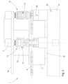
As illustrated in the merely schematic front view of FIG. 2, the
回転テーブルデジタル印刷機1にワークステーション8~18を有利に取り付けることができるように、支管33が、ステータ32から、鉛直上方向に、単に例示的には回転軸2と同軸に、延在し、リング状のワーク回転テーブル3の凹部(図示無し)を貫通する。支管33の上端部には、例示的な円形円盤状支持板34が配置され、ワークステーション8~18を各ワークキャリア4の上方に固定するのに用いられる。明瞭にするために、2つの印刷ユニット21が支持板34に配置され、この印刷ユニット21の一方が、正面図で支持板34に配置されて図示され、他方が、側面図で支持板34に配置されて図示されている。印刷ユニット21それぞれは、印刷方向28にインク液滴を供給するように設計され、その結果、インク液滴が、少なくともおおよそ鉛直方向に、各ワーク6の表面に横向きに当たる。
A
以下の説明は、各場合において、図2に図示される印刷ユニット21両方に関係する。印刷ユニット21両方は、技術的に同一に設計されるので、参照符号に違いを設ける必要はない。
The following description relates in each case to both
印刷ユニット21は、単に例示的に、左右に配置された2つの枠部35、36を有する。枠部35、36は、板状の印刷ユニットインターフェース37と共に、印刷ユニット21の支持枠38を形成し、且つ、U字状の概形を決定する。印刷ユニットインターフェース37はその上側39で印刷ユニットレセプタクル40に接続される。印刷ユニットレセプタクル40につき、以下、より詳細に記載する。
The
枠部35、36の間の中間空間内には、図3を参照してより詳細に以下に記載されるインク装置43が配置される。
枠部35、36の下端部に(図2及び図3に示す位置による)、印刷ヘッドインターフェース44が配置される。印刷ヘッドインターフェース44は、連結板45と、電動スピンドルドライブ直線駆動装置46(詳細な図示無し)と、直線駆動装置46の可動台車に固定された連結板47とを有する。直線駆動装置46により、連結板47の、回転軸2に対する横方向の直線調整、すなわち、ワーク回転テーブル3に対する径方向の直線調整が可能となる。
In the intermediate space between the
At the lower ends of
図4に図示するように、印刷ヘッドモジュール49は、板状の印刷ヘッドキャリア50と、印刷ヘッドキャリア50に固定された印刷ヘッド22、23、24とを本質的に有し、且つ、連結板47の下側48に取り付けられる。連結板47は、単に例示的に、平面である。
As shown in FIG. 4, the
例えば、印刷ヘッドキャリア50は、連結板47に対向する上側面51が平面状に形成される。その結果、上側51が下側48と面接触でき、これにより、キャリアインターフェースが形成される。印刷ヘッドキャリア50と連結板47との間に正確且つ再現可能な空間的アライメントを確保するために、2つの正確に位置決めされた芯出しピン52、53が上側51に取り付けられる。芯出しピン52、53は、上側51の上の連結板47の方向に突出し、且つ、相互に正確に同様となるように位置決めされた連結板47の挿着孔(図示無し)に係合し得る。よって、芯出しピン52、53は、キャリアインターフェースの構成要素として認識され得る。
For example, the
芯出し要素として機能する芯出しピン52、53に対する印刷ヘッド22、23、24の正確なアライメントを確保するために、印刷ヘッドキャリア50に強固に固定される印刷ヘッド22と、印刷ヘッドキャリア50上でそれぞれ直線的に変位自在に移動可能な印刷ヘッド23、24とが、測定テーブルのような高性能測定装置を使って位置合わせされ、この位置合わせが成功した後に、単に記号的に図示されている各締付ねじ54を固定する。印刷ヘッド23、24の直線的に移動可能な配置のために、各印刷ヘッド24には、電動直線アクチュエータ55が割り当てられる。
The
図3において、印刷ユニット21の上述した構成要素と、色処理モジュール56と乾燥モジュール57のような、印刷動作を実行するのに同様に必要な周辺構成要素との連続的な配置が明瞭に図示されている。
In FIG. 3, the sequential arrangement of the above-mentioned components of
印刷ユニット21の構成要素とこれら周辺構成要素のコンパクトでメンテナンスし易い配置を達成するために、これら構成要素は、印刷方向28に特に平行に配置された延長軸58に沿って連続的に配置されるが、これは、単に例示的にこれら構成要素の下向きの順序を示すものである。
In order to achieve a compact and maintenance-friendly arrangement of the components of the
これによって、特に、印刷ヘッドモジュール49や、印刷ヘッドキャリア50に取り付けられた印刷ヘッド22、23、24へのアクセスが容易である。
単に例示的に芯出しピン52、53として設計された芯出し要素と、対応し合う面(底面48と上面51)とにより、印刷ヘッドキャリア50の取り換えが簡単であり、且つ、印刷ヘッドキャリア50の位置が正確に再現可能である。更に、取り付けられた印刷ヘッド22、23、24を有する印刷ヘッドキャリア50は、比較的体積が小さいので、取替品及び取替部品の郵便による郵送が可能であり、その結果、印刷ヘッド22、23、24が蒙る問題は、世界的規模において、短期間で解決され得る。
This facilitates, among other things, access to the
The centering elements, which are designed as centering
図3において、支持板34に対する印刷ユニットレセプタクル40の設置が図示される。例えば、印刷ユニットレセプタクル40は、弾性蛇腹41によって囲まれた調整手段(図示無し)を介して保持板42に連結され、保持板42が、保持枠として機能する支持板34に接続される。印刷ユニットレセプタクル40と保持板42との間に配置される調整手段により、保持板42に対する印刷ユニットレセプタクル40の相対空間的位置の調整が可能となる。この調整手段は、特に、手動で調整可能な調整スピンドルと、電動直線駆動装置と、ワークキャリア4に対する印刷ユニットレセプタクル40とそこに収容された印刷ユニット21の正確なアライメントを可能にする電動回転駆動装置と、のグループから形成される。例えば、この調整手段(図示無し)によって、垂直方向及び水平方向に向けられた矢印と記号的な矢の後端及び矢の先端によって図示されているように、3つの互いに直交する空間的な方向における直線的な変位が可能となる。更には、例えば、この調整手段(図示無し)により、カーブした双方向矢印によって象徴されるように、互いに直交して向けられた3つの軸周りでの枢動運動が可能となる。
In FIG. 3 the installation of the
図3の模式図より、印刷ユニット21の構成要素の機械的インターフェースと周辺構成要素によって、単に例示的に、互いに平行に、且つ、一つながりの列配置に沿って、配置されたいくつかのインターフェース面80~84が決定されることが分かる。インターフェース面80~84は、ワークキャリア4により定義されるワーク面61に平行であるようにする。色処理モジュール56が、その下側により、垂直方向で一番上であり、且つ、図3には図示されていない支持板34の上側に相当する、インターフェース面80を決定する。図3には図示されていない支持板34の下側に相当するインターフェース面81は、印刷ユニットレセプタクル40の保持板42を固定するためのものである。インターフェース面82は、印刷ユニットレセプタクル40と印刷ユニット21との間の面を意味する。
From the schematic diagram of FIG. 3, several interfaces arranged parallel to each other and along a continuous row arrangement, merely by way of example, by means of the mechanical interfaces and peripheral components of the components of the
インターフェース面83は、印刷ヘッドインターフェース44と印刷ヘッドモジュール49との間の接続により決定される。乾燥モジュール57の上側が、ワーク面61の下方で、更なるインターフェース面84を形成する。ただし、インターフェース面84はその他のインターフェースレベル80~83からは逸脱し、他の構成要素との機械的接続は意味しない。インターフェース面84は、乾燥モジュール57によって供給される、特に紫外線など、電磁波の出射面を意味する。
図3の代表図からも分かるように、インク処理モジュール56は、色リザーバ60からインクを運び出すように設計されたポンプ59を有する。色リザーバ60は、単に例示的に、ワークキャリア4によって定義され、且つ、回転軸2に垂直に向けられたワーク面61の鉛直方向下方に配置される。ポンプ59によってくみ出される印刷インクは、沈静化タンク62の中で最初に貯蔵され、その後に、色管75の中のもう一つのポンプ63によって沈静化タンク62からくみ出される。例示的に、脱気装置65と、フィルタ装置66と、温度制御装置67との一連の回路が、色管75に備えられ、これらにより、印刷ユニット21で使用する印刷インクが調節される。
As can also be seen from the representative view of FIG. 3, the
色管75は、インク装置43内に配置されたバルブ装置68に接続される。バルブ装置68は、例えば比例弁として形成され、且つ、インク装置43の中に統合された制御装置69に電気的に接続される。制御装置69は、供給管70を介して印刷ヘッドモジュール49にインクを常に正しく供給できるようにバルブ装置68を駆動するように、構成される。供給管70は、印刷ヘッド22、23、24それぞれに印刷インクを供給するために、印刷ヘッドモジュール49内で分岐する。供給管70は、図4に詳細に図示される。図4に図示されるように、印刷ヘッド22、23、24それぞれは、共通の制御線71を介して制御装置69に接続される。この制御線71は図3には図示されていないが、図4にてより詳細に図示される。
The
制御装置69は、直線駆動装置46を駆動するためにも設けられる。直線駆動装置46により提供され、且つ、径方向に並ぶ直線的な移動は、ワークキャリア4の回転移動とワークキャリア4上に受け取られるワーク6の回転移動と重畳されてもよい。これにより、ワーク6上で、印刷ヘッド22、23、24から分注されるインク液滴による螺旋状の印刷経路が実現される。この目的のために、制御線72が、制御装置69と直線駆動装置46との間で形成される。制御線72により、印刷ヘッド22に対する印刷ヘッド23、24の相対移動用の直線アクチュエータ55の制御も実施される。
A
ワーク面61の下方で、乾燥モジュール57が、ワークキャリア4それぞれに配置され、単に例示的に、洗浄モジュール73と組み合わされる。乾燥モジュール57と洗浄モジュール73とは、アクチュエータ74(記号でだけ図示)の助けにより、マシンベッド31上で直線状に移動可能に配置される。また、洗浄モジュール73が印刷ヘッド22、23、24に直接対向するように位置決めされるように、洗浄モジュール73の高さ調整が行われ得る。
Below the
乾燥モジュール57は、例えば、詳細に図示されていないが、紫外線照射用に設計された短冊状に配置された光源、特にLEDを有する。これら光源は、各ワークキャリア4の回転軸に平行に延在される。よって、光源から供給される光ビームは、ワークが回転軸周りで回転している間、ワークの外面全体を照らすことができ、その結果、例えば、印刷ユニットによりワーク6に付与されたインクを硬化することができる。好ましくは、各乾燥モジュール57は、乾燥又は硬化工程を実施するために、各ワークキャリア4の鉛直方向下側に配置され得る。各乾燥モジュール57は、ワークキャリア4に対する図3に図示された位置をとる。
The drying
例えば、乾燥モジュール57は、洗浄モジュール73と共に集合体を形成し、アクチュエータ74の助けにより、図3に示す乾燥位置から洗浄位置(図示無し)に移動され得る。これを行うために、ワーク回転テーブルは、ステップ幅W/2の動きを実施し、ワークキャリア4が、印刷ヘッド22、23、24に対向して配置されないようにする。その後、洗浄モジュールが、アクチュエータ74の水平及び垂直移動の組み合わせにより、印刷ヘッドモジュールに直接対向して配置され、印刷ヘッド22、23、24の洗浄工程が開始され得る。これを行うために、洗浄モジュール73は、洗浄サイクル実施中に、印刷ヘッド22、23、24から出力される大量のカラー、特にインク、を受けることができる吸収材(図示無し)を具備する。好ましくは、この洗浄サイクルの間、印刷ヘッド22、23、24のすべてのノズルが、インク供給用に駆動され、それにより、任意で再確立される。
For example, drying
Claims (15)
ワーク回転テーブル(3)が回転軸(2)を中心に回転可能に取り付けられる装置枠(30)を有し、
前記ワーク回転テーブル(3)は、同一の角度ピッチで且つ前記回転軸(2)から同一の距離で全て配置される複数のワークキャリア(4)を備え、
駆動装置は、回転ステップ移動を実現するために前記ワーク回転テーブル(3)に割り当てられ、
前記装置枠(30)は、ワーク(6)の加工用に構成されたワークステーション(8~18)を受けるように設計された少なくとも1つの保持枠(34)を有し、
前記ワークステーション(8~18)のうち少なくとも1つは、前記保持枠(34)に取り付けられ、且つ、ワーク(6)に印刷するための印刷ユニット(21)として設計され、
前記印刷ユニット(21)は、インク装置(43)と印刷ヘッドモジュール(49)とを受けるように設計され、且つ、前記保持枠(34)と関連する印刷ユニットレセプタクル(40)と連結するように設計される印刷ユニットインターフェース(37)を有する、支持枠(38)を有し、
前記支持枠(38)は、印刷ヘッドモジュール(49)に連結するように構成される印刷ヘッドインターフェース(44)を有し、
ワーク(6)上に、インク液滴を印刷方向(28)に分注するように構成され、且つ、印刷ヘッドキャリア(50)と前記印刷ヘッドキャリア(50)に固定される少なくとも1つの印刷ヘッド(22、23、24)とを有するように構成される、印刷ヘッドモジュール(49)を更に有し、
前記印刷ヘッドモジュール(49)にインクを供給するように構成されるインク装置(43)を更に有し、
前記印刷ヘッドキャリア(50)は、前記印刷ヘッドインターフェース(44)に連結するように構成されたキャリアインターフェース(51、52、53)を有し、
前記印刷ユニットレセプタクル(40)と、前記印刷ユニットインターフェース(37)と、前記インク装置(43)と、前記印刷ヘッドインターフェース(44)と、前記キャリアインターフェース(51、52、53)と、前記印刷ヘッドモジュール(49)とは、前記印刷方向(28)に沿って延在する列配置で配置される、
回転テーブルデジタル印刷機。 A rotary table digital printing press for printing on a workpiece (6) in an inkjet digital printing method, comprising:
A workpiece rotary table (3) has a device frame (30) rotatably mounted around a rotary shaft (2),
The workpiece rotary table (3) comprises a plurality of workpiece carriers (4) all arranged at the same angular pitch and at the same distance from the rotary shaft (2),
a drive device is assigned to said workpiece rotary table (3) for realizing a rotary step movement;
said equipment frame (30) has at least one holding frame (34) designed to receive work stations (8-18) configured for processing workpieces (6);
at least one of said workstations (8-18) is mounted on said holding frame (34) and is designed as a printing unit (21) for printing on workpieces (6),
Said printing unit (21) is designed to receive an inking device (43) and a printhead module (49), and to interface with a printing unit receptacle (40) associated with said holding frame (34). having a support frame (38) with a designed printing unit interface (37);
said support frame (38) having a printhead interface (44) configured to couple to a printhead module (49);
A printhead carrier (50) and at least one printhead fixed to said printhead carrier (50) and configured to dispense ink droplets onto a workpiece (6) in a printing direction ( 28 ). (22, 23, 24), further comprising a printhead module (49) configured to have (22, 23, 24);
further comprising an inking device (43) configured to supply ink to the printhead module (49);
said printhead carrier (50) having carrier interfaces (51, 52, 53) configured to couple to said printhead interface (44);
said printing unit receptacle (40), said printing unit interface (37), said inking device (43), said printing head interface (44), said carrier interfaces (51, 52, 53) and said printing head the modules (49) are arranged in a row arrangement extending along said printing direction (28);
Rotary table digital printing press.
請求項1に記載の回転テーブルデジタル印刷機。 Said carrier interfaces (51, 52, 53 ) are two cores designed to replicate the positioning of said printhead carrier (50) with respect to said printhead interface (44) on said support frame (38). having extension elements (52, 53),
2. The rotary table digital printing press of claim 1.
請求項2に記載の回転テーブルデジタル印刷機。 At least one said printhead (22, 23, 24) is arranged in a predeterminable arrangement with respect to at least two said centering elements (52, 53) formed on said printhead carrier (50). ,
3. A rotary table digital printing machine according to claim 2.
少なくとも2つの前記芯出し要素(52、53)は、前記キャリアインターフェース(51、52、53)の前記平面(51)上に配置される、
請求項2又は請求項3に記載の回転テーブルデジタル印刷機。 each of said carrier interfaces (51, 52, 53) and said printhead interface (44) has a plane (48, 51) oriented perpendicular to said printing direction (28);
at least two of said centering elements (52, 53) are arranged on said plane (51) of said carrier interface (51, 52, 53) ;
4. The rotary table digital printing press according to claim 2 or 3.
請求項1~4のうちいずれか一項に記載の回転テーブルデジタル印刷機。 The printhead interface (44) is movably mounted to the support frame (38) with at least one degree of freedom of movement , and the support frame (38) and the printhead interface (44) are movably mounted. ) with an adjustment device (46) linearly adjustable for movement between
A rotary table digital printing press according to any one of claims 1 to 4.
前記色管(75)と前記排出管(70)は、前記排出管(70)内のインク体積流量に影響を及ぼすように設計されるバルブ装置(68)に接続され、
前記制御装置(69)は、前記バルブ装置(68)及び/又は少なくとも1つの前記印刷ヘッド(22、23、24)を制御するように設計される、
請求項1~5のうちいずれか一項に記載の回転テーブルデジタル印刷機。 The inking device ( 43 ) has a control device (69), a color tube (75) for supplying ink, and a discharge tube (70) for discharging ink to the print head module (49),
said color tube (75) and said discharge tube (70) are connected to a valve device (68) designed to influence the ink volumetric flow rate in said discharge tube (70);
said control device (69) is designed to control said valve device (68) and/or at least one of said printheads (22, 23, 24),
The rotary table digital printing press according to any one of claims 1-5.
前記印刷ヘッド(22、23、24)のうち少なくとも1つは、前記印刷ヘッドキャリア(50)に対する径方向における前記印刷ヘッド(22、23、24)のそれぞれの直線変位用に設計される位置決め装置(55)を有し、
前記制御装置(69)は、前記印刷ヘッド(22、23、24)と前記位置決め装置(55)の制御用に設計される、
請求項6に記載の回転テーブルデジタル印刷機。 Said printhead module (49) comprises at least two printheads (22, 23, 24), each of said printheads (22, 23, 24) being radially arranged with a constant pitch. and having a plurality of print nozzles forming a row of nozzles, the plurality of nozzle rows of the print head being arranged parallel to each other,
at least one of said printheads (22,23,24) is a positioning device designed for linear displacement of each of said printheads (22,23,24) in radial direction with respect to said printhead carrier (50) (55),
said controller (69) is designed for control of said print heads (22, 23, 24) and said positioning device (55),
7. A rotary table digital printing press according to claim 6.
請求項1~7のうちいずれか一項に記載の回転テーブルデジタル印刷機。 At least one positioning unit affecting the spatial orientation of said printing unit interface (37) with respect to said retaining frame (34) comprises a printing unit receptacle (40) attached to said retaining frame (34) and said retaining frame. (34) and
The rotary table digital printing press according to any one of claims 1-7.
前記色処理モジュール(56)は、前記インク装置(43)へインクを供給するように設計される色管(75)に接続される、
請求項1~8のうちいずれか一項に記載の回転テーブルデジタル印刷機。 a color processing module (56) located adjacent to said print unit interface (37) is located in an end region of said row arrangement opposite said printhead module (49);
said color processing module (56) is connected to a color tube (75) designed to supply ink to said inking device (43);
The rotary table digital printing press according to any one of claims 1-8.
請求項9に記載の回転テーブルデジタル印刷機。 Said color processing module (56) comprises a pump unit (59) for conveying printing ink and/or comprises an ink reservoir (62) for temporary storage of printing ink and/or with a temperature control device (67) for controlling the temperature of the ink and/or with a degassing device (65) for degassing said printing ink and/or with a filter for filtering said printing ink having a device (66),
A rotary table digital printing press according to claim 9 .
前記乾燥モジュール(57)は、前記印刷方向(28)における前記印刷ヘッドモジュール(49)とのワーク隙間を定め、且つ、前記ワーク隙間に配置されたワーク(6)に乾燥エネルギーを供給するように設計される、
請求項1~10のうちいずれか一項に記載の回転テーブルデジタル印刷機。 drying modules (57) are arranged in said row arrangement opposite said printhead modules (49) and are arranged with respect to said device frame (30);
The drying module (57) defines a work gap with the printhead module (49) in the print direction (28) and supplies drying energy to a work (6) positioned in the work gap. designed,
The rotary table digital printing press according to any one of claims 1-10.
前記印刷ユニットインターフェース(37)と、前記インク装置(43)と、前記印刷ヘッドインターフェース(44)と、前記キャリアインターフェース(51、52、53)と、前記印刷ヘッドモジュール(49)とは、前記ワーク面(61)の鉛直方向上方に配置される、
請求項1~11のうちいずれか一項に記載の回転テーブルデジタル印刷機。 said work carrier (4) defines a work surface (61) oriented perpendicular to said axis of rotation (2) of said work turntable (3);
The printing unit interface (37), the inking device (43), the printhead interface (44), the carrier interfaces (51, 52, 53) and the printhead module (49) are connected to the work piece. located vertically above the surface (61),
A rotary table digital printing press according to any one of claims 1-11.
請求項12に記載の回転テーブルデジタル印刷機。 at least one color reservoir (60) and a washing module (73) combined with a drying module (57) are arranged in a region vertically below said work surface (61),
13. The rotary table digital printing press of claim 12.
請求項1に記載の回転テーブルデジタル印刷機。 the printing direction (28) is aligned parallel to the vertically oriented axis of rotation (2);
2. The rotary table digital printing press of claim 1.
インク装置(43)と印刷ヘッドモジュール(49)とを受けるように構成される支持枠(38)を有し、
前記支持枠(38)は、回転テーブルデジタル印刷機(1)の印刷ユニットレセプタクル(40)に連結するように構成される印刷ユニットインターフェース(37)を有し、
前記支持枠(38)は、印刷ヘッドモジュール(49)に連結するように設計される印刷ヘッドインターフェース(44)と、印刷対象(6)に対し印刷方向(28)においてインク液滴を分注するように構成され、且つ、印刷ヘッドキャリア(50)と前記印刷ヘッドキャリア(50)に固定される少なくとも1つの印刷ヘッド(22、23、24)とを有する、印刷ヘッドモジュール(49)と、前記印刷ヘッドモジュール(49)に印刷インクを供給するように構成されたインク装置(43)と、を有し、前記インク装置(43)は、インク供給用の色管(75)と、インク排出用の排出管(70)と、を有し、
前記色管(75)と前記排出管(70)は、前記排出管(70)内のインク体積流量に影響を及ぼすように設計されるバルブ装置(68)に接続され、
前記印刷ヘッドキャリア(50)は、前記印刷ヘッドインターフェース(44)に連結するように構成されるキャリアインターフェース(51、52、53)を有し、
前記印刷ユニットインターフェース(37)と、前記インク装置(43)と、前記印刷ヘッドインターフェース(44)と、前記キャリアインターフェース(51、52、53)と、前記印刷ヘッドモジュール(49)とは、前記印刷方向(28)に沿って連続的に配置される、
回転テーブルデジタル印刷機(1)で使用する印刷ユニット。 A printing unit for use in a rotary table digital printing machine (1), comprising:
a support frame (38) configured to receive an inking device (43) and a printhead module (49);
said support frame (38) has a printing unit interface (37) configured to couple to a printing unit receptacle (40) of a rotary table digital printing machine (1);
Said support frame (38) comprises a printhead interface (44) designed to connect to a printhead module (49) and to dispense ink droplets in a printing direction (28) to a printing object (6). and a printhead module (49) comprising a printhead carrier (50) and at least one printhead (22, 23, 24) secured to said printhead carrier (50); an inking device (43) configured to supply printing ink to the printhead modules (49), said inking device (43) comprising a color tube (75) for supplying ink and a color tube (75) for discharging ink; and a discharge pipe (70) of
said color tube (75) and said discharge tube (70) are connected to a valve device (68) designed to influence the ink volumetric flow rate in said discharge tube (70);
said printhead carrier (50) having carrier interfaces (51, 52 , 53) configured to couple to said printhead interface (44);
The printing unit interface (37), the inking device (43), the printhead interface (44), the carrier interfaces (51, 52, 53) and the printhead module (49) are connected to the printing arranged continuously along the direction (28);
A printing unit for use in a rotary table digital printing machine (1).
Applications Claiming Priority (2)
| Application Number | Priority Date | Filing Date | Title |
|---|---|---|---|
| EP17196877.9A EP3473446B1 (en) | 2017-10-17 | 2017-10-17 | Roundtable digital printing machine and printing unit |
| EP17196877.9 | 2017-10-17 |
Publications (3)
| Publication Number | Publication Date |
|---|---|
| JP2019093704A JP2019093704A (en) | 2019-06-20 |
| JP2019093704A5 JP2019093704A5 (en) | 2021-11-25 |
| JP7231189B2 true JP7231189B2 (en) | 2023-03-01 |
Family
ID=60138242
Family Applications (1)
| Application Number | Title | Priority Date | Filing Date |
|---|---|---|---|
| JP2018195840A Active JP7231189B2 (en) | 2017-10-17 | 2018-10-17 | Rotary table digital printer and printing unit |
Country Status (8)
| Country | Link |
|---|---|
| US (1) | US10696068B2 (en) |
| EP (1) | EP3473446B1 (en) |
| JP (1) | JP7231189B2 (en) |
| CN (1) | CN109664613B (en) |
| CA (1) | CA3020116A1 (en) |
| ES (1) | ES2823252T3 (en) |
| IL (1) | IL262436B (en) |
| TW (1) | TWI775967B (en) |
Families Citing this family (9)
| Publication number | Priority date | Publication date | Assignee | Title |
|---|---|---|---|---|
| CN110271283B (en) * | 2019-07-11 | 2020-11-27 | 浙江超鹏彩印有限公司 | Printing roller for eliminating paper scraps and powder by utilizing periodic vibration of machine body |
| JP7512591B2 (en) * | 2019-12-25 | 2024-07-09 | ブラザー工業株式会社 | Transport control device, transport control method, and computer program |
| WO2021167637A1 (en) | 2020-02-20 | 2021-08-26 | LSINC Corporation | Container decorating machine having a plurality of independent print workstations |
| IT202100007904A1 (en) * | 2021-03-30 | 2022-09-30 | Quantix Digital S R L | INKJET DIGITAL PRINTING MACHINE FOR PRINTING CYLINDRICAL MEDIA |
| US11827045B2 (en) * | 2021-04-15 | 2023-11-28 | Ds Containers, Inc. | Manufacture of aerosol containers |
| IT202100014864A1 (en) * | 2021-06-08 | 2022-12-08 | Quantix Digital S R L | PRE-TREATMENT DEVICE AND DIGITAL INKJET PRINTER INCLUDING SUCH PRE-TREATMENT DEVICE |
| EP4155082A1 (en) | 2021-09-28 | 2023-03-29 | Hinterkopf GmbH | Digital printing device, method for producing and printing a workpiece, system for providing printed workpieces |
| CN114312046A (en) * | 2021-12-10 | 2022-04-12 | 上海泰威技术发展股份有限公司 | Digital printing structure of tank body |
| DE102022100700A1 (en) | 2022-01-13 | 2023-07-13 | Kolbus Gmbh & Co. Kg | Printing device for individual printing of web-shaped or sheet-shaped printing materials |
Citations (5)
| Publication number | Priority date | Publication date | Assignee | Title |
|---|---|---|---|---|
| JP2005138013A (en) | 2003-11-05 | 2005-06-02 | Seiko Epson Corp | Control method of liquid droplet discharge device and liquid droplet discharge device |
| JP2006212978A (en) | 2005-02-04 | 2006-08-17 | Master Mind Co Ltd | Rotary printing device for printing t-shirt |
| JP2007276145A (en) | 2006-04-03 | 2007-10-25 | Mimaki Engineering Co Ltd | Printer apparatus |
| JP2016163844A (en) | 2016-06-17 | 2016-09-08 | 株式会社ソフイア | Game machine |
| JP2017056718A (en) | 2015-09-16 | 2017-03-23 | ハイデルベルガー ドルツクマシーネン アクチエンゲゼルシヤフトHeidelberger Druckmaschinen AG | Method for avoiding collisions, method for adapting spacing, and method for actuator-based lifting |
Family Cites Families (19)
| Publication number | Priority date | Publication date | Assignee | Title |
|---|---|---|---|---|
| BE1013128A6 (en) * | 1999-09-21 | 2001-10-02 | Volder L De | Device for printing objects of the type of tablets with special medical tablets. |
| EP1493671B1 (en) * | 2003-07-02 | 2006-10-25 | Khs Ag | Mobile module carrier |
| US6923115B1 (en) * | 2003-11-19 | 2005-08-02 | Ross Clayton Litscher | Method, apparatus and system for printing on textured, nonplanar objects |
| DE102006001223A1 (en) * | 2006-01-10 | 2007-07-12 | Khs Ag | Apparatus for printing on bottles or similar containers |
| CN101674940B (en) * | 2007-08-03 | 2012-01-11 | Khs有限责任公司 | Device and method for printing containers |
| DE102008012502B4 (en) * | 2008-03-04 | 2021-05-12 | Krones Aktiengesellschaft | Device for the continuous printing of containers with a curved printing surface |
| JP4720876B2 (en) * | 2008-08-28 | 2011-07-13 | ブラザー工業株式会社 | Inkjet recording device |
| DE102009033810A1 (en) * | 2009-07-18 | 2011-01-27 | Till, Volker, Dipl.-Ing. | Plant for printing on containers |
| CN201970566U (en) * | 2010-12-29 | 2011-09-14 | 深圳市通产丽星股份有限公司 | Coupling mechanism for turntable type printing machine |
| FR2985683B1 (en) * | 2012-01-16 | 2014-02-28 | Jean Luc Perret | PRINTING MACHINE ON THREE-DIMENSIONAL ARTICLES AND PRINTING METHOD |
| US9701064B2 (en) * | 2013-07-15 | 2017-07-11 | Xerox Corporation | Digital manufacturing system for printing three-dimensional objects on a rotating core |
| DE102013214980A1 (en) * | 2013-07-31 | 2015-02-05 | Krones Ag | Printing machine with printhead control |
| US9533506B2 (en) * | 2013-09-04 | 2017-01-03 | Krones Ag | Container handling machine for printing onto container |
| PL2860036T3 (en) | 2013-10-09 | 2020-08-24 | Hinterkopf Gmbh | Printing press, printing machine and method for operating a printing press |
| DE102014206730A1 (en) * | 2014-04-08 | 2015-10-08 | Krones Ag | Apparatus and method for ink jet printing on containers |
| WO2016043267A1 (en) * | 2014-09-18 | 2016-03-24 | コニカミノルタ株式会社 | Method for removing air bubbles from inkjet head and apparatus for removing air bubbles from inkjet head |
| JP6568692B2 (en) * | 2015-03-04 | 2019-08-28 | 昭和アルミニウム缶株式会社 | Printing device |
| ES2712862T3 (en) * | 2015-03-04 | 2019-05-16 | Kosme Srl Unipersonale | Labeling machine |
| US10000065B1 (en) * | 2017-06-15 | 2018-06-19 | The Boeing Company | Inkjet printing system having dynamically controlled ink reservoir |
-
2017
- 2017-10-17 EP EP17196877.9A patent/EP3473446B1/en active Active
- 2017-10-17 ES ES17196877T patent/ES2823252T3/en active Active
-
2018
- 2018-10-02 US US16/149,705 patent/US10696068B2/en active Active
- 2018-10-09 CA CA3020116A patent/CA3020116A1/en active Pending
- 2018-10-16 TW TW107136307A patent/TWI775967B/en active
- 2018-10-17 IL IL262436A patent/IL262436B/en unknown
- 2018-10-17 JP JP2018195840A patent/JP7231189B2/en active Active
- 2018-10-17 CN CN201811208564.9A patent/CN109664613B/en active Active
Patent Citations (5)
| Publication number | Priority date | Publication date | Assignee | Title |
|---|---|---|---|---|
| JP2005138013A (en) | 2003-11-05 | 2005-06-02 | Seiko Epson Corp | Control method of liquid droplet discharge device and liquid droplet discharge device |
| JP2006212978A (en) | 2005-02-04 | 2006-08-17 | Master Mind Co Ltd | Rotary printing device for printing t-shirt |
| JP2007276145A (en) | 2006-04-03 | 2007-10-25 | Mimaki Engineering Co Ltd | Printer apparatus |
| JP2017056718A (en) | 2015-09-16 | 2017-03-23 | ハイデルベルガー ドルツクマシーネン アクチエンゲゼルシヤフトHeidelberger Druckmaschinen AG | Method for avoiding collisions, method for adapting spacing, and method for actuator-based lifting |
| JP2016163844A (en) | 2016-06-17 | 2016-09-08 | 株式会社ソフイア | Game machine |
Also Published As
| Publication number | Publication date |
|---|---|
| US10696068B2 (en) | 2020-06-30 |
| JP2019093704A (en) | 2019-06-20 |
| IL262436B (en) | 2022-04-01 |
| CN109664613A (en) | 2019-04-23 |
| EP3473446B1 (en) | 2020-08-26 |
| ES2823252T3 (en) | 2021-05-06 |
| CA3020116A1 (en) | 2019-04-17 |
| US20190111709A1 (en) | 2019-04-18 |
| CN109664613B (en) | 2022-07-22 |
| TWI775967B (en) | 2022-09-01 |
| EP3473446A1 (en) | 2019-04-24 |
| TW201922519A (en) | 2019-06-16 |
| IL262436A (en) | 2019-03-31 |
Similar Documents
| Publication | Publication Date | Title |
|---|---|---|
| JP7231189B2 (en) | Rotary table digital printer and printing unit | |
| US20220080654A1 (en) | Print device | |
| JP5073501B2 (en) | How to print digital images on plastic containers | |
| ES2768283T3 (en) | Printing equipment, printing machine and procedure for the operation of a printing equipment | |
| US20200171852A1 (en) | Printing system and method | |
| CN104339878B (en) | Printing machine with print head control | |
| US20180264845A1 (en) | Direct printing machine and method for printing containers using direct printing | |
| JP6747831B2 (en) | Object surface printing device | |
| JP2019093704A5 (en) | ||
| WO2014140192A2 (en) | Methods and devices for jetting viscous medium on workpieces | |
| US10933626B1 (en) | Method of decorating a container using a decorating machine having a plurality of independently controlled print workstations | |
| US10946639B1 (en) | Container decorating machine having a plurality of independent print workstations | |
| IL116630A (en) | Method and apparatus for the production of a printing stencil | |
| CN117425570A (en) | Pretreatment device and inkjet digital printer comprising the same | |
| CN109624514B (en) | Machine for printing a plurality of objects | |
| US20190270299A1 (en) | Printing machine for printing objects and corresponding method | |
| CN117255748A (en) | Ink-jet digital printer | |
| JP2018183995A (en) | Assembling device for printing head | |
| JPH03248843A (en) | Method and apparatus for printing on peripheral surface of cylindrical body |
Legal Events
| Date | Code | Title | Description |
|---|---|---|---|
| A521 | Request for written amendment filed |
Free format text: JAPANESE INTERMEDIATE CODE: A523 Effective date: 20211013 |
|
| A621 | Written request for application examination |
Free format text: JAPANESE INTERMEDIATE CODE: A621 Effective date: 20211013 |
|
| A977 | Report on retrieval |
Free format text: JAPANESE INTERMEDIATE CODE: A971007 Effective date: 20220914 |
|
| A131 | Notification of reasons for refusal |
Free format text: JAPANESE INTERMEDIATE CODE: A131 Effective date: 20221004 |
|
| A521 | Request for written amendment filed |
Free format text: JAPANESE INTERMEDIATE CODE: A523 Effective date: 20221223 |
|
| TRDD | Decision of grant or rejection written | ||
| A01 | Written decision to grant a patent or to grant a registration (utility model) |
Free format text: JAPANESE INTERMEDIATE CODE: A01 Effective date: 20230117 |
|
| A61 | First payment of annual fees (during grant procedure) |
Free format text: JAPANESE INTERMEDIATE CODE: A61 Effective date: 20230209 |
|
| R150 | Certificate of patent or registration of utility model |
Ref document number: 7231189 Country of ref document: JP Free format text: JAPANESE INTERMEDIATE CODE: R150 |