JP7220366B2 - MOTION CONTROL MECHANISM, LIQUID EJECTING PIPETTIP, MICRO-DROPLET GENERATING DEVICE AND METHOD, FLUID DRIVING MECHANISM AND FLUID DRIVING METHOD, MICRO-DROPLET GENERATING METHOD, AND SURFACE-TREATING METHOD OF LIQUID-JETTING PIPETTIP - Google Patents

MOTION CONTROL MECHANISM, LIQUID EJECTING PIPETTIP, MICRO-DROPLET GENERATING DEVICE AND METHOD, FLUID DRIVING MECHANISM AND FLUID DRIVING METHOD, MICRO-DROPLET GENERATING METHOD, AND SURFACE-TREATING METHOD OF LIQUID-JETTING PIPETTIP Download PDF

Info

Publication number
JP7220366B2
JP7220366B2 JP2020560537A JP2020560537A JP7220366B2 JP 7220366 B2 JP7220366 B2 JP 7220366B2 JP 2020560537 A JP2020560537 A JP 2020560537A JP 2020560537 A JP2020560537 A JP 2020560537A JP 7220366 B2 JP7220366 B2 JP 7220366B2
Authority
JP
Japan
Prior art keywords
liquid
pipette tip
outlet end
dispensing pipette
dispensing
Prior art date
Legal status (The legal status is an assumption and is not a legal conclusion. Google has not performed a legal analysis and makes no representation as to the accuracy of the status listed.)
Active
Application number
JP2020560537A
Other languages
Japanese (ja)
Other versions
JP2021511210A (en
Inventor
広済 盛
Current Assignee (The listed assignees may be inaccurate. Google has not performed a legal analysis and makes no representation or warranty as to the accuracy of the list.)
Sniper Beijing Medical Technologies Co Ltd
Original Assignee
Sniper Beijing Medical Technologies Co Ltd
Priority date (The priority date is an assumption and is not a legal conclusion. Google has not performed a legal analysis and makes no representation as to the accuracy of the date listed.)
Filing date
Publication date
Priority claimed from CN201810070377.2A external-priority patent/CN110066857B/en
Priority claimed from CN201810884995.0A external-priority patent/CN110805539A/en
Application filed by Sniper Beijing Medical Technologies Co Ltd filed Critical Sniper Beijing Medical Technologies Co Ltd
Publication of JP2021511210A publication Critical patent/JP2021511210A/en
Priority to JP2022162284A priority Critical patent/JP7452896B2/en
Application granted granted Critical
Publication of JP7220366B2 publication Critical patent/JP7220366B2/en
Active legal-status Critical Current
Anticipated expiration legal-status Critical

Links

Images

Classifications

    • BPERFORMING OPERATIONS; TRANSPORTING
    • B01PHYSICAL OR CHEMICAL PROCESSES OR APPARATUS IN GENERAL
    • B01LCHEMICAL OR PHYSICAL LABORATORY APPARATUS FOR GENERAL USE
    • B01L3/00Containers or dishes for laboratory use, e.g. laboratory glassware; Droppers
    • B01L3/02Burettes; Pipettes
    • B01L3/0241Drop counters; Drop formers
    • B01L3/0268Drop counters; Drop formers using pulse dispensing or spraying, eg. inkjet type, piezo actuated ejection of droplets from capillaries
    • BPERFORMING OPERATIONS; TRANSPORTING
    • B01PHYSICAL OR CHEMICAL PROCESSES OR APPARATUS IN GENERAL
    • B01LCHEMICAL OR PHYSICAL LABORATORY APPARATUS FOR GENERAL USE
    • B01L3/00Containers or dishes for laboratory use, e.g. laboratory glassware; Droppers
    • B01L3/02Burettes; Pipettes
    • B01L3/0241Drop counters; Drop formers
    • BPERFORMING OPERATIONS; TRANSPORTING
    • B01PHYSICAL OR CHEMICAL PROCESSES OR APPARATUS IN GENERAL
    • B01LCHEMICAL OR PHYSICAL LABORATORY APPARATUS FOR GENERAL USE
    • B01L3/00Containers or dishes for laboratory use, e.g. laboratory glassware; Droppers
    • B01L3/02Burettes; Pipettes
    • BPERFORMING OPERATIONS; TRANSPORTING
    • B01PHYSICAL OR CHEMICAL PROCESSES OR APPARATUS IN GENERAL
    • B01LCHEMICAL OR PHYSICAL LABORATORY APPARATUS FOR GENERAL USE
    • B01L3/00Containers or dishes for laboratory use, e.g. laboratory glassware; Droppers
    • B01L3/02Burettes; Pipettes
    • B01L3/0286Ergonomic aspects, e.g. form or arrangement of controls
    • CCHEMISTRY; METALLURGY
    • C12BIOCHEMISTRY; BEER; SPIRITS; WINE; VINEGAR; MICROBIOLOGY; ENZYMOLOGY; MUTATION OR GENETIC ENGINEERING
    • C12MAPPARATUS FOR ENZYMOLOGY OR MICROBIOLOGY; APPARATUS FOR CULTURING MICROORGANISMS FOR PRODUCING BIOMASS, FOR GROWING CELLS OR FOR OBTAINING FERMENTATION OR METABOLIC PRODUCTS, i.e. BIOREACTORS OR FERMENTERS
    • C12M1/00Apparatus for enzymology or microbiology
    • GPHYSICS
    • G01MEASURING; TESTING
    • G01NINVESTIGATING OR ANALYSING MATERIALS BY DETERMINING THEIR CHEMICAL OR PHYSICAL PROPERTIES
    • G01N35/00Automatic analysis not limited to methods or materials provided for in any single one of groups G01N1/00 - G01N33/00; Handling materials therefor
    • G01N35/10Devices for transferring samples or any liquids to, in, or from, the analysis apparatus, e.g. suction devices, injection devices
    • G01N35/1009Characterised by arrangements for controlling the aspiration or dispense of liquids
    • G01N35/1016Control of the volume dispensed or introduced
    • BPERFORMING OPERATIONS; TRANSPORTING
    • B01PHYSICAL OR CHEMICAL PROCESSES OR APPARATUS IN GENERAL
    • B01LCHEMICAL OR PHYSICAL LABORATORY APPARATUS FOR GENERAL USE
    • B01L2200/00Solutions for specific problems relating to chemical or physical laboratory apparatus
    • B01L2200/06Fluid handling related problems
    • B01L2200/0673Handling of plugs of fluid surrounded by immiscible fluid
    • BPERFORMING OPERATIONS; TRANSPORTING
    • B01PHYSICAL OR CHEMICAL PROCESSES OR APPARATUS IN GENERAL
    • B01LCHEMICAL OR PHYSICAL LABORATORY APPARATUS FOR GENERAL USE
    • B01L2300/00Additional constructional details
    • B01L2300/08Geometry, shape and general structure
    • B01L2300/0832Geometry, shape and general structure cylindrical, tube shaped
    • B01L2300/0838Capillaries
    • BPERFORMING OPERATIONS; TRANSPORTING
    • B01PHYSICAL OR CHEMICAL PROCESSES OR APPARATUS IN GENERAL
    • B01LCHEMICAL OR PHYSICAL LABORATORY APPARATUS FOR GENERAL USE
    • B01L2400/00Moving or stopping fluids
    • B01L2400/02Drop detachment mechanisms of single droplets from nozzles or pins
    • B01L2400/021Drop detachment mechanisms of single droplets from nozzles or pins non contact spotting by inertia, i.e. abrupt deceleration of the nozzle or pin
    • BPERFORMING OPERATIONS; TRANSPORTING
    • B01PHYSICAL OR CHEMICAL PROCESSES OR APPARATUS IN GENERAL
    • B01LCHEMICAL OR PHYSICAL LABORATORY APPARATUS FOR GENERAL USE
    • B01L2400/00Moving or stopping fluids
    • B01L2400/04Moving fluids with specific forces or mechanical means
    • B01L2400/0403Moving fluids with specific forces or mechanical means specific forces
    • B01L2400/0433Moving fluids with specific forces or mechanical means specific forces vibrational forces
    • BPERFORMING OPERATIONS; TRANSPORTING
    • B01PHYSICAL OR CHEMICAL PROCESSES OR APPARATUS IN GENERAL
    • B01LCHEMICAL OR PHYSICAL LABORATORY APPARATUS FOR GENERAL USE
    • B01L2400/00Moving or stopping fluids
    • B01L2400/04Moving fluids with specific forces or mechanical means
    • B01L2400/0475Moving fluids with specific forces or mechanical means specific mechanical means and fluid pressure
    • B01L2400/0478Moving fluids with specific forces or mechanical means specific mechanical means and fluid pressure pistons
    • GPHYSICS
    • G01MEASURING; TESTING
    • G01NINVESTIGATING OR ANALYSING MATERIALS BY DETERMINING THEIR CHEMICAL OR PHYSICAL PROPERTIES
    • G01N35/00Automatic analysis not limited to methods or materials provided for in any single one of groups G01N1/00 - G01N33/00; Handling materials therefor
    • G01N35/10Devices for transferring samples or any liquids to, in, or from, the analysis apparatus, e.g. suction devices, injection devices
    • G01N2035/1027General features of the devices
    • G01N2035/1034Transferring microquantities of liquid

Description

関連出願Related application

本出願は、2018年01月24日に出願された「デジタルPCR定量検出法」という第201810070377.2号、及び、2018年08月06日に出願された「流体駆動機構及び流体駆動方法」という第201810884995.0号の中国特許出願を優先権として主張し、それらのすべてをここで参照として援用する。 This application is filed on January 24, 2018 entitled "Digital PCR Quantitative Detection Method", No. 201810070377.2 and "Fluid Drive Mechanism and Fluid Drive Method" filed on August 06, 2018. Chinese Patent Application No. 201810884995.0 is claimed as priority, all of which are hereby incorporated by reference.

本出願は、微量液体の計量と分配の技術分野に関し、特に、運動制御機構、液体吐出ピペットチップ、微小液滴生成装置及び生成方法、流体駆動機構及び流体駆動方法、微小液滴生成方法並びに液体吐出ピペットチップの表面処理方法に関する。 TECHNICAL FIELD This application relates to the technical field of micro-liquid metering and dispensing, and in particular to motion control mechanisms, liquid-dispensing pipette tips, micro-droplet generating devices and methods, fluid drive mechanisms and fluid-driving methods, micro-droplet generating methods and liquid The present invention relates to a surface treatment method for a discharge pipette tip.

現在、医学臨床検査、ナノ材料製造、食料品と環境検査、及び、生化学解析などの応用分野では、微量液体に対する精密な操作が幅広く求められている。微量液体を操作するコア技術の一つは、マイクロリットルレベルの液体を、さらに、ナノリットル、ひいては、ピコリットルの体積のマイクロ反応システムに分けるということである。マイクロ反応システムの生成に係る一つの主な技術分野は、乳化された微小液滴を生成するということである。近年、例えば、膜乳化法、噴霧乳化法、マイクロ流体制御チップ法、及び、液体吐出ピペットチップ注射/噴射法などの様々な微小液滴生成の技術が文献に記載されている。そのうち、液体吐出ピペットチップ注射/噴射法は、最新の微小液滴生成技術として、微小液滴の生成及び消耗品としてのコストの削減の側面に優れた応用の見通しを持っている。 Applications such as medical laboratory testing, nanomaterials manufacturing, food and environmental testing, and biochemical analysis currently require a wide range of applications for precise manipulation of trace amounts of liquids. One of the core technologies for microfluidic manipulation is the separation of microliter-level liquids into microreactor systems of nanoliter and even picoliter volumes. One major technical area involved in producing microreaction systems is producing emulsified microdroplets. In recent years, various microdroplet generation techniques have been described in the literature, such as membrane emulsification, spray emulsification, microfluidic control tip, and liquid ejection pipette tip injection/jetting. Among them, the liquid-dispensing pipette tip injection/jetting method, as the latest micro-droplet generation technology, has excellent application prospects in terms of generation of micro-droplets and cost reduction of consumables.

従来の液体吐出ピペットチップは、一般的に、直管状である。液体吐出ピペットチップは、その自体の延在方向における出口端と近い一方端に急速に運動するとき、生成された微小液滴を破壊してしまうことがある。生成された微小液滴の完全性を維持させるために、液体吐出ピペットチップに振動周波数を低下させることが必要となり、その結果、微小液滴を生成する速度が低下することになる。液体吐出ピペットチップ注射/噴射法を利用する場合に、液体吐出ピペットチップの出口端は、運動制御機構の連動により、油相組成物との間に対向運動が生じる。従来の運動制御機構は、利用される際に、液体吐出ピペットチップの出口端と油相組成物との対向運動を精細に制御できず、生成された微小液滴の体積の均一性が乏しい。微小液滴を生成する工程では、液体吐出ピペットチップの出口端が運動中の状態にあることから、排出液体の流速が不安定で、かつ、制御不可能になる。生成された微小液滴は、その体積にランダム性が現れている。従来の液体吐出ピペットチップ注射/噴射法では、微小液滴を生成するように、液体吐出ピペットチップに液面の上下でせん断運動させることが必要となる。しかしながら、この方法によれば、不安定な定常波が形成され、微小液滴の生成工程が不安定となってしまうおそれがある。液体吐出ピペットチップの表面特性は、微小液滴の生成に影響を与える重要な要素である。従来の液体吐出ピペットチップの断面寸法は、一般的に、ミクロンレベルである。そして、従来の表面処理方法は、寸法の比較的大きい部品に用いられるが、寸法の比較的小さい液体吐出ピペットチップに完全に適用され難い。 Conventional liquid dispensing pipette tips are generally straight tubular. A liquid-dispensing pipette tip can break up the microdroplets that are produced when it moves rapidly to one end of its extension near the exit end. In order to maintain the integrity of the generated microdroplets, it is necessary to lower the vibration frequency of the liquid dispensing pipette tip, resulting in a slower rate of microdroplet generation. When the liquid-dispensing pipette tip injection/jetting method is used, the outlet end of the liquid-dispensing pipette tip undergoes opposing motion with the oil phase composition due to the interlocking of the motion control mechanism. Conventional motion control mechanisms, when utilized, fail to finely control the opposing motion of the outlet end of the liquid dispensing pipette tip and the oil phase composition, resulting in poor volume uniformity of the generated microdroplets. In the process of generating micro-droplets, the exit end of the liquid-dispensing pipette tip is in motion, resulting in an unstable and uncontrollable flow rate of the ejected liquid. The generated microdroplets exhibit randomness in their volume. Conventional liquid dispensing pipette tip injection/ejection methods require that the liquid dispensing pipette tip undergo a shearing motion above and below the liquid surface to produce microdroplets. However, according to this method, an unstable standing wave is formed, which may destabilize the microdroplet generation process. The surface properties of the liquid ejection pipette tip are important factors affecting the generation of microdroplets. Cross-sectional dimensions of conventional liquid-dispensing pipette tips are typically on the order of microns. Conventional surface treatment methods are used for relatively large-sized parts, but are not completely applicable to relatively small-sized liquid-dispensing pipette tips.

このことに鑑み、本出願が提供する液体吐出ピペットチップは、微小液滴を生成するための液体吐出ピペットチップであって、中空のキャビティを有する針軸及び前記針軸の一方端に配置される出口端を含み、前記液体吐出ピペットチップの出口端の端面の法線と前記針軸の延在方向との夾角は90°以下である。 In view of this, the liquid-dispensing pipette tip provided by the present application is a liquid-dispensing pipette tip for generating microdroplets, which includes a needle shaft having a hollow cavity and one end of the needle shaft. Including the outlet end, the included angle between the normal line of the end surface of the outlet end of the liquid-discharging pipette tip and the extending direction of the needle shaft is 90° or less.

微小液滴生成装置は、流体駆動機構、運動制御機構及び上記態様に記載の液体吐出ピペットチップを含み、前記液体吐出ピペットチップは、出口端及び入口端を有し、その内部に第一の液体が貯留されており、前記流体駆動機構は、前記液体吐出ピペットチップの入口端に接続され、前記液体吐出ピペットチップの内部に貯留されている第一の液体を前記液体吐出ピペットチップの出口端から排出するために用いられ、前記運動制御機構は、前記液体吐出ピペットチップの出口端から排出された第一の液体が表面張力及び付着力に打ち勝ち、第二の液体内に微小液滴を形成するように、前記液体吐出ピペットチップの出口端が第二の液体の液面下に所定軌跡、所定速度又は所定加速度に従って運動するように制御するために用いられる。 A microdroplet generating device includes a fluid drive mechanism, a motion control mechanism, and a liquid-dispensing pipette tip according to the above aspect, the liquid-dispensing pipette tip having an outlet end and an inlet end and containing a first liquid therein. is stored, and the fluid driving mechanism is connected to the inlet end of the liquid-dispensing pipette tip, and drives the first liquid stored inside the liquid-dispensing pipette tip from the outlet end of the liquid-dispensing pipette tip. wherein the motion control mechanism causes the first liquid ejected from the outlet end of the liquid dispensing pipette tip to overcome surface tension and adhesion forces to form microdroplets in the second liquid. As such, it is used to control the outlet end of the liquid-dispensing pipette tip to move under the surface of the second liquid according to a predetermined trajectory, a predetermined speed, or a predetermined acceleration.

微小液滴生成方法は、上記態様のいずれか一つに記載の第一の液体を貯留している液体吐出ピペットチップを使用する微小液滴生成方法であって、第二の液体を貯留している微小液滴容器を提供し、第一の液体を前記液体吐出ピペットチップの出口端から均一な速度で排出するように制御すると、前記液体吐出ピペットチップの出口端が第二の液体の液面下に前記針軸の延在方向に沿って、変化する方形波状の速度で周期的に運動するように制御し、前記液体吐出ピペットチップの出口端が周期的に運動している周期の前半及び後半において、前記液体吐出ピペットチップの出口端の速度は、大きさが同じであり方向が反対であり、第一の液体と第二の液体とは、互いに非相溶性を持ち、又は、界面反応を有する任意の二つの液体とされる。 A microdroplet generating method is a microdroplet generating method using the liquid ejection pipette tip storing the first liquid according to any one of the above aspects, wherein the second liquid is stored and controlling the discharge of the first liquid from the outlet end of the liquid-dispensing pipette tip at a uniform speed, the outlet end of the liquid-dispensing pipette tip is above the liquid level of the second liquid. The outlet end of the liquid-dispensing pipette tip is controlled to periodically move downward along the extending direction of the needle shaft at a varying square wave-like speed, and the first half of the cycle and the In the second half, the velocities at the exit end of the liquid-dispensing pipette tip are the same in magnitude and opposite in direction, and the first liquid and the second liquid are incompatible with each other or interfacial reaction Let any two liquids with

微小液滴生成方法は、上記態様のいずれか一つに記載の第一の液体を貯留している液体吐出ピペットチップを使用する微小液滴生成方法であって、第二の液体を貯留している微小液滴容器を提供し、第一の液体を前記液体吐出ピペットチップの出口端から均一な速度で排出するように制御すると、前記液体吐出ピペットチップの出口端が第二の液体の内部に前記針軸の延在方向に沿って正弦波状の変位で周期的に運動するように制御し、第一の液体と第二の液体とは、互いに非相溶性を持ち、又は、界面反応を有する任意の二つの液体とされる。 A microdroplet generating method is a microdroplet generating method using the liquid ejection pipette tip storing the first liquid according to any one of the above aspects, wherein the second liquid is stored and controlling the discharge of the first liquid from the outlet end of the liquid-dispensing pipette tip at a uniform speed, the outlet end of the liquid-dispensing pipette tip being inside the second liquid. The first liquid and the second liquid are incompatible with each other or have interfacial reaction. Any two liquids.

上記液体吐出ピペットチップによれば、液体吐出ピペットチップが管路本体の延在方向に沿って振動すると、微小液滴は、液体吐出ピペットチップの出口端から落下した後に、第二の液体の粘性力及び液体吐出ピペットチップの出口端の端面の押圧の作用により、出口端による運動軌跡から離れたため、出口端に破壊されてしまうことが避けられており、生成された微小液滴の完全性を維持させると共に、液体吐出ピペットチップが管路本体の延在方向に沿って急速に振動して微小液滴を急速に生成することが可能となる。 According to the above-described liquid-discharging pipette tip, when the liquid-discharging pipette tip vibrates along the extension direction of the conduit body, the minute droplets fall from the outlet end of the liquid-discharging pipette tip, and then the viscosity of the second liquid increases. Due to the action of the force and the pressing of the end face of the outlet end of the liquid-dispensing pipette tip, it is separated from the trajectory of motion by the outlet end, thus avoiding being broken by the outlet end and ensuring the integrity of the generated microdroplets. In addition, the liquid discharge pipette tip can be rapidly vibrated along the extension direction of the conduit body to rapidly generate microdroplets.

このことに鑑み、本出願は、支持フレーム、接続手段及び駆動素子を含む運動制御機構を提供する。接続手段は、液体吐出ピペットチップに接続されるために用いられる。駆動素子は、前記支持フレームに固定され、前記接続手段に動力伝達可能に接続される。液体吐出ピペットチップの出口端は、前記駆動素子の駆動により、正弦波状に変位する速度、又は、方形波状に変化する速度で運動する。上記運動制御機構は、液体吐出ピペットチップの出口端が正弦波状に変位する速度又は方形波状に変化する速度で運動して微小液滴を生成するように連動することから、微小液滴の生成に効率が高く、さらに、均一性が高いという利点を持っている。 In view of this, the present application provides a motion control mechanism including a support frame, connecting means and drive elements. A connecting means is used to be connected to a liquid dispensing pipette tip. A drive element is fixed to the support frame and is power-transmittably connected to the connection means. The outlet end of the liquid-dispensing pipette tip moves at a speed that changes in a sinusoidal wave shape or a speed that changes in a square wave shape by driving the drive element. The motion control mechanism is interlocked so that the outlet end of the liquid-discharging pipette tip moves at a speed at which the liquid-discharging pipette tip is displaced in a sine wave or at a speed at which it changes in a square wave to generate minute droplets. It has the advantages of high efficiency and high uniformity.

このことに鑑み、本出願は、微小液滴生成システムに用いられており、容積可変アセンブリ及びパワーアセンブリを含む流体駆動機構を提供する。容積可変アセンブリは、駆動液体を貯留可能なシリンジ及び前記シリンジの内壁と摺動可能に協働するブッシュロッドを含み、前記シリンジは、第一の液体を貯留している液体吐出ピペットチップの入口端と連通するための液体出入口を有する。パワーアセンブリは、前記ブッシュロッドに動力伝達可能に接続され、前記ブッシュロッドが前記シリンジの延在方向に沿って摺動するように駆動するために用いられる。微小液滴を生成する工程では、前記パワーアセンブリは、前記ブッシュロッドが前記シリンジに貯留されている駆動液体を押圧するように駆動し、駆動液体は、液体吐出ピペットチップに貯留されている第一の液体を押圧することにより、第一の液体を液体吐出ピペットチップの出口端から排出する。 In view of this, the present application provides a fluid drive mechanism for use in a microdroplet generation system, including a variable volume assembly and a power assembly. The variable volume assembly includes a syringe capable of storing a drive liquid and a bushing rod slidably cooperating with an inner wall of said syringe, said syringe being positioned at the inlet end of a liquid dispensing pipette tip containing a first liquid. It has a liquid port for communicating with. A power assembly is power-transmittably connected to the bush rod and used to drive the bush rod to slide along the extending direction of the syringe. In the step of generating microdroplets, the power assembly drives the bush rod to press the driving liquid stored in the syringe, and the driving liquid is the first fluid stored in the liquid ejection pipette tip. The first liquid is expelled from the outlet end of the liquid dispensing pipette tip by pressing the first liquid.

流体駆動方法は、上記態様のいずれか一つに記載の流体駆動機構を用いた流体駆動方法であって、前記パワーアセンブリは、前記ブッシュロッドが前記シリンジに貯留されている前記駆動液体を押圧するように駆動し、前記駆動液体は、前記液体吐出ピペットチップに貯留されている前記第一の液体を押圧することにより、前記第一の液体を前記液体吐出ピペットチップの出口端から排出する。 A fluid driving method is a fluid driving method using the fluid driving mechanism according to any one of the above aspects, wherein the power assembly presses the driving liquid stored in the syringe with the bush rod. The driving liquid presses the first liquid stored in the liquid-discharging pipette tip, thereby discharging the first liquid from the outlet end of the liquid-discharging pipette tip.

上記態様に記載の流体駆動機構を使用する流体駆動方法は、前記三方切替弁を介して、前記容積可変アセンブリの前記液体出入口を前記貯液タンクに連通し、前記パワーアセンブリの連動により、前記ブッシュロッドに前記シリンジ内を摺動させ、前記シリンジの容積を変更し前記貯液タンク内の前記駆動液体を前記シリンジに吸入すること、前記三方切替弁を介して、前記容積可変アセンブリの前記液体出入口を前記液体吐出ピペットチップの入口端に連通し、前記パワーアセンブリの連動により、前記ブッシュロッドに前記シリンジ内を摺動させ、前記シリンジの容積を変更し前記シリンジ内及び前記液体吐出ピペットチップ内の気体を排出すること、前記液体吐出ピペットチップの出口端を前記第一の液体に進入すると共に、前記三方切替弁を介して前記容積可変アセンブリの前記液体出入口を前記液体吐出ピペットチップの入口端に連通することを維持し、前記パワーアセンブリの連動により、前記ブッシュロッドに前記シリンジ内を摺動させ、前記シリンジの容積を変更し前記第一の液体を前記液体吐出ピペットチップに吸入すること、前記三方切替弁を介して、前記容積可変アセンブリの前記液体出入口を前記液体吐出ピペットチップの入口端に連通し、前記パワーアセンブリの連動により、前記ブッシュロッドに前記シリンジ内を摺動させ、前記シリンジの容積を変更し前記液体吐出ピペットチップに貯留されている前記第一の液体を均一な流速で前記液体吐出ピペットチップの出口端から排出することを含む。 The fluid drive method using the fluid drive mechanism according to the above aspect communicates the liquid inlet/outlet of the variable volume assembly with the liquid storage tank via the three-way switching valve, and the power assembly interlocks to operate the bush sliding a rod inside the syringe to change the volume of the syringe to suck the driving liquid in the liquid storage tank into the syringe; is connected to the inlet end of the liquid-dispensing pipette tip, and the bush rod is slid in the syringe by interlocking with the power assembly to change the volume of the syringe, thereby changing the volume of the syringe and the liquid-dispensing pipette tip. expelling the gas from the outlet end of the liquid-dispensing pipette tip into the first liquid, and through the three-way switching valve, the liquid inlet/outlet of the variable volume assembly to the inlet end of the liquid-dispensing pipette tip; maintaining communication and interlocking the power assembly to cause the bush rod to slide within the syringe to change the volume of the syringe and aspirate the first liquid into the liquid dispensing pipette tip; Via a three-way switching valve, the liquid inlet/outlet of the variable volume assembly is communicated with the inlet end of the liquid-discharging pipette tip, and the power assembly is interlocked to cause the bush rod to slide in the syringe, thereby displacing the syringe. Varying the volume and discharging the first liquid stored in the liquid-dispensing pipette tip at a uniform flow rate from the outlet end of the liquid-dispensing pipette tip.

上記流体駆動機構及び流体駆動方法によれば、駆動液体の非圧縮性を利用して、液体吐出ピペットチップの出口端が高周波数で振動しているときでも、依然として、所定流速で第一の液体を液体吐出ピペットチップの出口端から排出することを確保することができる。本出願が提供する流体駆動機構は、生成された微小液滴の体積を正確に制御することができる。 According to the fluid driving mechanism and the fluid driving method, the incompressibility of the driving liquid is used to maintain the first liquid at a predetermined flow rate even when the outlet end of the liquid-discharging pipette tip vibrates at a high frequency. is expelled from the exit end of the liquid dispensing pipette tip. The fluid drive mechanism provided by the present application can precisely control the volume of microdroplets generated.

このことに鑑み、本出願が提供する微小液滴生成方法は、出口端を有し、第一の液体を貯留している液体吐出ピペットチップを提供し、開口を有し、第二の液体を貯留している微小液滴容器を提供し、第一の液体と第二の液体とは、互いに非相溶性を持ち、又は、界面反応を有する任意の2つの液体とされるステップS201と、前記液体吐出ピペットチップの出口端を、前記微小液滴容器の開口から第二の液体の液面下に挿入するステップS202と、前記液体吐出ピペットチップの出口端に、第二の液体の液面下に瞬間加速度運動を含む運動を行わせながら、第一の液体を前記液体吐出ピペットチップの出口端から排出し、前記液体吐出ピペットチップの出口端から排出された第一の液体は、前記液体吐出ピペットチップの出口端に付着される液滴を形成し、液滴は、前記液体吐出ピペットチップの出口端が瞬間加速度運動を行っている工程において、前記液体吐出ピペットチップの出口端から脱離され、第二の液体の液面下に微小液滴を形成するステップS203と、を含む。 In view of this, the microdroplet generation method provided by the present application provides a liquid ejection pipette tip having an outlet end and storing a first liquid, and having an opening for dispensing a second liquid. step S201 of providing a reservoir of microdroplets, wherein the first liquid and the second liquid are any two liquids that are immiscible with each other or have an interfacial reaction; step S202 of inserting the outlet end of the liquid-discharging pipette tip from the opening of the microdroplet container below the surface of the second liquid; The first liquid is ejected from the outlet end of the liquid-dispensing pipette tip while performing a motion including an instantaneous acceleration motion, and the first liquid ejected from the outlet end of the liquid-dispensing pipette tip is used for the liquid ejection. Forming a droplet attached to the outlet end of the pipette tip, the droplet is detached from the outlet end of the liquid-dispensing pipette tip in a step in which the outlet end of the liquid-dispensing pipette tip undergoes a momentary acceleration motion. , and step S203 of forming microdroplets below the surface of the second liquid.

上記微小液滴生成方法は、前記液体吐出ピペットチップの出口端が瞬間加速度運動を行うと、加速度の値が比較的大きい。前記液体吐出ピペットチップの出口端に付着される液滴と前記液体吐出ピペットチップの出口端との付着力は、液滴と前記液体吐出ピペットチップの出口端とを同期に加速度運動させるために十分でないことから、前記液体吐出ピペットチップの出口端に付着された液滴は、前記液体吐出ピペットチップの出口端から脱離され、第二の液体の液面下に微小液滴を形成する。 In the microdroplet generating method, when the exit end of the liquid-dispensing pipette tip performs an instantaneous acceleration motion, the acceleration value is relatively large. The adhesive force between the droplet attached to the outlet end of the liquid-discharging pipette tip and the outlet end of the liquid-discharging pipette tip is sufficient to cause the droplet and the outlet end of the liquid-discharging pipette tip to accelerate in synchronism. Therefore, droplets attached to the outlet end of the liquid-discharging pipette tip are detached from the outlet end of the liquid-discharging pipette tip to form minute droplets below the surface of the second liquid.

本出願が提供する微小液滴生成方法は、前記液体吐出ピペットチップの出口端が第二の液体の液面下に瞬間加速度運動を含む運動を行って微小液滴を形成することから、前記液体吐出ピペットチップの出口端が運動している時に第二の液体に与えた干渉を低下させ、微小液滴を生成する工程に安定性を確保することができる。 In the microdroplet generation method provided by the present application, the outlet end of the liquid-discharging pipette tip performs a movement including an instantaneous acceleration movement under the liquid surface of the second liquid to form the microdroplet. The interference given to the second liquid when the outlet end of the dispensing pipette tip is moving can be reduced to ensure stability in the process of generating microdroplets.

このことに鑑み、本出願が提供する微小液滴生成方法は、出口端を有し、第一の液体を貯留している液体吐出ピペットチップを提供し、開口を有し、第二の液体を貯留している微小液滴容器を提供し、前記第一の液体と前記第二の液体とは、互いに非相溶性を持ち、又は、界面反応を有する任意の2つの液体とされるステップS211と、前記液体吐出ピペットチップの出口端を、前記微小液滴容器の開口から、第二の液体の液面下に挿入するステップS212と、前記液体吐出ピペットチップの出口端に、第二の液体の液面下に周期的に変化する速度で運動を行わせ、速度が変化している周期の前半及び後半において、前記液体吐出ピペットチップの出口端の速度が単調変化しながら、第一の液体が前記液体吐出ピペットチップの出口端から排出され、前記液体吐出ピペットチップの出口端から排出された第一の液体により、前記液体吐出ピペットチップの出口端に付着される液滴を形成し、前記液体吐出ピペットチップの出口端が運動している工程において、液滴は、前記液体吐出ピペットチップの出口端から脱離され、第二の液体の液面下に微小液滴を形成するステップS213と、を含む。 In view of this, the microdroplet generation method provided by the present application provides a liquid ejection pipette tip having an outlet end and storing a first liquid, and having an opening for dispensing a second liquid. step S211 of providing a reservoir of microdroplets, wherein the first liquid and the second liquid are any two liquids that are immiscible with each other or have an interfacial reaction; a step S212 of inserting the outlet end of the liquid-discharging pipette tip from the opening of the microdroplet container under the surface of the second liquid; The first liquid is caused to move under the surface of the liquid at a speed that periodically changes, and the first liquid flows while the speed at the outlet end of the liquid-discharging pipette tip changes monotonically in the first half and the second half of the cycle in which the speed changes. a first liquid ejected from the outlet end of the liquid-dispensing pipette tip, forming a droplet adhering to the outlet end of the liquid-dispensing pipette tip by the first liquid ejected from the outlet end of the liquid-dispensing pipette tip; a step S213 in which droplets are detached from the outlet end of said liquid-dispensing pipette tip to form micro-droplets under the liquid surface of the second liquid, in the step in which the outlet end of the dispensing pipette tip is moving; including.

上記の微小液滴生成方法によれば、液体吐出ピペットチップの出口端が第二の液体の液面下に周期的に変化する速度で運動を行い、速度が変化している周期の前半及び後半において、液体吐出ピペットチップの出口端の速度が単調変化する。運動の工程においては、液滴に対する第二の液体の粘性力も、液体吐出ピペットチップの出口端の速度が周期的に変化するのに伴い、周期的に変化する。液体吐出ピペットチップの出口端と液滴との最大の付着力が、液滴に対する第二の液体の粘性力よりも小さい場合に、液滴が液体吐出ピペットチップの出口端と同期に運動できなくなるため、前記液体吐出ピペットチップの出口端に付着された液滴は、前記液体吐出ピペットチップの出口端から脱離され、第二の液体の液面下に微小液滴を形成する。 According to the microdroplet generation method described above, the outlet end of the liquid-discharging pipette tip moves at a speed that periodically changes below the surface of the second liquid, and the first and second halves of the cycle in which the speed changes , the velocity of the exit end of the liquid-dispensing pipette tip changes monotonically. In the course of motion, the viscous force of the second liquid on the droplet also changes periodically as the velocity of the outlet end of the liquid dispensing pipette tip changes periodically. When the maximum adhesive force between the outlet end of the liquid-dispensing pipette tip and the droplet is less than the viscous force of the second liquid on the droplet, the droplet cannot move synchronously with the outlet end of the liquid-dispensing pipette tip. Therefore, droplets attached to the outlet end of the liquid-discharging pipette tip are detached from the outlet end of the liquid-discharging pipette tip to form minute droplets below the surface of the second liquid.

本出願が提供する微小液滴生成方法によれば、前記液体吐出ピペットチップの出口端が第二の液体の液面下に周期に変化する速度で運動を行い、微小液滴を形成することから、前記液体吐出ピペットチップの出口端が運動している時に第二の液体に与えた干渉を低下させ、微小液滴を生成する工程に、安定性を確保することができる。 According to the microdroplet generation method provided by the present application, the outlet end of the liquid-discharging pipette tip is moved at a periodically changing speed under the surface of the second liquid to form microdroplets. , the interference given to the second liquid when the outlet end of the liquid-dispensing pipette tip is moving can be reduced, and the stability can be ensured in the process of generating microdroplets.

このことに鑑み、本出願が提供する液体吐出ピペットチップに表面を処理するための液体吐出ピペットチップの表面処理方法は、前記液体吐出ピペットチップにシラン化処理を行うステップS260と、ジエチルピロカーボネート水溶液により、前記液体吐出ピペットチップを処理するステップS270と、前記液体吐出ピペットチップを乾燥させるステップS280とを含む。 In view of this, the present application provides a surface treatment method for a liquid ejection pipette tip for treating the surface of the liquid ejection pipette tip. includes a step S270 of processing the liquid ejection pipette tip and a step S280 of drying the liquid ejection pipette tip.

上記液体吐出ピペットチップの表面処理方法によれば、シラン化処理により液体吐出ピペットチップの表面自由エネルギーが低下する共に、液体吐出ピペットチップの表面自由エネルギーが一定の区間内に抑制され、微小液滴の生成工程に対する液体吐出ピペットチップの表面特性の影響が低下する。 According to the method for treating the surface of a liquid-discharging pipette tip, the silanization treatment lowers the surface free energy of the liquid-discharging pipette tip, suppresses the surface free energy of the liquid-discharging pipette tip within a certain interval, and produces fine droplets. The influence of the surface properties of the liquid dispensing pipette tip on the production process of is reduced.

このことに鑑み、本出願が提供する流体駆動機構は、微小液滴生成システムに用いられており、筐体、第一の容積可変アセンブリ、及び、リニアモーターアセンブリを含む。前記第一の容積可変アセンブリは、前記筐体に配置され、第一のシリンジ及び第一のブッシュロッドを含み、前記第一のブッシュロッドは、前記第一のシリンジの内壁と摺動的に協働され、前記第一のシリンジは、第一の駆動液体を貯留可能であり、第三の液体を貯留する第一の液体吐出ピペットチップの入口端と連通するための液体出入口を有する。前記リニアモーターアセンブリは、前記筐体に配置され、その出力端が前記第一のブッシュロッドに動力伝達可能に接続され、前記第一のブッシュロッドが前記第一のシリンジの延在方向に沿って摺動するように駆動するために用いられる。 In view of this, the fluid drive mechanism provided by the present application is used in a microdroplet generation system and includes a housing, a first variable volume assembly, and a linear motor assembly. The first variable volume assembly is disposed in the housing and includes a first syringe and a first bushing rod, the first bushing rod slidingly cooperating with an inner wall of the first syringe. The first syringe is capable of storing a first driving liquid and has a liquid port for communicating with an inlet end of a first liquid-dispensing pipette tip containing a third liquid. The linear motor assembly is disposed in the housing, has an output end connected to the first bush rod so as to be able to transmit power, and the first bush rod extends along the extending direction of the first syringe. It is used for sliding drive.

前記の流体駆動機構を使用する流体駆動方法は、前記切替弁を介して、前記第一のシリンジの前記液体出入口を前記貯液タンクに連通し、前記リニアモーターアセンブリの連動により、前記第一のブッシュロッドに前記第一のシリンジ内を摺動させ前記第一のシリンジの容積を変更し、前記貯液タンク内の前記第一の駆動液体を前記第一のシリンジに吸入する。前記切替弁を介して、前記第一のシリンジの前記液体出入口を前記第一の液体吐出ピペットチップの入口端に連通し、前記リニアモーターアセンブリの連動により、前記第一のブッシュロッドに前記第一のシリンジ内を摺動させ、前記第一のシリンジの容積を変更し前記第一のシリンジ内及び前記第一の液体吐出ピペットチップ内の気体を排出する。前記第一の液体吐出ピペットチップの出口端を前記第三の液体に進入し、前記切替弁を介して前記第一のシリンジの前記液体出入口を前記第一の液体吐出ピペットチップの入口端に連通することを維持し、パワーアセンブリの連動により、前記第一のブッシュロッドに前記第一のシリンジ内を摺動させ前記第一のシリンジの容積を変更し前記第三の液体を前記第一の液体吐出ピペットチップに吸入する。前記切替弁を介して前記第一のシリンジの前記液体出入口を前記第一の液体吐出ピペットチップの入口端に連通し、前記リニアモーターアセンブリの連動により、前記第一のブッシュロッドに前記第一のシリンジ内を摺動させ前記第一のシリンジの容積を変更し前記第一の液体吐出ピペットチップに貯留されている前記第三の液体を所定流速で前記第一の液体吐出ピペットチップの出口端から排出する。 In the fluid drive method using the fluid drive mechanism, the liquid inlet/outlet of the first syringe is communicated with the liquid storage tank via the switching valve, and the linear motor assembly is interlocked to operate the first syringe. A bush rod is slid within the first syringe to change the volume of the first syringe, and the first driving liquid in the liquid storage tank is sucked into the first syringe. Through the switching valve, the liquid inlet/outlet of the first syringe is communicated with the inlet end of the first liquid-dispensing pipette tip, and the linear motor assembly is interlocked to move the first bush rod to the first syringe. to change the volume of the first syringe and discharge the gas in the first syringe and the first liquid-dispensing pipette tip. The outlet end of the first liquid-discharging pipette tip enters the third liquid, and the liquid inlet/outlet of the first syringe communicates with the inlet end of the first liquid-discharging pipette tip via the switching valve. and the engagement of the power assembly causes the first bushing rod to slide within the first syringe to change the volume of the first syringe to change the volume of the third liquid from the first liquid. Aspirate into the dispensing pipette tip. The liquid inlet/outlet of the first syringe is communicated with the inlet end of the first liquid-dispensing pipette tip via the switching valve, and the linear motor assembly is interlocked to move the first bush rod to the first syringe. The volume of the first syringe is changed by sliding the inside of the syringe, and the third liquid stored in the first liquid-discharging pipette tip is discharged at a predetermined flow rate from the outlet end of the first liquid-discharging pipette tip. Discharge.

上記流体駆動機構及び流体駆動方法によれば、第一の駆動液体の非圧縮性により、第一の液体吐出ピペットチップの出口端が高周波数で振動している時でも、依然として所定流速で第三の液体を第一の液体吐出ピペットチップの出口端から排出することを確保することができる。リニアモーターアセンブリは、比較的高い運動精度を有するだけでなく、液体の排出速度や液体の排出圧力などの実際の状況に応じて電流を調整すると、第一のブッシュロッドが所定速度で円滑に摺動し、又は、所定距離だけ摺動することを確保することができ、第三の液体を、正確に所定の流速や流量で第一の液体吐出ピペットチップの出口端から排出することを実現することができる。本出願が提供する流体駆動機構は、生成された微小液滴に体積を正確に制御することができる。 According to the above fluid drive mechanism and fluid drive method, due to the incompressibility of the first drive liquid, even when the outlet end of the first liquid-dispensing pipette tip vibrates at a high frequency, the third liquid is still discharged at a predetermined flow rate. of liquid is expelled from the outlet end of the first liquid-dispensing pipette tip. The linear motor assembly not only has a relatively high motion accuracy, but also adjusts the current according to the actual situation, such as liquid discharge speed and liquid discharge pressure, so that the first bush rod slides smoothly at a predetermined speed. It can be ensured that it moves or slides a predetermined distance, realizing that the third liquid is ejected from the outlet end of the first liquid-dispensing pipette tip at a precisely predetermined flow rate or flow rate. be able to. The fluid drive mechanism provided by the present application can precisely control the volume of the generated microdroplets.

本出願における実施例又は従来技術における態様をより明確に説明するように、以下に、実施例又は従来技術を説明するに必要な図面を簡単に説明しておく。下記の説明に係る図面は、本出願の実施例に過ぎず、創造的労働をしない前提で、提供されている図面に基づいて他の図面を取得することも当業者にとって自明である。
本出願の一実施例が提供するデジタルPCR検出器の全体的な構造の模式図である。 本出願の一実施例が提供するデジタルPCR検出器の微小液滴生成装置である。 本出願の一実施例が提供する液体吐出ピペットチップの出口端が運動しているときに力を受ける液滴の模式図である。 本出願の一実施例が提供する液体吐出ピペットチップの出口端の速度変化の模式図である。 本出願の一実施例が提供する液体吐出ピペットチップの出口端が運動している時に微小液滴を生成する工程の模式図である。 本出願の他の実施例が提供する液体吐出ピペットチップの出口端が運動している時に力を受ける液滴の模式図である。 本出願の一実施例が提供する液滴随液体吐出ピペットチップの出口端が運動している時に理想状態での粘性抵抗の変化の模式図である。 本出願の一実施例が提供する液体吐出ピペットチップの出口端が二つの運動周期に一つの微小液滴を生成する工程の模式図である。 本出願の一実施例が提供する液体吐出ピペットチップの出口端が一つの運動周期に一つの微小液滴を生成する工程の模式図である。 本出願の一実施例が提供する液体吐出ピペットチップの出口端が一つの運動周期に二つの微小液滴を生成する工程の模式図である。 本出願の一実施例が提供する液体吐出ピペットチップが揺動しているときに微小液滴を生成する工程の模式図である。 本出願の一実施例が提供する第二の液体の粘度が変化する時に微小液滴を生成する工程の模式図である。 本出願の一実施例が提供する液体吐出ピペットチップが交換されたときに微小液滴を生成する工程の模式図である。 本出願の一実施例が提供する液体吐出ピペットチップの出口端が異なる運動軌跡で微小液滴を生成する工程の模式図である。 本出願の他の実施例が提供する液体吐出ピペットチップの出口端の速度変化の模式図である。 本出願の一実施例が提供する液体吐出ピペットチップの出口端の構造の模式図である。 本出願の他の実施例が提供する液体吐出ピペットチップの出口端の構造の模式図であるである 本出願の一実施例が提供する液体吐出ピペットチップの構造の模式図である。 本出願の他の実施例が提供する液体吐出ピペットチップの構造の模式図である。 本出願の一実施例が提供する斜めカット構造の液体吐出ピペットチップが微小液滴を生成する工程の模式図である。 本出願の他の実施例が提供する斜めカット構造の液体吐出ピペットチップが微小液滴を生成する工程の模式図である。 本出願の一実施例が提供する折り曲げ構造の液体吐出ピペットチップが微小液滴を生成する工程模式図である。 本出願の他の実施例が提供する折り曲げ構造の液体吐出ピペットチップが微小液滴を生成する工程模式図である。 本出願の一実施例が提供する液体吐出ピペットチップの表面処理方法のフローチャートである。 本出願の他の実施例が提供する液体吐出ピペットチップの表面処理方法のフローチャートである。 本出願の一実施例が提供する流体制御機構が液体吐出ピペットチップに接続される模式図である。 本出願の一実施例が提供する流体制御機構の構造の模式図である。 本出願の一実施例が提供する液体吐出ピペットチップが駆動液体の駆動により微小液滴を生成する工程の模式図である。 本出願の他の実施例が提供する流体制御機構の構造の模式図である。 本出願の一実施例が提供する運動制御機構の構造の模式図である。 本出願の一実施例が提供するクローズドループ制御モーターの制御の原理図である。 本出願の一実施例が提供する圧電型運動制御機構の構造の模式図である。 本出願の一実施例が提供する電磁気-弾性手段型運動制御機構の構造の模式図である。 本出願の他の実施例が提供する電磁気-弾性手段型運動制御機構の構造の模式図である。 本出願の一実施例が提供する電磁気-軸受型運動制御機構の構造の模式図である。 本出願の他の実施例が提供する電磁気-軸受型運動制御機構の構造の模式図である。 本出願のさらに一実施例が提供する電磁気-軸受型運動制御機構の構造の模式図である。 本出願の一実施例が提供する流体駆動機構の全体的な構造の側面の模式図である。 本出願の一実施例が提供する流体駆動機構の局所的な構造の第一の側面の模式図である。 本出願の一実施例が提供する流体駆動機構の局所的な構造の正面の模式図である。 本出願の一実施例が提供する流体駆動機構の局所的な構造の背面の模式図である。 本出願の一実施例が提供する流体駆動機構の局所的な構造の第二の側面の模式図である。 本出願の一実施例が提供する流体駆動機構の組立の分解模式図である。 本出願の一実施例が提供するボイスコイルモーター、接続板及び第一の容積可変アセンブリの構造組立の分解模式図である。 本出願の一実施例が提供するボイスコイルモーターと接続板との構造の組立の分解模式図である。 本出願の一実施例が提供する一体形成されるボビンと接続板との第一の側面の模式図である。 本出願の一実施例が提供する一体形成されるボビンと接続板との第二の側面の模式図である。 本出願の一実施例が提供する切替弁の構造の側面模式図である。 本出願の一実施例が提供する切替弁の正面断面の構造の模式図である。 本出願の一実施例が提供する流体駆動方法の工程の模式図である。
In order to more clearly describe the embodiments of the present application or aspects of the prior art, the following briefly describes the drawings necessary to describe the embodiments or the prior art. The drawings according to the following description are only examples of the present application, and it is obvious for a person skilled in the art to obtain other drawings based on the provided drawings without creative labor.
1 is a schematic diagram of the overall structure of a digital PCR detector provided by an embodiment of the present application; FIG. 1 is a microdroplet generator of a digital PCR detector provided by an embodiment of the present application; FIG. 4 is a schematic diagram of a droplet undergoing force when the outlet end of a liquid dispensing pipette tip provided by an embodiment of the present application is in motion; FIG. 4 is a schematic diagram of velocity change at the exit end of a liquid dispensing pipette tip provided by an embodiment of the present application; FIG. 4 is a schematic diagram of a process of generating microdroplets when the outlet end of a liquid dispensing pipette tip is in motion provided by one embodiment of the present application; FIG. 5 is a schematic diagram of a droplet undergoing force when the outlet end of a liquid dispensing pipette tip provided by another embodiment of the present application is in motion; FIG. 5 is a schematic diagram of a change in viscous resistance in an ideal state when the outlet end of a liquid droplet ejection pipette tip provided by an embodiment of the present application is in motion; FIG. 4 is a schematic diagram of a process in which the exit end of a liquid ejection pipette tip provided by an embodiment of the present application produces one microdroplet in two motion cycles; FIG. 4 is a schematic diagram of a process in which the exit end of the liquid-dispensing pipette tip provided by an embodiment of the present application produces one microdroplet in one motion cycle; FIG. 4 is a schematic diagram of a process in which the exit end of a liquid-dispensing pipette tip provided by an embodiment of the present application produces two micro-droplets in one motion cycle; FIG. 4 is a schematic diagram of a process of generating minute droplets when a liquid-discharging pipette tip provided by an embodiment of the present application is rocking; FIG. 4 is a schematic diagram of a process of generating microdroplets when the viscosity of a second liquid changes provided by an embodiment of the present application; FIG. 4 is a schematic diagram of a process of generating microdroplets when a liquid ejection pipette tip provided by an embodiment of the present application is replaced; FIG. 4 is a schematic diagram of a process of generating microdroplets with different motion trajectories of the exit end of a liquid ejection pipette tip provided by an embodiment of the present application; FIG. 4 is a schematic diagram of velocity change at the exit end of a liquid dispensing pipette tip provided by another embodiment of the present application; 1 is a schematic diagram of the outlet end structure of a liquid ejection pipette tip provided by an embodiment of the present application; FIG. FIG. 4 is a schematic diagram of the structure of the outlet end of a liquid-dispensing pipette tip provided by another embodiment of the present application; 1 is a schematic diagram of the structure of a liquid ejection pipette tip provided by an embodiment of the present application; FIG. FIG. 2 is a schematic diagram of the structure of a liquid-dispensing pipette tip provided by another embodiment of the present application; FIG. 4 is a schematic diagram of a process in which a liquid ejection pipette tip having an oblique cut structure provided in an embodiment of the present application generates microdroplets; FIG. 5 is a schematic diagram of a process of generating micro droplets by a liquid ejection pipette tip having an oblique cut structure provided in another embodiment of the present application; FIG. 4 is a schematic diagram of a process of generating microdroplets by a liquid ejection pipette tip with a bent structure provided in an embodiment of the present application; FIG. 4 is a schematic diagram of a process of generating micro droplets by a liquid ejection pipette tip with a bent structure provided in another embodiment of the present application; 4 is a flow chart of a surface treatment method for a liquid-dispensing pipette tip provided by an embodiment of the present application; 4 is a flow chart of a surface treatment method for a liquid ejection pipette tip provided by another embodiment of the present application; 1 is a schematic diagram of a fluid control mechanism provided by an embodiment of the present application connected to a liquid dispensing pipette tip; FIG. 1 is a structural schematic diagram of a fluid control mechanism provided by an embodiment of the present application; FIG. FIG. 4 is a schematic diagram of a process in which a liquid-discharging pipette tip provided in an embodiment of the present application generates microdroplets by driving a driving liquid; FIG. 4 is a structural schematic diagram of a fluid control mechanism provided by another embodiment of the present application; 1 is a structural schematic diagram of a motion control mechanism provided by an embodiment of the present application; FIG. 1 is a control principle diagram of a closed-loop control motor provided by an embodiment of the present application; FIG. 1 is a structural schematic diagram of a piezoelectric motion control mechanism provided by an embodiment of the present application; FIG. 1 is a structural schematic diagram of an electromagnetic-elastic means type motion control mechanism provided by an embodiment of the present application; FIG. FIG. 4 is a structural schematic diagram of an electromagnetic-elastic means type motion control mechanism provided by another embodiment of the present application; 1 is a structural schematic diagram of an electromagnetic-bearing motion control mechanism provided by an embodiment of the present application; FIG. FIG. 4 is a structural schematic diagram of an electromagnetic-bearing motion control mechanism provided by another embodiment of the present application; FIG. 4 is a structural schematic diagram of an electromagnetic-bearing motion control mechanism provided by a further embodiment of the present application; 1 is a schematic side view of the overall structure of a fluid drive mechanism provided by an embodiment of the present application; FIG. 1 is a schematic diagram of a first side of a local structure of a fluid drive mechanism provided by an embodiment of the present application; FIG. 1 is a schematic front view of a local structure of a fluid drive mechanism provided by an embodiment of the present application; FIG. FIG. 4 is a back schematic view of the local structure of a fluid drive mechanism provided by an embodiment of the present application; FIG. 4 is a schematic diagram of a second aspect of the local structure of a fluid drive mechanism provided by an embodiment of the present application; FIG. 2 is an exploded schematic diagram of assembly of a fluid driving mechanism provided by an embodiment of the present application; 1 is a schematic exploded view of the structural assembly of a voice coil motor, a connection plate and a first variable volume assembly provided by an embodiment of the present application; FIG. FIG. 4 is an exploded schematic diagram of the structural assembly of the voice coil motor and the connecting plate provided by an embodiment of the present application; 1 is a first side schematic diagram of an integrally formed bobbin and connecting plate provided by an embodiment of the present application; FIG. FIG. 4 is a schematic view of a second side of an integrally formed bobbin and connecting plate provided by an embodiment of the present application; 1 is a schematic side view of the structure of a switching valve provided by an embodiment of the present application; FIG. 1 is a structural schematic diagram of a front section of a switching valve provided by an embodiment of the present application; FIG. 1 is a schematic diagram of a process of a fluid driving method provided by an embodiment of the present application; FIG.

以下では、本出願の実施例の添付図面を参照しながら、本出願の実施例の技術的解決手段を明確かつ完全に説明する。当然のことながら、ここで説明する実施例は、本願の実施例の全てでなく一部にすぎない。当業者にとって創造的な労働をしないで本願の実施例に基づいて得られる全ての他の実施例も、本願の保護範囲に含まれるべきである。 The following clearly and completely describes the technical solutions in the embodiments of the present application with reference to the accompanying drawings in the embodiments of the present application. It should be understood that the embodiments described herein are merely a part rather than all of the embodiments of the present application. All other embodiments obtained by those skilled in the art based on the embodiments of the present application without creative efforts should also fall within the protection scope of the present application.

本出願の目的、態様及び利点をさらに明らかにするために、以下に、実施例及び図面を参照しながら、本出願をさらに詳細に説明する。ここで述べた具体的な実施例は本出願を限定するためのものではなく、本出願を説明するために用いられることを理解されるべきである。 In order to further clarify the objects, aspects and advantages of the present application, the present application will now be described in more detail with reference to examples and drawings. It should be understood that the specific examples described herein are used to illustrate the present application rather than to limit it.

図1を参照すると、一実施例において、本出願が提供するデジタルPCR検出器1は、微小液滴生成装置10と、温度制御装置20と、蛍光信号検出装置30と、定量解析装置40と、制御器50とを含む。前記微小液滴生成装置10は、核酸増幅反応液を微滴化し、複数の微小液滴を形成するために用いられる。前記温度制御装置20は、前記微小液滴生成装置10にレールを介して接続され、前記複数の微小液滴を前記温度制御装置20に移転し、温度の循環で核酸を増幅するために用いられる。前記蛍光信号検出装置30は、前記温度制御装置20と対向配置され、核酸増幅された前記複数の微小液滴を撮影して検出するために用いられる。前記定量解析装置40は、前記蛍光信号検出装置30にデータ線を介して接続され、前記複数の微小液滴の蛍光情報を送信して定量解析を行うために用いられる。前記制御器50は、前記微小液滴生成装置10、前記温度制御装置20、蛍光信号検出装置30及び定量解析装置40にそれぞれ接続され、前記微小液滴生成装置10、前記温度制御装置20、蛍光信号検出装置30及び定量解析装置40を制御するために用いられる。 Referring to FIG. 1, in one embodiment, the digital PCR detector 1 provided by the present application includes a microdroplet generation device 10, a temperature control device 20, a fluorescence signal detection device 30, a quantitative analysis device 40, and controller 50 . The microdroplet generator 10 is used to form a plurality of microdroplets by forming microdroplets from a nucleic acid amplification reaction solution. The temperature control device 20 is connected to the microdroplet generating device 10 via a rail, and is used to transfer the plurality of microdroplets to the temperature control device 20 and amplify nucleic acids with temperature cycling. . The fluorescence signal detection device 30 is arranged opposite to the temperature control device 20 and used to photograph and detect the plurality of minute droplets amplified by nucleic acid. The quantitative analysis device 40 is connected to the fluorescence signal detection device 30 via a data line, and is used to transmit the fluorescence information of the plurality of minute droplets for quantitative analysis. The controller 50 is connected to the microdroplet generation device 10, the temperature control device 20, the fluorescence signal detection device 30, and the quantitative analysis device 40, respectively, and the microdroplet generation device 10, the temperature control device 20, the fluorescence It is used to control the signal detection device 30 and the quantitative analysis device 40 .

前記デジタルPCR検出器1は、前記微小液滴生成装置10、前記温度制御装置20、前記蛍光信号検出装置30及び前記定量解析装置40を集積化するため、操作員の自動の操作を実現することができる。前記デジタルPCR検出器1は、比較的高い作業効率を有している。 The digital PCR detector 1 integrates the microdroplet generation device 10, the temperature control device 20, the fluorescence signal detection device 30, and the quantitative analysis device 40, so that it can be automatically operated by an operator. can be done. The digital PCR detector 1 has a relatively high working efficiency.

前記デジタルPCR検出器1が稼働している時に、前記微小液滴生成装置10は、前記検出すべき核酸増幅反応液を微滴化し、複数の微小液滴を形成することができる。前記温度制御装置20は、前記複数の微小液滴に核酸を増幅する。前記蛍光信号検出装置30は、前記複数の微小液滴に、蛍光変化のイメージをリアルタイムで撮影する。前記複数の微小液滴に係る変化する蛍光のイメージに基づいて、前記複数の微小液滴に変化する蛍光曲線を取得することができる。前記変化する蛍光曲線により、前記複数の微小液滴のCt値を取得し、Ct値と初期コピー数との関係に基づいて、初期DNAの濃度を定量解析することができる。ただし、Ct値とは、各微小液滴の蛍光信号が所定閾値になるまで経過された巡回数である。 While the digital PCR detector 1 is in operation, the microdroplet generator 10 can form microdroplets from the nucleic acid amplification reaction solution to be detected by forming a plurality of microdroplets. The temperature control device 20 amplifies nucleic acids in the plurality of microdroplets. The fluorescence signal detection device 30 captures images of fluorescence changes in the plurality of microdroplets in real time. A changing fluorescence curve for the plurality of microdroplets can be obtained based on the image of the changing fluorescence associated with the plurality of microdroplets. From the changing fluorescence curve, the Ct values of the plurality of microdroplets can be obtained, and the initial DNA concentration can be quantitatively analyzed based on the relationship between the Ct values and the initial copy numbers. However, the Ct value is the number of cycles passed until the fluorescence signal of each microdroplet reaches a predetermined threshold.

前記温度制御装置20は、前記複数の微小液滴を核酸増幅反応させ、前記蛍光信号検出装置30により、核酸増幅反応された前記複数の微小液滴の産物の信号(例えば、蛍光、紫外線吸収や濁度などの信号)を採集する。前記複数の増幅された微小液滴と増幅されなかった微小液滴との構成の相違により、標的配列増幅が得られた液滴の数を解析して、核酸分子への定量解析を最終的に実現ことができる。前記複数の微小液滴に係る変化する蛍光のイメージをリアルタイムでモニターすることにより、検出結果に直接性を持っているため、前記複数の微小液滴における偽陽性と偽陰性という問題を解決することができる。 The temperature control device 20 causes the plurality of microdroplets to undergo a nucleic acid amplification reaction, and the fluorescence signal detection device 30 detects signals of the products of the plurality of microdroplets subjected to the nucleic acid amplification reaction (for example, fluorescence, ultraviolet absorption, signals such as turbidity). By analyzing the number of droplets in which the target sequence was amplified due to the difference in composition between the plurality of amplified microdroplets and the non-amplified microdroplets, quantitative analysis to the nucleic acid molecule is finally performed. can be realized. To solve the problem of false positives and false negatives in the microdroplets by monitoring the changing fluorescence images of the microdroplets in real time, so that the detection result has directness. can be done.

前記デジタルPCR検出器1は、前記微小液滴生成装置10、前記温度制御装置20、前記蛍光信号検出装置30及び前記定量解析装置40を集積化するため、前記操作員の自動の操作を実現するだけでなく、作業効率が高まり、反応が急速となり、再度利用性がよく、感度が高く、特異性が強く、また、結果が明確であるという利点を持っている。 The digital PCR detector 1 integrates the microdroplet generation device 10, the temperature control device 20, the fluorescence signal detection device 30 and the quantitative analysis device 40, so that the operator's automatic operation is realized. In addition, it has the advantages of high work efficiency, rapid reaction, good reusability, high sensitivity, strong specificity, and clear results.

現在、医学臨床検査、ナノ材料製造、食料品と環境検査、及び、生化学解析などの応用分野では、微量液体に対する精密な操作が幅広く求められている。微量液体を操作するコア技術の一つは、マイクロリットルレベルの液体を、さらに、ナノリットル、ひいては、ピコリットルの体積のマイクロ反応システムに分けるということである。マイクロ反応システムの生成に係る一つの主な技術分野は、乳化された微小液滴を生成するということである。 Applications such as medical laboratory testing, nanomaterials manufacturing, food and environmental testing, and biochemical analysis currently require a wide range of applications for precise manipulation of trace amounts of liquids. One of the core technologies for microfluidic manipulation is the separation of microliter-level liquids into microreactor systems of nanoliter and even picoliter volumes. One major technical area involved in producing microreaction systems is producing emulsified microdroplets.

近年、例えば、膜乳化法、噴霧乳化法、マイクロ流体制御チップ法及び液体吐出ピペットチップ注射/噴射法などの様々な微小液滴生成の技術が文献に記載されている。しかしながら、液体吐出ピペットチップにより乳化微小液滴を生成する方法は、実際の適用に、ある程度の欠点が存在している。気液相の界面に変換する際に、微量液体の界面エネルギー及び流体のせん断力により、液体吐出ピペットチップの出口における液体の表面張力及び付着力に打ち勝ち、液体吐出ピペットチップの管口から流出された液滴を順調に液体吐出ピペットチップから脱離して、寸法が制御可能な液滴を非相溶性の液体に形成するという方法がある。しかしながら、この方法によれば、液体吐出ピペットチップを液面の上下でせん断運動することが必要となり、しかも、液面に対する液体吐出ピペットチップの初期及び終点の位置を高精度で位置づけることも必要となる。プロジェクトでの実現からみれば、それがかなり難しい。上記の方法は、液体吐出ピペットチップが液相を急速に繰り返して入出している工程において、不安定な定常波が液相の表面に容易に形成され、微小液滴の生成の速さが制限されてしまう。また、液体吐出ピペットチップが液体に円運動又はらせん運動で均一な速度にて生成したせん断力により、注入された非相溶性の液体をせん断して液滴を形成するという方法も存在している。しかしながら、この方法によれば、液体吐出ピペットチップにより発生された液滴の寸法は、各種のシステムの要素変化により与えられた影響(例えば、液体の粘度、環境温度、運動速度、運動軌跡など)が比較的大きいことから、誤差が生じるおそれがある。また、この誤差は、発生した液滴は、数が増えるに伴い、累積されるため、多量で生成された液滴の体積にその均一性を制御することはかなり難しい。 In recent years, various microdroplet generation techniques have been described in the literature such as, for example, membrane emulsification, spray emulsification, microfluidic control tip and liquid ejection pipette tip injection/jetting. However, the method of generating emulsified microdroplets by liquid ejection pipette tip has some drawbacks in practical application. At the time of conversion to the gas-liquid interface, the interfacial energy of the trace liquid and the shear force of the fluid overcome the surface tension and adhesive force of the liquid at the outlet of the liquid-dispensing pipette tip, and the liquid flows out from the mouth of the liquid-dispensing pipette tip. There is a method of smoothly detaching the deposited droplet from the liquid-dispensing pipette tip to form a droplet whose size is controllable in the immiscible liquid. However, according to this method, it is necessary to shear the liquid-dispensing pipette tip above and below the liquid surface, and it is also necessary to position the initial and end positions of the liquid-dispensing pipette tip with respect to the liquid surface with high accuracy. Become. From the point of view of the realization of the project, it is quite difficult. In the above method, in the process in which the liquid-dispensing pipette tip is rapidly entering and exiting the liquid phase, an unstable standing wave is easily formed on the surface of the liquid phase, limiting the speed at which microdroplets are generated. end up There is also a method in which a liquid-dispensing pipette tip shears an injected immiscible liquid to form droplets by a shearing force generated in the liquid at a uniform velocity by circular or spiral motion. . However, according to this method, the size of the droplets generated by the liquid-dispensing pipette tip is affected by changes in various system factors (e.g., liquid viscosity, ambient temperature, motion velocity, motion trajectory, etc.). is relatively large, which may introduce errors. In addition, since this error is accumulated as the number of generated droplets increases, it is rather difficult to control the volume uniformity of droplets generated in large quantities.

このことに鑑みて、従来の微小液滴生成方法及び装置により微小液滴を生成する工程に存在し、微小液滴の生成の速さが遅く、生成された微小液滴の体積にその均一性への制御がかなり難しいという課題について、微小液滴を急速に生成できしかも体積の均一性が高い、微小液滴の生成方法及び装置を提供するニーズがある。 In view of this, in the process of generating microdroplets by the conventional microdroplet generation method and apparatus, the speed of microdroplet generation is slow and the volume of the generated microdroplets is uniform. [0006] There is a need to provide a method and apparatus for generating microdroplets that can generate microdroplets rapidly and with high volume uniformity.

図2を参照すると、一実施例において、前記微小液滴生成装置10は、液体吐出ピペットチップ110、流体駆動機構120、運動制御機構130及び第一の制御器170を含む。前記液体吐出ピペットチップ110は、出口端及び入口端を有し、第一の液体を貯留するために用いられる。微小液滴生成装置10は、微小液滴の容器と協働して使用される。前記微小液滴容器には、第二の液体が貯留されており、前記液体吐出ピペットチップ110の出口端は、前記第二の液体の液面下に挿入される。 Referring to FIG. 2, in one embodiment, the microdroplet generating device 10 includes a liquid ejection pipette tip 110, a fluid drive mechanism 120, a motion control mechanism 130 and a first controller 170. As shown in FIG. The liquid dispensing pipette tip 110 has an outlet end and an inlet end and is used to store a first liquid. Microdroplet generator 10 is used in conjunction with a microdroplet reservoir. A second liquid is stored in the microdroplet container, and the outlet end of the liquid ejection pipette tip 110 is inserted below the surface of the second liquid.

前記第一の液体及び前記第二の液体は、互いに非相溶性を持ち又は界面反応を有する。第一の液体及び第二の液体は、互いに非相溶性を持つ任意の二つの液体とされてもよい。本出願の一実施例では、前記第一の液体が水溶液であり、前記第二の液体が、例えば、鉱油(テトラデカンなどを含む)、植物油、シリコーンオイル又はパーフルオロアルカンオイルなどの水と互いに非相溶性を持つ油性液体であり、生成された液滴は、水溶液の液滴である。又は、前記第一の液体は、例えば、テトラデカン及びn-ヘキサンなどの有機相の鉱油であり、前記第二の液体は、鉱油と非相溶性を持つパーフルオロアルカンオイルである。前記第一の液体及び第二の液体は、互いに非相溶性を持つ水性二相であってもよい。本出願の他の実施例では、前記第一の液体が水溶液であり、前記第二の液体が水と互い非相溶性を持つ水性液体であってもよい。例えば、第一の液体がデキストラン溶液であり、第二の液体がポリエチレングリコール(PEG)の水溶液であり、生成された液滴がデキストランの溶液の液滴である。 The first liquid and the second liquid are immiscible with each other or have an interfacial reaction. The first liquid and the second liquid may be any two liquids that are immiscible with each other. In one embodiment of the present application, the first liquid is an aqueous solution, and the second liquid is mutually non-water, such as mineral oil (including tetradecane, etc.), vegetable oil, silicone oil, or perfluoroalkane oil. It is a compatible oily liquid, and the generated droplets are droplets of an aqueous solution. Alternatively, the first liquid is an organic phase mineral oil such as tetradecane and n-hexane, and the second liquid is a perfluoroalkane oil immiscible with mineral oil. The first liquid and the second liquid may be aqueous two phases immiscible with each other. In another embodiment of the present application, the first liquid may be an aqueous solution, and the second liquid may be an aqueous liquid mutually immiscible with water. For example, the first liquid is a dextran solution, the second liquid is an aqueous solution of polyethylene glycol (PEG), and the droplets generated are droplets of a solution of dextran.

前記第一の液体及び第二の液体は、界面反応を有する二つの液体とされてもよい。本出願の一実施例では、前記第一の液体がアルギン酸ナトリウムの水溶液であり、前記第二の液体が、例えば、質量濃度が1%の酸化カルシウム水溶液であり、両者に界面反応が存在し、生成された液滴がゲル状のアルギン酸カルシウム微小球である。本出願は、液体吐出ピペットチップ又は液体吐出ピペットチップから流出する第一の液体の成分を交換することにより、開口の容器に複数の異なる成分や体積の液滴を順次に形成することができ、バッチ生産でも、微小の体積かつハイスループットのスクリーニングを実現することができ、しかも、多段階にて超微量の生化学反応及びモニターを実現することができ、幅広い応用の見通しが存在している。 The first liquid and the second liquid may be two liquids having an interfacial reaction. In one embodiment of the present application, the first liquid is an aqueous solution of sodium alginate, the second liquid is an aqueous solution of calcium oxide having a mass concentration of, for example, 1%, and an interfacial reaction exists between them, The generated droplets are gel-like calcium alginate microspheres. The present application is capable of sequentially forming droplets of different compositions and volumes in an open container by exchanging the liquid dispensing pipette tip or the composition of the first liquid flowing out of the liquid dispensing pipette tip, Even in batch production, micro-volume and high-throughput screening can be achieved, and ultra-trace biochemical reactions and monitoring can be achieved in multiple stages, and there are broad application prospects.

前記流体駆動機構120は、前記液体吐出ピペットチップ110の入口端に接続され、前記液体吐出ピペットチップ110の内部に貯留されている前記第一の液体を前記液体吐出ピペットチップ110の出口端から排出するために用いられる。前記運動制御機構130は、前記液体吐出ピペットチップ110の出口端と前記第二の液体との間に、所定軌跡、所定速度又は所定加速度で対向運動を行い、前記液体吐出ピペットチップ110の出口端から排出された第一の液体が表面張力及び前記第一の液体に対する前記液体吐出ピペットチップ110の付着力に打ち勝ち、微小液滴を形成するように制御するために用いられる。前記第一の制御器170は、前記流体駆動機構120及び前記運動制御機構130にそれぞれ接続され、前記流体駆動機構120及び前記運動制御機構130が協働して稼働するように制御するために用いられる。 The fluid driving mechanism 120 is connected to the inlet end of the liquid-discharging pipette tip 110 and discharges the first liquid stored inside the liquid-discharging pipette tip 110 from the outlet end of the liquid-discharging pipette tip 110. used to The movement control mechanism 130 moves between the outlet end of the liquid-discharging pipette tip 110 and the second liquid at a predetermined trajectory, at a predetermined speed, or at a predetermined acceleration. The first liquid ejected from is used to overcome the surface tension and the adhesion force of the liquid ejection pipette tip 110 to the first liquid to form microdroplets. The first controller 170 is connected to the fluid drive mechanism 120 and the motion control mechanism 130, respectively, and is used to control the fluid drive mechanism 120 and the motion control mechanism 130 to operate cooperatively. be done.

例えば、膜乳化法、噴霧乳化法、マイクロ流体制御チップ法及び液体吐出ピペットチップ注射/噴射法などの様々な微小液滴生成の技術が文献に記載されている。そのうち、液体吐出ピペットチップ注射/噴射法は、最新の微小液滴生成技術として、微小液滴の生成及び消耗品としてのコストの削減の側面に優れた応用の見通しを持っている。従来の液体吐出ピペットチップ注射/噴射法によれば、微小液滴を生成するように、液体吐出ピペットチップを液面の上下でせん断して運動させることが必要となる。しかしながら、この方法によれば、不安定な定常波が形成され、微小液滴の生成工程が不安定となってしまうおそれがある。 Various microdroplet generation techniques have been described in the literature such as, for example, membrane emulsification, spray emulsification, microfluidic control tip and liquid ejection pipette tip injection/jetting. Among them, the liquid-dispensing pipette tip injection/jetting method, as the latest micro-droplet generation technology, has excellent application prospects in terms of generation of micro-droplets and cost reduction of consumables. Conventional liquid dispensing pipette tip injection/ejection methods require shearing movement of the liquid dispensing pipette tip above and below the liquid surface to produce microdroplets. However, according to this method, an unstable standing wave is formed, which may destabilize the microdroplet generation process.

このことに鑑み、従来の液体吐出ピペットチップ注射/噴射法に存在している、微小液滴の生成工程が不安定となってしまうという課題について、微小液滴の生成工程を安定的にする微小液滴生成方法を提供するニーズが存在している。 In view of this, in order to solve the problem that the microdroplet generation process becomes unstable, which exists in the conventional liquid ejection pipette tip injection/ejection method, a microdroplet that stabilizes the microdroplet generation process A need exists to provide a droplet generation method.

図3に示されるように、本出願の一実施例では、運動制御機構130の連動により、液体吐出ピペットチップ110の出口端112が第二の液体の液面下に瞬間加速度運動を含む運動を行うことができ、ただし、その加速度をa1とする。第一の液体は、液体吐出ピペットチップ110の出口端112から排出されると、液体吐出ピペットチップ110の出口端112に付着された液滴195を形成する。液滴195は、液体吐出ピペットチップ110の出口端112が瞬間加速度運動を行う瞬間に、液体吐出ピペットチップ110の出口端112から脱離され、微小液滴を形成する。微小液滴が液体吐出ピペットチップ110の出口端112から脱離されるまで受けられた作用力は、それぞれ、重力G、第二の液体の浮力f1、第二の液体の粘性抵抗f2、及び、液体吐出ピペットチップ110の出口端112と液滴195との最大の付着力f3である。微小液滴について、液体吐出ピペットチップ110の出口端112から脱離されるまでその質量をmとし、その加速度をa2とすると、ニュートンの運動の第二法則によれば、

Figure 0007220366000001
が得られる。 As shown in FIG. 3, in one embodiment of the present application, the motion control mechanism 130 is interlocked to cause the outlet end 112 of the liquid dispensing pipette tip 110 to move below the surface of the second liquid, including instantaneous acceleration motion. can be done, where the acceleration is a1 . The first liquid forms a droplet 195 attached to the outlet end 112 of the liquid dispensing pipette tip 110 as it is expelled from the outlet end 112 of the liquid dispensing pipette tip 110 . The droplet 195 is detached from the outlet end 112 of the liquid-dispensing pipette tip 110 at the moment the outlet end 112 of the liquid-dispensing pipette tip 110 undergoes a momentary acceleration motion, forming a micro-droplet. The forces received until the microdroplet is detached from the exit end 112 of the liquid-dispensing pipette tip 110 are respectively the gravity G, the buoyancy force f1 of the second liquid, the viscous drag f2 of the second liquid, and , is the maximum adhesion force f 3 between the exit end 112 of the liquid dispensing pipette tip 110 and the droplet 195 . Assuming that the mass of a microdroplet is m and its acceleration is a2 until it detaches from the outlet end 112 of the liquid-dispensing pipette tip 110, Newton's second law of motion gives:
Figure 0007220366000001
is obtained.

液体吐出ピペットチップ110の出口端112と液滴195との付着力の最大値f3は、液体吐出ピペットチップ110の表面自由エネルギー、液滴195の表面張力及び液体吐出ピペットチップ110の幾何学的寸法に関連されている。液体吐出ピペットチップ110の出口端112が瞬間加速度運動をしている時に、液滴195に対する液体吐出ピペットチップ110の出口端112の付着力の方向と加速度の方向とは同じである。液体吐出ピペットチップ110の出口端112に付着された液滴195を球状として簡略化する。ストークス(Stokes)の式によると、わかるように、第二の液体中を運動するときに受けられた液滴195の粘性抵抗がf2=6πηrvとなり、そのうち、ηが第二の液体の粘性係数であり、rが液滴195の半径であり、vが液滴195の運動速度である。液体吐出ピペットチップ110の出口端112が瞬間加速度運動を行うまで、液滴195の速度がゼロであったことから、液体吐出ピペットチップ110の出口端112が瞬間加速度運動を行う瞬間に、第二の液体に受けられた液滴195の粘性抵抗f2がゼロであり、又は、極めて小さい。微小液滴を生成する工程では、一般的に、液滴195の直径がピコリットルからマイクロリットルまでのオーダーであり、液滴195の重力Gと第二の液体の浮力f1とは、それらの方向が反対である。従って、液滴195の重力Gと第二の液体の浮力f1とのベクトルの和がほぼゼロになる。

Figure 0007220366000002
The maximum value f 3 of the adhesive force between the exit end 112 of the liquid ejection pipette tip 110 and the droplet 195 is determined by the surface free energy of the liquid ejection pipette tip 110 , the surface tension of the droplet 195 and the geometry of the liquid ejection pipette tip 110 . related to dimensions. When the outlet end 112 of the liquid-dispensing pipette tip 110 is undergoing an instantaneous acceleration motion, the direction of the force of adhesion of the outlet end 112 of the liquid-dispensing pipette tip 110 to the droplet 195 is the same as the direction of the acceleration. Droplet 195 attached to exit end 112 of liquid dispensing pipette tip 110 is simplified as being spherical. According to the Stokes equation, it can be seen that the viscous drag experienced by droplet 195 in motion in the second liquid is f 2 =6πηrv, where η is the viscosity coefficient of the second liquid. where r is the radius of the droplet 195 and v is the velocity of motion of the droplet 195 . Since the velocity of the droplet 195 was zero until the outlet end 112 of the liquid-dispensing pipette tip 110 made the instantaneous acceleration motion, the second The viscous resistance f2 of the droplet 195 received by the liquid of is zero or very small. In the process of generating microdroplets, typically the diameter of droplet 195 is on the order of picoliters to microliters, and the gravitational force G of droplet 195 and the buoyancy f of the second liquid are Opposite direction. Therefore, the vector sum of the gravity G of the droplet 195 and the buoyant force f 1 of the second liquid is approximately zero.
Figure 0007220366000002

運動制御機構130は、液体吐出ピペットチップ110の出口端112の瞬間加速度を正確に制御することができる。そして、液体吐出ピペットチップ110の出口端112の各瞬間加速度を比較的大きく制御することにより、液体吐出ピペットチップ110の出口端112が瞬間加速度運動を行うと、液滴195を効果的に生成することができる。 Motion control mechanism 130 can precisely control the instantaneous acceleration of outlet end 112 of liquid dispensing pipette tip 110 . And by controlling each momentary acceleration of the outlet end 112 of the liquid-dispensing pipette tip 110 to be relatively large, droplets 195 are effectively generated when the outlet end 112 of the liquid-dispensing pipette tip 110 performs an instantaneous acceleration motion. be able to.

このことに鑑み、本出願は、出口端112を有し第一の液体を貯留している液体吐出ピペットチップ110を提供し、開口を有し第二の液体を貯留している微小液滴容器を提供し、第一の液体と第二の液体とは、互いに非相溶性を持ち、又は、界面反応を有する任意の二つの液体とされるステップS201と、液体吐出ピペットチップ110の出口端112を微小液滴容器の開口から第二の液体の液面下に挿入するステップS202と、液体吐出ピペットチップ110の出口端112に、第二の液体の液面下に瞬間加速度運動を含む運動を行わせながら、第一の液体を液体吐出ピペットチップ110の出口端112から排出し、液体吐出ピペットチップ110の出口端112から排出された第一の液体は、液体吐出ピペットチップ110の出口端112に付着される液滴195を形成し、液滴195は、液体吐出ピペットチップ110の出口端112が瞬間加速度運動を行っている工程において、液体吐出ピペットチップ110の出口端112から脱離され、第二の液体の液面下に微小液滴を形成するステップS203と、を含む微小液滴生成方法をさらに提供する。 In view of this, the present application provides a liquid dispensing pipette tip 110 having an outlet end 112 and containing a first liquid, and a microdroplet reservoir having an opening and containing a second liquid. wherein the first liquid and the second liquid are any two liquids that are immiscible with each other or have an interfacial reaction, step S201; from the opening of the microdroplet container below the surface of the second liquid; The first liquid is expelled from the outlet end 112 of the liquid-dispensing pipette tip 110 while the first liquid is ejected from the outlet end 112 of the liquid-dispensing pipette tip 110 , and the first liquid ejected from the outlet end 112 of the liquid-dispensing pipette tip 110 is ejected from the outlet end 112 of the liquid-dispensing pipette tip 110 . the droplet 195 is detached from the outlet end 112 of the liquid dispensing pipette tip 110 in a step in which the outlet end 112 of the liquid dispensing pipette tip 110 is undergoing a momentary acceleration motion; Forming microdroplets below the surface of the second liquid S203.

上記の微小液滴生成方法によれば、前記液体吐出ピペットチップ110の出口端112が瞬間加速度運動を行う時に、加速度が比較的大きい。そして、前記液体吐出ピペットチップ110の出口端112に付着された液滴195と前記液体吐出ピペットチップ110の出口端112との付着力は、液滴195と前記液体吐出ピペットチップ110の出口端112とを同期に加速して連動するために十分でないことから、前記液体吐出ピペットチップ110の出口端112に付着された液滴195は、前記液体吐出ピペットチップ110の出口端112から脱離され、第二の液体の液面下に微小液滴を形成する。 According to the micro-droplet generation method described above, when the outlet end 112 of the liquid-dispensing pipette tip 110 performs an instantaneous acceleration motion, the acceleration is relatively large. The adhesive force between the droplet 195 attached to the outlet end 112 of the liquid-discharging pipette tip 110 and the outlet end 112 of the liquid-discharging pipette tip 110 is droplet 195 attached to the exit end 112 of the liquid ejection pipette tip 110 is detached from the exit end 112 of the liquid ejection pipette tip 110, Microdroplets are formed below the surface of the second liquid.

本出願が提供する微小液滴生成方法によれば、前記液体吐出ピペットチップ110の出口端112が第二の液体の液面下に瞬間加速度運動を行っている時に微小液滴を生成することから、前記液体吐出ピペットチップ110の出口端112が運動している時に第二の液体に与えた干渉を減少し、微小液滴を生成する工程に安定性を確保することができる。 According to the micro-droplet generation method provided by the present application, micro-droplets are generated when the outlet end 112 of the liquid ejection pipette tip 110 is performing an instantaneous acceleration motion under the surface of the second liquid. , the interference given to the second liquid during movement of the outlet end 112 of the liquid-dispensing pipette tip 110 can be reduced, and the stability of the micro-droplet generation process can be ensured.

選択的に、ステップS203では、第一の液体を液体吐出ピペットチップ110の出口端112から排出する方式は、連続排出又は間欠排出であってもよい。具体的な排出方式は、実際の状況に応じて相応しい設計がされてもよい。本実施例では、ステップS203に、液体吐出ピペットチップ110の出口端112の各瞬間加速度運動を十分に使用して微小液滴を形成するように、第一の液体を液体吐出ピペットチップ110の出口端112から連続排出する。一実施例では、ステップS203に、第一の液体を液体吐出ピペットチップ110の出口端112から一定の流速で排出することは、同じ時間間隔において、液体吐出ピペットチップ110の出口端112から排出される第一の液体の体積が常に同じであるということを意味している。第一の液体を液体吐出ピペットチップ110の出口端112から一定の流速で排出することは、液体吐出ピペットチップ110の出口端112の運動を制御することにより、微小液滴を生成する制御に役立つことができる。 Alternatively, in step S203, the manner of ejecting the first liquid from the outlet end 112 of the liquid dispensing pipette tip 110 may be continuous ejection or intermittent ejection. The specific discharge method may be appropriately designed according to the actual situation. In the present embodiment, in step S203, the first liquid is applied to the outlet of liquid-dispensing pipette tip 110 such that each momentary acceleration motion of outlet end 112 of liquid-dispensing pipette tip 110 is fully used to form microdroplets. Continuous discharge from end 112 . In one embodiment, ejecting the first liquid from the outlet end 112 of the liquid dispensing pipette tip 110 at a constant flow rate in step S203 means that the first liquid is ejected from the outlet end 112 of the liquid dispensing pipette tip 110 at the same time interval. means that the volume of the first liquid in the Ejecting the first liquid from the outlet end 112 of the liquid dispensing pipette tip 110 at a constant flow rate helps control the generation of microdroplets by controlling the movement of the outlet end 112 of the liquid dispensing pipette tip 110. be able to.

本出願の一実施例では、ステップS203に、液体吐出ピペットチップ110の出口端112が第二の液体の液面下に瞬間加速度運動を含む周期的な運動を行う。液体吐出ピペットチップ110の出口端112が第二の液体の液面下に周期的な運動を行うことは、液体吐出ピペットチップ110の出口端112の変位、速度、及び、加速度のいずれも周期的に変化することを意味している。液体吐出ピペットチップ110の出口端112が瞬間加速度運動を含む周期的な運動を行いながら、第一の液体が液体吐出ピペットチップ110の出口端112から一定の流速で排出されるように協働して、微小液滴を等時間間隔で生成することを実現することができる。又は、第一の液体吐出液体吐出ピペットチップ110の出口端112の流速が変化しているものの、液体吐出ピペットチップ110の出口端112の一つの運動周期内において、第一の液体吐出液体吐出ピペットチップ110の出口端112の体積が同じく保持される。従って、液体吐出ピペットチップ110の出口端112が瞬間毎に加速度運動を行うまで、液滴195の体積を同じくすることにより、体積の一致する微小液滴を形成することを確保することができる。 In one embodiment of the present application, in step S203, the outlet end 112 of the liquid dispensing pipette tip 110 undergoes a periodic motion including an instantaneous acceleration motion below the surface of the second liquid. The periodic motion of the outlet end 112 of the liquid-dispensing pipette tip 110 below the surface of the second liquid causes the displacement, velocity, and acceleration of the outlet end 112 of the liquid-dispensing pipette tip 110 to be both periodic. means to change to While the outlet end 112 of the liquid-dispensing pipette tip 110 undergoes a periodic motion including a momentary acceleration motion, the first liquid is expelled from the outlet end 112 of the liquid-dispensing pipette tip 110 at a constant flow rate. , it is possible to realize generation of minute droplets at equal time intervals. Alternatively, although the flow velocity of the outlet end 112 of the first liquid-dispensing liquid-dispensing pipette tip 110 is changing, the first liquid-dispensing liquid-dispensing pipette tip 110 does not move within one movement period of the outlet end 112 of the liquid-dispensing pipette tip 110. The volume of the exit end 112 of the tip 110 remains the same. Thus, by making the volume of the droplet 195 the same, until the exit end 112 of the liquid dispensing pipette tip 110 undergoes an accelerating motion from moment to moment, it is possible to ensure that volume-matched microdroplets are formed.

液体吐出ピペットチップ110及び第一の液体が交換されない場合には、液体吐出ピペットチップ110の表面自由エネルギー、液体吐出ピペットチップ110の幾何学的寸法及び液滴195の表面張力が、液体吐出ピペットチップ110の出口端112と液滴195との最大の付着力f3に影響を与える二つの要素として、変化しない。従って、液体吐出ピペットチップ110及び第一の液体が交換されない場合には、液体吐出ピペットチップ110の出口端112と液滴195との付着力の最大値 f3が、変化しない。第一の液体は、流体駆動機構120の連動により、均一な流速で液体吐出ピペットチップ110の出口端112から連続排出される。運動制御機構130は、液体吐出ピペットチップ110の出口端112が瞬間で加速度a1に従って加速度運動を行うタイミング及び瞬間の加速度a1を正確に制御することができる。流体駆動機構120及び運動制御機構130は、互いに協働すると、液滴195の体積が固定値になる瞬間で、液体吐出ピペットチップ110の出口端112が加速度a1に従って瞬間で加速度を行うように駆動して、体積の一致する微小液滴を形成することが実現されやすい。流体駆動機構120は、第一の液体を液体吐出ピペットチップ110の出口端112から均一かつ連続的に排出するように制御することができれば、運動制御機構130により、液体吐出ピペットチップ110の出口端112が等時間間隔に瞬間加速度運動を行うように駆動するということだけで、体積の一致する微小液滴を形成することができる。 If the liquid ejecting pipette tip 110 and the first liquid are not exchanged, the surface free energy of the liquid ejecting pipette tip 110, the geometrical dimensions of the liquid ejecting pipette tip 110 and the surface tension of the droplet 195 will change with the liquid ejecting pipette tip. As the two factors affecting the maximum adhesion force f 3 between the exit end 112 of 110 and the droplet 195 remain unchanged. Therefore, if the liquid-dispensing pipette tip 110 and the first liquid are not replaced, the maximum adhesion force f 3 between the outlet end 112 of the liquid-dispensing pipette tip 110 and the droplet 195 does not change. The first liquid is continuously discharged from the outlet end 112 of the liquid-discharging pipette tip 110 at a uniform flow rate by the interlocking of the fluid drive mechanism 120 . The motion control mechanism 130 can precisely control the timing and the instantaneous acceleration a1 at which the exit end 112 of the liquid dispensing pipette tip 110 performs an accelerated motion according to the instantaneous acceleration a1 . The fluid drive mechanism 120 and the motion control mechanism 130 cooperate with each other such that at the moment when the volume of the droplet 195 becomes a fixed value, the outlet end 112 of the liquid dispensing pipette tip 110 instantaneously accelerates according to the acceleration a1 . Driving to form volume-matched microdroplets is likely to be achieved. If the fluid drive mechanism 120 can be controlled to uniformly and continuously expel the first liquid from the outlet end 112 of the liquid dispensing pipette tip 110, the movement control mechanism 130 causes the outlet end 112 of the liquid dispensing pipette tip 110 to move. Just by driving 112 to perform instantaneous acceleration motions at equal time intervals, it is possible to form minute droplets of matching volume.

複数の液体吐出ピペットチップ110により、同時又は順次に微小液滴を生成する際には、液体吐出ピペットチップ110の表面自由エネルギー及び液体吐出ピペットチップ110の幾何学的寸法が液体吐出ピペットチップ110の出口端112と液滴195との最大の付着力f3に影響を与える二つの要素として変化する。しかしながら、多量で加工される場合に、液体吐出ピペットチップ110の表面自由エネルギー及び液体吐出ピペットチップ110の幾何学的寸法が一定の区間に変化するように制御可能である。液体吐出ピペットチップ110の出口端112と液滴195との最大の付着力f3に影響を与えるもう一つの要素である液滴195の表面張力は、極めて小さい範囲で変化する。従って、液体吐出ピペットチップ110の出口端112と液滴195との付着力の最大値f3は、極めて小さい区間にのみ波動する。流体駆動機構120は、第一の液体を均一な流速で液体吐出ピペットチップ110の出口端112から連続排出するように駆動することができる。運動制御機構130は、液体吐出ピペットチップ110の出口端112が瞬間の加速度a1運動を行うタイミング及び瞬間で加速度a1を正確に制御することができる。流体駆動機構120及び運動制御機構130は、互いに協働すると、液滴195の体積が固定値になる瞬間で、液体吐出ピペットチップ110の出口端112が加速度 a1に従って瞬間加速度運動を行うように駆動して、体積の一致する微小液滴を生成することが実現され易い。流体駆動機構120は、第一の液体を排出液体吐出ピペットチップ110の出口端112から均一かつ連続的に排出するように制御することができれば、運動制御機構130により、液体吐出ピペットチップ110の出口端112が等時間間隔に瞬間加速度運動を行うように駆動するということだけで、体積の一致する微小液滴を生成することができる。 When a plurality of liquid-discharging pipette tips 110 are used to generate microdroplets simultaneously or sequentially, the surface free energy of the liquid-discharging pipette tips 110 and the geometrical dimensions of the liquid-discharging pipette tips 110 are different from those of the liquid-discharging pipette tips 110. It varies as two factors affecting the maximum adhesion force f 3 between outlet end 112 and droplet 195 . However, when processed in large quantities, the surface free energy of the liquid-dispensing pipette tip 110 and the geometrical dimensions of the liquid-dispensing pipette tip 110 can be controlled to change in a certain interval. The surface tension of droplet 195, another factor affecting the maximum adhesion force f3 between outlet end 112 of liquid dispensing pipette tip 110 and droplet 195, varies over a very small range. Therefore, the maximum value f3 of the adhesive force between the outlet end 112 of the liquid-discharging pipette tip 110 and the droplet 195 fluctuates only in a very small interval. The fluid drive mechanism 120 can drive the first liquid to continuously extrude from the outlet end 112 of the liquid dispensing pipette tip 110 at a uniform flow rate. The motion control mechanism 130 can precisely control the acceleration a 1 at the timing and moment at which the outlet end 112 of the liquid dispensing pipette tip 110 performs the instantaneous acceleration a 1 motion. The fluid drive mechanism 120 and the motion control mechanism 130 cooperate with each other such that at the moment when the volume of the droplet 195 reaches a fixed value, the outlet end 112 of the liquid dispensing pipette tip 110 makes an instantaneous acceleration motion according to the acceleration a1 . Driving to produce volume-matched microdroplets is easy to achieve. If the fluid drive mechanism 120 can be controlled to uniformly and continuously expel the first liquid from the outlet end 112 of the expelling liquid dispense pipette tip 110 , the motion control mechanism 130 causes the outlet of the liquid dispense pipette tip 110 to be expelled. Volume-matched micro-droplets can be produced simply by driving the end 112 into instantaneous acceleration motions at equal time intervals.

流体駆動機構120は、第一の液体を均一な速度で液体吐出ピペットチップ110の出口端112から排出しながら、運動制御機構130と協働して、液滴195の体積が所定値になる瞬間で加速度が比較的大きい瞬間加速度運動を行わせるようにする。 Fluid drive mechanism 120 ejects the first liquid from outlet end 112 of liquid dispensing pipette tip 110 at a uniform velocity, while cooperating with motion control mechanism 130 to control the moment the volume of droplet 195 reaches a predetermined value. is made to perform an instantaneous acceleration motion with a relatively large acceleration.

本出願が提供する微小液滴生成方法は、同じ液体吐出ピペットチップ110により、体積が均一な液滴195を生成するということを確保することができるだけでなく、複数の液体吐出ピペットチップ110により、同時又は順次に生成された微小液滴の体積が均一であるということも確保することができる。本実施例が提供する微小液滴生成方法は、微小液滴の体積が均一であることを確保することができ、複数の液体吐出ピペットチップ110により微小液滴を同時に生成し微小液滴を生成する効率を高めることもできる。 The micro-droplet generation method provided by the present application can not only ensure that the same liquid-dispensing pipette tip 110 generates droplets 195 with uniform volume, but also multiple liquid-dispensing pipette tips 110 can: It can also be ensured that the volumes of microdroplets generated simultaneously or sequentially are uniform. The microdroplet generating method provided by the present embodiment can ensure that the volume of the microdroplets is uniform, and the microdroplets are simultaneously generated by a plurality of liquid ejection pipette tips 110 to generate microdroplets. It can also increase the efficiency of

さらに、運動制御機構130の制御によれば、液体吐出ピペットチップ110の出口端112の一つの運動周期に、複数の瞬間加速度運動が含まれており、複数の瞬間加速度運動について、それらの加速度が同じであり、しかも、それらのタイミングにより、液体吐出ピペットチップ110の出口端112の一つの運動周期が平均して分けられる。液体吐出ピペットチップ110の出口端112の運動の一つの周期に、複数の瞬間加速度運動が含まれることは、液体吐出ピペットチップ110の出口端112が一つの運動周期内に複数の微小液滴を生成することに役立つ。好ましくは、ステップS203では、液体吐出ピペットチップ110の出口端112が第二の液体の液面下に運動している軌跡に、直線セグメント、円弧セグメント、多角形形状などの複数の種類の軌跡のうちの一つ又は複数の組み合わせが含まれる。一つの実施可能な形態としては、液体吐出ピペットチップ110の出口端112の一つの運動周期に二つの瞬間加速度運動が含まれる場合に、液体吐出ピペットチップ110の運動軌跡が直線又は円弧のものである。液体吐出ピペットチップ110の出口端112の一つの運動周期に、二つ以上の瞬間加速度運動が含まれる場合に、液体吐出ピペットチップ110の出口端112が第二の液体に、正三角形、正方形、正五角形や正六角形などを含む正多角形の形状で軌跡を行う。 Furthermore, under the control of the motion control mechanism 130, one motion cycle of the outlet end 112 of the liquid dispensing pipette tip 110 includes a plurality of instantaneous acceleration motions, and for the plurality of instantaneous acceleration motions, the accelerations are They are the same and their timing separates on average one movement period of the outlet end 112 of the liquid dispensing pipette tip 110 . The fact that one cycle of motion of the outlet end 112 of the liquid-dispensing pipette tip 110 includes a plurality of instantaneous acceleration motions means that the outlet end 112 of the liquid-dispensing pipette tip 110 ejects a plurality of microdroplets within one motion cycle. help generate. Preferably, in step S203, the trajectory along which the outlet end 112 of the liquid-dispensing pipette tip 110 moves below the surface of the second liquid is divided into a plurality of types of trajectories, such as straight line segments, circular arc segments, and polygonal shapes. including one or more combinations thereof. In one possible embodiment, the motion trajectory of the liquid dispensing pipette tip 110 is linear or arcuate when one motion cycle of the outlet end 112 of the liquid dispensing pipette tip 110 includes two instantaneous acceleration motions. be. When one motion cycle of the outlet end 112 of the liquid-dispensing pipette tip 110 includes two or more momentary acceleration motions, the outlet end 112 of the liquid-dispensing pipette tip 110 may form an equilateral triangle, a square, or a second liquid. The trajectory is made in the shape of regular polygons including regular pentagons and regular hexagons.

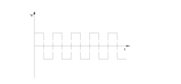
一つの実施可能な形態としては、ステップS203では、液体吐出ピペットチップ110の出口端112が第二の液体の液面下に周期的に運動する工程に、液体吐出ピペットチップ110の出口端112の速度が長方形波状に変化する。液体吐出ピペットチップ110の出口端112の速度が長方形波状に変化し、加速段階が終わった直後に均一な速度の段階に移行することは、運動制御機構130により液体吐出ピペットチップ110の出口端112の運動状態を正確に制御することに役立つ。好ましくは、液体吐出ピペットチップ110の出口端112による運動速度の変化の長方形波状を示すハイレベルタイミング及びローレベルタイミングは、同等でもよく相違でもよい。さらに、ステップS203では、液体吐出ピペットチップ110の出口端112が第二の液体の液面下に周期的に運動する工程に、液体吐出ピペットチップ110の出口端112の速度が方形波状に変化する。液体吐出ピペットチップ110の出口端112による運動速度の変化の長方形波状を示すハイレベルタイミングとローレベルタイミングとは、等しい。液体吐出ピペットチップ110の出口端112による運動速度の変化を示す長方形波状がローレベルにある場合に、液体吐出ピペットチップ110の出口端112は、その速度がセロとなり、又は、ハイレベルにある方向と反対方向の速度を有する。図4に示されるように、さらに、前記液体吐出ピペットチップ110の出口端112が周期的に運動している周期の前半及び後半において、前記液体吐出ピペットチップ110の出口端112の速度は、その大きさが同じであり、かつ方向が反対している。液体吐出ピペットチップ110の出口端112の一つの運動周期には、二つの反対方向の瞬間加速度運動が含まれる。 In one possible embodiment, in step S203, while the outlet end 112 of the liquid-dispensing pipette tip 110 is periodically moving below the surface of the second liquid, the outlet end 112 of the liquid-dispensing pipette tip 110 is moved. Velocity changes in rectangular waves. The change in velocity at the outlet end 112 of the liquid dispensing pipette tip 110 in a rectangular wave and transition to a uniform velocity phase immediately after the acceleration phase is completed is controlled by the motion control mechanism 130 to cause the outlet end 112 of the liquid dispensing pipette tip 110 to move. It helps to precisely control the state of motion of the body. Preferably, the high-level timing and low-level timing representing the rectangular waveform of change in velocity of motion by the outlet end 112 of the liquid dispensing pipette tip 110 may be the same or different. Further, in step S203, the velocity of the outlet end 112 of the liquid-dispensing pipette tip 110 changes in a square wave during the step of periodically moving the outlet end 112 of the liquid-dispensing pipette tip 110 below the surface of the second liquid. . The high level timing and the low level timing of the rectangular waveform of change in velocity of movement by the outlet end 112 of the liquid dispensing pipette tip 110 are equal. The outlet end 112 of the liquid-dispensing pipette tip 110 moves in the direction in which its speed is zero or is at a high level when the rectangular wave that indicates the change in motion velocity by the outlet end 112 of the liquid-dispensing pipette tip 110 is at a low level. has a velocity in the opposite direction to Further, as shown in FIG. 4, in the first and second halves of the cycle in which the outlet end 112 of the liquid-dispensing pipette tip 110 periodically moves, the velocity of the outlet end 112 of the liquid-dispensing pipette tip 110 is Same size and opposite direction. One motion cycle of the outlet end 112 of the liquid dispensing pipette tip 110 includes instantaneous acceleration motions in two opposite directions.

本実施例では、液体吐出ピペットチップ110の出口端112が第二の液体の液面下に運動している軌跡は、直線セグメントである。液体吐出ピペットチップ110の出口端112は、直線セグメントの一方の端点から瞬間加速度運動を行い、直線セグメントの他方の端点から反対方向に瞬間加速度運動を行う。二つの瞬間加速度運動の加速度は、いずれもa1である。他の実施例では、液体吐出ピペットチップ110の出口端112が第二の液体の液面下に運動している軌跡は、円弧セグメント又は多角形形状である。さらに、ステップS203では、液体吐出ピペットチップ110の出口端112が第二の液体の液面下に周期的に運動する周波数は、0.1Hz~200Hzの範囲にあることから、プロジェクトでは実現され易い。 In this example, the trajectory along which the outlet end 112 of the liquid dispensing pipette tip 110 is moving below the surface of the second liquid is a straight line segment. The outlet end 112 of the liquid dispensing pipette tip 110 undergoes instantaneous acceleration motion from one end point of the linear segment and instantaneous acceleration motion in the opposite direction from the other end point of the linear segment. The acceleration of the two instantaneous acceleration motions is a1 . In other embodiments, the trajectory along which outlet end 112 of liquid-dispensing pipette tip 110 moves below the surface of the second liquid is an arc segment or polygonal shape. Furthermore, in step S203, the frequency at which the outlet end 112 of the liquid-dispensing pipette tip 110 cyclically moves below the surface of the second liquid is in the range of 0.1 Hz to 200 Hz. .

図4及び図5に示されるように、本出願に係る一つの具体的な実施例では、流体駆動機構120は、第一の液体を一定の流速で液体吐出ピペットチップ110の出口端112から排出するように制御する。運動制御機構130は、液体吐出ピペットチップ110の出力端が、直線状に運動する軌跡或いは方形波状に変化する速度で周期的に運動するように制御する。液体吐出ピペットチップ110の出口端112の速度方向が変更されると、液体吐出ピペットチップ110の出口端112は瞬間加速度が最大値になる。液体吐出ピペットチップ110の出口端112に付着された液滴195も、液体吐出ピペットチップ110の出口端112に瞬間加速度が最大値になる時に、液体吐出ピペットチップ110の出口端112から脱離され、微小液滴199を形成する。第一の液体が一定流速で液体吐出ピペットチップ110の出口端112から排出されることから、液滴195が液体吐出ピペットチップ110の出口端112から脱落したときに、新たな液滴195が生成状態に移行する。液体吐出ピペットチップ110の出口端112が再度、反対方向に加速すると、新しく生成された液滴195も液体吐出ピペットチップ110の出口端112から脱落されて新たな微小液滴199を形成する。 As shown in FIGS. 4 and 5, in one specific embodiment of the present application, the fluid drive mechanism 120 expels the first liquid from the outlet end 112 of the liquid dispensing pipette tip 110 at a constant flow rate. control to The motion control mechanism 130 controls the output end of the liquid-discharging pipette tip 110 so that it periodically moves along a trajectory moving linearly or at a speed changing like a square wave. When the velocity direction of the outlet end 112 of the liquid dispensing pipette tip 110 is changed, the outlet end 112 of the liquid dispensing pipette tip 110 reaches a maximum instantaneous acceleration. A droplet 195 attached to the outlet end 112 of the liquid-dispensing pipette tip 110 is also detached from the outlet end 112 of the liquid-dispensing pipette tip 110 when the instantaneous acceleration at the outlet end 112 of the liquid-dispensing pipette tip 110 reaches the maximum value. , forming microdroplets 199 . Because the first liquid is ejected from the outlet end 112 of the liquid dispensing pipette tip 110 at a constant flow rate, a new droplet 195 is generated when the droplet 195 falls off the outlet end 112 of the liquid dispensing pipette tip 110. transition to state. When the exit end 112 of the liquid dispensing pipette tip 110 accelerates again in the opposite direction, the newly created droplets 195 are also shed from the exit end 112 of the liquid dispensing pipette tip 110 to form new microdroplets 199 .

本実施例では、液体吐出ピペットチップ110の出口端112が一つの運動周期に二つの微小液滴199を生成可能であり、しかも、方形波状がプロジェクトで実現され易い。他の実施例では、液体吐出ピペットチップ110の出口端112が一つの運動周期に一つの微小液滴199を生成する。実施例において、液体吐出ピペットチップ110の出口端112は、第二の液体699に、任意方向に沿って直線状の軌跡で、速度が方形波状で変化する運動を行うことが好ましい。この運動には、液体吐出ピペットチップ110の延在方向と垂直する平面に直線状の軌跡で速度が方形波状で変化する運動、液体吐出ピペットチップ110の延在方向と任意角度をなす平面に直線状の軌跡で速度が方形波状で変化する運動、及び、液体吐出ピペットチップ110の延在方向に沿って直線状の軌跡で速度が方形波状で変化する運動などが含まれる。本出願に係る他の実施例では、液体吐出ピペットチップ110の出口端112の運動軌跡が円弧セグメント又は多角形形状である場合に、液体吐出ピペットチップ110の出口端112が第二の液体699に任意方向に沿って円弧セグメント又は多角形形状の軌跡で速度が方形波状で変化する運動を行う。この運動には、液体吐出ピペットチップ110の延在方向と垂直する平面に円弧セグメント又は多角形形状の軌跡で速度が方形波状で変化する運動、液体吐出ピペットチップ110の延在方向と任意角度をなす平面に直線状の軌跡で方形波状となる運動、及び、液体吐出ピペットチップ110の延在方向に沿って速度が方形波状で変化する軌跡による運動などが含まれる。 In this embodiment, the exit end 112 of the liquid dispensing pipette tip 110 can produce two micro-droplets 199 in one movement period, and the square wave shape is easy to achieve in the project. In another embodiment, the outlet end 112 of the liquid dispensing pipette tip 110 produces one microdroplet 199 in one motion cycle. In an embodiment, the outlet end 112 of the liquid dispensing pipette tip 110 preferably causes the second liquid 699 to move in a linear trajectory along any direction with a square wave of varying velocity . This motion includes a motion in which the velocity changes in a square wave shape along a linear trajectory in a plane perpendicular to the extending direction of the liquid-dispensing pipette tip 110, and a linear motion in a plane that forms an arbitrary angle with the extending direction of the liquid-dispensing pipette tip 110. A motion in which the speed changes in a square wave shape along a linear locus and a motion in which the speed changes in a square wave shape along a linear locus along the extending direction of the liquid-discharging pipette tip 110 are included. In other embodiments according to the present application, the outlet end 112 of the liquid dispensing pipette tip 110 moves toward the second liquid 699 when the motion trajectory of the outlet end 112 of the liquid dispensing pipette tip 110 is an arc segment or a polygonal shape. A motion with a square wave-like change in velocity is performed on an arc segment or a polygonal trajectory along an arbitrary direction. This motion includes a motion in which the velocity changes in a square wave shape on a plane perpendicular to the extending direction of the liquid-dispensing pipette tip 110 in an arc segment or a polygonal trajectory, and a motion in which the speed changes in the shape of a square wave with respect to the extending direction of the liquid-dispensing pipette tip 110 . The movement includes a square-wave-like motion with a linear trajectory on a plane to form, and a motion with a trajectory whose velocity changes in a square-wave-like manner along the extending direction of the liquid-discharging pipette tip 110 .

本出願に係る他の実施例では、運動制御機構130の連動により、液体吐出ピペットチップ110の出口端112は、第二の液体の液面下に周期的に変化する速度で運動を行い、速度が変化している周期の前半及び後半において、液体吐出ピペットチップ110の出口端112の速度が共に単調変化している。単調変化しているとは、速度が変化している周期の前半及び後半において、液体吐出ピペットチップ110の出口端112の次の時刻の速度が常に先の時刻の速度以上又は以下であることを意味している。例えば、速度が変化している周期の前半に、液体吐出ピペットチップ110の出口端112の速度が持続的に増加し、或いは、一部分の速度が持続的に増加して一部分の速度が変化しない。一方、速度が変化している周期の後半において、液体吐出ピペットチップ110の出口端112の速度が持続的に減少し、又は、一部分の速度が持続的に減少して一部分の速度が変化しない。第一の液体は、液体吐出ピペットチップ110の出口端112から排出され、液体吐出ピペットチップ110の出口端112に付着される液滴195を形成する。液滴195は、液体吐出ピペットチップ110の出口端112の運動速度がある大きさになると、液体吐出ピペットチップ110の出口端112から脱離され、微小液滴199を形成する。図6に示されるように、微小液滴199が液体吐出ピペットチップ110の出口端112から脱離されるまで、受けられた作用力は、それぞれ、重力G、第二の液体699の浮力f1、第二の液体699の粘性抵抗f2、及び、液体吐出ピペットチップ110の出口端112と液滴195との最大の付着力f3である。微小液滴199について、液体吐出ピペットチップ110の出口端112から脱離されるまでの質量をmとし、速度をvとし、加速度をa2とすると、液滴195は、第二の液体699の運動工程において、粘性力f2、重力G、浮力f1及び付着力f3による相乗効果により受けられており、

Figure 0007220366000003
In another embodiment of the present application, the motion control mechanism 130 is interlocked to cause the outlet end 112 of the liquid dispensing pipette tip 110 to move at a cyclically varying speed below the surface of the second liquid, and the speed In the first and second halves of the cycle in which is changing, the velocity of the exit end 112 of the liquid-dispensing pipette tip 110 both changes monotonously. Monotonically changing means that the velocity of the outlet end 112 of the liquid-dispensing pipette tip 110 at the next time is always higher or lower than the velocity at the previous time in the first and second halves of the cycle in which the speed is changing. means. For example, in the first half of the cycle in which the velocity is changing, the velocity of the exit end 112 of the liquid dispensing pipette tip 110 increases continuously, or the velocity of a part increases continuously and the velocity of a part does not change. On the other hand, in the second half of the cycle in which the velocity is changing, the velocity of the outlet end 112 of the liquid dispensing pipette tip 110 is continuously decreased, or the velocity of a part is continuously decreased and the velocity of a part is not changed. The first liquid is expelled from the outlet end 112 of the liquid dispensing pipette tip 110 and forms a droplet 195 that adheres to the outlet end 112 of the liquid dispensing pipette tip 110 . Droplet 195 is detached from outlet end 112 of liquid ejection pipette tip 110 to form microdroplet 199 when the velocity of movement of outlet end 112 of liquid ejection pipette tip 110 reaches a certain magnitude. As shown in FIG. 6, until the microdroplet 199 is detached from the outlet end 112 of the liquid dispensing pipette tip 110, the applied forces are the gravity G, the buoyancy force f1 of the second liquid 699, respectively. The viscous drag f 2 of the second liquid 699 and the maximum adhesion force f 3 between the outlet end 112 of the liquid dispensing pipette tip 110 and the droplet 195 . Assuming that the mass of the minute droplet 199 until it is detached from the outlet end 112 of the liquid-dispensing pipette tip 110 is m, the velocity is v, and the acceleration is a 2 , the droplet 195 follows the motion of the second liquid 699. In the process, it is received by the synergistic effect of viscous force f2 , gravity G, buoyant force f1 and adhesive force f3 ,
Figure 0007220366000003

液体吐出ピペットチップ110の出口端112と液滴195との付着力の最大値f3は、液体吐出ピペットチップ110の表面自由エネルギー、液滴195の表面張力、及び、液体吐出ピペットチップ110の幾何学的寸法に関連されている。液体吐出ピペットチップ110の出口端112に付着された液滴195を球状として簡略化する。ストークス(Stokes)の式によると、わかるように、第二の液体699中を運動するときに受けられた液滴195の粘性抵抗がf2=6πηrvとなり、そのうち、ηが第二の液体699の粘性係数であり、rが液滴195の半径であり、vが液滴195の運動速度である。微小液滴199を生成する工程において、一般的に、液滴195の直径範囲は、ピコリットルからマイクロリットルまでのオーダーであり、第二の液体699の粘性係数は、一般的に、比較的大きい。

Figure 0007220366000004
The maximum value f3 of the adhesive force between the exit end 112 of the liquid ejection pipette tip 110 and the droplet 195 depends on the surface free energy of the liquid ejection pipette tip 110, the surface tension of the droplet 195, and the geometry of the liquid ejection pipette tip 110. related to the physical dimensions. Droplet 195 attached to exit end 112 of liquid dispensing pipette tip 110 is simplified as being spherical. According to the Stokes equation, as can be seen, the viscous drag experienced by the droplet 195 as it moves through the second liquid 699 is f 2 =6πηrv, where η is the force of the second liquid 699 is the viscosity coefficient, r is the radius of droplet 195 and v is the velocity of motion of droplet 195 . In the process of generating microdroplets 199, typically the diameter range of droplets 195 is on the order of picoliters to microliters, and the viscosity coefficient of second liquid 699 is typically relatively large. .
Figure 0007220366000004

このことに鑑み、本出願が提供する微小液滴生成方法は、出口端112を有し、第一の液体を貯留している液体吐出ピペットチップ110を提供し、開口を有し、第二の液体699を貯留している微小液滴容器60を提供し、第一の液体と第二の液体699とは、互いに非相溶性を持ち又は界面反応を有する任意の二つの液体とされるステップS211と、液体吐出ピペットチップ110の出口端112を、微小液滴容器60の開口から第二の液体699の液面下に挿入するステップS212と、液体吐出ピペットチップ110の出口端112に、第二の液体699の液面下に速度が周期変化する運動を行わせ、速度が変化している周期の前半及び後半において、液体吐出ピペットチップ110の出口端112の速度が共に単調変化しながら、第一の液体を液体吐出ピペットチップ110の出口端112から均一な速度で排出し、液体吐出ピペットチップ110の出口端112から排出された第一の液体は、液体吐出ピペットチップ110の出口端112に付着された液滴195を形成し、液滴195は、液体吐出ピペットチップ110の出口端112が運動している工程に、液体吐出ピペットチップ110の出口端112から脱離され、第二の液体699の液面下に微小液滴199を形成するステップS213と、を含む。
上記の微小液滴生成方法によれば、液体吐出ピペットチップ110の出口端112は、第二の液体699の液面下に周期的に変化する速度で運動を行い、速度が変化している周期の前半及び後半において、液体吐出ピペットチップ110の出口端112の速度が共に単調変化する。運動の工程では、液滴195に対する第二の液体699の粘性力f2も、液体吐出ピペットチップ110の出口端112の速度が周期的に変化するのに伴い周期的に変化する。液体吐出ピペットチップ110の出口端112と液滴195との最大の付着力f3が液滴195に対する第二の液体699の粘性力 f2よりも小さいと、液滴195が液体吐出ピペットチップ110の出口端112と同期に運動することができなくなり、前記液体吐出ピペットチップ110の出口端112に付着された液滴195が前記液体吐出ピペットチップ110の出口端112から脱離され、第二の液体699の液面下に微小液滴199を形成する。
In view of this, the microdroplet generating method provided by the present application provides a liquid dispensing pipette tip 110 having an outlet end 112 and containing a first liquid, having an opening and a second liquid. Step S211 of providing a microdroplet reservoir 60 containing a liquid 699, wherein the first liquid and the second liquid 699 are any two liquids that are immiscible with each other or have an interfacial reaction. In step S212, the outlet end 112 of the liquid-discharging pipette tip 110 is inserted below the surface of the second liquid 699 from the opening of the microdroplet container 60; In the first and second halves of the cycle in which the speed is changing, the speed of the outlet end 112 of the liquid-dispensing pipette tip 110 changes monotonically. One liquid is ejected from the outlet end 112 of the liquid-dispensing pipette tip 110 at a uniform rate, and the first liquid ejected from the outlet end 112 of the liquid-dispensing pipette tip 110 is discharged to the outlet end 112 of the liquid-dispensing pipette tip 110. Forming a deposited droplet 195, the droplet 195 is detached from the outlet end 112 of the liquid dispensing pipette tip 110 in a step in which the outlet end 112 of the liquid dispensing pipette tip 110 is in motion, and a second liquid is deposited. forming a microdroplet 199 below the liquid surface of 699 S213.
According to the microdroplet generation method described above, the outlet end 112 of the liquid-discharging pipette tip 110 moves at a periodically changing speed below the surface of the second liquid 699, and the speed changes periodically. , both the velocity of the exit end 112 of the liquid-dispensing pipette tip 110 changes monotonically. During the course of motion, the viscous force f 2 of the second liquid 699 on the droplet 195 also changes periodically as the velocity of the exit end 112 of the liquid dispensing pipette tip 110 changes periodically. If the maximum adhesion force f 3 between the outlet end 112 of the liquid dispensing pipette tip 110 and the droplet 195 is less than the viscous force f 2 of the second liquid 699 on the droplet 195 , then the droplet 195 will adhere to the liquid dispensing pipette tip 110 . can no longer move synchronously with the outlet end 112 of the liquid-dispensing pipette tip 110, and the droplet 195 adhered to the outlet end 112 of the liquid-dispensing pipette tip 110 is detached from the outlet end 112 of the liquid-dispensing pipette tip 110, and the second A microdroplet 199 is formed below the liquid surface of the liquid 699 .

本出願が提供する微小液滴生成方法は、前記液体吐出ピペットチップ110の出口端112が第二の液体699の液面下に周期的に変化する速度で運動を行い、微小液滴199を生成することにより、前記液体吐出ピペットチップ110の出口端112が運動している時に第二の液体699に与える干渉を減少し、微小液滴199を生成する工程に安定性を確保することができる。 According to the microdroplet generation method provided by the present application, the outlet end 112 of the liquid ejection pipette tip 110 moves under the surface of the second liquid 699 at a periodically varying speed to generate the microdroplets 199. By doing so, it is possible to reduce interference with the second liquid 699 when the outlet end 112 of the liquid discharge pipette tip 110 is moving, and to ensure stability in the process of generating the minute droplets 199 .

本実施例では、ステップS213に、第一の液体が液体吐出ピペットチップ110の出口端112から連続して排出される。さらに、ステップS213に、第一の液体が液体吐出ピペットチップ110の出口端112から一定の流速で排出される。このことは、等時間間隔に、液体吐出ピペットチップ110の出口端112から排出された第一の液体の体積が常に同じであることを意味している。第一の液体が液体吐出ピペットチップ110の出口端112から一定の流速で排出されると、液体吐出ピペットチップ110の出口端112が周期的に運動するように制御することにより、体積の一致する微小液滴199を生成することに役立つ。 In this embodiment, the first liquid is continuously expelled from the outlet end 112 of the liquid dispensing pipette tip 110 in step S213. Further, in step S213, the first liquid is expelled from the outlet end 112 of the liquid dispensing pipette tip 110 at a constant flow rate. This means that the volume of the first liquid expelled from the outlet end 112 of the liquid-dispensing pipette tip 110 at equal time intervals is always the same. When the first liquid is ejected from the outlet end 112 of the liquid-dispensing pipette tip 110 at a constant flow rate, volume matching is achieved by controlling the periodic motion of the outlet end 112 of the liquid-dispensing pipette tip 110 . Helps generate microdroplets 199 .

第二の液体699の中を運動している時に受けられた液滴195の粘性抵抗f2に影響を与える要素には、液滴195の運動速度vのほうが制御されやすい。液滴195は、液体吐出ピペットチップ110の出口端112から脱離され微小液滴199を形成するまで、液体吐出ピペットチップ110の出口端112と同期に運動することが保持される。従って、液体吐出ピペットチップ110の出口端112の運動速度を制御することにより、液滴195の運動速度vを正確に制御することができる。第一の液体を均一な流速で液体吐出ピペットチップ110の出口端112から排出するように制御すると、液滴195の半径rが一定の時間間隔に周期的に変化する。第二の液体699の中を運動している時に受けられた液滴195の粘性抵抗 f2に影響を与える要素には、第二の液体699の粘性係数ηが、使用される工程において、ある範囲で変化するものの、第二の液体699の粘性係数ηの変化する範囲は極めて小さい。 Of the factors affecting the viscous resistance f 2 of the droplet 195 received while moving through the second liquid 699, the motion velocity v of the droplet 195 is more easily controlled. Droplet 195 is held in synchronous motion with outlet end 112 of liquid dispensing pipette tip 110 until it detaches from outlet end 112 of liquid dispensing pipette tip 110 to form microdroplet 199 . Therefore, by controlling the velocity of motion of the outlet end 112 of the liquid dispensing pipette tip 110, the velocity v of the droplet 195 can be precisely controlled. Controlling the first liquid to discharge from the outlet end 112 of the liquid ejection pipette tip 110 at a uniform flow rate causes the radius r of the droplet 195 to change periodically at regular time intervals. Among the factors affecting the viscous drag f 2 of the droplet 195 experienced while moving through the second liquid 699 is the viscosity coefficient η of the second liquid 699 in the process used. Although it varies over a range, the range over which the viscosity coefficient η of the second liquid 699 varies is extremely small.

液体吐出ピペットチップ110及び第一の液体が交換されない場合に、液体吐出ピペットチップ110の表面自由エネルギー、液体吐出ピペットチップ110の幾何学的寸法、及び、液滴195の表面張力は、液体吐出ピペットチップ110の出口端112と液滴195との最大の付着力 f3に影響を与える二つの要素として、変化しない。従って、液体吐出ピペットチップ110及び第一の液体が交換されない場合に、液体吐出ピペットチップ110の出口端112と液滴195との付着力の最大値 f3が変化しない。複数の液体吐出ピペットチップ110により同時又は順次に微小液滴199を生成すると、液体吐出ピペットチップ110の表面自由エネルギー及び液体吐出ピペットチップ110の幾何学的寸法は、液体吐出ピペットチップ110の出口端112と液滴195との最大の付着力 f3に影響を与える二つの要素として、変化する。しかしながら、多量で加工される場合に、液体吐出ピペットチップ110の表面自由エネルギー及び液体吐出ピペットチップ110の幾何学的寸法が一定の区間に変化するように制御可能である。液体吐出ピペットチップ110の出口端112と液滴195との最大の付着力 f3に影響を与えるもう一つの要素である液滴195の表面張力は、極めて小さい範囲でのみ変化する。液体吐出ピペットチップ110の出口端112と液滴195との付着力の最大値 f3は、極めて小さい区間にのみ波動する。 If the liquid dispensing pipette tip 110 and the first liquid are not exchanged, the surface free energy of the liquid dispensing pipette tip 110, the geometrical dimensions of the liquid dispensing pipette tip 110, and the surface tension of the liquid droplet 195 are As the two factors affecting the maximum adhesion force f 3 between the exit end 112 of the tip 110 and the droplet 195 remain unchanged. Therefore, the maximum value f 3 of the adhesive force between the outlet end 112 of the liquid-dispensing pipette tip 110 and the droplet 195 does not change when the liquid-dispensing pipette tip 110 and the first liquid are not replaced. When microdroplets 199 are generated simultaneously or sequentially by a plurality of liquid ejection pipette tips 110, the surface free energy of the liquid ejection pipette tips 110 and the geometrical dimensions of the liquid ejection pipette tips 110 are reduced to the exit end of the liquid ejection pipette tips 110. Vary as two factors affecting the maximum adhesion force f 3 between 112 and droplet 195 . However, when processed in large quantities, the surface free energy of the liquid-dispensing pipette tip 110 and the geometrical dimensions of the liquid-dispensing pipette tip 110 can be controlled to change in a certain interval. The surface tension of droplet 195, another factor affecting the maximum adhesion force f 3 between outlet end 112 of liquid dispensing pipette tip 110 and droplet 195, varies only within a very small range. The maximum value f 3 of the adhesive force between the outlet end 112 of the liquid ejection pipette tip 110 and the droplet 195 fluctuates only in a very small interval.

従って、第二の液体699の中を運動している時に受けられた液滴195の粘性抵抗 f2が液体吐出ピペットチップ110の出口端112と液滴195との付着力の最大値 f3の区間値よりも大きいように制御できればよい。同じバッチで微小液滴199を生成する工程には、液滴195の半径rが必ず変化しない。一旦、試験用のパラメータが確定されると、液滴195の半径rも、それに伴い、確定された。液体吐出ピペットチップ110の出口端112が第二の液体699の液面下に運動する速度は、変化する。液体吐出ピペットチップ110の出口端112が第二の液体699の液面下に運動する速度は、v>f3/6πηrが満たされているときに、液滴195が液体吐出ピペットチップ110の出口端112から脱離され、微小液滴199を形成する。 Therefore, the viscous resistance f 2 of the droplet 195 received while moving through the second liquid 699 is the maximum value f 3 of the adhesion force between the outlet end 112 of the liquid-dispensing pipette tip 110 and the droplet 195 . It is sufficient if it can be controlled to be larger than the interval value. The process of producing microdroplets 199 in the same batch does not necessarily change the radius r of the droplets 195 . Once the parameters for the test were established, the radius r of droplet 195 was established accordingly. The speed at which the exit end 112 of the liquid dispensing pipette tip 110 moves below the surface of the second liquid 699 varies. The velocity at which the exit end 112 of the liquid-dispensing pipette tip 110 moves below the surface of the second liquid 699 is such that the droplet 195 moves to the exit of the liquid-dispensing pipette tip 110 when v>f 3 /6πηr is satisfied. Detached from edge 112 to form microdroplet 199 .

液体吐出ピペットチップ110の出口端112は、第二の液体699の液面下に周期的に変化する速度で運動を行う。第一の液体を均一な流速で液体吐出ピペットチップ110の出口端112から排出するように制御すると、液体吐出ピペットチップ110の出口端112に付着される液滴195の体積も均一に増大する。一番目の微小液滴199が液体吐出ピペットチップ110の出口端112から落下したときの微小液滴199の半径は臨界半径と呼ばれ、微小液滴199の速度は臨界速度と呼ばれる。液体吐出ピペットチップ110の出口端112の運動周期、及び、液体吐出ピペットチップ110の出口端112から排出された第一の液体の流速を調整することにより、同じ時間間隔(液体吐出ピペットチップ110の出口端112の運動周期の倍数)が経過した後に、液体吐出ピペットチップ110の出口端112に付着される液滴195が同時に臨界半径及び臨界速度になり、新たな微小液滴199を形成する。第一の液体が均一な流速で液体吐出ピペットチップ110の出口端112から排出されることから、生成された微小液滴199の体積が同じくなる。 The outlet end 112 of the liquid-dispensing pipette tip 110 moves at a periodically varying velocity below the surface of the second liquid 699 . Controlling the first liquid to discharge from the outlet end 112 of the liquid-dispensing pipette tip 110 at a uniform flow rate also uniformly increases the volume of the droplets 195 adhering to the outlet end 112 of the liquid-dispensing pipette tip 110 . The radius of the first microdroplet 199 as it falls from the exit end 112 of the liquid dispensing pipette tip 110 is called the critical radius, and the velocity of the microdroplet 199 is called the critical velocity. By adjusting the movement period of the outlet end 112 of the liquid-dispensing pipette tip 110 and the flow rate of the first liquid ejected from the outlet end 112 of the liquid-dispensing pipette tip 110, the same time interval ( After a multiple of the period of motion of the outlet end 112 , the droplet 195 deposited on the outlet end 112 of the liquid dispensing pipette tip 110 simultaneously reaches the critical radius and critical velocity and forms a new microdroplet 199 . Since the first liquid is ejected from the outlet end 112 of the liquid ejection pipette tip 110 at a uniform flow rate, the volumes of microdroplets 199 produced will be the same.

一つの実施可能な形態として、ステップS213に、速度が変化している一つの周期に、液体吐出ピペットチップ110の出口端112の速度が中間時点を中点として中心対称である。さらに、ステップS213に、第二の液体699の液面下に液体吐出ピペットチップ110の出口端112の加速度、速度及び運動軌跡がいずれも周期的に変化する。また、ステップS213に、第二の液体699の液面下に液体吐出ピペットチップ110の出口端112の速度が余弦曲線状に変化する。 In one possible embodiment, in step S213, the velocity of the outlet end 112 of the liquid-dispensing pipette tip 110 is centrosymmetric about the midpoint during one period of varying velocity. Further, in step S213, the acceleration, velocity and motion trajectory of the outlet end 112 of the liquid-dispensing pipette tip 110 under the surface of the second liquid 699 all change periodically. Also, in step S213, the velocity of the outlet end 112 of the liquid-dispensing pipette tip 110 below the surface of the second liquid 699 changes cosine curve.

選択的に、ステップS213には、液体吐出ピペットチップ110の出口端112が第二の液体699の液面下に運動している軌跡は、直線セグメント、円弧セグメント、多角形形状などの複数の種類の軌跡のうち一つ又は複数の組み合わせが含まれる。ステップS213には、液体吐出ピペットチップ110の出口端112が第二の液体699の液面下に周期的に運動する周波数が0.1Hz~200Hzの範囲にあることから、プロジェクトで実現され易い。 Optionally, in step S213, the trajectory along which the outlet end 112 of the liquid-dispensing pipette tip 110 moves below the surface of the second liquid 699 may be of multiple types, such as straight line segments, arc segments, polygonal shapes, and the like. trajectories, or a combination of more than one. Step S213 is easy to implement in the project because the frequency at which the outlet end 112 of the liquid-dispensing pipette tip 110 cyclically moves below the surface of the second liquid 699 is in the range of 0.1 Hz to 200 Hz.

液体吐出ピペットチップ110の出口端112は、第二の液体699の液面下に円弧の軌跡で、又は、余弦状に変化する速度で周期的な運動を行うことを例として挙げると、このとき、液体吐出ピペットチップ110の出口端112は、実際に揺動するように運動し、運動変位が正弦波状の曲線で示される。図7における曲線aに示されるように、流体制御機構の駆動により、第一の液体が均一な流速で液体吐出ピペットチップ110の出口端112から排出される。仮に液滴195が液体吐出ピペットチップ110の出口端112から脱離されないとすると、計算により、第二の液体699の中を運動している時に受けられた液滴195の粘性抵抗fが、時間の経過に伴い、図7における曲線bとして示されている。第一の液体が均一な流速で液体吐出ピペットチップ110の出口端112から排出される初期の段階に、液滴195の体積が増大していくのに伴い、液滴195の半径rも明らかに増大している。液滴195の半径rが増大するのに伴い、液滴195の体積が均一な速度で増大していくことから、液滴195の半径rが緩く増大していくことが余儀無くされる。従って、液体吐出ピペットチップ110の出口端112が揺動する初期の複数の周期に、第二の液体699の中を運動している時に受けられた液滴195の粘性抵抗f2の最大値が急速に増加し、その後、緩く増加している。図7に示されるように、第二の液体699の中を運動している時に受けられた液滴195の粘性抵抗 f2も液体吐出ピペットチップ110の出口端112の周期的な運動と類似する周期性が現れ、即ち、第二の液体699の中を運動している時に受けられた液滴195の粘性抵抗 f2が液体吐出ピペットチップ110の出口端112の速度変化に伴い変化する。実際の状況では、第二の液体699の中を運動している時に受けられた液滴195の粘性抵抗 f2が増大し、しかも、液体吐出ピペットチップ110の出口端112と液滴195との付着力の最大値 f3よりも大きい場合に、液滴195が液体吐出ピペットチップ110の出口端112から脱落され、微小液滴199を形成する。 As an example, the exit end 112 of the liquid dispensing pipette tip 110 makes a periodic motion below the surface of the second liquid 699 in an arc locus or with a cosinusoidally varying velocity. , the outlet end 112 of the liquid-dispensing pipette tip 110 actually rocks, and the motion displacement is represented by a sinusoidal curve. As shown by curve a in FIG. 7, the fluid control mechanism is driven to eject the first liquid from the outlet end 112 of the liquid dispensing pipette tip 110 at a uniform flow rate. Assuming that droplet 195 does not detach from outlet end 112 of liquid dispensing pipette tip 110, calculations show that the viscous drag f experienced by droplet 195 as it moves through second liquid 699 increases over time is shown as curve b in FIG. As the volume of the droplet 195 increases during the initial stage when the first liquid is ejected from the outlet end 112 of the liquid dispensing pipette tip 110 with a uniform flow rate, the radius r of the droplet 195 also becomes apparent. increasing. Since the volume of the droplet 195 increases at a uniform rate as the radius r of the droplet 195 increases, the radius r of the droplet 195 is forced to increase slowly. Thus, during the initial cycles of oscillation of outlet end 112 of liquid dispensing pipette tip 110, the maximum value of viscous drag f2 experienced by droplet 195 as it moves through second liquid 699 is It increases rapidly and then increases slowly. As shown in FIG. 7, the viscous resistance f 2 of the droplet 195 experienced while moving through the second liquid 699 is also analogous to the periodic motion of the outlet end 112 of the liquid dispensing pipette tip 110 . A periodicity appears, ie, the viscous resistance f 2 of the droplet 195 encountered while moving through the second liquid 699 changes with the velocity change of the outlet end 112 of the liquid dispensing pipette tip 110 . In a practical situation, the viscous resistance f 2 of the droplet 195 experienced while moving through the second liquid 699 increases, and moreover, the droplet 195 and the exit end 112 of the liquid-dispensing pipette tip 110 Droplet 195 sloughs off exit end 112 of liquid dispensing pipette tip 110 to form microdroplet 199 when the adhesion force is greater than the maximum value f 3 .

本出願の一実施例では、図8に示されるように、液体吐出ピペットチップ110の出口端112が、円弧の軌跡、または、正弦波状の変位で揺動するように制御する。液体吐出ピペットチップ110及び第一の液体が交換されない場合に、液体吐出ピペットチップ110の出口端112と液滴195との付着力の最大値 f3が変化しない。液体吐出ピペットチップ110の出口端112に付着される液滴195の半径rが増大するのに伴い、第二の液体699の中を運動している時に受けられた液滴195の粘性抵抗 f2も持続的に増大する。第二の液体699の中を運動している時に受けられた液滴195の粘性抵抗 f2が液体吐出ピペットチップ110の出口端112と液滴195との付着力の最大値f3よりも大きい瞬間に、液滴195が液体吐出ピペットチップ110の出口端112から脱落され、図8に示される液滴Iとなるように、微小液滴199を形成する。そして、次の微小液滴199を生成するサイクルへ移行する。 In one embodiment of the present application, as shown in FIG. 8, the outlet end 112 of the liquid dispensing pipette tip 110 is controlled to oscillate in an arcuate trajectory or sinusoidal displacement. If the liquid-dispensing pipette tip 110 and the first liquid are not exchanged, the maximum adhesion force f 3 between the outlet end 112 of the liquid-dispensing pipette tip 110 and the droplet 195 does not change. As the radius r of the droplet 195 deposited at the outlet end 112 of the liquid dispensing pipette tip 110 increases, the viscous drag f 2 of the droplet 195 experienced while moving through the second liquid 699 is also continue to increase. The viscous drag f2 of the droplet 195 experienced while moving through the second liquid 699 is greater than the maximum adhesion force f3 between the outlet end 112 of the liquid dispensing pipette tip 110 and the droplet 195. Momentarily, droplet 195 falls off exit end 112 of liquid dispensing pipette tip 110 and forms microdroplet 199, resulting in droplet I shown in FIG. Then, the process shifts to the cycle for generating the next minute droplet 199 .

本実施例では、液体吐出ピペットチップ110の出口端112と液滴195との付着力の最大値がf3=1.8x10⁻⁴Nとなり、液体吐出ピペットチップ110の出口端112の揺動周波数が50Hzである。液体吐出ピペットチップ110の出口端112が正弦波状に変位して揺動する運動を行う二番目の周期の最後に、図8における液滴Iとなるように一番目の微小液滴199を生成する。二番目の微小液滴199を生成する初期段階に、液体吐出ピペットチップ110の出口端112の運動速度が僅かに減少するが、液体吐出ピペットチップ110の出口端112に付着された液滴195の半径rが速く増加していることから、第二の液体699に運動している時に受けられた液滴195の粘性抵抗f2が、直ぐに低下することなく、小さい範囲に増加する。そして、液滴195の半径rが緩く増加し、第二の液体699の中を運動している時に受けられた液滴195の粘性抵抗 f2が、主に、液体吐出ピペットチップ110の出口端112の運動の速度変化に伴い、変化する。 In this embodiment, the maximum adhesive force between the outlet end 112 of the liquid-discharging pipette tip 110 and the droplet 195 is f 3 =1.8×10 −4 N, and the oscillation frequency of the outlet end 112 of the liquid-discharging pipette tip 110 is 50 Hz. At the end of the second cycle in which the outlet end 112 of the liquid-dispensing pipette tip 110 is displaced sinusoidally and oscillates, a first minute droplet 199 is produced to form the droplet I in FIG. . During the initial stage of generating the second microdroplet 199, the velocity of motion of the outlet end 112 of the liquid dispensing pipette tip 110 decreases slightly, but the rate of droplet 195 attached to the outlet end 112 of the liquid dispensing pipette tip 110 is reduced. Because the radius r is increasing rapidly, the viscous drag f 2 of the droplet 195 received while moving into the second liquid 699 increases to a small extent without immediately decreasing. Then, the radius r of the droplet 195 gradually increases, and the viscous resistance f 2 of the droplet 195 received while moving in the second liquid 699 is mainly affected by the exit end of the liquid ejection pipette tip 110. It changes as the speed of movement of 112 changes.

第一の液体を均一な流速で液体吐出ピペットチップ110の出口端112から排出するように制御すると、液体吐出ピペットチップ110の出口端112が先の一つの微小液滴199を生成してからの二つの運動周期の時刻に、図8における液滴IIとなるように、先の一つの微小液滴199と等体積の新たな液滴195を生成する。しかも、この時の液体吐出ピペットチップ110の出口端112の運動速度も、先の二つの運動周期のほうと同じである。先の微小液滴199と等体積の新たな液滴195が液体吐出ピペットチップ110の出口端112から脱落される。第一の液体が均一な速度で排出されること、及び、液体吐出ピペットチップ110の出口端112が正弦波状に変位して揺動する運動の両方により、生成された微小液滴199の体積の均一性を確保することができる。 When the first liquid is controlled to be discharged from the outlet end 112 of the liquid-discharging pipette tip 110 at a uniform flow rate, the outlet end 112 of the liquid-discharging pipette tip 110 produces the previous one minute droplet 199, and then At the time of two motion cycles, a new droplet 195 having the same volume as the previous minute droplet 199 is generated so as to become the droplet II in FIG. Moreover, the movement speed of the outlet end 112 of the liquid-dispensing pipette tip 110 at this time is also the same as in the previous two movement cycles. A new droplet 195 of the same volume as the previous microdroplet 199 is dropped from the outlet end 112 of the liquid dispensing pipette tip 110 . Due to both the uniform velocity of the first liquid being discharged and the sinusoidally displaced and oscillating motion of the outlet end 112 of the liquid dispensing pipette tip 110, the volume of the generated microdroplet 199 is reduced. Uniformity can be ensured.

本出願の一実施例では、図9に示されるように、液体吐出ピペットチップ110の出口端112が円弧の軌跡で、正弦波状に変位して揺動するように制御する。液体吐出ピペットチップ110及び第一の液体が交換されない場合に、液体吐出ピペットチップ110の出口端112と液滴195との付着力の最大値f3が変化しない。液体吐出ピペットチップ110の出口端112に付着される液滴195の半径rが増大するのに伴い、第二の液体699に運動している時に受けられた液滴195の粘性抵抗f2も増大する。第二の液体699の中を運動している時に受けられた液滴195の粘性抵抗 f2が液体吐出ピペットチップ110の出口端112と液滴195との付着力の最大値 f3よりも大きい瞬間に、液滴195が液体吐出ピペットチップ110の出口端112から脱落され、微小液滴199を形成する。そして、次の微小液滴199を生成するサイクルへ移行する。 In one embodiment of the present application, as shown in FIG. 9, the outlet end 112 of the liquid dispensing pipette tip 110 is controlled to oscillate with sinusoidal displacement in an arc locus. If the liquid-dispensing pipette tip 110 and the first liquid are not exchanged, the maximum adhesion force f 3 between the outlet end 112 of the liquid-dispensing pipette tip 110 and the droplet 195 does not change. As the radius r of the droplet 195 deposited at the exit end 112 of the liquid dispensing pipette tip 110 increases, so does the viscous drag f 2 of the droplet 195 in motion in the second liquid 699 . do. The viscous drag f2 of the droplet 195 experienced while moving through the second liquid 699 is greater than the maximum adhesion force f3 between the outlet end 112 of the liquid dispensing pipette tip 110 and the droplet 195. Momentarily, droplet 195 falls off exit end 112 of liquid dispensing pipette tip 110 and forms microdroplet 199 . Then, the process shifts to the cycle for generating the next minute droplet 199 .

本実施例では、液体吐出ピペットチップ110の出口端112と液滴195との付着力の最大値がf3=1.5x10⁻⁴Nとなり、液体吐出ピペットチップ110の出口端112の揺動周波数が50Hzである。液体吐出ピペットチップ110の出口端112が正弦波状に変位して揺動する運動を行う一番目の周期の最後に、図9における液滴Iとなるように、一番目の微小液滴199を生成する。二番目の微小液滴199を生成する初期の段階に、液体吐出ピペットチップ110の出口端112の運動速度が僅かに減少するが、液体吐出ピペットチップ110の出口端112に付着される液滴195の半径rが速く増加することから、第二の液体699の中を運動しているときに受けられた液滴195の粘性抵抗f2が直ぐに低下することなく、小さい範囲に増加する。そして、液滴195の半径rが緩く増加し、第二の液体699の中を運動している時に受けられた液滴195の粘性抵抗f2は、主に液体吐出ピペットチップ110の出口端112の運動の速度変化に伴い変化する。 In this embodiment, the maximum adhesive force between the outlet end 112 of the liquid-discharging pipette tip 110 and the droplet 195 is f 3 =1.5×10 −4 N, and the oscillation frequency of the outlet end 112 of the liquid-discharging pipette tip 110 is 50 Hz. At the end of the first cycle in which the outlet end 112 of the liquid-dispensing pipette tip 110 is displaced sinusoidally and oscillates, a first microdroplet 199 is generated to form the droplet I in FIG. do. During the initial stage of generating the second microdroplet 199, the velocity of motion of the exit end 112 of the liquid dispensing pipette tip 110 decreases slightly, but the droplet 195 attached to the exit end 112 of the liquid dispensing pipette tip 110 Because the radius r of increases rapidly, the viscous drag f 2 of the droplet 195 received while moving through the second liquid 699 does not immediately decrease, but increases to a small extent. Then, the radius r of the droplet 195 gradually increases, and the viscous resistance f 2 of the droplet 195 received while moving in the second liquid 699 is mainly changes as the speed of motion changes.

第一の液体を均一な流速で液体吐出ピペットチップ110の出口端112から排出するように制御すると、液体吐出ピペットチップ110の出口端112が先の一つの微小液滴199を生成してから次の一つの運動周期の時刻に先の一つの微小液滴199と等体積の新たな液滴195を生成し、しかも、この時の液体吐出ピペットチップ110の出口端112の運動速度も先の一つの運動周期のほうと同じである。先の一つの微小液滴199と等体積の新たな液滴195が液体吐出ピペットチップ110の出口端112から脱落され、図9における液滴IIとなる。このように繰り返すと、液滴IIIと液滴IVなどが生成されることになる。第一の液体が均一な速度で排出されること、及び、液体吐出ピペットチップ110の出口端112が正弦波状に変位して揺動する運動の両方は、生成された微小液滴199の体積の均一性を確保することができる。 When the first liquid is controlled to be discharged from the outlet end 112 of the liquid-discharging pipette tip 110 at a uniform flow rate, the outlet end 112 of the liquid-discharging pipette tip 110 produces the first microdroplet 199 and then the next microdroplet. A new droplet 195 having the same volume as the previous minute droplet 199 is generated at the time of one motion cycle, and the movement speed of the outlet end 112 of the liquid-discharging pipette tip 110 at this time is also the previous one. one exercise cycle. A new droplet 195 of the same volume as the previous microdroplet 199 is dropped from the outlet end 112 of the liquid-dispensing pipette tip 110 to become droplet II in FIG. By repeating in this way, a droplet III, a droplet IV, and so on will be generated. Both the uniform velocity of the first liquid ejection and the sinusoidal oscillating motion of the outlet end 112 of the liquid dispensing pipette tip 110 affect the volume of the microdroplet 199 produced. Uniformity can be ensured.

本出願の一実施例では、図10及び図11に示されるように、液体吐出ピペットチップ110の出口端112が円弧の軌跡で、正弦波状に変位して揺動するように制御する。液体吐出ピペットチップ110及び第一の液体が交換されない場合に、液体吐出ピペットチップ110の出口端112と液滴195との付着力の最大値f3が変化しない。液体吐出ピペットチップ110の出口端112に付着される液滴195の半径rが増大するのに伴い、第二の液体699の中を運動している時に受けられた液滴195の粘性抵抗f2も持続的に増大する。第二の液体699の中を運動している時に受けられた液滴195の粘性抵抗f2が液体吐出ピペットチップ110の出口端112と液滴195との付着力の最大値f3よりも大きい瞬間に、液滴195が液体吐出ピペットチップ110の出口端112から脱落され、図10における液滴Iとなるように、微小液滴199を形成する。次の微小液滴199を生成するサイクルへ移行する。 In one embodiment of the present application, as shown in FIGS. 10 and 11, the outlet end 112 of the liquid-dispensing pipette tip 110 is controlled to oscillate with sinusoidal displacement in an arc locus. If the liquid-dispensing pipette tip 110 and the first liquid are not exchanged, the maximum adhesion force f 3 between the outlet end 112 of the liquid-dispensing pipette tip 110 and the droplet 195 does not change. As the radius r of the droplet 195 deposited at the outlet end 112 of the liquid dispensing pipette tip 110 increases, the viscous drag f 2 of the droplet 195 experienced while moving through the second liquid 699. also continue to increase. The viscous drag f2 of the droplet 195 experienced while moving through the second liquid 699 is greater than the maximum adhesion force f3 between the outlet end 112 of the liquid dispensing pipette tip 110 and the droplet 195. Momentarily, droplet 195 falls off exit end 112 of liquid dispensing pipette tip 110, forming microdroplet 199, as droplet I in FIG. The cycle for generating the next minute droplet 199 is started.

本実施例では、液体吐出ピペットチップ110の出口端112と液滴195との付着力の最大値がf3=1.0x10⁻⁴Nとなり、液体吐出ピペットチップ110の出口端112の揺動周波数が50Hzである。液体吐出ピペットチップ110の出口端112が正弦波状に変位して揺動する運動の周期の前半の加速段階には、図10における液滴Iとなるように、一番目の微小液滴199を生成する。二番目の微小液滴199を生成する初期の段階に、液体吐出ピペットチップ110の出口端112の運動速度が僅かに減少するが、液体吐出ピペットチップ110の出口端112に付着される液滴195の半径rが速く増加することから、第二の液体699の中を運動している時に受けられた液滴195の粘性抵抗f2が直ぐに低下することなく、小範囲に増加する。そして、液滴195の半径rが緩く増加し、第二の液体699の中を運動している時に受けられた液滴195の粘性抵抗f2は、主に液体吐出ピペットチップ110の出口端112の運動の速度変化に伴い、変化する。 In this embodiment, the maximum adhesion force between the outlet end 112 of the liquid-discharging pipette tip 110 and the droplet 195 is f 3 =1.0×10 −4 N, and the oscillation frequency of the outlet end 112 of the liquid-discharging pipette tip 110 is 50 Hz. In the acceleration stage in the first half of the period of movement in which the outlet end 112 of the liquid-discharging pipette tip 110 is displaced and oscillated sinusoidally, a first minute droplet 199 is generated so as to become the droplet I in FIG. do. During the initial stage of generating the second microdroplet 199, the velocity of motion of the exit end 112 of the liquid dispensing pipette tip 110 decreases slightly, but the droplet 195 attached to the exit end 112 of the liquid dispensing pipette tip 110 Because the radius r of increases rapidly, the viscous drag f 2 of the droplet 195 received while moving through the second liquid 699 does not immediately decrease, but increases to a small extent. Then, the radius r of the droplet 195 gradually increases, and the viscous resistance f 2 of the droplet 195 received while moving in the second liquid 699 is mainly changes as the speed of motion changes.

第一の液体を均一な流速で液体吐出ピペットチップ110の出口端112から排出するように制御すると、液体吐出ピペットチップ110の出口端112が正弦波状に変位して揺動する運動周期の後半の加速段階で、図10における液滴IIとなるように、二番目の微小液滴199を生成する。次に、微小液滴199を安定的に生成する段階へ移行する。液体吐出ピペットチップ110の出口端112が二番目の微小液滴199を生成する運動周期の後半のタイミングで二番目の微小液滴199と等体積の新たな液滴195を生成し、しかも、この時の液体吐出ピペットチップ110の出口端112の運動速度も前半の運動周期のほうと同じである。二番目の微小液滴199と等体積の新たな液滴195は、液体吐出ピペットチップ110の出口端112から脱落される。このように繰り返すと、図10に示されるような液滴III、液滴IV、液滴Vなどが生成されることになる。第一の液体が均一な速度で排出されること、及び、液体吐出ピペットチップ110の出口端112が正弦波状に変位して揺動する運動の両方は、生成された微小液滴199の体積の均一性を確保することができる。 When the first liquid is controlled to be discharged from the outlet end 112 of the liquid-dispensing pipette tip 110 at a uniform flow rate, the outlet end 112 of the liquid-dispensing pipette tip 110 is displaced sinusoidally and swings in the second half of the motion cycle. The acceleration stage produces a second microdroplet 199, which becomes drop II in FIG. Next, the process shifts to the step of stably generating microdroplets 199 . A new droplet 195 having the same volume as the second microdroplet 199 is generated at a timing in the second half of the motion cycle in which the outlet end 112 of the liquid-dispensing pipette tip 110 generates the second microdroplet 199, and this The movement speed of the outlet end 112 of the liquid-dispensing pipette tip 110 at the time is also the same as in the first half of the movement cycle. A new droplet 195 of equal volume to the second microdroplet 199 is dropped from the outlet end 112 of the liquid dispensing pipette tip 110 . By repeating in this manner, a droplet III, a droplet IV, a droplet V, etc., as shown in FIG. 10 are generated. Both the uniform velocity of the first liquid ejection and the sinusoidal oscillating motion of the outlet end 112 of the liquid dispensing pipette tip 110 affect the volume of the microdroplet 199 produced. Uniformity can be ensured.

上記から分かるように、液体吐出ピペットチップ110の出口端112に付着される液滴195が液体吐出ピペットチップ110の出口端112から脱離される(即ち、一つの微小液滴199を生成する)条件は、近似すると、

Figure 0007220366000005
となる。第一の液体を均一な流速で液体吐出ピペットチップ110の出口端112から排出するように制御する場合に、生成された微小液滴199の体積を均一にすることは、微小液滴199が等時間間隔に液体吐出ピペットチップ110の出口端112から脱落されるということを条件としてなされる。 As can be seen from the above, the conditions under which the droplet 195 attached to the outlet end 112 of the liquid-dispensing pipette tip 110 is detached from the outlet end 112 of the liquid-dispensing pipette tip 110 (that is, one minute droplet 199 is generated) is, by approximation,
Figure 0007220366000005
becomes. When the first liquid is controlled to be discharged from the outlet end 112 of the liquid-dispensing pipette tip 110 at a uniform flow rate, making the volume of the generated microdroplets 199 uniform means that the microdroplets 199 are equal to each other. provided that it is dropped from the outlet end 112 of the liquid dispensing pipette tip 110 at intervals.

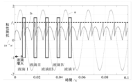
液体吐出ピペットチップ110の出口端112と液滴195との付着力の最大値f3に影響を与える要素は、液体吐出ピペットチップ110の表面自由エネルギー、幾何学的寸法及び第一の液体の表面張力が含まれる。液体吐出ピペットチップ110及び第一の液体が交換されない場合に、液体吐出ピペットチップ110の出口端112と液滴195との付着力の最大値f3が変化しない。第二の液体699の中を運動している時に受けられた液滴195の粘性抵抗f2に影響を与える要素は、第二の液体699の粘性係数η、液滴195の半径r及び液滴195の運動速度vが含まれる。第一の液体が均一な速度で液体吐出ピペットチップ110の出口端112から排出される際に、液滴195の半径rが、微小液滴199を生成する間隔時間により決められる。液滴195が液体吐出ピペットチップ110の出口端112から脱離されるまで液体吐出ピペットチップ110の出口端112と同期に運動しているため、運動制御機構130により液体吐出ピペットチップ110の出口端112の運動速度を正確に制御することができる。第二の液体699の粘性係数ηが液滴195を生成する工程にある範囲内に変化することがある。しかしながら、第二の液体699の粘性係数ηの変化範囲が極めて小さい。図12に示されるように、曲線aは、液体吐出ピペットチップ110の出口端112の変位を示し、曲線b及び曲線cが共に、第二の液体699の粘性係数ηが極めて小さい範囲で変化する時に、微小液滴199を生成する工程の曲線を示す。第二の液体699の粘性係数ηが極めて小さい範囲で変化する時に、微小液滴199を生成する時間間隔を変更することなく、極めて小さい範囲だけに微小液滴199を生成するタイミングを変更する。図12に示されるように、曲線b及び曲線cにより示される微小液滴199を生成する時間間隔は、いずれも半周期t/2であることから、生成された微小液滴199の体積の均一性を確保することができる。 The factors affecting the maximum value f3 of the adhesive force between the outlet end 112 of the liquid-dispensing pipette tip 110 and the droplet 195 are the surface free energy of the liquid-dispensing pipette tip 110, the geometrical dimensions, and the surface of the first liquid. Includes tension. If the liquid-dispensing pipette tip 110 and the first liquid are not exchanged, the maximum adhesion force f 3 between the outlet end 112 of the liquid-dispensing pipette tip 110 and the droplet 195 does not change. Factors affecting the viscous drag f 2 of the droplet 195 experienced while moving through the second liquid 699 are the viscosity coefficient η of the second liquid 699, the radius r of the droplet 195 and the droplet 195 motion velocities v are included. The radius r of the droplet 195 is determined by the interval time that produces the microdroplet 199 when the first liquid is ejected from the outlet end 112 of the liquid ejecting pipette tip 110 at a uniform velocity. The motion control mechanism 130 causes the exit end 112 of the liquid dispensing pipette tip 110 to move synchronously with the exit end 112 of the liquid dispensing pipette tip 110 until the droplet 195 is detached from the exit end 112 of the liquid dispensing pipette tip 110 . can be precisely controlled. The viscosity coefficient η of second liquid 699 may vary within a range in the process of producing droplet 195 . However, the variation range of the viscosity coefficient η of the second liquid 699 is extremely small. As shown in FIG. 12, curve a shows the displacement of the outlet end 112 of the liquid dispensing pipette tip 110, and curves b and c both vary over a very small range of the viscosity coefficient η of the second liquid 699. Occasionally, a curve for the process of generating microdroplets 199 is shown. When the viscosity coefficient η of the second liquid 699 changes within a very small range, the timing for generating the minute droplets 199 is changed only within a very small range without changing the time interval for generating the minute droplets 199 . As shown in FIG. 12, since the time intervals for generating the microdroplets 199 indicated by the curves b and c are both half periods t/2, the volume of the generated microdroplets 199 is uniform. can ensure the integrity of the

図13に示されるように、液体吐出ピペットチップ110が交換され、又は、第一の液体の表面張力が温度変化などにより変化した場合に、液体吐出ピペットチップ110の出口端112と液滴195との付着力の最大値f3を正確に制御することが難しくなる。従って、生成された微小液滴199の体積がある範囲でf3の変化に対して敏感にならないことは、寸法が均一な微小液滴199を生成することにとって重要な意味を持っている。図13に示されるように、曲線aが液体吐出ピペットチップ110の出口端112の変位を示し、曲線b及び曲線cが液体吐出ピペットチップ110が交換された時に微小液滴199の生成工程の曲線を示す。液体吐出ピペットチップ110が交換された後に、液体吐出ピペットチップ110の出口端112と液滴195との付着力の最大値f3がある範囲に波動することにより、液滴195が脱落される際に液体吐出ピペットチップ110の出口端112が異なる速度で運動するおそれがある。しかしながら、微小液滴199の生成が安定状態になっていると、液滴195が脱落される際に液体吐出ピペットチップ110の出口端112の速度が各揺動周期内に変化しない。図13に示されるように、曲線b及び曲線cにより示される微小液滴199の生成の時間間隔は、いずれも半周期t/2である。従って、微小液滴199を生成する間隔時間が変化しないことを確保することができる。第一の液体吐出液体吐出ピペットチップ110の出口端112の流速が変化しないと、生成された微小液滴199の体積が均一となる。それと同時に、第一の液体吐出液体吐出ピペットチップ110の出口端112の流速、及び、第二の液体699の中を揺動している液体吐出ピペットチップ110の出口端112の周波数を調整することができ、即ち、それと同時に、体積が均一な微小液滴199の体積及び生成の速さを制御することができる。 As shown in FIG. 13, when the liquid-dispensing pipette tip 110 is replaced or the surface tension of the first liquid changes due to a change in temperature or the like, the outlet end 112 of the liquid-dispensing pipette tip 110 and the droplet 195 are in contact with each other. It becomes difficult to accurately control the maximum value f3 of the adhesion force of . Therefore, the insensitivity of the volume of generated microdroplets 199 to changes in f 3 to some extent is critical to generating microdroplets 199 that are uniform in size. As shown in FIG. 13, curve a shows the displacement of the outlet end 112 of the liquid dispensing pipette tip 110, and curves b and c show the curves of the microdroplet 199 generation process when the liquid dispensing pipette tip 110 is replaced. indicates After the liquid-discharging pipette tip 110 is replaced, when the maximum value f3 of the adhesive force between the outlet end 112 of the liquid-discharging pipette tip 110 and the droplet 195 fluctuates within a certain range, the droplet 195 falls off. Alternatively, the outlet end 112 of the liquid dispensing pipette tip 110 may move at different velocities. However, if the generation of microdroplet 199 is at a steady state, the velocity of outlet end 112 of liquid dispensing pipette tip 110 does not change within each rocking period as droplet 195 is dropped. As shown in FIG. 13, the time intervals between the generation of microdroplets 199 indicated by curves b and c are both half period t/2. Therefore, it can be ensured that the interval time for generating microdroplets 199 does not change. If the flow velocity at the exit end 112 of the first liquid-ejecting liquid-ejecting pipette tip 110 does not change, the volume of the generated microdroplets 199 will be uniform. At the same time, adjusting the flow rate of the outlet end 112 of the first liquid-dispensing liquid-dispensing pipette tip 110 and the frequency of the outlet end 112 of the liquid-dispensing pipette tip 110 swinging through the second liquid 699. ie, at the same time, the volume and rate of generation of uniform volume microdroplets 199 can be controlled.

上記の実施例では、液体吐出ピペットチップ110の出口端112が正弦波状に変位する周期的な運動を行うと、付着力の最大値f3及び粘性抵抗f2の変化について、ある程度の許容性があり、即ち、付着力の最大値f3又は粘性抵抗f2がある範囲で変化する時に、依然として体積が均一な微小液滴199を生成することができる。液体吐出ピペットチップ110の出口端112が正弦波状に変位して周期的な運動を行う時に、体積が均一な微小液滴199の生成を確保できることを前提として、付着力の最大値f3を許容できる変化範囲を安定期として呼ぶ。安定期の存在は、液体吐出ピペットチップ110の加工及び微小液滴199の生成温度の制御にとって重要な意味を持っている。安定期の存在は、液体吐出ピペットチップ110の加工精度に対する要求をある程度まで低下させることが許可され、即ち、同じバッチで加工された液体吐出ピペットチップ110のそれぞれの表面自由エネルギーに相違が存在しても、体積が均一な微小液滴199を生成することができる。同様に、安定期の存在は、微小液滴199を生成する工程に温度制御に対する要求をある程度まで低下させることが許可される。 In the above embodiment, when the outlet end 112 of the liquid-dispensing pipette tip 110 undergoes a cyclical motion of sinusoidal displacement, there is some tolerance for changes in the maximum adhesion force f3 and the viscous resistance f2 . Yes, that is, microdroplets 199 with uniform volume can still be generated when the maximum value of the adhesive force f3 or the viscous drag f2 varies within a certain range. A maximum value of f3 for the adhesion force is allowed on the premise that it is possible to ensure the production of microdroplets 199 of uniform volume when the outlet end 112 of the liquid dispensing pipette tip 110 undergoes a sinusoidal displacement and periodic motion. The range of possible changes is called the stable period. The presence of the stable period has important implications for processing the liquid ejection pipette tip 110 and controlling the temperature at which the microdroplets 199 are generated. The existence of the plateau is allowed to reduce the demands on the processing accuracy of the liquid-dispensing pipette tips 110 to some extent, i.e., there is a difference in the surface free energy of each of the liquid-dispensing pipette tips 110 processed in the same batch. A microdroplet 199 having a uniform volume can be generated even if the volume is uniform. Similarly, the presence of a plateau allows the process of generating microdroplets 199 to reduce the temperature control requirements to some extent.

安定期の存在は、液体吐出ピペットチップ110の加工精度に対する要求又は微小液滴199生成工程の温度制御に対する要求を、ある程度まで低下させることが許可されることにより、さらに、微小液滴199の生成工程における消耗品としてのコスト及び制御用のコストを削減することができる。 The presence of the stable period allows the requirements for the processing accuracy of the liquid ejection pipette tip 110 or the requirements for temperature control in the microdroplet 199 generation process to be lowered to some extent, thereby further reducing the generation of the microdroplets 199. Costs for consumables in the process and costs for controls can be reduced.

上記の実施例では、液体吐出ピペットチップ110の出口端112が各運動周期に二つの微小液滴199を生成する。容易に理解され得るのは、液体吐出ピペットチップ110の出口端112が正弦波状に変位して周期的な運動を行う限り、液体吐出ピペットチップ110の出口端112の運動周期ごとに一つの微小液滴199を生成し、又は、二つの運動周期ごとに一つの微小液滴199を生成する時に、依然として付着力の最大値f3及び粘性抵抗f2の変化についてある程度の許容性を持ち、安定期が存在しているということである。 In the above example, the outlet end 112 of the liquid dispensing pipette tip 110 produces two microdroplets 199 in each motion cycle. It can be readily understood that one microliquid per cycle of movement of the outlet end 112 of the liquid dispensing pipette tip 110, as long as the outlet end 112 of the liquid dispensing pipette tip 110 undergoes a sinusoidal displacement and periodic motion. When generating droplets 199 or generating one microdroplet 199 every two motion cycles, there is still some tolerance for changes in the maximum adhesion force f3 and viscous resistance f2 , and the stability period exists.

微小液滴199の生成は、微小液滴199の重力及び慣性力からの影響がほぼ受けられない。従って、微小液滴199を生成する時には、液体吐出ピペットチップ110の出口端112が第二の液体699に任意方向に沿って正弦波状に変位して周期的な運動を行うことが可能である。液体吐出ピペットチップ110の出口端112の運動軌跡は、弧線、直線又は他の形状の軌跡であってもよい。 The generation of microdroplet 199 is substantially immune to the gravitational and inertial forces of microdroplet 199 . Therefore, when generating a microdroplet 199, the outlet end 112 of the liquid-discharging pipette tip 110 can be displaced sinusoidally along an arbitrary direction in the second liquid 699 to perform periodic motion. The motion trajectory of the outlet end 112 of the liquid dispensing pipette tip 110 may be an arcuate, straight line or other shaped trajectory.

図14(1)に示されるように、本出願の一実施例では、液体吐出ピペットチップ110を第二の液体699に傾斜して挿入し、液体吐出ピペットチップ110の出口端112を第二の液体699の液面下に揺動して微小液滴199を生成する。一つの実施可能な形態として、図14(2)に示されるように、液体吐出ピペットチップ110の出口端112が第二の液体699に水平の直線軌跡で、正弦波状に変位して周期的な運動を行い、微小液滴199を生成する。もう一つの実施可能な形態として、図14(3)に示されるように、液体吐出ピペットチップ110の出口端112が第二の液体699に垂直の直線軌跡で、正弦波状に変位して周期的な運動を行い、微小液滴199を生成する。 As shown in FIG. 14(1), in one embodiment of the present application, the liquid-dispensing pipette tip 110 is inserted obliquely into the second liquid 699, and the outlet end 112 of the liquid-dispensing pipette tip 110 is inserted into the second liquid. A microdroplet 199 is generated by rocking below the surface of the liquid 699 . In one possible embodiment, as shown in FIG. 14(2), the outlet end 112 of the liquid-dispensing pipette tip 110 is displaced sinusoidally in a horizontal linear trajectory in the second liquid 699, and periodically. Movement is performed to generate microdroplets 199 . As another possible embodiment, as shown in FIG. 14(3), the outlet end 112 of the liquid-dispensing pipette tip 110 is displaced sinusoidally in a linear trajectory perpendicular to the second liquid 699, and periodically displaced. motion to generate a microdroplet 199 .

図15に示されるように、本出願の他の一実施例では、ステップS213に、速度変化の一つの周期に、液体吐出ピペットチップ110の出口端112が周期の前半及び後半にいずれも、等変速運動を行う。さらに、ステップS213に、周期の前半及び後半に、液体吐出ピペットチップ110の出口端112の加速度が同じである。第一の液体を均一な流速で液体吐出ピペットチップ110の出口端112から排出するように制御する。第一の液体が連続して排出されるのに伴い、運動工程において受けられた液体吐出ピペットチップ110の出口端112に付着される液滴195の粘性抵抗f2も持続的に増加する。粘性抵抗f2が液滴195と液体吐出ピペットチップ110との付着力の最大値f3よりも大きい場合に、液滴195が液体吐出ピペットチップ110から脱離されて微小液滴199を形成する。そして、次の微小液滴199を生成する工程へ移行する。液体吐出ピペットチップ110の出口端112の運動周波数及び運動速度が第一の液体の流速に合致するように制御することにより、生成された微小液滴199の体積の均一性を確保することができる。 As shown in FIG. 15, in another embodiment of the present application, in step S213, for one period of velocity change, the exit end 112 of the liquid dispensing pipette tip 110 is adjusted to both the first and second halves of the period, and so on. Do shifting exercises. Further, in step S213, the acceleration of the exit end 112 of the liquid dispensing pipette tip 110 is the same in the first half and the second half of the cycle. The first liquid is controlled to exit the outlet end 112 of the liquid dispensing pipette tip 110 at a uniform flow rate. As the first liquid is continuously ejected, the viscous resistance f2 of the droplet 195 adhered to the outlet end 112 of the liquid-ejecting pipette tip 110 received in the movement process also increases continuously. When the viscous resistance f 2 is greater than the maximum adhesion force f 3 between the droplet 195 and the liquid ejection pipette tip 110 , the droplet 195 is detached from the liquid ejection pipette tip 110 to form a minute droplet 199 . . Then, the process proceeds to the step of generating the next minute droplet 199 . By controlling the motion frequency and motion speed of the exit end 112 of the liquid-dispensing pipette tip 110 to match the flow velocity of the first liquid, uniformity in the volume of the generated microdroplets 199 can be ensured. .

従来の液体吐出ピペットチップは、一般的に、直管状である。上記の直管状である液体吐出ピペットチップは、自体の延在方向に沿って出口端と近い一方端が急速に運動する際に、生成された微小液滴が破壊されてしまうことがある。生成された微小液滴の完全性を維持させるために、液体吐出ピペットチップに振動周波数を低下させることが必要となり、そして、微小液滴の生成の速さが低下してしまうことになる。 Conventional liquid dispensing pipette tips are generally straight tubular. In the straight tube-shaped liquid-discharging pipette tip, when one end near the outlet end moves rapidly along the extending direction of the tip, the generated minute droplets may be destroyed. In order to maintain the integrity of the generated microdroplets, it is necessary to lower the vibration frequency of the liquid dispensing pipette tip, which slows down the generation of the microdroplets.

このことに鑑み、従来の液体吐出ピペットチップが、生成された微小液滴の完全性、及び、微小液滴の生成の速さを両立できない課題について、生成された微小液滴の完全性、及び、微小液滴の生成の速さを両立できる液体吐出ピペットチップを提供するニーズがある。 In view of this, regarding the problem that conventional liquid ejection pipette tips cannot achieve both the integrity of generated microdroplets and the speed of generation of microdroplets, , there is a need to provide a liquid ejection pipette tip that can produce fine droplets at a high speed.

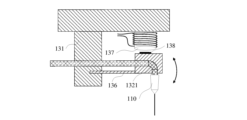
本出願に係る一つの実施例が提供する微小液滴199を生成するための液体吐出ピペットチップ110は、中空のキャビティを有する針軸113及び針軸113の一方端に配置される出口端112を含み、液体吐出ピペットチップ110の出口端112の端面の法線と針軸113の延在方向との夾角が90°以下である。液体吐出ピペットチップ110が管路本体の延在方向に沿って振動するときに、微小液滴199が液体吐出ピペットチップ110の出口端112から落下し、第二の液体699の粘性力及び液体吐出ピペットチップ110の出口端112の端面の押圧作用により、出口端112の運動軌跡から離れることから、微小液滴199が出口端112に破壊されてしまうことが避けられ、生成された微小液滴199に完全性が維持されると共に、液体吐出ピペットチップ110が管路本体の延在方向に急速に振動して微小液滴199を急速に生成することが可能となる。 One embodiment of the present application provides a liquid ejection pipette tip 110 for generating microdroplets 199, comprising a needle shaft 113 having a hollow cavity and an outlet end 112 disposed at one end of the needle shaft 113. Including, the included angle between the normal line of the end surface of the outlet end 112 of the liquid-dispensing pipette tip 110 and the extending direction of the needle shaft 113 is 90° or less. When the liquid-dispensing pipette tip 110 vibrates along the extension direction of the conduit body, the microdroplet 199 falls from the outlet end 112 of the liquid-dispensing pipette tip 110, and the viscous force of the second liquid 699 and the liquid ejection. Due to the pressing action of the end surface of the outlet end 112 of the pipette tip 110 , the minute droplets 199 are prevented from being broken by the outlet end 112 , since they are separated from the movement trajectory of the outlet end 112 . While the integrity is maintained, the liquid dispensing pipette tip 110 can vibrate rapidly in the direction of extension of the conduit body to rapidly generate microdroplets 199 .

図16に示されるように、一つの実施可能な形態として、液体吐出ピペットチップ110は、直管状であり、液体吐出ピペットチップ110の出口端112は、斜めカット構造である。液体吐出ピペットチップ110の出口端112を斜めカットすると、生成された微小液滴199の完全性及び微小液滴199の生成効率を両立できると共に、構造が簡単になり、容易に実現可能であり、制造のコストが低く、多量で加工される際に精度が高いという利点が存在している。さらに、液体吐出ピペットチップ110の出口端112の端面の法線と針軸113の延在方向との夾角が15°-75°にあるようにすれば、実際の状況に応じて、液体吐出ピペットチップ110の出口端112の端面の法線と針軸113の延在方向との夾角を設置してもよい。微小液滴199の生成に影響が与えられず、又は、微小液滴199が破壊されないように、液体吐出ピペットチップ110の出口端112の端面の法線と針軸113の延在方向との夾角が大きすぎたり小さすぎたりすることが好ましくない。さらに、液体吐出ピペットチップ110の出口端112の端面の法線と針軸113の延在方向との夾角が30°-60°である。具体的には、液体吐出ピペットチップ110の出口端112の端面の法線と針軸113の延在方向との夾角が45°である。45°の夾角とすれば、順調に微小液滴199を生成するのを確保することができるだけでなく、生成された微小液滴199を効果的に出口端112の運動軌跡から押し出し、生成された微小液滴199が液体吐出ピペットチップ110の出口端112により破壊されてしまうことを避けることができる。 As shown in FIG. 16, in one possible form, the liquid-dispensing pipette tip 110 has a straight tubular shape, and the outlet end 112 of the liquid-dispensing pipette tip 110 has an oblique cut structure. By obliquely cutting the outlet end 112 of the liquid ejection pipette tip 110, the integrity of the generated microdroplets 199 and the generation efficiency of the microdroplets 199 can both be achieved, and the structure is simple and can be easily realized. It has the advantages of low manufacturing cost and high precision when processed in large quantities. Furthermore, if the included angle between the normal to the end face of the outlet end 112 of the liquid-dispensing pipette tip 110 and the extending direction of the needle shaft 113 is between 15° and 75°, the liquid-dispensing pipette can be adjusted according to the actual situation. An included angle between the normal line of the end face of the outlet end 112 of the tip 110 and the extending direction of the needle shaft 113 may be set. The included angle between the normal line of the end face of the outlet end 112 of the liquid ejection pipette tip 110 and the extending direction of the needle shaft 113 is such that the generation of the microdroplets 199 is not affected or the microdroplets 199 are not destroyed. too large or too small is undesirable. Further, the included angle between the normal to the end face of outlet end 112 of liquid-discharging pipette tip 110 and the extending direction of needle shaft 113 is 30°-60°. Specifically, the included angle between the normal to the end face of outlet end 112 of liquid-dispensing pipette tip 110 and the extending direction of needle shaft 113 is 45°. With an included angle of 45°, it not only ensures that the microdroplets 199 are generated smoothly, but also effectively pushes the generated microdroplets 199 out of the motion trajectory of the exit end 112, and the generated microdroplets 199 It is possible to avoid breaking the microdroplets 199 by the exit end 112 of the liquid ejection pipette tip 110 .

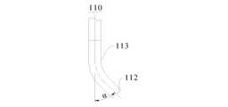
図17に示されるように、他の一つの実施可能な形態として、液体吐出ピペットチップ110の出口端112と近い針軸113の部分に折り曲げの構造が含まれる。液体吐出ピペットチップ110の出口端112を折り曲げることにより、生成された微小液滴199の完全性及び微小液滴199の生成効率を両立することができると共に、構造が簡単になり、容易に実現でき、制造のコストが低く、多量で加工される精度が高いという利点が存在している。さらに、液体吐出ピペットチップ110の出口端112の端面の法線と針軸113の延在方向との夾角が15°-75°である。実際の状況に応じて、液体吐出ピペットチップ110の出口端112の端面の法線と針軸113の延在方向との夾角を設置してもよい。微小液滴199の生成に影響が与えられず、又は、微小液滴199が破壊されないように、液体吐出ピペットチップ110の出口端112の端面の法線と針軸113の延在方向との夾角が大きすぎたり小さすぎたりすることが好ましくない。さらに、液体吐出ピペットチップ110の出口端112の端面の法線と針軸113の延在方向との夾角が30°-60°である。具体的には、液体吐出ピペットチップ110の出口端112の端面の法線と針軸113の延在方向との夾角が45°である。45°の夾角とすれば、順調に微小液滴199を生成するのを確保することができるだけでなく、生成された微小液滴199を効果的に出口端112の運動軌跡から押し出し、生成された微小液滴199が液体吐出ピペットチップ110の出口端112により破壊されてしまうことを避けることができる。 As shown in FIG. 17, another possible configuration includes a bent structure on the portion of needle shaft 113 near outlet end 112 of liquid dispensing pipette tip 110 . By bending the outlet end 112 of the liquid-discharging pipette tip 110, it is possible to achieve both the integrity of the generated microdroplets 199 and the generation efficiency of the microdroplets 199, and the structure is simple and can be easily realized. , there are advantages of low manufacturing cost and high precision in mass processing. Furthermore, the included angle between the normal to the end face of the outlet end 112 of the liquid-dispensing pipette tip 110 and the extending direction of the needle shaft 113 is 15°-75°. The included angle between the normal line of the end surface of the outlet end 112 of the liquid-dispensing pipette tip 110 and the extending direction of the needle shaft 113 may be set according to the actual situation. The included angle between the normal line of the end face of the outlet end 112 of the liquid ejection pipette tip 110 and the extending direction of the needle shaft 113 is such that the generation of the microdroplets 199 is not affected or the microdroplets 199 are not destroyed. too large or too small is undesirable. Further, the included angle between the normal to the end face of outlet end 112 of liquid-discharging pipette tip 110 and the extending direction of needle shaft 113 is 30°-60°. Specifically, the included angle between the normal to the end face of outlet end 112 of liquid-dispensing pipette tip 110 and the extending direction of needle shaft 113 is 45°. With an included angle of 45°, it not only ensures that the microdroplets 199 are generated smoothly, but also effectively pushes the generated microdroplets 199 out of the motion trajectory of the exit end 112, and the generated microdroplets 199 It is possible to avoid breaking the microdroplets 199 by the exit end 112 of the liquid ejection pipette tip 110 .

好ましくは、液体吐出ピペットチップ110の出口端112と近い針軸113の折り曲げ構造は、折れ線セグメント、円弧セグメント、滑らかな曲線セグメント、直線セグメントなどのうちの一つ又は組み合わせを有する。図17に示されるように、本実施例では、液体吐出ピペットチップ110の出口端112と近い針軸113の部分は、遷移する円弧セグメントを有し、具体的に、円弧セグメントと直線セグメントとの組み合わせを有する。直管状とされる液体吐出ピペットチップ110は、加工中に所定角度だけ円弧状に曲げればよく、加工され易い。 Preferably, the bent structure of the needle shaft 113 near the outlet end 112 of the liquid dispensing pipette tip 110 has one or a combination of broken line segments, circular arc segments, smooth curved segments, straight segments, and the like. As shown in FIG. 17, in this embodiment, the portion of needle shaft 113 near outlet end 112 of liquid dispensing pipette tip 110 has transitional arc segments, specifically, arc segments and straight segments. have a combination. The liquid-dispensing pipette tip 110, which has a straight tubular shape, can be easily processed by bending it into an arc shape by a predetermined angle during processing.

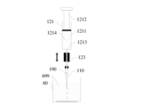
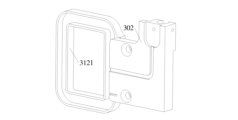
図18及び図19に示されるように、本出願に係る一実施例が提供する液体吐出ピペットチップ110は、針ハブ114の延在方向に沿って針ハブ114を貫通する液体リザーバ115を有する針ハブ114を含む。液体リザーバ115は、一方端が液体吐出ピペットチップ110の出口端112から離れる針軸113の一方端に連通され、針ハブ114における針軸113から離れる一方端が液体吐出ピペットチップ110の入口端111である。針ハブ114は、針軸113に固定接続される。微小液滴199を生成するための第一の液体は、針ハブ114内に貯留されておいてもよい。そして、微小液滴199を連続的かつ多量に生成することが可能である。さらに、針ハブ114における針軸113から離れる一方端の内面に係止溝116が設けられる。この係止溝116により、流体駆動機構120と着脱可能な接続が可能となり、液体吐出ピペットチップ110を便宜に交換することができる。 As shown in FIGS. 18 and 19, a liquid dispensing pipette tip 110 provided by one embodiment of the present application includes a needle having a liquid reservoir 115 penetrating the needle hub 114 along the direction in which the needle hub 114 extends. Includes hub 114 . One end of liquid reservoir 115 communicates with one end of needle shaft 113 that is remote from outlet end 112 of liquid-dispensing pipette tip 110 , and one end that is remote from needle shaft 113 in needle hub 114 is connected to inlet end 111 of liquid-dispensing pipette tip 110 . is. Needle hub 114 is fixedly connected to needle shaft 113 . A first liquid for generating microdroplets 199 may be stored in needle hub 114 . Then, it is possible to generate a large number of minute droplets 199 continuously. Furthermore, locking groove 116 is provided on the inner surface of one end of needle hub 114 away from needle shaft 113 . The locking groove 116 enables detachable connection with the fluid drive mechanism 120, and the liquid discharge pipette tip 110 can be conveniently replaced.

本出願が提供する微小液滴199生成装置は、第二の液体699の液面下に微小液滴199を生成するために用いられる。微小液滴199生成装置は、流体駆動機構120、運動制御機構130及び上記態様のいずれか一つに記載の液体吐出ピペットチップ110を含む。液体吐出ピペットチップ110の内部には第一の液体が貯留されており、液体吐出ピペットチップ110は、出口端112及び入口端111を有する。流体駆動機構120は、液体吐出ピペットチップ110の入口端111に接続され、液体吐出ピペットチップ110の内部に貯留される第一の液体を液体吐出ピペットチップ110の出口端112から排出するために用いられる。運動制御機構130は、液体吐出ピペットチップ110の出口端112が第二の液体699の液面下に、所定軌跡、所定速度又は所定加速度で運動を行い、液体吐出ピペットチップ110の出口端112から排出される第一の液体が表面張力及び付着力に打ち勝ち、第二の液体699に微小液滴199を形成するように制御するために用いられる。 The microdroplet 199 generator provided by the present application is used to generate microdroplets 199 below the surface of the second liquid 699 . The microdroplet 199 generator includes a fluid drive mechanism 120, a motion control mechanism 130 and a liquid dispensing pipette tip 110 according to any one of the above aspects. A first liquid is stored inside the liquid-dispensing pipette tip 110 , and the liquid-dispensing pipette tip 110 has an outlet end 112 and an inlet end 111 . The fluid driving mechanism 120 is connected to the inlet end 111 of the liquid-dispensing pipette tip 110 and used to eject the first liquid stored inside the liquid-dispensing pipette tip 110 from the outlet end 112 of the liquid-dispensing pipette tip 110 . be done. The motion control mechanism 130 causes the outlet end 112 of the liquid-dispensing pipette tip 110 to move below the surface of the second liquid 699 at a predetermined trajectory, a predetermined speed, or a predetermined acceleration, thereby causing the outlet end 112 of the liquid-dispensing pipette tip 110 to move. It is used to control the ejected first liquid to overcome surface tension and adhesion forces to form microdroplets 199 in the second liquid 699 .

本出願が提供する液体吐出ピペットチップ110は、第二の液体699の液面下に運動工程において微小液滴199を生成する。一つの実施可能な形態として、液体吐出ピペットチップ110の出口端112は、第二の液体699の液面下に方形波状的に変化する速度で運動を行うことができ、ただし、その加速度をa1とする。第一の液体は、液体吐出ピペットチップ110の出口端112から排出されると、液体吐出ピペットチップ110の出口端112に付着される液滴195を形成する。液滴195は、液体吐出ピペットチップ110の出口端112が瞬間加速度運動を行う瞬間に、液体吐出ピペットチップ110の出口端112から脱離され、微小液滴199を形成する。図3に示されるように、液体吐出ピペットチップ110の出口端112から脱離されるまで受けられた微小液滴199の作用力は、それぞれ、重力G、第二の液体699の浮力f1、第二の液体699の粘性抵抗f2及び液体吐出ピペットチップ110の出口端112と液滴195との最大の付着力f3である。微小液滴199について、液体吐出ピペットチップ110の出口端112から脱離されるまでその質量をmとし、その加速度をa2とすると、ニュートン運動の第二法則によれば、

Figure 0007220366000006
が得られる。 The liquid dispensing pipette tip 110 provided by the present application produces microdroplets 199 in a motion step below the surface of the second liquid 699 . In one possible embodiment, the outlet end 112 of the liquid dispensing pipette tip 110 can move with a square wave-like velocity below the surface of the second liquid 699, where the acceleration is a 1 . The first liquid forms a droplet 195 that adheres to the outlet end 112 of the liquid dispensing pipette tip 110 as it is expelled from the outlet end 112 of the liquid dispensing pipette tip 110 . Droplet 195 is detached from exit end 112 of liquid discharge pipette tip 110 to form microdroplet 199 at the moment exit end 112 of liquid discharge pipette tip 110 undergoes a momentary acceleration motion. As shown in FIG. 3, the forces acting on the microdroplet 199 received until it detached from the outlet end 112 of the liquid dispensing pipette tip 110 are respectively the gravity force G, the buoyancy force f 1 of the second liquid 699, and the The second is the viscous drag f 2 of the liquid 699 and the maximum adhesion force f 3 between the exit end 112 of the liquid dispensing pipette tip 110 and the droplet 195 . Assuming that the mass of the microdroplet 199 until it is detached from the exit end 112 of the liquid dispensing pipette tip 110 is m, and the acceleration is a2 , according to Newton's second law of motion,
Figure 0007220366000006
is obtained.

液体吐出ピペットチップ110の出口端112と液滴195との付着力の最大値f3は、液体吐出ピペットチップ110の表面自由エネルギー、液滴195の表面張力及び液体吐出ピペットチップ110の幾何学的寸法に関連されている。液体吐出ピペットチップ110の出口端112が瞬間加速度運動を行う時に、液滴195に対する液体吐出ピペットチップ110の出口端112の付着力の方向と加速度の方向は同じである。液体吐出ピペットチップ110の出口端112に付着された液滴195を球状として簡略化する。ストークス(Stokes)の式によると、わかるように、第二の液体699の中を運動している時に受けられた液滴195の粘性抵抗がf2=6πηrvとなり、そのうち、ηが第二の液体699の粘性係数であり、rが液滴195の半径であり、vが液滴195の運動速度である。液体吐出ピペットチップ110の出口端112が瞬間加速度運動を行うまで、液滴195の速度がゼロであることから、液体吐出ピペットチップ110の出口端112が瞬間加速度運動を行う瞬間に、第二の液体699に受けられた液滴195の粘性抵抗f2がゼロ又は極めて小さい。微小液滴199を生成する工程では、一般的に、液滴195の直径範囲がピコリットルからマイクロリットルまでのオーダーであり、液滴195の重力Gと第二の液体699の浮力f1とは、それらの方向が反対であることから、液滴195の重力Gと第二の液体699の浮力f1とのベクトルの和がほぼゼロになる。

Figure 0007220366000007
The maximum value f 3 of the adhesive force between the exit end 112 of the liquid ejection pipette tip 110 and the droplet 195 is determined by the surface free energy of the liquid ejection pipette tip 110 , the surface tension of the droplet 195 and the geometry of the liquid ejection pipette tip 110 . related to dimensions. When the outlet end 112 of the liquid-dispensing pipette tip 110 performs an instantaneous acceleration motion, the direction of the adhesive force of the outlet end 112 of the liquid-dispensing pipette tip 110 to the droplet 195 is the same as the direction of the acceleration. Droplet 195 attached to exit end 112 of liquid dispensing pipette tip 110 is simplified as being spherical. According to the Stokes equation, it can be seen that the viscous drag experienced by the droplet 195 in motion in the second liquid 699 is f 2 =6πηrv, where η is the second liquid is the viscosity coefficient of 699, r is the radius of droplet 195, and v is the velocity of motion of droplet 195. Since the velocity of the droplet 195 is zero until the outlet end 112 of the liquid dispensing pipette tip 110 undergoes the instantaneous acceleration motion, the moment the outlet end 112 of the liquid dispensing pipette tip 110 performs the instantaneous acceleration motion, the second The viscous resistance f2 of the droplet 195 received by the liquid 699 is zero or very small. In the process of generating microdroplets 199, typically the diameter range of droplets 195 is on the order of picoliters to microliters, and the gravitational force G of droplets 195 and the buoyant force f of second liquid 699 are , their directions are opposite, so that the vector sum of the gravity G of the droplet 195 and the buoyant force f 1 of the second liquid 699 is approximately zero.
Figure 0007220366000007

運動制御機構130の連動によれば、液体吐出ピペットチップ110の出口端112の瞬間加速度を正確に制御することができる。そして、液体吐出ピペットチップ110の出口端112について各瞬間で加速度を比較的大きくする制御することができれば、液体吐出ピペットチップ110の出口端112が瞬間加速度運動を行うと、液滴195を効果的に生成することができる。液体吐出ピペットチップ110の出口端112は、一つの運動周期に、一つ又は二つ以上の微小液滴199を形成することが好ましい。 Coupling the motion control mechanism 130 allows for precise control of the instantaneous acceleration of the outlet end 112 of the liquid dispensing pipette tip 110 . Then, if the acceleration at the outlet end 112 of the liquid dispensing pipette tip 110 can be controlled to be relatively large at each moment, the droplet 195 can be effectively ejected when the outlet end 112 of the liquid dispensing pipette tip 110 performs an instantaneous acceleration motion. can be generated to Outlet end 112 of liquid dispensing pipette tip 110 preferably forms one or more microdroplets 199 in one motion cycle.

図20に示されるように、本出願に係る一実施例では、液体吐出ピペットチップ110の出口端112の端面の法線と管路本体の延在方向との夾角が45°であり、液体吐出ピペットチップ110の出口端112が斜めカットの構造である。第二の液体699の液面が上向きであり、液体吐出ピペットチップ110が垂直して設置される。液体吐出ピペットチップ110の出口端112は、第二の液体699の液面下に、垂直線セグメントの軌跡に沿って、方形波状に変化する速度で、運動を行う。液体吐出ピペットチップ110の出口端112は、一つの運動周期に、一つの微小液滴199を生成する。液体吐出ピペットチップ110に、第一の液体が貯留されている。流体駆動機構120は、液体吐出ピペットチップ110が液体吐出ピペットチップ110の各運動周期に出口端112から等体積の第一の液体を排出するように制御する。液体吐出ピペットチップ110の出口端112に付着される液滴195が所定体積になると、液体吐出ピペットチップ110の出口端112は、上限界の位置からa1という大きさの加速度で下向きに瞬間加速度運動を行いながら、液体吐出ピペットチップ110の出口端112に付着される液滴195を液体吐出ピペットチップ110の出口端112から脱離して微小液滴199を形成する。第二の液体699の粘性力、及び、液体吐出ピペットチップ110の出口端112の端面の押圧作用により、微小液滴199が出口端112の運動軌跡から離れて液体吐出ピペットチップ110の側壁に近接する。液体吐出ピペットチップ110の出口端112が持続的に下向きに運動しながら、第一の液体を依然として液体吐出ピペットチップ110の出口端112から排出して液体吐出ピペットチップ110の出口端112に付着される液滴195を形成する。液体吐出ピペットチップ110の出口端112が下限界の位置まで運動すると、液体吐出ピペットチップ110の出口端112が下限界の位置から上向きに運動する。液体吐出ピペットチップ110の出口端112が下限界の位置から上向き運動する工程では、第一の液体を依然として液体吐出ピペットチップ110の出口端112から排出し、液体吐出ピペットチップ110の出口端112に付着される液滴195の体積が増大する。液体吐出ピペットチップ110の出口端112が上限界の位置まで運動すると、液体吐出ピペットチップ110の出口端112に付着される液滴195の体積が、前回に脱落された微小液滴199の体積と等しい。液体吐出ピペットチップ110の出口端112が再度、上限界の位置からa1という大きさの加速度で下向きに瞬間加速度運動をして新たな微小液滴199を形成する。このように繰り返す。 As shown in FIG. 20, in one embodiment according to the present application, the included angle between the normal to the end face of the outlet end 112 of the liquid-ejecting pipette tip 110 and the extending direction of the conduit body is 45°, and the liquid ejection is The outlet end 112 of the pipette tip 110 is of beveled construction. The liquid surface of the second liquid 699 faces upward, and the liquid discharge pipette tip 110 is installed vertically. The outlet end 112 of the liquid-dispensing pipette tip 110 moves below the surface of the second liquid 699 along the trajectory of the vertical line segment with a square-wave varying velocity. Outlet end 112 of liquid dispensing pipette tip 110 produces one microdroplet 199 in one motion cycle. A first liquid is stored in the liquid ejection pipette tip 110 . The fluid drive mechanism 120 controls the liquid dispensing pipette tip 110 to eject an equal volume of the first liquid from the outlet end 112 during each cycle of movement of the liquid dispensing pipette tip 110 . When the droplet 195 adhering to the outlet end 112 of the liquid-dispensing pipette tip 110 reaches a predetermined volume, the outlet end 112 of the liquid-dispensing pipette tip 110 instantaneously accelerates downward from the upper limit position with an acceleration of magnitude a1 . While moving, droplets 195 attached to the outlet end 112 of the liquid-dispensing pipette tip 110 are detached from the outlet end 112 of the liquid-dispensing pipette tip 110 to form minute droplets 199 . Due to the viscous force of the second liquid 699 and the pressing action of the end surface of the outlet end 112 of the liquid ejection pipette tip 110 , the microdroplet 199 moves away from the motion trajectory of the outlet end 112 and approaches the side wall of the liquid ejection pipette tip 110 . do. While the outlet end 112 of the liquid-dispensing pipette tip 110 continues to move downward, the first liquid is still ejected from the outlet end 112 of the liquid-dispensing pipette tip 110 and adheres to the outlet end 112 of the liquid-dispensing pipette tip 110 . A droplet 195 is formed. As the exit end 112 of the liquid dispensing pipette tip 110 moves to the lower limit position, the exit end 112 of the liquid dispensing pipette tip 110 moves upward from the lower limit position. In the step in which outlet end 112 of liquid-dispensing pipette tip 110 moves upward from the lower limit position, the first liquid is still expelled from outlet end 112 of liquid-dispensing pipette tip 110 and into outlet end 112 of liquid-dispensing pipette tip 110. The volume of deposited droplet 195 increases. When the outlet end 112 of the liquid-dispensing pipette tip 110 is moved to the upper limit position, the volume of the droplet 195 adhering to the outlet end 112 of the liquid-dispensing pipette tip 110 is equal to the volume of the microdroplet 199 that was previously dropped. equal. The exit end 112 of the liquid dispensing pipette tip 110 again undergoes a momentary downward acceleration motion from the upper limit position with an acceleration of magnitude a 1 to form a new microdroplet 199 . Repeat like this.

図21に示されるように、本出願に係る一実施例では、液体吐出ピペットチップ110の出口端112の端面の法線と管路本体の延在方向との夾角が45°であり、液体吐出ピペットチップ110の出口端112が斜めカットの構造である。第二の液体699の液面が上向きであり、液体吐出ピペットチップ110が垂直して設置される。液体吐出ピペットチップ110の出口端112は、第二の液体699の液面下に、垂直線セグメントの軌跡に沿って、方形波状に変化する速度で運動を行う。液体吐出ピペットチップ110の出口端112は、一つの運動周期に、二つの微小液滴199を生成する。液体吐出ピペットチップ110に、第一の液体が貯留されている。流体駆動機構120は、第一の液体が均一な流速で出口端112から排出されるように制御する。液体吐出ピペットチップ110の出口端112に付着される液滴195が所定体積になると、液体吐出ピペットチップ110の出口端112が上限界の位置からa1という大きさの加速度で下向きに瞬間加速度運動を行いながら、液体吐出ピペットチップ110の出口端112に付着される液滴195を液体吐出ピペットチップ110の出口端112から脱離し、微小液滴199を形成する。第二の液体699の粘性力及び液体吐出ピペットチップ110の出口端112の端面の押圧作用により、微小液滴199が出口端112の運動軌跡から離れ、液体吐出ピペットチップ110の側壁に近接する。液体吐出ピペットチップ110の出口端112が継続して下向きに運動を行いながら、第一の液体を依然として液体吐出ピペットチップ110の出口端112から排出し、液体吐出ピペットチップ110の出口端112に付着される液滴195を形成し、液体吐出ピペットチップ110の出口端112に付着される液滴195の体積が増大する。 As shown in FIG. 21, in one embodiment according to the present application, the included angle between the normal to the end surface of the outlet end 112 of the liquid-discharging pipette tip 110 and the extending direction of the conduit body is 45°, and the liquid-discharging The outlet end 112 of the pipette tip 110 is of beveled construction. The liquid surface of the second liquid 699 faces upward, and the liquid discharge pipette tip 110 is installed vertically. The outlet end 112 of the liquid-dispensing pipette tip 110 moves under the surface of the second liquid 699 along the trajectory of the vertical line segment with a square wave-like varying velocity. Outlet end 112 of liquid dispensing pipette tip 110 produces two microdroplets 199 in one motion cycle. A first liquid is stored in the liquid ejection pipette tip 110 . Fluid drive mechanism 120 controls the first liquid to exit outlet end 112 at a uniform flow rate. When the droplet 195 adhering to the outlet end 112 of the liquid-dispensing pipette tip 110 reaches a predetermined volume, the outlet end 112 of the liquid-dispensing pipette tip 110 instantaneously accelerates downward from the upper limit position with an acceleration of a1 . , droplets 195 adhering to the outlet end 112 of the liquid-discharging pipette tip 110 are detached from the outlet end 112 of the liquid-discharging pipette tip 110 to form minute droplets 199 . Due to the viscous force of the second liquid 699 and the pressing action of the end face of the outlet end 112 of the liquid ejection pipette tip 110 , the microdroplet 199 leaves the motion trajectory of the outlet end 112 and approaches the side wall of the liquid ejection pipette tip 110 . As the outlet end 112 of the liquid-dispensing pipette tip 110 continues to move downward, the first liquid is still expelled from the outlet end 112 of the liquid-dispensing pipette tip 110 and adheres to the outlet end 112 of the liquid-dispensing pipette tip 110 . The volume of the droplet 195 that adheres to the exit end 112 of the liquid dispensing pipette tip 110 increases.

液体吐出ピペットチップ110の出口端112が下限界の位置まで運動するときに、液体吐出ピペットチップ110の出口端112に付着された液滴195の体積が前回に脱落された微小液滴199の体積と等しい。液体吐出ピペットチップ110の出口端112が下限界の位置からa1という大きさの加速度で上向きに瞬間加速度運動を行うと、出口端112に付着される液滴195が出口端112から脱離され、新たな微小液滴199を形成する。液体吐出ピペットチップ110の出口端112が下限界に位置する時に生成された微小液滴199は、出口端112の付着力の作用により、小さい距離だけ上向きに運動してから、第二の液体699により次第に落下していく。液体吐出ピペットチップ110の出口端112が下限界に位置すると上向きに運動する工程では、第一の液体が依然として液体吐出ピペットチップ110の出口端112から排出され、液体吐出ピペットチップ110の出口端112に付着された液滴195の体積が増大する。液体吐出ピペットチップ110の出口端112が上限界の位置まで運動すると、液体吐出ピペットチップ110の出口端112に付着される液滴195の体積が前回に脱落された微小液滴199の体積と等しい。液体吐出ピペットチップ110の出口端112が再度、上限界の位置からa1という大きさの加速度で下向きに瞬間加速度運動を行い、新たな微小液滴199を形成する。このように繰り返す。液体吐出ピペットチップ110の出口端112が再度、上限界の位置から下向きに運動している時に、出口端112の直下の軌跡範囲に依然として微小液滴199が存在している場合に、生成された微小液滴199は、出口端112に付着される液滴195に衝突されると、出口端112の端面の法線に沿って運動して出口端112の運動軌跡から離れる。 When the outlet end 112 of the liquid-dispensing pipette tip 110 moves to the lower limit position, the volume of the droplet 195 adhered to the outlet end 112 of the liquid-dispensing pipette tip 110 is equal to the volume of the previously dropped microdroplet 199. is equal to When the outlet end 112 of the liquid-discharging pipette tip 110 performs an upward instantaneous acceleration motion with an acceleration of a1 from the lower limit position, the droplet 195 adhering to the outlet end 112 is detached from the outlet end 112. , forming a new microdroplet 199 . A microdroplet 199 produced when the outlet end 112 of the liquid dispensing pipette tip 110 is at its lower limit moves upward a small distance due to the action of the adhesive force of the outlet end 112 before being ejected by the second liquid 699 . It will gradually fall. In the process of moving upward once the outlet end 112 of the liquid dispensing pipette tip 110 is at the lower limit, the first liquid is still expelled from the outlet end 112 of the liquid dispensing pipette tip 110 and exits the outlet end 112 of the liquid dispensing pipette tip 110 . The volume of droplet 195 attached to increases. When the outlet end 112 of the liquid dispensing pipette tip 110 moves to the upper limit position, the volume of the droplet 195 attached to the outlet end 112 of the liquid dispensing pipette tip 110 is equal to the volume of the previously dropped microdroplet 199 . . The exit end 112 of the liquid dispensing pipette tip 110 again undergoes a momentary acceleration motion downward from the upper limit position with an acceleration of magnitude a 1 to form a new microdroplet 199 . Repeat like this. When the outlet end 112 of the liquid dispensing pipette tip 110 is again moving downward from the upper limit position, the microdroplet 199 is still present in the trajectory area immediately below the outlet end 112. When the microdroplet 199 collides with the droplet 195 attached to the outlet end 112 , the microdroplet 199 moves along the normal line of the end face of the outlet end 112 and leaves the motion trajectory of the outlet end 112 .

本出願が提供する液体吐出ピペットチップ110は、第二の液体699の液面下に運動を行う工程に、微小液滴199を生成する。他の一つの実施可能な形態として、液体吐出ピペットチップ110の出口端112は、第二の液体699の液面下に正弦波状に変位して運動を行う。第一の液体は、液体吐出ピペットチップ110の出口端112から排出され、液体吐出ピペットチップ110の出口端112に付着される液滴195を形成する。液滴195は、液体吐出ピペットチップ110の出口端112の運動速度が一定の程度になると、液体吐出ピペットチップ110の出口端112から脱離され、微小液滴199を形成する。図6に示されるように、液体吐出ピペットチップ110の出口端112から脱離されるまで受けられた微小液滴199の作用力は、それぞれ、重力G、第二の液体699の浮力f1、第二の液体699の粘性抵抗f1及び液体吐出ピペットチップ110の出口端112と液滴195との最大の付着力f3である。微小液滴199について、液体吐出ピペットチップ110の出口端112から脱離されるまでその質量をmとし、速度をvとし、加速度をa2とすると、液滴195は、第二の液体699の中を運動している工程において、粘性力f2、重力G、浮力f1及び付着力f3による相乗効果により受けられており、即ち、

Figure 0007220366000008
The liquid dispensing pipette tip 110 provided by the present application produces microdroplets 199 during the process of moving below the surface of the second liquid 699 . In another possible embodiment, the outlet end 112 of the liquid-dispensing pipette tip 110 is displaced sinusoidally below the surface of the second liquid 699 for motion. The first liquid is expelled from the outlet end 112 of the liquid dispensing pipette tip 110 and forms a droplet 195 that adheres to the outlet end 112 of the liquid dispensing pipette tip 110 . Droplet 195 is detached from outlet end 112 of liquid ejecting pipette tip 110 to form microdroplet 199 when outlet end 112 of liquid ejecting pipette tip 110 moves at a certain rate. As shown in FIG. 6, the forces acting on the microdroplet 199 received until it detached from the outlet end 112 of the liquid-dispensing pipette tip 110 are respectively the gravity force G, the buoyancy force f 1 of the second liquid 699, and the The second is the viscous drag f 1 of the liquid 699 and the maximum adhesion force f 3 between the outlet end 112 of the liquid dispensing pipette tip 110 and the droplet 195 . Assuming that the mass of the microdroplet 199 is m, the velocity is v, and the acceleration is a2 until it is detached from the outlet end 112 of the liquid-dispensing pipette tip 110, the droplet 195 moves into the second liquid 699. is subjected to a synergistic effect by the viscous force f 2 , the gravitational force G, the buoyant force f 1 and the adhesive force f 3 , i.e.
Figure 0007220366000008

液体吐出ピペットチップ110の出口端112と液滴195との付着力の最大値f3は、液体吐出ピペットチップ110の表面自由エネルギー、液滴195の表面張力及び液体吐出ピペットチップ110の幾何学的寸法に関連されている。液体吐出ピペットチップ110の出口端112に付着された液滴195を球状として簡略化する。ストークス(Stokes)の式によると、わかるように、第二の液体699の中を運動している時に受けられた液滴195の粘性抵抗がf2=6πηrvとなり、そのうち、ηが第二の液体699の粘性係数であり、rが液滴195の半径であり、vが液滴195の運動速度である。微小液滴199を生成する工程において、一般的に、液滴195の直径範囲は、ピコリットルからマイクロリットルまでのオーダーであり、第二の液体699の粘性係数は、一般的に、比較的大きい。

Figure 0007220366000009
The maximum value f 3 of the adhesive force between the exit end 112 of the liquid ejection pipette tip 110 and the droplet 195 is determined by the surface free energy of the liquid ejection pipette tip 110 , the surface tension of the droplet 195 and the geometry of the liquid ejection pipette tip 110 . related to dimensions. Droplet 195 attached to exit end 112 of liquid dispensing pipette tip 110 is simplified as being spherical. According to the Stokes equation, it can be seen that the viscous drag experienced by the droplet 195 in motion in the second liquid 699 is f 2 =6πηrv, where η is the second liquid is the viscosity coefficient of 699, r is the radius of droplet 195, and v is the velocity of motion of droplet 195. In the process of generating microdroplets 199, typically the diameter range of droplets 195 is on the order of picoliters to microliters, and the viscosity coefficient of second liquid 699 is typically relatively large. .
Figure 0007220366000009

図22に示されるように、本出願に係る一実施例では、液体吐出ピペットチップ110の出口端112の端面の法線と管路本体の延在方向との夾角が45°であり、液体吐出ピペットチップ110の出口端112と近い針軸113の部分が折り曲げの構造である。第二の液体699の液面が上向きであり、液体吐出ピペットチップ110が垂直して設置される。液体吐出ピペットチップ110の出口端112が第二の液体699の液面下に垂直線セグメントの軌跡に沿って、正弦波状に変位して運動を行う。液体吐出ピペットチップ110の出口端112は、一つの運動周期に、一つの微小液滴199を生成する。液体吐出ピペットチップ110に第一の液体が貯留されている。流体駆動機構120は、制御液体吐出ピペットチップ110が液体吐出ピペットチップ110の各運動周期に出口端112から等体積の第一の液体を排出するように制御する。液体吐出ピペットチップ110の出口端112は、正弦波状に変位して直線に運動することにより加速度運動で降下する段階で、一番目の微小液滴199を生成する。二番目の微小液滴199を生成する初期段階では、液体吐出ピペットチップ110の出口端112が下向きに減速段階に位置するものの、液体吐出ピペットチップ110の出口端112に付着される液滴195の半径rが速く増加していることから、第二の液体699の中を運動している時に受けられた液滴195の粘性抵抗f2が、直ぐに低下することなく、小範囲に増加する。そして、液滴195の半径rが緩く増加し、第二の液体699の中を運動している時に受けられた液滴195の粘性抵抗f2が主に、液体吐出ピペットチップ110の出口端112の運動の速度変化に伴い変化する。液体吐出ピペットチップ110の出口端112が限界位置まで下がってから上がりながら、液体吐出ピペットチップ110の出口端112に付着される液滴195の体積が持続的に増大する。 As shown in FIG. 22, in one embodiment according to the present application, the included angle between the normal to the end surface of the outlet end 112 of the liquid-discharging pipette tip 110 and the extending direction of the conduit body is 45°, and the liquid-discharging The portion of the needle shaft 113 near the outlet end 112 of the pipette tip 110 is of a bent construction. The liquid surface of the second liquid 699 faces upward, and the liquid discharge pipette tip 110 is installed vertically. The outlet end 112 of the liquid-dispensing pipette tip 110 moves under the surface of the second liquid 699 with a sinusoidal displacement along the trajectory of the vertical line segment. Outlet end 112 of liquid dispensing pipette tip 110 produces one microdroplet 199 in one motion cycle. A first liquid is stored in the liquid discharge pipette tip 110 . The fluid drive mechanism 120 controls the controlled liquid dispensing pipette tip 110 to eject an equal volume of the first liquid from the outlet end 112 during each cycle of movement of the liquid dispensing pipette tip 110 . The exit end 112 of the liquid dispensing pipette tip 110 produces the first microdroplet 199 in a step of descending in an accelerated motion by linear motion with sinusoidal displacement. At the initial stage of generating the second microdroplet 199, the outlet end 112 of the liquid dispensing pipette tip 110 is positioned in a downward deceleration phase, but the droplet 195 deposited on the outlet end 112 of the liquid dispensing pipette tip 110 is Because the radius r is increasing rapidly, the viscous drag f 2 of the droplet 195 experienced while moving through the second liquid 699 increases to a small extent without immediately decreasing. Then, the radius r of the droplet 195 gradually increases, and the viscous resistance f 2 of the droplet 195 received while moving in the second liquid 699 is mainly applied to the exit end 112 of the liquid ejection pipette tip 110 . changes as the speed of motion changes. As the exit end 112 of the liquid discharge pipette tip 110 descends to the limit position and then rises, the volume of the droplet 195 attached to the exit end 112 of the liquid discharge pipette tip 110 continuously increases.

第一の液体を均一な流速で液体吐出ピペットチップ110の出口端112から排出するように制御する時に、液体吐出ピペットチップ110の出口端112が、先の一つの微小液滴199を生成してから次の一つの運動周期のタイミングに、先の一つの微小液滴199と等体積の新たな液滴195を再度生成し、しかも、この時に、液体吐出ピペットチップ110の出口端112の運動速度も先の一つの運動周期のほうと同じである。先の一つの微小液滴199と等体積の新たな液滴195は、液体吐出ピペットチップ110の出口端112から脱落される。このように繰り返す。 When the first liquid is controlled to be discharged from the outlet end 112 of the liquid dispensing pipette tip 110 at a uniform flow rate, the outlet end 112 of the liquid dispensing pipette tip 110 produces a single microdroplet 199. at the timing of the next motion cycle, a new droplet 195 having the same volume as the previous microdroplet 199 is generated again, and at this time, the motion speed of the outlet end 112 of the liquid ejection pipette tip 110 is is the same as the previous motion cycle. A new droplet 195 of equal volume to the previous one microdroplet 199 is dropped from the outlet end 112 of the liquid dispensing pipette tip 110 . Repeat like this.

第一の液体が均一な速度で排出されること、及び、液体吐出ピペットチップ110の出口端112が正弦波状に変位して揺動する運動の両方は、生成された微小液滴199の体積の均一性を確保することができる。液体吐出ピペットチップ110の出口端112が再度上限界の位置から下向きに運動している時に、出口端112の直下の軌跡範囲に依然として微小液滴199が存在している場合に、生成された微小液滴199は、出口端112に付着される液滴195に衝突し、出口端112の端面の法線に沿って運動して、出口端112の運動軌跡から離れる。 Both the uniform velocity of the first liquid ejection and the sinusoidal oscillating motion of the outlet end 112 of the liquid dispensing pipette tip 110 affect the volume of the microdroplet 199 produced. Uniformity can be ensured. When the outlet end 112 of the liquid dispensing pipette tip 110 is again moving downward from the upper limit position, microdroplets 199 are still present in the trajectory area immediately below the outlet end 112, resulting in microdroplets 199 being generated. Droplet 199 collides with droplet 195 deposited on outlet end 112 and moves along the normal to the end face of outlet end 112 leaving the trajectory of motion of outlet end 112 .

図23に示されるように、本出願に係る一実施例では、液体吐出ピペットチップ110の出口端112の端面の法線と管路本体の延在方向との夾角が45°であり、液体吐出ピペットチップ110の出口端112と近い針軸113の部分は、折り曲げの構造である。第二の液体699の液面は上向きであり、液体吐出ピペットチップ110が垂直して配置される。液体吐出ピペットチップ110の出口端112は、第二の液体699の液面下に垂直線セグメントの軌跡に沿って、正弦波状の変位で運動を行う。液体吐出ピペットチップ110の出口端112は、一つの運動周期に、二つの微小液滴199を生成する。液体吐出ピペットチップ110に、第一の液体が貯留されている。流体駆動機構120は、第一の液体が均一な流速で出口端112から排出されるように制御する。液体吐出ピペットチップ110の出口端112に付着された液滴195の半径rが増大するのに伴い、第二の液体699の中を運動している時に受けられた液滴195の粘性抵抗f2も持続的に増大する。液体吐出ピペットチップ110の出口端112が下向きに加速段階に位置する時に、第二の液体699の中を運動している時に受けられた液滴195の粘性抵抗f2が液体吐出ピペットチップ110の出口端112と液滴195との付着力の最大値f3よりも大きくなり、液滴195が液体吐出ピペットチップ110の出口端112から脱落され、微小液滴199を形成する。第二の液体699の粘性力及び液体吐出ピペットチップ110の出口端112の端面の押圧作用により、微小液滴199が出口端112の運動軌跡から離れ、液体吐出ピペットチップ110の側壁に近接する。 As shown in FIG. 23, in one embodiment according to the present application, the included angle between the normal to the end surface of the outlet end 112 of the liquid-discharging pipette tip 110 and the extending direction of the conduit body is 45°, and the liquid-discharging The portion of the needle shaft 113 near the exit end 112 of the pipette tip 110 is of folded construction. The liquid surface of the second liquid 699 faces upward, and the liquid ejection pipette tip 110 is arranged vertically. The outlet end 112 of the liquid dispensing pipette tip 110 moves under the surface of the second liquid 699 along the trajectory of the vertical line segment with a sinusoidal displacement. Outlet end 112 of liquid dispensing pipette tip 110 produces two microdroplets 199 in one motion cycle. A first liquid is stored in the liquid ejection pipette tip 110 . Fluid drive mechanism 120 controls the first liquid to exit outlet end 112 at a uniform flow rate. As the radius r of the droplet 195 deposited at the exit end 112 of the liquid dispensing pipette tip 110 increases, the viscous drag f 2 of the droplet 195 experienced while moving through the second liquid 699. also continue to increase. When outlet end 112 of liquid-dispensing pipette tip 110 is positioned in the downward acceleration phase, the viscous drag f2 of droplet 195 received while moving through second liquid 699 is applied to liquid-dispensing pipette tip 110. The adhesive force between outlet end 112 and droplet 195 becomes greater than the maximum value f 3 , and droplet 195 is dropped from outlet end 112 of liquid ejection pipette tip 110 to form microdroplet 199 . Due to the viscous force of the second liquid 699 and the pressing action of the end face of the outlet end 112 of the liquid ejection pipette tip 110 , the microdroplet 199 leaves the motion trajectory of the outlet end 112 and approaches the side wall of the liquid ejection pipette tip 110 .

液体吐出ピペットチップ110の出口端112が持続的に下向きに運動し、液体吐出ピペットチップ110の出口端112が限界の位置まで下がってから上がり始める。それと共に、第一の液体が依然として液体吐出ピペットチップ110の出口端112から排出され、液体吐出ピペットチップ110の出口端112に付着される液滴195を形成し、液体吐出ピペットチップ110の出口端112に付着される液滴195の体積が増大する。二番目の微小液滴199を生成する初期段階では、液体吐出ピペットチップ110の出口端112の運動速度が僅か減少したが、液体吐出ピペットチップ110の出口端112に付着される液滴195の半径rが速く増加していることから、第二の液体699の中を運動している時に受けられた液滴195の粘性抵抗f2が、直ぐに低下することなく、小さい範囲に増加する。その後、液滴195の半径rが緩く増加し、第二の液体699の中を運動している時に受けられた液滴195の粘性抵抗f2は、主に、液体吐出ピペットチップ110の出口端112の運動の速度変化に伴い、変化する。 The outlet end 112 of the liquid-dispensing pipette tip 110 continuously moves downward, and the outlet end 112 of the liquid-dispensing pipette tip 110 drops to the limit position and then starts to rise. At the same time, the first liquid is still ejected from the outlet end 112 of the liquid-dispensing pipette tip 110 to form a droplet 195 attached to the outlet end 112 of the liquid-dispensing pipette tip 110, and the outlet end of the liquid-dispensing pipette tip 110 The volume of droplet 195 deposited on 112 increases. At the initial stage of generating the second microdroplet 199, the velocity of motion of the exit end 112 of the liquid dispensing pipette tip 110 decreased slightly, but the radius of the droplet 195 deposited on the exit end 112 of the liquid dispensing pipette tip 110 Since r is increasing rapidly, the viscous drag f 2 of the droplet 195 experienced while moving through the second liquid 699 increases to a small extent without immediately decreasing. Thereafter, the radius r of the droplet 195 gradually increases, and the viscous resistance f2 of the droplet 195 experienced while moving through the second liquid 699 is mainly It changes as the speed of movement of 112 changes.

時間間隔が半周期経過すると、液体吐出ピペットチップ110の出口端112が上向きに加速段階に位置する。液体吐出ピペットチップ110の出口端112に付着される液滴195の体積は、前回に脱落された微小液滴199の体積と等しく、同時に、液体吐出ピペットチップ110の出口端112の速度も先の半周期と同じであり、出口端112に付着される液滴195が出口端112から脱離され、新たな微小液滴199を形成する。液体吐出ピペットチップ110の出口端112が上向きに加速段階に位置するときに生成された微小液滴199は、出口端112の付着力の作用により短い距離だけ上向きに運動してから、第二の液体699において次第に下がり始める。それと同時に、第一の液体が依然として液体吐出ピペットチップ110の出口端112から排出され、液体吐出ピペットチップ110の出口端112に付着される液滴195を形成し、液体吐出ピペットチップ110の出口端112に付着される液滴195の体積が増大する。 After one half cycle of the time interval, the exit end 112 of the liquid dispensing pipette tip 110 is positioned in an upward acceleration phase. The volume of the droplet 195 deposited on the outlet end 112 of the liquid dispensing pipette tip 110 is equal to the volume of the previously dropped microdroplet 199, and at the same time, the velocity of the outlet end 112 of the liquid dispensing pipette tip 110 is also higher than the previous volume. Equivalent to half a cycle, a droplet 195 attached to the outlet end 112 is detached from the outlet end 112 to form a new microdroplet 199 . Microdroplets 199 produced when the exit end 112 of the liquid dispensing pipette tip 110 is positioned in the upward acceleration stage move upward a short distance due to the action of the adhesive force of the exit end 112 before moving upward for a second time. At liquid 699 it begins to taper off. At the same time, the first liquid is still ejected from the outlet end 112 of the liquid dispensing pipette tip 110, forming a droplet 195 that adheres to the outlet end 112 of the liquid dispensing pipette tip 110, and the outlet end of the liquid dispensing pipette tip 110. The volume of droplet 195 deposited on 112 increases.

時間間隔が半周期経過すると、液体吐出ピペットチップ110の出口端112が下向きに加速段階に位置する。液体吐出ピペットチップ110の出口端112に付着される液滴195の体積は、前回に脱落された微小液滴199の体積と等しく、同時に、液体吐出ピペットチップ110の出口端112の速度も先の半周期と同じであり、出口端112に付着される液滴195が出口端112から脱離され、新たな微小液滴199を形成する。このように繰り返す。第一の液体を均一な流速で液体吐出ピペットチップ110の出口端112から排出するように制御する。液体吐出ピペットチップ110の出口端112は、垂直線のセグメントの軌跡に沿って、正弦波状に変位して運動する周期の後半の加速段階に、二番目の微小液滴199を生成した後に、微小液滴199を安定的に生成する段階へ移行する。第一の液体が均一な速度で排出されること、及び、液体吐出ピペットチップ110の出口端112が正弦波状に変位して揺動する運動の両方は、生成された微小液滴199の体積の均一性を確保することができる。液体吐出ピペットチップ110の出口端112が再度、上限界の位置から下向きに運動している時に、出口端112の直下の軌跡範囲に依然として微小液滴199が存在している場合に、生成された微小液滴199は、出口端112に付着される液滴195に衝突すると、出口端112の端面の法線に沿って運動し、出口端112の運動軌跡から離れる。 After a half cycle of the time interval, the outlet end 112 of the liquid dispensing pipette tip 110 is positioned in a downward acceleration phase. The volume of the droplet 195 deposited on the outlet end 112 of the liquid dispensing pipette tip 110 is equal to the volume of the previously dropped microdroplet 199, and at the same time, the velocity of the outlet end 112 of the liquid dispensing pipette tip 110 is also higher than the previous volume. Equivalent to half a cycle, a droplet 195 attached to the outlet end 112 is detached from the outlet end 112 to form a new microdroplet 199 . Repeat like this. The first liquid is controlled to exit the outlet end 112 of the liquid dispensing pipette tip 110 at a uniform flow rate. The exit end 112 of the liquid dispensing pipette tip 110 is displaced sinusoidally along the trajectory of the vertical line segment, and during the acceleration phase of the second half of the cycle, after producing the second microdroplet 199, the microdroplet The process proceeds to the stage of stably generating droplets 199 . Both the uniform velocity of the first liquid ejection and the sinusoidal oscillating motion of the outlet end 112 of the liquid dispensing pipette tip 110 affect the volume of the microdroplet 199 produced. Uniformity can be ensured. When the outlet end 112 of the liquid dispensing pipette tip 110 is again moving downward from the upper limit position, the microdroplet 199 is still present in the trajectory area immediately below the outlet end 112. When the microdroplet 199 collides with the droplet 195 attached to the outlet end 112 , it moves along the normal to the end face of the outlet end 112 and leaves the trajectory of the outlet end 112 .

本出願が提供する微小液滴生成装置及び生成方法は、医学臨床検査、ナノ材料製造、食料品及び環境検査、生化学解析などの応用分野に幅広く応用される。一つの具体的な適用例としては、本出願が提供する微小液滴199の生成装置及び生成方法がポリメラーゼ連鎖反応(Polymerase ChainReaction、PCR)に応用される。 The microdroplet generation device and generation method provided by the present application are widely applied in application fields such as medical clinical testing, nanomaterial manufacturing, food and environmental testing, and biochemical analysis. As one specific application example, the microdroplet 199 generating apparatus and method provided by the present application are applied to polymerase chain reaction (PCR).

液体吐出ピペットチップ110は、その断面寸法が一般的にミクロンレベルであるため、従来の表面処理方法は、比較的大きい部品に用いられることが多く、比較的小さい液体吐出ピペットチップ110に完全に適用され難い。 Because the cross-sectional dimensions of the liquid-dispensing pipette tip 110 are generally in the micron level, conventional surface treatment methods are often used for relatively large parts and are perfectly applicable to relatively small liquid-dispensing pipette tips 110. hard to be

このことに鑑み、従来の表面処理方法は、比較的大きい部品に用いられるが、比較的小さい液体吐出ピペットチップ110に完全に適用され難いという課題について、ミクロンレベルの液体吐出ピペットチップ110の液体吐出ピペットチップ110の表面処理方法に適用され得ることを提供するニーズが存在している。 In view of this, the conventional surface treatment method is used for relatively large components, but it is difficult to completely apply it to relatively small liquid-dispensing pipette tips 110. A need exists to provide an adaptable method for surface treatment of pipette tips 110 .

図24に示されるように、本出願に係る一実施例が提供する液体吐出ピペットチップ110の表面処理方法は、液体吐出ピペットチップ110の表面を処理するためのものであって、前記液体吐出ピペットチップ110にシラン化処理を行うステップS260と、ジエチルピロカーボネート(DEPC)の水溶液により、前記液体吐出ピペットチップ110を処理するステップS270と、前記液体吐出ピペットチップ110を乾燥させるステップS280とを含む。 As shown in FIG. 24, a method for treating the surface of a liquid ejection pipette tip 110 provided by an embodiment of the present application is for treating the surface of the liquid ejection pipette tip 110. It includes a step S260 of silanizing the tip 110, a step S270 of treating the liquid ejection pipette tip 110 with an aqueous solution of diethylpyrocarbonate (DEPC), and a step S280 of drying the liquid ejection pipette tip 110.

上記の液体吐出ピペットチップ110の表面処理方法は、シラン化処理により液体吐出ピペットチップ110の表面自由エネルギーを低下させると共に、液体吐出ピペットチップ110の表面自由エネルギーを、一定の区間に制限し、微小液滴199の生成工程に対する液体吐出ピペットチップ110の表面特性の影響を低減することができる。 The surface treatment method for the liquid-discharging pipette tip 110 described above reduces the surface free energy of the liquid-discharging pipette tip 110 by silanization, limits the surface free energy of the liquid-discharging pipette tip 110 to a certain interval, The influence of the surface properties of the liquid ejection pipette tip 110 on the droplet 199 generation process can be reduced.

図25に示されるように、本出願に係る一実施例では、ステップS260の前に、前記液体吐出ピペットチップ110を前処理するステップS240をさらに含む。前記ステップS240には、前記前処理は、前記液体吐出ピペットチップ110の脱脂、汚れ除去又は洗浄操作などの一つ又は複数が含まれる。液体吐出ピペットチップ110に脱脂、汚れ除去及び洗浄を行うことは、先の加工工程に、液体吐出ピペットチップ110の表面に付着された汚染物質又は妨害物を効果的に除去することができる。さらに、前記ステップS240には、超音波振動により液体吐出ピペットチップ110の表面に対して補助脱脂、補助汚れ除去又は補助洗浄を行う。超音波の環境において、液体吐出ピペットチップ110に脱脂、汚れ除去及び洗浄を行い、化学の手段及び機械の手段と協働して使用することは、液体吐出ピペットチップ110の表面を前処理する効果を確保することができる。具体的に、前記ステップS240には、液体吐出ピペットチップ110は、材質がステンレス鋼であり、ステンレス鋼の洗浄剤により、前記液体吐出ピペットチップ110を洗浄する。ステンレス鋼の洗浄剤は、ステンレス鋼の材質の液体吐出ピペットチップ110にとって、より高い洗浄効果を持っている。他の実施例では、液体吐出ピペットチップ110の表面に対する前処理は、液体吐出ピペットチップ110の表面を洗浄できる方法であれば、他の方法であってもよい。本出願に係る他の実施例では、液体吐出ピペットチップ110は、石英キャピラリー、ガラス管及びダブルファイバーキャピラリーなどのうちの一つである。 As shown in FIG. 25, one embodiment of the present application further includes step S240 of pre-treating the liquid ejection pipette tip 110 before step S260. In the step S240, the pretreatment includes one or more of degreasing, removing stains, or cleaning the liquid ejection pipette tip 110. FIG. Degreasing, destaining and cleaning the liquid dispensing pipette tip 110 can effectively remove contaminants or obstructions attached to the surface of the liquid dispensing pipette tip 110 during previous processing steps. Further, in step S240, the surface of the liquid-dispensing pipette tip 110 is subjected to auxiliary degreasing, auxiliary dirt removal, or auxiliary cleaning by ultrasonic vibration. Degreasing, destaining and cleaning the liquid dispensing pipette tip 110 in an ultrasonic environment and using in conjunction with chemical and mechanical means has the effect of pre-treating the surface of the liquid dispensing pipette tip 110. can be ensured. Specifically, in step S240, the liquid-dispensing pipette tip 110 is made of stainless steel, and the liquid-dispensing pipette tip 110 is cleaned with a stainless steel cleaning agent. A stainless steel cleaning agent has a higher cleaning effect for the liquid dispensing pipette tip 110 made of stainless steel. In another embodiment, the surface of the liquid-discharging pipette tip 110 may be pretreated by other methods as long as the surface of the liquid-discharging pipette tip 110 can be cleaned. In other embodiments of the present application, liquid dispensing pipette tip 110 is one of quartz capillaries, glass tubes, double fiber capillaries, and the like.

本出願に係る一実施例では、ステップS240の後かつ前記ステップS260の前に、前記液体吐出ピペットチップを電解研磨するステップS250をさらに含む。電解研磨によれば、比較的小さい液体吐出ピペットチップ110の表面粗さを低下させ、しかも、液体吐出ピペットチップ110の表面品質が、シラン化するための要求を満たすようにすることができる。電解研磨は、液体吐出ピペットチップ110の表面品質にとって極めて重要なものであり、ステンレス鋼の材質の液体吐出ピペットチップ110の表面品質を目標に到達させるのに肝心である。本出願に係る一実施例では、ステンレス鋼の材質の液体吐出ピペットチップ110を陽極とし、電解液において、非溶性を持つ銅などを陰極として用いる。二つの極を同時に電解溝に浸漬し、直流の電流を流すと、陽極となる液体吐出ピペットチップ110を選択的に溶解し、液体吐出ピペットチップ110の表面を研磨するという目的を達成する。本実施例では、液体吐出ピペットチップ110を電解研磨する工程のパラメータは、以下に示される。

Figure 0007220366000010
In one embodiment of the present application, after step S240 and before step S260, a step S250 of electropolishing the liquid ejection pipette tip is further included. Electropolishing can reduce the surface roughness of the relatively small liquid dispensing pipette tip 110 and still ensure that the surface quality of the liquid dispensing pipette tip 110 meets the requirements for silanization. Electropolishing is very important for the surface quality of the liquid-dispensing pipette tip 110, and is essential for achieving the desired surface quality of the liquid-dispensing pipette tip 110 made of stainless steel. In one embodiment according to the present application, a liquid-dispensing pipette tip 110 made of stainless steel is used as an anode, and a material such as copper, which is insoluble in an electrolyte, is used as a cathode. When the two electrodes are immersed in the electrolytic groove at the same time and a direct current is applied, the liquid-dispensing pipette tip 110 serving as the anode is selectively dissolved to achieve the purpose of polishing the surface of the liquid-dispensing pipette tip 110 . In this example, the parameters of the process of electropolishing the liquid-dispensing pipette tip 110 are shown below.
Figure 0007220366000010

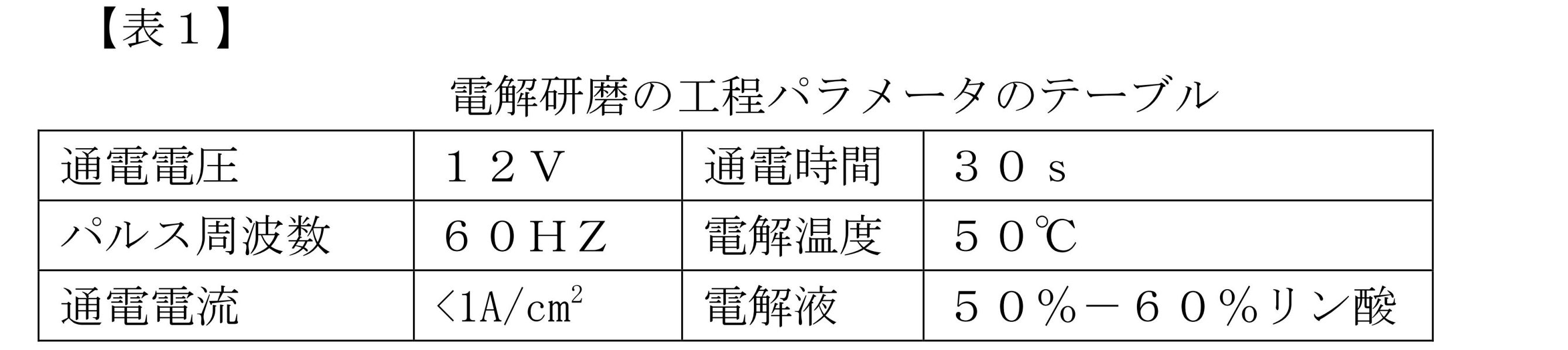
電解研磨の工程では、使用された液体吐出ピペットチップ110は、その内径が60μmであり、その外径が150μmである。電解研磨が完了した後に、金相顕微鏡により50倍拡大して観測した結果、明らかなこすり傷がない。 In the electropolishing process, the liquid-dispensing pipette tip 110 used has an inner diameter of 60 μm and an outer diameter of 150 μm. After the electropolishing is completed, there are no obvious scratches as a result of observing with a metallographic microscope at 50 times magnification.

前記ステップS260によれば、液体吐出ピペットチップ110の表面に非晶質シリコン膜を形成可能であり、化学気相成長(ChemicalVaporDeposition:CVD)法により、液体吐出ピペットチップ110の表面に非晶質シリコン膜を形成することが好ましい。非晶質シリコン膜の厚さが100Å乃至1000Åであることが好ましい。 According to step S260, an amorphous silicon film can be formed on the surface of the liquid ejection pipette tip 110, and the amorphous silicon film can be formed on the surface of the liquid ejection pipette tip 110 by a chemical vapor deposition (CVD) method. It is preferred to form a membrane. Preferably, the amorphous silicon film has a thickness of 100 Å to 1000 Å.

図25に示されるように、本出願に係る一実施例では、前記ステップS260は、脱イオン水により、前記液体吐出ピペットチップ110を洗浄又は浸漬するステップS261と、シラン化試薬により、前記液体吐出ピペットチップ110を処理するステップS262と、脱イオン水により、前記液体吐出ピペットチップ110を洗浄又は浸漬するステップS263とを含む。 As shown in FIG. 25, in one embodiment according to the present application, the step S260 includes a step S261 of washing or soaking the liquid ejection pipette tip 110 with deionized water, and a step S261 of washing or soaking the liquid ejection pipette tip 110 with a silanization reagent. It includes a step S262 of treating the pipette tip 110 and a step S263 of washing or immersing the liquid ejection pipette tip 110 in deionized water.

シラン化する前に、電解された液体吐出ピペットチップ110を脱イオン水により洗浄又は浸漬し、液体吐出ピペットチップ110の表面の汚れ及び静電を除去する。シラン化の処理により、液体吐出ピペットチップ110の表面自由エネルギーを低下させ、液体吐出ピペットチップ110の表面自由エネルギーを一定の区間に制限し、微小液滴199の生成工程に対する液体吐出ピペットチップ110の表面特性の影響を低減することができる。シラン化された後に、シラン化された液体吐出ピペットチップ110を脱イオン水により洗浄又は浸漬し、液体吐出ピペットチップ110の表面の汚れ及び静電を除去する。前記ステップS262に、シラン化の試薬により、化学気相成長法を利用して液体吐出ピペットチップ110の表面に非晶質シリコン膜を形成することが好ましい。好ましくは、シラン化の試薬は、四水素化ケイ素気体が含まれており、より好ましくは、四水素化ケイ素とドーパントである水素化リンとの混合気体が含まれる。液体吐出ピペットチップ110の表面に一つの非晶質シリコン膜を形成することにより、液体吐出ピペットチップ110の表面自由エネルギーを低減することができる。 Prior to silanization, the electrolyzed liquid-dispensing pipette tip 110 is washed or soaked in deionized water to remove contamination and static electricity on the surface of the liquid-dispensing pipette tip 110 . The silanization process lowers the surface free energy of the liquid-discharging pipette tip 110, limits the surface free energy of the liquid-discharging pipette tip 110 to a certain interval, and improves the surface free energy of the liquid-discharging pipette tip 110 for the minute droplet 199 generation process. The influence of surface properties can be reduced. After being silanized, the silanized liquid dispensing pipette tip 110 is washed or soaked in deionized water to remove contamination and static electricity on the surface of the liquid dispensing pipette tip 110 . Preferably, in step S262, an amorphous silicon film is formed on the surface of the liquid discharge pipette tip 110 using a chemical vapor deposition method using a silanizing reagent. Preferably, the silanizing reagent comprises silicon tetrahydride gas, more preferably a mixture of silicon tetrahydride and the dopant phosphorus hydride. By forming one amorphous silicon film on the surface of the liquid-discharging pipette tip 110, the surface free energy of the liquid-discharging pipette tip 110 can be reduced.

本実施例では、ステンレス鋼にその表面をシラン化する処理の具体的なステップは、電解されたステンレス鋼の材質の液体吐出ピペットチップ110を化学気相成長室に置いて、液体吐出ピペットチップ110の表面に水蒸気を除去させ、化学気相成長室を真空まで排気し、四水素化ケイ素と水素化リンとの混合気体を導入し、気相堆積の気圧を0.1Pa-500Paにし、しかも、気相堆積の温度を180℃-500℃にするように制御し、化学気相成長をさせ、0.4-8時間堆積し、堆積が完了すると、窒素ガスを導入して温度を室温まで下げるということである。具体的に、混合気体に前記四水素化ケイ素の体積パーセントが95.0%-99.9%であり、混合気体に前記水素化リンの体積パーセントが0.1%-5.0%である。 In this embodiment, the specific steps of the process of silanizing the surface of stainless steel are to place the liquid-dispensing pipette tip 110 made of electrolyzed stainless steel in a chemical vapor deposition chamber, and remove water vapor from the surface of the chemical vapor deposition chamber, evacuate the chemical vapor deposition chamber to vacuum, introduce a mixed gas of silicon tetrahydride and phosphorus hydride, and set the vapor deposition pressure to 0.1 Pa-500 Pa, and Control the vapor deposition temperature to 180° C.-500° C., perform chemical vapor deposition, deposit for 0.4-8 hours, and when the deposition is complete, introduce nitrogen gas and lower the temperature to room temperature. That's what it means. Specifically, the volume percentage of the silicon tetrahydride in the gas mixture is 95.0%-99.9%, and the volume percentage of the phosphorus hydride in the gas mixture is 0.1%-5.0%. .

図25に示されるように、前記ステップS270は、体積分率が0.5%-1.5%のジエチルピロカーボネート水溶液により、前記液体吐出ピペットチップ110を10分-20分浸漬するステップS271と、前記液体吐出ピペットチップ110を高圧で殺菌するステップS272を含む。体積分率が1%のDEPC水溶液により、液体吐出ピペットチップ110を浸漬し、液体吐出ピペットチップ110の表面にリボヌクレアーゼ(Ribonuclease、RNase)及びデオキシリボヌクレアーゼ(deoxyribonuclease、DNase)などがないように確保することにより、液体吐出ピペットチップ110を使用する引き続きの操作の干渉が低下する。前記液体吐出ピペットチップ110を高圧で殺菌することにより、液体吐出ピペットチップ110の表面に残られたDPEC水溶液を効果的に除去すると共に、DPEC水溶液に除去し切れなかったRNase及びDNaseなどを効果的に除去することができる。 As shown in FIG. 25, the step S270 includes a step S271 of immersing the liquid-dispensing pipette tip 110 in an aqueous diethylpyrocarbonate solution having a volume fraction of 0.5%-1.5% for 10-20 minutes. , a step S272 of sterilizing the liquid dispensing pipette tip 110 with high pressure. The liquid-dispensing pipette tip 110 is immersed in a DEPC aqueous solution with a volume fraction of 1% to ensure that the surface of the liquid-dispensing pipette tip 110 is free of ribonuclease (RNase) and deoxyribonuclease (DNase). This reduces interference with subsequent manipulations using the liquid dispensing pipette tip 110 . By high-pressure sterilization of the liquid-dispensing pipette tip 110, the DPEC aqueous solution remaining on the surface of the liquid-dispensing pipette tip 110 is effectively removed, and RNase and DNase, etc., which were not completely removed by the DPEC aqueous solution, are effectively removed. can be removed.

体積分率が1%のDEPC水溶液により、前記液体吐出ピペットチップ110を浸漬する時間は、具体的な状況に応じて設定されてもよい。さらに、前記ステップS271に、体積分率が1%のDEPC水溶液により前記液体吐出ピペットチップ110を浸漬する時間は15分である。測定結果からわかるように、15分とすれば、液体吐出ピペットチップ110の表面にRNase及びDNaseをきれいに除去するために十分である。さらに、前記ステップS280に、窒素ガス浄化炉により、液体吐出ピペットチップ110をさらに浄化し、液体吐出ピペットチップ110を浄化、乾燥及び焼成する。前記液体吐出ピペットチップ110を乾燥させるときに窒素ガスを保護気体として使用する。窒素ガスを保護気体として使用することは、雰囲気における化学の性質が比較的活性である気体と液体吐出ピペットチップ110の表面との化学反応を効果的に避けることができ、液体吐出ピペットチップ110に対する効果的な保護を実現することができる。 The time for immersing the liquid-dispensing pipette tip 110 in the DEPC aqueous solution with a volume fraction of 1% may be set according to a specific situation. Further, in step S271, the time for immersing the liquid discharge pipette tip 110 in the DEPC aqueous solution with a volume fraction of 1% is 15 minutes. As can be seen from the measurement results, 15 minutes is sufficient to cleanly remove RNase and DNase from the liquid dispensing pipette tip 110 surface. Further, in step S280, the liquid-dispensing pipette tip 110 is further purified in a nitrogen gas purifying furnace, and the liquid-dispensing pipette tip 110 is purified, dried, and baked. Nitrogen gas is used as a protective gas when drying the liquid dispensing pipette tip 110 . The use of nitrogen gas as the protective gas can effectively avoid chemical reaction between the gas whose chemical properties are relatively active in the atmosphere and the surface of the liquid-dispensing pipette tip 110, and the liquid-dispensing pipette tip 110 can be Effective protection can be achieved.

本出願に係る一つの具体的な実施例では、電解研磨の工程において、使用された液体吐出ピペットチップ110は、その内径が60μmであり、その外径が150μmである。電解された液体吐出ピペットチップ110を脱イオン水に5分浸漬する。そして、液体吐出ピペットチップ110を化学気相成長室に置いて、真空にすると、四水素化ケイ素と水素化リンとの混合気体を導入する。気相堆積の気圧を300±20Paにし、しかも、気相堆積の温度を350±20℃にするように制御する。混合気体には、前記四水素化ケイ素の体積パーセントが97.0%であり、前記水素化リンの体積パーセントが3.0%である。2時間堆積し、堆積が完了すると、窒素ガスを導入し、温度を室温まで下げる。脱イオン水により、シラン化された液体吐出ピペットチップ110を洗浄する。1%のDEPC水溶液により、液体吐出ピペットチップ110の全体を15分浸漬し、しかも、液体吐出ピペットチップ110を高圧で殺菌する。最後に、液体吐出ピペットチップ110を窒素浄化炉に置いてその表面を洗浄する。 In one specific embodiment of the present application, the liquid-dispensing pipette tip 110 used in the electropolishing process has an inner diameter of 60 μm and an outer diameter of 150 μm. The electrolyzed liquid-dispensing pipette tip 110 is immersed in deionized water for 5 minutes. Then, the liquid-dispensing pipette tip 110 is placed in the chemical vapor deposition chamber, and when the chamber is evacuated, a mixed gas of silicon tetrahydride and phosphorus hydride is introduced. The gas phase deposition pressure is controlled to 300±20 Pa and the vapor phase deposition temperature is controlled to 350±20°C. The gas mixture contains 97.0% by volume of said silicon tetrahydride and 3.0% by volume of said phosphorus hydride. Deposit for 2 hours, and when the deposition is complete, nitrogen gas is introduced and the temperature is lowered to room temperature. Wash the silanized liquid dispensing pipette tip 110 with deionized water. The entire liquid-discharging pipette tip 110 is immersed in a 1% DEPC aqueous solution for 15 minutes, and the liquid-discharging pipette tip 110 is sterilized under high pressure. Finally, the liquid-dispensing pipette tip 110 is placed in a nitrogen purge oven to clean its surface.

本出願に係る実施例が提供する液体吐出ピペットチップ110の表面処理方法により、18本の同じ寸法の液体吐出ピペットチップ110を一括して処理し、18本の液体吐出ピペットチップ110についてそれぞれ液滴195の吊り下げ試験を行う。流体制御機構により、第一の液体を液体吐出ピペットチップ110の出口端112から1.0nL/sの流速で排出する。先の一つの微小液滴199が落下するタイミングから計時して、各液体吐出ピペットチップ110について、100個の微小液滴199の落下時間を計算する。18本の液体吐出ピペットチップ110について、それぞれの対応する100個の液滴195の落下時間は、平均して以下のテーブルに示されている。

Figure 0007220366000011
18 liquid-discharging pipette tips 110 of the same size are processed collectively by the surface treatment method of the liquid-discharging pipette tip 110 provided by the embodiment of the present application, and droplets are applied to each of the 18 liquid-discharging pipette tips 110. 195 suspension test. A fluid control mechanism causes the first liquid to exit the outlet end 112 of the liquid dispensing pipette tip 110 at a flow rate of 1.0 nL/s. The falling time of 100 minute droplets 199 for each liquid discharge pipette tip 110 is calculated from the timing at which one minute droplet 199 falls. The drop times for each of the corresponding 100 droplets 195 for the 18 liquid dispensing pipette tips 110 are averaged and shown in the table below.
Figure 0007220366000011

18個の液体吐出ピペットチップ110について、それぞれの対応する微小液滴199の平均の落下時間の相対的な変化範囲は、18個の液体吐出ピペットチップ110間の表面自由エネルギーの相対的な変化範囲を直接に示すことができる。上記の試験データからわかるように、本出願の実施例が提供する液体吐出ピペットチップ110表面処理方法により、一括して処理された液体吐出ピペットチップ110の表面自由エネルギーの標準偏差は1.33%であり、微小液滴199を生成する各種類の体積について、その均一性への要求が十分に満たされている。 For the 18 liquid-dispensing pipette tips 110, the relative variation range of the average falling time of each corresponding microdroplet 199 is the relative variation range of the surface free energy among the 18 liquid-dispensing pipette tips 110. can be shown directly. As can be seen from the above test data, the standard deviation of the surface free energy of the liquid-discharging pipette tips 110 that are collectively treated by the liquid-discharging pipette tip 110 surface treatment method provided by the embodiment of the present application is 1.33%. and for each type of volume that produces microdroplets 199, the homogeneity requirements are well met.

本出願に係る一実施例では、液体吐出ピペットチップ110は、その一方端が出口端112であり、前記液体吐出ピペットチップの表面処理方法は、液体吐出ピペットチップ110の出口端112及び外側壁を表面処理するために用いられる。同時に、液体吐出ピペットチップ110の出口端112及び外側壁を表面処理し、微小液滴199を生成する工程には、液体吐出ピペットチップ110の出口端及び外側壁が生成された微小液滴199に接触した後に、その均一な表面が微小液滴199を押し出すことにより、微小液滴199の破壊を効果的に避けることができる。 In one embodiment of the present application, the liquid dispensing pipette tip 110 has an outlet end 112 at one end thereof, and the method of surface treatment of the liquid dispensing pipette tip includes the outlet end 112 and the outer wall of the liquid dispensing pipette tip 110. Used for surface treatment. At the same time, the step of surface treating the outlet end 112 and the outer wall of the liquid-dispensing pipette tip 110 to generate microdroplets 199 includes: After contact, the uniform surface pushes the microdroplets 199 out, effectively avoiding breakage of the microdroplets 199 .

従来の流体駆動機構により微小液滴を生成する工程では、液体吐出ピペットチップの出口端が運動中の状態にあることから、排出された液体の流速が不安定で、かつ、制御不可能になる。そして、生成された微小液滴は、その体積にランダム性が現れている。このことに鑑み、従来の液体吐出ピペットチップが運動していると、排出された液体の流速が不安定でかつ制御不可能となることにより微小液滴の体積にランダム性が現れているという課題について、液体吐出ピペットチップが所定流速で液体を排出することを確保可能な流体駆動機構を提供するニーズが存在している。 In the process of generating microdroplets by a conventional fluid drive mechanism, the outlet end of the liquid ejection pipette tip is in motion, so the flow velocity of the ejected liquid becomes unstable and uncontrollable. . Randomness appears in the volume of the generated microdroplets. In view of this, when a conventional liquid ejection pipette tip is in motion, the flow velocity of the ejected liquid becomes unstable and uncontrollable, resulting in randomness in the volume of microdroplets. There is a need to provide a fluid drive mechanism that can ensure that a liquid dispensing pipette tip dispenses liquid at a predetermined flow rate.

微小液滴199を生成する工程では、第一の液体が所定流速で液体吐出ピペットチップ110の出口端112から排出される。液体吐出ピペットチップ110の出口端112は、瞬間加速度運動を含む周期的な運動を行うと、微小液滴199を効果的に生成することができるだけでなく、生成される微小液滴199の寸法を制御することに役立つ。液体吐出ピペットチップ110の出口端112は、正弦波状に変位して周期的な運動を行う時に、微小液滴199を効果的に生成することができるだけでなく、生成された微小液滴199の体積がよい均一性を持っている。上記の微小液滴199を生成する二つの工程では、第一の液体が流体駆動機構120の駆動により、所定流速で液体吐出ピペットチップ110の出口端112から排出される。 In the step of generating microdroplets 199, the first liquid is ejected from the outlet end 112 of the liquid ejection pipette tip 110 at a predetermined flow rate. The outlet end 112 of the liquid dispensing pipette tip 110 can not only effectively generate microdroplets 199 when subjected to periodic motion, including momentary acceleration motion, but also control the size of the microdroplets 199 generated. Helps control. The outlet end 112 of the liquid ejection pipette tip 110 can not only effectively generate microdroplets 199 when it is sinusoidally displaced and undergoes periodic motion, but also the volume of the generated microdroplets 199 is have good uniformity. In the two steps of generating microdroplets 199 described above, the first liquid is driven by the fluid drive mechanism 120 to be ejected from the outlet end 112 of the liquid ejection pipette tip 110 at a predetermined flow rate.

図26及び図27に示されるように、本出願が提供流体駆動機構120は、微小液滴生成システムに用いられており、容積可変アセンブリ121及びパワーアセンブリ122を含む。容積可変アセンブリ121は、シリンジ1211及びブッシュロッド1212を含む。ブッシュロッド1212は、シリンジ1211の内壁と摺動するように協働し、シリンジ1211に駆動液体1214を貯留可能である。シリンジ1211は、第一の液体190を貯留する液体吐出ピペットチップ110の入口端111に連通するための液体出入口1213を有する。パワーアセンブリ122は、ブッシュロッド1212に動力伝達可能に接続され、ブッシュロッド1212がシリンジ1211の延在方向に沿って摺動するように駆動するために用いられる。微小液滴199を生成する工程には、パワーアセンブリ122は、ブッシュロッド1212がシリンジ1211に貯留されている駆動液体1214を押圧するように駆動し、駆動液体1214が液体吐出ピペットチップ110に貯留されている第一の液体190を押圧し、そして、第一の液体190を液体吐出ピペットチップ110の出口端112から排出する。 As shown in FIGS. 26 and 27, the fluid drive mechanism 120 provided by the present application is used in a microdroplet generating system and includes a variable volume assembly 121 and a power assembly 122. FIG. Variable volume assembly 121 includes syringe 1211 and bushing rod 1212 . The bushing rod 1212 is slidably cooperating with the inner wall of the syringe 1211 to allow the driving liquid 1214 to be stored in the syringe 1211 . Syringe 1211 has liquid inlet/outlet 1213 for communicating with inlet end 111 of liquid-dispensing pipette tip 110 storing first liquid 190 . The power assembly 122 is power-transmittably connected to the bush rod 1212 and used to drive the bush rod 1212 to slide along the extending direction of the syringe 1211 . In the step of generating microdroplets 199 , power assembly 122 drives bushing rod 1212 to push driving liquid 1214 stored in syringe 1211 , and driving liquid 1214 is stored in liquid dispensing pipette tip 110 . The first liquid 190 is pushed out and the first liquid 190 is expelled from the outlet end 112 of the liquid dispensing pipette tip 110 .

本出願が提供する流体駆動機構120は、液体(駆動液体1214)の非圧縮性により、液体吐出ピペットチップ110の出口端112が、高周波数で振動している時でも、所定流速で第一の液体190を液体吐出ピペットチップ110の出口端112から排出するということを確保することができる。本出願が提供する流体駆動機構120は、生成された微小液滴199の体積を正確に制御することができる。本出願が提供する流体駆動機構120は、上記実施方式に限定されず、例えば、蠕動ポンプ、加圧駆動ポンプ、空気圧駆動ポンプ、電気浸漬駆動ポンプ等が適用されてもよい。 The fluid drive mechanism 120 provided by the present application allows the outlet end 112 of the liquid dispensing pipette tip 110 to move at a predetermined flow rate due to the incompressibility of the liquid (drive liquid 1214), even when vibrating at high frequencies. It can be ensured that the liquid 190 is expelled from the outlet end 112 of the liquid dispensing pipette tip 110 . The fluid drive mechanism 120 provided by the present application can precisely control the volume of the generated microdroplets 199 . The fluid drive mechanism 120 provided by the present application is not limited to the above-described embodiment, and may be applied to, for example, a peristaltic pump, a pressure drive pump, a pneumatic drive pump, an electric immersion drive pump, or the like.

一つの実施可能な形態として、シリンジ1211の液体出入口1213は、液体吐出ピペットチップ110の入口端111に細管123を介して連通される。シリンジ1211と細管123には、駆動液体1214が貯留されている。パワーアセンブリ122は、容積可変アセンブリ121のブッシュロッド1212に動力伝達可能に接続され、パワーアセンブリ122は、容積可変アセンブリ121のブッシュロッド1212がシリンジ1211を摺動するように押し出すために用いられる。微小液滴199の生成工程では、パワーアセンブリ122が容積可変アセンブリ121のブッシュロッド1212を押し出し、ブッシュロッド1212がシリンジ1211及び細管123に貯留されている駆動液体1214を押圧し、駆動液体1214が液体吐出ピペットチップ110に貯留されている第一の液体190を押圧し、そして、第一の液体190を液体吐出ピペットチップ110の出口端112から排出する。細管123により、シリンジ1211の液体出入口1213を液体吐出ピペットチップ110の入口端111に接続していると、まず、細管123の内径が比較的小さいため、ブッシュロッド1212の行程を制御することにより、排出液体の体積を正確に制御することができ、次に、細管123により、シリンジ1211と液体吐出ピペットチップ110との位置及び距離を自由に設置し、シリンジ1211と液体吐出ピペットチップ110との間に他の必要な設備を設置することを便宜にすることができる。 As one possible embodiment, the liquid inlet/outlet 1213 of the syringe 1211 communicates with the inlet end 111 of the liquid-dispensing pipette tip 110 via the capillary tube 123 . A driving liquid 1214 is stored in the syringe 1211 and the narrow tube 123 . The power assembly 122 is power-transmittably connected to the bush rod 1212 of the variable volume assembly 121 , and the power assembly 122 is used for the bush rod 1212 of the variable volume assembly 121 to slidably push the syringe 1211 . In the step of generating the micro droplets 199, the power assembly 122 pushes out the bush rod 1212 of the variable volume assembly 121, the bush rod 1212 presses the driving liquid 1214 stored in the syringe 1211 and the capillary tube 123, and the driving liquid 1214 is liquid. The first liquid 190 stored in the dispensing pipette tip 110 is pressed and the first liquid 190 is expelled from the outlet end 112 of the liquid dispensing pipette tip 110 . When the capillary tube 123 connects the liquid inlet/outlet port 1213 of the syringe 1211 to the inlet end 111 of the liquid-dispensing pipette tip 110, first, since the inner diameter of the capillary tube 123 is relatively small, by controlling the stroke of the bush rod 1212, The volume of discharged liquid can be precisely controlled, and then the position and distance between the syringe 1211 and the liquid-dispensing pipette tip 110 can be freely set by the thin tube 123, and the distance between the syringe 1211 and the liquid-dispensing pipette tip 110 can be adjusted. It may be convenient to install other necessary equipment in the

本出願に係る一実施例では、パワーアセンブリ122は、押し出しブッシュロッド1212がシリンジ1211を均一な速度で摺動するように押し出し、言い換えると、液体1214をブッシュロッド1212の押し出しにより均一な流速で容積可変アセンブリ121の液体出入口1213から排出し、細管123を介して均一な流速で液体吐出ピペットチップ110に進入するように駆動する。液体吐出ピペットチップ110に貯留されている第一の液体190は、駆動液体1214の押し出しにより、均一な流速で液体吐出ピペットチップ110の出口端112から排出される。駆動液体1214を伝動媒体として利用し、ブッシュロッド1212が均一な流速で駆動液体1214を排出するように制御することにより、本実施例が提供する流体駆動機構120は、液体吐出ピペットチップ110が静止状態にあるときに均一な流速で第一の液体190を液体吐出ピペットチップ110の出口端112から排出できるだけでなく、液体吐出ピペットチップ110が急速に振動する最中の状態にあっても、本実施例が提供する流体駆動機構120が依然として第一の液体190を液体吐出ピペットチップ110の出口端112から均一な流速で排出することも確保することができる。本実施例が提供する流体駆動機構120は、生成された微小液滴199の体積の均一性を大幅に高めることができる。 In one embodiment of the present application, the power assembly 122 extrudes the syringe 1211 such that the pusher bushing rod 1212 slides at a uniform velocity, in other words, the liquid 1214 is displaced through the volume at a uniform flow rate by the push of the bushing rod 1212 . It is driven to discharge from the liquid inlet/outlet port 1213 of the variable assembly 121 and enter the liquid-dispensing pipette tip 110 at a uniform flow rate through the capillary tube 123 . The first liquid 190 stored in the liquid-discharging pipette tip 110 is discharged from the outlet end 112 of the liquid-discharging pipette tip 110 at a uniform flow rate due to the extrusion of the driving liquid 1214 . By using the driving liquid 1214 as a power transmission medium and controlling the bush rod 1212 to discharge the driving liquid 1214 at a uniform flow rate, the fluid driving mechanism 120 provided by this embodiment provides the liquid ejection pipette tip 110 with a stationary motion. Not only can the first liquid 190 be expelled from the outlet end 112 of the liquid dispensing pipette tip 110 at a uniform flow rate when the liquid dispensing pipette tip 110 is in a state of rapid vibration, the present It can also ensure that the fluid drive mechanism 120 provided by the embodiment still ejects the first liquid 190 from the outlet end 112 of the liquid dispensing pipette tip 110 at a uniform flow rate. The fluid drive mechanism 120 provided by this embodiment can greatly enhance the volume uniformity of the generated microdroplets 199 .

パワーアセンブリ122は、ブッシュロッド1212がシリンジ1211に液体出入口1213から離れる方向又は液体出入口1213に近接する方向に沿って摺動するように連動するということに役割を持っている。好ましくは、パワーアセンブリ122が、直動運動を直接に出力するシリンダや油圧缸などのアセンブリであり、例えば、モーターと同期プーリの組み合わせやモーターとネジ棒1222及びスライドブロック1223の組み合わせなどの円運動を直動運動に変換するアセンブリであってもよい。本出願では、パワーアセンブリ122の具体的な構造が限定されていない。図27に示されるように、本出願に係る一実施例では、パワーアセンブリ122が駆動モーター1221、ネジ棒1222及びスライドブロック1223を含む。駆動モーター1221は、その出力軸がネジ棒1222の一方端に動力伝達可能に接続され、スライドブロック1223が雌ねじを有し、スライドブロック1223がネジ棒1222の表面の雄ねじに協働して接続される。スライドブロック1223の外縁は、ブッシュロッド1212におけるシリンジ1211から離れる一方端に固定接続される。スライドブロック1223は、ネジ棒1222と協働して、駆動モーター1221が出力する回転運動を、ネジ棒1222の軸方向に沿うスライドブロック1223の直動運動に変換し、容積可変アセンブリ121のブッシュロッド1212がシリンジ1211を摺動するように連動する。さらに、本実施例が使用する駆動モーター1221は、サーボモーターである。サーボモーターは、出力角度の変位を正確にフィードバック制御できるという特徴を持っている。 The power assembly 122 is responsible for engaging the bushing rod 1212 with the syringe 1211 to slide along a direction away from or closer to the liquid port 1213 . Preferably, the power assembly 122 is an assembly such as a cylinder or hydraulic line that directly outputs linear motion, such as a motor and synchronous pulley combination or a motor and threaded rod 1222 and slide block 1223 combination. to translational motion. The application does not limit the specific structure of the power assembly 122 . 27, in one embodiment of the present application, power assembly 122 includes drive motor 1221, threaded rod 1222 and slide block 1223. As shown in FIG. The drive motor 1221 has its output shaft connected to one end of the threaded rod 1222 so as to be able to transmit power, the slide block 1223 having a female thread, and the slide block 1223 being cooperatively connected to the male thread on the surface of the threaded rod 1222 . be. The outer edge of slide block 1223 is fixedly connected to one end of bush rod 1212 away from syringe 1211 . The slide block 1223 cooperates with the threaded rod 1222 to convert the rotational motion output by the drive motor 1221 into the linear motion of the slide block 1223 along the axial direction of the threaded rod 1222, and the bush rod of the variable volume assembly 121. 1212 engages to slide syringe 1211 . Furthermore, the drive motor 1221 used in this embodiment is a servo motor. Servomotors have the advantage of being able to accurately feedback control the displacement of the output angle.

図28に示されるように、本出願に係る一実施例では、流体駆動機構120は、さらに、三方切替弁124と貯液タンク125を含む。三方切替弁124は、第一のポート、第二のポート及び第三のポートを有する。液体吐出ピペットチップ110の入口端111、容積可変アセンブリ121の液体出入口1213及び貯液タンク125は、三方切替弁124の第一のポート、第二のポート及び第三のポートに、それぞれ連通される。三方切替弁124は、少なくとも、流体駆動機構120を制御して以下の二つのモードを実施可能である。一番目のモードでは、容積可変アセンブリ121の液体出入口1213を液体吐出ピペットチップ110の入口端111に連通し、パワーアセンブリ122の連動により、容積可変アセンブリ121が液体吐出ピペットチップ110の液体に駆動力をかけ、液体吐出ピペットチップ110内の第一の液体190を液体吐出ピペットチップ110の出口端112から排出し、又は、第一の液体190を液体吐出ピペットチップ110の出口端112から液体吐出ピペットチップ110に吸入するようにする。二番目のモードでは、容積可変アセンブリ121の液体出入口1213を貯液タンク125に連通し、パワーアセンブリ122の連動により、容積可変アセンブリ121が貯液タンク125中の駆動液体1214を容積可変アセンブリ121のシリンジ1211に吸入し、又は、容積可変アセンブリ121内の駆動液を貯液タンク125に押し出すようにする。 As shown in FIG. 28, in one embodiment according to the present application, the fluid drive mechanism 120 further includes a three-way switching valve 124 and a reservoir tank 125 . The three-way switching valve 124 has a first port, a second port and a third port. The inlet end 111 of the liquid-dispensing pipette tip 110, the liquid inlet/outlet 1213 of the variable volume assembly 121, and the liquid storage tank 125 are communicated with the first, second, and third ports of the three-way switching valve 124, respectively. . The three-way switching valve 124 can control at least the fluid drive mechanism 120 to implement the following two modes. In the first mode, the liquid port 1213 of the variable volume assembly 121 is connected to the inlet end 111 of the liquid dispensing pipette tip 110, and the power assembly 122 interlocks so that the variable volume assembly 121 exerts a driving force on the liquid in the liquid dispensing pipette tip 110. to expel the first liquid 190 in the liquid-dispensing pipette tip 110 from the outlet end 112 of the liquid-dispensing pipette tip 110; Try to inhale into the tip 110 . In the second mode, the liquid inlet/outlet port 1213 of the volume variable assembly 121 is communicated with the liquid storage tank 125, and the power assembly 122 is interlocked to cause the volume variable assembly 121 to move the drive liquid 1214 in the liquid storage tank 125 to the volume variable assembly 121. The driving liquid in the volume variable assembly 121 is sucked into the syringe 1211 or pushed out to the liquid storage tank 125 .

図28に示されるように、本出願に係る一実施例は、上記流体駆動機構を利用し、以下の四つのステップを含む流体駆動方法をさらに提供する。ステップ(1)では、三方切替弁124を介して、容積可変アセンブリ121の液体出入口1213を貯液タンク125に連通し、パワーアセンブリ122の連動により、ブッシュロッド1212に液体出入口1213から離れるシリンジ1211の一方端内を摺動させ、シリンジ1211の容積を変更し、貯液タンク125内の駆動液体1214をシリンジ1211に吸入する。ステップ(2)では、三方切替弁124を介して、容積可変アセンブリ121の液体出入口1213を液体吐出ピペットチップ110の入口端111に連通し、パワーアセンブリ122の連動により、ブッシュロッド1212に液体出入口1213に近接するシリンジ1211の一方端内を摺動させ、シリンジ1211の容積を変更し、シリンジ1211内、細管123内及び液体吐出ピペットチップ110内の気体を排出する。ステップ(3)では、液体吐出ピペットチップ110の出口端112を第一の液体190に進入し、三方切替弁124を介して容積可変アセンブリ121の液体出入口1213を液体吐出ピペットチップ110の入口端111に連通することを維持し、パワーアセンブリ122の連動により、ブッシュロッド1212に液体出入口1213から離れるシリンジ1211の一方端内を摺動させ、シリンジ1211の容積を変更し、第一の液体190を液体吐出ピペットチップ110に吸入する。ステップ(4)では、三方切替弁124を介して、容積可変アセンブリ121の液体出入口1213を液体吐出ピペットチップ110の入口端111に連通することを維持し、パワーアセンブリ122の連動により、ブッシュロッド1212に液体出入口1213から離れるシリンジ1211の一方端内を均一な速度で摺動させ、シリンジ1211の容積を変更し、液体吐出ピペットチップ110に貯留されている第一の液体190を均一な流速で液体吐出ピペットチップ110の出口端112から排出する。 As shown in FIG. 28, an embodiment of the present application further provides a fluid drive method using the fluid drive mechanism described above and including the following four steps. In step (1), the liquid inlet/outlet 1213 of the variable volume assembly 121 is communicated with the liquid storage tank 125 via the three-way switching valve 124, and the power assembly 122 is interlocked with the bush rod 1212 to move the syringe 1211 away from the liquid inlet/outlet 1213. One end is slid to change the volume of syringe 1211 , and driving liquid 1214 in liquid storage tank 125 is sucked into syringe 1211 . In step (2), the liquid inlet/outlet 1213 of the volume variable assembly 121 is communicated with the inlet end 111 of the liquid-dispensing pipette tip 110 via the three-way switching valve 124, and the power assembly 122 is interlocked with the bush rod 1212 to open the liquid inlet/outlet 1213. , the volume of the syringe 1211 is changed, and the gas inside the syringe 1211, the narrow tube 123, and the liquid ejection pipette tip 110 is discharged. In step (3), the outlet end 112 of the liquid-dispensing pipette tip 110 enters the first liquid 190 , and the liquid inlet/outlet port 1213 of the variable volume assembly 121 is moved through the three-way switching valve 124 to the inlet end 111 of the liquid-dispensing pipette tip 110 . and the engagement of power assembly 122 causes bushing rod 1212 to slide within one end of syringe 1211 away from liquid port 1213 to change the volume of syringe 1211 and change first liquid 190 to liquid. Aspirate into the dispensing pipette tip 110 . In step (4), the liquid inlet/outlet 1213 of the variable volume assembly 121 is maintained in communication with the inlet end 111 of the liquid dispensing pipette tip 110 via the three-way switching valve 124, and the engagement of the power assembly 122 causes the bush rod 1212 to One end of the syringe 1211 away from the liquid inlet/outlet 1213 is slid at a uniform speed to change the volume of the syringe 1211, and the first liquid 190 stored in the liquid discharge pipette tip 110 is dispensed at a uniform flow rate. Discharge from outlet end 112 of dispensing pipette tip 110 .

上記第二のステップにシリンジ1211内の気体を順調に排出させるように、図27に示されるように、装着される時に、シリンジ1211の液体出入口1213が上向きにし、ブッシュロッド1212が垂直方向にシリンジ1211内を摺動するようにする。 In order to expel the gas in the syringe 1211 smoothly in the second step, the liquid inlet/outlet port 1213 of the syringe 1211 faces upward and the bushing rod 1212 extends vertically when installed, as shown in FIG. 1211 is made to slide.

微小液滴199を生成する効率を高めるために、一つの実施可能な形態として、液体吐出ピペットチップ110の数が複数であり、複数の液体吐出ピペットチップ110が並列に間隔配置され、又は、他の形式で配置されてもよい。各液体吐出ピペットチップ110は、いずれも、個別の細管123を介して、三方切替弁124の第一のポートに連通される。容積可変アセンブリ121の数は、一つであり、容積可変アセンブリ121の液体出入口1213が、三方切替弁124の第二のポートに連通される。三方切替弁124の第三のポートが、貯液タンク125に連通される。パワーアセンブリ122の駆動により、ブッシュロッド1212がシリンジ1211を液体出入口1213に近接する方向に沿って均一な速度で摺動すると共に、駆動液体1214を複数の液体吐出ピペットチップ110に押圧する。複数の細管123が並列接続されているため、各細管123内の駆動液体1214の流量が同じであり、複数の液体吐出ピペットチップ110内の第一の液体190を、同等かつ一定の流速で液体吐出ピペットチップ110の出口端112を排出することを確認することができ、さらに、生成された微小液滴199の体積の均一性を確認することができる。 To increase the efficiency of generating microdroplets 199, in one possible embodiment, the number of liquid dispensing pipette tips 110 is multiple, multiple liquid dispensing pipette tips 110 are spaced in parallel, or otherwise arranged. may be arranged in the form of Each liquid discharge pipette tip 110 is communicated with a first port of a three-way switching valve 124 via an individual thin tube 123 . The number of variable volume assemblies 121 is one, and the liquid inlet/outlet port 1213 of the variable volume assembly 121 communicates with the second port of the three-way switching valve 124 . A third port of the three-way switching valve 124 communicates with the liquid storage tank 125 . Driving the power assembly 122 causes the bushing rod 1212 to slide the syringe 1211 at a uniform speed along the direction toward the liquid port 1213 and press the driving liquid 1214 against the plurality of liquid dispensing pipette tips 110 . Since the plurality of capillaries 123 are connected in parallel, the flow rate of the driving liquid 1214 in each capillaries 123 is the same, and the first liquid 190 in the plurality of liquid-discharging pipette tips 110 is dispensed at an equal and constant flow rate. Ejecting the outlet end 112 of the dispensing pipette tip 110 can be verified, and the volume uniformity of the generated microdroplets 199 can be verified.

微小液滴199を生成する効率を高めるために、他の一つの実施可能な形態として、液体吐出ピペットチップ110及び容積可変アセンブリ121の数は、いずれも複数である。複数の液体吐出ピペットチップ110が並列に間隔配置され、又は、他の形式で配置されてもよい。各液体吐出ピペットチップ110は、いずれも、個別の細管123を介して三方切替弁124の第一のポートに連通される。各容積可変アセンブリ121の液体出入口1213も、細管123を介して、三方切替弁124の第二のポートに連通される。三方切替弁124の第三のポートが貯液タンク125に連通される。複数の容積可変アセンブリ121が並列に間隔配置され、又は、他の形式で配置されてもよい。複数の容積可変アセンブリ121は、シリンジ1211から離れるブッシュロッド1212の一方端が対向して固定され、パワーアセンブリ122により同期に押し出される。パワーアセンブリ122の駆動により、複数のブッシュロッド1212がそれぞれのシリンジ1211を液体出入口1213に近接する方向に沿って均一な速度で摺動すると共に、駆動液体1214を複数の液体吐出ピペットチップ110まで押し出す。複数の細管123が並列接続されているため、各細管123内の駆動液体1214の流量が同じであり、複数の液体吐出ピペットチップ110内の第一の液体190を同等、かつ、一定の流速で液体吐出ピペットチップ110の出口端112から排出することを確保することができ、さらに、生成された微小液滴199の体積の均一性を確保することができる。 In order to increase the efficiency of generating microdroplets 199, in another possible mode, the number of liquid ejection pipette tips 110 and variable volume assemblies 121 are both plural. A plurality of liquid dispensing pipette tips 110 may be spaced side by side or otherwise arranged. Each liquid-discharging pipette tip 110 communicates with a first port of a three-way switching valve 124 via an individual thin tube 123 . The liquid inlet/outlet port 1213 of each volume variable assembly 121 is also communicated with the second port of the three-way switching valve 124 via the thin tube 123 . A third port of the three-way switching valve 124 communicates with the liquid storage tank 125 . A plurality of variable volume assemblies 121 may be spaced side-by-side or otherwise arranged. The plurality of variable volume assemblies 121 are fixed with one end of the bush rod 1212 away from the syringe 1211 facing each other, and are synchronously pushed out by the power assembly 122 . Driving the power assembly 122 causes the plurality of bushing rods 1212 to slide the respective syringes 1211 at a uniform speed along the direction close to the liquid inlet/outlet port 1213 and push the drive liquid 1214 to the plurality of liquid dispensing pipette tips 110. . Since the plurality of capillaries 123 are connected in parallel, the flow rate of the driving liquid 1214 in each capillaries 123 is the same, and the first liquid 190 in the plurality of liquid-discharging pipette tips 110 is dispensed at the same and constant flow rate. Ejection from the outlet end 112 of the liquid ejection pipette tip 110 can be ensured, and furthermore, volume uniformity of the generated microdroplets 199 can be ensured.

微小液滴199を生成する効率を高めるために、三番目の実施可能な形態として、図29に示されるように、液体吐出ピペットチップ110、容積可変アセンブリ121及び三方切替弁124は、それらの数が同じであり、かつ、いずれも複数である。各液体吐出ピペットチップ110の入口端111は、それぞれ、個別の細管123を介して、一つの三方切替弁124の第一のポートに連通される。各容積可変アセンブリ121の液体出入口1213は、個別の細管123を介して、一つの三方切替弁124の第二のポートに、それぞれ連通される。各三方切替弁124の第三のポートは、貯液タンク125に、それぞれ連通される。好ましくは、貯液タンク125が一つ又は複数である。各液体吐出ピペットチップ110内の第一の液体190は、同じでもよく異なってもよい。複数の容積可変アセンブリ121は、並列に間隔配置され、又は、他の形式で配置されてもよい。複数の容積可変アセンブリ121は、シリンジ1211から離れるブッシュロッド1212の一方端が対向して固定され、パワーアセンブリ122により同期に押し出される。パワーアセンブリ122の駆動により、複数のブッシュロッド1212は、それぞれのシリンジ1211を液体出入口1213に近接する方向に沿って均一な速度で摺動する。複数の異なる種類の微小液滴199を同時に生成することができる。 In order to increase the efficiency of generating microdroplets 199, as a third possible embodiment, as shown in FIG. are the same and both are plural. The inlet end 111 of each liquid-dispensing pipette tip 110 is communicated with the first port of one three-way switching valve 124 via a separate capillary tube 123 . The liquid inlet/outlet port 1213 of each volume variable assembly 121 is communicated with the second port of one three-way switching valve 124 through individual capillaries 123 . A third port of each three-way switching valve 124 communicates with a liquid storage tank 125 . Preferably, there is one or more reservoir tanks 125 . The first liquid 190 in each liquid dispensing pipette tip 110 may be the same or different. The plurality of variable volume assemblies 121 may be spaced side by side or otherwise arranged. A plurality of variable volume assemblies 121 are fixed so that one end of bush rod 1212 away from syringe 1211 faces and is pushed out synchronously by power assembly 122 . Driving the power assembly 122 causes the plurality of bushing rods 1212 to slide their respective syringes 1211 at a uniform speed along the direction toward the liquid port 1213 . Multiple different types of microdroplets 199 can be generated simultaneously.

微小液滴199を生成する効率を高めるために、四番目の実施可能な形態として、液体吐出ピペットチップ110、容積可変アセンブリ121及び三方切替弁124は、それらの数が同じであり、かつ、いずれも複数である。各液体吐出ピペットチップ110の入口端111は、個別の細管123を介して、一つの三方切替弁124の第一のポートに、それぞれ連通される。各容積可変アセンブリ121の液体出入口1213は、個別の細管123を介して一つの三方切替弁124の第二のポートに連通される。各三方切替弁124の第三のポートは、貯液タンク125に、それぞれ連通される。好ましくは、貯液タンク125は一つの又は複数である。各液体吐出ピペットチップ110内の第一の液体190は、同じでもよく異なってもよい。複数の容積可変アセンブリ121は、並列に間隔配置され、他の形式で配置されてもよい。各容積可変アセンブリ121は、個別のパワーアセンブリ122に、それぞれ対応している。パワーアセンブリ122の駆動により、複数のブッシュロッド1212がそれぞれのシリンジ1211を液体出入口1213に近接する方向に沿って均一な速度で摺動する。複数の異なる種類の微小液滴199を同時に生成することができるだけでなく、各液体吐出ピペットチップ110により生成された微小液滴199の体積の均一性を確保できることを前提として、さらに、各種類の液滴195の体積を個別に制御することができ、複数の液体吐出ピペットチップ110の微小液滴199の生成状態を個別に制御することに役立つ。 In order to increase the efficiency of generating microdroplets 199, as a fourth possible embodiment, the liquid ejection pipette tip 110, the variable volume assembly 121 and the three-way switching valve 124 are equal in number and is also plural. The inlet end 111 of each liquid-dispensing pipette tip 110 is communicated with the first port of one three-way switching valve 124 via individual capillaries 123 . The liquid inlet/outlet port 1213 of each volume variable assembly 121 is communicated with the second port of one three-way switching valve 124 via individual capillaries 123 . A third port of each three-way switching valve 124 communicates with a liquid storage tank 125 . Preferably, there is one or more reservoir tanks 125 . The first liquid 190 in each liquid dispensing pipette tip 110 may be the same or different. The plurality of variable volume assemblies 121 may be spaced side by side and arranged in other manners. Each variable volume assembly 121 corresponds to an individual power assembly 122, respectively. Driving the power assembly 122 causes the plurality of bushing rods 1212 to slide their respective syringes 1211 at a uniform speed along a direction proximate to the liquid port 1213 . On the premise that it is possible not only to simultaneously generate a plurality of different types of microdroplets 199, but also to ensure the uniformity of the volume of the microdroplets 199 generated by each liquid ejection pipette tip 110, each type of The volume of droplets 195 can be individually controlled, which is useful for individually controlling the generation state of micro droplets 199 of a plurality of liquid ejection pipette tips 110 .

従来の運動制御機構が使用される工程では、液体吐出ピペットチップの出口端と油相組成物との対向運動を正確に制御できず、生成された微小液滴の体積の均一性が比較的高くない。 In processes where conventional motion control mechanisms are used, the counter motion between the outlet end of the liquid ejection pipette tip and the oil phase composition cannot be controlled accurately, and the volume uniformity of the generated microdroplets is relatively high. do not have.

このことに鑑み、液体吐出ピペットチップの注射/噴射法により微小液滴を生成する際に、従来の運動制御機構により液体吐出ピペットチップの出口端と油相組成物との対向運動を正確に制御できず、生成された微小液滴の体積の均一性が比較的高くないという課題について、液体吐出ピペットチップの出口端と油相組成物との対向運動を正確に制御できる運動制御機構を提供するニーズが存在している。 In view of this, when microdroplets are generated by the injection/jetting method of the liquid-dispensing pipette tip, the counter motion between the outlet end of the liquid-dispensing pipette tip and the oil phase composition is accurately controlled by a conventional motion control mechanism. Disclosed is a motion control mechanism capable of accurately controlling the counter motion between the outlet end of a liquid-dispensing pipette tip and the oil-phase composition. a need exists.

微小液滴199の生成工程では、液体吐出ピペットチップ110の出口端112は、瞬間加速度運動を含む周期的な運動を行うことから、微小液滴199を効果的に生成することができるだけでなく、生成された微小液滴199の寸法を便宜に制御することに役立つ。液体吐出ピペットチップ110の出口端112は、正弦波状に変位して周期的な運動を行うことから、微小液滴199を効果的に生成することができるだけでなく、生成された微小液滴199は、その体積がよい均一性を持っている。液体吐出ピペットチップ110の出口端112は、運動制御機構130の駆動により、瞬間加速度運動を含む周期的に運動、又は、正弦波状に変位して周期的な運動を行う。 In the process of generating the microdroplets 199, the outlet end 112 of the liquid ejection pipette tip 110 undergoes periodic motion including momentary acceleration motion, which not only can effectively generate the microdroplets 199, It helps to conveniently control the size of the generated microdroplets 199 . Since the outlet end 112 of the liquid-discharging pipette tip 110 is displaced in a sinusoidal manner and performs periodic motion, it is possible not only to effectively generate microdroplets 199, but also to generate microdroplets 199. , whose volume has good uniformity. The outlet end 112 of the liquid-dispensing pipette tip 110 is driven by the motion control mechanism 130 to perform periodic motion including instantaneous acceleration motion, or cyclical motion with sinusoidal displacement.

図30に示されるように、本出願が提供する運動制御機構130は、支持フレーム131、接続手段132及び駆動素子を含む。接続手段132は、液体吐出ピペットチップ110に接続されるために用いられる。駆動素子は、支持フレーム131に固定され、接続手段132に動力伝達可能に接続される。液体吐出ピペットチップ110の出口端112は、駆動素子の駆動により、正弦波状に変化する変位又は方形波状に変化する速度で振動を行う。本出願が提供する運動制御機構130は、液体吐出ピペットチップ110の出口端112が、正弦波状に変化する変位又は方形波状に変化する速度で振動を行うように連動して微小液滴199を生成することにより、微小液滴199の生成効率が高く、しかも、均一性が高いという利点を持っている。本出願に係る運動制御機構130は、例えば、揺動シリンダや回転電気磁石137などの他の回転駆動装置が適用されてもよい。 As shown in FIG. 30, the motion control mechanism 130 provided by the present application includes a support frame 131, connecting means 132 and drive elements. A connecting means 132 is used to connect to the liquid dispensing pipette tip 110 . The drive element is fixed to the support frame 131 and is power-transmittably connected to the connection means 132 . The outlet end 112 of the liquid-dispensing pipette tip 110 vibrates at a displacement that varies sinusoidally or a velocity that varies in a square wave by driving the driving element. The motion control mechanism 130 provided by the present application is coupled to cause the exit end 112 of the liquid dispensing pipette tip 110 to oscillate with either a sinusoidal varying displacement or a square varying velocity to produce microdroplets 199 . By doing so, there is an advantage that the generation efficiency of the minute droplets 199 is high and the uniformity is high. The motion control mechanism 130 according to the present application may be applied with other rotary drive devices such as, for example, an oscillating cylinder or a rotary electromagnet 137 .

本出願に係る一実施例では、駆動素子は、振動モーター133を含み、振動モーター133は、出力軸が接続手段132に動力伝達可能に接続されるガルバノミラーモーター(galvanometermotor)のタイプのものであることが好ましい。ガルバノミラーモーターは、安定かつ高速の往復揺動及び往復の直線動作を行うことが可能であり、しかも、揺動の幅及び周波数が要求に応じて設定され得るため、本出願に係る運動制御機構130を応用する範囲を大幅に拡大される。好ましくは、回転モーターは、ボイスコイルモーター又は圧電モーターが適用されている。さらに、振動モーター133は、クローズドループ制御の振動角度又は位置を有するモーターが適用されてもよい。クローズドループ制御の振動角度又は位置を有するモーターにより、液体吐出ピペットチップ110の出力端の振動を駆動することにより、液体吐出ピペットチップ110の揺動軌跡を正確に制御し、さらに、環境やシステムからの干渉をさらに低減することができる。 In one embodiment according to the present application, the drive element comprises a vibration motor 133, which is of the galvanometer motor type, the output shaft of which is power-transmittably connected to the connection means 132. is preferred. The galvanometer mirror motor is capable of stable and high-speed reciprocating oscillation and reciprocating linear motion, and the amplitude and frequency of the oscillation can be set according to requirements. The application range of 130 is greatly expanded. Preferably, the rotary motor is applied with a voice coil motor or a piezoelectric motor. Furthermore, the vibration motor 133 may be applied with a motor having a vibration angle or position of closed-loop control. By driving the oscillation of the output end of the liquid dispensing pipette tip 110 with a motor having a closed-loop control of the oscillation angle or position, the oscillation trajectory of the liquid dispensing pipette tip 110 can be accurately controlled, and furthermore, it is isolated from the environment and system. interference can be further reduced.

以下に、図31に基づいて、本願におけるクローズドループ制御の振動角度又は位置を有するモーターの応用について説明する。クローズドループ制御の振動角度又は位置を有するモーターは、赤外線位置センサー、制御回路及び信号処理回路などの部材を含む。本実施例では、運動制御機構130の回転軸に赤外線位置センサーを装着し、赤外線位置センサーにより、その検知された位置信号を制御回路にフィードバックし、制御回路により、PIDの自動化制御の原理に基づいてそれぞれフィードバックされた位置信号に対して比例、積分や微分の演算を処理すると共に、位置フィードフォワード及び速度リングや電流リングなどの信号処理回路を組み合わせて、モーターが運動する時に絶対位置への正確な制御を実現することができる。クローズドループ制御の振動角度又は位置を有するモーターを使用すると、複雑な負荷の環境の変化により他の振動モーター133の振動位置が変更されてしまうことを避け、プロジェクトでは液滴195に体積及び生成速度を正確に制御することに役立つ。 Below, based on FIG. 31, the application of the motor with closed-loop control oscillation angle or position in the present application will be described. A motor with closed-loop control of oscillating angle or position includes components such as an infrared position sensor, control circuitry and signal processing circuitry. In this embodiment, an infrared position sensor is attached to the rotating shaft of the motion control mechanism 130, and the position signal detected by the infrared position sensor is fed back to the control circuit. In addition to processing proportional, integral, and differential calculations for the position signals fed back from each of the motors, it combines signal processing circuits such as position feedforward, velocity rings, and current rings to accurately determine the absolute position when the motor is moving. control can be realized. Using a motor with closed-loop control of vibration angle or position avoids the vibration position of other vibration motors 133 being changed due to changes in the environment of the complex load, and the project can control the droplet 195 volume and production speed. helps to control accurately.

本出願に係る一実施例では、接続手段132は、継ぎ手1321を含む。継ぎ手1321は、振動モーター133の出力軸に動力伝達可能に接続される。継ぎ手1321は、中空の管状であり、一方端が液体吐出ピペットチップ110に接続され、他方端が液体吐出ピペットチップ110の流体制御機構に接続される。液体吐出ピペットチップ110に微小液滴199を生成するための第一の液体190が貯留されており、流体制御機構は、微小液滴199を生成する工程に液体吐出ピペットチップ110内の第一の液体190を所定流速で排出するということに役割を持っている。液体吐出ピペットチップ110に貯留されている第一の液体190は、流体制御機構の制御により、一定の流速で排出される。或いは、その流速は、規律性に変化してもよく、又は、他の種類の所定流速とされてもよい。本実施例では、液体吐出ピペットチップ110内の第一の液体190は、流体制御機構の制御により、一定の流速で液体吐出ピペットチップ110の出口端112から排出される。具体的に、流体制御機構は、その細管123が液体吐出ピペットチップ110から離れる継ぎ手1321の一方端に接続される。継ぎ手1321は、液体吐出ピペットチップ110と流体制御機構とを連通させると共に液体吐出ピペットチップ110が運動するように連動する役割を同時に果たす。一つの実施可能な形態として、継ぎ手1321は、液体吐出ピペットチップ110に接続されてから、液体吐出ピペットチップ110と同軸である。 In one embodiment of the present application, connection means 132 includes a joint 1321 . The joint 1321 is connected to the output shaft of the vibration motor 133 so as to be able to transmit power. The joint 1321 has a hollow tubular shape, one end is connected to the liquid ejection pipette tip 110 , and the other end is connected to the fluid control mechanism of the liquid ejection pipette tip 110 . A first liquid 190 for generating microdroplets 199 is stored in the liquid discharge pipette tip 110 , and the fluid control mechanism dispenses the first liquid 190 in the liquid discharge pipette tip 110 in the step of generating the microdroplets 199 . It has a role in discharging the liquid 190 at a predetermined flow rate. The first liquid 190 stored in the liquid discharge pipette tip 110 is discharged at a constant flow rate under the control of the fluid control mechanism. Alternatively, the flow rate may vary in a disciplined manner, or may be some other type of predetermined flow rate. In this embodiment, the first liquid 190 in the liquid-discharging pipette tip 110 is discharged from the outlet end 112 of the liquid-discharging pipette tip 110 at a constant flow rate under the control of the fluid control mechanism. Specifically, the fluid control mechanism is connected to one end of the joint 1321 where the capillary tube 123 separates from the liquid ejection pipette tip 110 . The joint 1321 simultaneously serves to communicate the liquid ejection pipette tip 110 and the fluid control mechanism and to interlock the liquid ejection pipette tip 110 for movement. In one possible embodiment, fitting 1321 is coaxial with liquid dispensing pipette tip 110 after it is connected to liquid dispensing pipette tip 110 .

液体吐出ピペットチップ110の着脱を便宜にするように、液体吐出ピペットチップ110に近接する継ぎ手1321の一方端は、その外縁が逆円錐台状であり、液体吐出ピペットチップ110が継ぎ手1321における逆円錐台状の一方端に周設される。液体吐出ピペットチップ110に近接する継ぎ手1321の一方端は、その外縁が逆円錐台状とされることから、液体吐出ピペットチップ110の着脱抵抗を低減すると共に、液体吐出ピペットチップ110の堅固な装着を便宜にすることができる。さらに、接続手段132は、接続軸1322を含み、接続軸1322は支持フレーム131に回転的に配置され、接続軸1322が振動モーター133に動力伝達可能に接続される。継ぎ手1321は、その数が複数であり、複数の継ぎ手1321は、間隔をあけて接続軸1322に固定配置される。一つの接続軸1322には、間隔をあけて複数の継ぎ手1321を装着し、複数の継ぎ手1321により複数の液体吐出ピペットチップ110を同時に装着できることから、微小液滴199の生成効率を大幅に高めることができる。 One end of the joint 1321 close to the liquid-dispensing pipette tip 110 has an inverted truncated conical outer edge so that the liquid-dispensing pipette tip 110 can be attached and detached conveniently. It is provided around one end of the pedestal. One end of the joint 1321 close to the liquid-dispensing pipette tip 110 has an inverted truncated conical outer edge, which reduces the attachment/detachment resistance of the liquid-dispensing pipette tip 110 and allows the liquid-dispensing pipette tip 110 to be attached firmly. can be conveniently used. Further, the connection means 132 includes a connection shaft 1322 , which is rotatably arranged on the support frame 131 and which is power-transmittably connected to the vibration motor 133 . A plurality of joints 1321 are provided, and the plurality of joints 1321 are fixedly arranged on the connection shaft 1322 at intervals. A plurality of joints 1321 are attached to one connecting shaft 1322 at intervals, and a plurality of liquid discharge pipette tips 110 can be attached simultaneously by the plurality of joints 1321, so that the generation efficiency of the microdroplets 199 can be greatly improved. can be done.

好ましくは、接続軸1322が支持フレーム131に回転可能に配置され、接続軸1322を含む両端は、支持フレーム131に回転可能に接続され、接続軸1322の他の位置は支持フレーム131に回転可能に接続される。本実施例では、接続軸1322は、両端が支持フレーム131に回転可能に配置され、一方端が振動モーター133に動力伝達可能に接続され、複数の継ぎ手1321は、接続軸1322の両端間に固定配置される。接続軸1322の両端は、支持手段に回転可能に配置されることから、回転軸全体に回転の安定性を高めることができる。一つの実施可能な形態として、接続軸1322の両端は、回転軸受により、支持フレーム131に回転可能に配置される。他の実施例では、回転及び伝動の条件が満たされている場合に、接続軸1322の他の位置を支持フレーム131に回転可能に配置してもよい。 Preferably, the connection shaft 1322 is rotatably disposed on the support frame 131 , both ends including the connection shaft 1322 are rotatably connected to the support frame 131 , and other positions of the connection shaft 1322 are rotatably connected to the support frame 131 . Connected. In this embodiment, the connecting shaft 1322 has both ends rotatably disposed on the support frame 131, one end is power-transmittably connected to the vibration motor 133, and a plurality of joints 1321 are fixed between the two ends of the connecting shaft 1322. placed. Since both ends of the connecting shaft 1322 are rotatably arranged on the supporting means, it is possible to improve the stability of rotation of the entire rotating shaft. As one possible form, both ends of the connecting shaft 1322 are rotatably arranged on the supporting frame 131 by rotary bearings. In other embodiments, other positions of the connecting shaft 1322 may be rotatably arranged on the support frame 131 if the conditions of rotation and transmission are met.

継ぎ手1321は、接続軸1322に固定されると、継ぎ手1321の軸方向と接続軸1322の軸方向との夾角により、液体吐出ピペットチップ110の出口端112の運動軌跡及び運動速度を変更することができる。一つの実施可能な形態として、継ぎ手1321の軸方向と接続軸1322の軸方向とが互いに垂直している。継ぎ手1321の軸方向と接続軸1322の軸方向とが互い垂直しているように保持できれば、液体吐出ピペットチップ110が接続軸1322の回転を十分に利用して自体の振動を実現することに役立つ。さらに、複数の継ぎ手1321が、等間隔をあけて、接続軸1322の両端間に間隔配置される。等間隔をあけて間隔配置される液体吐出ピペットチップ110は、第二の液体699の液面下に振動している工程に、第二の液体699を均一に干渉して、各液体吐出ピペットチップ110が微小液滴199を生成する環境及び条件を同じくすることを確保することができる。 When the joint 1321 is fixed to the connecting shaft 1322, the movement trajectory and movement speed of the outlet end 112 of the liquid-dispensing pipette tip 110 can be changed by the included angle between the axial direction of the joint 1321 and the axial direction of the connecting shaft 1322. can. In one possible form, the axial direction of joint 1321 and the axial direction of connecting shaft 1322 are perpendicular to each other. If the axial direction of the joint 1321 and the axial direction of the connecting shaft 1322 can be held perpendicular to each other, the liquid-dispensing pipette tip 110 can fully utilize the rotation of the connecting shaft 1322 to realize its own vibration. . Further, a plurality of joints 1321 are equally spaced and spaced across the connecting shaft 1322 . The equally spaced liquid-dispensing pipette tips 110 evenly interfere with the second liquid 699 in the process of vibrating below the liquid surface of the second liquid 699, so that each liquid-dispensing pipette tip It can be ensured that the environment and conditions under which 110 generate microdroplets 199 are the same.

本出願に係る一実施例では、駆動素子が圧電セラミック135及び弾性手段136を含む。圧電セラミック135は、通電されて第一の方向に変形すると、接続手段132の継ぎ手1321が第一の方向に運動するように駆動し、接続手段132に接続される弾性手段136に弾性変形される。一方、圧電セラミック135は、通電されて第一の方向と反対方向に変形すると、弾性手段136は、弾性変形が回復されながら連動接続手段132の継ぎ手1321が第一の方向と反対方向に運動するように連動する。このように繰り返すと、接続手段132は、液体吐出ピペットチップ110の出口端112が、正弦波状に変化する変位又は方形波状に変化する速度で運動を行うように連動する。図32に示されるように、具体的に、圧電の方式により、液体吐出ピペットチップ110の出口端112が円弧の軌跡で、正弦波状に変化する変位又は方形波状に変化する速度で振動を行うことができる。継ぎ手1321は、軸受を介して支持フレーム131に回転可能に配置され、液体吐出ピペットチップ110が継ぎ手1321の一方端に周設され、液体吐出ピペットチップ110が軸受の軸心を中点として円弧の軌跡運動を行うことができる。継ぎ手1321が支持フレーム131に回転可能に接続される位置に、対称する延在板134を有し、延在板134の延在方向と継ぎ手1321の延在方向とが垂直している。駆動素子は、圧電セラミック135及び弾性手段136を含み、圧電セラミック135及び弾性手段136は、協働して接続手段132を駆動する。圧電セラミック135と弾性手段136とにより、駆動延在板134を介して、液体吐出ピペットチップ110の出口端112の急速な振動を実現することができる。圧電の方式によれば、構造が簡単であり、駆動の性能が安定であるという利点を持っている。 In one embodiment according to the present application, the drive element comprises piezoceramic 135 and elastic means 136 . When the piezoelectric ceramic 135 is energized and deformed in the first direction, it drives the joint 1321 of the connection means 132 to move in the first direction, and is elastically deformed by the elastic means 136 connected to the connection means 132. . On the other hand, when the piezoelectric ceramic 135 is energized and deformed in a direction opposite to the first direction, the elastic means 136 recovers its elastic deformation and the joint 1321 of the interlocking connection means 132 moves in a direction opposite to the first direction. linked like this. Repeatedly, the connecting means 132 engages the outlet end 112 of the liquid dispensing pipette tip 110 to move with a sinusoidal varying displacement or a square varying velocity. Specifically, as shown in FIG. 32, the outlet end 112 of the liquid-dispensing pipette tip 110 vibrates in a circular arc locus at a displacement changing in a sine wave or a speed changing in a square wave by a piezoelectric method. can be done. The joint 1321 is rotatably arranged on the support frame 131 via a bearing, the liquid-discharging pipette tip 110 is provided around one end of the joint 1321, and the liquid-discharging pipette tip 110 forms an arc with the axial center of the bearing as the center point. Trajectory motion can be performed. A symmetrical extension plate 134 is provided at the position where the joint 1321 is rotatably connected to the support frame 131, and the extension direction of the extension plate 134 and the extension direction of the joint 1321 are perpendicular. The drive element comprises a piezoceramic 135 and elastic means 136 , which together drive the connection means 132 . The piezoceramic 135 and the elastic means 136 enable rapid oscillation of the outlet end 112 of the liquid dispensing pipette tip 110 via the drive extension plate 134 . The piezoelectric method has the advantages of a simple structure and stable driving performance.

本出願に係る一実施例では、駆動素子は、電気磁石137、磁気手段138及び弾性手段136を含み、弾性手段136の一方端が支持フレーム131に固定配置され、接続手段132が弾性手段136の他方端に固定配置され、磁気手段138が接続手段132の継ぎ手1321に固定接続される。電気磁石137は、通電されて磁気手段138に第一の方向の力をかけると、磁気手段138及び接続手段132の継ぎ手1321が第一の方向に運動しながら、弾性手段136が弾性変形する。電気磁石137は、断電されると、弾性手段136により、接続手段132の継ぎ手1321及び磁気手段138が第一の方向と反対方向に運動するように連動する。電気磁石137への通断電を制御することにより、磁気手段138が、接続手段132を介して、液体吐出ピペットチップ110の出口端112が、正弦波状に変化する変位又は方形波状に変化する速度で運動を行うように連動する。 In one embodiment according to the present application, the driving element includes an electromagnet 137, a magnetic means 138 and an elastic means 136, one end of the elastic means 136 is fixedly arranged on the support frame 131, and the connecting means 132 is connected to the elastic means 136. Fixedly arranged at the other end, the magnetic means 138 is fixedly connected to the joint 1321 of the connecting means 132 . When the electromagnet 137 is energized to apply a force in the first direction to the magnetic means 138, the elastic means 136 is elastically deformed while the magnetic means 138 and the joint 1321 of the connecting means 132 move in the first direction. When the electromagnet 137 is de-energized, the elastic means 136 engages the joint 1321 of the connecting means 132 and the magnetic means 138 to move in a direction opposite to the first direction. By controlling the energization and energization of the electromagnet 137, the magnetic means 138, via the connection means 132, causes the outlet end 112 of the liquid dispensing pipette tip 110 to generate a sinusoidally varying displacement or a square wave varying velocity. to perform exercise.

具体的に、図33に示されるように、電磁気の方式により、液体吐出ピペットチップ110の出口端112が円弧の軌跡で、正弦波状に変化する変位又は方形波状に変化する速度で振動を行うことができる。本実施例では、液体吐出ピペットチップ110の出口端112の運動軌跡は、平面円弧の水平セグメントと近い。弾性手段136は、一方端が支持フレーム131に固定され、他方端が継ぎ手1321に固定接続される。液体吐出ピペットチップ110は、継ぎ手1321の一方端に周設される。駆動素子は、電気磁石137及び磁気手段138を含み、磁気手段138が接続手段132に固定接続され、電気磁石137が磁気手段138により接続手段132を駆動する。電気磁石137は、支持フレーム131に固定配置されることから、電気磁石137に引き寄せられる磁気手段138が継ぎ手1321に固定配置され、電気磁石137と一緒に作動可能な距離に保持される。位置センサーが磁気手段138の運動位置を検知し、演算により液体吐出ピペットチップ110の出口端112の位置を算出することができる。電気磁石137は、通電されると、磁気手段138を引き寄せ、液体吐出ピペットチップ110が電気磁石137に近接する方向に運動するように運動しながら、弾性手段136が弾性変形によりエネルギーを蓄積する。液体吐出ピペットチップ110の出口端112が電気磁石137に近接して第一の所定位置まで運動している時に、電気磁石137が断電される。液体吐出ピペットチップ110が弾性手段136の回復力により電気磁石137から離れる。液体吐出ピペットチップ110の出口端112が電気磁石137から離れ第二の所定位置まで運動すると、電気磁石137が通電される。電気磁石137は、磁気手段138を引き寄せ、液体吐出ピペットチップ110が電気磁石137に近接する方向に運動するように連動しながら、弾性手段136が弾性変形によりエネルギーを蓄積する。このように繰り返す。具体的な状況に応じて、電気磁石137の動作パラメータ及び弾性手段136の弾性係数を調整し、液体吐出ピペットチップ110の出口端112が、正弦波状に変化する変位又は方形波状に変化する速度で振動を実現することができる。一つの実施可能な形態として、弾性手段136は、弾性鋼片、又は、その他の弾性要求が満たされるものが含まれてもよい。 Specifically, as shown in FIG. 33, the outlet end 112 of the liquid-dispensing pipette tip 110 vibrates along an arc locus at a displacement that changes in a sine wave or a speed that changes in a square wave by an electromagnetic method. can be done. In this embodiment, the trajectory of motion of outlet end 112 of liquid dispensing pipette tip 110 approximates a horizontal segment of a planar arc. One end of the elastic means 136 is fixed to the support frame 131 and the other end is fixedly connected to the joint 1321 . A liquid discharge pipette tip 110 is provided around one end of the joint 1321 . The driving element comprises an electromagnet 137 and magnetic means 138 , the magnetic means 138 being fixedly connected to the connecting means 132 and the electromagnet 137 driving the connecting means 132 with the magnetic means 138 . Since the electromagnet 137 is fixedly arranged on the support frame 131 , the magnetic means 138 attracted to the electromagnet 137 are fixedly arranged on the joint 1321 and held at an operative distance together with the electromagnet 137 . A position sensor senses the motional position of the magnetic means 138, and calculations can calculate the position of the exit end 112 of the liquid dispensing pipette tip 110. FIG. When the electromagnet 137 is energized, it attracts the magnetic means 138 , and the elastic means 136 accumulates energy through elastic deformation while moving such that the liquid dispensing pipette tip 110 moves toward the electromagnet 137 . When exit end 112 of liquid dispensing pipette tip 110 is moving adjacent electromagnet 137 to a first predetermined position, electromagnet 137 is de-energized. The liquid dispensing pipette tip 110 is separated from the electromagnet 137 by the restoring force of the elastic means 136 . Electromagnet 137 is energized when exit end 112 of liquid dispensing pipette tip 110 moves away from electromagnet 137 to a second predetermined position. The electromagnet 137 attracts the magnetic means 138 and the elastic means 136 accumulates energy through elastic deformation while interlocking the liquid dispensing pipette tip 110 to move toward the electromagnet 137 . Repeat like this. Depending on the specific situation, the operating parameters of the electromagnet 137 and the elastic modulus of the elastic means 136 are adjusted so that the outlet end 112 of the liquid-dispensing pipette tip 110 is displaced sinusoidally or at a square-wave-like speed. Vibration can be realized. In one possible form, the elastic means 136 may comprise a piece of elastic steel or other elastic requirements are met.

図34に示されるように、本出願に係る一実施例では、電磁気の方式により、液体吐出ピペットチップ110の出口端112が円弧の軌跡で、正弦波状に変化する変位又は方形波状に変化する速度で振動を実現することができる。本実施例では、液体吐出ピペットチップ110の出口端112の運動軌跡は、平面円弧の垂直セグメントと近い。弾性手段136は、一方端が支持フレーム131に固定され、他方端が継ぎ手1321に固定接続される。液体吐出ピペットチップ110は、継ぎ手1321の一方端に周設される。電気磁石137は、支持フレーム131に固定配置され、電気磁石137に引き寄せられる磁気手段138が継ぎ手1321に固定配置され、電気磁石137と一緒に動作可能な距離範囲に保持される。位置センサーは、磁気手段138の運動位置を検知し、演算により、液体吐出ピペットチップ110の出口端112の位置を算出することができる。電気磁石137は、通電されると、磁気手段138を引き寄せ、液体吐出ピペットチップ110が電気磁石137に近接する方向に運動するように連動しながら、弾性手段136が弾性変形によりエネルギーを蓄積する。液体吐出ピペットチップ110の出口端112が電気磁石137に近接し、第一の所定位置まで運動している時に、電気磁石137が断電される。液体吐出ピペットチップ110が弾性手段136の回復力により電気磁石137から離れる。液体吐出ピペットチップ110の出口端112は、電気磁石137から離れ、第二の所定位置まで運動すると、電気磁石137が通電される。電気磁石137は、磁気手段138を引き寄せ、液体吐出ピペットチップ110が電気磁石137に近接する方向に運動するように連動しながら、弾性手段136が弾性変形によりエネルギーを蓄積する。このように繰り返す。具体的な状況に応じて、電気磁石137の動作パラメータ及び弾性手段136の弾性係数を調整し、液体吐出ピペットチップ110の出口端112が、正弦波状に変化する変位又は方形波状に変化する速度で振動を実現することができる。一つの実施可能な形態として、弾性手段136は、弾性の鋼片、又は、その他の弾性要求が満たされるものが含まれてもよい。 As shown in FIG. 34 , in one embodiment of the present application, the electromagnetic method causes the exit end 112 of the liquid-dispensing pipette tip 110 to follow an arc locus with a sinusoidally changing displacement or a square wave changing velocity. Vibration can be realized with In this embodiment, the trajectory of motion of outlet end 112 of liquid dispensing pipette tip 110 approximates a vertical segment of a planar arc. One end of the elastic means 136 is fixed to the support frame 131 and the other end is fixedly connected to the joint 1321 . A liquid discharge pipette tip 110 is provided around one end of the joint 1321 . The electromagnet 137 is fixedly arranged on the support frame 131 and the magnetic means 138 attracted to the electromagnet 137 is fixedly arranged on the joint 1321 and held together with the electromagnet 137 within an operable distance range. A position sensor senses the movement position of the magnetic means 138 and can be calculated to determine the position of the exit end 112 of the liquid dispensing pipette tip 110 . When the electromagnet 137 is energized, it attracts the magnetic means 138, and the elastic means 136 accumulates energy through elastic deformation while interlocking the liquid dispensing pipette tip 110 to move toward the electromagnet 137. FIG. When exit end 112 of liquid dispensing pipette tip 110 is proximate electromagnet 137 and is moving to a first predetermined position, electromagnet 137 is de-energized. The liquid dispensing pipette tip 110 is separated from the electromagnet 137 by the restoring force of the elastic means 136 . Outlet end 112 of liquid dispensing pipette tip 110 moves away from electromagnet 137 to a second predetermined position, which energizes electromagnet 137 . The electromagnet 137 attracts the magnetic means 138 , and the elastic means 136 accumulates energy through elastic deformation while interlocking the liquid dispensing pipette tip 110 to move toward the electromagnet 137 . Repeat like this. Depending on the specific situation, the operating parameters of the electromagnet 137 and the elastic modulus of the elastic means 136 are adjusted so that the outlet end 112 of the liquid-dispensing pipette tip 110 is displaced sinusoidally or at a square-wave-like speed. Vibration can be realized. In one possible form, the resilient means 136 may comprise a resilient piece of steel, or whatever other resilience requirements are met.

本出願に係る一実施例では、駆動素子は、電気磁石137及び磁気手段138を含み、磁気手段138が接続手段132の継ぎ手1321に固定接続され、電気磁石137が変化磁界を生成し、磁気手段138が変化磁界を運動する。磁気手段138は、接続手段132を介して、液体吐出ピペットチップ110の出口端112が、正弦波状に変化する変位又は方形波状に変化する速度で運動を行うように連動する。 In one embodiment according to the present application, the driving element comprises an electromagnet 137 and a magnetic means 138, the magnetic means 138 being fixedly connected to the joint 1321 of the connecting means 132, the electromagnet 137 generating a changing magnetic field and the magnetic means 138 move through the changing magnetic field. The magnetic means 138 are coupled via the connecting means 132 such that the outlet end 112 of the liquid dispensing pipette tip 110 undergoes motion with a sinusoidal varying displacement or a square varying velocity.

さらに、図35に示されるように、電気磁石137により、液体吐出ピペットチップ110の出口端112が円弧の軌跡で、正弦波状に変化する変位又は方形波状に変化する速度で振動を実現することができる。継ぎ手1321は、軸受により、支持フレーム131に回転可能に配置され、液体吐出ピペットチップ110が継ぎ手1321の一方端に周設される。電気磁石137が支持フレーム131に固定配置されることから、電気磁石137に引き寄せられる磁気手段138が継ぎ手1321に固定配置され、電気磁石137と一緒に動作可能な距離範囲に保持される。位置センサーは、継ぎ手1321の回転角度を検知し、演算により、液体吐出ピペットチップ110の出口端112の位置を算出することができる。電気磁石137は、通電されると、磁気手段138を引き寄せ、液体吐出ピペットチップ110が電気磁石137に近接する方向に運動するように連動し、液体吐出ピペットチップ110の出口端112が電気磁石137に近接し第一の所定位置まで運動すると、電気磁石137の通電方向が変えられる。液体吐出ピペットチップ110が電気磁石137の反力により電気磁石137から離れる。液体吐出ピペットチップ110の出口端112が電気磁石137から離れ、第二の所定位置まで運動すると、電気磁石137の通電方向が再度変えられる。電気磁石137は、磁気手段138を引き寄せ、液体吐出ピペットチップ110が電気磁石137に近接する方向に運動するように連動する。このように繰り返す。具体的な状況に応じて、電気磁石137の動作パラメータを調整し、液体吐出ピペットチップ110の出口端112が、正弦波状に変化する変位又は方形波状に変化する速度で振動を実現することができる。 Furthermore, as shown in FIG. 35, the electromagnet 137 can cause the outlet end 112 of the liquid-dispensing pipette tip 110 to vibrate in an arc locus with a sinusoidally varying displacement or a square wave varying velocity. can. Joint 1321 is rotatably arranged on support frame 131 by a bearing, and liquid discharge pipette tip 110 is provided around one end of joint 1321 . Since the electromagnet 137 is fixedly arranged on the support frame 131 , the magnetic means 138 attracted to the electromagnet 137 are fixedly arranged on the joint 1321 and held within the operable distance range together with the electromagnet 137 . The position sensor detects the rotation angle of the joint 1321 and can calculate the position of the exit end 112 of the liquid dispensing pipette tip 110 by calculation. When the electromagnet 137 is energized, it attracts the magnetic means 138 and interlocks the liquid dispensing pipette tip 110 to move in a direction closer to the electromagnet 137 so that the outlet end 112 of the liquid dispensing pipette tip 110 engages the electromagnet 137 . and move to a first predetermined position, the energization direction of the electromagnet 137 is changed. The liquid discharge pipette tip 110 is separated from the electromagnet 137 by the reaction force of the electromagnet 137 . When outlet end 112 of liquid dispensing pipette tip 110 moves away from electromagnet 137 to a second predetermined position, electromagnet 137 is again energized. Electromagnet 137 attracts magnetic means 138 and interlocks such that liquid dispensing pipette tip 110 moves toward electromagnet 137 . Repeat like this. Depending on the specific situation, the operating parameters of the electromagnet 137 can be adjusted so that the exit end 112 of the liquid-dispensing pipette tip 110 vibrates with a sinusoidal varying displacement or a square varying velocity. .

上記実施例では、振動モーター133が回転を出力し、液体吐出ピペットチップ110の出口端112が円弧の軌跡で、正弦波状に変化する変位又は方形波状に変化する速度で振動を行う。また、他の実施例では、液体吐出ピペットチップ110の出口端112が直線の軌跡で、正弦波状に変化する変位又は方形波状に変化する速度で振動を行ってもよい。 In the above embodiment, the vibration motor 133 outputs rotation, and the outlet end 112 of the liquid-dispensing pipette tip 110 vibrates along an arc locus with a sinusoidally changing displacement or a square wave changing speed. In other embodiments, the exit end 112 of the liquid dispensing pipette tip 110 may oscillate in a linear trajectory with a sinusoidal varying displacement or a square varying velocity.

図36に示されるように、本出願に係る一実施例では、電気磁石137により、液体吐出ピペットチップ110の出口端112が直線の軌跡で、正弦波状に変化する変位又は方形波状に変化する速度で振動を行うことができる。本実施例では、液体吐出ピペットチップ110の出口端112は、水平面に直線軌跡で振動を行う。継ぎ手1321は、リニア軸受を介して、支持フレーム131に摺動可能に配置され、液体吐出ピペットチップ110が継ぎ手1321の一方端に周設される。電気磁石137は、支持フレーム131に固定配置されることから、電気磁石137に引き寄せられる磁気手段138は、継ぎ手1321に固定配置され、電気磁石137と一緒に動作可能な距離範囲に保持される。位置センサーは、継ぎ手1321の摺動位置を検知し、演算により、液体吐出ピペットチップ110の出口端112の位置を算出することができる。電気磁石137は、通電される時に、磁気手段138を引き寄せ、液体吐出ピペットチップ110が電気磁石137に近接する方向に摺動ように連動する。液体吐出ピペットチップ110の出口端112が電気磁石137に近接し、第一の所定位置まで運動している時に、電気磁石137の通電方向が変えられる。液体吐出ピペットチップ110は、電気磁石137の反力により電気磁石137から離れるように摺動する。液体吐出ピペットチップ110の出口端112が電気磁石137から離れ、第二の所定位置まで運動している時に、電気磁石137の通電方向が再度変えられる。電気磁石137は、磁気手段138を引き寄せ、液体吐出ピペットチップ110が電気磁石137に近接する方向に摺動するように連動する。このように繰り返す。具体的な状況に応じて、電気磁石137の動作パラメータを調整し、液体吐出ピペットチップ110の出口端112が、変位が正弦波状に変化し又は速度が方形波状に変化する振動を実現することができる。 As shown in FIG. 36, in one embodiment of the present application, the electromagnet 137 causes the outlet end 112 of the liquid dispensing pipette tip 110 to move in a linear trajectory with a sinusoidally varying displacement or a square wave with varying velocity. can be vibrated. In this embodiment, the outlet end 112 of the liquid dispensing pipette tip 110 oscillates in a linear trajectory in the horizontal plane. Joint 1321 is slidably arranged on support frame 131 via a linear bearing, and liquid discharge pipette tip 110 is provided around one end of joint 1321 . Since the electromagnet 137 is fixedly arranged on the support frame 131 , the magnetic means 138 attracted to the electromagnet 137 is fixedly arranged on the joint 1321 and held within a operable distance range together with the electromagnet 137 . The position sensor can detect the sliding position of the joint 1321 and calculate the position of the outlet end 112 of the liquid-dispensing pipette tip 110 by calculation. Electromagnet 137 , when energized, attracts magnetic means 138 and interlocks such that liquid dispensing pipette tip 110 slides toward electromagnet 137 . When the outlet end 112 of the liquid dispensing pipette tip 110 is in close proximity to the electromagnet 137 and is moving to a first predetermined position, the energization direction of the electromagnet 137 is changed. The liquid ejection pipette tip 110 slides away from the electromagnet 137 due to the reaction force of the electromagnet 137 . When the outlet end 112 of the liquid dispensing pipette tip 110 is moved away from the electromagnet 137 to the second predetermined position, the energization direction of the electromagnet 137 is changed again. Electromagnet 137 attracts magnetic means 138 and interlocks liquid dispensing pipette tip 110 to slide toward electromagnet 137 . Repeat like this. Depending on the specific situation, the operating parameters of the electromagnet 137 can be adjusted to make the outlet end 112 of the liquid-dispensing pipette tip 110 vibrate with sinusoidal displacement or square-wave velocity. can.

図37に示されるように、本出願に係る一実施例では、電気磁石137により、液体吐出ピペットチップ110の出口端112が直線の軌跡で、正弦波状に変化する変位又は方形波状に変化する速度で振動を行う。本実施例では、液体吐出ピペットチップ110の出口端112は、垂直面に直線の軌跡で振動する。継ぎ手1321は、リニア軸受を介して、支持フレーム131に摺動可能に配置され、液体吐出ピペットチップ110が継ぎ手1321の一方端に周設される。電気磁石137は、支持フレーム131に固定配置され、電気磁石137に引き寄せられる磁気手段138が継ぎ手1321に固定配置され、電気磁石137と一緒に動作可能な距離範囲に保持される。位置センサーは、継ぎ手1321の摺動位置を検知し、演算により、液体吐出ピペットチップ110の出口端112の位置を算出することができる。電気磁石137は、通電される時に、磁気手段138を引き寄せ、液体吐出ピペットチップ110が電気磁石137に近接する方向に摺動するように連動する。液体吐出ピペットチップ110の出口端112が電気磁石137に近接し、第一の所定位置まで運動している時に、電気磁石137の通電方向が変えられる。液体吐出ピペットチップ110は、電気磁石137の反力により電気磁石137から離れるように摺動する。液体吐出ピペットチップ110の出口端112が電気磁石137から離れ第二の所定位置まで運動すると、電気磁石137の通電方向が再度変えられる。電気磁石137は、磁気手段138を引き寄せ、液体吐出ピペットチップ110が電気磁石137に近接する方向に摺動するように連動する。このように繰り返す。具体的な状況に応じて、電気磁石137の動作パラメータを調整し、液体吐出ピペットチップ110の出口端112が、正弦波状に変化する変位又は方形波状に変化する速度で振動を実現することができる。 As shown in FIG. 37, in one embodiment according to the present application, the electromagnet 137 causes the outlet end 112 of the liquid dispensing pipette tip 110 to follow a linear trajectory with a sinusoidally varying displacement or a square varying velocity. to vibrate. In this embodiment, the outlet end 112 of the liquid dispensing pipette tip 110 oscillates in a linear trajectory in the vertical plane. Joint 1321 is slidably arranged on support frame 131 via a linear bearing, and liquid discharge pipette tip 110 is provided around one end of joint 1321 . The electromagnet 137 is fixedly arranged on the support frame 131 and the magnetic means 138 attracted to the electromagnet 137 is fixedly arranged on the joint 1321 and held together with the electromagnet 137 within an operable distance range. The position sensor can detect the sliding position of the joint 1321 and calculate the position of the outlet end 112 of the liquid-dispensing pipette tip 110 by calculation. Electromagnet 137 , when energized, attracts magnetic means 138 and interlocks such that liquid dispensing pipette tip 110 slides toward electromagnet 137 . When the outlet end 112 of the liquid dispensing pipette tip 110 is in close proximity to the electromagnet 137 and is moving to a first predetermined position, the energization direction of the electromagnet 137 is changed. The liquid ejection pipette tip 110 slides away from the electromagnet 137 due to the reaction force of the electromagnet 137 . When outlet end 112 of liquid dispensing pipette tip 110 moves away from electromagnet 137 to a second predetermined position, electromagnet 137 is again energized. Electromagnet 137 attracts magnetic means 138 and interlocks liquid dispensing pipette tip 110 to slide toward electromagnet 137 . Repeat like this. Depending on the specific situation, the operating parameters of the electromagnet 137 can be adjusted so that the exit end 112 of the liquid-dispensing pipette tip 110 vibrates with a sinusoidal varying displacement or a square varying velocity. .

ガルバノミラーモーターは、往復リニア運動を出力することができる。本出願に係る他の実施例では、ガルバノミラーモーターにより、液体吐出ピペットチップ110の出口端112が直線の軌跡で、正弦波状に変化する変位又は方形波状に変化する速度で振動を行うように駆動する。 Galvo mirror motors can output reciprocating linear motion. In other embodiments of the present application, a galvanometric motor drives the exit end 112 of the liquid dispensing pipette tip 110 to oscillate in a linear trajectory with a sinusoidal varying displacement or a square varying velocity. do.

ガルバノミラーモーターは、往復リニア運動を出力することができる。本出願に係る他の実施例では、ガルバノミラーモーターにより、液体吐出ピペットチップ110の出口端112が直線の軌跡で、正弦波状に変化する変位又は方形波状に変化する速度で振動を行うように駆動する。 Galvo mirror motors can output reciprocating linear motion. In other embodiments of the present application, a galvanometric motor drives the outlet end 112 of the liquid dispensing pipette tip 110 to oscillate in a linear trajectory with a sinusoidal varying displacement or a square varying velocity. do.

本出願が提供する微小液滴生成装置及び生成方法は、医学臨床検査、ナノ材料製造、食料品及び環境検査、生化学解析などの応用分野に幅広く応用される。一つの具体の適用例としては、本出願が提供する微小液滴199の生成装置及び生成方法がポリメラーゼ連鎖反応(PolymeraseChainReaction、PCR)に応用される。 The microdroplet generation device and generation method provided by the present application are widely applied in application fields such as medical clinical testing, nanomaterial manufacturing, food and environmental testing, and biochemical analysis. As one specific application example, the microdroplet 199 generating apparatus and method provided by the present application are applied to Polymerase Chain Reaction (PCR).

従来の流体駆動機構及び流体駆動方法は、液体吐出ピペットチップを駆動しこれを運動させる時に排出された液体の流速が不安定であり、制御不可能であることにより、微小液滴の体積にランダム性が現れるという課題について、液体吐出ピペットチップが所定流速で液体を排出することを確保することができる流体駆動機構及び流体駆動方法を提供する。 In conventional fluid drive mechanisms and fluid drive methods, the flow velocity of the ejected liquid is unstable and uncontrollable when the liquid ejection pipette tip is driven and moved. In order to solve the problem of the emergence of volatility, the present invention provides a fluid drive mechanism and a fluid drive method that can ensure that a liquid discharge pipette tip discharges liquid at a predetermined flow rate.

図38-43に示されるように、本出願が提供する流体駆動機構120は、微小液滴生成システムにより微小液滴を生成する工程に、第一の液体吐出ピペットチップ830の出口端から排出された第三の液体820の流速及び流量を制御するために用いられる。本出願が提供する流体駆動機構120は、筐体100、第一の容積可変アセンブリ200及びリニアモーターアセンブリ300を含む。流体駆動機構120の筐体100は、支持という役割を同時に持ち、第一の容積可変アセンブリ200は、流体駆動工程の実行部であり、リニアモーターアセンブリ300は、流体駆動工程の駆動部であり、第一の容積可変アセンブリ200及びリニアモーターアセンブリ300は、両方でも筐体100に装着される。第一の容積可変アセンブリ200は、第一のシリンジ201及び第一のブッシュロッド202を含み、第一のシリンジ201の外壁が筐体100の内壁に固定装着され、第一のブッシュロッド202が第一のシリンジ201の内壁と摺動して協働し、言い換えると、第一のブッシュロッド202が第一のシリンジ201に摺動可能に装着される。第一のシリンジ201には、第一の駆動液体810を貯留可能であり、第一のシリンジ201が液体出入口を有し、液体出入口が第一の液体吐出ピペットチップ830の入口端に連通可能であり、第一の液体吐出ピペットチップ830には、第三の液体820が貯留される。リニアモーターアセンブリ300の出力端は、第一のブッシュロッド202に動力伝達可能に接続され、第一のブッシュロッド202が第一のシリンジ201の延在方向に沿って摺動するように駆動するために用いられる。微小液滴を生成する工程に、リニアモーターアセンブリ300の出力端は、第一のブッシュロッド202が第一のシリンジ201に貯留される第一の駆動液体810を押圧するように駆動し、そして、押圧された第一の駆動液体810が第一の液体吐出ピペットチップ830に貯留される第三の液体820を押圧し、最終的に、第三の液体820を第一の液体吐出ピペットチップ830の出口端から排出する。第三の液体820が第一の液体吐出ピペットチップ830から排出される流速及び流量は、リニアモーターアセンブリ300の出力端の運動状態に基づくものである。 As shown in FIGS. 38-43, the fluid drive mechanism 120 provided by the present application is ejected from the exit end of the first liquid ejection pipette tip 830 during the process of generating microdroplets by the microdroplet generation system. It is used to control the flow velocity and flow rate of the third liquid 820 . A fluid drive mechanism 120 provided by the present application includes a housing 100 , a first variable volume assembly 200 and a linear motor assembly 300 . The housing 100 of the fluid drive mechanism 120 also serves as a support, the first variable volume assembly 200 is the execution part of the fluid drive process, the linear motor assembly 300 is the drive part of the fluid drive process, Both the first variable volume assembly 200 and the linear motor assembly 300 are mounted on the housing 100 . The first variable volume assembly 200 includes a first syringe 201 and a first bushing rod 202, the outer wall of the first syringe 201 is fixedly attached to the inner wall of the housing 100, and the first bushing rod 202 is attached to the first bushing rod 202. Slidingly cooperating with the inner wall of one syringe 201 , in other words, the first bushing rod 202 is slidably attached to the first syringe 201 . A first driving liquid 810 can be stored in the first syringe 201 , the first syringe 201 has a liquid inlet and outlet, and the liquid inlet and outlet can communicate with the inlet end of the first liquid ejection pipette tip 830 . A third liquid 820 is stored in the first liquid-discharging pipette tip 830 . The output end of the linear motor assembly 300 is power-transmittably connected to the first bushing rod 202 for driving the first bushing rod 202 to slide along the extending direction of the first syringe 201. used for In the process of generating microdroplets, the output end of the linear motor assembly 300 drives the first bushing rod 202 to press the first driving liquid 810 stored in the first syringe 201, and The pressed first driving liquid 810 presses the third liquid 820 stored in the first liquid-discharging pipette tip 830 , and finally, the third liquid 820 is pushed into the first liquid-discharging pipette tip 830 . Discharge from the exit end. The velocity and flow rate at which the third liquid 820 is expelled from the first liquid dispensing pipette tip 830 is based on the motion state of the output end of the linear motor assembly 300 .

上記流体駆動機構120は、第一の駆動液体810の非圧縮性により、第一の液体吐出ピペットチップ830の出口端が高周波数で振動している時でも、依然として、所定の流速及び流量で、第三の液体820を第一の液体吐出ピペットチップ830の出口端から排出することを確保することができる。リニアモーターアセンブリ300は、比較的高い運動精度を持っているのに加えて、液体排出速度や液体排出圧力などの実際の状況に応じて電流を自由に調整することにより、第一のブッシュロッド202が所定速度で摺動し又は所定距離だけ摺動することを確保することができ、そして、第三の液体820が所定の流速及び流量で第一の液体吐出ピペットチップ830の出口端から排出されることを正確に実現することができる。本出願が提供する流体駆動機構120によれば、生成された微小液滴の体積を正確に制御することができる。 Due to the incompressibility of the first driving liquid 810, the fluid drive mechanism 120 can still operate at a predetermined flow rate and flow rate even when the outlet end of the first liquid dispensing pipette tip 830 is vibrating at high frequencies. It can be ensured that the third liquid 820 is expelled from the outlet end of the first liquid dispensing pipette tip 830 . The linear motor assembly 300 not only has relatively high motion accuracy, but also freely adjusts the current according to the actual situation such as the liquid discharge speed and the liquid discharge pressure, so that the first bushing rod 202 slides at a predetermined speed or a predetermined distance, and the third liquid 820 is expelled from the outlet end of the first liquid dispensing pipette tip 830 at a predetermined flow rate and flow rate. can be accurately realized. The fluid drive mechanism 120 provided by the present application can precisely control the volume of the generated microdroplets.

本出願に係る第一のシリンジ201は、直筒状又は折り曲げ状であってもよい。第一のシリンジ201の液体出入口は、第一のシリンジ201の一方端又は中間位置に設けられてもよい。本出願は、第一のシリンジ201や第一のブッシュロッド202の具体的な構造及び両者の具体的な位置関係が限定されない。説明を便宜にするように、図41及び図42に示されるように、本出願は、直筒状である第一のシリンジ201であって、第一のシリンジ201の一方端に液体出入口が設けられ、第一のシリンジ201と摺動可能に装着される第一のブッシュロッド202が第一のシリンジ201の他方端を貫通する第一のシリンジ201を例として挙げた。しかしながら、本出願の他の実施例では、第一の容積可変アセンブリ200は、如何なる容積可変機能を実現可能な構造であってもよい。 The first syringe 201 according to the present application may be cylindrical or bent. A liquid inlet/outlet of the first syringe 201 may be provided at one end or an intermediate position of the first syringe 201 . The present application is not limited to the specific structures of the first syringe 201 and the first bushing rod 202 and the specific positional relationship between the two. For convenience of explanation, as shown in FIGS. 41 and 42, the present application describes a first syringe 201 having a straight cylinder shape, and a liquid inlet/outlet is provided at one end of the first syringe 201. , the first syringe 201 in which the first bushing rod 202 slidably mounted with the first syringe 201 passes through the other end of the first syringe 201 was taken as an example. However, in other embodiments of the present application, the first variable volume assembly 200 may have any structure capable of performing any variable volume function.

本出願に係る一実施例では、図38-43に示されるように、リニアモーターアセンブリ300は、ボイスコイルモーター301を含み、ボイスコイルモーター301の一次側311が筐体100の内壁に固定装着され、ボイスコイルモーター301の二次側312が第一のブッシュロッド202に第一のブッシュロッド202の摺動方向に沿って固定接続される。ボイスコイルモーター301は、レスポンスが速く、速度が高く、加速度が高いという利点のみならず、構造が簡単であり、体積が小さく、制御が便宜であるという利点も持っている。ボイスコイルモーター301の二次側312は、電流を制御することにより、摺動の抵抗が増大し又は減少する時でも依然として所定の摺動速度を保持することができ、第三の液体820の液体の排出の圧力が変化する時でも依然として所定の液体の排出流速を手軽に保持することができる。ボイスコイルモーター301は、実際の状況に応じて、所定の摺動位置、所定の摺動速度又は所定の駆動圧力値などに従って動作することができ、そして、第一の容積可変アセンブリ200によれば、第三の液体820が所定の体積で第一の液体吐出ピペットチップ830から排出されること、所定の流速で第一の液体吐出ピペットチップ830から排出されること、又は、所定の排出圧力で第一の液体吐出ピペットチップ830から排出されることなどを正確に実現することができる。 In one embodiment of the present application, as shown in FIGS. 38-43, linear motor assembly 300 includes voice coil motor 301 with primary 311 of voice coil motor 301 fixedly mounted to the inner wall of housing 100. , the secondary side 312 of the voice coil motor 301 is fixedly connected to the first bushing rod 202 along the sliding direction of the first bushing rod 202 . The voice coil motor 301 not only has the advantages of quick response, high speed, and high acceleration, but also has the advantages of simple structure, small volume, and convenient control. By controlling the current, the secondary side 312 of the voice coil motor 301 can still maintain a predetermined sliding speed even when the sliding resistance increases or decreases, and the liquid of the third liquid 820 A given liquid discharge flow rate can still be easily maintained even when the pressure of the discharge changes. The voice coil motor 301 can operate according to a predetermined sliding position, a predetermined sliding speed or a predetermined driving pressure value, etc., according to the actual situation, and according to the first variable volume assembly 200 , that the third liquid 820 is ejected from the first liquid-dispensing pipette tip 830 at a predetermined volume, that it is ejected from the first liquid-dispensing pipette tip 830 at a predetermined flow rate, or that at a predetermined ejection pressure Ejection from the first liquid dispensing pipette tip 830, etc., can be accurately achieved.

さらに、図39-40に示されるように、ボイスコイルモーター301が第一のシリンジ201の片側に配置され、ボイスコイルモーター301の二次側312の摺動方向が第一のシリンジ201内の第一のブッシュロッド202の摺動方向と平行し、ボイスコイルモーター301の二次側312が第一のブッシュロッド202に動力伝達可能に接続される。ボイスコイルモーター301を第一のシリンジ201の片側に配置すると、第一のシリンジ201の延在方向に沿う流体駆動機構120の寸法を小さくすることができ、ボイスコイルモーター301の二次側312の摺動方向が第一のブッシュロッド202の摺動方向と同じであることは、ボイスコイルモーター301の二次側312と第一のブッシュロッド202との接続方式を簡素化することができる。一つの実施可能な形態として、図39-42に示されるように、リニアモーターアセンブリ300は、接続板302をさらに含み、接続板302は、一方端がボイスコイルモーター301の二次側312に固定接続され、他方端が第一のシリンジ201の外側に位置する第一のブッシュロッド202の一方端に固定接続される。理解可能なことは、接続板302が筐体100に可動に配置され、接続板302がボイスコイルモーター301の二次側312と同期に摺動し、そして、ボイスコイルモーター301の二次側312が接続板302により、第一のブッシュロッド202が第一のシリンジ201を同期に摺動するように連動する。他の実施例では、ボイスコイルモーター301の二次側312の摺動方向は、第一のブッシュロッド202の摺動方向と同軸に配置され、垂直配置され、又は、他の実施可能に配置されてもよい。 Further, as shown in FIGS. 39-40, the voice coil motor 301 is positioned on one side of the first syringe 201 such that the sliding direction of the secondary side 312 of the voice coil motor 301 is within the first syringe 201. In parallel with the sliding direction of one bush rod 202 , the secondary side 312 of the voice coil motor 301 is connected to the first bush rod 202 so as to be able to transmit power. If the voice coil motor 301 is arranged on one side of the first syringe 201, the dimension of the fluid drive mechanism 120 along the extension direction of the first syringe 201 can be reduced, and the secondary side 312 of the voice coil motor 301 can be reduced. The fact that the sliding direction is the same as the sliding direction of the first bush rod 202 simplifies the connection method between the secondary side 312 of the voice coil motor 301 and the first bush rod 202 . In one possible form, as shown in FIGS. 39-42, the linear motor assembly 300 further includes a connection plate 302 that is fixed at one end to the secondary 312 of the voice coil motor 301. The other end is fixedly connected to one end of a first bushing rod 202 located outside the first syringe 201 . It can be seen that the connection plate 302 is movably disposed on the housing 100, the connection plate 302 slides synchronously with the secondary side 312 of the voice coil motor 301, and the secondary side 312 of the voice coil motor 301 are interlocked by the connecting plate 302 so that the first bushing rod 202 slides synchronously on the first syringe 201 . In other embodiments, the sliding direction of the secondary side 312 of the voice coil motor 301 is coaxially aligned with the sliding direction of the first bushing rod 202, vertically aligned, or otherwise operably aligned. may

なお、さらに、図42-47に示されるように、ボイスコイルモーター301の二次側312は、ボビン3121及びコイル3122を含み、コイル3122がボビン3121に巻設され、ボビン3121と接続板302とが一体成形される。一体成形されたボビン3121及び接続板302により、さらに、ボイスコイルモーター301の二次側312と第一のブッシュロッド202との間に動作誤差が無くなり、第一のブッシュロッド202とボイスコイルモーター301の二次側312が同期に運動する精度を確保することができる。他の実施例では、ボイスコイルモーター301の二次側312と接続板302との接続は、ねじ、係合などの接続手段により固定接続を実現してもよい。本出願は、ボイスコイルモーター301の二次側312と接続板302との接続方式が限定されておらず、ボイスコイルモーター301の二次側312は、接続板302を介して第一のブッシュロッド202が同期に摺動するように連動することができればよい。 Still further, as shown in FIGS. 42-47, the secondary side 312 of the voice coil motor 301 includes a bobbin 3121 and a coil 3122, the coil 3122 being wound on the bobbin 3121, and the bobbin 3121 and the connection plate 302 being connected together. are integrally molded. The integrally molded bobbin 3121 and connecting plate 302 further eliminates operational error between the secondary 312 of the voice coil motor 301 and the first bushing rod 202 , allowing the first bushing rod 202 and the voice coil motor 301 can ensure the accuracy of the synchronous movement of the secondary side 312 of the . In other embodiments, the connection between the secondary side 312 of the voice coil motor 301 and the connection plate 302 may achieve a fixed connection by connection means such as screws, engagements, and the like. The present application does not limit the connection method between the secondary side 312 of the voice coil motor 301 and the connecting plate 302, and the secondary side 312 of the voice coil motor 301 is connected through the connecting plate 302 to the first bush rod 202 should be able to interlock so as to slide in synchronism.

本出願に係る一実施例では、図40及び図42に示されるように、リニアモーターアセンブリ300は、ガイド手段303をさらに含み、ガイド手段303がガイドレール及びスライドブロックを含み、ガイドレールが筐体100に固定配置され、ガイドレールの延在方向と第一のブッシュロッド202の摺動方向とが平行し、スライドブロックがガイドレールに摺動的に配置され、スライドブロックが接続板302に固定接続される。ガイド手段303は、接続板302が摺動している工程に、ガイドという役割を持ち、ボイスコイルモーター301の二次側312が接続板302により第一のブッシュロッド202を連動して同期に摺動する工程に安定性を確保し、第三の液体820を所定の流量又は流速で第一の液体吐出ピペットチップ830から排出することを正確に制御することができる。さらに、リニアモーターアセンブリ300は、筐体100に配置されボイスコイルモーター301に電気接続される変位センサーをさらに含む。変位センサーは、同期に摺動するボイスコイルの二次側312、接続板302及び第一のブッシュロッド202の摺動位置や摺動速度などを検知するために用いられ、変位センサーは、ボイスコイルモーター301に電気接続され、ボイスコイルモーター301に対するクローズドループ制御を実現することができる。好ましくは、上記変位センサーは、ラスター式、磁気グリッド式、抵抗式又は差動変圧器式(LVDT)の変位センサーなどを含む。具体的に、変位センサーは、光電式リニア変位センサーとされる。本出願に係る他の実施例では、ボイスコイルモーター301自体がサーボモーターであり、ボイスコイルモーター301のクローズドループ制御システムがボイスコイルモーター301の内部に集積されることから、本出願が提供する流体駆動機構120の体積をより減少することができる。 In one embodiment according to the present application, as shown in Figures 40 and 42, the linear motor assembly 300 further comprises a guide means 303, the guide means 303 comprises a guide rail and a slide block, and the guide rail comprises a housing. 100 , the extending direction of the guide rail and the sliding direction of the first bushing rod 202 are parallel, the slide block is slidably disposed on the guide rail, and the slide block is fixedly connected to the connecting plate 302 . be done. The guide means 303 has a role of guiding the sliding process of the connecting plate 302, and the secondary side 312 of the voice coil motor 301 slides the first bush rod 202 in conjunction with the connecting plate 302 synchronously. The stability of the moving process can be ensured and the ejection of the third liquid 820 from the first liquid dispensing pipette tip 830 at a predetermined flow rate or flow rate can be precisely controlled. Additionally, linear motor assembly 300 further includes a displacement sensor disposed on housing 100 and electrically connected to voice coil motor 301 . The displacement sensor is used to detect the sliding position and sliding speed of the secondary side 312 of the voice coil, the connecting plate 302 and the first bush rod 202 that slide synchronously. It is electrically connected to the motor 301 and can provide closed loop control over the voice coil motor 301 . Preferably, the displacement sensor includes a raster, magnetic grid, resistive or differential transformer (LVDT) displacement sensor or the like. Specifically, the displacement sensor is a photoelectric linear displacement sensor. In another embodiment of the present application, the voice coil motor 301 itself is a servomotor, and the closed loop control system of the voice coil motor 301 is integrated inside the voice coil motor 301, thus the fluid flow provided by the present application. The volume of drive mechanism 120 can be further reduced.

本出願に係る一実施例では、図42-45に示されるように、ボイスコイルモーター301は、一次側311及び二次側312を含む。一次側311は、第一の磁気体対3111及び第二の磁気体対3112を含み、第一の磁気体対3111及び第二の磁気体対3112は、二次側312の摺動方向に沿って筐体100に順次配置され、第一の磁気体対3111における二つの磁気体の異なる磁極が対向配置され、第二の磁気体対3112における二つの磁気体の異なる磁極が対向配置され、第一の磁気体対3111間の磁気誘導線の方向と第二の磁気体対3112間の磁気誘導線の方向が反対している。二次側312は、ボビン3121及びコイル3122を含み、コイル3122がボビン3121に巻設され、コイル3122は、通電されると、電流方向が反対となる第一の段3125及び第二の段3126を有し、二次側312が摺動する時に、コイル3122の第一の段3125が第一の磁気体対3111間を摺動し、コイル3122の第二の段3126が第二の磁気体対3112間を摺動する。二つの対磁気体及びコイル3122は、コイル3122の第一の段3125及び第二の段3126に同じ方向かつ同じ大きい誘導力が同時に生成可能であり、ボイスコイルモーター301の二次側312が急速に動作することに役立ち、ボイスコイルモーター301に感度を高めることができる。 In one embodiment of the present application, voice coil motor 301 includes a primary side 311 and a secondary side 312, as shown in FIGS. 42-45. The primary side 311 includes a first pair of magnetic bodies 3111 and a second pair of magnetic bodies 3112, the first pair of magnetic bodies 3111 and the second pair of magnetic bodies 3112 along the sliding direction of the secondary side 312. are sequentially arranged in the housing 100, the different magnetic poles of the two magnetic bodies in the first magnetic body pair 3111 are arranged to face each other, the different magnetic poles of the two magnetic bodies in the second magnetic body pair 3112 are arranged to face each other, and the The direction of the magnetic induction line between one magnetic body pair 3111 and the direction of the magnetic induction line between the second magnetic body pair 3112 are opposite. The secondary side 312 includes a bobbin 3121 and a coil 3122, the coil 3122 being wound on the bobbin 3121, the coil 3122 having first and second stages 3125 and 3126 with opposite current directions when energized. so that when the secondary 312 slides, the first stage 3125 of the coil 3122 slides between the first pair of magnetic bodies 3111 and the second stage 3126 of the coil 3122 slides between the second magnetic bodies slide between pairs 3112; The two anti-magnetic bodies and the coil 3122 can simultaneously generate the same large induction force in the same direction in the first stage 3125 and the second stage 3126 of the coil 3122, so that the secondary side 312 of the voice coil motor 301 is rapidly This helps the voice coil motor 301 to operate more sensitively.

一つの実施可能な形態として、図43-45に示されるように、第一の磁気体対3111及び第二の磁気体対3112は、いずれも長方形板状の磁気体であり、第一の磁気体対3111及び第二の磁気体対3112は、いずれも筐体100の内壁に固定装着される。第一の磁気体対3111の一方端は、ボイスコイルモーター301の二次側312の摺動方向に沿って、第二の磁気体対3112の一方端に当接装着される。ボビン3121は、中空の丸角長方形であり、ボビン3121の一方端面に丸角長方形のリング状溝を設け、同様に中空の丸角長方形状とされるコイル3122もボビン3121のリング状溝に固定装着される。コイル3122は、電流が流れると、第一の段3125及び第二の段3126が同時に同じ方向かつ同じ大きい誘導力を生成し、第一の磁気体対3111及び第二の磁気体対3112が共に固定されているため、通電されたコイル3122が誘導力の方向に摺動し、コイル3122に固定されるボビン3121がコイル3122と共に同期に運動する。そして、ボイスコイルモーター301の二次側312は、接続板302を介して、第一のブッシュロッド202を連動して同期に運動する。変位センサーが第一のブッシュロッド202に同期に摺動する接続板302が所定位置まで摺動することを検知した時に、変位センサーが信号を送信し、ボイスコイルモーター301に断電され、ボイスコイルモーター301の二次側312が摺動を停止するようにする。又は、変位センサーが第一のブッシュロッド202に同期に摺動する接続板302が摺動速度で微細な波動を生成する時に、変位センサーが信号を送信し、ボイスコイルモーター301に流れる電流を併せて調整し、ボイスコイルモーター301の二次側312が接続板302により、第一のブッシュロッド202が所定速度で摺動するように連動することを確保し、第三の液体820を所定流速で第一の液体吐出ピペットチップ830から排出し、均一な微小液滴を生成することを実現することができる。本出願に係る他の実施例では、ボイスコイルモーター301は、他のタイプの構造であってもよい。 As one possible embodiment, as shown in FIGS. 43-45, the first magnetic body pair 3111 and the second magnetic body pair 3112 are both rectangular plate-shaped magnetic bodies, and the first magnetic body Both the body pair 3111 and the second magnetic body pair 3112 are fixedly attached to the inner wall of the housing 100 . One end of the first pair of magnetic bodies 3111 is mounted in contact with one end of the second pair of magnetic bodies 3112 along the sliding direction of the secondary side 312 of the voice coil motor 301 . The bobbin 3121 has a hollow rounded rectangular shape, and a rounded rectangular ring-shaped groove is provided on one end surface of the bobbin 3121 . be worn. When the coil 3122 is energized, the first stage 3125 and the second stage 3126 simultaneously generate the same large induction force in the same direction, and the first magnetic body pair 3111 and the second magnetic body pair 3112 together Since it is fixed, the energized coil 3122 slides in the direction of the induction force, and the bobbin 3121 fixed to the coil 3122 moves synchronously with the coil 3122 . Then, the secondary side 312 of the voice coil motor 301 interlocks with the first bush rod 202 through the connecting plate 302 to synchronously move. When the displacement sensor detects that the connecting plate 302 sliding synchronously with the first bushing rod 202 has slid to a predetermined position, the displacement sensor sends a signal to de-energize the voice coil motor 301 and the voice coil Cause the secondary 312 of the motor 301 to stop sliding. Or, when the connecting plate 302 sliding synchronously with the first bushing rod 202 generates a fine wave motion at the sliding speed, the displacement sensor sends a signal, and the current flowing through the voice coil motor 301 is combined with the displacement sensor. to ensure that the secondary side 312 of the voice coil motor 301 is engaged by the connecting plate 302 so that the first bushing rod 202 slides at a predetermined speed, and the third liquid 820 flows at a predetermined flow rate. Ejecting from the first liquid ejection pipette tip 830, it can be realized to generate uniform microdroplets. In other embodiments of the present application, voice coil motor 301 may be of other types of construction.

さらに、図43-44に示されるように、筐体100は、対向する第一の装着端面141及び第二の装着端面143を含み、第一の装着端面141及び第二の装着端面143に、それぞれ第一の装着孔142及び第二の装着孔144が設けられ、第一の装着孔142及び第二の装着孔144が対向配置される。ボイスコイルモーター301の一次側311は、第一の装着板3114及び第二の装着板3115をさらに含み、第一の装着板3114及び第二の装着板3115は、それぞれ、第一の装着孔142及び第二の装着孔144に着脱可能に固定される。第一の磁気体対3111における二つの磁気体は、それぞれ、二次側312の摺動方向に沿う第一の装着板3114及び第二の装着板3115の一方端に装着され、第二の磁気体対3112における二つの磁気体が二次側312の摺動方向に沿う第一の装着板3114及び第二の装着板3115の他方端に装着される。ボイスコイルモーター301は、筐体100から全体に取り外され、又は、組立が終わると全体として筐体100に装着されることから、ボイスコイルモーター301の組立精度を確保しボイスコイルモーター301の着脱の便宜性を高めることができる。一つの実施可能な形態として、第一の装着孔142及び第二の装着孔144は、いずれも丸角長方形孔であり、第一の装着板3114及び第二の装着板3115は、いずれも対応して丸角長方形板である。第一の装着板3114及び第二の装着板3115は、ねじにより、それぞれ、第一の装着孔142及び第二の装着孔144に固定される。第一の装着板3114及び第二の装着板3115が対向する両側面は、いずれも第一の磁気体対3111及び第二の磁気体対3112を装着する長方形溝を有し、第一の磁気体対3111及び第二の磁気体対3112は、第一の対装着板及び第二の対装着板の長方形溝内に装着される。 Further, as shown in FIGS. 43-44, the housing 100 includes opposed first and second mounting end surfaces 141 and 143, wherein the first and second mounting end surfaces 141 and 143 have: A first mounting hole 142 and a second mounting hole 144 are provided, respectively, and the first mounting hole 142 and the second mounting hole 144 are arranged to face each other. The primary side 311 of the voice coil motor 301 further includes a first mounting plate 3114 and a second mounting plate 3115 , the first mounting plate 3114 and the second mounting plate 3115 each having a first mounting hole 142 . and is detachably fixed to the second mounting hole 144 . The two magnetic bodies in the first magnetic body pair 3111 are respectively mounted on one end of the first mounting plate 3114 and the second mounting plate 3115 along the sliding direction of the secondary side 312, Two magnetic bodies in the body pair 3112 are mounted on the other ends of the first mounting plate 3114 and the second mounting plate 3115 along the sliding direction of the secondary side 312 . Since the voice coil motor 301 is completely removed from the housing 100, or is attached to the housing 100 as a whole after assembly, the assembly accuracy of the voice coil motor 301 is ensured, and the voice coil motor 301 can be easily attached and detached. Convenience can be enhanced. In one possible embodiment, the first mounting hole 142 and the second mounting hole 144 are both rectangular holes with rounded corners, and the first mounting plate 3114 and the second mounting plate 3115 are both corresponding. It is a rectangular plate with rounded corners. The first mounting plate 3114 and the second mounting plate 3115 are fixed to the first mounting hole 142 and the second mounting hole 144 respectively by screws. Both side surfaces of the first mounting plate 3114 and the second mounting plate 3115 facing each other have rectangular grooves for mounting the first magnetic body pair 3111 and the second magnetic body pair 3112, respectively. The body pair 3111 and the second magnetic body pair 3112 are mounted in rectangular grooves of the first and second counter-mounting plates.

なお、さらに、筐体100が中空の長方体状であり、流体駆動機構120の第一の容積可変アセンブリ200及びリニアモーターアセンブリ300は、いずれも筐体100の内部に装着される。筐体100の一方端面に、接続孔が設けられ、複数の筐体100は、接続孔を介してベースに並列して装着される。複数の流体駆動機構120は、並列して装着されると、複数の微小液滴の生成工程を同時に制御することができ、微小液滴の生成効率を大幅に高めることができる。一つの実施可能な形態として、図38、39及び43に示されるように、流体駆動機構120の稼働工程では、筐体100が空間の垂直方向に対向する天井端面145及び底部端面140を有し、筐体100における第一のシリンジ201の延在方向及びボイスコイルモーター301における二次側312の摺動方向は、いずれも空間の垂直方向である。筐体100は、第一のシリンジ201からボイスコイルモーター301までの方向に対向する二つの側端面150を有し、また、筐体100は、第一の装着板3114から第二の装着板3115までの方向に対向する第一の装着端面141及び第二の装着端面143を有する。複数の流体装着機構は、並列して装着された時に、複数の筐体100の第一の装着端面141と第二の装着端面143との間に順次貼り付けられている。筐体100の接続孔は、それぞれ、筐体100の同じ片側の端面150に設けられ、又は、二つの側端面150に設けられる。筐体100は、いずれも、接続孔に螺合されるねじによりベースに固定装着される。一つの具体の実施例では、並列して延在する方向の筐体100の寸法は18mmであり、言い換えると、筐体100における対向する第一の装着端面141と第二の装着端面143との間の距離が18mmである。複数の流体駆動機構120は、並列して装着された後に、間隔距離が18mmの複数の試薬溝に、第三の液体820を所定の流速及び流量で第一の液体吐出ピペットチップ830から排出するように同時に制御し、微小液滴を効果的に生成することができる。本出願に係る他の実施例では、並列して装着された複数の流体駆動機構120間の距離は、複数の試薬溝間の間隔距離に合う可能であれば、他の大きさとされてもよい。 Furthermore, the housing 100 has a hollow rectangular parallelepiped shape, and both the first variable volume assembly 200 and the linear motor assembly 300 of the fluid driving mechanism 120 are mounted inside the housing 100 . A connection hole is provided in one end surface of the housing 100, and the plurality of housings 100 are mounted in parallel on the base through the connection holes. When a plurality of fluid driving mechanisms 120 are mounted in parallel, it is possible to simultaneously control the generation process of a plurality of microdroplets, thereby greatly increasing the efficiency of microdroplet generation. As one possible embodiment, as shown in FIGS. 38, 39 and 43, in the working process of the fluid drive mechanism 120, the housing 100 has a top end face 145 and a bottom end face 140 facing vertically in the space. , the extending direction of the first syringe 201 in the housing 100 and the sliding direction of the secondary side 312 in the voice coil motor 301 are both vertical directions of space. The housing 100 has two side end surfaces 150 facing in the direction from the first syringe 201 to the voice coil motor 301, and the housing 100 extends from the first mounting plate 3114 to the second mounting plate 3115. It has a first mounting end face 141 and a second mounting end face 143 facing in the direction to. A plurality of fluid mounting mechanisms are sequentially attached between the first mounting end surface 141 and the second mounting end surface 143 of the plurality of housings 100 when mounted in parallel. The connection holes of the housing 100 are provided on the same one-side end face 150 of the housing 100 or provided on two side end faces 150 respectively. Each of the housings 100 is fixedly attached to the base by screws that are screwed into the connection holes. In one specific embodiment, the dimension of the housing 100 in the side-by-side extending direction is 18 mm, in other words, the distance between the opposing first mounting end surface 141 and the second mounting end surface 143 of the housing 100. The distance between them is 18 mm. After being mounted in parallel, the plurality of fluid drive mechanisms 120 eject the third liquid 820 from the first liquid ejection pipette tip 830 at a predetermined flow rate and flow rate into the plurality of reagent grooves with an interval distance of 18 mm. can be controlled at the same time to effectively generate microdroplets. In other embodiments of the present application, the distance between multiple fluid drives 120 mounted in parallel may be of other sizes, if possible to match the spacing distance between multiple reagent channels. .

上記態様に係る流体駆動機構120に基づいて、本出願がさらに提供する流体駆動方法は、リニアモーターアセンブリ300は、第一のブッシュロッド202が第一のシリンジ201に貯留される第一の駆動液体810を押圧するように駆動するステップと、第一の駆動液体810は、第一の液体吐出ピペットチップ830に貯留される第三の液体820を押圧するステップと、第三の液体820は、第一の液体吐出ピペットチップ830の出口端から排出されるステップとを含む。上記流体駆動方法は、第一の駆動液体810の非圧縮性を利用して、第一の液体吐出ピペットチップ830の出口端が高周波数で振動する時でも依然として所定の流速及び流量で第三の液体820を第一の液体吐出ピペットチップ830の出口端から排出することを確保することができる。第一の駆動液体810と第三の液体820が互いに溶解されず、両者の物質の交換がされないということは理解可能である。一般的には、第一の駆動液体810の密度が第三の液体820の密度よりも小さい。好ましくは、第一の駆動液体810は、鉱油又はアルカンなどである。一つの実施可能な形態として、第一の液体吐出ピペットチップ830から排出される第三の液体820は、第一の駆動液体810を貯留している貯留容器へ落下し、貯留容器へ落下した第三の液体820は、第一の駆動液体810を落下する。リニアモーターアセンブリ300は、比較的高い運動精度を有するのみならず、液体排出速度や液体排出圧力などの実際の状況に応じて電流を自由に調整することにより、第一のブッシュロッド202が所定速度で摺動し又は所定距離だけ摺動することを確保することができ、第三の液体820を所定の流速及び流量で第一の液体吐出ピペットチップ830の出口端から正確に排出することを実現することができる。本出願が提供する流体駆動方法は、生成された微小液滴の体積を正確に制御することができる。 Based on the fluid driving mechanism 120 according to the above aspect, the fluid driving method further provided by the present application is that the linear motor assembly 300 moves the first driving liquid stored in the first syringe 201 through the first bush rod 202 . the first driving liquid 810 pressing the third liquid 820 stored in the first liquid ejection pipette tip 830; the third liquid 820 pressing the third liquid 810; and ejecting from the outlet end of one liquid dispensing pipette tip 830 . The above fluid drive method takes advantage of the incompressibility of the first drive liquid 810 so that even when the outlet end of the first liquid-dispensing pipette tip 830 vibrates at high frequencies, the third drive liquid still flows at a predetermined flow velocity and flow rate. It can be ensured that the liquid 820 is expelled from the outlet end of the first liquid-dispensing pipette tip 830 . It is understandable that the first driving liquid 810 and the third liquid 820 do not dissolve into each other and exchange substances between them. Generally, the density of first driving liquid 810 is less than the density of third liquid 820 . Preferably, first driving liquid 810 is mineral oil or an alkane or the like. As one possible embodiment, the third liquid 820 ejected from the first liquid-dispensing pipette tip 830 drops into the storage container that stores the first driving liquid 810, and the third liquid 820 drops into the storage container. A third liquid 820 falls through the first drive liquid 810 . The linear motor assembly 300 not only has relatively high motion accuracy, but also freely adjusts the current according to the actual situation, such as liquid discharge speed and liquid discharge pressure, so that the first bushing rod 202 can move at a predetermined speed. , or a predetermined distance, realizing accurate ejection of the third liquid 820 from the outlet end of the first liquid-dispensing pipette tip 830 at a predetermined flow rate and flow rate. can do. The fluid drive method provided by the present application can precisely control the volume of the generated microdroplets.

本出願に係る一実施例では、図40-41及び図48-49に示されるように、流体駆動機構120は、切替弁400をさらに含み、切替弁400は、第一の切替弁ポート411、第二の切替弁ポート412及び第三の切替弁ポート413を含み、第一の切替弁ポート411、第二の切替弁ポート412及び第三の切替弁ポート413は、それぞれ、第一の液体吐出ピペットチップ830の入口端、液体出入口及び第一の駆動液体810を貯留する貯液タンクに連通される。切替弁400は、動作する時に、第一の切替弁ポート411及び第二の切替弁ポート412に連通可能であり、又は、第三の切替弁ポート413及び第二の切替弁ポート412に連通可能である。切替弁400は、少なくとも、流体駆動機構120を制御して以下の二つのモードを実現することができる。一番目のモードでは、第一の容積可変アセンブリ200の液体出入口を第一の液体吐出ピペットチップ830の入口端に連通し、リニアモーターアセンブリ300の連動により、第一の容積可変アセンブリ200が第一の液体吐出ピペットチップ830に液体の駆動力をかけ、第一の液体吐出ピペットチップ830内の第三の液体820を第一の液体吐出ピペットチップ830の出口端から排出し、又は、第三の液体820を第一の液体吐出ピペットチップ830の出口端から第一の液体吐出ピペットチップ830に吸入する。二番目のモードでは、第一の容積可変アセンブリ200の液体出入口を貯液タンクに連通し、リニアモーターアセンブリ300の連動により、第一の容積可変アセンブリ200が貯液タンクにおける第一の駆動液体810を第一の容積可変アセンブリ200の第一のシリンジ201に吸入し、又は、第一の容積可変アセンブリ200における駆動液を貯液タンクに押し出す。 In one embodiment of the present application, as shown in FIGS. 40-41 and 48-49, the fluid drive mechanism 120 further includes a switching valve 400 comprising a first switching valve port 411, including a second switching valve port 412 and a third switching valve port 413, wherein the first switching valve port 411, the second switching valve port 412, and the third switching valve port 413 each provide a first liquid discharge It communicates with the inlet end of the pipette tip 830 , the liquid inlet and outlet, and the liquid storage tank that stores the first driving liquid 810 . The switching valve 400 can communicate with the first switching valve port 411 and the second switching valve port 412 or can communicate with the third switching valve port 413 and the second switching valve port 412 when operating. is. The switching valve 400 can control at least the fluid drive mechanism 120 to realize the following two modes. In the first mode, the liquid inlet/outlet of the first variable volume assembly 200 is connected to the inlet end of the first liquid dispensing pipette tip 830, and the linear motor assembly 300 is interlocked to move the first variable volume assembly 200 to the first A liquid driving force is applied to the liquid-ejecting pipette tip 830 to eject the third liquid 820 in the first liquid-ejecting pipette tip 830 from the outlet end of the first liquid-ejecting pipette tip 830, or A liquid 820 is drawn into the first liquid dispensing pipette tip 830 from the outlet end of the first liquid dispensing pipette tip 830 . In the second mode, the liquid inlet/outlet of the first variable volume assembly 200 is connected to the reservoir tank, and the linear motor assembly 300 is interlocked to cause the first variable volume assembly 200 to drive the first drive liquid 810 in the reservoir tank. is sucked into the first syringe 201 of the first variable volume assembly 200, or the driving liquid in the first variable volume assembly 200 is extruded into the liquid storage tank.

さらに、図48-49に示されるように、切替弁400が弁本体410及び連通ブロック420を含み、弁本体410が第一の切替弁ポート411、第二の切替弁ポート412及び第三の切替弁ポート413を含む。連通ブロック420には、互いに独立する第一の流路421、第二の流路422及び第三の流路423を設置し、第一の流路421、第二の流路422及び第三の流路423がいずれも連通ブロック420を貫通する。第一の流路421、第二の流路422及び第三の流路423は、一方端が第一の切替弁ポート411、第二の切替弁ポート412及び第三の切替弁ポート413にそれぞれ接続され、他方端が第一の液体吐出ピペットチップ830の入口端、液体出入口及び第一の駆動液体810を貯留する貯液タンクに接続される。一つ又は複数の流路を設置する連通ブロック420は、構造が簡単であり、連通が安定であるという利点を持っている。なお、さらに、第一の流路421、第二の流路422及び第三の流路423の内面は、それぞれ、研磨され丸角で遷移される。第一の流路421、第二の流路422及び第三の流路423の内面は、いずれにも死角がなく、気泡の残留や吸着を効果的に避けることができる。 48-49, the switching valve 400 includes a valve body 410 and a communication block 420, wherein the valve body 410 includes a first switching valve port 411, a second switching valve port 412 and a third switching valve port 411. Includes valve port 413 . The communication block 420 is provided with a first channel 421, a second channel 422 and a third channel 423, which are independent of each other. All flow paths 423 pass through the communication block 420 . One ends of the first flow path 421, the second flow path 422 and the third flow path 423 are connected to the first switching valve port 411, the second switching valve port 412 and the third switching valve port 413, respectively. The other end is connected to the inlet end of the first liquid-discharging pipette tip 830 , the liquid inlet and outlet, and the liquid storage tank that stores the first drive liquid 810 . The communication block 420 in which one or more channels are installed has the advantages of simple structure and stable communication. Furthermore, the inner surfaces of the first channel 421, the second channel 422, and the third channel 423 are each polished and transitioned with rounded corners. The inner surfaces of the first flow path 421, the second flow path 422, and the third flow path 423 all have no blind spots, which can effectively prevent air bubbles from remaining or being adsorbed.

上記態様における流体駆動機構120に基づいて、図50に示されるように、本出願がさらに提供するもう一つの流体駆動方法は、以下のステップを含む。ステップ(1)、切替弁400を介して、第一のシリンジ201の液体出入口を貯液タンクに連通し、リニアモーターアセンブリ300の連動により、第一のブッシュロッド202に第一のシリンジ201内を摺動させ、第一のシリンジ201の容積を変更し、貯液タンク内の第一の駆動液体810を第一のシリンジ201に吸入する。ステップ(2)、切替弁400を介して、第一のシリンジ201の液体出入口を第一の液体吐出ピペットチップ830の入口端に連通し、リニアモーターアセンブリ300の連動により、第一のブッシュロッド202が第一のシリンジ201内を摺動し、第一のシリンジ201の容積を変更し、第一のシリンジ201内及び第一の液体吐出ピペットチップ830内の気体を排出する。ステップ(3)、第一の液体吐出ピペットチップ830の出口端が第三の液体820に進入し、切替弁400を介して第一のシリンジ201の液体出入口を第一の液体吐出ピペットチップ830の入口端に連通することを維持し、リニアモーターアセンブリ300の連動により、第一のブッシュロッド202が第一のシリンジ201内を摺動し、第一のシリンジ201の容積を変更し、第三の液体820を第一の液体吐出ピペットチップ830に吸入する。ステップ(4)、切替弁400は、第一のシリンジ201の液体出入口に第一の液体吐出ピペットチップ830の入口端に連通し、リニアモーターアセンブリ300の連動により、第一のブッシュロッド202が第一のシリンジ201内を摺動し、第一のシリンジ201の容積を変更し、第一の液体吐出ピペットチップ830に貯留される第三の液体820を所定流速で第一の液体吐出ピペットチップ830の出口端を排出する。 Based on the fluid drive mechanism 120 in the above aspect, as shown in FIG. 50, another fluid drive method further provided by the present application includes the following steps. Step (1), the liquid inlet/outlet of the first syringe 201 is communicated with the liquid storage tank via the switching valve 400, and the first bush rod 202 moves the inside of the first syringe 201 through the interlocking of the linear motor assembly 300. By sliding, the volume of the first syringe 201 is changed, and the first driving liquid 810 in the liquid storage tank is sucked into the first syringe 201 . Step (2), the liquid inlet/outlet of the first syringe 201 is connected to the inlet end of the first liquid-dispensing pipette tip 830 via the switching valve 400, and the linear motor assembly 300 is interlocked to drive the first bush rod 202. slides inside the first syringe 201 , changes the volume of the first syringe 201 , and expels gas inside the first syringe 201 and inside the first liquid-dispensing pipette tip 830 . Step (3), the outlet end of the first liquid-dispensing pipette tip 830 enters the third liquid 820, and the liquid inlet/outlet of the first syringe 201 is switched to the first liquid-dispensing pipette tip 830 through the switching valve 400. While maintaining communication with the inlet end, the engagement of the linear motor assembly 300 causes the first bushing rod 202 to slide within the first syringe 201 to change the volume of the first syringe 201 and the third A liquid 820 is drawn into the first liquid dispensing pipette tip 830 . Step (4), the switching valve 400 connects the liquid inlet and outlet of the first syringe 201 to the inlet end of the first liquid dispensing pipette tip 830, and the linear motor assembly 300 interlocks to move the first bush rod 202 to the second One syringe 201 is slid to change the volume of the first syringe 201, and the third liquid 820 stored in the first liquid-discharging pipette tip 830 is dispensed at a predetermined flow rate. discharge the outlet end of the

さらに、上記流体駆動方法には、リニアモーターアセンブリ300が均一な速度で動作することにより、第一のブッシュロッド202が第一のシリンジ201を均一な速度で摺動するように連動し、最終的に、第一の駆動液体810又は第三の液体820が均一な流速で第一のシリンジ201に吸入し又は第一のシリンジ201から排出することを実現することができ、微小液滴を生成する工程全体の安定性及び生成された微小液滴の体積が均一であることを確保することができる。 Further, the above fluid drive method includes that the linear motor assembly 300 operates at a uniform speed, thereby interlocking the first bushing rod 202 to slide the first syringe 201 at a uniform speed, and finally Secondly, it can be realized that the first driving liquid 810 or the third liquid 820 is drawn into or discharged from the first syringe 201 at a uniform flow rate to generate microdroplets. It can ensure the stability of the whole process and the uniformity of the volume of the generated microdroplets.

一つの実施可能な形態として、図38-43に示されるように、筐体100は、中空の長方体状であり、切替弁400は、筐体100における底端面140と片側端面150に近接する位置に固定装着され、第一の容積可変アセンブリ200は、切替弁400における連通ブロック420の上方に装着される。ボイスコイルモーター301は、第一の容積可変アセンブリ200の側面に装着され、ボイスコイルモーター301の二次側312と第一の容積可変アセンブリ200とが接続板302を介して固定接続され、ガイド手段303が筐体100にボイスコイルモーター301と第一の容積可変アセンブリ200の第一のシリンジ201との間に装着される。流体駆動機構120は、電源ポート500をさらに含み、電源ポート500が筐体100の天井端面145に装着され、電源ポート500、ボイスコイルモーター301、切替弁400及び変位センサーはいずれも電気接続される。電源ポート500は、外部電源に電気接続され、流体駆動機構120内の素子に電力を提供してもよい。 In one possible form, as shown in FIGS. 38-43, housing 100 is a hollow rectangular parallelepiped, and switching valve 400 is located near bottom end 140 and one side end 150 of housing 100. The first variable volume assembly 200 is mounted above the communication block 420 in the switching valve 400 . The voice coil motor 301 is mounted on the side surface of the first variable volume assembly 200, the secondary side 312 of the voice coil motor 301 and the first variable volume assembly 200 are fixedly connected via the connection plate 302, and the guide means 303 is mounted on housing 100 between voice coil motor 301 and first syringe 201 of first variable volume assembly 200 . The fluid drive mechanism 120 further includes a power port 500, which is attached to the ceiling end surface 145 of the housing 100, and the power port 500, the voice coil motor 301, the switching valve 400, and the displacement sensor are all electrically connected. . Power port 500 may be electrically connected to an external power source to provide power to components within fluid drive mechanism 120 .

上記の各実施例は、いずれも、医学臨床検査、ナノ材料製造、食料品及び環境検査、生化学解析などの応用分野に幅広く応用される。一つの具体的な適用例としては、本出願が提供する微小液滴199の生成装置及び生成方法がポリメラーゼ連鎖反応(PolymeraseChainReaction、PCR)に適用される。 All of the above embodiments are widely applied in application fields such as medical laboratory testing, nanomaterial manufacturing, food and environmental testing, and biochemical analysis. As one specific application example, the microdroplet 199 generation device and generation method provided by the present application are applied to Polymerase Chain Reaction (PCR).

以上の前記実施例の各技術的特徴は、任意に組み合わせることができ、記述を簡潔にするために、上記実施例における各技術的特徴のすべての可能な組合せを記述しなかったが、これらの技術的特徴の組合せは矛盾しない限り、本明細書に記載されている範囲に属されると考えられる。 The technical features of the above embodiments can be combined arbitrarily, and for the sake of simplicity, not all possible combinations of the technical features in the above embodiments have been described. Combinations of technical features are considered to fall within the scope described herein unless contradictory.

以上の実施例は、本出願の幾つかの実施形態のみを詳細に且つ、具体的に示しているが、本出願の保護範囲を限定するものではないと理解すべきである。当業者にとって、本出願の創造的構想を逸脱しない前提で、幾つかの変形や改良を行うことができ、これらはすべて本出願の保護範囲に属するべきであると理解しなければならない。従って、本出願の保護範囲は、特許請求の範囲に記載された内容を基準とする。 The above examples illustrate only some embodiments of the present application in detail and concretely, but should not be understood as limiting the protection scope of the present application. It should be understood that for those skilled in the art, several variations and improvements can be made without departing from the inventive concept of the present application, and all should fall within the protection scope of the present application. Therefore, the scope of protection of this application shall be based on the contents of the claims.

最後に、本明細書では、部材の番号自体、例えば、「第一」、「第二」などは、説明対象を区別するためのみに使用され、順序や技術的な意味がない。また、本出願における「接続」や「連結」には、特に指定のない限り、直接接続と間接接続(連結)の両方が含まれる本出願の説明では、「上」、「下」、「前」、「後」、「左」、「右」、「垂直」、「水平」、「頂」、「底」、「内」、「外」、「時計回り」、「反時計回り」などの用語で示される方位又は位置関係は、図面で示される方位又は位置関係に基づいて、本出願の説明を容易にして説明を簡単にするためのものに過ぎず、言及された装置又は部品が必ず特定の方位を有し特定の方位で構造及び操作されることを指示又は示唆するものではないため、本発明を制限するものではないと理解されるべきある。 Finally, in this specification, the member numbers themselves, eg, "first", "second", etc., are used only to distinguish the subject of the description and have no order or technical significance. In addition, unless otherwise specified, "connection" and "connection" in this application include both direct connection and indirect connection (connection). , "Back", "Left", "Right", "Vertical", "Horizontal", "Top", "Bottom", "Inner", "Outer", "Clockwise", "Counterclockwise", etc. The orientations or positional relationships indicated by the terms are merely for the purpose of facilitating and simplifying the description of the present application based on the orientations or positional relationships indicated in the drawings, and the devices or parts referred to are necessarily It is to be understood that it is not intended to limit the invention as it does not direct or imply any particular orientation or structure or operation in any particular orientation.

本明細書では、特に明示的に規定及び限定されていない限り、第一の特徴が第二の特徴の「上」又は「下」であるとは、第一の特徴が第二の特徴と直接接触するか、又は第一の特徴が第二の特徴と中間媒体を介して間接的に接触することを意味し得る。また、第一の特徴が第二の特徴の「上」、「上方」及び「上側」であるとは、第一の特徴が第二の特徴の直上又は斜め上方であるか、又は単に第二の特徴と比較して第一の特徴の水平高さが高いことを意味する。第一の特徴が第二の特徴の「下」、「下方」及び「下側」であるとは、第一の特徴が第二の特徴の直下又は斜め下方であるか、又は単に第二の特徴と比較して第一の特徴の水平高さが低いことを意味する。 As used herein, unless expressly specified and limited to the contrary, to refer to a first feature as being "above" or "below" a second feature means that the first feature is directly connected to the second feature. Contacting, or it can mean that the first feature is in indirect contact with the second feature through an intermediate medium. In addition, the first feature being "above", "above" and "above" the second feature means that the first feature is directly above or diagonally above the second feature, or is simply above the second feature. This means that the horizontal height of the first feature is higher compared to the features of . A first feature being "below", "below" and "below" a second feature means that the first feature is directly below or diagonally below the second feature, or simply below the second feature. It means that the horizontal height of the first feature is low compared to the features.

本明細書では、第一や第二などのような関係用語は、ある実在物又は操作を別の実在物又は操作と区別するためにのみ使用され、これらの実在物又は操作の間にこのような実際の関係又は順序が存在することは、必ずしも必要でないか又は示唆されていない。また、用語の「備える」、「含む」又はその他の変形は、非排他的な包含をカバーすることを意図している。一連の要素を備える工程、方法、物品又は装置は、これらの要素だけでなく、明示的に列挙されていない他の要素も含むか、又はそのような工程、方法、物品又は装置に固有の要素も含む。より多くの制限がない場合、「を含む」という文で限定される要素は、その要素を含む工程、方法、物品又は装置における他の同じ要素の存在を排除するものではない。 In this specification, related terms such as first, second, etc. are only used to distinguish one entity or operation from another entity or operation, and such terms are used only to distinguish between these entities or operations. No actual relationship or order is necessarily required or implied. Also, the terms "comprising", "including" or other variations are intended to cover non-exclusive inclusion. A process, method, article or apparatus comprising a set of elements includes not only these elements but also other elements not explicitly listed or elements unique to such process, method, article or apparatus. Also includes Unless further limited, an element limited by the word "comprising" does not exclude the presence of other same elements in the process, method, article or apparatus containing that element.

本明細書の各実施例では、段階的に説明を行い、他の実施形態との相違点に着目して、実施例間で同じ又は類似の部分について互いに参照すれば良い。 Each embodiment of the present specification will be described step by step, and focusing on differences from other embodiments, the same or similar parts among the embodiments may be referred to each other.

開示された実施例の上記の説明により、当業者は、本出願を実施又は使用することができる。これらの実施例に対する様々な変更は当業者にとって自明である。本明細書で定義された一般的な原理は本出願の趣旨又は範囲を逸脱しない限り、他の実施例でも実施することができる。そのため、本出願は、本明細書に開示された実施例に限定されず、本明細書で開示された原理及び新たな特徴と一致している最も広い範囲に適合するべきである。 The above description of the disclosed embodiments is provided to enable any person skilled in the art to make or use the present application. Various modifications to these examples will be apparent to those skilled in the art. The general principles defined herein may be implemented in other embodiments without departing from the spirit or scope of the present application. As such, the present application is not limited to the embodiments disclosed herein, but is to be accorded the broadest scope consistent with the principles and novel features disclosed herein.

Claims (17)

出口端を有し、第一の液体を貯留している液体吐出ピペットチップを提供し、開口を有し、静的状態にある第二の液体を貯留している微小液滴容器を提供し、前記第一の液体と前記第二の液体は、互いに非相溶性を持ち、又は界面反応を有する任意の2つの液体とされるステップS211と、
前記液体吐出ピペットチップの出口端を、前記微小液滴容器の開口から第二の液体の液面下に挿入するステップS212と、
前記液体吐出ピペットチップの出口端に、第二の液体の液面下に速度が周期変化する運動を行わせ、速度が変化している周期の前半及び後半において、前記液体吐出ピペットチップの出口端の速度が単調変化しながら、第一の液体を前記液体吐出ピペットチップの出口端から排出し、前記液体吐出ピペットチップの出口端から排出された第一の液体は、前記液体吐出ピペットチップの出口端に付着される液滴を形成し、前記液体吐出ピペットチップの出口端を移動させることにより、体積が所定値に達した前記液滴を前記液体吐出ピペットチップの出口端を離脱さ、第二の液体の液面下に、微小液滴を形成するステップS213と、を含むこと、
を特徴とする微小液滴生成方法。
providing a liquid dispensing pipette tip having an outlet end and containing a first liquid; providing a microdroplet reservoir having an opening and containing a second liquid in a static state ; step S211, wherein the first liquid and the second liquid are any two liquids that are immiscible with each other or have an interfacial reaction;
a step S212 of inserting the outlet end of the liquid-dispensing pipette tip under the surface of the second liquid through the opening of the microdroplet container;
The outlet end of the liquid-discharging pipette tip is moved under the surface of the second liquid so that the speed changes periodically, and the outlet end of the liquid-discharging pipette tip moves in the first and second halves of the cycle during which the speed is changing. The first liquid is ejected from the outlet end of the liquid-dispensing pipette tip while the speed of forming a droplet adhering to an end and moving the outlet end of the liquid-discharging pipette tip so that the droplet whose volume reaches a predetermined value is released from the outlet end of the liquid-discharging pipette tip; forming a microdroplet S213 below the surface of the second liquid ;
A microdroplet generation method characterized by :
前記ステップS213には、速度が変化している一つの周期に、前記液体吐出ピペットチップの出口端の速度が中間時点を中点として中心対称であり、または、
前記ステップS213には、速度が変化している一つの周期に、前記液体吐出ピペットチップの出口端が周期の前半及び後半の両方でも等変速運動を行うことを特徴とする請求項1に記載の微小液滴生成方法。
In step S213, the velocity of the outlet end of the liquid-dispensing pipette tip is centrally symmetrical with respect to the midpoint in one cycle in which the velocity is changing, or
2. The method according to claim 1, characterized in that in step S213, the outlet end of the liquid-discharging pipette tip performs constant speed movement in both the first half and the second half of the cycle in one cycle in which the speed is changing. Microdroplet generation method.
前記ステップS213には、第二の液体の液面下に前記液体吐出ピペットチップの出口端の加速度及び運動軌跡が共に周期変化する、ことを特徴とする請求項2に記載の微小液滴生成方法。 3. The method of claim 2, wherein, in step S213, both the acceleration and the motion trajectory of the outlet end of the liquid-discharging pipette tip change periodically under the surface of the second liquid. . 前記ステップS213には、第二の液体の液面下に前記液体吐出ピペットチップの出口端の速度が余弦曲線状に変化する、ことを特徴とする請求項3に記載の微小液滴生成方法。 4. The method of claim 3, wherein in step S213, the velocity of the outlet end of the liquid-discharging pipette tip changes cosine-curve under the surface of the second liquid. 前記液体吐出ピペットチップの出口端の速度が変化している周期の前半における加速段階、及び、周期の後半における加速段階に、それぞれ、一つの液滴を前記液体吐出ピペットチップの出口端から脱離して微小液滴を形成する、ことを特徴とする請求項4に記載の微小液滴生成方法。 One droplet is detached from the outlet end of the liquid-discharging pipette tip in each of the acceleration stage in the first half of the cycle in which the speed of the outlet end of the liquid-discharging pipette tip is changing and the acceleration stage in the second half of the cycle. 5. The method of generating microdroplets according to claim 4, wherein the microdroplets are formed by using a microdroplet. 前記ステップS213には、周期の前半及び後半に、前記液体吐出ピペットチップの出口端の加速度が同じである、ことを特徴とする請求項2に記載の微小液滴生成方法。 3. The method of claim 2, wherein in step S213, the acceleration of the exit end of the liquid-discharging pipette tip is the same in the first half and the second half of the cycle. 出口端を有し、第一の液体を貯留している液体吐出ピペットチップを提供し、開口を有し、静的状態にある第二の液体を貯留している微小液滴容器を提供し、第一の液体と第二の液体は、互いに非相溶性を持ち、又は、界面反応を有する任意の2つの液体とされるステップS201と、
前記液体吐出ピペットチップの出口端を、前記微小液滴容器の開口から第二の液体の液面下に挿入するステップS202と、
前記液体吐出ピペットチップの出口端に、第二の液体の液面下に運動を行わせながら、第一の液体を前記液体吐出ピペットチップの出口端から排出し、前記液体吐出ピペットチップの出口端から排出された第一の液体は、前記液体吐出ピペットチップの出口端に付着される液滴を形成し、前記液滴の体積が所定値に達した時、前記液体吐出ピペットチップの出口端は瞬間的に加速され、前記液体吐出ピペットチップの出口端を加速度運動させることにより、前記液滴を前記液体吐出ピペットチップの出口端を離脱させ、第二の液体の液面下に微小液滴を形成するステップS203と、を含むこと、を特徴とする微小液滴生成方法。
providing a liquid dispensing pipette tip having an outlet end and containing a first liquid; providing a microdroplet reservoir having an opening and containing a second liquid in a static state ; step S201, wherein the first liquid and the second liquid are any two liquids that are immiscible with each other or have an interfacial reaction;
a step S202 of inserting the outlet end of the liquid-dispensing pipette tip under the surface of the second liquid from the opening of the microdroplet container;
expelling the first liquid from the outlet end of the liquid-dispensing pipette tip while causing the outlet end of the liquid-dispensing pipette tip to move below the surface of the second liquid; the first liquid ejected from forms a droplet adhering to the outlet end of the liquid-dispensing pipette tip, and when the volume of the droplet reaches a predetermined value, the outlet end of the liquid-dispensing pipette tip is By instantaneously accelerating and accelerating the outlet end of the liquid-discharging pipette tip, the droplet is separated from the outlet end of the liquid-discharging pipette tip, and a minute droplet is formed under the surface of the second liquid. and a forming step S203 .
前記ステップS203には、前記液体吐出ピペットチップの出口端が第二の液体の液面下に瞬間加速度運動を含む周期的運動を行う、ことを特徴とする請求項7に記載の微小液滴生成方法。 8. The microdroplet generation according to claim 7, characterized in that in step S203, the outlet end of the liquid-dispensing pipette tip performs a periodic motion including an instantaneous acceleration motion under the surface of the second liquid. Method. 前記ステップS203には、前記液体吐出ピペットチップの出口端が第二の液体の液面下に周期的運動を行う工程に、前記液体吐出ピペットチップの出口端の速度が長方形波状に変化する、ことを特徴とする請求項8に記載の微小液滴生成方法。 The step S203 includes changing the velocity of the outlet end of the liquid-dispensing pipette tip to a rectangular wave during the step of cyclically moving the outlet end of the liquid-dispensing pipette tip under the surface of the second liquid. 9. The method of generating microdroplets according to claim 8, characterized by: 前記ステップS203には、前記液体吐出ピペットチップの出口端の速度方向が変更されると、液体吐出ピペットチップの出口端は瞬間加速度が最大値になる、ことを特徴とする請求項7から9のいずれか一つに記載の微小液滴生成方法。 10. The method according to any one of claims 7 to 9, characterized in that in step S203, when the velocity direction of the outlet end of the liquid-dispensing pipette tip is changed, the instantaneous acceleration of the outlet end of the liquid-dispensing pipette tip becomes the maximum value. The microdroplet generation method according to any one of the above. 前記ステップS203には、前記液体吐出ピペットチップの出口端が瞬間加速度運動を行うまで、前記液体吐出ピペットチップの出口端の速度がゼロである、ことを特徴とする請求項7から10のいずれか一つに記載の微小液滴生成方法。 11. Any one of claims 7 to 10 , wherein in step S203, the velocity of the outlet end of the liquid-dispensing pipette tip is zero until the outlet end of the liquid-dispensing pipette tip performs an instantaneous acceleration motion. 1. Microdroplet generating method according to one. 前記ステップS203又は前記ステップS213には、前記液体吐出ピぺットチップの出口端の第二の液体の液面下においての運動軌跡は、直線セグメント、円弧セグメント、多角形形状の複数の種類の軌跡のうちの一つ又は複数の組み合わせが含まれる、ことを特徴とする請求項1から11のいずれか一つに記載の微小液滴生成方法。 In the step S203 or the step S213, the movement trajectory of the outlet end of the liquid-dispensing pipette tip under the liquid surface of the second liquid is selected from a plurality of types of trajectories such as a straight line segment, an arc segment, and a polygonal shape. 12. The method of generating microdroplets according to any one of claims 1 to 11 , comprising one or a combination of a plurality of. 前記ステップS203又は前記ステップS213には、第二の液体の液面下に、前記液体吐出ピペットチップの出口端の周期的に運動の周波数が0.1Hz~200Hzの範囲にある、ことを特徴とする請求項1から11のいずれか一つに記載の微小液滴生成方法。 In step S203 or step S213, the frequency of periodic movement of the outlet end of the liquid-dispensing pipette tip is in the range of 0.1 Hz to 200 Hz under the surface of the second liquid. 12. The microdroplet generation method according to any one of claims 1 to 11 . 前記ステップ203又は前記ステップ213には、第一の液体を前記液体吐出ピペットチップの出口端から連続して排出する、ことを特徴とする請求項1から11のいずれか一つに記載の微小液滴生成方法。 12. The microfluidic device according to any one of claims 1 to 11 , characterized in that in step 203 or step 213, the first liquid is discharged continuously from the outlet end of the liquid-discharging pipette tip. drop generation method. 前記ステップS203又は前記ステップS213には、第一の液体を前記液体吐出ピペットチップの出口端から一定の流速で排出する、ことを特徴とする請求項14に記載の微小液滴生成方法。 15. The microdroplet generation method according to claim 14 , wherein in step S203 or step S213, the first liquid is ejected from the outlet end of the liquid ejection pipette tip at a constant flow rate. 支持フレーム(131)と、
液体吐出ピペットチップ(110)に接続されるための接続手段(132)と、
前記支持フレーム(131)に固定され、前記接続手段(132)に動力伝達可能に接続される駆動素子と、を含み、
前記駆動素子の駆動により、前記液体吐出ピペットチップ(110)の出口端は、静的状態にある第二の液体の液面下に運動を行い、同時に第一の液体を前記液体吐出ピペットチップ(110)の出口端から排出し、前記液体吐出ピペットチップ(110)の出口端から排出された第一の液体は、前記液体吐出ピペットチップ(110)の出口端に付着される液滴を形成し、前記液滴の体積が所定値に達した時、前記液体吐出ピペットチップ(110)の出口端は瞬間的に加速され、前記液体吐出ピペットチップ(110)の出口端を加速度運動させることにより、前記液滴を前記液体吐出ピペットチップ(110)の出口端を離脱させ、第二の液体の液面下に微小液滴を形成すること、を特徴とする運動制御機構。
a support frame (131);
connecting means (132) for connecting to a liquid dispensing pipette tip (110);
a drive element fixed to said support frame (131) and power-transmittably connected to said connecting means (132);
By driving the driving element, the outlet end of the liquid-dispensing pipette tip (110) moves under the surface of the second liquid in a static state , and simultaneously moves the first liquid to the liquid-dispensing pipette tip (110). 110) and the first liquid ejected from the outlet end of said liquid-dispensing pipette tip (110) forms a droplet adhering to the outlet end of said liquid-dispensing pipette tip (110). , when the volume of the droplet reaches a predetermined value, the outlet end of the liquid-dispensing pipette tip (110) is momentarily accelerated, and by accelerating the outlet end of the liquid-dispensing pipette tip (110), A motion control mechanism , characterized in that the droplets are released from the outlet end of the liquid-dispensing pipette tip (110) to form micro-droplets below the surface of the second liquid.
前記駆動素子は、
出力軸が前記接続手段(132)に動力伝達可能に接続される振動モーター(133)を含む駆動素子と、
圧電セラミック(135)及び弾性手段(136)を含み、前記圧電セラミック(135)が通電されて第一の方向に変形すると、前記接続手段(132)が第一の方向に運動するように駆動し、前記接続手段(132)に接続される前記弾性手段(136)が弾性変形される一方、前記圧電セラミック(135)が通電されて第一の方向と反対方向に変形すると、前記弾性手段(136)の弾性変形が回復され、前記接続手段(132)が第一の方向と反対方向に運動するように連動するということを繰り返すことにより、前記接続手段(132)は、液体吐出ピペットチップの出口端が正弦波状の変位又は方形波状の速度変化で運動するように連動する駆動素子と、
変化磁界が生じる電気磁石(137)及び前記接続手段(132)に固定接続される磁気手段(138)を含み、前記磁気手段(138)は、変化磁界中を運動して、前記接続手段(132)により、液体吐出ピペットチップの出口端が正弦波状の変位又は方形波状の速度変化で運動するように連動する駆動素子と
のいずれ一つである、ことを特徴とする請求項16に記載の運動制御機構。

The driving element is
a driving element comprising a vibration motor (133) having an output shaft power-transmittably connected to said connecting means (132);
comprising a piezoceramic (135) and elastic means (136), wherein when the piezoceramic (135) is energized and deformed in a first direction, the connecting means (132) is driven to move in a first direction; , the elastic means (136) connected to the connection means (132) is elastically deformed, while the piezoelectric ceramic (135) is energized and deformed in the direction opposite to the first direction, the elastic means (136) ) is restored and the connection means (132) is coupled to move in a direction opposite to the first direction, the connection means (132) is restored to the outlet of the liquid dispensing pipette tip. a drive element whose ends are interlocked to move with a sinusoidal displacement or a square wave of velocity change;
An electromagnet (137) producing a changing magnetic field and a magnetic means (138) fixedly connected to said connecting means (132), said magnetic means (138) moving in said changing magnetic field to move said connecting means (132). ) causes the outlet end of the liquid dispensing pipette tip to move with a sinusoidal displacement or a square wave of velocity change. control mechanism.

JP2020560537A 2018-01-24 2019-01-24 MOTION CONTROL MECHANISM, LIQUID EJECTING PIPETTIP, MICRO-DROPLET GENERATING DEVICE AND METHOD, FLUID DRIVING MECHANISM AND FLUID DRIVING METHOD, MICRO-DROPLET GENERATING METHOD, AND SURFACE-TREATING METHOD OF LIQUID-JETTING PIPETTIP Active JP7220366B2 (en)

Priority Applications (1)

Application Number Priority Date Filing Date Title
JP2022162284A JP7452896B2 (en) 2018-01-24 2022-10-07 Motion control mechanism microdroplet generation device

Applications Claiming Priority (5)

Application Number Priority Date Filing Date Title
CN201810070377.2A CN110066857B (en) 2018-01-24 2018-01-24 Digital PCR quantitative detection method
CN201810070377.2 2018-01-24
CN201810884995.0 2018-08-06
CN201810884995.0A CN110805539A (en) 2018-08-06 2018-08-06 Fluid driving mechanism and fluid driving method
PCT/CN2019/072926 WO2019144894A1 (en) 2018-01-24 2019-01-24 Motion control mechanism, liquid spitting pipette tip, micro-droplet generating device, fluid driving mechanism and fluid driving method, micro-droplet generating method, and surface treatment method for liquid spitting pipette tip

Related Child Applications (1)

Application Number Title Priority Date Filing Date
JP2022162284A Division JP7452896B2 (en) 2018-01-24 2022-10-07 Motion control mechanism microdroplet generation device

Publications (2)

Publication Number Publication Date
JP2021511210A JP2021511210A (en) 2021-05-06
JP7220366B2 true JP7220366B2 (en) 2023-02-10

Family

ID=67394547

Family Applications (2)

Application Number Title Priority Date Filing Date
JP2020560537A Active JP7220366B2 (en) 2018-01-24 2019-01-24 MOTION CONTROL MECHANISM, LIQUID EJECTING PIPETTIP, MICRO-DROPLET GENERATING DEVICE AND METHOD, FLUID DRIVING MECHANISM AND FLUID DRIVING METHOD, MICRO-DROPLET GENERATING METHOD, AND SURFACE-TREATING METHOD OF LIQUID-JETTING PIPETTIP
JP2022162284A Active JP7452896B2 (en) 2018-01-24 2022-10-07 Motion control mechanism microdroplet generation device

Family Applications After (1)

Application Number Title Priority Date Filing Date
JP2022162284A Active JP7452896B2 (en) 2018-01-24 2022-10-07 Motion control mechanism microdroplet generation device

Country Status (5)

Country Link
US (2) US11666900B2 (en)
EP (1) EP3738671A4 (en)
JP (2) JP7220366B2 (en)
CA (2) CA3188454A1 (en)
WO (1) WO2019144894A1 (en)

Families Citing this family (5)

* Cited by examiner, † Cited by third party
Publication number Priority date Publication date Assignee Title
US11698333B2 (en) * 2017-06-21 2023-07-11 Sony Corporation Sample liquid-sending apparatus, flow cytometer, and sample liquid-sending method
CN115518703A (en) * 2021-06-24 2022-12-27 北京致雨生物科技有限公司 Droplet generation device, system and method for generating droplets
EP4157537A1 (en) * 2021-06-24 2023-04-05 Beijing Zhiyu Biotechnology Ltd. Droplet generation method, system and application
WO2023117864A1 (en) 2021-12-20 2023-06-29 Stilla Technologies Micro-droplet generating apparatus
CN114453041A (en) * 2022-03-08 2022-05-10 广州大学 Micro-droplet preparation device

Citations (6)

* Cited by examiner, † Cited by third party
Publication number Priority date Publication date Assignee Title
JP2000120983A (en) 1998-10-19 2000-04-28 Seiko Instruments Inc Liquid injector
JP2003121452A (en) 2001-10-12 2003-04-23 Olympus Optical Co Ltd Liquid dispenser
JP2003170425A (en) 2001-12-04 2003-06-17 Sekisui Chem Co Ltd Manufacturing apparatus for resin fine particles and manufacturing method for resin fine particles using the same
JP2006341203A (en) 2005-06-09 2006-12-21 Nuclear Fuel Ind Ltd Electromagnetic drip apparatus and vibration drip method
US20110076712A1 (en) 2008-06-13 2011-03-31 Xy, Llc. Lubricious microfludic flow path system
JP2012198046A (en) 2011-03-18 2012-10-18 Tokyo Metropolitan Univ Liquid-liquid extraction method for sample and liquid-liquid extraction apparatus for sample

Family Cites Families (60)

* Cited by examiner, † Cited by third party
Publication number Priority date Publication date Assignee Title
JPH09139525A (en) 1995-11-15 1997-05-27 Hitachi Chem Co Ltd Peltier cooling unit structure
US6551557B1 (en) * 1998-07-07 2003-04-22 Cartesian Technologies, Inc. Tip design and random access array for microfluidic transfer
JP2004504024A (en) 2000-07-18 2004-02-12 ソシエテ デ プロデユイ ネツスル ソシエテ アノニム Preadipocyte cell line
GB0127564D0 (en) 2001-11-16 2002-01-09 Medical Res Council Emulsion compositions
JP2003174203A (en) 2001-12-07 2003-06-20 Sony Corp Thermoelectric conversion device
JP2004279340A (en) 2003-03-18 2004-10-07 Komatsu Ltd Microchip and temperature regulator therefor
CN1986229A (en) * 2005-12-23 2007-06-27 章维一 Gene chip sample applying nozzle
JP4678529B2 (en) 2006-01-11 2011-04-27 ヤマハ株式会社 Temperature control device
JP2007257014A (en) 2006-03-20 2007-10-04 Yamaha Corp Temperature controller
CN100374540C (en) 2006-03-21 2008-03-12 山东大学 Controling device and method for polymerase chain reaction chip array
JP2008100189A (en) 2006-10-20 2008-05-01 Toray Eng Co Ltd Reactor
PL3663411T3 (en) 2008-08-12 2022-02-07 Stokes Bio Limited Methods for digital pcr
KR20100128518A (en) 2009-05-28 2010-12-08 경북대학교 산학협력단 Pcr chip using nanofluids and method for manufacuring pcr chip
CN101974421B (en) 2010-10-26 2014-07-23 秦荣 Variable-temperature metal module with precise temperature compensation and temperature compensating method
DK2665557T3 (en) 2011-01-21 2020-04-06 Biodot Inc Piezoelectric dispenser with a longitudinal transducer and interchangeable capillary tube
JP6003020B2 (en) * 2011-08-03 2016-10-05 ソニー株式会社 Microchip and fine particle analyzer
CN202195997U (en) 2011-08-24 2012-04-18 上海梭伦信息科技有限公司 Interface flowing deformation testing device through adopting liquid drop image method
WO2013049443A1 (en) 2011-09-30 2013-04-04 Life Technologies Corporation Methods and systems for visualizing and evaluating data
BR112014011818A2 (en) 2011-11-17 2017-05-02 Curiosity Diagnostics Sp Z O O method for performing quantitation tests
WO2013130857A1 (en) 2012-02-29 2013-09-06 Bio Dx, Inc. Defining diagnostic and therapeutic targets of conserved fetal dna in maternal circulating blood
EP2882534A4 (en) 2012-08-07 2016-04-13 California Inst Of Techn Ultrafast thermal cycler
DE102013002411A1 (en) 2013-02-11 2014-08-14 Dürr Systems GmbH Coating device with deflection device for deflecting a coating agent
US9039993B2 (en) 2013-03-14 2015-05-26 Formulatrix, Inc. Microfluidic device
CN103434272B (en) 2013-08-23 2015-04-29 浙江大学 Piezoelectric type jet nozzle device for micro-droplet generation
EP2848698A1 (en) 2013-08-26 2015-03-18 F. Hoffmann-La Roche AG System and method for automated nucleic acid amplification
KR20150027583A (en) 2013-09-04 2015-03-12 삼성전자주식회사 Semiconductor device having a thermoelectric module
WO2015178929A1 (en) 2014-05-23 2015-11-26 Laird Durham, Inc. Thermoelectric heating/cooling devices including resistive heaters
CN104107734B (en) 2014-07-18 2016-03-02 华南师范大学 A kind of method of micro-fluidic chip and self assembly
CN106687221B (en) 2014-07-25 2020-07-03 拜奥多特公司 Piezoelectric dispenser with longitudinal transducer and replaceable capillary
WO2016078340A1 (en) * 2014-11-17 2016-05-26 中国科学院微生物研究所 Apparatus, system, and method for dispensing/mixing a small quantity of liquid
CN104450891B (en) * 2014-11-17 2017-06-06 中国科学院微生物研究所 Digital nucleic acid amplification quantitative analysis method and system based on microlayer model
CN104324769B (en) 2014-11-17 2016-06-22 中国科学院微生物研究所 Generation method based on the drop of microchannel
CN104388307B (en) 2014-11-24 2016-05-25 中国科学院苏州生物医学工程技术研究所 A kind of drop style product fluorescence detecting system and method
US10539584B2 (en) 2014-12-18 2020-01-21 Hitachi High-Technologies Corporation Sampling nozzle, automatic analyzer using the same, and method of manufacturing sampling nozzle
WO2016133783A1 (en) 2015-02-17 2016-08-25 Zalous, Inc. Microdroplet digital pcr system
JP2017063779A (en) 2015-05-12 2017-04-06 積水化学工業株式会社 Temperature regulating apparatus for pcr and nucleic acid amplification apparatus
JP6576124B2 (en) 2015-07-02 2019-09-18 東京エレクトロン株式会社 Droplet ejection apparatus, droplet ejection method, program, and computer storage medium
JP6868289B2 (en) 2015-07-07 2021-05-12 ユニバーシティ オブ ワシントンUniversity of Washington Systems, methods, and devices for self-digitization of samples
DE102015011970B4 (en) 2015-09-09 2017-04-06 Scienion Ag Dispenser and dispensing method
CN105498869B (en) 2015-11-27 2017-06-09 中国石油大学(华东) A kind of micro-nano drop preparation method
CN205501281U (en) 2016-03-30 2016-08-24 华东医药(杭州)基因科技有限公司 Special biochip of droplet formula digit PCR
CN105925572B (en) 2016-06-07 2020-08-21 杭州微著生物科技有限公司 DNA coding microsphere and synthetic method thereof
CN105854965B (en) 2016-06-12 2019-04-12 北京天天极因科技有限公司 A kind of oil phase composition generating Water-In-Oil drop for centrifugal process
CN110291299B (en) 2016-11-16 2021-07-27 捷普有限公司 Apparatus, system and method for an air bearing platform for a component or device
CN106854618B (en) 2016-12-30 2019-06-11 领航基因科技(杭州)有限公司 A method of tile drop in portion in the chip
CN106754341B (en) 2016-12-30 2019-01-18 领航基因科技(杭州)有限公司 A kind of droplet type digital pcr biochip
CN106755345B (en) 2016-11-30 2019-10-29 领航基因科技(杭州)有限公司 A kind of oil phase composition being used to prepare drop in droplet type digital pcr
CN106596489B (en) 2016-12-19 2019-06-28 中国科学院苏州生物医学工程技术研究所 Processing method for fluorescence intensity data in fluorescence drop detection
CN106520524A (en) 2016-12-30 2017-03-22 中国科学技术大学 Integral rigid runner droplet digital PCR system and method
CN108373971A (en) 2017-03-11 2018-08-07 南京科维思生物科技股份有限公司 Method and apparatus for carrying out real-time digital PCR
CN107349882B (en) 2017-07-21 2019-12-27 天津大学 Micro-droplet for cell-free protein synthesis and preparation method thereof
CN107513495B (en) 2017-09-01 2020-07-31 中国科学院苏州生物医学工程技术研究所 Multi-channel droplet detection chip for nucleic acid detection
CN107478629A (en) 2017-09-04 2017-12-15 中国科学院苏州生物医学工程技术研究所 A kind of large area digital pcr droplet fluorescence high pass amount detecting device and method
CN207596826U (en) 2017-10-11 2018-07-10 领航基因科技(杭州)有限公司 Digital pcr container
CN107586700A (en) 2017-10-11 2018-01-16 华东医药(杭州)基因科技有限公司 Digital PCR container
CN107622185B (en) 2017-10-27 2020-08-21 领航基因科技(杭州)有限公司 Digital PCR concentration calculation method
CN208131057U (en) * 2018-01-24 2018-11-23 北京光阱管理咨询合伙企业(有限合伙) fluid driving mechanism
CN208378891U (en) * 2018-01-24 2019-01-15 北京光阱管理咨询合伙企业(有限合伙) motion control mechanism
CN110066857B (en) 2018-01-24 2020-03-24 思纳福(北京)医疗科技有限公司 Digital PCR quantitative detection method
CN208494266U (en) * 2018-01-24 2019-02-15 北京光阱管理咨询合伙企业(有限合伙) Spit liquid pipette tips and microlayer model generating means

Patent Citations (6)

* Cited by examiner, † Cited by third party
Publication number Priority date Publication date Assignee Title
JP2000120983A (en) 1998-10-19 2000-04-28 Seiko Instruments Inc Liquid injector
JP2003121452A (en) 2001-10-12 2003-04-23 Olympus Optical Co Ltd Liquid dispenser
JP2003170425A (en) 2001-12-04 2003-06-17 Sekisui Chem Co Ltd Manufacturing apparatus for resin fine particles and manufacturing method for resin fine particles using the same
JP2006341203A (en) 2005-06-09 2006-12-21 Nuclear Fuel Ind Ltd Electromagnetic drip apparatus and vibration drip method
US20110076712A1 (en) 2008-06-13 2011-03-31 Xy, Llc. Lubricious microfludic flow path system
JP2012198046A (en) 2011-03-18 2012-10-18 Tokyo Metropolitan Univ Liquid-liquid extraction method for sample and liquid-liquid extraction apparatus for sample

Also Published As

Publication number Publication date
CA3089393C (en) 2023-04-04
CA3089393A1 (en) 2019-08-01
US11666900B2 (en) 2023-06-06
WO2019144894A1 (en) 2019-08-01
US20210053046A1 (en) 2021-02-25
CA3188454A1 (en) 2019-08-01
JP2023015038A (en) 2023-01-31
EP3738671A4 (en) 2021-03-24
JP7452896B2 (en) 2024-03-19
US20230285956A1 (en) 2023-09-14
EP3738671A1 (en) 2020-11-18
JP2021511210A (en) 2021-05-06

Similar Documents

Publication Publication Date Title
JP7220366B2 (en) MOTION CONTROL MECHANISM, LIQUID EJECTING PIPETTIP, MICRO-DROPLET GENERATING DEVICE AND METHOD, FLUID DRIVING MECHANISM AND FLUID DRIVING METHOD, MICRO-DROPLET GENERATING METHOD, AND SURFACE-TREATING METHOD OF LIQUID-JETTING PIPETTIP
CN110075933B (en) Micro-droplet generation device, system and generation method
WO2016078339A1 (en) Apparatus, system, and method for generating micro liquid droplets and single-cell/single-molecule analysis apparatus
EP1879697A1 (en) Avoidance of bouncing and splashing in droplet-based fluid transport
JP4654934B2 (en) Method for transporting minute droplets
WO2023025289A1 (en) Control device for micro-droplet preparation and micro-droplet preparation method
Tang et al. High-throughput, off-chip microdroplet generator enabled by a spinning conical frustum
US20230149918A1 (en) Droplet generation method, system and application
CN114377738B (en) Droplet generation method, system and application thereof
Fan et al. Dotette: Programmable, high-precision, plug-and-play droplet pipetting
CN110064452B (en) Method for producing micro-droplets
EP4023336A1 (en) Sample adding needle for preparing microdroplets and microdroplet preparation method
CN216224451U (en) Asymmetric vibration micro-droplet generation mechanism
JP2000329771A (en) Dispenser
CN208378891U (en) motion control mechanism
CN115518703A (en) Droplet generation device, system and method for generating droplets
CN110066721B (en) Method for producing micro-droplets
CN110064453B (en) Micro-droplet generation device and generation method
CN110064451B (en) Fluid driving mechanism and fluid driving method
CN115007236B (en) Portable liquid drop manufacturing device based on centrifugal oscillation and liquid drop manufacturing method thereof
Wang et al. Droplet Printing Enabled by Cavity Collapse Ejection
Yin et al. A novel array-type microdroplet parallel-generation device
WO2021242179A1 (en) Particle manipulation
CN115627208A (en) Microporous membrane-based single cell/single particle capturing and separating device and method
CN114752479A (en) Method and apparatus for generating liquid droplet

Legal Events

Date Code Title Description
A521 Request for written amendment filed

Free format text: JAPANESE INTERMEDIATE CODE: A523

Effective date: 20200917

A621 Written request for application examination

Free format text: JAPANESE INTERMEDIATE CODE: A621

Effective date: 20200917

A977 Report on retrieval

Free format text: JAPANESE INTERMEDIATE CODE: A971007

Effective date: 20210825

A131 Notification of reasons for refusal

Free format text: JAPANESE INTERMEDIATE CODE: A131

Effective date: 20210907

A601 Written request for extension of time

Free format text: JAPANESE INTERMEDIATE CODE: A601

Effective date: 20211207

A521 Request for written amendment filed

Free format text: JAPANESE INTERMEDIATE CODE: A523

Effective date: 20220117

A02 Decision of refusal

Free format text: JAPANESE INTERMEDIATE CODE: A02

Effective date: 20220607

A521 Request for written amendment filed

Free format text: JAPANESE INTERMEDIATE CODE: A523

Effective date: 20221007

C60 Trial request (containing other claim documents, opposition documents)

Free format text: JAPANESE INTERMEDIATE CODE: C60

Effective date: 20221007

A911 Transfer to examiner for re-examination before appeal (zenchi)

Free format text: JAPANESE INTERMEDIATE CODE: A911

Effective date: 20221025

C21 Notice of transfer of a case for reconsideration by examiners before appeal proceedings

Free format text: JAPANESE INTERMEDIATE CODE: C21

Effective date: 20221101

TRDD Decision of grant or rejection written
A01 Written decision to grant a patent or to grant a registration (utility model)

Free format text: JAPANESE INTERMEDIATE CODE: A01

Effective date: 20221227

A61 First payment of annual fees (during grant procedure)

Free format text: JAPANESE INTERMEDIATE CODE: A61

Effective date: 20230117

R150 Certificate of patent or registration of utility model

Ref document number: 7220366

Country of ref document: JP

Free format text: JAPANESE INTERMEDIATE CODE: R150