JP7197832B2 - vehicle controller - Google Patents
vehicle controller Download PDFInfo
- Publication number
- JP7197832B2 JP7197832B2 JP2019082578A JP2019082578A JP7197832B2 JP 7197832 B2 JP7197832 B2 JP 7197832B2 JP 2019082578 A JP2019082578 A JP 2019082578A JP 2019082578 A JP2019082578 A JP 2019082578A JP 7197832 B2 JP7197832 B2 JP 7197832B2
- Authority
- JP
- Japan
- Prior art keywords
- vehicle
- controller
- lane
- crossing
- route
- Prior art date
- Legal status (The legal status is an assumption and is not a legal conclusion. Google has not performed a legal analysis and makes no representation as to the accuracy of the status listed.)
- Active
Links
Images


Classifications
-
- B—PERFORMING OPERATIONS; TRANSPORTING
- B60—VEHICLES IN GENERAL
- B60W—CONJOINT CONTROL OF VEHICLE SUB-UNITS OF DIFFERENT TYPE OR DIFFERENT FUNCTION; CONTROL SYSTEMS SPECIALLY ADAPTED FOR HYBRID VEHICLES; ROAD VEHICLE DRIVE CONTROL SYSTEMS FOR PURPOSES NOT RELATED TO THE CONTROL OF A PARTICULAR SUB-UNIT
- B60W30/00—Purposes of road vehicle drive control systems not related to the control of a particular sub-unit, e.g. of systems using conjoint control of vehicle sub-units, or advanced driver assistance systems for ensuring comfort, stability and safety or drive control systems for propelling or retarding the vehicle
- B60W30/08—Active safety systems predicting or avoiding probable or impending collision or attempting to minimise its consequences
- B60W30/095—Predicting travel path or likelihood of collision
-
- B—PERFORMING OPERATIONS; TRANSPORTING
- B60—VEHICLES IN GENERAL
- B60W—CONJOINT CONTROL OF VEHICLE SUB-UNITS OF DIFFERENT TYPE OR DIFFERENT FUNCTION; CONTROL SYSTEMS SPECIALLY ADAPTED FOR HYBRID VEHICLES; ROAD VEHICLE DRIVE CONTROL SYSTEMS FOR PURPOSES NOT RELATED TO THE CONTROL OF A PARTICULAR SUB-UNIT
- B60W60/00—Drive control systems specially adapted for autonomous road vehicles
- B60W60/001—Planning or execution of driving tasks
- B60W60/0011—Planning or execution of driving tasks involving control alternatives for a single driving scenario, e.g. planning several paths to avoid obstacles
-
- B—PERFORMING OPERATIONS; TRANSPORTING
- B60—VEHICLES IN GENERAL
- B60W—CONJOINT CONTROL OF VEHICLE SUB-UNITS OF DIFFERENT TYPE OR DIFFERENT FUNCTION; CONTROL SYSTEMS SPECIALLY ADAPTED FOR HYBRID VEHICLES; ROAD VEHICLE DRIVE CONTROL SYSTEMS FOR PURPOSES NOT RELATED TO THE CONTROL OF A PARTICULAR SUB-UNIT
- B60W30/00—Purposes of road vehicle drive control systems not related to the control of a particular sub-unit, e.g. of systems using conjoint control of vehicle sub-units, or advanced driver assistance systems for ensuring comfort, stability and safety or drive control systems for propelling or retarding the vehicle
- B60W30/08—Active safety systems predicting or avoiding probable or impending collision or attempting to minimise its consequences
- B60W30/095—Predicting travel path or likelihood of collision
- B60W30/0956—Predicting travel path or likelihood of collision the prediction being responsive to traffic or environmental parameters
-
- B—PERFORMING OPERATIONS; TRANSPORTING
- B60—VEHICLES IN GENERAL
- B60Q—ARRANGEMENT OF SIGNALLING OR LIGHTING DEVICES, THE MOUNTING OR SUPPORTING THEREOF OR CIRCUITS THEREFOR, FOR VEHICLES IN GENERAL
- B60Q9/00—Arrangement or adaptation of signal devices not provided for in one of main groups B60Q1/00 - B60Q7/00, e.g. haptic signalling
- B60Q9/008—Arrangement or adaptation of signal devices not provided for in one of main groups B60Q1/00 - B60Q7/00, e.g. haptic signalling for anti-collision purposes
-
- B—PERFORMING OPERATIONS; TRANSPORTING
- B60—VEHICLES IN GENERAL
- B60W—CONJOINT CONTROL OF VEHICLE SUB-UNITS OF DIFFERENT TYPE OR DIFFERENT FUNCTION; CONTROL SYSTEMS SPECIALLY ADAPTED FOR HYBRID VEHICLES; ROAD VEHICLE DRIVE CONTROL SYSTEMS FOR PURPOSES NOT RELATED TO THE CONTROL OF A PARTICULAR SUB-UNIT
- B60W10/00—Conjoint control of vehicle sub-units of different type or different function
- B60W10/04—Conjoint control of vehicle sub-units of different type or different function including control of propulsion units
- B60W10/06—Conjoint control of vehicle sub-units of different type or different function including control of propulsion units including control of combustion engines
-
- B—PERFORMING OPERATIONS; TRANSPORTING
- B60—VEHICLES IN GENERAL
- B60W—CONJOINT CONTROL OF VEHICLE SUB-UNITS OF DIFFERENT TYPE OR DIFFERENT FUNCTION; CONTROL SYSTEMS SPECIALLY ADAPTED FOR HYBRID VEHICLES; ROAD VEHICLE DRIVE CONTROL SYSTEMS FOR PURPOSES NOT RELATED TO THE CONTROL OF A PARTICULAR SUB-UNIT
- B60W10/00—Conjoint control of vehicle sub-units of different type or different function
- B60W10/18—Conjoint control of vehicle sub-units of different type or different function including control of braking systems
- B60W10/184—Conjoint control of vehicle sub-units of different type or different function including control of braking systems with wheel brakes
-
- B—PERFORMING OPERATIONS; TRANSPORTING
- B60—VEHICLES IN GENERAL
- B60W—CONJOINT CONTROL OF VEHICLE SUB-UNITS OF DIFFERENT TYPE OR DIFFERENT FUNCTION; CONTROL SYSTEMS SPECIALLY ADAPTED FOR HYBRID VEHICLES; ROAD VEHICLE DRIVE CONTROL SYSTEMS FOR PURPOSES NOT RELATED TO THE CONTROL OF A PARTICULAR SUB-UNIT
- B60W10/00—Conjoint control of vehicle sub-units of different type or different function
- B60W10/20—Conjoint control of vehicle sub-units of different type or different function including control of steering systems
-
- B—PERFORMING OPERATIONS; TRANSPORTING
- B60—VEHICLES IN GENERAL
- B60W—CONJOINT CONTROL OF VEHICLE SUB-UNITS OF DIFFERENT TYPE OR DIFFERENT FUNCTION; CONTROL SYSTEMS SPECIALLY ADAPTED FOR HYBRID VEHICLES; ROAD VEHICLE DRIVE CONTROL SYSTEMS FOR PURPOSES NOT RELATED TO THE CONTROL OF A PARTICULAR SUB-UNIT
- B60W30/00—Purposes of road vehicle drive control systems not related to the control of a particular sub-unit, e.g. of systems using conjoint control of vehicle sub-units, or advanced driver assistance systems for ensuring comfort, stability and safety or drive control systems for propelling or retarding the vehicle
- B60W30/08—Active safety systems predicting or avoiding probable or impending collision or attempting to minimise its consequences
- B60W30/09—Taking automatic action to avoid collision, e.g. braking and steering
-
- B—PERFORMING OPERATIONS; TRANSPORTING
- B60—VEHICLES IN GENERAL
- B60W—CONJOINT CONTROL OF VEHICLE SUB-UNITS OF DIFFERENT TYPE OR DIFFERENT FUNCTION; CONTROL SYSTEMS SPECIALLY ADAPTED FOR HYBRID VEHICLES; ROAD VEHICLE DRIVE CONTROL SYSTEMS FOR PURPOSES NOT RELATED TO THE CONTROL OF A PARTICULAR SUB-UNIT
- B60W30/00—Purposes of road vehicle drive control systems not related to the control of a particular sub-unit, e.g. of systems using conjoint control of vehicle sub-units, or advanced driver assistance systems for ensuring comfort, stability and safety or drive control systems for propelling or retarding the vehicle
- B60W30/18—Propelling the vehicle
- B60W30/18009—Propelling the vehicle related to particular drive situations
- B60W30/18145—Cornering
-
- B—PERFORMING OPERATIONS; TRANSPORTING
- B60—VEHICLES IN GENERAL
- B60W—CONJOINT CONTROL OF VEHICLE SUB-UNITS OF DIFFERENT TYPE OR DIFFERENT FUNCTION; CONTROL SYSTEMS SPECIALLY ADAPTED FOR HYBRID VEHICLES; ROAD VEHICLE DRIVE CONTROL SYSTEMS FOR PURPOSES NOT RELATED TO THE CONTROL OF A PARTICULAR SUB-UNIT
- B60W30/00—Purposes of road vehicle drive control systems not related to the control of a particular sub-unit, e.g. of systems using conjoint control of vehicle sub-units, or advanced driver assistance systems for ensuring comfort, stability and safety or drive control systems for propelling or retarding the vehicle
- B60W30/18—Propelling the vehicle
- B60W30/18009—Propelling the vehicle related to particular drive situations
- B60W30/18159—Traversing an intersection
-
- B—PERFORMING OPERATIONS; TRANSPORTING
- B60—VEHICLES IN GENERAL
- B60W—CONJOINT CONTROL OF VEHICLE SUB-UNITS OF DIFFERENT TYPE OR DIFFERENT FUNCTION; CONTROL SYSTEMS SPECIALLY ADAPTED FOR HYBRID VEHICLES; ROAD VEHICLE DRIVE CONTROL SYSTEMS FOR PURPOSES NOT RELATED TO THE CONTROL OF A PARTICULAR SUB-UNIT
- B60W50/00—Details of control systems for road vehicle drive control not related to the control of a particular sub-unit, e.g. process diagnostic or vehicle driver interfaces
- B60W50/06—Improving the dynamic response of the control system, e.g. improving the speed of regulation or avoiding hunting or overshoot
-
- G—PHYSICS
- G08—SIGNALLING
- G08G—TRAFFIC CONTROL SYSTEMS
- G08G1/00—Traffic control systems for road vehicles
- G08G1/16—Anti-collision systems
- G08G1/165—Anti-collision systems for passive traffic, e.g. including static obstacles, trees
-
- G—PHYSICS
- G08—SIGNALLING
- G08G—TRAFFIC CONTROL SYSTEMS
- G08G1/00—Traffic control systems for road vehicles
- G08G1/16—Anti-collision systems
- G08G1/166—Anti-collision systems for active traffic, e.g. moving vehicles, pedestrians, bikes
-
- B—PERFORMING OPERATIONS; TRANSPORTING
- B60—VEHICLES IN GENERAL
- B60W—CONJOINT CONTROL OF VEHICLE SUB-UNITS OF DIFFERENT TYPE OR DIFFERENT FUNCTION; CONTROL SYSTEMS SPECIALLY ADAPTED FOR HYBRID VEHICLES; ROAD VEHICLE DRIVE CONTROL SYSTEMS FOR PURPOSES NOT RELATED TO THE CONTROL OF A PARTICULAR SUB-UNIT
- B60W50/00—Details of control systems for road vehicle drive control not related to the control of a particular sub-unit, e.g. process diagnostic or vehicle driver interfaces
- B60W50/06—Improving the dynamic response of the control system, e.g. improving the speed of regulation or avoiding hunting or overshoot
- B60W2050/065—Improving the dynamic response of the control system, e.g. improving the speed of regulation or avoiding hunting or overshoot by reducing the computational load on the digital processor of the control computer
-
- B—PERFORMING OPERATIONS; TRANSPORTING
- B60—VEHICLES IN GENERAL
- B60W—CONJOINT CONTROL OF VEHICLE SUB-UNITS OF DIFFERENT TYPE OR DIFFERENT FUNCTION; CONTROL SYSTEMS SPECIALLY ADAPTED FOR HYBRID VEHICLES; ROAD VEHICLE DRIVE CONTROL SYSTEMS FOR PURPOSES NOT RELATED TO THE CONTROL OF A PARTICULAR SUB-UNIT
- B60W2552/00—Input parameters relating to infrastructure
- B60W2552/53—Road markings, e.g. lane marker or crosswalk
-
- B—PERFORMING OPERATIONS; TRANSPORTING
- B60—VEHICLES IN GENERAL
- B60W—CONJOINT CONTROL OF VEHICLE SUB-UNITS OF DIFFERENT TYPE OR DIFFERENT FUNCTION; CONTROL SYSTEMS SPECIALLY ADAPTED FOR HYBRID VEHICLES; ROAD VEHICLE DRIVE CONTROL SYSTEMS FOR PURPOSES NOT RELATED TO THE CONTROL OF A PARTICULAR SUB-UNIT
- B60W2554/00—Input parameters relating to objects
- B60W2554/40—Dynamic objects, e.g. animals, windblown objects
- B60W2554/404—Characteristics
- B60W2554/4042—Longitudinal speed
-
- B—PERFORMING OPERATIONS; TRANSPORTING
- B60—VEHICLES IN GENERAL
- B60W—CONJOINT CONTROL OF VEHICLE SUB-UNITS OF DIFFERENT TYPE OR DIFFERENT FUNCTION; CONTROL SYSTEMS SPECIALLY ADAPTED FOR HYBRID VEHICLES; ROAD VEHICLE DRIVE CONTROL SYSTEMS FOR PURPOSES NOT RELATED TO THE CONTROL OF A PARTICULAR SUB-UNIT
- B60W2554/00—Input parameters relating to objects
- B60W2554/80—Spatial relation or speed relative to objects
- B60W2554/801—Lateral distance
-
- B—PERFORMING OPERATIONS; TRANSPORTING
- B60—VEHICLES IN GENERAL
- B60W—CONJOINT CONTROL OF VEHICLE SUB-UNITS OF DIFFERENT TYPE OR DIFFERENT FUNCTION; CONTROL SYSTEMS SPECIALLY ADAPTED FOR HYBRID VEHICLES; ROAD VEHICLE DRIVE CONTROL SYSTEMS FOR PURPOSES NOT RELATED TO THE CONTROL OF A PARTICULAR SUB-UNIT
- B60W2556/00—Input parameters relating to data
- B60W2556/45—External transmission of data to or from the vehicle
- B60W2556/50—External transmission of data to or from the vehicle for navigation systems
Description
本発明は、車両の走行を支援する車両制御装置に関する。 The present invention relates to a vehicle control device that assists running of a vehicle.
車両の経路候補(つまり、実際に車両を走行させる目標経路となり得る候補)の設定に用いられるアルゴリズムとして、ポテンシャル法、スプライン補間関数、Aスター(A*)、RRT、ステートラティス法等が知られている。また、このようなアルゴリズムを用いた車両運転支援システムも提案されている。 Potential method, spline interpolation function, A star (A*), RRT, state lattice method, etc. are known as algorithms used for setting vehicle route candidates (that is, candidates that can be the target route for actually driving the vehicle). ing. A vehicle driving support system using such an algorithm has also been proposed.
上記アルゴリズムによれば、車両の走行路に複数の経路候補を設定することが可能になる。障害物回避等の観点から各経路候補の経路コストが計算され、当該計算結果に基づいて適切と判断された1つの経路候補が目標経路として選択される。例えば、特許文献1には、グリッドマップ上に複数の経路候補を設定し、移動コストに基づいて1つの経路候補を選択する車両運転支援システムが開示されている。
According to the algorithm described above, it is possible to set a plurality of route candidates for the travel route of the vehicle. The route cost of each route candidate is calculated from the viewpoint of obstacle avoidance and the like, and one route candidate judged appropriate based on the calculation result is selected as the target route. For example,
特許文献1記載のシステムは、経路候補が通過する全てのセルにおける移動コストを計算しており、計算負荷が大きい。自車両が交差車線(つまり、交差点において自車線と交差している車線)に進入するときに、自車両と交差車両(つまり、交差車線を走行している車両)との迅速な衝突回避が要求される場面では、このような手法は実用性が大きく損なわれるおそれがある。
The system described in
本発明は、上述した問題点を解決するためになされたものであり、自車両が交差車線に進入するときに、自車両と交差車両との衝突を回避しつつ、計算負荷を軽減可能な経路候補を設定することができる車両制御装置を提供することを目的とする。 SUMMARY OF THE INVENTION The present invention has been made to solve the above-described problems. An object of the present invention is to provide a vehicle control device capable of setting candidates.
上述した目的を達成するために、本発明は、車両の走行を支援する車両制御装置であって、自車線を走行している自車両が交差点に進入するとき、交差点において自車線と交差している車線を交差車線と定義し、交差車線を走行している車両を交差車両と定義すると、交差車線を走行しながら自車両に接近する交差車両を検出するよう構成された交差車両検出センサと、自車両から延びる複数の経路候補を設定し、複数の経路候補に基づいて自車両の走行を支援するよう構成されたコントローラと、を有し、コントローラは、交差車両の進行に伴って移動し、且つ交差車両の進行方向に延びる仮想壁を自車両と交差車両との間に設定して、仮想壁を通過しないように複数の経路候補を設定するよう構成されている。 In order to achieve the above object, the present invention provides a vehicle control device for assisting the running of a vehicle, wherein when a vehicle traveling in its own lane enters an intersection, the vehicle crosses its own lane at the intersection. a crossing vehicle detection sensor configured to detect a crossing vehicle approaching the own vehicle while traveling in the crossing lane; a controller configured to set a plurality of route candidates extending from the host vehicle and to support travel of the host vehicle based on the plurality of route candidates, wherein the controller moves as the intersecting vehicle advances, In addition, a virtual wall extending in the traveling direction of the crossing vehicle is set between the own vehicle and the crossing vehicle, and a plurality of route candidates are set so as not to pass through the virtual wall.
この構成によれば、コントローラは仮想壁を設定する。当該仮想壁は、交差車両の進行に伴って移動し、且つ交差車両の進行方向に延びている。コントローラは、このような仮想壁を自車両と交差車両との間に設定し、仮想壁を通過しないように複数の経路候補を設定する。これにより、自車両と交差車両との衝突を確実に回避するように自車両を走行させるための複数の経路候補を設定することができる。また、コントローラは、仮想壁を通過する経路候補を設定しないため、その計算負荷を軽減することができる。すなわち、本発明によれば、自車両と交差車両との衝突を回避しつつ、計算負荷を軽減可能な経路候補を設定することができる。 According to this configuration, the controller sets the virtual wall. The virtual wall moves along with the progress of the crossing vehicle and extends in the direction of travel of the crossing vehicle. The controller sets such a virtual wall between the own vehicle and the intersecting vehicle, and sets a plurality of route candidates so as not to pass through the virtual wall. As a result, it is possible to set a plurality of route candidates for driving the own vehicle so as to reliably avoid a collision between the own vehicle and the crossing vehicle. In addition, the controller does not set route candidates passing through the virtual wall, so the calculation load can be reduced. That is, according to the present invention, it is possible to set route candidates that can reduce the calculation load while avoiding collisions between the host vehicle and the crossing vehicle.
また、コントローラは、自車両から仮想壁の手前まで延びる経路候補を設定するよう構成されている。
この構成によれば、自車両を仮想壁の手前で停止させるための経路候補を含め、多様な経路候補を設定することができる。この結果、より確実に交差車両との衝突を回避可能な経路候補を設定することができる。
In addition , the controller is configured to set a route candidate extending from the own vehicle to the front of the virtual wall.
According to this configuration, it is possible to set various route candidates including a route candidate for stopping the host vehicle in front of the virtual wall. As a result, it is possible to set a route candidate that can more reliably avoid a collision with an intersecting vehicle.
本発明において、好ましくは、コントローラは、自車両が、交差車両が走行している交差車線を通過し終えるのに要する時間、又は、交差車両が走行している交差車線に合流し終えるのに要する時間に応じた長さを有する仮想壁を設定するよう構成されている。「合流」とは、交差車線に定められている進行方向に走行することをいう。
交差車線を通過し終えた自車両、又は、交差車線に合流し終えた自車両は、交差車両との衝突を回避することができる。つまり、「自車両が、交差車両が走行している交差車線を通過し終えるのに要する時間、又は、交差車両が走行している交差車線に合流し終えるのに要する時間」とは、自車両が交差車両との衝突を回避できる位置まで移動し終えるのに要する時間を意味する。
上記構成によれば、コントローラは、仮想壁の長さを、交差車両との衝突を回避できる位置まで自車両が移動し終えるのに要する時間に応じたものに設定することができる。このような長さを有する仮想壁を設定することにより、自車両と交差車両との衝突を確実に回避することができる。
In the present invention, the controller preferably determines the time required for the host vehicle to finish passing through the crossing lane on which the crossing vehicle is traveling or the time required for the host vehicle to finish merging the crossing lane on which the crossing vehicle is traveling. It is configured to set a virtual wall having a length dependent on time. "Merging" means driving in the direction of travel specified in the cross lane.
The own vehicle that has finished passing through the crossing lane or the own vehicle that has finished merging into the crossing lane can avoid collision with the crossing vehicle. In other words, ``the time required for the own vehicle to finish passing through the crossing lane on which the crossing vehicle is traveling, or the time required for the own vehicle to finish merging the crossing lane on which the crossing vehicle is traveling'' is means the time required for the vehicle to move to a position where it can avoid collision with the crossing vehicle.
According to the above configuration, the controller can set the length of the virtual wall according to the time required for the own vehicle to finish moving to the position where collision with the crossing vehicle can be avoided. By setting a virtual wall having such a length, it is possible to reliably avoid a collision between the host vehicle and the crossing vehicle.
本発明において、好ましくは、コントローラは、自車両が、交差車両が走行している交差車線を通過し終えるのに要する時間、又は、交差車両が走行している交差車線に合流し終えるのに要する時間を、交差車両の速度に対して乗算することにより得られる距離に基づいて、仮想壁の長さを設定するよう構成されている。
この構成によれば、コントローラは、仮想壁の長さを、交差車両との衝突を回避できる位置まで自車両が移動し終えるのに要する時間と、交差車両の速度とに応じたものに設定することができる。このような長さを有する仮想壁を設定することにより、自車両と交差車両との衝突を確実に回避することができる。
In the present invention, the controller preferably determines the time required for the host vehicle to finish passing through the crossing lane on which the crossing vehicle is traveling or the time required for the host vehicle to finish merging the crossing lane on which the crossing vehicle is traveling. It is arranged to set the length of the virtual wall based on the distance obtained by multiplying the time by the speed of the crossing vehicle.
According to this configuration, the controller sets the length of the virtual wall according to the time required for the own vehicle to finish moving to a position where collision with the crossing vehicle can be avoided, and the speed of the crossing vehicle. be able to. By setting a virtual wall having such a length, it is possible to reliably avoid a collision between the host vehicle and the crossing vehicle.
本発明の車両制御装置によれば、自車両が交差車線に進入するときに、自車両と交差車両との衝突を回避しつつ、計算負荷を軽減可能な経路候補を設定することができる。 According to the vehicle control device of the present invention, it is possible to set a route candidate that can reduce the calculation load while avoiding a collision between the own vehicle and the intersecting vehicle when the own vehicle enters the crossing lane.
以下、添付図面を参照して、実施形態に係る車両制御装置について説明する。 A vehicle control device according to an embodiment will be described below with reference to the accompanying drawings.
<車両制御装置の構成>
まず、図1を参照して、実施形態に係る車両制御装置100の構成について説明する。図1は、実施形態に係る車両制御装置100の概略構成を示すブロック図である。
<Configuration of Vehicle Control Device>
First, the configuration of a
図1に示すように、車両制御装置100は、主に、ECU(Electronic Control Unit)などのコントローラ10と、複数のセンサ及びスイッチと、複数の制御装置と、を有する。この車両制御装置100は、車両に搭載され、当該車両の走行を支援するように種々の制御を実行する。
As shown in FIG. 1, the
複数のセンサ及びスイッチには、カメラ21、レーダ22、車両の挙動を検出する複数の挙動センサ(車速センサ23、加速度センサ24、ヨーレートセンサ25)及び複数の挙動スイッチ(操舵角センサ26、アクセルセンサ27、ブレーキセンサ28)、測位装置29、ナビゲーション装置30、通信装置31、操作装置32が含まれる。また、複数の制御装置には、エンジン制御装置51、ブレーキ制御装置52、ステアリング制御装置53、警報制御装置54が含まれる。
The plurality of sensors and switches include a
コントローラ10は、プロセッサ11、プロセッサ11が実行する各種プログラムを記憶するメモリ12、入出力装置等を備えたコンピュータ装置により構成される。コントローラ10は、上述した複数のセンサ及びスイッチから受け取った信号に基づき、エンジン制御装置51、ブレーキ制御装置52、ステアリング制御装置53、警報制御装置54に対して、それぞれエンジン装置、ブレーキ装置、ステアリング装置、警報装置を適宜に作動させるための制御信号を出力可能に構成されている。特に、本実施形態では、後述するように、コントローラ10は、コントローラ10が搭載された自車両の複数の経路候補を設定し、経路候補に基づいて自車両の走行を支援する。
The
カメラ21は、車両の周囲を撮影し、画像データを出力する。コントローラ10は、カメラ21から受信した画像データに基づいて、種々の対象物を特定する。例えば、コントローラ10は、先行車両、交差車両、駐車車両、二輪車、歩行者、走行路、区画線(中央線、車線境界線、白線、黄線)、車線の通行帯や通行区分、交通信号、交通標識、停止線、交差点、障害物などを特定する。
The
レーダ22は、車両の周囲に存在する種々の対象物の位置及び速度を測定する。例えば、レーダ22は、先行車両、交差車両、駐車車両、歩行者、走行路上の落下物などの位置及び速度を測定する。レーダ22として、例えばミリ波レーダを用いることができる。このレーダ22は、車両の進行方向に電波を送信し、対象物により送信波が反射されて生じた反射波を受信する。そして、レーダ22は、送信波と受信波に基づいて、車両と対象物との間の距離(例えば車間距離)や、車両に対する対象物の相対速度を測定する。
なお、レーダ22としてミリ波レーダの代わりにレーザレーダを用いてもよいし、また、レーダ22の代わりに超音波センサなどを用いてもよい。更に、複数のセンサ類を組み合わせて用いて、対象物の位置及び速度を測定してもよい。
Note that a laser radar may be used as the
車速センサ23は、車両の速度(車速)を検出し、加速度センサ24は、車両の加速度を検出し、ヨーレートセンサ25は、車両に発生するヨーレートを検出し、操舵角センサ26は、車両のステアリングホイールの回転角度(操舵角)を検出し、アクセルセンサ27は、アクセルペダルの踏み込み量を検出し、ブレーキセンサ28は、ブレーキペダルの踏み込み量を検出する。コントローラ10は、車速センサ23により検出された車両の速度とレーダ22により検出された対象物の相対速度とに基づいて、対象物の速度を算出することができる。
The
測位装置29は、GPS受信機及び/又はジャイロセンサを含み、車両の位置(現在車両位置情報)を検出する。ナビゲーション装置30は、内部に地図情報を格納しており、コントローラ10に地図情報を提供することができる。コントローラ10は、地図情報及び現在車両位置情報に基づいて、車両の周囲(特に進行方向)に存在する道路、交差点、交通信号、建造物などを特定する。地図情報は、コントローラ10内に格納されていてもよい。また、地図情報は、車線の通行帯や通行区分に関する情報を含んでいてもよい。
The
通信装置31は、自車両周辺の他車両と車車間通信を行うと共に、自車両周辺に設置された路側通信装置と路車間通信を行う。通信装置31は、このような車車間通信及び路車間通信により、他車両からの通信データ、及び交通インフラからの交通データ(交通渋滞情報、制限速度情報、交通信号情報など)を取得し、これらのデータをコントローラ10に出力する。
The
操作装置32は、車室内に設けられており、車両に関する種々の設定を行うためにドライバにより操作される入力装置である。操作装置32は、例えば、インストルメントパネル、ダッシュパネル、センターコンソールに設けられたスイッチ、ボタンや、表示装置に設けられたタッチパネルなどであり、ドライバの操作に対応する操作信号をコントローラ10に出力する。本実施形態では、操作装置32は、車両の走行を支援する制御のオン/オフの切り替えや、車両の走行を支援する制御内容の調整を行えるように構成されている。
The
なお、カメラ21、レーダ22及び通信装置31の少なくとも1つは、本発明に係る「交差車両検出センサ」の一例である。
At least one of the
エンジン制御装置51は、車両のエンジンを制御する。エンジン制御装置51は、エンジン出力(駆動力)を調整可能な構成部であり、例えば、点火プラグや、燃料噴射弁や、スロットルバルブや、吸排気弁の開閉時期を変化させる可変動弁機構などを含む。コントローラ10は、車両を加速又は減速させる必要がある場合に、エンジン制御装置51に対して、エンジン出力を変更するために制御信号を送信する。
The
ブレーキ制御装置52は、車両のブレーキ装置を制御する。ブレーキ制御装置52は、ブレーキ装置による制動力を調整可能な構成部であり、例えば液圧ポンプやバルブユニットなどのブレーキアクチュエータを含む。コントローラ10は、車両を減速させる必要がある場合に、ブレーキ制御装置52に対して、制動力を発生させるために制御信号を送信する。
The
ステアリング制御装置53は、車両のステアリング装置を制御する。ステアリング制御装置53は、車両の操舵角を調整可能な構成部であり、例えば電動パワーステアリングシステムの電動モータなどを含む。コントローラ10は、車両の進行方向を変更する必要がある場合に、ステアリング制御装置53に対して、操舵方向を変更するために制御信号を送信する。
The steering control device 53 controls the steering device of the vehicle. The steering control device 53 is a component that can adjust the steering angle of the vehicle, and includes, for example, an electric motor of an electric power steering system. The
警報制御装置54は、ドライバに対して所定の警報を発することが可能な警報装置を制御する。この警報装置は、車両に設けられた表示装置やスピーカなどである。例えば、コントローラ10は、自車両が対象物と衝突する可能性が高くなると、警報装置から警報が発せられるように、警報制御装置54に対して制御信号を送信する。この例では、コントローラ10は、対象物との衝突可能性が高いことを報知するための画像を表示装置に表示させたり、対象物との衝突可能性が高いことを報知するための音声をスピーカから出力させたりする。
The
<コントローラによる自車両の走行の支援>
次に、コントローラ10による自車両の走行の支援について説明する。本実施形態では、コントローラ10は、自車両が交差車線(自車線を走行している自車両が交差点に進入するとき、当該交差点において自車線と交差している車線を意味する)に進入するときに、自車両と、交差車線を走行する交差車両との衝突を回避するように、複数の経路候補を設定する。図2及び図3は、日本の交通事情のように、交通法規により車両が左側車線を走行することが定められている環境を示している。
<Support for own vehicle running by controller>
Next, a description will be given of how the
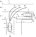
まず、図2を参照して、自車両から比較的遠い位置を交差車両が走行しているケースにおける経路候補について説明する。図2は、実施形態に係る経路候補の説明図である。 First, with reference to FIG. 2, route candidates in the case where the intersecting vehicle is traveling at a position relatively far from the own vehicle will be described. FIG. 2 is an explanatory diagram of route candidates according to the embodiment.
自車線90は、交差点7において交差道路93と交差している。交差道路93は、自車線90が接続されている第1交差車線91と、第1交差車線91よりも自車線90から離れた位置に設けられている第2交差車線92と、を有している。第1交差車線91と第2交差車線92とは、区画線L1により区画されている。第1交差車線91は、車両が図2の左方向に走行するために設けられており、第2交差車線92は、第1交差車線91の対向車線である。第1交差車線91及び第2交差車線92は、本発明に係る「交差車線」の一例である。
自車両1は、自車線90を走行し、交差点7に進入する。自車両1は、交差点7において右折しながら第1交差車線91を通過し、第2交差車線92に合流しようとしている。一方、交差車両8は、速度V(絶対値)で第1交差車線91を走行し、交差点7に進入しようとしている。つまり、交差車両8は、自車両1の右方から自車両1に接近している。
The
このような状況において、コントローラ10は、自車両1と交差車両8との衝突を回避し得る複数の経路候補(つまり、実際に自車両1を走行させる目標経路となり得る候補)を設定する。例えば、コントローラ10は、ステートラティス法を用いた経路探索により、自車両1の前端1aから、自車両1の進行方向に向かって枝分かれしながら延びる複数の経路候補を設定する。
In such a situation, the
図2は、コントローラ10が設定した経路候補R1~R3を示している。経路候補R1~R3は、いずれも、自車両1の前端1aから第1交差車線91を介して第2交差車線92まで、予め規定された値(例えば、100m)だけ延びている。コントローラ10は、例えば、自車線90及び交差道路93上に、所定間隔(例えば、10cm)で複数の仮想のグリッド点(不図示)を設定するとともに、当該複数のグリッド点を繋ぐように延びる経路候補R1~R3を設定する。
FIG. 2 shows route candidates R1 to R3 set by the
また、コントローラ10は、仮想壁Wを設定する。仮想壁Wは、自車両1と交差車両8との衝突を回避するために設定された仮想的な対象物である。仮想壁Wは、自車両1と交差車両8との間に設定され、第1交差車線91の端部91aに沿って交差車両8の進行方向に延びている。第1交差車線91の端部91aは、例えば、第1交差車線91に設けられた縁石や白線に基づいて定められる。コントローラ10は、第1交差車線91のうち自車線90が接続されている部分には、端部91aに沿う仮想の延長線L2を設定し、当該延長線L2に沿うように仮想壁Wを設定する。仮想壁Wは、自車両1側の前端Waと交差車両8側の後端Wbとによって規定される長さ(つまり前端Waから後端Wbまでの長さ)Xを有している。後端Wbは、交差車両8の後端8bに対応する位置に設定されている。
Also, the
コントローラ10は、自車両1が右折しながら第1交差車線91を通過し終えるのに要する時間に応じて、仮想壁Wの長さXを設定する。具体的には、コントローラ10は、まず、自車両1が第1交差車線91を通過し終えるのに要する時間(換言すれば、自車両1が第2交差車線92に合流し終えるのに要する時間)teを算出する。より詳しくは、コントローラ10は、まず、自車両1の後端1bが区画線L1に到達するのに要する大まかな時間を算出し、当該時間を、自車両1が第1交差車線91を通過し終えるのに要する時間teとする。
The
コントローラ10は、「X=V×te」により表される式に基づいて、長さXを設定する。つまり、コントローラ10は、仮想壁Wの長さXを、自車両1が第1交差車線91を通過し終えるのに要する時間teと、交差車両8の速度Vとに応じたものに設定する。
The
また、コントローラ10は、仮想壁Wを、交差車両8と第1交差車線91の端部91aとの間に設定する。詳細には、仮想壁Wは、交差車両8の側面部8cから第1交差車線91の端部91aまで至る幅Yを有している。
Also, the
コントローラ10は、このような形状を有する仮想壁Wを、交差車両8の進行に伴って移動させる(換言すると交差車両8と共に自車両1に向かって進行させる)。コントローラ10は、この仮想壁Wに基づいて複数の経路候補を設定する。
The
具体的には、コントローラ10は、仮想壁Wを通過しないように複数の経路候補を設定する。図2に示されるように、交差車両8が自車両1から十分離れている場合、自車両1の前端1aから延びている経路候補R1~R3は、全て仮想壁Wと交差しない。これは、自車両1が経路候補R1~R3のいずれに沿って走行する場合も、自車両1が交差車両8と衝突する可能性が比較的低いことを意味する。これより、自車両1の前端1aから予め規定された値だけ延びる経路候補R1~R3が設定される。
Specifically, the
コントローラ10は、経路候補R1~R3の経路コストを計算する。詳細には、コントローラ10は、まず、経路候補R1~R3のそれぞれに沿って複数のサンプリング点を設定する(不図示)。複数のサンプリング点は、経路候補R1~R3上に、互いに間隔を空けて配置される。
The
次に、コントローラ10は、各サンプリング点における経路コストを計算する。さらに、コントローラ10は、経路候補毎に、その経路候補に沿って設定されたサンプリング点における経路コストを合算するとともに、当該合算値をその経路候補の全長で除算する。コントローラ10は、当該除算により得られる値を、その経路候補の経路コストとする。
コントローラ10は、経路候補R1~R3から、経路コストが最小である経路候補を選択し、目標経路として設定する。コントローラ10は、当該目標経路に沿って、第2交差車線92に合流する自車両1の走行を支援する。
The
次に、図3を参照して、自車両から比較的近い位置を交差車両が走行しているケースにおける経路候補について説明する。図3は、実施形態に係る経路候補の説明図である。上述したケースと同一の構成や処理については、その説明を適宜省略する。 Next, with reference to FIG. 3, route candidates in the case where the intersecting vehicle is traveling relatively close to the own vehicle will be described. FIG. 3 is an explanatory diagram of route candidates according to the embodiment. Descriptions of the same configurations and processes as in the case described above will be omitted as appropriate.
仮想壁Wは、交差車両8と共に自車両1に接近する。図3に示される例では、仮想壁Wが自車線90の一部を覆う程度に、仮想壁Wが自車両1に接近している。
The virtual wall W approaches the
コントローラ10は、図2と同様に、自車両1の前端1aから、自車両1の進行方向に向かって枝分かれしながら延びる複数の経路候補を設定する。コントローラ10が経路候補R1を設定しようとすると、経路候補R1は、仮想壁Wと交差することなく延びることができる。これは、自車両1が経路候補R1に沿って走行する場合、自車両1が交差車両8と衝突する可能性が比較的低いことを意味する。これより、コントローラ10は、予め規定された値だけ延びる経路候補R1を設定する。
The
これに対し、コントローラ10が経路候補R2,R3を設定しようとすると、経路候補R2,R3は、いずれも仮想壁Wと交差する。これは、自車両1が経路候補R2,R3に沿って走行する場合、自車両1が交差車両8と衝突する可能性が比較的高いことを意味する。この場合、コントローラ10は、自車両1の前端1aから、仮想壁Wのやや手前の点P2,P3まで延びる経路候補R2s,R3sを設定する。経路候補R2s,R3sは、自車両1を点P2,P3まで走行させ、点P2,P3で停止させるために用いられる。経路候補R2s,R3sは、経路候補R2,R3の一部であり、図3は、経路候補R2,R3のうち実際には設定されない部分を破線で示している。したがって、コントローラ10が経路候補R2s,R3sを設定する際の計算負荷は、経路候補R2,R3を設定する際の計算負荷と比べて小さい。
On the other hand, when the
また、コントローラ10は、経路候補R1,R2s,R3sの経路コストを計算する。経路候補R2s,R3sの全長は経路候補R2,R3よりも短いため、経路候補R2s,R3sに沿って設定されるサンプリング点の数は、経路候補R2,R3に沿って設定されるサンプリング点の数よりも少ない。したがって、コントローラ10が経路候補R2s,R3sの経路コストを計算する際の負荷は、経路候補R2,R3の経路コストを計算する際の負荷と比べて小さい。
The
コントローラ10は、経路候補R1,R2s,R3sから、経路コストが最小である経路候補を選択し、目標経路として設定する。コントローラ10は、自車両1が当該目標経路に沿って第2交差車線92に合流する際の走行や、点P2,P3で停止する際の走行を支援する。
The
上述した経路候補の設定方法は、自車両1が交差点7において左折しようとしている場合にも適用できる。具体的には、自車両1が交差点7において左折しようとしている場合、自車両1が第1交差車線91に合流し終えるのに要する時間を算出し、当該時間を、上述した時間teとする。詳細には、コントローラ10は、左折している自車両1の後端1bが、延長線L2に到達するのに要する大まかな時間を算出し、当該時間を、自車両1が第1交差車線91に合流し終えるのに要する時間teとする。そして、コントローラ10は、「X=V×te」により表される式に基づいて仮想壁Wの長さXを設定し、仮想壁Wとの交差の有無に基づいて、複数の経路候補を設定する。
The route candidate setting method described above can also be applied when the
次に、図4を参照して、コントローラ10が実行する処理について説明する。図4は、実施形態に係るコントローラ10が実行する処理を示すフローチャートである。コントローラ10は、所定の周期(例えば100ms毎)で、当該フローチャートに係る処理を繰り返し実行する。
Next, processing executed by the
まず、ステップS11において、コントローラ10は、上述した複数のセンサ及びスイッチから各種情報を取得する。具体的には、コントローラ10は、カメラ21、レーダ22、車速センサ23、加速度センサ24、ヨーレートセンサ25、操舵角センサ26、アクセルセンサ27、ブレーキセンサ28、測位装置29、ナビゲーション装置30、通信装置31、操作装置32から入力された信号に基づき、各種情報を取得する。
First, in step S11, the
次いで、ステップS12において、コントローラ10は、自車両1が交差点に進入しようとしているか否かを判定する。具体的には、コントローラ10は、カメラ21から入力された信号(画像データに対応する)や、ナビゲーション装置30から入力された信号(地図情報及び現在車両位置情報に対応する)や、通信装置31から入力された信号(路車間通信に対応する)に基づいて、自車両1の近傍且つ自車両1の進行方向に、交差点が存在するか否かを判定する。自車両1が交差点に進入しようとしていると判定した場合(ステップS12:Yes)、コントローラ10は、ステップS13に進む。これに対して、自車両1が交差点に進入しようとしていると判定されなかった場合(ステップS12:No)、コントローラ10は、本フローチャートに示す一連のルーチンを抜ける。
Next, in step S12, the
次いで、ステップS13において、コントローラ10は、交差車線を走行しながら自車両1に接近する交差車両8が存在するか否かを判定する。具体的には、コントローラ10は、カメラ21から入力された信号(画像データに対応する)や、レーダ22から入力された信号や、通信装置31から入力された信号(車車間通信に対応する信号)などに基づき、自車両1に接近する交差車両8を検出するための処理を実行する。その結果、自車両1に接近する交差車両8が検出された場合、コントローラ10は、交差車両8が存在すると判定し(ステップS13:Yes)、ステップS14に進む。これに対して、自車両1に接近する交差車両8が検出されなかった場合、コントローラ10は、交差車両8が存在しないと判定し(ステップS13:No)、本フローチャートに示す一連のルーチンを抜ける。
Next, in step S13, the
次いで、ステップS14において、コントローラ10は、時間teを算出する。上述したように、自車両1が右折する場合、時間teは、自車両1が、交差車両8が走行している第1交差車線91を通過し終えるのに要する時間である。また、自車両1が左折する場合、時間teは、自車両1が、交差車両8が走行している第1交差車線91に合流し終えるのに要する時間である。
Next, in step S14, the
次いで、ステップS15において、コントローラ10は、交差車両8の速度V、及び、時間teに基づき、仮想壁Wを設定する。具体的には、コントローラ10は、交差車両8の後端8bから、交差車両8の進行方向に長さXだけ延び、幅Yを有する仮想壁Wを設定する。
Next, in step S15, the
ステップS16は、経路候補の設定(ステップS16a~S16d)と、経路コストの計算(ステップS16e)と、を含んでいる。 Step S16 includes route candidate setting (steps S16a to S16d) and route cost calculation (step S16e).
ステップS16aにおいて、コントローラ10は、1つの経路候補の設定を開始する。具体的には、コントローラ10は、自車両1の前端1aから、1つの経路候補を、自車両1の進行方向に向かって徐々に延ばし始める。
In step S16a, the
次いで、ステップS16bにおいて、コントローラ10は、延ばしている経路候補が仮想壁Wと交差しているか否かを判定する。経路候補が仮想壁Wと交差していると判定されなかった場合(ステップS16b:Yes)、コントローラ10は、ステップS16cに進む。
Next, in step S16b, the
次いで、ステップS16cにおいて、コントローラ10は、経路候補の長さが、予め規定された値に達したか否かを判定する。経路候補の長さが当該値に達したと判定した場合(ステップS16c:Yes)、コントローラ10は、経路候補を延ばすことを止め、ステップS16eに進む。一方、経路候補の長さが、予め規定された値に達したと判定されなかった場合(ステップS16c:No)、コントローラ10は、ステップS16bに戻り、経路候補をさらに延ばす。
Next, in step S16c, the
これに対して、ステップS16bにおいて、経路候補が仮想壁Wと交差していると判定された場合(ステップS16b:Yes)、コントローラ10は、ステップS16dに進む。
On the other hand, if it is determined in step S16b that the route candidate intersects the virtual wall W (step S16b: Yes), the
次いで、ステップS16dにおいて、コントローラ10は、仮想壁Wの手前まで延びる経路候補を設定する。具体的には、コントローラ10は、仮想壁Wの手前の点(上述した点P2,P3に対応する)を終点とするように経路候補を設定する。
Next, in step S16d, the
次いで、ステップS16eにおいて、コントローラ10は、経路候補の経路コストを計算する。経路コストには、自車両1の速度、加速度、横加速度や、経路変化率、障害物等に関するコストが含まれる。これらのコストは適宜設定することができる。概略的には、経路コストは、移動コストと安全コストを含む。例えば、直線経路を走行する場合は、移動距離が短いため移動コストが小さくなるが、障害物等を回避する経路を走行する場合は、移動距離が長くなるため移動コストが大きくなる。また、横加速度が大きくなるほど移動コストは増大する。上述したように、コントローラ10は、複数のサンプリング点を用いて得られる値を、その経路候補の経路コストとしてメモリ12に格納する。
Next, in step S16e, the
コントローラ10は、このようなステップS16の処理を、所定数の経路候補が設定されるまで実行する。この結果、各経路候補の経路コストがメモリ12に格納される。
The
次に、ステップS17で、コントローラ10は、目標経路を設定する。詳細には、コントローラ10は、メモリ12に格納されている各経路候補の経路コストに基づいて、経路コストが最小である経路候補を選択し、当該経路候補を目標経路に設定する。
Next, in step S17, the
次に、ステップS18で、コントローラ10は、目標経路に沿って自車両1が走行するように、エンジン制御装置51、ブレーキ制御装置52、及びステアリング制御装置53に対して制御信号を送信する。当該制御信号は、目標経路の各サンプリング点に設定された自車両1の速度制御及び操舵制御の制御量に基づいて生成される。
Next, in step S18, the
次に、実施形態に係る作用及び効果について説明する。 Next, functions and effects according to the embodiment will be described.
この構成によれば、コントローラ10は仮想壁Wを設定する。仮想壁Wは、交差車両8の進行に伴って移動し、且つ交差車両8の進行方向に延びている。コントローラ10は、このような仮想壁Wを自車両1と交差車両8との間に設定し、仮想壁Wを通過しないように複数の経路候補を設定する。これにより、自車両1と交差車両8との衝突を確実に回避するように自車両1を走行させるための複数の経路候補を設定することができる。また、コントローラ10は、仮想壁Wを通過する経路候補を設定しないため、その計算負荷を軽減することができる。すなわち、本発明によれば、自車両1と交差車両8との衝突を回避しつつ、計算負荷を軽減可能な経路候補を設定することができる。
According to this configuration, the
また、コントローラ10は、自車両1から仮想壁Wの手前まで延びる経路候補を設定するよう構成されている。この構成によれば、自車両1を仮想壁Wの手前で停止させるための経路候補を含め、多様な経路候補を設定することができる。この結果、より確実に交差車両8との衝突を回避可能な経路候補を設定することができる。
Further, the
また、コントローラ10は、自車両1が第1交差車線91を通過し終えるのに要する時間te(自車両1が右折する場合)、又は、自車両1が第1交差車線91に合流し終えるのに要する時間te(自車両1が左折する場合)に応じた長さXを有する仮想壁Wを設定するよう構成されている。この構成によれば、コントローラ10は、仮想壁Wの長さXを、交差車両8との衝突を回避できる位置まで自車両1が移動し終えるのに要する時間に応じたものに設定することができる。このような長さを有する仮想壁Wを設定することにより、自車両1と交差車両8との衝突を確実に回避することができる。
The
また、コントローラ10は、自車両1が第1交差車線91を通過し終えるのに要する時間te(自車両1が右折する場合)、又は、自車両1が第1交差車線91に合流し終えるのに要する時間te(自車両1が左折する場合)を、交差車両8の速度Vに対して乗算することにより得られる距離に基づいて、仮想壁Wの長さXを設定するよう構成されている。この構成によれば、コントローラ10は、仮想壁Wの長さXを、交差車両8との衝突を回避できる位置まで自車両1が移動し終えるのに要する時間と、交差車両8の速度Vとに応じたものに設定することができる。このような長さXを有する仮想壁Wを設定することにより、自車両1と交差車両8との衝突を確実に回避することができる。
The
上述した実施形態に係るコントローラ10は、T字形状を呈する交差点7において自車両1の走行を支援している。しかしながら、本発明はこの形態に限定されるものではない。例えば、本発明は、十字形状等を呈する交差点に進入する自車両に対しても、適用することができる。
The
また、上述した実施形態に係るコントローラ10は、ステートラティス法を用いた経路探索により、複数の経路候補を設定している。しかしながら、本発明はこの形態に限定されるものではない。例えば、本発明は、ポテンシャル法、スプライン補間関数、Aスター、RRT等、他の手法を用いて経路候補を設定する車両制御装置にも、適用することができる。
Further, the
1 自車両
8 交差車両
10 コントローラ
21 カメラ(交差車両検出センサ)
22 レーダ(交差車両検出センサ)
31 通信装置(交差車両検出センサ)
90 自車線
91 第1交差車線(交差車線)
100 車両制御装置
R1~R3 経路候補
W 仮想壁
1 own vehicle 8
22 radar (crossing vehicle detection sensor)
31 communication device (crossing vehicle detection sensor)
90
100 vehicle control device R1 to R3 route candidate W virtual wall
Claims (3)
自車線を走行している自車両が交差点に進入するとき、該交差点において該自車線と交差している車線を交差車線と定義し、該交差車線を走行している車両を交差車両と定義すると、
前記交差車線を走行しながら前記自車両に接近する前記交差車両を検出するよう構成された交差車両検出センサと、
前記自車両から延びる複数の経路候補を設定し、該複数の経路候補に基づいて前記自車両の走行を支援するよう構成されたコントローラと、を有し、
前記コントローラは、前記交差車両の進行に伴って移動し、且つ前記交差車両の進行方向に延びる仮想壁を前記自車両と前記交差車両との間に設定して、該仮想壁を通過しないように前記複数の経路候補を設定するとともに、前記自車両から前記仮想壁の手前まで延びる前記経路候補を設定するよう構成されている、
ことを特徴とする車両制御装置。 A vehicle control device for supporting running of a vehicle,
When a vehicle traveling in its own lane enters an intersection, the lane that intersects the own lane at the intersection is defined as an intersecting lane, and the vehicle traveling in the intersecting lane is defined as an intersecting vehicle. ,
an intersecting vehicle detection sensor configured to detect the intersecting vehicle approaching the own vehicle while traveling in the intersecting lane;
a controller configured to set a plurality of route candidates extending from the own vehicle and to support travel of the own vehicle based on the plurality of route candidates;
The controller moves along with the progress of the crossing vehicle and sets a virtual wall extending in the traveling direction of the crossing vehicle between the own vehicle and the crossing vehicle so as not to pass through the virtual wall. It is configured to set the plurality of route candidates and to set the route candidate extending from the own vehicle to the front of the virtual wall .
A vehicle control device characterized by:
Priority Applications (4)
| Application Number | Priority Date | Filing Date | Title |
|---|---|---|---|
| JP2019082578A JP7197832B2 (en) | 2019-04-24 | 2019-04-24 | vehicle controller |
| US16/816,279 US20200339114A1 (en) | 2019-04-24 | 2020-03-12 | Vehicle control device, method and computer program product |
| EP20162747.8A EP3730368A1 (en) | 2019-04-24 | 2020-03-12 | Vehicle control device, method and computer program product |
| CN202010198952.4A CN111845731A (en) | 2019-04-24 | 2020-03-20 | Vehicle control device |
Applications Claiming Priority (1)
| Application Number | Priority Date | Filing Date | Title |
|---|---|---|---|
| JP2019082578A JP7197832B2 (en) | 2019-04-24 | 2019-04-24 | vehicle controller |
Publications (2)
| Publication Number | Publication Date |
|---|---|
| JP2020179731A JP2020179731A (en) | 2020-11-05 |
| JP7197832B2 true JP7197832B2 (en) | 2022-12-28 |
Family
ID=69810674
Family Applications (1)
| Application Number | Title | Priority Date | Filing Date |
|---|---|---|---|
| JP2019082578A Active JP7197832B2 (en) | 2019-04-24 | 2019-04-24 | vehicle controller |
Country Status (4)
| Country | Link |
|---|---|
| US (1) | US20200339114A1 (en) |
| EP (1) | EP3730368A1 (en) |
| JP (1) | JP7197832B2 (en) |
| CN (1) | CN111845731A (en) |
Families Citing this family (3)
| Publication number | Priority date | Publication date | Assignee | Title |
|---|---|---|---|---|
| DE112018001106T5 (en) * | 2017-03-02 | 2019-11-21 | Panasonic Intellectual Property Management Co., Ltd. | Driver assistance system, driver assistance device and driver assistance system using this method |
| JP7036857B2 (en) * | 2020-03-27 | 2022-03-15 | 本田技研工業株式会社 | Vehicle and its control device |
| DE102020209353A1 (en) * | 2020-07-24 | 2022-01-27 | Ford Global Technologies, Llc | Controlling a vehicle considering the sensor range |
Citations (2)
| Publication number | Priority date | Publication date | Assignee | Title |
|---|---|---|---|---|
| JP2005141557A (en) | 2003-11-07 | 2005-06-02 | Nissan Motor Co Ltd | Display system for vehicle |
| JP2016009440A (en) | 2014-06-26 | 2016-01-18 | 株式会社デンソー | Collision mitigation device and collision mitigation program |
Family Cites Families (10)
| Publication number | Priority date | Publication date | Assignee | Title |
|---|---|---|---|---|
| JP2006256493A (en) * | 2005-03-17 | 2006-09-28 | Advics:Kk | Traveling support device for vehicle |
| JP4654796B2 (en) * | 2005-06-29 | 2011-03-23 | トヨタ自動車株式会社 | Vehicle driving support device |
| JP5897787B2 (en) * | 2010-03-30 | 2016-03-30 | トヨタ自動車株式会社 | Driving support device and driving support method |
| CN103842229A (en) | 2011-10-03 | 2014-06-04 | 丰田自动车株式会社 | Vehicle driving support system |
| JP6350385B2 (en) * | 2015-05-13 | 2018-07-04 | トヨタ自動車株式会社 | Driving assistance device |
| JP6347262B2 (en) * | 2016-02-12 | 2018-06-27 | マツダ株式会社 | Vehicle control device |
| JP6668895B2 (en) * | 2016-04-01 | 2020-03-18 | 株式会社デンソー | Driving support device |
| JP6380919B2 (en) * | 2016-09-01 | 2018-08-29 | マツダ株式会社 | Vehicle control device |
| EP4230964A1 (en) * | 2017-01-12 | 2023-08-23 | Mobileye Vision Technologies Ltd. | Navigation based on vehicle activity |
| JP2018173728A (en) * | 2017-03-31 | 2018-11-08 | パナソニックIpマネジメント株式会社 | Automatic driving control method, automatic driving controller using the same, and program |
-
2019
- 2019-04-24 JP JP2019082578A patent/JP7197832B2/en active Active
-
2020
- 2020-03-12 US US16/816,279 patent/US20200339114A1/en not_active Abandoned
- 2020-03-12 EP EP20162747.8A patent/EP3730368A1/en not_active Withdrawn
- 2020-03-20 CN CN202010198952.4A patent/CN111845731A/en active Pending
Patent Citations (2)
| Publication number | Priority date | Publication date | Assignee | Title |
|---|---|---|---|---|
| JP2005141557A (en) | 2003-11-07 | 2005-06-02 | Nissan Motor Co Ltd | Display system for vehicle |
| JP2016009440A (en) | 2014-06-26 | 2016-01-18 | 株式会社デンソー | Collision mitigation device and collision mitigation program |
Also Published As
| Publication number | Publication date |
|---|---|
| EP3730368A1 (en) | 2020-10-28 |
| US20200339114A1 (en) | 2020-10-29 |
| JP2020179731A (en) | 2020-11-05 |
| CN111845731A (en) | 2020-10-30 |
Similar Documents
| Publication | Publication Date | Title |
|---|---|---|
| EP3730361A1 (en) | Vehicle control device, method and computer program product | |
| JP6630267B2 (en) | Vehicle control device | |
| JP6809890B2 (en) | Vehicle control device | |
| CN111824088B (en) | Vehicle control device | |
| CN111824089B (en) | Vehicle control device | |
| JP6460579B2 (en) | Driving support control device | |
| JP7197832B2 (en) | vehicle controller | |
| CN111845670B (en) | Vehicle control device | |
| JP6985176B2 (en) | Vehicle control device | |
| EP3725629A1 (en) | Vehicle control device | |
| JP7239877B2 (en) | vehicle controller | |
| JP7231884B2 (en) | vehicle controller | |
| JP7332996B2 (en) | vehicle controller | |
| JP7262702B2 (en) | vehicle controller | |
| JP7276690B2 (en) | vehicle controller | |
| JP7226304B2 (en) | vehicle controller | |
| JP7258284B2 (en) | vehicle controller | |
| JP7337328B2 (en) | vehicle controller | |
| JP2020163968A (en) | Vehicle drive assisting system | |
| JP2020163974A (en) | Vehicle drive assisting system | |
| JP7393722B2 (en) | Vehicle driving support system | |
| JP2020179730A (en) | Vehicle control apparatus | |
| JP2024039134A (en) | Vehicle control device and vehicle control method | |
| JP2021105909A (en) | Vehicle control device | |
| JP2020163969A (en) | Vehicle drive assisting system |
Legal Events
| Date | Code | Title | Description |
|---|---|---|---|
| A621 | Written request for application examination |
Free format text: JAPANESE INTERMEDIATE CODE: A621 Effective date: 20211021 |
|
| A977 | Report on retrieval |
Free format text: JAPANESE INTERMEDIATE CODE: A971007 Effective date: 20220817 |
|
| A131 | Notification of reasons for refusal |
Free format text: JAPANESE INTERMEDIATE CODE: A131 Effective date: 20220907 |
|
| A521 | Request for written amendment filed |
Free format text: JAPANESE INTERMEDIATE CODE: A523 Effective date: 20221102 |
|
| TRDD | Decision of grant or rejection written | ||
| A01 | Written decision to grant a patent or to grant a registration (utility model) |
Free format text: JAPANESE INTERMEDIATE CODE: A01 Effective date: 20221116 |
|
| A61 | First payment of annual fees (during grant procedure) |
Free format text: JAPANESE INTERMEDIATE CODE: A61 Effective date: 20221129 |
|
| R150 | Certificate of patent or registration of utility model |
Ref document number: 7197832 Country of ref document: JP Free format text: JAPANESE INTERMEDIATE CODE: R150 |