JP7192004B2 - robot controller - Google Patents
robot controller Download PDFInfo
- Publication number
- JP7192004B2 JP7192004B2 JP2021034249A JP2021034249A JP7192004B2 JP 7192004 B2 JP7192004 B2 JP 7192004B2 JP 2021034249 A JP2021034249 A JP 2021034249A JP 2021034249 A JP2021034249 A JP 2021034249A JP 7192004 B2 JP7192004 B2 JP 7192004B2
- Authority
- JP
- Japan
- Prior art keywords
- wall
- housing
- cover
- fan
- robot controller
- Prior art date
- Legal status (The legal status is an assumption and is not a legal conclusion. Google has not performed a legal analysis and makes no representation as to the accuracy of the status listed.)
- Active
Links
Images


Landscapes
- Manipulator (AREA)
Description
本発明は、ロボットコントローラに関し、例えば、ロボットを制御するロボットコントローラに関する。 The present invention relates to a robot controller, and for example, to a robot controller that controls a robot.
ロボットを制御するコントローラとして、特許文献1に示すコントローラが知られている。このコントローラは、産業用ロボットのモータに電力を供給するパワー回路基板と、パワー回路基板を収容する金属製のケース本体と、ケース本体の面壁に設けられたファンとを備えている。 A controller disclosed in Patent Document 1 is known as a controller for controlling a robot. This controller includes a power circuit board that supplies power to the motor of the industrial robot, a metal case body that houses the power circuit board, and a fan that is provided on the face wall of the case body.
上記特許文献1に示すコントローラのようなロボットを制御するコントローラは、一般的な家電製品と比べて、粉塵及び切削液ミスト等が浮遊した環境下で使用されることがある等の特殊性を有している。しかしながら、上記特許文献1に示すコントローラでは、ケース本体の面壁に設けられたファンが外気をケース本体内に導入するため、使用環境によっては粉塵及び液体を含む外気がケース本体内に入り、この粉塵及び液体によりケース本体内の電子部品に悪影響が発生するおそれがある。 A controller for controlling a robot, such as the controller disclosed in Patent Document 1, has special features such as being used in an environment where dust, cutting fluid mist, etc. doing. However, in the controller disclosed in Patent Document 1, the fan provided on the face wall of the case main body introduces outside air into the case main body. Also, the liquid may adversely affect the electronic components in the case body.
これに対して、ケース本体の全体を密閉容器の中に収容して、密閉容器によって外気からケースを遮断することも考えられる。ただし、これでは、コントローラが大型化してしまう。 On the other hand, it is also conceivable to house the entire case main body in a closed container, and isolate the case from the outside air by the closed container. However, this makes the controller larger.
本発明はこのような課題を解決するためになされたものであり、大型化を低減しつつ、粉塵等による悪影響を軽減可能なロボットコントローラを提供することを目的としている。 SUMMARY OF THE INVENTION The present invention has been made to solve such problems, and it is an object of the present invention to provide a robot controller capable of reducing adverse effects caused by dust and the like while reducing the increase in size.
本発明のある態様に係るロボットコントローラは、ロボットのモータを制御するコントローラであって、熱を発生する発熱部品を収容する筐体と、前記筐体の壁に開口する通気孔と、前記筐体内において前記通気孔を介して導入した空気を前記発熱部品に送るファンと、前記通気孔を被覆可能な蓋部品と、を備えている。 A robot controller according to an aspect of the present invention is a controller for controlling a motor of a robot, comprising: a housing containing a heat-generating component that generates heat; a vent opening in a wall of the housing; a fan for sending the air introduced through the ventilation hole to the heat-generating component; and a lid member capable of covering the ventilation hole.
この構成によれば、蓋部品を取り外すことにより筐体を開放して用いることができ、蓋部品を取り付けることにより筐体を密閉して用いることができる。この密閉した状態では、通気孔を介して筐体内に導入される粉塵等による筐体内の電子部品への悪影響を軽減することができる。また、密閉性が確保されている他の部分は被覆する必要がなく、ロボットコントローラの大型化を低減することができる。 According to this configuration, the housing can be used with the housing opened by removing the lid component, and the housing can be used with the housing closed by attaching the lid component. In this closed state, it is possible to reduce the adverse effects of dust and the like introduced into the housing through the ventilation holes on the electronic components within the housing. In addition, it is not necessary to cover the other parts where airtightness is ensured, so that the size of the robot controller can be reduced.
ロボットコントローラでは、前記壁は第1壁であって、前記ファンは第1ファンであって、前記発熱部品が固定された前記筐体の第2壁は熱伝導率が高い材料で形成され、前記第2壁を覆い、開口部を有するカバーと、前記開口部に対向して配置され、前記カバー内に前記開口部を介して空気を送る第2ファンと、をさらに備えていてもよい。この構成によれば、第2壁が第2ファンにより送られた空気により冷却され、この第2壁に固定される発熱部品が冷却され、発熱部品の熱による他の部品への悪影響を軽減することができる。 In the robot controller, the wall is a first wall, the fan is a first fan, the second wall of the housing to which the heat-generating component is fixed is formed of a material with high thermal conductivity, and the A cover covering the second wall and having an opening may further be provided, and a second fan positioned opposite the opening for sending air into the cover through the opening. According to this configuration, the second wall is cooled by the air sent by the second fan, and the heat-generating components fixed to the second wall are cooled, thereby reducing the adverse effects of the heat of the heat-generating components on other components. be able to.
ロボットコントローラでは、前記第2壁の外面に脱着可能に装着されるヒートシンクと、さらに備え、前記カバーは前記ヒートシンクを覆い、前記第2ファンは前記ヒートシンクに空気を送っていてもよい。この構成によれば、ヒートシンクが第2ファンにより送られた空気により冷却され、このヒートシンクによって第2壁を介して固定される発熱部品が冷却され、発熱部品の熱による他の部品への悪影響を軽減することができる。 The robot controller may further include a heat sink detachably attached to the outer surface of the second wall, the cover covering the heat sink, and the second fan sending air to the heat sink. According to this configuration, the heat sink is cooled by the air sent by the second fan, and the heat-generating component fixed via the second wall is cooled by this heat sink, thereby preventing the heat from the heat-generating component from adversely affecting other components. can be mitigated.
ロボットコントローラでは、前記第2ファンは、前記蓋部品及び前記開口部に対向して配置され、前記蓋部品及び前記カバー内に空気を送ってもよい。この構成によれば、第2ファンにより送られる空気によって蓋部品及びその近傍の空気が冷却されるため、蓋部品の近傍に配置される第1ファンが冷却された空気を発熱部品に送り、発熱部品を効率的に冷却することができる。また、蓋部品を専用に冷却するファンを用いないため、ロボットコントローラの大型化を抑制することができる。 In the robot controller, the second fan may be positioned opposite the lid component and the opening to force air into the lid component and the cover. According to this configuration, since the air sent by the second fan cools the lid component and the air in the vicinity thereof, the first fan arranged in the vicinity of the lid component sends the cooled air to the heat-generating component, thereby generating heat. The parts can be efficiently cooled. In addition, since a fan exclusively for cooling the lid component is not used, it is possible to suppress an increase in the size of the robot controller.
ロボットコントローラでは、前記第2ファンを前記筐体に脱着可能に装着する装着部をさらに備え、前記蓋部品は前記装着部に取り付けられていてもよい。この構成によれば、第2ファンを筐体に装着すると同時に、装着部に取り付けられた蓋部品を筐体に取り付けられるため、蓋部品が通気孔を被覆することができる。 The robot controller may further include a mounting section for detachably mounting the second fan to the housing, and the lid component may be mounted on the mounting section. According to this configuration, since the lid component attached to the mounting portion can be attached to the casing at the same time that the second fan is attached to the casing, the lid component can cover the air vent.
ロボットコントローラでは、前記筐体は、直方体形状であって、前記第1壁、前記第2壁、及び前記第1壁に対向する第3壁を含む本体と、前記第2壁に対向し且つ前記本体に脱着可能に設けられる第4壁とを有していてもよい。この構成によれば、第4壁を取り外すことにより、本体を開放して、本体内の電子部品をメンテナンスすることができる。また、第1壁及び第4壁が外に露出した状態で第2壁を下にする横置き、及び、第1~第4壁以外の壁を下にする縦置きにすることができる。 In the robot controller, the housing has a rectangular parallelepiped shape, and includes a main body including the first wall, the second wall, and a third wall facing the first wall, and the housing facing the second wall and facing the first wall. and a fourth wall detachably provided on the main body. According to this configuration, by removing the fourth wall, the main body can be opened for maintenance of electronic components in the main body. In addition, it can be placed horizontally with the second wall facing down while the first wall and the fourth wall are exposed to the outside, or can be placed vertically with the walls other than the first to fourth walls facing down.
ロボットコントローラでは、前記第2ファンに電力を供給する電力供給コネクタが前記第1壁の外面に設けられていてもよい。この構成によれば、第1壁の外側に配置した第2ファンを電力供給コネクタに簡単に接続することができる。 In the robot controller, a power supply connector for supplying power to the second fan may be provided on the outer surface of the first wall. With this configuration, the second fan arranged outside the first wall can be easily connected to the power supply connector.
本発明は、以上に説明した構成を有し、大型化を低減しつつ、粉塵等による悪影響を軽減可能なロボットコントローラを提供することができるという効果を奏する。 Advantageous Effects of Invention The present invention has the configuration described above, and has the effect of being able to provide a robot controller capable of reducing the adverse effects of dust and the like while reducing the increase in size.
本発明の上記目的、他の目的、特徴及び利点は、添付図面を参照の下、以下の好適な実施態様の詳細な説明から明らかにされる。 The above object, other objects, features and advantages of the present invention will become apparent from the following detailed description of preferred embodiments with reference to the accompanying drawings.
以下、本発明の実施の形態を、図面を参照しながら具体的に説明する。なお、以下では全ての図面を通じて同一又は相当する要素には同一の参照符号を付して、その重複する説明を省略する。また、各図において上、下、左、右、前、後の各方向を規定しているが、ロボットコントローラの方向はこれに限定されない。 BEST MODE FOR CARRYING OUT THE INVENTION Hereinafter, embodiments of the present invention will be specifically described with reference to the drawings. In the following description, the same reference numerals are given to the same or corresponding elements throughout all the drawings, and duplicate descriptions thereof will be omitted. In addition, although the directions of up, down, left, right, front, and back are defined in each drawing, the directions of the robot controller are not limited to these.
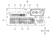
実施の形態に係るロボットコントローラ10の構成について、図1~図3を参照して説明する。ロボットコントローラ10は、ロボット(図示せず)のモータを制御する装置である。図1に示すように、ロボットコントローラ10は、電子部品を収容する筐体20を備えている。
A configuration of a
筐体20は、例えば、鉄よりも熱伝導率が良い材料により形成されており、この材料としては例えば、アルミニウム等の金属が挙げられる。筐体20は、例えば、金型に溶融した金属を圧入して形成するダイカストにより形成されている。
The
筐体20は、内部空間を有するケースであって、例えば、直方体形状である。筐体20は、第1壁21(前側壁)、第2壁22(下側壁)、第3壁23(後側壁)、第4壁24(上側壁)、第5壁25(左側壁)及び第6壁26(右側壁)を有している。これらの壁は、矩形の平板形状である。
The
この第1壁21、第2壁22、第3壁23、第5壁25及び第6壁26により本体が構成されており、第4壁24は本体に対して脱着可能に設けられている。例えば、第4壁24に貫通孔(図示せず)が設けられ、第3壁23、第5壁25及び第6壁26の各壁の上面に螺旋溝が形成された挿入孔(図示せず)が設けられている。この貫通孔を介して挿入孔にビスを挿入して締結することにより、第4壁24は本体に対して取り付けられる。一方、ビスを挿入孔から取り除くことにより、第4壁24を本体から取り外して、本体内の電子部品のメンテナンス等を行うことができる。
The
第1壁21の外面には、ユーザにより操作される操作部29、及び、後述する第2ファンに電力を供給するための電力供給コネクタ31が設けられている。また、第1壁21を貫通する複数の第1通気孔32が設けられている。
An
図2に示すように、筐体20内に、複数(この実施の形態では、2台)の第1ファン33が設けられており、左右方向に間隔を空けて配置されている。第1ファン33は、第1通気孔32の近傍に対向して設けられ、前方から後方への平面視において第1通気孔32に重なる位置に配置されている。第1ファン33は、前方から後方へ空気を送るように第1壁21に対向して平行に配置されている。これにより、第1ファン33は空気を前方の第1通気孔32から導入し後方へ送風する。
As shown in FIG. 2, a plurality of (two in this embodiment)
第1壁21の外面には、外部機器(図示せず)と接続するための外部接続用コネクタ等の接続部30が設けられている。接続部30は、窪みの底部に設けられ、第1通気孔32よりも上に配置されている。
The outer surface of the
図3に示すように、筐体20の第1壁21に対向する第3壁23には複数の第3通気孔34が開口している。第3通気孔34は、前方から後方への平面視において第1壁21の第1通気孔32に重なる位置に配置されている。この第3通気孔34と第1通気孔32との間に第1ファン33が配置されている。これにより、第1ファン33によって第1通気孔32から導入された空気が後方へ流れ第3通気孔34へ排気される第1流通路が筐体20内に設けられる。
As shown in FIG. 3, the
筐体20には、複数の電子部品が収容されている。電子部品としては、例えば、パワー回路基板35、制御回路基板36及び回生抵抗37等が挙げられる。これらは、互いに間隔を空けて第2壁22に対して平行に配置されている。
The
パワー回路基板35は、ロボットのモータを駆動するための電力の制御及び供給を行うパワー半導体素子38を搭載する。制御回路基板36は、パワー半導体素子38を制御する制御回路を搭載する。回生抵抗37は、ロボットのモータから発生するエネルギを吸収する。
The
このうち、パワー半導体素子38及び回生抵抗37は、発熱量が制御回路基板36等の他の電子部品よりも大きい発熱部品である。このパワー半導体素子38及び回生抵抗37は、面積が最も大きな面が第2壁22の内面に接するように第2壁22に平行に固定されている。これにより、これらから発生した熱は筐体20に伝達されることにより、放熱され冷却される。なお、これらは筐体20に直接的に接続されてもよいし、熱伝導率が高い材料の介在物を介して筐体20に接続されてもよい。
Among them, the
また、パワー半導体素子38及び回生抵抗37は、第1壁21の第1通気孔32と第3壁23の第3通気孔34との間における第1ファン33による第1流通路に配置されている。これにより、これらは、第1ファン33により送風される空気によって冷却される。
Also, the
これに対して、制御回路基板36は第1ファン33の上方に配置されており、第1ファン33による第1流通路よりも上に位置している。ただし、制御回路基板36は、第1ファン33による第1流通路に配置されていてもよい。また、制御回路基板36は面積が最も大きな面以外の面(この実施の形態では、面積が最も小さな面)が第1壁21の内面に接するように、第1壁21に垂直に固定されている。ただし、制御回路基板36は、面積が最も大きな面が筐体20のいずれかの壁に接するように固定されていてもよい。
On the other hand, the
また、第3壁23には、ロボットコントローラ10に外部電源するためのケーブル等が通る貫通孔が設けられている。
Further, the
次に、筐体20を密封する場合のロボットコントローラ10について、図4~図8を参照して説明する。図4及び図5に示すように、筐体20の第1壁21の外面に第1カバー39が装着され、第2壁22の外面に第2カバー40が装着され、第3壁23の外面に第3カバー41が装着されている。第1カバー39、第2カバー40及び第3カバー41は、筐体20に脱着可能であって、例えば、ビスにより第1壁21、第2壁22及び第3壁23にそれぞれ取り付けられる。
Next, the
第1カバー39、第2カバー40及び第3カバー41は、例えば、鉄よりも熱伝導率が良い材料により形成されており、この材料としては例えば、アルミニウムが挙げられる。筐体20は、例えば、金型に溶融した金属を圧入して形成するダイカストにより形成されている。
The
第2カバー40は、上方が開口した直方体形状であって、筐体20及び第3カバー41の下方に設けられ、筐体20の第2壁22及び第3カバー41の下面を被覆し、これらとの間に閉じた空間を形成する。第2カバー40は、前後方向において長さが、筐体20の長さと第3カバー41の長さとの和に等しく、前後方向において第2壁22及び第3カバー41の全体亘る。
The
第3カバー41は、前方が開口した直方体形状であって、筐体20の後方に設けられ、筐体20の第3壁23の後面を被覆し、これらとの間に閉じた空間を形成する。第3カバー41は、上下方向の高さが筐体20の上下方向の高さと等しく、上下方向において筐体20の第3壁23の外面の全体に亘る。そして、筐体20が第2カバー40及び第3カバー41により覆われる形状は直方体形状である。
The
図6に示すよう、第1カバー39は、第1壁21の第1通気孔32及び接続部30を被覆する。また、第1カバー39には、接続部30と対向する位置に開口する第1開口部42及び、第1開口部42を開閉可能な開閉部43が設けられている。
As shown in FIG. 6 , the
第1開口部42は、前方から後方への平面視において接続部30に重なる位置に配置されている。開閉部43は、例えば、ヒンジ44により第1カバー39に取り付けられている。これにより、ヒンジ44を支点として開閉部43が上下方向に回転して、第1開口部42を開放したり閉鎖したりすることができる。また、開閉部43は、接続部30に対向し第1壁21に間隔を空けて配置されている。開閉部43は内面に突出部43aが設けられている。突出部43aは筒形状であって、接続部30を取り囲むように開閉部43の内面から第1壁21に向かって突出している。突出部43aの先端にはスポンジ等から成るシール部43bが設けられている。
The
このように、開閉部43を開いて第1開口部42を開放すると、第1開口部42を介して接続部30が外部へ露出するため、操作者は接続部30に容易にコード等を接続することができる。一方、開閉部43を閉じて第1開口部42を閉鎖することにより、接続部30、突出部43a及びシール部43bにより覆われる。このため、外気に含まれる粉塵等が接続部30に付着したり、接続部30の隙間を介して筐体20内に侵入したりすることが低減される。
In this way, when the opening/closing
また、第1カバー39には複数の第2通気孔45が設けられており、第2通気孔45は第1開口部42よりも下に配置されている。この第2通気孔45に対向して、第1カバー39内に複数(この実施の形態では、3台)の第2ファン46が設けられている。これにより、筐体20に脱着可能な第1カバー39は、第2ファン46を筐体20に脱着可能に装着する装着部として機能する。
A plurality of second ventilation holes 45 are provided in the
第2ファン46は、第1カバー39により覆われており、前方から後方への平面視において第1カバー39の第2通気孔45に重なる位置に配置されており、第1カバー39内において左右方向に並んで配置されている。第2ファン46は、第1壁21の外面上に配置され、第1壁21の外面に設けられた電力供給コネクタ31(図2)に電気的に接続され、電力供給コネクタ31を介して電力が供給される。第2ファン46は、前方から後方へ空気を送るように第1カバー39の内面に対向して平行に配置されている。これにより、第2ファン46は外部の空気を前方の第2通気孔45から導入し後方へ送風する。
The
なお、予め密閉構成になっている操作部29は第1カバー39により被覆されなくてもよい。これにより、操作部29が外部へ露出するため、操作者は操作部29を容易に操作することができる。
It should be noted that the operating
第1カバー39は、左右方向において幅が、第2カバー40の幅よりも狭い。このため、第1カバー39は、左右方向において操作部29の下側の第2カバー40の部分を被覆せず、操作部29の下側には第2カバー40の前面部が露出する。
The width of the
第2カバー40の前面部には、左右方向において第2ファン46が配置される範囲に第2開口部47が設けられている。よって、第2ファン46により第2通気孔45から導入された空気は第2開口部47を通り第2カバー40内に送風される。
A
図7に示すように、第3カバー41には複数の貫通孔48が設けられている。貫通孔48は、例えば商用電源等の外部電源と接続する電力を供給するためのケーブル(図示せず)、及び、各基板等の電気部品を外部機器と接続するためのコード(図示せず)等が通る。
As shown in FIG. 7, the
第2カバー40は、左右方向において幅が、第3カバー41の幅に等しく、左右方向において第3壁23の全体亘って被覆する。第2カバー40には複数の第4通気孔50が設けられており、第4通気孔50は第2カバー40の後面部の全体に亘って配置されている。
The
図8(a)に示すように、第2カバー40の前面部の第2開口部47によって第1カバー39の内部空間と第2カバー40の内部空間とは連通している。また、第2通気孔45は外部と第1カバー39の内部空間と連通し、第4通気孔50は外部と第2カバー40の内部空間とを連通している。そして、第1カバー39内において第2通気孔45と第2開口部47との間に第2ファン46が設けられ、第2ファン46は第2通気孔45及び第2開口部47と対向している。よって、第2ファン46により、第2通気孔45から導入された外部からの空気は、第1カバー39と通り、第2開口部47から第2カバー40内を流れ、第4通気孔50から外部へ排出される。このように、第2ファン46による第2流通路が第1カバー39内及び第2カバー40内に設けられる。
As shown in FIG. 8A, the internal space of the
筐体20の第2壁22の外面(筐体20の下面)に、ヒートシンク51が取り付けられており、ヒートシンク51は第2カバー40に覆われている。ヒートシンク51は、ビス等により筐体20に脱着可能に取り付けられる。
A
ヒートシンク51は、発熱部品の放熱部材であって、例えば、アルミニウムや銅等の熱伝導率に優れた金属材料より成る。ヒートシンク51は、筐体20に接合される基部52と、複数枚のフィン53と、を有している。基部52は、矩形の平板形状であって、前後方向に延びる。フィン53は、矩形の平板形状であって、基部52に垂直な上下方向に延び、互いに等間隔に配置されている。ヒートシンク51は、第2カバー40内において第2通気孔45と第4通気孔50との間の第2ファン46による第2流通路に配されており、第2ファン46による送風によって冷却される。
The
また、第2ファン46は、第2流通路においてヒートシンク51よりも上流側に配置されている。このため、第2ファン46がヒートシンク51へ空気を送ることにより、空気をヒートシンク51のフィン53間に円滑に流すことができる。また、フィン53が第2流通路の空気が流れる方向に沿った前後方向に延びているため、空気が第2通気孔45から第4通気孔50へ円滑に流れるため、ヒートシンク51の放熱性を向上する。
Also, the
このようなヒートシンク51に第2壁22を介して発熱部品(パワー半導体素子38、回生抵抗37)が接続されている。つまり、第2壁22の内面に発熱部品が固定され、第2壁22の外面にヒートシンク51が固定され、発熱部品とヒートシンク51とは第2壁22を挟んで上下方向に重なる位置に配置されている。また、第2壁22は熱伝導率に優れた材料により形成されている。よって、放熱されたヒートシンク51によって第2壁22を介して発熱部品は効率的に冷却される。
Heat-generating components (the
第1壁21の第1通気孔32を塞ぐように第1壁21の外面に蓋部品56が取り付けられている。蓋部品56は、例えば、平板形状であって、第1カバー39に取り付けられている。このため、第1カバー39を筐体20に装着すると同時に、蓋部品56を筐体20に装着することができる。
A
また、蓋部品56の内面には外周に沿ってシール部56aが装着されている。このシール部56aが第1通気孔32を取り囲むように蓋部品56が第1壁21に取り付けられる。これにより、蓋部品56によって第1通気孔32が塞がれて、筐体20が密閉される。これにより、外気に含まれる粉塵等が筐体20内に侵入することが防止され、粉塵等による筐体20内の電子部品の誤作動等の悪影響を低減することができる。
A
蓋部品56は第2開口部47の上側に配置されており、上下方向において、第2ファン46は、高さが第2開口部47の高さよりも高く、第2開口部47及びその上に配置された蓋部品56に重なっている。また、第2ファン46は蓋部品56及び第2開口部47と第2通気孔45との間に配置されている。これにより、第2ファン46は第2通気孔45、第2開口部47及び蓋部品56と対向して配置されているため、第2ファン46により第2通気孔45を介して導入された空気は蓋部品56及び第2開口部47へ送られる。よって、第2開口部47を介して第2流通路にあるヒートシンク51が冷却される。
The
また、蓋部品56は、例えば、鉄よりも熱伝導率が良い材料により形成されており、この材料としては例えば、アルミニウムが挙げられる。このため、第2ファン46により送られた空気により蓋部品56及びその近傍の空気が冷却される。蓋部品56は、第1ファン33の上流側に位置しているため、第1ファン33は蓋部品56により冷却された空気を発熱部品へ送り、これらを効率的に冷却することができる。
Also, the
開閉部43の内面には被係止部54が設けられており、第1壁21の外面には係止部55が設けられている。開閉部43が第1開口部42を閉じた際に、被係止部54が係止部55に係止されることにより、開閉部43が着脱可能に取り付けられる。
A locked
上記の構成のロボットコントローラ10によれば、筐体20の壁に第1通気孔32が開口し、第1通気孔32を介して導入した空気を第1ファン33が発熱部品に送っている。この外部から導入された空気により発熱部品が冷却されるため、発熱部品の熱による他の電子部品等への悪影響を軽減することができる。
According to the
さらに、第1通気孔32を被覆可能な蓋部品56がロボットコントローラ10に備えられている。この蓋部品56で第1通気孔32を密閉することによって、第1通気孔32を介して外部から筐体20内へ粉塵等が導入されることが防止されるため、粉塵等による筐体20内の電子部品への悪影響を軽減することができる。
Further, the
また、発熱部品が筐体20の内面に固定され、且つ鉄よりも熱伝導率が高い材料で筐体20が形成されている。これにより、例え蓋部品56が第1通気孔32を被覆しても、外部へ露出している筐体20の部分によって発熱部品の熱が筐体20の外部へ放熱され、発熱部品の熱による他の電子部品等への悪影響を軽減することができる。
Further, heat-generating components are fixed to the inner surface of the
さらに、蓋部品56で第1通気孔32を被覆し、その他の面(例えば、第4壁24、第5壁25及び第6壁26)を被覆しない。これにより、筐体20を蓋部品56で密閉しても、ロボットコントローラ10の大型化を低減することができる。
Additionally, the
また、蓋部品56は筐体20に脱着可能である。このため、外気の粉塵等の状態等に応じて、蓋部品56を筐体20に取り付けて第1通気孔32を被覆したり、蓋部品56を筐体20から取り外して第1通気孔32を開放したりすることができる。
Also, the
さらに、発熱部品が固定された筐体20の第2壁22の外面にヒートシンク51が脱着可能に装着され、第2通気孔45を介して導入した空気が第2ファン46によってヒートシンク51へ送られる。これにより、空気によって冷却されたヒートシンク51が冷却され、このヒートシンク51により第2壁22を介して発熱部品が冷却される。よって、発熱部品の熱による他の電子部品等への悪影響を軽減することができる。
Furthermore, a
また、第2ファン46は、蓋部品56及びヒートシンク51に空気を送っている。これにより冷却されたヒートシンク51によって第2壁22を介して発熱部品を冷却することができる。また、冷却された蓋部品56によって第1ファン33の上流側の空気が冷却され、この空気を第1ファン33が発熱部品に送って冷却することができる。このように発熱部品が冷却されるため、発熱部品の熱による他の電子部品等への悪影響を軽減することができる。
Also, the
さらに、筐体20は、第1壁21、第2壁22及び第3壁23を含む本体と、第2壁22に対向し且つ本体に脱着可能に設けられる第4壁24とを有している。第4壁24を本体から取り外して、本体を開放することにより、本体に収容されている基板等をメンテナンスすることができる。
Further, the
また、第4壁24は第2壁22に平行に設けられ、且つ第5壁25及び第6壁26に垂直に設けられる。このため、第1壁21及び第4壁24が外部に露出した状態で、第2壁22を下にしてロボットコントローラ10を横置き(制御回路基板36が水平方向に延びる向き)にしたり、第5壁25又は第6壁26を下にしてロボットコントローラ10を縦置き(制御回路基板36が鉛直方向に延びる向き)にしたりすることができる。このため、第1壁21の操作部29等が操作可能で、第4壁24を取り外してメンテナンスが可能な状態で、ロボットコントローラ10の配置スペースが限られているような場合、そのスペースに応じてロボットコントローラ10の配置向きを変えることができる。
Also, the
さらに、第2ファン46に電力を供給する電力供給コネクタ31が筐体20の第1壁21の外面に設けられている。第2ファン46を第1壁21の外側に配置した際に、第2ファン46を電力供給コネクタ31に簡単に接続することができる。
Furthermore, a
(その他の実施の形態)
本発明は上記記述及び図面によって説明した実施の形態に限定されるものではなく、例えば次のような実施の形態も本発明の技術的範囲に含まれる。
(Other embodiments)
The present invention is not limited to the embodiments described in the above description and drawings, and the following embodiments are also included in the technical scope of the present invention.
上記実施の形態では、筐体20の第2壁22に取り付けられたヒートシンク51を第2カバー40は覆っていた。ただし、ヒートシンク51が取り付けられていない第2壁22を覆うように第2カバー40が筐体20に取り付けられていてもよい。この場合、第2ファン46が第2カバー内に空気を送ることにより、第2カバー40内の熱伝導率が高い材料で形成される第2壁22が冷却される。このため、第2壁22によってこれに固定される発熱部品が冷却される。
In the above embodiment, the
上記実施の形態では、第1ファン33は、第1通気孔32に対向して配置されているが、空気を前記発熱部品に送ることができれば、この位置に限定されない。例えば、第1ファン33は、第3通気孔34に対向して配置されてもよい。この場合も、第1ファン33はは第1通気孔32から空気を引き入れて発熱部品に空気を送り、第3通気孔34から排出させる。
In the above embodiment, the
上記実施の形態では、第2ファン46をヒートシンク51よりも上流側に配置したが、ヒートシンク51よりも下流側に配置してもよい。これにより、第2ファン46により第2通気孔45を介して引き込まれた空気がヒートシンク51へ送られる。
Although the
上記実施の形態では、筐体20を鉄よりも熱伝導率が高い材料で形成したが、筐体20の全ての壁を鉄よりも熱伝導率が高い材料で形成しなくてもよい。例えば、少なくとも筐体20の第2壁22を鉄よりも熱伝導率が高い材料で形成すれば、それ以外の壁(例えば、第1壁21及び第4壁24)を樹脂で形成してもよい。これにより、筐体20の材料コストの低減化を図ることができる。
In the above embodiment, the
上記実施の形態では、蓋部品56は、ビス等により筐体20に脱着可能に取り付けられている。ただし、蓋部品56が第1通気孔32を被覆可能であれば、筐体20に脱着可能でなくてもよい。例えば、蓋部品56をヒンジ等により筐体20に装着して、蓋部品56を開閉することにより第1通気孔32を被覆可能としてもよい。
In the above embodiment, the
なお、上記全実施の形態は、互いに相手を排除しない限り、互いに組み合わせてもよい。上記説明から、当業者にとっては、本発明の多くの改良や他の実施の形態が明らかである。従って、上記説明は、例示としてのみ解釈されるべきであり、本発明を実行する最良の態様を当業者に教示する目的で提供されたものである。本発明の精神を逸脱することなく、その構造及び/又は機能の詳細を実質的に変更できる。 All the above embodiments may be combined with each other unless they exclude each other. From the above description many modifications and other embodiments of the invention will be apparent to those skilled in the art. Accordingly, the above description is to be construed as illustrative only and is provided for the purpose of teaching those skilled in the art the best mode of carrying out the invention. Substantial details of construction and/or function may be changed without departing from the spirit of the invention.
本発明のロボットコントローラは、大型化を低減しつつ、粉塵等による悪影響を軽減可能なロボットコントローラ等として有用である。 INDUSTRIAL APPLICABILITY The robot controller of the present invention is useful as a robot controller or the like capable of reducing adverse effects caused by dust or the like while reducing size increase.
10 :ロボットコントローラ
20 :筐体
21 :第1壁(壁)
32 :第1通気孔(通気孔)
33 :第1ファン(ファン)
56 :蓋部品
22 :第2壁
23 :第3壁
24 :第4壁
39 :第1カバー(装着部)
40 :第2カバー(カバー)
51 :ヒートシンク
45 :第2通気孔
46 :第2ファン
47 :第2開口部(開口部)
31 :電力供給コネクタ
10: robot controller 20: housing 21: first wall (wall)
32: first vent (vent)
33: First fan (fan)
56: lid component 22: second wall 23: third wall 24: fourth wall 39: first cover (mounting portion)
40: Second cover (cover)
51: Heat sink 45: Second ventilation hole 46: Second fan 47: Second opening (opening)
31: power supply connector
Claims (5)
熱を発生するパワー半導体素子を搭載したパワー回路基板を内部に収容し、第2壁を有する熱伝導性の筐体と、
前記第2壁の外面に脱着可能に装着されたヒートシンクと、
前記ヒートシンクを覆い、開口部を有し、前記筐体に脱着可能なカバーと、を備え、
前記第2壁は、前記第2壁の厚み方向において前記第2壁の外面とは反対側の内面部、及び、前記内面部から突出する突出部を有し、
前記パワー回路基板は、前記パワー半導体素子が前記突出部に、直接、又は、熱伝導率が高い介在物を介して固定されるように前記突出部との間に前記パワー半導体素子を挟んで前記突出部上に配置され、
前記ヒートシンクは、前記第2壁の厚み方向において前記パワー半導体素子と重なる位置に配置されている、ロボットコントローラ。 A controller that controls a motor of a robot,
a thermally conductive housing containing therein a power circuit board mounted with a power semiconductor element that generates heat and having a second wall;
a heat sink detachably attached to the outer surface of the second wall;
a cover that covers the heat sink, has an opening, and is detachable from the housing;
The second wall has an inner surface portion opposite to the outer surface of the second wall in the thickness direction of the second wall, and a protruding portion protruding from the inner surface portion,
The power circuit board sandwiches the power semiconductor element between itself and the protrusion so that the power semiconductor element is fixed to the protrusion either directly or via an inclusion having high thermal conductivity. located on the protrusion,
The robot controller, wherein the heat sink is arranged at a position overlapping the power semiconductor element in the thickness direction of the second wall.
Priority Applications (1)
| Application Number | Priority Date | Filing Date | Title |
|---|---|---|---|
| JP2021034249A JP7192004B2 (en) | 2021-03-04 | 2021-03-04 | robot controller |
Applications Claiming Priority (1)
| Application Number | Priority Date | Filing Date | Title |
|---|---|---|---|
| JP2021034249A JP7192004B2 (en) | 2021-03-04 | 2021-03-04 | robot controller |
Related Parent Applications (1)
| Application Number | Title | Priority Date | Filing Date |
|---|---|---|---|
| JP2017035039A Division JP6998115B2 (en) | 2017-02-27 | 2017-02-27 | Robot controller |
Publications (2)
| Publication Number | Publication Date |
|---|---|
| JP2021088057A JP2021088057A (en) | 2021-06-10 |
| JP7192004B2 true JP7192004B2 (en) | 2022-12-19 |
Family
ID=76218978
Family Applications (1)
| Application Number | Title | Priority Date | Filing Date |
|---|---|---|---|
| JP2021034249A Active JP7192004B2 (en) | 2021-03-04 | 2021-03-04 | robot controller |
Country Status (1)
| Country | Link |
|---|---|
| JP (1) | JP7192004B2 (en) |
Families Citing this family (1)
| Publication number | Priority date | Publication date | Assignee | Title |
|---|---|---|---|---|
| JP2026009750A (en) | 2024-07-08 | 2026-01-21 | セイコーエプソン株式会社 | controller |
Citations (6)
| Publication number | Priority date | Publication date | Assignee | Title |
|---|---|---|---|---|
| JP2002134967A (en) | 2000-10-24 | 2002-05-10 | Tdk Corp | Switching regulator |
| JP2009182182A (en) | 2008-01-31 | 2009-08-13 | Nippon Seiki Co Ltd | Heat dissipation structure of electronic component storage case body |
| US20100321898A1 (en) | 2009-06-22 | 2010-12-23 | Innomedia Pte Ltd. | Electronic device with improved heat dissipation properties. |
| JP2012206240A (en) | 2011-03-30 | 2012-10-25 | Seiko Epson Corp | Robot controller |
| JP2015109386A (en) | 2013-12-05 | 2015-06-11 | 日本精工株式会社 | Electronic control unit and electric power steering device |
| JP2015136780A (en) | 2014-01-24 | 2015-07-30 | ヤマハ発動機株式会社 | Controller |
Family Cites Families (6)
| Publication number | Priority date | Publication date | Assignee | Title |
|---|---|---|---|---|
| JPS58103185U (en) * | 1982-01-06 | 1983-07-13 | 株式会社日立製作所 | Printed circuit board storage case |
| JPH0429600Y2 (en) * | 1986-07-18 | 1992-07-17 | ||
| JPH0252393U (en) * | 1988-10-04 | 1990-04-16 | ||
| JPH0722872B2 (en) * | 1989-09-08 | 1995-03-15 | 三菱電機株式会社 | Machine tool control panel |
| JPH073674Y2 (en) * | 1990-08-20 | 1995-01-30 | サンケン電気株式会社 | Electronic device |
| JP3118775B2 (en) * | 1992-02-26 | 2000-12-18 | 本田技研工業株式会社 | Robot with link mechanism |
-
2021
- 2021-03-04 JP JP2021034249A patent/JP7192004B2/en active Active
Patent Citations (6)
| Publication number | Priority date | Publication date | Assignee | Title |
|---|---|---|---|---|
| JP2002134967A (en) | 2000-10-24 | 2002-05-10 | Tdk Corp | Switching regulator |
| JP2009182182A (en) | 2008-01-31 | 2009-08-13 | Nippon Seiki Co Ltd | Heat dissipation structure of electronic component storage case body |
| US20100321898A1 (en) | 2009-06-22 | 2010-12-23 | Innomedia Pte Ltd. | Electronic device with improved heat dissipation properties. |
| JP2012206240A (en) | 2011-03-30 | 2012-10-25 | Seiko Epson Corp | Robot controller |
| JP2015109386A (en) | 2013-12-05 | 2015-06-11 | 日本精工株式会社 | Electronic control unit and electric power steering device |
| JP2015136780A (en) | 2014-01-24 | 2015-07-30 | ヤマハ発動機株式会社 | Controller |
Also Published As
| Publication number | Publication date |
|---|---|
| JP2021088057A (en) | 2021-06-10 |
Similar Documents
| Publication | Publication Date | Title |
|---|---|---|
| JP6998115B2 (en) | Robot controller | |
| CN110313227B (en) | control panel | |
| JPWO2004100262A1 (en) | Cooling parts, substrates and electronic equipment | |
| CN100586263C (en) | Power supply with improved cooling | |
| JP2019219493A (en) | Electronic apparatus | |
| WO2020110165A1 (en) | Outdoor unit for air conditioner | |
| JP7192004B2 (en) | robot controller | |
| JP6985822B2 (en) | Electrical equipment | |
| JP2010226858A (en) | Control panel device | |
| JP6941005B2 (en) | Electrical equipment | |
| JP2000190163A (en) | control panel | |
| TWI527360B (en) | Motor drive | |
| CN109219312B (en) | Motor control device | |
| JPH09322334A (en) | control panel | |
| CN223864190U (en) | Injection Molding Machine Electrical Box | |
| JP2004111655A (en) | Cooling device case for electronic component, and cooling device using this cooling device case | |
| JP2019080015A (en) | Electronic device | |
| JP2007017509A (en) | Mounting structure for display device | |
| WO2024236644A1 (en) | Drip-proof cover and inverter device | |
| JP2023012741A (en) | electronic cooling system | |
| CN117425311A (en) | Electronic device and method for manufacturing electronic device | |
| JP2020107817A (en) | Electronics | |
| JP2007235012A (en) | Cooling device of hdd-mounted apparatus |
Legal Events
| Date | Code | Title | Description |
|---|---|---|---|
| A521 | Request for written amendment filed |
Free format text: JAPANESE INTERMEDIATE CODE: A523 Effective date: 20210304 |
|
| A621 | Written request for application examination |
Free format text: JAPANESE INTERMEDIATE CODE: A621 Effective date: 20210304 |
|
| A977 | Report on retrieval |
Free format text: JAPANESE INTERMEDIATE CODE: A971007 Effective date: 20211228 |
|
| A131 | Notification of reasons for refusal |
Free format text: JAPANESE INTERMEDIATE CODE: A131 Effective date: 20220111 |
|
| A521 | Request for written amendment filed |
Free format text: JAPANESE INTERMEDIATE CODE: A523 Effective date: 20220207 |
|
| A131 | Notification of reasons for refusal |
Free format text: JAPANESE INTERMEDIATE CODE: A131 Effective date: 20220628 |
|
| A521 | Request for written amendment filed |
Free format text: JAPANESE INTERMEDIATE CODE: A523 Effective date: 20220808 |
|
| TRDD | Decision of grant or rejection written | ||
| A01 | Written decision to grant a patent or to grant a registration (utility model) |
Free format text: JAPANESE INTERMEDIATE CODE: A01 Effective date: 20221206 |
|
| A61 | First payment of annual fees (during grant procedure) |
Free format text: JAPANESE INTERMEDIATE CODE: A61 Effective date: 20221207 |
|
| R150 | Certificate of patent or registration of utility model |
Ref document number: 7192004 Country of ref document: JP Free format text: JAPANESE INTERMEDIATE CODE: R150 |
|
| R250 | Receipt of annual fees |
Free format text: JAPANESE INTERMEDIATE CODE: R250 |