JP7181069B2 - Reversed strut positioning jig - Google Patents
Reversed strut positioning jig Download PDFInfo
- Publication number
- JP7181069B2 JP7181069B2 JP2018228247A JP2018228247A JP7181069B2 JP 7181069 B2 JP7181069 B2 JP 7181069B2 JP 2018228247 A JP2018228247 A JP 2018228247A JP 2018228247 A JP2018228247 A JP 2018228247A JP 7181069 B2 JP7181069 B2 JP 7181069B2
- Authority
- JP
- Japan
- Prior art keywords
- reverse
- support member
- support
- strike
- casing
- Prior art date
- Legal status (The legal status is an assumption and is not a legal conclusion. Google has not performed a legal analysis and makes no representation as to the accuracy of the status listed.)
- Active
Links
Images


Landscapes
- Placing Or Removing Of Piles Or Sheet Piles, Or Accessories Thereof (AREA)
Description
本発明は、逆打工法において逆打支柱を埋め込む際に用いる冶具に関するものである。 TECHNICAL FIELD The present invention relates to a jig used when embedding a reverse-strike support in a reverse-strike construction method.
建物の地下階を構築する方法には、大別して「順打工法」と「逆打工法」とがある。「順打工法」とは、地下階の躯体等を下から上に向かって構築する工法であり、「逆打工法」とは、地下階の躯体等を上から下に向かって構築する工法である。地下階を構築しながら地上階を同時に構築できる逆打工法には、工期短縮等のメリットがある。 The method of constructing the basement floor of a building is roughly classified into the "forward construction method" and the "reverse construction method." The “forward construction method” is a construction method in which the framework of the basement is constructed from the bottom up, and the “reverse construction method” is a construction method in which the framework of the basement is constructed from top to bottom. be. The upside-down construction method, which allows construction of the basement floor and the ground floor at the same time, has merits such as shortening the construction period.
地下階の躯体等を上から下に向かって構築する逆打工法では、上層階の躯体重量等を支えるための支柱を予め地中に埋め込む必要がある。かかる支柱の埋め込みは、例えば次のようにして行われる。まず、支柱を埋め込むべき場所に縦穴を掘削し、掘削した縦穴内にコンクリートを打設する。その後、クレーン等で支柱を吊り上げて縦穴内に挿入する。このとき、支柱の下部を所定長以上コンクリート内に埋没させる。尚、縦穴内に支柱を挿入した後にコンクリートが打設されることもある。いずれにしても、縦穴内に打設されたコンクリートが硬化すると、縦穴に挿入されている支柱の下部が固定される。 In the upside-down construction method, in which the frame of the basement is constructed from top to bottom, it is necessary to embed pillars in the ground in advance to support the weight of the frame of the upper floors. Such embedding of the struts is performed, for example, as follows. First, a vertical hole is excavated where the support is to be embedded, and concrete is placed in the excavated vertical hole. After that, lift the column with a crane or the like and insert it into the vertical hole. At this time, the lower part of the column is buried in concrete for a predetermined length or longer. Concrete may be placed after inserting the pillars into the vertical holes. In any case, when the concrete placed in the vertical hole hardens, the lower part of the post inserted into the vertical hole is fixed.
ここで、上記のようにして埋め込まれる支柱は、本設の柱である場合と仮設の柱である場合とがある。そして、上記支柱は、それが本設の柱である場合には「構真柱」と呼ばれ、それが仮設の柱である場合には「仮支柱」と呼ばれることがある。もっとも、構真柱及び仮支柱は、逆打工法において、上層階の躯体重量等を支えるために予め地中に埋め込まれる支柱である点で共通する。よって、本明細書では、構真柱及び仮支柱を「逆打支柱」と総称する。つまり、本発明における「逆打支柱」には、「構真柱」及び「仮支柱」の双方が含まれる。 Here, the pillars embedded as described above may be permanent pillars or temporary pillars. The pillars are sometimes called 'construction pillars' when they are permanent pillars, and called 'temporary pillars' when they are temporary pillars. However, structural columns and temporary columns are common in that they are columns that are embedded in the ground in advance in order to support the weight of the frame of the upper floors, etc. in the reverse construction method. Therefore, in this specification, the structural pillars and temporary pillars are collectively referred to as "reversed pillars". In other words, the "reversed strut" in the present invention includes both the "structural strut" and the "temporary strut".
逆打支柱を地中に埋め込む際には、当該逆打支柱の位置,高さ,傾き等について高い精度が求められる。そこで、逆打支柱の埋め込みに際しては、特許文献1に記載されているような位置決め装置等が用いられることがあった。
When embedding the reverse-strike support in the ground, high accuracy is required for the position, height, inclination, etc. of the reverse-strike support. Therefore, a positioning device or the like as described in
しかし、特許文献1に記載されている位置決め装置は、基枠,基枠上に横方向に移動・固定可能に設けられたY軸台車,Y軸台車上に縦方向に移動・固定可能に設けられたX軸台車,X軸台車上に回転・固定可能に設けられた回転台等から構成される上部位置決め装置を含んでおり、構造が非常に複雑である。
However, the positioning device described in
さらに、特許文献1に記載されている位置決め装置を用いて逆打支柱をより高精度に位置決めするためには、前記上部位置決め装置と下部位置決め装置とを併用する必要がある。しかしながら、下部位置決め装置は、複数本のシリンダを備える基環や複数個の案内ローラ等から構成されおり、上部位置決め装置と同等か、それ以上に複雑な構造を有している。
Furthermore, in order to position the reverse-strike strut with higher accuracy using the positioning device described in
総じて、逆打支柱を位置決めするための従来の装置や冶具は、構造が複雑であり、現場での組立や解体に手間や時間を要する。 In general, the conventional devices and jigs for positioning the reverse-strike struts have complicated structures, and require labor and time for on-site assembly and disassembly.
本発明の目的は、簡易な構造でありながら、逆打支柱を必要十分な精度で位置決めすることができる冶具を実現することである。 SUMMARY OF THE INVENTION It is an object of the present invention to realize a jig that has a simple structure and is capable of positioning a reverse-strike support with necessary and sufficient accuracy.
本発明の逆打支柱位置決め冶具は、逆打工法において逆打支柱を位置決めするための冶具である。本発明の逆打支柱位置決め冶具は、長手方向両端が開口した筒形に形成され、前記逆打支柱が埋め込まれる縦穴内に設置されるケーシングと、地面から突出している前記ケーシングの上端部の上方に配置され、前記ケーシングの上端開口部を横断する第1支持部材及び第2支持部材と、前記第1支持部材及び前記第2支持部材の上に、これら第1支持部材及び第2支持部材に跨って配置されるプレート部材と、前記プレート部材に設けられ、前記逆打支柱を挿入可能な開口部と、前記開口部の周縁から前記逆打支柱の挿入方向に沿って延在するガイド部材と、を有する。前記第1支持部材の長手方向における異なる二箇所から前記ケーシングの上端までの鉛直距離をそれぞれ調節可能であり、前記第2支持部材の長手方向における異なる二箇所から前記ケーシングの上端までの鉛直距離をそれぞれ調節可能である。また、前記第1支持部材及び前記第2支持部材に対する前記プレート部材の位置を調節可能である。そして、前記ガイド部材の長さは、前記逆打支柱の全長よりも短く、かつ、前記逆打支柱の全長の1/2よりも長い。 A reverse-strike support positioning jig of the present invention is a jig for positioning a reverse-strike support in a reverse-strike construction method. The reverse-strike strut positioning jig of the present invention includes a casing that is formed in a cylindrical shape with both longitudinal ends open and that is installed in a vertical hole in which the reverse-strike strut is embedded, and an upper end of the casing that protrudes from the ground. a first support member and a second support member across the upper end opening of the casing; a plate member arranged straddling; an opening provided in the plate member into which the reverse-strike support can be inserted; and a guide member extending from the periphery of the opening along the insertion direction of the reverse-strike support. , has The vertical distance from two different locations in the longitudinal direction of the first support member to the upper end of the casing is adjustable, and the vertical distance from the two different locations in the longitudinal direction of the second support member to the upper end of the casing is adjustable. Each is adjustable. Also, the position of the plate member relative to the first support member and the second support member can be adjusted. The length of the guide member is shorter than the total length of the reverse-strike support and longer than 1/2 of the total length of the reverse-strike support.
本発明の一態様では、2本の前記ガイド部材が前記開口部の周縁から前記逆打支柱の挿入方向に沿って延在しており、前記開口部を通過した前記逆打支柱は、前記2本のガイド部材により四方から取り囲まれる。 In one aspect of the present invention, the two guide members extend from the periphery of the opening along the insertion direction of the reverse-strike support, and the reverse-strike support that has passed through the opening is adapted to It is surrounded from all sides by book guide members.
本発明の他の一態様では、前記第1支持部材の長手方向における異なる二箇所と前記ケーシングの前記上端部とをそれぞれ連結する一対の第1連結具と、前記第2支持部材の長手方向における異なる二箇所と前記ケーシングの前記上端部とをそれぞれ連結する一対の第2連結具と、が設けられる。前記第1連結具及び前記第2連結具のそれぞれは、前記ケーシングの前記上端部に固定される固定部と、
前記固定部に連接された筒部と、前記筒部に挿入されるとともに、当該筒部から突出している一端側が前記第1支持部材又は前記第2支持部材に連結される支持部と、を有し、前記筒部に対する前記支持部の突出長を変更可能である。
In another aspect of the present invention, a pair of first connectors for respectively connecting two different locations in the longitudinal direction of the first support member and the upper end portion of the casing; A pair of second connectors are provided for respectively connecting two different locations and the upper end of the casing. Each of the first connector and the second connector includes a fixing portion fixed to the upper end portion of the casing;
a cylindrical portion connected to the fixed portion; and a supporting portion inserted into the cylindrical portion and having one end protruding from the cylindrical portion connected to the first supporting member or the second supporting member. and the projection length of the support portion with respect to the cylindrical portion can be changed.
本発明の他の一態様では、前記プレート部材は、前記第1支持部材及び前記第2支持部材の長手方向と平行な方向に移動可能であり、かつ、前記第1支持部材及び前記第2支持部材の長手方向と直交する方向に移動可能である。任意の位置に移動された前記プレート部材は、複数の固定具により、前記第1支持部材及び前記第2支持部材に固定される。 In another aspect of the invention, the plate member is movable in a direction parallel to the longitudinal directions of the first support member and the second support member, and the first support member and the second support member are movable. It is movable in a direction orthogonal to the longitudinal direction of the member. The plate member moved to an arbitrary position is fixed to the first support member and the second support member by a plurality of fixtures.
本発明の他の一態様では、前記プレート部材に、当該逆打支柱位置決め冶具の全部又は一部を吊り上げるための係止具を係止可能な係止部が設けられる。 In another aspect of the present invention, the plate member is provided with a locking portion capable of locking a locking tool for lifting all or part of the reverse-strike support positioning jig.
本発明によれば、簡易な構造でありながら、逆打支柱を必要十分な精度で位置決めすることができる冶具が実現される。 ADVANTAGE OF THE INVENTION According to this invention, although it is a simple structure, the jig which can position a reverse-strike support|pillar with necessary and sufficient precision is implement|achieved.
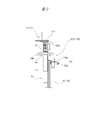
以下、本発明の逆打支柱位置決め冶具の実施形態の一例について図面を参照しながら詳細に説明する。本実施形態に係る逆打支柱位置決め冶具(以下、「位置決め冶具1」と略称する。)は、逆打工法において逆打支柱を位置決めするための冶具である。図1に示されるように、本実施形態に係る位置決め冶具1は、ケーシング10,支持部材20,プレート部材30及びガイド部材40を有する。
An example of an embodiment of a jig for positioning a reversed strut according to the present invention will be described in detail below with reference to the drawings. A reverse-strike support positioning jig (hereinafter abbreviated as "
<ケーシング>
図1に示されるように、位置決め冶具1が有するケーシング10は、長手方向両端(図1には上端のみが図示されている。)が開口した筒形に形成されている。ケーシング10は、地面Gに掘削された縦穴内に、その上端部10aが地面Gから突出するように設置される。図示されているケーシング10は、円筒形に形成されており、その全長は縦穴の深さよりも長い。もっとも、ケーシング10の形状は筒形であればよく、円筒形に限られない。また、ケーシング10は、その上端部10aが地面Gから突出するように縦穴内に設置可能な全長を備えていればよく、必ずしも縦穴の深さ以上の全長を備えている必要はない。さらに、ケーシング10を所望の位置を保持することができれば、ケーシング10の下端を縦穴の底に到達させる必要はない。つまり、縦穴の深さとの関係でケーシング10の全長を規定する必要はない。
<Casing>
As shown in FIG. 1, the
<支持部材>
図1に示されるように、位置決め冶具1は、2つの支持部材20(第1支持部材21及び第2支持部材22)を有する。第1支持部材21及び第2支持部材22は、実質的に同一の形状,構造及び寸法を備えている。第1支持部材21及び第2支持部材22は、所謂「H鋼」であって、一対のフランジ23a,23b及びウェブ24を有する。以下の説明では、各支持部材20におけるフランジ23aを「上側フランジ23a」と呼び、フランジ23bを「下側フランジ23b」と呼んで区別する場合がある。さらに、各支持部材20における上側フランジ23aの外面を当該支持部材20の「上面」と呼び、各支持部材20における下側フランジ23bの外面を当該支持部材20の「下面」と呼ぶ場合がある。もっとも、かかる区別や呼称は説明の便宜上の区別や呼称に過ぎない。
<Support member>
As shown in FIG. 1, the
第1支持部材21及び第2支持部材22は、ケーシング10の上端部10aの上方に、ケーシング10の上端開口部11を横断するように配置される。また、第1支持部材21及び第2支持部材22は、ウェブ24同士がケーシング10の径方向において対向する向きで互いに平行又は略平行に配置される。
The
<連結具>
図1に示されるように、第1支持部材21の長手方向における異なる二箇所は、一対の第1連結具51によってケーシング10の上端部10aにそれぞれ連結される。同じく、第2支持部材22の長手方向における異なる二箇所は、一対の第2連結具52によってケーシング10の上端部10aにそれぞれ連結される。より具体的には、第1支持部材21の長手方向中央よりも前方の一箇所が第1連結具51によって上端開口部11の縁に連結され、第1支持部材21の長手方向中央より後方の一箇所が他の第1連結具51によって上端開口部11の縁に連結される。
<connector>
As shown in FIG. 1, two different longitudinal positions of the
同様に、第2支持部材22の長手方向中央よりも前方の一箇所が第2連結具52によって上端開口部11の縁に連結され、第2支持部材22の長手方向中央よりも後方の一箇所が他の第2連結具52によって上端開口部11の縁に連結される。尚、図1では、作図の便宜上の理由から、第2支持部材22をケーシング10に連結する2つの第2連結具52のうちの一方のみが示されている。
Similarly, one point forward of the center in the longitudinal direction of the
第1連結具51及び第2連結具52は、同一の形状,構造及び寸法を有する。そこで、以下の説明では、第1連結具51及び第2連結具52を「連結具50」と総称する場合がある。
The
図2に示されるように、連結具50は、ケーシング10の上端開口部11の縁(ケーシング10の管壁)に固定される固定部53と、固定部53に連接された筒部54と、一端側が筒部54から上方に突出するように筒部54に挿入される支持部55と、を有する。そして、筒部54から突出している支持部55の一端が第1支持部材21又は第2支持部材22に連結される。
As shown in FIG. 2, the
固定部53は、アングル53a及びボルト53bから構成されている。アングル53aは、ケーシング10の上端開口部11の縁(ケーシング10の管壁)に引っ掛けることが可能な略L字形に形成されている。アングル53aの一端側は、ケーシング10の管壁の外側に配置され、管壁の外周面に沿って下方に延びている。一方、アングル53aの他端側は、ケーシング10の管壁の端面に載せられ、その端面は上端開口部11の内側に臨んでいる。そして、上端開口部11の内側に臨んでいるアングル53aの一方の端面に、筒部54が固定(溶接)されている。
The fixing
ケーシング10の管壁の外側に配置されるアングル53aの一端側には、これを貫通するねじ穴が設けられており、このねじ穴にボルト53bがねじ結合されている。ボルト53bは、ねじ穴を貫通して管壁の外周面に当接しており、ボルト53bを所定方向に回転させてねじ穴にねじ込むと、当該ボルト53bの先端面と筒部54の外周面との間に管壁が挟み込まれる。このようにして、アングル53a及びボルト53bから構成される固定部53がケーシング10の管壁の上端、つまりケーシング10の上端部10aに固定される。
A screw hole is provided through one end of the
支持部55は、筒部54に挿入可能な棒状に形成されており、その外周面には雄ねじが形成されている。支持部55にはカラー56が取り付けられており、カラー56の内周面には、支持部55の外周面に形成されている雄ねじとねじ結合する雌ねじが形成されている。支持部55の外周面に形成されている雄ねじとカラー56の内周面に形成されている雌ねじは、協働して送りねじとして機能する。また、カラー56の外周面には、当該カラー56の径方向外側に向けて延びる操作ピン56aが突設されている。操作ピン56aは、カラー56の径方向両側にそれぞれ突出している。
The
カラー56の下端面は筒部54の上端面に当接しており、カラー56を回転させると、筒部54に対する支持部55の挿入長が増減する。具体的には、操作ピン56aを把持してカラー56を第1方向に回転させると、送りねじの作用により、支持部55が筒部54に引き込まれ、筒部54に対する支持部55の挿入長が増加する。この結果、筒部54に対する支持部55の突出長が減少する。一方、操作ピン56aを把持してカラー56を第1方向と反対の第2方向に回転させると、送りねじの作用により、支持部55が筒部54から引き出され、筒部54に対する支持部55の挿入長が減少する。この結果、筒部54に対する支持部55の突出長が増加する。このように、筒部54に対する支持部55の突出長は変更可能である。以下、特に断らない限り、「支持部55の突出長」と言った場合、「筒部54に対する支持部55の突出長」を意味するものとする。
The lower end surface of the
それぞれの支持部55の上端には板状の当接部55aが設けられており、各当接部55aは、第1支持部材21又は第2支持部材22の下側フランジ23bに宛がわれている。より具体的には、第1連結具51の支持部55に設けられている当接部55aは、第1支持部材21の下側フランジ23bの外面、つまり第1支持部材21の下面に宛がわれている。また、第2連結具52の支持部55に設けられている当接部55aは、第2支持部材22の下側フランジ23bの外面、つまり第2支持部材22の下面に宛がわれている。それぞれの当接部55aと下側フランジ23bとは、クランプ57(図1)によって固定されている。
A plate-shaped
再び図1を参照する。上記のように、第1支持部材21は、その前後二箇所が2つの第1連結具51の支持部55によって下方から支持されている。また、第2支持部材22は、その前後二箇所が2つの第2連結具52の支持部55によって下方から支持されている。よって、それぞれの第1連結具51が備える支持部55の突出長を変更することにより、第1支持部材21の長手方向における異なる二箇所からケーシング10の上端までの鉛直距離をそれぞれ調節可能である。また、それぞれの第2連結具52が備える支持部55の突出長を変更することにより、第2支持部材22の長手方向における異なる二箇所からケーシング10の上端までの鉛直距離をそれぞれ調節可能である。そして、第1支持部材21の長手方向における異なる二箇所からケーシング10の上端までの鉛直距離をそれぞれ調節すれば、第1支持部材21の高さや傾きが調節される(変更される。)。また、第2支持部材22の長手方向における異なる二箇所からケーシング10の上端までの鉛直距離をそれぞれ調節すれば、第2支持部材22の高さや傾きが調節される(変更される。)。つまり、各連結具50における支持部55の突出長を調節することにより、第1支持部材21及び第2支持部材22をケーシング10の上端開口部11の上方において、任意の高さで水平に保持することができる。もちろん、第1支持部材21と第2支持部材22の一方または双方を任意の角度で傾けることもできる。
Refer to FIG. 1 again. As described above, the
<プレート部材>
図1に示されるように、プレート部材30は、第1支持部材21及び第2支持部材22の上に、これら第1支持部材21及び第2支持部材22に跨って配置される。プレート部材30は、一対の縦板31,32と、それら縦板31,32を挟んで対向する上板33及び下板34と、を有する。上板33及び下板34は、長方形又は略長方形であり、互いに同一の形状及び寸法を有する。上板33及び下板34の幅は、縦板31,32の対向間隔よりも広い。よって、上板33及び下板34の幅方向一側は、縦板31の外側に突出しており、上板33及び下板34の幅方向他側は、縦板32の外側に突出している。
<Plate member>
As shown in FIG. 1 , the
プレート部材30は、その下板34が第1支持部材21及び第2支持部材22の上面と対向する向きで第1支持部材21及び第2支持部材22の上に配置される。そして、縦板31,32の外側に突出している下板34の突出部分が、固定具としてのクランプ35によって第1支持部材21及び第2支持部材22の上側フランジ23aに固定される。もっとも、クランプ35による固定を解除すれば、プレート部材30を支持部材20の上で移動させることができる。具体的には、プレート部材30を支持部材20の長手方向と平行な方向及び長手方向と直交する方向の少なくとも2方向に移動させることができる。以下の説明では、支持部材20の長手方向と直交する方向を「X方向」、支持部材20の長手方向と平行な方向を「Y方向」と定義する。また、X方向及びY方向の双方と直交する方向を「Z方向」と定義する。
The
上記のように、プレート部材30は、支持部材20の上で、少なくともX方向及びY方向に移動可能であり、また、X方向及びY方向における任意の位置に移動させたプレート部材30は、クランプ35により当該位置に固定可能である。つまり、第1支持部材21及び第2支持部材22に対するプレート部材30の位置を調節可能である。
As described above, the
プレート部材30には、逆打支柱Aを挿入可能な矩形の開口部36が設けられている。プレート部材30が上板33及び下板を34有する本実施形態における開口部36は、上板33に設けられた上側開口部と、下板34に設けられた下側開口部と、を含む。尚、図示は省略されているが、プレート部材30の上板33の表面には、滑り止めのための凹凸が形成されている。
The
上板33の長手方向両側には、係止部としての吊りプレート37が複数設けられている。各吊りプレート37には、プレート部材30を含む当該位置決め冶具1の全部又は一部を吊り上げるための係止具(フック,ワイヤー,シャックル等)を係止可能な係止穴が形成されている。
A plurality of hanging
<ガイド部材>
図1に示されるガイド部材40は、プレート部材30に溶接されており、開口部36の周縁から逆打支柱Aの挿入方向(=Z方向)に沿って延在している。また、ガイド部材40は、開口部36に開口面に対して垂直に延在している。本実施形態では、2本のガイド部材40が開口部36の周縁からプレート部材30の下方に向かって延在している。
<Guide member>
The
それぞれのガイド部材40の全長は、逆打支柱Aの全長よりも短く、かつ、逆打支柱Aの全長の1/2よりも長い。本実施形態におけるガイド部材40の全長は、約6000mm(=約6m)である。また、それぞれのガイド部材40は、略コ字形の断面形状を有しており、互いに対向する向きで配置されている。この結果、開口部36を通過してケーシング10内(縦穴内)に降ろされる逆打支柱Aは、その全長の1/2以上が2つのガイド部材40によって四方から取り囲まれることになる。
The total length of each
ここで、逆打支柱Aとこれを取り囲むガイド部材40との間に数mmの隙間が生じるように、2つのガイド部材40の間隔が設定されている。位置決め精度の観点からは、かかる隙間は存在しないか、なるべく狭い方が好ましい。一方、隙間が全く存在しなかったり、隙間が狭すぎたりすると、逆打支柱Aとガイド部材40とが干渉し、逆打支柱Aの円滑な挿入が阻害される虞がある。そこで、本実施形態では、求められる位置決め精度を確保しつつ、逆打支柱Aの円滑な挿入を実現することを目的として、逆打支柱Aとこれを取り囲むガイド部材40との間に数mmの隙間が生じるように、対向するガイド部材40の間隔が設定されている。
Here, the distance between the two
<位置決め手順>
次に、主に図3~図6を参照しつつ、本実施形態に係る位置決め冶具1を用いて逆打支柱Aを位置決めする手順の一例について説明する。
<Positioning procedure>
Next, referring mainly to FIGS. 3 to 6, an example of a procedure for positioning the reverse-strike support A using the
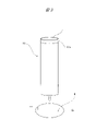
図3に示されるように、アースオーガー等を用いて掘削した縦穴H内にケーシング10を設置する。例えば、ケーシング10をクレーン等で吊り上げて縦穴H内に降ろす。ここで、ケーシング10の全長は縦穴Hの深さよりも長いので、ケーシング10の下端が縦穴Hの底に到達すると、ケーシング10の上端部10aが地面から突出する。例えば、ケーシング10の上部が地面Gから50cm程度突出する。言い換えれば、縦穴H内にケーシング10を設置したときに、地面Gから突出するケーシング10の一部が上端部10aである。
As shown in FIG. 3, the
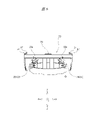
次に、図4に示されるように、ケーシング10の上端部10aの上方に支持部材20を配置する。具体的には、ケーシング10の管壁に、その周方向に沿って第1連結具51及び第2連結具52をそれぞれ固定し、それら第1連結具51及び第2連結具52が備える支持部55の上に支持部材20を搭載する。より具体的には、各連結具50の上端に設けられている当接部55a(図2)の上に各支持部材20の下側フランジ23bを載せ、当接部55aと下側フランジ23bとをクランプ57(図1)によって固定する。尚、図4では当接部55a及びクランプ57の図示を省略してある。
Next, as shown in FIG. 4, the
その後、各連結具50が備える支持部55の突出長を調節し、第1支持部材21及び第2支持部材22のZ方向における位置(高さ)及び傾きを調節する。通常、第1支持部材21及び第2支持部材22の高さは、基準面(通常は水平面)に対して同一の高さに調節される。また、第1支持部材21及び第2支持部材22の傾きは、基準面に対して平行に調節される。尚、支持部55の突出長の変更に伴って支持部材20の高さ及び傾きが変更される原理については既述のとおりである。
After that, the protruding length of the
次に、図5に示されるように、支持部材20の上にプレート部材30を載せる。例えば、プレート部材30をクレーン等で吊り上げ、支持部材20の上側フランジ23aの上に降ろす。プレート部材30をクレーン等で吊り上げる際には、プレート部材30に設けられている吊りプレート37を利用することができる。例えば、それぞれの吊りプレート37に設けられている係止穴に係止させたシャックルにワイヤーの一端に設けられている係止環を係止させ、当該ワイヤーの他端に設けられている係止環にクレーンのフックを引っ掛けてプレート部材30を吊り上げることができる。
Next, the
次に、支持部材20の上に載せられたプレート部材30を支持部材20の上でX方向やY方向に移動させて、プレート部材30を任意の位置に配置し、支持部材20に固定する。つまり、第1支持部材21及び第2支持部材22に対するプレート部材30の位置を任意の位置に合わせ、当該位置に固定する。
Next, the
ここまでの工程により、プレート部材30に設けられている開口部36の高さ,位置及び傾きが調節される。つまり、開口部36はプレート部材30に設けられており、そのプレート部材30は、Z方向における位置(高さ)及び傾きが予め調節された支持部材20の上に配置され、その後、X方向及びY方向の位置が調節される。よって、最終的には、開口部36の高さ,位置及び傾きが任意の高さ,位置及び傾きに調節される。
The height, position and inclination of the
もっとも、支持部材20及びプレート部材30を同時にケーシング10の上端部10aの上方に設置してもよい。つまり、第1支持部材21及び第2支持部材22に対するプレート部材30の位置合わせ及び固定を先行して行い、その後、プレート部材30が既に固定されている第1支持部材21及び第2支持部材22をケーシング10の上端部10aに固定してもよい。
However, the
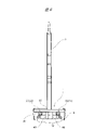
次に、図6に示されるように、逆打支柱Aをクレーン等で吊り上げる。例えば、逆打支柱Aの上端に係止させたワイヤーにクレーンのフックを引っ掛けて逆打支柱Aを吊り上げる。その後、吊り上げた逆打支柱Aをプレート部材30に設けられている開口部36に挿入し、ガイド部材40の内側を通し、当該ガイド部材40に沿ってケーシング10内に降ろす。ここで、開口部36のX方向及びY方向の位置やX-Y平面に対する高さ及び傾きは調節済である。また、ガイド部材40は、開口部36の開口面に対して垂直に延在している。よって、逆打支柱Aを開口部36に挿入し、開口部36に挿入された逆打支柱Aをガイド部材40の内側を通してケーシング10(縦穴H)内に降ろせば、当該逆打支柱Aの位置及び傾きは、調節済の開口部36の位置及び傾きと一致又は略一致する。つまり、逆打支柱Aの位置決めが行われる。さらに、ガイド部材40の全長は、逆打支柱Aの全長の1/2よりも長いので、挿入中の逆打支柱Aの揺れが防止又は抑制され、逆打支柱Aがより高精度に位置決めされる。
Next, as shown in FIG. 6, the upside-down strut A is lifted by a crane or the like. For example, a hook of a crane is hooked on a wire that is engaged with the upper end of the reverse strike strut A to lift the reverse strike strut A. After that, the lifted upside-down strut A is inserted into the
次に、縦穴Hの底部(ケーシング10の底部)にコンクリートを打設し、逆打支柱Aの下部を固定する。尚、逆打支柱Aの挿入前に縦穴Hの底部にコンクリートが打設されることもあることは既述のとおりである。その後、位置決め冶具1を撤去し、逆打支柱Aの埋め込み作業を完了する。例えば、ケーシング10と支持部材20との固定を解除し、支持部材20及びプレート部材30をまとめてクレーン等で吊り上げて撤去する。このとき、ケーシング10と支持部材20との固定は、クランプ57(図1)を取り外すだけで解除することができる。また、支持部材20とプレート部材30との固定も、クランプ35(図1)を取り外すだけで解除することができる。然る後、ジャッキ等を用いてケーシング10を縦穴Hから抜去する。
Next, concrete is placed in the bottom portion of the vertical hole H (bottom portion of the casing 10), and the lower portion of the reversed support A is fixed. As mentioned above, concrete may be placed at the bottom of the vertical hole H before the reverse-strike support A is inserted. After that, the
以上は、位置決め冶具1を用いて逆打支柱Aを位置決めする手順の一例であり、現場の状況等に応じて上記手順の一部を適宜することができる。例えば、上記手順では、連結具50の上に支持部材20を載せた後に支持部55の突出長を調節した。しかし、支持部55の突出長を調節した後に連結具50の上に支持部材20を載せてもよい。この場合、連結具50に載せられる支持部材20にプレート部材30が予め固定されていてもよい。かかる手順による場合には、連結具50の上で支持部材20をX方向やY方向に移動させることで、プレート部材30に設けられている開口部36及びガイド部材40の同方向の位置合わせが行われる。
The above is an example of the procedure for positioning the reverse-strike support A using the
また、ケーシング10以外の位置決め冶具1の構成要素(支持部材20,プレート部材30及びガイド部材40)を予め一体化し、かつ、支持部材20に連結具50を取り付けた上で、これらをケーシング10に固定してもよい。かかる手順による場合には、一体化された支持部材20,プレート部材30及びガイド部材40をケーシング10に固定した後、必要に応じて支持部55の突出長を調節したり、クランプ35を緩めてプレート部材30の位置を調節したりする。
In addition, the components of the
以上のように、本実施形態に係る位置決め冶具1は、簡易な構造でありながら、逆打支柱Aを必要十分な精度で位置決めすることができる。また、本実施形態に係る位置決め冶具1は、短時間で容易に組立て及び設置することができ、かつ、短時間で容易に解体及び撤去することもできる。
As described above, the
本発明は上記実施形態に限定されるものではなく、その要旨を逸脱しない範囲で種々変更可能である。 The present invention is not limited to the above embodiments, and can be modified in various ways without departing from the scope of the invention.
1…逆打支柱位置決め冶具(位置決め冶具)、10…ケーシング、10a…上端部、11…上端開口部、20…支持部材、21…第1支持部材、22…第2支持部材、23a…フランジ(上側フランジ)、23b…フランジ(下側フランジ)、24…ウェブ、30…プレート部材、31,32…縦板、33…上板、34…下板、35…クランプ、36…開口部、37…吊りプレート、40…ガイド部材、50…連結具、51…第1連結具、52…第2連結具、53…固定部、53a…アングル、53b…ボルト、54…筒部、55…支持部、55a…当接部、56…カラー、56a…操作ピン、57…クランプ、A…逆打支柱、G…地面
1... Reverse-strike support positioning jig (positioning jig), 10... Casing, 10a... Upper end, 11... Upper end opening, 20... Supporting member, 21... First supporting member, 22... Second supporting member, 23a... Flange ( Upper flange), 23b... Flange (lower flange), 24... Web, 30... Plate member, 31, 32... Vertical plate, 33... Upper plate, 34... Lower plate, 35... Clamp, 36... Opening, 37... Hanging
Claims (5)
長手方向両端が開口した筒形に形成され、前記逆打支柱が埋め込まれる縦穴内に設置されるケーシングと、
地面から突出している前記ケーシングの上端部にそれぞれ連結され、前記ケーシングの上端開口部を横断する第1支持部材及び第2支持部材と、
前記第1支持部材及び前記第2支持部材の上に、これら第1支持部材及び第2支持部材に跨って配置されるプレート部材と、
前記プレート部材に設けられ、前記逆打支柱を挿入可能な開口部と、
前記開口部の周縁から前記逆打支柱の挿入方向に沿って延在し、前記逆打支柱の挿入をガイドするガイド部材と、を有し、
前記第1支持部材の長手方向における異なる二箇所から前記ケーシングの上端までの鉛直距離をそれぞれ調節可能であり、
前記第2支持部材の長手方向における異なる二箇所から前記ケーシングの上端までの鉛直距離をそれぞれ調節可能であり、
前記第1支持部材及び前記第2支持部材に対する前記プレート部材の位置を調節可能であり、
前記ガイド部材の長さは、前記逆打支柱の全長よりも短く、かつ、前記逆打支柱の全長の1/2よりも長い、
逆打支柱位置決め冶具。 A jig for positioning a reverse-strike strut in a reverse-strike construction method,
a casing formed in a cylindrical shape with both longitudinal ends open and installed in a vertical hole in which the reverse-strike support is embedded;
a first support member and a second support member respectively connected to the upper end of the casing protruding from the ground and crossing the upper end opening of the casing;
a plate member disposed on the first support member and the second support member, straddling the first support member and the second support member;
an opening provided in the plate member into which the reverse-strike strut can be inserted;
a guide member extending from the peripheral edge of the opening along the direction of insertion of the reverse-strike strut and guiding insertion of the reverse-strike strut ;
vertical distances from two different locations in the longitudinal direction of the first support member to the upper end of the casing are adjustable,
Vertical distances from two different locations in the longitudinal direction of the second support member to the upper end of the casing are adjustable,
the position of the plate member relative to the first support member and the second support member is adjustable;
The length of the guide member is shorter than the total length of the reverse strut and longer than 1/2 of the total length of the reverse strut.
Reverse-strike support positioning jig.
2本の前記ガイド部材が前記開口部の周縁から前記逆打支柱の挿入方向に沿って延在しており、
前記開口部を通過した前記逆打支柱は、前記2本のガイド部材により四方から取り囲まれる、
逆打支柱位置決め冶具。 In the reverse-strike support positioning jig according to claim 1,
The two guide members extend from the periphery of the opening along the insertion direction of the reverse-strike strut,
The reverse strut that has passed through the opening is surrounded from all sides by the two guide members,
Reverse-strike support positioning jig.
前記第1支持部材の長手方向における異なる二箇所と前記ケーシングの前記上端部とをそれぞれ連結する一対の第1連結具と、
前記第2支持部材の長手方向における異なる二箇所と前記ケーシングの前記上端部とをそれぞれ連結する一対の第2連結具と、を有し、
前記第1連結具及び前記第2連結具のそれぞれは、
前記ケーシングの前記上端部に固定される固定部と、
前記固定部に連接された筒部と、
前記筒部に挿入されるとともに、当該筒部から突出している一端側が前記第1支持部材又は前記第2支持部材に連結される支持部と、を有し、
前記筒部に対する前記支持部の突出長を変更可能である、
逆打支柱位置決め冶具。 In the reverse-strike support positioning jig according to claim 1 or 2,
a pair of first connectors for respectively connecting two different locations in the longitudinal direction of the first support member and the upper end portion of the casing;
a pair of second connectors for respectively connecting two different locations in the longitudinal direction of the second support member and the upper end of the casing;
Each of the first connector and the second connector is
a fixing portion fixed to the upper end portion of the casing;
a cylindrical portion connected to the fixed portion;
a support part that is inserted into the tubular part and that is connected to the first supporting member or the second supporting member at one end protruding from the tubular part;
A protruding length of the support portion with respect to the cylindrical portion can be changed,
Reverse-strike support positioning jig.
前記プレート部材は、前記第1支持部材及び前記第2支持部材の長手方向と平行な方向に移動可能であり、かつ、前記第1支持部材及び前記第2支持部材の長手方向と直交する方向に移動可能であり、
任意の位置に移動された前記プレート部材は、複数の固定具により、前記第1支持部材及び前記第2支持部材に固定される、
逆打支柱位置決め冶具。 The reverse-strike support positioning jig according to any one of claims 1 to 3,
The plate member is movable in a direction parallel to the longitudinal directions of the first support member and the second support member, and in a direction orthogonal to the longitudinal direction of the first support member and the second support member. is movable and
The plate member moved to an arbitrary position is fixed to the first support member and the second support member by a plurality of fixtures,
Reverse-strike support positioning jig.
前記プレート部材に、当該逆打支柱位置決め冶具の全部又は一部を吊り上げるための係止具を係止可能な係止部が設けられている、
逆打支柱位置決め冶具。 The reverse-strike support positioning jig according to any one of claims 1 to 4,
The plate member is provided with a locking portion capable of locking a locking tool for lifting all or part of the reverse-strike support positioning jig,
Reverse-strike support positioning jig.
Priority Applications (1)
| Application Number | Priority Date | Filing Date | Title |
|---|---|---|---|
| JP2018228247A JP7181069B2 (en) | 2018-12-05 | 2018-12-05 | Reversed strut positioning jig |
Applications Claiming Priority (1)
| Application Number | Priority Date | Filing Date | Title |
|---|---|---|---|
| JP2018228247A JP7181069B2 (en) | 2018-12-05 | 2018-12-05 | Reversed strut positioning jig |
Publications (2)
| Publication Number | Publication Date |
|---|---|
| JP2020090839A JP2020090839A (en) | 2020-06-11 |
| JP7181069B2 true JP7181069B2 (en) | 2022-11-30 |
Family
ID=71013685
Family Applications (1)
| Application Number | Title | Priority Date | Filing Date |
|---|---|---|---|
| JP2018228247A Active JP7181069B2 (en) | 2018-12-05 | 2018-12-05 | Reversed strut positioning jig |
Country Status (1)
| Country | Link |
|---|---|
| JP (1) | JP7181069B2 (en) |
Families Citing this family (1)
| Publication number | Priority date | Publication date | Assignee | Title |
|---|---|---|---|---|
| CN117306832B (en) * | 2023-10-16 | 2026-04-07 | 宁波建工工程集团有限公司 | A type of disc-lock scaffolding |
Citations (4)
| Publication number | Priority date | Publication date | Assignee | Title |
|---|---|---|---|---|
| JP2000001854A (en) | 1998-06-15 | 2000-01-07 | Shimizu Corp | Pillar construction system and construction method |
| JP2002129562A (en) | 2000-10-26 | 2002-05-09 | Nishimatsu Constr Co Ltd | Construction method of trussed pillar |
| JP2006291550A (en) | 2005-04-11 | 2006-10-26 | Nippon Steel Corp | Column fixing member installation method and column fixing member installation device for steel pipe foundation pile |
| JP2015531442A (en) | 2012-10-11 | 2015-11-02 | アイエイチシー・アイキューアイピー・ユーケー・リミテッド | Pile driving guide |
Family Cites Families (2)
| Publication number | Priority date | Publication date | Assignee | Title |
|---|---|---|---|---|
| JPH0762658A (en) * | 1992-12-17 | 1995-03-07 | Shimizu Corp | Guide pipes used for installation of structure columns and installation method of structure columns using them |
| JP3631552B2 (en) * | 1996-01-26 | 2005-03-23 | 株式会社竹中工務店 | Upper centering device for guide pipe for construction of true pillar |
-
2018
- 2018-12-05 JP JP2018228247A patent/JP7181069B2/en active Active
Patent Citations (4)
| Publication number | Priority date | Publication date | Assignee | Title |
|---|---|---|---|---|
| JP2000001854A (en) | 1998-06-15 | 2000-01-07 | Shimizu Corp | Pillar construction system and construction method |
| JP2002129562A (en) | 2000-10-26 | 2002-05-09 | Nishimatsu Constr Co Ltd | Construction method of trussed pillar |
| JP2006291550A (en) | 2005-04-11 | 2006-10-26 | Nippon Steel Corp | Column fixing member installation method and column fixing member installation device for steel pipe foundation pile |
| JP2015531442A (en) | 2012-10-11 | 2015-11-02 | アイエイチシー・アイキューアイピー・ユーケー・リミテッド | Pile driving guide |
Also Published As
| Publication number | Publication date |
|---|---|
| JP2020090839A (en) | 2020-06-11 |
Similar Documents
| Publication | Publication Date | Title |
|---|---|---|
| JP4491030B2 (en) | Anchor bolt set device | |
| JP7059618B2 (en) | Main landing gear installation method and anchor frame installation jig | |
| JP6508958B2 (en) | Demolition system and demolition method | |
| JP6059176B2 (en) | Mobile lifting scaffold for assembling temporary elevated jetty | |
| JP7181069B2 (en) | Reversed strut positioning jig | |
| KR20190108739A (en) | Safety handrail for beam table form | |
| JP2019131990A (en) | Permanent sub-structural column erection method and permanent sub-structural column erection apparatus | |
| JPH0849235A (en) | Inclination adjusting device in construction method for building up permanent substractural column | |
| JP2008031650A (en) | Column and steel pipe pile positioning device and positioning method | |
| JP7554482B2 (en) | Fixing device for shoring and supporting pipes used therein | |
| KR20210078119A (en) | Supporter for installating horizontal member of supporting system | |
| JP7364105B2 (en) | Position adjustment device and method for adjusting the position of the structure pillar | |
| KR20210078117A (en) | Clamp for scaffold pipes | |
| JP6508959B2 (en) | Demolition system and demolition method | |
| CN113195836B (en) | Method and kit for making foundations for columns using plates embedded by vibration or percussion | |
| WO2024047878A1 (en) | Anchor bolt setting jig, and anchor bolt setting method | |
| KR101635931B1 (en) | Framework scaffold system with improved security and functionality | |
| JP5953856B2 (en) | Diagonal pile construction method | |
| KR102178790B1 (en) | Supporting structure for concrete wall | |
| JP6220140B2 (en) | Construction method of in-furnace scaffold and apparatus for constructing foundation deck of in-furnace scaffold | |
| JP2011247033A (en) | Attachment for single pipe and method of connecting single pipes for column using the same | |
| KR102680017B1 (en) | Strut structrue for temporary facilities | |
| JP7624038B2 (en) | Scaffolding base and temporary scaffolding assembly method | |
| JP2015048573A (en) | Ring-shaped wall positioning method using liner plate | |
| JP2015218576A (en) | Scaffold widening bracket and its mounting method |
Legal Events
| Date | Code | Title | Description |
|---|---|---|---|
| A621 | Written request for application examination |
Free format text: JAPANESE INTERMEDIATE CODE: A621 Effective date: 20210913 |
|
| A977 | Report on retrieval |
Free format text: JAPANESE INTERMEDIATE CODE: A971007 Effective date: 20220614 |
|
| A131 | Notification of reasons for refusal |
Free format text: JAPANESE INTERMEDIATE CODE: A131 Effective date: 20220621 |
|
| A521 | Request for written amendment filed |
Free format text: JAPANESE INTERMEDIATE CODE: A523 Effective date: 20220803 |
|
| TRDD | Decision of grant or rejection written | ||
| A01 | Written decision to grant a patent or to grant a registration (utility model) |
Free format text: JAPANESE INTERMEDIATE CODE: A01 Effective date: 20221115 |
|
| A61 | First payment of annual fees (during grant procedure) |
Free format text: JAPANESE INTERMEDIATE CODE: A61 Effective date: 20221117 |
|
| R150 | Certificate of patent or registration of utility model |
Ref document number: 7181069 Country of ref document: JP Free format text: JAPANESE INTERMEDIATE CODE: R150 |
|
| R250 | Receipt of annual fees |
Free format text: JAPANESE INTERMEDIATE CODE: R250 |
|
| S531 | Written request for registration of change of domicile |
Free format text: JAPANESE INTERMEDIATE CODE: R313531 |
|
| R350 | Written notification of registration of transfer |
Free format text: JAPANESE INTERMEDIATE CODE: R350 |