JP7178566B2 - Carrier tape processing device and carrier tape processing method - Google Patents

Carrier tape processing device and carrier tape processing method Download PDF

Info

Publication number
JP7178566B2
JP7178566B2 JP2021535617A JP2021535617A JP7178566B2 JP 7178566 B2 JP7178566 B2 JP 7178566B2 JP 2021535617 A JP2021535617 A JP 2021535617A JP 2021535617 A JP2021535617 A JP 2021535617A JP 7178566 B2 JP7178566 B2 JP 7178566B2
Authority
JP
Japan
Prior art keywords
carrier tape
roll body
case
unit
shaft member
Prior art date
Legal status (The legal status is an assumption and is not a legal conclusion. Google has not performed a legal analysis and makes no representation as to the accuracy of the status listed.)
Active
Application number
JP2021535617A
Other languages
Japanese (ja)
Other versions
JPWO2021192558A1 (en
Inventor
美伯 礒端
Current Assignee (The listed assignees may be inaccurate. Google has not performed a legal analysis and makes no representation or warranty as to the accuracy of the list.)
Panasonic Intellectual Property Management Co Ltd
Original Assignee
Panasonic Intellectual Property Management Co Ltd
Priority date (The priority date is an assumption and is not a legal conclusion. Google has not performed a legal analysis and makes no representation as to the accuracy of the date listed.)
Filing date
Publication date
Application filed by Panasonic Intellectual Property Management Co Ltd filed Critical Panasonic Intellectual Property Management Co Ltd
Publication of JPWO2021192558A1 publication Critical patent/JPWO2021192558A1/ja
Priority to JP2022112212A priority Critical patent/JP7349607B2/en
Application granted granted Critical
Publication of JP7178566B2 publication Critical patent/JP7178566B2/en
Active legal-status Critical Current
Anticipated expiration legal-status Critical

Links

Images

Classifications

    • BPERFORMING OPERATIONS; TRANSPORTING
    • B65CONVEYING; PACKING; STORING; HANDLING THIN OR FILAMENTARY MATERIAL
    • B65HHANDLING THIN OR FILAMENTARY MATERIAL, e.g. SHEETS, WEBS, CABLES
    • B65H35/00Delivering articles from cutting or line-perforating machines; Article or web delivery apparatus incorporating cutting or line-perforating devices, e.g. adhesive tape dispensers
    • B65H35/0006Article or web delivery apparatus incorporating cutting or line-perforating devices
    • B65H35/006Article or web delivery apparatus incorporating cutting or line-perforating devices with means for delivering a predetermined length of tape
    • B65H35/0066Article or web delivery apparatus incorporating cutting or line-perforating devices with means for delivering a predetermined length of tape this length being adjustable
    • HELECTRICITY
    • H05ELECTRIC TECHNIQUES NOT OTHERWISE PROVIDED FOR
    • H05KPRINTED CIRCUITS; CASINGS OR CONSTRUCTIONAL DETAILS OF ELECTRIC APPARATUS; MANUFACTURE OF ASSEMBLAGES OF ELECTRICAL COMPONENTS
    • H05K13/00Apparatus or processes specially adapted for manufacturing or adjusting assemblages of electric components
    • H05K13/04Mounting of components, e.g. of leadless components
    • H05K13/0417Feeding with belts or tapes
    • H05K13/0419Feeding with belts or tapes tape feeders
    • BPERFORMING OPERATIONS; TRANSPORTING
    • B65CONVEYING; PACKING; STORING; HANDLING THIN OR FILAMENTARY MATERIAL
    • B65HHANDLING THIN OR FILAMENTARY MATERIAL, e.g. SHEETS, WEBS, CABLES
    • B65H18/00Winding webs
    • B65H18/08Web-winding mechanisms
    • B65H18/10Mechanisms in which power is applied to web-roll spindle
    • BPERFORMING OPERATIONS; TRANSPORTING
    • B65CONVEYING; PACKING; STORING; HANDLING THIN OR FILAMENTARY MATERIAL
    • B65HHANDLING THIN OR FILAMENTARY MATERIAL, e.g. SHEETS, WEBS, CABLES
    • B65H75/00Storing webs, tapes, or filamentary material, e.g. on reels
    • B65H75/02Cores, formers, supports, or holders for coiled, wound, or folded material, e.g. reels, spindles, bobbins, cop tubes, cans, mandrels or chucks
    • B65H75/18Constructional details
    • B65H75/182Identification means
    • HELECTRICITY
    • H05ELECTRIC TECHNIQUES NOT OTHERWISE PROVIDED FOR
    • H05KPRINTED CIRCUITS; CASINGS OR CONSTRUCTIONAL DETAILS OF ELECTRIC APPARATUS; MANUFACTURE OF ASSEMBLAGES OF ELECTRICAL COMPONENTS
    • H05K13/00Apparatus or processes specially adapted for manufacturing or adjusting assemblages of electric components
    • H05K13/08Monitoring manufacture of assemblages
    • H05K13/086Supply management, e.g. supply of components or of substrates
    • BPERFORMING OPERATIONS; TRANSPORTING
    • B65CONVEYING; PACKING; STORING; HANDLING THIN OR FILAMENTARY MATERIAL
    • B65HHANDLING THIN OR FILAMENTARY MATERIAL, e.g. SHEETS, WEBS, CABLES
    • B65H2301/00Handling processes for sheets or webs
    • B65H2301/40Type of handling process
    • B65H2301/41Winding, unwinding
    • B65H2301/414Winding
    • B65H2301/4144Finishing winding process
    • B65H2301/41445Finishing winding process after winding process
    • B65H2301/41446Finishing winding process after winding process removing roll/core from shaft/mandrel, e.g. by compressed air
    • BPERFORMING OPERATIONS; TRANSPORTING
    • B65CONVEYING; PACKING; STORING; HANDLING THIN OR FILAMENTARY MATERIAL
    • B65HHANDLING THIN OR FILAMENTARY MATERIAL, e.g. SHEETS, WEBS, CABLES
    • B65H2701/00Handled material; Storage means
    • B65H2701/10Handled articles or webs
    • B65H2701/19Specific article or web
    • B65H2701/1942Web supporting regularly spaced non-adhesive articles

Landscapes

  • Engineering & Computer Science (AREA)
  • Manufacturing & Machinery (AREA)
  • Microelectronics & Electronic Packaging (AREA)
  • Operations Research (AREA)
  • Supply And Installment Of Electrical Components (AREA)
  • Replacement Of Web Rolls (AREA)

Description

本開示は、部品を収納したキャリアテープを処理するキャリアテープ処理装置およびキャリアテープ処理方法に関する。 The present disclosure relates to a carrier tape processing apparatus and a carrier tape processing method for processing a carrier tape containing components.

従来、基板に部品を搭載する部品実装装置における部品供給ユニットとして、部品を収納したキャリアテープを搬送することにより部品取出し位置に部品を供給するテープフィーダが知られている。テープフィーダにおいて使用されるキャリアテープはその保持体としてのリールに巻き付けられており、キャリアテープの運搬や保管および部品供給ユニットに対するセット等は、リールに巻き付けられた状態のまま(リール付きロール体のまま)行われる。 Conventionally, as a component supply unit in a component mounting apparatus for mounting components on a substrate, there is known a tape feeder that supplies components to a component pick-up position by conveying a carrier tape containing components. The carrier tape used in the tape feeder is wound around a reel as its holding body, and the carrier tape is transported, stored, set in the parts supply unit, etc. while being wound around the reel (roll body with reel). mama) is done.

このようなテープフィーダにおいて、リールは規格品であってその幅方向寸法を縮小化することは難しいことや、キャリアテープの使用が終了した後には空のリールが発生し、その処理や保管に手間がかかること等から、リールをなくし、キャリアテープをロール状に巻いたロール体の状態で部品供給ユニットに供給できるようにする装置が提案されている(例えば、下記の特許文献1)。特許文献1では、キャリアテープのロール体を部品の補充用の手段(部品補給手段)から部品供給ユニットの収納部に投入するようになっており、部品供給ユニットがキャリアテープを引き出し終わった後に不要なリールが実装作業現場に残らないようになっている。 In such a tape feeder, the reel is a standard product, and it is difficult to reduce the width dimension. For this reason, a device has been proposed in which the reel is eliminated and the carrier tape is wound into a roll and supplied to the component supply unit (for example, Patent Document 1 below). In Patent Document 1, a roll body of carrier tape is put into a storage section of a component supply unit from a component supply means (component supply means), and after the component supply unit finishes pulling out the carrier tape, it is unnecessary. It is designed not to leave a loose reel at the mounting work site.

特開平5-21990号公報JP-A-5-21990

そこで本開示は、安価な構成でリールなしの部品供給形態を実現できるキャリアテープ処理装置およびキャリアテープ処理方法を提供することを目的とする。 Therefore, an object of the present disclosure is to provide a carrier tape processing apparatus and a carrier tape processing method that can achieve a reel-less component supply form with an inexpensive configuration.

本開示のキャリアテープ処理装置は、部品を収納したキャリアテープを供給するキャリアテープ供給部と、前記キャリアテープを前記キャリアテープ供給部から引き出してロール状にしてケースに収納するキャリアテープ処理部と、を備え、前記キャリアテープ処理部は、前記キャリアテープの先端部を保持した軸部材を有し、前記軸部材を回転させることにより前記キャリアテープを前記軸部材に巻き付けてロール状のロール体を作成するロール体作成部と、前記ロール体作成部が作成した前記ロール体から前記軸部材を抜き取る軸部材抜き取り部と、を備え、前記軸部材は、キャリアテープの先端を挟み込んで保持するチャック部を有し、前記ロール体の厚み方向へ移動されることで前記ロール体から抜き取られるA carrier tape processing apparatus of the present disclosure includes a carrier tape supply unit that supplies a carrier tape containing components, a carrier tape processing unit that pulls out the carrier tape from the carrier tape supply unit, rolls the carrier tape, and stores it in a case. The carrier tape processing unit has a shaft member that holds the leading end of the carrier tape, and by rotating the shaft member, the carrier tape is wound around the shaft member to create a roll-shaped roll body. and a shaft member extracting portion for extracting the shaft member from the roll created by the roll body creating portion, wherein the shaft member has a chuck portion that sandwiches and holds the tip of the carrier tape. and is removed from the roll body by being moved in the thickness direction of the roll body .

本開示のキャリアテープ処理方法は、部品を収納したキャリアテープを供給するキャリアテープ供給部からキャリアテープを引き出すキャリアテープ引き出し工程と、前記キャリアテープ引き出し工程で引き出した前記キャリアテープをロール状にしてケースに収納するキャリアテープ処理工程と、を含み、前記キャリアテープ処理工程は、前記キャリアテープの先端部を保持した軸部材を回転させることにより前記キャリアテープを前記軸部材に巻き付けてロール状のロール体を作成するロール体作成工程と、前記ロール体から前記軸部材を抜き取って前記ロール体を前記ケースに収納するロール体収納工程と、を含み、前記軸部材は、キャリアテープの先端を挟み込んで保持するチャック部を有し、前記ロール体の厚み方向へ移動されることで前記ロール体から抜き取られるThe carrier tape processing method of the present disclosure includes a carrier tape pulling step of pulling out a carrier tape from a carrier tape supply unit that supplies a carrier tape containing components, and a case in which the carrier tape pulled out in the carrier tape pulling step is rolled into a case. and a carrier tape processing step for storing the carrier tape in a roll, wherein the carrier tape is wound around the shaft member by rotating the shaft member holding the tip portion of the carrier tape to form a roll-shaped roll body and a roll housing step of extracting the shaft member from the roll body and housing the roll body in the case, wherein the shaft member sandwiches and holds the tip of the carrier tape. It has a chuck portion that holds the roll body, and is extracted from the roll body by being moved in the thickness direction of the roll body .

本開示によれば、安価な構成でリールなしの部品供給形態を実現できる。 Advantageous Effects of Invention According to the present disclosure, it is possible to realize a reel-free component supply form with an inexpensive configuration.

図1は、本開示の一実施の形態における部品実装システムの概略構成図である。FIG. 1 is a schematic configuration diagram of a component mounting system according to one embodiment of the present disclosure. 図2は、本開示の一実施の形態における部品実装システムが備える部品実装装置の側面図である。FIG. 2 is a side view of a component mounting device included in the component mounting system according to the embodiment of the present disclosure; 図3は、本開示の一実施の形態における部品実装装置が使用するケース入りロール体の斜視図である。FIG. 3 is a perspective view of a cased roll used by the component mounting apparatus according to the embodiment of the present disclosure. 図4Aは、本開示の一実施の形態におけるキャリアテープ処理装置がケース入りロール体を製造する際に使用するケースの斜視図である。FIG. 4A is a perspective view of a case used when the carrier tape processing apparatus according to the embodiment of the present disclosure manufactures a cased roll body. 図4Bは、本開示の一実施の形態におけるキャリアテープ処理装置がケース入りロール体を製造する際に使用するケースの部分拡大図である。FIG. 4B is a partially enlarged view of a case used when the carrier tape processing apparatus according to the embodiment of the present disclosure manufactures the cased roll body. 図5Aは、本開示の一実施の形態におけるキャリアテープ処理装置が製造したケース入りロール体の斜視図である。FIG. 5A is a perspective view of a cased roll body manufactured by a carrier tape processing apparatus according to an embodiment of the present disclosure; 図5Bは、本開示の一実施の形態におけるキャリアテープ処理装置が製造したケース入りロール体の部分拡大図である。FIG. 5B is a partially enlarged view of the cased roll body manufactured by the carrier tape processing apparatus according to the embodiment of the present disclosure. 図6Aは、本開示の一実施の形態におけるキャリアテープ処理装置により製造したケース入りロール体の使用形態を示す図である。FIG. 6A is a diagram showing a usage pattern of a cased roll manufactured by a carrier tape processing apparatus according to an embodiment of the present disclosure. 図6Bは、本開示の一実施の形態におけるキャリアテープ処置装置により製造したケース入りロール体の使用形態を示す図である。FIG. 6B is a diagram showing a usage pattern of the cased roll manufactured by the carrier tape treatment apparatus according to the embodiment of the present disclosure. 図6Cは、本開示の一実施の形態におけるキャリアテープ処理装置により製造したケース入りロール体の使用形態を示す図である。FIG. 6C is a diagram showing a usage pattern of the cased roll manufactured by the carrier tape processing apparatus according to the embodiment of the present disclosure. 図7は、本開示の一実施の形態におけるキャリアテープ処理装置の側面図である。FIG. 7 is a side view of a carrier tape processing device according to an embodiment of the present disclosure; 図8は、本開示の一実施の形態におけるキャリアテープ処理装置の動作説明図である。FIG. 8 is an operation explanatory diagram of the carrier tape processing device according to the embodiment of the present disclosure. 図9は、本開示の一実施の形態におけるキャリアテープ処理装置の動作説明図である。FIG. 9 is an operation explanatory diagram of the carrier tape processing device according to the embodiment of the present disclosure. 図10は、本開示の一実施の形態におけるキャリアテープ処理装置の動作説明図である。FIG. 10 is an operation explanatory diagram of the carrier tape processing device according to the embodiment of the present disclosure. 図11は、本開示の一実施の形態におけるキャリアテープ処理装置の動作説明図である。FIG. 11 is an operation explanatory diagram of the carrier tape processing device according to the embodiment of the present disclosure. 図12は、本開示の一実施の形態におけるキャリアテープ処理装置の動作説明図である。FIG. 12 is an operation explanatory diagram of the carrier tape processing device according to the embodiment of the present disclosure. 図13は、本開示の一実施の形態におけるキャリアテープ処理装置の動作説明図である。FIG. 13 is an operation explanatory diagram of the carrier tape processing device according to the embodiment of the present disclosure. 図14Aは、本開示の一実施の形態におけるキャリアテープ処理装置の動作説明図である。FIG. 14A is an operation explanatory diagram of the carrier tape processing device according to the embodiment of the present disclosure. 図14Bは、本開示の一実施の形態におけるキャリアテープ処理装置の動作説明図である。FIG. 14B is an operation explanatory diagram of the carrier tape processing device according to the embodiment of the present disclosure. 図15は、本開示の一実施の形態におけるキャリアテープ処理装置の動作説明図である。FIG. 15 is an operation explanatory diagram of the carrier tape processing device according to the embodiment of the present disclosure. 図16は、本開示の一実施の形態における保管倉庫の斜視図である。FIG. 16 is a perspective view of a storage warehouse according to one embodiment of the present disclosure; 図17は、本開示の一実施の形態における部品実装システムの制御系統を示すブロック図である。FIG. 17 is a block diagram showing the control system of the component mounting system according to the embodiment of the present disclosure; 図18は、本開示の一実施の形態におけるキャリアテープ処理装置によりケース入りロール体を製造する作業の流れを示すフローチャートである。FIG. 18 is a flow chart showing the work flow of manufacturing the cased roll body by the carrier tape processing apparatus according to the embodiment of the present disclosure. 図19は、本開示の一実施の形態における保管倉庫によりケース入りロール体を保管する作業の流れを示すフローチャートである。FIG. 19 is a flow chart showing a work flow of storing cased roll bodies in a storage warehouse according to an embodiment of the present disclosure. 図20は、本開示の一実施の形態におけるケース入りロール体の運用のイメージを示す図である。FIG. 20 is a diagram showing an image of operation of a cased roll body according to an embodiment of the present disclosure.

本開示の実施の形態の説明に先立ち、従来の装置における問題点を簡単に説明する。 Prior to describing the embodiments of the present disclosure, problems in conventional devices will be briefly described.

特許文献1に記載の装置では、部品供給ユニットにキャリアテープのロール体を供給するための大掛かりな装置(部品補給手段)が必要であってコストがかかるという問題点がある。 The device described in Patent Document 1 has a problem that it requires a large-scale device (parts supplying means) for supplying the roll body of the carrier tape to the parts supplying unit, which is costly.

以下、図面を参照して本開示の実施の形態について説明する。図1は本開示の一実施の形態におけるキャリアテープ処理装置を含む部品実装システム1の構成図を示している。部品実装システム1は、製造ライン2と、製造ライン2に供給される部品の供給に関連するキャリアテープ処理装置3と、部品の保管と管理に関連する保管倉庫4を備えている。製造ライン2は、直列に連結された複数の装置の間でKBを受け渡ししながら作業を施すことによって基板KBに部品が装着された実装基板JKを製造する。 Embodiments of the present disclosure will be described below with reference to the drawings. FIG. 1 shows a configuration diagram of a component mounting system 1 including a carrier tape processing device according to one embodiment of the present disclosure. The component mounting system 1 includes a manufacturing line 2, a carrier tape processing device 3 related to the supply of components supplied to the manufacturing line 2, and a storage warehouse 4 related to storage and management of the components. The manufacturing line 2 manufactures a mounting board JK in which components are mounted on the board KB by carrying out operations while transferring the KB between a plurality of devices connected in series.

図1において、製造ライン2は情報管理端末5を通じて管理コンピュータ6に繋がっている。管理コンピュータ6は、製造ライン2を構成する各装置の動作の管理を行う。また、図1に示すように、キャリアテープ処理装置3と保管倉庫4も管理コンピュータ6と繋がっている。管理コンピュータ6は、キャリアテープ処理装置3と保管倉庫4の動作の管理も行う。図1に示すように、管理コンピュータ6には作業者用端末7が接続されており、部品実装システム1の作業者は作業者用端末7から部品実装システム1に対して種々の操作入力を行うことができるようになっている。 In FIG. 1, a production line 2 is connected to a management computer 6 through an information management terminal 5. FIG. The management computer 6 manages the operation of each device that constitutes the manufacturing line 2 . Further, as shown in FIG. 1, the carrier tape processing device 3 and the storage warehouse 4 are also connected to the management computer 6 . The management computer 6 also manages the operations of the carrier tape processing device 3 and the storage warehouse 4 . As shown in FIG. 1, a worker terminal 7 is connected to the management computer 6, and the worker of the component mounting system 1 performs various operational inputs to the component mounting system 1 from the worker terminal 7. It is possible to do so.

先ず、製造ライン2について説明する。図1において、製造ライン2は、基板供給装置11、印刷装置12、印刷後検査装置13、複数の部品実装装置14、実装後検査装置15、リフロー装置16、最終検査装置17および基板回収装置18を備えている。 First, the production line 2 will be explained. In FIG. 1, the production line 2 includes a substrate supply device 11, a printing device 12, a post-printing inspection device 13, a plurality of component mounting devices 14, a post-mounting inspection device 15, a reflow device 16, a final inspection device 17, and a substrate recovery device 18. It has

基板供給装置11は基板KBを下流側の印刷装置12に順次供給する。印刷装置12は基板供給装置11から供給される基板KBを搬入し、基板KBの表面に形成された電極にペースト状の半田を塗布して下流側の印刷後検査装置13に搬出する。印刷後検査装置13は印刷装置12から搬出された基板KBを搬入し、半田の塗布状態が不良な箇所がないかどうかをカメラで観察して検査したうえで、下流側の部品実装装置14に基板KBを搬出する。 The substrate supply device 11 sequentially supplies the substrates KB to the printing device 12 on the downstream side. The printing device 12 carries in the board KB supplied from the board supply device 11, applies solder paste to the electrodes formed on the surface of the board KB, and carries it out to the post-printing inspection device 13 on the downstream side. The post-printing inspection device 13 carries in the board KB carried out from the printing device 12, inspects it by observing with a camera whether or not there is any part where the solder coating state is poor, and then sends it to the component mounting device 14 on the downstream side. The substrate KB is unloaded.

各部品実装装置14は、上流側から搬入された基板KBに部品を装着して下流側に搬出する。最も下流側に位置する部品実装装置14はその下流側に位置する実装後検査装置15に基板KBを搬出する。部品実装装置14については後述する。 Each component mounting apparatus 14 mounts a component on the board KB brought in from the upstream side, and carries out the board KB to the downstream side. The component mounting device 14 located on the most downstream side carries out the board KB to the post-mounting inspection device 15 located on the downstream side. The component mounting device 14 will be described later.

実装後検査装置15は、最も下流側に位置する部品実装装置14から搬出された基板KBを搬入し、部品の装着状態が不良な箇所がないかどうかをカメラで観察して検査したうえで、下流側のリフロー装置16に基板KBを搬出する。リフロー装置16は実装後検査装置15から搬出された基板KBを搬入し、リフロー炉を通過させることによって半田を溶融・固化させて部品を電極に接合させる。最終検査装置17はリフロー装置16を通過した基板KBを搬入し、部品の電極への接合状態をカメラで観察して検査したうえで、下流側の基板回収装置18に搬出する。基板回収装置18は最終検査装置17から搬出された基板KBを受け取って回収する。 The post-mounting inspection device 15 carries in the board KB carried out from the component mounting device 14 positioned furthest downstream, and inspects it by observing with a camera whether or not there is a place where the mounting state of the components is defective. The substrate KB is unloaded to the reflow device 16 on the downstream side. The reflow device 16 carries in the board KB carried out from the post-mounting inspection device 15, and passes it through a reflow furnace to melt and solidify the solder and join the components to the electrodes. The final inspection device 17 carries in the board KB that has passed through the reflow device 16, inspects the joining state of the components to the electrodes by observing it with a camera, and then carries it out to the board recovery device 18 on the downstream side. The substrate recovery device 18 receives and recovers the substrate KB carried out from the final inspection device 17 .

次に、図2を用いて部品実装装置14について説明する。図2において、部品実装装置14の基台21上には基台カバー22が設けられており、基台21と基台カバー22との間の作業空間23には基板KBを水平方向に搬送する基板搬送路24が設けられている。 Next, the component mounting device 14 will be described with reference to FIG. In FIG. 2, a base cover 22 is provided on the base 21 of the component mounting apparatus 14, and the board KB is transported horizontally to the working space 23 between the base 21 and the base cover 22. A substrate transport path 24 is provided.

基台21上の基板搬送路24を挟んだ両側の位置にはフィーダ台車25が連結されている。各フィーダ台車25には複数の部品供給ユニット26が取り付けられている。ここでは部品供給ユニット26はテープフィーダであり、スプロケット26Sによってキャリアテープ27を搬送することにより、所定の部品供給位置に部品BHをひとつずつ供給する。 Feeder carts 25 are connected to positions on both sides of the substrate transport path 24 on the base 21 . A plurality of component supply units 26 are attached to each feeder carriage 25 . Here, the component supply unit 26 is a tape feeder, and supplies the components BH one by one to a predetermined component supply position by conveying the carrier tape 27 with the sprocket 26S.

図2において、作業空間23内には、ヘッド移動機構31によって水平面内方向に移動される装着ヘッド32が設けられている。装着ヘッド32には部品吸着ノズル33が下方に延びて設けられている。部品吸着ノズル33の下端には、部品供給ユニット26が供給する部品BHが吸着される。 In FIG. 2, a mounting head 32 that is moved in the horizontal direction by a head moving mechanism 31 is provided in the work space 23 . A component suction nozzle 33 is provided on the mounting head 32 so as to extend downward. A component BH supplied by the component supply unit 26 is sucked to the lower end of the component suction nozzle 33 .

各部品実装装置14は、基板搬送路24が上流側から基板KBを搬入して位置決めしたら、部品供給ユニット26により部品BHを供給させながら装着ヘッド32に装着ターンを繰り返し行わせる。装着ヘッド32はひとつの装着ターンにおいて、部品供給ユニット26が供給する部品BHを吸着してピックアップする動作と、基板KB上の定められた部品搭載位置に部品BHを装着する動作を、この順で行う。装着ヘッド32に装着ターンを繰り返し行わせて基板KBに装着させるべき部品BHを全て装着したら、基板搬送路24を作動させて、基板KBを下流側に搬出する。 Each component mounting device 14 causes the component supply unit 26 to supply components BH and causes the mounting head 32 to repeatedly perform mounting turns when the circuit board transport path 24 carries in the circuit board KB from the upstream side and positions the circuit board KB. In one mounting turn, the mounting head 32 performs, in this order, an operation of sucking and picking up the component BH supplied by the component supply unit 26 and an operation of mounting the component BH at a predetermined component mounting position on the board KB. conduct. When all the components BH to be mounted on the board KB are mounted by causing the mounting head 32 to repeat mounting turns, the board transport path 24 is operated to unload the board KB to the downstream side.

ここで、部品実装装置14が部品BHの供給に使用するキャリアテープ27は、本実施の形態では、ケース入りロール体41から繰り出されるようになっている。ここで「ケース入りロール体41」とは、キャリアテープ27をロール状にしたロール体27Rがケース42に収納されたものをいう(図3も参照)。ケース入りロール体41は、従来用いられているリール付きのロール体とは異なるものである。ここで「リール付きのロール体」とは、ロール体27Rがリールにより保持されたものをいう。 In this embodiment, the carrier tape 27 used by the component mounting apparatus 14 to supply the components BH is unwound from the cased roll body 41 . Here, the "cased roll body 41" means a roll body 27R in which the carrier tape 27 is rolled and housed in a case 42 (see also FIG. 3). The cased roll body 41 is different from the conventionally used roll body with a reel. Here, the "roll body with reel" refers to a roll body 27R held by a reel.

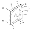
ここで、ケース入りロール体41のケース42について説明する。ケース42は、図4Aに示すように、左右の側壁51、底壁52、前壁53および後壁54を備えており、上方開口55と後開口56を有している。前壁53の外面には無線タグ42Mが貼り付けられている。後壁54の上部には、一方の側壁51の内面から内方へ張り出した上下の2つの突起ベース51Bが設けられており、2つの突起ベース51Bには、水平方向の外側に向かって突出したテープ先端保持部42Kが設けられている(図4B)。また、突起ベース51Bを設けた方の側壁51は、2つの突起ベース51Bに挟まれた部分が切り取られた切り欠き部42Dを備えている。ケース42の左右の側壁51には、上方開口55側の縁部からそれぞれの側壁51の中央部側に向かってU字形状に延びた溝部51Mが設けられている。 Here, the case 42 of the cased roll body 41 will be described. The case 42 includes left and right side walls 51, a bottom wall 52, a front wall 53 and a rear wall 54, and has an upper opening 55 and a rear opening 56, as shown in FIG. 4A. A wireless tag 42M is attached to the outer surface of the front wall 53 . Two upper and lower projection bases 51B projecting inward from the inner surface of one side wall 51 are provided on the upper part of the rear wall 54, and the two projection bases 51B project outward in the horizontal direction. A tape leading end holding portion 42K is provided (FIG. 4B). Moreover, the side wall 51 on which the projection bases 51B are provided has a notch portion 42D obtained by cutting a portion sandwiched between the two projection bases 51B. The left and right side walls 51 of the case 42 are provided with grooves 51M that extend in a U-shape from the edges on the upper opening 55 side toward the center side of each side wall 51 .

図5A、図5Bに示すように、ケース入りロール体41を保管中或いは運搬中であるときには、キャリアテープ27が有する送り孔27K(スプロケット26Sの外周歯と係合する孔)に、ケース42に設けられたテープ先端保持部42Kを差し込んで係止しておくようにする。なお、ケース入りロール体41を保管中或いは運搬中であるときとは、ケース42にロール体27Rを収納した場合であって、ロール体27Rからキャリアテープ27を引き出して使用する状況にないときを言う。本実施の形態では2つの送り孔27Kに、ケース42に設けられた2つのテープ先端保持部42Kを差し込んで係止する。これにより保管中或いは運搬中にケース入りロール体41のケース42からキャリアテープ27が抜け出ることが防止され、ひいてはロール体27Rの全体がケース42から脱落することが防止される。 As shown in FIGS. 5A and 5B, when the cased roll body 41 is being stored or transported, the feed hole 27K (the hole that engages with the outer peripheral teeth of the sprocket 26S) of the carrier tape 27 is inserted into the case 42. The provided tape leading end holding portion 42K is inserted and locked. Note that when the cased roll body 41 is being stored or transported means that the roll body 27R is stored in the case 42 and the carrier tape 27 is not pulled out from the roll body 27R for use. To tell. In this embodiment, two tape leading end holders 42K provided in the case 42 are inserted into and locked to the two feed holes 27K. This prevents the carrier tape 27 from slipping out of the case 42 of the cased roll body 41 during storage or transportation, and thus prevents the entire roll body 27R from dropping out of the case 42 .

一方、ケース入りロール体41からキャリアテープ27を引き出して使用する状況にあるときには、2つのテープ先端保持部42Kをキャリアテープ27の送り孔27Kから取り外し、更には図3に示すように前壁53が下面となるような姿勢にする。このように前壁53が下面となるような姿勢にしてキャリアテープ27を後開口56から引き出すことにより、キャリアテープ27を部品供給ユニット26に送ることが可能となる。このように、ケース42にテープ先端保持部42Kを設けることにより、ケース42におけるキャリアテープ27の先端部の位置が統一されるので、ケース42からキャリアテープ27の先端部を取り出す作業を容易に行うことができる。また、キャリアテープ27の先端部を取り出す作業をロボット等の自動化設備で行わせることにも容易に対応できる。 On the other hand, when the carrier tape 27 is pulled out from the cased roll body 41 and used, the two tape tip holding portions 42K are removed from the feed holes 27K of the carrier tape 27, and the front wall 53 is removed as shown in FIG. be positioned downward. By pulling out the carrier tape 27 from the rear opening 56 with the front wall 53 facing downward, the carrier tape 27 can be sent to the component supply unit 26 . Since the position of the leading end of the carrier tape 27 in the case 42 is unified by providing the tape leading end holding portion 42K in the case 42 in this manner, the operation of removing the leading end of the carrier tape 27 from the case 42 can be easily performed. be able to. Further, it is possible to easily cope with the operation of taking out the leading end of the carrier tape 27 by means of automated equipment such as a robot.

部品供給ユニット26に対するケース入りロール体41の使用形態としては、例えば、図2の左側に示すケース入りロール体41のように、フィーダ台車25に取り付ける形態のほか、図2の右側および図6Aに示すケース入りロール体41のように、アタッチメント26Aを介して部品供給ユニット26に取り付ける形態がある。或いは、図6Bに示すように、ケース入りロール体41の全体を部品供給ユニット26の内部に収納する形態もある。また或いは、図6Cに示すように、ケース入りロール体41からロール体27Rを取り出し、ロール体27Rのみを部品供給ユニット26の内部に収納する形態もある。 Examples of the usage of the cased roll body 41 for the component supply unit 26 include, for example, the cased roll body 41 shown on the left side of FIG. As in the cased roll body 41 shown, there is a form in which it is attached to the component supply unit 26 via an attachment 26A. Alternatively, as shown in FIG. 6B, there is also a form in which the entire cased roll body 41 is housed inside the component supply unit 26 . Alternatively, as shown in FIG. 6C, there is also a form in which the roll body 27R is taken out from the cased roll body 41 and only the roll body 27R is stored inside the component supply unit 26. FIG.

このように、本実施の形態において、ケース入りロール体41のケース42には、ロール体27Rを部品供給ユニット26の外部に設置して使用するときにおけるロール体27Rの支持手段の役割(従来のリール付きのロール体におけるリールの役割)を持たせることができる。 Thus, in the present embodiment, the case 42 of the cased roll body 41 serves as a means for supporting the roll body 27R when the roll body 27R is installed outside the parts supply unit 26 and used (conventional role of the reel in the roll body with the reel).

次に、キャリアテープ処理装置3について説明する。キャリアテープ処理装置3は、部品実装装置14で使用されるキャリアテープ27を処理してケース入りロール体41を製造する装置である。キャリアテープ処理装置3は、図7に示すように、部品BHを収納したキャリアテープ27を供給するキャリアテープ供給部61と、キャリアテープ27をキャリアテープ供給部61から引き出してロール状にしてケース42に収納するキャリアテープ処理部62と、ハンディスキャナ63および書き込み部64とを備えている。 Next, the carrier tape processing device 3 will be described. The carrier tape processing device 3 is a device that processes the carrier tape 27 used in the component mounting device 14 to manufacture the cased roll body 41 . As shown in FIG. 7, the carrier tape processing apparatus 3 includes a carrier tape supply unit 61 that supplies a carrier tape 27 containing components BH, and a case 42 that pulls out the carrier tape 27 from the carrier tape supply unit 61 and rolls the carrier tape 27 into a roll. , a carrier tape processing unit 62 for storing the tape, a handy scanner 63 and a writing unit 64 .

図7において、キャリアテープ供給部61は、部品BHを収納したキャリアテープ27が巻き付けられたリール61Rと、リール61Rを回転自在に支持したリール支持部61Sを備えている。リール61Rには、キャリアテープ27に収納された部品BHの情報(部品情報)が記録されたコードラベル61Lが貼り付けられている。コードラベル61Lは表面にバーコードや二次元コード等の識別子(シンボル)が印刷されている。リール61Rには、通常とは逆向きでキャリアテープ27を巻き取っている。8mm幅の紙テープのキャリアテープの場合、リール61Rから手前にキャリアテープ27を引き出すと左側に送り孔27Kが現れるが、部品供給ユニット26にキャリアテープ27を直接供給することが可能なリール(以下、通常のリールと呼ぶ)では右側に現れる。これは、後述するロール体作成部73で作成されたロール体27Rのキャリアテープ27の向きを通常のリールと同じ向きにするためである。 In FIG. 7, the carrier tape supply section 61 includes a reel 61R around which the carrier tape 27 containing the component BH is wound, and a reel support section 61S that rotatably supports the reel 61R. A code label 61L in which information (component information) of the component BH stored in the carrier tape 27 is recorded is attached to the reel 61R. The code label 61L has an identifier (symbol) such as a bar code or two-dimensional code printed on its surface. The carrier tape 27 is wound around the reel 61R in the opposite direction to the normal direction. In the case of a carrier tape made of paper tape with a width of 8 mm, when the carrier tape 27 is pulled forward from the reel 61R, a feeding hole 27K appears on the left side. (called normal reels) appear on the right side. This is to make the direction of the carrier tape 27 of the roll body 27R produced by the roll body production section 73, which will be described later, the same as that of a normal reel.

図7において、キャリアテープ処理部62は、ケース保持部71、キャリアテープ送り部72、ロール体作成部73、計測部74、クランパ75、カッタ76および軸部材抜き取り部77を備えている。 In FIG. 7 , the carrier tape processing section 62 includes a case holding section 71 , carrier tape feeding section 72 , roll forming section 73 , measuring section 74 , clamper 75 , cutter 76 and shaft member extracting section 77 .

ケース保持部71は、水平なケース搬送方向(図7の紙面に垂直な方向)に延びたコンベア機構から構成されている。ケース保持部71は複数のケース42それぞれを上方開口55が上を向くように一列に並べて状態に保持し、かつ、ケース搬送方向に向けて間欠的に搬送する。 The case holding portion 71 is composed of a conveyor mechanism extending in a horizontal case conveying direction (a direction perpendicular to the plane of FIG. 7). The case holding part 71 holds the plurality of cases 42 in a row so that the upper openings 55 face upward, and intermittently conveys them in the case conveying direction.

キャリアテープ送り部72は、キャリアテープ供給部61のリール61Rから繰り出されるキャリアテープ27を下方に(すなわちケース保持部71に保持されたケース42に)向けて送る送り動作をする。 The carrier tape feeder 72 feeds the carrier tape 27 unwound from the reel 61R of the carrier tape feeder 61 downward (that is, toward the case 42 held by the case holder 71).

図7において、ロール体作成部73は、軸部材81、軸部材移動部82、軸部材駆動部83を備えている。軸部材81は水平軸まわりに回転自在に設けられている。軸部材81にはチャック部81Aが設けられており、チャック部81Aにより、キャリアテープ27の先端部27Tを挟み込むことができるようになっている(図8→図9)。 In FIG. 7 , the roll forming section 73 includes a shaft member 81 , a shaft member moving section 82 and a shaft member driving section 83 . The shaft member 81 is provided rotatably around a horizontal axis. A chuck portion 81A is provided on the shaft member 81, and the tip portion 27T of the carrier tape 27 can be sandwiched by the chuck portion 81A (FIGS. 8 to 9).

軸部材移動部82は、キャリアテープ27の先端部27Tをチャック部81Aにより挟み込んだ軸部材81を、ケース42の上方の位置(図9)と、ケース42の溝部51M内の位置(「ケース内位置」と称する。図10)との間で移動させる機能を有する。軸部材駆動部83は、軸部材移動部82によって、軸部材81がケース内位置に移動された状態において、軸部材81を回転させる(図11中に示す矢印R)。これにより軸部材81のまわりにはキャリアテープ27が巻き付けられていく。 The shaft member moving portion 82 moves the shaft member 81, which sandwiches the tip portion 27T of the carrier tape 27 between the chuck portions 81A, between a position above the case 42 (FIG. 9) and a position within the groove portion 51M of the case 42 ("inside the case"). It has a function of moving between positions” (Fig. 10). The shaft member driving section 83 rotates the shaft member 81 in a state where the shaft member 81 is moved to the position inside the case by the shaft member moving section 82 (arrow R shown in FIG. 11). As a result, the carrier tape 27 is wound around the shaft member 81 .

このようにロール体作成部73は、キャリアテープ27の先端部27Tを保持する軸部材81を有し、軸部材81を回転させることによりキャリアテープ27を軸部材81に巻き付けてロール状のロール体27Rを作成する構成となっている。 As described above, the roll forming unit 73 has the shaft member 81 that holds the tip portion 27T of the carrier tape 27, and by rotating the shaft member 81, the carrier tape 27 is wound around the shaft member 81 to form the roll-shaped roll. 27R.

図7において、計測部74は、長さセンサ74Aと部品カウンタ74Bから構成されている。長さセンサ74Aは、キャリアテープ送り部72の動作量に基づいて、キャリアテープ送り部72がキャリアテープ供給部61から引き出したキャリアテープ27の長さを計測する。キャリアテープ送り部72はキャリアテープ27を繰り出すスプロケット72Aを備えており、長さセンサ74Aはスプロケット72Aの回転量をエンコーダ等で検出して引き出されたキャリアテープ27の長さを計測する。部品カウンタ74Bは、長さセンサ74Aの下方に位置しており、キャリアテープ供給部61から引き出された部品BHの数をカウントする。 In FIG. 7, the measuring section 74 is composed of a length sensor 74A and a parts counter 74B. The length sensor 74</b>A measures the length of the carrier tape 27 pulled out from the carrier tape supply section 61 by the carrier tape feeding section 72 based on the movement amount of the carrier tape feeding section 72 . The carrier tape feeding unit 72 has a sprocket 72A for feeding the carrier tape 27, and a length sensor 74A detects the amount of rotation of the sprocket 72A with an encoder or the like and measures the length of the carrier tape 27 pulled out. The parts counter 74B is positioned below the length sensor 74A and counts the number of parts BH pulled out from the carrier tape supply section 61 .

図7において、クランパ75は部品カウンタ74Bの下方に設けられている。クランパ75は、ベース部75a上に一対のクランプ部材75b,75cを備えている。一対のクランプ部材75b,75cは互いに近接するように移動することによって、一対のクランプ部材75b,75cの間に位置するキャリアテープ27をクランプする(図11→図12)。 In FIG. 7, the clamper 75 is provided below the parts counter 74B. The clamper 75 has a pair of clamp members 75b and 75c on a base portion 75a. The pair of clamping members 75b and 75c move closer to each other to clamp the carrier tape 27 located between the pair of clamping members 75b and 75c (FIGS. 11 to 12).

図7において、カッタ76は部品カウンタ74Bとクランパ75の間に設けられており、2つの切断部材76a,76bが刃面を対向させて配置されている。2つの切断部材76a,76bは互いに近接する方向に移動されることで、2つの切断部材76a,76bの間を下方に延び、かつ、クランパ75によってクランプされたキャリアテープ27を切断する(図12→図13)。 In FIG. 7, a cutter 76 is provided between a part counter 74B and a clamper 75, and two cutting members 76a and 76b are arranged with their blade surfaces facing each other. The two cutting members 76a, 76b are moved toward each other to cut the carrier tape 27 extending downward between the two cutting members 76a, 76b and clamped by the clamper 75 (FIG. 12). → Fig. 13).

クランパ75のベース部75aは(すなわちクランパ75の全体は)、カッタ76がキャリアテープ27を切断した後、2つのクランプ部材75b,75cによってキャリアテープ27の先端部27Tとは反対側の端部である切断端部27E(図14A)をクランプした状態のまま、クランパ移動部75K(図7)によって移動される。そして、クランプ部材75bがケース42に設けられた切り欠き部42Dへ進入することによって(図14A→図14B)、キャリアテープ27の切断端部27Eをケース42に設けられたテープ先端保持部42Kにセット(固定)する(図14B。図5Bも参照)。そして、クランパ75によるキャリアテープ27のクランプを解除したうえで、クランパ75のベース部75aをケース42から離れる方向へ水平に移動させて切り欠き部42Dからクランプ部材75bを引き抜き、その後、ベース部75aをケース42の上方に移動(退避)させる(図14B→図15)。これによりケース42内にはキャリアテープ27のロール体27Rが形成された状態となる。 After the cutter 76 cuts the carrier tape 27, the base portion 75a of the clamper 75 (that is, the entire clamper 75) is clamped by two clamping members 75b and 75c at the opposite end of the carrier tape 27 from the leading end portion 27T. It is moved by the clamper moving part 75K (FIG. 7) while a cut end 27E (FIG. 14A) is clamped. Then, the clamp member 75b enters the notch portion 42D provided in the case 42 (FIGS. 14A→14B), thereby moving the cut end portion 27E of the carrier tape 27 to the tape leading end holding portion 42K provided in the case 42. Set (fix) (Fig. 14B, see also Fig. 5B). Then, after releasing the clamping of the carrier tape 27 by the clamper 75, the base portion 75a of the clamper 75 is horizontally moved away from the case 42 to pull out the clamp member 75b from the notch portion 42D, and then the base portion 75a. is moved (retracted) above the case 42 (FIG. 14B→FIG. 15). As a result, a roll body 27</b>R of the carrier tape 27 is formed in the case 42 .

このように本実施の形態において、クランパ75およびクランパ移動部75Kは、カッタ76で切断されたキャリアテープ27の先端部27Tとは反対側の端部(切断端部27E)をケース42に設けたテープ先端保持部42Kにセットするキャリアテープ端セット部75Sとなっている。 As described above, in the present embodiment, the clamper 75 and the clamper moving portion 75K have the end portion (the cut end portion 27E) of the carrier tape 27 cut by the cutter 76 opposite to the leading end portion 27T provided in the case 42. A carrier tape end setting portion 75S is set in the tape end holding portion 42K.

軸部材抜き取り部77は、ロール体作成部73が作成したロール体27Rから軸部材81を抜き取る。軸部材抜き取り部77は、軸部材81を、作成したロール体27Rの厚み方向へ移動させる機構を備える。軸部材抜き取り部77が軸部材81をロール体27Rの厚み方向へ移動させると、ロール体27Rはケース42の側壁51によって移動が妨げられるので、軸部材81はロール体27Rから引き抜かれる。これによりロール体作成部73によって作成されたロール体27Rは、ケース42に収納された状態となる。 The shaft member extracting section 77 extracts the shaft member 81 from the roll body 27R created by the roll body creating section 73 . The shaft member extraction part 77 has a mechanism for moving the shaft member 81 in the thickness direction of the produced roll body 27R. When the shaft member extracting portion 77 moves the shaft member 81 in the thickness direction of the roll body 27R, the side wall 51 of the case 42 prevents the roll body 27R from moving, so the shaft member 81 is pulled out from the roll body 27R. As a result, the roll body 27R produced by the roll body production section 73 is housed in the case 42. As shown in FIG.

ハンディスキャナ63は、バーコード等の識別子を光学的に読み取る装置である。ハンディスキャナ63は作業者によって操作され、キャリアテープ供給部61のリール61Rに貼り付けられているコードラベル61Lの識別子から部品情報を読み取る。ここで「部品情報」とは、キャリアテープ供給部61のリール61Rに巻き付けられているキャリアテープ27に収納されている部品BHに関する情報であり、部品BHの種類、部品名、特性、製造年月日、製造者、使用期限、部品数及びこれらの情報にアクセスするためのアクセス情報(URL等)の少なくともひとつを含んでいればよい。 The handy scanner 63 is a device that optically reads identifiers such as barcodes. The handy scanner 63 is operated by an operator to read component information from the identifier of the code label 61L attached to the reel 61R of the carrier tape supply section 61. FIG. Here, the "component information" is information on the component BH stored in the carrier tape 27 wound around the reel 61R of the carrier tape supply section 61, and includes the type, component name, characteristics, date of manufacture of the component BH. At least one of the date, manufacturer, expiration date, number of parts, and access information (URL etc.) for accessing these information should be included.

このように本実施の形態において、ハンディスキャナ63は、キャリアテープ27に収納された部品に関する情報である部品情報を取得する部品情報取得部となっている。なお、リール61Rが部品情報を記憶した無線タグを有している場合、ハンディスキャナ63に替えて、無線タグに記録されている情報を非接触で読み取る機能を有する非接触リーダを部品情報取得部として使用してもよい。 As described above, in the present embodiment, the handy scanner 63 serves as a component information acquisition unit that acquires component information, which is information regarding components stored in the carrier tape 27 . If the reel 61R has a wireless tag storing component information, the handy scanner 63 is replaced by a non-contact reader having a function of reading information recorded on the wireless tag without contact. may be used as

書き込み部64は、ケース保持部71によって保持されているケース42の無線タグ42Mに情報を無線通信によって書き込む。書き込み部64が無線タグ42Mに書き込む情報は、ハンディスキャナ63を通じて取得した(読み取った)部品情報と、識別情報である。 The writing unit 64 writes information to the wireless tag 42M of the case 42 held by the case holding unit 71 by wireless communication. The information written by the writing unit 64 to the wireless tag 42M is the component information acquired (read) through the handy scanner 63 and the identification information.

ここで「識別情報」とは、部品実装システム1において使用される一のロール体27Rに収納されている部品BHを他のロール体27Rに収納されている部品BHと識別するために使用する情報である。識別情報は、例えば、部品実装システム1が設置される工場内において発行されるシリアル番号によって構成される。本実施の形態では、識別情報は、後述するように、キャリアテープ27のロール体27Rが生成された際に、管理コンピュータ6において生成(発行)される。また、識別情報はケース42を管理するための管理情報としても利用される。すなわち、識別情報は、ロール体27Rを識別する目的とケース42を識別する目的の両方で使用される。 Here, "identification information" is information used for distinguishing a component BH stored in one roll body 27R used in the component mounting system 1 from a component BH stored in another roll body 27R. is. The identification information is composed of, for example, a serial number issued within the factory where the component mounting system 1 is installed. In this embodiment, the identification information is generated (issued) by the management computer 6 when the roll body 27R of the carrier tape 27 is generated, as will be described later. The identification information is also used as management information for managing the case 42 . That is, the identification information is used for both the purpose of identifying the roll body 27R and the purpose of identifying the case 42. FIG.

次に、保管倉庫4について説明する。保管倉庫4は、ケース入りロール体41を保管する。ここでいうケース入りロール体41とは、キャリアテープ処理装置3によって製造されたばかりのケース入りロール体41だけでなく、部品実装装置14において使用されて途中で戻されたような使用途中のケース入りロール体41も含まれる。 Next, the storage warehouse 4 will be explained. The storage warehouse 4 stores the cased roll body 41 . The cased roll body 41 here means not only the cased roll body 41 just manufactured by the carrier tape processing apparatus 3, but also the cased roll body 41 in the middle of use such as being used in the component mounting apparatus 14 and returned halfway through. A roll body 41 is also included.

図16において、保管倉庫4は、筐体91内に複数の棚部92(保管部)を有している。筐体91の前面下方には、入口93が設けられており、筐体91の内部には、入口93を通じて筐体91の外部(作業者OPの手前側)への張り出し動作と筐体91の内部(作業者OPから見た奥側)への引き込み動作とを行う移動テーブル94が設けられている。移動テーブル94は、ケース入りロール体41が保管倉庫4に保管される際には作業者OPの手前側へ張り出され、移動テーブル94に載置されたケース入りロール体41を筐体91内に収容するときには奥側に引き込まれる。 In FIG. 16, the storage warehouse 4 has a plurality of shelf sections 92 (storage sections) within a housing 91 . An entrance 93 is provided at the lower front surface of the housing 91, and inside the housing 91, there is a projecting operation to the outside of the housing 91 (the front side of the operator OP) through the entrance 93 and the housing 91. A moving table 94 is provided for retracting into the inside (the far side as seen from the operator OP). The moving table 94 protrudes in front of the operator OP when the cased roll body 41 is stored in the storage warehouse 4 , and moves the cased roll body 41 placed on the moving table 94 into the housing 91 . When it is housed inside, it is pulled inward.

保管倉庫4が備える複数の棚部92のそれぞれには、ケース入りロール体41を保管(載置)するための複数の保管位置92Sが予め定められている。すなわち本実施の形態において、各棚部92は、ロール体27Rを収納したケース42(すなわちケース入りロール体41)を保管する保管位置92Sを複数備えた保管部となっている。 A plurality of storage positions 92S for storing (placing) the cased roll bodies 41 are predetermined in each of the plurality of shelf sections 92 provided in the storage warehouse 4 . That is, in the present embodiment, each shelf 92 serves as a storage section having a plurality of storage positions 92S for storing cases 42 (that is, cased roll bodies 41) containing roll bodies 27R.

図16において、筐体91内にはケース移送機構95が設けられている。ケース移送機構95は、上下方向(Z軸方向とする)に延びたZ軸テーブル96と、作業者OPから見た前後方向(Y軸方向とする)に延びてZ軸テーブル96によって上下方向に移動されるY軸テーブル97と、作業者OPから見た横方向(X軸方向とする)に延びてY軸テーブル97によって前後方向に移動されるX軸テーブル98と、X軸テーブル98によってX軸方向に移動される移送ヘッド99とを備えている。 In FIG. 16, a case transfer mechanism 95 is provided inside the housing 91 . The case transfer mechanism 95 includes a Z-axis table 96 extending in the vertical direction (Z-axis direction) and a Z-axis table 96 extending in the front-rear direction (Y-axis direction) as viewed from the operator OP. A Y-axis table 97 to be moved, an X-axis table 98 extending in the lateral direction (X-axis direction) viewed from the operator OP and moved in the front-rear direction by the Y-axis table 97, and a transfer head 99 which is axially displaced.

ケース移送機構95は、Z軸テーブル96によるY軸テーブル97のZ軸方向への移動動作と、Y軸テーブル97によるX軸テーブル98のY軸方向への移動と、X軸テーブル98による移送ヘッド99のX軸方向への移動とによって、移送ヘッド99を三次元的に移動させる。移送ヘッド99はX軸方向に並んだ2つのフィンガ99Fを備えている。 The case transfer mechanism 95 includes a Z-axis table 96 that moves a Y-axis table 97 in the Z-axis direction, a Y-axis table 97 that moves an X-axis table 98 in the Y-axis direction, and an X-axis table 98 that moves a transfer head. The transfer head 99 is moved three-dimensionally by the movement of 99 in the X-axis direction. The transfer head 99 has two fingers 99F aligned in the X-axis direction.

位相ヘッド99は、2つのフィンガ99FをX軸方向に互いに近接或いは離間させることができる。2つのフィンガ99Fの間にケース入りロール体41が位置した状態で2つのフィンガ99Fが閉じるように作動されると、ケース入りロール体41は2つのフィンガ99Fによって(すなわち移送ヘッド99によって)把持される。 The phase head 99 can move the two fingers 99F toward or away from each other in the X-axis direction. With the cased roll 41 positioned between the two fingers 99F, when the two fingers 99F are actuated to close, the cased roll 41 is gripped by the two fingers 99F (i.e., by the transfer head 99). be.

図16において、移送ヘッド99には、撮像視野を作業者OPから見た奥方向に向けた非接触リーダ100が設けられている。非接触リーダ100は、移送ヘッド99がケース入りロール体41を把持する位置において、ケース入りロール体41のケース42に設けられた無線タグ42Mと正対するようになっている。 In FIG. 16, the transfer head 99 is provided with a non-contact reader 100 whose imaging field of view is oriented in the depth direction as seen from the operator OP. The non-contact reader 100 faces the wireless tag 42M provided on the case 42 of the cased roll 41 at the position where the transfer head 99 grips the cased roll 41. As shown in FIG.

非接触リーダ100は、無線タグ42Mと正対した状態において、無線タグ42Mに書き込まれている情報(ロール体27Rに収納されている部品BHの部品情報と識別情報)を無線通信にて読み取る。本実施の形態において、非接触リーダ100は、記憶部としての無線タグ42Mに書き込まれた識別情報を読み取る識別情報読み取り手段として機能するようになっている。非接触リーダ100は、ケース入りロール体41の無線タグ42Mに書き込まれている情報を読み取ったら、その読み取った情報を管理コンピュータ6に記憶させる(後述)。 The non-contact reader 100 reads information written in the wireless tag 42M (component information and identification information of the components BH stored in the roll body 27R) by wireless communication while facing the wireless tag 42M. In this embodiment, the contactless reader 100 functions as identification information reading means for reading identification information written in the wireless tag 42M as a storage unit. When the non-contact reader 100 reads the information written in the wireless tag 42M of the cased roll body 41, the read information is stored in the management computer 6 (described later).

複数の棚部92のそれぞれに定められた各保管位置92Sにはユニークな住所が与えられている。本実施の形態では、保管位置92Sにケース入りロール体41を保管(載置)するときには、ケース入りロール体41のロール体27R(キャリアテープ27)に収納されている部品BHの情報(部品情報)と、ケース入りロール体41の識別情報とを関連付けた(いわゆる紐付けした)情報が管理コンピュータ6に記憶される。さらに、部品情報と、保管位置92Sの情報(保管位置情報)とを関連付けた情報が管理コンピュータ6に記憶される(後述)。これにより管理コンピュータ6は、保管倉庫4のどの保管位置92Sに、どの部品BHを収納したケース入りロール体41が保管されているかを把握することができる。 Each storage location 92S defined on each of the plurality of shelves 92 is given a unique address. In the present embodiment, when the cased roll body 41 is stored (placed) at the storage position 92S, information on the parts BH stored in the roll body 27R (carrier tape 27) of the cased roll body 41 (component information ) and the identification information of the cased roll body 41 (so-called linked information) is stored in the management computer 6 . Furthermore, information that associates the part information with the information of the storage location 92S (storage location information) is stored in the management computer 6 (described later). As a result, the management computer 6 can grasp which storage position 92S in the storage warehouse 4 stores the cased roll body 41 containing which part BH.

図17は部品実装システム1の全体における制御系統をブロック図により示したものである。図17に示すように、管理コンピュータ6は、生産情報管理部101、部品監視部102、作業指示部103および情報管理部104を備えている。生産情報管理部101は部品実装システム1における生産計画データを記憶している。部品監視部102は、製造ライン2における部品BHの残数等を監視する。部品監視部102は部品切れが予測される場合、その旨を作業指示部103に伝達する。 FIG. 17 is a block diagram showing the overall control system of the component mounting system 1. As shown in FIG. As shown in FIG. 17, the management computer 6 includes a production information management section 101, a parts monitoring section 102, a work instruction section 103 and an information management section 104. FIG. A production information management unit 101 stores production plan data in the component mounting system 1 . The parts monitoring unit 102 monitors the remaining number of parts BH in the production line 2 and the like. When parts shortage is predicted, the parts monitoring unit 102 notifies the operation instructing unit 103 of the fact.

作業指示部103は、生産情報管理部101に記憶されている生産計画データに基づく機種の切り替え時の作業指示を、製造ライン2と作業者OPに対して行うとともに、次の機種の生産で使用する部品BHの払い出し等の指示を、保管倉庫4に対して行う。また作業指示部103は、部品監視部102からの情報に基づく作業指示(具体的には、保管倉庫4に対する補充用部品の払い出しの指示と、作業者OPに対する部品補充作業の指示)等を行う。 The work instruction unit 103 gives work instructions to the production line 2 and the operator OP at the time of model switching based on the production plan data stored in the production information management unit 101, and the work instructions are used in the production of the next model. The storage warehouse 4 is instructed to take out the parts BH to be stored. The work instruction unit 103 also issues work instructions based on the information from the parts monitoring unit 102 (specifically, instructions for dispensing parts for replenishment to the storage warehouse 4 and instructions for parts replenishment work for the operator OP). .

情報管理部104は、第1の情報管理部104a、第2の情報管理部104b、識別情報生成部104cおよび保管位置情報生成部104dを備えている(図17)。第1の情報管理部104aは部品情報を管理し、第2の情報管理部104bは保管倉庫4内における部品BHの保管位置92Sの情報(保管位置情報)を管理する。具体的には、第1の情報管理部104aは、生成されたロール体27Rについての部品情報と識別情報とを関連付けた状態で記憶する。また、第2の情報管理部104bは、生成されたロール体27Rについての識別情報と保管位置92Sの情報(保管位置情報)とを関連付けた状態で記憶する。 The information management section 104 includes a first information management section 104a, a second information management section 104b, an identification information generation section 104c, and a storage location information generation section 104d (FIG. 17). The first information management unit 104a manages the parts information, and the second information management unit 104b manages the information (storage position information) of the storage position 92S of the parts BH in the storage warehouse 4. FIG. Specifically, the first information management unit 104a stores the component information and identification information of the generated roll body 27R in association with each other. Further, the second information management unit 104b stores the generated identification information of the roll body 27R and the information (storage position information) of the storage position 92S in association with each other.

識別情報生成部104cは、キャリアテープ処理装置3において、軸部材抜き取り部77がロール体27Rから軸部材81を抜き取ったとき等に、ロール体27Rについての識別情報を生成(発行)する。保管位置情報生成部104dは、ケース入りロール体41が保管倉庫4に保管される際に、ケース入りロール体41の保管位置92Sを特定して保管位置情報を生成する。 The identification information generation unit 104c generates (issues) identification information about the roll body 27R when the shaft member extraction unit 77 in the carrier tape processing device 3 extracts the shaft member 81 from the roll body 27R. When the cased roll body 41 is stored in the storage warehouse 4, the storage position information generation unit 104d identifies the storage position 92S of the cased roll body 41 and generates storage position information.

図17に示すように、キャリアテープ処理装置3は処理装置制御部3Cを備えている。処理装置制御部3Cはキャリアテープ処理装置3が備えるキャリアテープ処理部62(ケース保持部71、キャリアテープ送り部72、ロール体作成部73の軸部材移動部82と軸部材駆動部83、計測部74(長さセンサ74A、部品カウンタ74B)、クランパ75、クランパ移動部75K、カッタ76、軸部材抜き取り部77)、ハンディスキャナ63および書き込み部64の制御を行う。また図17に示すように、保管倉庫4は倉庫制御部4Cを備えている。倉庫制御部4Cは、保管倉庫4が備える移動テーブル94、ケース移送機構95および非接触リーダ100の制御を行う。 As shown in FIG. 17, the carrier tape processing device 3 includes a processing device control section 3C. The processing device control unit 3C controls the carrier tape processing unit 62 provided in the carrier tape processing device 3 (the case holding unit 71, the carrier tape feeding unit 72, the shaft member moving unit 82 and the shaft member driving unit 83 of the roll body forming unit 73, the measuring unit 74 (length sensor 74A, parts counter 74B), clamper 75, clamper moving section 75K, cutter 76, shaft member extraction section 77), handy scanner 63 and writing section 64 are controlled. Further, as shown in FIG. 17, the storage warehouse 4 includes a warehouse control section 4C. The warehouse control section 4C controls the moving table 94, the case transfer mechanism 95 and the non-contact reader 100 provided in the storage warehouse 4. FIG.

次に、図18に示すフローチャートに従って、キャリアテープ処理装置3によるケース入りロール体41の製造作業(キャリアテープ27の処理作業)の流れを説明する。先ず、キャリアテープ処理装置3の処理装置制御部3Cは、キャリアテープ供給部61のリール61Rに巻き付けられているキャリアテープ27の部品情報を取得する(ステップST1における部品情報取得工程)。ここでは、部品情報の取得は、作業者OPがハンディスキャナ63によって、キャリアテープ供給部61のリール61Rに貼り付けられたコードラベル61Lの識別子を読み取ることによって行うが(図7)、他の方法によってもよい。例えば、作業者OPが、処理装置制御部3Cに繋がる入力装置(図示せず)から、コードラベル61Lの内容に相当する入力を行うのであってもよい。 Next, the flow of the manufacturing work (processing work of the carrier tape 27) of the cased roll body 41 by the carrier tape processing apparatus 3 will be described according to the flowchart shown in FIG. First, the processing device control unit 3C of the carrier tape processing device 3 acquires component information of the carrier tape 27 wound around the reel 61R of the carrier tape supply unit 61 (component information acquiring step in step ST1). Here, the operator OP obtains the component information by reading the identifier of the code label 61L attached to the reel 61R of the carrier tape supply section 61 with the handy scanner 63 (FIG. 7). It is good by For example, the operator OP may input the contents of the code label 61L from an input device (not shown) connected to the processing device control section 3C.

ステップST1でキャリアテープ供給部61のリール61Rに巻き付けられているキャリアテープ27の部品情報を取得したら、処理装置制御部3Cは、ケース保持部71を作動させて、これからロール体27Rを収納させようとするケース42(空のケース42)を、リール61Rの下方の作業位置に位置決めする(ステップST2のケース位置決め工程)。そして、ケース42を作業位置に位置決めしたら、処理装置制御部3Cは、軸部材移動部82を作動させて、ケース保持部71によって保持されている空のケース42の(すなわち作業位置の)上方の所定位置に軸部材81を移動させる(ステップST3の軸部材上方移動工程。図8)。 After acquiring the component information of the carrier tape 27 wound around the reel 61R of the carrier tape supply section 61 in step ST1, the processing device control section 3C operates the case holding section 71 to store the roll body 27R. The case 42 (empty case 42) is positioned at the working position below the reel 61R (case positioning step of step ST2). Then, after positioning the case 42 at the working position, the processing device control section 3C operates the shaft member moving section 82 to move the empty case 42 held by the case holding section 71 above (that is, at the working position). The shaft member 81 is moved to a predetermined position (the shaft member upward movement step of step ST3; FIG. 8).

処理装置制御部3Cは、ステップST3で軸部材81をケース42の上方の所定位置に移動させたら、リール61Rを回転させてキャリアテープ27を下方に繰り出させながらキャリアテープ送り部72によってキャリアテープ27を下方に送り、キャリアテープ27の先端部27Tを軸部材81に保持させる(ステップST4のテープ保持工程)。このテープ保持工程は、図示しないロボット等によって、キャリアテープ27の先端部27Tを把持させたうえで、キャリアテープ27の先端部27Tを軸部材81とチャック部81Aの間に挿通させるようにする。そして、その後にチャック部81Aを作動させることで、軸部材81とチャック部81Aとの間にキャリアテープ27の先端部27Tが挟み込まれるようにする(図9→図10)。 After moving the shaft member 81 to a predetermined position above the case 42 in step ST3, the processing device control unit 3C causes the carrier tape feeding unit 72 to feed the carrier tape 27 downward while rotating the reel 61R. is sent downward to hold the leading end portion 27T of the carrier tape 27 on the shaft member 81 (tape holding step of step ST4). In this tape holding step, the leading end 27T of the carrier tape 27 is gripped by a robot or the like (not shown), and then the leading end 27T of the carrier tape 27 is inserted between the shaft member 81 and the chuck portion 81A. Then, by operating the chuck portion 81A thereafter, the leading end portion 27T of the carrier tape 27 is sandwiched between the shaft member 81 and the chuck portion 81A (FIGS. 9 to 10).

処理装置制御部3Cは、キャリアテープ27の先端部27Tを軸部材81に保持させたら、軸部材移動部82を作動させて、軸部材81をケース保持部71によって作業位置に位置決めされたケース42のケース内位置に位置するように移動させる(ステップST5の軸部材下方移動工程。図10)そして、処理装置制御部3Cは、軸部材81をケース内に位置に位置させたら、キャリアテープ送り部72によってキャリアテープ供給部61からキャリアテープ27を下方に引き出す一方で(ステップST6のキャリアテープ引き出し工程)、軸部材駆動部83により軸部材81を回転させることによって、キャリアテープ27を軸部材81に巻き付けてロール状のロール体27Rを作成する(ステップST7のロール体作成工程。図11)。 After holding the leading end 27T of the carrier tape 27 on the shaft member 81, the processing device control unit 3C operates the shaft member moving unit 82 to move the shaft member 81 to the working position by the case holding unit 71. (shaft member downward movement step of step ST5; FIG. 10). While the carrier tape 27 is drawn downward from the carrier tape supply section 61 by 72 (the carrier tape drawing process of step ST6), the shaft member 81 is rotated by the shaft member driving section 83, so that the carrier tape 27 is attached to the shaft member 81. A roll-shaped roll body 27R is formed by winding (step ST7 for forming a roll body; FIG. 11).

処理装置制御部3Cは、ステップST6のキャリアテープ引き出し工程とステップST7のロール体作成工程では、軸部材81を回転させて軸部材81にキャリアテープ27を巻き付け始めた後、計測部74を構成する長さセンサ74Aによって、キャリアテープ27が引き出された長さを計測する(或いは計測部74を構成する部品カウンタ74Bによって、引き出された部品BHの数を計測する)。そして、処理装置制御部3Cは、キャリアテープ供給部61から引き出されたキャリアテープ27の長さが予め定められた所定の長さに達した(或いは、キャリアテープ供給部61から引き出された部品BHの数が予め定められた所定の数に達した)場合に、軸部材81の回転を停止させるようにする。 In the carrier tape drawing step of step ST6 and the roll body forming step of step ST7, the processing device control unit 3C rotates the shaft member 81 to start winding the carrier tape 27 around the shaft member 81, and then configures the measurement unit 74. The length sensor 74A measures the length by which the carrier tape 27 is pulled out (or the part counter 74B constituting the measuring unit 74 measures the number of parts BH pulled out). Then, the processing device control unit 3C determines that the length of the carrier tape 27 pulled out from the carrier tape supply unit 61 reaches a predetermined length (or the component BH pulled out from the carrier tape supply unit 61 reaches a predetermined length). reaches a predetermined number), the rotation of the shaft member 81 is stopped.

処理装置制御部3Cは、ロール体27Rが作成されたら、クランパ75によってキャリアテープ27をクランプする(ステップST8のクランプ工程。図11→図12)。そして、カッタ76を作動させて、キャリアテープ27を切断する(ステップST9の切断工程。図12→図13)。 When the roll body 27R is produced, the processing device control section 3C clamps the carrier tape 27 with the clamper 75 (clamping process of step ST8, FIG. 11→FIG. 12). Then, the cutter 76 is operated to cut the carrier tape 27 (cutting process of step ST9, FIG. 12→FIG. 13).

このように本実施の形態において、キャリアテープ処理装置3の処理装置制御部3Cは、計測部74が予め指定されたキャリアテープ27の長さもしくは予め指定された部品BHの数を計測したら、切断部としてのカッタ76にキャリアテープ27の切断を実行させる切断制御部として機能するようになっている。なお、ここでは、処理装置制御部3Cは、長さセンサ74Aが予め指定されたキャリアテープ27の長さを計測したときにカッタ76にキャリアテープ27を切断させるようになっているが、部品カウンタ74Bが予め指定された部品の数を計測したときにカッタ76にキャリアテープ27を切断させるようになっていてもよい。 As described above, in the present embodiment, the processing device control unit 3C of the carrier tape processing device 3 cuts the carrier tape 27 when the measuring unit 74 measures the length of the carrier tape 27 specified in advance or the number of parts BH specified in advance. It functions as a cutting control section that causes the cutter 76 as a section to cut the carrier tape 27 . Here, the processor control unit 3C causes the cutter 76 to cut the carrier tape 27 when the length sensor 74A measures the length of the carrier tape 27 specified in advance. The cutter 76 may be configured to cut the carrier tape 27 when the number of parts designated in advance is counted by 74B.

処理装置制御部3Cは、カッタ76を作動させてキャリアテープ27を切断したら、クランパ移動部75Kを作動させ、前述の要領によって、カッタ76によって切断されたキャリアテープ27の切断端部27Eをケース42に設けられたテープ先端保持部42Kに固定する(ステップST10のテープ固定工程。図14A→図14B)。 After operating the cutter 76 to cut the carrier tape 27, the processing device control unit 3C operates the clamper moving unit 75K to move the cut end 27E of the carrier tape 27 cut by the cutter 76 to the case 42 according to the above-described procedure. (Tape fixing step of step ST10. FIG. 14A→FIG. 14B).

処理装置制御部3Cは、ステップST10でキャリアテープ27の切断端部27Eをケース42に固定したら、クランパ75のベース部75aを上方移動させたうえで(図15)、軸部材移動部82を作動させて、ケース42から(ロール体27Rから)軸部材81を引き抜く。これにより軸部材81にキャリアテープ27が巻き付けられることによって作成されたロール体27Rが、ケース42に収納される(ステップST11のロール体収納工程)。このロール体収納工程により、ひとつの空のケース42に1個のロール体27Rが収納されることになる。 After fixing the cut end portion 27E of the carrier tape 27 to the case 42 in step ST10, the processing device control unit 3C moves the base portion 75a of the clamper 75 upward (FIG. 15), and then operates the shaft member moving portion 82. and pull out the shaft member 81 from the case 42 (from the roll body 27R). As a result, the roll body 27R produced by winding the carrier tape 27 around the shaft member 81 is housed in the case 42 (roll body housing step of step ST11). Through this roll housing process, one roll 27R is housed in one empty case 42. As shown in FIG.

ここで、上記のロール体作成工程(ステップST7)からロール体収納工程(ステップST11)までの一連の工程は、キャリアテープ引き出し工程で引き出したキャリアテープ27をロール状にしてケース42に収納するキャリアテープ処理工程となっている。 Here, the series of steps from the roll forming step (step ST7) to the roll storing step (step ST11) is a carrier for storing the carrier tape 27 pulled out in the carrier tape pulling step into a roll shape and storing it in the case 42. It is a tape processing process.

処理装置制御部3Cは、ステップST11で軸部材81をケース42から抜き取るとき、管理コンピュータ6の識別情報生成部104cに、ケース42内のロール体27Rについての識別情報の生成を要請する。そして、処理装置制御部3Cから識別情報の生成を要請された識別情報生成部104cは、ケース42内のロール体27Rについての識別情報を生成する(ステップST12の識別情報生成工程)。 When the shaft member 81 is extracted from the case 42 in step ST11, the processing device control section 3C requests the identification information generation section 104c of the management computer 6 to generate identification information for the roll body 27R in the case 42. FIG. Then, the identification information generating section 104c requested to generate the identification information from the processing device control section 3C generates identification information about the roll body 27R in the case 42 (identification information generating step of step ST12).

ステップST12で識別情報生成部104cによって識別情報が生成されたら、処理装置制御部3Cは、その生成された識別情報を受け取る。そして、書き込み部64によって、ステップST1で取得した部品情報と、ステップST12で生成された識別情報を、ケース42(ロール体27Rが収納されているケース42)に取り付けられている無線タグ42Mに書き込む(ステップST13の書き込み工程)。 After the identification information is generated by the identification information generating section 104c in step ST12, the processing device control section 3C receives the generated identification information. Then, the writing unit 64 writes the component information acquired in step ST1 and the identification information generated in step ST12 to the wireless tag 42M attached to the case 42 (the case 42 containing the roll body 27R). (Write process of step ST13).

処理装置制御部3Cは、部品情報と識別情報をケース42の無線タグ42Mに書き込んだら、無線タグ42Mに書き込んだ情報(ロール体27Rについての部品情報および識別情報)を管理コンピュータ6に送信し、管理コンピュータ6の第1の情報管理部104aに、その情報(部品情報および識別情報)を記憶させる。これにより、ケース42内のロール体27Rについて、ロール体27Rの固有の情報である識別情報と、ロール体27Rに収納されている部品BHの情報である部品情報とが関連付けられた状態で管理コンピュータ6に登録される(ステップST14の部品情報登録工程)。 After writing the part information and the identification information to the wireless tag 42M of the case 42, the processing device control unit 3C transmits the information written to the wireless tag 42M (the part information and the identification information about the roll body 27R) to the management computer 6, The information (component information and identification information) is stored in the first information management section 104a of the management computer 6. FIG. As a result, with respect to the roll body 27R in the case 42, the identification information, which is the unique information of the roll body 27R, and the part information, which is the information of the parts BH stored in the roll body 27R, are associated with each other. 6 (component information registration step of step ST14).

処理装置制御部3Cは、ロール体27Rについての情報を管理コンピュータ6の第1の情報管理部104aに書き込んだら、製造しようとしているケース入りロール体41を全て製造したかどうかを判断する(ステップST15の終了判断工程)。そして、まだ全てのケース入りロール体41を製造していないと判断した場合にはステップST2に戻って新たにケース入りロール体41を製造し、全てのケース入りロール体41を製造したと判断した場合には、キャリアテープ処理装置3によるケース入りロール体41の製造(キャリアテープ27の処理作業)を終了する。 After writing the information about the roll 27R to the first information management section 104a of the management computer 6, the processing device control section 3C determines whether or not all the cased rolls 41 to be manufactured have been manufactured (step ST15). end judgment process). When it is determined that all the cased roll bodies 41 have not yet been manufactured, the process returns to step ST2 to newly manufacture the cased roll bodies 41, and it is determined that all the cased roll bodies 41 have been manufactured. In this case, the manufacture of the cased roll body 41 by the carrier tape processing device 3 (processing work of the carrier tape 27) is completed.

次に、図19に示すフローチャートを用いて、ケース入りロール体41の保管作業の流れを説明する。これには先ず、保管倉庫4の倉庫制御部4Cが、筐体91に設けられた入口93から移動テーブル94を手前側に移動させる。そして、作業者OPが(あるいは図示しない移動ロボットが)、移動テーブル94にケース入りロール体41を載置する(ステップST21の載置工程。図19)。このときケース入りロール体41は、上方開口55が上を向き、かつ、前壁53が手前側(作業者OPの側)を向く姿勢で移動テーブル94に載置される。これによりケース42に設けられた無線タグ42Mは、手前側を向いた状態となる(図16)。 Next, the flow of storage work for the cased roll body 41 will be described with reference to the flowchart shown in FIG. For this, first, the warehouse controller 4C of the storage warehouse 4 moves the moving table 94 from the entrance 93 provided in the housing 91 to the near side. Then, the operator OP (or a mobile robot (not shown)) places the roll body 41 in the case on the moving table 94 (step ST21, FIG. 19). At this time, the cased roll body 41 is placed on the moving table 94 in such a posture that the upper opening 55 faces upward and the front wall 53 faces the front side (the operator OP side). As a result, the wireless tag 42M provided on the case 42 faces forward (FIG. 16).

移動テーブル94にケース入りロール体41が載置されたら、倉庫制御部4Cは移動テーブル94を作動させて、ケース入りロール体41を筐体91内に引き込む。ケース入りロール体41が筐体91内に引き込まれたら、倉庫制御部4Cは移動テーブル94に載置されているケース入りロール体41の手前側に移送ヘッド99を移動させる。そして、2つのフィンガ99Fを閉じるように作動させて、移送ヘッド99にケース入りロール体41を把持させる。このとき移送ヘッド99に設けられた非接触リーダ100はケース入りロール体41のケース42に設けられた無線タグ42Mと正対し、非接触リーダ100は無線タグ42Mに書き込まれている識別情報を読み取る(ステップST22の識別情報読み取り工程)。 After the cased roll body 41 is placed on the moving table 94 , the warehouse control section 4</b>C operates the moving table 94 to pull the cased roll body 41 into the housing 91 . After the cased roll body 41 is drawn into the housing 91 , the warehouse control section 4</b>C moves the transfer head 99 to the front side of the cased roll body 41 placed on the moving table 94 . Then, the two fingers 99F are operated to close, and the transfer head 99 grips the cased roll body 41. As shown in FIG. At this time, the non-contact reader 100 provided on the transfer head 99 faces the wireless tag 42M provided on the case 42 of the cased roll body 41, and the non-contact reader 100 reads the identification information written on the wireless tag 42M. (Identification information reading step of step ST22).

非接触リーダ100が無線タグ42Mに書き込まれている識別情報を読み取ったら、倉庫制御部4Cは、非接触リーダ100が読み取った識別情報を管理コンピュータ6に送信する。そして、倉庫制御部4Cから識別情報の送信を受けた管理コンピュータ6は、保管位置情報生成部104dにおいて、その識別情報に対応するケース入りロール体41(非接触リーダ100が識別情報を読み取ったケース入りロール体41)の保管倉庫4内における保管位置92Sを特定して保管位置情報を生成する(ステップST23の保管位置情報生成工程)。保管位置92Sの特定は、その時点で空き状態となっている保管位置92Sの中から任意に或いは所定の規則に従って選択してなされる。 After the contactless reader 100 reads the identification information written in the wireless tag 42M, the warehouse control section 4C transmits the identification information read by the contactless reader 100 to the management computer 6. FIG. Then, the management computer 6, which has received the identification information from the warehouse control unit 4C, uses the storage position information generation unit 104d to store the roll body 41 in the case corresponding to the identification information. The storage position 92S of the incoming roll body 41) is specified in the storage warehouse 4 to generate storage position information (step ST23 for generating storage position information). The storage position 92S is specified by selecting it arbitrarily or according to a predetermined rule from among the storage positions 92S that are vacant at that time.

ステップST23で保管位置情報生成部104dが保管位置情報を生成したら、管理コンピュータ6は、その生成された保管位置情報と、その保管位置情報に対応するケース入りロール体41の識別情報とを関連付けた状態で、第2の情報管理部104bに記憶させる。これにより、保管倉庫4に保管されようとしているケース入りロール体41について、ロール体27Rの固有の情報である識別情報と、ロール体27Rを含むケース入りロール体41の保管倉庫4内での保管位置の情報(保管位置情報)とが関連付けられた状態で管理コンピュータ6に登録される(ステップST24の保管位置情報登録工程)。 When the storage position information generation unit 104d generates the storage position information in step ST23, the management computer 6 associates the generated storage position information with the identification information of the cased roll body 41 corresponding to the storage position information. state in the second information management unit 104b. As a result, for the roll body 41 in the case to be stored in the storage warehouse 4, the identification information, which is the unique information of the roll body 27R, and the storage of the roll body 41 in the case including the roll body 27R in the storage warehouse 4 Position information (storage position information) is registered in the management computer 6 in association with it (storage position information registration step of step ST24).

管理コンピュータ6は、移動テーブル94に載置されたケース入りロール体41についての保管情報と識別情報とを関連付けた状態で第2の情報管理部104bに記憶させる。そして、管理コンピュータ6は、ケース移送機構95を作動させて、移動テーブル94に載置されたケース入りロール体41を、保管位置情報に対応する保管位置92Sに移送して保管する(ステップST25の保管工程)。これによりケース入りロール体41の保管作業が終了する。 The management computer 6 causes the second information management section 104b to store storage information and identification information about the cased roll body 41 placed on the moving table 94 in association with each other. Then, the management computer 6 operates the case transfer mechanism 95 to transfer and store the cased roll body 41 placed on the moving table 94 to the storage position 92S corresponding to the storage position information (step ST25). storage process). As a result, the storage operation of the cased roll body 41 is completed.

このように、本実施の形態では、キャリアテープ供給部61のリール61Rから引き出したキャリアテープ27をロール状にしたロール体27Rをケース42に収納することで、ロール体27Rをケース入りロール体41として取り扱うことができるようになっている。ケース入りロール体41はリール付きのロール体よりも幅方向寸法を小さくしてコンパクト化を図ることができるうえ、ロール体27Rを(すなわちキャリアテープ27を)使い切った後にリールが廃棄物として残らないので作業性もよい。また、ケース42はそれ自体が安価であるだけでなく、リールと異なって再使用(使い回し)ができるので、その面でもコストを安価にすることができる。 As described above, in the present embodiment, the roll body 27R formed by rolling the carrier tape 27 pulled out from the reel 61R of the carrier tape supply section 61 is stored in the case 42, so that the roll body 27R is stored in the case-enclosed roll body 41. can be handled as The cased roll body 41 can be made compact by making the width dimension smaller than the roll body with the reel, and the reel does not remain as waste after the roll body 27R (that is, the carrier tape 27) is used up. Therefore, workability is also good. In addition, the case 42 itself is not only inexpensive, but can be reused (reused) unlike the reel, so the cost can be reduced in this respect as well.

更に、本実施の形態では、ケース42に部品情報を記憶させることができる記憶部としての無線タグ42Mが設けられており、リール61Rに巻き付けられているキャリアテープ27の部品情報を無線タグ42Mに書き込んで記憶させることができる。また、部品情報とロール体27Rの固有の情報である識別情報とを関連付けられて記憶されせることができるので、ケース入りロール体41ひとつひとつの単位で部品情報を管理することが可能である。 Furthermore, in the present embodiment, the case 42 is provided with a wireless tag 42M as a storage unit capable of storing component information. It can be written and stored. In addition, since the part information and the identification information, which is the unique information of the roll body 27R, can be associated and stored, the part information can be managed for each cased roll body 41 in units.

上述の部品実装システム1において、キャリアテープ処理装置3の処理装置制御部3C、キャリアテープ処理部62、部品情報読み取り部としてのハンディスキャナ63、書き込み部64、保管倉庫4(倉庫制御部4C、棚部92、ケース移送機構95、識別情報読み取り部としての非接触リーダ100)、情報管理部104(第1の情報管理部104a、第2の情報管理部104b、識別情報生成部104cおよび保管位置情報生成部104d)は部品管理装置110を構成している(図17)。 In the component mounting system 1 described above, the processing device control unit 3C of the carrier tape processing device 3, the carrier tape processing unit 62, the handy scanner 63 as a component information reading unit, the writing unit 64, the storage warehouse 4 (warehouse control unit 4C, shelf unit 92, case transfer mechanism 95, contactless reader 100 as an identification information reading unit), information management unit 104 (first information management unit 104a, second information management unit 104b, identification information generation unit 104c and storage position information The generation unit 104d) constitutes a parts management device 110 (FIG. 17).

部品管理装置110を用いた部品BHの管理作業(部品管理方法)は、先ず、部品情報を取得し(部品情報取得工程)、識別情報を生成したうえで(識別情報生成工程)、これら部品情報と識別情報をケース42に設けられた無線タグ42Mに書き込み(書き込み工程)、その書き込んだ部品情報と識別情報とを関連付けて第1の情報管理部104aに記憶させる(部品情報登録工程)。そして、無線タグ42Mに書き込んだ識別情報を識別情報読み取り部(非接触リーダ100)によって読み取り(識別情報読み取り工程)、保管位置92Sを特定して保管位置情報を生成したうえで(保管位置情報生成工程)、識別情報と保管位置情報とを関連付けて第2の情報管理部104bに記憶させる(保管位置情報登録工程)という手順で実行される。 The part BH management work (parts management method) using the parts management apparatus 110 first acquires part information (parts information acquisition process), generates identification information (identification information generation process), and then obtains the parts information. and identification information are written in the wireless tag 42M provided in the case 42 (writing step), and the written component information and the identification information are associated and stored in the first information management unit 104a (component information registration step). Then, the identification information written in the wireless tag 42M is read by the identification information reading unit (non-contact reader 100) (identification information reading step), and after specifying the storage location 92S and generating storage location information (storage location information generation step), and the identification information and storage location information are associated and stored in the second information management unit 104b (storage location information registration step).

このような部品管理方法によれば、ケース入りロール体41についての部品情報と識別情報が関連付けて記憶されるほか、ケース入りロール体41の識別情報と保管位置情報とが関連付けて記憶されるので、保管倉庫4におけるケース入りロール体41の保管および取り出しをスムーズに行うことができる。このため本実施の形態における部品管理装置110(部品管理方法)によれば、部品BHの入庫および出庫を簡単かつ効率よく行うことができる。 According to this parts management method, the part information and the identification information about the cased roll body 41 are associated and stored, and the identification information and storage position information of the cased roll body 41 are associated and stored. , storage and removal of the cased roll body 41 in the storage warehouse 4 can be performed smoothly. Therefore, according to the parts management apparatus 110 (parts management method) of the present embodiment, it is possible to easily and efficiently carry out the warehousing and delivery of the parts BH.

図20は、本実施の形態における部品実装システム1におけるケース入りロール体41の運用のイメージを図示したものである。この図に示すように、本実施の形態におけるケース入りロール体41は、キャリアテープ27が巻き付けられたリール61Rとケース42がキャリアテープ処理装置3に供給されることで製造される。キャリアテープ処理装置3で製造されたケース入りロール体41の一部は製造ライン2に送られて使用され、他の一部は保管倉庫4に保管(入庫)される。保管倉庫4に保管されたケース入りロール体41は、そこから出庫されて製造ライン2に送られ、使用される。そして、製造ライン2でケース入りロール体41のキャリアテープ27が使い切られることによって生じたケース42は回収されてキャリアテープ処理装置3に供給され、新たなケース入りロール体41の製造に再利用される。また、製造ライン2に送られたケース入りロール体41であって、キャリアテープ27がまだ使い切られていない状態のものの一部は、保管倉庫4に戻されて保管(入庫)される。 FIG. 20 illustrates an image of operation of the cased roll body 41 in the component mounting system 1 according to the present embodiment. As shown in this figure, cased roll body 41 in the present embodiment is manufactured by supplying reel 61R around which carrier tape 27 is wound and case 42 to carrier tape processing device 3 . A portion of the cased roll body 41 manufactured by the carrier tape processing apparatus 3 is sent to the manufacturing line 2 and used, and the other portion is stored (stored) in the storage warehouse 4 . The cased roll body 41 stored in the storage warehouse 4 is taken out from there and sent to the manufacturing line 2 for use. Then, the case 42 generated by the exhaustion of the carrier tape 27 of the case-in-roll body 41 in the production line 2 is collected and supplied to the carrier tape processing device 3, and reused for manufacturing a new case-in-roll body 41. be. Some of the cased roll bodies 41 sent to the production line 2, in which the carrier tape 27 has not yet been used up, are returned to the storage warehouse 4 and stored (stored).

以上説明したように、本実施の形態のおけるキャリアテープ処理装置3(キャリアテープ処理方法)では、キャリアテープ供給部61のリール61Rから引き出したキャリアテープ27をロール状にしたロール体27Rをケース42に収納することで、ロール体27Rをケース入りロール体41として取り扱うことができるようになっている。ケース入りロール体41はリール付きのロール体よりも幅方向寸法を小さくしてコンパクト化を図ることができるうえ、ロール体27Rを(すなわちキャリアテープ27を)使い切った後にリールが廃棄物として残らないので作業性もよい。 As described above, in the carrier tape processing apparatus 3 (carrier tape processing method) according to the present embodiment, the carrier tape 27 pulled out from the reel 61R of the carrier tape supply unit 61 is rolled and the roll body 27R is placed in the case 42. , the roll body 27R can be handled as a roll body 41 in a case. The cased roll body 41 can be made compact by making the width dimension smaller than the roll body with the reel, and the reel does not remain as waste after the roll body 27R (that is, the carrier tape 27) is used up. Therefore, workability is also good.

また、ケース42はそれ自体が安価であるだけでなく、リールと異なって再使用(使い回し)ができるので、その面でもコストを安価にすることができる。このため本実施の形態におけるキャリアテープ処理装置3(キャリアテープ処理方法)によれば、安価な構成でリールなしの部品供給形態を実現できる。 In addition, the case 42 itself is not only inexpensive, but can be reused (reused) unlike the reel, so the cost can be reduced in this respect as well. Therefore, according to the carrier tape processing apparatus 3 (carrier tape processing method) of the present embodiment, it is possible to realize a reel-less component supply mode with a low-cost configuration.

これまで本開示の実施の形態について説明してきたが、本開示は上述したものに限定されず、種々の変形等が可能である。例えば、上述の実施の形態において示したキャリアテープ処理部62の具体的構成は例示に過ぎず、キャリアテープ27をキャリアテープ供給部61から引き出してロール状にしてケース42に収納することができれば、その構成は自由である。また、リール61Rには、一般的に流通している通常のリールからキャリアテープ27を巻き取ったものを使用してもよい。この場合、ハンディスキャナ63はリール61Rからではなく、通常のリールの識別子から部品情報を読み取るようにする。 Although the embodiments of the present disclosure have been described so far, the present disclosure is not limited to the above, and various modifications and the like are possible. For example, the specific configuration of the carrier tape processing unit 62 shown in the above-described embodiment is merely an example. Its composition is free. Further, the reel 61R may be obtained by winding the carrier tape 27 from a generally distributed ordinary reel. In this case, the handy scanner 63 reads the component information not from the reel 61R but from an ordinary reel identifier.

安価な構成でリールなしの部品供給形態を実現できるキャリアテープ処理装置およびキャリアテープ処理方法を提供する。 To provide a carrier tape processing apparatus and a carrier tape processing method capable of realizing a component supply form without a reel with an inexpensive configuration.

3 キャリアテープ処理装置
3C 処理装置制御部(切断制御部)
27 キャリアテープ
27T 先端部
27E 切断端部(反対側の端部)
27R ロール体
41 ケース入りロール体
42 ケース
61 キャリアテープ供給部
62 キャリアテープ処理部
64 書き込み部
73 ロール体作成部
74 計測部
75S キャリアテープ端セット部
76 カッタ(切断部)
77 軸部材抜き取り部
81 軸部材
104 情報管理部
104a 第1の情報管理部
104b 第2の情報管理部
104c 識別情報生成部
BH 部品
3 carrier tape processing device 3C processing device control unit (cutting control unit)
27 carrier tape 27T tip 27E cut end (opposite end)
27R roll body 41 cased roll body 42 case 61 carrier tape supply unit 62 carrier tape processing unit 64 writing unit 73 roll body creation unit 74 measurement unit 75S carrier tape end setting unit 76 cutter (cutting unit)
77 Shaft member extraction unit 81 Shaft member 104 Information management unit 104a First information management unit 104b Second information management unit 104c Identification information generation unit BH Part

Claims (12)

部品を収納したキャリアテープを供給するキャリアテープ供給部と、
前記キャリアテープを前記キャリアテープ供給部から引き出してロール状にしてケースに収納するキャリアテープ処理部と、を備え、
前記キャリアテープ処理部は、
前記キャリアテープの先端部を保持した軸部材を有し、前記軸部材を回転させることにより前記キャリアテープを前記軸部材に巻き付けてロール状のロール体を作成するロール体作成部と、
前記ロール体作成部が作成した前記ロール体から前記軸部材を抜き取る軸部材抜き取り部と、を備え、
前記軸部材は、キャリアテープの先端を挟み込んで保持するチャック部を有し、前記ロール体の厚み方向へ移動されることで前記ロール体から抜き取られる、キャリアテープ処理装置。
a carrier tape supply unit that supplies a carrier tape containing components;
a carrier tape processing unit that pulls out the carrier tape from the carrier tape supply unit, rolls the carrier tape, and stores the carrier tape in a case;
The carrier tape processing unit is
a roll body forming unit having a shaft member holding a tip portion of the carrier tape, and winding the carrier tape around the shaft member by rotating the shaft member to form a roll-shaped roll body;
a shaft member extraction unit for extracting the shaft member from the roll body created by the roll body creation unit;
The carrier tape processing apparatus , wherein the shaft member has a chuck portion that sandwiches and holds the leading end of the carrier tape, and is extracted from the roll body by being moved in the thickness direction of the roll body .
前記ケースに設けた無線タグに前記キャリアテープに収納された部品に関する情報を書き込む書き込み部と、を備えた請求項1に記載のキャリアテープ処理装置。2. The carrier tape processing apparatus according to claim 1, further comprising a writing unit that writes information about components stored in the carrier tape to a wireless tag provided in the case. 前記キャリアテープ処理部は、前記キャリアテープ供給部から引き出されたキャリアテープを切断する切断部を備えた請求項1または2に記載のキャリアテープ処理装置。 The carrier tape processing apparatus according to claim 1 or 2, wherein the carrier tape processing section includes a cutting section that cuts the carrier tape pulled out from the carrier tape supply section. 前記キャリアテープ処理部は、
前記キャリアテープ供給部から引き出されたキャリアテープの長さもしくは前記キャリアテープ供給部から引き出された前記部品の数を計測する計測部と、
前記計測部が予め指定されたキャリアテープの長さもしくは予め指定された部品の数を計測したら前記切断部にキャリアテープの切断を実行させる切断制御部と、を有する請求項3に記載のキャリアテープ処理装置。
The carrier tape processing unit is
a measuring unit that measures the length of the carrier tape pulled out from the carrier tape supply unit or the number of the components pulled out from the carrier tape supply unit;
4. The carrier tape according to claim 3, further comprising a cutting control unit that causes the cutting unit to cut the carrier tape when the measuring unit measures a pre-specified length of the carrier tape or a pre-specified number of parts. processing equipment.
前記キャリアテープ処理部は、前記切断部で切断されたキャリアテープの前記先端部とは反対側の端部を前記ケースに設けたテープ先端保持部にセットするキャリアテープ端セット部を有する請求項4に記載のキャリアテープ処理装置。 5. The carrier tape processing section has a carrier tape end setting section for setting an end of the carrier tape cut by the cutting section opposite to the leading end of the carrier tape to a tape leading end holding section provided in the case. The carrier tape processing device according to 1. 空の前記ケースを保持するケース保持部を有し、前記ケース保持部が保持するひとつの前記空の前記ケースに1個の前記ロール体が収納される請求項1から5の何れかに記載のキャリアテープ処理装置。 6. The roll body according to any one of claims 1 to 5 , further comprising a case holding portion for holding the empty case, wherein one roll body is accommodated in one of the empty cases held by the case holding portion. Carrier tape processing equipment. 部品を収納したキャリアテープを供給するキャリアテープ供給部からキャリアテープを引き出すキャリアテープ引き出し工程と、
前記キャリアテープ引き出し工程で引き出した前記キャリアテープをロール状にしてケースに収納するキャリアテープ処理工程と、を含み、
前記キャリアテープ処理工程は、
前記キャリアテープの先端部を保持した軸部材を回転させることにより前記キャリアテープを前記軸部材に巻き付けてロール状のロール体を作成するロール体作成工程と、
前記ロール体から前記軸部材を抜き取って前記ロール体を前記ケースに収納するロール体収納工程と、を含み、
前記軸部材は、キャリアテープの先端を挟み込んで保持するチャック部を有し、前記ロール体の厚み方向へ移動されることで前記ロール体から抜き取られる、キャリアテープ処理方法。
a carrier tape drawing step of drawing out the carrier tape from a carrier tape supply unit that supplies the carrier tape containing the components;
A carrier tape processing step of rolling the carrier tape pulled out in the carrier tape pulling step and storing it in a case ,
The carrier tape processing step includes:
A roll body forming step of winding the carrier tape around the shaft member by rotating the shaft member holding the leading end of the carrier tape to form a roll body;
a roll body housing step of extracting the shaft member from the roll body and housing the roll body in the case,
The carrier tape processing method , wherein the shaft member has a chuck portion that sandwiches and holds the leading end of the carrier tape, and is removed from the roll body by being moved in the thickness direction of the roll body .
前記ケースに設けた無線タグに前記キャリアテープに収納された部品に関する情報を書き込む書き込み工程と、を含む請求項7に記載のキャリアテープ処理方法。8. The carrier tape processing method according to claim 7, further comprising a writing step of writing information about the parts stored in the carrier tape to a wireless tag provided in the case. 前記キャリアテープ処理工程は、前記キャリアテープ引き出し工程で引き出したキャリアテープを切断する切断工程を含む請求項7または8に記載のキャリアテープ処理方法。 The carrier tape processing method according to claim 7 or 8 , wherein the carrier tape processing step includes a cutting step of cutting the carrier tape drawn out in the carrier tape drawing step. 前記キャリアテープ処理工程は、
前記キャリアテープ引き出し工程で引き出したキャリアテープの長さもしくは前記キャリアテープ引工程で引き出した前記部品の数を計測する計測工程と、
前記計測工程で予め指定されたキャリアテープの長さもしくは予め指定された部品の数を計測したら前記切断工程を実行する請求項に記載のキャリアテープ処理方法。
The carrier tape processing step includes:
a measuring step of measuring the length of the carrier tape pulled out in the carrier tape pulling out step or the number of the parts pulled out in the carrier tape pulling out step;
10. The carrier tape processing method according to claim 9 , wherein the cutting step is performed after measuring the length of the carrier tape specified in advance or the number of parts specified in advance in the measuring step.
前記キャリアテープ処理工程は、前記切断工程で切断したキャリアテープの前記先端部とは反対側の端部を前記ケースに設けたテープ先端保持部にセットするキャリアテープ端セット工程を含む請求項10に記載のキャリアテープ処理方法。 11. The carrier tape processing step includes a carrier tape edge setting step of setting an edge of the carrier tape cut in the cutting step opposite to the edge of the carrier tape to a tape edge holder provided in the case. The described carrier tape processing method. 前記ロール体収納工程は、ひとつの空の前記ケースに1個の前記ロール体を収納する請求項7から11の何れかに記載のキャリアテープ処理方法。 12. The carrier tape processing method according to any one of claims 7 to 11, wherein in the roll housing step, one roll is housed in one empty case.
JP2021535617A 2020-03-25 2021-01-21 Carrier tape processing device and carrier tape processing method Active JP7178566B2 (en)

Priority Applications (1)

Application Number Priority Date Filing Date Title
JP2022112212A JP7349607B2 (en) 2020-03-25 2022-07-13 Carrier tape processing device and carrier tape processing method

Applications Claiming Priority (3)

Application Number Priority Date Filing Date Title
JP2020053535 2020-03-25
PCT/JP2021/001958 WO2021192558A1 (en) 2020-03-25 2021-01-21 Carrier-tape processing device and carrier-tape processing method

Related Child Applications (1)

Application Number Title Priority Date Filing Date
JP2022112212A Division JP7349607B2 (en) 2020-03-25 2022-07-13 Carrier tape processing device and carrier tape processing method

Publications (2)

Publication Number Publication Date
JPWO2021192558A1 JPWO2021192558A1 (en) 2021-09-30
JP7178566B2 true JP7178566B2 (en) 2022-11-28

Family

ID=77890109

Family Applications (2)

Application Number Title Priority Date Filing Date
JP2021535617A Active JP7178566B2 (en) 2020-03-25 2021-01-21 Carrier tape processing device and carrier tape processing method
JP2022112212A Active JP7349607B2 (en) 2020-03-25 2022-07-13 Carrier tape processing device and carrier tape processing method

Family Applications After (1)

Application Number Title Priority Date Filing Date
JP2022112212A Active JP7349607B2 (en) 2020-03-25 2022-07-13 Carrier tape processing device and carrier tape processing method

Country Status (5)

Country Link
US (1) US20230114831A1 (en)
JP (2) JP7178566B2 (en)
CN (1) CN115211249A (en)
DE (1) DE112021001830T5 (en)
WO (1) WO2021192558A1 (en)

Citations (3)

* Cited by examiner, † Cited by third party
Publication number Priority date Publication date Assignee Title
JP2005119880A (en) 2004-10-14 2005-05-12 Shin Etsu Polymer Co Ltd Tape winding device
JP2006114764A (en) 2004-10-15 2006-04-27 Murata Mfg Co Ltd Packaged electronic component and electronic component mounter
WO2020202737A1 (en) 2019-03-29 2020-10-08 パナソニックIpマネジメント株式会社 Carrier tape holding device, holder, and carrier tape package body

Family Cites Families (7)

* Cited by examiner, † Cited by third party
Publication number Priority date Publication date Assignee Title
JPS5845268Y2 (en) * 1976-11-30 1983-10-14 太陽誘電株式会社 electronic parts packaging box
JPS6228377A (en) * 1985-07-24 1987-02-06 株式会社村田製作所 Electronic part run container
JPH04173584A (en) * 1990-10-24 1992-06-22 Murata Mfg Co Ltd Package for chip-shaped electronic component
JPH0521990A (en) * 1991-07-17 1993-01-29 Matsushita Electric Ind Co Ltd Electronic part assembly and feeding apparatus for electronic part assembly
WO2006038385A1 (en) 2004-09-30 2006-04-13 Shibaura Mechatronics Corporation Adhesive film tape storing cassette replacing device, adhesive film tape storing cassette and adhesive film adhering device
JP2006290610A (en) 2005-04-15 2006-10-26 Brother Ind Ltd Tape roll for label, and cartridge for label
CN108128667A (en) 2016-12-01 2018-06-08 何政豪 Has the intelligent reel of radio frequency identification

Patent Citations (3)

* Cited by examiner, † Cited by third party
Publication number Priority date Publication date Assignee Title
JP2005119880A (en) 2004-10-14 2005-05-12 Shin Etsu Polymer Co Ltd Tape winding device
JP2006114764A (en) 2004-10-15 2006-04-27 Murata Mfg Co Ltd Packaged electronic component and electronic component mounter
WO2020202737A1 (en) 2019-03-29 2020-10-08 パナソニックIpマネジメント株式会社 Carrier tape holding device, holder, and carrier tape package body

Also Published As

Publication number Publication date
JP7349607B2 (en) 2023-09-25
DE112021001830T5 (en) 2023-01-05
US20230114831A1 (en) 2023-04-13
WO2021192558A1 (en) 2021-09-30
JPWO2021192558A1 (en) 2021-09-30
CN115211249A (en) 2022-10-18
JP2022140485A (en) 2022-09-26

Similar Documents

Publication Publication Date Title
JP6377752B2 (en) Component mounting system and component mounting method
WO2015037099A1 (en) Substrate work system, work method, and feeder transfer method
JP7113184B2 (en) Carrier tape processing device and carrier tape processing method
JP6676482B2 (en) Electronic component supply system
JP6684015B2 (en) Component mounting system and component mounting method
JP2022166081A (en) Work management system
JP6694767B2 (en) Splicing unit and electronic component supply system
WO2018185864A1 (en) Component mounting machine and system for managing component mounting line
JP7336645B2 (en) PARTS MANAGEMENT DEVICE AND PARTS MANAGEMENT METHOD
WO2021181759A1 (en) Holding device and component mounting system
JP7178566B2 (en) Carrier tape processing device and carrier tape processing method
WO2019229996A1 (en) Replacement system and replacement device
JP2021153153A (en) Carrier tape processing device and carrier tape processing method
JP7470907B2 (en) Component mounting system and method for processing carrier tape roll body
US20230114399A1 (en) Component mounting system and method for handling carrier tape roll body
JP2011003801A (en) Electronic circuit-assembling method and electronic circuit-assembling system
JP5473465B2 (en) Electronic component mounting equipment
JP2006332090A (en) Electronic component packaging equipment and method for managing component information in electronic component packaging equipment
JP7403045B2 (en) Carrier tape roll manufacturing device and carrier tape roll manufacturing method
WO2023139789A1 (en) Preparation device, mounting device, mounting system, and information processing method
JP2021153152A (en) Carrier tape roll body
JP7311704B2 (en) Filter exchange device and component mounting device
CN116605564A (en) Supply rack, production system, and supply method

Legal Events

Date Code Title Description
A621 Written request for application examination

Free format text: JAPANESE INTERMEDIATE CODE: A621

Effective date: 20210622

A871 Explanation of circumstances concerning accelerated examination

Free format text: JAPANESE INTERMEDIATE CODE: A871

Effective date: 20210908

A131 Notification of reasons for refusal

Free format text: JAPANESE INTERMEDIATE CODE: A131

Effective date: 20220105

A521 Request for written amendment filed

Free format text: JAPANESE INTERMEDIATE CODE: A523

Effective date: 20220218

A131 Notification of reasons for refusal

Free format text: JAPANESE INTERMEDIATE CODE: A131

Effective date: 20220524

A521 Request for written amendment filed

Free format text: JAPANESE INTERMEDIATE CODE: A523

Effective date: 20220713

TRDD Decision of grant or rejection written
A01 Written decision to grant a patent or to grant a registration (utility model)

Free format text: JAPANESE INTERMEDIATE CODE: A01

Effective date: 20221004

A61 First payment of annual fees (during grant procedure)

Free format text: JAPANESE INTERMEDIATE CODE: A61

Effective date: 20221017

R151 Written notification of patent or utility model registration

Ref document number: 7178566

Country of ref document: JP

Free format text: JAPANESE INTERMEDIATE CODE: R151