WO2019229996A1 - Replacement system and replacement device - Google Patents
Replacement system and replacement device Download PDFInfo
- Publication number
- WO2019229996A1 WO2019229996A1 PCT/JP2018/021270 JP2018021270W WO2019229996A1 WO 2019229996 A1 WO2019229996 A1 WO 2019229996A1 JP 2018021270 W JP2018021270 W JP 2018021270W WO 2019229996 A1 WO2019229996 A1 WO 2019229996A1
- Authority
- WO
- WIPO (PCT)
- Prior art keywords
- exchange
- replacement
- feeder
- detection unit
- detection
- Prior art date
Links
Images

Classifications
-
- H—ELECTRICITY
- H05—ELECTRIC TECHNIQUES NOT OTHERWISE PROVIDED FOR
- H05K—PRINTED CIRCUITS; CASINGS OR CONSTRUCTIONAL DETAILS OF ELECTRIC APPARATUS; MANUFACTURE OF ASSEMBLAGES OF ELECTRICAL COMPONENTS
- H05K13/00—Apparatus or processes specially adapted for manufacturing or adjusting assemblages of electric components
- H05K13/02—Feeding of components
- H05K13/021—Loading or unloading of containers
-
- H—ELECTRICITY
- H05—ELECTRIC TECHNIQUES NOT OTHERWISE PROVIDED FOR
- H05K—PRINTED CIRCUITS; CASINGS OR CONSTRUCTIONAL DETAILS OF ELECTRIC APPARATUS; MANUFACTURE OF ASSEMBLAGES OF ELECTRICAL COMPONENTS
- H05K13/00—Apparatus or processes specially adapted for manufacturing or adjusting assemblages of electric components
- H05K13/04—Mounting of components, e.g. of leadless components
- H05K13/0417—Feeding with belts or tapes
Definitions
- the present invention relates to an exchange system and an exchange device.
- Patent Document 1 discloses an exchange device as a replenishing device that automatically collects and replenishes feeders with a component mounting machine.
- Such an exchange device for example, can detect a feeder in an accommodation state by a detection sensor provided in the device main body, and is in a state where the feeder is accommodated in the device main body based on a detection result by the detection sensor, or is equipped in a component mounting machine Recognize whether it has been done.
- This specification aims to provide an exchange system and an exchange device that can determine the success or failure of the exchange process by more accurately grasping the state of the exchange element.
- the present specification includes an apparatus main body that accommodates an exchange element that is detachably mounted on a component mounting machine, and a holding unit that holds the exchange element and is movable in the attachment / detachment direction of the exchange element. , Based on a first detection unit and a second detection unit that detect the replacement element at detection positions different from each other in the attaching / detaching direction of the replacement element, a detection result of the first detection unit, and a detection result of the second detection unit, respectively. And a determination unit that determines whether or not the replacement process of the replacement element has been normally performed between the apparatus main body and the component mounting machine.
- the present specification includes an apparatus main body that accommodates an exchange element that is detachably mounted on a component mounting machine, and a holding unit that holds the exchange element and is movable in the attachment / detachment direction of the exchange element.
- a first detection unit provided in the apparatus main body for detecting the replacement element at a predetermined detection position in the attaching / detaching direction of the replacement element, and a second detection unit provided in the component mounting machine, wherein the replacement element
- the apparatus main body and the component mounting based on the detection result of the second detection unit that detects the exchange element at a detection position different from the first detection unit in the attaching / detaching direction, and the detection result of the first detection unit
- a determination unit that determines whether or not the exchange process of the exchange element has been normally performed with the machine.
- the replacement element is detected by the first detection unit and the second detection unit at detection positions having different attachment / detachment directions.
- the state of the exchange element by execution of exchange processing can be grasped more correctly. Therefore, the success or failure of the exchange process can be determined.
- FIG. 1 It is a perspective view which shows the production line to which the exchange system in embodiment is applied. It is a perspective view which shows the outline of a structure of the replacement
- An exchange system constituted by an exchange apparatus exchanges exchange elements with a component placement machine for at least one of various exchange elements installed in the component placement machine.
- the aspect by which the exchange system was applied to the production line comprised by the some component mounting machine is illustrated.
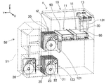
- the production line 1 is configured by installing a plurality of component mounting machines 10 side by side in the conveyance direction (X direction) of the substrate 90.
- a feeder storage device 5 used for storing the cassette-type feeder 20 is installed on the substrate carry-in side of the production line 1 (upper left side in FIG. 1).
- the production line 1 can include, for example, a screen printing machine, a mounting inspection machine, a reflow furnace, and the like.
- the production line 1 is applied with an exchange device 50 as a working device that performs a predetermined work on each of the plurality of component mounting machines 10 and the feeder storage device 5.
- Each device and the exchange device 50 constituting the production line 1 are configured to be able to input / output various data to / from the management device 6 via a network (not shown). The detailed configuration of the exchange device 50 will be described later.
- the feeder storage device 5 has a plurality of slots, and stocks the feeders 20 set in the slots.
- the feeder 20 is set in the feeder storage device 5
- communication between the feeder 20 and the management device 6 is possible.
- the slot of the feeder storage device 5 and the identification code (ID) of the feeder 20 set in the slot are associated with each other and recorded in the management device 6.
- the management device 6 monitors the operation status of the production line 1 and controls production facilities including the component mounting machine 10 and the feeder storage device 5.
- the management device 6 stores various data for controlling the component mounting machine 10.
- the management device 6 appropriately sends various data such as a control program to each production facility when executing production processing in each production facility.
- a plurality of component mounting machines 10 constituting the production line 1 includes a substrate transfer device 11, a component supply device 12, a head driving device 13, and a component camera. 14, a substrate camera 15, and a height sensor 16.
- the horizontal direction of the component mounting machine 10 is the X direction
- the horizontal depth direction of the component mounting machine 10 is the Y direction
- a vertical direction perpendicular to the X direction and the Y direction is the Z direction.
- the substrate transfer device 11 is constituted by a belt conveyor and a positioning device.
- the substrate transport apparatus 11 sequentially transports the substrates 90 in the transport direction and positions the substrate 90 at a predetermined position in the machine. After the mounting process by the component mounting machine 10 is completed, the board transfer device 11 carries the board 90 out of the component mounting machine 10.
- the component supply device 12 supplies components to be mounted on the substrate 90.
- the component supply device 12 has an upper slot 121 and a lower slot 122 in which the feeder 20 can be mounted.
- the upper slot 121 is disposed at the upper part on the front side of the component mounting machine 10 and holds the equipped feeder 20 in an operable manner.
- the feeder 20 installed in the upper slot 121 is controlled in operation in the mounting process by the component mounting machine 10, and supplies the component at the take-out portion provided at a predetermined position on the feeder 20.
- the lower slot 122 is arranged below the upper slot 121 and stocks the equipped feeder 20. That is, the lower slot 122 preliminarily holds the feeder 20 used for production, or temporarily holds the used feeder 20 used for production.
- the feeder 20 is exchanged between the upper slot 121 and the lower slot 122 by automatic exchange by an exchange device 50 described later or manual exchange by an operator.
- the head driving device 13 transfers the component supplied by the component supply device 12 to a predetermined mounting position on the substrate 90 carried into the apparatus by the substrate transfer device 11.
- the head drive device 13 moves the moving base 131 in the horizontal direction (X-axis direction and Y-axis direction) by the linear motion mechanism.
- the mounting head 30 is fixed to the movable table 131 in a replaceable manner by a clamp member (not shown).
- the mounting head 30 collects components and adjusts the vertical position and angle of the components to mount them on the substrate 90.
- the mounting head 30 is attached with a holding member that holds components supplied by the feeder 20.
- a holding member for example, a suction nozzle 31 that is supplied with a negative pressure to hold a component, a chuck that holds and holds the component, and the like can be applied.
- the mounting head 30 holds the holding member so as to be movable in the Z direction and rotatable about a ⁇ axis parallel to the Z axis.
- the mounting head 30 is moved in the XY directions by the linear motion mechanism of the head driving device 13.
- the component camera 14 and the substrate camera 15 are digital imaging devices having an imaging device such as a CMOS.
- the component camera 14 and the board camera 15 capture an image based on the control signal and send out image data acquired by the image capture.
- the component camera 14 is configured to be able to image a component held by the suction nozzle 31 of the mounting head 30 from below.
- the substrate camera 15 is configured to be able to image the substrate 90 from above.
- the height sensor 16 is provided on the movable table 131.
- the height sensor 16 measures the height from the object to the mounting head 30 by measuring the distance to the object located vertically below.
- the height sensor 16 for example, an optical sensor using laser light or the like can be adopted.
- the “object” may include, for example, the substrate 90 positioned by the substrate transport device 11, components mounted on the substrate 90, components supplied by the component supply device 12, and the like.
- the component mounting machine 10 configured as described above executes a mounting process for mounting a component on the substrate 90.
- the component mounting machine 10 sends a control signal to the head driving device 13 based on the result of image processing, the detection results of various sensors, a control program stored in advance, and the like. Thereby, the position and angle of the plurality of suction nozzles 31 supported by the mounting head 30 are controlled.
- the suction nozzle 31 held by the mounting head 30 is appropriately changed according to the type of component mounted on the substrate 90 in the mounting process.
- the component mounting machine 10 causes the mounting head 30 to hold the suction nozzle 31 accommodated in the nozzle station 35 when the suction nozzle 31 used in the mounting process to be executed is not held by the mounting head 30.
- the nozzle station 35 is detachably mounted at a predetermined position in the component mounting machine 10.
- Feeder 20 feeds and moves a carrier tape containing a large number of parts so that the parts can be collected.
- the case 21 of the feeder 20 is formed in a rectangular shape as a whole.
- the case 21 detachably holds a tape reel 23 around which the carrier tape 22 is wound.
- the carrier tape 22 stores components in a plurality of cavities formed at regular intervals in the feed direction.
- the feeder 20 when the feeder 20 is installed in the upper slot 121 or the lower slot 122 of the component supply device 12, electric power is supplied from the component mounting machine 10 via the connector. And the feeder 20 will be in the state which can communicate between the components mounting machines 10.
- FIG. The feeder 20 controls the feeding operation of the carrier tape 22 based on a control command from the component mounting machine 10. As a result, the feeder 20 supplies the components so as to be collected by the holding member of the mounting head 30 at the take-out portion provided at a predetermined position on the upper portion of the feeder 20.
- the exchange system 40 includes a first rail 41, a second rail 42, and an exchange device 50, as shown in FIGS.
- the first rail 41 is provided at the front of the plurality of component mounting machines 10. More specifically, the first rail 41 is provided between the upper slot 121 and the lower slot 122 in each of the plurality of component mounting machines 10.
- the second rail 42 is provided below the lower slot 122 of the component mounting machine 10.
- the first rail 41 and the second rail 42 having the above-described configuration extend over almost the entire region in the transport direction of the substrate 90 in the production line 1.
- the exchange device 50 is configured to be positioned at an arbitrary position in the X direction including the front side of the plurality of component mounting machines 10 and the feeder storage device 5 by the operation of the moving device 53 described later.
- the exchange device 50 is connected to a plurality of component placement machines 10 constituting the production line 1 and to the feeder storage device 5 by using the feeder 20 that supplies the components to be mounted on the substrate 90 as a replacement element.
- the feeder 20 is exchanged between them.
- the exchange process includes at least one of collecting and replenishing the feeder 20.
- the exchange device 50 conveys the feeder 20 from the feeder storage device 5 to the upper slot 121 or the lower slot 122 of the component mounting machine 10. Further, the exchange device 50 exchanges the feeder 20 between the upper slot 121 and the lower slot 122 of the component mounting machine 10. Further, the exchange device 50 conveys the used feeder 20 from the component mounting machine 10 to the feeder storage device 5.
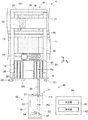
- the exchange device 50 includes a device main body 51, a holding unit 52, a moving device 53, a standard sensor 54, and a control device 60.
- the apparatus main body 51 holds the feeder 20 and holds the holding unit 52. Further, the apparatus main body 51 is provided with a drive device (not shown) for operating the holding unit 52.
- the holding unit 52 holds the feeder 20.
- the holding part 52 holds the feeder 20 as a structure for holding the case 21 of the feeder 20, a structure for locking with a locking part provided in the case 21, and a connection part provided in the case 21.
- a configuration or the like can be adopted.
- the holding unit 52 is provided in the apparatus main body 51 so as to be movable in the attaching / detaching direction of the feeder 20 (Y direction in the present embodiment).
- the holding unit 52 is provided so as to be movable in the Z direction with respect to the apparatus main body 51.
- the holding unit 52 is controlled by the control device 60 in the YZ direction position and the holding state of the feeder 20.
- the moving device 53 moves the device main body 51 along the transport direction (X direction in the present embodiment) of the substrate 90 in the production line 1.
- the moving device 53 moves the device main body 51 along the first rail 41 by rotating a driving wheel (not shown) engaged with the first rail 41 by friction.
- the moving device 53 maintains the posture of the device main body 51 by a guide roller (not shown) that rolls along the second rail 42.
- the position of the moving device 53 is controlled by the control device 60 in the X direction.
- Standard sensor 54 detects feeder 20 in a state of being accommodated in apparatus main body 51.
- the above “accommodated state” refers to a state in which the feeder 20 has been moved to the accommodation position Pa in the attaching / detaching direction (Y direction) as indicated by a one-dot chain line in FIG.
- the standard sensor 54 is a proximity sensor provided in the holding unit 52.
- the standard sensor 54 detects the feeder 20 moved to the accommodation position Pa in a non-contact manner.
- the standard sensor 54 does not detect the feeder 20 when the feeder 20 is displaced from the accommodation position Pa in the attachment / detachment direction of the feeder 20 and when the holding unit 52 does not hold the feeder 20.
- the control device 60 is a controller mainly composed of a CPU, various memories, and a control circuit.
- the control device 60 is communicably connected to the plurality of component mounting machines 10, the feeder storage device 5, and the management device 6.
- the control device 60 operates the driving device that operates the moving device 53 and the holding unit 52 based on the X-direction position of the device main body 51, the YZ-direction position of the holding unit 52, the holding state of the feeder 20, and the like. Thereby, the control device 60 controls the replacement processing of the feeder 20 by the replacement device 50.
- the feeder 20 when the replacement processing of the feeder 20 is normally performed by the replacement device 50, the feeder 20 is in a state of being accommodated in the device main body 51 or mounted in the component mounting machine 10.
- the above “equipped state” refers to a state in which the feeder 20 has been moved to the equipment position Pe in the attaching / detaching direction (Y direction) as indicated by a two-dot chain line in FIG. 3.
- the control device 60 After performing the replacement process, the control device 60 recognizes whether the feeder 20 is located at the accommodation position Pa based on the detection result of the standard sensor 54.
- the movement of the feeder 20 may be hindered.
- the adjacent feeder 20 may slightly move from the equipment position Pe to the accommodation position Pa side. In such a case, it may not be possible to accurately determine whether or not the replacement process has been performed normally based on whether or not the feeder 20 to be replaced is located at the storage position Pa.
- the exchange system 40 employs a configuration in which the feeder 20 can be detected at detection positions different from each other in the attachment / detachment direction of the feeder 20 and whether the exchange process is correct or not is determined based on the detection result.
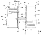
- the exchange system 40 includes a first detection unit 71, a second detection unit 72, a determination unit 61, and a guide unit 62.
- the first detection unit 71 and the second detection unit 72 detect the feeder 20 at detection positions D1 and D2 that are different from each other in the attachment / detachment direction of the feeder 20, respectively.
- the first detection unit 71 includes an optical sensor 711 as a first sensor provided in the apparatus main body 51.
- the second detection unit 72 includes an optical sensor 721 as a second sensor provided in the component mounting machine 10.
- the optical sensors 711 and 721 receive light projected in a direction intersecting with the attaching / detaching direction of the feeder 20 (X direction in the present embodiment), and detect the presence or absence of the feeder 20 at the detection position.
- the optical sensor 711 of the first detection unit 71 detects the feeder 20 at a first detection position D1 that is separated by a predetermined distance L1 from the end of the feeder 20 located at the accommodation position Pa to the equipment position Pe side ( (See states Y1 and Y2 in FIG. 4).
- the optical sensor 721 of the second detection unit 72 detects the feeder 20 at a second detection position D2 that is separated from the end of the feeder 20 located at the equipment position Pe by a predetermined distance L2 toward the accommodation position Pa (state of FIG. 4). See Y4, Y5).
- the first detection unit 71 detects the protrusion of the feeder 20 from the apparatus main body 51. Further, the second detection unit 72 detects the protrusion of the feeder 20 from the component mounting machine 10.
- the detection width of the optical sensor 721 of the second detection unit 72 is set wider than the width of the upper slot 121 in the X direction. Accordingly, the second detection unit 72 is configured to be able to detect the feeder 20 protruding from any of the upper slots 121.
- the distance Ld between the first detection position D1 and the second detection position D2 is set to be smaller than the length Lf of the feeder 20. According to such a configuration, a space where the feeder 20 cannot be detected can be eliminated between the first detection position D1 and the second detection position D2.
- the feeder 20 is detected by at least one of the first detection unit 71 and the second detection unit 72 in a state where the feeder 20 is not located at either the accommodation position Pa or the equipment position Pe.
- the determination unit 61 and the guide unit 62 are incorporated in the control device 60 of the exchange device 50 as shown in FIG.
- the determination unit 61 determines whether or not the feeder 20 has been normally exchanged between the apparatus main body 51 and the component mounting machine 10. Determine whether. More specifically, when only the first detection unit 71 detects the feeder 20 as shown in the state Y2 in FIG. 4, the determination unit 61 and the first detection unit 71 and the first detection unit 61 as shown in the state Y3 in FIG.
- the replacement process is not normally performed and ends abnormally. judge.
- the determination unit 61 indicates that both the detection result of the first detection unit 71 and the detection result of the second detection unit 72 do not detect the feeder 20. If it is, it is determined that the exchange process has been performed normally.
- FIG. 4 shows the respective states of the same feeder 20 shifted in the X direction. Therefore, the position of the feeder 20 in the X direction in the states Y1-Y5 in FIG. 4 is the same.
- the guide unit 62 is recognized based on the detection result of the first detection unit 71 and the detection result of the second detection unit 72 when the determination unit 61 determines that the replacement process of the feeder 20 has not been performed normally.
- the state of the feeder 20 is guided to the operator. In the “state of the feeder 20”, the position of the feeder 20 in the attaching / detaching direction, whether the holding unit 52 holds the feeder 20, and whether the feeder 20 can communicate with the component mounting machine 10. And so on.
- the guide unit 62 guides the position of the feeder 20 that is determined based on the detection result of the first detection unit 71 and the detection result of the second detection unit 72. Further, the guide unit 62 may guide the error processing information to the operator in addition to or instead of the state of the feeder 20 as described above.
- the error processing information indicates a recovery operation for the exchange processing that has ended abnormally, and is changed according to the state of the feeder 20.
- the guidance part 62 may display the information to guide on the management apparatus 6, and may display it on terminal devices, such as a portable terminal (smart phone, tablet terminal) which an operator hold
- terminal devices such as a portable terminal (smart phone, tablet terminal) which an operator hold
- the replacement element that is the target of the replacement process is the feeder 20 that is mounted on the component mounting machine 10 as described above.
- the feeder 20 is detached from the apparatus main body 51 of the replacement apparatus 50 in the upper slot 121 or the lower slot 122 of the component supply apparatus 12 and, conversely, is detached from the component supply apparatus 12 to the apparatus main body 51.
- a collection operation Here, the replenishment operation in the exchange process will be described.
- the exchange device 50 is in a state where the feeder 20 to be installed is accommodated in the device main body 51 from the lower slot 122 of the feeder storage device 5 or the component supply device 12.
- the control device 60 detects the feeder 20 held by the standard sensor 54 in the holding unit 52, and based on the result that the two optical sensors 711 and 721 do not detect the feeder 20, the feeder Recognizing that 20 is in a normal containment state.
- the control device 60 first positions the replacement device 50 as shown in FIG. 5 (S11). Specifically, the control device 60 operates the moving device 53 based on the current position of the exchange device 50 in the X direction. Thereby, the feeder 20 held by the holding unit 52 is positioned corresponding to the position of the upper slot 121 to be equipped. Next, the control device 60 operates the holding unit 52 to move the feeder 20 held by the holding unit 52 to the equipment position Pe (S12).
- the control device 60 releases the state in which the holding unit 52 holds the feeder 20, and returns the holding unit 52 to the apparatus main body 51 side (S13).
- the determination unit 61 determines whether or not the feeder 20 has been normally exchanged between the apparatus main body 51 and the component mounting machine 10. Is determined (S14). Specifically, the determination unit 61 assumes that the standard sensor 54 has not detected the feeder 20 because the replenishment operation has been performed, and the first detection unit 71 and the second detection unit 72 both remove the feeder 20. If not detected (state Y1 or state Y5 in FIG. 4), it is determined that the replacement process has been performed normally (S14: Yes).
- the determination unit 61 performs the replacement process normally. It is determined that the process ended abnormally (S14: No).
- the control device 60 executes error processing when the replacement processing ends abnormally (S15). In the present embodiment, the above error processing stops the operation of the holding unit 52 and the moving device 53 in the exchange device 50 and restricts the operation from the current state.
- the guide unit 62 guides the status of the feeder 20 and error processing information (S16). Specifically, the guide unit 62 sets the position of the feeder 20 determined based on the detection result of the first detection unit 71 and the detection result of the second detection unit 72 to the state of the feeder 20, and in the equipment operation of the replacement process The operator is informed of the position of the feeder 20. Further, the guide unit 62 presents a restoration work corresponding to the state of the feeder 20.
- the replacement system 40 includes an apparatus main body 51 that houses a replacement element (feeder 20) that is detachably mounted on the component mounting machine 10, holds the replacement element, and attaches / detaches the replacement element.
- a holding unit 52 provided in the apparatus main body 51 so as to be movable in the direction, a first detection unit 71 and a second detection unit 72 for detecting the exchange element at different detection positions in the attachment / detachment direction of the exchange element, and a first detection unit 71 based on the detection result of 71 and the detection result of the second detection unit 72, a determination unit 61 that determines whether or not the replacement process of the replacement element has been normally performed between the apparatus main body 51 and the component mounting machine 10. Is provided.
- the exchange device 50 holds a replacement element (feeder 20) that is detachably mounted on the component mounting machine 10, holds the replacement element, and is movable in the attachment / detachment direction of the replacement element.
- a first detection section 71 provided in the apparatus main body 51 for detecting the replacement element at a predetermined detection position in the attaching / detaching direction of the replacement element, and the component mounting machine 10.
- a determination unit 61 that determines whether or not the replacement process of the replacement element has been normally performed between the apparatus main body 51 and the component mounting machine 10.
- the replacement element (feeder 20) is detected by the first detection unit 71 and the second detection unit 72 at detection positions D1 and D2 having different attachment / detachment directions.
- Embodiments 8-1 Modifications of Embodiments 8-1.
- the 1st detection part 71 and the 2nd detection part 72 In the embodiment, it was set as the structure by which the 1st detection part 71 is provided in the apparatus main body 51 of the exchange apparatus 50, and the 2nd detection part 72 is provided in the component mounting machine 10.
- the 1st detection part 71 and the 2nd detection part 72 can employ
- the first detection unit 71 and the second detection unit 72 may both be provided in the exchange device 50.
- the first detection unit 71 and the second detection unit 72 are shared for the exchange process between the plurality of component mounting machines 10 and the feeder storage device 5.
- the first detection unit 71 and the second detection unit 72 may be provided in the component mounting machine 10. Thereby, the positional relationship between the first detection unit 71 and the second detection unit 72 is fixed, and the detection accuracy can be improved.
- the first detection unit 71 and the second detection unit 72 have optical sensors 711 and 721.
- the 1st detection part 71 and the 2nd detection part 72 are good also as a structure which has a contact sensor, an ultrasonic sensor, etc.
- the second detection unit 72 may be configured to also use the height sensor 16 of the component mounting machine 10 as a second sensor provided in the component mounting machine 10.
- the replacement device 50 moves the height sensor 16 to above the feeder 20 and detects the height of the feeder 20 by the height sensor 16.
- a request is made to the machine 10.
- a position shifted from the feeder 20 located at the equipment position Pe toward the accommodation position Pa may be set as the second detection position D2.
- the second detection unit 72 detects the feeder 20 based on the detection result of the height sensor 16. According to such a configuration, the same effects as in the embodiment can be obtained. In addition, since the existing height sensor 16 can be used, the equipment cost can be reduced.
- the first detection unit 71 and the second detection unit 72 may detect the feeder 20 based on the result of the image processing. Specifically, the first detection unit 71 and the second detection unit 72, instead of the optical sensors 711 and 721, perform image processing on image data acquired by imaging with a camera including the detection position in the camera field of view, thereby feeding the feeder. 20 is detected. Thereby, the determination unit 61 can recognize the state of the feeder 20.
- the camera described above may be diverted from the substrate camera 15 provided on the moving table 131 of the head driving device 13.
- the second detection unit 72 may detect the feeder 20 based on the result of communication availability determination between the component mounting machine 10 and the feeder 20. However, when it is determined whether or not the replenishment operation of the replacement process has been normally performed, the feeder 20 is installed in the upper slot 121 to be powered up and activated to some extent until it can communicate with the component mounting machine 10. Takes time. Therefore, the aspect illustrated in the embodiment is preferable from the viewpoint of immediately determining whether the replacement process is right or wrong.
- the exchange system 40 is configured to include two detection units (a first detection unit 71 and a second detection unit 72).
- the exchange system 40 may include three or more detection units, and may recognize the state of the feeder 20 in combination based on the detection results. Further, the detection result of the standard sensor 54 may be used to determine whether the replacement process is correct.
- the replacement element that is to be replaced by the replacement system 40 and the replacement device 50 is the feeder 20 that is mounted on the component mounting machine 10 and supplies components mounted on the board 90.
- the exchange system 40 and the exchange device 50 may use elements other than the feeder 20 as exchange elements.
- the tape reel 23, the nozzle station 35, the waste tape collection container, and the like that are replaceably mounted on the component mounting machine 10 can be the replacement elements.
- the exchanging device 50 automatically exchanges the tape reel 23 of the feeder, thereby enabling accurate delivery of the tape reel.
- the nozzle station needs to hold the suction nozzle 31 corresponding to the type of component used for the production of the substrate product. Therefore, by arranging a storage device for the nozzle station in the production line 1 and enabling the nozzle station to be automatically exchanged between the storage device and the component mounting machine 10, the production efficiency in the production line 1 can be improved.
- the above-mentioned waste tape collection container is a container that is equipped, for example, below the upper slot 121 of the component mounting machine 10 and collects the waste tape generated when each feeder 20 supplies the components.
- This waste tape is, for example, a part of the carrier tape 22 from which a part has been removed is appropriately cut to a length.
- the capacity of the waste tape collection container is limited. Therefore, it is useful from the viewpoint of maintaining a good production state, for example, to maintain the amount of waste tape collected by the waste tape collection container below a certain level using the exchange device 50.
- the exchange device 50 may be configured to supply a stick and collect an empty stick. Further, when the feeder 20 is a bulk feeder, the exchange device 50 may be configured to supply a bulk component or a component case that accommodates the bulk component and collect an empty component case. Even in such a configuration, the replacement element can be automatically supplied and recovered, and the production efficiency in the production line 1 can be improved.
- control device 60 of the exchange device 50 is configured to execute the error process (S15) when the exchange process is not performed normally (S14: No).
- the control device 60 may execute a recovery process.
- the feeder 20 is moved again to the accommodation position Pa or the equipment position Pe according to the state of the feeder 20 based on the detection result of the first detection unit 71 and the detection result of the second detection unit 72. Contains actions to try.
- the feeder 20 adjacent to the collected feeder 20 in the exchange operation of the exchange process is moved due to being caught and the exchange process ends abnormally.
- the collected feeder 20 is not detected by the first detection unit 71 but is detected by the standard sensor 54.
- the adjacent feeder 20 that has been moved by the catch is detected by the second detection unit 72.
- the determination unit 61 determines that the replacement process has not been performed normally.
- the control device 60 performs image processing on the image data acquired by the imaging of the substrate camera 15 provided on the movable table 131, or the height.
- the feeder 20 moved from the equipment position Pe may be specified.
- the guide unit 62 acquires the detection result of the first detection unit 71 and the detection result of the second detection unit 72 again, and the feeder 20 based on these results. You may guide the state of. Specifically, the guide unit 62 presents specific information and status of the feeder 20 and whether or not the moving device 53 is operable as guidance information to the worker. In addition, the guide unit 62 may omit the guide process when an error in the exchange process is resolved by, for example, the recovery process.
- the determination unit 61 and the guide unit 62 are configured to be incorporated in the control device 60 of the exchange device 50.
- the determination part 61 and the guidance part 62 can acquire the detection result of the 1st detection part 71, and the detection result of the 2nd detection part 72, the feeder connected so that it could communicate with the exchange apparatus 50, for example It is good also as a structure integrated in the storage apparatus 5 or the management apparatus 6 of the production line 1.
- the replacement device 50 is configured to be applied to the production line 1 including a plurality of component mounting machines 10.
- the exchanging device 50 may be configured to be dedicated to one component mounting machine 10 and replace the feeder 20 between the upper slot 121 and the lower slot 122. At this time, the same effect can be obtained even if the exchange device 50 uses an element other than the feeder 20 as an exchange element as described above.
Abstract
This replacement system is provided with: a device main body which houses a replacement element attachably/detachably mounted in a component mounter; a holding unit which holds the replacement element and is provided in the device main body to be movable in the attachment/detachment direction of the replacement element; a first detection unit and a second detection unit which respectively detect the replacement element at detection positions different from each other in the attachment/detachment direction of the replacement element; and a determination unit which, on the basis of a detection result from the first detection unit and a detection result from the second detection unit, determines whether or not replacement processing for the replacement element is normally performed between the device main body and the component mounter.
Description
本発明は、交換システムおよび交換装置に関するものである。
The present invention relates to an exchange system and an exchange device.
交換装置が構成する交換システムは、部品装着機に装備される交換要素の交換に用いられる。特許文献1には、部品装着機との間でフィーダの回収および補給を自動で行う補給装置としての交換装置が開示されている。このような交換装置は、例えば装置本体に設けられた検出センサにより収容状態のフィーダを検出可能とし、検出センサによる検出結果に基づいてフィーダが装置本体に収容された状態か、部品装着機に装備された状態かを認識する。
The exchange system configured by the exchange device is used for exchanging exchange elements installed in the component mounting machine. Patent Document 1 discloses an exchange device as a replenishing device that automatically collects and replenishes feeders with a component mounting machine. Such an exchange device, for example, can detect a feeder in an accommodation state by a detection sensor provided in the device main body, and is in a state where the feeder is accommodated in the device main body based on a detection result by the detection sensor, or is equipped in a component mounting machine Recognize whether it has been done.
上記のような交換システムにおいて、交換処理における交換要素の移動軌道上に異物が混入するなどの不測の事態によって交換要素の移動が阻害されるおそれがある。これにより、交換要素が収容状態でも装備状態でもなくなると、その後の交換装置の動作に影響するおそれがある。
In the exchange system as described above, there is a possibility that the movement of the exchange element may be hindered due to an unexpected situation such as foreign matter entering the movement path of the exchange element in the exchange process. As a result, if the replacement element is neither in the housed state nor in the equipped state, there is a risk of affecting the subsequent operation of the replacement device.
本明細書は、交換要素の状態をより正確に把握することにより交換処理の成否を判定可能な交換システムおよび交換装置を提供することを目的とする。
This specification aims to provide an exchange system and an exchange device that can determine the success or failure of the exchange process by more accurately grasping the state of the exchange element.
本明細書は、部品装着機に着脱可能に装備される交換要素を収容する装置本体と、前記交換要素を保持し、前記交換要素の着脱方向に移動可能に前記装置本体に設けられる保持部と、前記交換要素の着脱方向において互いに異なる検出位置で前記交換要素をそれぞれ検出する第一検出部および第二検出部と、前記第一検出部の検出結果および前記第二検出部の検出結果に基づいて、前記装置本体と前記部品装着機との間で前記交換要素の交換処理が正常に行われたか否かを判定する判定部と、を備える、交換システムを開示する。
The present specification includes an apparatus main body that accommodates an exchange element that is detachably mounted on a component mounting machine, and a holding unit that holds the exchange element and is movable in the attachment / detachment direction of the exchange element. , Based on a first detection unit and a second detection unit that detect the replacement element at detection positions different from each other in the attaching / detaching direction of the replacement element, a detection result of the first detection unit, and a detection result of the second detection unit, respectively. And a determination unit that determines whether or not the replacement process of the replacement element has been normally performed between the apparatus main body and the component mounting machine.
本明細書は、部品装着機に着脱可能に装備される交換要素を収容する装置本体と、前記交換要素を保持し、前記交換要素の着脱方向に移動可能に前記装置本体に設けられる保持部と、前記装置本体に設けられ、前記交換要素の着脱方向における所定の検出位置で前記交換要素を検出する第一検出部と、前記部品装着機に設けられた第二検出部であって前記交換要素の着脱方向において前記第一検出部とは異なる検出位置で前記交換要素を検出する前記第二検出部の検出結果、および前記第一検出部の検出結果に基づいて、前記装置本体と前記部品装着機との間で前記交換要素の交換処理が正常に行われたか否かを判定する判定部と、を備える、交換装置を開示する。
The present specification includes an apparatus main body that accommodates an exchange element that is detachably mounted on a component mounting machine, and a holding unit that holds the exchange element and is movable in the attachment / detachment direction of the exchange element. A first detection unit provided in the apparatus main body for detecting the replacement element at a predetermined detection position in the attaching / detaching direction of the replacement element, and a second detection unit provided in the component mounting machine, wherein the replacement element The apparatus main body and the component mounting based on the detection result of the second detection unit that detects the exchange element at a detection position different from the first detection unit in the attaching / detaching direction, and the detection result of the first detection unit And a determination unit that determines whether or not the exchange process of the exchange element has been normally performed with the machine.
このような構成によると、第一検出部および第二検出部により着脱方向の異なる検出位置において交換要素が検出される。これにより、交換処理の実行による交換要素の状態をより正確に把握することができる。よって、交換処理の成否の判定が可能となる。
According to such a configuration, the replacement element is detected by the first detection unit and the second detection unit at detection positions having different attachment / detachment directions. Thereby, the state of the exchange element by execution of exchange processing can be grasped more correctly. Therefore, the success or failure of the exchange process can be determined.
1.交換システムおよび交換装置の概要
以下、交換システムおよび交換装置を具体化した実施形態について図面を参照して説明する。交換装置が構成する交換システムは、部品装着機に装備される種々の交換要素の少なくとも一つを対象として、部品装着機との間で交換要素の交換をする。本実施形態において、複数の部品装着機により構成された生産ラインに交換システムが適用された態様を例示する。 1. Overview of Exchange System and Exchange Device Hereinafter, an embodiment embodying an exchange system and an exchange device will be described with reference to the drawings. An exchange system constituted by an exchange apparatus exchanges exchange elements with a component placement machine for at least one of various exchange elements installed in the component placement machine. In this embodiment, the aspect by which the exchange system was applied to the production line comprised by the some component mounting machine is illustrated.
以下、交換システムおよび交換装置を具体化した実施形態について図面を参照して説明する。交換装置が構成する交換システムは、部品装着機に装備される種々の交換要素の少なくとも一つを対象として、部品装着機との間で交換要素の交換をする。本実施形態において、複数の部品装着機により構成された生産ラインに交換システムが適用された態様を例示する。 1. Overview of Exchange System and Exchange Device Hereinafter, an embodiment embodying an exchange system and an exchange device will be described with reference to the drawings. An exchange system constituted by an exchange apparatus exchanges exchange elements with a component placement machine for at least one of various exchange elements installed in the component placement machine. In this embodiment, the aspect by which the exchange system was applied to the production line comprised by the some component mounting machine is illustrated.
2.生産ライン1の構成
生産ライン1は、図1に示すように、複数の部品装着機10が基板90の搬送方向(X方向)に並んで設置されて構成される。生産ライン1の基板搬入側(図1の左上側)には、カセット式のフィーダ20の保管に用いられるフィーダ保管装置5が設置される。また、生産ライン1には、例えばスクリーン印刷機や実装検査機、リフロー炉などが含まれ得る。 2. Configuration ofProduction Line 1 As shown in FIG. 1, the production line 1 is configured by installing a plurality of component mounting machines 10 side by side in the conveyance direction (X direction) of the substrate 90. A feeder storage device 5 used for storing the cassette-type feeder 20 is installed on the substrate carry-in side of the production line 1 (upper left side in FIG. 1). The production line 1 can include, for example, a screen printing machine, a mounting inspection machine, a reflow furnace, and the like.
生産ライン1は、図1に示すように、複数の部品装着機10が基板90の搬送方向(X方向)に並んで設置されて構成される。生産ライン1の基板搬入側(図1の左上側)には、カセット式のフィーダ20の保管に用いられるフィーダ保管装置5が設置される。また、生産ライン1には、例えばスクリーン印刷機や実装検査機、リフロー炉などが含まれ得る。 2. Configuration of
本実施形態において、生産ライン1には、複数の部品装着機10およびフィーダ保管装置5のそれぞれに対して所定の作業を行う作業装置としての交換装置50が適用される。生産ライン1を構成する各装置および交換装置50は、図示しないネットワークを介して管理装置6と種々のデータを入出力可能に構成されている。交換装置50の詳細構成については後述する。
In the present embodiment, the production line 1 is applied with an exchange device 50 as a working device that performs a predetermined work on each of the plurality of component mounting machines 10 and the feeder storage device 5. Each device and the exchange device 50 constituting the production line 1 are configured to be able to input / output various data to / from the management device 6 via a network (not shown). The detailed configuration of the exchange device 50 will be described later.
フィーダ保管装置5は、複数のスロットを有し、当該スロットにセットされたフィーダ20をストックする。フィーダ20がフィーダ保管装置5にセットされると、フィーダ20と管理装置6との間で通信可能な状態となる。これにより、フィーダ保管装置5のスロットと当該スロットにセットされたフィーダ20の識別符号(ID)が関連付けられて、管理装置6に記録される。
The feeder storage device 5 has a plurality of slots, and stocks the feeders 20 set in the slots. When the feeder 20 is set in the feeder storage device 5, communication between the feeder 20 and the management device 6 is possible. As a result, the slot of the feeder storage device 5 and the identification code (ID) of the feeder 20 set in the slot are associated with each other and recorded in the management device 6.
管理装置6は、生産ライン1の動作状況を監視し、部品装着機10およびフィーダ保管装置5を含む生産設備の制御を行う。管理装置6には、部品装着機10を制御するための各種データが記憶されている。管理装置6は、各生産設備における生産処理の実行に際して、制御プログラムなどの各種データを各生産設備に適宜送出する。
The management device 6 monitors the operation status of the production line 1 and controls production facilities including the component mounting machine 10 and the feeder storage device 5. The management device 6 stores various data for controlling the component mounting machine 10. The management device 6 appropriately sends various data such as a control program to each production facility when executing production processing in each production facility.
3.部品装着機10の構成
生産ライン1を構成する複数の部品装着機10は、図2および図3に示すように、基板搬送装置11と、部品供給装置12と、ヘッド駆動装置13と、部品カメラ14と、基板カメラ15と、高さセンサ16とを備える。以下の説明において、部品装着機10の水平幅方向であり基板90の搬送方向をX方向とし、部品装着機10の水平奥行き方向をY方向とし、X方向およびY方向に垂直な鉛直方向(図1の上下方向)をZ方向とする。 3. Configuration ofComponent Mounting Machine 10 As shown in FIGS. 2 and 3, a plurality of component mounting machines 10 constituting the production line 1 includes a substrate transfer device 11, a component supply device 12, a head driving device 13, and a component camera. 14, a substrate camera 15, and a height sensor 16. In the following description, the horizontal direction of the component mounting machine 10, the transport direction of the substrate 90 is the X direction, the horizontal depth direction of the component mounting machine 10 is the Y direction, and a vertical direction perpendicular to the X direction and the Y direction (see FIG. (Vertical direction of 1) is the Z direction.
生産ライン1を構成する複数の部品装着機10は、図2および図3に示すように、基板搬送装置11と、部品供給装置12と、ヘッド駆動装置13と、部品カメラ14と、基板カメラ15と、高さセンサ16とを備える。以下の説明において、部品装着機10の水平幅方向であり基板90の搬送方向をX方向とし、部品装着機10の水平奥行き方向をY方向とし、X方向およびY方向に垂直な鉛直方向(図1の上下方向)をZ方向とする。 3. Configuration of
基板搬送装置11は、ベルトコンベアおよび位置決め装置などにより構成される。基板搬送装置11は、基板90を搬送方向へと順次搬送するとともに、機内の所定位置に基板90を位置決めする。基板搬送装置11は、部品装着機10による装着処理が終了した後に、基板90を部品装着機10の機外に搬出する。
The substrate transfer device 11 is constituted by a belt conveyor and a positioning device. The substrate transport apparatus 11 sequentially transports the substrates 90 in the transport direction and positions the substrate 90 at a predetermined position in the machine. After the mounting process by the component mounting machine 10 is completed, the board transfer device 11 carries the board 90 out of the component mounting machine 10.
部品供給装置12は、基板90に装着される部品を供給する。部品供給装置12は、フィーダ20を装備可能な上部スロット121および下部スロット122を有する。上部スロット121は、部品装着機10の前部側の上部に配置され、装備されたフィーダ20を動作可能に保持する。つまり、上部スロット121に装備されたフィーダ20は、部品装着機10による装着処理において動作を制御され、当該フィーダ20の上部の規定位置に設けられた取り出し部において部品を供給する。
The component supply device 12 supplies components to be mounted on the substrate 90. The component supply device 12 has an upper slot 121 and a lower slot 122 in which the feeder 20 can be mounted. The upper slot 121 is disposed at the upper part on the front side of the component mounting machine 10 and holds the equipped feeder 20 in an operable manner. In other words, the feeder 20 installed in the upper slot 121 is controlled in operation in the mounting process by the component mounting machine 10, and supplies the component at the take-out portion provided at a predetermined position on the feeder 20.
下部スロット122は、上部スロット121の下方に配置され、装備されたフィーダ20をストックする。つまり、下部スロット122は、生産に用いられるフィーダ20を予備的に保持し、または生産に用いられた使用済みのフィーダ20を一時的に保持する。なお、上部スロット121と下部スロット122との間でのフィーダ20の交換は、後述する交換装置50による自動交換、または作業者による手動交換によりなされる。
The lower slot 122 is arranged below the upper slot 121 and stocks the equipped feeder 20. That is, the lower slot 122 preliminarily holds the feeder 20 used for production, or temporarily holds the used feeder 20 used for production. The feeder 20 is exchanged between the upper slot 121 and the lower slot 122 by automatic exchange by an exchange device 50 described later or manual exchange by an operator.
ヘッド駆動装置13は、部品供給装置12により供給された部品を、基板搬送装置11により機内に搬入された基板90上の所定の装着位置まで移載する。ヘッド駆動装置13は、直動機構により移動台131を水平方向(X軸方向およびY軸方向)に移動させる。移動台131には、図示しないクランプ部材により装着ヘッド30が交換可能に固定される。装着ヘッド30は、部品を採取するとともに、部品の上下方向位置および角度を調整して基板90に装着する。
The head driving device 13 transfers the component supplied by the component supply device 12 to a predetermined mounting position on the substrate 90 carried into the apparatus by the substrate transfer device 11. The head drive device 13 moves the moving base 131 in the horizontal direction (X-axis direction and Y-axis direction) by the linear motion mechanism. The mounting head 30 is fixed to the movable table 131 in a replaceable manner by a clamp member (not shown). The mounting head 30 collects components and adjusts the vertical position and angle of the components to mount them on the substrate 90.
詳細には、装着ヘッド30には、フィーダ20により供給される部品を保持する保持部材が取り付けられる。上記の保持部材には、例えば負圧を供給されて部品を保持する吸着ノズル31や、部品を把持して保持するチャックなどが適用され得る。装着ヘッド30は、保持部材をZ方向に移動可能に、且つZ軸に平行なθ軸周りに回転可能に保持する。装着ヘッド30は、ヘッド駆動装置13の直動機構によりXY方向に移動される。
Specifically, the mounting head 30 is attached with a holding member that holds components supplied by the feeder 20. As the holding member, for example, a suction nozzle 31 that is supplied with a negative pressure to hold a component, a chuck that holds and holds the component, and the like can be applied. The mounting head 30 holds the holding member so as to be movable in the Z direction and rotatable about a θ axis parallel to the Z axis. The mounting head 30 is moved in the XY directions by the linear motion mechanism of the head driving device 13.
部品カメラ14、および基板カメラ15は、CMOSなどの撮像素子を有するデジタル式の撮像装置である。部品カメラ14、および基板カメラ15は、制御信号に基づいて撮像を行い、当該撮像により取得した画像データを送出する。部品カメラ14は、装着ヘッド30の吸着ノズル31に保持された部品を下方から撮像可能に構成される。基板カメラ15は、基板90を上方から撮像可能に構成される。
The component camera 14 and the substrate camera 15 are digital imaging devices having an imaging device such as a CMOS. The component camera 14 and the board camera 15 capture an image based on the control signal and send out image data acquired by the image capture. The component camera 14 is configured to be able to image a component held by the suction nozzle 31 of the mounting head 30 from below. The substrate camera 15 is configured to be able to image the substrate 90 from above.
高さセンサ16は、移動台131に設けられる。高さセンサ16は、鉛直下方に位置する対象物までの距離を測定することにより、対象物から装着ヘッド30までの高さを測定する。高さセンサ16は、例えばレーザー光を用いた光センサなどが採用し得る。また、上記の「対象物」には、例えば基板搬送装置11により位置決めされた基板90や、基板90に装着された部品、部品供給装置12により供給された状態の部品などが含まれ得る。
The height sensor 16 is provided on the movable table 131. The height sensor 16 measures the height from the object to the mounting head 30 by measuring the distance to the object located vertically below. As the height sensor 16, for example, an optical sensor using laser light or the like can be adopted. In addition, the “object” may include, for example, the substrate 90 positioned by the substrate transport device 11, components mounted on the substrate 90, components supplied by the component supply device 12, and the like.
上記のような構成からなる部品装着機10は、部品を基板90に装着する装着処理を実行する。装着処理において、部品装着機10は、画像処理の結果や各種センサによる検出結果、予め記憶された制御プログラムなどに基づき、ヘッド駆動装置13に制御信号を送出する。これにより、装着ヘッド30に支持された複数の吸着ノズル31の位置および角度が制御される。
The component mounting machine 10 configured as described above executes a mounting process for mounting a component on the substrate 90. In the mounting process, the component mounting machine 10 sends a control signal to the head driving device 13 based on the result of image processing, the detection results of various sensors, a control program stored in advance, and the like. Thereby, the position and angle of the plurality of suction nozzles 31 supported by the mounting head 30 are controlled.
なお、装着ヘッド30に保持される吸着ノズル31は、装着処理において基板90に装着される部品の種別に応じて適宜変更される。部品装着機10は、実行する装着処理にて用いる吸着ノズル31が装着ヘッド30に保持されていない場合に、ノズルステーション35に収容されている吸着ノズル31を装着ヘッド30に保持させる。上記のノズルステーション35は、部品装着機10の機内の所定位置に着脱可能に装備される。
The suction nozzle 31 held by the mounting head 30 is appropriately changed according to the type of component mounted on the substrate 90 in the mounting process. The component mounting machine 10 causes the mounting head 30 to hold the suction nozzle 31 accommodated in the nozzle station 35 when the suction nozzle 31 used in the mounting process to be executed is not held by the mounting head 30. The nozzle station 35 is detachably mounted at a predetermined position in the component mounting machine 10.
4.フィーダ20の構成
フィーダ20は、多数の部品が収納されたキャリアテープを送り移動させて、部品を採取可能に供給する。フィーダ20のケース21は、全体形状としては矩形状に形成されている。ケース21は、キャリアテープ22が巻回されたテープリール23を着脱可能に保持する。キャリアテープ22は、送り方向に一定の間隔で形成された複数のキャビティに部品を収納する。 4). Configuration ofFeeder 20 Feeder 20 feeds and moves a carrier tape containing a large number of parts so that the parts can be collected. The case 21 of the feeder 20 is formed in a rectangular shape as a whole. The case 21 detachably holds a tape reel 23 around which the carrier tape 22 is wound. The carrier tape 22 stores components in a plurality of cavities formed at regular intervals in the feed direction.
フィーダ20は、多数の部品が収納されたキャリアテープを送り移動させて、部品を採取可能に供給する。フィーダ20のケース21は、全体形状としては矩形状に形成されている。ケース21は、キャリアテープ22が巻回されたテープリール23を着脱可能に保持する。キャリアテープ22は、送り方向に一定の間隔で形成された複数のキャビティに部品を収納する。 4). Configuration of
また、フィーダ20は、部品供給装置12の上部スロット121または下部スロット122に装備されると、コネクタを介して部品装着機10から電力が供給される。そして、フィーダ20は、部品装着機10との間で通信可能な状態となる。フィーダ20は、部品装着機10による制御指令などに基づいて、キャリアテープ22の送り動作を制御する。これにより、フィーダ20は、フィーダ20の上部の規定位置に設けられた取り出し部において、装着ヘッド30の保持部材によって部品を採取可能に供給する。
Further, when the feeder 20 is installed in the upper slot 121 or the lower slot 122 of the component supply device 12, electric power is supplied from the component mounting machine 10 via the connector. And the feeder 20 will be in the state which can communicate between the components mounting machines 10. FIG. The feeder 20 controls the feeding operation of the carrier tape 22 based on a control command from the component mounting machine 10. As a result, the feeder 20 supplies the components so as to be collected by the holding member of the mounting head 30 at the take-out portion provided at a predetermined position on the upper portion of the feeder 20.
5.交換システム40および交換装置50の構成
交換システム40は、図1-図3に示すように、第一レール41と、第二レール42と、交換装置50とを備える。第一レール41は、図1に示すように、複数の部品装着機10の前部に設けられる。より詳細には、第一レール41は、複数の部品装着機10のそれぞれにおける上部スロット121と下部スロット122との上下方向の間に設けられる。第二レール42は、部品装着機10の下部スロット122の下方に設けられている。 5. Configuration ofExchange System 40 and Exchange Device 50 The exchange system 40 includes a first rail 41, a second rail 42, and an exchange device 50, as shown in FIGS. As shown in FIG. 1, the first rail 41 is provided at the front of the plurality of component mounting machines 10. More specifically, the first rail 41 is provided between the upper slot 121 and the lower slot 122 in each of the plurality of component mounting machines 10. The second rail 42 is provided below the lower slot 122 of the component mounting machine 10.
交換システム40は、図1-図3に示すように、第一レール41と、第二レール42と、交換装置50とを備える。第一レール41は、図1に示すように、複数の部品装着機10の前部に設けられる。より詳細には、第一レール41は、複数の部品装着機10のそれぞれにおける上部スロット121と下部スロット122との上下方向の間に設けられる。第二レール42は、部品装着機10の下部スロット122の下方に設けられている。 5. Configuration of
上記のような構成からなる第一レール41および第二レール42は、生産ライン1において、基板90の搬送方向の概ね全域に亘って延伸している。これにより、交換装置50は、後述する移動装置53の動作によって、複数の部品装着機10およびフィーダ保管装置5の前面側を含むX方向の任意位置に位置決め可能に構成される。
The first rail 41 and the second rail 42 having the above-described configuration extend over almost the entire region in the transport direction of the substrate 90 in the production line 1. Thereby, the exchange device 50 is configured to be positioned at an arbitrary position in the X direction including the front side of the plurality of component mounting machines 10 and the feeder storage device 5 by the operation of the moving device 53 described later.
交換装置50は、本実施形態において、基板90に装着される部品を供給するフィーダ20を交換要素として、生産ライン1を構成する複数の部品装着機10との間、およびフィーダ保管装置5との間でフィーダ20の交換処理を行う。上記の交換処理には、フィーダ20の回収および補給の少なくとも一方が含まれる。
In the present embodiment, the exchange device 50 is connected to a plurality of component placement machines 10 constituting the production line 1 and to the feeder storage device 5 by using the feeder 20 that supplies the components to be mounted on the substrate 90 as a replacement element. The feeder 20 is exchanged between them. The exchange process includes at least one of collecting and replenishing the feeder 20.
本実施形態において、交換装置50は、フィーダ保管装置5から部品装着機10の上部スロット121または下部スロット122にフィーダ20を搬送する。また、交換装置50は、部品装着機10の上部スロット121と下部スロット122との間でフィーダ20を入れ換える。さらに、交換装置50は、使用済みのフィーダ20を部品装着機10からフィーダ保管装置5に搬送する。
In this embodiment, the exchange device 50 conveys the feeder 20 from the feeder storage device 5 to the upper slot 121 or the lower slot 122 of the component mounting machine 10. Further, the exchange device 50 exchanges the feeder 20 between the upper slot 121 and the lower slot 122 of the component mounting machine 10. Further, the exchange device 50 conveys the used feeder 20 from the component mounting machine 10 to the feeder storage device 5.
交換装置50は、図3に示すように、装置本体51と、保持部52と、移動装置53と、標準センサ54と、制御装置60とを備える。装置本体51は、フィーダ20を収容するとともに、保持部52を保持する。また、装置本体51には、保持部52を動作させる駆動装置(図示しない)が設けられている。
As shown in FIG. 3, the exchange device 50 includes a device main body 51, a holding unit 52, a moving device 53, a standard sensor 54, and a control device 60. The apparatus main body 51 holds the feeder 20 and holds the holding unit 52. Further, the apparatus main body 51 is provided with a drive device (not shown) for operating the holding unit 52.
保持部52は、フィーダ20を保持する。保持部52がフィーダ20を保持する構成としては、フィーダ20のケース21を把持する構成や、ケース21に設けられた係止部と係止する構成、ケース21に設けられた連結部と連結する構成などが採用し得る。保持部52は、フィーダ20の着脱方向(本実施形態においてY方向)に移動可能に装置本体51に設けられる。また、保持部52は、装置本体51に対してZ方向に移動可能に設けられる。保持部52は、制御装置60によりYZ方向位置およびフィーダ20の保持状態を制御される。
The holding unit 52 holds the feeder 20. The holding part 52 holds the feeder 20 as a structure for holding the case 21 of the feeder 20, a structure for locking with a locking part provided in the case 21, and a connection part provided in the case 21. A configuration or the like can be adopted. The holding unit 52 is provided in the apparatus main body 51 so as to be movable in the attaching / detaching direction of the feeder 20 (Y direction in the present embodiment). The holding unit 52 is provided so as to be movable in the Z direction with respect to the apparatus main body 51. The holding unit 52 is controlled by the control device 60 in the YZ direction position and the holding state of the feeder 20.
移動装置53は、生産ライン1における基板90の搬送方向(本実施形態においてX方向)に沿って装置本体51を移動させる。移動装置53は、第一レール41に摩擦により係合する駆動輪(図示しない)を回転させることにより装置本体51を第一レール41に沿って移動させる。このとき、移動装置53は、第二レール42に沿って転動するガイドローラ(図示しない)により装置本体51の姿勢を維持する。移動装置53は、制御装置60によりX方向位置を制御される。
The moving device 53 moves the device main body 51 along the transport direction (X direction in the present embodiment) of the substrate 90 in the production line 1. The moving device 53 moves the device main body 51 along the first rail 41 by rotating a driving wheel (not shown) engaged with the first rail 41 by friction. At this time, the moving device 53 maintains the posture of the device main body 51 by a guide roller (not shown) that rolls along the second rail 42. The position of the moving device 53 is controlled by the control device 60 in the X direction.
標準センサ54は、装置本体51に収容された状態にあるフィーダ20を検出する。上記の「収容された状態」とは、図3の一点鎖線で示すように、着脱方向(Y方向)における収容位置Paにフィーダ20が移動された状態をいう。本実施形態において、標準センサ54は、保持部52に設けられた近接センサである。標準センサ54は、収容位置Paに移動したフィーダ20を非接触で検出する。標準センサ54は、フィーダ20の着脱方向においてフィーダ20が収容位置Paからずれて位置する場合、および保持部52がフィーダ20を保持していない場合にフィーダ20を検出しない。
Standard sensor 54 detects feeder 20 in a state of being accommodated in apparatus main body 51. The above “accommodated state” refers to a state in which the feeder 20 has been moved to the accommodation position Pa in the attaching / detaching direction (Y direction) as indicated by a one-dot chain line in FIG. In the present embodiment, the standard sensor 54 is a proximity sensor provided in the holding unit 52. The standard sensor 54 detects the feeder 20 moved to the accommodation position Pa in a non-contact manner. The standard sensor 54 does not detect the feeder 20 when the feeder 20 is displaced from the accommodation position Pa in the attachment / detachment direction of the feeder 20 and when the holding unit 52 does not hold the feeder 20.
制御装置60は、主として、CPUや各種メモリ、制御回路により構成されるコントローラである。制御装置60は、複数の部品装着機10、フィーダ保管装置5、および管理装置6と通信可能に接続される。制御装置60は、装置本体51のX方向位置、保持部52のYZ方向位置、フィーダ20の保持状態などに基づいて、移動装置53および保持部52を動作させる駆動装置を動作させる。これにより、制御装置60は、交換装置50によるフィーダ20の交換処理を制御する。
The control device 60 is a controller mainly composed of a CPU, various memories, and a control circuit. The control device 60 is communicably connected to the plurality of component mounting machines 10, the feeder storage device 5, and the management device 6. The control device 60 operates the driving device that operates the moving device 53 and the holding unit 52 based on the X-direction position of the device main body 51, the YZ-direction position of the holding unit 52, the holding state of the feeder 20, and the like. Thereby, the control device 60 controls the replacement processing of the feeder 20 by the replacement device 50.
ここで、交換装置50によりフィーダ20の交換処理が正常に行われると、フィーダ20は、装置本体51に収容された状態、または部品装着機10に装備された状態となる。上記の「装備された状態」とは、図3の二点鎖線で示すように、着脱方向(Y方向)における装備位置Peにフィーダ20が移動された状態をいう。制御装置60は、交換処理を行った後に、標準センサ54の検出結果に基づいてフィーダ20が収容位置Paに位置するか否かを認識する。
Here, when the replacement processing of the feeder 20 is normally performed by the replacement device 50, the feeder 20 is in a state of being accommodated in the device main body 51 or mounted in the component mounting machine 10. The above “equipped state” refers to a state in which the feeder 20 has been moved to the equipment position Pe in the attaching / detaching direction (Y direction) as indicated by a two-dot chain line in FIG. 3. After performing the replacement process, the control device 60 recognizes whether the feeder 20 is located at the accommodation position Pa based on the detection result of the standard sensor 54.
しかしながら、フィーダ20の移動軌道上にキャリアテープ22から脱落した部品や廃棄物が異物として混入すると、フィーダ20の移動が阻害されるおそれがある。また、交換処理により回収したあるフィーダ20が隣のフィーダ20に引っ掛かった場合に、その隣のフィーダ20が装備位置Peから僅かに収容位置Pa側に移動するおそれがある。上記のような場合に、交換対象のフィーダ20が収容位置Paに位置するか否かでは、交換処理が正常に行われたか否かを正確に判定できないことがある。
However, if the parts and waste that have fallen off the carrier tape 22 are mixed as foreign matter on the movement track of the feeder 20, the movement of the feeder 20 may be hindered. Further, when a certain feeder 20 collected by the exchange process is caught by the adjacent feeder 20, the adjacent feeder 20 may slightly move from the equipment position Pe to the accommodation position Pa side. In such a case, it may not be possible to accurately determine whether or not the replacement process has been performed normally based on whether or not the feeder 20 to be replaced is located at the storage position Pa.
そこで、交換システム40は、フィーダ20の着脱方向において互いに異なる検出位置でフィーダ20を検出可能とし、その検出結果に基づいて交換処理の正否を判定する構成を採用する。具体的には、交換システム40は、第一検出部71と、第二検出部72と、判定部61と、案内部62とを備える。第一検出部71および第二検出部72は、フィーダ20の着脱方向において互いに異なる検出位置D1,D2でフィーダ20をそれぞれ検出する。
Therefore, the exchange system 40 employs a configuration in which the feeder 20 can be detected at detection positions different from each other in the attachment / detachment direction of the feeder 20 and whether the exchange process is correct or not is determined based on the detection result. Specifically, the exchange system 40 includes a first detection unit 71, a second detection unit 72, a determination unit 61, and a guide unit 62. The first detection unit 71 and the second detection unit 72 detect the feeder 20 at detection positions D1 and D2 that are different from each other in the attachment / detachment direction of the feeder 20, respectively.
具体的には、第一検出部71は、装置本体51に設けられた第一センサとしての光センサ711を有する。同様に、第二検出部72は、部品装着機10に設けられた第二センサとしての光センサ721を有する。光センサ711,721は、フィーダ20の着脱方向に交差する方向(本実施形態においてX方向)に投光された光を受光して、検出位置におけるフィーダ20の有無を検出する。
Specifically, the first detection unit 71 includes an optical sensor 711 as a first sensor provided in the apparatus main body 51. Similarly, the second detection unit 72 includes an optical sensor 721 as a second sensor provided in the component mounting machine 10. The optical sensors 711 and 721 receive light projected in a direction intersecting with the attaching / detaching direction of the feeder 20 (X direction in the present embodiment), and detect the presence or absence of the feeder 20 at the detection position.
詳細には、第一検出部71の光センサ711は、収容位置Paに位置するフィーダ20の端部から装備位置Pe側に所定距離L1だけ離間した第一検出位置D1においてフィーダ20を検出する(図4の状態Y1,Y2を参照)。第二検出部72の光センサ721は、装備位置Peに位置するフィーダ20の端部から収容位置Pa側に所定距離L2だけ離間した第二検出位置D2においてフィーダ20を検出する(図4の状態Y4,Y5を参照)。
Specifically, the optical sensor 711 of the first detection unit 71 detects the feeder 20 at a first detection position D1 that is separated by a predetermined distance L1 from the end of the feeder 20 located at the accommodation position Pa to the equipment position Pe side ( (See states Y1 and Y2 in FIG. 4). The optical sensor 721 of the second detection unit 72 detects the feeder 20 at a second detection position D2 that is separated from the end of the feeder 20 located at the equipment position Pe by a predetermined distance L2 toward the accommodation position Pa (state of FIG. 4). See Y4, Y5).
このような構成によると、第一検出部71は、装置本体51からのフィーダ20のはみ出しを検出する。また、第二検出部72は、部品装着機10からのフィーダ20のはみ出しを検出する。なお、第二検出部72の光センサ721の検出幅は、上部スロット121のX方向幅よりも広く設定される。これにより、第二検出部72は、上部スロット121の何れかからはみ出したフィーダ20を検出可能に構成される。
According to such a configuration, the first detection unit 71 detects the protrusion of the feeder 20 from the apparatus main body 51. Further, the second detection unit 72 detects the protrusion of the feeder 20 from the component mounting machine 10. The detection width of the optical sensor 721 of the second detection unit 72 is set wider than the width of the upper slot 121 in the X direction. Accordingly, the second detection unit 72 is configured to be able to detect the feeder 20 protruding from any of the upper slots 121.
また、フィーダ20の着脱方向において、第一検出位置D1と第二検出位置D2との距離Ldは、フィーダ20の長さLfよりも小さく設定される。このような構成によると、第一検出位置D1と第二検出位置D2との間においてフィーダ20を検出不能なスペースをなくすことができる。換言すると、フィーダ20は、収容位置Paおよび装備位置Peの何れにも位置していない状態では、第一検出部71および第二検出部72の少なくとも一方により検出される。
Further, in the attachment / detachment direction of the feeder 20, the distance Ld between the first detection position D1 and the second detection position D2 is set to be smaller than the length Lf of the feeder 20. According to such a configuration, a space where the feeder 20 cannot be detected can be eliminated between the first detection position D1 and the second detection position D2. In other words, the feeder 20 is detected by at least one of the first detection unit 71 and the second detection unit 72 in a state where the feeder 20 is not located at either the accommodation position Pa or the equipment position Pe.
本実施形態において、判定部61および案内部62は、図3に示すように、交換装置50の制御装置60に組み込まれる。判定部61は、第一検出部71の検出結果および第二検出部72の検出結果に基づいて、装置本体51と部品装着機10との間でフィーダ20の交換処理が正常に行われたか否かを判定する。より詳細には、判定部61は、図4の状態Y2に示すように第一検出部71のみがフィーダ20を検出した場合、図4の状態Y3に示すように、第一検出部71および第二検出部72がともにフィーダ20を検出した場合、および図4の状態Y4に示すように第二検出部72のみがフィーダ20を検出した場合に、交換処理が正常に行われずに異常終了したと判定する。
In the present embodiment, the determination unit 61 and the guide unit 62 are incorporated in the control device 60 of the exchange device 50 as shown in FIG. Based on the detection result of the first detection unit 71 and the detection result of the second detection unit 72, the determination unit 61 determines whether or not the feeder 20 has been normally exchanged between the apparatus main body 51 and the component mounting machine 10. Determine whether. More specifically, when only the first detection unit 71 detects the feeder 20 as shown in the state Y2 in FIG. 4, the determination unit 61 and the first detection unit 71 and the first detection unit 61 as shown in the state Y3 in FIG. When both the two detection units 72 detect the feeder 20 and when only the second detection unit 72 detects the feeder 20 as shown in the state Y4 of FIG. 4, the replacement process is not normally performed and ends abnormally. judge.
一方で、判定部61は、図4の状態Y1および状態Y5に示すように、第一検出部71の検出結果および第二検出部72の検出結果がともにフィーダ20を検出していないとの結果である場合に、交換処理が正常に行われたものと判定する。なお、図4は、同一のフィーダ20のそれぞれの状態をX方向にずらして表示している。よって、図4の状態Y1-Y5におけるフィーダ20のX方向の位置は、同一である。
On the other hand, as shown in the state Y1 and the state Y5 in FIG. 4, the determination unit 61 indicates that both the detection result of the first detection unit 71 and the detection result of the second detection unit 72 do not detect the feeder 20. If it is, it is determined that the exchange process has been performed normally. Note that FIG. 4 shows the respective states of the same feeder 20 shifted in the X direction. Therefore, the position of the feeder 20 in the X direction in the states Y1-Y5 in FIG. 4 is the same.
案内部62は、フィーダ20の交換処理が正常に行われなかったと判定部61により判定された場合に、第一検出部71の検出結果および第二検出部72の検出結果に基づいて認識されるフィーダ20の状態を作業者に案内する。上記の「フィーダ20の状態」には、着脱方向におけるフィーダ20の位置、保持部52がフィーダ20を保持しているか否か、フィーダ20が部品装着機10との間で通信可能であるか否かなどが含まれる。
The guide unit 62 is recognized based on the detection result of the first detection unit 71 and the detection result of the second detection unit 72 when the determination unit 61 determines that the replacement process of the feeder 20 has not been performed normally. The state of the feeder 20 is guided to the operator. In the “state of the feeder 20”, the position of the feeder 20 in the attaching / detaching direction, whether the holding unit 52 holds the feeder 20, and whether the feeder 20 can communicate with the component mounting machine 10. And so on.
本実施形態において、案内部62は、第一検出部71の検出結果および第二検出部72の検出結果に基づいて割り出されるフィーダ20の位置を案内する。また、案内部62は、上記のようなフィーダ20の状態に加えて、または換えて作業者にエラー処理の情報を案内してもよい。エラー処理の情報は、異常終了した交換処理に対する復旧作業などを示すものであり、フィーダ20の状態に応じて変更される。
In the present embodiment, the guide unit 62 guides the position of the feeder 20 that is determined based on the detection result of the first detection unit 71 and the detection result of the second detection unit 72. Further, the guide unit 62 may guide the error processing information to the operator in addition to or instead of the state of the feeder 20 as described above. The error processing information indicates a recovery operation for the exchange processing that has ended abnormally, and is changed according to the state of the feeder 20.
なお、案内部62は、案内する情報を管理装置6に表示してもよいし、作業者が保持する携帯端末(スマートフォン、タブレット端末)などの端末装置に表示してもよい。上記のような構成によると、作業者は、どのような復旧作業を行えばよいかなどを把握できる。これにより、交換処理の異常終了に伴う交換装置50の停止時間を短縮できる。結果として、生産効率の低下を防止できる。
In addition, the guidance part 62 may display the information to guide on the management apparatus 6, and may display it on terminal devices, such as a portable terminal (smart phone, tablet terminal) which an operator hold | maintains. According to the above configuration, the worker can grasp what kind of recovery work should be performed. Thereby, the stop time of the exchange apparatus 50 accompanying the abnormal end of the exchange process can be shortened. As a result, a decrease in production efficiency can be prevented.
6.交換システムによる交換処理
交換システムによる交換処理について図4および図5を参照して説明する。ここで、交換処理の対象である交換要素は、上記と同様に部品装着機10に装備されるフィーダ20とする。また、交換処理には、フィーダ20を交換装置50の装置本体51から部品供給装置12の上部スロット121または下部スロット122に装備する補給動作と、反対に部品供給装置12から装置本体51に離脱させる回収動作とが含まれる。ここでは、交換処理における補給動作を説明する。 6). Exchange Process by Exchange System The exchange process by the exchange system will be described with reference to FIGS. Here, the replacement element that is the target of the replacement process is thefeeder 20 that is mounted on the component mounting machine 10 as described above. In the replacement process, the feeder 20 is detached from the apparatus main body 51 of the replacement apparatus 50 in the upper slot 121 or the lower slot 122 of the component supply apparatus 12 and, conversely, is detached from the component supply apparatus 12 to the apparatus main body 51. And a collection operation. Here, the replenishment operation in the exchange process will be described.
交換システムによる交換処理について図4および図5を参照して説明する。ここで、交換処理の対象である交換要素は、上記と同様に部品装着機10に装備されるフィーダ20とする。また、交換処理には、フィーダ20を交換装置50の装置本体51から部品供給装置12の上部スロット121または下部スロット122に装備する補給動作と、反対に部品供給装置12から装置本体51に離脱させる回収動作とが含まれる。ここでは、交換処理における補給動作を説明する。 6). Exchange Process by Exchange System The exchange process by the exchange system will be described with reference to FIGS. Here, the replacement element that is the target of the replacement process is the
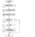
また、交換装置50は、フィーダ保管装置5または部品供給装置12の下部スロット122から装備予定のフィーダ20を装置本体51に収容している状態とする。このとき、制御装置60は、標準センサ54が保持部52に保持されたフィーダ20を検出し、且つ2つの光センサ711,721がともにフィーダ20を検出していないとの結果に基づいて、フィーダ20が正常な収容状態にあることを認識している。
Further, the exchange device 50 is in a state where the feeder 20 to be installed is accommodated in the device main body 51 from the lower slot 122 of the feeder storage device 5 or the component supply device 12. At this time, the control device 60 detects the feeder 20 held by the standard sensor 54 in the holding unit 52, and based on the result that the two optical sensors 711 and 721 do not detect the feeder 20, the feeder Recognizing that 20 is in a normal containment state.
制御装置60は、図5に示すように、先ず交換装置50の位置決めを行う(S11)。具体的には、制御装置60は、交換装置50のX方向の現在位置に基づいて、移動装置53を動作させる。これにより、保持部52に保持されたフィーダ20は、装備予定の上部スロット121の位置に対応して位置決めされる。次に、制御装置60は、保持部52を動作させて、保持部52に保持されたフィーダ20を装備位置Peまで移動させる(S12)。
The control device 60 first positions the replacement device 50 as shown in FIG. 5 (S11). Specifically, the control device 60 operates the moving device 53 based on the current position of the exchange device 50 in the X direction. Thereby, the feeder 20 held by the holding unit 52 is positioned corresponding to the position of the upper slot 121 to be equipped. Next, the control device 60 operates the holding unit 52 to move the feeder 20 held by the holding unit 52 to the equipment position Pe (S12).
続いて、制御装置60は、保持部52がフィーダ20を保持した状態を解除し、保持部52を装置本体51側へと戻す(S13)。判定部61は、第一検出部71の検出結果および第二検出部72の検出結果に基づいて、装置本体51と部品装着機10との間でフィーダ20の交換処理が正常に行われたか否かを判定する(S14)。具体的には、判定部61は、補給動作が行われたことから標準センサ54がフィーダ20を検出していなことを前提とし、第一検出部71および第二検出部72がともにフィーダ20を検出していない場合に(図4の状態Y1または状態Y5)、交換処理が正常に行われたものと判定する(S14:Yes)。
Subsequently, the control device 60 releases the state in which the holding unit 52 holds the feeder 20, and returns the holding unit 52 to the apparatus main body 51 side (S13). Based on the detection result of the first detection unit 71 and the detection result of the second detection unit 72, the determination unit 61 determines whether or not the feeder 20 has been normally exchanged between the apparatus main body 51 and the component mounting machine 10. Is determined (S14). Specifically, the determination unit 61 assumes that the standard sensor 54 has not detected the feeder 20 because the replenishment operation has been performed, and the first detection unit 71 and the second detection unit 72 both remove the feeder 20. If not detected (state Y1 or state Y5 in FIG. 4), it is determined that the replacement process has been performed normally (S14: Yes).
一方で、判定部61は、第一検出部71および第二検出部72の少なくとも一方がフィーダ20を検出している場合に(図4の状態Y2,Y3,Y4)、交換処理が正常に行われずに異常終了したものと判定する(S14:No)。制御装置60は、交換処理が異常終了した場合に、エラー処理を実行する(S15)。本実施形態において、上記のエラー処理により、交換装置50における保持部52および移動装置53の動作が停止されるとともに、現在状態からの動作を規制される。
On the other hand, when at least one of the first detection unit 71 and the second detection unit 72 detects the feeder 20 (states Y2, Y3, and Y4 in FIG. 4), the determination unit 61 performs the replacement process normally. It is determined that the process ended abnormally (S14: No). The control device 60 executes error processing when the replacement processing ends abnormally (S15). In the present embodiment, the above error processing stops the operation of the holding unit 52 and the moving device 53 in the exchange device 50 and restricts the operation from the current state.
また、案内部62は、フィーダ20の状態およびエラー処理の情報を案内する(S16)。詳細には、案内部62は、第一検出部71の検出結果および第二検出部72の検出結果に基づいて割り出されたフィーダ20の位置をフィーダ20の状態とし、交換処理の装備動作においてフィーダ20がどのような位置にあるかがを作業者に提示する。さらに、案内部62は、フィーダ20の状態に応じた復旧作業を提示する。
Further, the guide unit 62 guides the status of the feeder 20 and error processing information (S16). Specifically, the guide unit 62 sets the position of the feeder 20 determined based on the detection result of the first detection unit 71 and the detection result of the second detection unit 72 to the state of the feeder 20, and in the equipment operation of the replacement process The operator is informed of the position of the feeder 20. Further, the guide unit 62 presents a restoration work corresponding to the state of the feeder 20.
7.実施形態の構成による効果
本実施形態の交換システム40は、部品装着機10に着脱可能に装備される交換要素(フィーダ20)を収容する装置本体51と、交換要素を保持し、交換要素の着脱方向に移動可能に装置本体51に設けられる保持部52と、交換要素の着脱方向において互いに異なる検出位置で交換要素をそれぞれ検出する第一検出部71および第二検出部72と、第一検出部71の検出結果および第二検出部72の検出結果に基づいて、装置本体51と部品装着機10との間で交換要素の交換処理が正常に行われたか否かを判定する判定部61と、を備える。 7). Effects of Embodiment Configuration Thereplacement system 40 according to the present embodiment includes an apparatus main body 51 that houses a replacement element (feeder 20) that is detachably mounted on the component mounting machine 10, holds the replacement element, and attaches / detaches the replacement element. A holding unit 52 provided in the apparatus main body 51 so as to be movable in the direction, a first detection unit 71 and a second detection unit 72 for detecting the exchange element at different detection positions in the attachment / detachment direction of the exchange element, and a first detection unit 71 based on the detection result of 71 and the detection result of the second detection unit 72, a determination unit 61 that determines whether or not the replacement process of the replacement element has been normally performed between the apparatus main body 51 and the component mounting machine 10. Is provided.
本実施形態の交換システム40は、部品装着機10に着脱可能に装備される交換要素(フィーダ20)を収容する装置本体51と、交換要素を保持し、交換要素の着脱方向に移動可能に装置本体51に設けられる保持部52と、交換要素の着脱方向において互いに異なる検出位置で交換要素をそれぞれ検出する第一検出部71および第二検出部72と、第一検出部71の検出結果および第二検出部72の検出結果に基づいて、装置本体51と部品装着機10との間で交換要素の交換処理が正常に行われたか否かを判定する判定部61と、を備える。 7). Effects of Embodiment Configuration The
また、本実施形態の交換装置50は、部品装着機10に着脱可能に装備される交換要素(フィーダ20)を収容する装置本体51と、交換要素を保持し、交換要素の着脱方向に移動可能に装置本体51に設けられる保持部52と、装置本体51に設けられ、交換要素の着脱方向における所定の検出位置で交換要素を検出する第一検出部71と、部品装着機10に設けられた第二検出部72であって交換要素の着脱方向において第一検出部71とは異なる検出位置で交換要素を検出する第二検出部72の検出結果、および第一検出部71の検出結果に基づいて、装置本体51と部品装着機10との間で交換要素の交換処理が正常に行われたか否かを判定する判定部61と、を備える。
In addition, the exchange device 50 according to the present embodiment holds a replacement element (feeder 20) that is detachably mounted on the component mounting machine 10, holds the replacement element, and is movable in the attachment / detachment direction of the replacement element. Provided in the apparatus main body 51, a first detection section 71 provided in the apparatus main body 51 for detecting the replacement element at a predetermined detection position in the attaching / detaching direction of the replacement element, and the component mounting machine 10. Based on the detection result of the second detection unit 72 that detects the replacement element at a detection position different from that of the first detection unit 71 in the attachment / detachment direction of the replacement element, and the detection result of the first detection unit 71 A determination unit 61 that determines whether or not the replacement process of the replacement element has been normally performed between the apparatus main body 51 and the component mounting machine 10.
このような構成によると、第一検出部71および第二検出部72により着脱方向の異なる検出位置D1,D2において交換要素(フィーダ20)が検出される。これにより、従来のように収容状態のみを検出する構成と比較して、交換処理の実行による交換要素であるフィーダ20の状態をより正確に把握することができる。よって、交換処理の成否の判定が可能となる。
According to such a configuration, the replacement element (feeder 20) is detected by the first detection unit 71 and the second detection unit 72 at detection positions D1 and D2 having different attachment / detachment directions. Thereby, compared with the structure which detects only an accommodation state like the past, the state of the feeder 20 which is an exchange element by execution of exchange processing can be grasped more correctly. Therefore, the success or failure of the exchange process can be determined.
8.実施形態の変形態様
8-1.第一検出部71および第二検出部72について
実施形態において、第一検出部71が交換装置50の装置本体51に設けられ、第二検出部72が部品装着機10に設けられる構成とした。これに対して、第一検出部71および第二検出部72は、フィーダ20の着脱方向において互いに異なる検出位置D1,D2でフィーダ20をそれぞれ検出可能であれば、種々の態様を採用し得る。 8). Modifications of Embodiments 8-1. About the1st detection part 71 and the 2nd detection part 72 In the embodiment, it was set as the structure by which the 1st detection part 71 is provided in the apparatus main body 51 of the exchange apparatus 50, and the 2nd detection part 72 is provided in the component mounting machine 10. FIG. On the other hand, the 1st detection part 71 and the 2nd detection part 72 can employ | adopt a various aspect, if the feeder 20 can each be detected in the detection positions D1 and D2 which are mutually different in the attachment / detachment direction of the feeder 20. FIG.
8-1.第一検出部71および第二検出部72について
実施形態において、第一検出部71が交換装置50の装置本体51に設けられ、第二検出部72が部品装着機10に設けられる構成とした。これに対して、第一検出部71および第二検出部72は、フィーダ20の着脱方向において互いに異なる検出位置D1,D2でフィーダ20をそれぞれ検出可能であれば、種々の態様を採用し得る。 8). Modifications of Embodiments 8-1. About the
例えば、第一検出部71および第二検出部72は、ともに交換装置50に設けられる構成としてもよい。これにより、交換装置50が移動装置53を備える構成においては、複数の部品装着機10およびフィーダ保管装置5との間での交換処理に第一検出部71および第二検出部72を共用することができる。また、第一検出部71および第二検出部72は、部品装着機10に設けられる構成としてもよい。これにより、第一検出部71および第二検出部72の位置関係が固定され、検出精度の向上を図ることができる。
For example, the first detection unit 71 and the second detection unit 72 may both be provided in the exchange device 50. Thereby, in the configuration in which the exchange device 50 includes the moving device 53, the first detection unit 71 and the second detection unit 72 are shared for the exchange process between the plurality of component mounting machines 10 and the feeder storage device 5. Can do. The first detection unit 71 and the second detection unit 72 may be provided in the component mounting machine 10. Thereby, the positional relationship between the first detection unit 71 and the second detection unit 72 is fixed, and the detection accuracy can be improved.
また、第一検出部71および第二検出部72は、光センサ711,721を有する構成とした。これに対して、第一検出部71および第二検出部72は、接触センサや超音波センサなどを有する構成としてもよい。また、第二検出部72は、部品装着機10に設けられた第二センサとして部品装着機10の高さセンサ16を兼用する構成としてもよい。
Also, the first detection unit 71 and the second detection unit 72 have optical sensors 711 and 721. On the other hand, the 1st detection part 71 and the 2nd detection part 72 are good also as a structure which has a contact sensor, an ultrasonic sensor, etc. Further, the second detection unit 72 may be configured to also use the height sensor 16 of the component mounting machine 10 as a second sensor provided in the component mounting machine 10.
具体的には、交換処理の実行時において、交換装置50は、高さセンサ16をフィーダ20の上方まで移動させるとともに、高さセンサ16によるフィーダ20の高さの検出を行うように、部品装着機10に対して要求を行う。このとき、例えば装備位置Peに位置するフィーダ20から収容位置Pa側にずれた位置を第二検出位置D2としてもよい。そして、第二検出部72は、高さセンサ16の検出結果に基づいて、フィーダ20を検出する。このような構成によると、実施形態と同様の効果を奏する。また、既存の高さセンサ16を流用できるので、設備コストの低減を図ることができる。
Specifically, at the time of executing the replacement process, the replacement device 50 moves the height sensor 16 to above the feeder 20 and detects the height of the feeder 20 by the height sensor 16. A request is made to the machine 10. At this time, for example, a position shifted from the feeder 20 located at the equipment position Pe toward the accommodation position Pa may be set as the second detection position D2. Then, the second detection unit 72 detects the feeder 20 based on the detection result of the height sensor 16. According to such a configuration, the same effects as in the embodiment can be obtained. In addition, since the existing height sensor 16 can be used, the equipment cost can be reduced.
上記の他に、第一検出部71および第二検出部72は、画像処理の結果に基づいて、フィーダ20を検出してもよい。具体的には、第一検出部71および第二検出部72は、光センサ711,721に換えて、検出位置をカメラ視野に含むカメラの撮像により取得した画像データを画像処理することにより、フィーダ20を検出する。これにより、判定部61は、フィーダ20の状態を認識することができる。なお、上記のカメラは、ヘッド駆動装置13の移動台131に設けられた基板カメラ15を流用としてもよい。
In addition to the above, the first detection unit 71 and the second detection unit 72 may detect the feeder 20 based on the result of the image processing. Specifically, the first detection unit 71 and the second detection unit 72, instead of the optical sensors 711 and 721, perform image processing on image data acquired by imaging with a camera including the detection position in the camera field of view, thereby feeding the feeder. 20 is detected. Thereby, the determination unit 61 can recognize the state of the feeder 20. The camera described above may be diverted from the substrate camera 15 provided on the moving table 131 of the head driving device 13.
また、第二検出部72は、部品装着機10とフィーダ20の通信可否判定の結果に基づいて、フィーダ20を検出してもよい。但し、交換処理の補給動作が正常に行われたかを判定する場合には、フィーダ20が上部スロット121に装備されることにより給電されて起動し、部品装着機10と通信可能となるまでにある程度の時間を要する。そのため、交換処理の正否を即時に判定するという観点からは実施形態にて例示した態様が好適である。
Further, the second detection unit 72 may detect the feeder 20 based on the result of communication availability determination between the component mounting machine 10 and the feeder 20. However, when it is determined whether or not the replenishment operation of the replacement process has been normally performed, the feeder 20 is installed in the upper slot 121 to be powered up and activated to some extent until it can communicate with the component mounting machine 10. Takes time. Therefore, the aspect illustrated in the embodiment is preferable from the viewpoint of immediately determining whether the replacement process is right or wrong.
また、実施形態では、説明を簡易にするために、交換システム40は、2つの検出部(第一検出部71、第二検出部72)を備える構成とした。これに対して、交換システム40は、3以上の検出部を備え、これらの検出結果に基づいて複合的にフィーダ20の状態を認識するようにしてもよい。また、交換処理の正否の判定に標準センサ54の検出結果を用いてもよい。
In the embodiment, in order to simplify the description, the exchange system 40 is configured to include two detection units (a first detection unit 71 and a second detection unit 72). On the other hand, the exchange system 40 may include three or more detection units, and may recognize the state of the feeder 20 in combination based on the detection results. Further, the detection result of the standard sensor 54 may be used to determine whether the replacement process is correct.
8-2.交換要素について
実施形態において、交換システム40および交換装置50が交換の対象とする交換要素は、部品装着機10に装備され、基板90に装着される部品を供給するフィーダ20であるものとした。これに対して、交換システム40および交換装置50は、フィーダ20以外のものを交換要素としてもよい。具体的には、例えば部品装着機10に交換可能に装備されるテープリール23やノズルステーション35、廃棄テープ回収容器などが交換要素となり得る。 8-2. Regarding the Replacement Element In the embodiment, the replacement element that is to be replaced by thereplacement system 40 and the replacement device 50 is the feeder 20 that is mounted on the component mounting machine 10 and supplies components mounted on the board 90. On the other hand, the exchange system 40 and the exchange device 50 may use elements other than the feeder 20 as exchange elements. Specifically, for example, the tape reel 23, the nozzle station 35, the waste tape collection container, and the like that are replaceably mounted on the component mounting machine 10 can be the replacement elements.
実施形態において、交換システム40および交換装置50が交換の対象とする交換要素は、部品装着機10に装備され、基板90に装着される部品を供給するフィーダ20であるものとした。これに対して、交換システム40および交換装置50は、フィーダ20以外のものを交換要素としてもよい。具体的には、例えば部品装着機10に交換可能に装備されるテープリール23やノズルステーション35、廃棄テープ回収容器などが交換要素となり得る。 8-2. Regarding the Replacement Element In the embodiment, the replacement element that is to be replaced by the
フィーダには、テープリール23を保持するリールホルダが外部に配置された種類がある。そこで、交換装置50がフィーダのテープリール23を自動交換することで、テープリールの正確な配送が可能となる。また、ノズルステーションは、基板製品の生産に用いられる部品の種別に対応した吸着ノズル31を保持する必要がある。そこで、生産ライン1にノズルステーション用の保管装置を配置し、当該保管装置と部品装着機10との間でノズルステーションを自動交換可能とすることで、生産ライン1における生産効率を向上できる。
There are types of feeders in which a reel holder for holding the tape reel 23 is arranged outside. Therefore, the exchanging device 50 automatically exchanges the tape reel 23 of the feeder, thereby enabling accurate delivery of the tape reel. Further, the nozzle station needs to hold the suction nozzle 31 corresponding to the type of component used for the production of the substrate product. Therefore, by arranging a storage device for the nozzle station in the production line 1 and enabling the nozzle station to be automatically exchanged between the storage device and the component mounting machine 10, the production efficiency in the production line 1 can be improved.
また、上記の廃棄テープ回収容器は、例えば部品装着機10の上部スロット121の下方に装備され、それぞれのフィーダ20が部品を供給した際に発生する廃棄テープを回収する容器である。この廃棄テープは、例えばキャリアテープ22のうち部品を取り出された部位を適宜長さにカットしたものである。廃棄テープ回収容器の容量には限りがある。そのため、交換装置50を用いて、例えば廃棄テープ回収容器が回収した廃棄テープの量を一定以下に維持することは良好な生産状態を維持する観点から有用である。
Also, the above-mentioned waste tape collection container is a container that is equipped, for example, below the upper slot 121 of the component mounting machine 10 and collects the waste tape generated when each feeder 20 supplies the components. This waste tape is, for example, a part of the carrier tape 22 from which a part has been removed is appropriately cut to a length. The capacity of the waste tape collection container is limited. Therefore, it is useful from the viewpoint of maintaining a good production state, for example, to maintain the amount of waste tape collected by the waste tape collection container below a certain level using the exchange device 50.
その他に、交換装置50は、フィーダ20がスティックフィーダである場合には、スティックの供給および空のスティックの回収を行う構成としてもよい。また、交換装置50は、フィーダ20がバルクフィーダである場合には、バルク部品の供給、またはバルク部品を収容する部品ケースの供給および空の部品ケースの回収を行う構成としてもよい。このような構成においても、交換要素の自動的な補給および回収が可能となり、生産ライン1における生産効率を向上できる。
In addition, when the feeder 20 is a stick feeder, the exchange device 50 may be configured to supply a stick and collect an empty stick. Further, when the feeder 20 is a bulk feeder, the exchange device 50 may be configured to supply a bulk component or a component case that accommodates the bulk component and collect an empty component case. Even in such a configuration, the replacement element can be automatically supplied and recovered, and the production efficiency in the production line 1 can be improved.
8-3.その他
実施形態において、交換装置50の制御装置60は、交換処理が正常に行われなかった場合に(S14:No)、エラー処理(S15)を実行する構成とした。これに対して、制御装置60は、エラー処理において、部品装着機10や交換装置50の動作を停止させる他に、リカバリ処理を実行してもよい。上記のリカバリ処理には、例えば第一検出部71の検出結果および第二検出部72の検出結果に基づくフィーダ20の状態に応じて、フィーダ20を収容位置Paや装備位置Peに再度移動させるように試行する動作が含まれる。 8-3. Others In the embodiment, thecontrol device 60 of the exchange device 50 is configured to execute the error process (S15) when the exchange process is not performed normally (S14: No). On the other hand, in addition to stopping the operation of the component mounting machine 10 and the replacement device 50 in the error process, the control device 60 may execute a recovery process. In the above recovery process, for example, the feeder 20 is moved again to the accommodation position Pa or the equipment position Pe according to the state of the feeder 20 based on the detection result of the first detection unit 71 and the detection result of the second detection unit 72. Contains actions to try.
実施形態において、交換装置50の制御装置60は、交換処理が正常に行われなかった場合に(S14:No)、エラー処理(S15)を実行する構成とした。これに対して、制御装置60は、エラー処理において、部品装着機10や交換装置50の動作を停止させる他に、リカバリ処理を実行してもよい。上記のリカバリ処理には、例えば第一検出部71の検出結果および第二検出部72の検出結果に基づくフィーダ20の状態に応じて、フィーダ20を収容位置Paや装備位置Peに再度移動させるように試行する動作が含まれる。 8-3. Others In the embodiment, the
ところで、交換処理の回収動作において回収したフィーダ20の隣のフィーダ20が引っ掛かりにより連れ動いて、交換処理が異常終了することが想定される。この場合には、回収されたフィーダ20は、第一検出部71により検出されず、標準センサ54により検出される。また、引っ掛かりにより連れ動いた隣のフィーダ20は、第二検出部72により検出される。これにより、判定部61は、交換処理が正常に行われなかったものと判定する。
By the way, it is assumed that the feeder 20 adjacent to the collected feeder 20 in the exchange operation of the exchange process is moved due to being caught and the exchange process ends abnormally. In this case, the collected feeder 20 is not detected by the first detection unit 71 but is detected by the standard sensor 54. Further, the adjacent feeder 20 that has been moved by the catch is detected by the second detection unit 72. Thereby, the determination unit 61 determines that the replacement process has not been performed normally.
上記のような場合には、光センサ721により検出を行う第二検出部72の検出結果のみからでは上部スロット121に装備された何れのフィーダ20が連れ動いたのかを特定できない。そこで、交換処理の回収動作が異常終了した場合のエラー処理において、制御装置60は、移動台131に設けられた基板カメラ15の撮像により取得された画像データを画像処理することにより、または高さセンサ16の検出結果を取得することにより、装備位置Peから移動したフィーダ20を特定してもよい。これにより、リカバリ処理をより確実に行うことができるとともに、案内部62はエラーとなったフィーダ20を作業者に正確に提示することができる。
In the above case, it is not possible to identify which feeder 20 equipped in the upper slot 121 has been moved only from the detection result of the second detection unit 72 that performs detection by the optical sensor 721. Therefore, in the error process when the recovery operation of the exchange process ends abnormally, the control device 60 performs image processing on the image data acquired by the imaging of the substrate camera 15 provided on the movable table 131, or the height. By acquiring the detection result of the sensor 16, the feeder 20 moved from the equipment position Pe may be specified. Thereby, while being able to perform a recovery process more reliably, the guide part 62 can present the feeder 20 which became an error correctly to an operator.
また、案内部62は、上記のようなリカバリ処理を含むエラー処理が実行された後に、第一検出部71の検出結果および第二検出部72の検出結果を再度取得し、これらに基づくフィーダ20の状態を案内してもよい。具体的には、案内部62は、フィーダ20の特定情報、状態、移動装置53の動作可否などを案内情報として作業者に提示する。また、案内部62は、例えばリカバリ処理により交換処理のエラーが解消した場合には、案内処理を省略してもよい。
In addition, after the error process including the recovery process as described above is executed, the guide unit 62 acquires the detection result of the first detection unit 71 and the detection result of the second detection unit 72 again, and the feeder 20 based on these results. You may guide the state of. Specifically, the guide unit 62 presents specific information and status of the feeder 20 and whether or not the moving device 53 is operable as guidance information to the worker. In addition, the guide unit 62 may omit the guide process when an error in the exchange process is resolved by, for example, the recovery process.
本実施形態において、判定部61および案内部62は、交換装置50の制御装置60に組み込まれる構成とした。これに対して、判定部61および案内部62は、第一検出部71の検出結果および第二検出部72の検出結果を取得可能であれば、例えば交換装置50と通信可能に接続されたフィーダ保管装置5や生産ライン1の管理装置6に組み込まれる構成としてもよい。
In the present embodiment, the determination unit 61 and the guide unit 62 are configured to be incorporated in the control device 60 of the exchange device 50. On the other hand, if the determination part 61 and the guidance part 62 can acquire the detection result of the 1st detection part 71, and the detection result of the 2nd detection part 72, the feeder connected so that it could communicate with the exchange apparatus 50, for example It is good also as a structure integrated in the storage apparatus 5 or the management apparatus 6 of the production line 1. FIG.
また、本実施形態において、交換装置50は、複数の部品装着機10により構成される生産ライン1に適用される構成とした。これに対して、交換装置50は、1台の部品装着機10に専用として設置され、上部スロット121と下部スロット122との間でフィーダ20を交換する構成としてもよい。このとき、交換装置50が上記のようにフィーダ20以外のものを交換要素としても同様の効果を奏する。
In the present embodiment, the replacement device 50 is configured to be applied to the production line 1 including a plurality of component mounting machines 10. On the other hand, the exchanging device 50 may be configured to be dedicated to one component mounting machine 10 and replace the feeder 20 between the upper slot 121 and the lower slot 122. At this time, the same effect can be obtained even if the exchange device 50 uses an element other than the feeder 20 as an exchange element as described above.
1:生産ライン、 5:フィーダ保管装置、 6:管理装置、 10:部品装着機、 12:部品供給装置、 121:上部スロット、 122:下部スロット、 16:高さセンサ、 20:フィーダ(交換要素)、 30:装着ヘッド、 40:交換システム、 50:交換装置、 51:装置本体、 52:保持部、 53:移動装置、 54:標準センサ、 60:制御装置、 61:判定部、 62:案内部、 71:第一検出部、 711:光センサ(第一センサ)、 72:第二検出部、 721:光センサ(第二センサ)、 90:基板、 Pa:収容位置、 Pe:装備位置、 D1:第一検出位置、 D2:第二検出位置、 L1,L2:所定距離、 Lf:(フィーダの)長さ
1: production line, 5: feeder storage device, 6: management device, 10: component mounting machine, 12: component supply device, 121: upper slot, 122: lower slot, 16: height sensor, 20: feeder (replacement element) ), 30: mounting head, 40: exchange system, 50: exchange device, 51: device main body, 52: holding unit, 53: moving device, 54: standard sensor, 60: control device, 61: determination unit, 62: guidance Part, 71: first detection part, 711: optical sensor (first sensor), 72: second detection part, 721: optical sensor (second sensor), 90: substrate, Pa: accommodation position, Pe: equipment position, D1: first detection position, D2: second detection position, L1, L2: predetermined distance, Lf: length of feeder
Claims (10)
- 部品装着機に着脱可能に装備される交換要素を収容する装置本体と、
前記交換要素を保持し、前記交換要素の着脱方向に移動可能に前記装置本体に設けられる保持部と、
前記交換要素の着脱方向において互いに異なる検出位置で前記交換要素をそれぞれ検出する第一検出部および第二検出部と、
前記第一検出部の検出結果および前記第二検出部の検出結果に基づいて、前記装置本体と前記部品装着機との間で前記交換要素の交換処理が正常に行われたか否かを判定する判定部と、
を備える、交換システム。 An apparatus main body for accommodating a replacement element detachably mounted on the component mounting machine;
A holding part that holds the exchange element and is provided in the apparatus main body so as to be movable in the attaching / detaching direction of the exchange element;
A first detection unit and a second detection unit that respectively detect the exchange element at different detection positions in the attaching / detaching direction of the exchange element;
Based on the detection result of the first detection unit and the detection result of the second detection unit, it is determined whether or not the replacement process of the replacement element has been normally performed between the apparatus main body and the component mounting machine. A determination unit;
Comprising an exchange system. - 前記第一検出部は、前記装置本体における前記交換要素の収容位置から前記部品装着機における前記交換要素の装備位置側に所定距離だけ離間した第一検出位置において前記交換要素を検出し、
前記第二検出部は、前記装備位置から前記収容位置側に所定距離だけ離間した第二検出位置において前記交換要素を検出する、請求項1に記載の交換システム。 The first detection unit detects the replacement element at a first detection position separated from the accommodation position of the replacement element in the apparatus main body by a predetermined distance from the mounting position side of the replacement element in the component mounting machine;
2. The exchange system according to claim 1, wherein the second detection unit detects the exchange element at a second detection position separated from the equipment position by a predetermined distance toward the accommodation position. - 前記交換要素の着脱方向において、前記第一検出位置と前記第二検出位置との距離は、前記交換要素の長さよりも小さく設定される、請求項2に記載の交換システム。 The exchange system according to claim 2, wherein a distance between the first detection position and the second detection position in the attaching / detaching direction of the exchange element is set to be smaller than a length of the exchange element.
- 前記第一検出部は、前記装置本体に設けられ、前記交換要素を検出する第一センサを有し、
前記第二検出部は、前記部品装着機に設けられ、前記交換要素を検出する第二センサを有する、請求項1-3の何れか一項に記載の交換システム。 The first detection unit is provided in the apparatus main body, and includes a first sensor that detects the replacement element,
4. The replacement system according to claim 1, wherein the second detection unit includes a second sensor that is provided in the component mounting machine and detects the replacement element. 5. - 前記第一センサは、前記交換要素の着脱方向に交差する方向に投光された光を受光して、検出位置における前記交換要素の有無を検出する光センサである、請求項4に記載の交換システム。 5. The replacement according to claim 4, wherein the first sensor is an optical sensor that receives light projected in a direction intersecting with a direction in which the replacement element is attached and detached, and detects the presence or absence of the replacement element at a detection position. system.
- 前記第二センサは、前記部品装着機が基板に部品を装着する際に前記部品を移動させる装着ヘッドが取り付けられた移動台に設けられ、前記基板の高さを検出する高さセンサである、請求項4または5に記載の交換システム。 The second sensor is a height sensor that is provided on a moving base to which a mounting head that moves the component when the component mounting machine mounts the component on the substrate is mounted, and detects the height of the substrate. The exchange system according to claim 4 or 5.
- 前記交換システムは、前記交換要素の前記交換処理が正常に行われなかったと前記判定部により判定された場合に、前記第一検出部の検出結果および前記第二検出部の検出結果に基づいて認識される前記交換要素の状態を作業者に案内する案内部をさらに備える、請求項1-6の何れか一項に記載の交換システム。 The replacement system recognizes based on the detection result of the first detection unit and the detection result of the second detection unit when the determination unit determines that the replacement process of the replacement element has not been performed normally. The exchange system according to any one of claims 1 to 6, further comprising a guide unit that guides a state of the exchange element to be operated to an operator.
- 前記交換システムは、複数の前記部品装着機が並んで設置された生産ラインに適用され、
前記交換システムは、前記生産ラインにおける基板の搬送方向に沿って前記装置本体を移動させる移動装置をさらに備える、請求項1-7の何れか一項に記載の交換システム。 The exchange system is applied to a production line in which a plurality of the component mounting machines are installed side by side,
The exchange system according to any one of claims 1 to 7, further comprising a moving device that moves the apparatus main body along a substrate transport direction in the production line. - 前記交換要素は、基板に装着される部品を供給するフィーダであり、
前記交換システムは、複数の前記部品装着機のそれぞれとの間で前記フィーダの前記交換処理を行う、請求項1-8の何れか一項に記載の交換システム。 The replacement element is a feeder that supplies components to be mounted on a board,
The exchange system according to any one of claims 1 to 8, wherein the exchange system performs the exchange process of the feeder with each of the plurality of component mounting machines. - 部品装着機に着脱可能に装備される交換要素を収容する装置本体と、
前記交換要素を保持し、前記交換要素の着脱方向に移動可能に前記装置本体に設けられる保持部と、
前記装置本体に設けられ、前記交換要素の着脱方向における所定の検出位置で前記交換要素を検出する第一検出部と、
前記部品装着機に設けられた第二検出部であって前記交換要素の着脱方向において前記第一検出部とは異なる検出位置で前記交換要素を検出する前記第二検出部の検出結果、および前記第一検出部の検出結果に基づいて、前記装置本体と前記部品装着機との間で前記交換要素の交換処理が正常に行われたか否かを判定する判定部と、
を備える、交換装置。 An apparatus main body for accommodating a replacement element detachably mounted on the component mounting machine;
A holding part that holds the exchange element and is provided in the apparatus main body so as to be movable in the attaching / detaching direction of the exchange element;
A first detection unit that is provided in the apparatus main body and detects the replacement element at a predetermined detection position in the attaching / detaching direction of the replacement element;
A second detection unit provided in the component mounting machine, the detection result of the second detection unit detecting the replacement element at a detection position different from the first detection unit in the attachment / detachment direction of the replacement element; and Based on the detection result of the first detection unit, a determination unit that determines whether or not the replacement process of the replacement element is normally performed between the apparatus main body and the component mounting machine;
An exchange device comprising:
Priority Applications (4)
| Application Number | Priority Date | Filing Date | Title |
|---|---|---|---|
| PCT/JP2018/021270 WO2019229996A1 (en) | 2018-06-01 | 2018-06-01 | Replacement system and replacement device |
| CN201880094000.9A CN112205095B (en) | 2018-06-01 | 2018-06-01 | Replacing system and replacing device |
| JP2020522555A JP7080317B2 (en) | 2018-06-01 | 2018-06-01 | Replacement system and replacement equipment |
| EP18920492.8A EP3806600A4 (en) | 2018-06-01 | 2018-06-01 | Replacement system and replacement device |
Applications Claiming Priority (1)
| Application Number | Priority Date | Filing Date | Title |
|---|---|---|---|
| PCT/JP2018/021270 WO2019229996A1 (en) | 2018-06-01 | 2018-06-01 | Replacement system and replacement device |
Publications (1)
| Publication Number | Publication Date |
|---|---|
| WO2019229996A1 true WO2019229996A1 (en) | 2019-12-05 |
Family
ID=68696864
Family Applications (1)
| Application Number | Title | Priority Date | Filing Date |
|---|---|---|---|
| PCT/JP2018/021270 WO2019229996A1 (en) | 2018-06-01 | 2018-06-01 | Replacement system and replacement device |
Country Status (4)
| Country | Link |
|---|---|
| EP (1) | EP3806600A4 (en) |
| JP (1) | JP7080317B2 (en) |
| CN (1) | CN112205095B (en) |
| WO (1) | WO2019229996A1 (en) |
Cited By (2)
| Publication number | Priority date | Publication date | Assignee | Title |
|---|---|---|---|---|
| WO2021191968A1 (en) * | 2020-03-23 | 2021-09-30 | 株式会社Fuji | Management apparatus, mounting system, and management method |
| WO2023073801A1 (en) * | 2021-10-26 | 2023-05-04 | 株式会社Fuji | Method for managing feeder, and work system |
Families Citing this family (1)
| Publication number | Priority date | Publication date | Assignee | Title |
|---|---|---|---|---|
| JP7203866B2 (en) * | 2019-02-06 | 2023-01-13 | 株式会社Fuji | Management device, mobile work device, mounting system and management method |
Citations (8)
| Publication number | Priority date | Publication date | Assignee | Title |
|---|---|---|---|---|
| JP2005150169A (en) * | 2003-11-11 | 2005-06-09 | I-Pulse Co Ltd | Surface-mounting machine |
| JP2007048838A (en) * | 2005-08-08 | 2007-02-22 | Yamaha Motor Co Ltd | Component feeder and surface mounting machine |
| JP2008311516A (en) * | 2007-06-15 | 2008-12-25 | Yamaha Motor Co Ltd | Mounting machine and feeder abnormality detector |
| JP2012004410A (en) * | 2010-06-18 | 2012-01-05 | Hitachi High-Tech Instruments Co Ltd | Tape feeder of component supply device |
| WO2014010083A1 (en) | 2012-07-13 | 2014-01-16 | 富士機械製造株式会社 | Component mounting system |
| JP2017034171A (en) * | 2015-08-05 | 2017-02-09 | パナソニックIpマネジメント株式会社 | Electronic component mounting device |
| US20170251578A1 (en) * | 2016-02-26 | 2017-08-31 | Panasonic Intellectual Property Management Co., Ltd. | Component supply device |
| WO2018008148A1 (en) * | 2016-07-08 | 2018-01-11 | 富士機械製造株式会社 | Component-mounting system and management device |
Family Cites Families (15)
| Publication number | Priority date | Publication date | Assignee | Title |
|---|---|---|---|---|
| JP2804601B2 (en) * | 1989-05-31 | 1998-09-30 | 三洋電機株式会社 | Parts supply device |
| US5325305A (en) * | 1992-07-24 | 1994-06-28 | The Boeing Company | Automated setup verification system |
| JPH06177581A (en) * | 1992-12-04 | 1994-06-24 | Matsushita Electric Ind Co Ltd | Automatic packaging machine of electronic part |
| JP3552810B2 (en) * | 1995-09-27 | 2004-08-11 | 松下電器産業株式会社 | Method and device for batch replacement of parts in the parts supply section |
| JP3365398B2 (en) * | 1996-01-08 | 2003-01-08 | 松下電器産業株式会社 | Chip mounting equipment |
| US6480751B1 (en) * | 1997-01-16 | 2002-11-12 | Matsushita Electric Industrial Co., Ltd. | Component supplying method, component arrangement data forming method and electronic component mounting apparatus using the methods |
| DE69922467T2 (en) * | 1998-09-25 | 2005-12-15 | Matsushita Electric Industrial Co., Ltd., Kadoma | Component actuator and safety device therefor |
| JP5258102B2 (en) * | 2009-03-11 | 2013-08-07 | 富士機械製造株式会社 | Tape feeder component supply tape mounting state confirmation device |
| JP5454481B2 (en) * | 2011-01-20 | 2014-03-26 | パナソニック株式会社 | Component mounting apparatus and component mounting method |
| JP5454482B2 (en) * | 2011-01-20 | 2014-03-26 | パナソニック株式会社 | Component mounting apparatus and component mounting method |
| JP6060387B2 (en) * | 2013-07-12 | 2017-01-18 | パナソニックIpマネジメント株式会社 | Component mounting equipment |
| EP3280237B1 (en) * | 2015-03-31 | 2021-01-06 | FUJI Corporation | Automatic splicing apparatus |
| WO2016170637A1 (en) * | 2015-04-23 | 2016-10-27 | ヤマハ発動機株式会社 | Component mounting machine, method for controlling component mounting machine, program for controlling component mounting machine, recording medium, and component mounting system |
| EP3419402B1 (en) * | 2016-02-17 | 2021-10-27 | Fuji Corporation | Work apparatus and production line |
| JP6561317B2 (en) * | 2016-06-01 | 2019-08-21 | パナソニックIpマネジメント株式会社 | Component mounting system |
-
2018
- 2018-06-01 JP JP2020522555A patent/JP7080317B2/en active Active
- 2018-06-01 CN CN201880094000.9A patent/CN112205095B/en active Active
- 2018-06-01 WO PCT/JP2018/021270 patent/WO2019229996A1/en unknown
- 2018-06-01 EP EP18920492.8A patent/EP3806600A4/en active Pending
Patent Citations (8)
| Publication number | Priority date | Publication date | Assignee | Title |
|---|---|---|---|---|
| JP2005150169A (en) * | 2003-11-11 | 2005-06-09 | I-Pulse Co Ltd | Surface-mounting machine |
| JP2007048838A (en) * | 2005-08-08 | 2007-02-22 | Yamaha Motor Co Ltd | Component feeder and surface mounting machine |
| JP2008311516A (en) * | 2007-06-15 | 2008-12-25 | Yamaha Motor Co Ltd | Mounting machine and feeder abnormality detector |
| JP2012004410A (en) * | 2010-06-18 | 2012-01-05 | Hitachi High-Tech Instruments Co Ltd | Tape feeder of component supply device |
| WO2014010083A1 (en) | 2012-07-13 | 2014-01-16 | 富士機械製造株式会社 | Component mounting system |
| JP2017034171A (en) * | 2015-08-05 | 2017-02-09 | パナソニックIpマネジメント株式会社 | Electronic component mounting device |
| US20170251578A1 (en) * | 2016-02-26 | 2017-08-31 | Panasonic Intellectual Property Management Co., Ltd. | Component supply device |
| WO2018008148A1 (en) * | 2016-07-08 | 2018-01-11 | 富士機械製造株式会社 | Component-mounting system and management device |
Non-Patent Citations (1)
| Title |
|---|
| See also references of EP3806600A4 |
Cited By (2)
| Publication number | Priority date | Publication date | Assignee | Title |
|---|---|---|---|---|
| WO2021191968A1 (en) * | 2020-03-23 | 2021-09-30 | 株式会社Fuji | Management apparatus, mounting system, and management method |
| WO2023073801A1 (en) * | 2021-10-26 | 2023-05-04 | 株式会社Fuji | Method for managing feeder, and work system |
Also Published As
| Publication number | Publication date |
|---|---|
| CN112205095A (en) | 2021-01-08 |
| EP3806600A4 (en) | 2021-05-26 |
| EP3806600A1 (en) | 2021-04-14 |
| JP7080317B2 (en) | 2022-06-03 |
| JPWO2019229996A1 (en) | 2021-03-11 |
| CN112205095B (en) | 2021-12-17 |
Similar Documents
| Publication | Publication Date | Title |
|---|---|---|
| JP6561317B2 (en) | Component mounting system | |
| US10935961B2 (en) | Working system | |
| WO2019229996A1 (en) | Replacement system and replacement device | |
| JP5451478B2 (en) | Parts replenishment guidance method | |
| EP3471526B1 (en) | Feeder management method and feeder management apparatus | |
| JP6348687B2 (en) | Nozzle container | |
| JP7436583B2 (en) | work management system | |
| WO2018109793A1 (en) | Tape feeder set-up system | |
| JP2023126381A (en) | system | |
| CN112166657B (en) | Component mounting line | |
| JP6751445B2 (en) | Automatic feeder replacement system for component mounting line | |
| US10856461B2 (en) | Work system | |
| JP2010157623A (en) | Electronic component mounting device and electronic component mounting method | |
| JP2007299868A (en) | Component supply device | |
| WO2022079858A1 (en) | Component mounting system | |
| JP7289963B2 (en) | Parts type management device | |
| WO2023139789A1 (en) | Preparation device, mounting device, mounting system, and information processing method | |
| US20230389251A1 (en) | Component mounting system | |
| CN111713185A (en) | Component mounting system and component holding method |
Legal Events
| Date | Code | Title | Description |
|---|---|---|---|
| 121 | Ep: the epo has been informed by wipo that ep was designated in this application |
Ref document number: 18920492 Country of ref document: EP Kind code of ref document: A1 |
|
| ENP | Entry into the national phase |
Ref document number: 2020522555 Country of ref document: JP Kind code of ref document: A |
|
| NENP | Non-entry into the national phase |
Ref country code: DE |
|
| ENP | Entry into the national phase |
Ref document number: 2018920492 Country of ref document: EP Effective date: 20210111 |