JP7162359B2 - quick change device - Google Patents
quick change device Download PDFInfo
- Publication number
- JP7162359B2 JP7162359B2 JP2020524337A JP2020524337A JP7162359B2 JP 7162359 B2 JP7162359 B2 JP 7162359B2 JP 2020524337 A JP2020524337 A JP 2020524337A JP 2020524337 A JP2020524337 A JP 2020524337A JP 7162359 B2 JP7162359 B2 JP 7162359B2
- Authority
- JP
- Japan
- Prior art keywords
- support
- quick change
- change device
- catch hook
- catch
- Prior art date
- Legal status (The legal status is an assumption and is not a legal conclusion. Google has not performed a legal analysis and makes no representation as to the accuracy of the status listed.)
- Active
Links
Images


Classifications
-
- E—FIXED CONSTRUCTIONS
- E02—HYDRAULIC ENGINEERING; FOUNDATIONS; SOIL SHIFTING
- E02F—DREDGING; SOIL-SHIFTING
- E02F3/00—Dredgers; Soil-shifting machines
- E02F3/04—Dredgers; Soil-shifting machines mechanically-driven
- E02F3/28—Dredgers; Soil-shifting machines mechanically-driven with digging tools mounted on a dipper- or bucket-arm, i.e. there is either one arm or a pair of arms, e.g. dippers, buckets
- E02F3/36—Component parts
- E02F3/3604—Devices to connect tools to arms, booms or the like
- E02F3/3609—Devices to connect tools to arms, booms or the like of the quick acting type, e.g. controlled from the operator seat
- E02F3/3663—Devices to connect tools to arms, booms or the like of the quick acting type, e.g. controlled from the operator seat hydraulically-operated
-
- E—FIXED CONSTRUCTIONS
- E02—HYDRAULIC ENGINEERING; FOUNDATIONS; SOIL SHIFTING
- E02F—DREDGING; SOIL-SHIFTING
- E02F3/00—Dredgers; Soil-shifting machines
- E02F3/04—Dredgers; Soil-shifting machines mechanically-driven
- E02F3/28—Dredgers; Soil-shifting machines mechanically-driven with digging tools mounted on a dipper- or bucket-arm, i.e. there is either one arm or a pair of arms, e.g. dippers, buckets
- E02F3/36—Component parts
- E02F3/3604—Devices to connect tools to arms, booms or the like
- E02F3/3609—Devices to connect tools to arms, booms or the like of the quick acting type, e.g. controlled from the operator seat
- E02F3/3622—Devices to connect tools to arms, booms or the like of the quick acting type, e.g. controlled from the operator seat with a hook and a locking element acting on a pin
-
- E—FIXED CONSTRUCTIONS
- E02—HYDRAULIC ENGINEERING; FOUNDATIONS; SOIL SHIFTING
- E02F—DREDGING; SOIL-SHIFTING
- E02F3/00—Dredgers; Soil-shifting machines
- E02F3/04—Dredgers; Soil-shifting machines mechanically-driven
- E02F3/28—Dredgers; Soil-shifting machines mechanically-driven with digging tools mounted on a dipper- or bucket-arm, i.e. there is either one arm or a pair of arms, e.g. dippers, buckets
- E02F3/36—Component parts
- E02F3/3604—Devices to connect tools to arms, booms or the like
- E02F3/3609—Devices to connect tools to arms, booms or the like of the quick acting type, e.g. controlled from the operator seat
- E02F3/3627—Devices to connect tools to arms, booms or the like of the quick acting type, e.g. controlled from the operator seat with a hook and a longitudinal locking element
-
- E—FIXED CONSTRUCTIONS
- E02—HYDRAULIC ENGINEERING; FOUNDATIONS; SOIL SHIFTING
- E02F—DREDGING; SOIL-SHIFTING
- E02F3/00—Dredgers; Soil-shifting machines
- E02F3/04—Dredgers; Soil-shifting machines mechanically-driven
- E02F3/28—Dredgers; Soil-shifting machines mechanically-driven with digging tools mounted on a dipper- or bucket-arm, i.e. there is either one arm or a pair of arms, e.g. dippers, buckets
- E02F3/36—Component parts
- E02F3/3604—Devices to connect tools to arms, booms or the like
- E02F3/3609—Devices to connect tools to arms, booms or the like of the quick acting type, e.g. controlled from the operator seat
- E02F3/365—Devices to connect tools to arms, booms or the like of the quick acting type, e.g. controlled from the operator seat with redundant latching means, e.g. for safety purposes
Landscapes
- Engineering & Computer Science (AREA)
- Mechanical Engineering (AREA)
- Mining & Mineral Resources (AREA)
- Civil Engineering (AREA)
- General Engineering & Computer Science (AREA)
- Structural Engineering (AREA)
- Shovels (AREA)
- Component Parts Of Construction Machinery (AREA)
- Jib Cranes (AREA)
- Catching Or Destruction (AREA)
- Quick-Acting Or Multi-Walled Pipe Joints (AREA)
- Agricultural Machines (AREA)
- Earth Drilling (AREA)
Description
本発明は、請求項1の導入部(おいて書き部)に言及された迅速交換装置に関する。
The present invention relates to a quick change device mentioned in the introductory part of
このタイプの迅速交換装置は、建設機械の異なるアタッチメント(付属器)を簡単に且つ便利に交換するために使用される。このタイプの迅速交換装置を使用すれば、操作員の操縦室から、例えば、スイベルバケット、クロー、シアー、コンパクタ、マグネット、油圧ハンマー、その他のアタッチメントを、例えば、掘削機のブームとの間で、数秒以内に、安全性高く接続および脱接続(離脱)させることができる。 This type of quick change device is used to easily and conveniently change different attachments on construction equipment. With this type of quick change device, it is possible to move swivel buckets, claws, shears, compactors, magnets, hydraulic hammers, and other attachments from the operator's cockpit to, for example, the boom of an excavator. It can be securely connected and disconnected (disconnected) within seconds.
米国特許US6154989Aは、一般の迅速交換装置を開示する。この迅速交換装置は、片側に配置され、アタッチメントに取り付けられた第1の接続要素を保持するための第1の収容部と、他方側に配置され、第2の接続要素を解放可能に保持するためのロック要素を備えた第2の収容部とを有した支持部を含んでいるものであり、このロック要素は解放位置とロック位置との間で可動である。万一、このロック要素が意図に反して解放位置に移動し、人に危害を及ぼすようなアタッチメントの落下事故を防止するため、アタッチメント上の相補フックと相互作用する横断バーを保持するためのフック構造部を備えた捕獲装置が支持部に配置されている。安全を図る目的で提供されているこのフック構造部は、その支持部と一体的に形成されているため、不適切な使用によってフック構造部が損傷を受ける度に、支持部も全体として必然的に影響を受けるであろう。従って、このような補修及び/又は交換は相当な費用と時間の消耗を要する。 US Pat. No. 6,154,989A discloses a generic quick change device. The quick change device has a first receptacle arranged on one side for holding a first connecting element attached to the attachment and on the other side releasably holding a second connecting element. and a second receiving portion with a locking element for the locking element, the locking element being movable between a released position and a locked position. A hook for holding a transverse bar which interacts with a complementary hook on the attachment in order to prevent accidental dropping of the attachment in the event that this locking element moves unintentionally to the released position, causing injury to persons. A capture device with a structure is arranged on the support. This hook structure, which is provided for safety purposes, is formed integrally with its support, so that whenever the hook structure is damaged by improper use, the support as a whole will inevitably be damaged. would be affected by Such repairs and/or replacements are therefore costly and time consuming.
本発明によって解決されるべき課題は、捕獲装置への不適切な荷重による支持部への損傷を回避させることができる上記のタイプの迅速交換装置を利用可能にすることである。 The problem to be solved by the present invention is to make available a quick change device of the type described above, which makes it possible to avoid damage to the support due to improper loading of the catch device.
この課題は、請求項1に記載の各特徴を有してなる迅速交換装置によって解決される。さらに改良が加えられた本発明の好適な実施態様と利点は、従属請求項において言及されている。
This task is solved by a quick change device having the features of
本発明による迅速交換装置に取り付けられる捕獲装置は、支持部に旋回式に接続された少なくとも1つの捕獲フックを含んでいる。この旋回式構造のおかげで、例えば、操作員(オペレータ)が迅速交換装置を操作している最中に捕獲フックを障害物に衝突させたりしたとき、または、障害物を迂回するため若しくは再配置する目的で地上の掘削機を支持する際に捕獲フックが不適切に使用されると、捕獲フックは反動的に後退(反動後退)することができる。よって、この捕獲フックの反動後退性のため、捕獲フックに作用する衝撃または作用力は支持部に直接的には伝達されないため、支持部への接続部に作用する荷重は減少し、支持部への影響は最大限に低減される。さらに、不適切な使用によって損傷を受けた捕獲フックは、支持部全体を交換せずとも容易に交換することができる。支持部全体を分解することも交換することも必要としない。その少なくとも1つの捕獲フックは、ロック装置が意図に反して解放されたとしても迅速交換装置に接続されたアタッチメントを捕獲し、迅速交換装置からのアタッチメントの不都合な解放を防止するように設計されている。捕獲フックは、操作員が操作する迅速交換装置のロック装置から完全に独立しており、よって、たとえ不適切に操作されても増強された安全性を提供する。従って、さらなる安全のために、捕獲フックは操作員に頼らずアタッチメントを捕獲するように設計されている。 A catch device attached to the quick change device according to the invention includes at least one catch hook pivotally connected to the support. Thanks to this pivoting structure, for example, when the operator crashes the catch hook into an obstacle while operating the quick change device, or to circumvent the obstacle or relocate If the catch hook is improperly used to support an excavator on the ground for the purpose of drilling, the catch hook can recoil back (recoiling back). Therefore, due to the recoil-retracting property of the catching hook, the impact or acting force acting on the catching hook is not directly transmitted to the supporting portion, so the load acting on the connecting portion to the supporting portion is reduced, is reduced to the maximum. Furthermore, a catching hook damaged by improper use can be easily replaced without replacing the entire support. It is not necessary to disassemble or replace the entire support. The at least one catch hook is designed to catch an attachment connected to the quick change device even if the locking device is unintentionally released, preventing inadvertent release of the attachment from the quick change device. there is The catch hook is completely independent of the operator-operated quick change device locking device, thus providing enhanced security even if improperly operated. Therefore, for added safety, the catch hook is designed to catch the attachment without recourse to the operator.
捕獲装置は、1つの捕獲フックを含むか、または、相互に分離されているか(若しくは)相互に接続されている複数の捕獲フックを含むことができる。1つの特に好適な実施態様によれば、捕獲装置は、支持部の第1の収容部上に旋回可能に配置された2つの捕獲フックを有している。これら捕獲フックは、別々に配置され、別々に旋回できる捕獲フックとして設計することができる。しかし、それらを相互に接続することもできる。 The catching device may include one catching hook or may include multiple catching hooks that are separated from each other (or are connected to each other). According to one particularly preferred embodiment, the catching device has two catching hooks pivotably arranged on the first receptacle of the support. These catch hooks can be designed as separately arranged and separately pivotable catch hooks. However, they can also be interconnected.
頑強で構造的に利点が多い実施態様によれば、横断軸の周囲を旋回するように捕獲フックを支持部のブリッジ形態結合部材に配置することができる。捕獲フックを旋回式に取り付けるため、このブリッジ形態結合部材はクロスボア(腔部)を有することができ、捕獲フックは、横断軸を受領するために適した受領腔部を有することができる。 According to a robust and structurally advantageous embodiment, the catch hooks can be arranged on the bridge-form coupling members of the support so as to pivot about a transverse axis. For pivotal attachment of the catch hook, the bridge-form coupling member can have a crossbore and the catch hook can have a receiving cavity suitable for receiving a transverse shaft.
捕獲フックを、好適には軸受スリーブの手段によって横断軸に旋回式に取り付けることができる。このような形態で、捕獲フックを支持部に蝶番形態で取り付けることができ、摩擦を減らして磨耗に対する信頼性が高い保護を提供することができる。脱落して捩れる事態を防止するため、横断軸はピン(の手段)によって支持部に対して固定が可能である。 The catch hook can be pivotally mounted on the transverse shaft, preferably by means of a bearing sleeve. In this manner, the catching hook can be hingedly attached to the support to reduce friction and provide reliable protection against wear. To prevent it from falling out and twisting, the transverse shaft can be fixed to the support by means of pins.
一つの実施態様によれば、ブリッジ形態結合部材は、捕獲フックの2本の後方に延び出す脚部間の中間空部内に延び入ることができる。支持部の方向に面した脚部の端部に、捕獲フックは、上曲面と、支持部の前方停止面に当接するための後方当接面とを有することができる。 According to one embodiment, the bridge-shaped coupling member can extend into the interspace between the two rearwardly extending legs of the catch hook. At the end of the leg facing in the direction of the support, the catch hook can have an upper curved surface and a rear abutment surface for abutting the front stop surface of the support.
別の実施態様によれば、ブリッジ形態結合部材は、捕獲フックの後方面の凹部内に延び入ることができ、この凹部は上方内面と下方内面とを有している。好適には、このブリッジ形態結合部材と、前記凹部の上方及び下方内面との間には、緩衝要素を配置する上方間隙と下方間隙が設けられる。 According to another embodiment, the bridge-form coupling member can extend into a recess in the rear face of the catch hook, the recess having an upper inner surface and a lower inner surface. Preferably, between this bridge-form connecting member and the upper and lower inner surfaces of said recess there are provided upper and lower gaps in which damping elements are arranged.
しかしながら、捕獲フックは、捕獲フックと一体的に形成されている横断軸の形態の軸受ジャーナル(の手段)によって支持部の半殻収容部内に挿入が可能であり、相補部品によって下方からその場に保持が可能である。横断軸を回転可能に取り付けるためのこの半殻収容部は、支持部のブリッジ形態結合部材上で相互に離れて配置されている2本の平行な脚部の上面に配設することができる。 However, the catch hook can be inserted into the half-shell receptacle of the support by (by means of) a bearing journal in the form of a transverse shaft integrally formed with the catch hook, and can be pulled into place from below by means of a complementary part. It can be held. This half-shell receptacle for the rotatable mounting of the transverse shaft can be arranged on the upper surfaces of two parallel legs which are arranged at a distance from each other on the bridge-shaped connecting member of the support.
構造的に単純な実施態様によれば、捕獲フックは、第1の収容部に係合する接続要素の周囲で締留めする(clasp)ように設計されている。 According to a structurally simple embodiment, the catch hook is designed to clasp around the connecting element engaging the first receptacle.
本発明の更なる特徴および利点は、以下の図面に図示されている好適実施例の以下の説明から明らかになるであろう。 Further features and advantages of the invention will become apparent from the following description of preferred embodiments illustrated in the following drawings.
図1は、建設機械、特に掘削機の異なるアタッチメントを簡単便利に交換するための迅速交換装置を示す。このタイプの迅速交換装置の使用によって、例えば、スイベルバケット、クロー、シアー、コンパクタ、油圧ハンマー、あるいは他の機械式及び/又は油圧式アタッチメントを、操縦席からの操作により、掘削機または異なる建設車両のブームあるいは他のアタッチメント部分との間にて簡単便利に接続および脱接続(離脱)させることができる。 FIG. 1 shows a quick change device for simply and conveniently changing different attachments of construction equipment, especially excavators. Through the use of this type of quick change device, for example, swivel buckets, claws, shears, compactors, hydraulic hammers or other mechanical and/or hydraulic attachments can be operated from the cockpit to excavators or different construction vehicles. can be easily and conveniently connected and disconnected (disconnected) from the boom or other attachment part of the
図示されている迅速交換装置1は、溶接加工または鋳造加工された部位の形態をなす支持部2を備えており、この支持部2は、一方の側に、ボルト形状である第1の接続要素を受領してその場で保持するための前方に開いた第1の収容部3を有しており、他方側に、ボルト形状である第2の接続要素を受領するための下方に開いた第2の収容部4を有している。この前方に開いた第1の収容部3は、クローまたはフォークの形態に形状化されている。この下方に開いた収容部4は、第2のボルト形状接続要素に当接するための湾曲した下方の当接面5を有している。支持部2はロック装置を備え、当該ロック装置は、以下で詳述するいくつかの実施例において、後退した解放位置と、延び出たロック位置との間で移動することができるところのボルト形状のロック要素(複数)から成る。これらボルト形状のロック要素は、支持部2の内側で水平のガイド腔部(ガイドボア)内を軸方向に可動にガイドされると共に、後退した解放位置と延び出たロック位置との間でピストンによって油圧式に移動可能である。この延び出たロック位置において、下方に開いた第2の収容部4は、支持部2に可動に配置されているロック要素によって底面(側)で閉じられ、その結果、第2のボルト形状接続要素は当該ロック要素によって下方から係合される。
The illustrated quick-
図示の実施例においては、支持部2は、一方の側に第1の接続要素のための2つのクロー形状の収容部3と、他方の側に第2の接続要素のための2つの収容部4とを含んでいる。さらに、支持部2の上部面に配置されている2つの平行な横側部6には、掘削機のブームまたは別な建設車両の接続部分に迅速交換装置1を取り付ける取付ボルト(図示せず)のための受領開口部7が存在する。
In the example shown, the
迅速交換装置1によってアタッチメントを取り付けるため、原則的には掘削機のブームに配置される迅速交換装置1は、例えば、アダプタまたはアタッチメントに取り付けられている第1の接続要素が、迅速交換装置1の一方の側でクロー形状の収容部3内に引き入れられるようにまず動かされる。続いて、ロックボルト(ボルト形状のロック要素)が引き入れられた状態にて迅速交換装置1は、アダプタまたはアタッチメントの第2の接続要素が迅速交換装置1の他方側の下方に開いた収容部4の当接面5に当接するように、第1のボルト形状接続要素の周囲で旋回される。続いて、迅速交換装置1の支持部2のガイド腔部内に可動に配置されているロックボルト(ボルト形状のロック要素)が油圧動力で延び出し可能であり、第2のボルト形状接続要素は、迅速交換装置で2つのロックボルト(ボルト形状のロック要素)によって下方から係合され、アタッチメントは迅速交換装置1でその場に保持される。
The
操作員の操作間違い、または故障によるロック要素の意図しない解放動作が生じた場合に迅速交換装置1に接続されたアタッチメントが迅速交換装置1から外れ、続いて、迅速交換結合装置が上昇した位置にあるときに落下する可能性を排除(防止)するために、図1に示す捕獲装置8が支持部2に追加的に取り付けられる。この捕獲装置8は、アダプタまたはアタッチメントに取り付けられ且つ第1の収容部3に係合する接続要素の周囲で締留め(clasp)されように設計されている。また捕獲装置8は、アタッチメントが接続位置から意図せずに解放された場合に、接続要素が捕獲フック構造部に係合した結果として、アタッチメントが捕獲位置で捕獲され、それによって迅速交換装置のその場に保持されるように設計されている。
The attachment connected to the
図示の実施例では、捕獲装置8は、迅速交換装置1の支持部2に非不動状態に配設、即ちむしろ横断軸10の周囲で旋回できるように蝶番タイプの手段によって支持部2に接続されている2つの別々な捕獲フック9を備えている。これら2つの捕獲フック9は、迅速交換装置1が意図せずに解放されたときに、捕獲フック9に接続要素を係合することによって捕獲位置にアタッチメントを捕獲できるよう、例えば、アタッチメントのボルト形状の接続要素の周囲で締留めされるように設計されている。この旋回構造のため、捕獲フック9は、図1に示すように下方の始動位置(開始位置)と、図2に示すように上方の折り込み位置との間で動くことができる。
In the illustrated embodiment, the
図3及び図4に示すように、支持部2は、捕獲フック9の接続のために横断腔部12を備えた前方に延び出ているブリッジ形態結合部材11を有している。第1の収容部3の下方で支持部2に取り付けられているこの前方に延び出たブリッジ形態結合部材11は、捕獲フック9の接続部分で後方に延び出した2つの脚部14間の中間空部13内に延び入っており、この接続部分は支持部2の方向に面している。捕獲フック9の2つの脚部14には受領腔部15が配設されており、これらは互いに整合しており、捕獲フック9の取り付け位置において、ブリッジ形態結合部材11の横断腔部12とは共軸関係にある。水平の横断軸10はブリッジ形態結合部材11の横断腔部12内に挿入され、抜け出て捩られるのを防止するためにピン16によって固定されている。
As shown in FIGS. 3 and 4, the
図4が図示するように、横断軸10は、両方の端部のそれぞれで狭くなっている(径が減じられた)2つの軸受面17を有している。横断軸10は、2つの狭くなった軸受面17が両端でブリッジ形態結合部材11を越えて延び出るようにブリッジ形態結合部材11内に取り付けられている。捕獲フック9は、2つの軸受スリーブ18によって横断軸10の2つの横方向に突き出た軸受面17に回動可能に取り付けられている。
As FIG. 4 shows, the
捕獲フック9を取り付けるため、それらフックはまず受領腔部15が横断腔部12と整合するように支持部2の関連するブリッジ形態結合部材11に配置される。その後、横断軸10は、横断軸10の2つの軸受面17の端部がブリッジ形態結合部材11の両端を越えて均等に延び出るように横断腔部12内に挿入される。続いて、横断軸10は、ピン16によってブリッジ形態結合部材11に対してこの位置で固定される。このため、横断軸10に沿って半分の位置で、横断軸10は、ピン16を受領するための、図4で示すような横断ボア(ピン穴)19を有する。最後に、それら2つの軸受スリーブ18は、横断軸10の2つの軸受面17に取り付け可能になると共に、捕獲フック9の脚部14の受領腔部15内に押し込み可能となる。
To attach the capture hooks 9, they are first placed in the associated bridge-
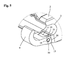
旋回が可能で折り込み可能な構成のおかげで、捕獲フック9は、図5及び図6に示す始動位置(開始位置)と、図7及び図8に示す折り込み位置との間で可動である。例えば、迅速交換装置1を操作する操作員が、捕獲フックを迂回させたり、再配置するために、地上の掘削機を支持するつもりで、捕獲フック9を障害物に衝突させたり、不適切な操作でそれを使用した場合にも捕獲フック9は折り込みが可能であり、低減された力が支持部2との接続部に作用し、支持部への影響を可能な限り少なくする。さらに、捕獲フック9への損傷が発生した場合には、フックを必要に応じて容易に交換できる。
Thanks to its pivotable and foldable configuration, the
図5から図8で示すように、捕獲フック9は、脚部14の後方端に、支持部2の方向に面した上方の曲面部19と、支持部2の前方の停止面21に当接するための後方の当接面20とを有する。下方の始動位置において捕獲フック9の後方の当接面20は支持部2の停止面21に当接し、捕獲フック9はこの捕獲位置にてその場に保持される。もし相当な力が下方から作用すれば、曲面部19のために、捕獲フック9は横断軸10の周りで回転(回動)でき、上方の折り込み位置にまで移動できる。下方の始動位置と上方の折り込み位置の両方で、収容部3は捕獲フック9によって前方に向かって閉じられ、アタッチメントは確実に捕獲され、ロック機構が意図に反して解除されたとしてもその場に保持される。捕獲フック9は重力によって、あるいは戻りバネ(図示せず)によって折り込み位置から始動位置にまで戻ることができる。
5 to 8, the
図9から図11は、本発明に従う、捕獲装置8を有した迅速交換装置1の第2の実施例を示す。繰り返すが、この実施例においても、捕獲装置8は、迅速交換装置1の支持部2に非固定式であり旋回式に取り付けられている2つの別々の捕獲フック9を有する。また、これら2つの捕獲フック9は支持部2のブリッジ形態結合部材11に蝶番付け(ヒンジ連結)されており、横断軸10の周りを旋回することができる。このため、ブリッジ形態結合部材11は横断腔部12を有しており、捕獲フック9は横断軸10を受領するための相補的な受領腔部15を有する。
Figures 9 to 11 show a second embodiment of a
図10及び図11に示すように、支持部2の方向に面している後方側で、捕獲フック9は、上方内面23と下方内面24を備えた凹部22をそれぞれ有する。捕獲フック9の凹部22は、ここではブロック形態であるブリッジ形態結合部材11よりも少々大きく、ブリッジ形態結合部材11と、凹部22の上方内面23及び下方内面24のそれぞれの間に、上方間隙25と下方間隙26がそれぞれ形成されている。ゴム製または他の弾性材料製である緩衝要素27が上方間隙25と下方間隙26のそれぞれの中に挿入される。この実施例においても、捕獲フック9は支持部2に対して旋回できる。しかし、この実施例では、旋回および折り込みの動作は、間隙25と間隙26のサイズ、及び緩衝要素27の反動後退性の程度によって制限されている。しかしながら、第1の実施例とは異なり、捕獲フック9は、捕獲フックが変形することなく上方ばかりか下方にも移動できる。よって、捕獲フック9は支持部2に反動後退性を伴って蝶番付け(ヒンジ連結)されており、上方と下方の両方向に動ける。
10 and 11, on the rear side facing towards the
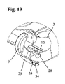
図12から図15は、本発明に従う、捕獲装置8を有した迅速交換装置1の第3の実施例を示す。この実施例でも、捕獲装置8は、迅速交換装置1の支持部2に非固定式であり旋回可能に取り付けられた2つの別々の捕獲フック9を含んでいる。また、この実施例でも、これら2つの捕獲フック9は支持部2のブリッジ形態結合部材11に蝶番付け(ヒンジ連結)されており、横断軸10の周りを旋回することができる。但しこの実施例では、横断軸10は、相補的な横断腔部や受領腔部に挿入された別々なボルトやピンではなく、捕獲フック9と一体的に形成された軸受ジャーナルであり、そのおかげで、捕獲フック9はブリッジ形態結合部材11で半殻の収容部28内に配置され、相補部品29によって下方からその場に保持される。
Figures 12 to 15 show a third embodiment of a
図14に示すように、軸受ジャーナルの形態である2つの横方向に延び出る横断軸10は、捕獲フック9上にて側方削耗域30により形成されている。その底面において、捕獲フックは、2つの強力バネピン33と34のための横断腔部32(複数)を備えたブリッジ形態部材31を有しており、それらによって捕獲フック9をブリッジ形態結合部材11上でその場に保持するための相補部品29が取り付けられている。この相補部品29は、捕獲フック9が軸受(半)殻状の収容部28から、その横断軸10と共に上方にスライドするのを防止する。
As shown in FIG. 14, two laterally extending
図15には、図12に示す実施例のブリッジ形態結合部材11が、相互に距離を隔てて配置された2つの平行な脚部35を有することが示されている。横断軸10を旋回可能に取り付けるための半殻の収容部28が、2つの脚部35の上部面に配置され、中間空部36によって離間されている。2つの横断方向に延び出る横断軸10を具備しつつ中間空部36内に突き出す捕獲フック9は、収容部28内に挿入されると共に、相補部品29によってその場に固定される。
FIG. 15 shows that the bridge-shaped
同様に、図12から図15に示す実施例においては、捕獲フック9はその接続位置から意図に反して解放されたアタッチメントを捕獲位置にて捕獲でき、よって迅速交換装置のその場に確実に保持できる。
Similarly, in the embodiment shown in FIGS. 12 to 15, the
1.迅速交換装置
2.支持部
3.第1の収容部(受領部)
4.第2の収容部(受領部)
5.当接面
6.横側部
7.受領開口部
8.捕獲装置
9.捕獲フック
10.横断軸
11.ブリッジ形態結合部材
12.横断腔部
13.中間空部
14.脚部
15.受領腔部
16.ピン
17.軸受面
18.軸受スリーブ
19.曲面部
20.当接面
21.停止面
22.凹部
23.上方内面
24.下方内面
25.上方間隙
26.下方間隙
27.緩衝要素
28.半殻の収容部(受領部)
29.相補部品
30.削耗域
31.ブリッジ形態部材
32.横断腔部
33.強力バネピン
34.強力バネピン
35.脚部
36.中間空部
1. quick change device2.
4. Second Containment Section (Receiving Section)
5.
29.
Claims (14)
前記ロック装置は、後退した解放位置と、延び出たロック位置との間を移動可能な複数のボルト形状のロック要素を有しており、
前記アタッチメントが、前記ロック要素の解放位置への意図しない動作を生じさせる操作員の操作間違いの結果として脱落するのを防止するために、前記捕獲装置(8)が、前記支持部(2)に旋回可能に配設された少なくとも1つの捕獲フック(9)を有している、ことを特徴とする迅速交換装置。 A quick change device (1) for changing an attachment of a construction machine, comprising a support (2) and arranged on one side of said support (2) for receiving a first connecting element. a first receptacle (3) arranged on the other side of said support (2) for receiving a second connection element; A quick change device comprising a locking device for detachably retaining a connecting element in place and a catch device (8) arranged on said support (2) for capturing said attachment. in
said locking device comprising a plurality of bolt-shaped locking elements movable between a retracted release position and an extended locking position;
In order to prevent the attachment from falling out as a result of operator error resulting in unintended movement of the locking element into the release position, the catch device (8) is attached to the support (2). A quick change device, characterized in that it has at least one catch hook (9) which is pivotally arranged.
Applications Claiming Priority (5)
| Application Number | Priority Date | Filing Date | Title |
|---|---|---|---|
| DE102018105049.6 | 2018-03-06 | ||
| DE102018105049.6A DE102018105049A1 (en) | 2018-03-06 | 2018-03-06 | Quick coupler |
| EP18207938.4 | 2018-11-23 | ||
| EP18207938.4A EP3536861B1 (en) | 2018-03-06 | 2018-11-23 | Quick changer |
| PCT/EP2019/055374 WO2019170629A1 (en) | 2018-03-06 | 2019-03-05 | Quick-change device |
Publications (2)
| Publication Number | Publication Date |
|---|---|
| JP2021510399A JP2021510399A (en) | 2021-04-22 |
| JP7162359B2 true JP7162359B2 (en) | 2022-10-28 |
Family
ID=64456785
Family Applications (1)
| Application Number | Title | Priority Date | Filing Date |
|---|---|---|---|
| JP2020524337A Active JP7162359B2 (en) | 2018-03-06 | 2019-03-05 | quick change device |
Country Status (12)
| Country | Link |
|---|---|
| US (1) | US11976435B2 (en) |
| EP (1) | EP3536861B1 (en) |
| JP (1) | JP7162359B2 (en) |
| AU (1) | AU2019229524B2 (en) |
| CA (1) | CA3081804C (en) |
| DE (1) | DE102018105049A1 (en) |
| DK (1) | DK3536861T3 (en) |
| ES (1) | ES2959286T3 (en) |
| FI (1) | FI3536861T3 (en) |
| HU (1) | HUE063693T2 (en) |
| PL (1) | PL3536861T3 (en) |
| WO (1) | WO2019170629A1 (en) |
Families Citing this family (1)
| Publication number | Priority date | Publication date | Assignee | Title |
|---|---|---|---|---|
| DE102022117974A1 (en) | 2022-07-19 | 2024-01-25 | OilQuick Deutschland KG | QUICK CHANGE AND QUICK CHANGE SYSTEM WITH SUCH A QUICK CHANGE |
Citations (3)
| Publication number | Priority date | Publication date | Assignee | Title |
|---|---|---|---|---|
| JP2000008402A (en) | 1998-06-26 | 2000-01-11 | Marujun Juko Kk | Quick coupler |
| JP2002524673A (en) | 1998-09-08 | 2002-08-06 | ミラー、ドーリーン、ジャックリーヌ | Quick coupler for bucket excavator |
| WO2015199081A1 (en) | 2014-06-26 | 2015-12-30 | 株式会社小松製作所 | Quick coupler |
Family Cites Families (29)
| Publication number | Priority date | Publication date | Assignee | Title |
|---|---|---|---|---|
| DE2249268A1 (en) * | 1972-10-07 | 1974-04-11 | Ley Maschf W | LEVELING DEVICE FOR HANGING IN THE FRONT AND REAR LOADER ARMS WITH HYDRAULICALLY SWIVELING LOADING SHOVEL |
| DE3538156C1 (en) * | 1985-10-26 | 1986-07-24 | Hoesch Ag, 4600 Dortmund | Excavator tooth |
| JP3677905B2 (en) * | 1996-11-14 | 2005-08-03 | 株式会社小松製作所 | Construction machine work equipment attachment / detachment device |
| US5974706A (en) | 1997-03-10 | 1999-11-02 | Clark Equipment Company | Attachment construction for earthworking implement |
| IE981051A1 (en) * | 1997-12-16 | 1999-06-16 | Redrock Engineering Ltd | Attachement device for excavating or digging apparatus |
| US6301811B1 (en) * | 2000-07-28 | 2001-10-16 | Gilmore Industries, Inc. | Coupler for a heavy-duty machine |
| JP4111333B2 (en) * | 2003-12-15 | 2008-07-02 | 日立建機株式会社 | Suspended attachment attachment / detachment device and handling machine |
| GB2433246B (en) * | 2005-12-13 | 2010-01-20 | Tower Street Technologies Ltd | Coupler with improved jaw configuration |
| US7984576B2 (en) * | 2006-09-04 | 2011-07-26 | Miller Uk Limited | Coupler |
| CA2686622C (en) * | 2008-03-07 | 2016-06-28 | Wedgelock Equipment Limited | Coupler for earth moving or materials handling machine |
| ITMO20080143A1 (en) * | 2008-05-15 | 2009-11-16 | Mantovanibenne S R L | ATTACHMENT ORGAN FOR THE CONNECTION OF A TOOL WITH AN OPERATOR ARM WITH SAFETY LOCK. |
| EP2159334B1 (en) * | 2008-08-29 | 2016-11-23 | Riedlberger GmbH | Coupling device |
| CH700307A1 (en) * | 2009-01-23 | 2010-07-30 | Josef Martin Gmbh & Co Kg | Quick-coupler for e.g. excavator, has blocking element moved from one position to another position where clearance of opening is reduced by element and vice versa, where element is adjusted parallel to shifting direction of grip arms |
| EP2470724B1 (en) * | 2009-09-22 | 2014-03-26 | Ian Hill | Hydraulic coupler with pin retention system for coupling an attachment to a work machine |
| GB2474905B (en) * | 2009-11-02 | 2015-07-22 | Patrick Mccormick | A quick hitch coupler |
| KR101811461B1 (en) * | 2009-12-09 | 2017-12-21 | 에스 티 커플러스 리미티드 | Improvements relating to couplers |
| US8585345B2 (en) * | 2010-03-26 | 2013-11-19 | Paladin Brands Group, Inc. | Coupler with pivoting front hook lock |
| SE536061C2 (en) | 2011-09-15 | 2013-04-23 | Steelwrist Ab | Front axle locking for attachment |
| DE202013004797U1 (en) * | 2013-05-23 | 2014-08-25 | Kinshofer Gmbh | Quick coupler |
| KR101542226B1 (en) * | 2013-10-30 | 2015-08-07 | 강토중공업(주) | Safety locking device for quick coupler |
| KR101628984B1 (en) * | 2014-08-06 | 2016-06-10 | 강토중공업(주) | Locking device for quick coupler |
| JP2016166509A (en) * | 2015-03-10 | 2016-09-15 | ヤンマー株式会社 | Attachment connection device |
| CA2980700C (en) * | 2015-03-25 | 2023-09-19 | Wedgelock Equipment Limited | An indicator |
| DE102015225498A1 (en) * | 2015-12-16 | 2017-06-22 | Oilquick Deutschland Gmbh | QUICK CHANGE SYSTEM WITH MECHANICAL SAFETY DEVICE FOR UNINTENDED DISSOLUTION OF A WORK EQUIPMENT |
| EP3538156A1 (en) | 2016-11-10 | 2019-09-18 | Regents of the University of Minnesota | Surfactants and methods for making same |
| GB2576486B (en) * | 2018-06-25 | 2023-05-10 | Miller Uk Ltd | Coupler |
| GB2576131B (en) * | 2018-06-25 | 2023-01-18 | Miller Uk Ltd | Coupler |
| GB2612533B (en) * | 2018-06-25 | 2023-11-22 | Miller Uk Ltd | Coupler |
| DE102018128479A1 (en) * | 2018-11-14 | 2020-05-14 | Oilquick Deutschland Gmbh | Quick hitch and quick hitch system with such a quick hitch |
-
2018
- 2018-03-06 DE DE102018105049.6A patent/DE102018105049A1/en active Pending
- 2018-11-23 PL PL18207938.4T patent/PL3536861T3/en unknown
- 2018-11-23 EP EP18207938.4A patent/EP3536861B1/en active Active
- 2018-11-23 ES ES18207938T patent/ES2959286T3/en active Active
- 2018-11-23 FI FIEP18207938.4T patent/FI3536861T3/en active
- 2018-11-23 DK DK18207938.4T patent/DK3536861T3/en active
- 2018-11-23 HU HUE18207938A patent/HUE063693T2/en unknown
-
2019
- 2019-03-05 CA CA3081804A patent/CA3081804C/en active Active
- 2019-03-05 WO PCT/EP2019/055374 patent/WO2019170629A1/en active Application Filing
- 2019-03-05 JP JP2020524337A patent/JP7162359B2/en active Active
- 2019-03-05 AU AU2019229524A patent/AU2019229524B2/en active Active
-
2020
- 2020-09-03 US US17/010,908 patent/US11976435B2/en active Active
Patent Citations (3)
| Publication number | Priority date | Publication date | Assignee | Title |
|---|---|---|---|---|
| JP2000008402A (en) | 1998-06-26 | 2000-01-11 | Marujun Juko Kk | Quick coupler |
| JP2002524673A (en) | 1998-09-08 | 2002-08-06 | ミラー、ドーリーン、ジャックリーヌ | Quick coupler for bucket excavator |
| WO2015199081A1 (en) | 2014-06-26 | 2015-12-30 | 株式会社小松製作所 | Quick coupler |
Also Published As
| Publication number | Publication date |
|---|---|
| CA3081804A1 (en) | 2019-09-12 |
| FI3536861T3 (en) | 2023-09-21 |
| EP3536861B1 (en) | 2023-08-09 |
| US20200399853A1 (en) | 2020-12-24 |
| CA3081804C (en) | 2022-09-27 |
| HUE063693T2 (en) | 2024-02-28 |
| AU2019229524A1 (en) | 2020-07-16 |
| ES2959286T3 (en) | 2024-02-22 |
| AU2019229524B2 (en) | 2020-12-24 |
| DE102018105049A1 (en) | 2019-09-12 |
| PL3536861T3 (en) | 2023-10-02 |
| JP2021510399A (en) | 2021-04-22 |
| DK3536861T3 (en) | 2023-09-11 |
| EP3536861A1 (en) | 2019-09-11 |
| US11976435B2 (en) | 2024-05-07 |
| WO2019170629A1 (en) | 2019-09-12 |
Similar Documents
| Publication | Publication Date | Title |
|---|---|---|
| FI3653796T3 (en) | Quick changer and quick change system comprising such a quick changer | |
| US8262310B2 (en) | Coupler with secondary lock on front hook | |
| US6922926B2 (en) | Universal coupler for excavator buckets | |
| JP5150724B2 (en) | Quick coupler assembly for connecting an instrument to a machine arm | |
| US4397604A (en) | Releasable bucket and other tool connection for backhoe | |
| US20140215866A1 (en) | Thumb with detachable body | |
| JP7481020B2 (en) | coupler | |
| US6139212A (en) | Coupler for excavating machines and the like having fixed and moveable jaws | |
| JP7162359B2 (en) | quick change device | |
| WO2011048413A1 (en) | A coupler for coupling an attachment to a machine | |
| JPH07500155A (en) | Drive machine with articulated boom | |
| AU2012201264B2 (en) | A safety mechanism for a coupler for coupling an accessory to a dipper arm | |
| KR20220002803U (en) | Coupler for excavator | |
| WO2012013952A1 (en) | A coupler for coupling an attachment to a machine | |
| FI3502357T3 (en) | Quick changer | |
| JP2024013214A (en) | Quick coupler, and quick coupler system with such quick coupler | |
| SK289098B6 (en) | Clamping mechanism for tools of soil-shifting machines | |
| CA3231938A1 (en) | A coupler | |
| IE20130069U1 (en) | A safety mechanism for a coupler for coupling an accessory to a dipper arm | |
| IES86256Y1 (en) | A safety mechanism for a coupler for coupling an accessory to a dipper arm |
Legal Events
| Date | Code | Title | Description |
|---|---|---|---|
| A521 | Request for written amendment filed |
Free format text: JAPANESE INTERMEDIATE CODE: A523 Effective date: 20200713 |
|
| A621 | Written request for application examination |
Free format text: JAPANESE INTERMEDIATE CODE: A621 Effective date: 20200713 |
|
| A131 | Notification of reasons for refusal |
Free format text: JAPANESE INTERMEDIATE CODE: A131 Effective date: 20210810 |
|
| A131 | Notification of reasons for refusal |
Free format text: JAPANESE INTERMEDIATE CODE: A131 Effective date: 20220315 |
|
| A521 | Request for written amendment filed |
Free format text: JAPANESE INTERMEDIATE CODE: A523 Effective date: 20220525 |
|
| TRDD | Decision of grant or rejection written | ||
| A01 | Written decision to grant a patent or to grant a registration (utility model) |
Free format text: JAPANESE INTERMEDIATE CODE: A01 Effective date: 20220920 |
|
| A61 | First payment of annual fees (during grant procedure) |
Free format text: JAPANESE INTERMEDIATE CODE: A61 Effective date: 20221011 |
|
| R150 | Certificate of patent or registration of utility model |
Ref document number: 7162359 Country of ref document: JP Free format text: JAPANESE INTERMEDIATE CODE: R150 |