JP7158397B2 - 自己調整型ハイブリッド誘導/永久磁石ロータを備えたハイブリッド誘導モータ - Google Patents
自己調整型ハイブリッド誘導/永久磁石ロータを備えたハイブリッド誘導モータ Download PDFInfo
- Publication number
- JP7158397B2 JP7158397B2 JP2019544851A JP2019544851A JP7158397B2 JP 7158397 B2 JP7158397 B2 JP 7158397B2 JP 2019544851 A JP2019544851 A JP 2019544851A JP 2019544851 A JP2019544851 A JP 2019544851A JP 7158397 B2 JP7158397 B2 JP 7158397B2
- Authority
- JP
- Japan
- Prior art keywords
- squirrel cage
- rotor
- motor
- bars
- cage bars
- Prior art date
- Legal status (The legal status is an assumption and is not a legal conclusion. Google has not performed a legal analysis and makes no representation as to the accuracy of the status listed.)
- Active
Links
- 230000006698 induction Effects 0.000 title description 33
- 241000555745 Sciuridae Species 0.000 claims description 78
- 230000001360 synchronised effect Effects 0.000 claims description 31
- 230000004907 flux Effects 0.000 claims description 22
- 230000004888 barrier function Effects 0.000 claims description 15
- 230000001939 inductive effect Effects 0.000 claims description 15
- 230000008878 coupling Effects 0.000 claims description 8
- 238000010168 coupling process Methods 0.000 claims description 8
- 238000005859 coupling reaction Methods 0.000 claims description 8
- 239000000463 material Substances 0.000 description 11
- RYGMFSIKBFXOCR-UHFFFAOYSA-N Copper Chemical compound [Cu] RYGMFSIKBFXOCR-UHFFFAOYSA-N 0.000 description 10
- 229910052802 copper Inorganic materials 0.000 description 10
- 239000010949 copper Substances 0.000 description 10
- 238000000034 method Methods 0.000 description 7
- 239000004020 conductor Substances 0.000 description 5
- 238000004804 winding Methods 0.000 description 5
- CWYNVVGOOAEACU-UHFFFAOYSA-N Fe2+ Chemical compound [Fe+2] CWYNVVGOOAEACU-UHFFFAOYSA-N 0.000 description 4
- 230000000694 effects Effects 0.000 description 4
- XAGFODPZIPBFFR-UHFFFAOYSA-N aluminium Chemical compound [Al] XAGFODPZIPBFFR-UHFFFAOYSA-N 0.000 description 3
- 229910052782 aluminium Inorganic materials 0.000 description 3
- XEEYBQQBJWHFJM-UHFFFAOYSA-N Iron Chemical compound [Fe] XEEYBQQBJWHFJM-UHFFFAOYSA-N 0.000 description 2
- 229910000831 Steel Inorganic materials 0.000 description 2
- 230000001133 acceleration Effects 0.000 description 2
- 239000010941 cobalt Substances 0.000 description 2
- 229910017052 cobalt Inorganic materials 0.000 description 2
- GUTLYIVDDKVIGB-UHFFFAOYSA-N cobalt atom Chemical compound [Co] GUTLYIVDDKVIGB-UHFFFAOYSA-N 0.000 description 2
- 239000002131 composite material Substances 0.000 description 2
- 238000003475 lamination Methods 0.000 description 2
- 239000003562 lightweight material Substances 0.000 description 2
- 229910052709 silver Inorganic materials 0.000 description 2
- 239000004332 silver Substances 0.000 description 2
- 229910001220 stainless steel Inorganic materials 0.000 description 2
- 239000010959 steel Substances 0.000 description 2
- 239000011800 void material Substances 0.000 description 2
- 229910000906 Bronze Inorganic materials 0.000 description 1
- 241000699800 Cricetinae Species 0.000 description 1
- 229920000271 Kevlar® Polymers 0.000 description 1
- 229910000596 Oilite Inorganic materials 0.000 description 1
- 230000004913 activation Effects 0.000 description 1
- 238000013459 approach Methods 0.000 description 1
- 239000010974 bronze Substances 0.000 description 1
- 230000008859 change Effects 0.000 description 1
- KUNSUQLRTQLHQQ-UHFFFAOYSA-N copper tin Chemical compound [Cu].[Sn] KUNSUQLRTQLHQQ-UHFFFAOYSA-N 0.000 description 1
- 230000005674 electromagnetic induction Effects 0.000 description 1
- 229910052742 iron Inorganic materials 0.000 description 1
- 238000012986 modification Methods 0.000 description 1
- 230000004048 modification Effects 0.000 description 1
- 229910001172 neodymium magnet Inorganic materials 0.000 description 1
- 229910052761 rare earth metal Inorganic materials 0.000 description 1
- 150000002910 rare earth metals Chemical class 0.000 description 1
- 238000009987 spinning Methods 0.000 description 1
Images


Classifications
-
- H—ELECTRICITY
- H02—GENERATION; CONVERSION OR DISTRIBUTION OF ELECTRIC POWER
- H02K—DYNAMO-ELECTRIC MACHINES
- H02K17/00—Asynchronous induction motors; Asynchronous induction generators
- H02K17/02—Asynchronous induction motors
- H02K17/26—Asynchronous induction motors having rotors or stators designed to permit synchronous operation
-
- H—ELECTRICITY
- H02—GENERATION; CONVERSION OR DISTRIBUTION OF ELECTRIC POWER
- H02K—DYNAMO-ELECTRIC MACHINES
- H02K1/00—Details of the magnetic circuit
- H02K1/06—Details of the magnetic circuit characterised by the shape, form or construction
- H02K1/12—Stationary parts of the magnetic circuit
- H02K1/14—Stator cores with salient poles
- H02K1/146—Stator cores with salient poles consisting of a generally annular yoke with salient poles
-
- H—ELECTRICITY
- H02—GENERATION; CONVERSION OR DISTRIBUTION OF ELECTRIC POWER
- H02K—DYNAMO-ELECTRIC MACHINES
- H02K1/00—Details of the magnetic circuit
- H02K1/06—Details of the magnetic circuit characterised by the shape, form or construction
- H02K1/22—Rotating parts of the magnetic circuit
- H02K1/223—Rotor cores with windings and permanent magnets
-
- H—ELECTRICITY
- H02—GENERATION; CONVERSION OR DISTRIBUTION OF ELECTRIC POWER
- H02K—DYNAMO-ELECTRIC MACHINES
- H02K1/00—Details of the magnetic circuit
- H02K1/06—Details of the magnetic circuit characterised by the shape, form or construction
- H02K1/22—Rotating parts of the magnetic circuit
- H02K1/24—Rotor cores with salient poles ; Variable reluctance rotors
- H02K1/246—Variable reluctance rotors
-
- H—ELECTRICITY
- H02—GENERATION; CONVERSION OR DISTRIBUTION OF ELECTRIC POWER
- H02K—DYNAMO-ELECTRIC MACHINES
- H02K16/00—Machines with more than one rotor or stator
- H02K16/02—Machines with one stator and two or more rotors
-
- H—ELECTRICITY
- H02—GENERATION; CONVERSION OR DISTRIBUTION OF ELECTRIC POWER
- H02K—DYNAMO-ELECTRIC MACHINES
- H02K17/00—Asynchronous induction motors; Asynchronous induction generators
- H02K17/02—Asynchronous induction motors
- H02K17/16—Asynchronous induction motors having rotors with internally short-circuited windings, e.g. cage rotors
- H02K17/165—Asynchronous induction motors having rotors with internally short-circuited windings, e.g. cage rotors characterised by the squirrel-cage or other short-circuited windings
-
- H—ELECTRICITY
- H02—GENERATION; CONVERSION OR DISTRIBUTION OF ELECTRIC POWER
- H02K—DYNAMO-ELECTRIC MACHINES
- H02K17/00—Asynchronous induction motors; Asynchronous induction generators
- H02K17/02—Asynchronous induction motors
- H02K17/16—Asynchronous induction motors having rotors with internally short-circuited windings, e.g. cage rotors
- H02K17/20—Asynchronous induction motors having rotors with internally short-circuited windings, e.g. cage rotors having deep-bar rotors
-
- H—ELECTRICITY
- H02—GENERATION; CONVERSION OR DISTRIBUTION OF ELECTRIC POWER
- H02K—DYNAMO-ELECTRIC MACHINES
- H02K19/00—Synchronous motors or generators
- H02K19/02—Synchronous motors
- H02K19/10—Synchronous motors for multi-phase current
- H02K19/103—Motors having windings on the stator and a variable reluctance soft-iron rotor without windings
-
- H—ELECTRICITY
- H02—GENERATION; CONVERSION OR DISTRIBUTION OF ELECTRIC POWER
- H02K—DYNAMO-ELECTRIC MACHINES
- H02K19/00—Synchronous motors or generators
- H02K19/02—Synchronous motors
- H02K19/14—Synchronous motors having additional short-circuited windings for starting as asynchronous motors
-
- H—ELECTRICITY
- H02—GENERATION; CONVERSION OR DISTRIBUTION OF ELECTRIC POWER
- H02K—DYNAMO-ELECTRIC MACHINES
- H02K21/00—Synchronous motors having permanent magnets; Synchronous generators having permanent magnets
- H02K21/46—Motors having additional short-circuited winding for starting as an asynchronous motor
-
- H—ELECTRICITY
- H02—GENERATION; CONVERSION OR DISTRIBUTION OF ELECTRIC POWER
- H02K—DYNAMO-ELECTRIC MACHINES
- H02K5/00—Casings; Enclosures; Supports
- H02K5/04—Casings or enclosures characterised by the shape, form or construction thereof
- H02K5/16—Means for supporting bearings, e.g. insulating supports or means for fitting bearings in the bearing-shields
- H02K5/173—Means for supporting bearings, e.g. insulating supports or means for fitting bearings in the bearing-shields using bearings with rolling contact, e.g. ball bearings
- H02K5/1732—Means for supporting bearings, e.g. insulating supports or means for fitting bearings in the bearing-shields using bearings with rolling contact, e.g. ball bearings radially supporting the rotary shaft at both ends of the rotor
Landscapes
- Engineering & Computer Science (AREA)
- Power Engineering (AREA)
- Permanent Magnet Type Synchronous Machine (AREA)
- Permanent Field Magnets Of Synchronous Machinery (AREA)
- Reciprocating, Oscillating Or Vibrating Motors (AREA)
- Induction Machinery (AREA)
- Iron Core Of Rotating Electric Machines (AREA)
Description
Claims (17)
- ハイブリッドリスかご型ケージ式及び永久磁石式のモータであって、
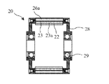
モータハウジングと、
前記モータハウジングに固定されて回転ステータ磁界を生成するステータと、
前記モータハウジングに回転可能に接続されて、前記モータハウジングの少なくとも1つの連結用端部から負荷まで延びたモータシャフトと、
前記モータシャフトに回転式に固定されかつ前記モータシャフトと同軸上に設けられる第2ロータと、
前記ステータと前記第2ロータとの間に、かつ前記モータシャフトと同軸上に設けられ、前記モータシャフトに回転可能に機械的結合せず前記モータシャフトと共に回転しない第1ロータと、
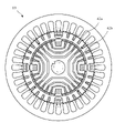
を備え、前記第2ロータは、
第2ロータコアと、
前記第2ロータコアに埋め込まれた複数の第2リスかご型ケージバーであって、導電性で、互いに周方向に間隔を空けて設けられた複数の第2リスかご型ケージバーと、
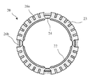
を備え、前記第1ロータは、
第1ロータコアと、
起動時に回転ステータ磁界と協働してトルクを生成するように構成された少なくとも1つの誘導素子と、
前記少なくとも1つの誘導素子から前記第2ロータの方に径方向に離間して配される永久磁石であって、前記少なくとも1つの誘導素子と、周方向におけるある角度で、径方向に重なる永久磁石と、
を備え、前記少なくとも1つの誘導素子は前記永久磁石と前記ステータとの径方向の間に位置し、
前記第1ロータと前記第2ロータは同期動作中磁気的に結合可能である、
モータ。 - 前記第2ロータコア内に複数の磁束バリアを含み、前記磁束バリアは同期動作の間に前記第2ロータコアを通して前記回転ステータ磁界をガイドし、前記磁束バリアは前記第2ロータコア内のボイドである、請求項1に記載のモータ。
- 前記第2ロータコア内に複数の磁束バリアを含み、前記磁束バリアは同期動作の間に前記第2ロータコアを通して前記回転ステータ磁界をガイドし、前記磁束バリアは、前記第2リスかご型ケージバーの内端同士を接続する凹型経路である、請求項1に記載のモータ。
- 前記少なくとも1つの誘導素子は、前記第1ロータコアの前記ステータに向いた面に埋め込まれた複数の周方向に間隔を空けて設けられた導電性の第1リスかご型ケージバーを有する、請求項1に記載のモータ。
- 前記少なくとも1つの誘導素子は、周方向に間隔を空けて設けられた複数の第1小リスかご型ケージバーを有し、前記複数の第1小リスかご型ケージバーはN個の第1グループに分割され、前記第1グループのそれぞれは、連続した複数の前記第1小リスかご型ケージバーを含み、
前記第1のグループは、周方向に間隔を空けて設けられたN個の第1大リスかご型ケージバーによって周方向に分離され、前記第1大リスかご型ケージバーは、連続する前記第1グループを分離する、
請求項1に記載のモータ。 - 前記複数の第2リスかご型ケージバーは、前記第2ロータコアの第2外面内に周方向に間隔を空けて埋め込まれる、請求項5に記載のモータ。
- 前記少なくとも1つの誘導素子は、前記ステータに面する前記第1ロータに渦電流リングを有する、請求項2に記載のモータ。
- 前記ステータは、前記第1ロータ及び前記第2ロータの外側に位置し、
前記第2ロータはインナーロータであり、
前記第1ロータは、前記インナーロータと前記ステータの間に位置するアウターロータである、
請求項1に記載のモータ。 - 前記少なくとも1つの誘導素子は複数の第1リスかご型ケージバーを含み、
同期速度において、
・ 前記複数の第1リスかご型ケージバーは前記複数の第2リスかご型ケージバーに角度的に位置が合い、
・ 前記ステータから、前記複数の第1リスかご型ケージバーの間を通り、前記永久磁石を通って、前記複数の第2リスかご型ケージバーの間へと磁力線が通過する、
請求項8に記載のモータ。 - 前記永久磁石はN個の周方向に間隔を空けて設けられた永久磁石を含み、
前記少なくとも1つの誘導素子は、前記第1ロータコアに埋め込まれた導電性の複数の第1小リスかご型ケージバーからなる第1グループをN個含み、前記N個の第1グループはそれぞれ、前記N個の永久磁石のうちの1つと角度的に位置が合っており、
前記少なくとも1つの誘導素子は更に、前記第1ロータコアの埋め込まれた導電性の第1大リスかご型ケージバーをN個含み、前記第1大リスかご型ケージバーはいずれも、前記第1小リスかご型ケージバーのどれよりも大きな断面を有し、前記第1大リスかご型ケージバーは、前記N個の永久磁石の間の間隙に角度的に位置が合っており、
前記N個の第1大リスかご型ケージバーはそれぞれ、前記N個の第1グループを周方向に分離している、
請求項1に記載のモータ。 - 前記第2リスかご型ケージバーは、複数の第2小リスかご型ケージバーからなるグループをN個と、第2大リスかご型ケージバーをN個含み、
同期動作の間、前記第2小リスかご型ケージバーは、個々に前記第1小リスかご型ケージバーと位置が合い、前記第2大リスかご型ケージバーは、個々に前記第1大リスかご型ケージバーと位置が合う、
請求項10に記載のモータ。 - 前記少なくとも1つの誘導素子は複数の第1リスかご型ケージバーを含み、
同期動作の間、前記複数の第2リスかご型ケージバーの各々は、前記複数の第1リスかご型ケージバーのいずれかと位置が合う、
請求項1に記載のモータ。 - 前記永久磁石はN個の周方向に間隔を空けて設けられた永久磁石を含み、
前記N個の第1グループのそれぞれは、前記N個の永久磁石のいずれかに径方向に重なって位置する、
請求項5に記載のモータ。 - ハイブリッドリスかご型ケージ式及び永久磁石式のモータであって、
モータハウジングと、
前記モータハウジングに固定されて回転ステータ磁界を生成するステータと、
前記モータハウジングに回転可能に接続されて、前記モータハウジングの少なくとも1つの連結用端部から負荷まで延びたモータシャフトと、
前記モータシャフトに回転式に固定されかつ前記モータシャフトと同軸上に設けられる第2ロータと、
前記ステータと前記第2ロータとの間に、かつ前記モータシャフトと同軸上に設けられ、前記モータシャフトに回転可能に機械的結合せず如何なる動作中も前記モータシャフトと共に回転しない第1ロータとを備え、
を備え、前記第2ロータは、
第2ロータコアと、
前記第2ロータコアに埋め込まれた複数の第2リスかご型ケージバーであって、導電性で、互いに周方向に間隔を空けて設けられた複数の第2リスかご型ケージバーと、
を備え、前記第1ロータは、
第1ロータコアと、
前記第1ロータコアに埋め込まれた複数の第1リスかご型ケージバーであって、導電性で、互いに周方向に間隔を空けて設けられた複数の第1リスかご型ケージバーと、
前記第1ロータコア内に位置する複数の永久磁石であって、前記複数の第1リスかご型ケージバーから前記第2ロータの方に径方向に離れて位置し、前記複数の第1リスかご型ケージバーに、周方向におけるある角度で、径方向に重なる複数の永久磁石と、
を備え、
前記複数の第1リスかご型ケージバーは回転ステータ磁場と協働して始動時のトルクを提供するように構成され、同期動作の間、前記複数の第1リスかご型ケージバーは前記複数の第2リスかご型ケージバーに同時に角度的に位置が合うことができ、
前記複数の第1リスかご型ケージバーは前記複数の永久磁石と前記ステータの径方向の間に位置する、
モータ。 - 請求項14に記載のモータであって、
前記永久磁石はN個の永久磁石からなり、
前記第1リスかご型ケージバーは複数の第1小リスかご型ケージバーを有し、前記複数の第1小リスかご型ケージバーはN個の第1グループに分割され、前記第1グループのそれぞれは、連続した前記第1小リスかご型ケージバーを複数含み、
前記第1リスかご型ケージバーの前記第1グループのそれぞれは、前記N個の永久磁石のいずれかに径方向に重なって位置する、
モータ。 - ハイブリッドリスかご型ケージ式及び永久磁石式のモータであって、
モータハウジングと、
前記モータハウジングに固定されて回転ステータ磁界を生成するステータと、
前記モータハウジングに回転可能に接続されて、前記モータハウジングの少なくとも1つの連結用端部から負荷まで延びたモータシャフトと、
前記モータシャフトに回転式に固定されかつ前記モータシャフトと同軸上に設けられる第2ロータと、
前記ステータと前記第2ロータとの間に、かつ前記モータシャフトと同軸上に設けられ、前記モータシャフトに回転可能に機械的結合せず前記モータシャフトと共に回転しない第1ロータと、
を備え、前記第2ロータは、
第2ロータコアと、
前記第2ロータコアに埋め込まれた複数の第2リスかご型ケージバーであって、導電性で、互いに周方向に間隔を空けて設けられた複数の第2リスかご型ケージバーと、
を備え、前記第1ロータは、
第1ロータコアと、
前記第1ロータコアに埋め込まれた複数の第1リスかご型ケージバーであって、導電性で互いに周方向に間隔を空けて設けられし、回転ステータ磁場と協働して始動時のトルクを提供するように構成される、第1リスかご型ケージバーと、
前記第1リスかご型ケージバーの下で、前記第2ロータに向いた前記第1ロータコアの面の上に位置する永久磁石と、
を備え、同期動作の間、ステータ磁力線は、前記複数の第1リスかご型ケージバーのうちの連続する前記第1リスかご型ケージバーの間、及び、前記複数の第2リスかご型ケージバーのうちの連続する前記第2リスかご型ケージバーの間を通過する、モータ。 - 前記ステータ磁力線は、同期動作の間、前記第1リスかご型ケージバーと前記第2リスかご型ケージバーによって、前記永久磁石を通って案内される、請求項16に記載のモータ。
Applications Claiming Priority (3)
| Application Number | Priority Date | Filing Date | Title |
|---|---|---|---|
| US15/438,023 US10998802B2 (en) | 2017-02-21 | 2017-02-21 | Hybrid induction motor with self aligning hybrid induction/permanent magnet rotor |
| US15/438,023 | 2017-02-21 | ||
| PCT/US2018/018956 WO2018156582A1 (en) | 2017-02-21 | 2018-02-21 | Hybrid induction motor with self aligning hybrid induction/permanent magnet rotor |
Publications (3)
| Publication Number | Publication Date |
|---|---|
| JP2020508631A JP2020508631A (ja) | 2020-03-19 |
| JP2020508631A5 JP2020508631A5 (ja) | 2021-04-15 |
| JP7158397B2 true JP7158397B2 (ja) | 2022-10-21 |
Family
ID=62490424
Family Applications (1)
| Application Number | Title | Priority Date | Filing Date |
|---|---|---|---|
| JP2019544851A Active JP7158397B2 (ja) | 2017-02-21 | 2018-02-21 | 自己調整型ハイブリッド誘導/永久磁石ロータを備えたハイブリッド誘導モータ |
Country Status (14)
| Country | Link |
|---|---|
| US (1) | US10998802B2 (ja) |
| EP (1) | EP3586433A4 (ja) |
| JP (1) | JP7158397B2 (ja) |
| KR (1) | KR102630362B1 (ja) |
| CN (1) | CN108462349B (ja) |
| AR (1) | AR111384A1 (ja) |
| AU (1) | AU2018225543A1 (ja) |
| BR (1) | BR112019017362B1 (ja) |
| CA (1) | CA3053913A1 (ja) |
| HK (1) | HK1258540A1 (ja) |
| MX (1) | MX2019009933A (ja) |
| RU (1) | RU2755208C2 (ja) |
| TW (1) | TWI785008B (ja) |
| WO (1) | WO2018156582A1 (ja) |
Families Citing this family (8)
| Publication number | Priority date | Publication date | Assignee | Title |
|---|---|---|---|---|
| US20190068044A1 (en) * | 2010-01-25 | 2019-02-28 | Svetozar B. Petrovich | In Evolution of Gravity Fields |
| US10998802B2 (en) * | 2017-02-21 | 2021-05-04 | Louis J. Finkle | Hybrid induction motor with self aligning hybrid induction/permanent magnet rotor |
| JP6709712B2 (ja) * | 2016-10-07 | 2020-06-17 | 東芝産業機器システム株式会社 | 同期リラクタンス型回転電機 |
| EP3588753B1 (en) * | 2018-06-29 | 2021-04-21 | ABB Schweiz AG | An electric induction machine |
| CN110492710B (zh) * | 2019-09-20 | 2021-02-26 | 齐鲁工业大学 | 一种双转子发电机及其控制方法 |
| KR102509568B1 (ko) * | 2020-11-26 | 2023-03-10 | 한양대학교 산학협력단 | 출력 특성을 고려하여 q축 슬롯 구조를 개선한 라인 기동식 동기형 릴럭턴스 전동기의 회전자 |
| KR102547221B1 (ko) * | 2021-07-08 | 2023-06-23 | 에스제이글로벌 주식회사 | 직입 구동방식의 영구자석 매입형 자기저항 동기모터의 회전자 및 그의 제조방법 |
| CN113691093B (zh) * | 2021-07-30 | 2022-12-09 | 齐鲁工业大学 | 一种外转子永磁感应电动机及工作方法 |
Citations (1)
| Publication number | Priority date | Publication date | Assignee | Title |
|---|---|---|---|---|
| US20130278096A1 (en) | 2012-04-20 | 2013-10-24 | Louis J. Finkle | Hybrid Induction Motor with Self Aligning Permanent Magnet Inner Rotor |
Family Cites Families (84)
| Publication number | Priority date | Publication date | Assignee | Title |
|---|---|---|---|---|
| GB495813A (en) | 1936-05-27 | 1938-11-21 | Jakob Bohli | Magneto electric machines |
| US2209558A (en) | 1937-04-22 | 1940-07-30 | Karl Otto Goettsch | Magnetic clamping appliance |
| US2243616A (en) | 1937-12-08 | 1941-05-27 | Bing Julius | Lifting magnet |
| US2287286A (en) | 1938-08-13 | 1942-06-23 | Karl Otto Goettsch | Magnetic chuck |
| US2558540A (en) | 1948-03-23 | 1951-06-26 | Bell Telephone Labor Inc | Electromagnetic motor |
| US2864017A (en) * | 1955-11-28 | 1958-12-09 | Waltscheff Dimo Dimitroff | Inducto-motive power apparatus with a plurality of rotors |
| US3445699A (en) | 1965-08-31 | 1969-05-20 | Reuland Electric Co | Multirotor induction motor |
| US3459981A (en) | 1966-06-01 | 1969-08-05 | Mallory & Co Inc P R | Shaded pole synchronous motor |
| US3758800A (en) * | 1972-01-24 | 1973-09-11 | Gen Electric | Reluctance synchronous motors and rotors for same |
| JPS572692B2 (ja) | 1972-02-23 | 1982-01-18 | ||
| US4151431A (en) | 1973-12-06 | 1979-04-24 | Johnson Howard R | Permanent magnet motor |
| JPS5147208A (ja) | 1974-10-21 | 1976-04-22 | Nippon Telegraph & Telephone | Parusumootateishijino shindokyushusochi |
| IT1108126B (it) | 1977-11-30 | 1985-12-02 | Fischer Ag Georg | Lega per getti di acciaio austenitica non magentizzabile |
| YU41934B (en) | 1979-08-03 | 1988-02-29 | Baermann Max | Switehing-in permanent - magnetbrake |
| US4508998A (en) | 1981-02-09 | 1985-04-02 | David H. Rush | Brushless disc-type DC motor or generator |
| US4578609A (en) | 1982-09-29 | 1986-03-25 | The Garrett Corporation | Permanent magnet dynamoelectric machine |
| JPS62117558A (ja) | 1985-11-18 | 1987-05-29 | 東邦機工株式会社 | 階段の昇降自在な車椅子装置 |
| WO1988005976A1 (en) | 1987-02-04 | 1988-08-11 | Franklin's Magnetic Generator Corp. | Dynamomagnetic machine |
| SU1631672A1 (ru) * | 1987-08-24 | 1991-02-28 | Томский политехнический институт им.С.М.Кирова | Синхронный электродвигатель с посто нными магнитами |
| US4829205A (en) | 1987-12-04 | 1989-05-09 | Lindgren Theodore D | Dual-rotary induction motor with stationary field winding |
| US5508576A (en) | 1990-07-12 | 1996-04-16 | Seiko Epson Corporation | Rotor for brushless electromotor |
| FR2675299B1 (fr) | 1991-04-10 | 1994-09-16 | Braillon Cie | Porteur magnetique a aimants permanents. |
| JPH04331445A (ja) | 1991-05-01 | 1992-11-19 | Honda Motor Co Ltd | 誘導モータ |
| JP3033621B2 (ja) | 1991-08-28 | 2000-04-17 | 株式会社佐竹製作所 | ブラシレス誘導同期電動機 |
| JP2968918B2 (ja) | 1993-09-16 | 1999-11-02 | 弘平 湊 | 磁力回転装置 |
| JPH07203644A (ja) | 1993-12-29 | 1995-08-04 | Tokai Rubber Ind Ltd | 回動装置 |
| DE4421594A1 (de) | 1994-06-21 | 1996-01-04 | Bernhard Kraser | Vorrichtung zur Veränderung der magnetischen Luftspaltinduktion in elektromechanischen Energiewandlern, bei denen der magnetische Widerstand des magnetischen Schließungskreises in der Maschine variabel ist |
| JP3269346B2 (ja) | 1995-08-24 | 2002-03-25 | トヨタ自動車株式会社 | 永久磁石モータ |
| US5861700A (en) * | 1996-04-30 | 1999-01-19 | Samsung Electronics Co., Ltd. | Rotor for an induction motor |
| RU2153755C2 (ru) * | 1997-08-12 | 2000-07-27 | Общество с ограниченной ответственностью "Веста-Электрон" | Синхронно-асинхронный электродвигатель с короткозамкнутой обмоткой ротора |
| JPH11146645A (ja) | 1997-11-07 | 1999-05-28 | Toshiba Tec Corp | 電源装置 |
| JPH11146615A (ja) | 1997-11-11 | 1999-05-28 | Matsushita Electric Ind Co Ltd | リラクタンスモータ |
| US5886443A (en) | 1997-12-03 | 1999-03-23 | General Electric Canada Inc. | Spark suppression of induction type rotors of dynamoelectric machines |
| JPH11178298A (ja) | 1997-12-15 | 1999-07-02 | Toshiba Corp | 永久磁石形モータの固定子鉄心及び永久磁石形モータ |
| JPH11341757A (ja) | 1998-05-21 | 1999-12-10 | Toyota Motor Corp | 電動機および動力伝達装置並びにハイブリッド車両 |
| CN1210860C (zh) | 1999-07-16 | 2005-07-13 | 松下电器产业株式会社 | 永久磁铁同步电动机 |
| US6376959B1 (en) | 1999-10-21 | 2002-04-23 | The United States Of America As Represented By The Secretary Of The Army | Mangle magnetic structure |
| JP3879412B2 (ja) | 2001-02-28 | 2007-02-14 | 株式会社日立製作所 | 発電システム |
| JP2002272067A (ja) | 2001-03-15 | 2002-09-20 | Techno Takatsuki Co Ltd | 籠形回転子および該籠形回転子を用いる電動機 |
| JP3695344B2 (ja) | 2001-04-16 | 2005-09-14 | 日産自動車株式会社 | 回転電機 |
| JP4619585B2 (ja) | 2001-09-06 | 2011-01-26 | 株式会社東芝 | リラクタンス型回転電機 |
| US20040041481A1 (en) | 2002-08-27 | 2004-03-04 | Jin-Hu Kuo | Magnetism driven power machine |
| JP4120347B2 (ja) | 2002-10-08 | 2008-07-16 | 日産自動車株式会社 | 回転電機 |
| JP2004140978A (ja) | 2002-10-21 | 2004-05-13 | Mitsubishi Heavy Ind Ltd | かご形誘導機回転子、及び、それの製造方法 |
| KR100539151B1 (ko) | 2002-12-12 | 2005-12-26 | 엘지전자 주식회사 | 단상 기동형 릴럭턴스 모터의 회전자 |
| WO2004088817A2 (en) | 2003-03-28 | 2004-10-14 | John Bates | Improved efficiency magnetic motor |
| US6864773B2 (en) | 2003-04-04 | 2005-03-08 | Applied Materials, Inc. | Variable field magnet apparatus |
| JP4069796B2 (ja) | 2003-05-08 | 2008-04-02 | 日産自動車株式会社 | 複軸多層モータの磁気回路制御装置 |
| GB0312486D0 (en) | 2003-05-30 | 2003-07-09 | Univ Bath | Improvements in or relating to electromotive machines |
| KR100545694B1 (ko) | 2003-07-23 | 2006-01-24 | 가부시키가이샤 야스기 세이사쿠쇼 | 인쇄 원판용 펀칭 장치 |
| KR100565220B1 (ko) | 2003-10-14 | 2006-03-30 | 엘지전자 주식회사 | 자기저항 동기 전동기 |
| US7088011B2 (en) | 2003-11-21 | 2006-08-08 | Smith Raymond W | Motor-generator system with a current control feedback loop |
| JP2005210826A (ja) | 2004-01-22 | 2005-08-04 | Fujitsu General Ltd | 電動機 |
| JP3996919B2 (ja) | 2004-08-20 | 2007-10-24 | 信越化学工業株式会社 | 永久磁石モータ |
| KR100631551B1 (ko) * | 2004-12-21 | 2006-10-09 | 엘지전자 주식회사 | 이중자석 하이브리드 유도 전동기 |
| KR100619769B1 (ko) * | 2005-02-04 | 2006-09-11 | 엘지전자 주식회사 | 역회전 방지기능을 구비한 하이브리드 타입 인덕션모터 |
| JP2006288183A (ja) | 2005-03-09 | 2006-10-19 | Nissan Motor Co Ltd | 電動機 |
| JP4434045B2 (ja) | 2005-03-14 | 2010-03-17 | 株式会社日立製作所 | 回転電機及び風力発電システム |
| KR100652596B1 (ko) * | 2005-04-11 | 2006-12-01 | 엘지전자 주식회사 | 이중자석 하이브리드 유도 전동기 |
| JP4969064B2 (ja) | 2005-06-14 | 2012-07-04 | 日立アプライアンス株式会社 | 電動機の回転子及び電動機 |
| KR100690700B1 (ko) * | 2006-01-23 | 2007-03-12 | 엘지전자 주식회사 | 가변속 단상 유도전동기 |
| JP4882715B2 (ja) | 2006-12-11 | 2012-02-22 | ダイキン工業株式会社 | 電動機及びその制御方法 |
| DE102006060986A1 (de) | 2006-12-20 | 2008-06-26 | Robert Bosch Gmbh | Magnetische Drehmomentbegrenzung |
| JP5157182B2 (ja) | 2007-01-30 | 2013-03-06 | 日産自動車株式会社 | リラクタンスモータ用ロータ及びそれを備えるリラクタンスモータ |
| WO2008137709A2 (en) | 2007-05-04 | 2008-11-13 | A. O. Smith Corporation | Interior permanent magnet motor and rotor |
| US7851962B1 (en) | 2007-06-14 | 2010-12-14 | Williams Kevin R | Induction motor utilizing dual stators and a double squirrel cage motor |
| GB0810096D0 (en) | 2008-06-03 | 2008-07-09 | Magnomatics Ltd | Electrical machines |
| US8125095B2 (en) | 2008-06-18 | 2012-02-28 | Duffey Christopher K | Variable speed synchronous generator |
| GB0817046D0 (en) | 2008-09-18 | 2008-10-22 | Rolls Royce Plc | Magnectic Gear Arrangement |
| JP2011061933A (ja) | 2009-09-08 | 2011-03-24 | Toshiba Corp | 永久磁石式回転電機 |
| US8156697B2 (en) | 2009-10-15 | 2012-04-17 | Sunlink Corporation | Photovoltaic module mounting system |
| US8097993B2 (en) | 2009-10-30 | 2012-01-17 | Finkle Louis J | Electric motor and/or generator with mechanically tuneable permanent magnetic field |
| US8072108B2 (en) | 2009-10-30 | 2011-12-06 | Finkle Louis J | Electric motor or generator with mechanically tuneable permanent magnetic field |
| US8390162B2 (en) | 2009-10-30 | 2013-03-05 | Louis J. Finkle | Reconfigurable inductive to synchronous motor |
| US8288908B2 (en) | 2009-10-30 | 2012-10-16 | Finkle Louis J | Reconfigurable inductive to synchronous motor |
| WO2011145509A1 (ja) | 2010-05-17 | 2011-11-24 | 日立金属株式会社 | カップリング装置 |
| CN102868268A (zh) | 2011-07-03 | 2013-01-09 | 余虹锦 | 新型双鼠笼结构的气隙磁场电磁调制式永磁电机 |
| KR101310529B1 (ko) | 2011-09-01 | 2013-09-23 | 삼성전기주식회사 | 스위치드 릴럭턴스 모터 |
| JP5702692B2 (ja) | 2011-09-13 | 2015-04-15 | 日本信号株式会社 | 転てつ機 |
| JP5712882B2 (ja) * | 2011-09-28 | 2015-05-07 | 株式会社豊田自動織機 | 電動圧縮機用の電動モータ |
| DE102013102184A1 (de) | 2012-03-09 | 2013-09-12 | Denso Corporation | Magnetmodulationsmotor und elektrische Transmission |
| US10998802B2 (en) * | 2017-02-21 | 2021-05-04 | Louis J. Finkle | Hybrid induction motor with self aligning hybrid induction/permanent magnet rotor |
| US9923439B2 (en) * | 2014-01-09 | 2018-03-20 | Motor Generator Technology, Inc. | Hybrid electric motor with self aligning permanent magnet and squirrel cage rotors |
| US9923440B2 (en) * | 2014-01-09 | 2018-03-20 | Motor Generator Technology, Inc. | Hybrid electric motor with self aligning permanent magnet and squirrel cage rotors |
-
2017
- 2017-02-21 US US15/438,023 patent/US10998802B2/en active Active
-
2018
- 2018-02-13 CN CN201810150855.0A patent/CN108462349B/zh active Active
- 2018-02-14 TW TW107105446A patent/TWI785008B/zh active
- 2018-02-14 AR ARP180100340A patent/AR111384A1/es active IP Right Grant
- 2018-02-21 CA CA3053913A patent/CA3053913A1/en active Pending
- 2018-02-21 MX MX2019009933A patent/MX2019009933A/es unknown
- 2018-02-21 AU AU2018225543A patent/AU2018225543A1/en not_active Abandoned
- 2018-02-21 JP JP2019544851A patent/JP7158397B2/ja active Active
- 2018-02-21 KR KR1020197027190A patent/KR102630362B1/ko active IP Right Grant
- 2018-02-21 EP EP18756698.9A patent/EP3586433A4/en active Pending
- 2018-02-21 WO PCT/US2018/018956 patent/WO2018156582A1/en unknown
- 2018-02-21 BR BR112019017362-5A patent/BR112019017362B1/pt active IP Right Grant
- 2018-02-21 RU RU2019129732A patent/RU2755208C2/ru active
-
2019
- 2019-01-18 HK HK19100895.5A patent/HK1258540A1/zh unknown
Patent Citations (1)
| Publication number | Priority date | Publication date | Assignee | Title |
|---|---|---|---|---|
| US20130278096A1 (en) | 2012-04-20 | 2013-10-24 | Louis J. Finkle | Hybrid Induction Motor with Self Aligning Permanent Magnet Inner Rotor |
Also Published As
| Publication number | Publication date |
|---|---|
| TWI785008B (zh) | 2022-12-01 |
| KR102630362B1 (ko) | 2024-01-26 |
| RU2019129732A3 (ja) | 2021-07-06 |
| TW201832453A (zh) | 2018-09-01 |
| WO2018156582A1 (en) | 2018-08-30 |
| JP2020508631A (ja) | 2020-03-19 |
| AR111384A1 (es) | 2019-07-10 |
| US20180166959A1 (en) | 2018-06-14 |
| EP3586433A1 (en) | 2020-01-01 |
| HK1258540A1 (zh) | 2019-11-15 |
| CA3053913A1 (en) | 2018-08-30 |
| BR112019017362A2 (pt) | 2020-03-31 |
| KR20190115086A (ko) | 2019-10-10 |
| US10998802B2 (en) | 2021-05-04 |
| MX2019009933A (es) | 2020-07-14 |
| RU2019129732A (ru) | 2021-03-24 |
| CN108462349A (zh) | 2018-08-28 |
| RU2755208C2 (ru) | 2021-09-14 |
| AU2018225543A1 (en) | 2019-09-05 |
| EP3586433A4 (en) | 2020-12-09 |
| CN108462349B (zh) | 2021-08-27 |
| BR112019017362B1 (pt) | 2023-11-21 |
Similar Documents
| Publication | Publication Date | Title |
|---|---|---|
| JP7158397B2 (ja) | 自己調整型ハイブリッド誘導/永久磁石ロータを備えたハイブリッド誘導モータ | |
| EP1675250B1 (en) | Hybrid induction motor | |
| US10749390B2 (en) | Line-start synchronous reluctance motor with improved performance | |
| JP6596002B2 (ja) | 自動調心永久磁石籠型ロータを備えるハイブリッド電気モータ | |
| US10476363B2 (en) | Hybrid electric motor with self aligning permanent magnet and squirrel cage dual rotors magnetically coupled with permeant magnets and bars at synchronous speed | |
| EP1713161A1 (en) | Hybrid induction motor | |
| US9923439B2 (en) | Hybrid electric motor with self aligning permanent magnet and squirrel cage rotors | |
| US10651764B2 (en) | End ring and rotor bar for line start permanent magnet motor | |
| EP3208918A1 (en) | Double stator-type rotary machine | |
| CN212462910U (zh) | 用于电机的具有非对称磁极和横向磁体的转子 | |
| US20220200375A1 (en) | Four-pole synchronous reluctance motor | |
| US9620999B2 (en) | High conductivity rotor cage for line start permanent magnet motor | |
| JP6377543B2 (ja) | 磁石埋込型回転電機 | |
| US20210257893A1 (en) | Hybrid Induction Eddy Current Ring Motor with Self Aligning Hybrid Induction/Permanent Magnet Rotor | |
| JP6661960B2 (ja) | 自己始動型永久磁石式電動機 | |
| GB2494898A (en) | Field weakening in permanent magnet rotor | |
| WO2016080192A1 (ja) | 磁石埋込型回転電機 | |
| JP2007020322A (ja) | アキシャルギャップ型回転電機 |
Legal Events
| Date | Code | Title | Description |
|---|---|---|---|
| A621 | Written request for application examination |
Free format text: JAPANESE INTERMEDIATE CODE: A621 Effective date: 20210215 |
|
| A521 | Request for written amendment filed |
Free format text: JAPANESE INTERMEDIATE CODE: A523 Effective date: 20210225 |
|
| A131 | Notification of reasons for refusal |
Free format text: JAPANESE INTERMEDIATE CODE: A131 Effective date: 20220316 |
|
| A521 | Request for written amendment filed |
Free format text: JAPANESE INTERMEDIATE CODE: A523 Effective date: 20220530 |
|
| TRDD | Decision of grant or rejection written | ||
| A01 | Written decision to grant a patent or to grant a registration (utility model) |
Free format text: JAPANESE INTERMEDIATE CODE: A01 Effective date: 20220901 |
|
| A601 | Written request for extension of time |
Free format text: JAPANESE INTERMEDIATE CODE: A601 Effective date: 20220902 |
|
| A61 | First payment of annual fees (during grant procedure) |
Free format text: JAPANESE INTERMEDIATE CODE: A61 Effective date: 20221011 |
|
| R150 | Certificate of patent or registration of utility model |
Ref document number: 7158397 Country of ref document: JP Free format text: JAPANESE INTERMEDIATE CODE: R150 |